Embed Size (px)
Citation preview
Title Fundamental and Applied Studies on Friction/Lubrication ofConcentrated Polymer Brushes( Dissertation_全文 )
Author(s) Nomura, Akihiro
Citation Kyoto University (京都大学)
Issue Date 2011-07-25
URL https://doi.org/10.14989/doctor.k16321
Right 許諾条件により要旨・本文は2012-01-01に公開
Type Thesis or Dissertation
Textversion author
Kyoto University
Fundamental and Applied Studies on Friction/Lubrication of
Concentrated Polymer Brushes
Akihiro Nomura
2011

Contents
Chapter 1 General Introduction 1
Chapter 2
Lubrication Mechanism of Concentrated Polymer Brushes in
Solvents: Effect of Solvent Quality and Thereby Swelling State
23
Chapter 3
Lubrication Mechanism of Concentrated Polymer Brushes in
Solvents: Effect of Solvent Viscosity
43
Chapter 4
Super Lubrication and its Mechanism between Immiscible
Concentrated Polymer Brushes in Good Solvent
55
Chapter 5
Controlled Synthesis of Hydrophilic Concentrated Polymer Brushes
and Their Friction/Lubrication Properties in Aqueous Solutions
65
Chapter 6
Synthesis and Frictional Property of Thermo-Responsible
Concentrated Polymer Brushes
83
Chapter 7
Synthesis of Well-defined Bottle Brushes with Concentrated-Brush
Effect and Frictional Property of Their Gel
101
Summary 113
List of Publications 117
Acknowledgements 119

1
Chapter 1
General Introduction
1-1-1. Tribology and Lubrication
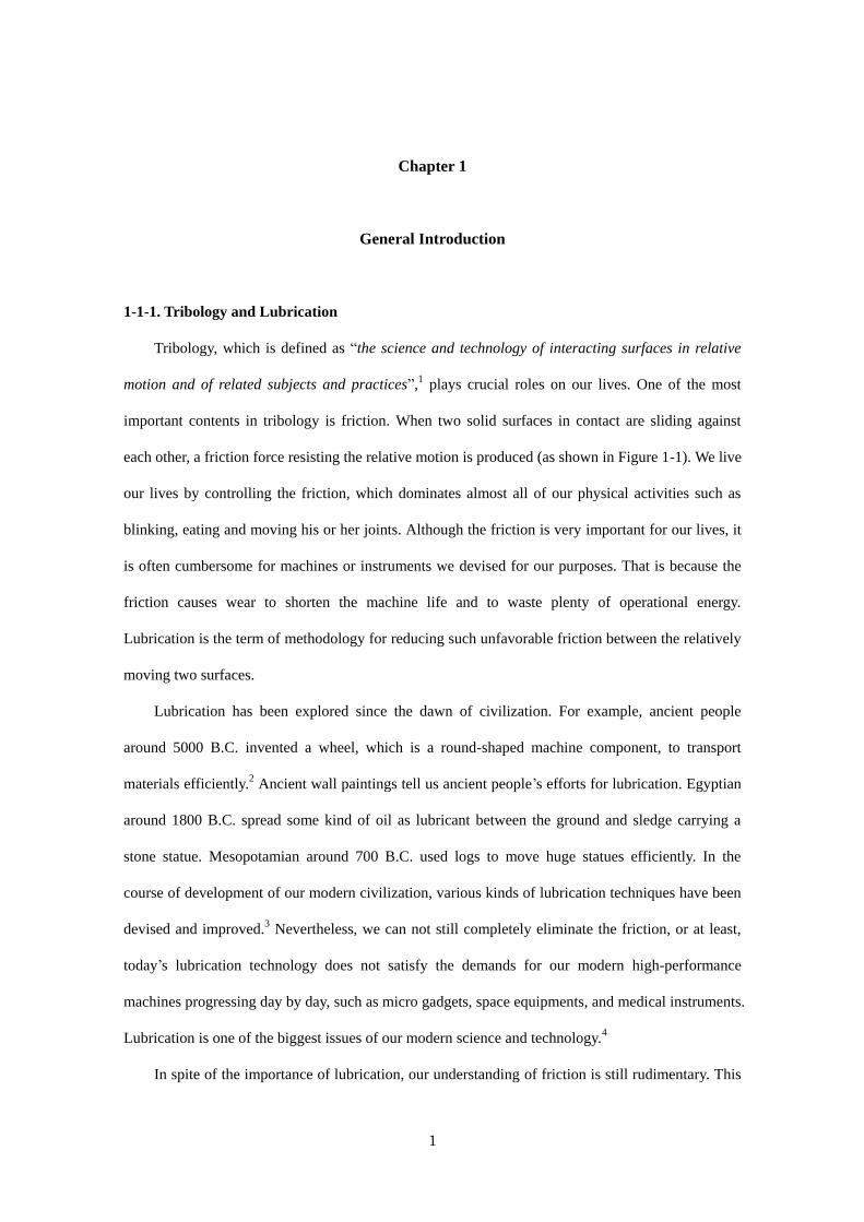
Tribology, which is defined as “the science and technology of interacting surfaces in relative
motion and of related subjects and practices”,1 plays crucial roles on our lives. One of the most
important contents in tribology is friction. When two solid surfaces in contact are sliding against
each other, a friction force resisting the relative motion is produced (as shown in Figure 1-1). We live
our lives by controlling the friction, which dominates almost all of our physical activities such as
blinking, eating and moving his or her joints. Although the friction is very important for our lives, it
is often cumbersome for machines or instruments we devised for our purposes. That is because the
friction causes wear to shorten the machine life and to waste plenty of operational energy.
Lubrication is the term of methodology for reducing such unfavorable friction between the relatively
moving two surfaces.
Lubrication has been explored since the dawn of civilization. For example, ancient people
around 5000 B.C. invented a wheel, which is a round-shaped machine component, to transport
materials efficiently.2 Ancient wall paintings tell us ancient people’s efforts for lubrication. Egyptian
around 1800 B.C. spread some kind of oil as lubricant between the ground and sledge carrying a
stone statue. Mesopotamian around 700 B.C. used logs to move huge statues efficiently. In the
course of development of our modern civilization, various kinds of lubrication techniques have been
devised and improved.3 Nevertheless, we can not still completely eliminate the friction, or at least,
today’s lubrication technology does not satisfy the demands for our modern high-performance
machines progressing day by day, such as micro gadgets, space equipments, and medical instruments.
Lubrication is one of the biggest issues of our modern science and technology.4
In spite of the importance of lubrication, our understanding of friction is still rudimentary. This
Chapter 1
2
results from the complexity of tribology; namely, a wide range of factors including not only the
chemical and physical properties of contact surfaces, surface asperity (convexity and concavity),
surface aging (wear), rheological character of lubricant are dynamically involved and mutually
related. The experimental technique to directly observe the interface between two lubricating
surfaces under the condition controlling such factors is now limited, which also hinders the
development of tribology.5
1-1-2. Lubrication Mechanism
Recent development of new experimental technique, such as quartz crystal microbalance
(QCM),6 surface force apparatus (SFA)
7 and atomic force microscope (AFM),
8 has enabled us to
study the friction at the molecular scale. Many of experimental results obtained through these new
techniques, however, can not describe the equation of friction. We still have to rely on empirical
knowledge and extensive experience for the prediction of friction.
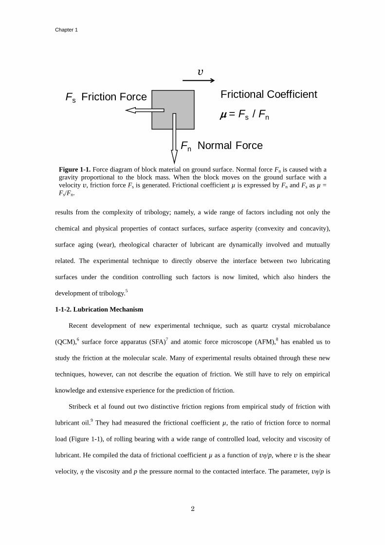
Stribeck et al found out two distinctive friction regions from empirical study of friction with
lubricant oil.9 They had measured the frictional coefficient µ, the ratio of friction force to normal
load (Figure 1-1), of rolling bearing with a wide range of controlled load, velocity and viscosity of
lubricant. He compiled the data of frictional coefficient µ as a function of vη/p, where v is the shear
velocity, η the viscosity and p the pressure normal to the contacted interface. The parameter, vη/p is
Figure 1-1. Force diagram of block material on ground surface. Normal force Fn is caused with a
gravity proportional to the block mass. When the block moves on the ground surface with a
velocity v, friction force Fs is generated. Frictional coefficient µ is expressed by Fn and Fs as µ =
Fs/Fn.
Fn Normal Force
Fs Friction Force
v
Frictional Coefficient
m = Fs / Fn
General Introduction
3
called the bearing characteristic number. This is shown in the so-called Stribeck diagram (Figure
1-2). According to the results, he divided the friction state into two distinctive regimes in a view of
what determines the friction force. These regimes are called (I) Hydrodynamic lubrication and (II)
Boundary lubrication, as will be summarized below.
(I) Hydrodynamic lubrication is the lubrication in which a fluid lubricant is filled between
relatively moving two surfaces. The fluid lubricant hydrodynamically prevents direct contact of
two surfaces, decreasing the friction (typically to be 0.001~0.01 in µ), minimizing the frictional
wear, and then attaining an ideal frictional state. The friction force in hydrodynamic lubrication
is determined by rheological character of the fluid lubricant. If the fluid lubricant is a
Newtonian fluid, the friction force can be formulated from the equation of viscosity resistance
as,
Figure 1-2. Stribeck diagram for lubricated friction surfaces. Frictional coefficient µ is depicted
against vη/p. There are two distinct friction regimes; boundary lubrication with a relatively high
frictional coefficient, and hydrodynamic lubrication with a low frictional coefficient with apparent
dependence on bearing characteristic number. In the diagram, the strategy for better lubrication is
indicated by a grey arrow; decreasing µ in boundary lubrication and expanding hydrodynamic
lubrication region.
Hydrodynamic
Lubrication
Bearing Characteristic Number, vh/p
Fri
ction
al C
oeff
icie
nt、
m Boundary
Lubrication
Chapter 1
4
µ = vη/dp (1-1)
where d denotes the thickness of a fluid lubricant layer.
(II) The fluid lubricant is squeezed out between two lubricating surfaces with increasing
normal load or decreasing velocity, and finally their direct contact occurs. This state is the
boundary lubrication. Some overcoats of lubricating surfaces prevent adhesion of two solids,
serving as a lubricant. Under ambient frictional condition, an oxide film or an adsorbed
molecular layer (water or an organic molecule from air) can also be a lubricant.10
Such
overcoats are effective as lubricants even if they are monomolecular layer.11
It is considered that van der Waals force is the origin of friction under boundary
lubrication. When the surfaces are in contact, molecules constructing two surfaces attractively
interact each other with van der Waals force when the surfaces are in contact, producing
adhesion force and hence friction force to break free from the adhesion. The
Amontons-Coulomb law, an empirical rule about dry friction between solid materials,
applicable to boundary lubrication, suggests that (i) the friction force is proportional to the
applied load, (ii) the friction force is independent of the sliding velocity, and (iii) the friction
force is independent of the apparent area of contact.12
The frictional coefficient is difficult to be
formulated due to the complexity in this friction state, but it is empirically known that the
coefficient is typically 100 times higher than that under hydrodynamic lubrication.
Except for these lubrication mechanisms, there are several kinds of lubrication states such as
elastohydrodynamic lubrication and mixed lubrication, which are now basically understood with
combination of those two lubrication mechanisms.
1-1-3. Lubrication Technique
We can set guidance for lubrication techniques from the lubrication mechanisms as mentioned
above. Briefly speaking, the key for lubrication is how we can afford or keep a hydrodynamic
lubrication state by effectively holding a lubricant fluid between surfaces. At the same time, the
General Introduction
5
friction in boundary lubrication state should be also suppressed.
To reduce the friction in boundary lubrication, adhesion between the relatively moving two
surfaces should be alleviated. While the molecule inside materials in a bulk state is stabilized by
adjacent molecules with van der Waals force or covalent bonding, the molecule at the outermost
surface is usually unstable, in other words, chemically activated because of the incomplete
surrounding by neighbor molecules. The outermost-surface molecule more or less tries to seize other
molecules out of the materials, leading to strong adhesion.10
Effective lubrication can not be desired
in this state. The surfaces should be covered with a chemically stable layer to prevent such adhesion.
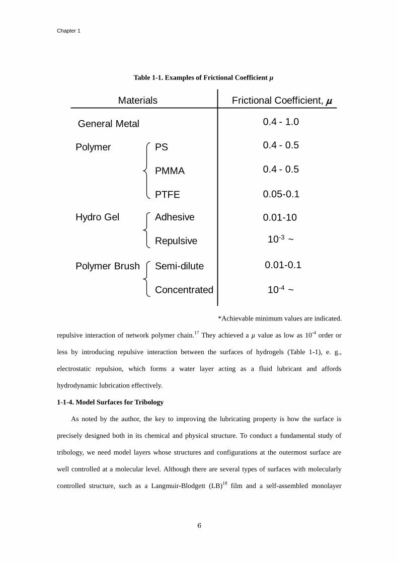
In ambient friction of common solid substances, an oxide film or a molecule-absorbed layer
functions as a protection layer against adhesion, giving µ of 0.4 - 1.0 on general metals as shown in
Table 1-1. Polytetrafluoroethylene (PTFE, known as Teflon, a trade name of PTFE) is used as a
material with high performance in lubrication. PTFE is much chemically stable and hardly react with
anything. This feature of PTFE leads to less adhesive each other, which eventually develops a low µ
value. Actually, PTFE shows particularly less µ (0.05 - 0.1) than that of other solid material, and is
used as a self-lubricant material.13
Molybdenum disulfide and graphite are also used as lubricants in
particulate dispersion state in grease.14
It is known that their molecular structures have lamellar
morphology with very weak interaction between adjacent layers and that their layers are easy to be
delaminated, which affords a low µ value.15
On the other hand, lubricant fluid should also be hold on for hydrodynamic lubrication. Viscous
oil has been used for traditional lubricant fluid. Higher viscosity is required to maintain a fluid film
between lubricating two surfaces but raises the µ as described in Equation (1-1). A precisely
patterned and indented surface enables lubricant fluid to be kept, easily affording hydrodynamic
lubrication at lower velocity, as is adopted as micro-groove bearing.16
Gel is one of the most
interesting materials as lubricant since it can contain much solvent in its polymer-network structure.
Various kinds of hydro-gels are in our bodies, enabling us to blink, eat something, and move our
joints very smoothly. Osada et al revealed that the friction of hydro-gels is dominated by adhesive or
Chapter 1
6
repulsive interaction of network polymer chain.17
They achieved a µ value as low as 10-4
order or
less by introducing repulsive interaction between the surfaces of hydrogels (Table 1-1), e. g.,
electrostatic repulsion, which forms a water layer acting as a fluid lubricant and affords
hydrodynamic lubrication effectively.
1-1-4. Model Surfaces for Tribology
As noted by the author, the key to improving the lubricating property is how the surface is
precisely designed both in its chemical and physical structure. To conduct a fundamental study of
tribology, we need model layers whose structures and configurations at the outermost surface are
well controlled at a molecular level. Although there are several types of surfaces with molecularly
controlled structure, such as a Langmuir-Blodgett (LB)18
film and a self-assembled monolayer
Table 1-1. Examples of Frictional Coefficient µ
*Achievable minimum values are indicated.
Materials Frictional Coefficient, m
General Metal
Polymer PS
PMMA
PTFE
Hydro Gel Adhesive
Repulsive
Polymer Brush Semi-dilute
Concentrated
0.4 - 1.0
0.4 - 0.5
0.4 - 0.5
0.05-0.1
0.01-10
10-3 ~
10-4 ~
0.01-0.1
General Introduction
7
(SAM),19
an architecture consisting of polymer chains tethered to a solid surface at one end (polymer
brush) has attracted increasing attention, because it plays an important role in many areas of science
and technology, e.g., colloid stabilization, adhesion, rheology, and tribology.20
Strategies have been
developed to introduce polymer chains onto surfaces using chemical (through covalent bonding) and
physical (by physisorption) methodologies.21
Physisorption involves the absorption of a block
copolymer with a segment which sticks to the substrate surface. Such polymer chains are not stably
attached, particularly under conditions in which high shear forces are involved. In order to achieve
stable interfacial compatibility, covalent bonding is preferred. Techniques for graft polymer chains
can be categorized into two methods. The first method is called as the “grafting-to” method, which
involves preformed polymers with reactive sites.22
The second method is called as “grafting-from”
method which conducts the direct growth of polymer chains from the surface, the details of which
will be described below.
1-1-5. Friction of Polymer Brush
The controlled fabrication of model surfaces as well as recent improvement in SFA and AFM as
nano-tribometers have enabled us to study the origins of friction forces. Klein et al studied the
friction of a solvent swollen polymer brushes prepared by the “grafting-to” method and found that
the polymer brush considerably decreased the friction force in a wide range of normal loads and
sliding velocities as compared to the case of the absence of polymer chains.23
This decrease
corresponded to a reduction in the frictional coefficient by two to three orders of magnitude. This
study also revealed that the so-called stick-slip behavior characterizing the trace in the case without
brushes was less marked and was seen to come into effect only at very high compressions on
polymer-attached surfaces. The lubrication effect of the brush layer is attributed first to the adhesion
of relatively moving surfaces being prevented via steric repulsion of the swollen brush layers. Klein
et al. also presented a theoretical derivation on the friction of brushes and explained that the limited
interpenetration of brush layers facilitated the effective lubrication.24
Their theoretical expression
predicts that the smaller the screening length is at the anchoring surface (i.e. the denser brush), the
Chapter 1
8
greater the effective lubrication is. However, the graft densities of their brushes considered were
limited to small values that corresponded to that of a dilute polymer solution, because the
polymer-tethered surfaces were assumed to have been fabricated by the grafting-to method.
1-1-6. Surface-Initiated Polymerization
The grafting-from method, referred to as surface-initiated polymerization and first investigated
by Prucker and Rühe,25
makes it possible to achieve denser grafting of polymers than the
“grafting-to” one. This method is divided into two processes. First, an initiator is introduced onto a
solid surface using, e.g., a bifunctional compound that is capable of covalently bonding with a
surface and initiating polymerization. Second, polymerization is carried out from initiating sites on
the surface. In this technique, the addition of a monomer to the end of a growing chain is less
hindered by chains that have been grafted. Therefore, the grafting-from method is more suitable than
the grafting-to one to produce polymer-grafted surfaces with greater thicknesses and higher graft
densities.
Surface-initiated polymerization has been carried out using a variety of polymerization
techniques, including free radical,25
ionic,26
and ring-opening methathesis27
polymerizations. In
particular, the application of living polymerizations offers clear advantages in that it provides not
only a fine control of chain length, its distribution, monomer sequence and topology of graft
polymers (e.g., random/block/gradient copolymers, comb-like or branched polymers, and
crosslinked polymers) but also a dramatic increase in graft density. The reason for this increase is
that all the graft chains grow more or less simultaneously, with their active chain ends concentrated
near the outermost surface of the graft layer. Among living polymerization techniques, living radical
polymerization (LRP) is one of the most promising routes for densely grafting functional polymers
owing to its tolerance to impurities and versatility in relation to various monomers. A variety of
LRPs, including nitroxide-mediated polymerization (NMP),28
atom transfer radical polymerization
(ATRP),29
and reversible addition-fragmentation chain transfer (RAFT)30
polymerization, have
already been applied to surface-initiated polymerization by immobilizing either a dormant species or
General Introduction
9
a conventional radical initiator on the surface. In the latter case, a capping agent is added in a
solution phase (reverse LRP). Recently, organotellurium-mediated radical polymerization (TERP)31
and reversible chain transfer catalyzed polymerization (RTCP)32
have also been gaining attention as
new classes of LRP with good controllability.
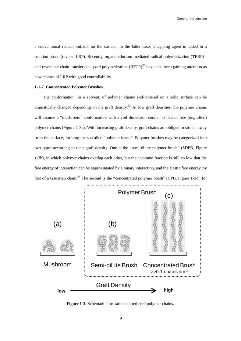
1-1-7. Concentrated Polymer Brushes
The conformation, in a solvent, of polymer chains end-tethered on a solid surface can be
dramatically changed depending on the graft density.33
At low graft densities, the polymer chains
will assume a “mushroom” conformation with a coil dimension similar to that of free (ungrafted)
polymer chains (Figure 1-3a). With increasing graft density, graft chains are obliged to stretch away
from the surface, forming the so-called “polymer brush”. Polymer brushes may be categorized into
two types according to their graft density. One is the “semi-dilute polymer brush” (SDPB, Figure
1-3b), in which polymer chains overlap each other, but their volume fraction is still so low that the
free energy of interaction can be approximated by a binary interaction, and the elastic free energy, by
that of a Gaussian chain.34
The second is the “concentrated polymer brush” (CPB, Figure 1-3c), for
Figure 1-3. Schematic illustrations of tethered polymer chains.
Concentrated Brush>>0.1 chains nm-2
Semi-dilute BrushMushroom
Graft Densitylow high
Polymer Brush
(a) (b)
(c)
Chapter 1
10
which the above-mentioned approximations are no longer valid and higher-order interactions must
be taken into account. Theoretical analyses taking these interactions into account have predicted that
the repulsive force will increase much more steeply with increasing graft density.35
Fukuda et al. firstly conducted systematic studies on CPBs using samples of low-polydispersity
poly (methyl methacrylate) (PMMA) that was densely grafted onto a surface by surface-initiated
ATRP. Recent studies have revealed that the CPBs indeed have both the structure and properties
significantly different from those of SDPBs. In particular, the CPB of PMMA formed on a silicon
wafer is highly swollen in a good solvent, such that it gives an equilibrium swollen thickness as large
as 80 - 90% of the full contour length of the graft chains, suggesting that these chains are extended to
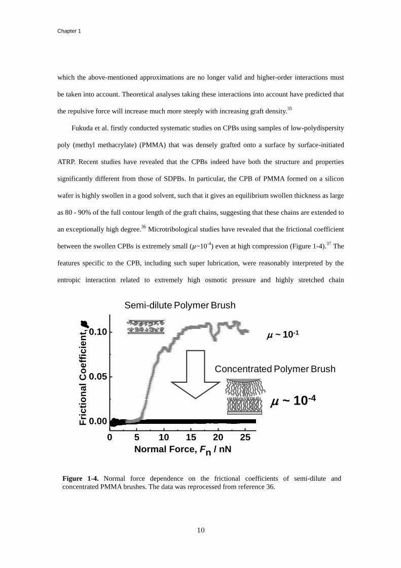
an exceptionally high degree.36
Microtribological studies have revealed that the frictional coefficient
between the swollen CPBs is extremely small (µ~10-4
) even at high compression (Figure 1-4).37
The
features specific to the CPB, including such super lubrication, were reasonably interpreted by the
entropic interaction related to extremely high osmotic pressure and highly stretched chain
Figure 1-4. Normal force dependence on the frictional coefficients of semi-dilute and
concentrated PMMA brushes. The data was reprocessed from reference 36.
0 5 10 15 20 25
0.00
0.05
0.10
Fri
cti
on
al
Co
eff
icie
nt,
m
Normal Force, Fn / nN
m ~ 10-4
m ~ 10-1
Semi-dilute Polymer Brush
Concentrated Polymer Brush
General Introduction
11
conformation and termed as the “concentrated-brush effect”.
1-2. Background and Purpose of This Thesis
Although the CPB is already known to afford an extremely small frictional coefficient, a
number of problems remain unsolved in order to put this excellent function into a practical
lubrication system. One of these problems stems from our lack of a detailed understanding of the
lubrication mechanism of the CPB. Fundamental and mechanistic study of the subject has hardly
been carried out because of the difficulty not only in preparing such well-defined brush samples but
also in precisely measuring their frictional property as a function of the viscosity and quality of
solvent as well as the brush-structure characteristics such as chain length, brush thickness, and
degree of swelling. Another challenge is the precise design of the CPBs for practical use, which
requires, among other factors, better control of the tribology (stimuli responsibility) and tolerance to
wearing and in some cases those as an aqueous system.
In light of the present situation, the author determined that the first objective of this thesis
would be to verify the lubrication mechanism of the CPB with precise control of the brush structure.
The ultra-low frictional property of the CPB is discussed in terms of whether or not the confronted
graft chains interpenetrate each other. Such interpenetration occurs at a certain level of compression
between SDPBs, affording a frictional transition from low to high frictional stages (µ ~ 0.01 - 0.1),
but it is dramatically suppressed between the CPBs because of entropic origins. According to the
lubrication mechanisms discussed in Section 1-1-2, the above-mentioned frictional state is
categorized as boundary lubrication, since the outermost-surface property determines the friction. On
the contrary, the regime of hydrodynamic lubrication for a solvent-swollen CPB remains little
understood. The author achieves his first objective by analyzing the friction/lubrication data as a
function of normal force, shear velocity, solvent quality (hence, degree of swelling), and solvent
viscosity. The frictional property between immiscible CPBs is also evaluated in order to confirm the
hydrodynamic and boundary lubrication proposed for the CPB.
Chapter 1
12
The achievement of the first objective enables us to then develop new designs for lubricating
materials equipped with the concentrated-brush effect. Such an ultra-low frictional property has
previously been demonstrated only for nonpolar polymer brushes of limited thicknesses owing to the
easy preparation of such brush samples. Thus, the author set up a second objective, which was to
establish newly designed CPBs of functional polymers for practical use. Water-swellable and
thermo-responsible CPBs are synthesized and investigated in terms of their frictional property in
water media, with the aim of eventual applications in biomedical materials. Another application of
this design is a polymer gel of bottle-brush type, in which the network structure of the polymer
chains can contain much solvent inside and the precise structural control of the bottle-brush polymer,
i.e., the control of the side-chain length and graft density, can be expected to introduce the
concentrated-brush effect. The author uses the most appropriate LRP technique as a versatile and
robust tool for the preparation of well-defined polymer-brush samples. In addition to this, a
methodology to precisely measure the surface interaction and swelling and friction/lubrication
properties is newly devised, particularly using a colloidal-probe technique on AFM. Such newly
designed materials may concurrently give rise to other factors, that were not previously taken into
account. The author also discusses such factors in regard to the frictional property of the CPB.
1-3. Outline of This Thesis
The purpose of this thesis is to clarify the correlation between the structure and the surface
property of a CPB and to thereby provide new guideline for the novel design of tribomaterials.
In Chapter 2, the author measures the friction force and hence the frictional coefficient µ
between CPBs of polystyrene (PS) in solvents as a function of shear velocity and degree of swelling
(Figure 1-5). The degree of swelling of a polymer-brush layer is successfully controlled by the
solvent composition of a mixture containing toluene (a good solvent for PS) and 2-propanol
(non-solvent for PS). The author analyzes the friction data collected under a wide range of
conditions, ranging from a highly stretched brush to almost shrunken states, and discusses these
General Introduction
13
mechanisms in terms of boundary lubrication and hydrodynamic lubrication.
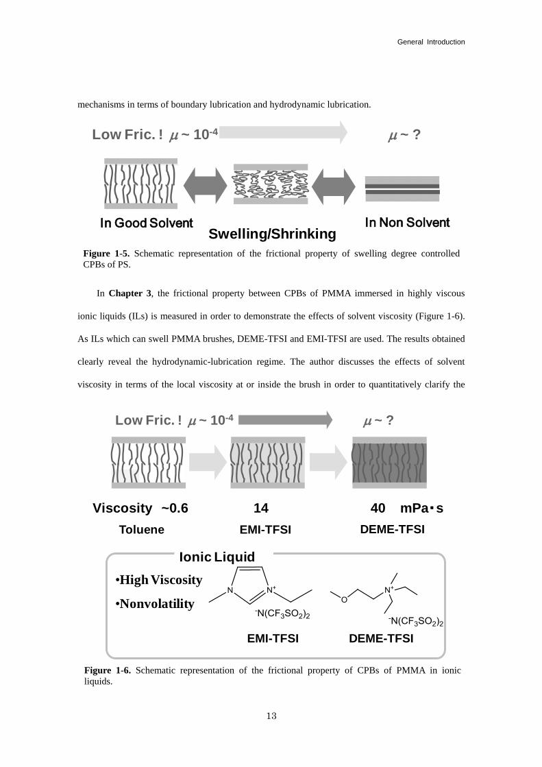
In Chapter 3, the frictional property between CPBs of PMMA immersed in highly viscous
ionic liquids (ILs) is measured in order to demonstrate the effects of solvent viscosity (Figure 1-6).
As ILs which can swell PMMA brushes, DEME-TFSI and EMI-TFSI are used. The results obtained
clearly reveal the hydrodynamic-lubrication regime. The author discusses the effects of solvent
viscosity in terms of the local viscosity at or inside the brush in order to quantitatively clarify the
Figure 1-5. Schematic representation of the frictional property of swelling degree controlled
CPBs of PS.
Swelling/Shrinking
Low Fric. ! m ~ 10-4
In Good Solvent In Non Solvent
m ~ ?
Figure 1-6. Schematic representation of the frictional property of CPBs of PMMA in ionic
liquids.
Low Fric. ! m ~ 10-4
EMI-TFSI DEME-TFSI
•High Viscosity
•Nonvolatility
Ionic Liquid
m ~ ?
DEME-TFSIEMI-TFSIToluene
Viscosity ~0.6 14 40 mPa・s
Chapter 1
14
hydrodynamic lubrication of the CPB.
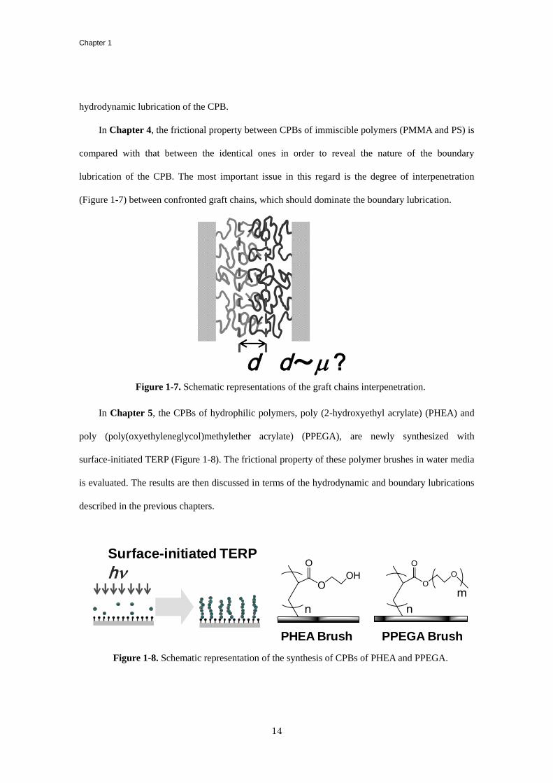
In Chapter 4, the frictional property between CPBs of immiscible polymers (PMMA and PS) is
compared with that between the identical ones in order to reveal the nature of the boundary
lubrication of the CPB. The most important issue in this regard is the degree of interpenetration
(Figure 1-7) between confronted graft chains, which should dominate the boundary lubrication.
In Chapter 5, the CPBs of hydrophilic polymers, poly (2-hydroxyethyl acrylate) (PHEA) and
poly (poly(oxyethyleneglycol)methylether acrylate) (PPEGA), are newly synthesized with
surface-initiated TERP (Figure 1-8). The frictional property of these polymer brushes in water media
is evaluated. The results are then discussed in terms of the hydrodynamic and boundary lubrications
described in the previous chapters.
Figure 1-7. Schematic representations of the graft chains interpenetration.
d~m ? d
Figure 1-8. Schematic representation of the synthesis of CPBs of PHEA and PPEGA.
PHEA Brush
Surface-initiated TERP
hn
PPEGA Brush
General Introduction
15
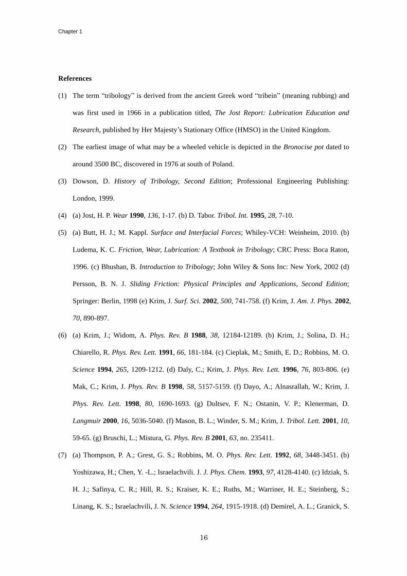
Figure 1-10. Schematic representation of the synthesis of bottle brush polymer gel.
Multi-initiatorBottlebrush
ATRP
monomer
Radical Coupling
Graft-type of Gel
Cross-link at
graft chain ends
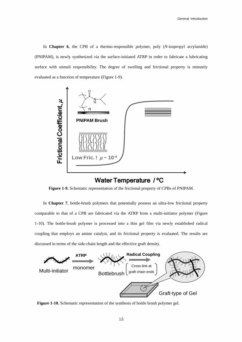
In Chapter 6, the CPB of a thermo-responsible polymer, poly (N-isopropyl acrylamide)
(PNIPAM), is newly synthesized via the surface-initiated ATRP in order to fabricate a lubricating
surface with stimuli responsibility. The degree of swelling and frictional property is minutely
evaluated as a function of temperature (Figure 1-9).
In Chapter 7, bottle-brush polymers that potentially possess an ultra-low frictional property
comparable to that of a CPB are fabricated via the ATRP from a multi-initiator polymer (Figure
1-10). The bottle-brush polymer is processed into a thin gel film via newly established radical
coupling that employs an amine catalyst, and its frictional property is evaluated. The results are
discussed in terms of the side-chain length and the effective graft density.
Figure 1-9. Schematic representation of the frictional property of CPBs of PNIPAM.
Water Temperature / ºC
Fri
ctio
na
l Co
eff
icie
nt,
m
PNIPAM Brush
Low Fric. ! m ~ 10-4
Chapter 1
16
References
(1) The term “tribology” is derived from the ancient Greek word “tribein” (meaning rubbing) and
was first used in 1966 in a publication titled, The Jost Report: Lubrication Education and
Research, published by Her Majesty’s Stationary Office (HMSO) in the United Kingdom.
(2) The earliest image of what may be a wheeled vehicle is depicted in the Bronocise pot dated to
around 3500 BC, discovered in 1976 at south of Poland.
(3) Dowson, D. History of Tribology, Second Edition; Professional Engineering Publishing:
London, 1999.
(4) (a) Jost, H. P. Wear 1990, 136, 1-17. (b) D. Tabor. Tribol. Int. 1995, 28, 7-10.
(5) (a) Butt, H. J.; M. Kappl. Surface and Interfacial Forces; Whiley-VCH: Weinheim, 2010. (b)
Ludema, K. C. Friction, Wear, Lubrication: A Textbook in Tribology; CRC Press: Boca Raton,
1996. (c) Bhushan, B. Introduction to Tribology; John Wiley & Sons Inc: New York, 2002 (d)
Persson, B. N. J. Sliding Friction: Physical Principles and Applications, Second Edition;
Springer: Berlin, 1998 (e) Krim, J. Surf. Sci. 2002, 500, 741-758. (f) Krim, J. Am. J. Phys. 2002,
70, 890-897.
(6) (a) Krim, J.; Widom, A. Phys. Rev. B 1988, 38, 12184-12189. (b) Krim, J.; Solina, D. H.;
Chiarello, R. Phys. Rev. Lett. 1991, 66, 181-184. (c) Cieplak, M.; Smith, E. D.; Robbins, M. O.
Science 1994, 265, 1209-1212. (d) Daly, C.; Krim, J. Phys. Rev. Lett. 1996, 76, 803-806. (e)
Mak, C.; Krim, J. Phys. Rev. B 1998, 58, 5157-5159. (f) Dayo, A.; Alnasrallah, W.; Krim, J.
Phys. Rev. Lett. 1998, 80, 1690-1693. (g) Dultsev, F. N.; Ostanin, V. P.; Klenerman, D.
Langmuir 2000, 16, 5036-5040. (f) Mason, B. L.; Winder, S. M.; Krim, J. Tribol. Lett. 2001, 10,
59-65. (g) Bruschi, L.; Mistura, G. Phys. Rev. B 2001, 63, no. 235411.
(7) (a) Thompson, P. A.; Grest, G. S.; Robbins, M. O. Phys. Rev. Lett. 1992, 68, 3448-3451. (b)
Yoshizawa, H.; Chen, Y. -L.; Israelachvili. J. J. Phys. Chem. 1993, 97, 4128-4140. (c) Idziak, S.
H. J.; Safinya, C. R.; Hill, R. S.; Kraiser, K. E.; Ruths, M.; Warriner, H. E.; Steinberg, S.;
Linang, K. S.; Israelachvili, J. N. Science 1994, 264, 1915-1918. (d) Demirel, A. L.; Granick, S.
General Introduction
17
Phys. Rev. Lett. 1996, 77, 4330-4333. (e) Campbell, S. E.; Luengo, G.; Srdanov, V. I.; Wudi, F.;
Israelachvili, J. N. Nature 1996, 382, 520-522. (f) Golan, Y.; Martin-Herranz, Y. A.; Li, Y.;
Safinya, C. R.; Israelachvili, J. Phys. Rev. Lett. 2001, 86, 1263-1266. (g) Raviv, U.; Giasson, S.;
Kampf, N.; Gohy, J. F.; Jerome, R.; Klein, J. Nature 2003, 425, 163-165. (h) Yamada, S. J.
Chem. Phys. 2009, 131, 184708.
(8) (a) Mate, C. M.; Mcclelland, G. M.; Erlandsson, R.; Chang, S. Phys. Rev. Lett. 1987, 59,
1942-1945. (b) Mayer, E.; Overney, R. M.; Howald, L.; Luthi, R.; Frommer, J.; Gunngherodt, J.
Phys. Rev. Lett. 1992, 69, 1777-1780. (c) Germann, G. J.; Cohen, S. R.; Neubauer, G.;
Mcclelland, G. M.; Seki, H.; Coulman, D. J. Appl. Phys. 1993, 73, 163-167. (d) Binggeli, M.;
Mate, C. M. Appl. Phys. Lett. 1994, 65, 415-417. (e) Xiao, X.; Hu, J.; Charych, D. H.; Salmeron,
M. Langmuir 1996, 12, 235-237. (f) Hirano, M.; Shinjo, K.; Kanko, R.; Murata, Y. Phys. Rev.
Lett. 1997, 78, 1448-1451. (g) Enachescu, M.; Van den Oetelaar, R. J. A.; Carpick, R. W. Tribol.
Lett. 1999, 7, 73-78. (h) Tutein, A. B.; Stuart, S. J; Harrison, J. A. Langmuir 2000, 113,
8249-8252. (i) Jung, Y. C.; Bhushan, B. Nanotechnology 2006, 17, 4970-4980. (j) Szlufarska,
I.; Chandross, M.; Carpick, R. W. J. Phys. D 2008, 41, 123001.
(9) (a) Stribeck, R. Zeitschrift des Vereines deutscher Ingenieure 1901, 45, 73-79 (Part I). & 1901,
45, 118-125 (Part II). (b) Stribeck, R. Zeitschrift des Vereines deutscher Ingenieure. 1902, 46,
1341-1348 (Part I). & 1902, 46, 1432-1438 (Part II). & 1902, 46, 1463-1470 (Part III). (d) for
recent comment, see, Jacobson, B. Tribol. Int. 2003, 36, 781-789.
(10) (a) Buckley, D. H. Surface effects in Adhesion, Friction, Wear, and Lubrication; Elsevier:
Amsterdam, 1981. (b) Feng, Z.; Tzeng, Y.; Field, J. E. J. Phys. 1992, 25, 1418-1424.
(11) Bhushan, B.; Israelachvili, J. N.; Landman, U. Nature 1995, 374, 607-616.
(12) Amonton, G. Mem. del’ Academie Royale A 1699, 275-282.
(13) (a) Fusaro, R. L. Tribol. Int. 1990, 23, 105-122. (b) Lu, Z. P.; Friedrich, K. Wear 1995, 181,
624-631. (c) Yamada, S.; Israelachvili. J. J. Phys. Chem. B 1998, 102, 234-244. (d) Theiler, G.;
Hubner, W.; Gradt, T.; Klein, P.; Friedrich, K. Tribol. Int. 2002, 35, 449-458.
Chapter 1
18
(14) (a) Kustas, F. M.; Misra, M. S.; Shepard, D. F.; Froechtenigt, J. F. Surf. Coat. Tech. 1991, 48,
113-119. (b) How, K. P.; Kalousek, J.; Magel, E. Wear 1997, 211, 134-140. (c) Chhowalla, M.;
Amaratunga, G. A. J. Nature 2000, 407, 164-167. (d) Zhang, X. -T.; Liao, G. -X.; Jin, Q. -F.;
Feng, X. -B.; Jian, X. -G. Tribol. Int. 2008, 41, 195-201.
(15) Bowden, F. P.; Tabor, D. The Friction and Lubrication of Solid; Oxford University Press: New
York, 1986.
(16) (a) Etsion, I.; Burstein, L. Tribol. Trans. 1996, 39, 677-683. (b) Wang, X.; Kato, K.; Adachi, K.;
Aizawa, K. Tribol. Int. 2003, 36, 189-197. (c) Wakuda, M.; Yamauchi, Y.; Kanzaki, S.; Yasuda,
Y. Wear 2003, 254, 356-363. (d) Costa, H. L.; Hutchings, I. M. Tribol. Int. 2007, 40,
1227-1238.
(17) (a) Gong, J.; Higa, M.; Iwasaki, Y.; Katsuyama, Y.; Osada, Y. J. Phys. Chem. B 1997, 28,
5487-5489. (b) Gong, J.; Osada, Y. J. Chem. Phys. 1998, 109, 8062-8068. (c) Gong, J.; Kagata,
G.; Osada, Y. J. Phys. Chem. B 1999, 103, 6007-6014. (d) Gong, J.; Kurokawa, T.; Narita, T.;
Kagata, G.; Osada, Y.; Nishimura, G.; Kinjo, M. J. Am. Chem. Soc. 2001, 123, 5582-5583.
(18) Zasadzinski, J. A.; Viswanathan, R.; Madsen, L.; Garnaes, J.; Schwarts, D. K. Science 1994,
263, 1726-1733.
(19) Schreiber, F. Prog. Surf. Sci. 2000, 65, 151-256.
(20) (a) Napper, D. H., Eds.; Polymeric Stabilization of Colloidal Dispersions; Academic Press:
London, 1983. (b) Raphael, E.; de Gennes, P. G. J. Phys. Chem. 1992, 96, 4002-4007. (c) Klein,
J. Annu. Rev. Mater. Sci. 1996, 26, 581-612. (d) Klein, J.; Kumacheva, E. Science 1995 269,
816-819. (e) Parnas, R. S.; Cohen, Y. Rheol. Acta 1994, 33, 485-505.
(21) Advincula, R. C.; Britain, W. J.; Caster, K. C.; Rühe, J., Eds.; Polymer Brushes; Whiley-VCH:
Weinheim, 2004.
(22) (a)Tsubokawa, N.; Hosoya, M.; Yanadori, K.; Sone, Y. J. Macromol. Sci. - Chem. 1990, A27,
445-457. (b) Bridger, K.; Vincent, B. Eur. Polym. J. 1980, 16, 1017-1021. (c) Kishida, M.;
Mishima, K.; Corretge, E.; Konishi, H.; Ikeda, Y. Biomaterials 1992, 13, 113-118. (d) Tezuka,
General Introduction
19
Y.; Nobe, S.; Shiomi, T. Macromolecules 1995, 28, 8251-8258. (e) Pitsikaris, M.; Woodward,
J.; Mays, J. W.; Hadjichristidis, N. Macromolecules 1997, 30, 5384-5389. (f) Mousanda, B.
Polymer 1997, 38, 5301-5306.
(23) (a) Klein, J.; Kumacheva, E.; Mahalu, D.; Pherahia, D. Macromol. Symp. 1995, 98, 1149-1158.
(b) Klein, J.; Kumacheva, E.; Mahalu, D.; Perahia, D.; Fetters, L. J. Nature 1994, 370, 634-636.
(c) Klein, J.; Kumacheva, E.; Perahia, D.; Mahalu, D.; Warburg, S. Faraday Disc. 1994, 98,
173-188. (d) Luckham, P. F.; Manimaaran, S. Adv. Colloid Interface Sci. 1997, 73, 1-46.
(24) Klein, J. Ann. Rev. Mat. Sci. 1996, 26, 581-612.
(25) (a) Prucker, O.; Rühe, J. Macromolecules 1998, 31, 592-601. (b) Prucker, O.; Rühe, J.
Macromolecules 1998, 31, 602-613.
(26) (a) Zhao, B.; Brittain, W. J. Macromolecules 1998, 31, 592-601. (b) Jordan, R.; Ulman, A.;
Rafailovick, M. H.; Sokolov, J. J. Am. Chem. Soc. 1999, 121, 1016-1022. (c) Advincula, R.;
Zhou, Q. G.; Park, M.; Wang, S. G.; Mays, J.; Sakellariou, G.; Pispas, S.; Hadjichristidis, N.
Langmuir 2002, 18, 8672-8684
(27) (a) Kim, N. Y.; Jeon, N. L.; Choi, I. S.; Takami, S.; Harada, Y.; Finnie, K. R.; Girolami, G. S;
Nuzzo, R. G.; Whitesides, G. M.; Laibinis, P. E. Macromolecules 2000, 33, 2793-2795. (b)
Juang, A.; Scherman, O. A.; Grubbs, R. H.; Lewis, N. S. Langmuir 2001, 17, 1321-1323. (c)
Moon, J. H.; Swager, T. M. Macromolecules 2002, 35, 6086-6089.
(28) (a) Husseman, M.; Malmström, E. E.; McNamara, M.; Mate, M.; Mecerreyes, D.; Benoit, D.
G.; Hedrick, J. L.; Mansky, P.; Huang, E.; Russel, T. P.; Hawker, C. J. Macromolecules 1999, 32,
1424-1431. (b) Shah, R. R.; Mecerreyes, D.; Husseman, M.; Rees, I.; Abbott, N. L.; Hawker, C.
J.; Hedrick, J. L. Macromolecules. 2000 33, 597-605. (c) Devaux, C.; Chapel, J. P.; Beyou, E.;
Chaumont, P. Eur. Phys. J. E 2002, 7, 345-352.
(29) (a) Ejaz, M.; Yamamoto, S.; Ohno, K.; Tsujii, Y.; Fukuda, T. Macromolecules 1998, 31,
5934-5936. (b) Huang, W. X.; Wirth, M. J. Macromolecules 1999, 32, 1694-1696. (c)
Matyjaszewski, K.; Miller, P. J.; Shukla, N.; Immaraporn, B.; Gelman, A.; Luokala, B.B.;
Chapter 1
20
Siclovan, T. M.; Kickelbick, G.; Vallant, T.; Hoffmann, H.; Pakula, T. Macromolecules 1999, 32,
8716-8724. (d) Xiao, D. Q.; Wirth, M. J. Macromolecules 2002, 35, 2919-2925. (f) Jeyaprakash,
J. D.; Samuel, S.; Dhamodharan, R.; Rühe, J. Macromol. Rap. Comm. 2002, 23, 612-616. (g)
Ramakrishnan, A.; Dhamodharan, R.; Rühe, J. Macromol. Rap. Comm. 2002, 23, 612-616. (h)
Parvole, J.; Laruelle, G.; Guimon, C.; Francois, J.; Billon, L. Macromol. Rap. Comm. 2003, 107,
10198-10205. (i) Yu, W. H.; Kang, E. T.; Neoh, K. G.; Zhu, S. P. J. Phys. Chem. B 2003, 107,
10198-10205. (j) Kim, J. -B.; Bruening, M. L.; Baker, G. L. J. Am. Chem. Soc. 2000, 122,
7616-7617. (k) Kim, J. -B.; Huang, W. X.; Miller, M. D.; Baker, G. L.; Bruening, M. L. J.
Polym. Sci. Part A: Polym. Chem. 2003, 41, 386-394. (l) Huang, W.; Kim, J. -B.; Bruening, M.
L.; Baker, G. L. Macromolecules 2002, 35, 1175-1179. (m) Jones, D. M.; Brown, A. A.; Huck,
W. T. S. Langmuir 2002, 18, 1265-1269. (n) Desai, S. M.; Solanky, S. S.; Mandale, A. B.;
Rathore, K.; Singh, R. P. Polymer 2003, 44, 7645-7649.
(30) (a) Baum, M.; Brittain, W. J. Macromolecules 2002, 35, 610-615. (b) Zhai, G.; Yu, W. H.; Kang,
E. T.; Neoh, K. G.; Huang, C. C.; Liaw, D. J. Indust. Eng. Chem. Res. 2004, 43, 1673-1680. (c)
Tsujii, Y.; Ejaz, M.; Sato, K.; Goto, A.; Fukuda, T. Macromolecules 2001, 34, 8872-8878.
(31) (a) Yamago, S.; Lida, K.; Yoshida, J. J. Am. Chem. Soc. 2002, 124, 13666-13667. (b) Yamago,
S.; Iida, K.; Nakajima, M.; Yoshida, J. Macromolecules 2003, 36, 3793-3796. (c) Yamago, S.
Chem. Rev. 2009, 109, 5051-5068. (d) Yamago, S.; Ukai, Y.; Matsumoto, A.; Nakamura, Y. J.
Am. Chem. Soc. 2009, 131, 2100-2101.
(32) (a) Goto, A.; Zushi, H.; Hirai, N.; Wakada, T.; Tsujii, Y.; Fukuda, T. J. Am. Chem. Soc. 2007,
129, 13347-13354. (b) Goto, A.; Tsujii, Y.; Fukuda, T. Polymer 2008, 49, 5177-5185. (c) Goto,
A.; Wakada, T.; Fukuda, T.; Tsujii, Y. Macromol. Chem. Phys. 2010, 211, 594-600. (d) Goto, A.;
Hirai, N.; Nagasawa, K.; Tsujii, Y.; Fukuda, T.; Kaji, H. Macromolecules 2010, 43, 7971-7978.
(33) (a) Israelachvili, J. N. Intermolecular and Surface Forces, Second Edition.; Academic Press:
London, 1992. (b) Halperin, A.; Tirrell, M.; Lodge, T. P. Adv. Polym. Sci. 1992, 100, 31-71. (c)
Kawaguchi, M.; Takahashi, A. Adv. Colloid. Interface Sci. 1992, 37, 219-317.
General Introduction
21
(34) (a) Taunton, H. J.; Toprakcioglu, C.; Fetters, L. J.; Klein, J. Macromolecules 1990, 23, 571-580.
(b) Courvoisier, A.; Isel, R.; Francois, J.; Maaloum, M. Langmuir 1998, 14, 3727-3729. (c)
Satija, S. K.; Majkrzak, C. F.; Russell, T. P.; Sinha, S. K.; Sirota, E. B.; Hughes, G. J.
Macromolecules 1990, 23, 3860-3864. (d) Levicky, R.; Koneripalli, N.; Tirrell, M.; Satija, G. J.
Macromolecules 1998, 31, 3731-3734. (e) Cosgrove, T.; Heath, T. G.; Phipps, J. S.; Richardson,
R. M. Macromolecules 1991, 24, 94-98. (f) Field, J. B.; Toprakcioglu, C.; Ball, R. C.; Stanley,
H. B.; Dai, L.; Barford, W.; Penfold, J.; Smith, G.; Hamilton, W. Macromolecules 1992, 25,
434-439. (g) Anastassopoulos, D. L.; Vradis, A. A.; Toprakcioglu, C.; Smith, G. S.; Dai, L.
Macromolecules 1998, 31, 9369-9371.
(35) (a) Shim, D. F. K.; Cates, M. E. J. Phys. (France) 1989, 50, 3535-3551. (b) Lai, P. Y.; Halperin,
A. Macromolecules 1991, 24, 4981-4982.
(36) (a) Yamamoto, S.; Ejaz, M.; Tsujii, Y.; Matsumoto, M.; Fukuda, T. Macromolecules 2000, 33,
5602-5607. (b) Yamamoto, S.; Ejaz, M.; Tsujii, Y.; Fukuda, T. Macromolecules 2000, 33,
5608-5612.
(37) (a) Tsujii, Y.; Okayasu, K.; Ohno, K.; Fukuda, T. Polym. Prep. (Am. Chem. Soc., DiV. Polym.
Chem.) 2005, 46 (2), 85-86. (b) Tsujii, Y.; Nomura, A.; Okayasu, K.; Gao, W.; Fukuda, T. J.
Phys.: Conference Series 2009, 184, 012031.

Chapter 1
22
23
Chapter 2
Lubrication Mechanism of Concentrated Polymer Brushes in Solvents: Effect of Solvent
Quality and Thereby Swelling State
2-1. Introduction
The friction/lubrication property of polymer-coated surfaces is an important characteristic in
many areas of science and technology.1 Polymer brushes, in particular, have been extensively studied
because of their efficiency at modifying the equilibria and dynamic properties of surfaces.2 In
solvents, they have been shown to be efficient lubricants by forming layers at moderate shear
velocities and loads.2f-h
Previously, well-defined polymer brushes were prepared using
end-functionalized polymers or block copolymers with the terminal group or one of the blocks
selectively adsorbed onto a surface. These systems possess rather low graft densities of typically
0.001 - 0.05 chains/nm2, corresponding to the regime of “semi-dilute polymer brush (SDPB)”, which
limits their practical application requiring a brush layer thick enough to hold a wide range of
pressure and shear velocity.
Densely grafting well-defined polymers on various kinds of materials including inorganic
substrates was achieved using the living radical polymerization technique.3 The graft density of thus
obtained polymer brushes was about an order of magnitude higher than those of typical SDPBs,
penetrating deep into the regime of “concentrated polymer brush (CPB)”, which had been little
explored systematically because of the unavailability of such brush samples. Recent studies revealed
that these CPBs have structures and properties quite different and even unpredictable from those of
SDPBs: most strikingly, the CPBs of poly (methyl methacrylate) (PMMA) swollen in a good solvent
(toluene) exhibit equilibrium film thicknesses as large as 80% - 90% of the full (contour) length of
the graft chains.4 More interestingly, the microtribological analysis using an atomic force microscope
Chapter 2
24
(AFM) revealed that in a good solvent, the CPBs of PMMA exhibit super lubrication with an
extremely low frictional coefficient (µ ~ 10-4
) for any applied load.5 Other examples of polymer
brushes with excellent lubrication properties have been reported for the SDPBs of polyelectrolyte
and for a polyzwitterionic brush (whose graft density was not reported).2f
The excellent
water-lubrication characteristics were ascribed to the osmotic pressure of counter ion and the strong
hydration of charged groups. By contrast, the super lubrication observed for the swollen CPBs of
PMMA was previously attributed to the strong resistance of CPBs against mixing with each other:
that is, confronted CPBs (of the same kind) do not mix with each other at high compression. This
new mechanism was expected to be common to CPB/good solvent systems.
Parallel to the friction studies of CPBs, Kobayashi et al. studied the tribological properties of
densely grafted polymer brushes of various polymers using a tribometer with a probe ball 5 mm in
diameter.6 They revealed lower frictional forces and improved wear resistance as compared with the
corresponding spin-cast polymer film. The frictional coefficient µ for these systems was not of the
same value reported above; the discrepancy may be attributed to the different experimental
conditions employed. Microtribological measurements are suitable for revealing the intrinsic
friction/lubrication properties of solvent-swollen polymer brushes with, for example, sub-micron
thickness.
As mentioned above, CPB successfully achieved super lubrication. The solvent-swollen
polymer brush can be regarded as a thin lubricating layer. Concerning the fluid character of the brush
layers, the thickness and viscosity of the lubricating layer and the shear velocity should affect the
frictional/lubrication property.7 However, these effects warrant further investigation. In this work,
AFM-microtribological studies were carried out on well-defined CPBs of polystyrene (PS) under
varying degrees of swelling, which was precisely controlled by changing the composition of
good/non-solvent mixtures. The lubrication mechanism of CPBs is discussed in detail in terms of
Effect of Solvent Quality and Thereby Swelling State
25
hydrodynamic and boundary lubrications.
2-2. Experimental Section
2-2-1. Materials
Styrene (99%, Nacalai Tesque, Inc., Japan) was passed through a column of basic alumina to
remove inhibitors. Cu(I)Br (99.9%, Wako Pure Chemical Ind., Ltd., Japan), ethyl
2-bromoisobutylate (EBIB, 99%, Wako), and 4,4’-dinonyl-2,2’-bipyridine (dNbipy, 97%, Aldrich)
were used as received. (2-bromo-2-methyl) propionyloxyhexyltriethoxysilane (BHE, a fixable
initiator for ATRP) was prepared as previously reported.8 All other reagents were obtained from
commercial source and used as received.
A silicon wafer (Ferrotec Corp., Japan, one side chemicaly/mechanicaly polished, 525 mm
thickness) was cleaned by ultrasonication in CHCl3 for 15 min and ultraviolet (UV) / ozone
treatment for 10 min before fixation of BHE. A silica particle (SiP, HIPRESICA SP, radius R of 5
µm) used as a probe for the AFM measurement was obtained from Ube Nitto Kasei Co., Ltd., Japan.
2-2-2. Synthesis of Concentrated PS Brushes via Surface-Initiated ATRP
Well-defined CPBs of PS were prepared by surface-initiated ATRP. To immobilize the surface
initiator, BHE, a silicon wafer was immersed in an ethanol solution containing BHE (1 wt%) and
28%-aqueous ammonium (5 wt%) for 12 h at room temperature, copiously rinsed with ethanol, and
then dried. The BHE-immobilized silicon wafer was subjected to graft polymerization at 110oC for 2
h in a styrene solution containing Cu(I)Br (87 mM), dNbipy (170 mM), and EBIB (8.7 mM) under
argon atmosphere. EBIB was added as a free initiator not only to control the polymerization by the
so-called persistent radical effect but also to yield free polymers, which are useful as a measure of
the molecular weight Mn and molecular weight distribution Mw/Mn of the graft chains.3 Good
agreement in Mn and Mw/Mn between the graft and free polymers has been reported by several
research groups.9 After polymerization, the substrate was rinsed in a Soxhlet extractor with toluene
Chapter 2
26
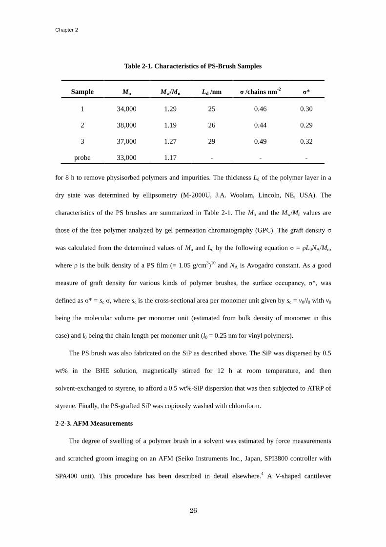
for 8 h to remove physisorbed polymers and impurities. The thickness Ld of the polymer layer in a
dry state was determined by ellipsometry (M-2000U, J.A. Woolam, Lincoln, NE, USA). The
characteristics of the PS brushes are summarized in Table 2-1. The Mn and the Mw/Mn values are
those of the free polymer analyzed by gel permeation chromatography (GPC). The graft density σ
was calculated from the determined values of Mn and Ld by the following equation σ = ρLdNA/Mn,
where ρ is the bulk density of a PS film (= 1.05 g/cm3)
10 and NA is Avogadro constant. As a good
measure of graft density for various kinds of polymer brushes, the surface occupancy, σ*, was
defined as σ* = sc σ, where sc is the cross-sectional area per monomer unit given by sc = v0/l0 with v0
being the molecular volume per monomer unit (estimated from bulk density of monomer in this
case) and l0 being the chain length per monomer unit (l0 = 0.25 nm for vinyl polymers).
The PS brush was also fabricated on the SiP as described above. The SiP was dispersed by 0.5
wt% in the BHE solution, magnetically stirred for 12 h at room temperature, and then
solvent-exchanged to styrene, to afford a 0.5 wt%-SiP dispersion that was then subjected to ATRP of
styrene. Finally, the PS-grafted SiP was copiously washed with chloroform.
2-2-3. AFM Measurements
The degree of swelling of a polymer brush in a solvent was estimated by force measurements
and scratched groom imaging on an AFM (Seiko Instruments Inc., Japan, SPI3800 controller with
SPA400 unit). This procedure has been described in detail elsewhere.4 A V-shaped cantilever
Table 2-1. Characteristics of PS-Brush Samples
Sample Mn Mw/Mn Ld /nm σ /chains nm-2
σ*
1 34,000 1.29 25 0.46 0.30
2 38,000 1.19 26 0.44 0.29
3 37,000 1.27 29 0.49 0.32
probe 33,000 1.17 - - -
Effect of Solvent Quality and Thereby Swelling State
27
OMCL-TR800 (Olympus Corp., Japan, normal spring constant kn = 0.15 N/m) was used with a bare
(unmodified) SiP probe attached using a two-component epoxy-resin adhesive. The R of the probe
particle was 5.0 mm, much larger than the size of graft layer so that the graft chains could be viewed
as being compressed by a flat surface. A liquid cell was used for the measurement in mixtures of
toluene and 2-propanol with different compositions (ƒTOL, volume fraction of toluene). The mixed
solvents were filtered through a cellulose porous membrane (Whatman, diameter 0.1 µm) before use.
The normal displacement z of the cantilever was monitored as a function of separation in
approaching/retracting modes; typically, an approaching/retracting speed of 80 nm/s, and at least 8
force curves were taken at different locations. The interaction force, i.e., the normal force, Fn, was
estimated as follows,
Fn = kn ·z = kn · (DIF · SDIF) (2-1)
where DIF (V) and SDIF (m/V) are the signal intensity and sensitivity of the vertical deflection,
respectively. The latter value was determined for each force curve in the so-called
constant-compliance region where the cantilever deflection increased linearly with decreasing
separations. The AFM raw data of cantilever deflection vs displacement were converted into Fn as a
function of separation D' according to the principle of Ducker et al.11
The separation D' is not the
distance from the substrate but that from the constant-compliance region. In a system with a dense
polymer layer, the distance between D' = 0 plane and the substrate surface, which is called as “offset
distance D0”, can be very large. The offset distance D0 was measured by AFM-imaging under a
constant force mode by applying the force corresponding to the constant compliance region in the
force measurements. The true distance D between the surfaces of the substrate and the probe sphere
was defined as D = D' + D0. The determination of D0 and hence D in each solvent condition gives
the equilibrium thickness Le of the brushes in solvent, where Le is the critical true distance at a
repulsive force onset (0.05 nN was employed as onset value of Fn).
Chapter 2
28
The frictional measurement was performed by the so-called force-curve method. The same
procedures outlined above were employed unless otherwise stated. The PS-brush-grafted SiP was
mounted on a rectangular-shaped cantilever OMCL-RC800 (Olympus, kn = 0.1 N/m) for the friction
measurement. The lateral displacement x as well as z of the cantilever were simultaneously
monitored in approaching/retracting modes, while the substrate was slid back and forth in the
horizontal plane normal to the cantilever by applying a triangular-wave oscillation on a piezo
actuator via a function generator (Wave Factory 1945, NF Corp, Japan). The normal and frictional
forces (Fn and Fs) were evaluated according to Equations (2-1) and (2-2), respectively.
Fs = ks x = ks · (FFM · SFFM) (2-2)
where ks, FFM (V) and SFFM (m/V) are the torsional spring constant of the cantilever, the signal
intensity and sensitivity of the torsional deflection, respectively. The torsional-deflection sensitivity
was estimated from SDIF by correcting the difference in geometry of the reflected-light path (L/2R)
and amplification factor of the detectors, where L is the cantilever length.12
The ks was calculated to
be 23 N/m using the following equation,13
ks = GWT3/3L (2-3)
where G, W, T are the shear modulus, width, and thickness of the cantilever, respectively. For some
selected levers, the commercially reported kn and above calculated ks values were experimentally
found to have an error of 10% and 20%, respectively, by the resonant technique.14
The observed
signal proportional to x was modulated by the reciprocal motion. Thus, the signal was processed
through a high-pass filter (Multi-function filter 3611, NF Corp., Japan) to remove a lower-frequency
component, which is mainly caused by vertical deflection of the cantilever, and finally converted to
the FFM data as the root-mean-square value with AC-volt meter (M2170, NF Corp, Japan). Typically,
the approaching/retracting speed and the distance of shearing was set to be 27 nm/s and 1 µm,
respectively, and 4 force curves were recorded and averaged at different locations for each
Effect of Solvent Quality and Thereby Swelling State
29
measurement. The shear velocity v (4 ~ 1000 µm/s) was changed by adjusting the oscillating
frequency (2 ~ 500 Hz). The distance of shearing was calibrated by AFM-observations of the
scratched trace on a bare silicon wafer with a harder cantilever OMCL-AC160TS (Olympus, kn = 42
N/m).
The Fs was also measured by the so-called “frictional-loop” method, in which the torsion of the
cantilever was monitored during repeated reciprocal/lateral movement of the piezo with a constant
Fn. The distance of shearing was 5 µm, and the shear velocity (4 ~ 1000 µm/s) was changed by
adjusting the shearing frequency (0.4 ~ 100 Hz).
The frictional coefficient was defined as µ = Fs/Fn.
2-3. Results and Discussion
2-3-1. Swelling in Mixed Solvents
Scaling theoretical analysis predicted that the Le of polymer brushes in good solvent varies with
Le ∝ Lc σ*α׳, where Lc is the contour length of the graft chain and the α׳ value is 1/3
15 and 1/2
16 for
SDPB and CPB, respectively. The Le as a function of graft density for the brushes of PMMA in good
solvent was measured using, e. g., a combinatorial method and the crossover density between SDPB
and CPB was determined to be around 0.1 for σ*. Figure 2-1 shows the plot of Le / Lc,w vs σ* in
logarithmic scale, where Lc,w is the contour length of the graft chain calculated from the Mw value. In
this figure, the data for various kinds of polymer brushes including the CPB of PMMA previously
studied in toluene were also plotted. The present samples had a σ* value sufficiently higher than the
above-mentioned criterion, and the graft chains were highly stretched, similarly to the previous
results of CPB of PMMA in a good solvent. Thus the prepared samples can be justifiably categorized
as belonging to the CPB regime.
Figure 2-2 shows the force curves of the CPB of PS against the bare SiP probe in solvents with
Chapter 2
30
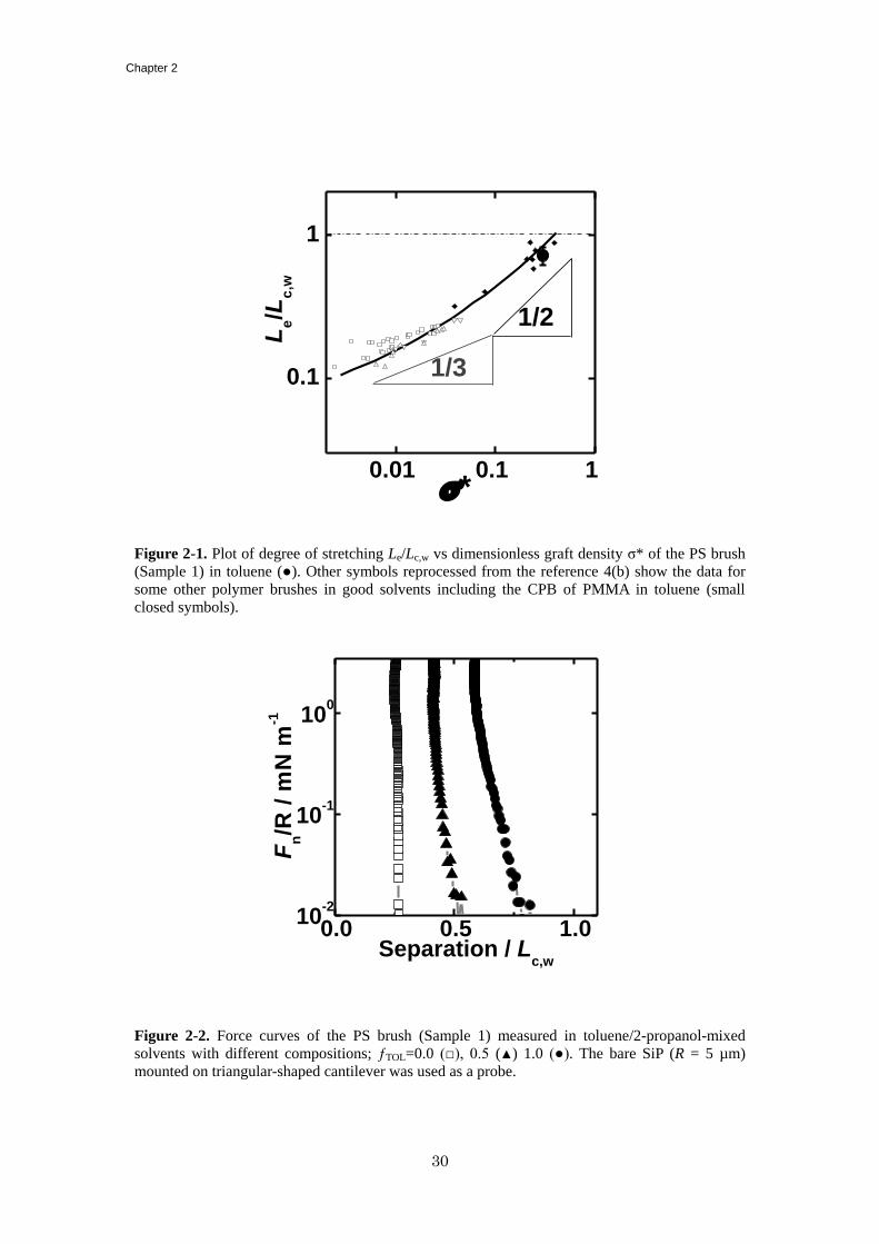
Figure 2-1. Plot of degree of stretching Le/Lc,w vs dimensionless graft density σ* of the PS brush
(Sample 1) in toluene (●). Other symbols reprocessed from the reference 4(b) show the data for
some other polymer brushes in good solvents including the CPB of PMMA in toluene (small
closed symbols).
Figure 2-2. Force curves of the PS brush (Sample 1) measured in toluene/2-propanol-mixed
solvents with different compositions; ƒTOL=0.0 (□), 0.5 (▲) 1.0 (●). The bare SiP (R = 5 µm)
mounted on triangular-shaped cantilever was used as a probe.
0.01 0.1 1
0.1
1
1/2
*
Le/L
c,w
1/3
0.0 0.5 1.010
-2
10-1
100
Fn/R
/ m
N m
-1
Separation / Lc,w
Effect of Solvent Quality and Thereby Swelling State
31
ƒTOL = 1 (pure toluene), 0.5, and 0 (pure 2-propanol). It should be noted that the horizontal axis in
this figure was corrected to the true distance D between the surfaces of the base substrate and the
probe sphere, thus corresponding to the thickness of the PS-brush layer if Fn is detected. In toluene
(at ƒTOL = 1.0), the equilibrium thickness Le, defined as the maximum distance with Fn detectable,
reached 80% of the Lc,w. This force curve indicates not only high stretching of chains but also strong
resistance against compression as Fn steeply increases. This is one of the most important properties
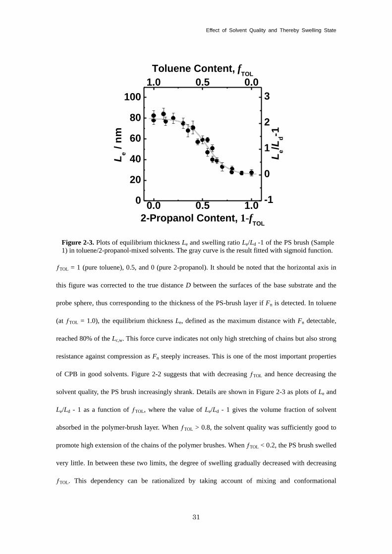
of CPB in good solvents. Figure 2-2 suggests that with decreasing ƒTOL and hence decreasing the
solvent quality, the PS brush increasingly shrank. Details are shown in Figure 2-3 as plots of Le and
Le/Ld - 1 as a function of ƒTOL, where the value of Le/Ld - 1 gives the volume fraction of solvent
absorbed in the polymer-brush layer. When ƒTOL > 0.8, the solvent quality was sufficiently good to
promote high extension of the chains of the polymer brushes. When ƒTOL < 0.2, the PS brush swelled
very little. In between these two limits, the degree of swelling gradually decreased with decreasing
ƒTOL. This dependency can be rationalized by taking account of mixing and conformational
0.0 0.5 1.00
20
40
60
80
100
-1
0
1
2
3
1.0 0.5 0.0
Toluene Content, fTOL
Le /
nm
2-Propanol Content, 1-fTOL
Le/L
d-1
Figure 2-3. Plots of equilibrium thickness Le and swelling ratio Le/Ld -1 of the PS brush (Sample
1) in toluene/2-propanol-mixed solvents. The gray curve is the result fitted with sigmoid function.
Chapter 2
32
entropies; the former causes brush swelling by osmotic pressure and the latter is responsible for the
elastic stress. These two forces are balanced in equilibrium of swelling. The saturated degree of
swelling can presumably be attributed to an rapid increase in conformational entropy (and hence
extension stress) when the graft chain extends to almost full length.
2-3-2. Frictional Property and Mechanism in Mixed Solvents
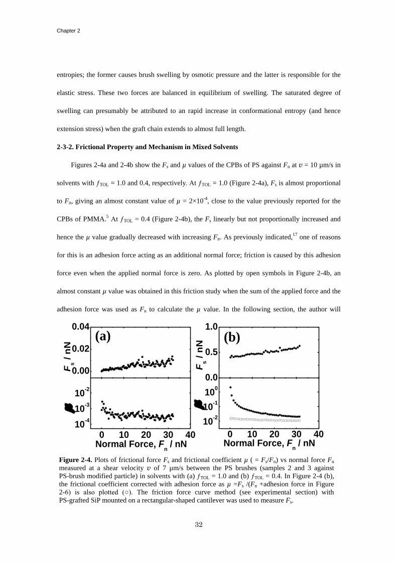
Figures 2-4a and 2-4b show the Fs and µ values of the CPBs of PS against Fn at v = 10 µm/s in
solvents with ƒTOL = 1.0 and 0.4, respectively. At ƒTOL = 1.0 (Figure 2-4a), Fs is almost proportional
to Fn, giving an almost constant value of µ = 2×10⁻⁴
, close to the value previously reported for the
CPBs of PMMA.5 At ƒTOL = 0.4 (Figure 2-4b), the Fs linearly but not proportionally increased and
hence the µ value gradually decreased with increasing Fn. As previously indicated,17
one of reasons
for this is an adhesion force acting as an additional normal force; friction is caused by this adhesion
force even when the applied normal force is zero. As plotted by open symbols in Figure 2-4b, an
almost constant µ value was obtained in this friction study when the sum of the applied force and the
adhesion force was used as Fn to calculate the µ value. In the following section, the author will
Figure 2-4. Plots of frictional force Fs and frictional coefficient µ ( = Fs/Fn) vs normal force Fn
measured at a shear velocity v of 7 µm/s between the PS brushes (samples 2 and 3 against
PS-brush modified particle) in solvents with (a) ƒTOL = 1.0 and (b) ƒTOL = 0.4. In Figure 2-4 (b),
the frictional coefficient corrected with adhesion force as µ =Fs /(Fn +adhesion force in Figure
2-6) is also plotted (○). The friction force curve method (see experimental section) with
PS-grafted SiP mounted on a rectangular-shaped cantilever was used to measure Fs.
0 10 20 30 4010
-4
10-3
10-2
m
Normal Force, Fn / nN
m
Normal Force, Fn / nN
0.00
0.02
0.04
F
s /
nN
Fs /
nN
(a) (b)
0.0
0.5
1.0
0 10 20 30 40
10-2
10-1
100
Effect of Solvent Quality and Thereby Swelling State
33
100
101
102
103
10-4
10-3
10-2
10-1
100
Fri
cti
on
al
Co
eff
icie
nt,
m
Shear Velocity, v / mm s-1
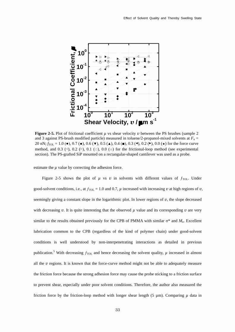
Figure 2-5. Plot of frictional coefficient µ vs shear velocity v between the PS brushes (sample 2
and 3 against PS-brush modified particle) measured in toluene/2-propanol-mixed solvents at Fn =
20 nN; fTOL = 1.0 (●), 0.7 (◆), 0.6 (▼), 0.5 (▲), 0.4 (■), 0.3 (◀), 0.2 (▶), 0.0 (★) for the force curve
method, and 0.3 (◁), 0.2 (▷), 0.1 (◇), 0.0 (☆) for the frictional-loop method (see experimental
section). The PS-grafted SiP mounted on a rectangular-shaped cantilever was used as a probe.
estimate the µ value by correcting the adhesion force.
Figure 2-5 shows the plot of µ vs v in solvents with different values of ƒTOL. Under
good-solvent conditions, i.e., at ƒTOL = 1.0 and 0.7, µ increased with increasing v at high regions of v,
seemingly giving a constant slope in the logarithmic plot. In lower regions of v, the slope decreased
with decreasing v. It is quite interesting that the observed µ value and its corresponding v are very
similar to the results obtained previously for the CPB of PMMA with similar σ* and Mn. Excellent
lubrication common to the CPB (regardless of the kind of polymer chain) under good-solvent
conditions is well understood by non-interpenetrating interactions as detailed in previous
publication.5 With decreasing ƒTOL and hence decreasing the solvent quality, µ increased in almost
all the v regions. It is known that the force-curve method might not be able to adequately measure
the friction force because the strong adhesion force may cause the probe sticking to a friction surface
to prevent shear, especially under poor solvent conditions. Therefore, the author also measured the
friction force by the friction-loop method with longer shear length (5 µm). Comparing µ data in
Chapter 2
34
Figure 2-5, both of these two methods work well to evaluate the friction force correctly with little
differences in results. Interestingly, the data can be categorized into two regimes as a function of
ƒTOL and v. One is the v-dependent regime with almost the same slope, and the other has less
dependence. The lubrication mechanism for these two regimes can be discussed in terms of the
boundary and hydrodynamic lubrications, which were previously proposed for the CPB of PMMA in
a good solvent. For the detailed discussion, the author measured the adhesion force as a function of
ƒTOL and v to take account of attractive interaction between the polymer brushes (see Figure 2-6).
2-3-2-1. Boundary Lubrication
Here, the author describe the boundary lubrication regime, in which the load is carried by the
physical or chemical properties of confronted surfaces including asperities or adhesiveness rather
than those of the lubricant.18
The previous study on the PMMA brushes in toluene revealed that the
degree of interpenetration between graft polymer chains impacts upon the friction;5 the CPB was
demonstrated to have an extremely low value of µ for any applied loads at a low v because the
interpenetration was drastically suppressed due to the entropic effect of highly extended polymer
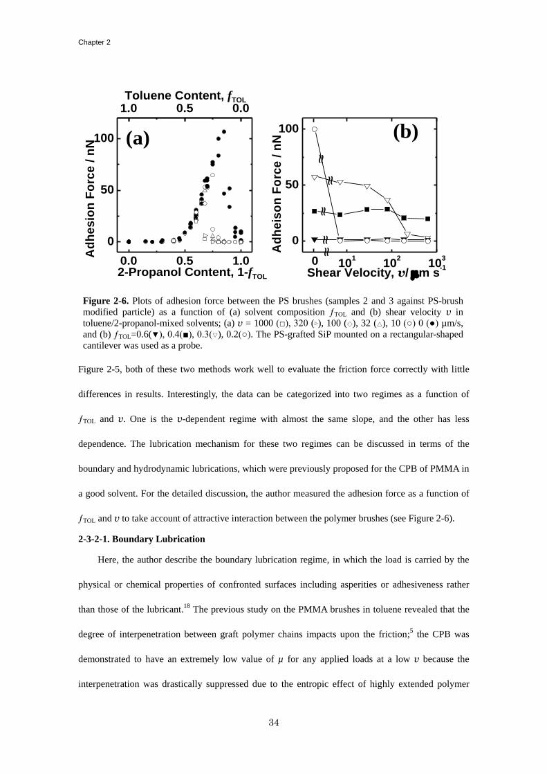
Figure 2-6. Plots of adhesion force between the PS brushes (samples 2 and 3 against PS-brush
modified particle) as a function of (a) solvent composition ƒTOL and (b) shear velocity v in
toluene/2-propanol-mixed solvents; (a) v = 1000 (□), 320 (▷), 100 (◇), 32 (△), 10 (○) 0 (●) µm/s,
and (b) ƒTOL=0.6(▼), 0.4(■), 0.3(▽), 0.2(○). The PS-grafted SiP mounted on a rectangular-shaped
cantilever was used as a probe.
1.0 0.5 0.0
101
102
103
0
50
100
Shear Velocity, v/ mm s-1
~~
~~
~~~
~~
~
(b)
0.0 0.5 1.0
0
50
100
Ad
he
iso
n F
orc
e /
nN
Ad
he
sio
n F
orc
e /
nN
2-Propanol Content, 1-fTOL
0
(a)
Toluene Content, fTOL
Effect of Solvent Quality and Thereby Swelling State
35
chains. The weak v-dependency was previously reported for a system in which the polymer brushes
interpenetrate at a faster rate than the applied shear velocity.19
In this study, a regime with µ on the
order of 10-4
and a weak v-dependency was also observed at a low v regions between the CPBs of
PS under good-solvent conditions, i.e., at ƒTOL = 1.0 and 0.7, where the brush had a highly stretched
conformation ~80% of the Lc,w (as mentioned above) and little adhesion force (see the data plotted
by closed symbols in Figure 2-6a).
In addition to these cases, a weak v-dependency was also observed in solvents with ƒTOL lower
than 0.2 (Figure 2-5). The PS-brush layer is in a glassy state and can no longer function as an
effective lubricant layer. The small v-dependency of µ may be understood by considering Amonton’s
law, in which the kinetic frictional force between solid surfaces bears no relation to the shear
velocity.20
Figure 2-3 suggests that under these conditions, the PS brush is less swollen, giving a
value of Le/Ld - 1 (the solvent fraction in the brush) less than 0.1 at fTOL = 0.2 and almost zero at fTOL
= 0 (pure 2-propanol, non-solvent). The presence of solvent somehow decreases the glass transition
temperature Tg of the polymer due to the reduced barriers for the rotational and transitional motions
of chain segments as the described by the following equation,
1/Tg = W1/Tg1 + W2/Tg2 (2-4)
where W is the weight fraction and the subscripts 1 and 2 refer to the polymer and the diluent,
respectively.21
Using the Tg data of PS (Tg1) as 100 ºC 10
and 2-propanol (Tg2) as -152 ºC,22
the Tg of
the swollen PS brush layer for W1 = 0.9 and hence W2 = 0.1 (at ƒTOL = 0.2) was estimated to be about
30 ºC, which is approximately the room temperature at which the friction measurements were
conducted. This glassy-state brush layer under poor solvent conditions with ƒTOL lower than 0.2
should result in a loss in lubricant efficiency.
Figure 2-6a suggests that the adhesion force remained at ~0 nN for ƒTOL > 0.7 and then
increased with decreasing ƒTOL, reaching a maximum and suddenly decreasing at a critical value
Chapter 2
36
ƒTOL,c. The sudden decrease in adhesion force can be attributed to asperities, i.e., decreasing area of
contact due to the glass transition of the polymer-brush layer. Interestingly, the adhesion force
followed the same ƒTOL dependency up to its maximum at ƒTOL,c independent of v (with and without
shearing), while the ƒTOL,c decreased with increasing v. Of course, the glass transition should be
time-dependent. This is consistent from the data obtained at ƒTOL = 0.3 as shown in Figure 2-6b; the
adhesion force drastically falls at v = 200 µm/s. This is reflected in the data at ƒTOL = 0.3 in Figure
2-5, where the µ value increased with increasing v, approaching an almost constant value beyond v
= 100 mm/s.
2-3-2-2. Hydrodynamic Lubrication
The author now discusses hydrodynamic lubrication, in which the friction force is determined
by the viscosity of solvent rather than the interactions between surfaces. From the viscosity law, the
frictional force in hydrodynamic lubrication can be formulated as follows.23
µ = β ∙ vα (2-5)
where α is the parameter representing the shear-flow distribution in a lubricating layer and β is a
function of viscosity and the effective thickness of the lubricating layer. This lubrication mechanism
is expected to come into play when the shear velocity exceeds a certain value and the friction caused
by boundary lubrication is relatively small. The α parameter is unity for Newtonian fluids but
usually much smaller for polymer solutions behaving as non-Newtonian fluids,23
in which the
entanglement of polymer chains hinders uniform shear-flow distribution of solvent molecules. The
data in Figure 2-5 except for those in the above-mentioned regime of boundary lubrication behaved
in accordance with Equation (2-5). It is notable that the data at different ƒTOL values ranging from
1.0 to 0.3 can be well fitted by a line with almost the same slope in the double logarithmic plot. An
almost constant α value of ca. 0.7 is obtained, even though the degree of swelling changes
significantly as shown in Figure 2-3. Another interesting point is that in those cases, the adhesion
Effect of Solvent Quality and Thereby Swelling State
37
force was detected as shown in Figure 2-6, indicating that the friction caused by this adhesive
interaction should be low enough to achieve hydrodynamic lubrication.
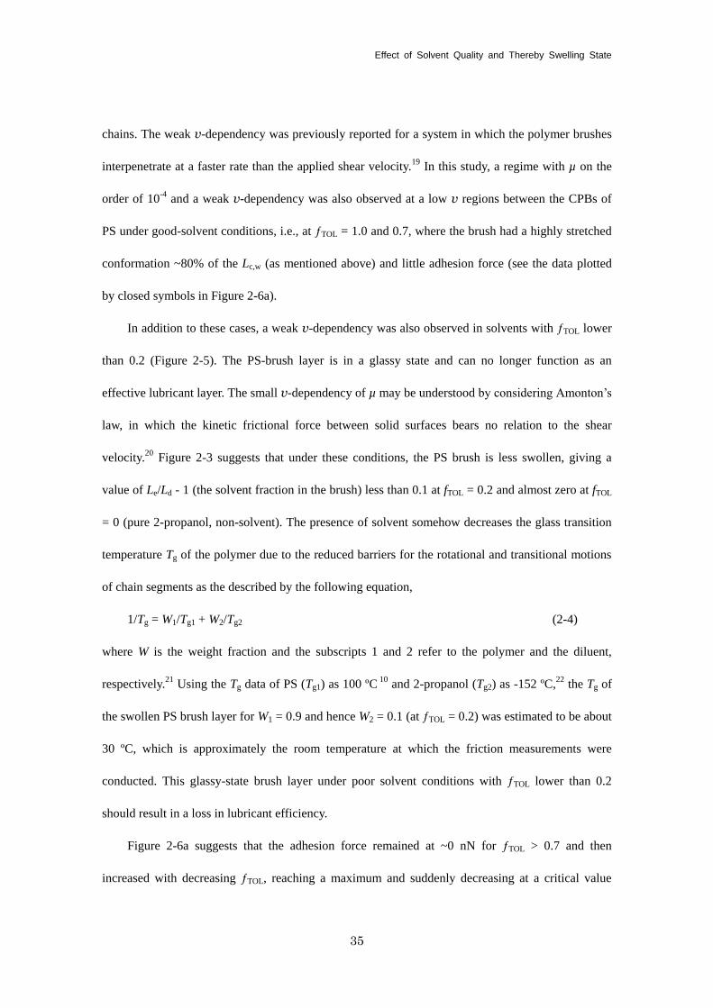
The β parameter, corresponding to intercept of the graph in Figure 2-5, increased with
decreasing ƒTOL, as the above-mentioned fitted line shifted to higher values. This can be explained
by decreasing degree of swelling. In Figure 2-7, the µ values scaled by v-α (α = 0.7) were replotted in
the double logarithmic scale against Le/Ld-1 as a measure of the degree of swelling. This showed a
good linearity, indicating that the β (= µ ∙ v-α) parameter was scaled by the degree of swelling, which
should result in increasing viscosity in the brush and its thickness. Further investigations are
underway to fully characterize this relationship.
Three types of lubricating layers can be proposed for hydrodynamic lubrication; (a) a
pure-solvent layer usually assumed for a system between solid surfaces under high shear conditions,
(b) the swollen brush or its outermost part with a certain depth from the surface, and (c) their mixing.
As shown in Figure 2-6b, a certain amount of adhesion force was observed between the PS-brush
surfaces under reciprocal motion. One may suppose that the interaction around the turning points of
10-1
100
101
10-5
10-4
10-3
10-2
10-1
mv
-
Le/L
d-1
Figure 2-7. Plot of frictional coefficient µ reduced by shear velocity v with parameter α as a
function of degree of swelling Le/Ld-1 for the data in the regime corresponding to hydrodynamic
lubrication.
Chapter 2
38
the reciprocating motion is the origin of this adhesion. However, this possibility was ruled out by the
measurement of frictional loop, which detailed no enhanced interaction around these points. Thus,
the confronted polymer-brush layers interacted with each other even in the regime of hydrodynamic
lubrication. In addition to this consideration, the α value was close to unity when compared with the
systems containing polymer solutions. This indicates that the hydrodynamically lubricating layer
composed by the CPB caused less hindrance to the shear flow of solvent infiltrating into the brush
layer. This might be the characteristic features of the lubrication mechanism of the CPB in addition
to the ultra-low frictional property. These considerations suggest another method of possible
lubrication whereby a pure-solvent layer might be produced between two brush surfaces at much
higher shear velocity.
2-4. Conclusions
The friction/lubrication properties of the CPBs of PS in toluene/2-propanol-mixed solvents
have been studied using an AFM-colloidal-probe technique. The PS brushes prepared in this study
via surface-initiated ATRP were reasonably categorized in the CPB regime, on the basis that the graft
density was sufficiently higher than the critical value for the CPB and that the graft chains were
highly stretched to almost 80% of the contour length in a good solvent (pure toluene). The degree of
swelling of the brush was successfully controlled by varying the solvent composition of
toluene/2-propanol mixture.
The µ data as a function of shear velocity and solvent composition (and hence degree of
swelling) was divided into two regimes corresponding to different lubrication mechanisms. One is
boundary lubrication, in which the chemical or physical property of the outermost surface
determines the frictional force. At low shear velocity in toluene-rich solvents, the boundary
lubrication mechanism afforded µ values that are less dependent on shear velocity and are
Effect of Solvent Quality and Thereby Swelling State
39
exceptionally small (on the order of 10-4
), similar to the previous studies of the CPB of PMMA in
toluene. This had been ascribed to effective suppression of interpenetration between polymer brushes.
Boundary lubrication was also observed in 2-propanol-rich solvents, where the PS-brush layer was
in a glassy state with µ on the order of 0.1 independent of shear velocity.
The second mechanism is hydrodynamic lubrication, in which the viscosity resistance owing to
the solvent-swollen polymer brush dominates the friction. This was observed in a wide range of
solvent compositions except for those in the glassy state. The data in this regime can be described by
the relationship µ = β ∙ vα. An almost constant value of α = 0.7 was obtained and β depended on the
solvent composition and was scaled by the degree of swelling. The measurement of the adhesion
force revealed that the confronted polymer brushes interacted with each other in this regime, which
is different from the usual hydrodynamic lubrication forming a pure-solvent layer. The CPB in
solvents would be an efficient lubricating layer presumably because of its high osmotic pressure.
This work allows for the design of friction/lubrication-controlled materials by taking advantage of
novel properties of the CPBs.
Chapter 2
40
References
(1) (a) Zhang, S. L.; Tsou, A. H.; Li, J. C. M. J. Polym. Sci., Part B: Polym. Phys. 2002, 40,
1530-1537. (b) Zappone, B.; Rosenberg, K. J.; Israelachvili. J. Tribol. Lett. 2007, 26, 191-201.
(c) Hutchings, L. R.; Narrianen, A. P.; Thompson, R. L.; Clarke, N.; Ansari, L. Polym. Int. 2008,
57, 163-170.
(2) (a) Joanny, J. F. Langmuir 1992, 8, 989-995. (b) Klein, J.; Kumacheva, E.; Perahia, D.; Mahalu,
D.; Warburg, S. Faraday Discuss. 1994, 98, 173-188. (c) Grest, G. S. Curr. Opin. Coll.
Interface Sci. 1997, 2, 271-277. (d) Ndoni, S.; Jannasch, P.; Larsen, N. B.; Almdal, K.
Langmuir 1999, 15, 3895-3865. (e) Klein, J.; Kumacheva, E.; Mahalu, D.; Perahia, D.; Fetters,
L. J. Nature 1994, 370, 634-636. (f) Raviv, U.; Giasson, S.; Kampf, N.; Gohy, J. F.; Jerome, R.;
Klein, J. Nature 2003, 425, 163-165. (g) Muller, M.; Lee, S.; Spikes, H. A.; Spencer, N. D.
Tribol. Lett. 2003, 15, 395-405. (h) Yan, X. P.; Perry, S. S.; Spencer, N. D.; Pasche, S.; De Paul,
S. M.; Textor. M.; Lim, M. S. Langmuir 2004, 20, 423-428.
(3) (a) Edmondson, S.; Osborne, V. L.; Huck, W. T. S. Chem. Soc. Rev. 2004, 33, 14-22. (b) Tsujii,
Y.; Ohno, K.; Yamamoto, S.; Goto, A.; Fukuda, T. Adv. Polym. Sci. 2006, 197, 1-45. (c) Barbey,
R.; Lavanant, L.; Paripovic, D.; Schuwer, N.; Sugnaux, C.; Tugulu, S.; Klok, H. A. Chem. Rev.
2009, 109, 5437-5527.
(4) (a) Yamamoto, S.; Ejaz, M.; Tsujii, Y.; Matsumoto, M.; Fukuda, T. Macromolecules 2000, 33,
5602-5607. (b) Yamamoto, S.; Ejaz, M.; Tsujii, Y.; Fukuda, T. Macromolecules 2000, 33,
5608-5612.
(5) Tsujii, Y.; Okayasu, K.; Nomura, A.; Ohno, K.; Fukuda, T. submitted.
(6) (a) Sakata, H.; Kobayashi, M.; Otsuka, H.; Takahara, A. Polym. J. 2005, 37, 767-775. (b)
Kobayashi, M.; Terayama, Y.; Hosaka, N.; Kaido, M.; Suzuki, A.; Yamada, N.; Torikai, N.;
Ishihara, K.; Takahara, A. Soft Matter 2007, 3, 740-746. (c) Kobayashi, M.; Takahara, A. Chem.
Effect of Solvent Quality and Thereby Swelling State
41
Rec. 2010, 10, 208-216. (d) Ishikawa, T.; Kobayashi, M.; Takahara, A. ACS Appl. Mater.
Interfaces 2010, 2, 1120-1128.
(7) Bhushan, B. Introduction to Tribology; John Wiley & Sons Inc: New York, 2002.
(8) Ohno, K.; Morinaga, T.; Koh, K.; Tsujii, Y.; Fukuda, T. Macromolecules 2005, 38, 2137-2142.
(9) (a) Husseman, M.; Malmstrom, E. E.; McNamara, M.; Mate, M.; Mecerreyes, D.; Benoit, D.
G.; Hedrick, J. L.; Mansky, P.; Huang, E.; Russell, T. P.; Hawker, C. J. Macromolecules 1999,
32, 1424-1431. (b) Von Werne, T.; Patten, T. E. J. Am. Chem. Soc. 1999, 121, 7409-7410. (c)
Pyun, J.; Jia, S.; Kowalewski, T.; Patterson, G. D.; Matyjaszewski, K. Macromolecules 2003,
36, 5094-5104. (d) Blomberg, S.; Ostberg, S.; Harth, E.; Bosman, A. W.; Van Hor, B.; Hawker,
C. J. J. Polym. Sci., Part A: Polym. Sci. 2002, 40, 1309-1320. (e) Tsujii, Y.; Ejaz, M.; Sato, K.;
Goto, A.; Fukuda, T. Macromolecules 2001, 34, 8872-8878. (f) Morinaga, T.; Ohkura, M.; Ohno,
K.; Tsujii, Y.; Fukuda, T. Macromolecules 2007, 40, 1159-1164.
(10) Brandrup, J.; Immergut, E. H.; Grulke, E. A., Eds.; Polymer Handbook; John Wiley & Sons Inc:
New York, 1999.
(11) Ducker, W. A.; Senden, T. J.; Pashley, R. M. Langmuir 1992, 8, 1831-1836.
(12) Ogletree, D. F.; Carpick, R. W.; Salmeron, M. Rev. Sci. Intrum. 1996, 67, 3298-3306.
(13) Meyer, G.; Amer, N. M. Appl. Phys. Lett. 1990, 57, 2089-2091.
(14) Green, C. P.; Lioe, H.; Cleveland, J. P.; Proksch R.; Mulvaney, P.; Sader, J. E. Rev. Sci. Inst.
2004, 75, 1988-1966.
(15) (a) Taunton, H. J.; Toprakcioglu, C.; Fetters, L. J.; Klein, J. Macromolecules 1990, 23, 571-580.
(b) Courvoisier, A.; Isel, F.; Francois, J.; Maaloum, M. Langmuir 1998, 14, 3727-3729.
(16) (a) Oshea, S. J.; Welland. M. E.; Rayment, T. Langmuir 1993, 9, 1826-1835. (b) Shim, D. F. K.;
Cates, M. E. J. Phys. (Paris) 1989, 50, 3535-3551.
(17) Butt, H. J.; Kappl, M. Surface and Interfacial Forces; Wiley-VCH: Weinheim, 2006.
Chapter 2
42
(18) (a) Kaneko, D.; Oshikawa, M.; Yamaguchi, T.; Gong, J. P.; Doi, M. J. Phys. Soc. Jpn. 2007, 76,
043601. (b) Wang, W. Z.; Hu, Y. Z.; Liu, Y. C.; Wang, H. Tribol. Int. 2007, 40, 687-693.
(19) Tadmor, R.; Janik, J.; Klein, J.; Fetters, L. J. Phys. Rev. Lett. 2003, 91, 115503.
(20) Amonton, G. Mem. del’ Academie Royale A 1699, 275-282.
(21) (a) Fox, T. G. Bull. Am. Phys. Soc. 1956, 1, 123. (b) Nielson, L. E. Mechanical Properties of
Polymers; Reinhold: New York, 1962. (c) Sung, Y. K.; Gregonis, D. E.; Russell, G. A.; Andrade,
J. D. Polymer 1978, 19, 1362-1363.
(22) Faucher, J. A.; Koleske, J. V. Phys. Chem. Glasses 1966, 7, 202.
(23) Barnes, H. A.; Hutton, J. F.; Walters, K. An Introduction to Rheology; Elsevier: Amsterdam,
1989.
43
Chapter 3
Lubrication Mechanism of Concentrated Polymer Brushes in Solvents: Effect of Solvent
Viscosity
3-1. Introduction
The suppression of interpenetration and hence the decrease of friction in the boundary
lubrication regime manifested the other mechanism of lubrication even at high loads, that is
hydrodynamic lubrication. In this regime, the viscosity resistance between and/or in the
solvent-swollen polymer brushes dominates the friction, giving v-dependency on µ. In Chapter 2, the
author studied the CPB of PS in a mixture of good/non solvents in which the solvent quality was
controlled. It was demonstrated that under the hydrodynamic lubrication regime, the confronted
polymer brushes still had some interaction and that the frictional property could be scaled by the
degree of swelling. This is a new mechanism characteristic to the CPB, in contrast to the usual
hydrodynamic lubrication forming a pure-solvent layer. It may be expected that the hydrodynamic
lubrication will be affected by viscosity and brush height concurrently. In order to test this
assumption and also to clarify the mechanism of hydrodynamic lubrication for the CPB, the author
will investigate the frictional property of the CPB of PMMA in ionic liquids (ILs) which have higher
viscosities than typical organic solvents such as toluene.
Recently, ILs have attracted much attention as green solvents because of their characteristic
properties such as nonvolatility, noncombustibility, wide solvent-temperature ranges, and
electrochemical stability.1 ILs can dissolve various kinds of chemical additives, including some
polymers, by suitably designing the molecular structure of anionic and cationic species.2 ILs usually
have higher viscosities than general organic solvents of equivalent molecular weight because of
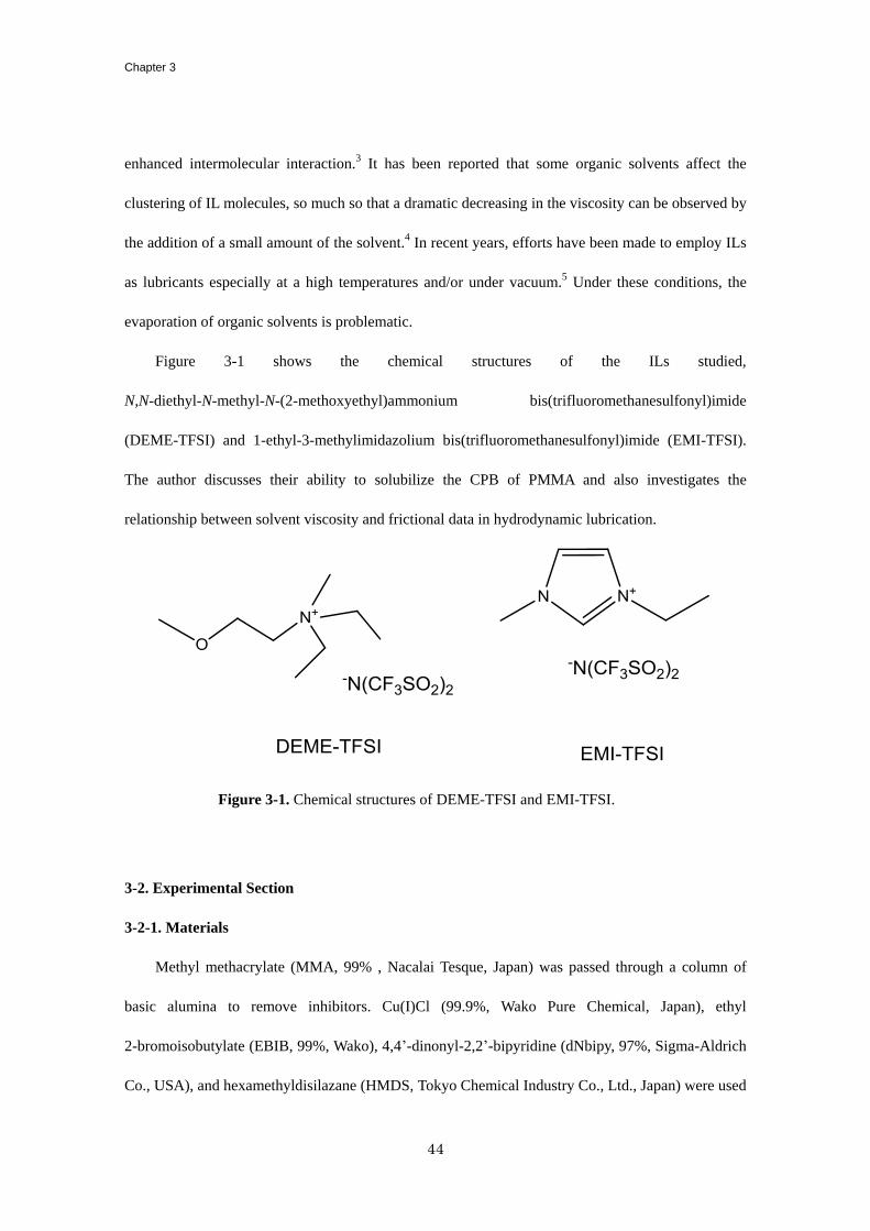
Chapter 3
44
enhanced intermolecular interaction.3 It has been reported that some organic solvents affect the
clustering of IL molecules, so much so that a dramatic decreasing in the viscosity can be observed by
the addition of a small amount of the solvent.4 In recent years, efforts have been made to employ ILs
as lubricants especially at a high temperatures and/or under vacuum.5 Under these conditions, the
evaporation of organic solvents is problematic.
Figure 3-1 shows the chemical structures of the ILs studied,
N,N-diethyl-N-methyl-N-(2-methoxyethyl)ammonium bis(trifluoromethanesulfonyl)imide
(DEME-TFSI) and 1-ethyl-3-methylimidazolium bis(trifluoromethanesulfonyl)imide (EMI-TFSI).
The author discusses their ability to solubilize the CPB of PMMA and also investigates the
relationship between solvent viscosity and frictional data in hydrodynamic lubrication.
3-2. Experimental Section
3-2-1. Materials
Methyl methacrylate (MMA, 99% , Nacalai Tesque, Japan) was passed through a column of
basic alumina to remove inhibitors. Cu(I)Cl (99.9%, Wako Pure Chemical, Japan), ethyl
2-bromoisobutylate (EBIB, 99%, Wako), 4,4’-dinonyl-2,2’-bipyridine (dNbipy, 97%, Sigma-Aldrich
Co., USA), and hexamethyldisilazane (HMDS, Tokyo Chemical Industry Co., Ltd., Japan) were used
Figure 3-1. Chemical structures of DEME-TFSI and EMI-TFSI.
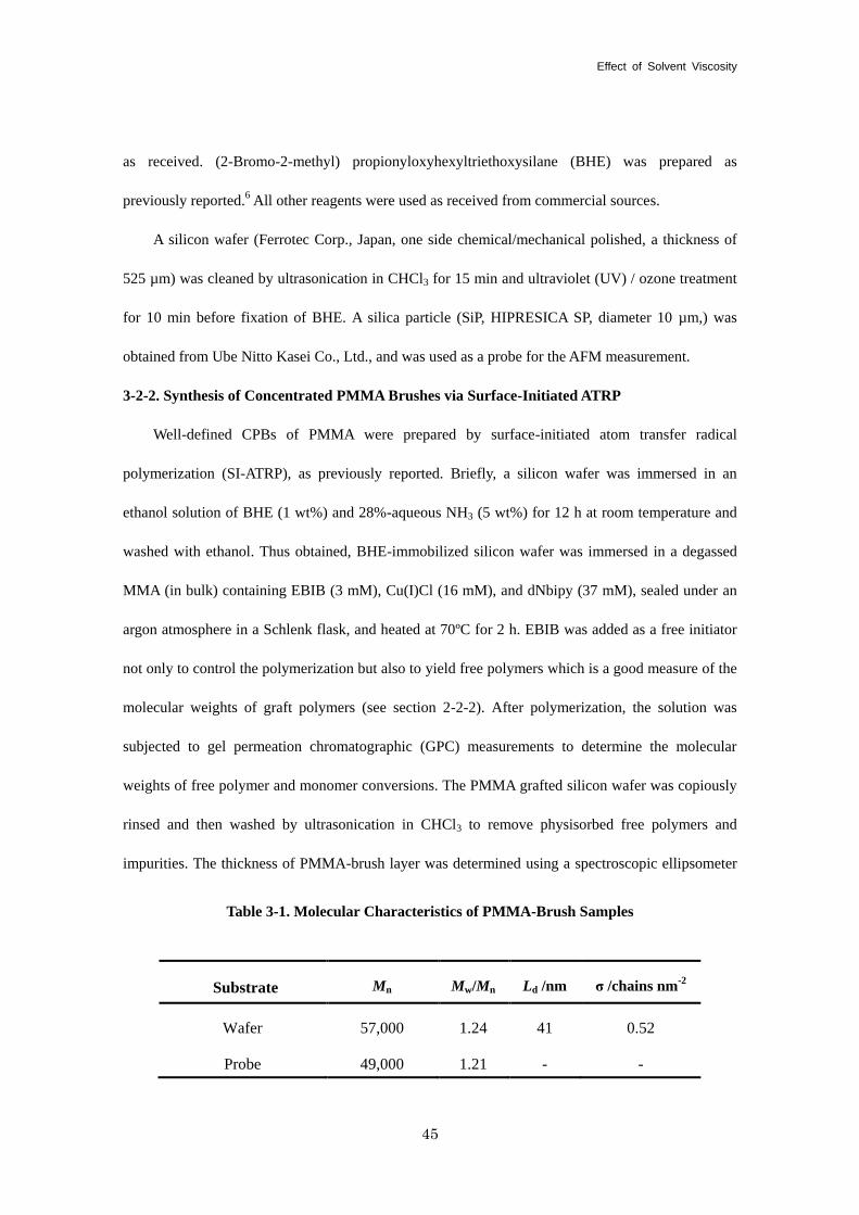
Effect of Solvent Viscosity
45
as received. (2-Bromo-2-methyl) propionyloxyhexyltriethoxysilane (BHE) was prepared as
previously reported.6 All other reagents were used as received from commercial sources.
A silicon wafer (Ferrotec Corp., Japan, one side chemical/mechanical polished, a thickness of
525 µm) was cleaned by ultrasonication in CHCl3 for 15 min and ultraviolet (UV) / ozone treatment
for 10 min before fixation of BHE. A silica particle (SiP, HIPRESICA SP, diameter 10 µm,) was
obtained from Ube Nitto Kasei Co., Ltd., and was used as a probe for the AFM measurement.
3-2-2. Synthesis of Concentrated PMMA Brushes via Surface-Initiated ATRP
Well-defined CPBs of PMMA were prepared by surface-initiated atom transfer radical
polymerization (SI-ATRP), as previously reported. Briefly, a silicon wafer was immersed in an
ethanol solution of BHE (1 wt%) and 28%-aqueous NH3 (5 wt%) for 12 h at room temperature and
washed with ethanol. Thus obtained, BHE-immobilized silicon wafer was immersed in a degassed
MMA (in bulk) containing EBIB (3 mM), Cu(I)Cl (16 mM), and dNbipy (37 mM), sealed under an
argon atmosphere in a Schlenk flask, and heated at 70ºC for 2 h. EBIB was added as a free initiator
not only to control the polymerization but also to yield free polymers which is a good measure of the
molecular weights of graft polymers (see section 2-2-2). After polymerization, the solution was
subjected to gel permeation chromatographic (GPC) measurements to determine the molecular
weights of free polymer and monomer conversions. The PMMA grafted silicon wafer was copiously
rinsed and then washed by ultrasonication in CHCl3 to remove physisorbed free polymers and
impurities. The thickness of PMMA-brush layer was determined using a spectroscopic ellipsometer
Table 3-1. Molecular Characteristics of PMMA-Brush Samples
Substrate Mn Mw/Mn Ld /nm σ /chains nm-2
Wafer 57,000 1.24 41 0.52
Probe 49,000 1.21 - -
Chapter 3
46
(M-2000U, J. A. Woolam, Lincoln, NE). For the synthesis of the CPB of PMMA on a SiP, the same
procedure followed except that the SiP concentration maintained at ~0.5 wt% for all steps. Table 3-1
lists the characteristics of the CPBs of PMMA studied in this paper. The number-average molecular
weight, Mn, and the polydispersity index, Mw/Mn, are those of the free polymer analyzed by GPC
calibrated with PMMA standards. The graft density σ was calculated from Mn, Ld, the bulk density of
a PMMA film ρ (= 1.19 g/cm3),
7 and Avogadro constant NA, using σ = ρLdNA/Mn.
3-2-3. Hydrophobic Treatment of Silicon Wafer and SiP
Hydrophobic treatment of a silicon wafer was performed according to the method of Chen et
al.8 a silicon wafer was immersed in a mixture of HMDS (10 wt%) and toluene (90 wt%), heated at
110ºC for 5 h, and then rinsed with chloroform. The same treatment was applied to a SiP with a
concentration as low as ~0.3 wt%. After the treatment, the modified SiP was repeatedly washed with
chloroform and stored in it prior to use.
3-2-4.AFM Force Measurements
Normal and frictional forces were measured by an atomic force microscope (AFM) (JPK
Instruments Inc., Germany, NanoWizard) equipped with a rectangular-shaped cantilever (Olympus
Optical Co., Ltd., Japan, OMCL-RC800, vertical spring constant, kn = 0.1 N/m). A brush-modified or
hydrophobized SiP was attached on the cantilever with a two-component epoxy resin adhesive. The
detailed procedures are given in section 2-2-3.
3-2-5. Viscosities of ILs
The viscosities of DEME-TFSI and EMI-TFSI (Table 3-2) were determined with a rheometer
(Malvern Instruments., UK, CVOR 150) equipped with a temperature control unit (Malvern
Instruments, Melts Oven) and a cone/plate geometry with a diameter of 25 mm.
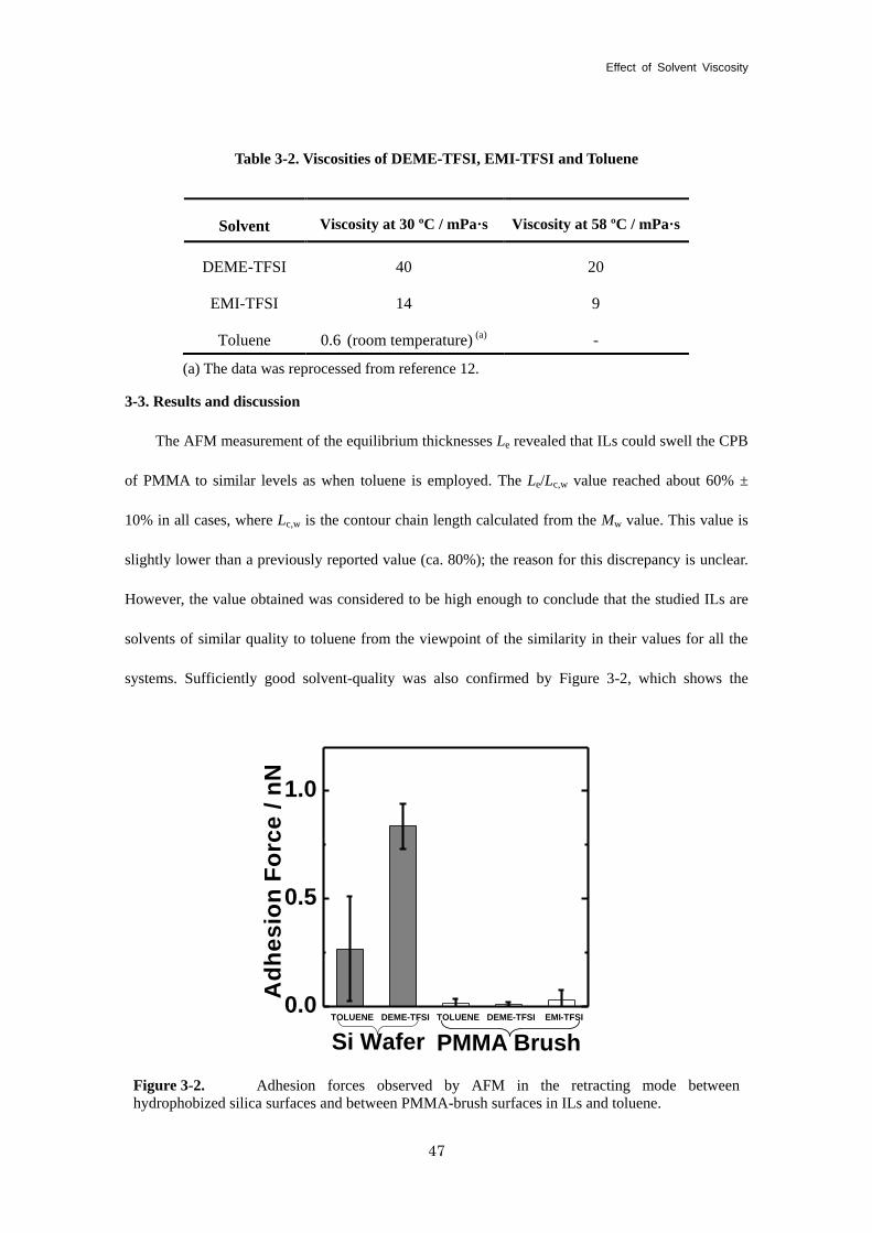
Effect of Solvent Viscosity
47
3-3. Results and discussion
The AFM measurement of the equilibrium thicknesses Le revealed that ILs could swell the CPB
of PMMA to similar levels as when toluene is employed. The Le/Lc,w value reached about 60% ±
10% in all cases, where Lc,w is the contour chain length calculated from the Mw value. This value is
slightly lower than a previously reported value (ca. 80%); the reason for this discrepancy is unclear.
However, the value obtained was considered to be high enough to conclude that the studied ILs are
solvents of similar quality to toluene from the viewpoint of the similarity in their values for all the
systems. Sufficiently good solvent-quality was also confirmed by Figure 3-2, which shows the
Table 3-2. Viscosities of DEME-TFSI, EMI-TFSI and Toluene
Solvent Viscosity at 30 ºC / mPa·s Viscosity at 58 ºC / mPa·s
DEME-TFSI 40 20
EMI-TFSI 14 9
Toluene 0.6 (room temperature) (a) -
(a) The data was reprocessed from reference 12.
TOLUENE DEME-TFSI TOLUENE DEME-TFSI EMI-TFSI0.0
0.5
1.0
PMMA Brush
Ad
he
sio
n F
orc
e /
nN
Si Wafer
Figure 3-2. Adhesion forces observed by AFM in the retracting mode between
hydrophobized silica surfaces and between PMMA-brush surfaces in ILs and toluene.
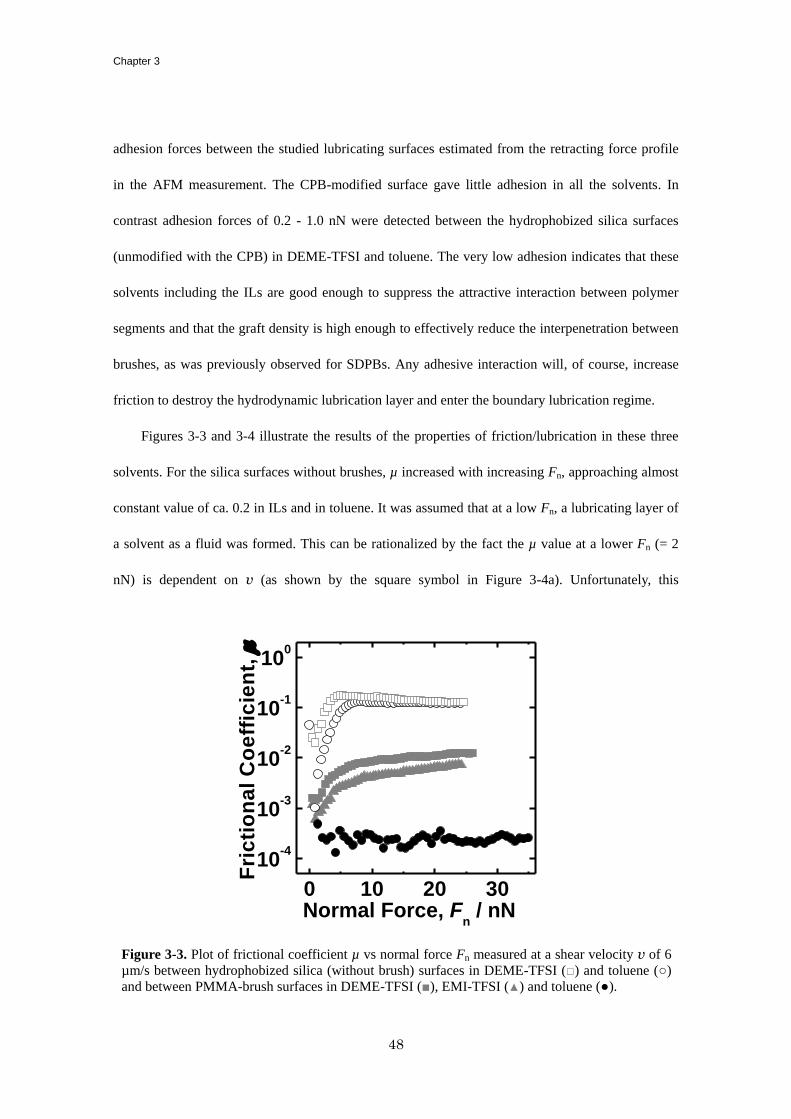
Chapter 3
48
adhesion forces between the studied lubricating surfaces estimated from the retracting force profile
in the AFM measurement. The CPB-modified surface gave little adhesion in all the solvents. In
contrast adhesion forces of 0.2 - 1.0 nN were detected between the hydrophobized silica surfaces
(unmodified with the CPB) in DEME-TFSI and toluene. The very low adhesion indicates that these
solvents including the ILs are good enough to suppress the attractive interaction between polymer
segments and that the graft density is high enough to effectively reduce the interpenetration between
brushes, as was previously observed for SDPBs. Any adhesive interaction will, of course, increase
friction to destroy the hydrodynamic lubrication layer and enter the boundary lubrication regime.
Figures 3-3 and 3-4 illustrate the results of the properties of friction/lubrication in these three
solvents. For the silica surfaces without brushes, µ increased with increasing Fn, approaching almost
constant value of ca. 0.2 in ILs and in toluene. It was assumed that at a low Fn, a lubricating layer of
a solvent as a fluid was formed. This can be rationalized by the fact the µ value at a lower Fn (= 2
nN) is dependent on v (as shown by the square symbol in Figure 3-4a). Unfortunately, this
0 10 20 30
10-4
10-3
10-2
10-1
100
Fri
cti
on
al
Co
eff
icie
nt,
m
Normal Force, Fn / nN
Figure 3-3. Plot of frictional coefficient µ vs normal force Fn measured at a shear velocity v of 6
µm/s between hydrophobized silica (without brush) surfaces in DEME-TFSI (□) and toluene (○)
and between PMMA-brush surfaces in DEME-TFSI (■), EMI-TFSI (▲) and toluene (●).
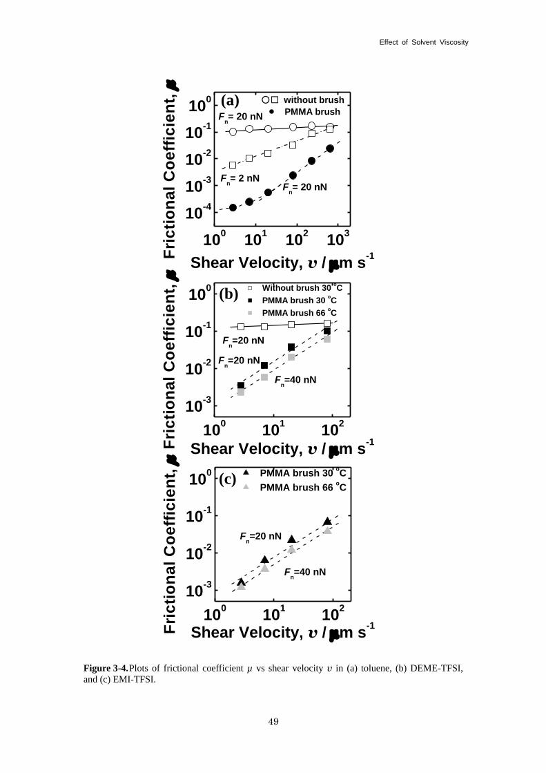
Effect of Solvent Viscosity
49
Figure 3-4. Plots of frictional coefficient µ vs shear velocity v in (a) toluene, (b) DEME-TFSI,
and (c) EMI-TFSI.
100
101
102
103
10-4
10-3
10-2
10-1
100
Fn= 20 nN
Fn= 20 nN
Fn= 2 nN
○ □ without brush
PMMA brush
Fri
cti
on
al
Co
eff
icie
nt,
m
Shear Velocity, v / mm s-1
(a)
100
101
102
10-3
10-2
10-1
100
Fn=20 nN
Fn=40 nN
Fn=20 nN
Without brush 30 oC
PMMA brush 30 oC
PMMA brush 66 oC
(b)
Fri
cti
on
al
Co
eff
icie
nt,
m
Shear Velocity, v / mm s-1
100
101
102
10-3
10-2
10-1
100
Fn=40 nN
Fn=20 nN
PMMA brush 30 oC
PMMA brush 66 oC
(c)
Fri
cti
on
al
Co
eff
icie
nt,
m
Shear Velocity, v / mm s-1
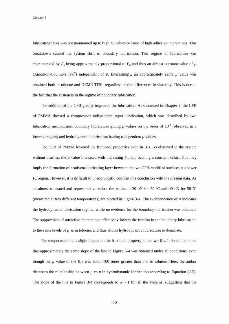
Chapter 3
50
lubricating layer was not maintained up to high Fn values because of high adhesive interactions. This
breakdown caused the system shift to boundary lubrication. This regime of lubrication was
characterized by Fs being approximately proportional to Fn and thus an almost constant value of µ
(Amonton-Coulmb’s law9) independent of v. Interestingly, an approximately same µ value was
obtained both in toluene and DEME-TFSI, regardless of the differences in viscosity. This is due to
the fact that the system is in the regime of boundary lubrication.
The addition of the CPB greatly improved the lubrication. As discussed in Chapter 2, the CPB
of PMMA showed a compression-independent super lubrication, which was described by two
lubrication mechanisms: boundary lubrication giving µ values on the order of 10-4
(observed in a
lower-v region) and hydrodynamic lubrication having v-dependent µ values.
The CPB of PMMA lowered the frictional properties even in ILs. As observed in the system
without brushes, the µ value increased with increasing Fn, approaching a constant value. This may
imply the formation of a solvent-lubricating layer between the two CPB-modified surfaces at a lower
Fn region. However, it is difficult to unequivocally confirm this conclusion with the present data. As
an almost-saturated and representative value, the µ data at 20 nN for 30 ºC and 40 nN for 58 ºC
(measured at two different temperatures) are plotted in Figure 3-4. The v-dependency of µ indicates
the hydrodynamic lubrication regime, while no evidence for the boundary lubrication was obtained.
The suppression of attractive interactions effectively lowers the friction in the boundary lubrication,
to the same levels of µ as in toluene, and thus allows hydrodynamic lubrication to dominate.
The temperature had a slight impact on the frictional property in the two ILs. It should be noted
that approximately the same slope of the line in Figure 3-4 was obtained under all conditions, even
though the µ value of the ILs was about 100 times greater than that in toluene. Here, the author
discusses the relationship between µ vs v in hydrodynamic lubrication according to Equation (2-5).
The slope of the line in Figure 3-4 corresponds to α ~ 1 for all the systems, suggesting that the
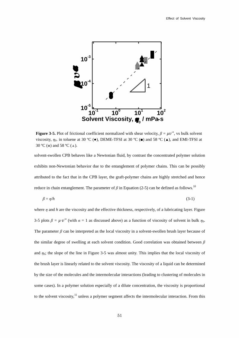
Effect of Solvent Viscosity
51
solvent-swollen CPB behaves like a Newtonian fluid, by contrast the concentrated polymer solution
exhibits non-Newtonian behavior due to the entanglement of polymer chains. This can be possibly
attributed to the fact that in the CPB layer, the graft-polymer chains are highly stretched and hence
reduce in chain entanglement. The parameter of β in Equation (2-5) can be defined as follows.10
β = η/h (3-1)
where η and h are the viscosity and the effective thickness, respectively, of a lubricating layer. Figure
3-5 plots β = µ∙v-α (with α = 1 as discussed above) as a function of viscosity of solvent in bulk η0.
The parameter β can be interpreted as the local viscosity in a solvent-swollen brush layer because of
the similar degree of swelling at each solvent condition. Good correlation was obtained between β
and η0; the slope of the line in Figure 3-5 was almost unity. This implies that the local viscosity of
the brush layer is linearly related to the solvent viscosity. The viscosity of a liquid can be determined
by the size of the molecules and the intermolecular interactions (leading to clustering of molecules in
some cases). In a polymer solution especially of a dilute concentration, the viscosity is proportional
to the solvent viscosity,11
unless a polymer segment affects the intermolecular interaction. From this
10-1
100
101
10210
-5
10-4
10-3
m v
-
Solvent Viscosity, h0 / mPa s
1
Figure 3-5. Plot of frictional coefficient normalized with shear velocity, β = µv-α, vs bulk solvent
viscosity, η0. in toluene at 30 ºC (●), DEME-TFSI at 30 ºC (■) and 58 ºC (▲), and EMI-TFSI at
30 ºC (■) and 58 ºC (▲).
Chapter 3
52
point of view, the observed proportionality is a special case, presumably due to the solvent-swollen
CPB possessing a highly stretched-chain conformation. The above-mentioned data do not show
clustering to have a significant effect. The formation of a lubricating layer in concert with the
solvent-swollen CPB layer in the IL system can be readily explained in terms of the hydrodynamic
lubrication mechanism.
3-4. Conclusions
The AFM-microtribologic technique was used to investigate the frictional properties of PMMA
CPBs in highly viscous ILs (DEME-TFSI and EMI-TFST) and toluene, which are all good solvents
for PMMA. In the ILs, little adhesive interaction between the brush surfaces was observed, which
caused a dramatic decrease in the frictional coefficient µ in the boundary lubrication regime to
values on the order of 10-4
as was the case in toluene. This decrease allowed the hydrodynamic
lubrication mechanism to dominate. In this regime, the v-dependence of µ followed power-law
scaling with an value close to unity. It was suggested that the thus produced lubricating layers
should have similar thicknesses in toluene as well as ILs and that the frictional property could be
simply related to the solvent viscosity. These friction/lubrication properties can be attributed to the
unique features of the CPBs in a good solvent: the polymer chains are highly stretched due to high
osmotic pressure. The author has suggested that the local viscosity of the lubricating layer on or in
the brushes is proportional to that of the solvent in bulk. Finally, the author concludes that the
addition of the CPB layer improved the friction even in ILs, where the hydrodynamically lubricating
layer was successfully produced and maintained under all the conditions studied. The combination of
ILs and CPB may lead to the development of a novel route toward the control of lubrication in
practical applications.
Effect of Solvent Viscosity
53
References
(1) (a) Dupont, J. ; de Souza, R. F. ; Suarez P. A. Z. Chem. Rev. 2002, 102, 3667-3691. (b)
Kirchner, B., Eds.; Ionic Liquids; Springer: Heidelberg, 2007. (c) Freemantle, M. An
Introduction to Ionic Liquids; Royal Society of Chemistry: London, 2010.
(2) (a) Carmichael, A. J.; Haddleton, D. M.; Bon, S. F. A.; Seddon, K. R. Chem. Commun. 2000, 14,
1237-1238. (b) Biedron, T.; Kubisa, P. Macromol. Rap. Comm. 2001, 22, 1237-1242. (c) Kubisa,
P. Prog. Polym. Sci. 2004, 29. 3-12. (d) Susan, M. A.; Kaneko, T.; Noda, A.; Watanabe, M. J.
Am. Chem. Soc. 2005, 127, 4976-4983.
(3) (a) Carper, W. R.; Pflug, J. L.; Elias, A. M.; Wilkes, J. S. J. Phys. Chem. 1992, 96, 3828-3833.
(b) Fuller, J.; Carlin, R. T.; Delong, H. C.; Haworth, D. Chem. Commun. 1994, 3, 299-300. (c)
Elaiwi, A.; Hitchcock, P. B.; Seddon, K. R.; Srinivasan, N.; Tan, Y. M.; Welton, T.; Zora, J. A.
Dalton Trans. 1995, 21, 3467-3472. (d) Suarez, P. A. Z.; Einloft, S.; Dullius, J. E. L.; de Souza,
R. F.; Dupont, J. J. Chim. Phys. 1998, 95, 1626-1639.
(4) (a) Seddon, K. R.; Stark, A.; Torres, M. J. Pure Appl. Chem. 2000, 72, 2275-2287. (b)
Huddleston, J. G.; Visser, A. E.; Reichert, W. M.; Willauer, H. D.; Broker, G. A.; Rogers, R. D.
Green Chem. 2001, 3, 156-164.
(5) (a) Wang, H. Z.; Lu, Q. M.; Ye, W. M.; Cui, Z. J. Wear 2004, 256, 44-48. (b) Kamimura, H.;
Kubo, T.; Minami, I.; Mori, S. Tribol. Int. 2007, 40, 620-625. (c) Sanes, J.; Carrion, F. J.;
Bermudez, M. D.; Martinez-Nicolas, G. Tribol. Lett. 2006, 21, 121-123. (d) Bhushan, B.;
Palacio, M.; Kinzig, B. J. Coll. Int. Sci. 2008, 317, 275-287.
(6) Ohno, K.; Morinaga, T.; Koh, K.; Tsujii, Y.; Fukuda, T. Macromolecules 2005, 38, 2137-2142.
(7) Brandrup, J.; Immergut, E. H.; Grulke, E. A., Eds.; Polymer Handbook; John Wiley & Sons Inc:
New York, 1999.
(8) Chen, Y. K.; Chang, K. C.; Wu, K. Y.; Tsai, Y. L.; Lu, J. S.; Chen, H. Appl. Surf. Sci. 2009, 255,
Chapter 3
54
8634-8642.
(9) Amonton, G. Mem. del’Academie Royale A 1699, 275-282
(10) Barnes, H. A.; Hutton, J. F.; Walters, K. An Introduction to Rheology; Elsevier: Amsterdam,
1989.
(11) Atkins, P. W. Physical Chemistry Sixth Edition; Oxford University Press: Oxford, 1978.
(12) Santos, F.; de Castro, C.; Dymond, J.; Dalaouti, N., Assael, M., Nagashima, A. J. Phys. Chem.
Ref. Data 2006, 35, 1-8.
55
Chapter4
Super Lubrication and its Mechanism between Immiscible Concentrated Polymer Brushes
in Good Solvent
4-1. Introduction
In Chapter 2, the author found out the boundary and hydrodynamic lubrication features in the
friction of CPBs. The friction force in hydrodynamic lubrication is determined by the effective
viscosity and thickness of lubricating layer. The author revealed that the friction force of CPBs in
hydrodynamic lubrication state was scaled with the degree of swelling (Chapter 2) and viscosity of
swelling solvents of brush layer (Chapter 3). Meanwhile, the boundary lubrication is the lubrication
state in which the interaction between confronted friction surfaces determines the friction force. The
strong resistance of brush layer against mixing drastically reduces the friction force in boundary
lubrication. The boundary and hydrodynamic lubrication features can be distinguished from the
v-dependence on friction force; the friction force in hydrodynamic lubrication depends
logarithmically on the shear velocity obeying the definition of viscosity, while the shear velocity has
a less significant effect on the friction force in boundary lubrication.
As mentioned above, CPBs successfully achieved super lubrication by restriction of
interpenetration of graft polymer chains. The friction mechanism of super lubrication of CPB would
be classified into boundary lubrication in the view point of graft chains related surface interaction.
However, the polymer brush surface interaction is still not clearly evaluated and the relevance with
frictional property of polymer brushes remains undetermined. Actually, the graft polymer chains of
CPBs have certain chain length distributions that would allow a little interpenetration of polymer
chains at free ends. This small interpenetration would be inevitable even if the CPBs are fabricated
through ideal LRP process.1 It can be considered that small quantity of contamination at free ends of
graft chain determines the value of µ of 10-4
order of super lubrication of CPB. Further reduction of
Chapter 4
56
frictional coefficient, especially in boundary lubrication state, is expected by restricting the
contamination more efficiently.
Introduction of repulsive interaction on graft polymer chains is an approach to suppress the
contamination. Using CPBs of dissimilar polymers would be one way to enhance the repulsive effect.
As it is known well, dissimilar polymers are often immiscible because the mixing entropy of
dissimilar polymer is quite lower than low molecular weight solvent.2 Such an immiscible character
would inhibit undesired interpenetration for lubricating polymeric materials to improve their
frictional property, but that have not previously investigated so far. In this study, the frictional
property between CPBs of dissimilar polymers (PMMA and PS) was studied and compared to that of
similar CPBs and SDPBs. The interaction between approached brush layers was also simulated with
self-consistent field (SCF) calculation based on dynamic mean-field approximation to reveal the
appearance of polymer chains interpenetration. The author will discuss the boundary lubrication
feature of the friction of CPBs in the relevance of graft chains interpenetration.
4-2. Experimental Section
4-2-1. Materials
Silicon wafer (Ferrotec Corp., Japan, thickness 0.5 mm) was used as substrates for polymer
brush surfaces. Silica particle (SiP, HIPRESICA SP, diameter 10 µm) obtained from Ube Nitto Kasei
Co., Ltd., was used as prove of AFM for friction measurement. CPBs of PMMA and PS were
fabricated on the surfaces of silicon wafer and SiP by surface-initiated ATRP, as described in Chapter
2 and Chapter 3. The characteristics of polymer brushes used in this study were summarized in Table
4-1. Toluene (Wako Pure Chemicals., 99%, spectroscopic grade) was used as solvent for friction
measurement.
4-2-2. AFM Measurements
Normal and friction forces were measured by an atomic force microscope (AFM) (JPK
Instruments Inc., Germany, NanoWizard) equipped with a rectangular-shaped cantilever (Olympus
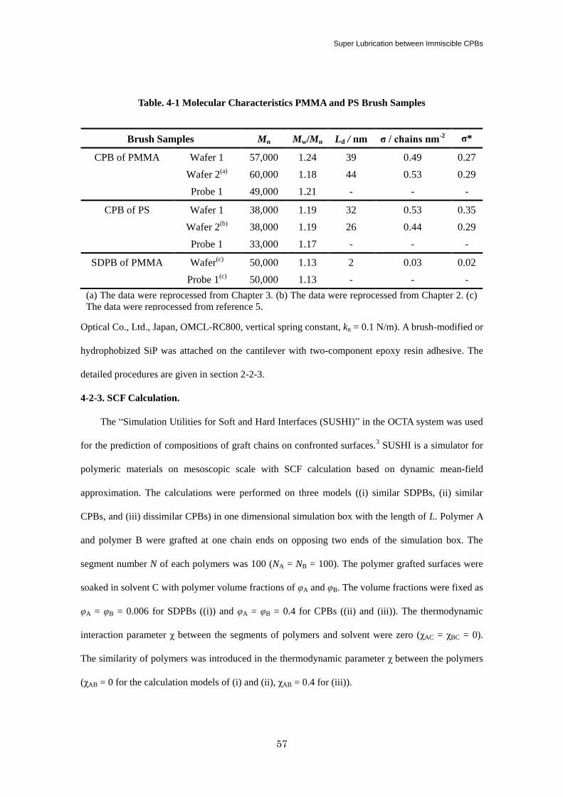
Super Lubrication between Immiscible CPBs
57
Optical Co., Ltd., Japan, OMCL-RC800, vertical spring constant, kn = 0.1 N/m). A brush-modified or
hydrophobized SiP was attached on the cantilever with two-component epoxy resin adhesive. The
detailed procedures are given in section 2-2-3.
4-2-3. SCF Calculation.
The “Simulation Utilities for Soft and Hard Interfaces (SUSHI)” in the OCTA system was used
for the prediction of compositions of graft chains on confronted surfaces.3 SUSHI is a simulator for
polymeric materials on mesoscopic scale with SCF calculation based on dynamic mean-field
approximation. The calculations were performed on three models ((i) similar SDPBs, (ii) similar
CPBs, and (iii) dissimilar CPBs) in one dimensional simulation box with the length of L. Polymer A
and polymer B were grafted at one chain ends on opposing two ends of the simulation box. The
segment number N of each polymers was 100 (NA = NB = 100). The polymer grafted surfaces were
soaked in solvent C with polymer volume fractions of φA and φB. The volume fractions were fixed as
φA = φB = 0.006 for SDPBs ((i)) and φA = φB = 0.4 for CPBs ((ii) and (iii)). The thermodynamic
interaction parameter χ between the segments of polymers and solvent were zero (χAC = χBC = 0).
The similarity of polymers was introduced in the thermodynamic parameter χ between the polymers
(χAB = 0 for the calculation models of (i) and (ii), χAB = 0.4 for (iii)).
Table. 4-1 Molecular Characteristics PMMA and PS Brush Samples
Brush Samples Mn Mw/Mn Ld / nm σ / chains nm-2
σ*
CPB of PMMA Wafer 1 57,000 1.24 39 0.49 0.27
Wafer 2(a) 60,000 1.18 44 0.53 0.29
Probe 1 49,000 1.21 - - -
CPB of PS Wafer 1 38,000 1.19 32 0.53 0.35
Wafer 2(b) 38,000 1.19 26 0.44 0.29
Probe 1 33,000 1.17 - - -
SDPB of PMMA Wafer(c) 50,000 1.13 2 0.03 0.02
Probe 1(c) 50,000 1.13 - - -
(a) The data were reprocessed from Chapter 3. (b) The data were reprocessed from Chapter 2. (c)
The data were reprocessed from reference 5.
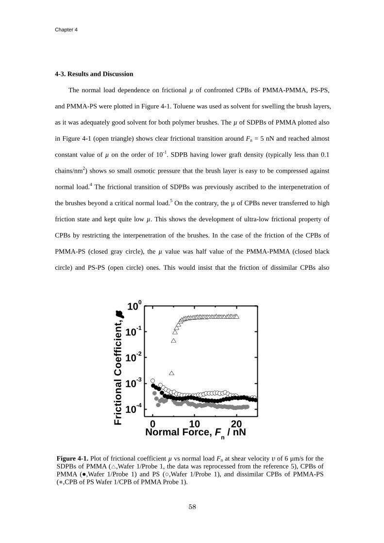
Chapter 4
58
4-3. Results and Discussion
The normal load dependence on frictional µ of confronted CPBs of PMMA-PMMA, PS-PS,
and PMMA-PS were plotted in Figure 4-1. Toluene was used as solvent for swelling the brush layers,
as it was adequately good solvent for both polymer brushes. The µ of SDPBs of PMMA plotted also
in Figure 4-1 (open triangle) shows clear frictional transition around Fn = 5 nN and reached almost
constant value of µ on the order of 10-1
. SDPB having lower graft density (typically less than 0.1
chains/nm2) shows so small osmotic pressure that the brush layer is easy to be compressed against
normal load.4 The frictional transition of SDPBs was previously ascribed to the interpenetration of
the brushes beyond a critical normal load.5 On the contrary, the µ of CPBs never transferred to high
friction state and kept quite low µ. This shows the development of ultra-low frictional property of
CPBs by restricting the interpenetration of the brushes. In the case of the friction of the CPBs of
PMMA-PS (closed gray circle), the µ value was half value of the PMMA-PMMA (closed black
circle) and PS-PS (open circle) ones. This would insist that the friction of dissimilar CPBs also
0 10 20
10-4
10-3
10-2
10-1
100
Fri
cti
on
al
Co
eff
icie
nt,
m
Normal Force, Fn / nN
Figure 4-1. Plot of frictional coefficient µ vs normal load Fn at shear velocity v of 6 µm/s for the
SDPBs of PMMA (△,Wafer 1/Probe 1, the data was reprocessed from the reference 5), CPBs of
PMMA (●,Wafer 1/Probe 1) and PS (○,Wafer 1/Probe 1), and dissimilar CPBs of PMMA-PS
(●,CPB of PS Wafer 1/CPB of PMMA Probe 1).
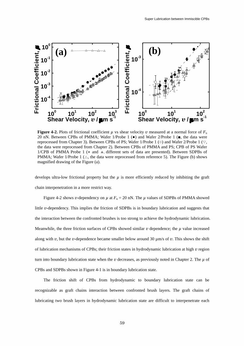
Super Lubrication between Immiscible CPBs
59
develops ultra-low frictional property but the µ is more efficiently reduced by inhibiting the graft
chain interpenetration in a more restrict way.
Figure 4-2 shows v-dependency on µ at Fn = 20 nN. The µ values of SDPBs of PMMA showed
little v-dependency. This implies the friction of SDPBs is in boundary lubrication and suggests that
the interaction between the confronted brushes is too strong to achieve the hydrodynamic lubrication.
Meanwhile, the three friction surfaces of CPBs showed similar v dependence; the µ value increased
along with v, but the v-dependence became smaller below around 30 µm/s of v. This shows the shift
of lubrication mechanisms of CPBs; their friction states in hydrodynamic lubrication at high v region
turn into boundary lubrication state when the v decreases, as previously noted in Chapter 2. The µ of
CPBs and SDPBs shown in Figure 4-1 is in boundary lubrication state.
The friction shift of CPBs from hydrodynamic to boundary lubrication state can be
recognizable as graft chains interaction between confronted brush layers. The graft chains of
lubricating two brush layers in hydrodynamic lubrication state are difficult to interpenetrate each
Figure 4-2. Plots of frictional coefficient µ vs shear velocity v measured at a normal force of Fn
20 nN. Between CPBs of PMMA; Wafer 1/Probe 1 (●) and Wafer 2/Probe 1 (■, the data were
reprocessed from Chapter 3). Between CPBs of PS; Wafer 1/Probe 1 (○) and Wafer 2/Probe 1 (▽,
the data were reprocessed from Chapter 2). Between CPBs of PMMA and PS; CPB of PS Wafer
1/CPB of PMMA Probe 1 (● and ▲, different sets of data are presented). Between SDPBs of
PMMA; Wafer 1/Probe 1 (△, the data were reprocessed from reference 5). The Figure (b) shows
magnified drawing of the Figure (a).
100
101
102
103
10-4
10-3
10-2
10-1
100
Fri
cti
on
al
Co
eff
icie
nt,
m
Shear Velocity, v / mm s-1
(a)
100
101
102
10-4
10-3
Fri
cti
on
al
Co
eff
icie
nt,
m
Shear Velocity, v / mm s-1
(b)
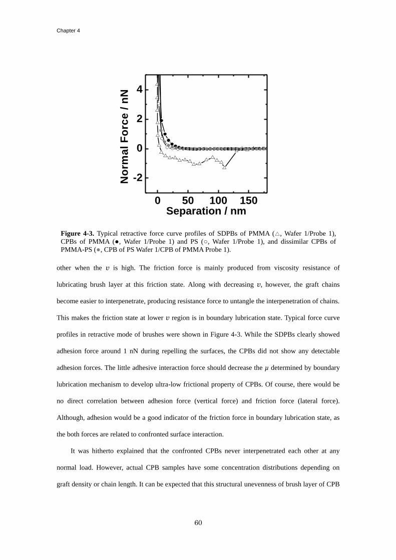
Chapter 4
60
other when the v is high. The friction force is mainly produced from viscosity resistance of
lubricating brush layer at this friction state. Along with decreasing v, however, the graft chains
become easier to interpenetrate, producing resistance force to untangle the interpenetration of chains.
This makes the friction state at lower v region is in boundary lubrication state. Typical force curve
profiles in retractive mode of brushes were shown in Figure 4-3. While the SDPBs clearly showed
adhesion force around 1 nN during repelling the surfaces, the CPBs did not show any detectable
adhesion forces. The little adhesive interaction force should decrease the µ determined by boundary
lubrication mechanism to develop ultra-low frictional property of CPBs. Of course, there would be
no direct correlation between adhesion force (vertical force) and friction force (lateral force).
Although, adhesion would be a good indicator of the friction force in boundary lubrication state, as
the both forces are related to confronted surface interaction.
It was hitherto explained that the confronted CPBs never interpenetrated each other at any
normal load. However, actual CPB samples have some concentration distributions depending on
graft density or chain length. It can be expected that this structural unevenness of brush layer of CPB
0 50 100 150
-2
0
2
4
No
rma
l F
orc
e /
nN
Separation / nm
Figure 4-3. Typical retractive force curve profiles of SDPBs of PMMA (△, Wafer 1/Probe 1),
CPBs of PMMA (●, Wafer 1/Probe 1) and PS (○, Wafer 1/Probe 1), and dissimilar CPBs of
PMMA-PS (●, CPB of PS Wafer 1/CPB of PMMA Probe 1).
Super Lubrication between Immiscible CPBs
61
allows a small portion of interpenetration at free ends of graft chains, which would determine the µ
in boundary lubrication state. The author simulated the graft chains composition distribution of
confronted two brush surfaces with SUSHI, simulation utilities of SCF calculation based on dynamic
mean-field approximation.3 In Figure 4-4, the volume fraction of graft polymers on two grafted
surfaces much close to each other were plotted against the separations. The schematic illustrations of
their graft chains on each surface were also depicted in Figure 4-4. The calculation model for SDPBs
(i) easily interpenetrated each other along with approaching the surfaces. It can be considered that
the interpenetration of SDPBs produced adhesive interaction force against repelling the surfaces (as
shown in Figure 4-3) and hence higher µ value on the order of 10-1
in boundary lubrication. On the
contrary, the interpenetration was gratefully suppressed in the case of CPBs model (ii), however,
suggesting that the graft chains of CPBs are somewhat contaminating at free ends surfaces. This
results from non-uniform concentration distribution of graft chains. The highly extended polymer
structures of CPB are somewhat disrupted to allow the small interpenetration. The actual samples of
CPBs have some certain distribution of graft chain length, which would certainly spread the
interpenetrate region of graft chains, though not to extent to the SDPBs case. Either way, it can be
considered that the small portion of interpenetration determines the µ of 10-4
order in boundary
lubrication state.
Introduction of thermodynamic interaction parameter (χ) between confronted polymer segments
is a way to reduce the small interpenetration of CPBs. When the parameter χAB = 0.4 was introduced
between segments of two graft polymer chains of CPBs, the interpenetration at free ends was
suppressed as shown in Figure 4-4 (iii). As it is known that phase separation of A-B block polymer is
occurred when the parameter of χABN is over 10.5,6 the parameter of χAB (NA + NB) = 80 of (iii)
would be enough to segregate the graft polymers of A and B. As PMMA and PS are immiscible
polymers each other, the calculation model of (iii) is attributed to the confronted CPBs of PMMA-PS
case. The CPBs of PMMA-PS showed lower µ value as half as that of the PS-PS and
PMMA-PMMA cases. Although these simulations do not give us quantitative evaluation of the
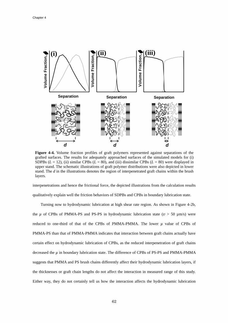
Chapter 4
62
interpenetrations and hence the frictional force, the depicted illustrations from the calculation results
qualitatively explain well the friction behaviors of SDPBs and CPBs in boundary lubrication state.
Turning now to hydrodynamic lubrication at high shear rate region. As shown in Figure 4-2b,
the µ of CPBs of PMMA-PS and PS-PS in hydrodynamic lubrication state (v > 50 µm/s) were
reduced to one-third of that of the CPBs of PMMA-PMMA. The lower µ value of CPBs of
PMMA-PS than that of PMMA-PMMA indicates that interaction between graft chains actually have
certain effect on hydrodynamic lubrication of CPBs, as the reduced interpenetration of graft chains
decreased the µ in boundary lubrication state. The difference of CPBs of PS-PS and PMMA-PMMA
suggests that PMMA and PS brush chains differently affect their hydrodynamic lubrication layers, if
the thicknesses or graft chain lengths do not affect the interaction in measured range of this study.
Either way, they do not certainly tell us how the interaction affects the hydrodynamic lubrication
Figure 4-4. Volume fraction profiles of graft polymers represented against separations of the
grafted surfaces. The results for adequately approached surfaces of the simulated models for (i)
SDPBs (L = 12), (ii) similar CPBs (L = 80), and (iii) dissimilar CPBs (L = 80) were displayed in
upper stand. The schematic illustrations of graft polymer distributions were also depicted in lower
stand. The d in the illustrations denotes the region of interpenetrated graft chains within the brush
layers.
d d d
(iii)(ii)
SeparationSeparation
Vo
lum
e F
rac
tio
n,
Vo
lum
e F
rac
tio
n,
Vo
lum
e F
rac
tio
n,
Separation
(i)
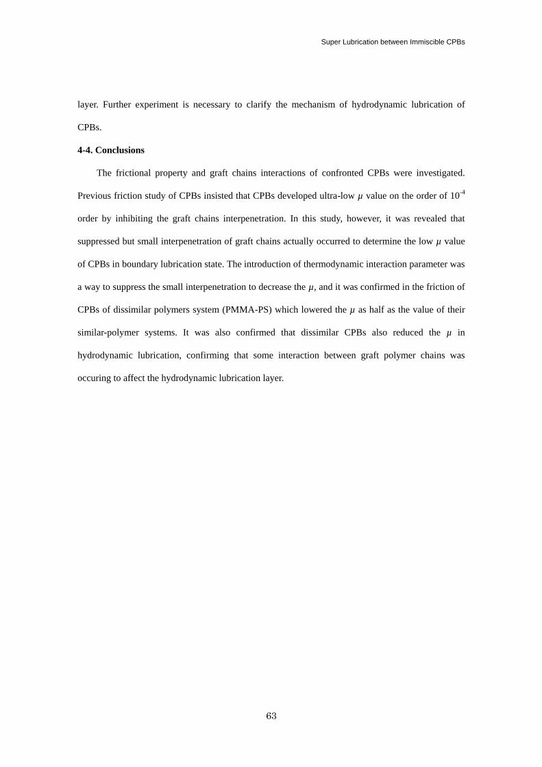
Super Lubrication between Immiscible CPBs
63
layer. Further experiment is necessary to clarify the mechanism of hydrodynamic lubrication of
CPBs.
4-4. Conclusions
The frictional property and graft chains interactions of confronted CPBs were investigated.
Previous friction study of CPBs insisted that CPBs developed ultra-low µ value on the order of 10-4
order by inhibiting the graft chains interpenetration. In this study, however, it was revealed that
suppressed but small interpenetration of graft chains actually occurred to determine the low µ value
of CPBs in boundary lubrication state. The introduction of thermodynamic interaction parameter was
a way to suppress the small interpenetration to decrease the µ, and it was confirmed in the friction of
CPBs of dissimilar polymers system (PMMA-PS) which lowered the µ as half as the value of their
similar-polymer systems. It was also confirmed that dissimilar CPBs also reduced the µ in
hydrodynamic lubrication, confirming that some interaction between graft polymer chains was
occuring to affect the hydrodynamic lubrication layer.
Chapter 4
64
References
(1) When polymers are obtained through ideal living polymerization process, the chain lengths of
each polymer chain obey poisson distribution. In that sense we can never obtain uniform
polymer through living polymerization process, although we can produce nearly monodisperse
polymer (Mw/Mn ~ 1). In addition, some termination reaction between two propagation radicals
is inevitable in living radical polymerization process, which somehow increases the breadth of
the distribution. The detailed mechanism of living radical polymerization can be referred to,
Matyjaszewski, K., Eds.; Controlled / Living Radical Polymerization: Progress in ATRP, NMP,
and RAFT (ACS Symposium Series); American Chemical Society: Washington, DC, 2000.
(2) Flory, P. J. Statistical Mechanics of Chain Molecules; John Wiley & Sons: New York, 1969.
(3) Honda, T.; Kodama, H.; Roan, J. R.; Morita, H.; Urashita, S.; Hasegawa, R.; Yokomizo, K.;
Kawakatsu, T.; Doi, M. SUSHI Users Manual; OCTA: Nagoya, 2004 (http://octa.jp).
(4) Tsujii, Y.; Ohno, K.; Yamamoto, S.; Goto, A.; Fukuda, T. Adv. Polym. Sci. 2006, 197, 1-45.
(5) Tsujii, Y.; Okayasu, K.; Nomura, A.; Ohno, K. Fukuda, T. Submitted to Macromolecules.
(6) (a) Leibler, L. Macromolecules 1980, 13, 1602-1617. (b) Matsen, M. W.; Bates, F. S.
Macromolecules 1996, 29, 1091-1098.
65
Chapter 5
Controlled Synthesis of Hydrophilic Concentrated Polymer Brushes and Their
Friction/Lubrication Properties in Aqueous Solutions
5-1. Introduction
In Chapter 2 ~ 4, the lubrication mechanism of the CPBs was discussed. These mechanistic
studies will allow for the design of friction/lubrication-controlled materials, which is one of the most
promising applications. Another potential application of polymer brushes has been directed toward
bio-interfaces with the intent of tuning the interactions between solid surfaces and biological
materials.1 Recently, the hydrophilic CPBs of poly (2-hydroxyethyl methacrylate) (PHEMA), poly
(2-hydroxyethyl acrylate) (PHEA) and poly (poly(ethylene glycol)methylether methacrylate)
(PPEGMA) were prepared via surface-initiated ATRP and revealed to extremely suppress
non-specific adsorption of proteins (for the PHEMA brush) and thereby cell adhesion2. Such
bio-inertness was ascribed to the entropically driven size-exclusion effect specific to the structure of
the CPB, providing a new potential for biomaterials. In addition to bio-inertness, good lubricity is
also required for some biomaterial applications. The PHEMA brush was, therefore, investigated on
its friction property, unfortunately giving less improvement than expected as mentioned above. This
may be due to insufficient hydrophilicity of PHEMA.3
The surface modification by polyelectrolytes is known to be effective in improving the mater
lubrication thanks to charged groups. Raviv et al. obtained a µ value on the order of 10-4
in water
between anionic-polyelectrolyte brushes prepared by the grafting-to method;4 electrostatic
interaction is responsible to such super lubrication, even though this brush can be regarded as a
SDPB from a relatively low graft density. Zwitterionic polymers including poly
(2-methacryloyloxyethyl phosphorylcholine) (PMPC) with good bio-compatibility5 were also
end-grafted to tune the surface properties. Kobayashi et al. succeeded in densely grafting such
Chapter 5
66
polymers via surface-initiated ATRP6 and reported frictional property (µ ~ 10
-1) and wear resistance
better than the corresponding spin-coated film by a so-called tribometer with a stainless steel or glass
probe.7 More recently, Chen et al. reported super lubrication in water between the brushes of
zwitterionic polymers (whose graft density was not reported) and ascribed it to the effective
formation of hydration sheet.8
To the best of our knowledge, it was still challenge to demonstrate super lubrication in water by
the concentrated-brush effects and clarify the mechanism of such water lubrication between the
CPBs of hydrophilic polymers. Among them, hydrophilic and neutral polymers with PEG side
chains exhibit hydration force and bio-compatibility depending on the number or the terminal
structure of PEG units,9 which may also influence the frictional property. Thus, the CPBs of such
PEG-containing polymers would enable the author to make a systematic study on the friction and
biocompatibility in aqueous systems. An electrically neutral chain would be preferred in this study
because electrostatic interaction should be less important, manifesting the potential
concentrated-brush effects in an aqueous system. Additionally, their properties are expected to serve
even under a high salt-concentration condition, e.g., our body fluid containing about 1 wt% salt
electrolytes.
In this study, the author newly synthesized the CPBs of water-soluble polymers, poly
(2-hydroxyethyl acrylate) (PHEA) (PEG-unit number, n = 1) and poly
(poly(oxyethyleneglycol)methylether acrylate) (PPEGA) (n = 8.5) via photo-induced
organotellurium-mediated radical polymerization (TERP). TERP is known to have high tolerance to
functional groups, better controllability and applicability for acrylates.10
For such brush samples, the
author studied the frictional property in water media using an colloidal-probe technique on an AFM.
The lubrication mechanism of these brushes is discussed in the view point of boundary and
hydrodynamic lubrication described in Chapter 2 ~ 4.
Synthesis of Hydrophilic CPBs and Their Friction/Lubrication
67
5-2. Experiment
5-2-1. Materials
2-Hydroxyethyl acrylate (HEA) (99%, Wako) was purified according to the literature.11
Poly
(ethyleneglycol)methylether acrylate (PEGA) (Aldrich, Mn ~ 454) was passed through a column of
basic alumina to remove inhibitors before use. Tellurium compounds, ethyl
2-methyl-2-(methyltellanyl)propanoate (EMA-TeMe) and dimethylditelluride ((TeMe)2), were
prepared according to the method previously reported by Yamago et al.10(b)
All other reagents
including 2-iodo-2-methylpropanenitrile (CP-I, 99 %, Tokyo Chemical Industry Co., Ltd., Japan)
were used as received.
A silicon wafer (Ferrotec Corp., Japan, one side chemical/mechanical polished, 525 mm
thickness) was cleaned by ultrasonication in CHCl3 for 15min and ultraviolet (UV) / ozone treatment
for 10min just before fixation of an initiator. A silica particle (SiP, HIPRECICA SP, radius R of 5
µm) was received from Ube Nitto Kasei Co., Ltd., and was used as a probe of AFM.
5-2-2. Synthesis of IHE
As a fixable initiator for photo-induced TERP, an iodine-type surface initiator,
(2-iodo-2-methyl)propionyloxyhexyl triethoxysilane (IHE), was newly synthesized by the
halogen-exchange reaction from (2-bromo-2-methyl)propionyloxyhexyl triethoxysilane (BHE,
synthesized according to the literature12
). BHE (4 g, 9.7 mmol) was added dropwise to a solution of
sodium iodine (7.3 g, 48 mmol) in dry acetone (70 ml) and magnetically stirred for 5 days at 50 ºC.
The reactant was evaporated to dryness under reduced pressure. The residue was diluted with dry
CHCl3 (300 ml) and passed through a filter paper. The evaporation of CHCl3 from the filtrate gave
IHE as a brown oil (2.5 g, 56 % yield); 1H NMR (CDCl3): δ 0.64 (t, 2H, SiCH2), 1.23 (t, 9H,
CH3CH2OSi), 1.32-1.54 and 1.60-1.75 (br, 8H, CH2), 2.08 (s, 6H, CCH3), 3.81 (q, 6H, CH3CH2OSi),
4.15 (t, 2H, CH2O). Anal. Calcd for C16H33IO5Si: C, 41.74; H, 7.22; I, 27.56. Found: C, 41.05; H,
7.01; I, 27.62.
5-2-3. Synthesis of Concentrated PHEA and PPEGA Brushes via Photo-induced TERP
Chapter 5
68
A silicon wafer was immersed in an ethanol solution of IHE (1 wt%) and 28%-aqueous NH3 (5
wt%) for 12 h at room temperature in dark condition to immobilize the initiating groups and then
washed with ethanol. For the synthesis of PHEA brushes, the IHE-immobilized wafer was immersed
in a degassed HEA (in bulk) containing (TeMe)2 (0.3 mM) and a free initiator (0.1 mM), CP-I or
EMA-TeMe, sealed under argon atmosphere in a flat grass cell (3 mm thick) and irradiated with
visible light (450~530 nm) at 80 ºC for a prescribed time. Irradiation was made with a 300 W
xenon-light source (MAX-302, Asahi Spectra Co., Ltd.) through a bandpass filter of the desired
wavelength. After polymerization, the solution was diluted with N,N-dimethylformamide (DMF) to a
known concentration and analyzed by gel permeation chromatography (GPC) to determine the
molecular weights and conversion. The substrate was copiously rinsed with methanol to remove
physisorbed free polymers and impurities. For the synthesis of PPEGA brushes, the
IHE-immobilized substrate was immersed in a degassed DMF solution of PEGA (1 M), (TeMe)2 (0.1
mM) and EMA-TeMe (0.2 mM) and treated in the same way as above described. SiPs were also
modified with PHEA and PPEGA brushes by the same procedure, in which the concentration of SiPs
was kept 0.5 wt% for all steps.
5-2-4. AFM Measurement for Swelling and Frictional Property of PHEA and PPEGA Brushes
An atomic force microscope (Seiko Instruments Inc., Japan, SPI400) was used to evaluate the
microscopic surface character of the PHEA and PPEGA brush surfaces. For the measurement of
equilibrium swollen thickness, a bare (unmodified) SiP was attached on a V-shaped cantilever
(Olympus Optical Co., Ltd., Japan, vertical spring constant kn = 0.15 N/m) with two-component
epoxy resin adhesive and used as a probe. For the measurement of friction force and adhesive force
between the brush surfaces, the above-mentioned brush-modified SiP was attached on a
rectangular-shaped cantilever (Olympus Optical Co., Ltd, kn = 0.1 N/m, lateral spring constant ks =
23 N/m). The detailed procedures were described in section 2-2-3.
5-2-5. Other Measurements
The GPC analysis was made on a Shodex GPC 101-series high-speed liquid chromatograph
Synthesis of Hydrophilic CPBs and Their Friction/Lubrication
69
(Tokyo) equipped with a differential refractometer (Shodex RI-101). DMF solution of 10 mM LiBr
was used as eluent with a flow rate of 0.8 mL/min at 40 ºC. Two Shodex gel columns LF804
(300mm length × 8.0 mm inner diameter; bead size = 6 µm) were used and calibrated with standard
poly (methyl methacrylate)s (PMMAs). Sample detection was also made with a multiangle laser
light-scattering (MALLS) detector, a Wyatt Technology DAWN HELEOS (Santa Barbara, CA),
equipped with a Ga-As laser (λ = 658 nm) The refractive-index increments dn/dc were determined to
be 0.061 and 0.045 mL·g-1
for PHEA and PPEGA, respectively, by a Wyatt Technology Optilab rEX
differential refractometer (λ = 658 nm).
The thickness of the brush layer in a dry state was determined by a compensator-rotating,
spectroscopic ellipsometer (M-2000UTM
, J. A. Woolam, NE, USA) equipped with a D2 and QTH
lamps. The polarizer angle was 45º, and the incident angle was 70º. For analyzing thus obtained
ellipsometric data, the optical constants were determined for the spincast film with a thickness of ca.
200 nm for each polymer.
5-3. Result and discussion
5-3-1. Graft Polymerization of HEA and PEGA by Photo-induced TERP Technique
The LRP of HEA was firstly reported via ATRP.13
Recently, better control of molecular weight
and molecular weight distribution of PHEMA was achieved by photo-induced TERP.15
The TERP
technique developed by Yamago et al. is one of novel LPRs equipped with good tolerance to
functional groups and easy transformation of end groups. The key process, i.e., the reversible
activation of dormant species to propagating radical, of TERP includes the degenerative (exchange)
chain transfer (Scheme 5-1b) as well as the homolytic dissociation of a C-Te bound (Scheme 5-1a).
Under usual conditions, the thermal dissociation insufficient occurs so that a conversional radical
initiator is needed for control of polymerization. Yamago et al. succeeded in photochemically
enhancing such homolytic dissociation and hence in better controlling the polymerization without
radical initiator.13
However, it still remained a challenge to synthesize low-polydispersity PHEA of
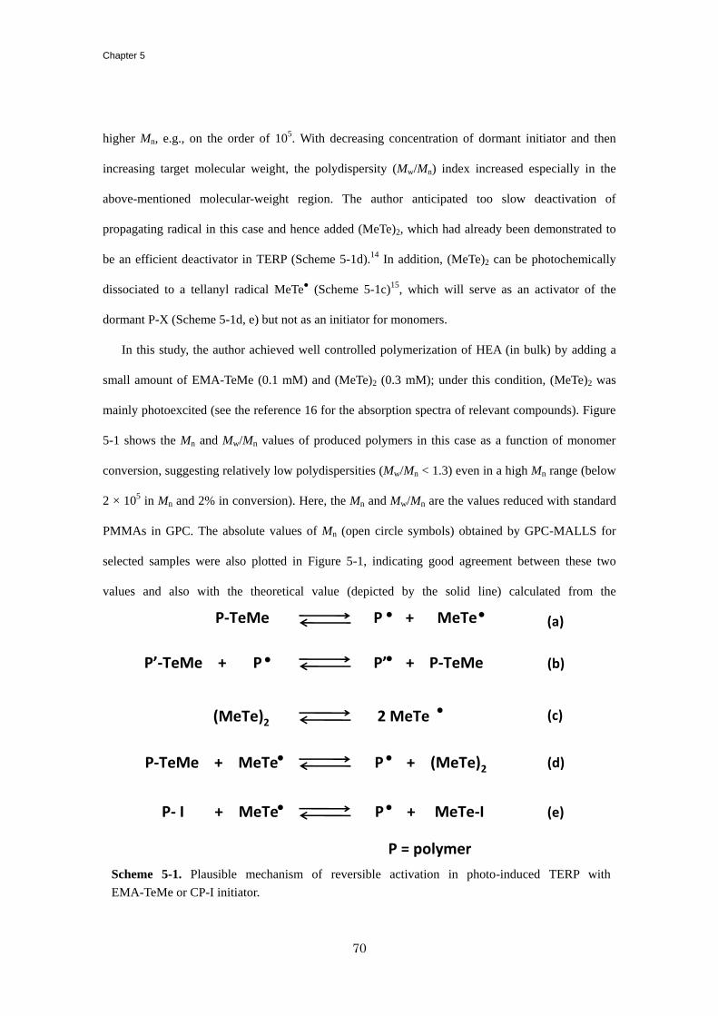
Chapter 5
70
higher Mn, e.g., on the order of 105. With decreasing concentration of dormant initiator and then
increasing target molecular weight, the polydispersity (Mw/Mn) index increased especially in the
above-mentioned molecular-weight region. The author anticipated too slow deactivation of
propagating radical in this case and hence added (MeTe)2, which had already been demonstrated to
be an efficient deactivator in TERP (Scheme 5-1d).14
In addition, (MeTe)2 can be photochemically
dissociated to a tellanyl radical MeTe● (Scheme 5-1c)
15, which will serve as an activator of the
dormant P-X (Scheme 5-1d, e) but not as an initiator for monomers.
In this study, the author achieved well controlled polymerization of HEA (in bulk) by adding a
small amount of EMA-TeMe (0.1 mM) and (MeTe)2 (0.3 mM); under this condition, (MeTe)2 was
mainly photoexcited (see the reference 16 for the absorption spectra of relevant compounds). Figure
5-1 shows the Mn and Mw/Mn values of produced polymers in this case as a function of monomer
conversion, suggesting relatively low polydispersities (Mw/Mn < 1.3) even in a high Mn range (below
2 × 10⁵ in Mn and 2% in conversion). Here, the Mn and Mw/Mn are the values reduced with standard
PMMAs in GPC. The absolute values of Mn (open circle symbols) obtained by GPC-MALLS for
selected samples were also plotted in Figure 5-1, indicating good agreement between these two
values and also with the theoretical value (depicted by the solid line) calculated from the
Scheme 5-1. Plausible mechanism of reversible activation in photo-induced TERP with
EMA-TeMe or CP-I initiator.
P = polymer
(MeTe)2 2 MeTe
P- I + MeTe P + MeTe-I
(c)
(d)
P’-TeMe + P P’ + P-TeMe
P-TeMe P + MeTe (a)
(b)
P-TeMe + MeTe P + (MeTe)2
(e)
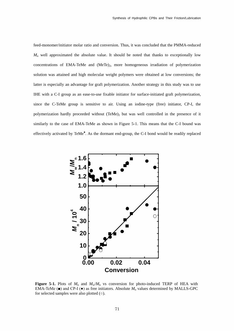
Synthesis of Hydrophilic CPBs and Their Friction/Lubrication
71
feed-monomer/initiator molar ratio and conversion. Thus, it was concluded that the PMMA-reduced
Mn well approximated the absolute value. It should be noted that thanks to exceptionally low
concentrations of EMA-TeMe and (MeTe)2, more homogeneous irradiation of polymerization
solution was attained and high molecular weight polymers were obtained at low conversions; the
latter is especially an advantage for graft polymerization. Another strategy in this study was to use
IHE with a C-I group as an ease-to-use fixable initiator for surface-initiated graft polymerization,
since the C-TeMe group is sensitive to air. Using an iodine-type (free) initiator, CP-I, the
polymerization hardly proceeded without (TeMe)2 but was well controlled in the presence of it
similarly to the case of EMA-TeMe as shown in Figure 5-1. This means that the C-I bound was
effectively activated by TeMe●. As the dormant end-group, the C-I bond would be readily replaced
1.0
1.2
1.4
1.6
0.00 0.02 0.040
10
20
30
40
50
Mw/M
n
Mn /
10
4
Conversion
Figure 5-1. Plots of Mn and Mw/Mn vs conversion for photo-induced TERP of HEA with
EMA-TeMe (■) and CP-I (●) as free initiators. Absolute Mn values determined by MALLS-GPC
for selected samples were also plotted (○).
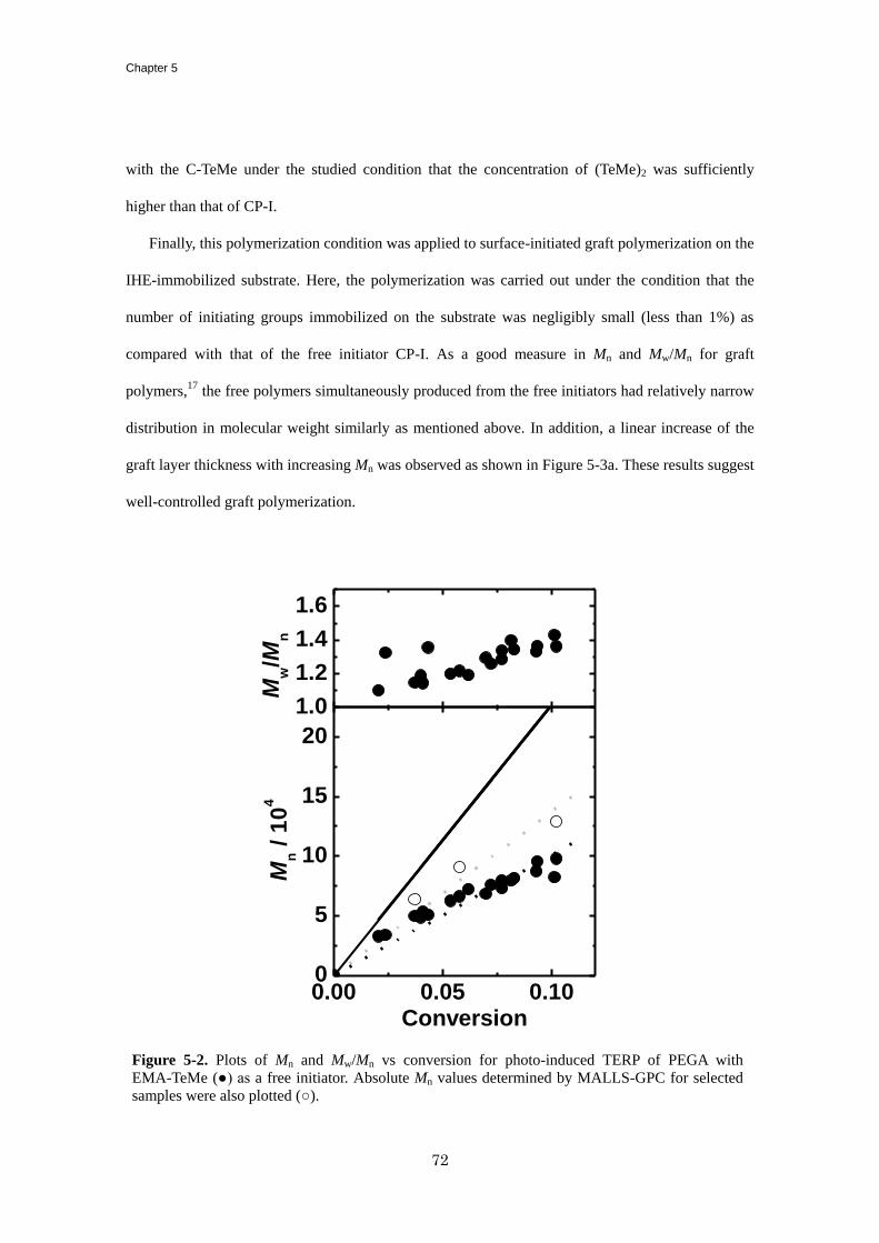
Chapter 5
72
with the C-TeMe under the studied condition that the concentration of (TeMe)2 was sufficiently
higher than that of CP-I.
Finally, this polymerization condition was applied to surface-initiated graft polymerization on the
IHE-immobilized substrate. Here, the polymerization was carried out under the condition that the
number of initiating groups immobilized on the substrate was negligibly small (less than 1%) as
compared with that of the free initiator CP-I. As a good measure in Mn and Mw/Mn for graft
polymers,17
the free polymers simultaneously produced from the free initiators had relatively narrow
distribution in molecular weight similarly as mentioned above. In addition, a linear increase of the
graft layer thickness with increasing Mn was observed as shown in Figure 5-3a. These results suggest
well-controlled graft polymerization.
1.0
1.2
1.4
1.6
Mw/M
n
0.00 0.05 0.100
5
10
15
20
Mn /
10
4
Conversion
Figure 5-2. Plots of Mn and Mw/Mn vs conversion for photo-induced TERP of PEGA with
EMA-TeMe (●) as a free initiator. Absolute Mn values determined by MALLS-GPC for selected
samples were also plotted (○).
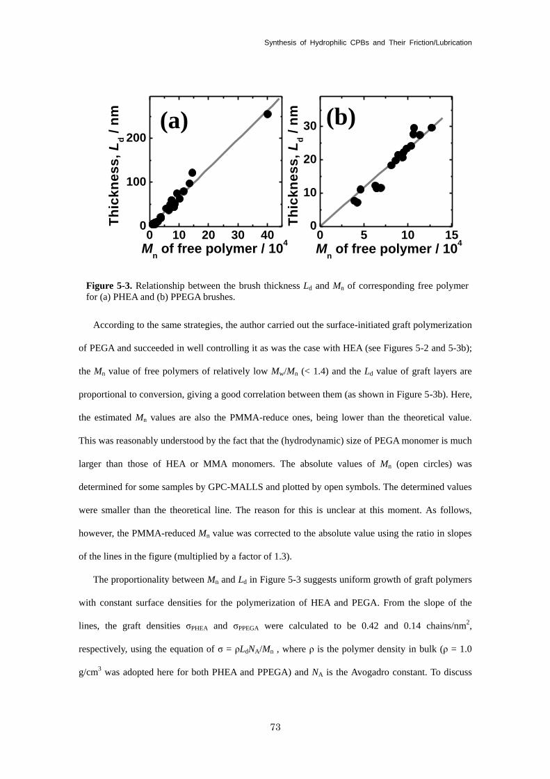
Synthesis of Hydrophilic CPBs and Their Friction/Lubrication
73
According to the same strategies, the author carried out the surface-initiated graft polymerization
of PEGA and succeeded in well controlling it as was the case with HEA (see Figures 5-2 and 5-3b);
the Mn value of free polymers of relatively low Mw/Mn (< 1.4) and the Ld value of graft layers are
proportional to conversion, giving a good correlation between them (as shown in Figure 5-3b). Here,
the estimated Mn values are also the PMMA-reduce ones, being lower than the theoretical value.
This was reasonably understood by the fact that the (hydrodynamic) size of PEGA monomer is much
larger than those of HEA or MMA monomers. The absolute values of Mn (open circles) was
determined for some samples by GPC-MALLS and plotted by open symbols. The determined values
were smaller than the theoretical line. The reason for this is unclear at this moment. As follows,
however, the PMMA-reduced Mn value was corrected to the absolute value using the ratio in slopes
of the lines in the figure (multiplied by a factor of 1.3).
The proportionality between Mn and Ld in Figure 5-3 suggests uniform growth of graft polymers
with constant surface densities for the polymerization of HEA and PEGA. From the slope of the
lines, the graft densities σPHEA and σPPEGA were calculated to be 0.42 and 0.14 chains/nm2,
respectively, using the equation of σ = ρLdNA/Mn , where ρ is the polymer density in bulk (ρ = 1.0
g/cm3 was adopted here for both PHEA and PPEGA) and NA is the Avogadro constant. To discuss
0 10 20 30 400
100
200
(b)
Th
ick
ne
ss
, L
d /
nm
Mn of free polymer / 10
4
Th
ick
ne
ss
, L
d /
nm
Mn of free polymer / 10
4
(a)
0 5 10 150
10
20
30
Figure 5-3. Relationship between the brush thickness Ld and Mn of corresponding free polymer
for (a) PHEA and (b) PPEGA brushes.
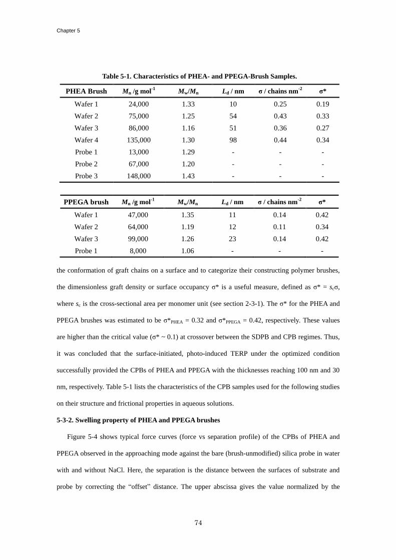
Chapter 5
74
the conformation of graft chains on a surface and to categorize their constructing polymer brushes,
the dimensionless graft density or surface occupancy σ* is a useful measure, defined as σ* = scσ,
where sc is the cross-sectional area per monomer unit (see section 2-3-1). The σ* for the PHEA and
PPEGA brushes was estimated to be σ*PHEA = 0.32 and σ*PPEGA = 0.42, respectively. These values
are higher than the critical value (σ* ~ 0.1) at crossover between the SDPB and CPB regimes. Thus,
it was concluded that the surface-initiated, photo-induced TERP under the optimized condition
successfully provided the CPBs of PHEA and PPEGA with the thicknesses reaching 100 nm and 30
nm, respectively. Table 5-1 lists the characteristics of the CPB samples used for the following studies
on their structure and frictional properties in aqueous solutions.
5-3-2. Swelling property of PHEA and PPEGA brushes
Figure 5-4 shows typical force curves (force vs separation profile) of the CPBs of PHEA and
PPEGA observed in the approaching mode against the bare (brush-unmodified) silica probe in water
with and without NaCl. Here, the separation is the distance between the surfaces of substrate and
probe by correcting the “offset” distance. The upper abscissa gives the value normalized by the
Table 5-1. Characteristics of PHEA- and PPEGA-Brush Samples.
PHEA Brush Mn /g mol-1
Mw/Mn Ld / nm σ / chains nm-2
σ*
Wafer 1 24,000 1.33 10 0.25 0.19
Wafer 2 75,000 1.25 54 0.43 0.33
Wafer 3 86,000 1.16 51 0.36 0.27
Wafer 4 135,000 1.30 98 0.44 0.34
Probe 1 13,000 1.29 - - -
Probe 2 67,000 1.20 - - -
Probe 3 148,000 1.43 - - -
PPEGA brush Mn /g mol-1
Mw/Mn Ld / nm σ / chains nm-2
σ*
Wafer 1 47,000 1.35 11 0.14 0.42
Wafer 2 64,000 1.19 12 0.11 0.34
Wafer 3 99,000 1.26 23 0.14 0.42
Probe 1 8,000 1.06 - - -
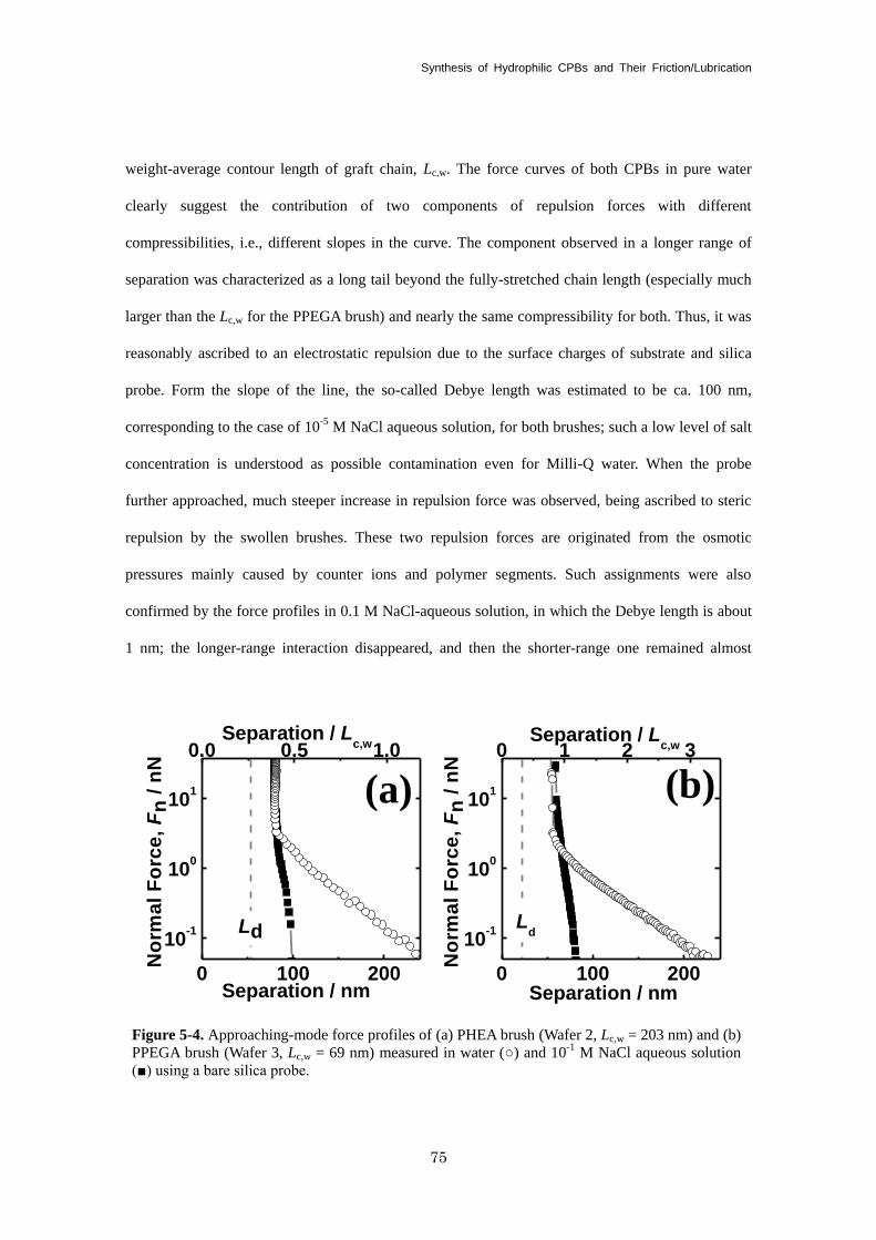
Synthesis of Hydrophilic CPBs and Their Friction/Lubrication
75
weight-average contour length of graft chain, Lc,w. The force curves of both CPBs in pure water
clearly suggest the contribution of two components of repulsion forces with different
compressibilities, i.e., different slopes in the curve. The component observed in a longer range of
separation was characterized as a long tail beyond the fully-stretched chain length (especially much
larger than the Lc,w for the PPEGA brush) and nearly the same compressibility for both. Thus, it was
reasonably ascribed to an electrostatic repulsion due to the surface charges of substrate and silica
probe. Form the slope of the line, the so-called Debye length was estimated to be ca. 100 nm,
corresponding to the case of 10-5
M NaCl aqueous solution, for both brushes; such a low level of salt
concentration is understood as possible contamination even for Milli-Q water. When the probe
further approached, much steeper increase in repulsion force was observed, being ascribed to steric
repulsion by the swollen brushes. These two repulsion forces are originated from the osmotic
pressures mainly caused by counter ions and polymer segments. Such assignments were also
confirmed by the force profiles in 0.1 M NaCl-aqueous solution, in which the Debye length is about
1 nm; the longer-range interaction disappeared, and then the shorter-range one remained almost
Figure 5-4. Approaching-mode force profiles of (a) PHEA brush (Wafer 2, Lc,w = 203 nm) and (b)
PPEGA brush (Wafer 3, Lc,w = 69 nm) measured in water (○) and 10-1
M NaCl aqueous solution
(■) using a bare silica probe.
0 100 200
10-1
100
101
No
rma
l F
orc
e,
Fn
/ n
N
Separation / nm
(a)
Ld
0 100 200
10-1
100
101
No
rma
l F
orc
e,
Fn
/ n
N
Separation / nm
(b)
Ld
0.0 0.5 1.0 Separation / L
c,w 0 1 2 3 Separation / L
c,w
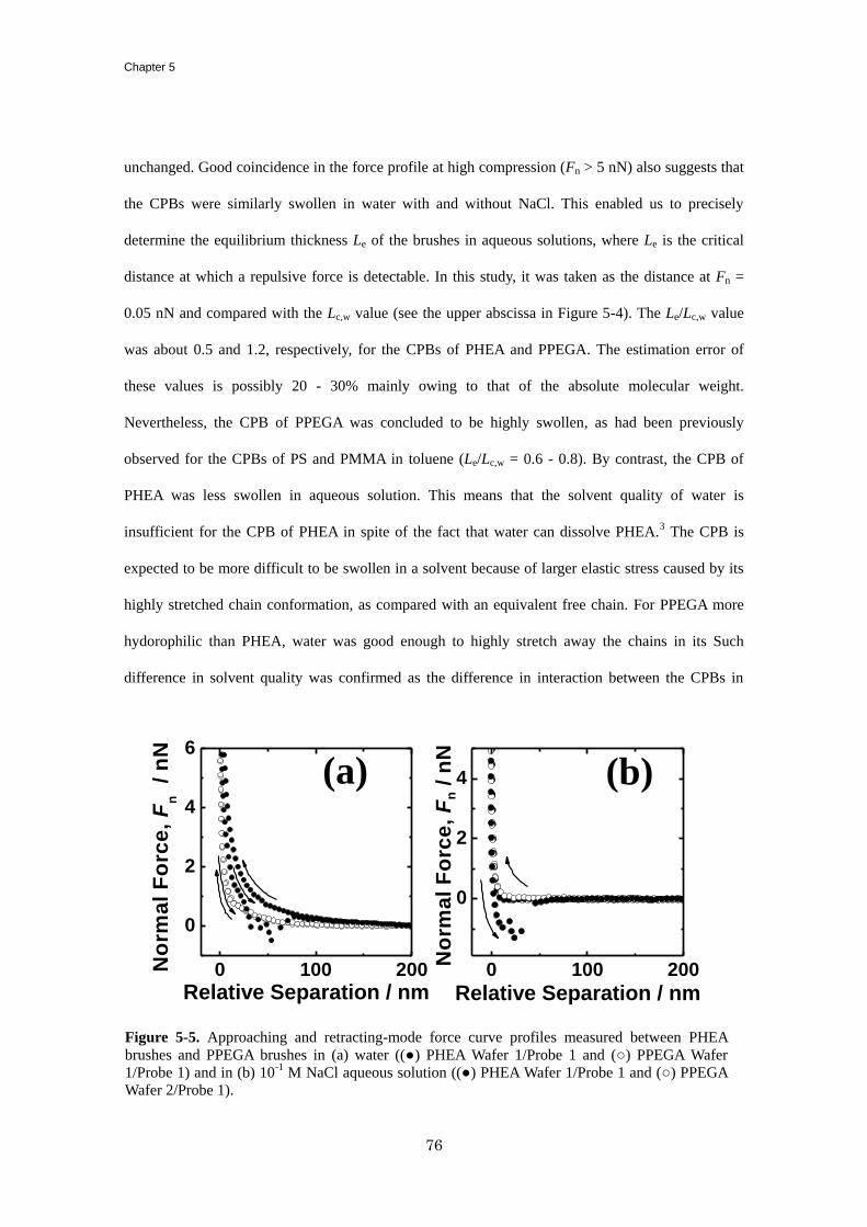
Chapter 5
76
unchanged. Good coincidence in the force profile at high compression (Fn > 5 nN) also suggests that
the CPBs were similarly swollen in water with and without NaCl. This enabled us to precisely
determine the equilibrium thickness Le of the brushes in aqueous solutions, where Le is the critical
distance at which a repulsive force is detectable. In this study, it was taken as the distance at Fn =
0.05 nN and compared with the Lc,w value (see the upper abscissa in Figure 5-4). The Le/Lc,w value
was about 0.5 and 1.2, respectively, for the CPBs of PHEA and PPEGA. The estimation error of
these values is possibly 20 - 30% mainly owing to that of the absolute molecular weight.
Nevertheless, the CPB of PPEGA was concluded to be highly swollen, as had been previously
observed for the CPBs of PS and PMMA in toluene (Le/Lc,w = 0.6 - 0.8). By contrast, the CPB of
PHEA was less swollen in aqueous solution. This means that the solvent quality of water is
insufficient for the CPB of PHEA in spite of the fact that water can dissolve PHEA.3 The CPB is
expected to be more difficult to be swollen in a solvent because of larger elastic stress caused by its
highly stretched chain conformation, as compared with an equivalent free chain. For PPEGA more
hydorophilic than PHEA, water was good enough to highly stretch away the chains in its Such
difference in solvent quality was confirmed as the difference in interaction between the CPBs in
Figure 5-5. Approaching and retracting-mode force curve profiles measured between PHEA
brushes and PPEGA brushes in (a) water ((●) PHEA Wafer 1/Probe 1 and (○) PPEGA Wafer
1/Probe 1) and in (b) 10-1
M NaCl aqueous solution ((●) PHEA Wafer 1/Probe 1 and (○) PPEGA
Wafer 2/Probe 1).
0 100 200
0
2
4
6
(b)
No
rma
l F
orc
e,
Fn
/ n
N
Relative Separation / nm
(a)
0 100 200
0
2
4
No
rma
l F
orc
e,
Fn /
nN
Relative Separation / nm
Synthesis of Hydrophilic CPBs and Their Friction/Lubrication
77
aqueous solutions. Figure 5-5 shows typical force profiles measured in the approaching and
retracting modes between the confronted CPBs (using the brush-modified probe) in (a) pure water
and (b) 0.1 M NaCl aqueous solution; the abscissa in this figure is relative separation, since the
“off-set” distance was not determined using the brush-modified probe. The above-mentioned,
long-ranged repulsion force owing to the electrostatic interaction was also seen between the CPBs
only in pure water. More importantly, an adhesive interaction was clearly observed in each aqueous
solution between the CPBs of PHEA but not between the CPBs of PPEGA. This indicates the
attractive interaction between the PHEA segments in water and hence insufficient solvent quality of
water for PHEA. The observed adhesion force was estimated to be about 1.5 nN in average both in
pure water and in salt-aqueous solution. This strongly affected the frictional property between the
CPBs, as will be discussed.
5-3-3. Frictional property of PHEA and PPEGAA brush
Figure 5-6 shows the Fn-dependence of µ for the concentrated brushes of PHEA and PPEGA
measured at v = 7 µm/s in pure water and 0.1 M NaCl aqueous solution. Since an adhesion force acts
as an additional normal load as previously indicated (section 2-2-2), the µ value was corrected by
adhesion force Fa as µ = Fs / (Fn + Fa) and plotted in the figure, suggesting that such correction had
little effect on the following discussion. At low loads, the µ increased with Fn in any case, and for
each brush system, the value in water was significantly smaller than that in the presence of 0.1 M
NaCl. These presumably suggest that the lubricating layer of solvent was constructed between the
confronted CPBs and that the electrostatically repulsive interaction was contributed to stabilize it,
but that such layer was easily destroyed by applying normal force even in water. The contribution of
electrostatic interaction was limited only at low loads, since it was not originated from the brush
component but possibly from a small amount of charges remaining on the silica-substrate surfaces.
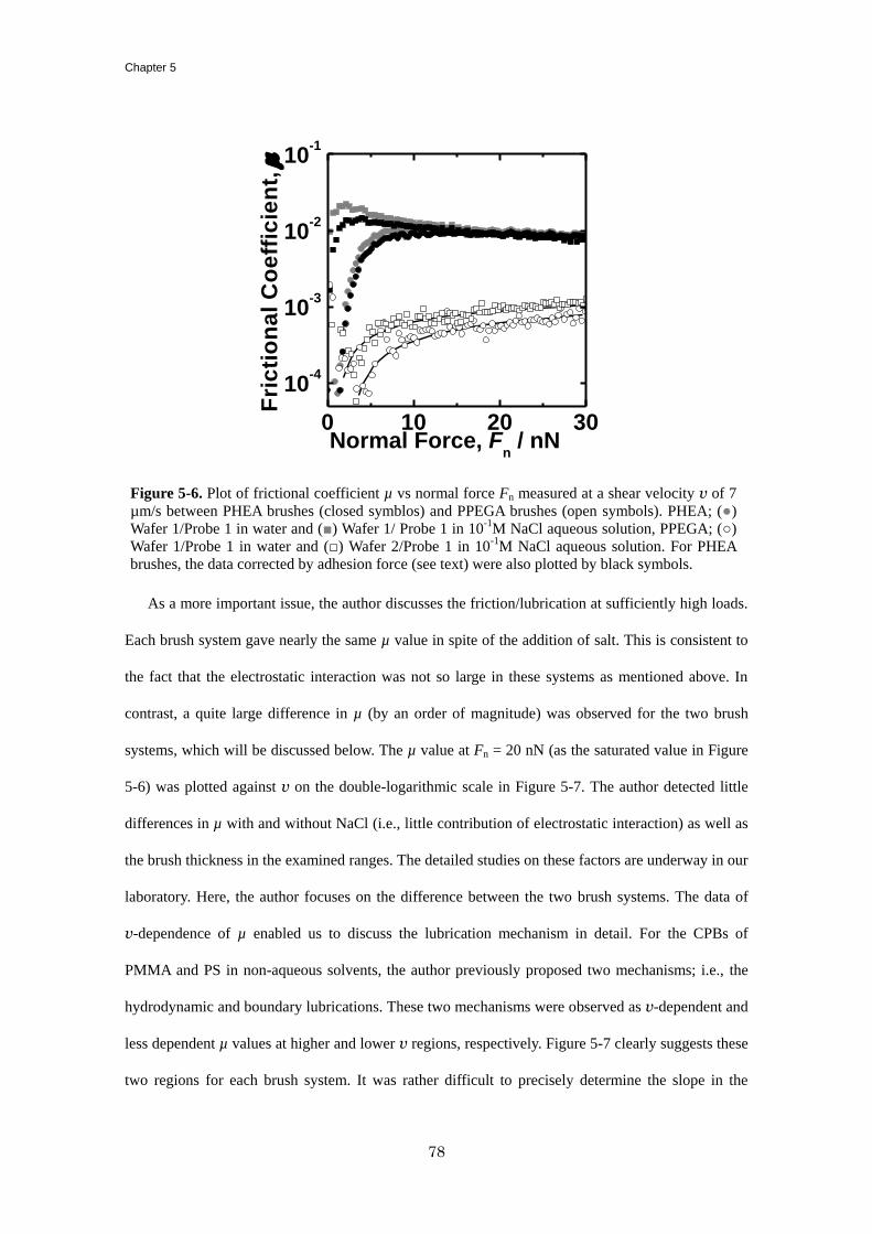
Chapter 5
78
As a more important issue, the author discusses the friction/lubrication at sufficiently high loads.
Each brush system gave nearly the same µ value in spite of the addition of salt. This is consistent to
the fact that the electrostatic interaction was not so large in these systems as mentioned above. In
contrast, a quite large difference in µ (by an order of magnitude) was observed for the two brush
systems, which will be discussed below. The µ value at Fn = 20 nN (as the saturated value in Figure
5-6) was plotted against v on the double-logarithmic scale in Figure 5-7. The author detected little
differences in µ with and without NaCl (i.e., little contribution of electrostatic interaction) as well as
the brush thickness in the examined ranges. The detailed studies on these factors are underway in our
laboratory. Here, the author focuses on the difference between the two brush systems. The data of
v-dependence of µ enabled us to discuss the lubrication mechanism in detail. For the CPBs of
PMMA and PS in non-aqueous solvents, the author previously proposed two mechanisms; i.e., the
hydrodynamic and boundary lubrications. These two mechanisms were observed as v-dependent and
less dependent µ values at higher and lower v regions, respectively. Figure 5-7 clearly suggests these
two regions for each brush system. It was rather difficult to precisely determine the slope in the
0 10 20 30
10-4
10-3
10-2
10-1
Fri
cti
on
al
Co
eff
icie
nt,
m
Normal Force, Fn / nN
Figure 5-6. Plot of frictional coefficient µ vs normal force Fn measured at a shear velocity v of 7
µm/s between PHEA brushes (closed symblos) and PPEGA brushes (open symbols). PHEA; (●)
Wafer 1/Probe 1 in water and (■) Wafer 1/ Probe 1 in 10-1
M NaCl aqueous solution, PPEGA; (○)
Wafer 1/Probe 1 in water and (□) Wafer 2/Probe 1 in 10-1
M NaCl aqueous solution. For PHEA
brushes, the data corrected by adhesion force (see text) were also plotted by black symbols.
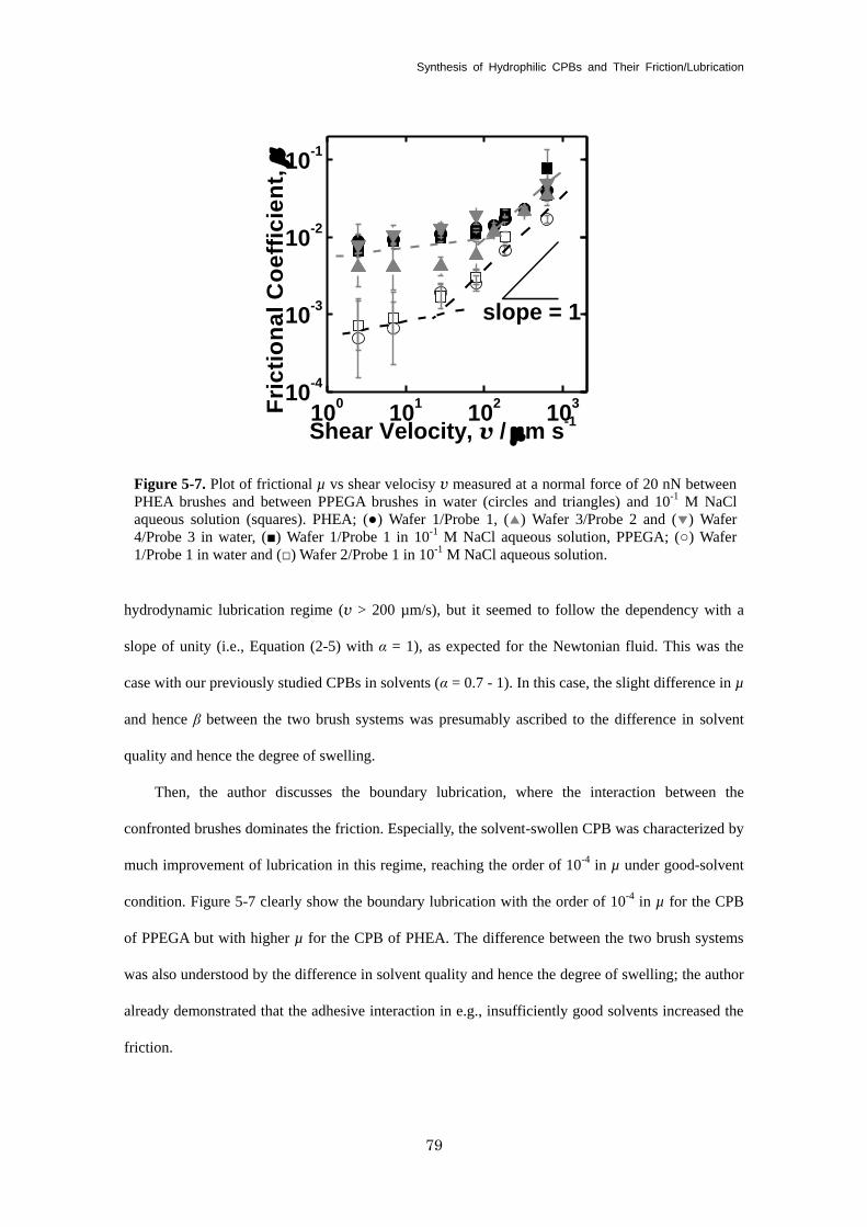
Synthesis of Hydrophilic CPBs and Their Friction/Lubrication
79
hydrodynamic lubrication regime (v > 200 µm/s), but it seemed to follow the dependency with a
slope of unity (i.e., Equation (2-5) with α = 1), as expected for the Newtonian fluid. This was the
case with our previously studied CPBs in solvents (α = 0.7 - 1). In this case, the slight difference in µ
and hence β between the two brush systems was presumably ascribed to the difference in solvent
quality and hence the degree of swelling.
Then, the author discusses the boundary lubrication, where the interaction between the
confronted brushes dominates the friction. Especially, the solvent-swollen CPB was characterized by
much improvement of lubrication in this regime, reaching the order of 10-4
in µ under good-solvent
condition. Figure 5-7 clearly show the boundary lubrication with the order of 10-4
in µ for the CPB
of PPEGA but with higher µ for the CPB of PHEA. The difference between the two brush systems
was also understood by the difference in solvent quality and hence the degree of swelling; the author
already demonstrated that the adhesive interaction in e.g., insufficiently good solvents increased the
friction.
100
101
102
103
10-4
10-3
10-2
10-1
Fri
cti
on
al
Co
eff
icie
nt,
m
Shear Velocity, v / mm s-1
slope = 1
Figure 5-7. Plot of frictional µ vs shear velocisy v measured at a normal force of 20 nN between
PHEA brushes and between PPEGA brushes in water (circles and triangles) and 10-1
M NaCl
aqueous solution (squares). PHEA; (●) Wafer 1/Probe 1, (▲) Wafer 3/Probe 2 and (▼) Wafer
4/Probe 3 in water, (■) Wafer 1/Probe 1 in 10-1
M NaCl aqueous solution, PPEGA; (○) Wafer
1/Probe 1 in water and (□) Wafer 2/Probe 1 in 10-1
M NaCl aqueous solution.
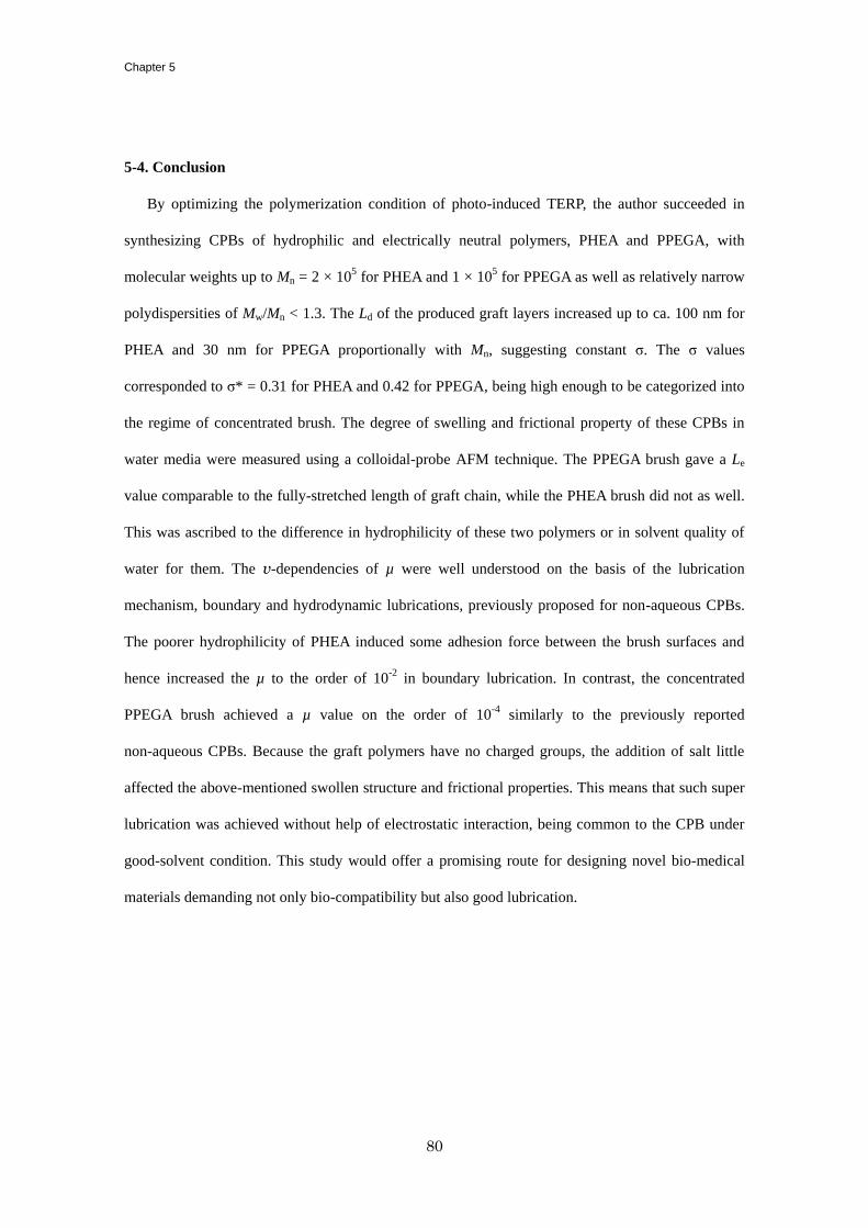
Chapter 5
80
5-4. Conclusion
By optimizing the polymerization condition of photo-induced TERP, the author succeeded in
synthesizing CPBs of hydrophilic and electrically neutral polymers, PHEA and PPEGA, with
molecular weights up to Mn = 2 × 10⁵ for PHEA and 1 × 10
5 for PPEGA as well as relatively narrow
polydispersities of Mw/Mn < 1.3. The Ld of the produced graft layers increased up to ca. 100 nm for
PHEA and 30 nm for PPEGA proportionally with Mn, suggesting constant σ. The σ values
corresponded to σ* = 0.31 for PHEA and 0.42 for PPEGA, being high enough to be categorized into
the regime of concentrated brush. The degree of swelling and frictional property of these CPBs in
water media were measured using a colloidal-probe AFM technique. The PPEGA brush gave a Le
value comparable to the fully-stretched length of graft chain, while the PHEA brush did not as well.
This was ascribed to the difference in hydrophilicity of these two polymers or in solvent quality of
water for them. The v-dependencies of µ were well understood on the basis of the lubrication
mechanism, boundary and hydrodynamic lubrications, previously proposed for non-aqueous CPBs.
The poorer hydrophilicity of PHEA induced some adhesion force between the brush surfaces and
hence increased the µ to the order of 10-2
in boundary lubrication. In contrast, the concentrated
PPEGA brush achieved a µ value on the order of 10-4
similarly to the previously reported
non-aqueous CPBs. Because the graft polymers have no charged groups, the addition of salt little
affected the above-mentioned swollen structure and frictional properties. This means that such super
lubrication was achieved without help of electrostatic interaction, being common to the CPB under
good-solvent condition. This study would offer a promising route for designing novel bio-medical
materials demanding not only bio-compatibility but also good lubrication.
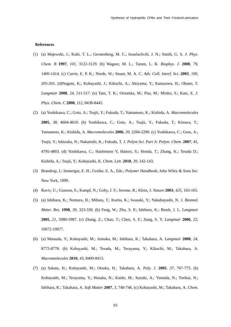
Synthesis of Hydrophilic CPBs and Their Friction/Lubrication
81
References
(1) (a) Majewski, J.; Kuhi, T. L.; Gerstenberg, M. C.; Israelachvili, J. N.; Smith, G. S. J. Phys.
Chem. B 1997, 101, 3122-3129. (b) Wagner, M. L.; Tamm, L. K. Biophys. J. 2000, 79,
1400-1414. (c) Currie, E. P. K.; Norde, W.; Stuart, M. A. C. Adv. Coll. Interf. Sci. 2003, 100,
205-265. (d)Nagase, K.; Kobayashi, J.; Kikuchi, A.; Akiyama, Y.; Kanazawa, H.; Okano, T.
Langmuir 2008, 24, 511-517. (e) Tam, T. K.; Ornatska, M.; Pita, M.; Minko, S.; Katz, E. J.
Phys. Chem. C 2008, 112, 8438-8445.
(2) (a) Yoshikawa, C.; Goto, A.; Tsujii, Y.; Fukuda, T.; Yamamoto, K.; Kishida, A. Macromolecules
2005, 38, 4604-4610. (b) Yoshikawa, C.; Goto, A.; Tsujii, Y.; Fukuda, T.; Kimura, T.;
Yamamoto, K.; Kishida, A. Macromolecules 2006, 39, 2284-2290. (c) Yoshikawa, C.; Goto, A.;
Tsujii, Y.; Ishizuka, N.; Nakanishi, K.; Fukuda, T. J. Polym Sci. Part A: Polym. Chem. 2007, 45,
4795-4803. (d) Yoshikawa, C.; Hashimoto Y, Hattori, S.; Honda, T.; Zhang, K.; Terada D.;
Kishida, A.; Tsujii, Y.; Kobayashi, K. Chem. Lett. 2010, 39, 142-143.
(3) Brandrup, J.; Immergut, E. H.; Grulke, E. A., Eds.; Polymer Handbook; John Wiley & Sons Inc:
New York, 1999.
(4) Raviv, U.; Giasson, S.; Kampf, N.; Gohy, J. F.; Jerome, R.; Klein, J. Nature 2003, 425, 163-165.
(5) (a) Ishihara, K.; Nomura, H.; Mihara, T.; Kurita, K.; Iwasaki, Y.; Nakabayashi, N. J. Biomed.
Mater. Res. 1998, 39, 323-330. (b) Feng, W.; Zhu, S. P.; Ishihara, K.; Brash, J. L. Langmuir
2005, 21, 5980-5987. (c) Zhang, Z.; Chao, T.; Chen, S. F.; Jiang, S. Y. Langmuir 2006, 22,
10072-10077.
(6) (a) Matsuda, Y.; Kobayashi, M.; Annaka, M.; Ishihara, K.; Takahara, A. Langmuir 2008, 24,
8772-8778. (b) Kobayashi, M.; Terada, M.; Terayama, Y.; Kikuchi, M.; Takahara, A.
Macromolecules 2010, 43, 8409-8415.
(7) (a) Sakata, H.; Kobayashi, M.; Otsuka, H.; Takahara, A. Poly. J. 2005. 37, 767-775. (b)
Kobayashi, M.; Terayama, Y.; Hosaka, N.; Kaido, M.; Suzuki, A.; Yamada, N.; Torikai, N.;
Ishihara, K.; Takahara, A. Soft Matter 2007, 3, 740-746. (c) Kobayashi, M.; Takahara, A. Chem.
Chapter 5
82
Rec. 2010, 10, 208-216. (d) Ishikawa, T.; Kobayashi, M.; Takahara, A. ACS Appl. Mater. Interf.
2010, 2, 1120-1128.
(8) Chen, M.; Briscoe, W. H.; Armes, S, P.; Klein, J. Science 2009, 323, 1698-1701.
(9) (a) Han, S.; Hagiwara, M.; Ishizone, T. Macromolecules 2003, 36, 8312-8319. (b) Tanaka, M.;
Mochizuki, A. J. Biomed. Mater. Res. Part A 2004, 68A, 684-695. (c) Hua, F. J.; Jiang, X. G.; Li,
D. J.; Zhao, B. J. Polym. Chem. Part A: Polym. Chem. 2006, 44, 2454-2467.
(10) (a) Yamago, S.; Iida, K.; Yoshida, J. J. Am. Chem. Soc. 2002, 124, 2874-2875. (b) Yamago, S.;
Lida, K.; Yoshida, J. J. Am. Chem. Soc. 2002, 124, 13666-13667. (c) Yamago, S.; Iida, K.;
Nakajima, M.; Yoshida, J. Macromolecules 2003, 36, 3793-3796. (d) Yamago, S. Chem. Rev.
2009, 109, 5051-5068.
(11) Coca, S.; Jasieczek, C. B.; Beers, K. L.; Matyjaszewski, K. J. Polym. Sci. Part A: Polym. Chem.
1998, 36, 1417-1424.
(12) Ohno, K.; Morinaga, T.; Koh, K.; Tsujii, Y.; Fukuda, T. Macromolecules 2005, 38, 2137-2142.
(13) Yamago, S.; Ukai, Y.; Matsumoto, A.; Nakamura, Y. J. Am. Chem. Soc. 2009, 131, 2100-2101.
(14) Kwak, Y.; Goto, A.; Fukuda, T.; Kobayashi, Y.; Yamago, S. Macromolecules 2006, 39,
4671-4679.
(15) Bell, W.; Colehamil, D. J.; Culshaw, P. N.; Mcqueen, A. E. D., Shenaikhatkhate, D. V.; Walton,
J. C.; Hails, J. E. J. Organomet. Chem. 1992, 430, 43-52.
(16) Kwak, Y.; Tezuka, M.; Goto, A.; Fukuda, T.; Yamago, S. Macromolecules 2007, 40, 1881-1885.
(17) (a) Tsujii, Y.; Ejaz, M.; Sato, K.; Goto, A.; Fukuda, T. Macromolecules 2001, 34, 8872-8878.
(b) Morinaga, T.; Ohkura, M.; Ohno, K.; Tsjii, Y.; Fukuda, T. Macromolecules 2007, 40,
1159-1164.
83
Chapter 6
Synthesis and Frictional Property of Thermo-Responsible Concentrated Polymer Brushes
6-1. Introduction
In Chapter 5, the CPBs of hydrophilic polymers were newly synthesized and super lubrication
was achieved for one of them in water media, which would offer a new surface modification
technique for bio-medical devices. Meanwhile, the ability to control and manipulate friction is
extraordinarily important in many applications ranging from bio-lubricating systems1 to
micromechanical devices.2 However, the understanding of friction especially in bio-systems,
3
achieving intelligent friction4 still remains great challenges for advanced applications.
Poly (N-isopropyl acrylamide) (PNIPAM) is one of the well known polymers with
thermo-responsibility in water media sharply changing its conformation and solubility, according to
a LCST-type phase separation around 32 ºC.5 Due to its transition temperature at around ambient and
body temperature of our living sphere, PNIPAM has been widely used ranging from the fundamental
studies on polymer-solution properties to application researches for bio-medical materials. As one of
the most intensively studied applications, PNIPAM was grafted on membrane surfaces to control cell
adhesion by changing the wettability of the outermost surfaces.6 However, those PNIPAM-grafted
membranes had insufficiently well organized, discouraging the closer fundamental study on
transitions in solubility, hydrophilicity, and lubricity.
In order to control the structural parameters, the surface-initiated LRP would be one of the most
useful approaches, as the author achieved in the former Chapters. The fabrication of CPB of
PNIPAM would offer us novel model surfaces not only to investigate the swelling and friction
properties of polymer brush as a function of temperature but also for the evolution of bio-lubricating
materials. In this study, CPB and SDPB of PNIPAM are fabricated through surface-initiated ATRP
and studied on their swelling and friction properties as a function of temperature to discuss the
Chapter 6
84
detailed mechanism of friction/lubrication and its temperature-induced transition.
6-2. Experiment
6-2-1. Materials
N-Isopropyl acrylamide (NIPAM, Wako Pure Chemicals, Japan, 98%) was recrystallized three
times from a toluene/hexane mixture prior to use. Copper(I) chloride (Cu(I)Cl, 99.9%), copper(II)
chloride (Cu(II)Cl2, 99.9%), dimethyl sulfoxide (DMSO) (dehydrated, 99%), allylamine (98%),
propylamine (98%), 2-chloropropionyl chloride (95%), and 3-chloropropyltriethoxysilane (CPT)
(97%) were purchased from Wako Pure Chemicals and used as received.
Tris[2-(dimethylamino)ethyl]amine (Me6TREN) was prepared as described in the literature.7
Triethoxysilane (99%) was obtained from Chisso Corp., Tokyo, Japan, and distilled before use. A
solution of platinum catalyst (Karstedt’s catalyst) (Pt-114, platinum content: 3 wt%) was received
from Johnson Matthey Catalysts, Royston, UK. All other reagents were used as received from
commercial sources.
6-2-2. Synthesis of N-propyl-2-chloropropanamide (PCP)
A free initiator, N-propyl-2-chloropropanamide (PCP), was synthesized by the amidation of
allylamine with 2-chloropropionyl chloride. 2-Chloropropionyl chloride (25 g, 197 mmol) was
added dropwise to a solution of propylamine (12 g, 204 mmol) and triethylamine (20 mL, 198
mmol) in dry THF (200 mL) at 0 °C. The mixture was magnetically stirred for 3 h at 0 °C and then
for another 10 h at room temperature. After the reaction, the solution was passed through a filter
paper, and the filtrate was evaporated to dryness under reduced pressure. The residue was diluted
with chloroform (200 mL) and washed twice with 1 N HCl aqueous solution (2 200 mL), twice
with NaHCO3-saturated aqueous solution (2 200 mL), and with water (500 mL). After the solution
was dried over Na2SO4 and filtered off, the solvent was evaporated, giving a brown oil. This crude
product was subsequently purified by flash chromatography on a column of silica gel with a mixture
of hexane and ethyl acetate (5/1, v/v) as an eluent to yield PCP as a transparent liquid (32 g, 86%).
Synthesis and Friction of Thermo-Responsible CPBs
85
1H NMR (CDCl3): 0.95 (t, 3H, CH2CH3), 1.60 (m, 2H, CH3CH2CH2), 1.73 (d, 3H, CHCH3), 3.2 (q,
2H, CH2CH2NH), 4.40 (q, 1H, COCHClCH3), 6.8 (br, s, 1H, NH). 13
C NMR (CDCl3): 11.1
(CH3CH2), 22.4 (CHCH3), 22.5 (CH3CH2), 41.4 (CH2CH2NH), 55.8 (COCHClCH3), 169.4 (NHCO).
Anal. Calcd for C6H12NOCl: C, 46.21; H, 8.40; O, 10.69, N, 9.36, Cl, 23.70. Found: C, 46.37; H,
8.46; O, 10.72, N, 4.38, Cl, 11.53.
6-2-3. Synthesis of 2-chloro-N-(3-(triethoxysilyl)propyl)propanamide (CTP)
A surface-immobilizable initiator, 2-chloro-N-(3-(triethoxysilyl)propyl)propanamide (CTP),
was newly designed and synthesized via the two-step reaction as follows. First,
N-allyl-2-chloropropanamide was synthesized according to the same procedure as described for PCP.
Finally, a colorless oil was obtained with a 90% yield. 1H NMR (CDCl3): 1.75 (d, 3H, CHCH3),
3.91 (q, 2H, CHCH2NH), 4.45 (q, 1H, COCHClCH3), 5.15-5.25 (m, 2H, CH2=CH), 5.80-5.92 (m,
1H, CH2=CH), 6.82 (s, 1H, NH). 13
C NMR (CDCl3): 22.6 (CHCH3), 42.0 (CHCH2NH), 55.7
(COCHClCH3), 116.5 (CH2=CH), 133.3 (CH2=CH), 169.3 (NHCO). Anal. Calcd for C6H10NOCl: C,
48.82; H, 6.83; O, 10.84, N, 9.49, Cl, 24.02. Found: C, 46.93; H, 6.62; O, 12.00, N, 9.03, Cl, 24.45.
Then, CTP was synthesized via the hydrosilylation reaction between
N-allyl-2-chloropropanamide and triethoxysilane in the presence of Karstedt’s catalyst. The reaction
was carried out in a glovebox purged with argon gas. In brief, N-allyl-2-chloropropanamide (15 g,
101 mmol) and dry toluene (50 mL) were charged into a two-neck round-bottom flask equipped with
a magnetic stir bar and a rubber septum. Freshly distilled triethoxysilane (100 mL, 0.54 mol) and
subsequently a solution of Karstedt’s catalyst (200 μL) was added dropwise into the flask by a
syringe. The reaction mixture was magnetically stirred under an argon atmosphere at room
temperature for 48 h. The complete consumption of N-allyl-2-chloropropanamide was confirmed by
1H NMR spectroscopy. Excess triethoxysilane and toluene were removed under vacuum at 50 °C to
afford CTP as a slightly yellow liquid in a quantitative yield. 1H NMR (CDCl3): 0.65 (t, 2H,
SiCH2), 1.25 (t, 9H, CH3CH2OSi), 1.60 (m, 2H, CH2CH2CH2), 1.75 (d, 3H, CHCH3), 3.30 (q, 2H,
CHCH2NH), 3.84 (q, 6H, CH3 2OSi), 4.30 (q, 1H, COCHClCH3), 6.80 (s, 1H, NH). 13
C NMR
Chapter 6
86
(CDCl3): 7.5 (SiCH2), 18.2 (SiOCH2CH3), 22.7 (CH2CH2CH2, CHCH3), 42.0 (CH2CH2NH), 56.0
(COCHClCH3), 58.4 (SiOCH2CH3), 169.3 (NHCO). Anal. Calcd for C12H26 NO4ClSi: C, 46.21; H,
8.40; N, 4.49, Cl, 11.37. Found: C, 46.37; H, 8.46; N, 4.38, Cl, 11.53.
6-2-4. Synthesis of PNIPAM Brushes via Surface Initiated ATRP
A silicon wafer (Ferrotec Corp., Japan, thickness 0.5 mm) treated with ultraviolet (UV) / ozone
for 15 min was immersed for 12 h at room temperature in an ethanol solution containing CTP/CPT
mixture (1 wt%) and 28%-aqueous ammonium (5 wt%) and then copiously rinsed with ethanol.
Under an argon atmosphere, the CTP-immobilized wafer was immersed in a degassed DMSO
solution of NIPAM (3.0 M), Cu(I)Cl (2.9 mM), Cu(II)Cl2 (1.0 mM), Me6TREN (3.9 mM), and PCP
(1.5 mM) at room temperature for a given time. PCP was used as a “sacrificial” free initiator
producing a free polymer as a useful reference in molecular weight and molecular weight
distribution for the graft polymer.8 The polymerization solution was directly analyzed by gel
permeation chromatography (GPC) and 1H NMR to estimate the molecular weights of free polymers
and the monomer conversion, respectively. The as-prepared sample was rinsed in a Soxhlet
apparatus with methanol for at least 10 h to remove physisorbed free polymers and impurities. The
thicknesses of dried and swollen PNIPAM brushes were measured by ellipsometry and AFM. No
characteristic structure was observed by AFM on the surfaces either before or after graft
polymerization, suggesting that the initiating groups were immobilized on the surface randomly in a
scale smaller than the AFM resolution.
The same protocol was used to prepare PNIPAM brushes on silica spheres (SiP, HIPRESICA SP,
diameter 10 µm, obtained from Ube Nitto Kasei Co., Ltd.), which were suspended with help of
magnetic stirring in the mixture solution of surface initiator and then the polymerization solution.
The brush-modified silica particles thus obtained were rinsed by repeated dispersion/centrifugation
cycles in methanol.
6-2-5. Frictional Force Measurement by AFM
An AFM (JPK Instruments Inc., Germany, Nano Wizard) was used to characterize the structure
Synthesis and Friction of Thermo-Responsible CPBs
87
and properties of PNIPAM brush surfaces. For the measurement of equilibrium swollen thickness, a
bare unmodified SiP was attached on a V-shaped cantilever (Olympus Optical Co., Ltd., Japan, kn =
0.15 N/m) with two-component epoxy resin adhesive and used as a probe. The detailed procedures
of the AFM measurements were described in section 2-2-3. For the measurement of friction and
adhesive forces between the brush surfaces, a brush-modified SiP prepared above was attached on a
rectangular-shaped cantilever (Olympus Optical Co., Ltd, vertical spring constant, kn = 0.73 N/m,
lateral spring constant, ks = 86 N/m) and used as aprobe.
6-2-6. Other Measurement
The GPC analysis for PNIPAM was made on a Tosoh CCP & 8020 series high-speed liquid
chromatograph (Tokyo, Japan) equipped with a Tosoh differential refractometer RI-8020. DMF
containing 10 mM LiBr was used as an eluent with a flow rate of 0.8 mL/min (40 °C). Two Shodex
gel columns LF804 (300 8.0 mm; bead size = 6 mm; pore size 20 - 3000 Å) (Tokyo) were
installed and calibrated with poly (methyl methacrylate) (PMMA) standards. The Mw/Mn value was
estimated according to this calibration. To estimate the absolute value of Mn, sample detection was
also made with a multiangle laser light scattering (MALLS) detector, a Wyatt Technology DAWN
EOS (Santa Barbara, CA), equipped with a Ga-As laser λ = 690 nm. The refractive index increment
dn/dc was determined to be 0.0774 mL·g-1
by a Wyatt Technology OPTILAB DSP differential
refractometer.
The thicknesses of the PNIPAM-brush layers in dry state (Ld) were determined by a compensator
rotating, spectroscopic ellipsometer (M-2000U, J.A. Woolam, Lincoln, NE) equipped with D2 and
QTH lamps. The polarizer angle was 45°, and the incident angles were 60°, 65°, and 70°. The
thickness was calculated using the refractive index determined for the spin-cast PNIPAM film with a
thickness of ca. 200 nm.
1H (300 MHz) and
13C NMR (75 MHz) spectra were obtained on a JEOL/AL300 spectrometer.
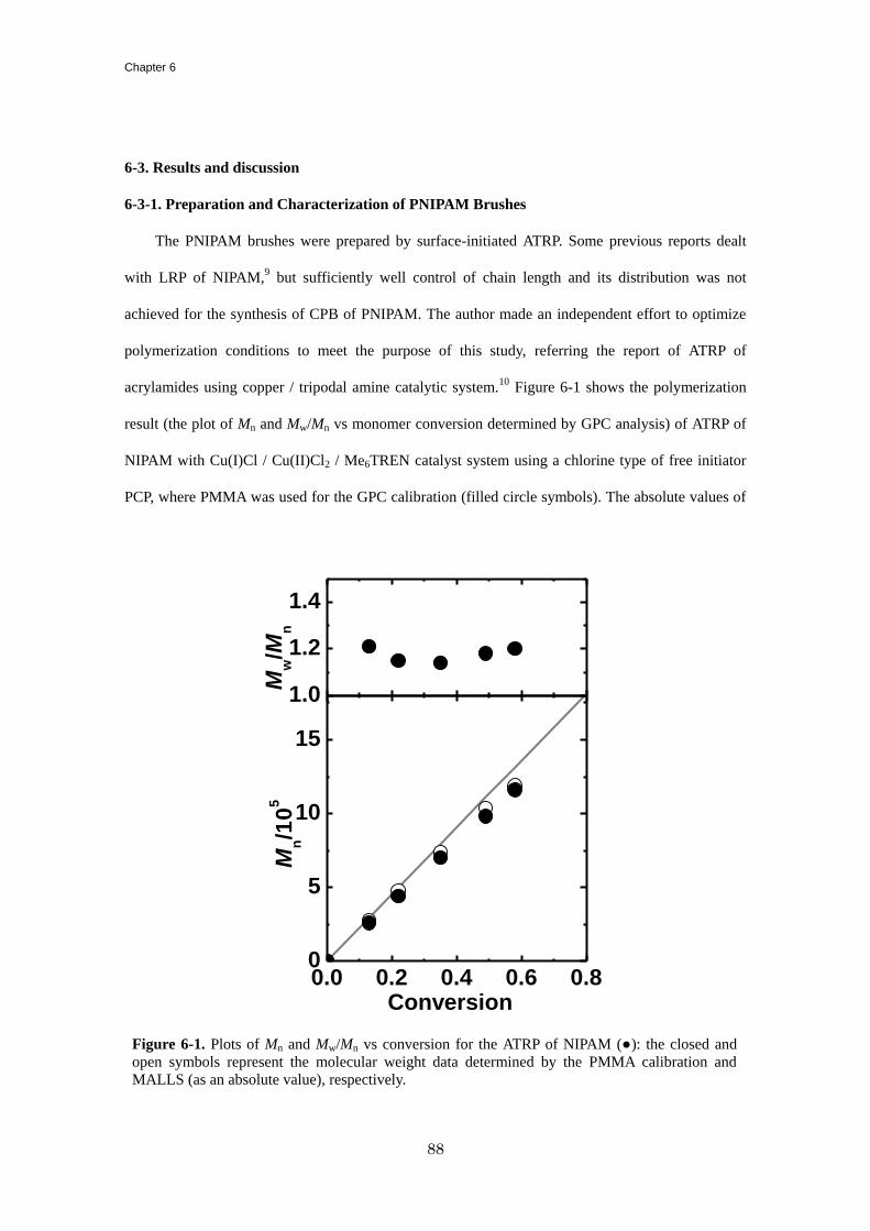
Chapter 6
88
6-3. Results and discussion
6-3-1. Preparation and Characterization of PNIPAM Brushes
The PNIPAM brushes were prepared by surface-initiated ATRP. Some previous reports dealt
with LRP of NIPAM,9 but sufficiently well control of chain length and its distribution was not
achieved for the synthesis of CPB of PNIPAM. The author made an independent effort to optimize
polymerization conditions to meet the purpose of this study, referring the report of ATRP of
acrylamides using copper / tripodal amine catalytic system.10
Figure 6-1 shows the polymerization
result (the plot of Mn and Mw/Mn vs monomer conversion determined by GPC analysis) of ATRP of
NIPAM with Cu(I)Cl / Cu(II)Cl2 / Me6TREN catalyst system using a chlorine type of free initiator
PCP, where PMMA was used for the GPC calibration (filled circle symbols). The absolute values of
1.0
1.2
1.4
0.0 0.2 0.4 0.6 0.80
5
10
15
Mw/M
n
Mn/1
05
Conversion
Figure 6-1. Plots of Mn and Mw/Mn vs conversion for the ATRP of NIPAM (●): the closed and
open symbols represent the molecular weight data determined by the PMMA calibration and
MALLS (as an absolute value), respectively.
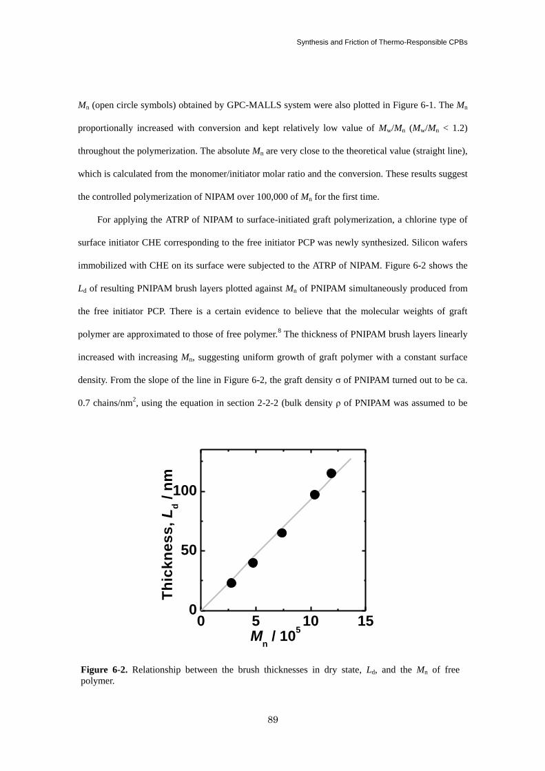
Synthesis and Friction of Thermo-Responsible CPBs
89
Mn (open circle symbols) obtained by GPC-MALLS system were also plotted in Figure 6-1. The Mn
proportionally increased with conversion and kept relatively low value of Mw/Mn (Mw/Mn < 1.2)
throughout the polymerization. The absolute Mn are very close to the theoretical value (straight line),
which is calculated from the monomer/initiator molar ratio and the conversion. These results suggest
the controlled polymerization of NIPAM over 100,000 of Mn for the first time.
For applying the ATRP of NIPAM to surface-initiated graft polymerization, a chlorine type of
surface initiator CHE corresponding to the free initiator PCP was newly synthesized. Silicon wafers
immobilized with CHE on its surface were subjected to the ATRP of NIPAM. Figure 6-2 shows the
Ld of resulting PNIPAM brush layers plotted against Mn of PNIPAM simultaneously produced from
the free initiator PCP. There is a certain evidence to believe that the molecular weights of graft
polymer are approximated to those of free polymer.8 The thickness of PNIPAM brush layers linearly
increased with increasing Mn, suggesting uniform growth of graft polymer with a constant surface
density. From the slope of the line in Figure 6-2, the graft density σ of PNIPAM turned out to be ca.
0.7 chains/nm2, using the equation in section 2-2-2 (bulk density ρ of PNIPAM was assumed to be
0 5 10 150
50
100
Th
ick
ne
ss
, L
d /
nm
Mn / 10
5
Figure 6-2. Relationship between the brush thicknesses in dry state, Ld, and the Mn of free
polymer.
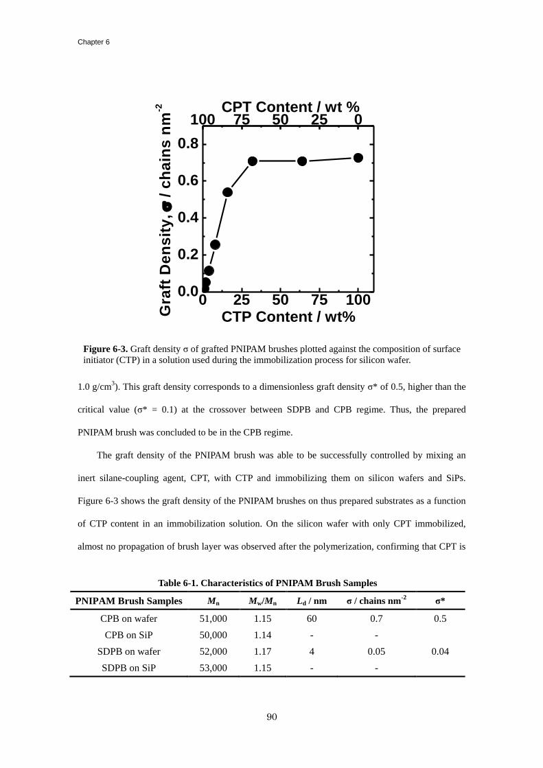
Chapter 6
90
1.0 g/cm3). This graft density corresponds to a dimensionless graft density σ* of 0.5, higher than the
critical value (σ* = 0.1) at the crossover between SDPB and CPB regime. Thus, the prepared
PNIPAM brush was concluded to be in the CPB regime.
The graft density of the PNIPAM brush was able to be successfully controlled by mixing an
inert silane-coupling agent, CPT, with CTP and immobilizing them on silicon wafers and SiPs.
Figure 6-3 shows the graft density of the PNIPAM brushes on thus prepared substrates as a function
of CTP content in an immobilization solution. On the silicon wafer with only CPT immobilized,
almost no propagation of brush layer was observed after the polymerization, confirming that CPT is
100 75 50 25 0
0 25 50 75 1000.0
0.2
0.4
0.6
0.8
Gra
ft D
en
sit
y,
/
ch
ain
s n
m-2
CTP Content / wt%
CPT Content / wt %
Figure 6-3. Graft density σ of grafted PNIPAM brushes plotted against the composition of surface
initiator (CTP) in a solution used during the immobilization process for silicon wafer.
Table 6-1. Characteristics of PNIPAM Brush Samples
PNIPAM Brush Samples Mn Mw/Mn Ld / nm σ / chains nm-2
σ*
CPB on wafer 51,000 1.15 60 0.7 0.5
CPB on SiP 50,000 1.14 - -
SDPB on wafer 52,000 1.17 4 0.05 0.04
SDPB on SiP 53,000 1.15 - -
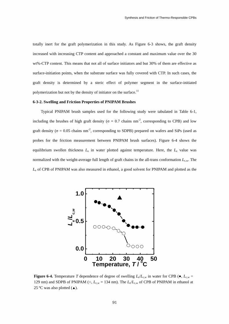
Synthesis and Friction of Thermo-Responsible CPBs
91
totally inert for the graft polymerization in this study. As Figure 6-3 shows, the graft density
increased with increasing CTP content and approached a constant and maximum value over the 30
wt%-CTP content. This means that not all of surface initiators and but 30% of them are effective as
surface-initiation points, when the substrate surface was fully covered with CTP. In such cases, the
graft density is determined by a steric effect of polymer segment in the surface-initiated
polymerization but not by the density of initiator on the surface.11
6-3-2. Swelling and Friction Properties of PNIPAM Brushes
Typical PNIPAM brush samples used for the following study were tabulated in Table 6-1,
including the brushes of high graft density (σ = 0.7 chains nm-2
, corresponding to CPB) and low
graft density (σ = 0.05 chains nm-2
, corresponding to SDPB) prepared on wafers and SiPs (used as
probes for the friction measurement between PNIPAM brush surfaces). Figure 6-4 shows the
equilibrium swollen thickness Le in water plotted against temperature. Here, the Le value was
normalized with the weight-average full length of graft chains in the all-trans conformation Lc,w. The
Le of CPB of PNIPAM was also measured in ethanol, a good solvent for PNIPAM and plotted as the
0 10 20 30 40 50
0.0
0.5
1.0
Le/L
c,w
Temperature, T / oC
Figure 6-4. Temperature T dependence of degree of swelling Le/Lc,w in water for CPB (●, Lc,w =
129 nm) and SDPB of PNIPAM (○, Lc,w = 134 nm). The Le/Lc,w of CPB of PNIPAM in ethanol at
25 ºC was also plotted (▲).
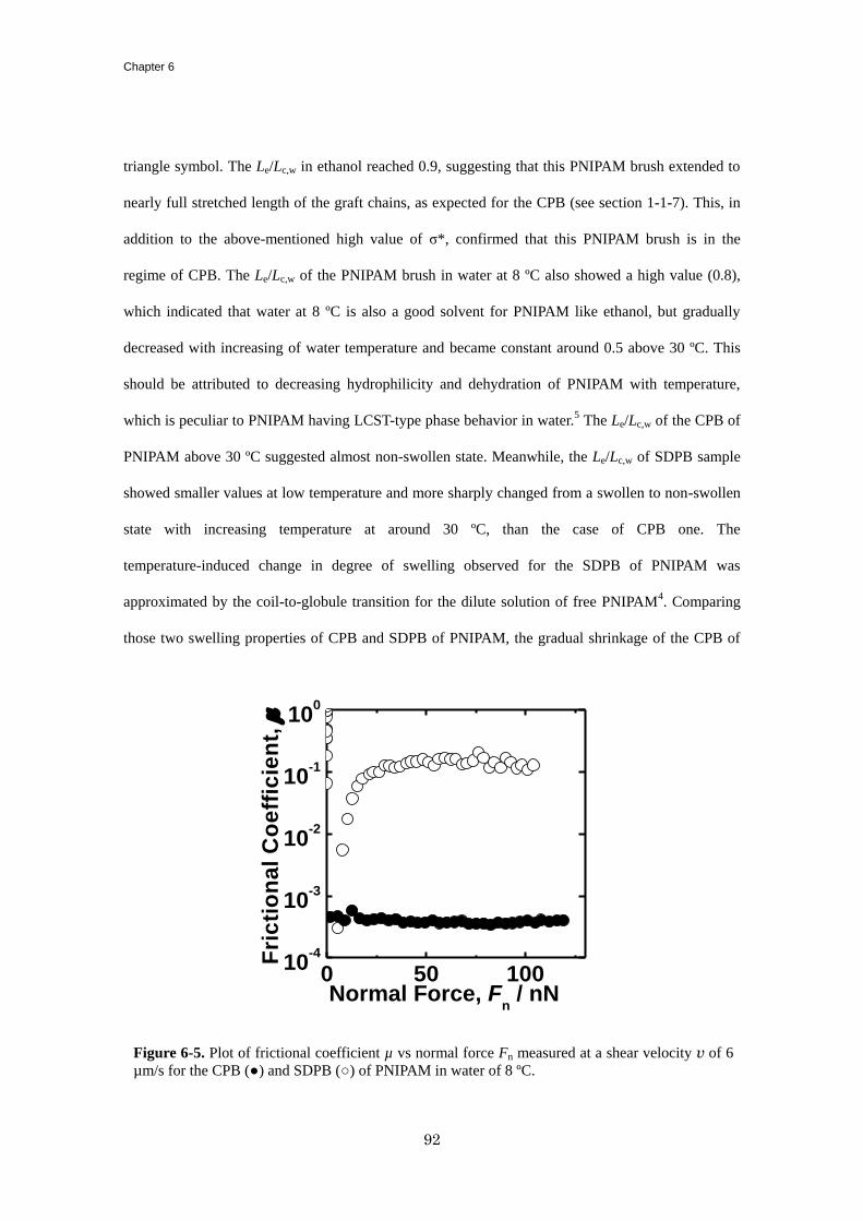
Chapter 6
92
triangle symbol. The Le/Lc,w in ethanol reached 0.9, suggesting that this PNIPAM brush extended to
nearly full stretched length of the graft chains, as expected for the CPB (see section 1-1-7). This, in
addition to the above-mentioned high value of σ*, confirmed that this PNIPAM brush is in the
regime of CPB. The Le/Lc,w of the PNIPAM brush in water at 8 ºC also showed a high value (0.8),
which indicated that water at 8 ºC is also a good solvent for PNIPAM like ethanol, but gradually
decreased with increasing of water temperature and became constant around 0.5 above 30 ºC. This
should be attributed to decreasing hydrophilicity and dehydration of PNIPAM with temperature,
which is peculiar to PNIPAM having LCST-type phase behavior in water.5 The Le/Lc,w of the CPB of
PNIPAM above 30 ºC suggested almost non-swollen state. Meanwhile, the Le/Lc,w of SDPB sample
showed smaller values at low temperature and more sharply changed from a swollen to non-swollen
state with increasing temperature at around 30 ºC, than the case of CPB one. The
temperature-induced change in degree of swelling observed for the SDPB of PNIPAM was
approximated by the coil-to-globule transition for the dilute solution of free PNIPAM4. Comparing
those two swelling properties of CPB and SDPB of PNIPAM, the gradual shrinkage of the CPB of
0 50 10010
-4
10-3
10-2
10-1
100
Fri
cti
on
al
Co
eff
icie
nt,
m
Normal Force, Fn / nN
Figure 6-5. Plot of frictional coefficient µ vs normal force Fn measured at a shear velocity v of 6
µm/s for the CPB (●) and SDPB (○) of PNIPAM in water of 8 ºC.
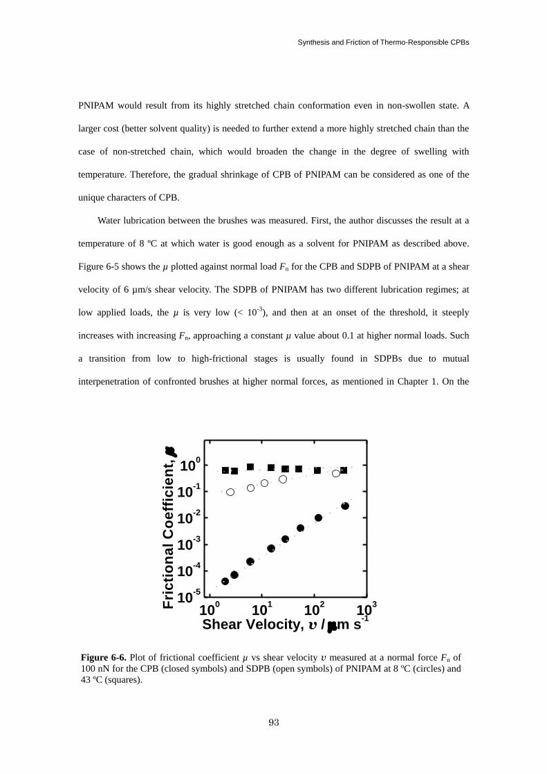
Synthesis and Friction of Thermo-Responsible CPBs
93
PNIPAM would result from its highly stretched chain conformation even in non-swollen state. A
larger cost (better solvent quality) is needed to further extend a more highly stretched chain than the
case of non-stretched chain, which would broaden the change in the degree of swelling with
temperature. Therefore, the gradual shrinkage of CPB of PNIPAM can be considered as one of the
unique characters of CPB.
Water lubrication between the brushes was measured. First, the author discusses the result at a
temperature of 8 ºC at which water is good enough as a solvent for PNIPAM as described above.
Figure 6-5 shows the µ plotted against normal load Fn for the CPB and SDPB of PNIPAM at a shear
velocity of 6 µm/s shear velocity. The SDPB of PNIPAM has two different lubrication regimes; at
low applied loads, the µ is very low (< 10-3
), and then at an onset of the threshold, it steeply
increases with increasing Fn, approaching a constant µ value about 0.1 at higher normal loads. Such
a transition from low to high-frictional stages is usually found in SDPBs due to mutual
interpenetration of confronted brushes at higher normal forces, as mentioned in Chapter 1. On the
100
101
102
103
10-5
10-4
10-3
10-2
10-1
100
Fri
cti
on
al
Co
eff
icie
nt,
m
Shear Velocity, v / mm s-1
Figure 6-6. Plot of frictional coefficient µ vs shear velocity v measured at a normal force Fn of
100 nN for the CPB (closed symbols) and SDPB (open symbols) of PNIPAM at 8 ºC (circles) and
43 ºC (squares).
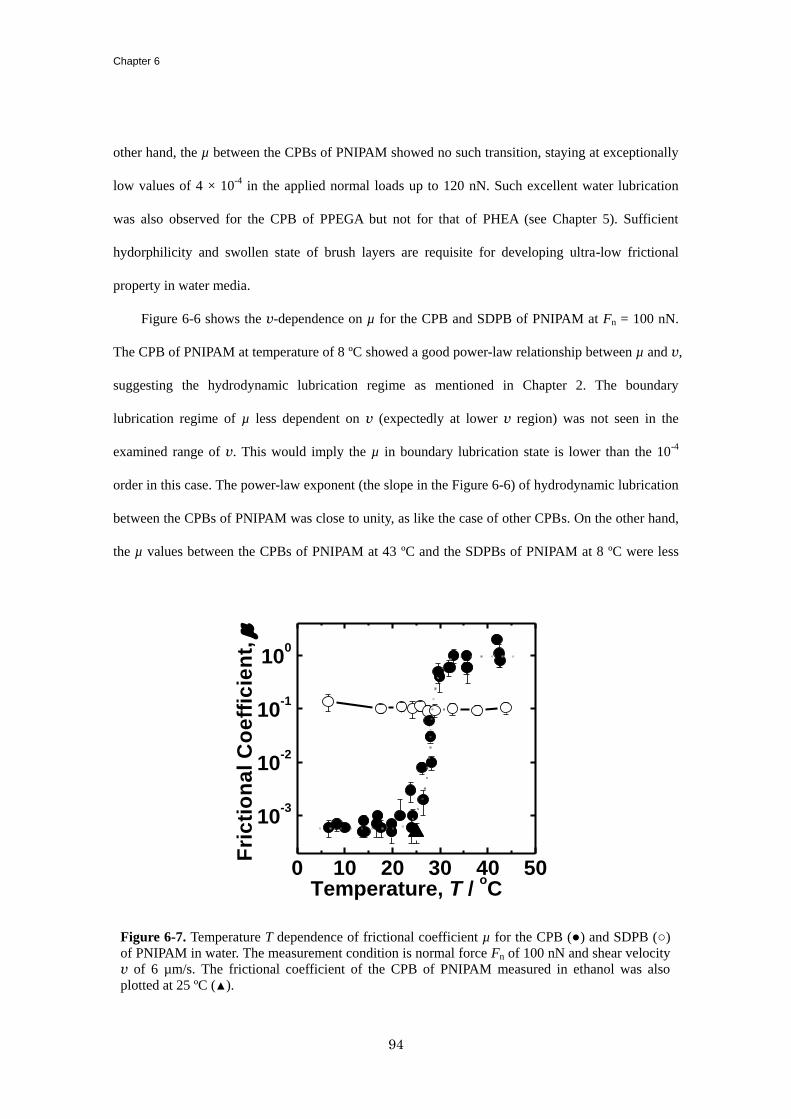
Chapter 6
94
other hand, the µ between the CPBs of PNIPAM showed no such transition, staying at exceptionally
low values of 4 × 10⁻⁴
in the applied normal loads up to 120 nN. Such excellent water lubrication
was also observed for the CPB of PPEGA but not for that of PHEA (see Chapter 5). Sufficient
hydorphilicity and swollen state of brush layers are requisite for developing ultra-low frictional
property in water media.
Figure 6-6 shows the v-dependence on µ for the CPB and SDPB of PNIPAM at Fn = 100 nN.
The CPB of PNIPAM at temperature of 8 ºC showed a good power-law relationship between µ and v,
suggesting the hydrodynamic lubrication regime as mentioned in Chapter 2. The boundary
lubrication regime of µ less dependent on v (expectedly at lower v region) was not seen in the
examined range of v. This would imply the µ in boundary lubrication state is lower than the 10-4
order in this case. The power-law exponent (the slope in the Figure 6-6) of hydrodynamic lubrication
between the CPBs of PNIPAM was close to unity, as like the case of other CPBs. On the other hand,
the µ values between the CPBs of PNIPAM at 43 ºC and the SDPBs of PNIPAM at 8 ºC were less
0 10 20 30 40 50
10-3
10-2
10-1
100
F
ric
tio
na
l C
oe
ffic
ien
t, m
Temperature, T / oC
Figure 6-7. Temperature T dependence of frictional coefficient µ for the CPB (●) and SDPB (○)
of PNIPAM in water. The measurement condition is normal force Fn of 100 nN and shear velocity
v of 6 µm/s. The frictional coefficient of the CPB of PNIPAM measured in ethanol was also
plotted at 25 ºC (▲).
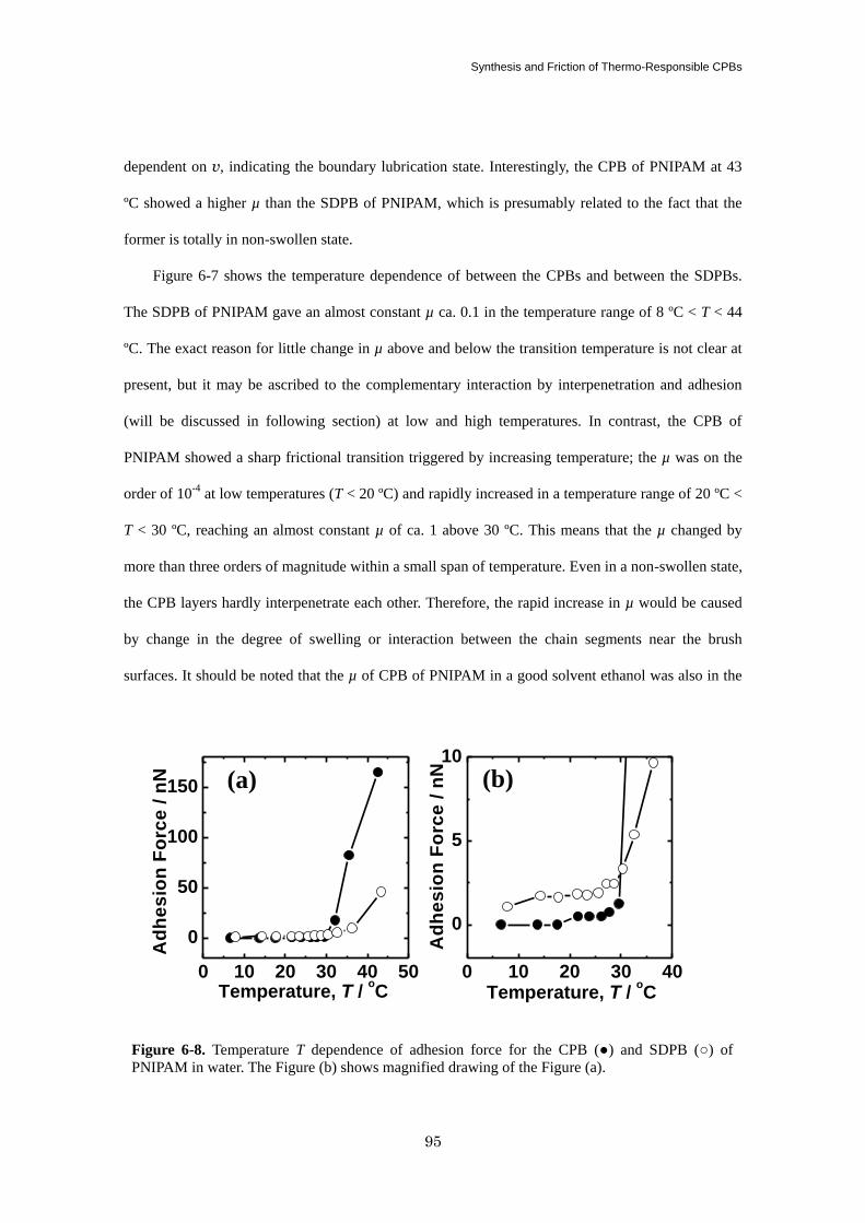
Synthesis and Friction of Thermo-Responsible CPBs
95
dependent on v, indicating the boundary lubrication state. Interestingly, the CPB of PNIPAM at 43
ºC showed a higher µ than the SDPB of PNIPAM, which is presumably related to the fact that the
former is totally in non-swollen state.
Figure 6-7 shows the temperature dependence of between the CPBs and between the SDPBs.
The SDPB of PNIPAM gave an almost constant µ ca. 0.1 in the temperature range of 8 ºC < T < 44
ºC. The exact reason for little change in µ above and below the transition temperature is not clear at
present, but it may be ascribed to the complementary interaction by interpenetration and adhesion
(will be discussed in following section) at low and high temperatures. In contrast, the CPB of
PNIPAM showed a sharp frictional transition triggered by increasing temperature; the µ was on the
order of 10-4
at low temperatures (T < 20 ºC) and rapidly increased in a temperature range of 20 ºC <
T < 30 ºC, reaching an almost constant µ of ca. 1 above 30 ºC. This means that the µ changed by
more than three orders of magnitude within a small span of temperature. Even in a non-swollen state,
the CPB layers hardly interpenetrate each other. Therefore, the rapid increase in µ would be caused
by change in the degree of swelling or interaction between the chain segments near the brush
surfaces. It should be noted that the µ of CPB of PNIPAM in a good solvent ethanol was also in the
Figure 6-8. Temperature T dependence of adhesion force for the CPB (●) and SDPB (○) of
PNIPAM in water. The Figure (b) shows magnified drawing of the Figure (a).
0 10 20 30 40 50
0
50
100
150
Ad
he
sio
n F
orc
e /
nN
Temperature, T / oC
(b)(a)
Ad
he
sio
n F
orc
e /
nN
Temperature, T / oC
0 10 20 30 40
0
5
10
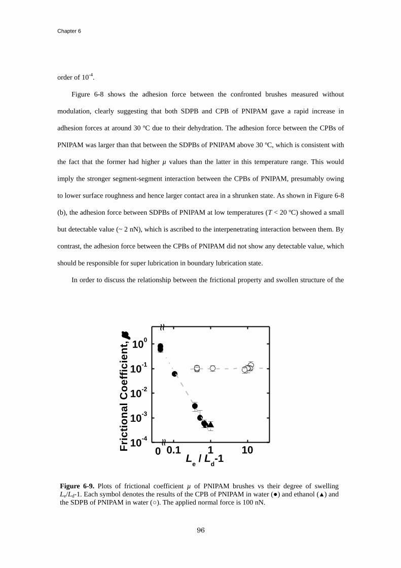
Chapter 6
96
order of 10-4
.
Figure 6-8 shows the adhesion force between the confronted brushes measured without
modulation, clearly suggesting that both SDPB and CPB of PNIPAM gave a rapid increase in
adhesion forces at around 30 ºC due to their dehydration. The adhesion force between the CPBs of
PNIPAM was larger than that between the SDPBs of PNIPAM above 30 ºC, which is consistent with
the fact that the former had higher µ values than the latter in this temperature range. This would
imply the stronger segment-segment interaction between the CPBs of PNIPAM, presumably owing
to lower surface roughness and hence larger contact area in a shrunken state. As shown in Figure 6-8
(b), the adhesion force between SDPBs of PNIPAM at low temperatures (T < 20 ºC) showed a small
but detectable value (~ 2 nN), which is ascribed to the interpenetrating interaction between them. By
contrast, the adhesion force between the CPBs of PNIPAM did not show any detectable value, which
should be responsible for super lubrication in boundary lubrication state.
In order to discuss the relationship between the frictional property and swollen structure of the
10-4
10-3
10-2
10-1
100
0.1 1 10
~~~
Fri
cti
on
al
Co
eff
icie
nt,
m
Le / L
d-1
0
~
Figure 6-9. Plots of frictional coefficient µ of PNIPAM brushes vs their degree of swelling
Le/Ld-1. Each symbol denotes the results of the CPB of PNIPAM in water (●) and ethanol (▲) and
the SDPB of PNIPAM in water (○). The applied normal force is 100 nN.
Synthesis and Friction of Thermo-Responsible CPBs
97
PNIPAM brushes, the µ of SDPBs and CPBs of PNIPAM were plotted against the degree of swelling,
Le/Ld-1, in Figure 6-9 in double logarithmic scale. As mentioned in Chapter 2, the degree of swelling
plays crucial role in determining friction in the hydrodynamic lubrication but little affect the
boundary lubrication state. In fact, the SDPB of PNIPAM gave little dependency in the studied
condition, in which it was in boundary lubrication state as already discussed in Figure 6-6. In
contrast, the CPBs of PNIPAM showed good scaling below 30 ºC. This indicates the hydrodynamic
lubrication state in this temperature range. The increase of frictional coefficient in the temperature
range of 20 ºC < T < 30 ºC in Figure 6-7 is attributed to gradual shrinking of the brush layer. The
exponent in this scaling was about -2.5, which is presumably understood by the change in the degree
of swelling simultaneously affecting the viscosity and thickness of effective hydrodynamic
lubrication layer as shown by Equation (2-5).
6-4. Conclusion
The PNIPAM brushes were synthesized via surface-initiated ATRP, and their graft densities
were widely controlled by changing the density of initiator on the surface from the SDPB to CPB
regimes. The CPB of PNIPAM in water of 8 ºC had nearly fully stretched chain conformation and
Fn-independent µ on the order of 10-4
, achieving excellent water lubrication, similarly to the CPBs of
PPEGA in Chapter 5. The v-dependence of µ revealed that under the studied condition, the CPB of
PNIPAM was in the hydrodynamic lubrication state, while the SDPB of PNIPAM was in the
boundary lubrication one. Both brushes showed swelling/shrinking behaviors with temperature
owing to the LCST-type hydration/dehydration. However, the swelling/shrinking curve of the CPB
of PNIPAM was broader than that of the SDPB of PNIPAM, reflecting their highly stretched chain
conformation. The CPB of PNIPAM showed a rapid increase in µ in a small range of 20 ºC < T < 30
ºC. This sharp change like a transition was brought about by shrinkage of brush layer simultaneously
affecting the effective thickness and viscosity of lubricating brush layer. These results revealed that
the CPB of PNIPAM could control the lubrication by temperature, which would offer new insight

Chapter 6
98
into tribology of polymer-brush-modified surfaces.
Synthesis and Friction of Thermo-Responsible CPBs
99
References
(1) (a) Urbakh, H.; Klafter, J.; Gourdon, D.; Israelachvili, J. Nature 2004, 430, 525-528. (b) Moro,
T.; Takatori, Y.; Ishihara, K.; Konno, T.; Takigawa, Y.; Matsushita, T.; Chung, U. IL.; Nakamura,
K.; Kawaguchi, H. Nat. Mater. 2004, 3, 829-836.
(2) (a) Durr, M.; Kentsch, J.; Muller, T.; Schnelle, T.; Stelzle, M. Electroporesis 2003, 24, 722-731.
(b) Wang, T.; Kelly, K. W. J. Micromech. Microeng. 2005, 15, 81-90.
(3) (a) Lee, S.; Spencer, N. D. Science 2008, 319, 575-576. (b) Klein, J. Science 2009, 323, 47-48.
(4) (a) Forster, A. M.; Mays, J. W.; Kilbey, S. M. J. Polym. Sci. Part B: Polym. Phys. 2006, 44,
649-655. (b) Chang, D. P.; Dolbow, J. E.; Zauscher, S. Langmuir 2007, 23, 250-257. (c)
Nordgren, N.; Rutland, M. W. Nano Lett. 2009, 9, 2984-2990.
(5) Schild, H. G. Prog. Polym. Sci. 1992, 17, 163-249.
(6) (a) Mizutani, A.; Kikuchi, A.; Yamato, M.; Kanazawa, H.; Okano, T. Biomaterials 2008, 29,
2073-2081. (b) Nagase, K.; Kobayashi, J.; Okano, T. J. Royal Society Interface 2009, 6,
S293-S309.
(7) Ciampolini, M.; Nardi, N. Inorg. Chem. 1966, 5, 41-44.
(8) (a) Tsujii, Y.; Ejaz, M.; Sato, K.; Goto, A.; Fukuda, T. Macromolecules 2001, 34, 8872-8878.
(b) Morinaga, T.; Ohkura, M.; Ohno, K.; Tsjii, Y.; Fukuda, T. Macromolecules 2007, 40,
1159-1164.
(9) (a) Yusa, S.; Shimada, Y.; Mitsukami, Y.; Yamamoto, T.; Morishima, Y. Macromolecules 2004,
37, 7507-7513. (b) Convertine, A. J.; Ayres, N.; Scales, C. W.; Lowe, A. B.; McCormick, C. L.
Biomacromolecules 2004, 5, 1177-1180. (c) Bontempo, D.; Li, L. C.; Ly, T.; Brubaker, C. E.;
Maynard, H. D. Chem. Comm. 2005, 37, 4702-4704. (d) Gibbons, O.; Carrol, W. M.;
Aldabbagh, F.; Yamada, B. J. Polym. Sci. Part A: Polym. Chem. 2006, 44, 6410-6418.
(10) Teodorescu, M.; Matyjaszewski, K. Macromol. Rap. Comm. 2000, 21, 190-194.
(11) Yamamoto, S.; Ejaz, M.; Tsujii, Y.; Fukuda, T. Macromolecules 2000, 33, 5608-5612.

Chapter 6
100
101
Chapter 7
Synthesis of Well-defined Bottle Brushes with Concentrated-Brush Effect and Frictional
Property of Their Gel
7-1. Introduction
Concerning the lubrication mechanism of CPBs, it can be expected that the super lubrication of
CPBs is not developed with grafted polymer on flat wafer but also on porous surface, sphere particle,
clay, fiber, polymer, etc. Among them, grafted polymer (bottle brush polymer) can form gel material
(graft-type of gel) by cross-linking. Gel is one of the attracted polymeric materials for lubrication,
since it represents excellent lubrication system of body tissue (bio-tribology), such as joints, eyes,
vessels, etc, which are generating much interest of the research of biomedical materials.1 Osada et al.
found super lubrication in charged hydro-gel attaining the µ of 10-4
order in water media. 2
They
insist that electrostatic repulsion force derived from charged polymer network prevent the polymer
to attach to the friction surface to produce pure solvent layer which actually acts as effective
lubricant. Aside from their system, the lubrication mechanism of CPBs would provide further
lubricating gel materials without the help of electrostatic repulsion effect, as the CPB lubrication
depends on the conformation of brush structure rather than chemical structure.
Whether the super lubrication of CPB can be introduced to graft type of gel or not is totally
depends on the conformational structure of bottle brush polymer of gel network; the precise control
of graft chain and cross-linking. The structure of bottle brush polymer can be considered with
columnar model (Figure 7-1). The effective graft density, the number of graft chains per columnar
surfaces, decays along with the chain length. The shorter graft chains rather maintain the stretched
structure determined by the initial graft density on the stem polymer. As the required effective graft
density for CPB is over 0.1 (see section 2-3), the columnar model suggests us that the bottle brush
polymer exhibit CPB structure when consisted of grafted chains on each monomer segment of stem
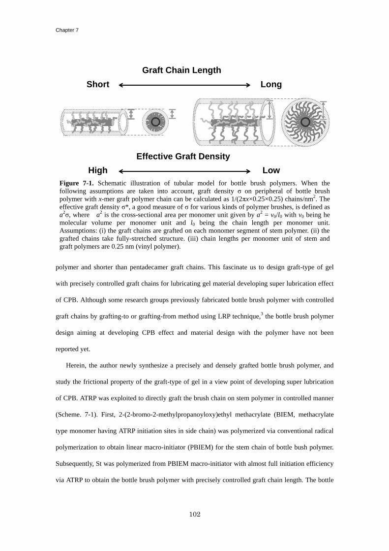
Chapter 7
102
polymer and shorter than pentadecamer graft chains. This fascinate us to design graft-type of gel
with precisely controlled graft chains for lubricating gel material developing super lubrication effect
of CPB. Although some research groups previously fabricated bottle brush polymer with controlled
graft chains by grafting-to or grafting-from method using LRP technique,3 the bottle brush polymer
design aiming at developing CPB effect and material design with the polymer have not been
reported yet.
Herein, the author newly synthesize a precisely and densely grafted bottle brush polymer, and
study the frictional property of the graft-type of gel in a view point of developing super lubrication
of CPB. ATRP was exploited to directly graft the brush chain on stem polymer in controlled manner
(Scheme. 7-1). First, 2-(2-bromo-2-methylpropanoyloxy)ethyl methacrylate (BIEM, methacrylate
type monomer having ATRP initiation sites in side chain) was polymerized via conventional radical
polymerization to obtain linear macro-initiator (PBIEM) for the stem chain of bottle bush polymer.
Subsequently, St was polymerized from PBIEM macro-initiator with almost full initiation efficiency
via ATRP to obtain the bottle brush polymer with precisely controlled graft chain length. The bottle
Figure 7-1. Schematic illustration of tubular model for bottle brush polymers. When the
following assumptions are taken into account, graft density σ on peripheral of bottle brush
polymer with x-mer graft polymer chain can be calculated as 1/(2πx×0.25×0.25) chains/nm2. The
effective graft density σ*, a good measure of σ for various kinds of polymer brushes, is defined as
a2σ, where a
2 is the cross-sectional area per monomer unit given by a
2 = v0/l0 with v0 being he
molecular volume per monomer unit and l0 being the chain length per monomer unit.
Assumptions: (i) the graft chains are grafted on each monomer segment of stem polymer. (ii) the
grafted chains take fully-stretched structure. (iii) chain lengths per monomer unit of stem and
graft polymers are 0.25 nm (vinyl polymer).
Effective Graft Density
Graft Chain Length
Short Long
High Low
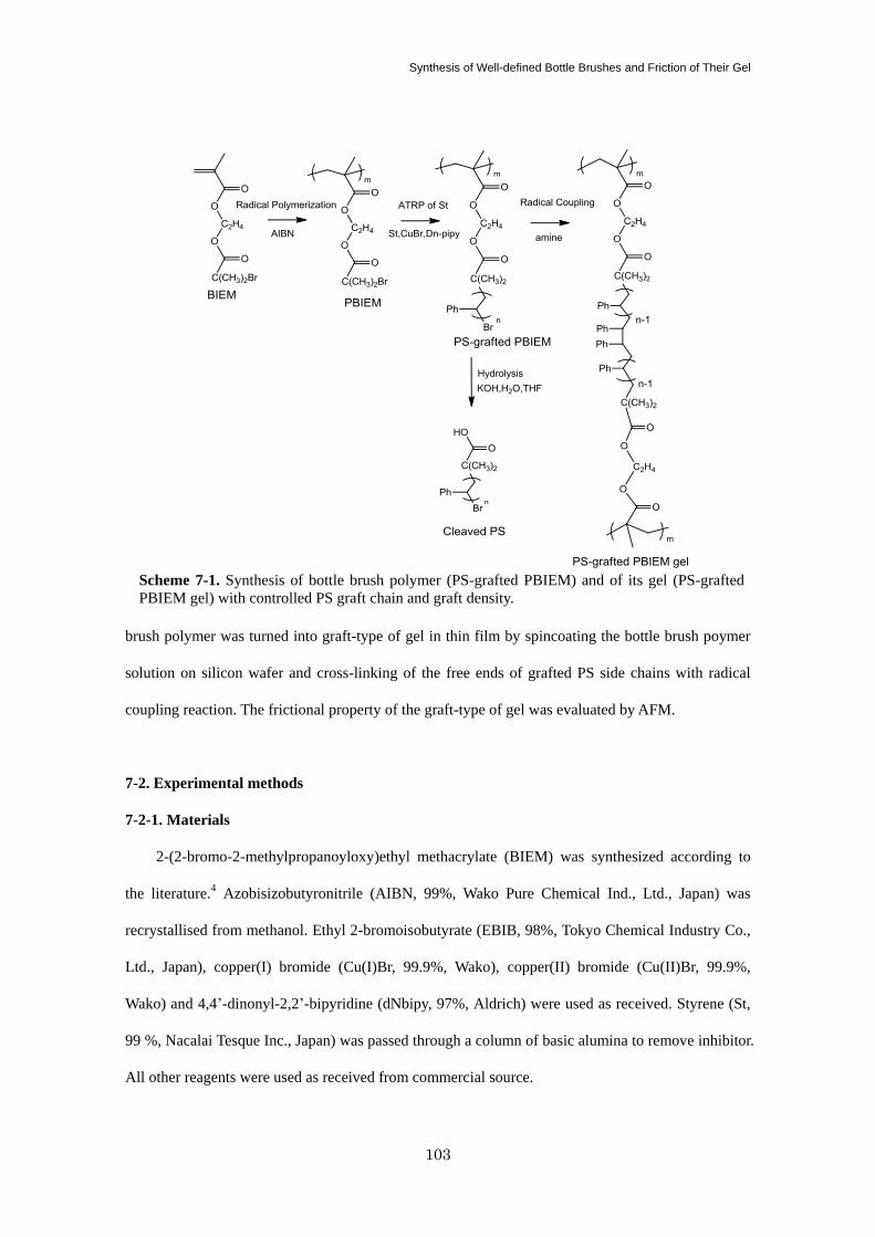
Synthesis of Well-defined Bottle Brushes and Friction of Their Gel
103
brush polymer was turned into graft-type of gel in thin film by spincoating the bottle brush poymer
solution on silicon wafer and cross-linking of the free ends of grafted PS side chains with radical
coupling reaction. The frictional property of the graft-type of gel was evaluated by AFM.
7-2. Experimental methods
7-2-1. Materials
2-(2-bromo-2-methylpropanoyloxy)ethyl methacrylate (BIEM) was synthesized according to
the literature.4 Azobisizobutyronitrile (AIBN, 99%, Wako Pure Chemical Ind., Ltd., Japan) was
recrystallised from methanol. Ethyl 2-bromoisobutyrate (EBIB, 98%, Tokyo Chemical Industry Co.,
Ltd., Japan), copper(I) bromide (Cu(I)Br, 99.9%, Wako), copper(II) bromide (Cu(II)Br, 99.9%,
Wako) and 4,4’-dinonyl-2,2’-bipyridine (dNbipy, 97%, Aldrich) were used as received. Styrene (St,
99 %, Nacalai Tesque Inc., Japan) was passed through a column of basic alumina to remove inhibitor.
All other reagents were used as received from commercial source.
Scheme 7-1. Synthesis of bottle brush polymer (PS-grafted PBIEM) and of its gel (PS-grafted
PBIEM gel) with controlled PS graft chain and graft density.
Chapter 7
104
7-2-2. Polymerization of BIEM
An anisole solution of BIEM (2.4 M) and AIBN (1.2 mM) was subjected to Schlenk flask and
then heated at 50 °C for 40 h under argon atmosphere to obtain polyBIEM (PBIEM) solution with
77% conversion determined from the gel permeation chromatography (GPC) peak area. The PBIEM,
after having purified by reprecipitation from an anisole solution into methanol, had a Mn of 467,000
and a Mw/Mn of 3.35 by PMMA-calibrated GPC.
7-2-3. ATRP of St from PBIEM
An anisole solution of St (4.6 M), PBIEM (21 mM), EBIB (free initiator, 2.3 mM), Cu(I)Br (46
mM), Cu(II)Br (2.3 mM) and dNbipy (92 mM) was subjected to Schlenk flask and then heated at
110 °C under argon atmosphere. After a prescribed time t, an aliquot of the solution was taken out
with a syringe and quenched to air. The reaction mixture was then diluted with tetrahydrofuran
(THF) and analyzed by GPC. The GPC curve showed two clearly divided peaks attributed to PS
grafted on PBIEM and free PS chain grown from EBIB respectively. The reaction mixture turned
into flabby soft gel when the conversion exceeded about 30%, due to a small proportion of
cross-linking by bimolecular termination reaction of growing PS chain from PBIEM. After the
gelation, the free PS chain was extracted by washing the gel with THF and analyzed by GPC. The
residual gel composed of PS grafted PBIEM was dried under vacuum and hydrolyzed as below. The
conversion of St was determined by 1H NMR analysis of the reaction mixture.
For preparation of PS grafted PBIEM for thin gel samples, the ATRP solution of St should be
stopped at relatively lower conversion before undesirable gelation. Free initiator EBIB also should
not be added to the solution due to the difficulty in separating the PS grafted PBIEM from free PS.
The PS grafted PBIEM for each gel sample was prepared as below.
PS grafted PBIEM for Gel 1 (Mp ~ 1,000)
An 8.0 g anisole solution of St (4.6 M), PBIEM (46 mM), Cu(I)Br (11 mM), Cu(II)Br (1.4 mM) and
dNbipy (23 mM) was subjected to Schlenk flask and then heated at 110 °C under argon atmosphere
for 5.0 h.
Synthesis of Well-defined Bottle Brushes and Friction of Their Gel
105
PS grafted PBIEM for Gel 2 (Mp ~ 1,300)
An 8.0 g anisole solution of St (4.6 M), PBIEM (46 mM), Cu(I)Br (11 mM), Cu(II)Br (1.4 mM) and
dNbipy (23 mM) was subjected to Schlenk flask and then heated at 110 °C under argon atmosphere
for 15.0 h.
PS grafted PBIEM for Gel 3 (Mp ~ 5,600)
An 8.0 g anisole solution of St (4.6 M), PBIEM (4.6 mM), Cu(I)Br (23 mM), Cu(II)Br (2.3 mM) and
dNbipy (46 mM) was subjected to Schlenk flask and then heated at 110 °C under argon atmosphere
for 7.0 h.
The purified PS grafted PBIEM for each gel sample was obtained by reprecipitation from an
anisole solution into methanol. The small portion of the PS grafted PBIEM was hydrolyzed as below
to measure the Mn and Mw/Mn of PS chain by GPC or matrix assisted laser desorption ionization time
of flight and mass spectrometry (MALDI-TOF MS, microflex & microflex LT, Bruker Daltonics Inc.,
USA) equipped with a nitrogen laser. The matrix used for the MALDI-TOF MS analysis was
dithranol.
7-2-4. Hydrolysis of PS chain from PS grafted PBIEM
The PS grafted PBIEM was dispersed (0.1 wt%) in 5 M KOH aqueous solution/THF/ethanol
(6/53/41 wt%) mixture. The system was sealed in glass tube and then heated at 100 °C for 12 h. The
residual solution was subjected to GPC analysis to examine the Mn and Mw/Mn of the cleaved PS and
hydrolysis efficiency of 90%. For MALDI-TOF MS analysis, the residue was diluted with 10 parts
chloroform and washed thrice with water, and then evaporation of solvent gave a polymer film of
cleaved PS.
7-2-5. Preparation of Thin Gel Film of PS Grafted PBIEM
PS grafted PBIEM was dissolved (5 wt%) in ethylbenzene containing 73 mM
tetrakis(dimethyl)ethylene. The thin gel film of PS grafted PBIEM was obtained by spincasting the
PS grafted PBIEM solution onto a silicon wafer (Ferrotec Corp., Japan, thickness 0.5 mm) using a
spin coater at spinning speeds of 500 rpm for 5 s and subsequently 3000 rpm for 30 s, followed by
Chapter 7
106
evaporation in vacuum for 10 min and annealing at 120 °C for 1 h in argon atmosphere to obtain
water insoluble PS grafted PBIEM gel film. The film was immersed in THF for 60 min and toluene
for 24 h to remove residue. The film thickness was measured with AFM (Nano Wizard, JPK
Instruments AG, Germany) by scanning the surface image across the boundary between the
scratched and unscratched regions on the sample. The equilibrium swollen thickness of the film was
also measured with AFM by the combination of force measurement and topographic imaging across
the boundary.
7-2-6. Friction Measurement
Frictional force measurement was performed by AFM with a rectangular-shaped cantilever
OMCL-RC800 probe (Olympus Optical Co., Ltd., vertical spring constant, kn = 0.1 N/m, lateral
spring constant, ks = 23 N/m, respectively). A silica particle (SiP) modified with concentrated PS
brush (the Mn and Mw/Mn values of the grafted PS chain were 47,000 and 1.26 respectively, prepared
according to Chapter 2) on its surface was attached at the tip of cantilever with two-component
epoxy resin adhesive. Friction force Fs and normal force Fn between PS grafted PBIEM gel and SiP
surfaces were simultaneously measured in toluene as a function of separation using a modified AFM
system, as described in section 2-2-3.
7-3. Results and discussion
PBIEM (Mn ~ 467,000 and Mw/Mn ~ 3.35) was obtained through conventional radical
polymerization of BIEM using AIBN as radical initiator. The ATRP of St was carried out with
PBIEM as macro-initiator. Figure 7-2 shows the plots of Mn and Mw/Mn of free PS chain against
conversion. The free PS chain, which would be the indicator of molecular weight of grafted PS chain
on PBIEM,5 was produced from compensating free initiator EBIB added beforehand to the
polymerization solution in place of 10% molecular amount of bromoisobutyrate group (ATRP
initiation group) of PBIEM macro-initiator. The Mn and Mw/Mn of the free PS chain was able to be
determined with direct GPC analysis of polymerization solution distinctively from PS grafted
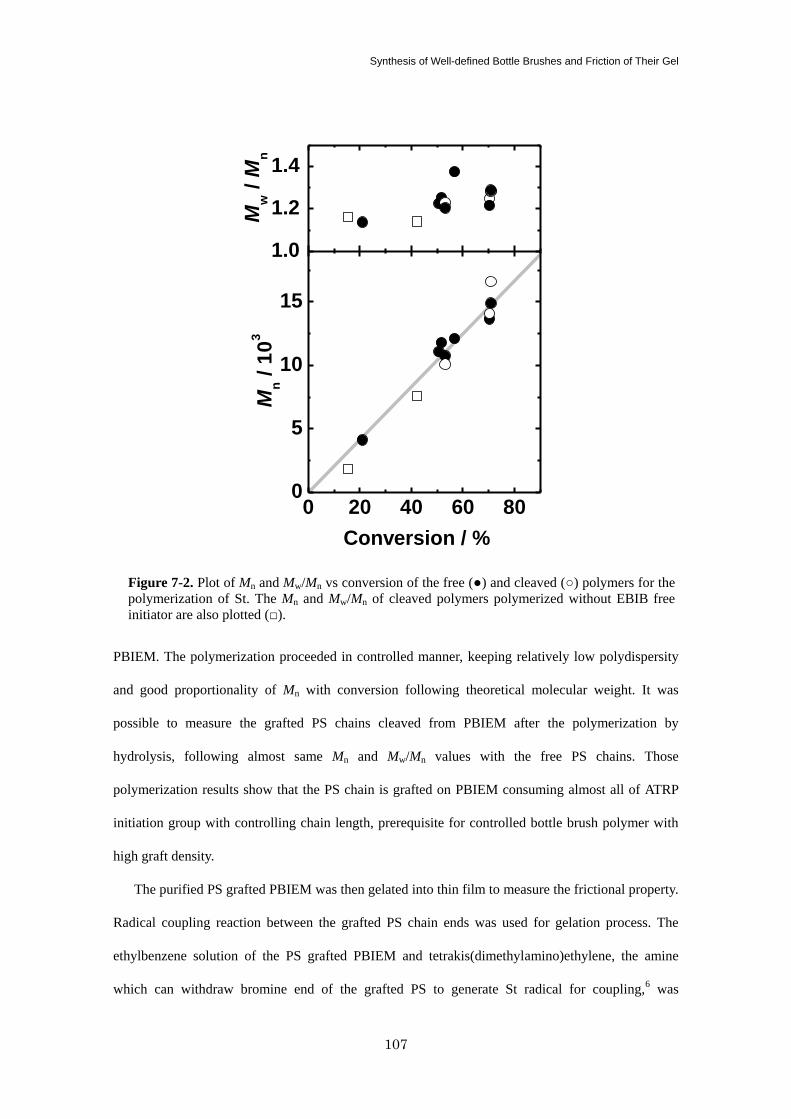
Synthesis of Well-defined Bottle Brushes and Friction of Their Gel
107
PBIEM. The polymerization proceeded in controlled manner, keeping relatively low polydispersity
and good proportionality of Mn with conversion following theoretical molecular weight. It was
possible to measure the grafted PS chains cleaved from PBIEM after the polymerization by
hydrolysis, following almost same Mn and Mw/Mn values with the free PS chains. Those
polymerization results show that the PS chain is grafted on PBIEM consuming almost all of ATRP
initiation group with controlling chain length, prerequisite for controlled bottle brush polymer with
high graft density.
The purified PS grafted PBIEM was then gelated into thin film to measure the frictional property.
Radical coupling reaction between the grafted PS chain ends was used for gelation process. The
ethylbenzene solution of the PS grafted PBIEM and tetrakis(dimethylamino)ethylene, the amine
which can withdraw bromine end of the grafted PS to generate St radical for coupling,6 was
0 20 40 60 800
5
10
15
Mw /
Mn
Mn /
10
3
Conversion / %
1.0
1.2
1.4
Figure 7-2. Plot of Mn and Mw/Mn vs conversion of the free (●) and cleaved (○) polymers for the
polymerization of St. The Mn and Mw/Mn of cleaved polymers polymerized without EBIB free
initiator are also plotted (□).
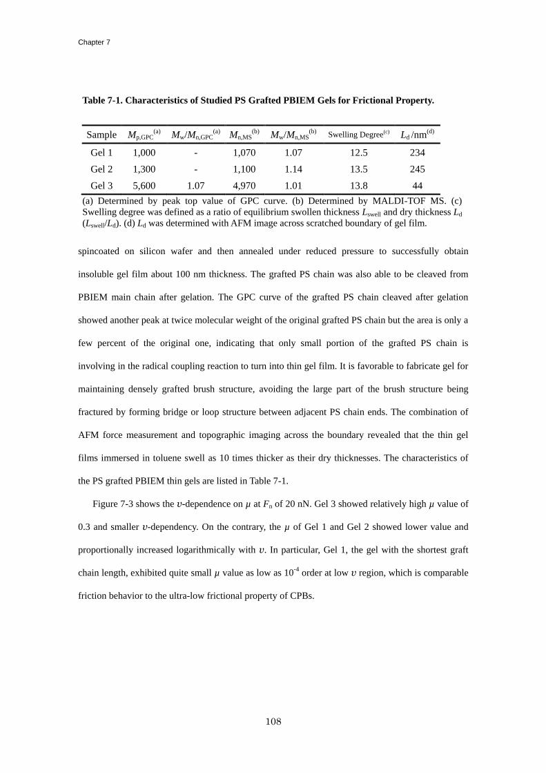
Chapter 7
108
spincoated on silicon wafer and then annealed under reduced pressure to successfully obtain
insoluble gel film about 100 nm thickness. The grafted PS chain was also able to be cleaved from
PBIEM main chain after gelation. The GPC curve of the grafted PS chain cleaved after gelation
showed another peak at twice molecular weight of the original grafted PS chain but the area is only a
few percent of the original one, indicating that only small portion of the grafted PS chain is
involving in the radical coupling reaction to turn into thin gel film. It is favorable to fabricate gel for
maintaining densely grafted brush structure, avoiding the large part of the brush structure being
fractured by forming bridge or loop structure between adjacent PS chain ends. The combination of
AFM force measurement and topographic imaging across the boundary revealed that the thin gel
films immersed in toluene swell as 10 times thicker as their dry thicknesses. The characteristics of
the PS grafted PBIEM thin gels are listed in Table 7-1.
Figure 7-3 shows the v-dependence on µ at Fn of 20 nN. Gel 3 showed relatively high µ value of
0.3 and smaller v-dependency. On the contrary, the µ of Gel 1 and Gel 2 showed lower value and
proportionally increased logarithmically with v. In particular, Gel 1, the gel with the shortest graft
chain length, exhibited quite small µ value as low as 10-4
order at low v region, which is comparable
friction behavior to the ultra-low frictional property of CPBs.
Table 7-1. Characteristics of Studied PS Grafted PBIEM Gels for Frictional Property.
Sample Mp,GPC(a) Mw/Mn,GPC
(a) Mn,MS(b) Mw/Mn,MS
(b) Swelling Degree(c) Ld /nm(d)
Gel 1 1,000 - 1,070 1.07 12.5 234
Gel 2 1,300 - 1,100 1.14 13.5 245
Gel 3 5,600 1.07 4,970 1.01 13.8 44
(a) Determined by peak top value of GPC curve. (b) Determined by MALDI-TOF MS. (c)
Swelling degree was defined as a ratio of equilibrium swollen thickness Lswell and dry thickness Ld
(Lswell/Ld). (d) Ld was determined with AFM image across scratched boundary of gel film.
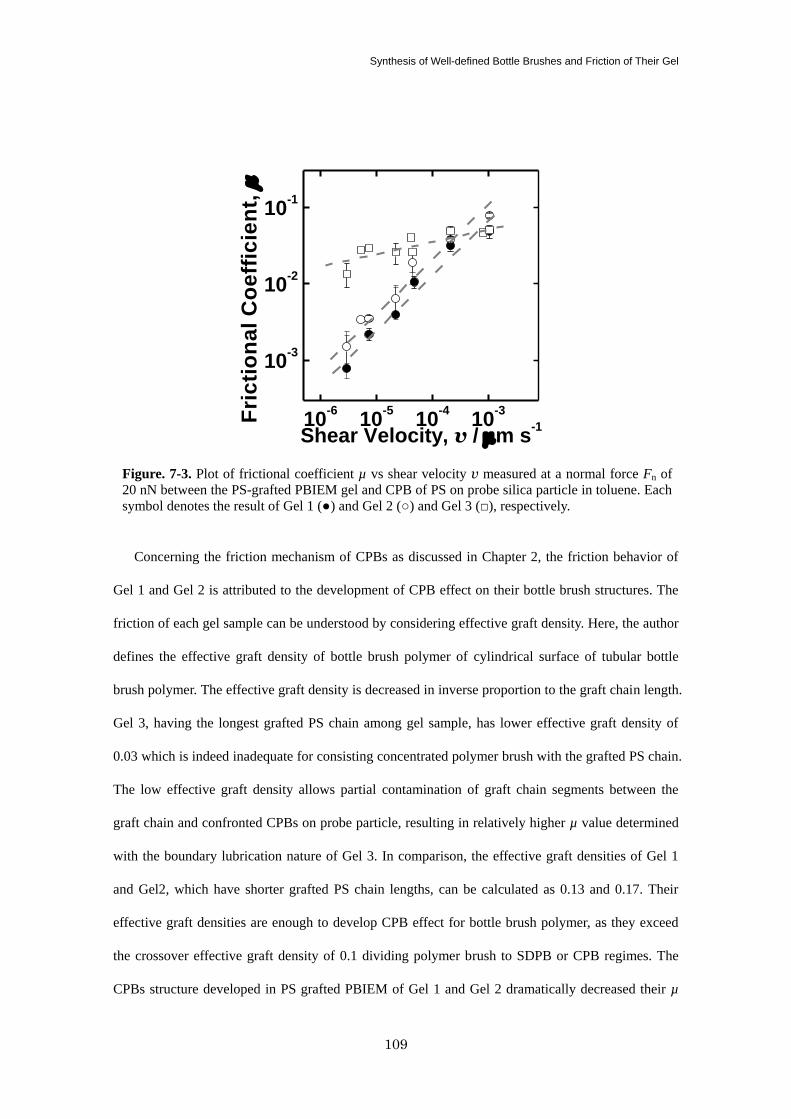
Synthesis of Well-defined Bottle Brushes and Friction of Their Gel
109
Concerning the friction mechanism of CPBs as discussed in Chapter 2, the friction behavior of
Gel 1 and Gel 2 is attributed to the development of CPB effect on their bottle brush structures. The
friction of each gel sample can be understood by considering effective graft density. Here, the author
defines the effective graft density of bottle brush polymer of cylindrical surface of tubular bottle
brush polymer. The effective graft density is decreased in inverse proportion to the graft chain length.
Gel 3, having the longest grafted PS chain among gel sample, has lower effective graft density of
0.03 which is indeed inadequate for consisting concentrated polymer brush with the grafted PS chain.
The low effective graft density allows partial contamination of graft chain segments between the
graft chain and confronted CPBs on probe particle, resulting in relatively higher µ value determined
with the boundary lubrication nature of Gel 3. In comparison, the effective graft densities of Gel 1
and Gel2, which have shorter grafted PS chain lengths, can be calculated as 0.13 and 0.17. Their
effective graft densities are enough to develop CPB effect for bottle brush polymer, as they exceed
the crossover effective graft density of 0.1 dividing polymer brush to SDPB or CPB regimes. The
CPBs structure developed in PS grafted PBIEM of Gel 1 and Gel 2 dramatically decreased their µ
10-6
10-5
10-4
10-3
10-3
10-2
10-1
Fri
cti
on
al
Co
eff
icie
nt,
m
Shear Velocity, v / mm s-1
Figure. 7-3. Plot of frictional coefficient µ vs shear velocity v measured at a normal force Fn of
20 nN between the PS-grafted PBIEM gel and CPB of PS on probe silica particle in toluene. Each
symbol denotes the result of Gel 1 (●) and Gel 2 (○) and Gel 3 (□), respectively.
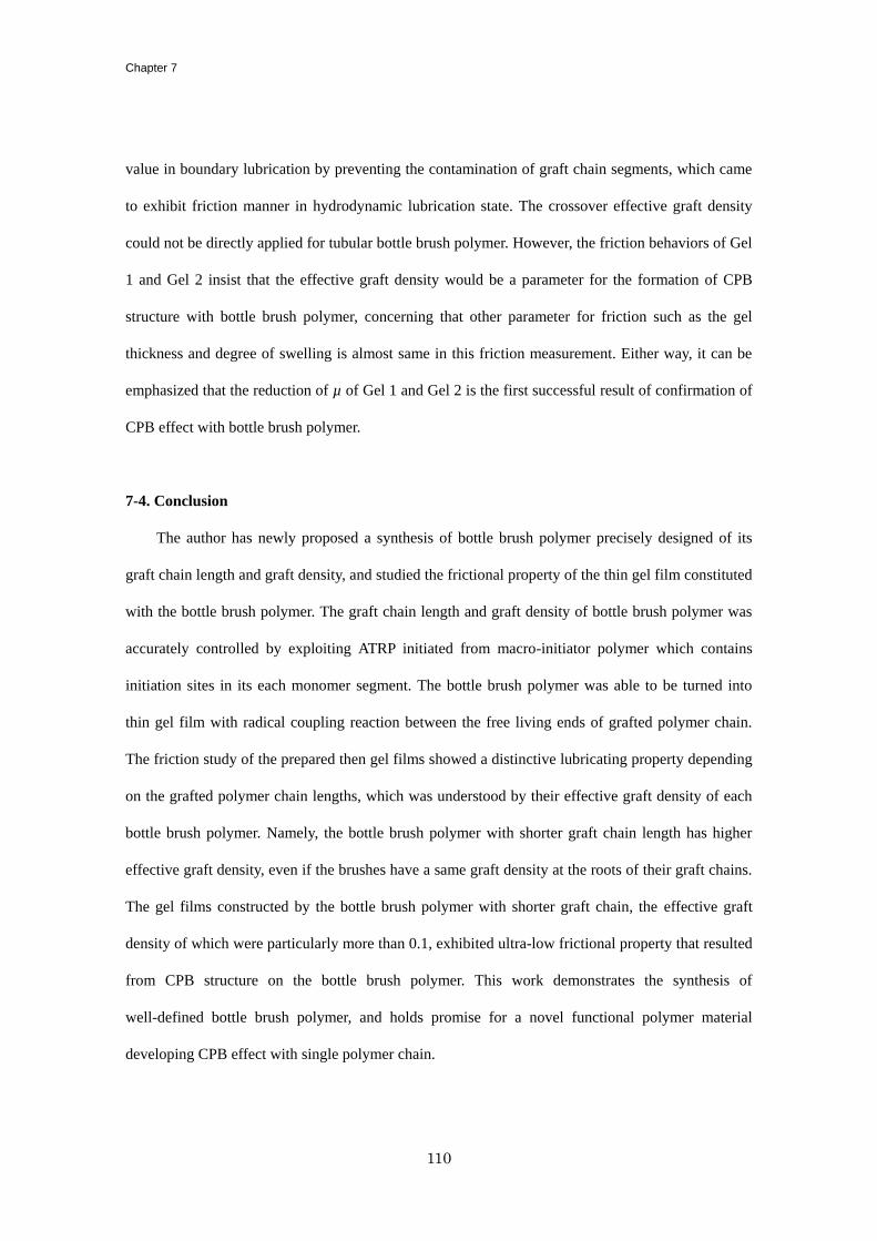
Chapter 7
110
value in boundary lubrication by preventing the contamination of graft chain segments, which came
to exhibit friction manner in hydrodynamic lubrication state. The crossover effective graft density
could not be directly applied for tubular bottle brush polymer. However, the friction behaviors of Gel
1 and Gel 2 insist that the effective graft density would be a parameter for the formation of CPB
structure with bottle brush polymer, concerning that other parameter for friction such as the gel
thickness and degree of swelling is almost same in this friction measurement. Either way, it can be
emphasized that the reduction of µ of Gel 1 and Gel 2 is the first successful result of confirmation of
CPB effect with bottle brush polymer.
7-4. Conclusion
The author has newly proposed a synthesis of bottle brush polymer precisely designed of its
graft chain length and graft density, and studied the frictional property of the thin gel film constituted
with the bottle brush polymer. The graft chain length and graft density of bottle brush polymer was
accurately controlled by exploiting ATRP initiated from macro-initiator polymer which contains
initiation sites in its each monomer segment. The bottle brush polymer was able to be turned into
thin gel film with radical coupling reaction between the free living ends of grafted polymer chain.
The friction study of the prepared then gel films showed a distinctive lubricating property depending
on the grafted polymer chain lengths, which was understood by their effective graft density of each
bottle brush polymer. Namely, the bottle brush polymer with shorter graft chain length has higher
effective graft density, even if the brushes have a same graft density at the roots of their graft chains.
The gel films constructed by the bottle brush polymer with shorter graft chain, the effective graft
density of which were particularly more than 0.1, exhibited ultra-low frictional property that resulted
from CPB structure on the bottle brush polymer. This work demonstrates the synthesis of
well-defined bottle brush polymer, and holds promise for a novel functional polymer material
developing CPB effect with single polymer chain.
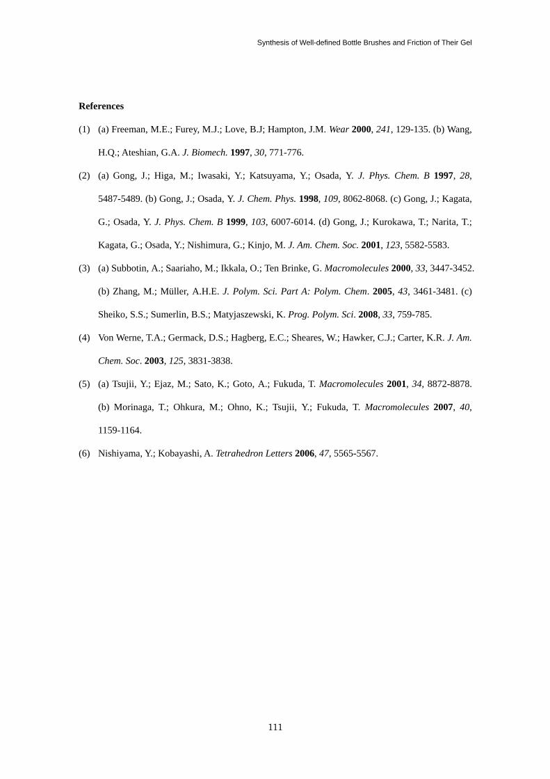
Synthesis of Well-defined Bottle Brushes and Friction of Their Gel
111
References
(1) (a) Freeman, M.E.; Furey, M.J.; Love, B.J; Hampton, J.M. Wear 2000, 241, 129-135. (b) Wang,
H.Q.; Ateshian, G.A. J. Biomech. 1997, 30, 771-776.
(2) (a) Gong, J.; Higa, M.; Iwasaki, Y.; Katsuyama, Y.; Osada, Y. J. Phys. Chem. B 1997, 28,
5487-5489. (b) Gong, J.; Osada, Y. J. Chem. Phys. 1998, 109, 8062-8068. (c) Gong, J.; Kagata,
G.; Osada, Y. J. Phys. Chem. B 1999, 103, 6007-6014. (d) Gong, J.; Kurokawa, T.; Narita, T.;
Kagata, G.; Osada, Y.; Nishimura, G.; Kinjo, M. J. Am. Chem. Soc. 2001, 123, 5582-5583.
(3) (a) Subbotin, A.; Saariaho, M.; Ikkala, O.; Ten Brinke, G. Macromolecules 2000, 33, 3447-3452.
(b) Zhang, M.; Müller, A.H.E. J. Polym. Sci. Part A: Polym. Chem. 2005, 43, 3461-3481. (c)
Sheiko, S.S.; Sumerlin, B.S.; Matyjaszewski, K. Prog. Polym. Sci. 2008, 33, 759-785.
(4) Von Werne, T.A.; Germack, D.S.; Hagberg, E.C.; Sheares, W.; Hawker, C.J.; Carter, K.R. J. Am.
Chem. Soc. 2003, 125, 3831-3838.
(5) (a) Tsujii, Y.; Ejaz, M.; Sato, K.; Goto, A.; Fukuda, T. Macromolecules 2001, 34, 8872-8878.
(b) Morinaga, T.; Ohkura, M.; Ohno, K.; Tsujii, Y.; Fukuda, T. Macromolecules 2007, 40,
1159-1164.
(6) Nishiyama, Y.; Kobayashi, A. Tetrahedron Letters 2006, 47, 5565-5567.

Chapter 7
112
113
Summary
In Chapter 1, the background, purpose, and outline of this thesis were described.
In Chapter 2, the effect of solvent quality and hence degree of swelling on the frictional
property of CPBs was investigated using the polystyrene (PS) brush samples. The degree of swelling
of the brush was successfully controlled by varying the solvent composition of toluene/2-propanol
mixture. The data of frictional coefficient µ as a function of shear velocity v and solvent composition
(and hence degree of swelling) were well understood by two mechanisms of lubrication, boundary
and hydrodynamic lubrications. At low v in toluene-rich solvents, the boundary lubrication
mechanism afforded µ values less dependent on v and exceptionally small on the order of 10-4
, as
had previously been observed for the CPB of poly (methyl methacrylate) (PMMA) in toluene and
ascribed to effective suppression of interpenetration between polymer brushes. This study more
focused on the hydrodynamic lubrication regime observed in a wide range of solvent compositions.
The µ data in this regime were well described by the relationship µ = β∙vα, where the parameter α
was almost constant and close to unity and the parameter β was scaled by the degree of swelling,
suggesting that the viscosity resistance on and in the solvent-swollen polymer brush dominated the
friction.
In Chapter 3, the frictional property of the CPB of PMMA was investigated in highly viscous
ionic liquids (ILs) (DEME-TFSI and EMI-TFSI) and toluene. These ILs could swell the CPB of
PMMA to the same degree as toluene, a more commonly used good solvent of much lower viscosity.
As expected between the concentrated polymer brushes in good solvents, little adhesive interaction
in the ILs was observed, decreasing the µ in the boundary lubrication regime to values presumably
on the order of 10-4
, as was the case in toluene. This allowed the hydrodynamic lubrication
mechanism to dominate the friction. In this regime, the v dependence of µ followed the
above-mentioned power-law scaling with an α value close to unity. Interestingly, the β parameter
was simply scaled by the viscosity of solvent even though the viscosity differed by nearly two orders
Summary
114
of magnitude. The study did not only clarify the nature of hydrodynamic lubrication but also
suggested the ability, as an excellent-lubrication system, of the CPB combined with IL.
In Chapter 4, the frictional property between the CPBs of immiscible polymers, PS and
PMMA, was investigated in toluene, a good solvent for both polymers, to clarify the feature in the
boundary lubrication of the CPB system. The immiscibility was demonstrated to effectively lower
the frictional coefficient, approximately by half, to a value on the order of 10-5
. This means that in a
good solvent, the confronted CPBs of the identical polymer partly interpenetrate each other at the
outermost surface by compression and that this interaction determines the friction in the boundary
lubrication (on the order of 10-4
in µ).
In Chapter 5, the CPBs of water-soluble polymers, poly (2-hydroxyethyl acrylate) (PHEA) and
poly (poly(oxyethyleneglycol)methylether acrylate) (PPEGA), were newly synthesized by applying
photo-induced TERP to surface-initiated graft polymerization, where TERP refers to the
organotellurium-mediated radical polymerization, and their swelling and frictional properties in
water media were investigated. In water, the CPBs of PHEA and PPEGA had equilibrium
thicknesses of ca. 50% and 120%, respectively, against the weight-average contour length of graft
chains. This indicates that water is a reasonably good solvent for PPEGA but not for PHEA. The
frictional property of these brushes was well understood by the above-mentioned boundary and
hydrodynamic lubrications. Reflecting less quality as a solvent, the PHEA brush showed a higher
value of µ in the boundary lubrication, consistent with the fact that adhesive interaction was
observed for this system. More interestingly, the CPB of PPEGA gave a µ value on the order of 10-4
in pure water as well as in 0.1 M NaCl aqueous solution. Such super lubrication was concluded to be
common to the CPBs, e.g., even in an aqueous system.
In Chapter 6, the CPB and semi-dilute polymer brush (SDPB) of poly (N-isopropyl
acrylamide) (PNIPAM) were synthesized via surface-initiated ATRP, and their swelling and
frictional properties in water were investigated as a function of temperature. Temperature-induced
swelling/shrinking process was observed for both the CPB and SDPB, the former of which had a
Summary
115
more gradual change owing to its highly stretched chain conformation. At low temperatures, the
CPB achieved µ values lower than 4 × 10⁻⁴
, nearly three orders of magnitude lower than those of the
SDPB. More notably for the CPB, a sharp transition in µ was triggered by temperature at around 30
oC, namely, the µ value changed by more than three orders of magnitude in a narrow temperature
span, unlike the SDPB. Such stimulus-responsive water lubrication is of importance in developing
novel and advanced applications in technological and biomedical fields.
In Chapter 7, the bottle brushes of PS-side chains were synthesized, and the frictional property
of thin gel films of these bottle brushes was investigated. The ATRP from a multi-initiator, poly
(2-(2-bromo-2-methylpropanoyloxy)ethyl methacrylate) (PBIEM), proceeded with almost complete
initiation, giving the bottle brushes with controlled side-chain lengths. Using an amine catalyst,
effective radical coupling between side-chain ends was successfully achieved, processing the bottle
brushes into thin gel films. Thus prepared films were swollen in toluene, a good solvent for PS, and
the µ value on their surfaces was measured against the CPB of PS. Interestingly, the samples of
sufficiently short side-chains were much improved in lubrication; the µ value was dependent of v,
going down to the order of 10-4
in a low v range (almost comparable to the value between the CPBs
of PS in toluene). This result was discussed on the basis of the crossover density between the SDPB
and CPB by assuming the swollen bottle brush as a column with a radius equal to the fully stretched
side-chain length.
Through the thesis, the author revealed the lubrication mechanism of CPBs in solvents and
thereby developed new types of lubricating surfaces. The features of lubrication for the CPB are
summarized as follows; (i) the boundary lubrication is much improved on the order of 10-4
or
sometimes 10-5
in µ, allowing the hydrodynamic lubrication, and (ii) the hydrodynamic lubrication is
well understood by the local viscosity affected by the degree of swelling of the brush and the
viscosity of solvent. The author hopes that these fundamental studies shed new light on the science
of tribology, leading to new design for sophisticated and intelligent tribomaterials.

Summary
116
117
List of Publication
Chapter 2.
(1) Lubrication Mechanism of Concentrated Polymer Brushes in Solvents: Effect of Solvent
Quality and Thereby Swelling State
Nomura, A.; Okayasu, K.; Ohno, K.; Fukuda, T.; Tsujii, Y. Macromolecules 2011, 44,
5013-5019.
Chapter 3.
(2) Lubrication Mechanism of Concentrated Polymer Brushes in Solvents: Effect of Solvent
Viscosity
Nomura, A.; Okayasu, K.; Ohno, K.; Fukuda, T.; Sato, T.; Tsujii, Y. Polym. Chem. submitted.
Chapter 4.
(3) Super Lubrication and its Mechanism between Immiscible Concentrated Polymer Brushes in
Good Solvent
Nomura, A.; Okayasu, K.; Ohno, K.; Fukuda, T.; Tsujii, Y. Macromolecules to be submitted.
Chapter 5.
(4) Controlled Synthesis of Hydrophilic Concentrated Polymer Brushes and Their
Friction/Lubrication Properties in Aqueous Solutions
Nomura, A.; Goto, A.; Tsujii, Y.; Kayahara, E.; Yamago, S. J. Polym. Sci., Part A: Polym.
Chem. submitted.
Chapter 6.
(5) Thermoresponsive Water Lubrication by Concentrated Polymer Brushes
List of Publications
118
Gao, W.; Nomura, A.; Ohno, K.; Tsujii, Y.; Fukuda, T. Macromolecules submitted.
Chapter 7.
(6) Synthesis and Frictional Property of Graft-Type Gel with Concentrated Polymer Brush
Structure
Nomura, A.; Nakahara, R.; Ohno, K.; Tsujii, Y. Adv. Mat. to be submitted.
Other Associated Publications.
(7) AFM Studies on Microtribology of Concentrated Polymer Brushes in Solvents
Tsujii, Y.; Nomura, A.; Okayasu, K.; Gao, W.; Ohno, K.; Fukuda, T. J. Phys.: Conference
Series 2009, 184, 012031.
(8) Use of Alcohol as Initiator for Reversible Chain Transfer Catalyzed Polymerization
Kim, J.; Nomura, A.; Fukuda, T.; Goto, A.; Tsujii, Y. Macromol. React. Eng. 2010, 4, 272-277.
(9) Super Lubrication of Concentrated Polymer Brushes in Good Solvent
Tsujii, Y.; Okayasu, K.; Nomura, A.; Ohno, K.; Fukuda, T. Polymer submitted.
(10) Synthesis and Characterization of Polystyrene Brushes Using a Surface-initiated Atom Transfer
Radical Polymerization for Organic Thin Film Transistors
Hwang, D. -H.; Nomura, A.; Kim, J.; Cho, H.; Lee, C.; Ohno, K.; Tsujii, Y. J. Nanosci.
Nanotech. 2011, in Press.
119
Acknowledgements
The present investigations were carried out at the Institute for Chemical Research, Kyoto
University in the period from 2006 to 2011.
The author would like to express his sincere gratitude to Professor Yoshinobu Tsujii for his
invaluable guidance, stimulating discussions and encouragement throughout this work.
Grateful acknowledgement is due to Emeritus Professor Takeshi Fukuda, Associate Professor
Kohji Ohno and Associate Professor Atushi Goto for his enthusiastic guidance, valuable discussion
and encouragement.
The author wishes to express his appreciation to Professor Takaya Sato, Professor Shigeru
Yamago and Dr. Eiichi Kayahara for their useful suggestions.
Sincere appreciation is due to all of his colleagues in Professor Tsujii’s Labolatory for their kind
helps, particulary, to Dr. Weiping Gao, Dr. Jeongsik Kim, Mr. Kenji Okayasu and Mr. Ryo Nakahara
for their active collaborations in part of the study.
Finally, the author wishes to express his heartfelt thanks to his parents, Ritsuo Nomura and
Hiroko Nomura, and his brother Masahiro Nomura, for their devoted support, and to his wife, Akiko
Nomura for her heartfelt encouragement.
May, 2011
Akihiro Nomura
![[chapter] [chapter] IUT INFO 1 / 2012-2013 atiques pdf/Poly_Alg_Ana... · [chapter] [chapter] atiques IUT INFO 1 / 2012-2013 Licence Creative Commons MAJ: 17 mars 2013 Mathématiques](https://img.pdfslide.fr/doc/110x75/5b99c5b309d3f29c338ce956/chapter-chapter-iut-info-1-2012-2013-atiques-pdfpolyalgana-chapter.jpg)


![DUT INFO / 1 année / 2014 - 2015 [chapter] [chapter] THique pdf... · 2014. 12. 16. · THique [chapter] [chapter] DUT INFO / 1ère année / 2014 - 2015 Licence Creative Commons](https://img.pdfslide.fr/doc/110x75/60b3e0ca968cc34b2256c821/dut-info-1-anne-2014-2015-chapter-chapter-thique-pdf-2014-12.jpg)


![[chapter] [chapter] atiques](https://img.pdfslide.fr/doc/110x75/62ab0da599df7d685a5c7171/chapter-chapter-atiques.jpg)