Embed Size (px)
Citation preview
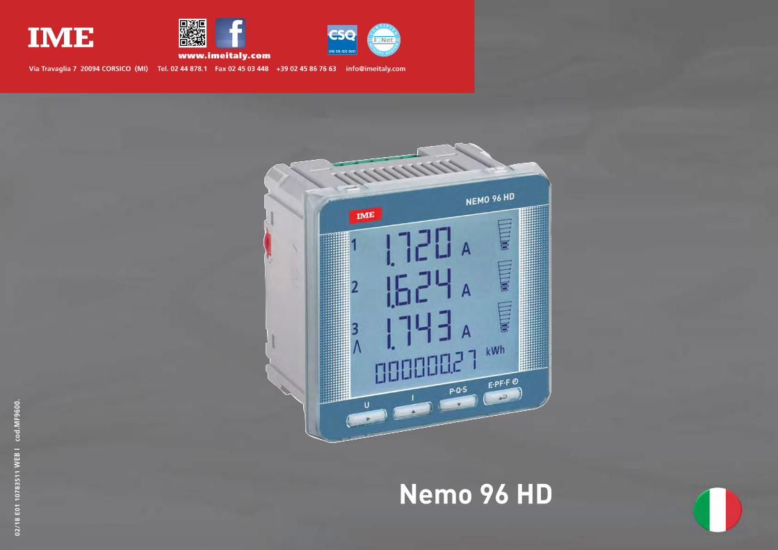
Nemo 96 HD
Via Travaglia 7 20094 CORSICO (MI) Tel. 02 44 878.1 Fax 02 45 03 448 +39 02 45 86 76 63 [email protected]
www.imeitaly.com
02/18 E01 10783511WEB
I cod.M
F960
0.
02/18 E01 107835110 WEB I cod.MF9600.2
Nemo 96 HD
MultimisuraMisuranoe visualizzanopiù grandezzecontemporaneamente
ConteggioenergiaQuantificanoi consumi energetici
ComunicazioneComunicano le misureeffettuate a distanzaInterfacciano differentimodi di comunicazione
Misurae controlloMisuranoe intervengonosegnalando condizioniparticolari
IndiceSchemi d’inserzione pag.3
Istruzioni per l’installazione pag.3
Programmazione pag.4-5
Diagnostica sequenza fasipag.5
Livello 1 Password 1000 pag.6-9
Livello 2 Password 2001 pag.10
Livello 3 Password 3002 pag.19
Visualizzazione pag.11Reset pag.11
Trifase 4 fili pag.12-13
Trifase 3 fili pag.14-15
Monofase pag.16-17
Alimentazione Ausiliaria pag.18
Moduli opzionali pag.18
Inserimento moduli opzionali pag.19
Impostazione di fabbrica pag.20
La documentazione tecnica del prodotto è disponibile sul sito www.imeitaly.com nell’area “Documentazione tecnica” digitare nel campo “Codice Nota Tecnica: NT680”.
La I.M
.E. S
.p.A.
si ris
erva i
n qua
lsias
i mom
ento,
di m
odific
are le
carat
terist
iche t
ecnic
he se
nza d
arne p
reavv
iso.
02/18 E01 10783511 WEB I cod.MF9600. 3
Nemo 96 HD
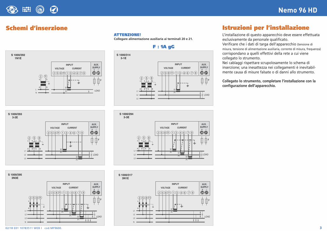
ATTENZIONE!Collegare alimentazione ausiliaria ai terminali 20 e 21.
Schemi d’inserzione
X
XX
S1
P1
S1
P1
a
A
b
B
a
A
b
BL1
L2
L3
LOAD
2 5 8
INPUT
VOLTAGE CURRENT
20
AUX.SUPPLY
21+ –
2 5 8 1 3 6 94 711
F
2 5 8 111 3 6 94 7
S1
P1
a
A
b
BL
NLOADX
20
AUX.SUPPLY
2121+ –
2 11
INPUT
VOLTAGE CURRENT
F
X
XX
S1
P1 S1
P1 S1
P1
a
A
b
B
a
A
b
BL1
L2
L3
LOAD
2 5 8
INPUT
VOLTAGE CURRENT
20
AUX.SUPPLY
21+ –
2 5 8 1 3 6 94 711
F
S 1000/2921N1E
S 1000/2933-2E
S 1000/2943-3E
X
XX
S1
P1
a
A
b
B
a
A
b
BL1
L2
L3
LOAD
2 5 8
INPUT
VOLTAGE CURRENT
20
AUX.SUPPLY
21+ –
2 5 8 1 3 6 94 711
F
S 1000/3143-1E
F : 1A gG
X
XX
S1
P1 S1
P1 S1
P1
a
AL1
L2
L3
NX X X
LOAD
INPUT
VOLTAGE CURRENT
20
AUX.SUPPLY
21+ –
2 5 8 1 3 6 94 711
2 5 8 11F
S 1000/2953N3E
X
XX
S1
P1
a
A
X X X
LOAD
INPUT
VOLTAGE CURRENT
20
AUX.SUPPLY
2121+ –
2 5 8 1 3 6 94 711
2 5 8 11
L1
L2
L3
N
F
S 1000/3173N1E
Istruzioni per l’installazioneL’installazione di questo apparecchio deve essere effettuataesclusivamente da personale qualificato.Verificare che i dati di targa dell’apparecchio (tensione dimisura, tensione di alimentazione ausiliaria, corrente di misura, frequenza)
corrispondano a quelli effettivi della rete a cui vienecollegato lo strumento.Nei cablaggi rispettare scrupolosamente lo schema diinserzione; una inesattezza nei collegamenti è inevitabil-mente causa di misure falsate o di danni allo strumento.
Collegato lo strumento, completare l’installazione con laconfigurazione dell’apparecchio.
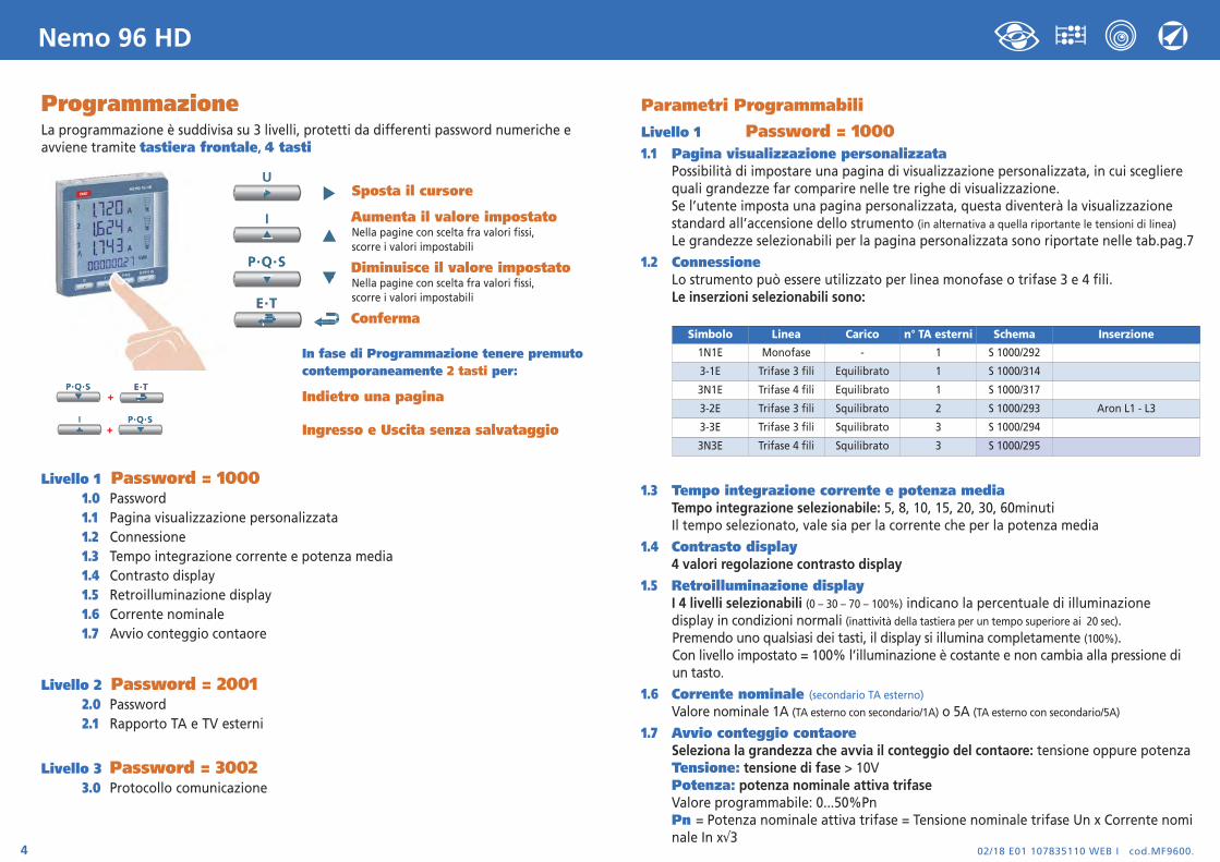
ProgrammazioneLa programmazione è suddivisa su 3 livelli, protetti da differenti password numeriche eavviene tramite tastiera frontale, 4 tasti
Sposta il cursore
Aumenta il valore impostatoNella pagine con scelta fra valori fissi, scorre i valori impostabili
Diminuisce il valore impostatoNella pagine con scelta fra valori fissi, scorre i valori impostabili
Conferma
In fase di Programmazione tenere premutocontemporaneamente 2 tasti per:
Indietro una pagina
Ingresso e Uscita senza salvataggio
Livello 1 Password = 10001.0 Password1.1 Pagina visualizzazione personalizzata1.2 Connessione1.3 Tempo integrazione corrente e potenza media1.4 Contrasto display1.5 Retroilluminazione display1.6 Corrente nominale1.7 Avvio conteggio contaore
Livello 2 Password = 20012.0 Password2.1 Rapporto TA e TV esterni
Livello 3 Password = 30023.0 Protocollo comunicazione
02/18 E01 107835110 WEB I cod.MF9600.4
Nemo 96 HD
Parametri Programmabili
Livello 1 Password = 10001.1 Pagina visualizzazione personalizzata
Possibilità di impostare una pagina di visualizzazione personalizzata, in cui scegliere quali grandezze far comparire nelle tre righe di visualizzazione.Se l’utente imposta una pagina personalizzata, questa diventerà la visualizzazionestandard all’accensione dello strumento (in alternativa a quella riportante le tensioni di linea)Le grandezze selezionabili per la pagina personalizzata sono riportate nelle tab.pag.7
1.2 ConnessioneLo strumento può essere utilizzato per linea monofase o trifase 3 e 4 fili.Le inserzioni selezionabili sono:
1.3 Tempo integrazione corrente e potenza mediaTempo integrazione selezionabile: 5, 8, 10, 15, 20, 30, 60minutiIl tempo selezionato, vale sia per la corrente che per la potenza media
1.4 Contrasto display4 valori regolazione contrasto display
1.5 Retroilluminazione displayI 4 livelli selezionabili (0 – 30 – 70 – 100%) indicano la percentuale di illuminazione display in condizioni normali (inattività della tastiera per un tempo superiore ai 20 sec).Premendo uno qualsiasi dei tasti, il display si illumina completamente (100%).Con livello impostato = 100% l’illuminazione è costante e non cambia alla pressione di un tasto.
1.6 Corrente nominale (secondario TA esterno)Valore nominale 1A (TA esterno con secondario/1A) o 5A (TA esterno con secondario/5A)
1.7 Avvio conteggio contaoreSeleziona la grandezza che avvia il conteggio del contaore: tensione oppure potenza Tensione: tensione di fase > 10VPotenza: potenza nominale attiva trifaseValore programmabile: 0...50%PnPn = Potenza nominale attiva trifase = Tensione nominale trifase Un x Corrente nominale In x√3
Simbolo Linea Carico n° TA esterni Schema Inserzione
1N1E Monofase - 1 S 1000/292
3-1E Trifase 3 fili Equilibrato 1 S 1000/314
3N1E Trifase 4 fili Equilibrato 1 S 1000/317
3-2E Trifase 3 fili Squilibrato 2 S 1000/293 Aron L1 - L3
3-3E Trifase 3 fili Squilibrato 3 S 1000/294
3N3E Trifase 4 fili Squilibrato 3 S 1000/295
02/18 E01 10783511 WEB I cod.MF9600. 5
Nemo 96 HD
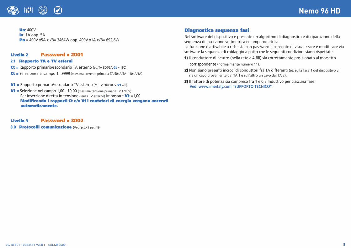
Un: 400VIn: 1A opp. 5APn = 400V x5A x √3= 3464W opp. 400V x1A x√3= 692,8W
Livello 2 Password = 20012.1 Rapporto TA e TV esterniCt = Rapporto primario/secondario TA esterno (es. TA 800/5A Ct = 160)
Ct = Selezione nel campo 1...9999 (massima corrente primaria TA 50kA/5A – 10kA/1A)
Vt = Rapporto primario/secondario TV esterno (es. TV 600/100V Vt = 6)
Vt = Selezione nel campo 1,00...10,00 (massima tensione primaria TV 1200V)
Per inserzione diretta in tensione (senza TV esterno) impostare Vt =1,00Modificando i rapporti Ct e/o Vt i contatori di energia vengono azzerati automaticamente.
Livello 3 Password = 30023.0 Protocolli comunicazione (Vedi p.to 3 pag.19)
Diagnostica sequenza fasiNel software del dispositivo è presente un algoritmo di diagnostica e di riparazione dellasequenza di inserzione voltmetrica ed amperometrica.La funzione è attivabile a richiesta con password e consente di visualizzare e modificare viasoftware la sequenza di cablaggio a patto che le seguenti condizioni siano rispettate:
1) Il conduttore di neutro (nella rete a 4 fili) sia correttamente posizionato al morsetto
corrispondente (normalmente numero 11).
2) Non siano presenti incroci di conduttori fra TA differenti (es. sulla fase 1 del dispositivo vi sia un cavo proveniente dal TA 1 e sull’altro un cavo dal TA 2).
3) Il fattore di potenza sia compreso fra 1 e 0,5 Induttivo per ciascuna fase.Vedi www.imeitaly.com “SUPPORTO TECNICO”.
02/18 E01 107835110 WEB I cod.MF9600.6
Nemo 96 HD
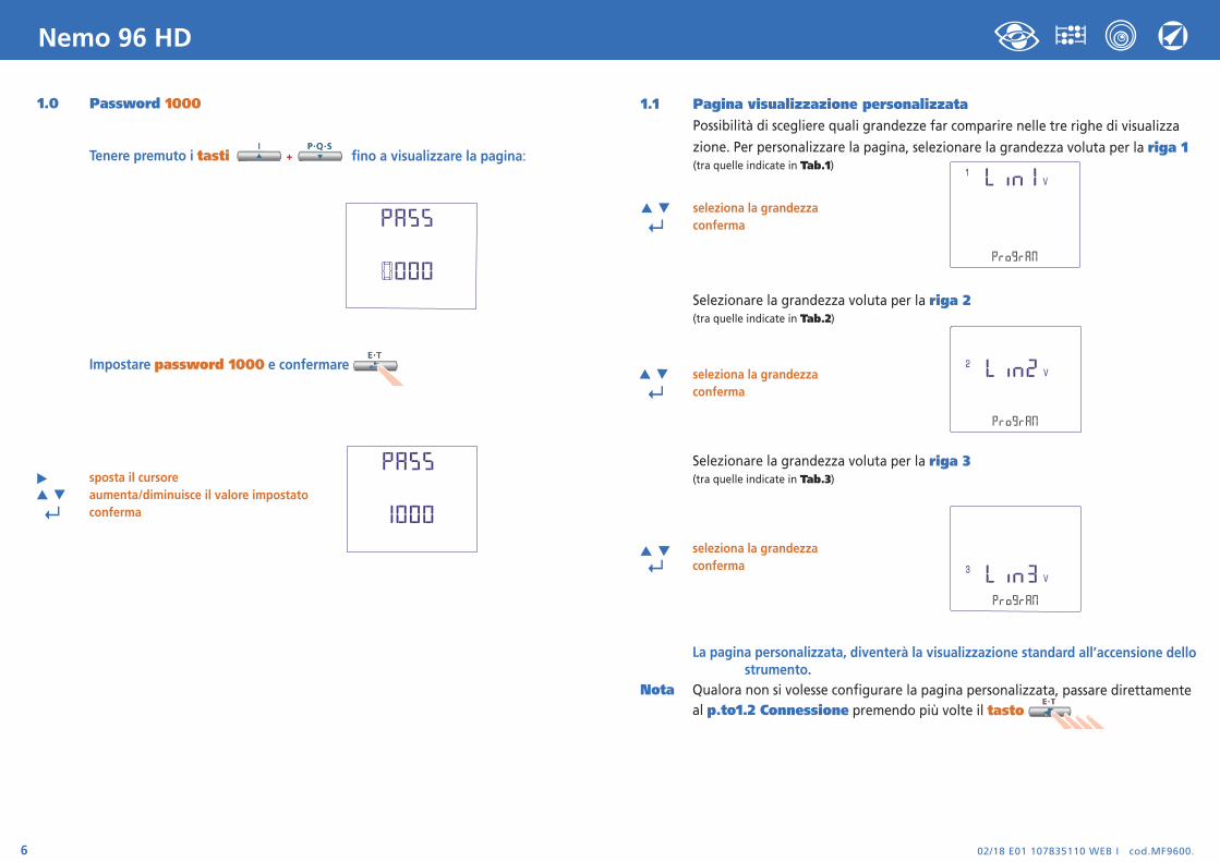
1.0 Password 1000
Tenere premuto i tasti fino a visualizzare la pagina:
Impostare password 1000 e confermare
sposta il cursoreaumenta/diminuisce il valore impostato
↵ conferma
1.1 Pagina visualizzazione personalizzataPossibilità di scegliere quali grandezze far comparire nelle tre righe di visualizza
zione. Per personalizzare la pagina, selezionare la grandezza voluta per la riga 1(tra quelle indicate in Tab.1)
seleziona la grandezza
↵ conferma
Selezionare la grandezza voluta per la riga 2(tra quelle indicate in Tab.2)
seleziona la grandezza
↵ conferma
Selezionare la grandezza voluta per la riga 3(tra quelle indicate in Tab.3)
seleziona la grandezza
↵ conferma
La pagina personalizzata, diventerà la visualizzazione standard all’accensione dellostrumento.
Nota Qualora non si volesse configurare la pagina personalizzata, passare direttamente al p.to1.2 Connessione premendo più volte il tasto

02/18 E01 10783511 WEB I cod.MF9600. 7
Nemo 96 HD
Riga 1 Tab.1Tensione L1
Tensione L2
Riga 2 Tab.2 Riga 3 Tab.3
Tensione L3
Tensione L1-L2
Corrente L1
Potenza Attiva Trifase
Potenza Reattiva Trifase
Potenza Apparente Trifase
Potenza Attiva L1
Potenza Reattiva L1
Potenza Apparente L1
Fattore di Potenza Trifase
Tensione L2-L3
Corrente L2
Potenza Attiva Trifase
Potenza Reattiva Trifase
Potenza Apparente Trifase
Potenza Attiva L2
Potenza Reattiva L2
Potenza Apparente L2
Frequenza
Corrente L1
Tensione L3-L1
Corrente L3
Potenza Attiva Trifase
Potenza Reattiva Trifase
Potenza Apparente Trifase
Potenza Attiva L3
Potenza Reattiva L3
Potenza Apparente L3
Potenza Attiva L1
Corrente L1
Corrente di Neutro

02/18 E01 107835110 WEB I cod.MF9600.8
Nemo 96 HD
1.2 Connessione
seleziona la connessione
↵ conferma
Selezionare il tipo di inserzione desiderato, rispettando poi scrupolosamente lo schema di collegamento abbinato. Le inserzioni selezionabili sono:
1.3 Tempo integrazione corrente e potenza mediaTempo integrazione selezionabile: 5, 8, 10, 15, 20, 30, 60minutiIl tempo selezionato, vale sia per la corrente che per la potenza media
seleziona il valore di tempo
↵ conferma
1.4 Contrasto display4 valori di regolazione contrasto display
seleziona il livello di contrasto
↵ conferma
1.5 Illuminazione displayI 4 livelli selezionabili (0 – 30 – 70 – 100%) indicano la percentuale di illuminazione display
seleziona il livello di illuminazione
↵ conferma
1.6 Corrente nominale (secondario TA esterno)Valore nominale 1A (TA esterno con secondario /1A) o 5A (TA esterno con secondario /5A)
seleziona 1A o 5A
↵ conferma
Simbolo Linea Carico n° TA esterni Schema Inserzione
1N1E Monofase - 1 S 1000/292
3-1E Trifase 3 fili Equilibrato 1 S 1000/314
3N1E Trifase 4 fili Equilibrato 1 S 1000/317
3-2E Trifase 3 fili Squilibrato 2 S 1000/293 Aron L1 - L3
3-3E Trifase 3 fili Squilibrato 3 S 1000/294
3N3E Trifase 4 fili Squilibrato 3 S 1000/295
02/18 E01 10783511 WEB I cod.MF9600. 9
Nemo 96 HD
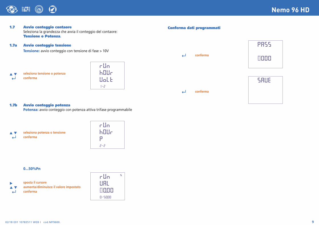
Conferma dati programmati
↵ conferma
↵ conferma
1.7 Avvio conteggio contaoreSeleziona la grandezza che avvia il conteggio del contaore:Tensione o Potenza.
1.7a Avvio conteggio tensioneTensione: avvio conteggio con tensione di fase > 10V
seleziona tensione o potenza
↵ conferma
1.7b Avvio conteggio potenzaPotenza: avvio conteggio con potenza attiva trifase programmabile
seleziona potenza o tensione ↵ conferma
0...50%Pn
sposta il cursore aumenta/diminuisce il valore impostato ↵ conferma
02/18 E01 107835110 WEB I cod.MF9600.10
Nemo 96 HD
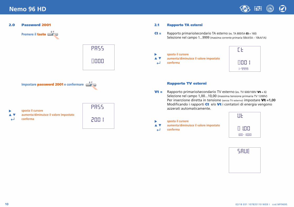
2.0 Password 2001
Premere il tasto
Impostare password 2001 e confermare
sposta il cursoreaumenta/diminuisce il valore impostato
↵ conferma
2.1 Rapporto TA esterni
Ct = Rapporto primario/secondario TA esterno (es. TA 800/5A Ct = 160)Selezione nel campo 1...9999 (massima corrente primaria 50kA/5A – 10kA/1A)
sposta il cursore aumenta/diminuisce il valore impostato ↵ conferma
Rapporto TV esterni
Vt = Rapporto primario/secondario TV esterno (es. TV 600/100V Vt = 6)
Selezione nel campo 1,00...10,00 (massima tensione primaria TV 1200V)
Per inserzione diretta in tensione (senza TV esterno) impostare Vt =1,00Modificando i rapporti Ct e/o Vt i contatori di energia vengonoazzerati automaticamente.
sposta il cursore aumenta/diminuisce il valore impostato ↵ conferma
02/18 E01 10783511 WEB I cod.MF9600. 11
Nemo 96 HD
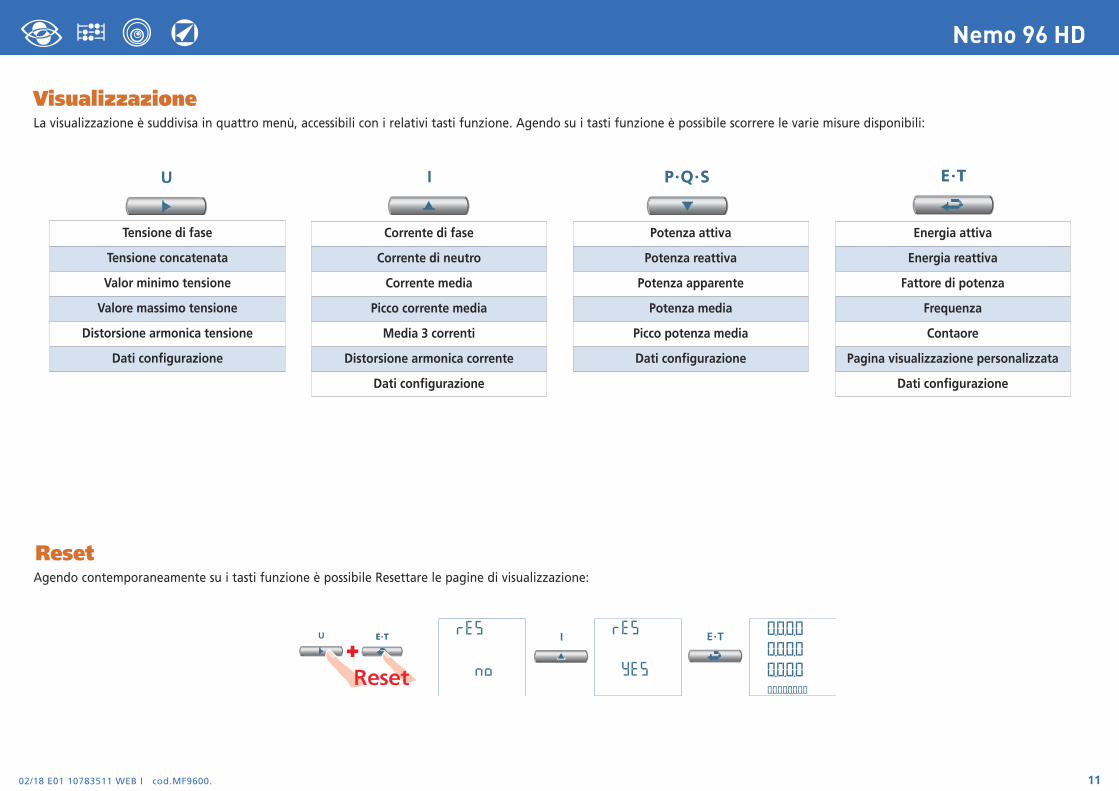
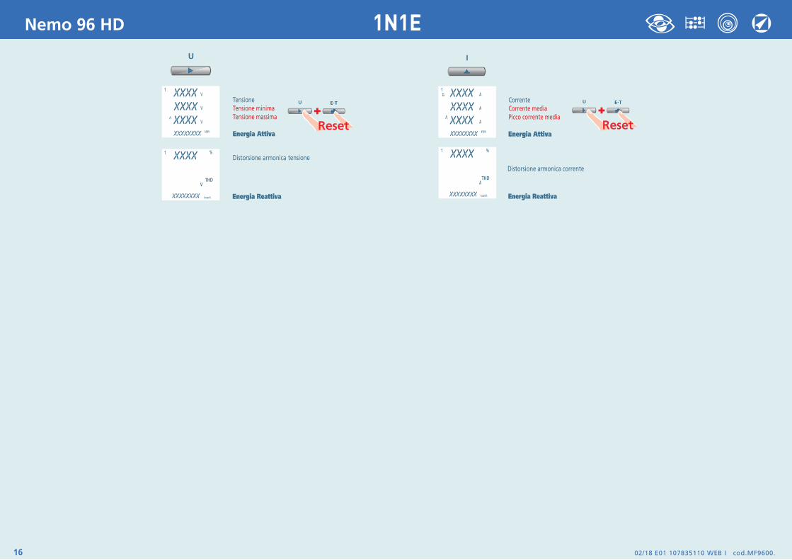
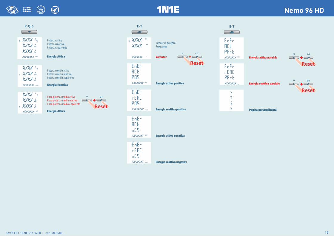
VisualizzazioneLa visualizzazione è suddivisa in quattro menù, accessibili con i relativi tasti funzione. Agendo su i tasti funzione è possibile scorrere le varie misure disponibili:
ResetAgendo contemporaneamente su i tasti funzione è possibile Resettare le pagine di visualizzazione:
Tensione di fase
Tensione concatenata
Valor minimo tensione
Valore massimo tensione
Distorsione armonica tensione
Dati configurazione
Corrente di fase
Corrente di neutro
Corrente media
Picco corrente media
Media 3 correnti
Distorsione armonica corrente
Dati configurazione
Potenza attiva
Potenza reattiva
Potenza apparente
Potenza media
Picco potenza media
Dati configurazione
Energia attiva
Energia reattiva
Fattore di potenza
Frequenza
Contaore
Pagina visualizzazione personalizzata
Dati configurazione
+
02/18 E01 107835110 WEB I cod.MF9600.12
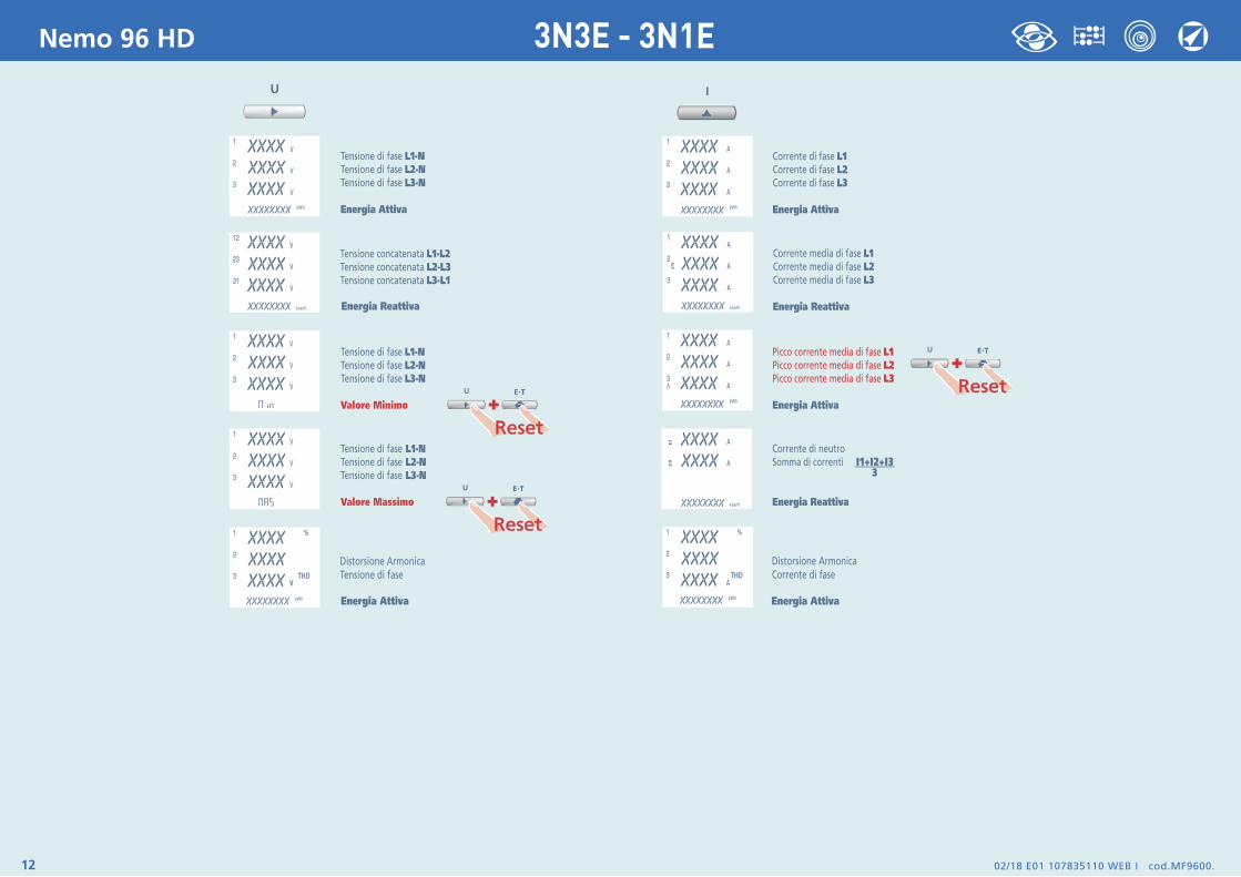
Nemo 96 HD 3N3E - 3N1E
02/18 E01 10783511 WEB I cod.MF9600. 13
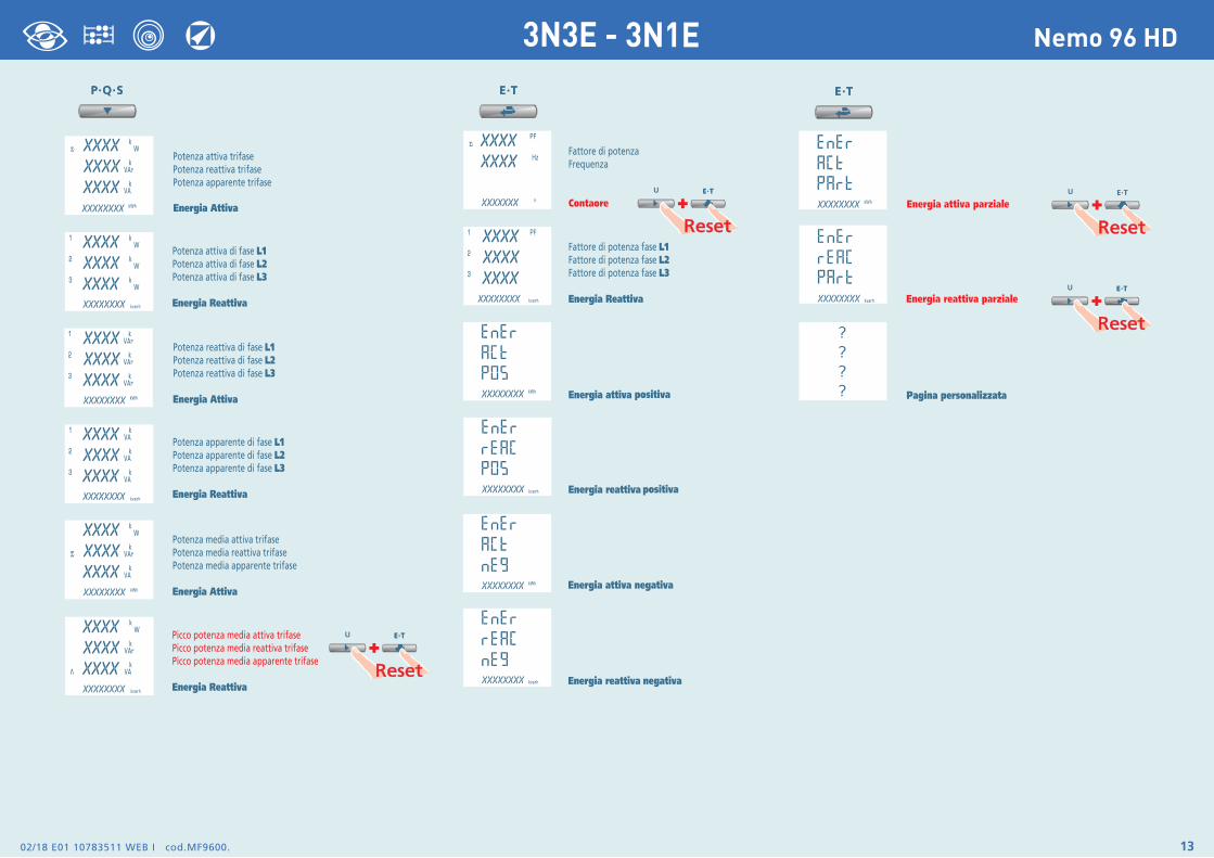
Nemo 96 HD3N3E - 3N1E
02/18 E01 107835110 WEB I cod.MF9600.14
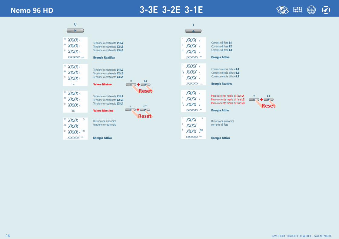
Nemo 96 HD 3-3E 3-2E 3-1E

02/18 E01 10783511 WEB I cod.MF9600. 15
Nemo 96 HD3-3E 3-2E 3-1E
02/18 E01 107835110 WEB I cod.MF9600.16
Nemo 96 HD 1N1E
02/18 E01 10783511 WEB I cod.MF9600. 17
Nemo 96 HD1N1E
02/18 E01 107835110 WEB I cod.MF9600.18
Nemo 96 HD
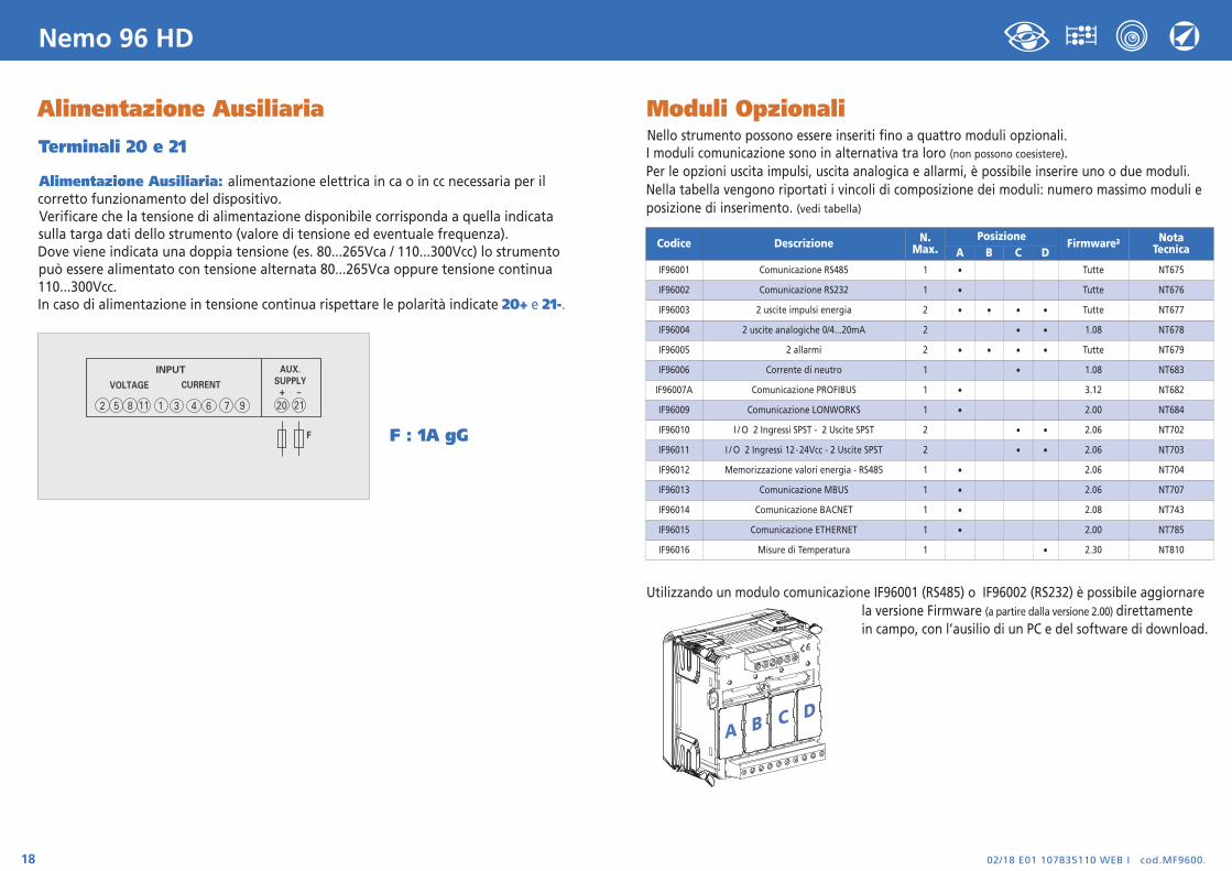
Alimentazione Ausiliaria
Terminali 20 e 21
Alimentazione Ausiliaria: alimentazione elettrica in ca o in cc necessaria per ilcorretto funzionamento del dispositivo.Verificare che la tensione di alimentazione disponibile corrisponda a quella indicata sulla targa dati dello strumento (valore di tensione ed eventuale frequenza).Dove viene indicata una doppia tensione (es. 80...265Vca / 110...300Vcc) lo strumento può essere alimentato con tensione alternata 80...265Vca oppure tensione continua 110...300Vcc.In caso di alimentazione in tensione continua rispettare le polarità indicate 20+ e 21-.
F : 1A gG
INPUT
VOLTAGE CURRENT
2 5 8 1 3 6 94 711 20
AUX.SUPPLY
21+ –
F
Moduli OpzionaliNello strumento possono essere inseriti fino a quattro moduli opzionali. I moduli comunicazione sono in alternativa tra loro (non possono coesistere). Per le opzioni uscita impulsi, uscita analogica e allarmi, è possibile inserire uno o due moduli. Nella tabella vengono riportati i vincoli di composizione dei moduli: numero massimo moduli e posizione di inserimento. (vedi tabella)
Utilizzando un modulo comunicazione IF96001 (RS485) o IF96002 (RS232) è possibile aggiornare la versione Firmware (a partire dalla versione 2.00) direttamente in campo, con l’ausilio di un PC e del software di download.
A B C D
Codice Descrizione N.Max.
PosizioneFirmware2 Nota
TecnicaA B C DIF96001 Comunicazione RS485 1 • Tutte NT675
IF96002 Comunicazione RS232 1 • Tutte NT676
IF96003 2 uscite impulsi energia 2 • • • • Tutte NT677
IF96004 2 uscite analogiche 0/4...20mA 2 • • 1.08 NT678
IF96005 2 allarmi 2 • • • • Tutte NT679
IF96006 Corrente di neutro 1 • 1.08 NT683
IF96007A Comunicazione PROFIBUS 1 • 3.12 NT682
IF96009 Comunicazione LONWORKS 1 • 2.00 NT684
IF96010 I / O 2 Ingressi SPST - 2 Uscite SPST 2 • • 2.06 NT702
IF96011 I / O 2 Ingressi 12-24Vcc - 2 Uscite SPST 2 • • 2.06 NT703
IF96012 Memorizzazione valori energia - RS485 1 • 2.06 NT704
IF96013 Comunicazione MBUS 1 • 2.06 NT707
IF96014 Comunicazione BACNET 1 • 2.08 NT743
IF96015 Comunicazione ETHERNET 1 • 2.00 NT785
IF96016 Misure di Temperatura 1 • 2.30 NT810
02/18 E01 10783511 WEB I cod.MF9600. 19
Nemo 96 HD
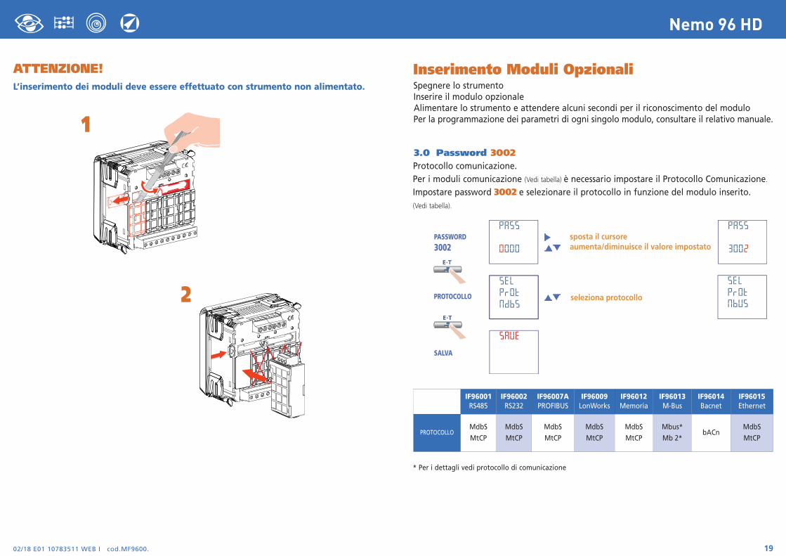
Inserimento Moduli OpzionaliSpegnere lo strumentoInserire il modulo opzionaleAlimentare lo strumento e attendere alcuni secondi per il riconoscimento del moduloPer la programmazione dei parametri di ogni singolo modulo, consultare il relativo manuale.
3.0 Password 3002Protocollo comunicazione.Per i moduli comunicazione (Vedi tabella) è necessario impostare il Protocollo Comunicazione.Impostare password 3002 e selezionare il protocollo in funzione del modulo inserito.(Vedi tabella).
* Per i dettagli vedi protocollo di comunicazione
IF96001RS485
IF96002RS232
IF96007APROFIBUS
IF96009LonWorks
IF96012Memoria
IF96013M-Bus
IF96014Bacnet
IF96015Ethernet
PROTOCOLLOMdbS
MtCP
MdbS
MtCP
MdbS
MtCP
MdbS
MtCP
MdbS
MtCP
Mbus*
Mb 2*bACn
MdbS
MtCP
ATTENZIONE!L’inserimento dei moduli deve essere effettuato con strumento non alimentato.
1
2
02/18 E01 107835110 WEB I cod.MF9600.20
Nemo 96 HD
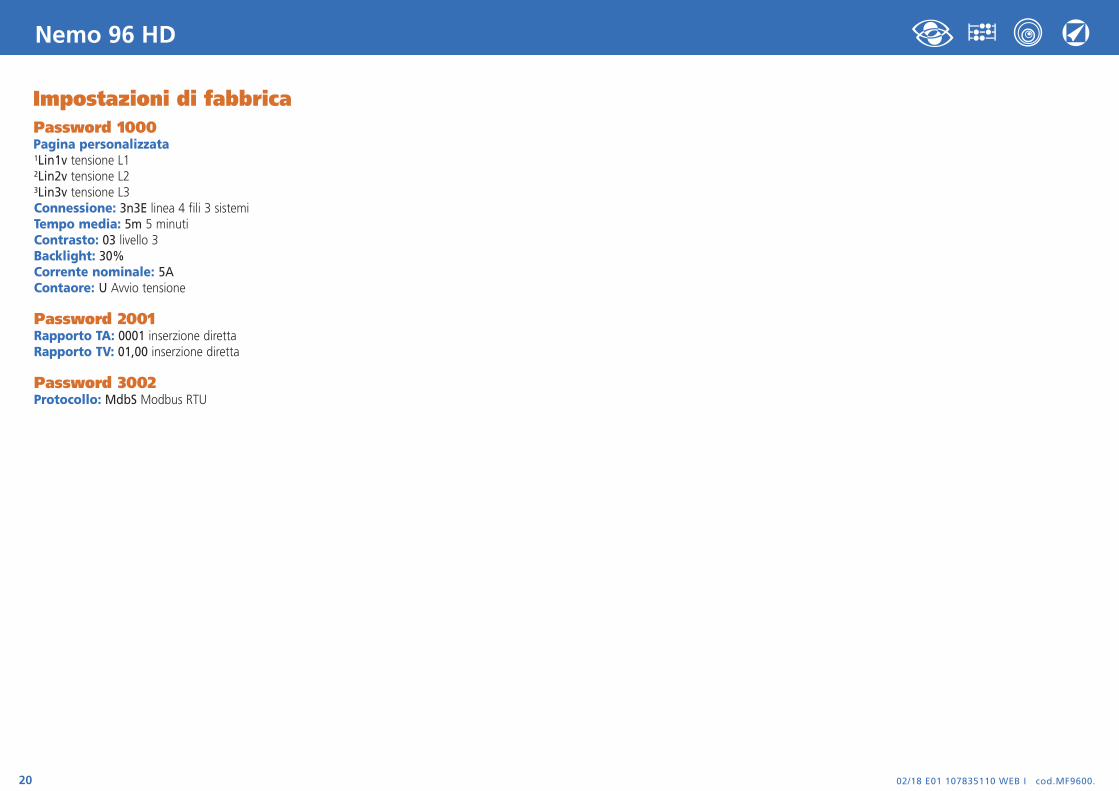
Impostazioni di fabbricaPassword 1000Pagina personalizzata1Lin1v tensione L12Lin2v tensione L23Lin3v tensione L3Connessione: 3n3E linea 4 fili 3 sistemiTempo media: 5m 5 minutiContrasto: 03 livello 3Backlight: 30%Corrente nominale: 5AContaore: U Avvio tensione
Password 2001Rapporto TA: 0001 inserzione direttaRapporto TV: 01,00 inserzione diretta
Password 3002Protocollo: MdbS Modbus RTU
Nemo 96 HD
Via Travaglia 7 20094 CORSICO (MI) Tel. 02 44 878.1 Fax 02 45 03 448 +39 02 45 86 76 63 [email protected]
www.imeitaly.com
02/18 E01 10783511WEB
E cod.M
F960
0.
02/18 E01 10783511 WEB E cod.MF9600.2
Nemo 96 HD
The technical documentation for the product is available on www.imeitaly.com website in the “Technical documentation” area, type in the field “Technical note code NT680”.
MultimeteringThey measure anddisplay simultaneouslymore quantities
Energy countingThey quantify theenergy consumption
CommunicationThey communicate themeasurements carriedat a distance
Interface differentways of communication
Measuring andMonitoringThey measure andreport specificinvolved conditions
I.M.E
. S.p.
A. re
serve
s the
right,
to m
odify
the t
echn
ical c
harac
terist
ics w
ithou
t noti
ce.
IndexWiring Diagrams page 3
Mounting instructions page 3
Programming page 4-5
Phase sequence diagnostic page 5
Level 1 Password 1000 page 6-9
Level 2 Password 2001 page 10
Level 3 Password 3002 page 19
Display page 11Reset page 11
3-phase 4 wires page 12-13
3-phase 3 wires page14-15
Single-phase page 16-178
Auxiliary Supply page 18
Optional Modules page 18
Connection optional modules page 19
Factory settings page 20
02/18 E01 10783511 WEB E cod.MF9600. 3
Nemo 96 HD
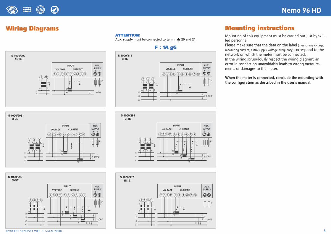
ATTENTION!Aux. supply must be connected to terminals 20 and 21.
Wiring Diagrams
F : 1A gG
Mounting instructionsMounting of this equipment must be carried out just by skil-led personnel. Please make sure that the data on the label (measuring voltage,measuring current, extra supply voltage, frequency) correspond to thenetwork on which the meter must be connected. In the wiring scrupulously respect the wiring diagram; anerror in connection unavoidably leads to wrong measure-ments or damages to the meter.
When the meter is connected, conclude the mounting withthe configuration as described in the user's manual.
X
XX
S1
P1
S1
P1
a
A
b
B
a
A
b
BL1
L2
L3
LOAD
2 5 8
INPUT
VOLTAGE CURRENT
20
AUX.SUPPLY
21+ –
2 5 8 1 3 6 94 711
F
2 5 8 111 3 6 94 7
S1
P1
a
A
b
BL
NLOADX
20
AUX.SUPPLY
2121+ –
2 11
INPUT
VOLTAGE CURRENT
F
X
XX
S1
P1 S1
P1 S1
P1
a
A
b
B
a
A
b
BL1
L2
L3
LOAD
2 5 8
INPUT
VOLTAGE CURRENT
20
AUX.SUPPLY
21+ –
2 5 8 1 3 6 94 711
F
S 1000/2921N1E
S 1000/2933-2E
S 1000/2943-3E
X
XX
S1
P1
a
A
b
B
a
A
b
BL1
L2
L3
LOAD
2 5 8
INPUT
VOLTAGE CURRENT
20
AUX.SUPPLY
21+ –
2 5 8 1 3 6 94 711
F
S 1000/3143-1E
X
XX
S1
P1 S1
P1 S1
P1
a
AL1
L2
L3
NX X X
LOAD
INPUT
VOLTAGE CURRENT
20
AUX.SUPPLY
21+ –
2 5 8 1 3 6 94 711
2 5 8 11F
S 1000/2953N3E
X
XX
S1
P1
a
A
X X X
LOAD
INPUT
VOLTAGE CURRENT
20
AUX.SUPPLY
2121+ –
2 5 8 1 3 6 94 711
2 5 8 11
L1
L2
L3
N
F
S 1000/3173N1E
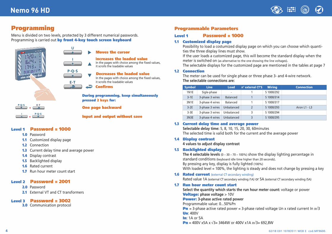
ProgrammingMenu is divided on two levels, protected by 3 different numerical passwords.Programming is carried out by front 4-key touch screen keyboard
Moves the cursor
Increases the loaded valueIn the pages with choice among the fixed values, it scrolls the loadable values
Decreases the loaded valueIn the pages with choice among the fixed values, it scrolls the loadable values
Confirms
During programming, keep simultaneously pressed 2 keys for:
One page backward
Input and output without save
Level 1 Password = 10001.0 Password1.1 Customized display page1.2 Connection1.3 Current delay time and average power1.4 Display contrast1.5 Backlighted display1.6 Rated current1.7 Run hour meter count start
Level 2 Password = 20012.0 Password2.1 External VT and CT transformers
Level 3 Password = 30023.0 Communication protocol
02/18 E01 10783511 WEB E cod.MF9600.4
Nemo 96 HD
Programmable Parameters
Level 1 Password = 10001.1 Customized display page
Possibility to load a costumized display page on which you can choose which quanti-ties the three display lines must show.If the user loads a customized page, this will become the standard display when the meter is switched on (as alternative to the one showing the line voltages).The selectable displays for the customized page are mentioned in the tables at page 7
1.2 ConnectionThe meter can be used for single phase or three phase 3- and 4-wire network.The selectable connections are:
1.3 Current delay time and average powerSelectable delay time: 5, 8, 10, 15, 20, 30, 60minutesThe selected time is valid both for the current and the average power
1.4 Display contrast4 values to adjust display contrast
1.5 Backlighted display The 4 selectable levels (0 – 30 – 70 – 100%) show the display lighting percentage in standard conditions (keyboard idle time higher than 20 seconds). By pressing any key, display is fully lighted (100%)
With loaded level = 100%, the lighting is steady and does not change by pressing a key
1.6 Rated current (external CT secondary winding)Rated value 1A (external CT secondary winding /1A) or 5A (external CT secondary winding /5A)
1.7 Run hour meter count startSelect the quantity which starts the run hour meter count: voltage or powerVoltage: phase voltage > 10VPower: 3-phase active rated power Programmable value: 0...50%PnPn = 3-phase active rated power = 3-phase rated voltage Un x rated current In x√3 Un: 400VIn: 1A or 5APn = 400V x5A x √3= 3464W or 400V x1A x√3= 692,8W
Symbol Line Load n° external CT’S Wiring Connection
1N1E Sigle-phase - 1 S 1000/292
3-1E 3-phase 3 wires Balanced 1 S 1000/314
3N1E 3-phase 4 wires Balanced 1 S 1000/317
3-2E 3-phase 3 wires Unbalanced 2 S 1000/293 Aron L1 - L3
3-3E 3-phase 3 wires Unbalanced 3 S 1000/294
3N3E 3-phase 4 wires Unbalanced 3 S 1000/295
02/18 E01 10783511 WEB E cod.MF9600. 5
Nemo 96 HD
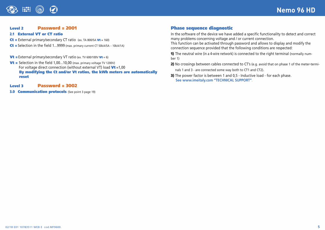
Level 2 Password = 20012.1 External VT or CT ratioCt = External primary/secondary CT ratio (ex. TA 800/5A Vt = 160)Ct = Selection in the field 1...9999 (max. primary current CT 50kA/5A – 10kA/1A)
Vt = External primary/secondary VT ratio (ex. TV 600/100V Vt = 6)
Vt = Selection in the field 1,00...10,00 (max. primary voltage TV 1200V)For voltage direct connection (without external VT) load Vt =1,00By modifying the Ct and/or Vt ratios, the kWh meters are automatically reset
Level 3 Password = 30023.0 Communication protocols (See point 3 page 19)
Phase sequence diagnosticIn the software of the device we have added a specific functionality to detect and correctmany problems concerning voltage and / or current connection.This function can be activated through password and allows to display and modify theconnection sequence provided that the following conditions are respected:
1) The neutral wire (in a 4-wire network) is connected to the right terminal (normally num-ber 1)
2) No crossings between cables connected to CT’s (e.g. avoid that on phase 1 of the meter-termi- nals 1 and 3 - are connected some way both to CT1 and CT2).
3) The power factor is between 1 and 0,5 - Inductive load - for each phase.See www.imeitaly.com “TECHNICAL SUPPORT”.
02/18 E01 10783511 WEB E cod.MF9600.6
Nemo 96 HD
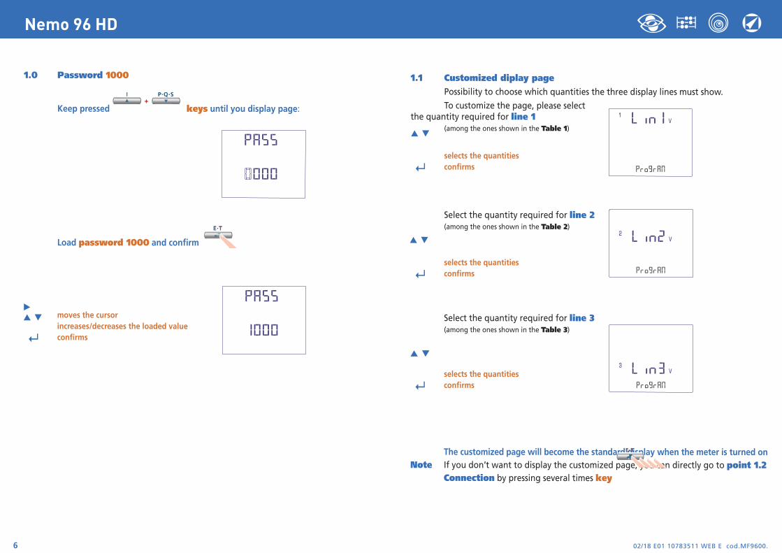
1.0 Password 1000
Keep pressed keys until you display page:
Load password 1000 and confirm
moves the cursorincreases/decreases the loaded value
↵ confirms
1.1 Customized diplay pagePossibility to choose which quantities the three display lines must show.
To customize the page, please selectthe quantity required for line 1
(among the ones shown in the Table 1)
selects the quantities
↵ confirms
Select the quantity required for line 2(among the ones shown in the Table 2)
selects the quantities
↵ confirms
Select the quantity required for line 3(among the ones shown in the Table 3)
selects the quantities
↵ confirms
The customized page will become the standard display when the meter is turned onNote If you don’t want to display the customized page, you can directly go to point 1.2
Connection by pressing several times key
02/18 E01 10783511 WEB E cod.MF9600. 7
Nemo 96 HD
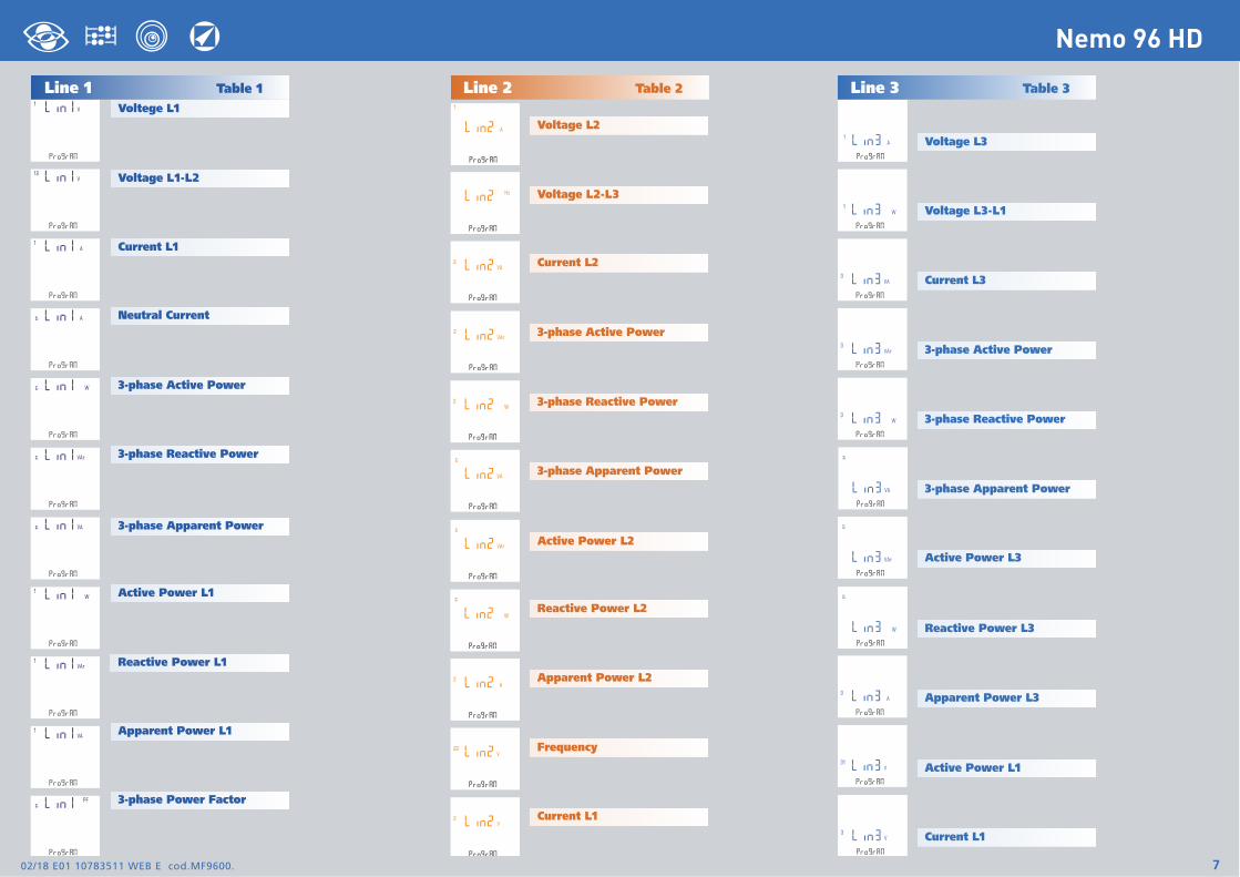
Line 1 Table 1Voltege L1
Voltage L2
Line 2 Table 2 Line 3 Table 3
Voltage L3
Voltage L1-L2
Current L1
3-phase Active Power
3-phase Reactive Power
3-phase Apparent Power
Active Power L1
Reactive Power L1
Apparent Power L1
3-phase Power Factor
Voltage L2-L3
Current L2
3-phase Active Power
3-phase Reactive Power
3-phase Apparent Power
Active Power L2
Reactive Power L2
Apparent Power L2
Frequency
Current L1
Voltage L3-L1
Current L3
3-phase Active Power
3-phase Reactive Power
3-phase Apparent Power
Active Power L3
Reactive Power L3
Apparent Power L3
Active Power L1
Current L1
Neutral Current
02/18 E01 10783511 WEB E cod.MF9600.8
Nemo 96 HD
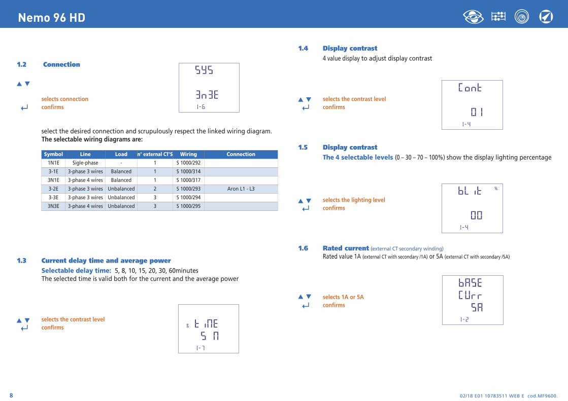
1.2 Connection
selects connection
↵ confirms
select the desired connection and scrupulously respect the linked wiring diagram.The selectable wiring diagrams are:
1.3 Current delay time and average powerSelectable delay time: 5, 8, 10, 15, 20, 30, 60minutesThe selected time is valid both for the current and the average power
selects the contrast level
↵ confirms
1.4 Display contrast4 value display to adjust display contrast
selects the contrast level
↵ confirms
1.5 Display contrastThe 4 selectable levels (0 – 30 – 70 – 100%) show the display lighting percentage
selects the lighting level
↵ confirms
1.6 Rated current (external CT secondary winding)Rated value 1A (external CT with secondary /1A) or 5A (external CT with secondary /5A)
selects 1A or 5A
↵ confirms
Symbol Line Load n° external CT’S Wiring Connection
1N1E Sigle-phase - 1 S 1000/292
3-1E 3-phase 3 wires Balanced 1 S 1000/314
3N1E 3-phase 4 wires Balanced 1 S 1000/317
3-2E 3-phase 3 wires Unbalanced 2 S 1000/293 Aron L1 - L3
3-3E 3-phase 3 wires Unbalanced 3 S 1000/294
3N3E 3-phase 4 wires Unbalanced 3 S 1000/295
02/18 E01 10783511 WEB E cod.MF9600. 9
Nemo 96 HD
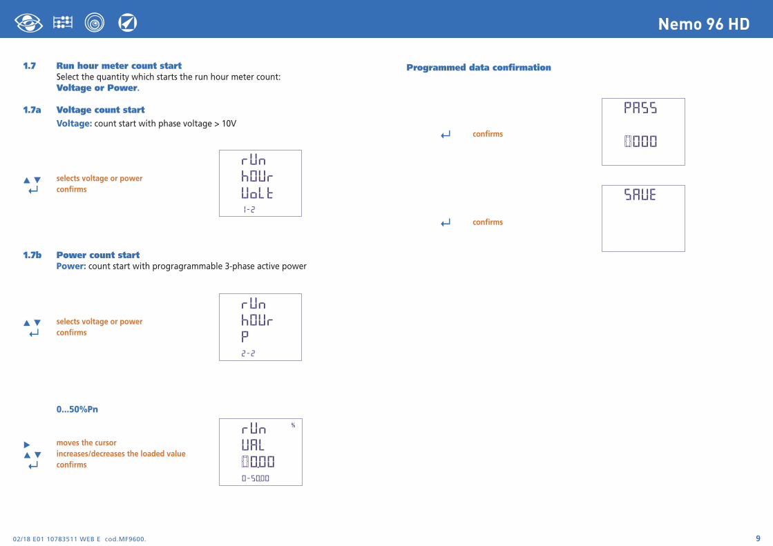
Programmed data confirmation
↵ confirms
↵ confirms
1.7 Run hour meter count startSelect the quantity which starts the run hour meter count:Voltage or Power.
1.7a Voltage count startVoltage: count start with phase voltage > 10V
selects voltage or power
↵ confirms
1.7b Power count startPower: count start with progragrammable 3-phase active power
selects voltage or power ↵ confirms
0...50%Pn
moves the cursorincreases/decreases the loaded value
↵ confirms
02/18 E01 10783511 WEB E cod.MF9600.10
Nemo 96 HD
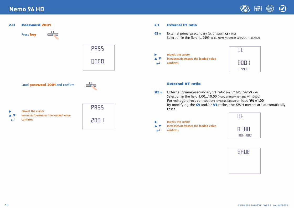
2.0 Password 2001
Press key
Load password 2001 and confirm
moves the cursorincreases/decreases the loaded value
↵ confirms
2.1 External CT ratio
Ct = External primary/secondary (ex. CT 800/5A Ct = 160)Selection in the field 1...9999 (max. primary current 50kA/5A – 10kA/1A)
moves the cursorincreases/decreases the loaded value
↵ confirms
External VT ratio
Vt = External primary/secondary VT ratio (ex. VT 600/100V Vt = 6)
Selection in the field 1,00...10,00 (max. primary voltage VT 1200V)For voltage direct connection (without external VT) load Vt =1,00By modifying the Ct and/or Vt ratios, the KWH meters are automaticallyreset.
moves the cursorincreases/decreases the loaded value
↵ confirms
02/18 E01 10783511 WEB E cod.MF9600. 11
Nemo 96 HD
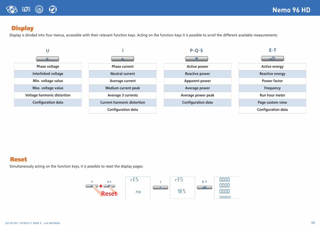
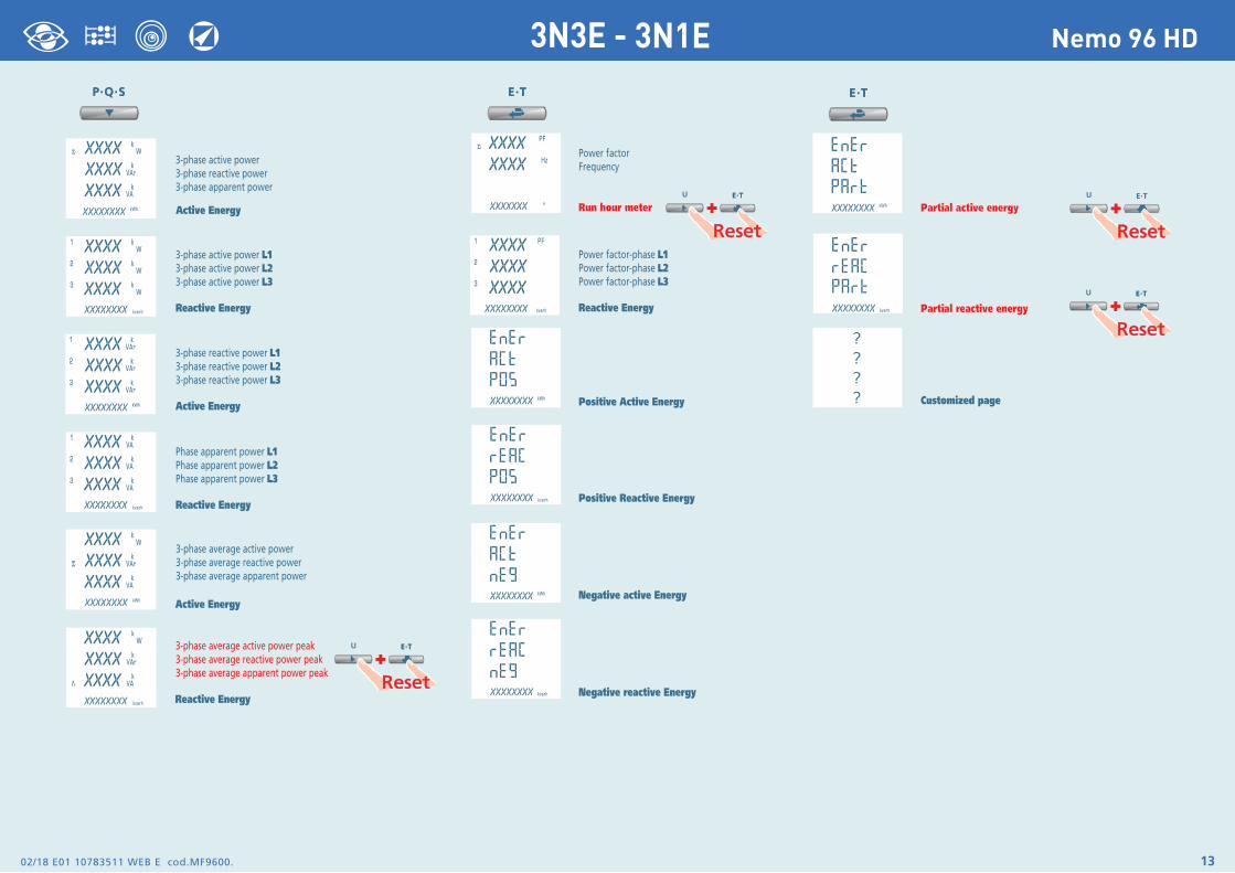
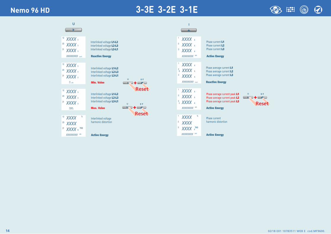
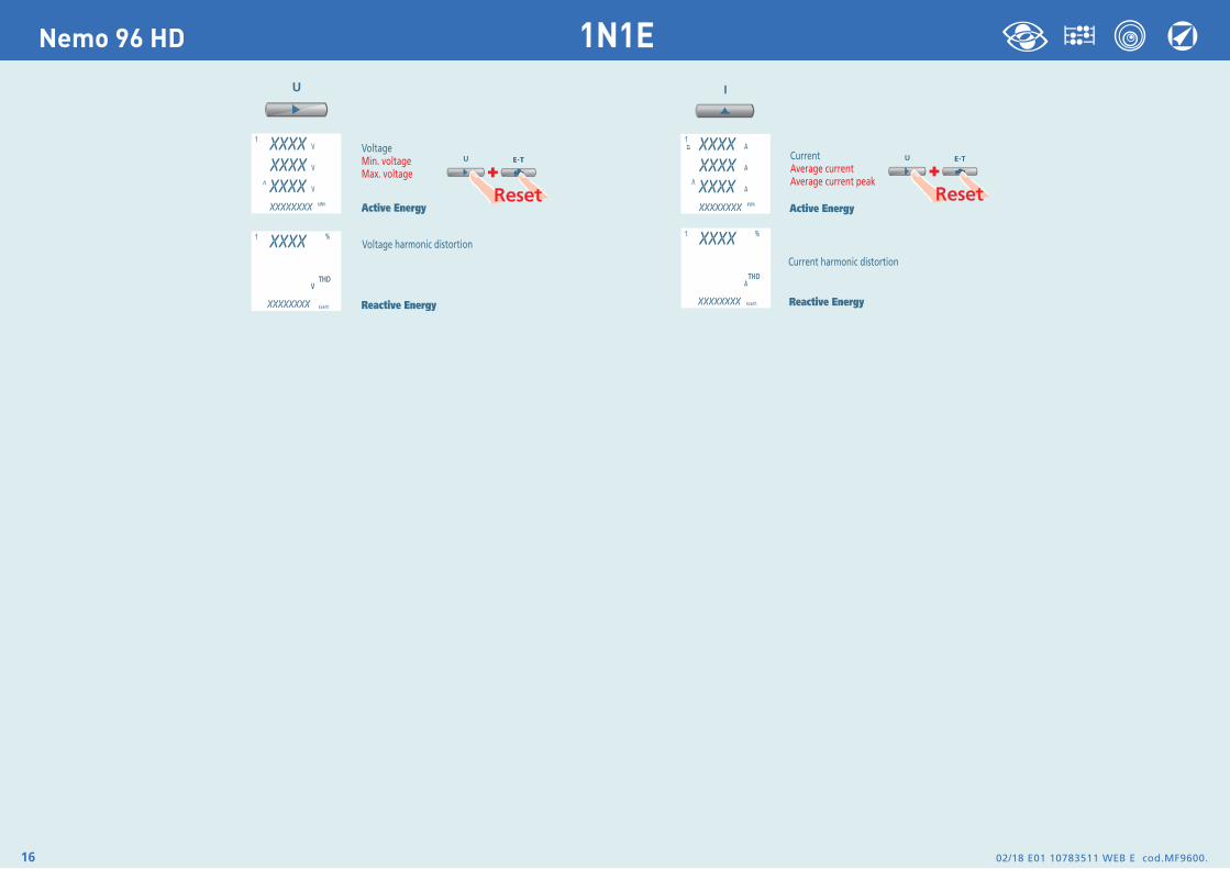
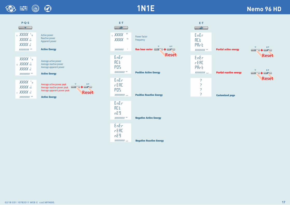
DisplayDisplay is divided into four menus, accessible with their relevant function keys. Acting on the function keys it is possible to scroll the different available measurements:
ResetSimultaneously acting on the function keys, it is possible to reset the display pages:
Phase voltage
Interlinked voltage
Min. voltage value
Max. voltage value
Voltage harmonic distortion
Configuration data
Phase current
Neutral current
Average current
Medium current peak
Average 3 currents
Current harmonic distortion
Configuration data
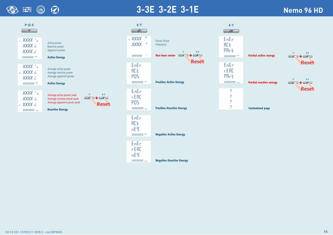
Active power
Reactive power
Apparent power
Average power
Average power peak
Configuration data
Active energy
Reactive energy
Power factor
Frequency
Run hour meter
Page custom view
Configuration data
+
02/18 E01 10783511 WEB E cod.MF9600. 13
Nemo 96 HD3N3E - 3N1E
02/18 E01 10783511 WEB E cod.MF9600.14
Nemo 96 HD 3-3E 3-2E 3-1E
02/18 E01 10783511 WEB E cod.MF9600. 15
Nemo 96 HD3-3E 3-2E 3-1E
02/18 E01 10783511 WEB E cod.MF9600.16
Nemo 96 HD 1N1E
02/18 E01 10783511 WEB E cod.MF9600. 17
Nemo 96 HD1N1E
02/18 E01 10783511 WEB E cod.MF9600.18
Nemo 96 HD
Auxiliary Supply
Terminals 20 and 21
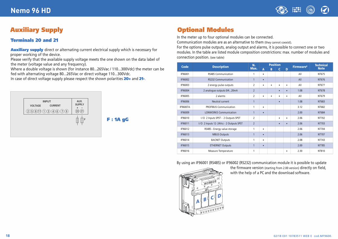
Auxiliary supply direct or alternating current electrical supply which is necessary for proper working of the device.Please verify that the available supply voltage meets the one shown on the data label of the meter (voltage value and any frequency).Where a double voltage is shown (for instance 80...265Vac / 110...300Vdc) the meter can be fed with alternating voltage 80...265Vac or direct voltage 110...300Vdc.In case of direct voltage supply please respect the shown polarities 20+ and 21-.
F : 1A gG
INPUT
VOLTAGE CURRENT
2 5 8 1 3 6 94 711 20
AUX.SUPPLY
21+ –
F
Optional Modules In the meter up to four optional modules can be connected.Communication modules are as an alternative to them (they cannot coexist).For the options pulse outputs, analog output and alarms, it is possible to connect one or two modules. In the table are listed module composition constrictions: max. number of modules and connection position. (see table)
By using an IF96001 (RS485) or IF96002 (RS232) communication module it is possible to updatethe firmware version (starting from 2.00 version) directly on field,with the help of a PC and the download software.
A B C D
Code Description N.Max.
PositionFirmware2 Technical
NoteA B C DIF96001 RS485 Communication 1 • All NT675
IF96002 RS232 Communication 1 • All NT676
IF96003 2 energy pulse outputs 2 • • • • All NT677
IF96004 2 analogue outputs 0/4...20mA 2 • • 1.08 NT678
IF96005 2 alarms 2 • • • • All NT679
IF96006 Neutral current 1 • 1.08 NT683
IF96007A PROFIBUS Communication 1 • 3.12 NT682
IF96009 LONWORKS Communication 1 • 2.00 NT684
IF96010 I / O 2 Inputs SPST - 2 Outputs SPST 2 • • 2.06 NT702
IF96011 I / O 2 Inputs 12-24Vcc - 2 Outputs SPST 2 • • 2.06 NT703
IF96012 RS485 - Energy value storage 1 • 2.06 NT704
IF96013 MBUS Outputs 1 • 2.06 NT707
IF96014 BACNET Outputs 1 • 2.08 NT743
IF96015 ETHERNET Outputs 1 • 2.00 NT785
IF96016 Measure Temperature 1 • 2.30 NT810
02/18 E01 10783511 WEB E cod.MF9600. 19
Nemo 96 HD
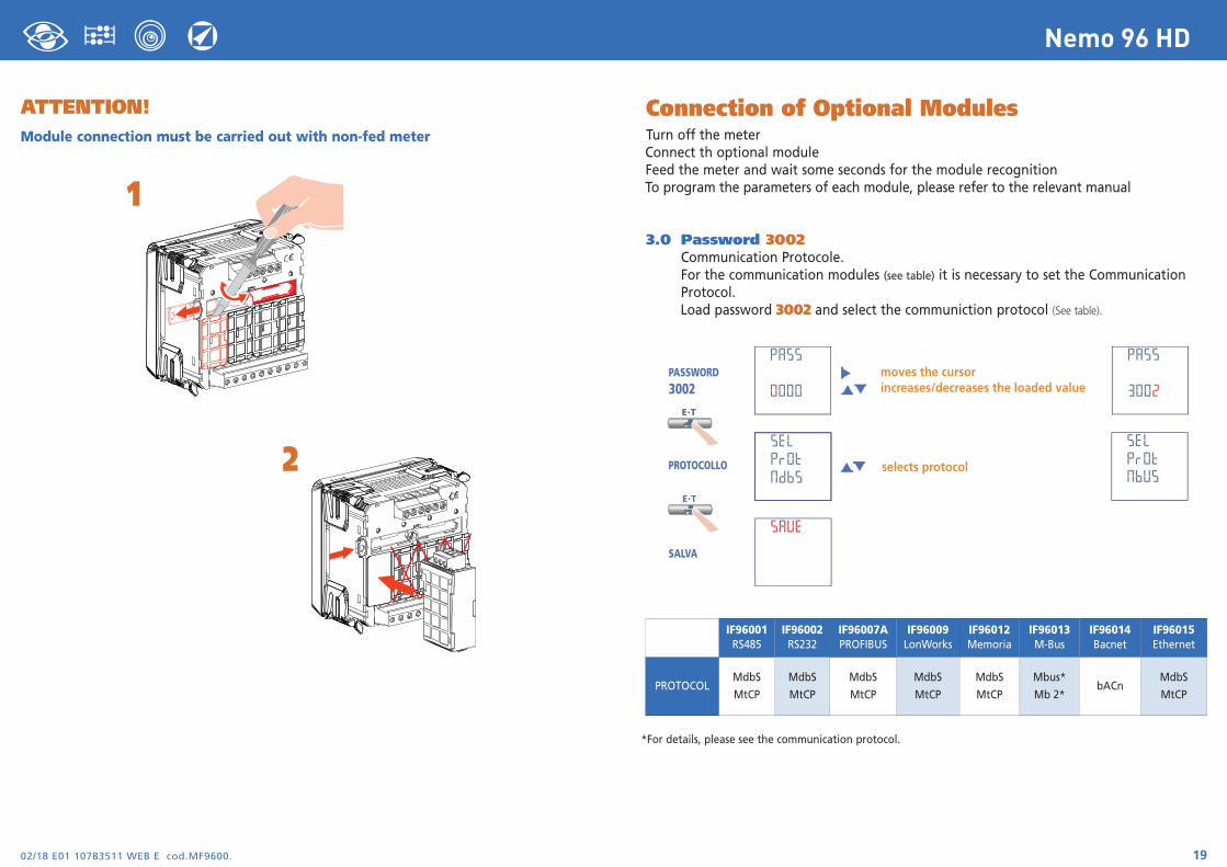
Connection of Optional ModulesTurn off the meterConnect th optional moduleFeed the meter and wait some seconds for the module recognitionTo program the parameters of each module, please refer to the relevant manual
3.0 Password 3002Communication Protocole.For the communication modules (see table) it is necessary to set the Communication Protocol.Load password 3002 and select the communiction protocol (See table).
*For details, please see the communication protocol.
IF96001RS485
IF96002RS232
IF96007APROFIBUS
IF96009LonWorks
IF96012Memoria
IF96013M-Bus
IF96014Bacnet
IF96015Ethernet
PROTOCOLMdbS
MtCP
MdbS
MtCP
MdbS
MtCP
MdbS
MtCP
MdbS
MtCP
Mbus*
Mb 2*bACn
MdbS
MtCP
ATTENTION!Module connection must be carried out with non-fed meter
1
2
02/18 E01 10783511 WEB E cod.MF9600.20
Nemo 96 HD
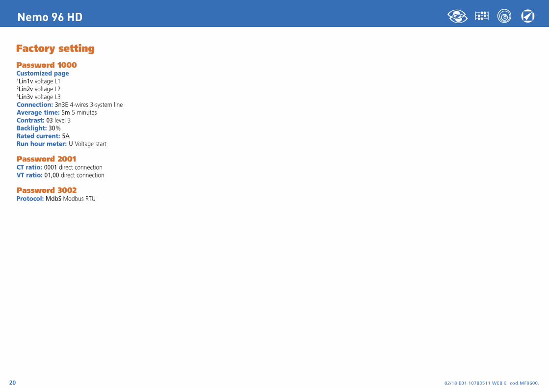
Factory setting
Password 1000Customized page1Lin1v voltage L12Lin2v voltage L23Lin3v voltage L3Connection: 3n3E 4-wires 3-system lineAverage time: 5m 5 minutesContrast: 03 level 3Backlight: 30%Rated current: 5ARun hour meter: U Voltage start
Password 2001CT ratio: 0001 direct connectionVT ratio: 01,00 direct connection
Password 3002Protocol: MdbS Modbus RTU
Nemo 96 HD
Via Travaglia 7 20094 CORSICO (MI) Tel. 02 44 878.1 Fax 02 45 03 448 +39 02 45 86 76 63 [email protected]
www.imeitaly.com
02/18 E01 10783511WEB
F co
d.M
F960
0.
02/18 E01 10783511 WEB F cod.MF9600.2
Nemo 96 HD
IndexSchéma de raccordement page 3
Instructions pour le montage page 3
Programmation page 4 et 5
Diagnostic sequence phases page 5
Niveau 1 Mot de passe 1000 page 6 et 9
Niveau 2 Mot de passe 2001 page 10
Niveau 3 Mot de passe 3002 page 19
Affichage page 11Reset page 11
Triphasé 4 fils page 12 et 13
Triphasé 3 fils page 14 et 15
Monophasé page 16 et 17
Alimentation Auxiliaire page 18
Modules optionnels page 18
Insertion de modules optionnels page 19
Configuration d’usine page 20
MultimesureMesurent et affichentplusieurs grandeurs enmême temps
ComptageénergieQuantifient lesconsommationsd'énergie
CommunicationCommuniquent lesmesures prises àdistanceInterfacent différentsmodes decommunication
Mesure etcontrôle Mesurent etinterviennent, ensignalant conditionsparticulières.
I.M.E
. S.p.
A. se
rése
rve à
chaq
ue m
omen
t, de m
odifie
r les c
aracté
ristiq
ues t
echn
iques
sans
préa
vis éc
rit
La documentation technique pour le produit est disponible sur le site www.imeitaly.com dans la zone “Documentazione Tecnica” area, taper dans le champ “Codice Nota Tecnica NT680”.
02/18 E01 10783511 WEB F cod.MF9600. 3
Nemo 96 HD
ATTENTION!Raccorder l’alimentation auxiliaire sur les bornes 20 et 21.
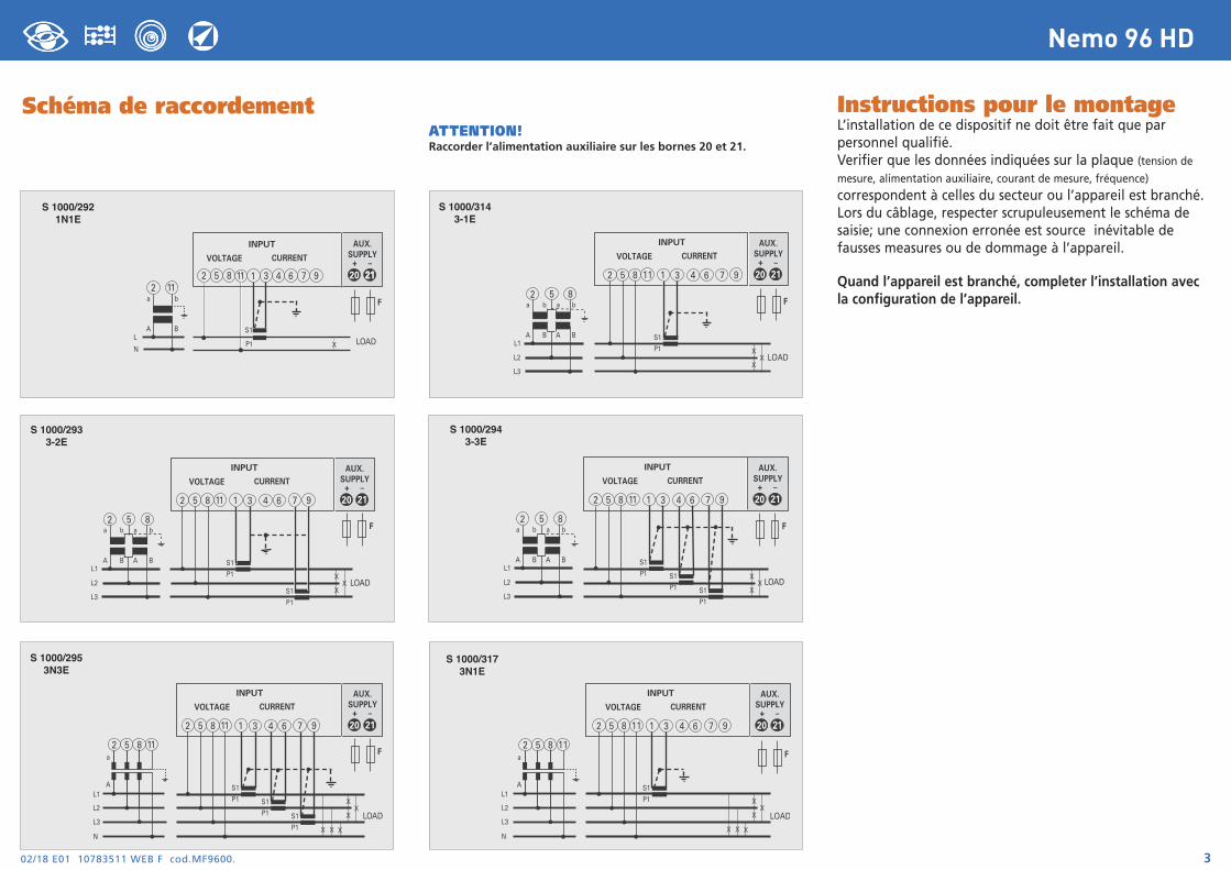
Schéma de raccordement Instructions pour le montageL’installation de ce dispositif ne doit être fait que parpersonnel qualifié.Verifier que les données indiquées sur la plaque (tension demesure, alimentation auxiliaire, courant de mesure, fréquence)
correspondent à celles du secteur ou l’appareil est branché.Lors du câblage, respecter scrupuleusement le schéma desaisie; une connexion erronée est source inévitable defausses measures ou de dommage à l’appareil.
Quand l’appareil est branché, completer l’installation avecla configuration de l’appareil.
X
XX
S1
P1
S1
P1
a
A
b
B
a
A
b
BL1
L2
L3
LOAD
2 5 8
INPUT
VOLTAGE CURRENT
20
AUX.SUPPLY
21+ –
2 5 8 1 3 6 94 711
F
2 5 8 111 3 6 94 7
S1
P1
a
A
b
BL
NLOADX
20
AUX.SUPPLY
2121+ –
2 11
INPUT
VOLTAGE CURRENT
F
X
XX
S1
P1 S1
P1 S1
P1
a
A
b
B
a
A
b
BL1
L2
L3
LOAD
2 5 8
INPUT
VOLTAGE CURRENT
20
AUX.SUPPLY
21+ –
2 5 8 1 3 6 94 711
F
S 1000/2921N1E
S 1000/2933-2E
S 1000/2943-3E
X
XX
S1
P1
a
A
b
B
a
A
b
BL1
L2
L3
LOAD
2 5 8
INPUT
VOLTAGE CURRENT
20
AUX.SUPPLY
21+ –
2 5 8 1 3 6 94 711
F
S 1000/3143-1E
X
XX
S1
P1 S1
P1 S1
P1
a
AL1
L2
L3
NX X X
LOAD
INPUT
VOLTAGE CURRENT
20
AUX.SUPPLY
21+ –
2 5 8 1 3 6 94 711
2 5 8 11F
S 1000/2953N3E
X
XX
S1
P1
a
A
X X X
LOAD
INPUT
VOLTAGE CURRENT
20
AUX.SUPPLY
2121+ –
2 5 8 1 3 6 94 711
2 5 8 11
L1
L2
L3
N
F
S 1000/3173N1E
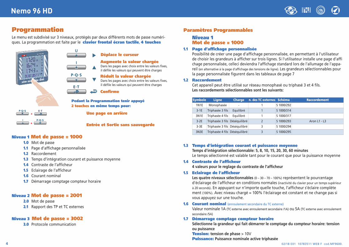
ProgrammationLe menu est subdivisé sur 3 niveaux, protégés par deux différents mots de passe numéri-ques. La programmation est faite par le clavier frontal écran tactile, 4 touches
Dèplace le curseur
Augmente la valeur chargéeDans les pages avec choix entre les valeurs fixes, il défile les valeurs qui peuvent être charges
Réduit la valeur chargéeDans les pages avec choix entre les valeurs fixes, il défile les valeurs qui peuvent être charges
Confirme
Pedant la Programmation tenir appuyé2 touches en même temps pour:
Une page en arrière
Entrée et Sortie sans sauvegarde
Niveau 1 Mot de passe = 10001.0 Mot de passe1.1 Page d’affichage personnalisée1.2 Raccordement1.3 Temps d’intégration courant et puissance moyenne1.4 Contraste de l’afficheur1.5 Eclairage de l’afficheur1.6 Courant nominal1.7 Démarrage comptage compteur horaire
Niveau 2 Mot de passe = 20012.0 Mot de passe2.1 Rapport des TP et TC externes
Niveau 3 Mot de passe = 30023.0 Protocole communication
02/18 E01 10783511 WEB F cod.MF9600.4
Nemo 96 HD
Paramètres Programmables
Niveau 1Mot de passe = 1000
1.1 Page d’affichage personnaliséePossibilité de créer une page d'affichage personnalisée, en permettant à l'utilisateur de choisir les grandeurs à afficher sur trois lignes. Si l'utilisateur installe une page d'affichage personnalisée, celleci deviendra l'affichage standard lors de l'allumage de l'appa-reil (en alternative à la page d'affichage des tensions de ligne). Les grandeurs sélectionnables pour la page personnalisée figurent dans les tableaux de page 7
1.2 RaccordementCet appareil peut être utilisé sur réseau monophasé ou triphasé 3 et 4 fils.Les raccordements sélectionnables sont les suivants:
1.3 Temps d'intégration courant et puissance moyenneTemps d'intégration sélectionnable: 5, 8, 10, 15, 20, 30, 60 minutesLe temps sélectionné est valable tant pour le courant que pour la puissance moyenne
1.4 Contraste de l’afficheur4 valeurs pour le reglage du contraste de l’afficheur
1.5 Eclairage de l'afficheurLes quatre niveaux sélectionnables (0 – 30 – 70 – 100%) représentent le pourcentage d'éclairage de l'afficheur en conditions normales (inactivité du clavier pour un temps supérieur
à 20 seconds). En appuyant sur n’importe quelle touche, l’afficheur s’éclaire complètement (100%). Avec niveau chargé = 100% l’éclairage est constant et ne change pas si vous appuyez sur une touche.
1.6 Courant nominal (enroulement secondaire du TC externe)
Valeur nominale 1A (TC externe avec enroulement secondaire /1A) ou 5A (TC externe avec enroulement
secondaire /5A)
1.7 Démarrage comptage compteur horaireSélectionne la grandeur qui fait démarrer le comptage du compteur horaire: tension ou puissanceTension: tension de phase > 10VPuissance: Puissance nominale active triphasée
Symbole Ligne Charge n. des TC externes Schéma Raccordement
1N1E Monophasée - 1 S 1000/292
3-1E Triphasée 3 fils Equilibré 1 S 1000/314
3N1E Triphasée 4 fils Equilibré 1 S 1000/317
3-2E Triphasée 3 fils Déséquilibré 2 S 1000/293 Aron L1 - L3
3-3E Triphasée 3 fils Déséquilibré 3 S 1000/294
3N3E Triphasée 4 fils Déséquilibré 3 S 1000/295
02/18 E01 10783511 WEB F cod.MF9600. 5
Nemo 96 HD
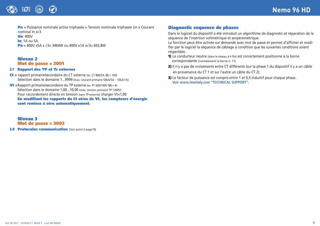
Pn = Puissance nominale active triphasée = Tension nominale triphasée Un x Courant nominal In x√3Un: 400VIn: 1A ou 5APn = 400V x5A x √3= 3464W ou 400V x1A x√3= 692,8W
Niveau 2Mot de passe = 2001
2.1 Rapport des TP et Tc externesCt = rapport primaire/secondaire du CT externe (es. CT 800/5A Ct = 160)
Sélection dans le domaine 1...9999 (max. courant primaire 50kA/5A – 10kA/1A)
Vt =Rapport primaire/secondaire du TP externe (es. PT 600/100V Vt = 6)
Sélection dans le domaine 1,00...10,00 (max. tension primaire TP 1200V)
Pour raccordement directe en tension (sans TP externe) charger Vt=1,00 En modifiant les rapports du Ct et/ou de Vt, les compteurs d'énergie sont remises à zéro automatiquement.
Niveau 3Mot de passe = 3002
3.0 Protocoles communication (Voir point 3 page19)
Diagnostic sequence de phasesDans le logiciel du dispositif a été introduit un algorithme de diagnostic et réparation de laséquence de l’insertion voltmétrique et ampèremétrique. La fonction peut être activée sur demande avec mot de passe et permet d’afficher et modi-fier par le logiciel la séquence de câblage à condition que les suivantes conditions soientrespectées:1) Le conducteur neutre (dans le réseau à 4 fils) est correctement positionné à la borne correspondante (normalement la borne n. 11).
2) Il n’y a pas de croisements entre CT différents (sur la phase 1 du dispositif il y a un câble
en provenance du CT 1 et sur l’autre un câble du CT 2).
3) Le facteur de puissance est compris entre 1 et 0,5 inductif pour chaque phase.Voir www.imeitaly.com “TECHNICAL SUPPORT”.
02/18 E01 10783511 WEB F cod.MF9600.6
Nemo 96 HD
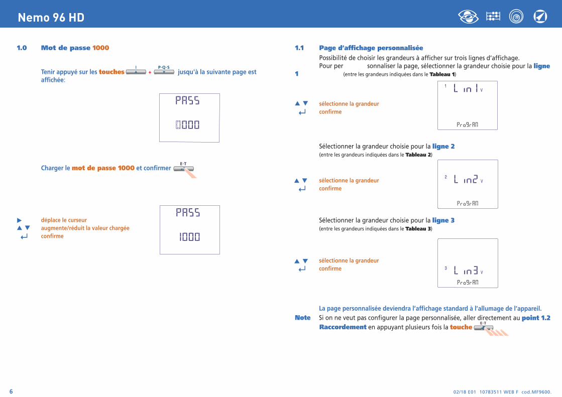
1.0 Mot de passe 1000
Tenir appuyé sur les touches jusqu'à la suivante page estaffichée:
Charger le mot de passe 1000 et confirmer
déplace le curseuraugmente/réduit la valeur chargée
↵ confirme
1.1 Page d’affichage personnaliséePossibilité de choisir les grandeurs à afficher sur trois lignes d’affichage. Pour per sonnaliser la page, sélectionner la grandeur choisie pour la ligne
1 (entre les grandeurs indiquées dans le Tableau 1)
sélectionne la grandeur
↵ confirme
Sélectionner la grandeur choisie pour la ligne 2(entre les grandeurs indiquées dans le Tableau 2)
sélectionne la grandeur
↵ confirme
Sélectionner la grandeur choisie pour la ligne 3(entre les grandeurs indiquées dans le Tableau 3)
sélectionne la grandeur
↵ confirme
La page personnalisée deviendra l’affichage standard à l’allumage de l’appareil.Note Si on ne veut pas configurer la page personnalisée, aller directement au point 1.2
Raccordement en appuyant plusieurs fois la touche
02/18 E01 10783511 WEB F cod.MF9600. 7
Nemo 96 HD
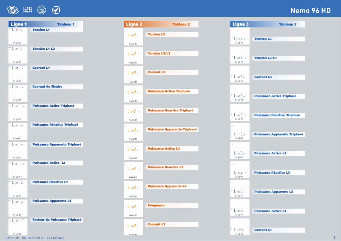
Ligne 1 Tableau 1Tension L1
Tension L2
Ligne 2 Tableau 2 Ligne 3 Tableau 3
Tension L3
Tension L1-L2
Courant L1
Puissance Active Triphasé
Puissance Réactive Triphasé
Puissance Apparente Triphasé
Puissance Active L1
Puissance Réactive L1
Puissance Apparente L1
Facteur de Puissance Triphasé
Tension L2-L3
Courant L2
Puissance Active Triphasé
Puissance Réactive Triphasé
Puissance Apparente Triphasé
Puissance Active L2
Puissance Réactive L2
Puissance Apparente L2
Fréquence
Courant L1
Tension L3-L1
Courant L3
Puissance Active Triphasé
Puissance Réactive Triphasé
Puissance Apparente Triphasé
Puissance Active L3
Puissance Réactive L3
Puissance Apparente L3
Puissance Active L1
Courant L1
Courant du Neutre
02/18 E01 10783511 WEB F cod.MF9600.8
Nemo 96 HD
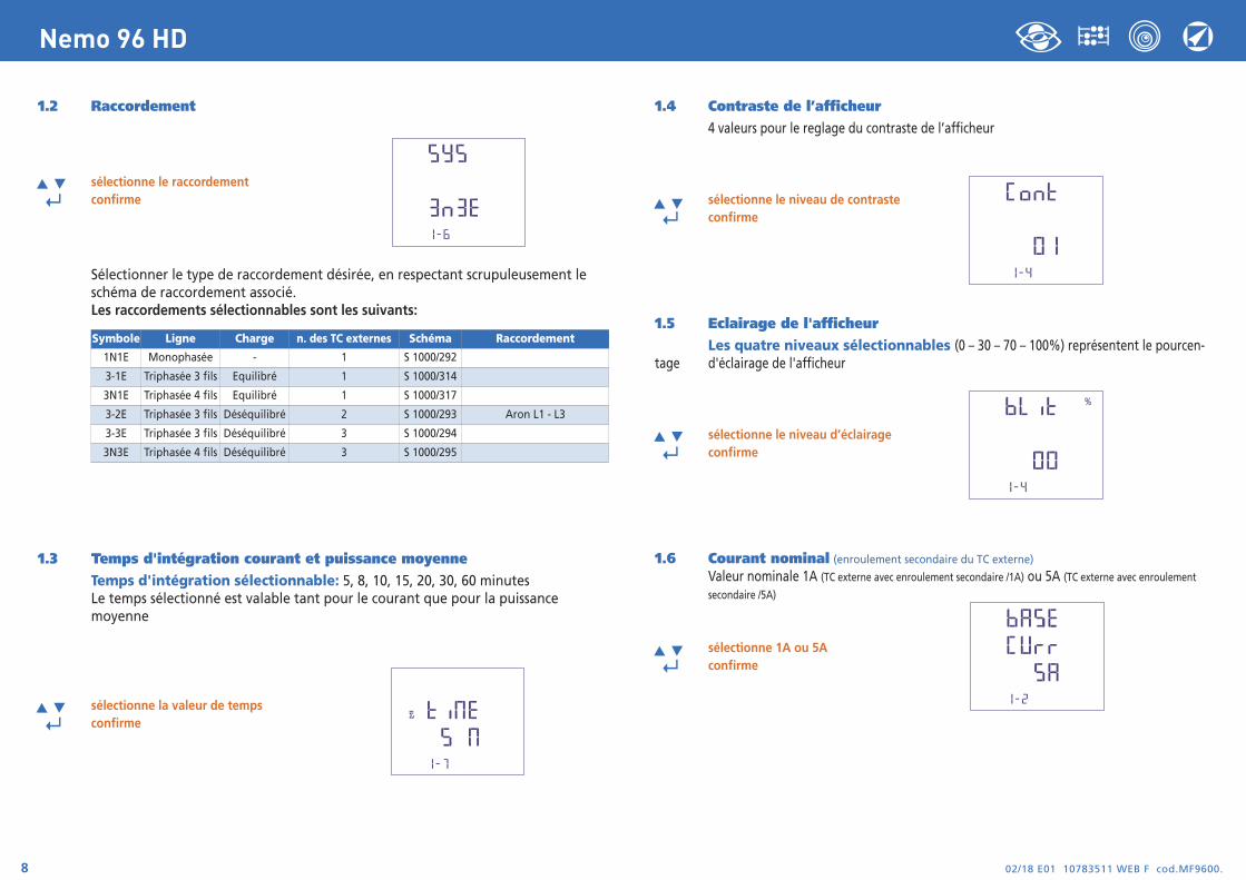
1.2 Raccordement
sélectionne le raccordement
↵ confirme
Sélectionner le type de raccordement désirée, en respectant scrupuleusement le schéma de raccordement associé. Les raccordements sélectionnables sont les suivants:
1.3 Temps d'intégration courant et puissance moyenneTemps d'intégration sélectionnable: 5, 8, 10, 15, 20, 30, 60 minutesLe temps sélectionné est valable tant pour le courant que pour la puissance moyenne
sélectionne la valeur de temps
↵ confirme
1.4 Contraste de l’afficheur4 valeurs pour le reglage du contraste de l’afficheur
sélectionne le niveau de contraste
↵ confirme
1.5 Eclairage de l'afficheurLes quatre niveaux sélectionnables (0 – 30 – 70 – 100%) représentent le pourcen-
tage d'éclairage de l'afficheur
sélectionne le niveau d’éclairage
↵ confirme
1.6 Courant nominal (enroulement secondaire du TC externe)
Valeur nominale 1A (TC externe avec enroulement secondaire /1A) ou 5A (TC externe avec enroulement
secondaire /5A)
sélectionne 1A ou 5A
↵ confirme
Symbole Ligne Charge n. des TC externes Schéma Raccordement
1N1E Monophasée - 1 S 1000/292
3-1E Triphasée 3 fils Equilibré 1 S 1000/314
3N1E Triphasée 4 fils Equilibré 1 S 1000/317
3-2E Triphasée 3 fils Déséquilibré 2 S 1000/293 Aron L1 - L3
3-3E Triphasée 3 fils Déséquilibré 3 S 1000/294
3N3E Triphasée 4 fils Déséquilibré 3 S 1000/295
02/18 E01 10783511 WEB F cod.MF9600. 9
Nemo 96 HD
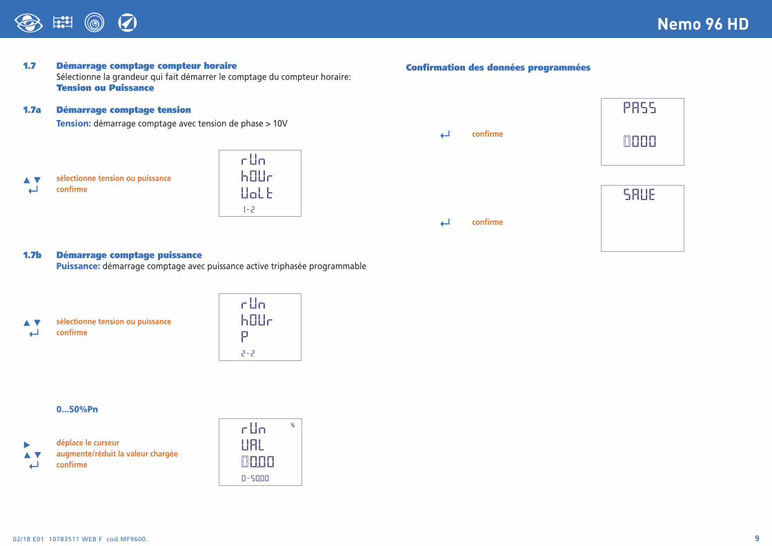
Confirmation des données programmées
↵ confirme
↵ confirme
1.7 Démarrage comptage compteur horaireSélectionne la grandeur qui fait démarrer le comptage du compteur horaire:Tension ou Puissance
1.7a Démarrage comptage tensionTension: démarrage comptage avec tension de phase > 10V
sélectionne tension ou puissance
↵ confirme
1.7b Démarrage comptage puissancePuissance: démarrage comptage avec puissance active triphasée programmable
sélectionne tension ou puissance ↵ confirme
0...50%Pn
déplace le curseur augmente/réduit la valeur chargée ↵ confirme
02/18 E01 10783511 WEB F cod.MF9600.10
Nemo 96 HD
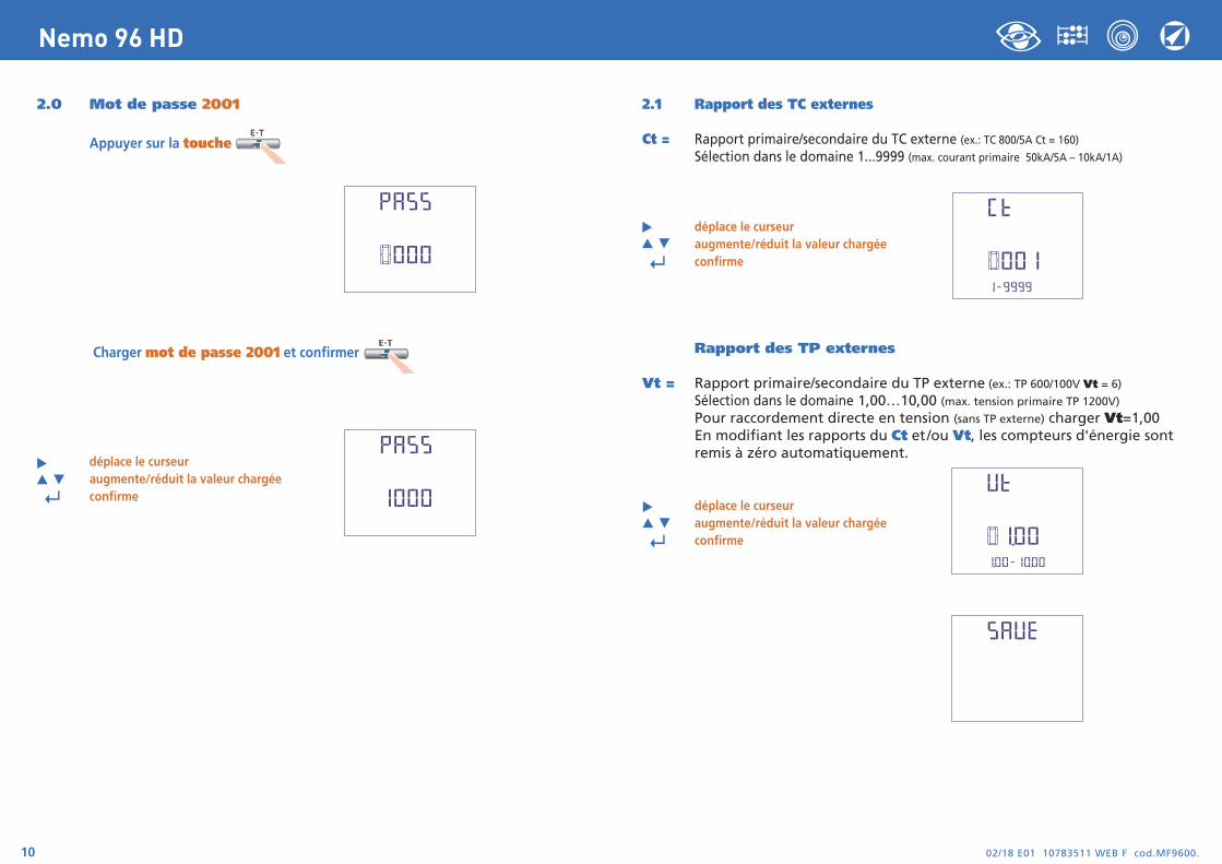
2.0 Mot de passe 2001
Appuyer sur la touche
Charger mot de passe 2001 et confirmer
déplace le curseuraugmente/réduit la valeur chargée
↵ confirme
2.1 Rapport des TC externes
Ct = Rapport primaire/secondaire du TC externe (ex.: TC 800/5A Ct = 160)Sélection dans le domaine 1...9999 (max. courant primaire 50kA/5A – 10kA/1A)
déplace le curseuraugmente/réduit la valeur chargée
↵ confirme
Rapport des TP externes
Vt = Rapport primaire/secondaire du TP externe (ex.: TP 600/100V Vt = 6)
Sélection dans le domaine 1,00…10,00 (max. tension primaire TP 1200V)
Pour raccordement directe en tension (sans TP externe) charger Vt=1,00 En modifiant les rapports du Ct et/ou Vt, les compteurs d'énergie sont remis à zéro automatiquement.
déplace le curseuraugmente/réduit la valeur chargée
↵ confirme
02/18 E01 10783511 WEB F cod.MF9600. 11
Nemo 96 HD
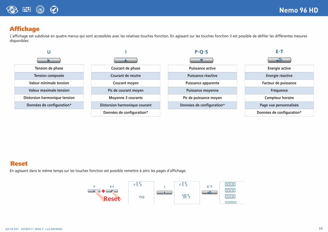
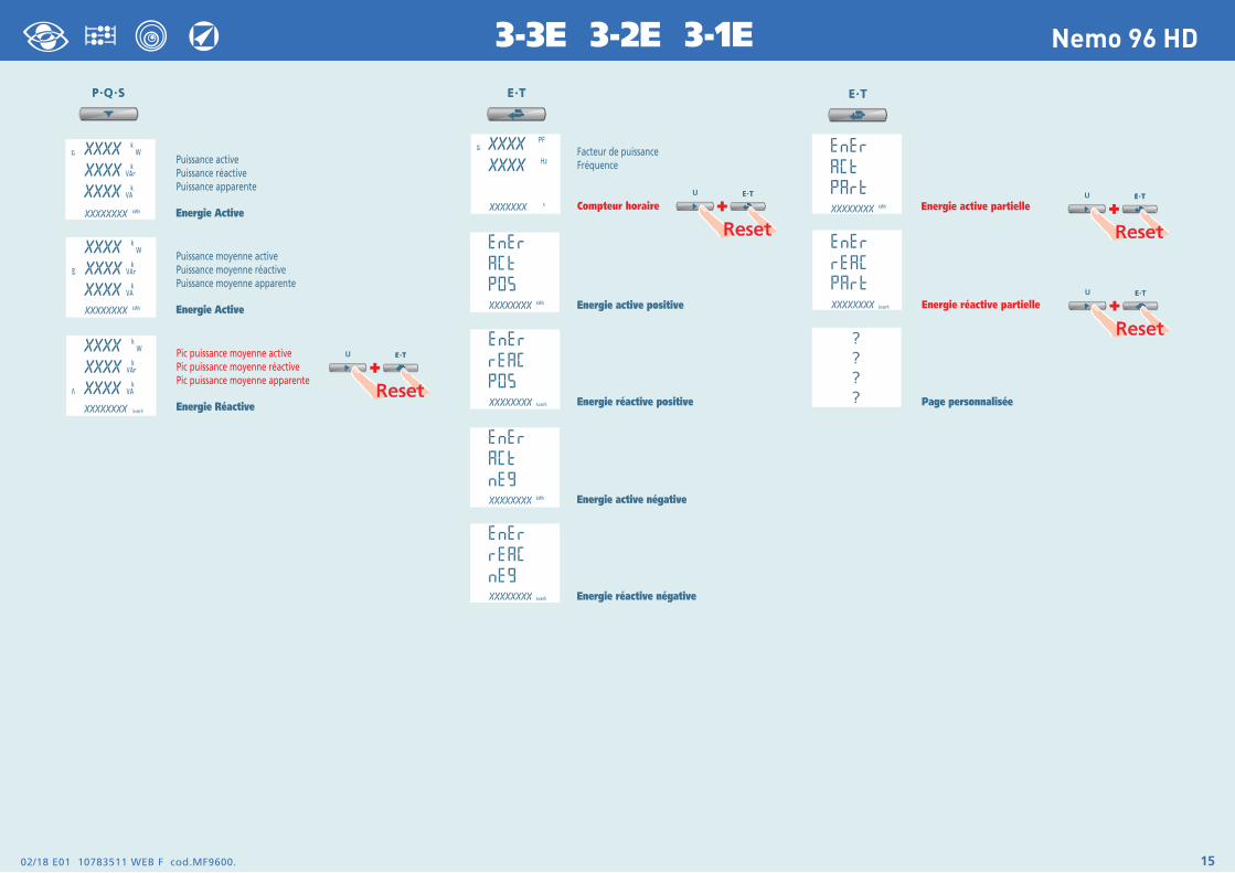
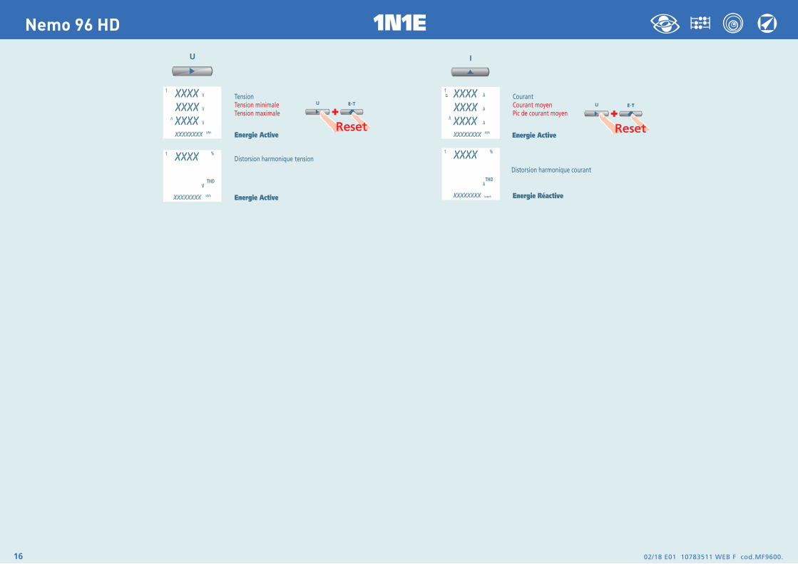
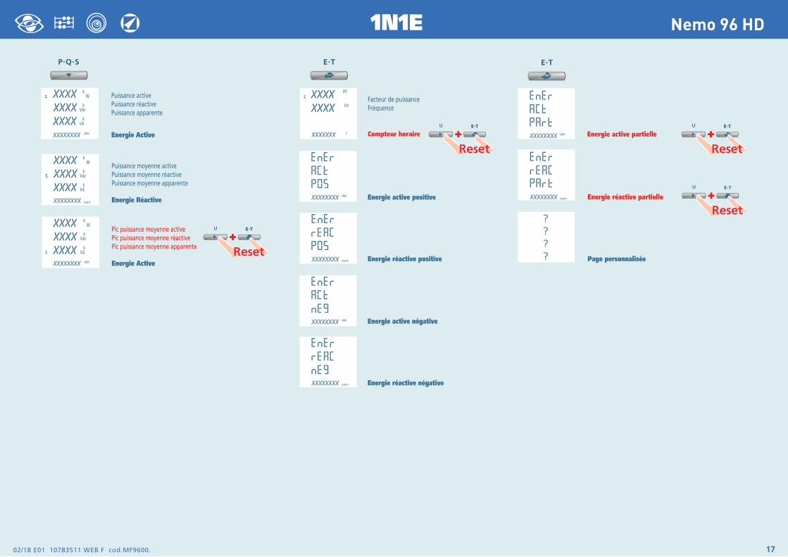
AffichageL'affichage est subdivisé en quatre menus qui sont accessibles avec les relatives touches fonction. En agissant sur les touches fonction il est possible de défiler les différentes mesures disponibles:
ResetEn agissant dans le même temps sur les touches fonction est possible remettre à zéro les pages d’affichage:
Tension de phase
Tension composée
Valeur minimale tension
Valeur maximale tension
Distorsion harmonique tension
Données de configuration*
Courant de phase
Courant de neutre
Courant moyen
Pic de courant moyen
Moyenne 3 courants
Distorsion harmonique courant
Données de configuration*
Puissance active
Puissance réactive
Puissance apparente
Puissance moyenne
Pic de puissance moyen
Données de configuration*
Energie active
Energie réactive
Facteur de puissance
Fréquence
Compteur horaire
Page vue personnalisée
Données de configuration*
+

02/18 E01 10783511 WEB F cod.MF9600.12
Nemo 96 HD 3N3E - 3N1E

02/18 E01 10783511 WEB F cod.MF9600. 13
Nemo 96 HD3N3E - 3N1E
02/18 E01 10783511 WEB F cod.MF9600.14
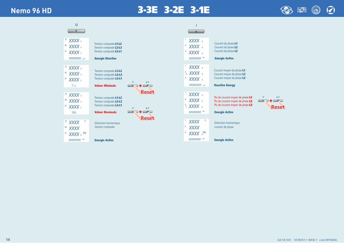
Nemo 96 HD 3-3E 3-2E 3-1E
02/18 E01 10783511 WEB F cod.MF9600. 15
Nemo 96 HD3-3E 3-2E 3-1E
02/18 E01 10783511 WEB F cod.MF9600.16
Nemo 96 HD 1N1E
02/18 E01 10783511 WEB F cod.MF9600. 17
Nemo 96 HD1N1E
02/18 E01 10783511 WEB F cod.MF9600.18
Nemo 96 HD
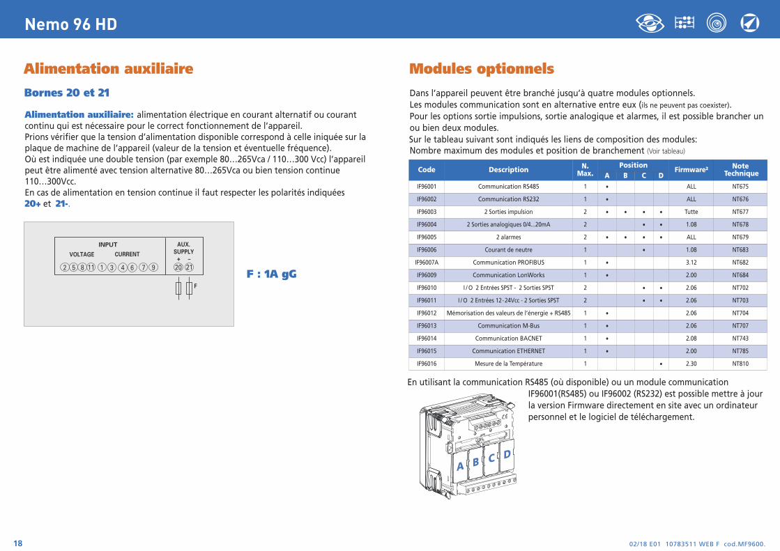
Alimentation auxiliaire
Bornes 20 et 21
Alimentation auxiliaire: alimentation électrique en courant alternatif ou courant continu qui est nécessaire pour le correct fonctionnement de l’appareil.Prions vérifier que la tension d’alimentation disponible correspond à celle iniquée sur la plaque de machine de l’appareil (valeur de la tension et éventuelle fréquence).Où est indiquée une double tension (par exemple 80…265Vca / 110…300 Vcc) l’appareil peut être alimenté avec tension alternative 80…265Vca ou bien tension continue 110…300Vcc. En cas de alimentation en tension continue il faut respecter les polarités indiquées20+ et 21-.
F : 1A gG
INPUT
VOLTAGE CURRENT
2 5 8 1 3 6 94 711 20
AUX.SUPPLY
21+ –
F
Modules optionnels
Dans l’appareil peuvent être branché jusqu’à quatre modules optionnels.Les modules communication sont en alternative entre eux (ils ne peuvent pas coexister).Pour les options sortie impulsions, sortie analogique et alarmes, il est possible brancher un ou bien deux modules.Sur le tableau suivant sont indiqués les liens de composition des modules:Nombre maximum des modules et position de branchement (Voir tableau)
En utilisant la communication RS485 (où disponible) ou un module communicationIF96001(RS485) ou IF96002 (RS232) est possible mettre à jourla version Firmware directement en site avec un ordinateurpersonnel et le logiciel de téléchargement.
A B C D
Code Description N.Max.
PositionFirmware2 Note
TechniqueA B C DIF96001 Communication RS485 1 • ALL NT675
IF96002 Communication RS232 1 • ALL NT676
IF96003 2 Sorties impulsion 2 • • • • Tutte NT677
IF96004 2 Sorties analogiques 0/4...20mA 2 • • 1.08 NT678
IF96005 2 alarmes 2 • • • • ALL NT679
IF96006 Courant de neutre 1 • 1.08 NT683
IF96007A Communication PROFIBUS 1 • 3.12 NT682
IF96009 Communication LonWorks 1 • 2.00 NT684
IF96010 I / O 2 Entrées SPST - 2 Sorties SPST 2 • • 2.06 NT702
IF96011 I / O 2 Entrées 12-24Vcc - 2 Sorties SPST 2 • • 2.06 NT703
IF96012 Mémorisation des valeurs de l’énergie + RS485 1 • 2.06 NT704
IF96013 Communication M-Bus 1 • 2.06 NT707
IF96014 Communication BACNET 1 • 2.08 NT743
IF96015 Communication ETHERNET 1 • 2.00 NT785
IF96016 Mesure de la Température 1 • 2.30 NT810

Insertion modules optionnelsEteindre l’appareilBrancher le module optionnel Alimenter l’appareil et attendre quelque seconde pour la reconnaissance du module Pour la programmation des paramètres de chaque module, prions se référer au manuel correspondant.
3.0 Mot de passe 3002Protocole CommunicationPour les modules communication (voir tableau) il faut charger le Protocol CommunicationCharger le mot de passe 3002 et sélectionner le protocole de communication (Voir tableau).
* Pour les details, prions voir le protocole de communication
02/18 E01 10783511 WEB F cod.MF9600. 19
Nemo 96 HD
IF96001RS485
IF96002RS232
IF96007APROFIBUS
IF96009LonWorks
IF96012Memoria
IF96013M-Bus
IF96014Bacnet
IF96015Ethernet
PROTOCOLEMdbS
MtCP
MdbS
MtCP
MdbS
MtCP
MdbS
MtCP
MdbS
MtCP
Mbus*
Mb 2*bACn
MdbS
MtCP
ATTENTION!L’insertion des modules doit être faite avec l’instrument non alimenté.
1
2
02/18 E01 10783511 WEB F cod.MF9600.20
Nemo 96 HD
Configuration d’usine
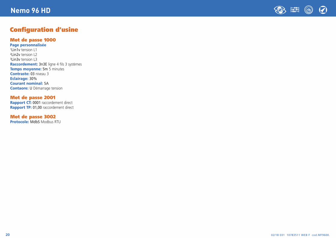
Mot de passe 1000Page personnalisée1Lin1v tension L12Lin2v tension L23Lin3v tension L3Raccordement: 3n3E ligne 4 fils 3 systèmes Temps moyenne: 5m 5 minutesContraste: 03 niveau 3Eclairage: 30%Courant nominal: 5AContaore: U Démarrage tension
Mot de passe 2001Rapport CT: 0001 raccordement directRapport TP: 01,00 raccordement direct
Mot de passe 3002Protocole: MdbS Modbus RTU
Via Travaglia 7 20094 CORSICO (MI) Tel. 02 44 878.1 Fax 02 45 03 448 +39 02 45 86 76 63 [email protected]
www.imeitaly.com
02/1
8 E
01 1
0783
511
WEB
D
cod.
MF9
600.
Nemo 96 HD
02/18 E01 10783511 WEB D cod.MF9600.2
Nemo 96 HD
IndexAnschlußbild Seite 3
Installationsanweisungen Seite 3
Programmierung Seiten 4-5
Phasenfolgediagnostik Seite 5
Stufe 1 Kennwort 1000 Seiten 6-9
Sfufe 2 Kennwort 2001 Seite 10
Stufe 3 Kennwort 3002 Seite 19
Anzeige Seite 11
Reset Seite 11
Dreiphasen-4 Leiter Seiten 12-13
Dreiphasen-3 Leiter Seiten 14-15
Einphasen Seiten 16-17
Hilfsspannung Seite 18
Wahlmodule Seite 18
Einsetzen der Wahlmodule Seite 19
Werkeinstellungen Seite 20
MultimessungSie messen und zeigenverschiedene Größengleichzeitig an
EnergiezählenSie quantifizieren denEnergieverbrauch
KommunikationSie teilen dieFernmessungen mitSie verbinden überSchnittstelleverschiedenenKommunicationsmodus
Messung undKontrolleSie messen und greifenein, um besondereBedingungen zumelden
I.M.E
. S.p.
A. be
hält s
ich da
s Rec
ht vo
r, die
techn
ische
Merk
male
ohne
Ben
achri
chtig
ung z
u änd
ern
Die technische Unterlagen für das Produkt ist auf der Site www.imeitaly.com in dem Raum “Documentazione tecnica” verfügbar. Tippen in dem Feld “Codice Nota Tecnica: NT680”ein.

02/18 E01 10783511 WEB D cod.MF9600. 3
Nemo 96 HD
ACHTUNG!Verbinden die Hilfsspannung mit Klemmen 20 und 21
Anschlußbild
F : 1A gG
InstallationsanweisungenDer Einbau dieses Gerätes muss nur von Fachkräftenausgeführt. Bevor das Gerät eingebaut wird, muss das Typenschild(Mess-Spannung, Mess-Strom, Hilfsspannung, Frequenz) mit dentatsächlichen Netzgegebenheiten verglichen werden.Der Anschluss erfolgt gem. Anschlussbilder. Falschanschlussführt zu erheblichen Anzeigefehlern! Es können sogar Beschädigungen auftreten.
Wenn das Gerät angeschlossen ist, ergänzen dieInstallation mit der Gerätskonfiguration.
X
XX
S1
P1
S1
P1
a
A
b
B
a
A
b
BL1
L2
L3
LOAD
2 5 8
INPUT
VOLTAGE CURRENT
20
AUX.SUPPLY
21+ –
2 5 8 1 3 6 94 711
F
2 5 8 111 3 6 94 7
S1
P1
a
A
b
BL
NLOADX
20
AUX.SUPPLY
2121+ –
2 11
INPUT
VOLTAGE CURRENT
F
X
XX
S1
P1 S1
P1 S1
P1
a
A
b
B
a
A
b
BL1
L2
L3
LOAD
2 5 8
INPUT
VOLTAGE CURRENT
20
AUX.SUPPLY
21+ –
2 5 8 1 3 6 94 711
F
S 1000/2921N1E
S 1000/2933-2E
S 1000/2943-3E
X
XX
S1
P1
a
A
b
B
a
A
b
BL1
L2
L3
LOAD
2 5 8
INPUT
VOLTAGE CURRENT
20
AUX.SUPPLY
21+ –
2 5 8 1 3 6 94 711
F
S 1000/3143-1E
X
XX
S1
P1 S1
P1 S1
P1
a
AL1
L2
L3
NX X X
LOAD
INPUT
VOLTAGE CURRENT
20
AUX.SUPPLY
21+ –
2 5 8 1 3 6 94 711
2 5 8 11F
S 1000/2953N3E
X
XX
S1
P1
a
A
X X X
LOAD
INPUT
VOLTAGE CURRENT
20
AUX.SUPPLY
2121+ –
2 5 8 1 3 6 94 711
2 5 8 11
L1
L2
L3
N
F
S 1000/3173N1E
ProgrammierungDas Menü ist auf zwei Stufen, mit 3 verschiedenen numerischen Kennworten geschützt.Die Programmierung wird durch Fronttastatur Berührungsbildschirm, 4 Tastengemacht
Rückt den Cursor
Erhöht den eingestellten WertIn der Seiten mit Auswahl unter festen Werten, blättert es die einstellbaren Werten.
Sinkt den eingestellten WertIn der Seiten mit Auswahl unter festen Werten, blättert es die einstellbaren Werten.
Bestätigt
Während der Programmierung halten Sie 2 Tasten gleichzeitig gedrückt um
Zurückzukehren
Ein- und Austritt ohne Speicherung
Stufe 1 Kennwort = 10001.0 Kennwort1.1 Kundespezifische Anzeigeseite1.2 Anschluss1.3 Stromintegrationszeit und mittlere Leistung1.4 Anzeigekontrast1.5 Hintergrundbeleuchtung der Anzeige1.6 Nennstrom1.7 Zählungsstart des Betriebsstundenzählers
Stufe 2 Kennwort = 20012.0 Kennwort2.1 Externe CT und VT-Verhältnis
Stufe 3 Kennwort = 30023.0 Kommunikationsprotokoll
02/18 E01 10783511 WEB D cod.MF9600.4
Nemo 96 HD
Programmierbare Parameter
Stufe 1 Kennwort = 10001.1 Kundespezifische Anzeigeseite
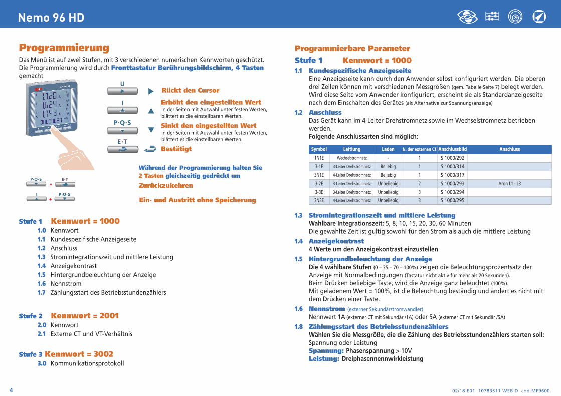
Eine Anzeigeseite kann durch den Anwender selbst konfiguriert werden. Die oberen drei Zeilen können mit verschiedenen Messgrößen (gem. Tabelle Seite 7) belegt werden.Wird diese Seite vom Anwender konfiguriert, erscheint sie als Standardanzeigeseite nach dem Einschalten des Gerätes (als Alternative zur Spannungsanzeige)
1.2 AnschlussDas Gerät kann im 4-Leiter Drehstromnetz sowie im Wechselstromnetz betrieben werden. Folgende Anschlussarten sind möglich:
1.3 Stromintegrationszeit und mittlere LeistungWahlbare Integrationszeit: 5, 8, 10, 15, 20, 30, 60 MinutenDie gewahlte Zeit ist gultig sowohl für den Strom als auch die mittlere Leistung
1.4 Anzeigekontrast 4 Werte um den Anzeigekontrast einzustellen
1.5 Hintergrundbeleuchtung der AnzeigeDie 4 wählbare Stufen (0 – 35 – 70 – 100%) zeigen die Beleuchtungsprozentsatz der Anzeige mit Normalbedingungen (Tastatur nicht aktiv für mehr als 20 Sekunden).Beim Drücken beliebige Taste, wird die Anzeige ganz beleuchtet (100%).Mit geladenem Wert = 100%, ist die Beleuchtung beständig und ändert es nicht mit dem Drücken einer Taste.
1.6 Nennstrom (externer Sekundärstromwandler)
Nennwert 1A (externer CT mit Sekundär /1A) oder 5A (externer CT mit Sekundär /5A)
1.8 Zählungsstart des BetriebsstundenzählersWählen Sie die Messgröße, die die Zählung des Betriebsstundenzählers starten soll: Spannung oder Leistung Spannung: Phasenspannung > 10VLeistung: Dreiphasennennwirkleistung
Symbol Leitiung Laden N. der externen CT Anschlussbild Anschluss
1N1E Wechselstromnetz - 1 S 1000/292
3-1E 3-Leiter Drehstromnetz Beliebig 1 S 1000/314
3N1E 4-Leiter Drehstromnetz Beliebig 1 S 1000/317
3-2E 3-Leiter Drehstromnetz Unbeliebig 2 S 1000/293 Aron L1 - L3
3-3E 3-Leiter Drehstromnetz Unbeliebig 3 S 1000/294
3N3E 4-Leiter Drehstromnetz Unbeliebig 3 S 1000/295
02/18 E01 10783511 WEB D cod.MF9600. 5
Nemo 96 HD
Programmierbarer Wert : 0...50%PnPn = Dreiphasennennwirkleistung = Nenndrehspannung Un x Nennstrom In x√3Un: 400VIn: 1A oder 5APn = 400V x5A x √3= 3464W oder 400V x1A x√3= 692,8W
Stufe 2 Kennwort = 20012.1 Externe CT und VT ÜbersetzungCt = Primär/Sekundärverhältnis des externen CT Wandler (z.B CT 800/5A Ct = 160)
Auswahl im Feld 1...9999 (höchste Primärstrom 50kA/5A - 10kA/1A)
Vt =Primär/Sekundärverhältnis des externen VT Wandler (z.B. VT 600/100V Vt = 6)
Auswahl im Feld 1,00...10,00 00 (höchste Primärspannung TV 1200V)
Für direkten Spannungsanschluss (ohne externer VT Wandler) stellen Vt=1,00 ein.Bei Veränderung von Ct und/oder Vt werden automatisch dieZählerstände auf Null zurückgesetzt.
Stufe 3 Kennwort = 30023.0 Kommunikationsprotokoll (siehe Punkt 3 Seite19).
PhasenfolgediagnostikIn der Software der Vorrichtung gibt es einen Diagnostik- und Reparaturalgorithmus derVoltmeter- und Strommessereinschaltungsfolge eingeführt. Auf Wunsch kann diese Funktion durch ein Kennwort betätigt sein. Durch die Softwaregestattet es die Verdrahtungsfolge anzuzeigen und zu ändern, unter der Bedingung,dass die folgende Bedingungen beachtet werden:
1) Der Null-Leiter (in dem 4-Leiter Netz) an der entsprechenden Klemme richtig angeschlossen ist(normalweise Klemme n. 11).
2) Gibt es kein Kabelkreuz zwischen verschiedenen Stromwandlern (z.B. auf der Phase 1 der Vorrichtung gibt es einen Kabel, den aus dem Stromwandler 1 kommt, und auf dem anderen einen Kabel des
Stromwandler 2).
3) Der Leistungsfaktor für jede Phase zwischen 1 und 0,5 induktive Belastung eingeschlossenist. Siehe www.imeitaly.com “TECHNICAL SUPPORT”.
02/18 E01 10783511 WEB D cod.MF9600.6
Nemo 96 HD
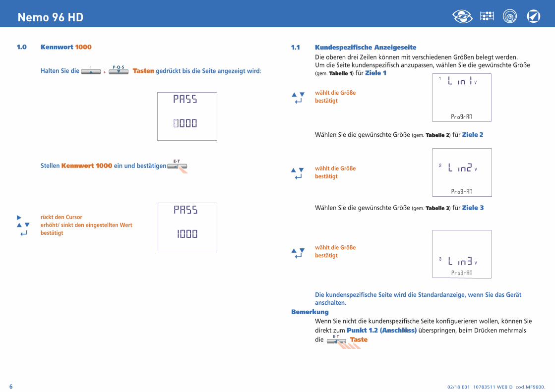
1.0 Kennwort 1000
Halten Sie die Tasten gedrückt bis die Seite angezeigt wird:
Stellen Kennwort 1000 ein und bestätigen
rückt den Cursorerhöht/ sinkt den eingestellten Wert
↵ bestätigt
1.1 Kundespezifische AnzeigeseiteDie oberen drei Zeilen können mit verschiedenen Größen belegt werden. Um die Seite kundenspezifisch anzupassen, wählen Sie die gewünschte Größe (gem. Tabelle 1) für Ziele 1
wählt die Größe
↵ bestätigt
Wählen Sie die gewünschte Größe (gem. Tabelle 2) für Ziele 2
wählt die Größe
↵ bestätigt
Wählen Sie die gewünschte Größe (gem. Tabelle 3) für Ziele 3
wählt die Größe
↵ bestätigt
Die kundenspezifische Seite wird die Standardanzeige, wenn Sie das Gerät anschalten.
BemerkungWenn Sie nicht die kundenspezifische Seite konfiguerieren wollen, können Sie direkt zum Punkt 1.2 (Anschlüss) überspringen, beim Drücken mehrmals die Taste
02/18 E01 10783511 WEB D cod.MF9600. 7
Nemo 96 HD
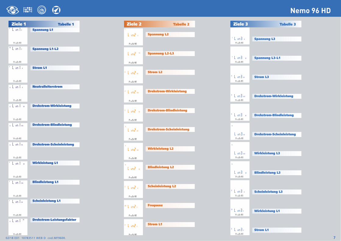
Ziele 1 Tabelle 1Spannung L1
Spannung L2
Ziele 2 Tabelle 2 Ziele 3 Tabelle 3
Spannung L3
Spannung L1-L2
Strom L1
Drehstrom-Wirkleistung
Drehstrom-Blindleistung
Drehstrom-Scheinleistung
Wirkleistung L1
Blindleistung L1
Scheinleistung L1
Drehstrom-Leistungsfaktor
Spannung L2-L3
Strom L2
Drehstrom-Wirkleistung
Drehstrom-Blindleistung
Drehstrom-Scheinleistung
Wirkleistung L2
Blindleistung L2
Scheinleistung L2
Frequenz
Strom L1
Spannung L3-L1
Strom L3
Drehstrom-Wirkleistung
Drehstrom-Blindleistung
Drehstrom-Scheinleistung
Wirkleistung L3
Blindleistung L3
Scheinleistung L3
Wirkleistung L1
Strom L1
Neutralleiterstrom
02/18 E01 10783511 WEB D cod.MF9600.8
Nemo 96 HD
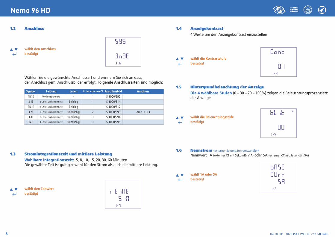
1.2 Anschluss
wählt den Anschluss
↵ bestätigt
Wählen Sie die gewünschte Anschlussart und erinnern Sie sich an dass, der Anschluss gem. Anschlussbilder erfolgt. Folgende Anschlussarten sind möglich:
1.3 Stromintegrationszeit und mittlere LeistungWahlbare Integrationszeit: 5, 8, 10, 15, 20, 30, 60 MinutenDie gewählte Zeit ist gultig sowohl für den Strom als auch die mittlere Leistung.
wählt den Zeitwert
↵ bestätigt
1.4 Anzeigekontrast 4 Werte um den Anzeigekontrast einzustellen
wählt die Kontraststufe
↵ bestätigt
1.5 Hintergrundbeleuchtung der AnzeigeDie 4 wählbare Stufen (0 – 30 – 70 – 100%) zeigen die Beleuchtungsprozentsatzder Anzeige
wählt die Beleuchtungsstufe
↵ bestätigt
1.6 Nennstrom (externer Sekundärstromwandler)
Nennwert 1A (externer CT mit Sekundär /1A) oder 5A (externer CT mit Sekundär /5A)
wählt 1A oder 5A
↵ bestätigt
Symbol Leitiung Laden N. der externen CT Anschlussbild Anschluss
1N1E Wechselstromnetz - 1 S 1000/292
3-1E 3-Leiter Drehstromnetz Beliebig 1 S 1000/314
3N1E 4-Leiter Drehstromnetz Beliebig 1 S 1000/317
3-2E 3-Leiter Drehstromnetz Unbeliebig 2 S 1000/293 Aron L1 - L3
3-3E 3-Leiter Drehstromnetz Unbeliebig 3 S 1000/294
3N3E 4-Leiter Drehstromnetz Unbeliebig 3 S 1000/295
02/18 E01 10783511 WEB D cod.MF9600. 9
Nemo 96 HD
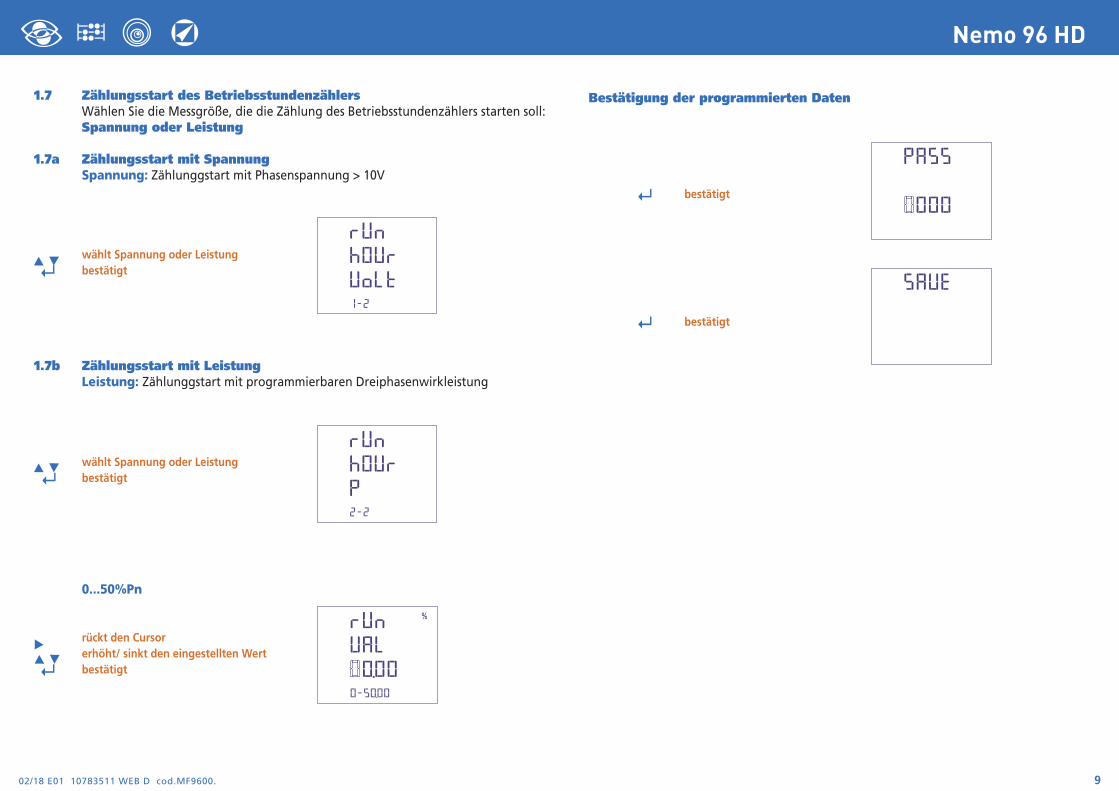
Bestätigung der programmierten Daten
↵ bestätigt
↵ bestätigt
1.7 Zählungsstart des BetriebsstundenzählersWählen Sie die Messgröße, die die Zählung des Betriebsstundenzählers starten soll:Spannung oder Leistung
1.7a Zählungsstart mit SpannungSpannung: Zählunggstart mit Phasenspannung > 10V
wählt Spannung oder Leistung
↵ bestätigt
1.7b Zählungsstart mit LeistungLeistung: Zählunggstart mit programmierbaren Dreiphasenwirkleistung
wählt Spannung oder Leistung ↵ bestätigt
0...50%Pn
rückt den Cursorerhöht/ sinkt den eingestellten Wert
↵ bestätigt
02/18 E01 10783511 WEB D cod.MF9600.10
Nemo 96 HD
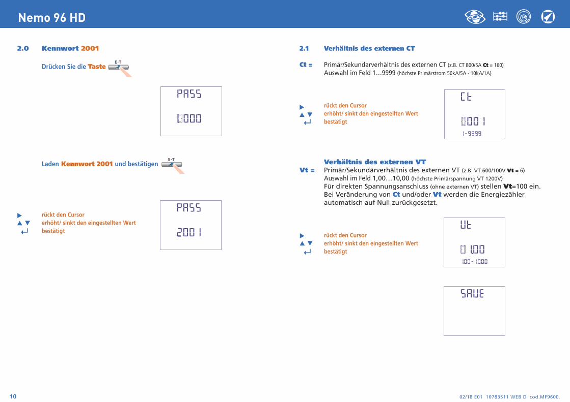
2.0 Kennwort 2001
Drücken Sie die Taste
Laden Kennwort 2001 und bestätigen
rückt den Cursorerhöht/ sinkt den eingestellten Wert
↵ bestätigt
2.1 Verhältnis des externen CT
Ct = Primär/Sekundarverhältnis des externen CT (z.B. CT 800/5A Ct = 160)
Auswahl im Feld 1…9999 (höchste Primärstrom 50kA/5A - 10kA/1A)
rückt den Cursorerhöht/ sinkt den eingestellten Wert
↵ bestätigt
Verhältnis des externen VTVt = Primär/Sekundärverhältnis des externen VT (z.B. VT 600/100V Vt = 6)
Auswahl im Feld 1,00…10,00 (höchste Primärspannung VT 1200V)
Für direkten Spannungsanschluss (ohne externen VT) stellen Vt=100 ein.Bei Veränderung von Ct und/oder Vt werden die Energiezählerautomatisch auf Null zurückgesetzt.
rückt den Cursorerhöht/ sinkt den eingestellten Wert
↵ bestätigt
02/18 E01 10783511 WEB D cod.MF9600. 11
Nemo 96 HD
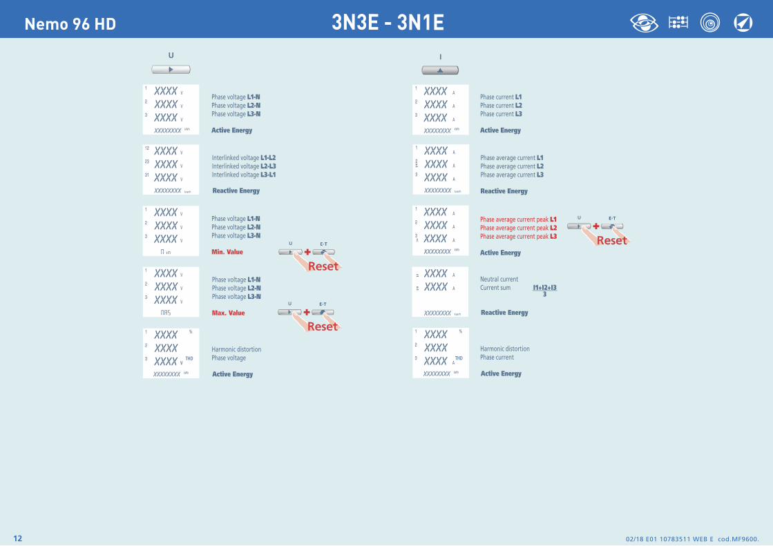
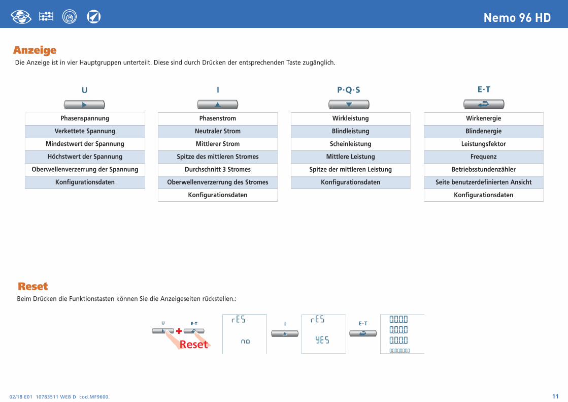
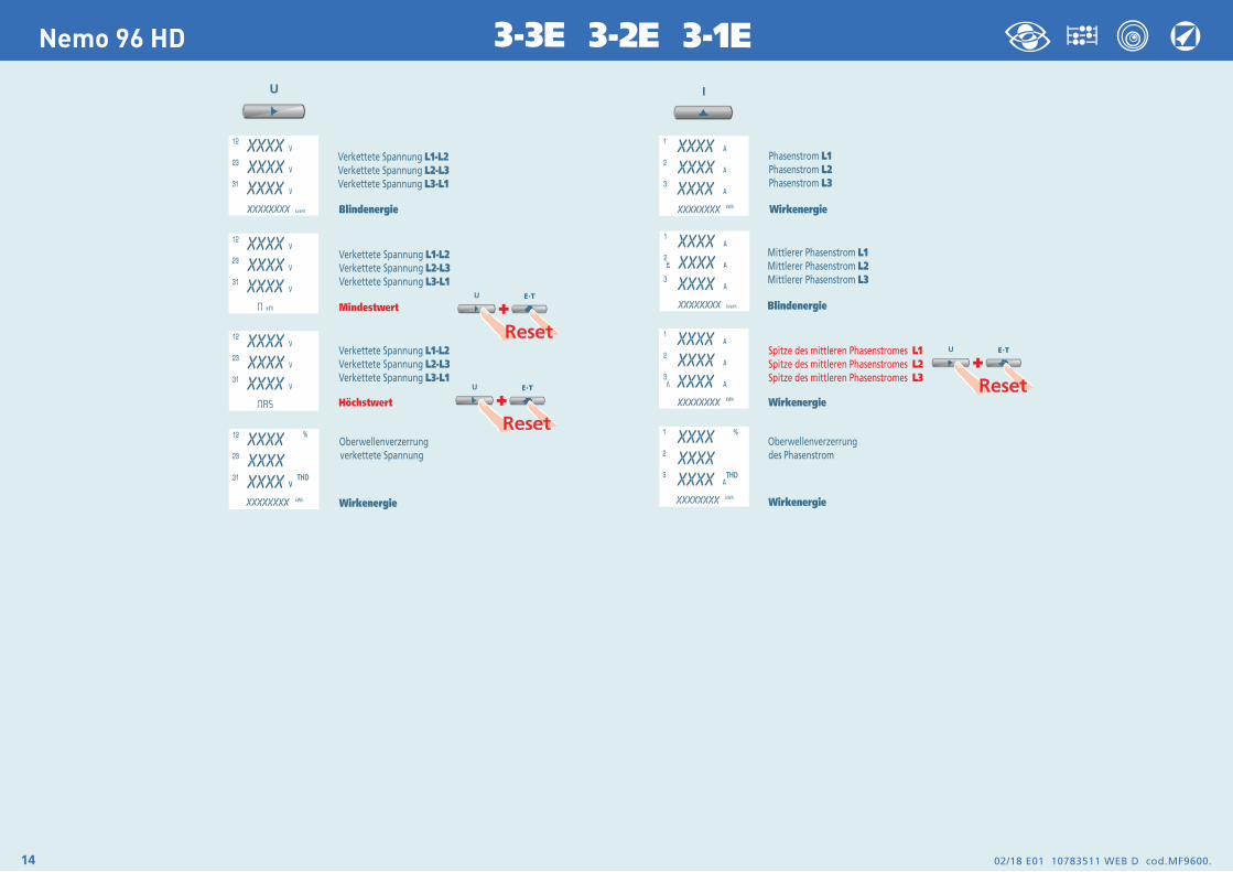
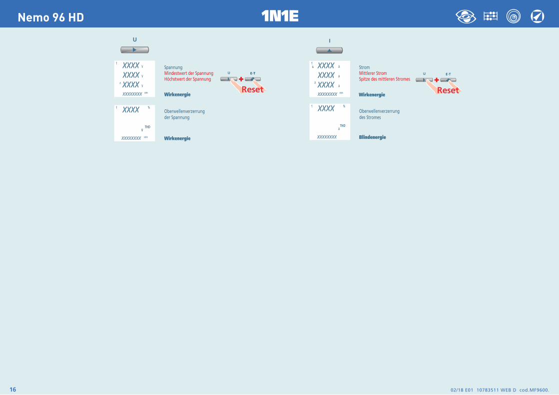
AnzeigeDie Anzeige ist in vier Hauptgruppen unterteilt. Diese sind durch Drücken der entsprechenden Taste zugänglich.
ResetBeim Drücken die Funktionstasten können Sie die Anzeigeseiten rückstellen.:
Phasenspannung
Verkettete Spannung
Mindestwert der Spannung
Höchstwert der Spannung
Oberwellenverzerrung der Spannung
Konfigurationsdaten
Phasenstrom
Neutraler Strom
Mittlerer Strom
Spitze des mittleren Stromes
Durchschnitt 3 Stromes
Oberwellenverzerrung des Stromes
Konfigurationsdaten
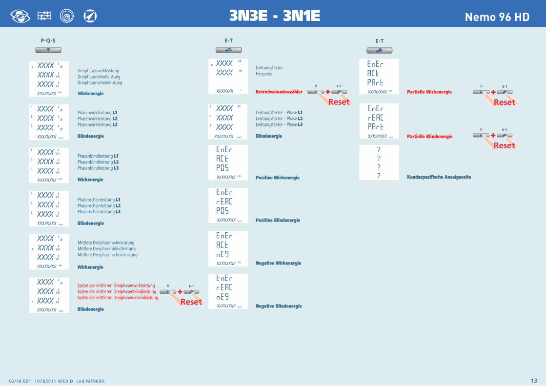
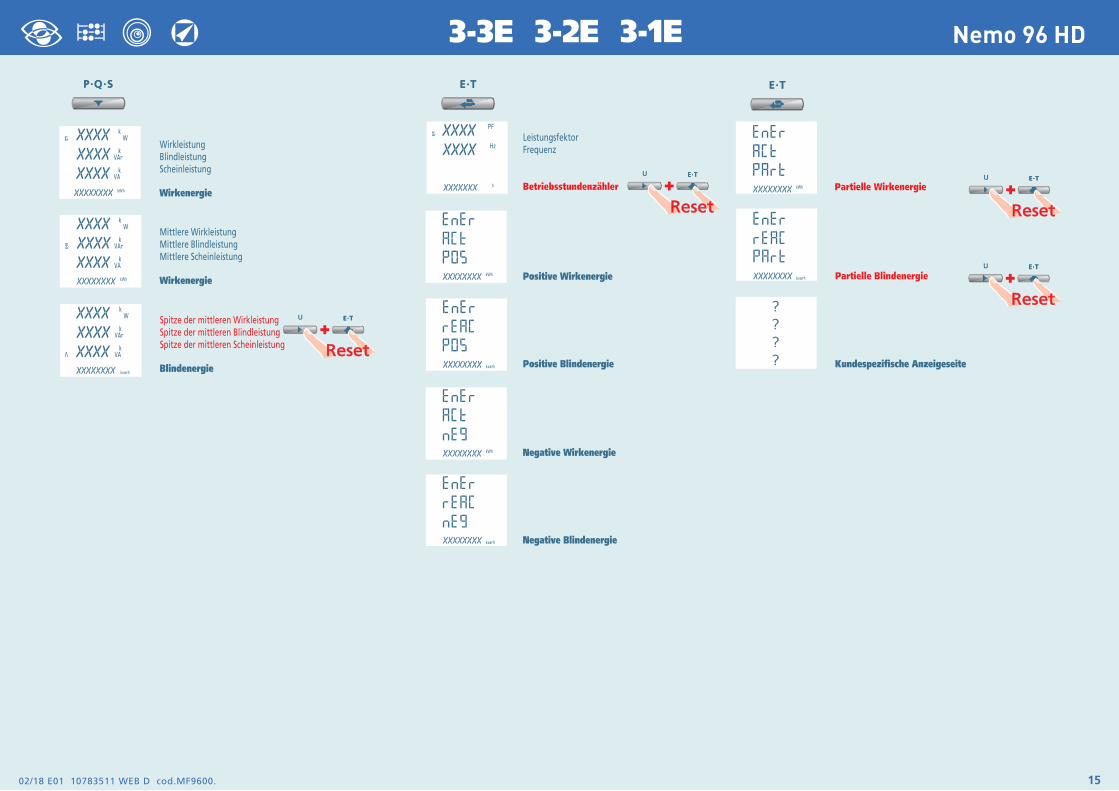
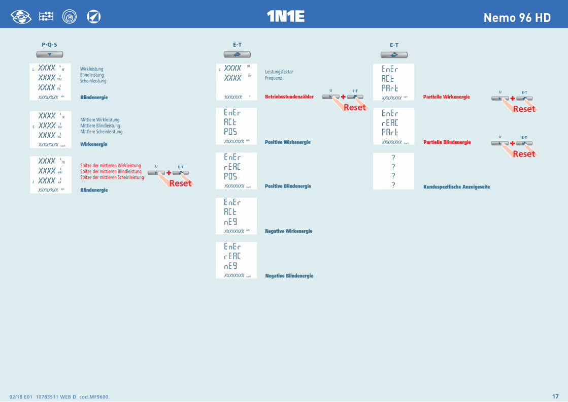
Wirkleistung
Blindleistung
Scheinleistung
Mittlere Leistung
Spitze der mittleren Leistung
Konfigurationsdaten
Wirkenergie
Blindenergie
Leistungsfektor
Frequenz
Betriebsstundenzähler
Seite benutzerdefinierten Ansicht
Konfigurationsdaten
+
02/18 E01 10783511 WEB D cod.MF9600. 13
Nemo 96 HD3N3E - 3N1E
02/18 E01 10783511 WEB D cod.MF9600.14
Nemo 96 HD 3-3E 3-2E 3-1E
02/18 E01 10783511 WEB D cod.MF9600. 15
Nemo 96 HD3-3E 3-2E 3-1E
02/18 E01 10783511 WEB D cod.MF9600.16
Nemo 96 HD 1N1E
02/18 E01 10783511 WEB D cod.MF9600. 17
Nemo 96 HD1N1E
02/18 E01 10783511 WEB D cod.MF9600.18
Nemo 96 HD
Hilfsspannung
Klemmen 20 und 21
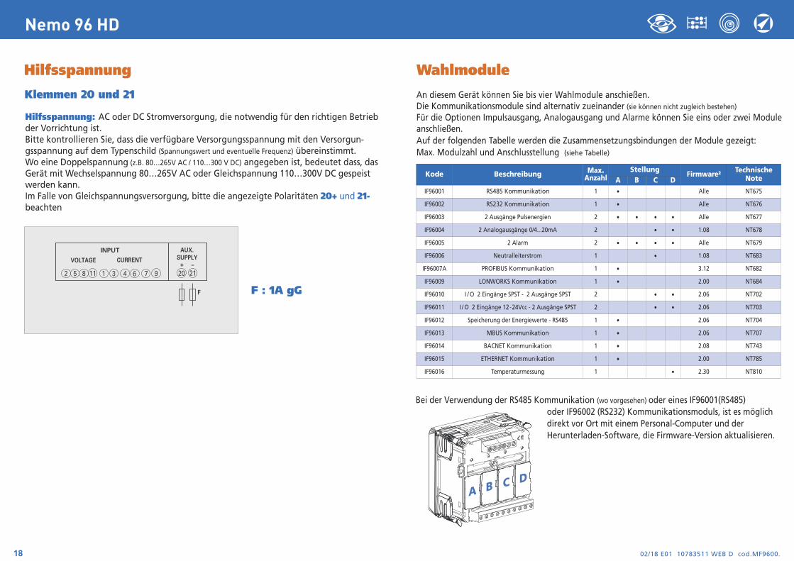
Hilfsspannung: AC oder DC Stromversorgung, die notwendig für den richtigen Betrieb der Vorrichtung ist.Bitte kontrollieren Sie, dass die verfügbare Versorgungsspannung mit den Versorgun- gsspannung auf dem Typenschild (Spannungswert und eventuelle Frequenz) übereinstimmt.Wo eine Doppelspannung (z.B. 80…265V AC / 110…300 V DC) angegeben ist, bedeutet dass, das Gerät mit Wechselspannung 80…265V AC oder Gleichspannung 110…300V DC gespeist werden kann. Im Falle von Gleichspannungsversorgung, bitte die angezeigte Polaritäten 20+ und 21-beachten
F : 1A gG
INPUT
VOLTAGE CURRENT
2 5 8 1 3 6 94 711 20
AUX.SUPPLY
21+ –
F
Wahlmodule
An diesem Gerät können Sie bis vier Wahlmodule anschießen.Die Kommunikationsmodule sind alternativ zueinander (sie können nicht zugleich bestehen)Für die Optionen Impulsausgang, Analogausgang und Alarme können Sie eins oder zwei Module anschließen. Auf der folgenden Tabelle werden die Zusammensetzungsbindungen der Module gezeigt:Max. Modulzahl und Anschlusstellung (siehe Tabelle)
Bei der Verwendung der RS485 Kommunikation (wo vorgesehen) oder eines IF96001(RS485) oder IF96002 (RS232) Kommunikationsmoduls, ist es möglich direkt vor Ort mit einem Personal-Computer und der Herunterladen-Software, die Firmware-Version aktualisieren.
A B C D
Kode Beschreibung Max.Anzahl
StellungFirmware2 Technische
NoteA B C DIF96001 RS485 Kommunikation 1 • Alle NT675
IF96002 RS232 Kommunikation 1 • Alle NT676
IF96003 2 Ausgänge Pulsenergien 2 • • • • Alle NT677
IF96004 2 Analogausgänge 0/4...20mA 2 • • 1.08 NT678
IF96005 2 Alarm 2 • • • • Alle NT679
IF96006 Neutralleiterstrom 1 • 1.08 NT683
IF96007A PROFIBUS Kommunikation 1 • 3.12 NT682
IF96009 LONWORKS Kommunikation 1 • 2.00 NT684
IF96010 I / O 2 Eingänge SPST - 2 Ausgänge SPST 2 • • 2.06 NT702
IF96011 I / O 2 Eingänge 12-24Vcc - 2 Ausgänge SPST 2 • • 2.06 NT703
IF96012 Speicherung der Energiewerte - RS485 1 • 2.06 NT704
IF96013 MBUS Kommunikation 1 • 2.06 NT707
IF96014 BACNET Kommunikation 1 • 2.08 NT743
IF96015 ETHERNET Kommunikation 1 • 2.00 NT785
IF96016 Temperaturmessung 1 • 2.30 NT810
02/18 E01 10783511 WEB D cod.MF9600. 19
Nemo 96 HD
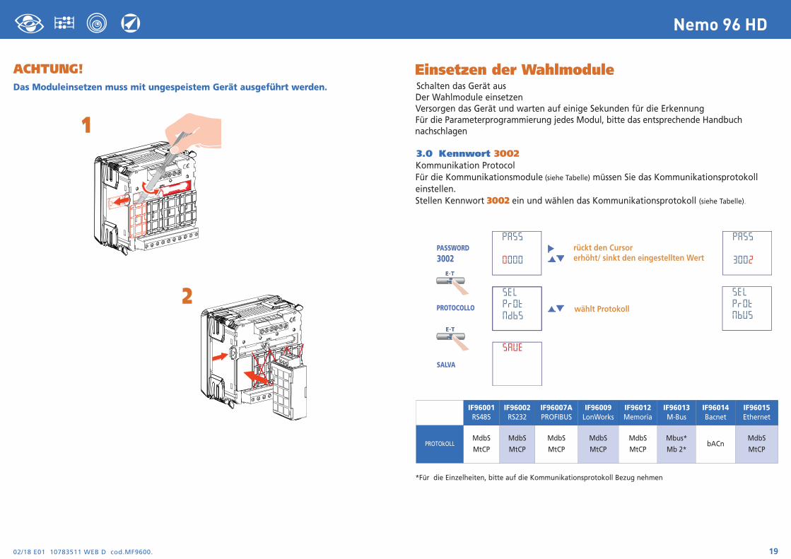
Einsetzen der WahlmoduleSchalten das Gerät ausDer Wahlmodule einsetzenVersorgen das Gerät und warten auf einige Sekunden für die ErkennungFür die Parameterprogrammierung jedes Modul, bitte das entsprechende Handbuch nachschlagen
3.0 Kennwort 3002Kommunikation ProtocolFür die Kommunikationsmodule (siehe Tabelle) müssen Sie das Kommunikationsprotokoll einstellen. Stellen Kennwort 3002 ein und wählen das Kommunikationsprotokoll (siehe Tabelle).
*Für die Einzelheiten, bitte auf die Kommunikationsprotokoll Bezug nehmen
IF96001RS485
IF96002RS232
IF96007APROFIBUS
IF96009LonWorks
IF96012Memoria
IF96013M-Bus
IF96014Bacnet
IF96015Ethernet
PROTOkOLLMdbS
MtCP
MdbS
MtCP
MdbS
MtCP
MdbS
MtCP
MdbS
MtCP
Mbus*
Mb 2*bACn
MdbS
MtCP
ACHTUNG!Das Moduleinsetzen muss mit ungespeistem Gerät ausgeführt werden.
1
2
02/18 E01 10783511 WEB D cod.MF9600.20
Nemo 96 HD
Werkeinstellung
Kennwort 1000Kundespezifische Anzeigeseite1Lin1v Spannung L12Lin2v Spannung L23Lin3v Spannung L3Anschluss: 3n3E vierfädig 3 Systeme LeitungMittlere Zeit: 5m 5 MinuteContrast: 03 Stufe 3Hintergrundbeleuchtung: 30%Nennstrom: 5ABetriebsstundenzähler: U Spannungsstart
Kennwort 2001CT-Verhältnis: 0001 direktes AnschlussVT-Verhältnis: 01,00 direktes Anschluss
Kennwort 3002Protokoll: MdbS Modbus RTU