Embed Size (px)
Citation preview
PE 5000 - PE 5100 - PE 5200
Cod. 0000136282
Instruction Manual Manuel D’Instruction
Manuale Istruzioni Manual de Instrucciones
Handbuch руководство по эксплуатации
Parc d'Activités de l'Orée de Chevry - Route de Férolles - 77173 CHEVRY-COSSIGNY Tel: (+33) 01 60 62 06 06 - fax: (+33) 01 60 62 09 09 http://www.sauermann.fr - e.mail: [email protected]
English The PE range of Peristaltic pumps are designed to remove condensate water. They are particularly adapted for use in Air Conditioning, Evaporator & Refrigerated cabinet applications.
Characteristics: Flow 6 l/h Max Discharge Head.: 12 m Max Suction Height: 2 m Power Supply: 230 V~ - 50/60 Hz Motor Power Level: 11 W IP 65 Max Design Ambient Temperature: 50° C
0. SECURITY
0.1 In any case PE series peristaltic pumps have not to run continuously
0.2 Sauermann recommends to use a security system (Floating alarm ACC00601 NO/NC 10 Amp – 230 Vac (optional; see fig.8) or similar) allowing to stop the unit and prevent the overflowing whenever an excessive amount of condensate is produced. The PE 5200 pump is equipped with a NC 8 Amp – 250 V contact allowing this function.
0.3 Sauermann does not accept any responsibility in case of not respect of these recommendation
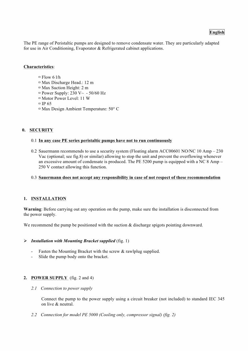
1. INSTALLATION Warning: Before carrying out any operation on the pump, make sure the installation is disconnected from the power supply. We recommend the pump be positioned with the suction & discharge spigots pointing downward. Installation with Mounting Bracket supplied (fig. 1)
- Fasten the Mounting Bracket with the screw & rawlplug supplied. - Slide the pump body onto the bracket.
2. POWER SUPPLY (fig. 2 and 4)
2.1 Connection to power supply
Connect the pump to the power supply using a circuit breaker (not included) to standard IEC 345 on live & neutral.
2.2 Connection for model PE 5000 (Cooling only, compressor signal) (fig. 2)
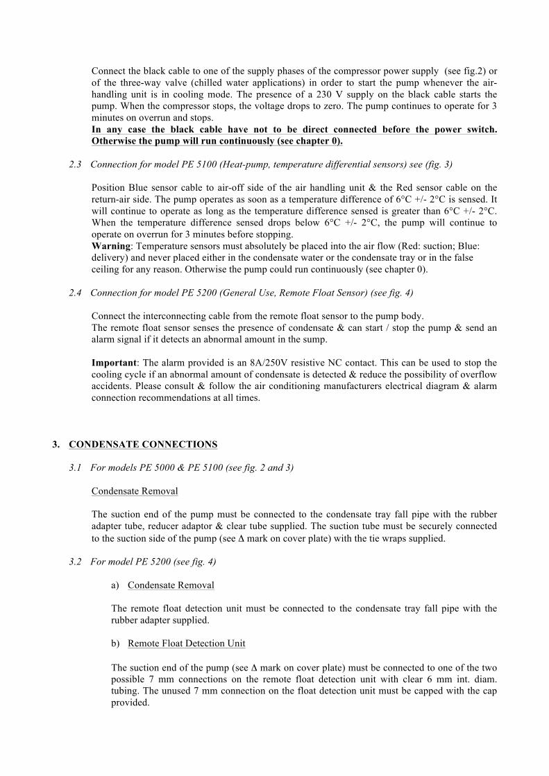
Connect the black cable to one of the supply phases of the compressor power supply (see fig.2) or of the three-way valve (chilled water applications) in order to start the pump whenever the air-handling unit is in cooling mode. The presence of a 230 V supply on the black cable starts the pump. When the compressor stops, the voltage drops to zero. The pump continues to operate for 3 minutes on overrun and stops. In any case the black cable have not to be direct connected before the power switch. Otherwise the pump will run continuously (see chapter 0).
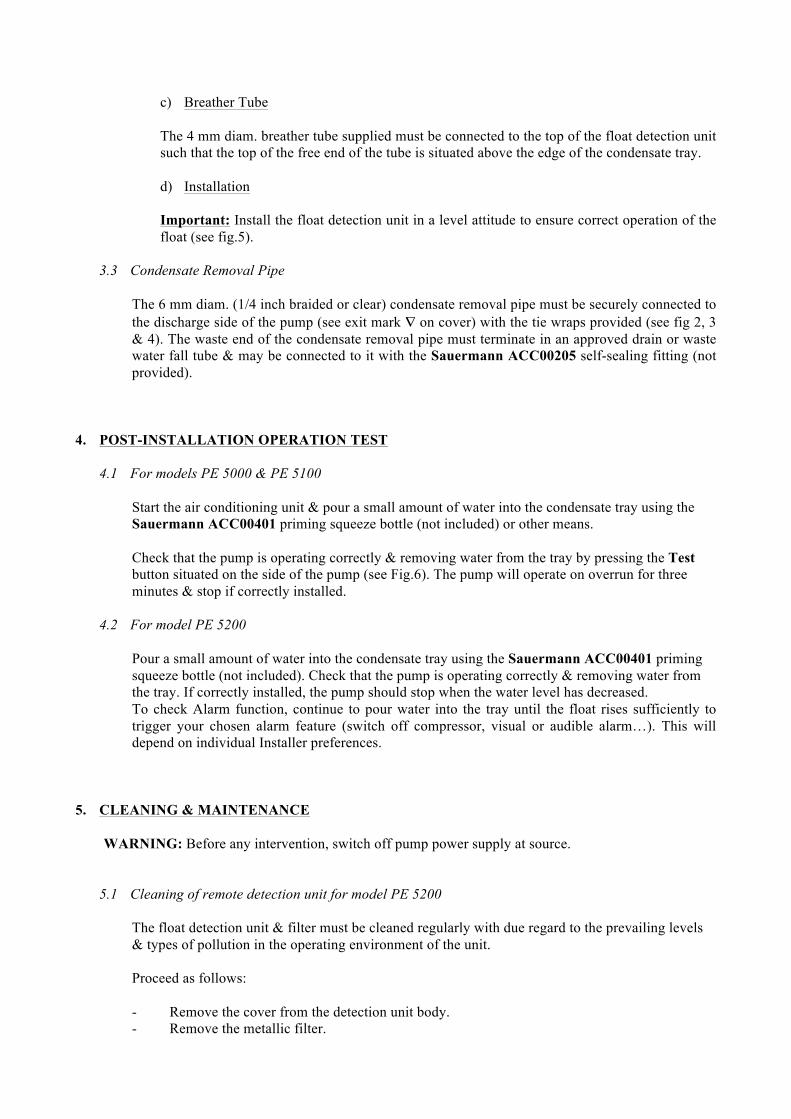
2.3 Connection for model PE 5100 (Heat-pump, temperature differential sensors) see (fig. 3)
Position Blue sensor cable to air-off side of the air handling unit & the Red sensor cable on the return-air side. The pump operates as soon as a temperature difference of 6°C +/- 2°C is sensed. It will continue to operate as long as the temperature difference sensed is greater than 6°C +/- 2°C. When the temperature difference sensed drops below 6°C +/- 2°C, the pump will continue to operate on overrun for 3 minutes before stopping. Warning: Temperature sensors must absolutely be placed into the air flow (Red: suction; Blue: delivery) and never placed either in the condensate water or the condensate tray or in the false ceiling for any reason. Otherwise the pump could run continuously (see chapter 0).
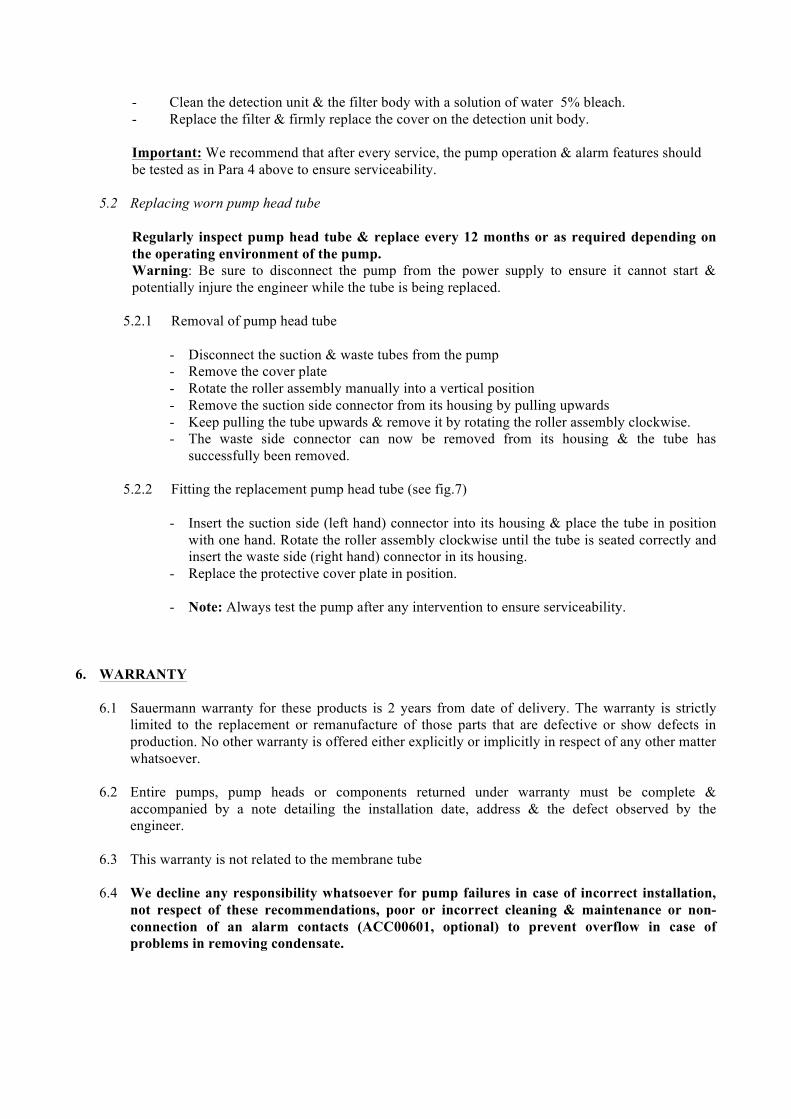
2.4 Connection for model PE 5200 (General Use, Remote Float Sensor) (see fig. 4)
Connect the interconnecting cable from the remote float sensor to the pump body. The remote float sensor senses the presence of condensate & can start / stop the pump & send an alarm signal if it detects an abnormal amount in the sump. Important: The alarm provided is an 8A/250V resistive NC contact. This can be used to stop the cooling cycle if an abnormal amount of condensate is detected & reduce the possibility of overflow accidents. Please consult & follow the air conditioning manufacturers electrical diagram & alarm connection recommendations at all times.
3. CONDENSATE CONNECTIONS
3.1 For models PE 5000 & PE 5100 (see fig. 2 and 3)
Condensate Removal The suction end of the pump must be connected to the condensate tray fall pipe with the rubber adapter tube, reducer adaptor & clear tube supplied. The suction tube must be securely connected to the suction side of the pump (see Δ mark on cover plate) with the tie wraps supplied.
3.2 For model PE 5200 (see fig. 4)
a) Condensate Removal The remote float detection unit must be connected to the condensate tray fall pipe with the rubber adapter supplied. b) Remote Float Detection Unit The suction end of the pump (see Δ mark on cover plate) must be connected to one of the two possible 7 mm connections on the remote float detection unit with clear 6 mm int. diam. tubing. The unused 7 mm connection on the float detection unit must be capped with the cap provided.
c) Breather Tube
The 4 mm diam. breather tube supplied must be connected to the top of the float detection unit such that the top of the free end of the tube is situated above the edge of the condensate tray. d) Installation
Important: Install the float detection unit in a level attitude to ensure correct operation of the float (see fig.5).
3.3 Condensate Removal Pipe
The 6 mm diam. (1/4 inch braided or clear) condensate removal pipe must be securely connected to the discharge side of the pump (see exit mark ∇ on cover) with the tie wraps provided (see fig 2, 3 & 4). The waste end of the condensate removal pipe must terminate in an approved drain or waste water fall tube & may be connected to it with the Sauermann ACC00205 self-sealing fitting (not provided).
4. POST-INSTALLATION OPERATION TEST
4.1 For models PE 5000 & PE 5100
Start the air conditioning unit & pour a small amount of water into the condensate tray using the Sauermann ACC00401 priming squeeze bottle (not included) or other means. Check that the pump is operating correctly & removing water from the tray by pressing the Test button situated on the side of the pump (see Fig.6). The pump will operate on overrun for three minutes & stop if correctly installed.
4.2 For model PE 5200
Pour a small amount of water into the condensate tray using the Sauermann ACC00401 priming squeeze bottle (not included). Check that the pump is operating correctly & removing water from the tray. If correctly installed, the pump should stop when the water level has decreased. To check Alarm function, continue to pour water into the tray until the float rises sufficiently to trigger your chosen alarm feature (switch off compressor, visual or audible alarm…). This will depend on individual Installer preferences.
5. CLEANING & MAINTENANCE
WARNING: Before any intervention, switch off pump power supply at source.
5.1 Cleaning of remote detection unit for model PE 5200
The float detection unit & filter must be cleaned regularly with due regard to the prevailing levels & types of pollution in the operating environment of the unit. Proceed as follows: - Remove the cover from the detection unit body. - Remove the metallic filter.
- Clean the detection unit & the filter body with a solution of water 5% bleach. - Replace the filter & firmly replace the cover on the detection unit body. Important: We recommend that after every service, the pump operation & alarm features should be tested as in Para 4 above to ensure serviceability.
5.2 Replacing worn pump head tube
Regularly inspect pump head tube & replace every 12 months or as required depending on the operating environment of the pump. Warning: Be sure to disconnect the pump from the power supply to ensure it cannot start & potentially injure the engineer while the tube is being replaced.
5.2.1 Removal of pump head tube
- Disconnect the suction & waste tubes from the pump - Remove the cover plate - Rotate the roller assembly manually into a vertical position - Remove the suction side connector from its housing by pulling upwards - Keep pulling the tube upwards & remove it by rotating the roller assembly clockwise. - The waste side connector can now be removed from its housing & the tube has
successfully been removed. 5.2.2 Fitting the replacement pump head tube (see fig.7)
- Insert the suction side (left hand) connector into its housing & place the tube in position
with one hand. Rotate the roller assembly clockwise until the tube is seated correctly and insert the waste side (right hand) connector in its housing.
- Replace the protective cover plate in position. - Note: Always test the pump after any intervention to ensure serviceability.
6. WARRANTY
6.1 Sauermann warranty for these products is 2 years from date of delivery. The warranty is strictly limited to the replacement or remanufacture of those parts that are defective or show defects in production. No other warranty is offered either explicitly or implicitly in respect of any other matter whatsoever.
6.2 Entire pumps, pump heads or components returned under warranty must be complete & accompanied by a note detailing the installation date, address & the defect observed by the engineer.
6.3 This warranty is not related to the membrane tube
6.4 We decline any responsibility whatsoever for pump failures in case of incorrect installation, not respect of these recommendations, poor or incorrect cleaning & maintenance or non-connection of an alarm contacts (ACC00601, optional) to prevent overflow in case of problems in removing condensate.
Français Les pompes péristaltiques série PE sont destinées à relever des condensats. Elles sont particulièrement adaptées aux climatiseurs, évaporateurs, vitrines réfrigérées…
Caractéristiques: Débit 6 l/h Refoulement max.: 12 m Aspiration max: 2 m Tension 230 V~ - 50/60 Hz Puissance du moteur: 11 W IP 65 Température ambiante max: 50° C 0. SECURITE
0.1 Les Pompes Péristaltiques de la série PE ne doivent en aucun cas fonctionner en continu.
0.2 Sauermann préconise l'utilisation d'un système de sécurité (Flotteur Alarme ACC00601 NO/NC 10 Amp – 230 Vac (en option; fig. 8) ou autre), afin de stopper la production de froid et prévenir ainsi le débordement du bac en cas d'afflux trop important de condensats. La pompe PE 5200 est équipée d'un contact NC 8 Amp – 250 V permettant cette fonction.
0.3 Sauermann décline toute responsabilité en cas de non respect de ces spécifications. 1. INSTALLATION Avertissement: avant toute intervention, mettre impérativement l’installation hors tension Fixer la pompe avec les raccords faisant face vers le bas. Installation avec le support fourni (fig. 1)
- Fixer le support à l’aide de la vis fournie - Accrocher la pompe sur son support en la faisant coulisser le long de la glissière sur l’arrière de la
pompe. 2. RACCORDEMENT ELECTRIQUE (fig. 2 et 4)
2.1 Raccordement au secteur
Raccorder les câbles d’alimentation au réseau par l’intermédiaire d’un dispositif de protection et de sectionnement électrique (non fourni) conforme à la norme IEC 345 sur la phase et le neutre.
2.2 Raccordement pour PE 5000 (signal compresseur) ( fig. 2)

Connecter le fil noir à l’une des phases de l’alimentation du compresseur (voir fig.2) ou de l’électrovanne (eau glacée), de manière à enclencher la pompe lorsque l’appareil est en mode froid. La présence d’un potentiel de 230 V sur ce fil noir fait démarrer la pompe. Lorsque le compresseur s’arrête, la tension devient nulle. La pompe continue à fonctionner pendant 3 minutes, puis elle s’arrête. Le fil noir ne doit en aucun cas être branché en direct sur le secteur. Ceci entraînerait un fonctionnement continu de la pompe. (Voir paragraphe 0.)
2.3 Raccordement pour PE 5100 (différence de température) ( fig 3) Fixer le fil avec le capteur bleu du côté (sonie d'air froid) du climatiseur et le capteur rouge du côté (air ambiant). La pompe est mise en marche à partir d'une différence de température de 6°C +/- 2°C. Tant que la différence de température est supérieure à 6°C +/- 2°C, la pompe fonctionnera. Lorsque la différence de température est inférieure à 6°C +/- 2°C, le courant est coupé et la pompe continue à fonctionner pendant 3 minutes avant de s'arrêter. Remarque: Les capteurs de température doivent être impérativement placés dans le flux d'air (Aspiration (rouge) et Soufflage (bleu)) et en aucun cas dans l'eau, dans le faux plafond ou sur les tubes frigorifiques, ce qui pourrait causer un dysfonctionnement ou le fonctionnement en continu de la pompe (voir paragraphe 0.)
2.4 Raccordement pour PE 5200 (bloc de détection) ( fig. 4)
Brancher le câble allant du bloc de détection à la pompe, le flotteur étant équipé d’un signal d’alarme. Important: pour le raccordement de l’alarme, vous disposez d’un contact inverseur NC, d’un pouvoir de coupure 8A/250V résistif. Ce contact peut être utilisé pour couper la production frigorifique en cas de risque de débordement, (après vérification du schéma électrique et de l’application client par l’installateur).
3. RACCORDEMENT HYDRAULIQUE
3.1 Pour PE 5000 et PE 5100 (fig. 2 et fig 3)
Collecte des condensats
L’embout d’aspiration de la pompe doit être raccordé à l’extrémité de la tuyauterie d’évacuation du bac de condensats, à l’aide du manchon caoutchouc, de la réduction et du tube diam. 6 mm fournis. Le tube d’aspiration doit être raccordé côté aspiration de la pompe (représenté sur le capot par Δ) et bloqué à l’aide des clips de serrage.
3.2 Pour PE 5200 (fig. 4)
a) Collecte des condensats Le bloc de détection doit être raccordé à l’extrémité de la tuyauterie d’évacuation du bac de condensats à l’aide du manchon caoutchouc fourni. b) Bloc de Détection L’embout d’aspiration (liaison sortie bloc de détection vers entrée pompe) de la pompe doit être relié à 1 des 2 embouts diam. 7 mm du bloc de détection avec 1 tube souple diam. 6 mm intérieur. L’autre embout diam. 7 mm doit impérativement être bouchonné (bouchon fourni).
c) Event
Le tube d’évent diam. 4 mm (fourni) doit être raccordé sur l’une de ses extrémités à la sortie supérieure du bloc de détection, l’autre extrémité doit rester à l’air libre (le diriger vers le haut). d) Position de montage
Monter le flotteur en respectant la position de montage du bloc de détection (fig.5).
3.3 Refoulement pompe
Le tube de refoulement de la pompe est raccordé sur la sortie de la pompe (représentée sur le capot ∇) puis bloqué à l’aide du clip de serrage (voir fig. 2,3,4). L’autre extrémité doit être reliée à la canalisation d’eau usée (ou autre) avec un tube souple diam. 6 mm intérieur. Il peut être raccordé à cette dernière grâce au raccord d’évacuation auto-étanche ACC00205 (non fourni).
4. TEST DE MISE EN SERVICE
4.1 Pour PE 5000, PE 5100
Mettre en marche votre climatiseur et versez un peu d’eau dans le bac de réception des condensats (utiliser la burette d’essai ACC00401). Vérifiez que la pompe évacue correctement l’eau contenue dans le bac. Vous pouvez utiliser le bouton test (3 minutes de marche) (voir fig.6) pour vider complètement l’eau du bac.
4.2 Pour PE 5200
Verser un peu d’eau dans le bac du climatiseur (utiliser la burette d’essai ACC00401). Vérifier que la pompe se met en marche et s’arrête lorsque le niveau d’eau est redescendu. Pour vérifier le fonctionnement de l’alarme, verser continuellement de l’eau jusqu’à ce que la fonction alarme se déclenche (coupure, alarme sonore ou visuelle…)
5. NETTOYAGE, ENTRETIEN
Avant toute intervention, mettre impérativement l’installation hors tension.
5.1 Nettoyage du bloc de détection (PE 5200)
Le bloc de détection et le filtre doivent être nettoyés. Ce nettoyage doit être effectué régulièrement selon le degré de pollution occasionné par l’environnement. Procéder comme suit: - Enlever le couvercle du bloc de détection - Retirer le filtre - Nettoyer le bloc de détection et le filtre avec une solution d’eau additionnée de 5 % d’eau de
javel. - Remettre le filtre et reclipser le couvercle. Faire un essai de fonctionnement de la pompe et
de l’alarme (§ 4/ MISE EN SERVICE).
5.2 Remplacement du tube de la pompe
Inspecter régulièrement le côté refoulement de la pompe et remplacer le tube de la pompe annuellement, ou plus fréquemment si nécessaire. Couper l’alimentation de la pompe, de manière à ce qu’elle ne démarre pas lors du changement de tube.
5.2.1 Pour enlever le tube
- Retirer le capot de protection - Positionner manuellement les galets à la verticale - Enlever le raccord hydraulique de gauche en tirant vers le haut. - Maintenir le tube tiré vers le haut d’une main, et le dégager en faisant tourner le porte
galet dans le sens des aiguilles d’une montre. 5.2.2 Pour la pose du tube
- Insérer le raccord hydraulique de gauche dans son logement et engager le tube dans le
fond, d’une main. De l’autre, tourner le porte galet dans le sens des aiguilles d’une montre jusqu’à engager le raccord hydraulique de droite.
- Faire glisser chaque raccord hydraulique dans son logement (voir fig.7) - Engager le capot dans la rainure supérieure de la pompe, ensuite le clipser en appuyant
sur les bords. 6. GARANTIE
6.1 2 ans à partir de la date de livraison. Cette garantie porte sur les pièces présentant des vices de
matière ou des défauts de fabrication et se limite au remplacement ou à la remise en état des pièces défectueuses, sans qu’aucun(e) indemnité ni dommage et intérêt ne puissent être réclamés. Cette Garantie exclut le tube de la pompe.
6.2 La pompe doit être retournée avec son bloc de détection, ne pas avoir été démontée et doit être accompagnée d’une note précisant le défaut constaté.
6.3 Cette Garantie exclut le tube de la pompe.
6.4 Nous déclinons toute responsabilité en cas d’installation non conforme, de non-respect des spécifications, de non-entretien ou de non-raccordement d’une alarme pour prévenir des débordements, en cas d’un défaut dans l’évacuation des condensats.
Italiano Le pompe peristaltiche della serie PE sono destinate allo scarico della condensa. Sono particolarmente adatte per condizionatori, evaporatori, vetrine refrigerate.…
Caratteristiche: Portata: 6 l/h Mandata max.: 12 m Aspirazione max: 2 m Tensione 230 V~ - 50/60 Hz Potenza del motore: 11 W IP 65 Temperatura ambiente max: 50° C 0. SICUREZZA
0.1 Le pompe peristaltiche della serie PE non devono in alcun caso lavorare in continuo.
0.2 Sauermann raccomanda l’uso di un sistema di sicurezza (Galleggiante d’allarme ACC00601 NO/NC
10 Amp – 230 Vac (optional; fig. 8) o altro sistema), al fine di fermare il condizionatore e prevenire la tracimazione del serbatoi in caso di eccessiva produzione di condensato. La pompa PE 5200 è equipaggiata con un contatto NC 8 Amp – 250 V che permette questa funzione.
0.3 Sauermann declina ogni responsabilità in caso di mancato rispetto di queste raccomandazioni
1. INSTALLAZIONE Nota importante: prima di qualsiasi intervento togliere tensione Fissare la pompa con i raccordi rivolti verso il basso. Non posizionare la pompa con il rotore o i raccordi rivolti verso l’alto. Installazione mediante il supporto in dotazione (fig. 1)
- Fissare il supporto mediante la vite in dotazione - Agganciare la pompa sul suo supporto facendola scorrere lungo la guida sulla parte posteriore della
pompa stessa. 2. COLLEGAMENTO ELETTRICO (fig. 2 e 4)
2.1 Collegamento
Collegare i cavi d’alimentazione alla rete mediante un dispositivo di protezione e di sezionamento elettrico (non fornito) conforme alla norma IEC 345 sulla fase e sul neutro.
2.2 Collegamento per PE 5000 (segnale compressore) ( fig. 2)
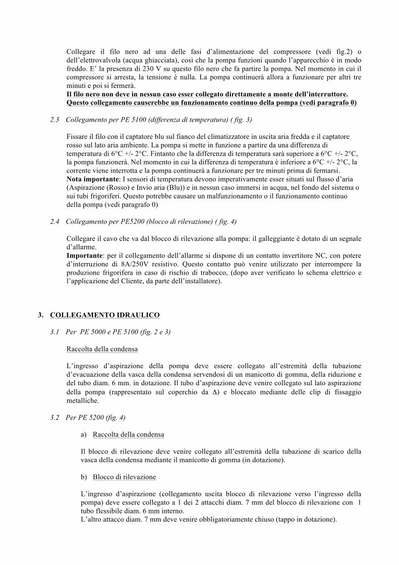
Collegare il filo nero ad una delle fasi d’alimentazione del compressore (vedi fig.2) o dell’elettrovalvola (acqua ghiacciata), così che la pompa funzioni quando l’apparecchio è in modo freddo. E’ la presenza di 230 V su questo filo nero che fa partire la pompa. Nel momento in cui il compressore si arresta, la tensione è nulla. La pompa continuerà allora a funzionare per altri tre minuti e poi si fermerà. Il filo nero non deve in nessun caso esser collegato direttamente a monte dell’interruttore. Questo collegamento causerebbe un funzionamento continuo della pompa (vedi paragrafo 0)
2.3 Collegamento per PE 5100 (differenza di temperatura) ( fig. 3)
Fissare il filo con il captatore blu sul fianco del climatizzatore in uscita aria fredda e il captatore rosso sul lato aria ambiente. La pompa si mette in funzione a partire da una differenza di temperatura di 6°C +/- 2°C. Fintanto che la differenza di temperatura sarà superiore a 6°C +/- 2°C, la pompa funzionerà. Nel momento in cui la differenza di temperatura è inferiore a 6°C +/- 2°C, la corrente viene interrotta e la pompa continuerà a funzionare per tre minuti prima di fermarsi. Nota importante: I sensori di temperatura devono imperativamente esser situati sul flusso d’aria (Aspirazione (Rosso) e Invio aria (Blu)) e in nessun caso immersi in acqua, nel fondo del sistema o sui tubi frigoriferi. Questo potrebbe causare un malfunzionamento o il funzionamento continuo della pompa (vedi paragrafo 0)
2.4 Collegamento per PE5200 (blocco di rilevazione) ( fig. 4)
Collegare il cavo che va dal blocco di rilevazione alla pompa: il galleggiante è dotato di un segnale d’allarme. Importante: per il collegamento dell’allarme si dispone di un contatto invertitore NC, con potere d’interruzione di 8A/250V resistivo. Questo contatto può venire utilizzato per interrompere la produzione frigorifera in caso di rischio di trabocco, (dopo aver verificato lo schema elettrico e l’applicazione del Cliente, da parte dell’installatore).
3. COLLEGAMENTO IDRAULICO
3.1 Per PE 5000 e PE 5100 (fig. 2 e 3)
Raccolta della condensa L’ingresso d’aspirazione della pompa deve essere collegato all’estremità della tubazione d’evacuazione della vasca della condensa servendosi di un manicotto di gomma, della riduzione e del tubo diam. 6 mm. in dotazione. Il tubo d’aspirazione deve venire collegato sul lato aspirazione della pompa (rappresentato sul coperchio da Δ) e bloccato mediante delle clip di fissaggio metalliche.
3.2 Per PE 5200 (fig. 4)
a) Raccolta della condensa Il blocco di rilevazione deve venire collegato all’estremità della tubazione di scarico della vasca della condensa mediante il manicotto di gomma (in dotazione).
b) Blocco di rilevazione L’ingresso d’aspirazione (collegamento uscita blocco di rilevazione verso l’ingresso della pompa) deve essere collegato a 1 dei 2 attacchi diam. 7 mm del blocco di rilevazione con 1 tubo flessibile diam. 6 mm interno. L’altro attacco diam. 7 mm deve venire obbligatoriamente chiuso (tappo in dotazione).
c) Sfiato
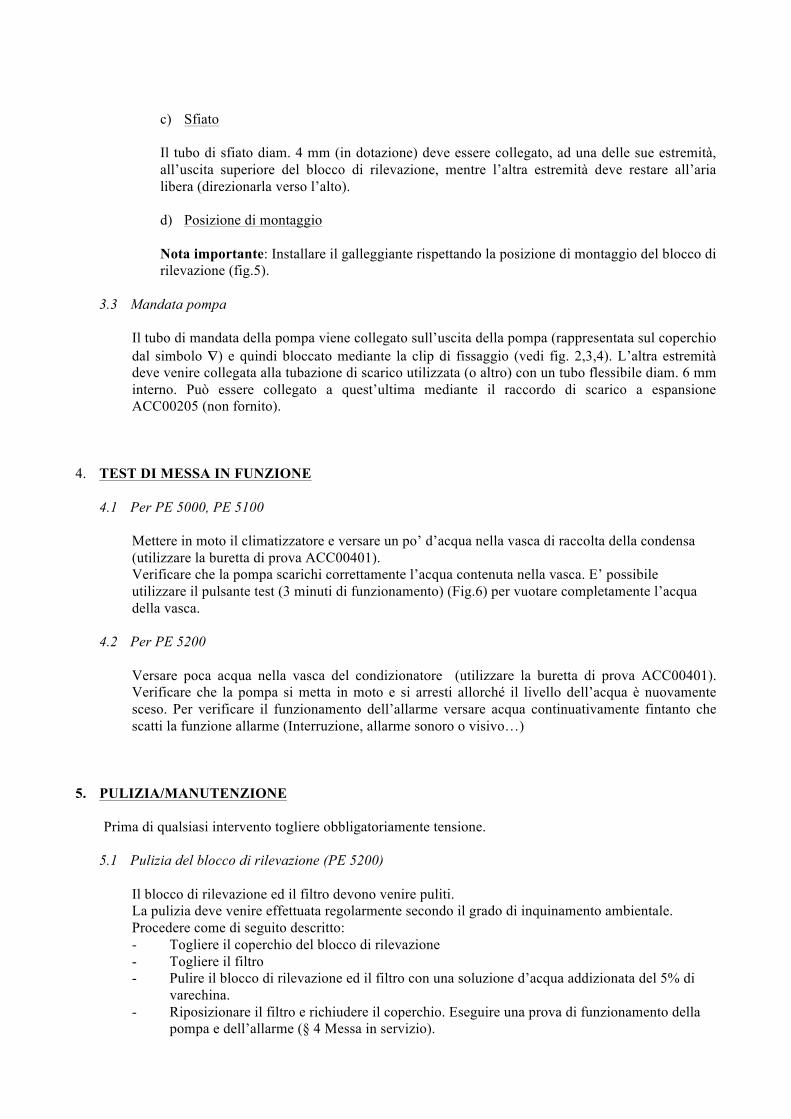
Il tubo di sfiato diam. 4 mm (in dotazione) deve essere collegato, ad una delle sue estremità, all’uscita superiore del blocco di rilevazione, mentre l’altra estremità deve restare all’aria libera (direzionarla verso l’alto). d) Posizione di montaggio Nota importante: Installare il galleggiante rispettando la posizione di montaggio del blocco di rilevazione (fig.5).
3.3 Mandata pompa
Il tubo di mandata della pompa viene collegato sull’uscita della pompa (rappresentata sul coperchio dal simbolo ∇) e quindi bloccato mediante la clip di fissaggio (vedi fig. 2,3,4). L’altra estremità deve venire collegata alla tubazione di scarico utilizzata (o altro) con un tubo flessibile diam. 6 mm interno. Può essere collegato a quest’ultima mediante il raccordo di scarico a espansione ACC00205 (non fornito).
4. TEST DI MESSA IN FUNZIONE
4.1 Per PE 5000, PE 5100
Mettere in moto il climatizzatore e versare un po’ d’acqua nella vasca di raccolta della condensa (utilizzare la buretta di prova ACC00401). Verificare che la pompa scarichi correttamente l’acqua contenuta nella vasca. E’ possibile utilizzare il pulsante test (3 minuti di funzionamento) (Fig.6) per vuotare completamente l’acqua della vasca.
4.2 Per PE 5200
Versare poca acqua nella vasca del condizionatore (utilizzare la buretta di prova ACC00401). Verificare che la pompa si metta in moto e si arresti allorché il livello dell’acqua è nuovamente sceso. Per verificare il funzionamento dell’allarme versare acqua continuativamente fintanto che scatti la funzione allarme (Interruzione, allarme sonoro o visivo…)
5. PULIZIA/MANUTENZIONE
Prima di qualsiasi intervento togliere obbligatoriamente tensione.
5.1 Pulizia del blocco di rilevazione (PE 5200)
Il blocco di rilevazione ed il filtro devono venire puliti. La pulizia deve venire effettuata regolarmente secondo il grado di inquinamento ambientale. Procedere come di seguito descritto: - Togliere il coperchio del blocco di rilevazione - Togliere il filtro - Pulire il blocco di rilevazione ed il filtro con una soluzione d’acqua addizionata del 5% di
varechina. - Riposizionare il filtro e richiudere il coperchio. Eseguire una prova di funzionamento della
pompa e dell’allarme (§ 4 Messa in servizio).
5.2 Sostituzione del tubo della pompa
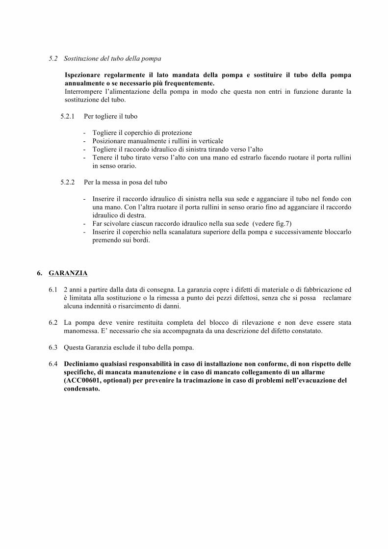
Ispezionare regolarmente il lato mandata della pompa e sostituire il tubo della pompa annualmente o se necessario più frequentemente. Interrompere l’alimentazione della pompa in modo che questa non entri in funzione durante la sostituzione del tubo.
5.2.1 Per togliere il tubo
- Togliere il coperchio di protezione - Posizionare manualmente i rullini in verticale - Togliere il raccordo idraulico di sinistra tirando verso l’alto - Tenere il tubo tirato verso l’alto con una mano ed estrarlo facendo ruotare il porta rullini
in senso orario. 5.2.2 Per la messa in posa del tubo
- Inserire il raccordo idraulico di sinistra nella sua sede e agganciare il tubo nel fondo con
una mano. Con l’altra ruotare il porta rullini in senso orario fino ad agganciare il raccordo idraulico di destra.
- Far scivolare ciascun raccordo idraulico nella sua sede (vedere fig.7) - Inserire il coperchio nella scanalatura superiore della pompa e successivamente bloccarlo
premendo sui bordi.
6. GARANZIA
6.1 2 anni a partire dalla data di consegna. La garanzia copre i difetti di materiale o di fabbricazione ed
è limitata alla sostituzione o la rimessa a punto dei pezzi difettosi, senza che si possa reclamare alcuna indennità o risarcimento di danni.
6.2 La pompa deve venire restituita completa del blocco di rilevazione e non deve essere stata manomessa. E’ necessario che sia accompagnata da una descrizione del difetto constatato.
6.3 Questa Garanzia esclude il tubo della pompa.
6.4 Decliniamo qualsiasi responsabilità in caso di installazione non conforme, di non rispetto delle specifiche, di mancata manutenzione e in caso di mancato collegamento di un allarme (ACC00601, optional) per prevenire la tracimazione in caso di problemi nell’evacuazione del condensato.
Español
Las bombas peristálticas de la serie PE están destinadas para absorber los condensados. Se adaptan particularmente para climatizadores, evaporadores, vitrinas refrigeradas, etc.
Características:
- Caudal 6 l/h - Impulsión máx. 12 m. - Aspiración máx. 2 m. - Tensión de alimentación: 230 V – 50/60 Hz - Potencia del motor: 11 W - Grado de protección: IP 65 - Temperatura ambiente máx. 50ºC
0. SEGURIDAD
0.1 Las bombas peristálticas de la serie PE no deben, en ningún caso, trabajar sin pausas. 0.2 Sauermann recomienda el uso de un sistema de seguridad (Flotador de alarma ACC00601 NO/NC
10 Amp – 230 Vac (opcional; fig. 8) u otro sistema) al fin de detener el climatizador y prevenir el desbordamiento del depósito en caso de producción excesiva de líquido condensado. La bomba PE 5200 está dotada de un contacto NC 8 Amp – 250 V que permite esta función.
0.3 Sauermann declina toda responsabilidad en caso de inobservancia de estas recomendaciones.
1. INSTALACIÓN Atención: ante cualquier intervención, compruebe que la instalación esté fuera de tensión.
Fijar la bomba con los rácores en la posición inferior.
Instalación con la escuadra de fijación (incluida en la bomba) (fig.1).
- Fijar la escuadra de fijación con el tornillo suministrado. - Fijar la bomba a la escuadra haciéndola deslizar en la corredera.
2. CONEXIÓN ELÉCTRICA (fig. 2 y 4)
2.1 Conexión a la red
Conectar los cables de la alimentación a la red mediante un dispositivo de protección y de seccionamiento eléctrico (no suministrado con la bomba) conforme a la norma IEC 345 sobre la fase y el neutro.
2.2 Conexión para la PE 5000 (señal del compresor) (fig. 2)
Conectar el hilo negro a una de las fases de la alimentación del compresor (ver fig. 2) o de la electroválvula (agua helada), de tal forma que la bomba se ponga en marcha cuando el aparato esté
en modo frío. La presencia de un potencial de 230 V en este hilo, hace arrancar la bomba. Cuando el compresor se para, la tensión se vuelve nula. La bomba seguirá funcionando durante 3 minutos y luego se parará. El cable negro, en ningún caso se debe conectar directamente con el interruptor. Esta conexión provocaría un funcionamiento continuo de la bomba (ver punto 0).
2.3 Conexión para la PE 5100 (diferencia de temperatura) (fig. 3)
Fijar el hilo con el captor azul del lado (salida del aire frío) del climatizador y el captor rojo del lado (aire ambiente). La bomba se pone en marcha a partir de una diferencia de temperatura de 6°C +/- 2°C. Mientras la diferencia de temperatura sea superior a estos 6°C +/- 2°C, la bomba funcionará. Cuando la diferencia de temperatura sea inferior a 6°C +/- 2°C, se cortará la corriente y la bomba seguirá funcionando durante 3 minutos y luego se parará. Atención: los sensores de temperatura obligatoriamente deben colocarse en el flujo de aire (Aspiración (Rojo) y envío de aire (Azul) y en ningún caso se deben sumergir en agua, en el fondo del sistema o en los tubos frigoríficos. Esto podría provocar un malfuncionamiento o el funcionamiento continuo de la bomba (ver punto 0).
2.4 Conexión para la PE 5200 (bloque de detección) (fig. 4)
Conectar el cable que va del bloque de detección hasta la bomba, el flotador está equipado de una señal de alarma. Importante: para la conexión de la alarma, usted dispone de un contacto inversor NC con un poder de corte 8A / 250 V resistivo. Este contacto se puede usar para cortar la producción frigorífica en caso de riesgo de desbordamiento. (Después de haber verificado el esquema eléctrico y la aplicación cliente por el instalador).
3. CONEXIÓN HIDRÁULICA
3.1 Para PE 5000 y PE 5100 (fig. 2 y 3)
Recolección de condensados El racor de aspiración de la bomba debe conectarse a la extremidad del tubo de evacuación de la bandeja de condensados, mediante un enlace de caucho, de la reducción y del tubo diám. 6 mm. que se entrega con la bomba. El tubo de aspiración debe conectarse del lado de la aspiración de la bomba (representado sobre la tapa A) y bloqueado con abrazaderas metálicas.
3.2 Para PE 5200 (fig. 4)
a) Recolección de condensados.
El bloque de detección debe conectarse a la extremidad del lado de evacuación de la bandeja de condensados mediante el enlace de caucho ACC 00205 que se entrega con la bomba.
b) Bloque de detección.
La contera de aspiración (conexión salida bloque de detección hacia entrada de la bomba) de la bomba debe estar conectada a una de las dos conteras diám. 7 mm. del bloque de detección con un tubo flexible diám. int. 6 mm. La otra contera diám. 7 mm. debe cerrarse imperativamente con un tapón (que se entrega con la bomba).
c) Respiradero
El tubo respiradero diám. 4 mm. ( que se entrega con la bomba) debe conectarse sobre una de las extremidades a la salida superior del bloque de detección, la otra extremidad debe quedarse al aire libre (dirigida hacia arriba)
d) Posición de montaje Montar el flotador respetando la posición de montaje del bloque de detección (fig. 5)
3.3 Impulsión de la bomba
El tubo de impulsión de la bomba se conecta a la salida de la bomba (representada sobre la tapa A) y luego se bloquea con una abrazadera metálica (ver fig. 2, 3, 4). La otra extremidad debe conectarse a la canalización de agua usada con un tubo flexible diám. 6 mm. interior. Se puede hacer esta conexión gracias al rácor de evacuación auto estanco ACC 00205 que se debe comprar separadamente.
4. PRUEBA DE PUESTA EN SERVICIO
4.1 Para PE 5000 y PE 5100
Poner en marcha el climatizador y verter un poco de agua en la bandeja de condensados (utilizar la boya de arranque ACC 00401). Verificar que al bomba evacue correctamente el agua contenida en la bandeja. Usted puede utilizar el pulsador de prueba (3 minutos de marcha) para vaciar completamente la bandeja.
4.2 Para PE 5200
Poner en marcha el climatizador y verter un poco de agua en la bandeja del climatizador (utilizar la boya de arranque ACC 00401). Verificar que la bomba se pone en marcha y se para cuando el nivel del agua haya bajado. Para verificar el funcionamiento de la alarma, verter continuamente agua hasta que la alarma se ponga en marcha (corte, alarma sonora o visual ...)
5. LIMPIEZA Y MANTENIMIENTO
Ante cualquier intervención, compruebe que la instalación esté fuera de tensión.
5.1 Limpieza del bloque de detección (PE 5200)
El bloque de detección y el filtro deben ser limpiados. Esta limpieza debe efectuarse regularmente según el grado de polución ocasionado por el ambiente. Proceder como sigue: - Quitar la tapa del bloque de detección - Retirar el filtro - Limpiar el bloque de detección y el filtro con una solución de agua con 5% de lejía. - Poner el filtro y su tapa.
Hacer una prueba de funcionamiento de la bomba y de la alarma (ver parágrafo 4. PRUEBA DE PUESTA EN SERVICIO)
5.2 Cambio del tubo de la bomba.
Verificar regularmente el lado de impulsión de la bomba y reemplazar el tubo de la bomba anualmente o más frecuentemente si fuese necesario. Cortar la alimentación de la bomba de tal forma que no arranque durante el cambio de tubo.
5.2.1. Para quitar el tubo
- Retirar la tapa de protección - Posicionar manualmente los rodillos a la vertical - Quitar el rácor hidráulico de la izquierda tirando hacia arriba - Sujetar el tubo tirando hacia arriba con una mano y soltarlo haciendo girar el portarodillos en el
sentido de las agujas del reloj.
5.2.2. Para poner el tubo
- Insertar el rácor hidráulico de la izquierda en su sitio e introducir el tubo en el fondo con una mano. Con la otra, girar el portarodillos en el sentido de las agujas del reloj hasta introducir el rácor hidráulico de la derecha.
- Hacer deslizar cada rácor hidráulico en su sitio (ver fig. 7) - Tomar la tapa de protección orientando la ranura frente a usted, introducirla en la ranura
superior de la bomba. Luego pones las abrazaderas y hacer presión en los bordes. 6. GARANTÍA
6.1 2 años a partir de la fecha de entrega. Esta garantía se da para las piezas que presentan un vicio del material o defectos de fabricación y se limita al reemplazo o al arreglo de las piezas defectuosas, sin posibilidad ninguna para conseguir indemnización ni daños y perjuicios.
6.2 La bomba debe devolverse con su bloque de detección y que no se haya desmontado. Debe
adjuntarse una nota precisando el defecto constatado. 6.3 Esta Garantía no es aplicable al tubo de la bomba. 6.4 Declinamos toda responsabilidad en caso de que la instalación no sea conforme, que no
respete las especificaciones, las reglas de mantenimiento, la instalación y conexión de alarmas para prevenir desbordamientos, en el caso de un defecto en la evacuación de los condensados.
Deutsch
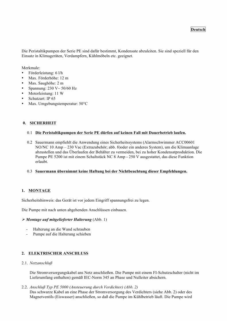
Die Peristaltikpumpen der Serie PE sind dafür bestimmt, Kondensate abzuleiten. Sie sind speziell für den Einsatz in Klimageräten, Verdampfern, Kühlmöbeln etc. geeignet.
Merkmale: • Förderleistung: 6 l/h • Max. Förderhöhe: 12 m • Max. Saughöhe: 2 m • Spannung: 230 V~ 50/60 Hz • Motorleistung: 11 W • Schutzart: IP 65 • Max. Umgebungstemperatur: 50°C 0. SICHERHEIT
0.1 Die Peristaltikpumpen der Serie PE dürfen auf keinen Fall mit Dauerbetrieb laufen.
0.2 Sauermann empfiehlt die Anwendung eines Sicherheitssystems (Alarmschwimmer ACC00601
NO/NC 10 Amp – 230 Vac (Extrazubehör; abb. 8)oder ein anderes System), um die Klimaanlage abzustellen und das Überlaufen der Behälter zu vermeiden, bei zu hoher Kondensatproduktion. Die Pumpe PE 5200 ist mit einem Schaltstück NC 8 Amp - 250 V ausgestattet, das diese Funktion erlaubt.
0.3 Sauermann übernimmt keine Haftung bei der Nichtbeachtung dieser Empfehlungen.
1. MONTAGE Sicherheitshinweis: das Gerät ist vor jedem Eingriff spannungsfrei zu legen. Die Pumpe mit nach unten abgehenden Anschlüssen einbauen. Montage auf mitgelieferter Halterung (Abb. 1)
- Halterung an die Wand schrauben - Pumpe auf die Halterung schieben
2. ELEKTRISCHER ANSCHLUSS 2.1. Netzanschluß
Die Stromversorgungskabel ans Netz anschließen. Die Pumpe mit einem FI-Schutzschalter (nicht im Lieferumfang enthalten) gemäß IEC-Norm 345 an Phase und Nulleiter absichern.
2.2. Anschluß Typ PE 5000 (Ansteuerung durch Verdichter) (Abb. 2) Das schwarze Kabel an eine Phase der Stromversorgung des Verdichters (siehe Abb. 2) oder des Magnetventils (Eiswasser) anschließen, so daß die Pumpe im Kühlbetrieb läuft. Die Pumpe wird
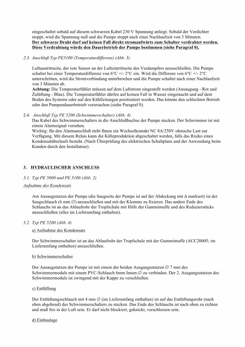
eingeschaltet sobald auf diesem schwarzen Kabel 230 V Spannung anliegt. Sobald der Verdichter stoppt, wird die Spannung null und die Pumpe stoppt nach einer Nachlaufzeit von 3 Minuten. Der schwarze Draht darf auf keinen Fall direkt stromaufwärts zum Schalter verdrahtet werden. Diese Verdrahtung würde den Dauerbetrieb der Pumpe bestimmen (siehe Paragraf 0).
2.3. Anschluß Typ PE5100 (Temperaturdifferenz) (Abb. 3) Luftaustrittseite, der rote Sensor an der Lufteintrittseite des Verdampfers anzuschließen. Die Pumpe schaltet bei einer Temperaturdifferenz von 6°C +/- 2°C ein. Wird die Differenz von 6°C +/- 2°C unterschritten, wird die Stromverbindung unterbrochen und die Pumpe schaltet nach einer Nachlaufzeit von 3 Minuten ab. Achtung: Die Temperaturfühler müssen auf dem Luftstrom eingestellt werden (Ansaugung - Rot und Zulüftung - Blau). Die Temperaturfühler dürfen auf keinen Fall in Wasser eingetaucht und auf dem Boden des Systems oder auf den Kühlleitungen positioniert werden. Das könnte den schlechten Betrieb oder den Pumpendauerbetrieb verursachen (siehe Paragraf 0).
2.4. Anschluß Typ PE 5200 (Schwimmerschalter) (Abb. 4) Das Kabel des Schwimmerschalters in die Anschlußbuchse der Pumpe stecken. Der Schwimmer ist mit einem Alarmsignal versehen. Wichtig: für den Alarmanschluß steht Ihnen ein Wechselkontakt NC 8A/250V ohmsche Last zur Verfügung. Mit diesem Relais kann die Kälteproduktion abgeschaltet werden, falls das Risiko eines Kondensatüberlaufs besteht. (Nach Überprüfung des elektrischen Schaltplans und der Anwendung beim Kunden durch den Installateur).
3. HYDRAULISCHER ANSCHLUSS
3.1. Typ PE 5000 und PE 5100 (Abb. 2)
Aufnahme des Kondensats Am Ansaugstutzen der Pumpe (die Saugseite der Pumpe ist auf der Abdeckung mit Δ markiert) ist der Saugschlauch (6 mm ∅) anzuschließen und mit der Klemme zu fixieren. Das andere Ende des Schlauchs ist an das Ablaufrohr der Tropfschale mit Hilfe der Gummimuffe und des Reduzierstücks anzuschließen (alles im Lieferumfang enthalten).
3.2. Typ PE 5200 (Abb. 4)
a) Aufnahme des Kondensats Der Schwimmerschalter ist an das Ablaufrohr der Tropfschale mit der Gummimuffe (ACC20005; im Lieferumfang enthalten) anzuschließen. b) Schwimmerschalter Der Ansaugstutzen der Pumpe ist mit einem der beiden Ausgangsstutzen ∅ 7 mm des Schwimmermoduls mit einem PVC-Schlauch 6mm Innen-∅ zu verbinden. Der 2. Ausgangsstutzen des Schwimmermoduls ist zwingend mit der Kappe zu verschließen. c) Entlüftung Der Entlüftungsschlauch mit 4 mm ∅ (im Lieferumfang enthalten) ist auf das Entlüftungsrohr (nach oben abgehend) des Schwimmerschalters zu stecken. Das Ende des Schlauchs ist nach oben zu richten und muß frei in der Luft sein. Er darf nicht blockiert, geknickt, verschlossen sein. d) Einbaulage
Die vorgeschriebene Einbaulage des Schwimmerschalters ist zu beachten (Abb. 5)
3.3 . Druckseite der Pumpe
Der ableitende Kondensatschlauch ist an der Ausgangseite der Pumpe (auf der Abdeckung mit einem ∇ markiert) anzuschließen und mit der Klemme zu fixieren (siehe Abb. 2, 3, 4). Das andere Ende ist an die Abwasserleitung anzuschließen. Dieser Anschluß kann einfach mit dem selbstdichtenden Ablaufstutzen (ACC00205; nicht im Lieferumfang enthalten) durchgeführt werden.
4. FUNKTIONSTEST 4.1. Typ PE 5000, PE 5100
Klimagerät einschalten und etwas Wasser in die Tropfschale gießen. (Verwenden Sie dazu die Einfüllflasche ACC00401; nicht im Lieferumfang enthalten). Überprüfen Sie, ob die Pumpe das Wasser korrekt absaugt. Sie können den Testknopf drücken (3 Minuten Laufzeit) (Abb.6), um die Tropfschale vollständig zu entleeren.
4.2. Type PE 5200
Gießen Sie etwas Wasser in die Tropfschale des Klimageräts. (Verwenden Sie hierzu die Einfüllflasche ACC00401; nicht im Lieferumfang enthalten). Überprüfen Sie, ob die Pumpe anläuft und wieder abschaltet, nachdem der Wasserspiegel wieder abgesunken ist. Um die Alarmfunktion zu überprüfen, gießen Sie ständig Wasser zu, bis Alarm ausgelöst wird (Abschalten des Klimageräts, akustischer oder visueller Alarm)
5. REINIGUNG, WARTUNG Vor jedem Eingriff das Gerät spannungsfrei legen. 5.1. Reinigung des Schwimmermoduls (PE 5200) Das Schwimmermodul und der Filter müssen in regelmäßigen Abständen gereinigt werden:
- Deckel des Schwimmermoduls abheben - Filter herausnehmen - Schwimmermodul und Filter mit einer Lösung aus 5% chlorhaltigem Wasser reinigen - Filter wieder einsetzen und Deckel aufclipsen. Funktionstest (§ 4) durchführen.
5.2. Wechsel des Pumpenschlauchs Die Druckseite der Pumpe regelmäßig überprüfen und den Pumpenschlauch alle 12 Monate – bei Bedarf öfters – wechseln.
Die Stromversorgung der Pumpe unterbrechen, damit sie während der Wartungsarbeiten nicht startet.
5.2.1. Schlauch entfernen - Abdeckung entfernen - die Walzen manuell vertikal ausrichten - den Hydraulikanschluß auf der linken Seite herausziehen
- den nach oben gezogenen Pumpenschlauch mit der einen Hand halten und mit der anderen Hand den Rotor im Uhrzeigersinn drehen und den Schlauch herausdrehen.
5.2.2. Einsetzen des neuen Schlauches
- Den Schlauch auf die beiden Hydraulikanschlüsse schieben und mit Kabelbindern (im Lieferumfang enthalten) fixieren. Einen hydraulischen Anschluß auf der linken Seite einsetzen. Den Rotor im Uhrzeigersinn drehen und dabei den Schlauch über die Walzen und unter die Rotorblätter legen. - Den rechten hydraulischen Anschluß ebenfalls auf seine Öffnung setzen und beide Anschlüsse nach hinten schieben. (Abb. 7) - Abdeckung auf die Pumpe schieben und durch Drücken auf die Ränder einrasten lassen.
6. GARANTIE
6.1 Die Garantiezeit beträgt 2 Jahre ab Lieferdatum. Die Garantie erstreckt sich auf Material- und
Fabrikationsfehler und beschränkt sich auf Austausch oder Instandsetzung der schadhaften Teile, ohne Anspruch auf Schadenersatz oder Folgekosten.
6.2 Die Pumpe muß komplett (inkl. Schwimmermodul) eingeschickt werden, ohne daß sie vorher
demontiert wurde. Eine kurze Fehlerbeschreibung ist beizulegen. 6.3 Für den Membranschlauch wird keine Garantie gewährt. 6.4 Wir lehnen jede Haftung für mangelhafte Kondensatableitung ab bei falscher Installation,
Nichteinhaltung der Vorschriften, falscher oder nicht durchgeführter Wartung oder Nichtanschluß des Alarmkontakts, um Kondensatüberlauf zu verhindern.
Nederlands
De peristaltische pompen van de serie PE zijn speciaal geschikt voor het afvoeren van condenswater
van klimaatregelapparaten, verdampers, koelvitrines ontvochtigers enz.…
Kenmerken: • Pompcapaciteit: 6 liter/uur • Opvoerhoogte max.: 12 m • Aanzuighoogte max.: 2 m • Voeding 230 V~ - 50/60 Hz • Vermogen van de motor: 11 W • Behuizing IP 65 • Omgevingstemperatuur max: 50° C 0. VEILIGHEID
0.1 De peristaltische pompen van de serie PR mogen in geen geval continu draaien.
0.2 Sauermann raadt een beveiligingssysteem aan (Veiligheidsvlotter ACC00601 NO/NC 10 Amp - 230
Vac (optional; afb. 8) of een ander systeem) dat de condensor stopt en overlopen van de tank voorkomt als er te veel condens wordt geproduceerd. De pomp PE 5200 is uitgerust met een NC 8 Amp - 250 V contact voor deze functie.
0.3 Sauermann is in geen geval aansprakelijk voor overtredingen van deze voorschriften 1. INSTALLATIE Belangrijk: schakel altijd eerst de voeding uit voordat werkzaamheden verricht worden, Bevestig de pomp met de slangtuiten naar onder gericht. Installatie met behulp van het bijgeleverde montageplaatje (afb. 1)
- Bevestig het plaatje aan de wand of unit met behulp van de bijgeleverde schroef - Monteer de pomp aan het plaatje door deze langs de geleiders aan de achterzijde van boven naar
beneden te schuiven. 2. ELEKTRISCHE AANSLUITING (afb. 2.4)
2.1 Aansluiting
Verbind de voedingskabels met het net via een veiligheidsschakelaar en een lijnonderbreker (niet bijgeleverd) conform de norm IEC 345 op de fase en op de neutraal. Advies: geef de pomp een aparte voeding. Op deze manier functioneert pomp altijd onafhankelijk van de (koel)unit.
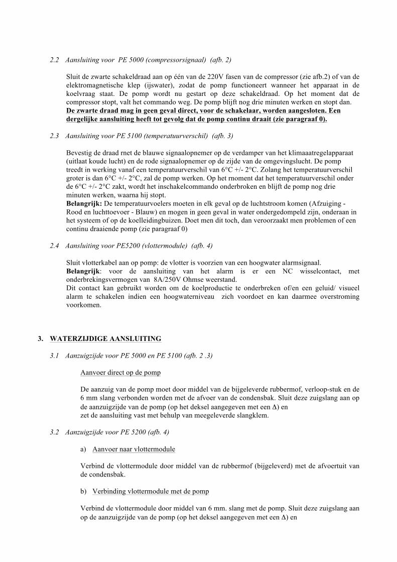
2.2 Aansluiting voor PE 5000 (compressorsignaal) (afb. 2)
Sluit de zwarte schakeldraad aan op één van de 220V fasen van de compressor (zie afb.2) of van de elektromagnetische klep (ijswater), zodat de pomp functioneert wanneer het apparaat in de koelvraag staat. De pomp wordt nu gestart op deze schakeldraad. Op het moment dat de compressor stopt, valt het commando weg. De pomp blijft nog drie minuten werken en stopt dan. De zwarte draad mag in geen geval direct, voor de schakelaar, worden aangesloten. Een dergelijke aansluiting heeft tot gevolg dat de pomp continu draait (zie paragraaf 0).
2.3 Aansluiting voor PE 5100 (temperatuurverschil) (afb. 3) Bevestig de draad rnet de blauwe signaalopnemer op de verdamper van het klimaaatregelapparaat (uitlaat koude lucht) en de rode signaalopnemer op de zijde van de omgevingslucht. De pomp treedt in werking vanaf een temperatuurverschil van 6°C +/- 2°C. Zolang het temperatuurverschil groter is dan 6°C +/- 2°C, zal de pomp werken. Op het rnoment dat het temperatuurverschil onder de 6°C +/- 2°C zakt, wordt het inschakelcommando onderbroken en blijft de pomp nog drie minuten werken, waarna hij stopt. Belangrijk: De temperatuurvoelers moeten in elk geval op de luchtstroom komen (Afzuiging - Rood en luchttoevoer - Blauw) en mogen in geen geval in water ondergedompeld zijn, onderaan in het systeem of op de koelleidingbuizen. Doet men dit toch, dan veroorzaakt men problemen of een continu draaiende pomp (zie paragraaf 0)
2.4 Aansluiting voor PE5200 (vlottermodule) (afb. 4)
Sluit vlotterkabel aan op pomp: de vlotter is voorzien van een hoogwater alarmsignaal. Belangrijk: voor de aansluiting van het alarm is er een NC wisselcontact, met onderbrekingsvermogen van 8A/250V Ohmse weerstand. Dit contact kan gebruikt worden om de koelproductie te onderbreken of/en een geluid/ visueel alarm te schakelen indien een hoogwaterniveau zich voordoet en kan daarmee overstroming voorkomen.
3. WATERZIJDIGE AANSLUITING
3.1 Aanzuigzijde voor PE 5000 en PE 5100 (afb. 2 .3)
Aanvoer direct op de pomp
De aanzuig van de pomp moet door middel van de bijgeleverde rubbermof, verloop-stuk en de 6 mm slang verbonden worden met de afvoer van de condensbak. Sluit deze zuigslang aan op de aanzuigzijde van de pomp (op het deksel aangegeven met een Δ) en zet de aansluiting vast met behulp van meegeleverde slangklem.
3.2 Aanzuigzijde voor PE 5200 (afb. 4)
a) Aanvoer naar vlottermodule Verbind de vlottermodule door middel van de rubbermof (bijgeleverd) met de afvoertuit van de condensbak. b) Verbinding vlottermodule met de pomp Verbind de vlottermodule door middel van 6 mm. slang met de pomp. Sluit deze zuigslang aan op de aanzuigzijde van de pomp (op het deksel aangegeven met een Δ) en
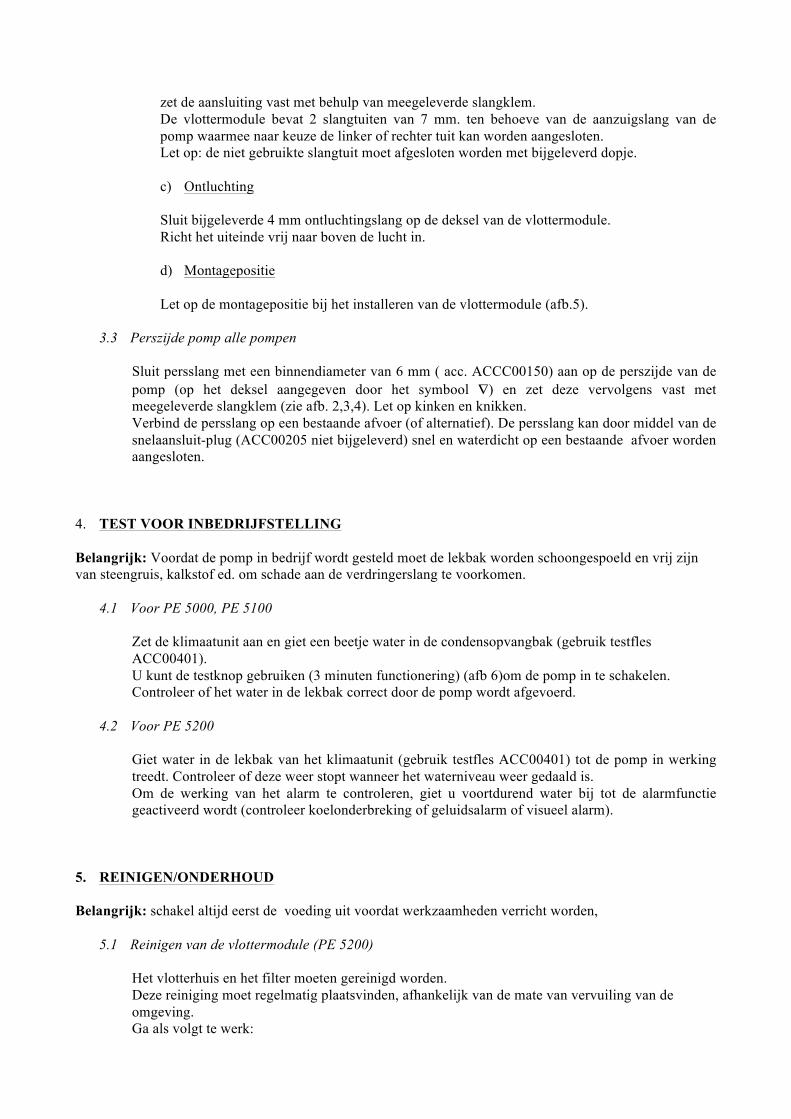
zet de aansluiting vast met behulp van meegeleverde slangklem. De vlottermodule bevat 2 slangtuiten van 7 mm. ten behoeve van de aanzuigslang van de pomp waarmee naar keuze de linker of rechter tuit kan worden aangesloten. Let op: de niet gebruikte slangtuit moet afgesloten worden met bijgeleverd dopje. c) Ontluchting Sluit bijgeleverde 4 mm ontluchtingslang op de deksel van de vlottermodule. Richt het uiteinde vrij naar boven de lucht in. d) Montagepositie Let op de montagepositie bij het installeren van de vlottermodule (afb.5).
3.3 Perszijde pomp alle pompen
Sluit persslang met een binnendiameter van 6 mm ( acc. ACCC00150) aan op de perszijde van de pomp (op het deksel aangegeven door het symbool ∇) en zet deze vervolgens vast met meegeleverde slangklem (zie afb. 2,3,4). Let op kinken en knikken. Verbind de persslang op een bestaande afvoer (of alternatief). De persslang kan door middel van de snelaansluit-plug (ACC00205 niet bijgeleverd) snel en waterdicht op een bestaande afvoer worden aangesloten.
4. TEST VOOR INBEDRIJFSTELLING Belangrijk: Voordat de pomp in bedrijf wordt gesteld moet de lekbak worden schoongespoeld en vrij zijn van steengruis, kalkstof ed. om schade aan de verdringerslang te voorkomen.
4.1 Voor PE 5000, PE 5100
Zet de klimaatunit aan en giet een beetje water in de condensopvangbak (gebruik testfles ACC00401). U kunt de testknop gebruiken (3 minuten functionering) (afb 6)om de pomp in te schakelen. Controleer of het water in de lekbak correct door de pomp wordt afgevoerd.
4.2 Voor PE 5200
Giet water in de lekbak van het klimaatunit (gebruik testfles ACC00401) tot de pomp in werking treedt. Controleer of deze weer stopt wanneer het waterniveau weer gedaald is. Om de werking van het alarm te controleren, giet u voortdurend water bij tot de alarmfunctie geactiveerd wordt (controleer koelonderbreking of geluidsalarm of visueel alarm).
5. REINIGEN/ONDERHOUD
Belangrijk: schakel altijd eerst de voeding uit voordat werkzaamheden verricht worden,
5.1 Reinigen van de vlottermodule (PE 5200)
Het vlotterhuis en het filter moeten gereinigd worden. Deze reiniging moet regelmatig plaatsvinden, afhankelijk van de mate van vervuiling van de omgeving. Ga als volgt te werk:
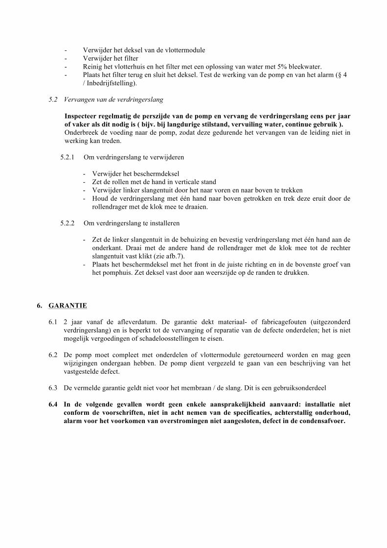
- Verwijder het deksel van de vlottermodule - Verwijder het filter - Reinig het vlotterhuis en het filter met een oplossing van water met 5% bleekwater. - Plaats het filter terug en sluit het deksel. Test de werking van de pomp en van het alarm (§ 4
/ Inbedrijfstelling).
5.2 Vervangen van de verdringerslang
Inspecteer regelmatig de perszijde van de pomp en vervang de verdringerslang eens per jaar of vaker als dit nodig is ( bijv. bij langdurige stilstand, vervuiling water, continue gebruik ). Onderbreek de voeding naar de pomp, zodat deze gedurende het vervangen van de leiding niet in werking kan treden.
5.2.1 Om verdringerslang te verwijderen
- Verwijder het beschermdeksel - Zet de rollen met de hand in verticale stand - Verwijder linker slangentuit door het naar voren en naar boven te trekken - Houd de verdringerslang met één hand naar boven getrokken en trek deze eruit door de
rollendrager met de klok mee te draaien. 5.2.2 Om verdringerslang te installeren
- Zet de linker slangentuit in de behuizing en bevestig verdringerslang met één hand aan de
onderkant. Draai met de andere hand de rollendrager met de klok mee tot de rechter slangentuit vast klikt (zie afb.7).
- Plaats het beschermdeksel met het front in de juiste richting en in de bovenste groef van het pomphuis. Zet deksel vast door aan weerszijde op de randen te drukken.
6. GARANTIE
6.1 2 jaar vanaf de afleverdatum. De garantie dekt materiaal- of fabricagefouten (uitgezonderd
verdringerslang) en is beperkt tot de vervanging of reparatie van de defecte onderdelen; het is niet mogelijk vergoedingen of schadeloosstellingen te eisen.
6.2 De pomp moet compleet met onderdelen of vlottermodule geretourneerd worden en mag geen wijzigingen ondergaan hebben. De pomp dient vergezeld te gaan van een beschrijving van het vastgestelde defect.
6.3 De vermelde garantie geldt niet voor het membraan / de slang. Dit is een gebruiksonderdeel
6.4 In de volgende gevallen wordt geen enkele aansprakelijkheid aanvaard: installatie niet conform de voorschriften, niet in acht nemen van de specificaties, achterstallig onderhoud, alarm voor het voorkomen van overstromingen niet aangesloten, defect in de condensafvoer.
Русский
Перистальтические насосы серии PE предназначены для отведения конденсата. В частности, они подходят для кондиционеров, испарителей, холодильных витрин…
Характеристики: Производительность 6 л/ч Макс. высота отведения конденсата: 12 м Макс. всасывание: 2 м Напряжение питания 230 В~ - 50/60 Гц Мощность двигателя: 11 Вт IP 65 Максимальная температура: 50°C 1. БЕЗОПАСНОСТЬ
0.4 Перистальтические насосы серии PE ни в коем случае не должны работать непрерывно.
0.5 Sauermann рекомендует использовать систему безопасности (аварийный поплавок ACC00601 с замыкающим/размыкающим контактами 10 А – 230 В~ (доступен как опция; рис. 8) или другой) для остановки холодопроизводства и предупреждения, таким образом, переполнения бака при чрезмерном притоке конденсата. Для этого насос PE 5200 оснащен размыкающим контактом 8 А – 250 В.
0.6 Sauermann не несет ответственности за несоблюдение данных технических условий. 7. УСТАНОВКА Предостережение: перед выполнением любых работ обязательно отключите питание системы Закрепить насос соединительными деталями, лицевой стороной вверх. Установка на готовый кронштейн (рис. 1)
- Зафиксировать кронштейн при помощи входящего в комплект болта - Закрепить насос на кронштейне, продвинув его по направляющей на задней стороне насоса.
8. ЭЛЕКТРИЧЕСКОЕ ПОДКЛЮЧЕНИЕ (рис. 2 и 4)
8.1 Подключение к сети
Подключить кабели питания к сети через устройство защитного отключения (не прилагается) в соответствии со стандартом МЭК 345 на фазу и нейтраль.
8.2 Подключение PE 5000 (сигнализация компрессора) (рис. 2)
Подключить черный провод к одной из фаз питания компрессора (см. рис. 2) или электроклапана (водный лед), так чтобы насос включался при работе устройства в режиме охлаждения. При наличии потенциала в 230 В на черном проводе насос включается. При остановке компрессора напряжение становится нулевым. Насос продолжает работать в течение 3 минут, после чего выключается. Ни в коем случае не подключать черный провод непосредственно к сети. Это приведет к непрерывной работе насоса. (См. раздел 0.)
8.3 Подключение PE 5100 (разница температур) (рис. 3) Присоединить провод синим датчиком со стороны (поток холодного воздуха) кондиционера, а красным датчиком со стороны (наружный воздух). Насос включается как только разница температур достигает 6°C +/- 2°C. Пока разница температур составляет более 6°C +/- 2°C, насос будет работать. Когда разница температур составляет менее 6°C +/- 2°C, ток прерывается, а насос продолжает работать в течение 3 минут, после чего останавливается. Примечание: Датчики температуры должны обязательно находиться в потоке воздуха (всасывание (красный) и нагнетание (синий)), и ни в коем случае не размещаться в воде, в подвесном потолке или на охлаждающих трубах, что может привести к неисправности насоса или к непрерывной работе (см. раздел 0).
8.4 Подключение PE 5200 (с поплавковым датчиком) (рис. 4)
Подключить кабель, идущий от блока обнаружения к насосу. На поплавке имеется сигнальное устройство. Важно: для подключения сигнального устройства используйте переключающий размыкающий контакт с отключающей способностью 8 A/250 В, резистивный. Этот контакт может быть использован для прерывания производства холода в случае риска переполнения (после проверки электрической схемы и клиентского приложения установщиком).
9. ГИДРАВЛИЧЕСКОЕ СОЕДИНЕНИЕ
9.1 Для PE 5000 и PE 5100 (рис. 2 и рис. 3)
Сбор конденсата
Всасывающий наконечник насоса соединить с концом выпускной трубы от бака конденсата с помощью каучуковой муфты, переходной муфты и трубы диаметром 6 мм, в комплекте. Всасывающую трубу подсоединить к всасывающей стороне насоса (указана на корпусе символом Δ) и зафиксировать зажимными клипсами.
9.2 Для PE 5200 (рис. 4)
e) Сбор конденсата Поплавковый датчик необходимо подключить к концу отводного трубопровода бака для конденсата с помощью каучуковой муфты, поставляемой в комплекте.
f) Блок обнаружения Всасывающий наконечник насоса (соединение выхода поплавкового датчика и входа насоса) должен быть соединен с одним из наконечников диаметром 7 мм поплавкового датчика с помощью гибкого шланга с внутр. диаметром 6 мм. Второй наконечник диаметром 7 мм необходимо обязательно закрыть заглушкой (поставляется в комплекте). g) Вентиляция
Вентиляционная труба диаметром 4 мм (поставляется в комплекте) должна быть одним концом соединена с верхним выходом блока обнаружения, а другой должен оставаться свободным (направьте его вверх). h) Монтажное положение
Установить поплавок, соблюдая монтажное положение блока обнаружения (рис. 5).
9.3 Нагнетательный трубопровод
Нагнетательный трубопровод насоса подсоединить к выходу насоса (указан на корпусе символом ∇), а затем зафиксировать при помощи зажимной клипсы (см. рис. 2, 3, 4). Другой ее конец подсоединить к канализации сточных вод (или другой трубе) гибким шлангом с внутренним диаметром 6 мм. Это соединение может быть произведено при помощи самоуплотняющегося фитинга ACC00205 (не прилагается).
10. ИСПЫТАНИЯ ПРИ ВВОДЕ В ЭКСПЛУАТАЦИЮ
10.1 Для PE 5000, PE 5100
Включить кондиционер и налить немного воды в бак для сбора конденсата (используйте бюретку для испытаний ACC00401). Убедиться, что насос хорошо сливает воду, содержащуюся в баке. Вы можете использовать проверочную кнопку насоса (3 минуты работы) (см. рис. 6), чтобы полностью опорожнить бак.
10.2 Для PE 5200
Налить немного воды в бак кондиционера (использовать бюретку для испытаний ACC00401). Убедиться, что насос включается и останавливается при снижении уровня воды. Для проверки работы сигнального устройства непрерывно наливать воду, пока сигнальное устройство не сработает (остановка, звуковой или визуальный сигнал�)
11. ОЧИСТКА, ТЕХНИЧЕСКОЕ ОБСЛУЖИВАНИЕ
Перед выполнением любых работ обязательно отключить питание системы.
11.1 Очистка блока обнаружения (PE 5200)
Блок обнаружения и фильтр следует содержать в чистоте. Их необходимо регулярно очищать в зависимости от степени их загрязнения окружающей средой.
Выполните следующие действия: - Снимите крышку болка обнаружения - Извлеките фильтр - Промойте блок обнаружения и фильтр 5 % водным раствором жавелевой воды. - Установите на место фильтр и закрепите крышку. Проверьте работу насоса и системы
сигнализации (§4/ ИСПЫТАНИЯ ПРИ ВВОДЕ В ЭКСПЛУАТАЦИЮ).
11.2 Замена трубы насоса
Регулярно осматривайте нагнетательную систему насоса и заменяйте трубу насоса один раз в год или чаще, если это необходимо. Выключите питание насоса, чтобы исключить его включение в ходе работ по замене трубы.
11.2.1 Чтобы снять трубу
- Снимите защитную крышку - Вручную расположите ролики вертикально - Снимите гидравлическое соединение слева, потянув вверх. - Подтягивая трубу вверх одной рукой, освободите ее, вращая роликодержатель по часовой стрелке.
11.2.2 Для установки трубы
- Вставьте гидравлическое соединение слева на свое место и заведите трубу внутрь рукой. Другой рукой вращайте роликодержатель по часовой стрелке до полной установки гидравлического соединения справа.
- Расположите каждое гидравлическое соединение на своем месте (см. рис. 7) - Вставьте крышку в верхний паз насоса, затем зафиксируйте ее, прижимая края.
12. ГАРАНТИЯ
12.1 2 года с даты поставки. Данная гарантия распространяется на детали с дефектами
материалов или изготовления и ограничивается заменой или ремонтом дефектных деталей, без какой-либо компенсации или возмещения убытков. Гарантия не распространяется на трубу насоса.
12.2 Насос подлежит возврату вместе с блоком обнаружения, без предварительной разборки, и должен сопровождаться запиской с указанием дефекта.
12.3 Гарантия не распространяется на трубу насоса.
12.4 Мы не несем никакой ответственности в случае неправильной установки, несоблюдения технических условий, отсутствия технического обслуживания или отсутствия подключения сигнального устройства для предотвращения переполнения бака, в случае неисправности системы отвода конденсата.
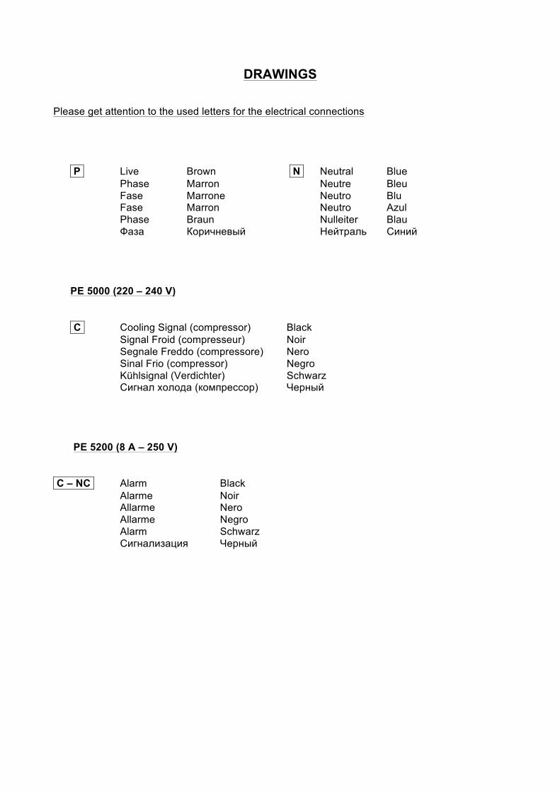
DRAWINGS Please get attention to the used letters for the electrical connections
P Live Brown N Neutral Blue Phase Marron Neutre Bleu Fase Marrone Neutro Blu Fase Marron Neutro Azul Phase Braun Nulleiter Blau Фаза Коричневый Нейтраль Синий PE 5000 (220 – 240 V) C Cooling Signal (compressor) Black
Signal Froid (compresseur) Noir Segnale Freddo (compressore) Nero Sinal Frio (compressor) Negro Kühlsignal (Verdichter) Schwarz Сигнал холода (компрессор) Черный
PE 5200 (8 A – 250 V)
C – NC Alarm Black
Alarme Noir Allarme Nero Allarme Negro Alarm Schwarz Сигнализация Черный
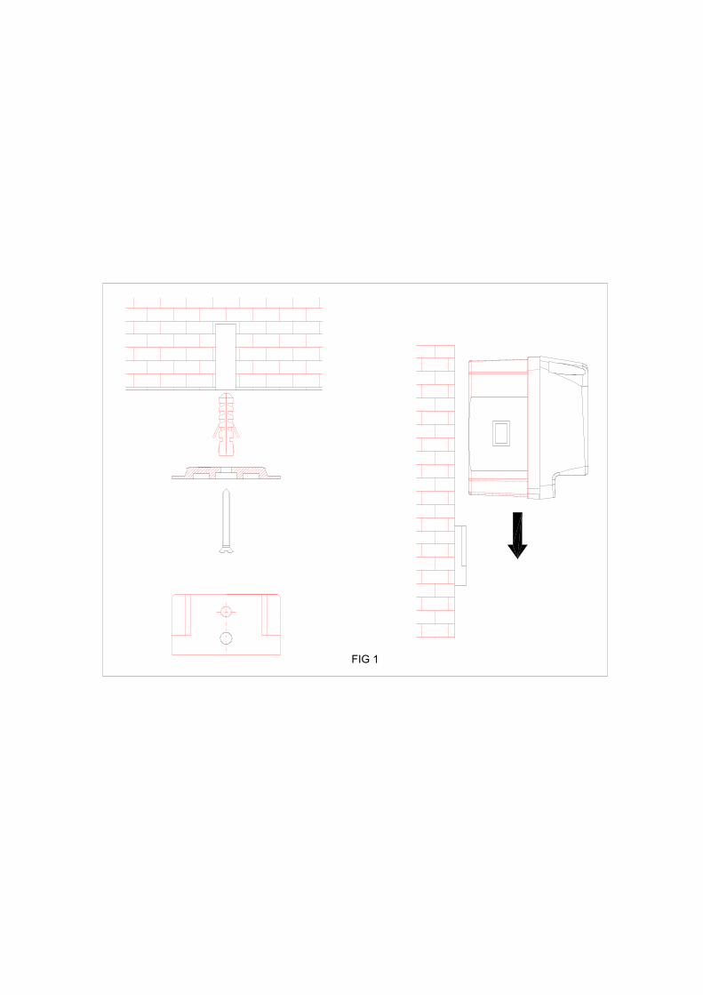
FIG 1
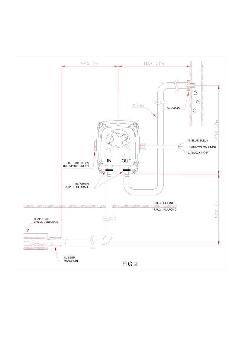
DRAIN TRAYBAC DE CONDESATS
RUBBERMANCHON
TEST BOTTON (3'')BOUTON DE TEST (3'')
TIE WRAPSCLIP DE SERRAGE
IN OUT
FALSE CEILING
FAUX - PLAFOND
N (BLUE-BLEU)
ACC00205
P (BROWN-MARRON)
C (BLACK-NOIR)
FIG 2
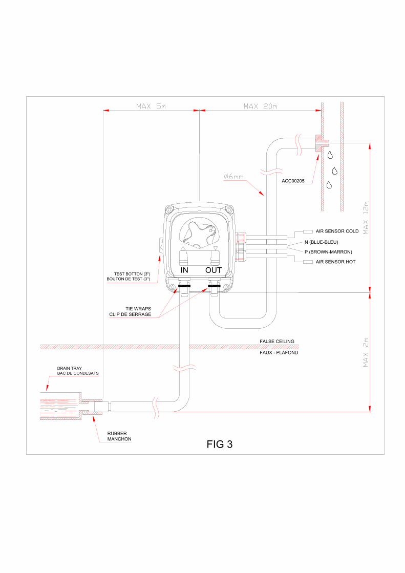
RUBBERMANCHON
TIE WRAPSCLIP DE SERRAGE
TEST BOTTON (3'')BOUTON DE TEST (3'')
DRAIN TRAYBAC DE CONDESATS
IN
FALSE CEILING
FAUX - PLAFOND
OUT
ACC00205
P (BROWN-MARRON)
N (BLUE-BLEU)
AIR SENSOR COLD
AIR SENSOR HOT
FIG 3
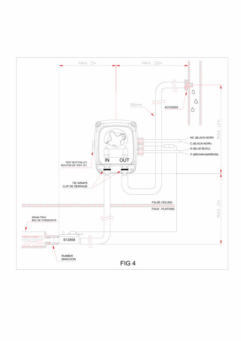
IN OUT
TIE WRAPSCLIP DE SERRAGE
S12858
RUBBERMANCHON
FALSE CEILING
FAUX - PLAFOND
ACC00205
TEST BOTTON (3'')BOUTON DE TEST (3'')
DRAIN TRAYBAC DE CONDESATS
N (BLUE-BLEU)
P (BROWN-MARRON)
C (BLACK-NOIR)
NC (BLACK-NOIR)
FIG 4
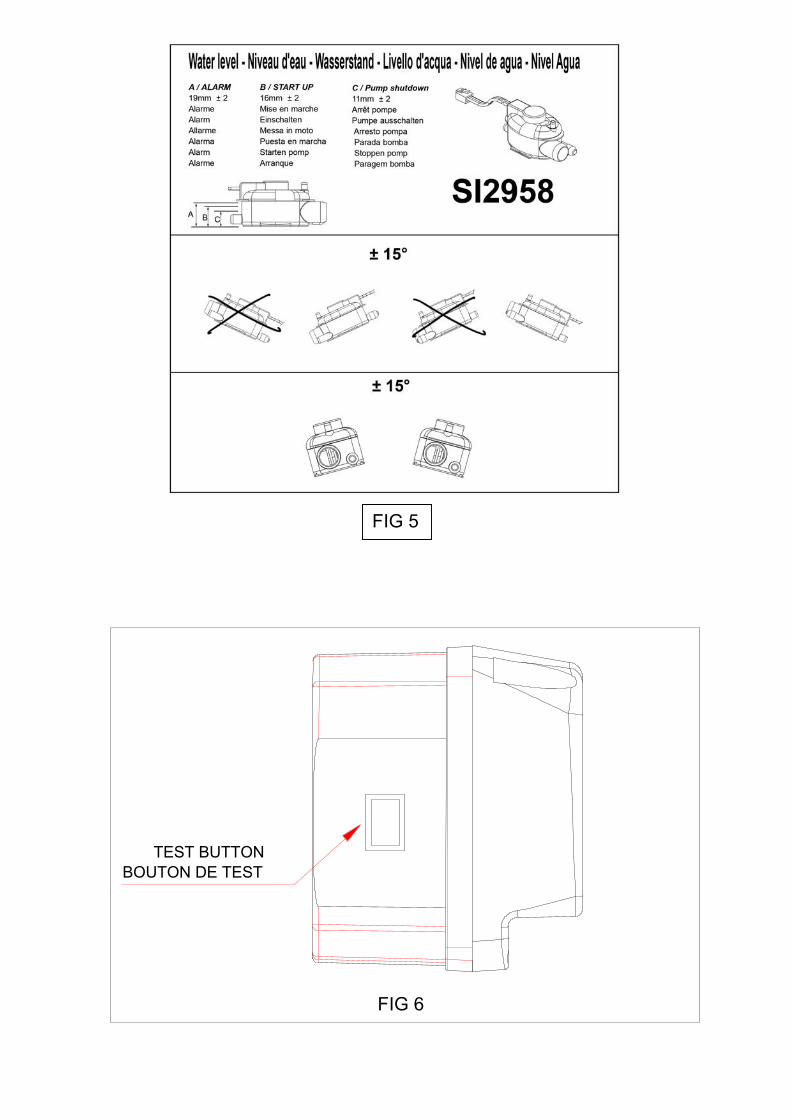
TEST BUTTON BOUTON DE TEST
FIG 6
FIG 5
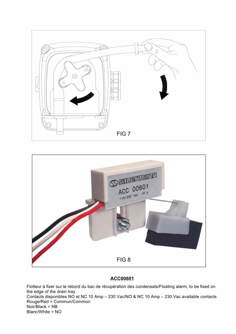
FIG 7
FIG 8
ACC00601
Flotteur à fixer sur le rebord du bac de récupération des condensats/Floating alarm, to be fixed on the edge of the drain tray Contacts disponibles NO et NC 10 Amp – 230 Vac/NO & NC 10 Amp – 230 Vac available contacts Rouge/Red = Commun/Common Noir/Black = NB Blanc/White = NO