Embed Size (px)
DESCRIPTION
Â
Citation preview
CHAUVIN ARNOUXTest et Mesure190, rue Championnet75876 PARIS Cedex 18 FRANCETél. : +33 1 44 85 44 85Fax : +33 1 46 27 73 [email protected]
PYROCONTROLE6 bis, av du Docteur Schweitzer69881 MEYZIEU Cedex FRANCETél. : +33 4 72 14 15 40Fax : +33 4 72 14 15 [email protected]
MANUMESURE45 route de Saint Eugène14130 REUX FRANCETél. : +33 2 31 64 51 00Fax : +33 2 31 64 51 [email protected]
10 SUBSIDIARIES WORLDWIDE
906
131
080
- Ed
. 9 -
05/
2015
- N
on-c
ontr
actu
al d
ocum
ent
- Sp
ecifi
catio
ns a
re t
o be
con
firm
ed a
t tim
e of
ord
erin
g -
Phot
os a
nd d
iagr
ams
are
non-
cont
ract
ual.
See the complete automation relays offering to meet all the requirements of industry, the energy sector, rail, etc.
AUSTRIAChauvin Arnoux Ges.m.b.HSlamastrasse 29/2/41230 WIENTel.: +43 1 61 61 9 61Fax: +43 1 61 61 9 [email protected] www.chauvin-arnoux.at
CHINAShanghai Pu-JiangEnerdis Instruments Co. Ltd3 Floor, Building 1 N° 381 Xiang De Road200081 SHANGHAITel.: +86 21 65 21 51 96Fax: +86 21 65 21 61 [email protected]
GERMANYChauvin Arnoux GmbHOhmstraße 177694 KEHL / RHEINTel.: +49 07851 99 26-0Fax: +49 07851 99 [email protected] www.chauvin-arnoux.de
ITALYAMRA SpAVia Sant’Ambrogio, 23 20846 MACHERIO (MB)Tel.: +39 039 245 75 45Fax: +39 039 481 [email protected] www.chauvin-arnoux.it
MIDDLE EASTChauvin Arnoux Middle EastPO Box 60-154 1241 2020 JAL EL DIB (Beirut) - LEBANONTel.: +961 1 890 425 Fax: +961 1 890 [email protected]
SPAINChauvin Arnoux Iberica SAC/ Roger de Flor N°293, 1a Planta08025 BARCELONATel.: +34 902 20 22 26Fax: +34 93 459 14 [email protected] www.chauvin-arnoux.es
SCANDINAVIA CA Mätsystem ABSjöflygvägen 35SE-183 62 TABYTel.: +46 8 50 52 68 00Fax: +46 8 50 52 68 [email protected]
SWITZERLANDChauvin Arnoux AGMoosacherstrasse 15 8804 AU / ZH Tel.: +41 44 727 75 55Fax: +41 44 727 75 [email protected] www.chauvin-arnoux.ch
UNITED KINGDOMChauvin Arnoux LtdUnit 1 Nelson Ct, Flagship Sq Shaw Cross Business Pk, DewsburyWest Yorkshire - WF12 7THTel:+44 1924 460 494 Fax: +44 1924 455 [email protected] www.chauvin-arnoux.com
USAChauvin Arnoux Inc d.b.a AEMC Instruments200 Foxborough Blvd. Foxborough - MA 02035Tel.: +1 (508) 698-2115Fax: +1 (508) [email protected] www.aemc.com
ENERDIS A local service for a better service
A centralized contact
ENERDIS16, rue Georges Besse - Silic 4492182 ANTONY CedexFRANCEwww.enerdis.com
FranceTel.: 01 75 60 10 30Fax: 01 46 66 62 [email protected]
InternationalTel.: +33 1 75 60 10 30 Fax: +33 1 46 66 62 [email protected]
Catalogue Pyro Capteurs 2013 GB.indd 1 13/02/2013 11:06:41
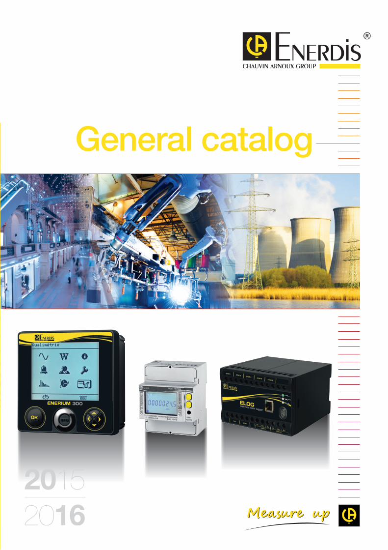
General catalog
2015/2015 Gen
eral
cat
alo
g 2
015-
2016
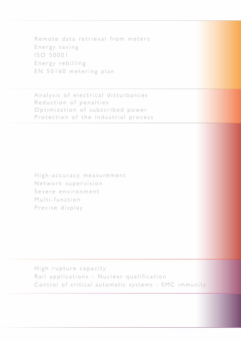
R e m o t e d a t a r e t r i e v a l f r o m m e t e r sE n e r g y s a v i n gI S O 5 0 0 0 1E n e r g y r e b i l l i n gE N 5 0 1 6 0 m e t e r i n g p l a n
A n a l y s i s o f e l e c t r i c a l d i s t u r b a n c e sR e d u c t i o n o f p e n a l t i e sO p t i m i z a t i o n o f s u b s c r i b e d p o w e rP r o t e c t i o n o f t h e i n d u s t r i a l p r o c e s s
H i g h r u p t u r e c a p a c i t yR a i l a p p l i c a t i o n s - N u c l e a r q u a l i f i c a t i o nC o n t r o l o f c r i t i c a l a u t o m a t i c s y s t e m s - E M C i m m u n i t y
H i g h - a c c u r a c y m e a s u r e m e n tN e t w o r k s u p e r v i s i o nS e v e r e e n v i r o n m e n tM u l t i - f u n c t i o nP r e c i s e d i s p l a y
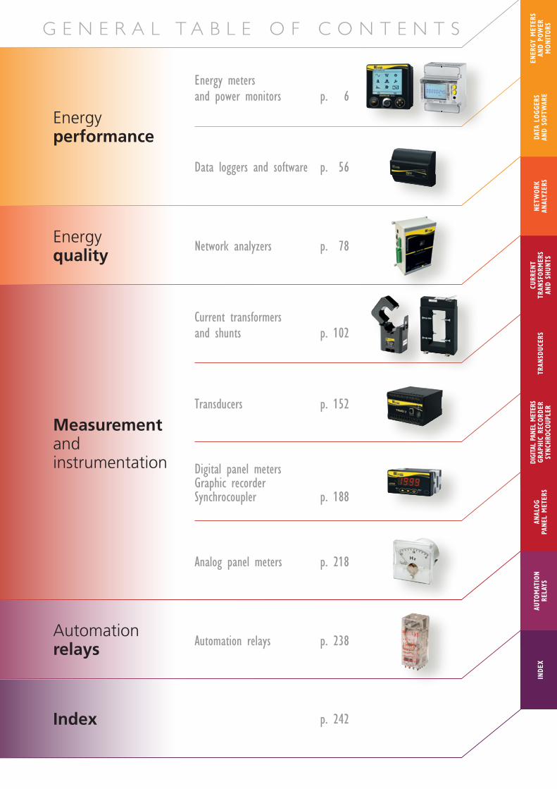
G E N E R A L T A B L E O F C O N T E N T S
Energy performance
Energy quality
Energy meters and power monitors p. 6
Data loggers and software p. 56
Network analyzers p. 78
Automation relays Automation relays p. 238
Measurement and instrumentation
Current transformers and shunts p. 102
Transducers p. 152
Digital panel metersGraphic recorderSynchrocoupler p. 188
Analog panel meters p. 218
Index
INDE
XAU
TOM
ATIO
N RE
LAYS
ANAL
OG
PANE
L M
ETER
S
CURR
ENT
TRAN
SFOR
MER
SAN
D SH
UNTS
DIGI
TAL
PANE
L M
ETER
SGR
APHI
C RE
CORD
ERSY
NCHR
OCOU
PLER
NETW
ORK
ANAL
YZER
STR
ANSD
UCER
SDA
TA L
OGGE
RS
AND
SOFT
WAR
E
ENER
GY M
ETER
S AN
D PO
WER
M
ONIT
ORS
p. 242

2
Founded in 1893 by Raphaël Chauvin and René Arnoux, CHAUVIN ARNOUX is an expert in measurement of electrical and physical quantities in the industrial and tertiary sectors.Total control of product design and manufacturing in-house enables the Group to propose its customers a very broad product and service offering which meets all their needs.The Group’s quality policy ensures that the products delivered comply with its commitments and with both the national and international standards in terms of metrology, the environment and user safety
About the CHAUVIN ARNOUX Group
> Th
e C
hauv
in A
rnou
x G
roup
and
Ene
rdis
A few figures
4 FRENCH COMPANIESpromoting the product and service offering
7 PRODUCTIONSITES3 in Normandy (France)1 in Lyon (France)1 in Milan (Italy)1 in Dover (USA)1 in Shanghai (China)
10 SUBSIDIARIES WORLDWIDEGermanyAustriaChinaSpainItalyLebanonSwedenSwitzerlandUnited KingdomUnited States
100 million euros in sales revenues
10 subsidiaries spread across the world
900 staff
7 production sites
6 R&D departments worldwide
11% of revenues invested in R&D
ChauvinArnoux
Portable Test& Measurement
instruments
ManumesureMetrology
& regulatorytesting
PyrocontroleTemperaturein industrialprocesses
EnerdisEnergy metering,measurementand monitoringequipment
CHAUVIN ARNOUX is a major force on the measurement market in France and internationally.

3
ENERDIS Chauvin Arnoux Group
Enerdis completes the Chauvin Arnoux Group’s global offering by designing permanent measuring equipment for electrical installations. Enerdis is a French company which is an expert in energy intelligence, specializing in fixed equipment for measurement, testing and supervision of electrical networks and energy systems.A precursor in energy management, Enerdis proposes global expertise from help with diagnostics through to the implementation of complete solutions (products, software and services) adapted to each type of environment (industrial, tertiary, building). These systems comply with the international regulatory and standardization framework.Its extensive offering of products and systems enables Enerdis to cover all the measurement requirements from the energy production site through to the point of consumption by integrating all the transmission networks and distribution systems.
Every year in the Engineering Department at Antony (France), where the company has its Head Office, innovative products are developed in fields such as metering (tariff meters or submeters), electrical network supervision and quality (power monitors, analyzers, etc.), communication systems and software to supervise energy flows.
• Energy performance• Power quality• Automation relays• Measurement and instrumentation
From energy supply through to its distribution on site
SOLUTIONS FOR EACH MEASUREMENT REQUIREMENT
FROM ELECTRICAL MEASUREMENT TO ENERGY PERFORMANCE MANAGEMENT
Industry
Production
Transmission
Railnetwork Tertiary
1 3 64
Automation relay
Meters
Power monitors
Transducers
E.online® solutions
Current transformers
Analogue panel meters
Digital panel meters
1
5
2
6
3
7
4
8
1 4
53 72 8
532
CHAUVIN ARNOUX is a major force on the measurement market in France and internationally.

Energy efficiency: the 4 phases of the approach>
Ener
gy p
erfo
rman
ce p
roje
ct
Measurement plays a key role in the definition, success and long-term performanceof an energy optimization approach.That’s why it is crucial not to skip any of the steps involved, which are applicable inthe context of:• an energy performance contract handled by an external service company• an “energy plan” handled in-house by company staff.
Chauvin Arnoux - One-off measurements
> Instruments for one-off measurements:wattmeter • infrared camera • light meter
> Instruments for measurement campaigns:network analyzer • infrared camera • light
meter • hygrometer • plug & play recorder
> Analyze energy bills in orderto identify:
• energy-hungry installations• production processes• the cost structure• the existing organization
> Acquire knowledge of the installation by one-off measurements so that you can determine the types of energy and utilities to be managed and the specific target (in €) to be reached.
> Analyze the behaviour of the installations very precisely by long-term measurement campaigns leading to a detailed audit which then serves as the reference for a Measurement and Verification Plan (MVP)
> Assess the potential energy savings and determine the minimum
requirements by: • improving the power factor • carrying out a power survey with
measurement of the energy consumed • searching for heat losses
DIAGNOSTICS1 DETAILED ANALYSIS2
4
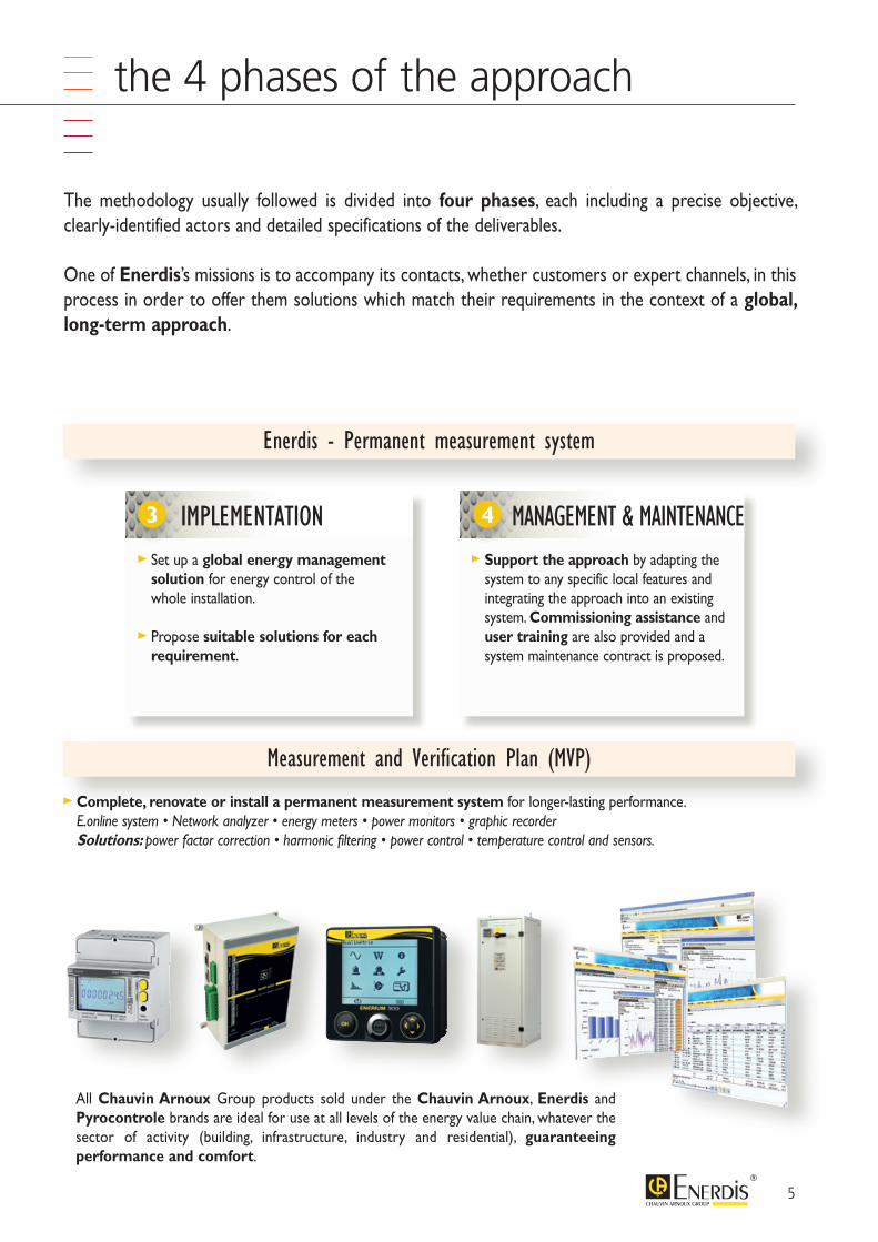
All Chauvin Arnoux Group products sold under the Chauvin Arnoux, Enerdis and Pyrocontrole brands are ideal for use at all levels of the energy value chain, whatever the sector of activity (building, infrastructure, industry and residential), guaranteeing performance and comfort.
Energy efficiency: the 4 phases of the approach
The methodology usually followed is divided into four phases, each including a precise objective, clearly-identified actors and detailed specifications of the deliverables.
One of Enerdis’s missions is to accompany its contacts, whether customers or expert channels, in this process in order to offer them solutions which match their requirements in the context of a global, long-term approach.
Enerdis - Permanent measurement system
Measurement and Verification Plan (MVP)
> Complete, renovate or install a permanent measurement system for longer-lasting performance. E.online system • Network analyzer • energy meters • power monitors • graphic recorder Solutions: power factor correction • harmonic filtering • power control • temperature control and sensors.
> Set up a global energy management solution for energy control of the whole installation.
> Propose suitable solutions for each requirement.
> Support the approach by adapting the system to any specific local features and integrating the approach into an existing system. Commissioning assistance and user training are also provided and a system maintenance contract is proposed.
IMPLEMENTATION3 MANAGEMENT & MAINTENANCE4
5
6
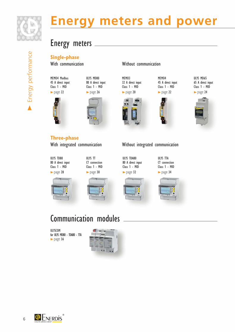
Energy meters and power monitors>
Ener
gy p
erfo
rman
ce
Energy meters
Communication modules
Single-phase With communication
Monophasés Without communication
ULYSCOM fur ULYS MD80 - TDA80 - TTA > page 36
ULYS MD80 80 A direct inputClass 1 - MID
> page 26
MEMO4 Modbus 45 A direct inputClass 1 - MID
> page 22
MEMO4 45 A direct inputClass 1 - MID
> page 22
ULYS MD65 65 A direct inputClass 1 - MID
> page 24
ULYS TDA80 80 A direct inputClass 1 - MID
> page 32
ULYS TTA CT connectionClass 1 - MID
> page 34
Three-phase With integrated communication
Triphasés Without integrated communication
ULYS TD80 80 A direct inputClass 1 - MID
> page 28
ULYS TT CT connectionClass 1 - MID
> page 30
MEMO3 32 A direct inputClass 1 - MID
> page 20
7
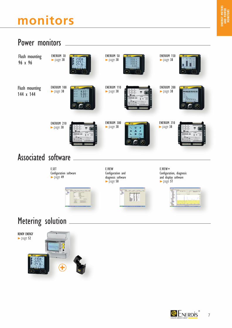
Energy meters and power monitors
Power monitors
Associated softwareE.SETConfiguration software > page 49
E.VIEW Configuration and diagnosis software > page 50
E.VIEW+ Configuration, diagnosis and display software > page 51
Flush mounting 96 x 96
ENERIUM 30 > page 38
ENERIUM 50 > page 38
ENERIUM 150 > page 38
Flush mounting 144 x 144
ENERIUM 100 > page 38
ENERIUM 110 > page 38
ENERIUM 200 > page 38
ENERIUM 210 > page 38
ENERIUM 300 > page 38
ENERIUM 310 > page 38
Metering solutionRENOV ENERGY > page 52
ENER
GY M
ETER
S AN
D PO
WER
M
ONIT
ORS
8
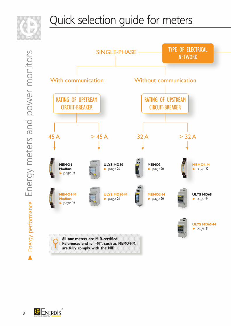
Quick selection guide for meters>
Ener
gy p
erfo
rman
ce E
nerg
y m
eter
s an
d po
wer
mon
itors
TYPE OF ELECTRICAL NETWORK
SINGLE-PHASE
With communication Without communication
RATING OF UPSTREAMCIRCUIT-BREAKER
RATING OF UPSTREAMCIRCUIT-BREAKER
> 32 A32 A45 A > 45 A
MEMO4 Modbus > page 22
MEMO4-M Modbus > page 22
ULYS MD80 > page 26
ULYS MD80-M > page 26
MEMO3 > page 20
MEMO3-M > page 20
MEMO4-M > page 22
ULYS MD65 > page 24
ULYS MD65-M > page 24
All our meters are MID-certified. References end is "-M", such as MEMO4-M, are fully comply with the MID.
9
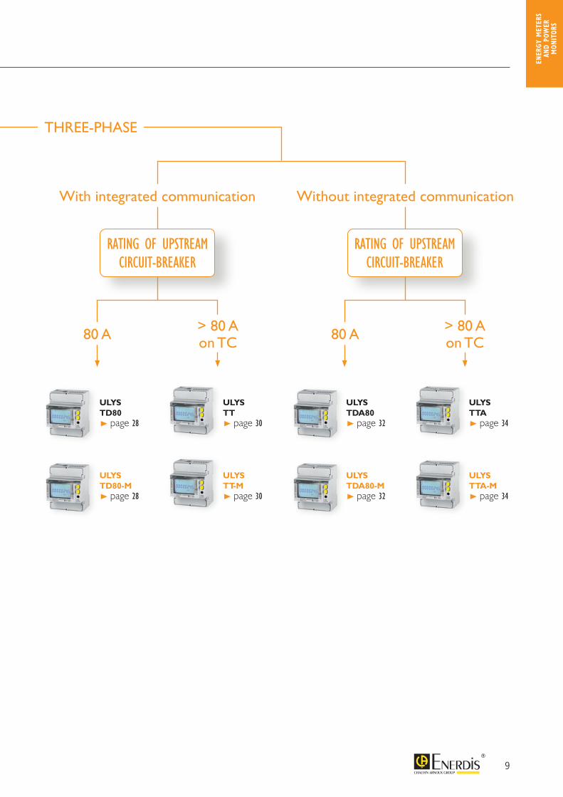
Quick selection guide for meters
THREE-PHASE
With integrated communication Without integrated communication
80 A80 A > 80 Aon TC
> 80 Aon TC
RATING OF UPSTREAMCIRCUIT-BREAKER
RATING OF UPSTREAMCIRCUIT-BREAKER
ULYS TDA80 > page 32
ULYS TDA80-M > page 32
ULYS TD80 > page 28
ULYS TD80-M > page 28
ULYS TTA > page 34
ULYS TTA-M > page 34
ULYS TT > page 30
ULYS TT-M > page 30
ENER
GY M
ETER
S AN
D PO
WER
M
ONIT
ORS
10
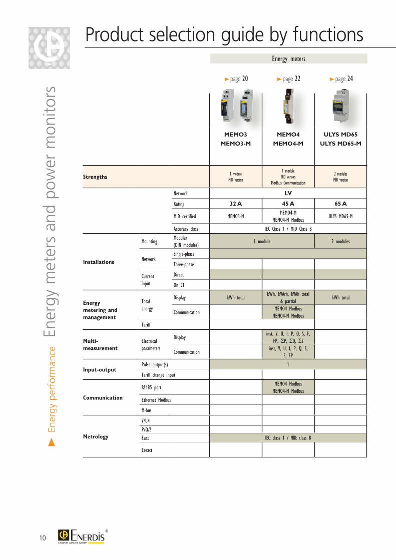
Product selection guide by functions
MEMO3
MEMO3-M
MEMO4
MEMO4-M
ULYS MD65
ULYS MD65-M
ULYS MD80
ULYS MD80-M
ULYS TDA80
ULYS TDA80-M
ULYS TTA
ULYS TTA-M
ULYS TD80
ULYS TD80-M
ULYS TT
ULYS TT-M
Strengths 1 moduleMID version
1 moduleMID version
Modbus Communication
2 modulesMID version
Multi-communication protocolsMulti-measurement
MID version
Multi-communication protocolsMulti-measurement
MID version
Multi-communication protocolsMulti-measurement
MID version
4 modulesIntegrated communication
MID version
4 modulesIntegrated communication
MID version
Network LV LV
Rating 32 A 45 A 65 A 80 A on CT 80 A on CT
MID certified MEMO3-MMEMO4-M
MEMO4-M ModbusULYS MD65-M ULYS MD80-M ULYS TDA80-M ULYS TTA-M ULYS TD80-M ULYS TT-M
Accuracy class IEC Class 1 / MID Class B IEC class 1 / MID class B
Installations
MountingModular (DIN modules)
1 module 2 modules 2 modules 4 modules
NetworkSingle-phase
Three-phase 3/4 wires 3/4 wires*
Current input
Direct
On CT Insulated Insulated
Energy metering and management
Total energy
Display kWh totalkWh, kVArh, kVAh total
& partialkWh total
kWh, kVArh, kVAh total & partialkWh, kVArh, kVAh total & partial
CommunicationMEMO4 Modbus
MEMO4-M Modbus
Tariff 2 tariffs 2 tariffs
Multi-measurement
Electrical parameters
Displayinst, V, U, I, P, Q, S, F,
FP, ΣP, ΣQ, ΣSinst, V, U, I, P, Q, S, F, FP, ΣP, ΣQ, ΣS inst, V, U, I, P, Q, S, F, FP, ΣP, ΣQ, ΣS
Communicationinst, V, U, I, P, Q, S,
F, FPinst, V, U, I, P, Q, S, F, FP inst, V, U, I, P, Q, S, F, FP, ΣP, ΣQ, ΣS inst, V, U, I, P, Q, S, F, FP, ΣP, ΣQ, ΣS
Input-outputPulse output(s) 1 2 1
Tariff change input 1 1*
Communication
RS485 portMEMO4 Modbus
MEMO4-M Modbusvia ULYSCOM communication modules
ULYS TD80 Modbus / -M ULYS TT Modbus / -M
Ethernet Modbus ULYS TD80 Ethernet / -M ULYS TT Ethernet / -M
M-bus ULYS TD80 M-bus / -M ULYS TT M-bus / -M
Metrology
V/U/I 0,5 %
P/Q/S 1 %Eact IEC: class 1 / MID: class B IEC: class 1 / MID: class B
Ereact IEC: class 2
Energy meters
> page 20 > page 22 > page 24
> En
ergy
per
form
ance E
nerg
y m
eter
s an
d po
wer
mon
itors
11
Product selection guide by functions
MEMO3
MEMO3-M
MEMO4
MEMO4-M
ULYS MD65
ULYS MD65-M
ULYS MD80
ULYS MD80-M
ULYS TDA80
ULYS TDA80-M
ULYS TTA
ULYS TTA-M
ULYS TD80
ULYS TD80-M
ULYS TT
ULYS TT-M
Strengths 1 moduleMID version
1 moduleMID version
Modbus Communication
2 modulesMID version
Multi-communication protocolsMulti-measurement
MID version
Multi-communication protocolsMulti-measurement
MID version
Multi-communication protocolsMulti-measurement
MID version
4 modulesIntegrated communication
MID version
4 modulesIntegrated communication
MID version
Network LV LV
Rating 32 A 45 A 65 A 80 A on CT 80 A on CT
MID certified MEMO3-MMEMO4-M
MEMO4-M ModbusULYS MD65-M ULYS MD80-M ULYS TDA80-M ULYS TTA-M ULYS TD80-M ULYS TT-M
Accuracy class IEC Class 1 / MID Class B IEC class 1 / MID class B
Installations
MountingModular (DIN modules)
1 module 2 modules 2 modules 4 modules
NetworkSingle-phase
Three-phase 3/4 wires 3/4 wires*
Current input
Direct
On CT Insulated Insulated
Energy metering and management
Total energy
Display kWh totalkWh, kVArh, kVAh total
& partialkWh total
kWh, kVArh, kVAh total & partialkWh, kVArh, kVAh total & partial
CommunicationMEMO4 Modbus
MEMO4-M Modbus
Tariff 2 tariffs 2 tariffs
Multi-measurement
Electrical parameters
Displayinst, V, U, I, P, Q, S, F,
FP, ΣP, ΣQ, ΣSinst, V, U, I, P, Q, S, F, FP, ΣP, ΣQ, ΣS inst, V, U, I, P, Q, S, F, FP, ΣP, ΣQ, ΣS
Communicationinst, V, U, I, P, Q, S,
F, FPinst, V, U, I, P, Q, S, F, FP inst, V, U, I, P, Q, S, F, FP, ΣP, ΣQ, ΣS inst, V, U, I, P, Q, S, F, FP, ΣP, ΣQ, ΣS
Input-outputPulse output(s) 1 2 1
Tariff change input 1 1*
Communication
RS485 portMEMO4 Modbus
MEMO4-M Modbusvia ULYSCOM communication modules
ULYS TD80 Modbus / -M ULYS TT Modbus / -M
Ethernet Modbus ULYS TD80 Ethernet / -M ULYS TT Ethernet / -M
M-bus ULYS TD80 M-bus / -M ULYS TT M-bus / -M
Metrology
V/U/I 0,5 %
P/Q/S 1 %Eact IEC: class 1 / MID: class B IEC: class 1 / MID: class B
Ereact IEC: class 2
Energy meters
> page 26 > page 32 > page 34 > page 28 > page 30
* depending on model
ENER
GY M
ETER
S AN
D PO
WER
M
ONIT
ORS
12
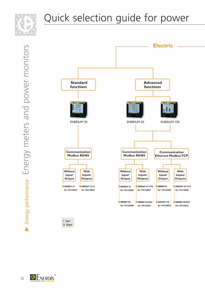
Quick selection guide for power monitors
ENERIUM 30
Electric
Standardfunctions
Communication Modbus RS485
Without Input/
Output
With Inputs/
Outputs
ENERIUM 30
Ref. P01330823
ENERIUM 30 1 O
Ref. P01330824
ENERIUM 50 ENERIUM 150
Advancedfunctions
Communication Modbus RS485
Without Input/
Output
With Inputs/
Outputs
Without Input/
Output
With Inputs/
Outputs
Communication Ethernet Modbus TCP
ENERIUM 50
Ref. P01330805
ENERIUM 150
Ref. P01330809
ENERIUM 50 1I/1O
Ref. P01330807
ENERIUM 150 0 I/2 O
Ref. P01330811
ENERIUM 50
Ref. P01330806
ENERIUM 150
Ref. P01330810
ENERIUM 50 1I/1O
Ref. P01330808
ENERIUM 150 0 I/2 O
Ref. P01330812
> En
ergy
per
form
ance E
nerg
y m
eter
s an
d po
wer
mon
itors
I: InputO: Output
13
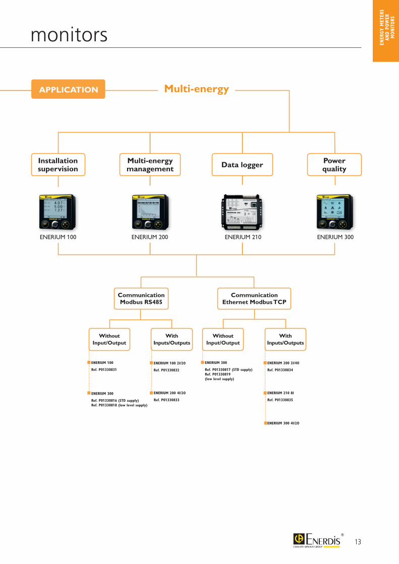
Quick selection guide for power monitors
Multi-energy
ENERIUM 200ENERIUM 100 ENERIUM 210 ENERIUM 300
Installationsupervision
Multi-energymanagement Data logger Power
quality
Without Input/Output
Without Input/Output
With Inputs/Outputs
With Inputs/Outputs
Communication Modbus RS485
Communication Ethernet Modbus TCP
ENERIUM 300 Ref. P01330817 (STD supply)Ref. P01330819 (low level supply)
ENERIUM 100 2I/2O
Ref. P01330832
ENERIUM 200 4I/2O
Ref. P01330833
ENERIUM 100 Ref. P01330831
ENERIUM 300 Ref. P01330816 (STD supply)Ref. P01330818 (low level supply)
ENERIUM 200 2I/4O
Ref. P01330834
ENERIUM 300 4I/2O
ENERIUM 210 8I
Ref. P01330835
APPLICATION
ENER
GY M
ETER
S AN
D PO
WER
M
ONIT
ORS
14
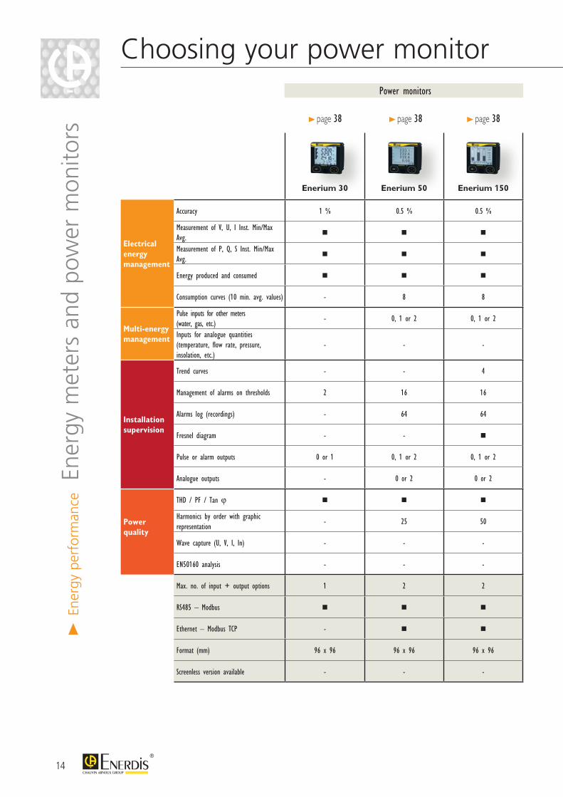
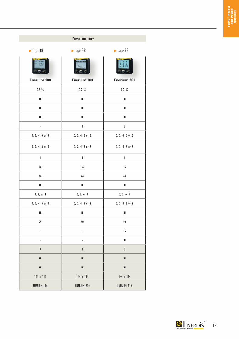
Choosing your power monitor
Enerium 30 Enerium 50 Enerium 150 Enerium 100 Enerium 200 Enerium 300
Electrical energy management
Accuracy 1 % 0.5 % 0.5 % 0.5 % 0.2 % 0.2 %
Measurement of V, U, I Inst. Min/MaxAvg.
Measurement of P, Q, S Inst. Min/Max Avg.
Energy produced and consumed
Consumption curves (10 min. avg. values) - 8 8 - 8 8
Multi-energy management
Pulse inputs for other meters (water, gas, etc.)
- 0, 1 or 2 0, 1 or 2 0, 2, 4, 6 or 8 0, 2, 4, 6 or 8 0, 2, 4, 6 or 8
Inputs for analogue quantities(temperature, flow rate, pressure, insolation, etc.)
- - - 0, 2, 4, 6 or 8 0, 2, 4, 6 or 8 0, 2, 4, 6 or 8
Installation supervision
Trend curves - - 4 4 4 4
Management of alarms on thresholds 2 16 16 16 16 16
Alarms log (recordings) - 64 64 64 64 64
Fresnel diagram - -
Pulse or alarm outputs 0 or 1 0, 1 or 2 0, 1 or 2 0, 2, or 4 0, 2, or 4 0, 2, or 4
Analogue outputs - 0 or 2 0 or 2 0, 2, 4, 6 or 8 0, 2, 4, 6 or 8 0, 2, 4, 6 or 8
Power quality
THD / PF / Tan ϕ
Harmonics by order with graphic representation
- 25 50 25 50 50
Wave capture (U, V, I, In) - - - - - 16
EN50160 analysis - - - - -
Max. no. of input + output options 1 2 2 8 8 8
RS485 – Modbus
Ethernet – Modbus TCP -
Format (mm) 96 x 96 96 x 96 96 x 96 144 x 144 144 x 144 144 x 144
Screenless version available - - - ENERIUM 110 ENERIUM 210 ENERIUM 310
Power monitors
> page 38 > page 38 > page 38
> En
ergy
per
form
ance E
nerg
y m
eter
s an
d po
wer
mon
itors
15
Choosing your power monitor
Enerium 30 Enerium 50 Enerium 150 Enerium 100 Enerium 200 Enerium 300
Electrical energy management
Accuracy 1 % 0.5 % 0.5 % 0.5 % 0.2 % 0.2 %
Measurement of V, U, I Inst. Min/MaxAvg.
Measurement of P, Q, S Inst. Min/Max Avg.
Energy produced and consumed
Consumption curves (10 min. avg. values) - 8 8 - 8 8
Multi-energy management
Pulse inputs for other meters (water, gas, etc.)
- 0, 1 or 2 0, 1 or 2 0, 2, 4, 6 or 8 0, 2, 4, 6 or 8 0, 2, 4, 6 or 8
Inputs for analogue quantities(temperature, flow rate, pressure, insolation, etc.)
- - - 0, 2, 4, 6 or 8 0, 2, 4, 6 or 8 0, 2, 4, 6 or 8
Installation supervision
Trend curves - - 4 4 4 4
Management of alarms on thresholds 2 16 16 16 16 16
Alarms log (recordings) - 64 64 64 64 64
Fresnel diagram - -
Pulse or alarm outputs 0 or 1 0, 1 or 2 0, 1 or 2 0, 2, or 4 0, 2, or 4 0, 2, or 4
Analogue outputs - 0 or 2 0 or 2 0, 2, 4, 6 or 8 0, 2, 4, 6 or 8 0, 2, 4, 6 or 8
Power quality
THD / PF / Tan ϕ
Harmonics by order with graphic representation
- 25 50 25 50 50
Wave capture (U, V, I, In) - - - - - 16
EN50160 analysis - - - - -
Max. no. of input + output options 1 2 2 8 8 8
RS485 – Modbus
Ethernet – Modbus TCP -
Format (mm) 96 x 96 96 x 96 96 x 96 144 x 144 144 x 144 144 x 144
Screenless version available - - - ENERIUM 110 ENERIUM 210 ENERIUM 310
Power monitors
> page 38 > page 38 > page 38
ENER
GY M
ETER
S AN
D PO
WER
M
ONIT
ORS

16
Info & advice
WHAT IS THE MID? The MID (Measuring Instruments Directive - 2004/22/CE) is a European Directive issued in 2004 which applies to devices and systems with a measuring function in order to protect the interests of consumers, particularly in the context of commercial transactions. These measuring instruments may be active electrical energy meters (Annex MI003 of the Directive), water, gas or heat meters, weighing instruments, etc.
Scope The MID covers three types of usage: “Measurements of residential, commercial and light industrial use”. A mini-mum meter accuracy class is imposed for each usage category as stipulated in the Directive 2004/22/CE:
Where a Member State imposes measurement of residential use, it shall allow such measurement to be performed by means of any Class A meter. For specified purposes the Member State is authorized to require any Class B meter.
Where a Member State imposes measurement of commercial and/or light industrial use, it shall allow such measurement to be performed by any Class B meter. For specified purposes the Member State is authorized to require any Class C meter.
The MID does not however apply to “Energy meters on which the [Ph-Ph] voltage between the connection terminals exceeds 600 V”
Regulatory Context
European directive on measuring instruments dated 31st March 2004
Directive transposed into national law of each country in 2006
2 specific European standards (EN 50470-1/ EN 50470-3) for energy meters, stipulating the particular requirements and type tests for energy meters
> En
ergy
per
form
ance E
nerg
y m
eter
s an
d po
wer
mon
itors
17
1 Downstream of the meter at the network manager’s point of supply.
CONDITIONS OF APPLICATION
ACCURACY CLASSES AND METER IDENTIFICATION
THE ENERDIS PRODUCTS CONCERNED
In the European Union, the use of MID-certified meters on “private”(1) electrical networks has been made mandatory in the context of active energy billing based on consumption readings by index differences.
Typical examples include: camping sites, holiday rentals, student accommodation, office buildings, shopping centres, marinas, exhibition halls, electric vehicle recharging stations, etc.
As the MID is applicable to all European Union Member States, certification of ammeter by a Notified Body (NB) means that no other testing by a national legal metrological service is required. So a MID-certified Enerdis meter can be used as an active energy billing meter in all European Union countries.
The Directive also imposes product certification according to the EN50470-1/-3 standard, as well as design certification (Module B) and manufacturing process certification (Module D) by a Notified Body, in order to ensure product traceability and guarantee its metrological value, thus helping to protect consumers.
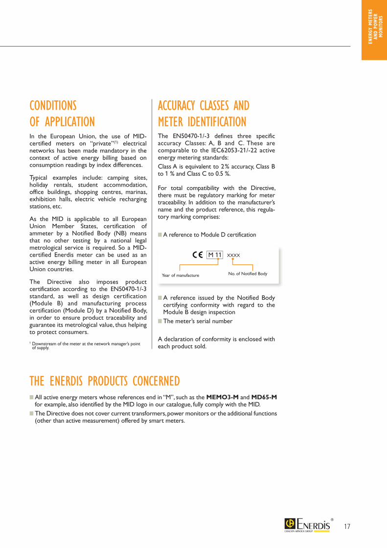
The EN50470-1/-3 defines three specific accuracy Classes: A, B and C. These are comparable to the IEC62053-21/-22 active energy metering standards: Class A is equivalent to 2 % accuracy, Class B to 1 % and Class C to 0.5 %.
For total compatibility with the Directive, there must be regulatory marking for meter traceability. In addition to the manufacturer’s name and the product reference, this regula-tory marking comprises:
A reference to Module D certification
A reference issued by the Notified Body certifying conformity with regard to the Module B design inspection
The meter’s serial number
A declaration of conformity is enclosed with each product sold.
All active energy meters whose references end in “M”, such as the MEMO3-M and MD65-M for example, also identified by the MID logo in our catalogue, fully comply with the MID.
The Directive does not cover current transformers, power monitors or the additional functions (other than active measurement) offered by smart meters.
XXXX
Year of manufacture No. of Notified Body
M 11
ENER
GY M
ETER
S AN
D PO
WER
M
ONIT
ORS
18
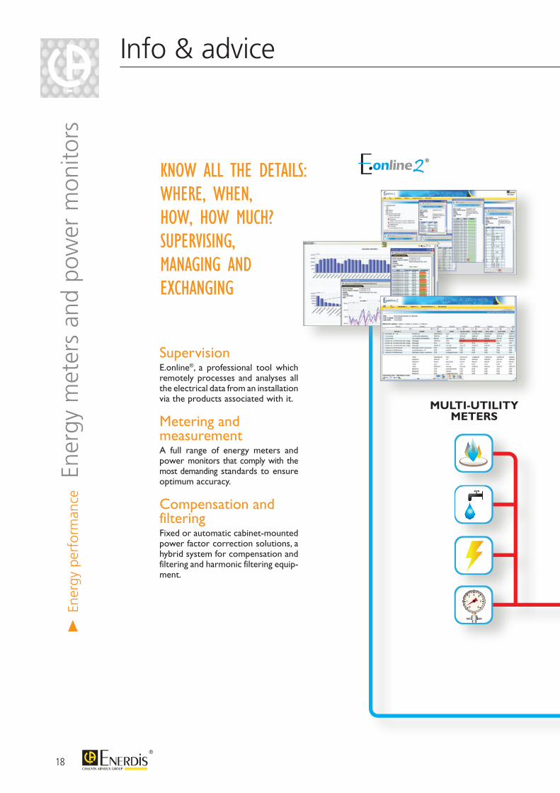
Supervision E.online®, a professional tool which remotely processes and analyses all the electrical data from an installation via the products associated with it.
Metering and measurement A full range of energy meters and power monitors that comply with the most demanding standards to ensure optimum accuracy.
Compensation and filtering Fixed or automatic cabinet-mounted power factor correction solutions, a hybrid system for compensation and filtering and harmonic filtering equip-ment.
KNOW ALL THE DETAILS: WHERE, WHEN, HOW, HOW MUCH?SUPERVISING, MANAGING AND EXCHANGING
Info & advice
0
1 5
32 4
6
MULTI-UTILITY METERS
> En
ergy
per
form
ance E
nerg
y m
eter
s an
d po
wer
mon
itors
19
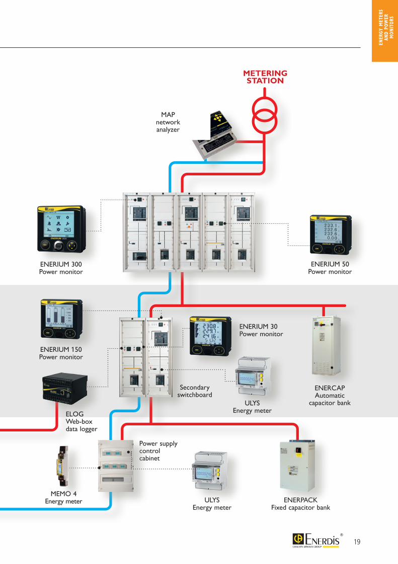
Power supplycontrolcabinet
0
1 5
32 4
6
TGBT
ENERCAPAutomatic
capacitor bank
METERINGSTATION
ENERPACKFixed capacitor bank
ENERIUM 30 Power monitor
Secondaryswitchboard
ENERIUM 300 Power monitor
ENERIUM 50Power monitor
ENERIUM 150 Power monitor
ULYSEnergy meter
ULYSEnergy meter
MEMO 4Energy meter
ELOG Web-boxdata logger
MAP network analyzer
ENER
GY M
ETER
S AN
D PO
WER
M
ONIT
ORS

20
MID certification Sealable terminal covers
Backlit LCD permanent display for easy reading in low-lighting environments
Pulse output as standard
MEMO 3 is the economical solution from ENERDIS for monitoring the electricity consumption of customers on single-phase 230 V networks. Equipped with mechanical display, the MEMO 3 offers Class 1 accuracy, in total compliance with IEC standard 62053-21.
MEMO 3-M is the perfectly adapted solution for rebilling electricity on private network. Fully compliant with MID standard, MEMO 3-M energy meter is dedicated to electricity commercial applications as campsites, marinas, holiday rentals and outdoor accommodation facilities:- DIN rail mounting with direct connection for 32 A network- Sealable cover (phase and neutral terminals)- Pulse output as standard
Associated with E.online® energy management software, it offers remote processing of energy consumption via PC, thus enabling you to produce consumption reports automatically and establish an accurate breakdown of the energies consumed.
MEMO 3 single-phase 32 AEnergy meters for single-phase networks32 A direct connection
> En
ergy
per
form
ance E
nerg
y m
eter
s
PRODUCT ADVANTAGES
32 A nominal current
CLASS 1 according to IEC 62053-21 MID CLASS B according to EN50470-3
COMPACT: a single DIN module
PULSE OUTPUT as standard
SEALABLE on phase and neutral terminals
> Description
21
CHARGE
> Dimensions (in mm)
> Electrical connections
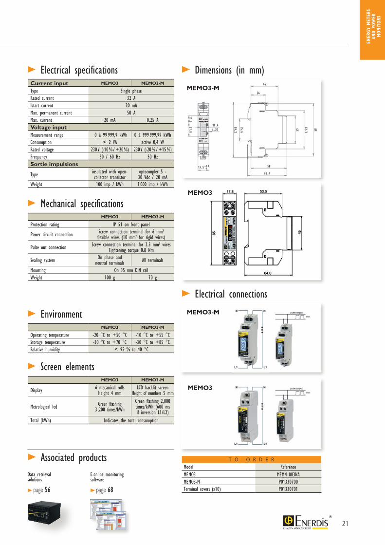
> Electrical specificationsCurrent input MEMO3 MEMO3-M
Type Single phase Rated current 32 AIstart current 20 mAMax. permanent current 50 AMax. current 20 mA 0,25 AVoltage inputMeasurement range 0 à 99 999,9 kWh 0 à 999 999,99 kWhConsumption < 2 VA active 0,4 WRated voltage 230 V (-10 % / +20 %) 230 V (-20 % / +15 %)Frequency 50 / 60 Hz 50 HzSortie impulsions
Type insulated with open-collector transistor
optocoupler 5 - 30 Vdc / 20 mA
Weight 100 imp / kWh 1 000 imp / kWh
> EnvironmentMEMO3 MEMO3-M
Operating temperature -20 °C to +50 °C -10 °C to +55 °CStorage temperature -30 °C to +70 °C -30 °C to +85 °CRelative humidity < 95 % to 40 °C
> Screen elementsMEMO3 MEMO3-M
Display 6 mecanical rolls Height 4 mm
LCD backlit screen Height of numbers 5 mm
Metrological led Green flashing 3 ,200 times/kWh
Green flashing 2,000 times/kWh (600 ms if inversion L1/L2)
Total (kWh) Indicates the total consumption
MEMO3 MEMO3-M
Protection rating IP 51 on front panel
Power circuit connection Screw connection terminal for 6 mm² flexible wires (10 mm² for rigid wires)
Pulse out connection Screw connection terminal for 2.5 mm² wires Tightening torque 0.8 Nm
Sealing system On phase and neutral terminals All terminals
Mounting On 35 mm DIN railWeight 100 g 70 g
> Mechanical specifications
MEMO3-M
MEMO3
Model ReferenceMEMO3 MEMN 003NAMEMO3-M P01330700Terminal covers (x10) P01330701
T O O R D E R
MEMO3
MEMO3-M
> Associated productsData retrieval solutions
> page 56
E.online monitoring software
> page 68
ENER
GY M
ETER
S AN
D PO
WER
M
ONIT
ORS
22
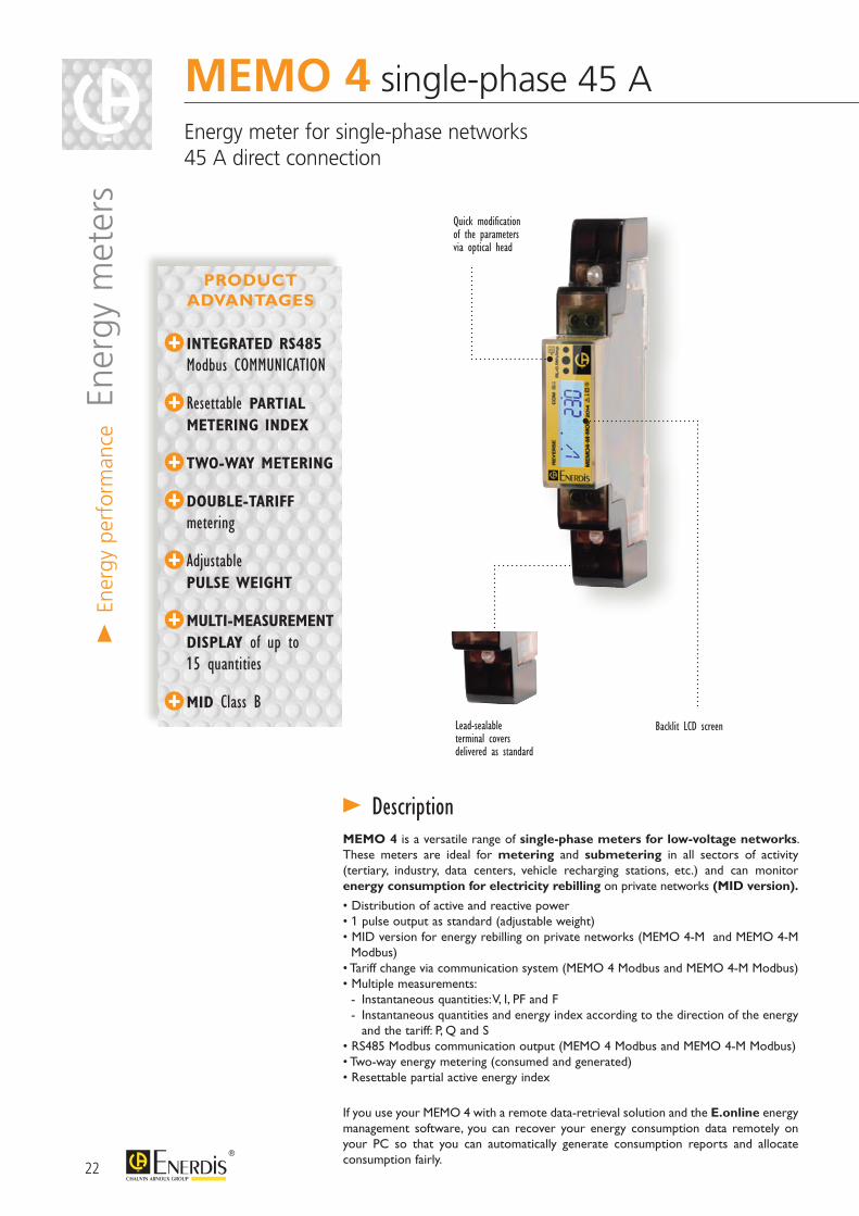
Lead-sealable terminal covers delivered as standard
Backlit LCD screen
Quick modification of the parameters via optical head
MEMO 4 is a versatile range of single-phase meters for low-voltage networks. These meters are ideal for metering and submetering in all sectors of activity (tertiary, industry, data centers, vehicle recharging stations, etc.) and can monitor energy consumption for electricity rebilling on private networks (MID version).
• Distribution of active and reactive power• 1 pulse output as standard (adjustable weight)• MID version for energy rebilling on private networks (MEMO 4-M and MEMO 4-M Modbus)• Tariff change via communication system (MEMO 4 Modbus and MEMO 4-M Modbus)• Multiple measurements: - Instantaneous quantities: V, I, PF and F - Instantaneous quantities and energy index according to the direction of the energy and the tariff: P, Q and S• RS485 Modbus communication output (MEMO 4 Modbus and MEMO 4-M Modbus)• Two-way energy metering (consumed and generated)• Resettable partial active energy index
If you use your MEMO 4 with a remote data-retrieval solution and the E.online energy management software, you can recover your energy consumption data remotely on your PC so that you can automatically generate consumption reports and allocate consumption fairly.
> Description
MEMO 4 single-phase 45 A Energy meter for single-phase networks 45 A direct connection
PRODUCT ADVANTAGES
INTEGRATED RS485 Modbus COMMUNICATION
Resettable PARTIAL METERING INDEX
TWO-WAY METERING
DOUBLE-TARIFF metering
Adjustable PULSE WEIGHT
MULTI-MEASUREMENT DISPLAY of up to 15 quantities
MID Class B
> En
ergy
per
form
ance E
nerg
y m
eter
s
23
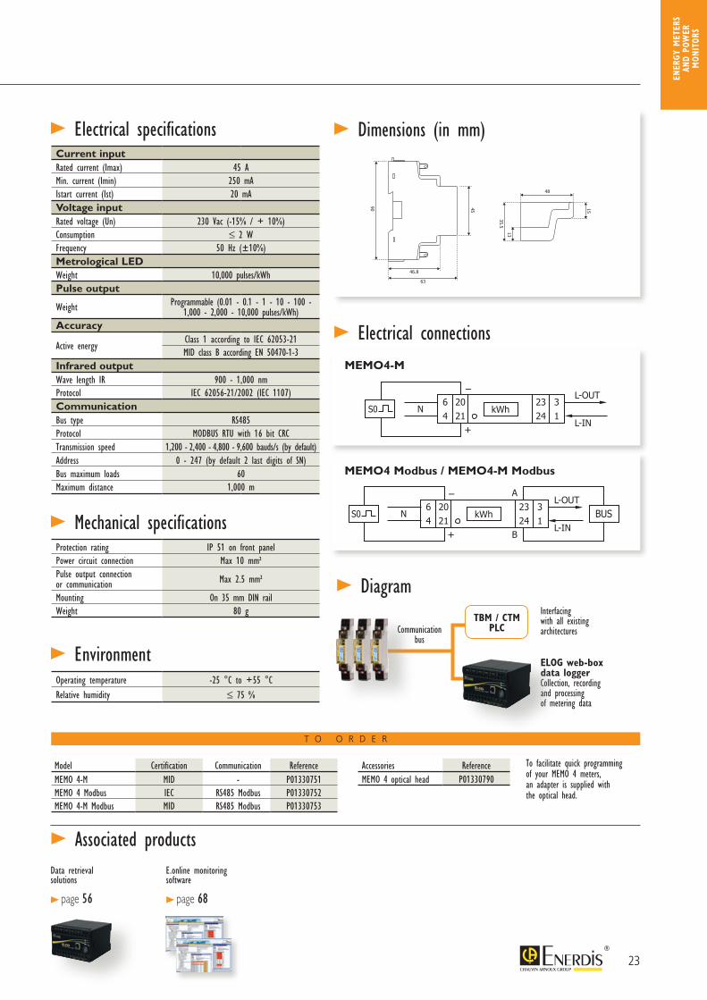
> Electrical connections
> Diagram
46.8
63
48
15
90 45
13
35.5
+
64
2324
2021
31
L-IN
L-OUTNS0 kWh
MEMO4-M
> Dimensions (in mm) > Electrical specificationsCurrent inputRated current (Imax) 45 AMin. current (Imin) 250 mAIstart current (Ist) 20 mAVoltage inputRated voltage (Un) 230 Vac (-15% / + 10%)Consumption ≤ 2 WFrequency 50 Hz (±10%)Metrological LEDWeight 10,000 pulses/kWhPulse output
Weight Programmable (0.01 - 0.1 - 1 - 10 - 100 - 1,000 - 2,000 - 10,000 pulses/kWh)
Accuracy
Active energyClass 1 according to IEC 62053-21MID class B according EN 50470-1-3
Infrared outputWave length IR 900 - 1,000 nmProtocol IEC 62056-21/2002 (IEC 1107)CommunicationBus type RS485Protocol MODBUS RTU with 16 bit CRCTransmission speed 1,200 - 2,400 - 4,800 - 9,600 bauds/s (by default)Address 0 - 247 (by default 2 last digits of SN)Bus maximum loads 60Maximum distance 1,000 m
> EnvironmentOperating temperature -25 °C to +55 °CRelative humidity ≤ 75 %
Protection rating IP 51 on front panelPower circuit connection Max 10 mm² Pulse output connection or communication Max 2.5 mm²
Mounting On 35 mm DIN railWeight 80 g
> Mechanical specifications
To facilitate quick programming of your MEMO 4 meters, an adapter is supplied with the optical head.
Model Certification Communication ReferenceMEMO 4-M MID - P01330751MEMO 4 Modbus IEC RS485 Modbus P01330752MEMO 4-M Modbus MID RS485 Modbus P01330753
T O O R D E R
Accessories ReferenceMEMO 4 optical head P01330790
+
64
2324
2021
A
B
31
L-IN
L-OUTNS0 kWh BUS
MEMO4 Modbus / MEMO4-M Modbus
46.8
63
48
15
90 45
13
35.5
Communication bus
Interfacing with all existing architectures
ELOG web-box data loggerCollection, recording and processing of metering data
TBM / CTM PLC
> Associated productsData retrieval solutions
> page 56
E.online monitoring software
> page 68
ENER
GY M
ETER
S AN
D PO
WER
M
ONIT
ORS
24
> En
ergy
per
form
ance E
nerg
y m
eter
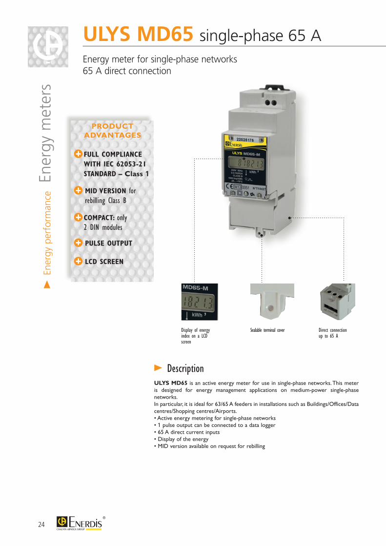
sULYS MD65 single-phase 65 A Energy meter for single-phase networks65 A direct connection
Display of energy index on a LCD screen
Sealable terminal cover
ULYS MD65 is an active energy meter for use in single-phase networks. This meter is designed for energy management applications on medium-power single-phase networks.In particular, it is ideal for 63/65 A feeders in installations such as Buildings/Offices/Data centres/Shopping centres/Airports.• Active energy metering for single-phase networks• 1 pulse output can be connected to a data logger• 65 A direct current inputs• Display of the energy • MID version available on request for rebilling
> Description
FULL COMPLIANCE WITH IEC 62053-21 STANDARD – Class 1
MID VERSION for rebilling Class B
COMPACT: only 2 DIN modules
PULSE OUTPUT
LCD SCREEN
Direct connectionup to 65 A
PRODUCT ADVANTAGES
25
> Electrical specifications
> EnvironmentOperating temperature -25°C to +60°C Storage temperature -40°C to +70°CRelative humidity 75% average at 23°C ie 95% during 30 days at 23°C
> Dimensions (in mm)
> Mechanical specificationsProtection rating IP51Power circuit connection Screw connection terminal for 16 mm² wiresPulse output connection Screw connection terminal for 0.28 mm² wires (single strand)Mounting On DIN rail 35 mmWeight 120 g
Current input Type single phaseRated current 65 A Istart current 40 mAMax. permanent current 0.5 AVoltage input Measurement range 0 to 999,999.9 kWhConsumption > 8 VARated voltage 230 V (-20% / +15%)Frequency 50 Hz / 60 HzPulse output Type Insulated 5,000 VACDuration Ton ≥ 85 ms / Toff ≥ 155 ms Weight 1,000 pulses / kWhMax voltage 350 Vdc/acMax current 130 mAAccuracy Active energy Class 1 as per IEC 62053-21 Class B according to EN 50470-3 (MID)Metrological LEDCharacteristics flashing red – 1,000 times / kWh
Model Certification ReferenceULYS MD65 IEC P01330920ULYS MD65-M MID P01330921
> Electrical connections
> Screen elementsDisplay LCD screenDigit height 5 mmNumbers 7 digits from 000,000.0 to 999,999.9
20 21
1
L1N
L1N
3 4
> Pulse output
T O O R D E R
> Associated productsData retrieval solutions
> page 56
E.online monitoring software
> page 68
ENER
GY M
ETER
S AN
D PO
WER
M
ONIT
ORS
26
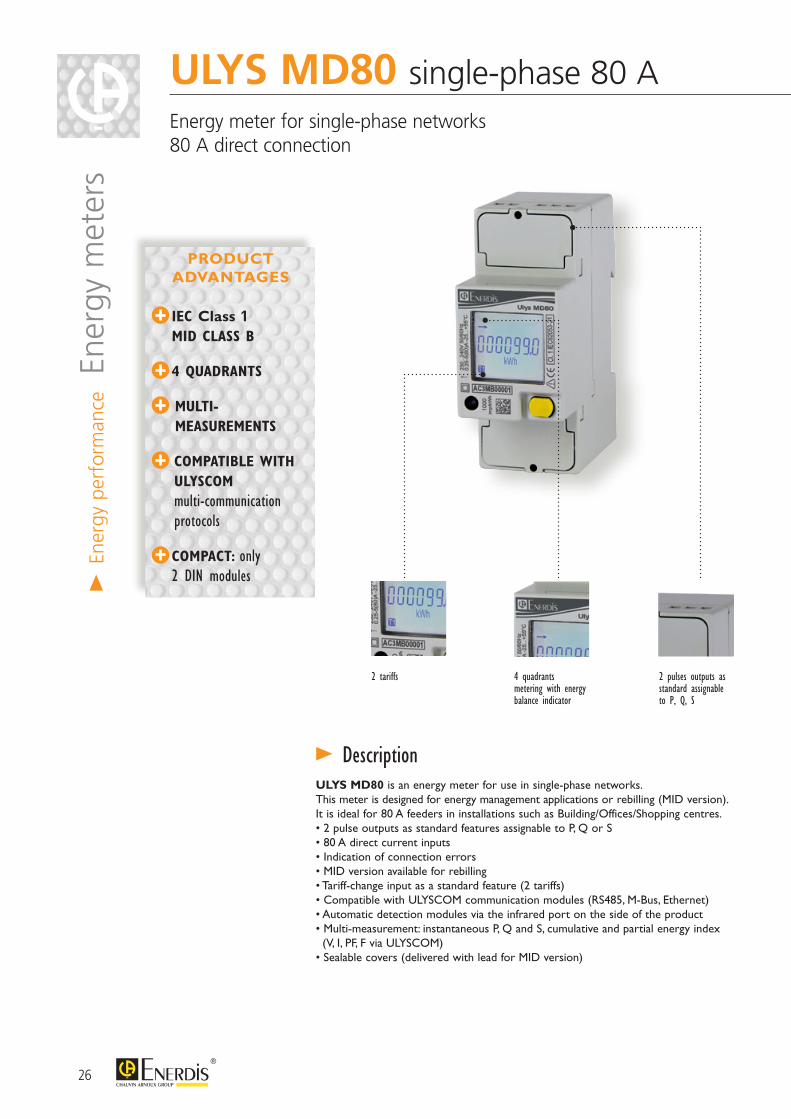
ULYS MD80 single-phase 80 A Energy meter for single-phase networks 80 A direct connection
> En
ergy
per
form
ance E
nerg
y m
eter
s
IEC Class 1 MID CLASS B
4 QUADRANTS
MULTI-MEASUREMENTS
COMPATIBLE WITH ULYSCOM multi-communication protocols
COMPACT: only 2 DIN modules
PRODUCT ADVANTAGES
2 tariffs 4 quadrantsmetering with energy balance indicator
2 pulses outputs as standard assignable to P, Q, S
ULYS MD80 is an energy meter for use in single-phase networks.This meter is designed for energy management applications or rebilling (MID version).It is ideal for 80 A feeders in installations such as Building/Offices/Shopping centres.• 2 pulse outputs as standard features assignable to P, Q or S• 80 A direct current inputs• Indication of connection errors• MID version available for rebilling• Tariff-change input as a standard feature (2 tariffs)• Compatible with ULYSCOM communication modules (RS485, M-Bus, Ethernet)• Automatic detection modules via the infrared port on the side of the product• Multi-measurement: instantaneous P, Q and S, cumulative and partial energy index (V, I, PF, F via ULYSCOM)• Sealable covers (delivered with lead for MID version)
> Description
27
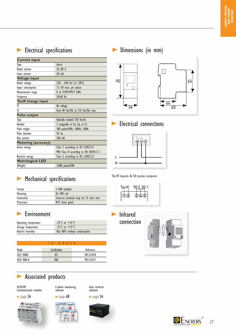
> Electrical specifications
> EnvironmentOperating temperature -25°C to +55°C Storage temperature -25°C to +75°CRelative humidity Max 80% without condensation
> Dimensions (in mm)
> Mechanical specificationsFormat 2 DIN modulesMounting On DIN railConnection Screw-on terminal strip for 35 mm² wireProtection IP51 front panel
Current input Type directRated current (5) 80 A Istart current 20 mAVoltage input Rated voltage 230…240 Vac (± 20%)Input consumption 7.5 VA max. per phaseMeasurement range 0 to 9,999,999.9 kWhFrequency 50/60 HzTariff change inputT1 No voltageT2 from 80 Vac/Vdc to 276 Vac/Vdc max.Pulse outputType Optically isolated 250 Vac/dcNumber 2 assignable to Ea, Eq, or EsPulse weight 500 pulses/kWh, /kVArh, /kVAhPulse duration 50 msMax current 100 mAMetering (accuracy) Active energy Class 1 according to IEC 62053-21 MID Class B according to EN 50470-1-3Reactive energy Class 2 according to IEC 62053-23Metrological LED(Weight) 1,000 pulses/kWh
> Associated productsULYSCOM Communication modules
> page 36
E.online monitoring software
> page 68
> Electrical connections
> Infrared connection
Tariff inputs & S0 pulse outputs
Model Certification ReferenceULYS MD80 IEC P01331010ULYS MD8-M MID P01331011
Data retrieval solutions
> page 56
T O O R D E R
ENER
GY M
ETER
S AN
D PO
WER
M
ONIT
ORS
28
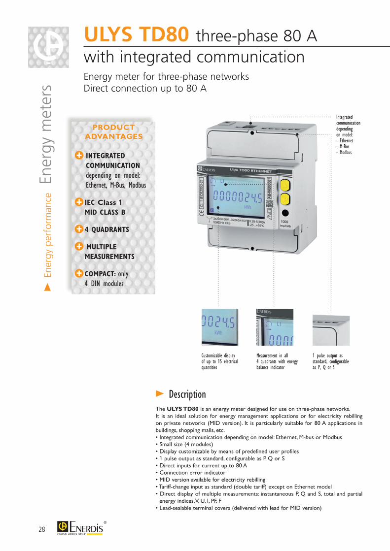
ULYS TD80 three-phase 80 A with integrated communication Energy meter for three-phase networksDirect connection up to 80 A
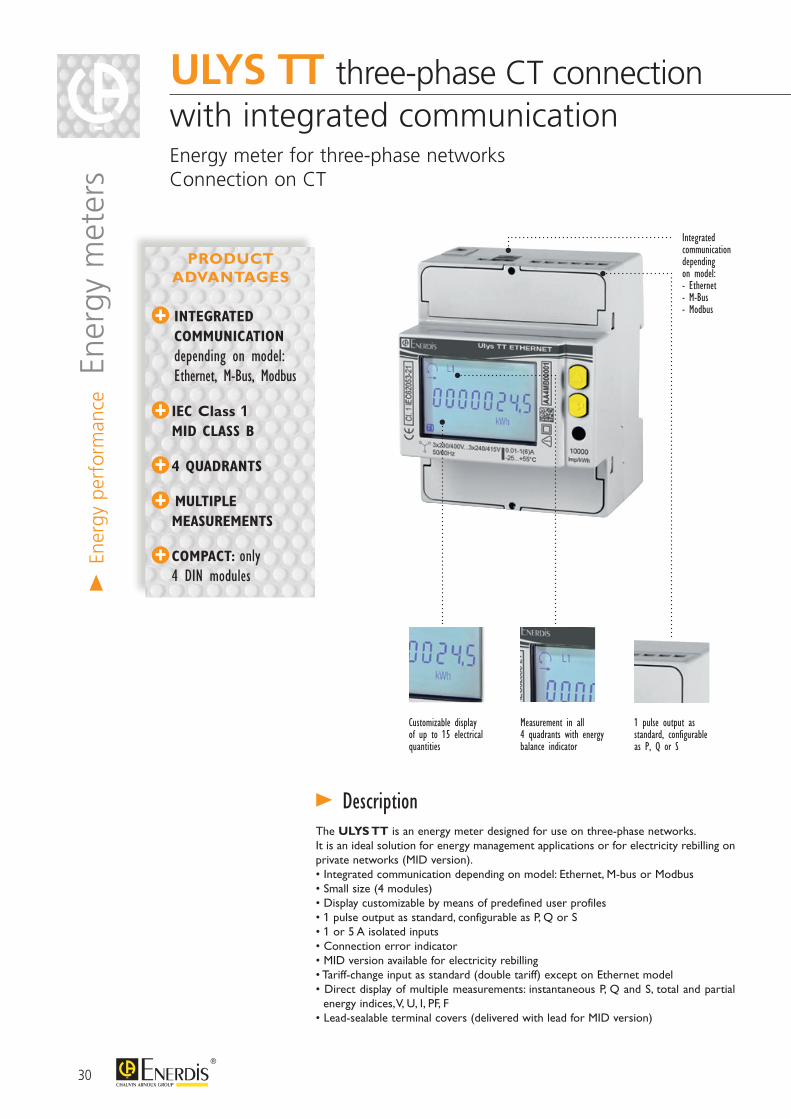
The ULYS TD80 is an energy meter designed for use on three-phase networks.It is an ideal solution for energy management applications or for electricity rebilling on private networks (MID version). It is particularly suitable for 80 A applications in buildings, shopping malls, etc.• Integrated communication depending on model: Ethernet, M-bus or Modbus• Small size (4 modules)• Display customizable by means of predefined user profiles• 1 pulse output as standard, configurable as P, Q or S• Direct inputs for current up to 80 A• Connection error indicator• MID version available for electricity rebilling• Tariff-change input as standard (double tariff) except on Ethernet model• Direct display of multiple measurements: instantaneous P, Q and S, total and partial energy indices, V, U, I, PF, F• Lead-sealable terminal covers (delivered with lead for MID version)
> Description
1 pulse output as standard, configurable as P, Q or S
Integratedcommunicationdependingon model: - Ethernet- M-Bus- Modbus
Customizable display of up to 15 electrical quantities
Measurement in all 4 quadrants with energy balance indicator
INTEGRATED COMMUNICATION depending on model: Ethernet, M-Bus, Modbus
IEC Class 1 MID CLASS B
4 QUADRANTS
MULTIPLE MEASUREMENTS
COMPACT: only 4 DIN modules
PRODUCT ADVANTAGES
> En
ergy
per
form
ance E
nerg
y m
eter
s
29
> Electrical specifications
> EnvironmentOperating temperature -25°C to +55°C Storage temperature -25°C to +75°CRelative humidity Max 80% without condensation
> Dimensions (in mm)
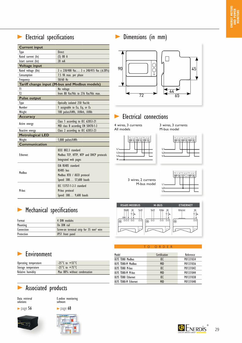
> Mechanical specificationsFormat 4 DIN modulesMounting On DIN railConnection Screw-on terminal strip for 35 mm² wireProtection IP51 front panel
Model Certification ReferenceULYS TD80 Modbus IEC P01331034ULYS TD80-M Modbus MID P01331036ULYS TD80 M-bus IEC P01331042ULYS TD80-M M-bus MID P01331044ULYS TD80 Ethernet IEC P01331038ULYS TD80-M Ethernet MID P01331040
T O O R D E R
> Electrical connections4 wires, 3 currents All models
3 wires, 2 currents M-bus model
3 wires, 3 currents M-bus model
Current inputType DirectRated current (In) (5) 80 AIstart current (Ist) 20 mAVoltage inputRated voltage (Un) 3 x 230/400 Vac… 3 x 240/415 Vac (±20%)Consumption 7.5 VA max. per phaseFrequency 50/60 Hz Tariff change input (M-bus and Modbus models)T1 No voltageT2 from 80 Vac/Vdc to 276 Vac/Vdc max.Pulse outputType Optically isolated 250 Vac/dcNumber 1 assignable to Ea, Eq, or EsWeight 100 pulses/kWh, /kVArh, /kVAhAccuracy
Active energyClass 1 according to IEC 62053-21MID class B according EN 50470-1-3
Reactive energy Class 2 according to IEC 62053-23Metrological LEDWeight 1,000 pulses/kWhCommunication
EthernetIEEE 802.3 standardModbus TCP, HTTP, NTP and DHCP protocolsIntegrated web pages
Modbus
EIA RS485 standardRS485 busModbus RTU / ASCII protocolSpeed: 300… 57,600 bauds
M-busIEC 13757-1-2-3 standardM-bus protocolSpeed: 300… 9,600 bauds
> Associated productsData retrieval solutions
> page 56
E.online monitoring software
> page 68
ENER
GY M
ETER
S AN
D PO
WER
M
ONIT
ORS
30
The ULYS TT is an energy meter designed for use on three-phase networks.It is an ideal solution for energy management applications or for electricity rebilling on private networks (MID version). • Integrated communication depending on model: Ethernet, M-bus or Modbus• Small size (4 modules)• Display customizable by means of predefined user profiles• 1 pulse output as standard, configurable as P, Q or S• 1 or 5 A isolated inputs• Connection error indicator• MID version available for electricity rebilling• Tariff-change input as standard (double tariff) except on Ethernet model• Direct display of multiple measurements: instantaneous P, Q and S, total and partial energy indices, V, U, I, PF, F• Lead-sealable terminal covers (delivered with lead for MID version)
> Description
1 pulse output as standard, configurable as P, Q or S
Measurement in all 4 quadrants with energy balance indicator
Integratedcommunicationdependingon model: - Ethernet- M-Bus- Modbus
Customizable display of up to 15 electrical quantities
ULYS TT three-phase CT connection with integrated communication Energy meter for three-phase networksConnection on CT
INTEGRATED COMMUNICATION depending on model: Ethernet, M-Bus, Modbus
IEC Class 1 MID CLASS B
4 QUADRANTS
MULTIPLE MEASUREMENTS
COMPACT: only 4 DIN modules
PRODUCT ADVANTAGES
> En
ergy
per
form
ance E
nerg
y m
eter
s
31
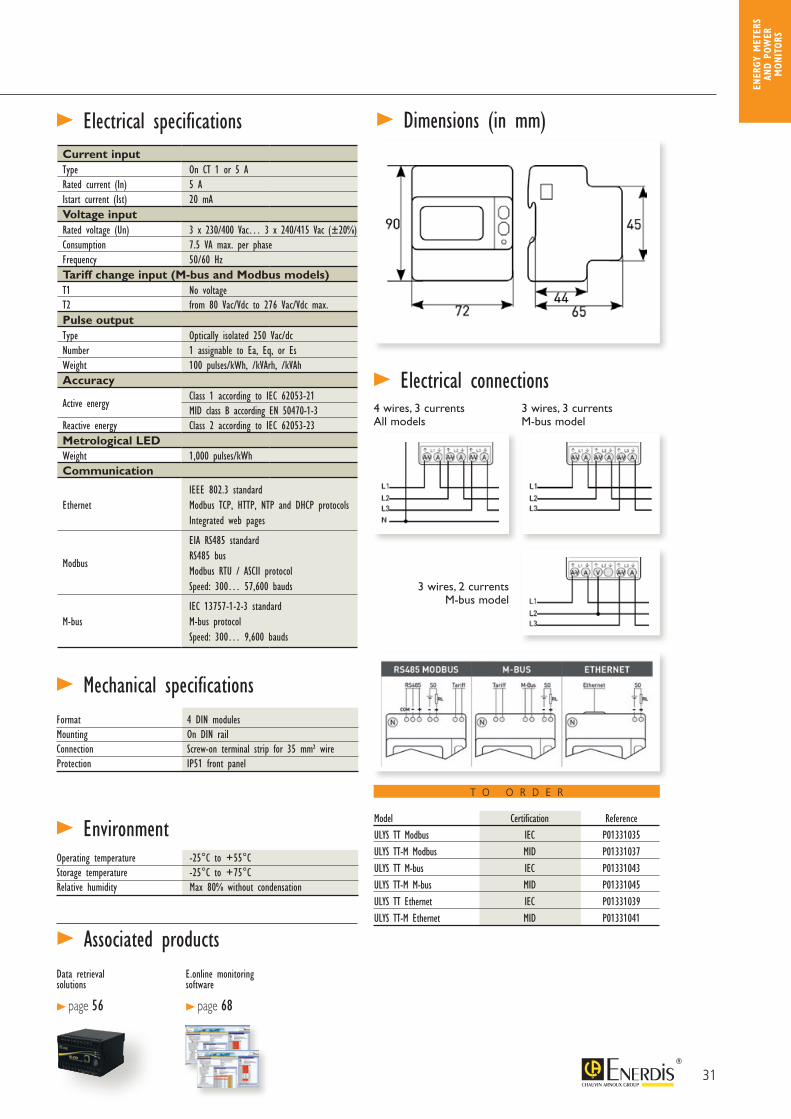
> Electrical specifications
> EnvironmentOperating temperature -25°C to +55°C Storage temperature -25°C to +75°CRelative humidity Max 80% without condensation
> Dimensions (in mm)
> Mechanical specificationsFormat 4 DIN modulesMounting On DIN railConnection Screw-on terminal strip for 35 mm² wireProtection IP51 front panel
> Electrical connections4 wires, 3 currents All models
3 wires, 2 currents M-bus model
3 wires, 3 currents M-bus model
Current inputType On CT 1 or 5 ARated current (In) 5 AIstart current (Ist) 20 mAVoltage inputRated voltage (Un) 3 x 230/400 Vac… 3 x 240/415 Vac (±20%)Consumption 7.5 VA max. per phaseFrequency 50/60 Hz Tariff change input (M-bus and Modbus models)T1 No voltageT2 from 80 Vac/Vdc to 276 Vac/Vdc max.Pulse outputType Optically isolated 250 Vac/dcNumber 1 assignable to Ea, Eq, or EsWeight 100 pulses/kWh, /kVArh, /kVAhAccuracy
Active energyClass 1 according to IEC 62053-21MID class B according EN 50470-1-3
Reactive energy Class 2 according to IEC 62053-23Metrological LEDWeight 1,000 pulses/kWhCommunication
EthernetIEEE 802.3 standardModbus TCP, HTTP, NTP and DHCP protocolsIntegrated web pages
Modbus
EIA RS485 standardRS485 busModbus RTU / ASCII protocolSpeed: 300… 57,600 bauds
M-busIEC 13757-1-2-3 standardM-bus protocolSpeed: 300… 9,600 bauds
> Associated productsData retrieval solutions
> page 56
E.online monitoring software
> page 68
Model Certification ReferenceULYS TT Modbus IEC P01331035ULYS TT-M Modbus MID P01331037ULYS TT M-bus IEC P01331043ULYS TT-M M-bus MID P01331045ULYS TT Ethernet IEC P01331039ULYS TT-M Ethernet MID P01331041
T O O R D E R
ENER
GY M
ETER
S AN
D PO
WER
M
ONIT
ORS
32
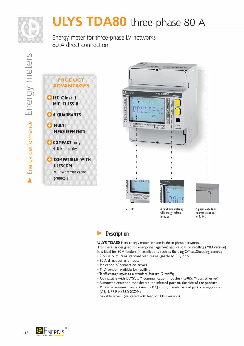
ULYS TDA80 three-phase 80 A Energy meter for three-phase LV networks80 A direct connection
> En
ergy
per
form
ance E
nerg
y m
eter
s
ULYS TDA80 is an energy meter for use in three-phase networks.This meter is designed for energy management applications or rebilling (MID version).It is ideal for 80 A feeders in installations such as Building/Offices/Shopping centres• 2 pulse outputs as standard features assignable to P, Q or S• 80 A direct current inputs• Indication of connection errors• MID version available for rebilling• Tariff-change input as a standard feature (2 tariffs)• Compatible with ULYSCOM communication modules (RS485, M-bus, Ethernet)• Automatic detection modules via the infrared port on the side of the product• Multi-measurement: instantaneous P, Q and S, cumulative and partial energy index (V, U, I, PF, F via ULYSCOM)• Sealable covers (delivered with lead for MID version)
> Description
IEC Class 1 MID CLASS B
4 QUADRANTS
MULTI-MEASUREMENTS
COMPACT: only 4 DIN modules
COMPATIBLE WITH ULYSCOM multi-communication protocols
PRODUCT ADVANTAGES
2 pulses outputs as standard assignable to P, Q, S
2 tariffs 4 quadrants metering with energy balance indicator
33
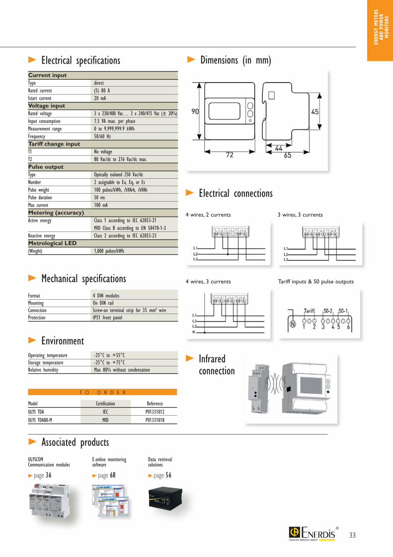
> Electrical specifications
> EnvironmentOperating temperature -25°C to +55°C Storage temperature -25°C to +75°CRelative humidity Max 80% without condensation
> Dimensions (in mm)
> Mechanical specificationsFormat 4 DIN modulesMounting On DIN railConnection Screw-on terminal strip for 35 mm² wireProtection IP51 front panel
> Associated productsULYSCOM Communication modules
> page 36
E.online monitoring software
> page 68
> Electrical connections
> Infrared connection
4 wires, 2 currents
4 wires, 3 currents
3 wires, 3 currents
Tariff inputs & S0 pulse outputs
Model Certification ReferenceULYS TDA IEC P01331012ULYS TDA80-M MID P01331018
Current input Type directRated current (5) 80 A Istart current 20 mAVoltage input Rated voltage 3 x 230/400 Vac… 3 x 240/415 Vac (± 20%)Input consumption 7.5 VA max. per phaseMeasurement range 0 to 9,999,999.9 kWhFrequency 50/60 HzTariff change inputT1 No voltageT2 80 Vac/dc to 276 Vac/dc max.Pulse outputType Optically isolated 250 Vac/dcNumber 2 assignable to Ea, Eq, or EsPulse weight 100 pulses/kWh, /kVArh, /kVAhPulse duration 50 msMax current 100 mAMetering (accuracy) Active energy Class 1 according to IEC 62053-21 MID Class B according to EN 50470-1-3Reactive energy Class 2 according to IEC 62053-23Metrological LED(Weight) 1,000 pulses/kWh
Data retrieval solutions
> page 56
T O O R D E R
ENER
GY M
ETER
S AN
D PO
WER
M
ONIT
ORS
34
ULYS TTA three-phase CT connection Energy meter for three-phase LV networks CT connection
> En
ergy
per
form
ance E
nerg
y m
eter
s
ULYS TTA is an energy meter for use in three-phase networks.This meter is designed for energy management applications or rebilling (MID version).• 2 pulse outputs as standard features assignable to P, Q or S• 1 or 5 A isolated inputs• Indication of connection errors• MID version available for rebilling• Tariff-change input as a standard feature (2 tariffs)• Compatible with ULYSCOM communication modules (RS485, M-bus, Ethernet)• Automatic detection modules via the infrared port on the side of the product• Multi-measurement: instantaneous P, Q and S, cumulative and partial energy index (V, U, I, PF, F via ULYSCOM)• Sealable covers (delivered with lead for MID version)
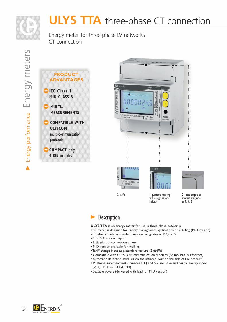
> Description
IEC Class 1 MID CLASS B
MULTI-MEASUREMENTS
COMPATIBLE WITH ULYSCOM multi-communication protocols
COMPACT: only 4 DIN modules
PRODUCT ADVANTAGES
2 pulses outputs as standard assignable to P, Q, S
2 tariffs 4 quadrants meteringwith energy balance indicator
35
Data retrieval solutions
> page 56
T O O R D E R
ENER
GY M
ETER
S AN
D PO
WER
M
ONIT
ORS
> Electrical specifications
> EnvironmentOperating temperature -25°C to +55°C Storage temperature -25°C to +75°CRelative humidity Max 80% without condensation
> Dimensions (in mm)
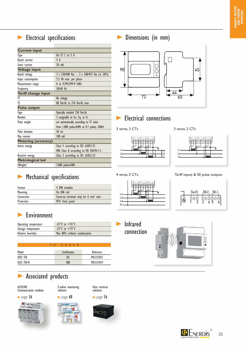
> Mechanical specificationsFormat 4 DIN modulesMounting On DIN railConnection Screw-on terminal strip for 6 mm² wireProtection IP51 front panel
Current input Type On CT 1 or 5 ARated current 5 A Istart current 20 mAVoltage input Rated voltage 3 x 230/400 Vac… 3 x 240/415 Vac (± 20%)Input consumption 7.5 VA max. per phaseMeasurement range 0 to 9,999,999.9 kWhFrequency 50/60 HzTariff change inputT1 No voltageT2 80 Vac/dc to 276 Vac/dc max.Pulse outputType Optically isolated 250 Vac/dcNumber 2 assignable to Ea, Eq, or EsPulse weight set automatically according to CT ratio: from 1,000 pulses/kWh to 0.1 pulses, kVArhPulse duration 50 msMax current 100 mAMetering (accuracy) Active energy Class 1 according to IEC 62053-21 MID Class B according to EN 50470-1-3Reactive energy Class 2 according to IEC 62053-23Metrological led(Weight) 1,000 pulses/kWh
> Associated productsULYSCOM Communication modules
> page 36
E.online monitoring software
> page 68
> Electrical connections3 wires, 3 CTs
4 wires, 3 CTs
3 wires, 2 CTs
Tariff inputs & S0 pulse outputs
> Infrared connection
Model Certification ReferenceULYS TTA IEC P01331015ULYS TTA-M MID P01331019
36
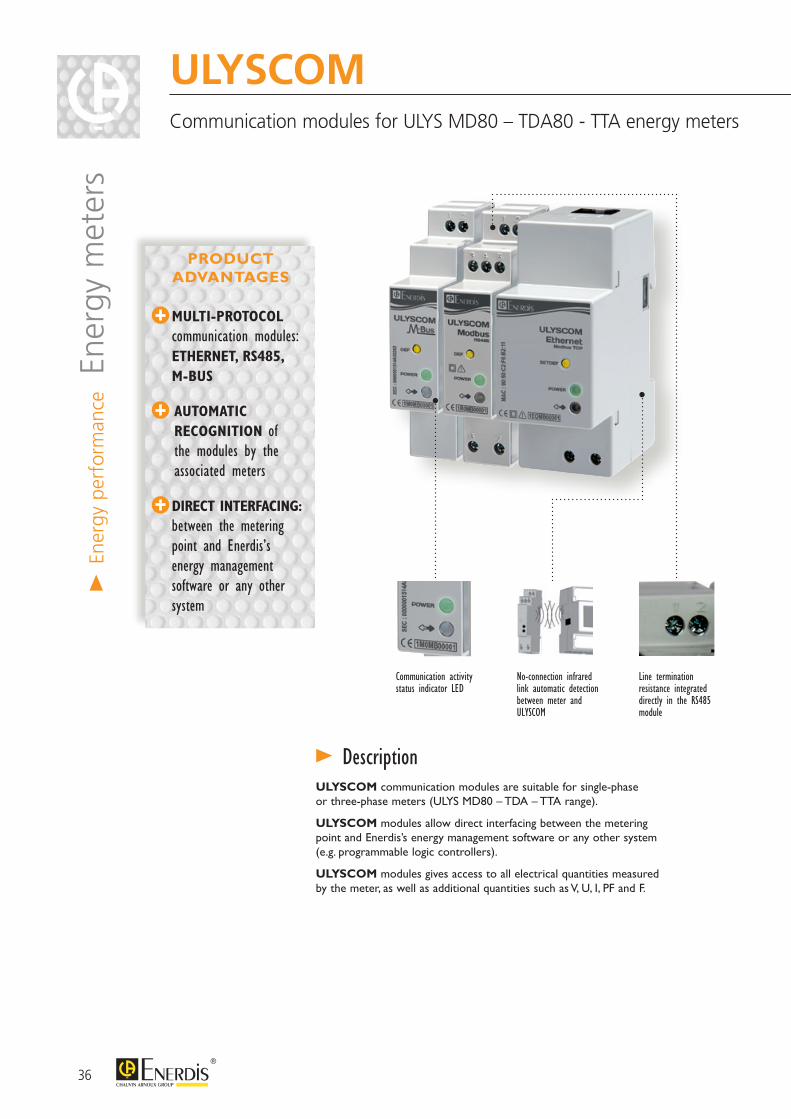
ULYSCOMCommunication modules for ULYS MD80 – TDA80 - TTA energy meters
> En
ergy
per
form
ance E
nerg
y m
eter
s
MULTI-PROTOCOL communication modules: ETHERNET, RS485, M-BUS
AUTOMATIC RECOGNITION of the modules by the associated meters
DIRECT INTERFACING: between the metering point and Enerdis’s energy management software or any other system
PRODUCT ADVANTAGES
Line terminationresistance integrated directly in the RS485 module
ULYSCOM communication modules are suitable for single-phaseor three-phase meters (ULYS MD80 – TDA – TTA range).
ULYSCOM modules allow direct interfacing between the meteringpoint and Enerdis’s energy management software or any other system(e.g. programmable logic controllers).
ULYSCOM modules gives access to all electrical quantities measuredby the meter, as well as additional quantities such as V, U, I, PF and F.
> Description
Communication activity status indicator LED
No-connection infrared link automatic detection between meter and ULYSCOM
37
ENER
GY M
ETER
S AN
D PO
WER
M
ONIT
ORS
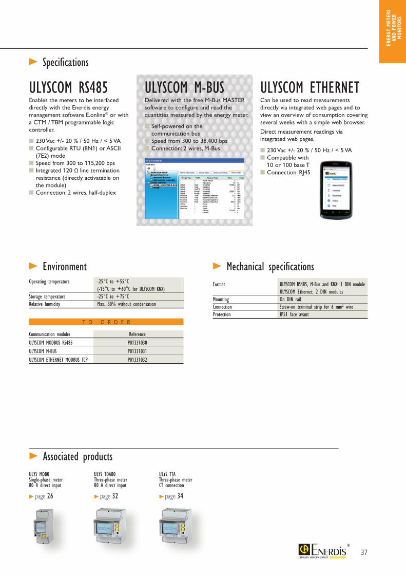
ULYSCOM RS485 Enables the meters to be interfaced directly with the Enerdis energy management software E.online® or with a CTM / TBM programmable logic controller.
230 Vac +/- 20 % / 50 Hz / < 5 VA Configurable RTU (8N1) or ASCII (7E2) mode Speed from 300 to 115,200 bps Integrated 120 Ω line termination resistance (directly activatable on the module) Connection: 2 wires, half-duplex
ULYSCOM M-BUSDelivered with the free M-Bus MASTER software to configure and read the quantities measured by the energy meter.
Self-powered on the communication bus Speed from 300 to 38,400 bps Connection: 2 wires, M-Bus
ULYSCOM ETHERNETCan be used to read measurements directly via integrated web pages and to view an overview of consumption covering several weeks with a simple web browser.
Direct measurement readings viaintegrated web pages.
230 Vac +/- 20 % / 50 Hz / < 5 VA Compatible with 10 or 100 base T Connection: RJ45
> Specifications
> Associated productsULYS MD80 Single-phase meter80 A direct input
> page 26
ULYS TDA80 Three-phase meter80 A direct input
> page 32
ULYS TTA Three-phase meterCT connection
> page 34
> EnvironmentOperating temperature -25°C to +55°C (-15°C to +60°C for ULYSCOM KNX)Storage temperature -25°C to +75°CRelative humidity Max. 80% without condensation
Communication modules ReferenceULYSCOM MODBUS RS485 P01331030ULYSCOM M-BUS P01331031ULYSCOM ETHERNET MODBUS TCP P01331032
> Mechanical specificationsFormat ULYSCOM RS485, M-Bus and KNX: 1 DIN module ULYSCOM Ethernet: 2 DIN modulesMounting On DIN railConnection Screw-on terminal strip for 6 mm² wireProtection IP51 face avant
T O O R D E R

38
Optical head for:- programming- reading the data- upgrading the firmware
Screenless version for DIN-rail mounting or plate mounting
Up to 8 on-off or analogue inputs/outputs
Ethernet output (Modbus/TCP) RS485 output (Modbus/Jbus RTU)
8 LOAD CURVES
16 PROGRAMMABLE ALARMS
GRAPHICS FOR easier data analysis
SPECTRAL ANALYSIS per phase up to the 50th order on U, I and In
QUALIMETRY according to EN50160 STANDARD
PRODUCT ADVANTAGES
A complete range of 6 power monitors ideal for: • LV/MV/HV network supervision• installation sizing
• energy management• electrical network quality applications
Display Real-time display of instantaneous, average…Time/date-stamped recording of min and max values
16 alarms Programmable, viewing of alarms log, recording of the last 64 events
Recording Indices and consumption curves (electricity, water, gas). Temperature curves and trend curves
Customizable screens 3 screens with 4 display lines each to organize the information as you wish
Qualimetry Measurement of THD per phase on U, I and In.Spectral analysis per phase up to the 50th order on U, I and In
Quick programming Current transformer ratios and communication parameters can be set on the front panel or remotely
Graphics For easier data analysis. Fresnel diagram. Gauge for V, U, I, P
Indication of connection errors
Qualimetry Log of the last 1024 events (dips, outages, overvoltages, overcurrents). Waveform capture (V-U-I-In)Statistical analysis graphs as per EN50160
Preventive maintenance Installation operating time. Operating time of monitored equipment
> Description
> Screen displays
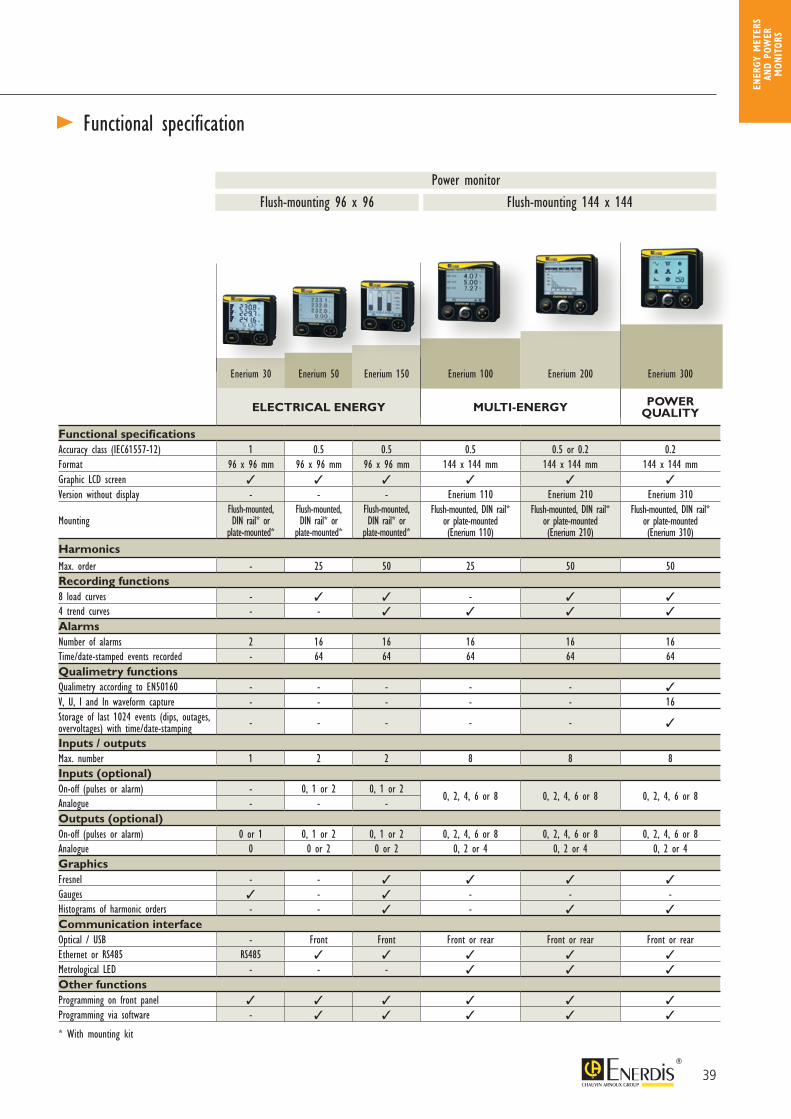
ENERIUM RangePower monitors for all electrical networks compliant with the IEC 61557-12 standard
> En
ergy
per
form
ance P
ower
mon
itors
39
ENER
GY M
ETER
S AN
D PO
WER
M
ONIT
ORS
Flush-mounting 96 x 96 Flush-mounting 144 x 144Power monitor
> Functional specification
Enerium 30 Enerium 50 Enerium 150 Enerium 100 Enerium 200 Enerium 300
ELECTRICAL ENERGY MULTI-ENERGY POWER QUALITY
Functional specificationsAccuracy class (IEC61557-12) 1 0.5 0.5 0.5 0.5 or 0.2 0.2Format 96 x 96 mm 96 x 96 mm 96 x 96 mm 144 x 144 mm 144 x 144 mm 144 x 144 mmGraphic LCD screen
Version without display - - - Enerium 110 Enerium 210 Enerium 310
MountingFlush-mounted,DIN rail* or
plate-mounted*
Flush-mounted,DIN rail* or
plate-mounted*
Flush-mounted,DIN rail* or
plate-mounted*
Flush-mounted, DIN rail* or plate-mounted (Enerium 110)
Flush-mounted, DIN rail* or plate-mounted (Enerium 210)
Flush-mounted, DIN rail* or plate-mounted (Enerium 310)
HarmonicsMax. order - 25 50 25 50 50Recording functions8 load curves - - 4 trend curves - -
AlarmsNumber of alarms 2 16 16 16 16 16Time/date-stamped events recorded - 64 64 64 64 64Qualimetry functionsQualimetry according to EN50160 - - - - -
V, U, I and In waveform capture - - - - - 16Storage of last 1024 events (dips, outages, overvoltages) with time/date-stamping - - - - -
Inputs / outputsMax. number 1 2 2 8 8 8Inputs (optional)On-off (pulses or alarm) - 0, 1 or 2 0, 1 or 2
0, 2, 4, 6 or 8 0, 2, 4, 6 or 8 0, 2, 4, 6 or 8Analogue - - -Outputs (optional)On-off (pulses or alarm) 0 or 1 0, 1 or 2 0, 1 or 2 0, 2, 4, 6 or 8 0, 2, 4, 6 or 8 0, 2, 4, 6 or 8Analogue 0 0 or 2 0 or 2 0, 2 or 4 0, 2 or 4 0, 2 or 4GraphicsFresnel - -
Gauges - - - -Histograms of harmonic orders - - -
Communication interfaceOptical / USB - Front Front Front or rear Front or rear Front or rearEthernet or RS485 RS485
Metrological LED - - -
Other functionsProgramming on front panel
Programming via software -
* With mounting kit
40
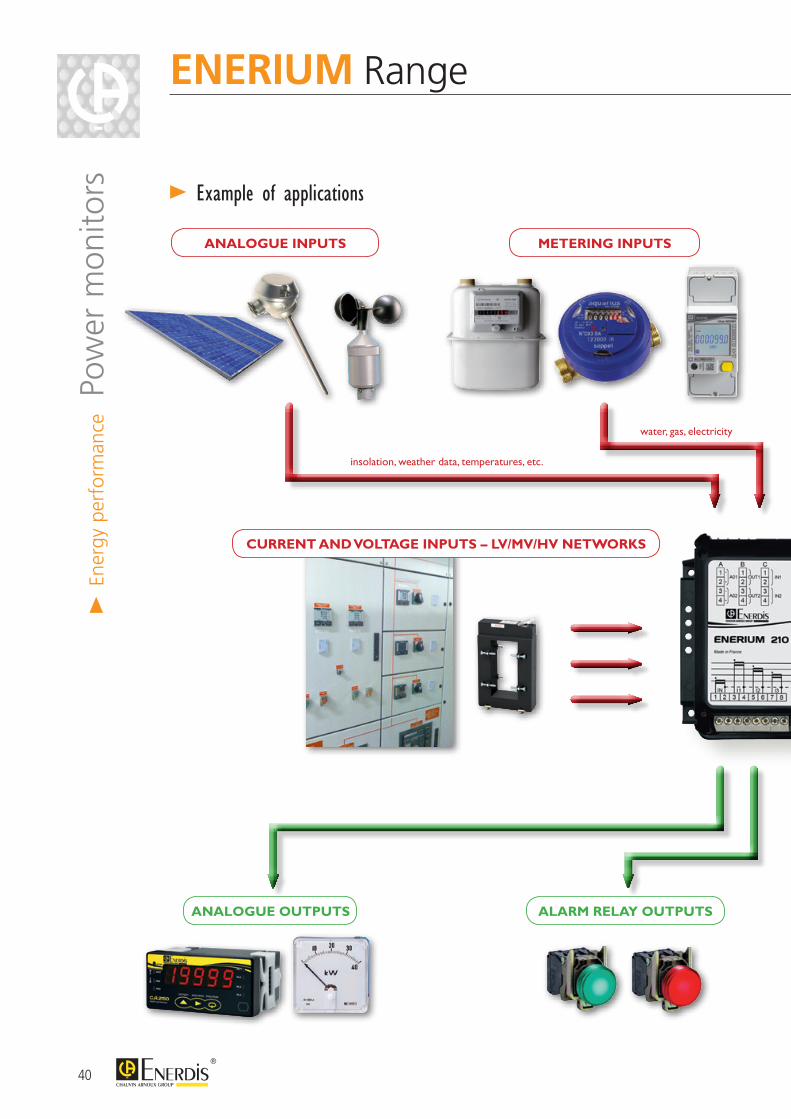
> Example of applications
insolation, weather data, temperatures, etc.
water, gas, electricity
ANALOGUE INPUTS
CURRENT AND VOLTAGE INPUTS – LV/MV/HV NETWORKS
ANALOGUE OUTPUTS ALARM RELAY OUTPUTS
METERING INPUTS
ENERIUM Range>
Ener
gy p
erfo
rman
ce P
ower
mon
itors
41
ENER
GY M
ETER
S AN
D PO
WER
M
ONIT
ORS
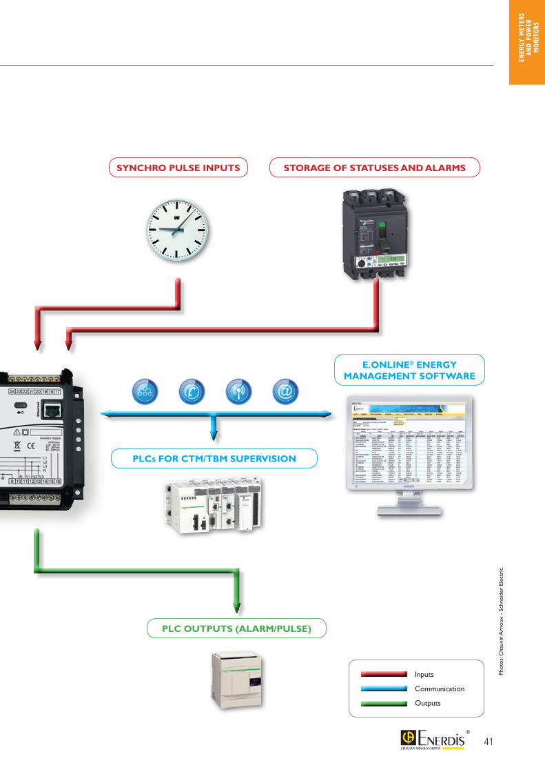
Inputs
Communication
Outputs
Phot
os: C
hauv
in A
rnou
x -
Schn
eide
r El
ectr
ic.
PLCs FOR CTM/TBM SUPERVISION
E.ONLINE® ENERGY MANAGEMENT SOFTWARE
PLC OUTPUTS (ALARM/PULSE)
SYNCHRO PULSE INPUTS STORAGE OF STATUSES AND ALARMS
42
> Measurements 1 S min max average min average max average
V, U
VearthI
In (calculated or measured)(1)
P (4 quadrants)
Pt (4 quadrants)
Q (4 quadrants)
Qt (4 quadrants)
S
St
FP (4 quadrants)
FPt (4 quadrants)
Cosϕ (4 quadrants)Cosϕt (4 quadrants)Tanϕt (4 quadrants)
Frequency
V crest factorI crest factorU unbalanceHarmonics on V, U, IHarmonics on InTHD V, U, I
THD In
Active energy (receiver, generator)
Reactive energy (Qcad1, 2, 3, 4)
Apparent energy (receiver, generator)
On-off input (pulse mode)Analogue input (Enerium 100/200)Voltage presence hour meter (U)Load hour meter (I)
Auxiliary power supply hour meter
Except on Enerium 30(1) on Enerium 30/50/150, calculated only
> Connection diagrams
PhN
Single-phase Balanced 3-phase, 4 wires - 1 CTEnerium 30 only
Balanced 3-phase, 4 wires - 1 CTExcept on Enerium 30
Balanced 3-phase, 3 wires - 1 CTEnerium 30 only
IN+ IN- I1+ I1- I2+ I2- I3+ I3- VT N V1 V2 V3
1R
2S
3T
NN
Aux Aux
Example of connection to VTUnbalanced 3-phase, 3 wires - 2 CTs
Unbalanced 3-phase, 3 wires - 3 CTs
Unbalanced 3-phase, 4 wires - 3 CTs
Unbalanced 3-phase, 4 wires - 4 CTsExcept on Enerium 30/50/150
> En
ergy
per
form
ance P
ower
mon
itors
ENER
GY M
ETER
S AN
D PO
WER
M
ONIT
ORS
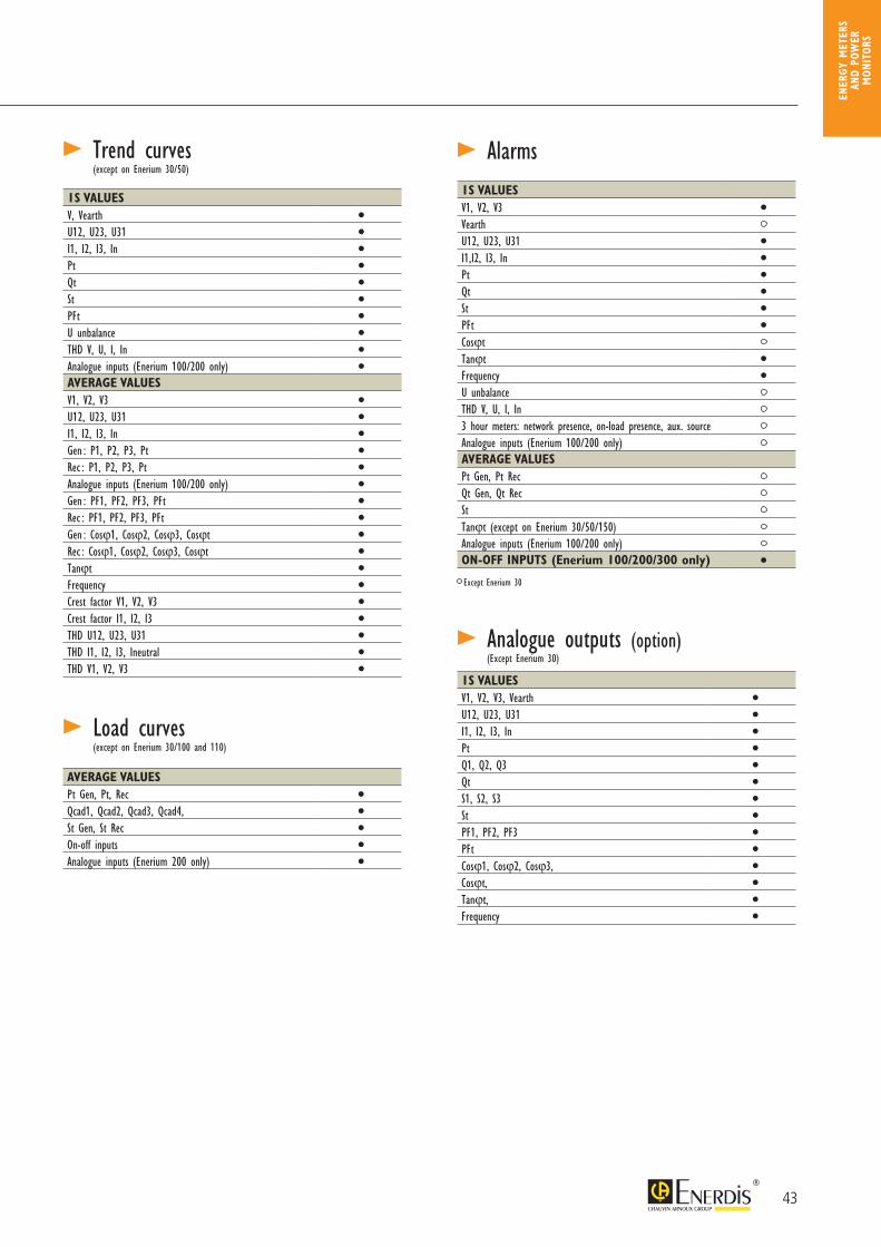
> Alarms
> Analogue outputs (option)
> Trend curves(except on Enerium 30/50)
1S VALUESV, Vearth
U12, U23, U31
I1, I2, I3, In
Pt
Qt
St
PFt
U unbalance
THD V, U, I, In
Analogue inputs (Enerium 100/200 only)
AVERAGE VALUESV1, V2, V3
U12, U23, U31
I1, I2, I3, In
Gen : P1, P2, P3, Pt
Rec : P1, P2, P3, Pt
Analogue inputs (Enerium 100/200 only)
Gen : PF1, PF2, PF3, PFt
Rec : PF1, PF2, PF3, PFt
Gen : Cosϕ1, Cosϕ2, Cosϕ3, Cosϕt
Rec : Cosϕ1, Cosϕ2, Cosϕ3, Cosϕt
Tanϕt
Frequency
Crest factor V1, V2, V3
Crest factor I1, I2, I3
THD U12, U23, U31
THD I1, I2, I3, Ineutral
THD V1, V2, V3
1S VALUESV1, V2, V3
VearthU12, U23, U31
I1,I2, I3, In
Pt
Qt
St
PFt
CosϕtTanϕt
Frequency
U unbalanceTHD V, U, I, In3 hour meters: network presence, on-load presence, aux. sourceAnalogue inputs (Enerium 100/200 only)AVERAGE VALUESPt Gen, Pt RecQt Gen, Qt Rec StTanϕt (except on Enerium 30/50/150)Analogue inputs (Enerium 100/200 only)ON-OFF INPUTS (Enerium 100/200/300 only)
1S VALUESV1, V2, V3, Vearth
U12, U23, U31
I1, I2, I3, In
Pt
Q1, Q2, Q3
Qt
S1, S2, S3
St
PF1, PF2, PF3
PFt
Cosϕ1, Cosϕ2, Cosϕ3,
Cosϕt,
Tanϕt,
Frequency
(except on Enerium 30/100 and 110) > Load curves
AVERAGE VALUESPt Gen, Pt, Rec
Qcad1, Qcad2, Qcad3, Qcad4,
St Gen, St Rec
On-off inputs
Analogue inputs (Enerium 200 only)
(Except Enerium 30)
Except Enerium 30
43
44
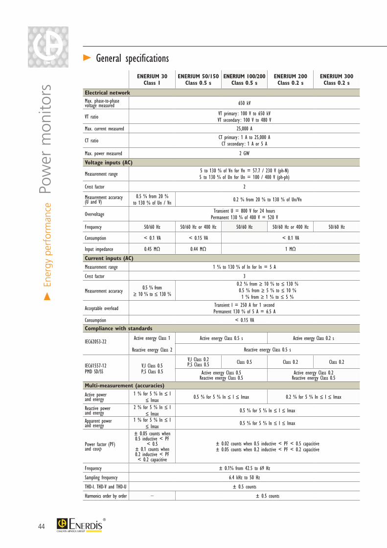
> General specifications
ENERIUM 30Class 1
ENERIUM 50/150Class 0.5 s
ENERIUM 100/200Class 0.5 s
ENERIUM 200Class 0.2 s
ENERIUM 300Class 0.2 s
Electrical networkMax. phase-to-phase voltage measured 650 kV
VT ratio VT primary : 100 V to 650 kV VT secondary : 100 V to 480 V
Max. current measured 25,000 A
CT ratio CT primary : 1 A to 25,000 ACT secondary : 1 A or 5 A
Max. power measured 2 GW
Voltage inputs (AC)
Measurement range 5 to 130 % of Vn for Vn = 57.7 / 230 V (ph-N)5 to 130 % of Un for Un = 100 / 400 V (ph-ph)
Crest factor 2
Measurement accuracy (U and V)
0.5 % from 20 % to 130 % of Un / Vn 0.2 % from 20 % to 130 % of Un/Vn
Overvoltage Transient U = 800 V for 24 hoursPermanent 130 % of 400 V = 520 V
Frequency 50/60 Hz 50/60 Hz or 400 Hz 50/60 Hz 50/60 Hz or 400 Hz 50/60 Hz
Consumption < 0.1 VA < 0.15 VA < 0.1 VA
Input impedance 0.45 MΩ 0.44 MΩ 1 MΩ
Current inputs (AC)Measurement range 1 % to 130 % of In for In = 5 A
Crest factor 3
Measurement accuracy 0.5 % from ≥ 10 % to ≤ 130 %
0.2 % from ≥ 10 % to ≤ 130 % 0.5 % from ≥ 5 % to ≤ 10 % 1 % from ≥ 1 % to ≤ 5 %
Acceptable overload Transient I = 250 A for 1 secondPermanent 130 % of 5 A = 6.5 A
Consumption < 0.15 VA
Compliance with standards
IEC62053-22Active energy Class 1
Reactive energy Class 2
Active energy Class 0.5 s Active energy Class 0.2 s
Reactive energy Class 0.5 s
IEC61557-12 PMD SD/SS
V,I Class 0.5P,S Class 0.5
V,I Class 0.2 P,S Class 0.5 Class 0.5 Class 0.2 Class 0.2
Active energy Class 0.5 Reactive energy Class 0.5
Active energy Class 0.2Reactive energy Class 0.5
Multi-measurement (accuracies)
Active power and energy
1 % for 5 % In ≤ I ≤ Imax 0.5 % for 5 % In ≤ I ≤ Imax 0.2 % for 5 % In ≤ I ≤ Imax
Reactive power and energy
2 % for 5 % In ≤ I ≤ Imax 0.5 % for 5 % In ≤ I ≤ Imax
Apparent power and energy
1 % for 5 % In ≤ I ≤ Imax 0.5 % for 5 % In ≤ I ≤ Imax
Power factor (PF) and cosϕ
± 0.05 counts when 0.5 inductive < PF
< 0.5± 0.1 counts when 0.2 inductive < PF < 0.2 capacitive
± 0.02 counts when 0.5 inductive < PF < 0.5 capacitive ± 0.05 counts when 0.2 inductive < PF < 0.2 capacitive
Frequency ± 0.1% from 42.5 to 69 Hz
Sampling frequency 6.4 kHz to 50 Hz
THD-I. THD-V and THD-U ± 0.5 counts
Harmonics order by order – ± 0.5 counts
> En
ergy
per
form
ance P
ower
mon
itors
45
ENER
GY M
ETER
S AN
D PO
WER
M
ONIT
ORS
ENERIUM 30Class 1
ENERIUM 50/150Class 0.5 s
ENERIUM 100/200Class 0.5 s
ENERIUM 200Class 0.2 s
ENERIUM 300Class 0.2 s
Electrical networkMax. phase-to-phase voltage measured 650 kV
VT ratio VT primary : 100 V to 650 kV VT secondary : 100 V to 480 V
Max. current measured 25,000 A
CT ratio CT primary : 1 A to 25,000 ACT secondary : 1 A or 5 A
Max. power measured 2 GW
Voltage inputs (AC)
Measurement range 5 to 130 % of Vn for Vn = 57.7 / 230 V (ph-N)5 to 130 % of Un for Un = 100 / 400 V (ph-ph)
Crest factor 2
Measurement accuracy (U and V)
0.5 % from 20 % to 130 % of Un / Vn 0.2 % from 20 % to 130 % of Un/Vn
Overvoltage Transient U = 800 V for 24 hoursPermanent 130 % of 400 V = 520 V
Frequency 50/60 Hz 50/60 Hz or 400 Hz 50/60 Hz 50/60 Hz or 400 Hz 50/60 Hz
Consumption < 0.1 VA < 0.15 VA < 0.1 VA
Input impedance 0.45 MΩ 0.44 MΩ 1 MΩ
Current inputs (AC)Measurement range 1 % to 130 % of In for In = 5 A
Crest factor 3
Measurement accuracy 0.5 % from ≥ 10 % to ≤ 130 %
0.2 % from ≥ 10 % to ≤ 130 % 0.5 % from ≥ 5 % to ≤ 10 % 1 % from ≥ 1 % to ≤ 5 %
Acceptable overload Transient I = 250 A for 1 secondPermanent 130 % of 5 A = 6.5 A
Consumption < 0.15 VA
Compliance with standards
IEC62053-22Active energy Class 1
Reactive energy Class 2
Active energy Class 0.5 s Active energy Class 0.2 s
Reactive energy Class 0.5 s
IEC61557-12 PMD SD/SS
V,I Class 0.5P,S Class 0.5
V,I Class 0.2 P,S Class 0.5 Class 0.5 Class 0.2 Class 0.2
Active energy Class 0.5 Reactive energy Class 0.5
Active energy Class 0.2Reactive energy Class 0.5
Multi-measurement (accuracies)
Active power and energy
1 % for 5 % In ≤ I ≤ Imax 0.5 % for 5 % In ≤ I ≤ Imax 0.2 % for 5 % In ≤ I ≤ Imax
Reactive power and energy
2 % for 5 % In ≤ I ≤ Imax 0.5 % for 5 % In ≤ I ≤ Imax
Apparent power and energy
1 % for 5 % In ≤ I ≤ Imax 0.5 % for 5 % In ≤ I ≤ Imax
Power factor (PF) and cosϕ
± 0.05 counts when 0.5 inductive < PF
< 0.5± 0.1 counts when 0.2 inductive < PF < 0.2 capacitive
± 0.02 counts when 0.5 inductive < PF < 0.5 capacitive ± 0.05 counts when 0.2 inductive < PF < 0.2 capacitive
Frequency ± 0.1% from 42.5 to 69 Hz
Sampling frequency 6.4 kHz to 50 Hz
THD-I. THD-V and THD-U ± 0.5 counts
Harmonics order by order – ± 0.5 counts
ENERIUM 30Class 1
ENERIUM 50/150Class 0.5 s
ENERIUM 100/200Class 0.5 s
ENERIUM 200Class 0.2 s
ENERIUM 300Class 0.2 s
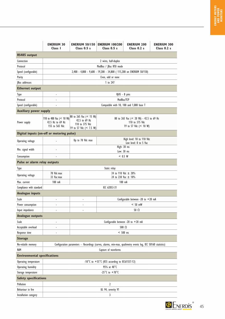
RS485 output
Connection 2 wires, half-duplex
Protocol ModBus / JBus RTU mode
Speed (configurable) 2,400 - 4,800 - 9,600 - 19,200 - 34,800 ( 115,200 on ENERIUM 50/150)
Parity Even, odd or none
JBus addresses 1 to 247
Ethernet output
Type - RJ45 - 8 pins
Protocol - ModBus/TCP
Speed (configurable) - Compatible with 10, 100 and 1,000 base T
Auxiliary power supply
Power supply 110 to 400 Vac (< 10 VA)
42.5 Hz to 69 Hz155 to 565 Vdc
80 to 265 Vac (< 15 VA) 42.5 to 69 Hz110 to 375 Vdc
19 to 57 Vdc (< 7.5 W)
80 to 265 Vac (< 20 VA) - 42.5 to 69 Hz110 to 375 Vdc
19 to 57 Vdc (< 10 W)
Digital inputs (on-off or metering pulse)
Operating voltage - Up to 70 Vdc max High level: 10 to 110 Vdc Low level: 0 to 5 Vac
Min. signal width -High: 30 msLow: 30 ms
Consumption - < 0.5 W
Pulse or alarm relay outputs
Type Static relay
Operating voltage 70 Vdc max33 Vac max
24 to 110 Vdc ± 20%24 to 230 Vac ± 10%
Max. current 100 mA 100 mA
Compliance with standard IEC 62053-31
Analogue inputs
Scale - - Configurable between -20 to +20 mA
Power consumption - - < 50 mW
Input impedance - - 50 Ω
Analogue outputs
Scale - Configurable between -20 to +20 mA
Acceptable overload - 500 Ω
Response time - < 500 ms
Storage
No-volatile memory Configuration parameters – Recordings (curves, alarms, min-max, qualimetry events log, IEC 50160 statistics)
RAM Capture of waveforms
Environmental specifications
Operating temperature -10°C to +55°C (K55 according to IEC61557-12)
Operating humidity 95% at 40°C
Storage temperature -25°C to +70°C
Safety specifications
Pollution 2
Behaviour in fire UL 94, severity V1
Installation category 3
46
E.set P01330501E.View P01330601E.View+ P01330610
> SoftwareOptical head for ENERIUM 50/150 P01330403Optical head for ENERIUM 100/110 - 200/210 – 300/310 P01330401DIN-rail mounting kit for ENERIUM 30/50/150 P01330830DIN-rail mounting kit for ENERIUM 100/200/300 P01330360690 V / 400 V resistive voltage adapter (for wind-turbine applications) P01330402
Power supply for On-Off inputs 85 to 256 Vac/12 Vdc – 3.5 A (42 W) ACCJ1004
> Accessories
> En
ergy
per
form
ance P
ower
mon
itors
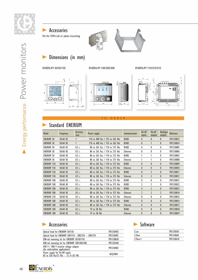
> Dimensions (in mm)
ENERIUM 100/200/300 ENERIUM 110/210/310ENERIUM 30/50/150
> AccessoriesKit for DIN-rail or plate mounting
Model Frequency Accuracy class Power supply Communication On-off
inputsOn-off outputs
Analogue outputs Reference
ENERIUM 30 50/60 HZ 1 110 to 400 Vac / 155 to 565 Vdc RS485 0 0 0 P01330823ENERIUM 30 50/60 HZ 1 110 to 400 Vac / 155 to 565 Vdc RS485 0 1 0 P01330824ENERIUM 50 50/60 HZ 0.5 s 80 to 265 Vac / 110 to 375 Vdc RS485 0 0 0 P01330805ENERIUM 50 50/60 HZ 0.5 s 80 to 265 Vac / 110 to 375 Vdc Ethernet 0 0 0 P01330806ENERIUM 50 50/60 HZ 0.5 s 80 to 265 Vac / 110 to 375 Vdc RS485 1 1 0 P01330807ENERIUM 50 50/60 HZ 0.5 s 80 to 265 Vac / 110 to 375 Vdc Ethernet 1 1 0 P01330808ENERIUM 150 50/60 HZ 0.5 s 80 to 265 Vac / 110 to 375 Vdc RS485 0 0 0 P01330809ENERIUM 150 50/60 HZ 0.5 s 80 to 265 Vac / 110 to 375 Vdc Ethernet 0 0 0 P01330810ENERIUM 150 50/60 HZ 0.5 s 80 to 265 Vac / 110 to 375 Vdc RS485 0 2 0 P01330811ENERIUM 150 50/60 HZ 0.5 s 80 to 265 Vac / 110 to 375 Vdc Ethernet 0 2 0 P01330812ENERIUM 100 50/60 HZ 0.5 s 80 to 265 Vac / 110 to 375 Vdc RS485 0 0 0 P01330831ENERIUM 100 50/60 HZ 0.5 s 80 to 265 Vac / 110 to 375 Vdc RS485 2 2 0 P01330832ENERIUM 200 50/60 HZ 0.5 s 80 to 265 Vac / 110 to 375 Vdc RS485 4 2 0 P01330833ENERIUM 200 50/60 HZ 0.5 s 80 to 265 Vac / 110 to 375 Vdc Ethernet 2 2 2 P01330834ENERIUM 210 50/60 HZ 0.5 s 80 to 265 Vac / 110 to 375 Vdc Ethernet 8 0 0 P01330835ENERIUM 300 50/60 HZ 0.2 s 80 to 265 Vac / 110 to 375 Vdc RS485 0 0 0 P01330816ENERIUM 300 50/60 HZ 0.2 s 80 to 265 Vac / 110 to 375 Vdc Ethernet 0 0 0 P01330817ENERIUM 300 50/60 HZ 0.2 s 19 to 58 Vdc RS485 0 0 0 P01330818ENERIUM 300 50/60 HZ 0.2 s 19 to 58 Vdc Ethernet 0 0 0 P01330819
> Standard ENERIUMT O O R D E R
47
> Associated productsData retrieval solutions
> page 56
E.online monitoring software
> page 68
Currenttransformers
> page 102
ENER
GY M
ETER
S AN
D PO
WER
M
ONIT
ORS
ENERIUM 1 2 3 4 5 6 7 8 9
1 Model 6 On-Off outputs
50 ENERIUM 50 – Electrical energy – Load curves - Format 96 x 96 150 ENERIUM 50 + Trend curves - Format 96 x 96 100 ENERIUM 100 – Multi-energy - Trend curves - Format 144 x 144 110 ENERIUM 100 screenless version - Format 144 x 144200 ENERIUM 100 + Load curves - Format 144 x 144210 ENERIUM 200 screenless version - Format 144 x 144300 ENERIUM 200 + Qualimetry310 ENERIUM 300 screenless version
0 none1 output (only on ENERIUM 50/150)2 2 outputs4 4 outputs (except on ENERIUM 30/50/150)6 6 outputs (except on ENERIUM 30/50/150)8 8 outputs (except on ENERIUM 30/50/150)
7 Analogue inputs (ENERIUM 100/200/300 only)
0 none2 2 analogue inputs4 4 analogue inputs6 6 analogue inputs8 8 analogue inputs
3 Auxiliary power supply
0 80 to 265 Vac / 110 to 375 Vdc1 19.2 to 58 Vdc
4 Communication
0 RS4851 Ethernet
5 Metering (or On-Off) inputs
0 none1 1 input (only on ENERIUM 50/150)2 2 inputs4 4 inputs (except on ENERIUM 50/150)6 6 inputs (except on ENERIUM 50/150)8 8 inputs (except on ENERIUM 50/150)
Note : with choices 5, 6, 7 and 8, it is possible to have a maximum of 8 inputs and/or outputs (ENERIUM 100-110/200-210).Note: for the Enerium 50/150, choices 5 and 6 only allow the following combinations: 0-0, 1-1, 2-0, 0-2.
9 Accuracy class
8 Analogue outputs
0 none2 2 outputs4 4 outputs (except on ENERIUM 50/150)
5 0.5 s (except on ENERIUM 300)2 0.2s (ENERIUM 200/210/300/310 only)
Example : Enerium 200, frequency 50/60 Hz, 80 to 264 Vac auxiliary power supply, RS485 communication, 2 on-off inputs, no on-off outputs, no analogue inputs, no analogue outputs, Class 0.2s=> order ENERIUM 200 01020002 • 1-200 • 2-1 • 3-1 • 4-0 • 5-2 • 6-0 • 7-0 • 8-0 • 9-2
2 Frequency of network measured
0 50/60 Hz1 400 Hz (except on Enerium 100 / 200 class 0.5s / 300)
> Configured products
E.set P01330501E.View P01330601E.View+ P01330610
47
Model Frequency Accuracy class Power supply Communication On-off
inputsOn-off outputs
Analogue outputs Reference
ENERIUM 30 50/60 HZ 1 110 to 400 Vac / 155 to 565 Vdc RS485 0 0 0 P01330823ENERIUM 30 50/60 HZ 1 110 to 400 Vac / 155 to 565 Vdc RS485 0 1 0 P01330824ENERIUM 50 50/60 HZ 0.5 s 80 to 265 Vac / 110 to 375 Vdc RS485 0 0 0 P01330805ENERIUM 50 50/60 HZ 0.5 s 80 to 265 Vac / 110 to 375 Vdc Ethernet 0 0 0 P01330806ENERIUM 50 50/60 HZ 0.5 s 80 to 265 Vac / 110 to 375 Vdc RS485 1 1 0 P01330807ENERIUM 50 50/60 HZ 0.5 s 80 to 265 Vac / 110 to 375 Vdc Ethernet 1 1 0 P01330808ENERIUM 150 50/60 HZ 0.5 s 80 to 265 Vac / 110 to 375 Vdc RS485 0 0 0 P01330809ENERIUM 150 50/60 HZ 0.5 s 80 to 265 Vac / 110 to 375 Vdc Ethernet 0 0 0 P01330810ENERIUM 150 50/60 HZ 0.5 s 80 to 265 Vac / 110 to 375 Vdc RS485 0 2 0 P01330811ENERIUM 150 50/60 HZ 0.5 s 80 to 265 Vac / 110 to 375 Vdc Ethernet 0 2 0 P01330812ENERIUM 100 50/60 HZ 0.5 s 80 to 265 Vac / 110 to 375 Vdc RS485 0 0 0 P01330831ENERIUM 100 50/60 HZ 0.5 s 80 to 265 Vac / 110 to 375 Vdc RS485 2 2 0 P01330832ENERIUM 200 50/60 HZ 0.5 s 80 to 265 Vac / 110 to 375 Vdc RS485 4 2 0 P01330833ENERIUM 200 50/60 HZ 0.5 s 80 to 265 Vac / 110 to 375 Vdc Ethernet 2 2 2 P01330834ENERIUM 210 50/60 HZ 0.5 s 80 to 265 Vac / 110 to 375 Vdc Ethernet 8 0 0 P01330835ENERIUM 300 50/60 HZ 0.2 s 80 to 265 Vac / 110 to 375 Vdc RS485 0 0 0 P01330816ENERIUM 300 50/60 HZ 0.2 s 80 to 265 Vac / 110 to 375 Vdc Ethernet 0 0 0 P01330817ENERIUM 300 50/60 HZ 0.2 s 19 to 58 Vdc RS485 0 0 0 P01330818ENERIUM 300 50/60 HZ 0.2 s 19 to 58 Vdc Ethernet 0 0 0 P01330819
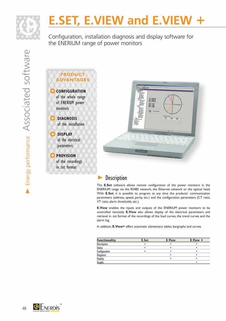
48
The E.Set software allows remote configuration of the power monitors in the ENERIUM range via the RS485 network, the Ethernet network or the optical head. With E.Set, it is possible to program at any time the products’ communication parameters (address, speed, parity, etc.) and the configuration parameters (CT ratio, VT ratio, alarm thresholds, etc.).
E.View enables the inputs and outputs of the ENERIUM power monitors to be controlled remotely. E.View also allows display of the electrical parameters and retrieval in .txt format of the recordings of the load curves, the trend curves and the alarm log.
In addition, E.View+ offers automatic elementary tables, bargraphs and curves.
> Description
Functionality E.Set E.View E.View +Description • • •Status • • •Configuration • • •Diagnosis • •Display • •Graphs •
E.SET, E.VIEW and E.VIEW +
Configuration, installation diagnosis and display software for the ENERIUM range of power monitors
> En
ergy
per
form
ance A
ssoc
iate
d so
ftw
are
CONFIGURATION
of the whole range of ENERIUM power monitors
DIAGNOSIS
of the installation
DISPLAY
of the electrical parameters
PROVISION
of the recordings in .txt format
PRODUCT ADVANTAGES
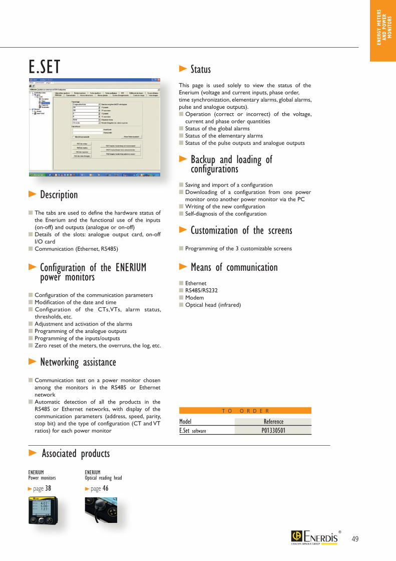
49
T O O R D E R
ENER
GY M
ETER
S AN
D PO
WER
M
ONIT
ORS
Model ReferenceE.Set software P01330501
> Status This page is used solely to view the status of the Enerium (voltage and current inputs, phase order,time synchronization, elementary alarms, global alarms, pulse and analogue outputs). Operation (correct or incorrect) of the voltage,
current and phase order quantities Status of the global alarms Status of the elementary alarms Status of the pulse outputs and analogue outputs
> Backup and loading of configurations
Saving and import of a configuration Downloading of a configuration from one power
monitor onto another power monitor via the PC Writing of the new configuration Self-diagnosis of the configuration
> Customization of the screens Programming of the 3 customizable screens
> Means of communication
Ethernet RS485/RS232 Modem Optical head (infrared)
> Description The tabs are used to define the hardware status of
the Enerium and the functional use of the inputs (on-off) and outputs (analogue or on-off)
Details of the slots: analogue output card, on-off I/O card
Communication (Ethernet, RS485)
> Configuration of the ENERIUM power monitors
Configuration of the communication parameters Modification of the date and time Configuration of the CTs,VTs, alarm status,
thresholds, etc. Adjustment and activation of the alarms Programming of the analogue outputs Programming of the inputs/outputs Zero reset of the meters, the overruns, the log, etc.
> Networking assistance
Communication test on a power monitor chosen among the monitors in the RS485 or Ethernet network
Automatic detection of all the products in the RS485 or Ethernet networks, with display of the communication parameters (address, speed, parity, stop bit) and the type of configuration (CT and VT ratios) for each power monitor
> Associated products
ENERIUMOptical reading head
> page 46
ENERIUMPower monitors
> page 38
E.SET
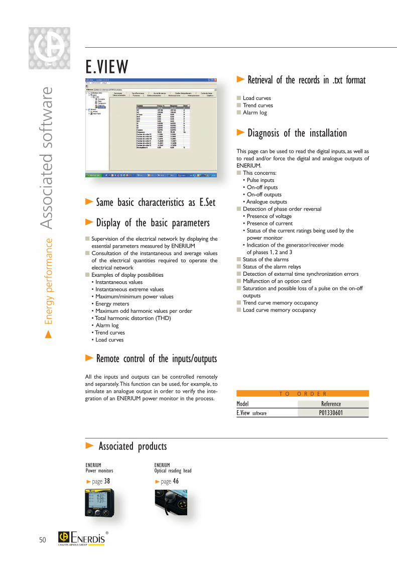
50
T O O R D E R
E.VIEW
> Same basic characteristics as E.Set
> Display of the basic parameters Supervision of the electrical network by displaying the
essential parameters measured by ENERIUM Consultation of the instantaneous and average values
of the electrical quantities required to operate the electrical network
Examples of display possibilities • Instantaneous values • Instantaneous extreme values • Maximum/minimum power values • Energy meters • Maximum odd harmonic values per order • Total harmonic distortion (THD) • Alarm log • Trend curves • Load curves
> Remote control of the inputs/outputsAll the inputs and outputs can be controlled remotely and separately. This function can be used, for example, to simulate an analogue output in order to verify the inte-gration of an ENERIUM power monitor in the process.
> Retrieval of the records in .txt format Load curves Trend curves Alarm log
> Diagnosis of the installationThis page can be used to read the digital inputs, as well as to read and/or force the digital and analogue outputs of ENERIUM. This concerns:
• Pulse inputs • On-off inputs • On-off outputs • Analogue outputs
Detection of phase order reversal • Presence of voltage • Presence of current • Status of the current ratings being used by the
power monitor• Indication of the generator/receiver mode
of phases 1, 2 and 3 Status of the alarms Status of the alarm relays Detection of external time synchronization errors Malfunction of an option card Saturation and possible loss of a pulse on the on-off
outputs Trend curve memory occupancy Load curve memory occupancy
Model ReferenceE.View software P01330601
> Associated products
> En
ergy
per
form
ance A
ssoc
iate
d so
ftw
are
ENERIUMOptical reading head
> page 46
ENERIUMPower monitors
> page 38
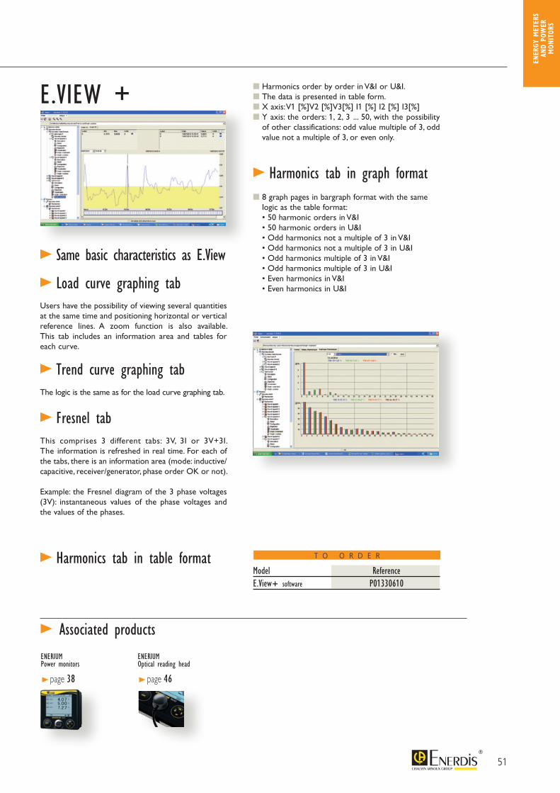
51
T O O R D E R
ENER
GY M
ETER
S AN
D PO
WER
M
ONIT
ORS
E.VIEW +
> Same basic characteristics as E.View
> Load curve graphing tabUsers have the possibility of viewing several quantities at the same time and positioning horizontal or vertical reference lines. A zoom function is also available. This tab includes an information area and tables for each curve.
> Trend curve graphing tabThe logic is the same as for the load curve graphing tab.
> Fresnel tabThis comprises 3 different tabs: 3V, 3I or 3V+3I. The information is refreshed in real time. For each of the tabs, there is an information area (mode: inductive/capacitive, receiver/generator, phase order OK or not).
Example: the Fresnel diagram of the 3 phase voltages (3V): instantaneous values of the phase voltages and the values of the phases.
> Harmonics tab in table format
Harmonics order by order in V&I or U&I. The data is presented in table form. X axis: V1 [%]V2 [%]V3[%] I1 [%] I2 [%] I3[%] Y axis: the orders: 1, 2, 3 ... 50, with the possibility
of other classifications: odd value multiple of 3, odd value not a multiple of 3, or even only.
> Harmonics tab in graph format 8 graph pages in bargraph format with the same
logic as the table format: • 50 harmonic orders in V&I • 50 harmonic orders in U&I • Odd harmonics not a multiple of 3 in V&I • Odd harmonics not a multiple of 3 in U&I • Odd harmonics multiple of 3 in V&I • Odd harmonics multiple of 3 in U&I • Even harmonics in V&I • Even harmonics in U&I
Model ReferenceE.View+ software P01330610
> Associated products
ENERIUMOptical reading head
> page 46
ENERIUMPower monitors
> page 38

52
> En
ergy
per
form
ance
Met
erin
g so
lutio
n
RENOVENERGY is a metering solution which is easy to install. The TC CLIP current transformers from Enerdis®, used with ENERIUM® power monitors or ULYS energy meters, allow renovation, modernization and the addition of metering points in existing installations.
The current transformers in the RENOVENERGY range are specially designed for easy installation on existing electrical switchboards where the available space is often limited.
The TC CLIP range of transformers, available in versions from 100 to 600 A, can be installed without disconnecting the power cables from the existing installation. This can be done without cutting off the power supply, so it is quicker.
> Description
RENOVENERGY Metering solution for renovating installations
COMPACT SOLUTION for confined environments
EASY IMPLEMENTATION without cutting off the power
COMPATIBILITY
with ULYS TTA, TT, Enerium 30 and Enerium 50
RS485, Ethernet and M-Bus COMMUNICATION
MID-certified ULYS TTA, TT for rebilling
TC CLIP transformers One Ethernet output (Modbus TCP) RS485 output(Modbus/Jbus RTU)
CER
TIFIED • C
ERTIFIED •
PRODUCT ADVANTAGES
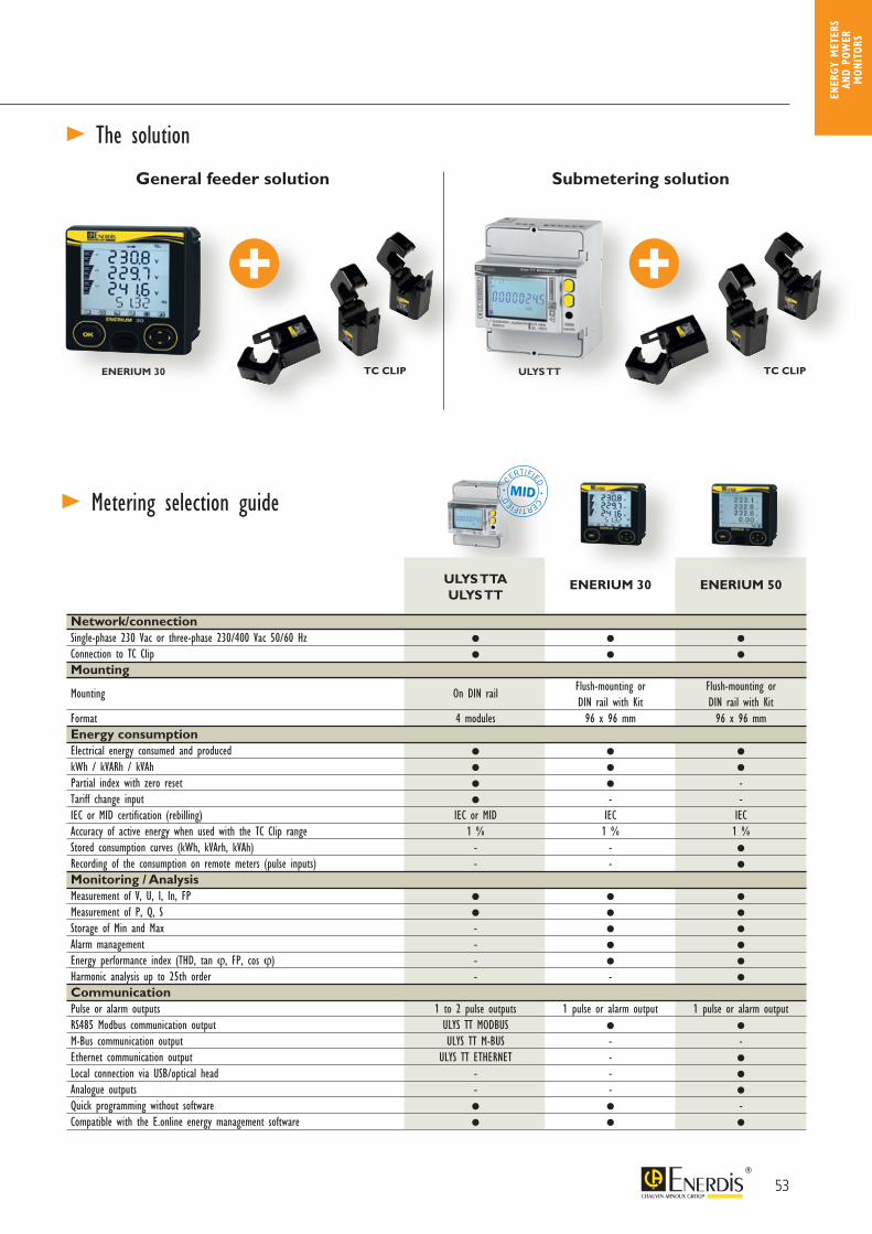
53
ENER
GY M
ETER
S AN
D PO
WER
M
ONIT
ORS
> The solution
> Metering selection guide
General feeder solution
ENERIUM 30 TC CLIP TC CLIP
Submetering solution
ULYS TTA
ULYS TT ENERIUM 30 ENERIUM 50
Network/connection Single-phase 230 Vac or three-phase 230/400 Vac 50/60 Hz
Connection to TC Clip
Mounting
Mounting On DIN rail Flush-mounting or Flush-mounting or DIN rail with Kit DIN rail with KitFormat 4 modules 96 x 96 mm 96 x 96 mmEnergy consumptionElectrical energy consumed and produced
kWh / kVARh / kVAh
Partial index with zero reset -Tariff change input - -IEC or MID certification (rebilling) IEC or MID IEC IECAccuracy of active energy when used with the TC Clip range 1 % 1 % 1 %Stored consumption curves (kWh, kVArh, kVAh) - - Recording of the consumption on remote meters (pulse inputs) - -
Monitoring / AnalysisMeasurement of V, U, I, In, FP
Measurement of P, Q, S
Storage of Min and Max -
Alarm management -
Energy performance index (THD, tan ϕ, FP, cos ϕ) -
Harmonic analysis up to 25th order - -
CommunicationPulse or alarm outputs 1 to 2 pulse outputs 1 pulse or alarm output 1 pulse or alarm outputRS485 Modbus communication output ULYS TT MODBUS
M-Bus communication output ULYS TT M-BUS - -Ethernet communication output ULYS TT ETHERNET -
Local connection via USB/optical head - -
Analogue outputs - -
Quick programming without software -Compatible with the E.online energy management software
CERTIFIED
• CERTIFIED
•
RENOVENERGY Metering solution for renovating installations
ULYS TT
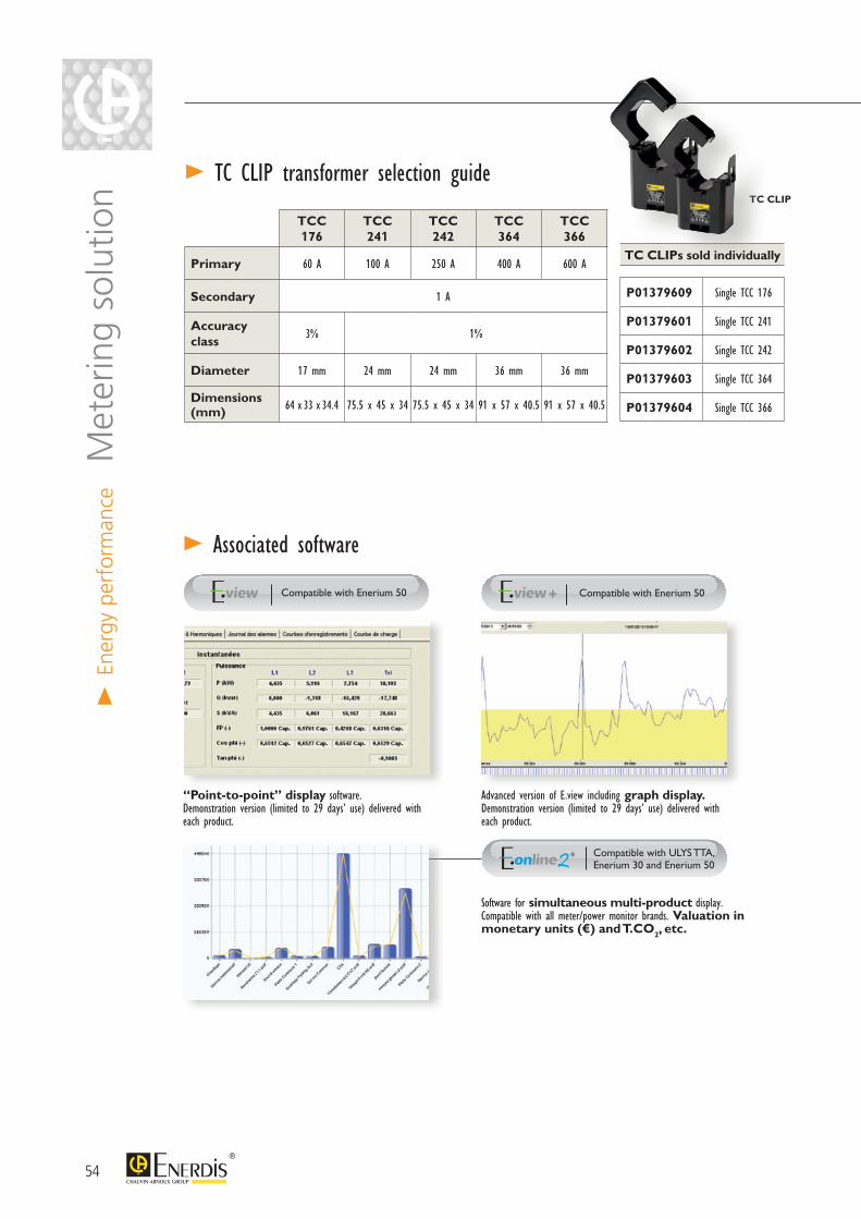
54
> En
ergy
per
form
ance
Met
erin
g so
lutio
n
TCC 176
TCC 241
TCC 242
TCC 364
TCC 366
Primary 60 A 100 A 250 A 400 A 600 A
Secondary 1 A
Accuracy class
3% 1%
Diameter 17 mm 24 mm 24 mm 36 mm 36 mm
Dimensions (mm) 64 x 33 x 34.4 75.5 x 45 x 34 75.5 x 45 x 34 91 x 57 x 40.5 91 x 57 x 40.5
TC CLIPs sold individually
P01379609 Single TCC 176
P01379601 Single TCC 241
P01379602 Single TCC 242
P01379603 Single TCC 364
P01379604 Single TCC 366
> TC CLIP transformer selection guide
“Point-to-point” display software. Demonstration version (limited to 29 days’ use) delivered with each product.
Compatible with Enerium 50
Advanced version of E.view including graph display. Demonstration version (limited to 29 days’ use) delivered with each product.
Compatible with Enerium 50
Software for simultaneous multi-product display.Compatible with all meter/power monitor brands. Valuation in monetary units (€) and T.CO2, etc.
Compatible with ULYS TTA, Enerium 30 and Enerium 50
> Associated software
TC CLIP
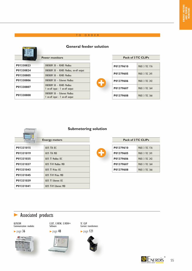
55
ENER
GY M
ETER
S AN
D PO
WER
M
ONIT
ORS
Pack of 3 TC CLIPs
P01379610 PACK 3 TCC 176
P01379605 PACK 3 TCC 241
P01379606 PACK 3 TCC 242
P01379607 PACK 3 TCC 364
P01379608 PACK 3 TCC 366
Energy meters
P01331015 ULYS TTA IEC
P01331019 ULYS TTA MID
P01331035 ULYS TT Modbus IEC
P01331037 ULYS TT-M Modbus MID
P01331043 ULYS TT M-bus IEC
P01331045 ULYS TT-M M-bus MID
P01331039 ULYS TT Ethernet IEC
P01331041 ULYS TT-M Ethernet MID
> Associated productsULYSCOM Communication modules
> page 36
E.SET, E.VIEW, E.VIEW+ Software
> page 48
TC CLIP Current transformers
> page 121
Submetering solution
General feeder solution
Pack of 3 TC CLIPs
P01379610 PACK 3 TCC 176
P01379605 PACK 3 TCC 241
P01379606 PACK 3 TCC 242
P01379607 PACK 3 TCC 364
P01379608 PACK 3 TCC 366
Power monitors
P01330823 ENERIUM 30 – RS485 Modbus
P01330824 ENERIUM 30 – RS485 Modbus, on-off output
P01330805 ENERIUM 50 – RS485 Modbus
P01330806 ENERIUM 50 – Ethernet Modbus
P01330807ENERIUM 50 – RS485 Modbus1 on-off input - 1 on-off output
P01330808ENERIUM 50 – Ethernet Modbus1 on-off input - 1 on-off output
T O O R D E R

56
Data loggers and software
Data loggersELOGWeb-box data loggerUnité de télérelève > page 58
CCTPulse receiver > page 66
ENERIUM 210 Multi-energy and multi-utility data logger > page 64
Energy management and supervision software
E.ONLINE 2 > page 68
> page 77
Processingsoftware
Communication solutions
> En
ergy
per
form
ance
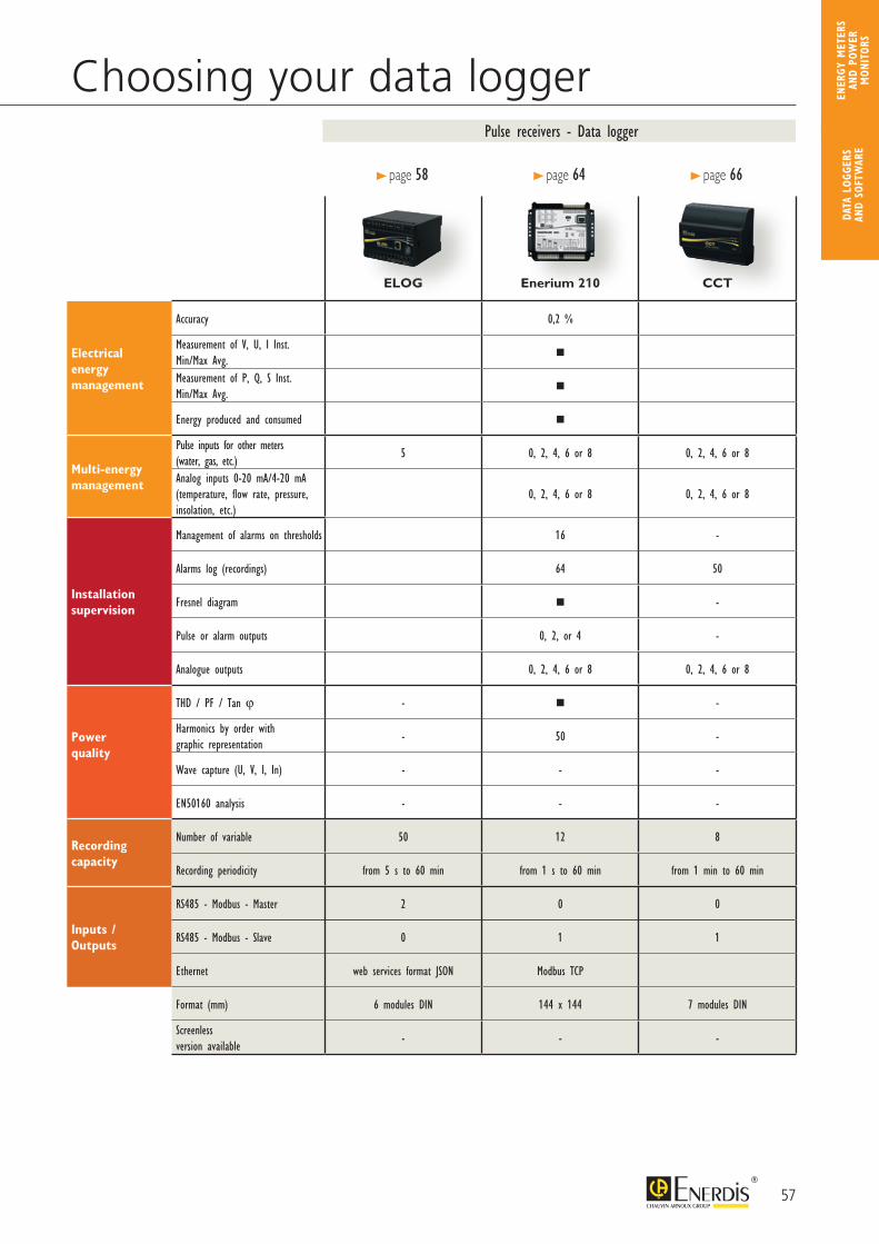
57
Choosing your data logger
ELOG Enerium 210 CCT
Electricalenergy management
Accuracy 0,2 %
Measurement of V, U, I Inst. Min/Max Avg.
Measurement of P, Q, S Inst. Min/Max Avg.
Energy produced and consumed
Multi-energymanagement
Pulse inputs for other meters (water, gas, etc.)
5 0, 2, 4, 6 or 8 0, 2, 4, 6 or 8
Analog inputs 0-20 mA/4-20 mA(temperature, flow rate, pressure, insolation, etc.)
0, 2, 4, 6 or 8 0, 2, 4, 6 or 8
Installation supervision
Management of alarms on thresholds 16 -
Alarms log (recordings) 64 50
Fresnel diagram -
Pulse or alarm outputs 0, 2, or 4 -
Analogue outputs 0, 2, 4, 6 or 8 0, 2, 4, 6 or 8
Powerquality
THD / PF / Tan ϕ - -
Harmonics by order with graphic representation
- 50 -
Wave capture (U, V, I, In) - - -
EN50160 analysis - - -
Recording capacity
Number of variable 50 12 8
Recording periodicity from 5 s to 60 min from 1 s to 60 min from 1 min to 60 min
Inputs / Outputs
RS485 - Modbus - Master 2 0 0
RS485 - Modbus - Slave 0 1 1
Ethernet web services format JSON Modbus TCP
Format (mm) 6 modules DIN 144 x 144 7 modules DIN
Screenless version available
- - -
Pulse receivers - Data logger
> page 58 > page 64 > page 66
DATA
LOG
GERS
AN
D SO
FTW
ARE
ENER
GY M
ETER
S AN
D PO
WER
M
ONIT
ORS
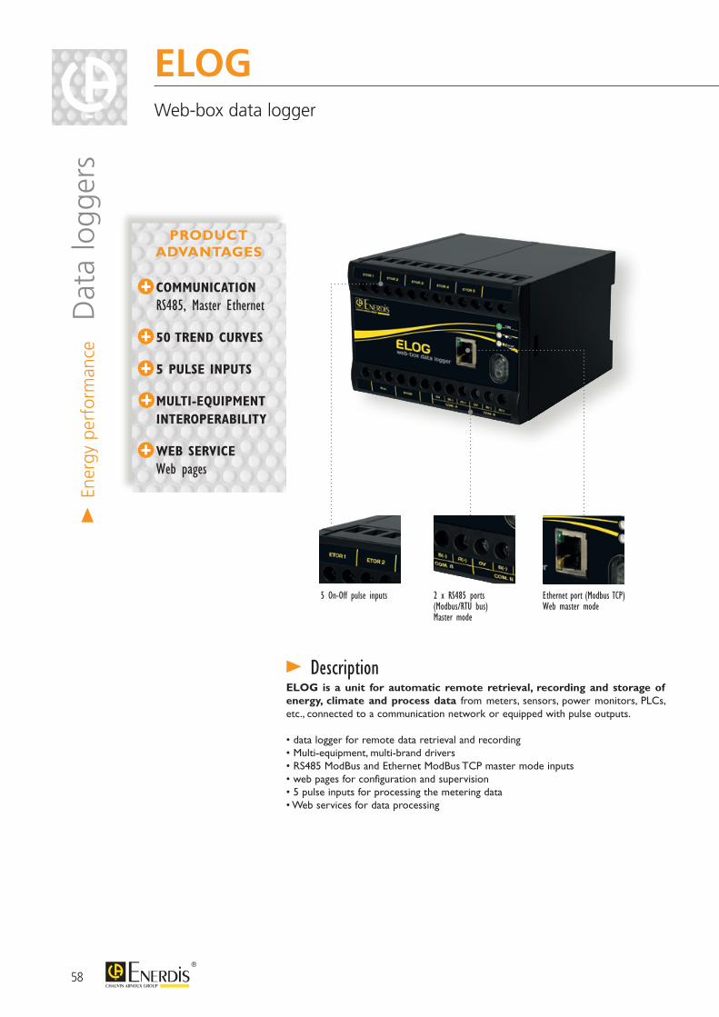
> En
ergy
per
form
ance
Dat
a lo
gger
sELOG Web-box data logger
COMMUNICATION RS485, Master Ethernet
50 TREND CURVES
5 PULSE INPUTS
MULTI-EQUIPMENT INTEROPERABILITY
WEB SERVICE Web pages
ELOG is a unit for automatic remote retrieval, recording and storage of energy, climate and process data from meters, sensors, power monitors, PLCs, etc., connected to a communication network or equipped with pulse outputs.
• data logger for remote data retrieval and recording• Multi-equipment, multi-brand drivers• RS485 ModBus and Ethernet ModBus TCP master mode inputs• web pages for configuration and supervision• 5 pulse inputs for processing the metering data• Web services for data processing
2 x RS485 ports(Modbus/RTU bus)Master mode
Ethernet port (Modbus TCP)Web master mode
5 On-Off pulse inputs
> Description
PRODUCT ADVANTAGES
58
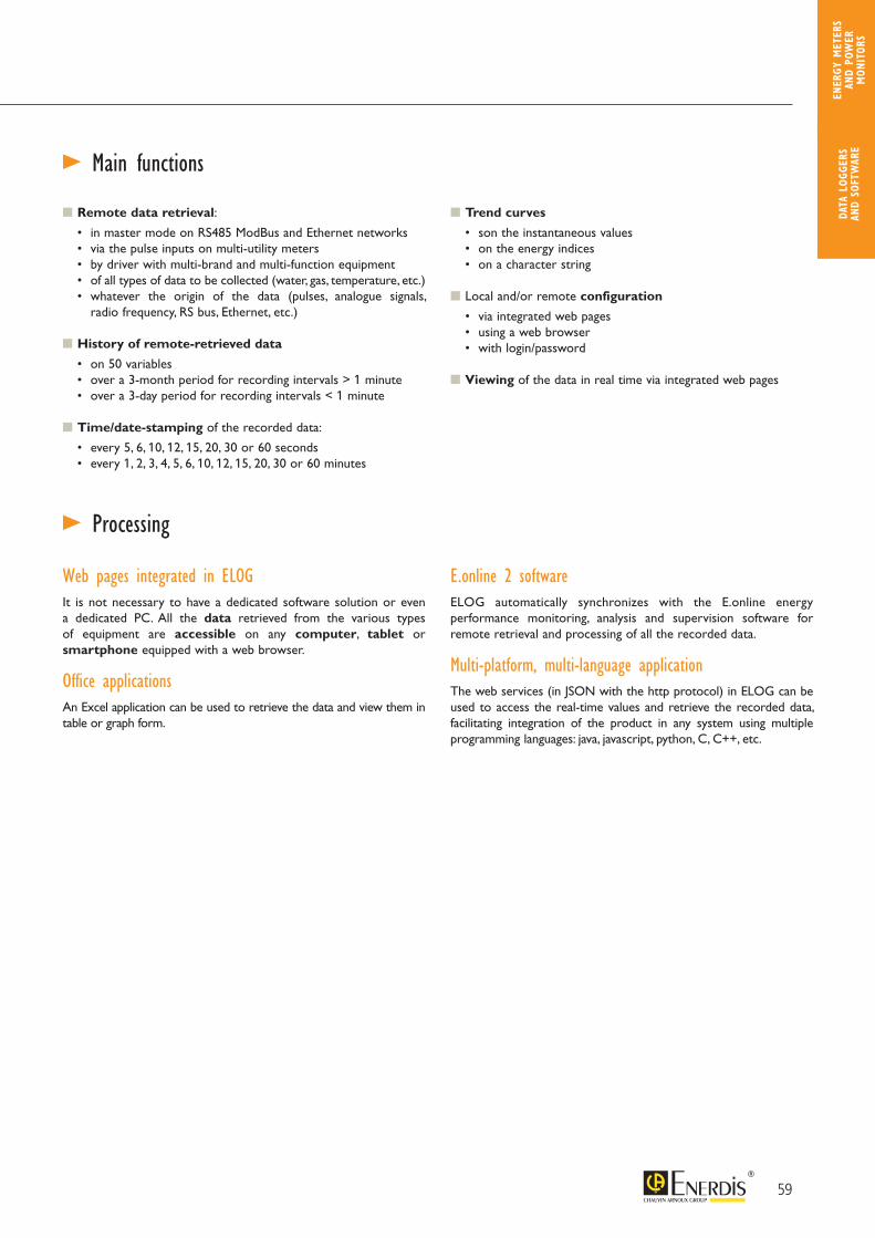
ELOG Web-box data logger
Web pages integrated in ELOG It is not necessary to have a dedicated software solution or even a dedicated PC. All the data retrieved from the various types of equipment are accessible on any computer, tablet or smartphone equipped with a web browser.
Office applicationsAn Excel application can be used to retrieve the data and view them in table or graph form.
E.online 2 softwareELOG automatically synchronizes with the E.online energy performance monitoring, analysis and supervision software for remote retrieval and processing of all the recorded data.
Multi-platform, multi-language applicationThe web services (in JSON with the http protocol) in ELOG can be used to access the real-time values and retrieve the recorded data, facilitating integration of the product in any system using multiple programming languages: java, javascript, python, C, C++, etc.
> Main functions
> Processing
Remote data retrieval:
• in master mode on RS485 ModBus and Ethernet networks • via the pulse inputs on multi-utility meters • by driver with multi-brand and multi-function equipment • of all types of data to be collected (water, gas, temperature, etc.) • whatever the origin of the data (pulses, analogue signals,
radio frequency, RS bus, Ethernet, etc.)
History of remote-retrieved data
• on 50 variables • over a 3-month period for recording intervals > 1 minute • over a 3-day period for recording intervals < 1 minute
Time/date-stamping of the recorded data:
• every 5, 6, 10, 12, 15, 20, 30 or 60 seconds • every 1, 2, 3, 4, 5, 6, 10, 12, 15, 20, 30 or 60 minutes
Trend curves
• son the instantaneous values • on the energy indices • on a character string
Local and/or remote configuration
• via integrated web pages • using a web browser • with login/password
Viewing of the data in real time via integrated web pages
59
DATA
LOG
GERS
AN
D SO
FTW
ARE
ENER
GY M
ETER
S AN
D PO
WER
M
ONIT
ORS
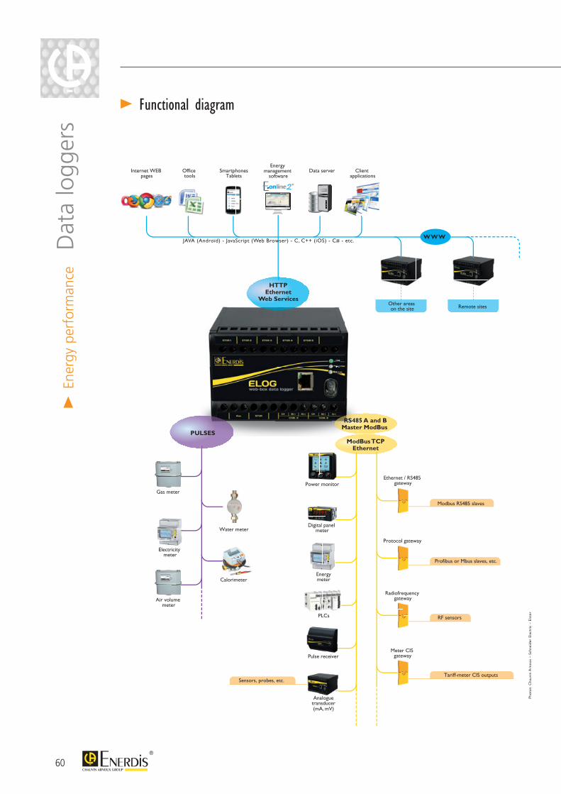
> Functional diagram
ModBus TCPEthernet
Digital panel meter
Power monitor
Pulse receiver
PLCs
Electricity meter
Energymeter
Ethernet / RS485 gateway
Protocol gateway
Radiofrequency gateway
Meter CIS gateway
Analogue transducer (mA, mV)
Sensors, probes, etc.
Modbus RS485 slaves
Profibus or Mbus slaves, etc.
RF sensors
Tariff-meter CIS outputs
RS485 A and BMaster ModBus
HTTPEthernet
Web Services
Internet WEB pages
Office tools
Energy management
softwareSmartphones
Tablets
JAVA (Androïd) - JavaScript (Web Browser) - C, C++ (iOS) - C# - etc.
Data server
Other areas on the site
Client applications
WWW
PULSES
Gas meter
Air volume meter
Water meter
Calorimeter
Pho
tos:
Cha
uvin
Arn
oux
– S
chne
ider
Ele
ctri
c –
Elst
er
Remote sites
> En
ergy
per
form
ance
Dat
a lo
gger
s
60
> Inputs / Outputs 5 pulse inputs (on-off) • for connecting the metering pulse outputs of the multi-utility meters (electricity, water, gas, calories, etc.) • the number of pulses emitted is proportional to the energy consumption measured by the meter • for each input, ELOG continuously calculates and stores the consumption data
2 x RS485 serial ports • ModBus protocol in master mode • for real-time readings of the variables and continuous recording of the values • to communicate with multi-brand equipment compatible with the ModBus protocol
1 x RJ45 Ethernet port • in ModBus TCP master mode: for real-time readings of the variables and continuous recording of the values • in web server mode: for configuring ELOG and viewing the variables in real time • in Ethernet network mode: for integration in a global Ethernet network, remote processing of the data and retrieval of the stored data • in processing mode via the web services
> Electrical specifications
> Communication
Auxiliary power supplyAC network 80 to 265 Vac - 10 VA - 42.5 to 69 HzDC network 80 to 375 Vdc - 7 W
InputsNumber of input 5Operating mode metering pulse input
Pulse interpretation
logic level 1: 12 to 72 Vdclogic level 0: 0 to 5 Vdc
pulse duration: 30 ms min. at level 1 and then 30 ms min. at level 0frequency : 0 to 16.67 Hz
Communication interfaces
RS485 A and RS485 B
type: 2 or 3-wire RS485 (shielding)protocol: ModBus RTU mode
operation: master mode - half duplexreference standard: EIA485
Ethernet type: RJ45 - 8 pins
Protocols: HTTP in slave mode - ModBus TCP, encapsulated ModBus TCP in master modespeed: 10-100 baseT
Storage
Recording periodicityevery 1, 2, 3, 4, 5, 6, 10, 12, 15, 20, 30 and 60 minutes
every 5, 6, 10, 12, 15, 20, 30 and 60 seconds
Depth 3 months on per-minute data - 3 days on per-second data
Storage mode Interchangeable memory card
Capacity 8 GBImmunity to micro-outages 2.5 sec power reserve (at 230 Vac)
ClockAccuracy ±20 ppm (±20 sec every 11.5 days)NTP synchronization yes
Back-up 30 days max. in the absence of an auxiliary power source
61
DATA
LOG
GERS
AN
D SO
FTW
ARE
ENER
GY M
ETER
S AN
D PO
WER
M
ONIT
ORS
> Functional limitsMax. number of configurable drivers 100
Number of simple variables per driver 30
Number of composite variables per driver 10
Max. number of devices. 100
Max. number of trend curves 50
Dimensions 120.5 x 120 x 81 mm (D x L x H)
Weight 560 g
Number of terminals 24 (20 used)
Connection screw terminal strip
Cable cross-section 6 mm² single-strand - 4 mm² multi-strand
Tightening torque 0.4 Nm maximum admissible on the terminal
> Mechanical specifications
> Environmental constraintsClimatic constraints
Rated operating temperature -10 to +45°C
Operating temperature limit -25 to +55°C
Storage temperature -25 to +70°C
Relative humidity as per IEC 62052-11 (standard for electrical metering applications)
<75%, annual average95% for 30 days spread naturally over the year
85% occasionally on other days
Safety constraints
Standard IEC 61010-1
Installation category III
Pollution degree 2
Behaviour in fire Complies with the UL94 standard, severity level V1
Mechanical constraints
Protection rating according to IEC 60529 IP 20
Electromagnetic constraints
StandardsIEC 62052-11 / IEC 61000-4-2 / IEC 61000-4-3 / IEC 61000-4-4 / IEC 61000-4-5 /
IEC 61000-4-6 / IEC 61000-4-8 / IEC 61000-4-11 / CISPR22
> En
ergy
per
form
ance
Dat
a lo
gger
s
62
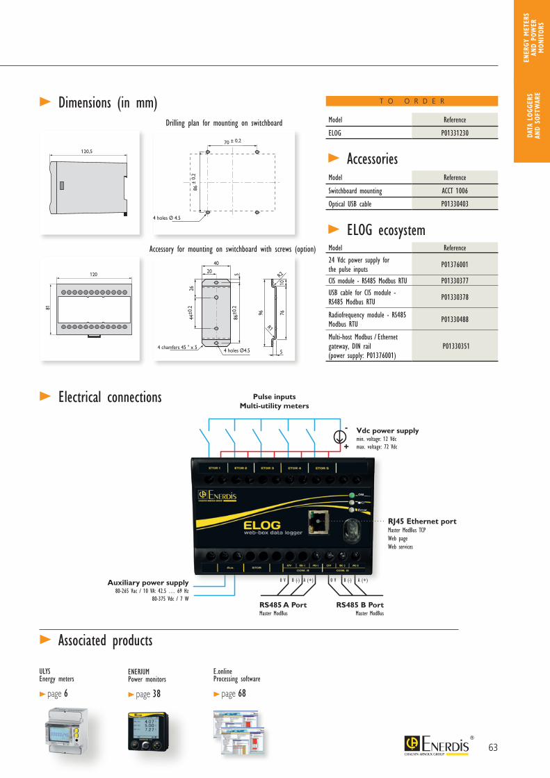
20
4 chamfers 45 ° x 5 4 holes Ø4.5
R1
R2
40
86±0
.25
7610
2644
±0.2
96
5
86
±0
.2
86
±0
.2
T11, TSPI et TSPU
Panel drilling diagram for plate mounting
Accessory for plate mounting with screw (option)
T12, T13, T21, T22, T23, T31, T32 et T33T11, TSPU et TSPI
T12, T13, T21, T22, T23, T31, T32 et T33
4 holes ø 4.5
70±0.2
60 120
120.5
8181
> Dimensions (in mm)
> Electrical connections
> AccessoriesDrilling plan for mounting on switchboard
Accessory for mounting on switchboard with screws (option)
20
4 chamfers 45° x 5 4 holes Ø 4.5
R1
R2
40
86±0
.25
7610
2644
±0.2
96
5
86
±0
.2
T11, TSPI et TSPU
Accessory for plate mounting with screw (option)
T12, T13, T21, T22, T23, T31, T32 et T33
T12, T13, T21, T22, T23, T31, T32 et T33
4 holes Ø 4.5
70±0.2
60 120
120.5
8181
86 ±
0,2
70 ± 0,2
20
4 chamfers 45 ° x 5 4 holes Ø4.5
R1
R2
40
86±0
.25
7610
2644
±0.2
96
5
86
±0
.2
86
±0
.2
T11, TSPI et TSPU
Panel drilling diagram for plate mounting
Accessory for plate mounting with screw (option)
T12, T13, T21, T22, T23, T31, T32 et T33T11, TSPU et TSPI
T12, T13, T21, T22, T23, T31, T32 et T33
4 holes ø 4.5
70±0.2
60 120
120.5
8181
120,5
20
4 chamfers 45 ° x 5 4 holes Ø4.5
R1
R2
40
86±0
.25
7610
2644
±0.2
96
5
86
±0
.2
86
±0
.2
T11, TSPI et TSPU
Panel drilling diagram for plate mounting
Accessory for plate mounting with screw (option)
T12, T13, T21, T22, T23, T31, T32 et T33T11, TSPU et TSPI
T12, T13, T21, T22, T23, T31, T32 et T33
4 holes ø 4.5
70±0.2
60 120
120.5
8181
ULYS Energy meters
> page 6
E.online Processing software
> page 68
> Associated products
Model Reference
ELOG P01331230
Model Reference
Switchboard mounting ACCT 1006
Optical USB cable P01330403
T O O R D E R
ENERIUMPower monitors
> page 38
Max. number of configurable drivers 100
Number of simple variables per driver 30
Number of composite variables per driver 10
Max. number of devices. 100
Max. number of trend curves 50
Dimensions 120.5 x 120 x 81 mm (D x L x H)
Weight 560 g
Number of terminals 24 (20 used)
Connection screw terminal strip
Cable cross-section 6 mm² single-strand - 4 mm² multi-strand
Tightening torque 0.4 Nm maximum admissible on the terminal
Climatic constraints
Rated operating temperature -10 to +45°C
Operating temperature limit -25 to +55°C
Storage temperature -25 to +70°C
Relative humidity as per IEC 62052-11 (standard for electrical metering applications)
<75%, annual average95% for 30 days spread naturally over the year
85% occasionally on other days
Safety constraints
Standard IEC 61010-1
Installation category III
Pollution degree 2
Behaviour in fire Complies with the UL94 standard, severity level V1
Mechanical constraints
Protection rating according to IEC 60529 IP 20
Electromagnetic constraints
StandardsIEC 62052-11 / IEC 61000-4-2 / IEC 61000-4-3 / IEC 61000-4-4 / IEC 61000-4-5 /
IEC 61000-4-6 / IEC 61000-4-8 / IEC 61000-4-11 / CISPR22
Vdc power supplymin. voltage: 12 Vdcmax. voltage: 72 Vdc
Pulse inputsMulti-utility meters
Auxiliary power supply80-265 Vac / 10 VA: 42.5 … 69 Hz
80-375 Vdc / 7 WRS485 A Port Master ModBus
RS485 B PortMaster ModBus
0 V B (-) A (+) 0 V B (-) A (+)
-
+
RJ45 Ethernet portMaster ModBus TCPWeb pageWeb services
> ELOG ecosystemModel Reference
24 Vdc power supply for the pulse inputs P01376001
CIS module - RS485 Modbus RTU P01330377
USB cable for CIS module - RS485 Modbus RTU P01330378
Radiofrequency module - RS485 Modbus RTU P01330488
Multi-host Modbus / Ethernet gateway, DIN rail (power supply: P01376001)
P01330351
63
DATA
LOG
GERS
AN
D SO
FTW
ARE
ENER
GY M
ETER
S AN
D PO
WER
M
ONIT
ORS

ENERIUM 210 Multi-energy, multi-utility data logger
> En
ergy
per
form
ance
Dat
a lo
gger
s
8 INPUTS for acquisition: - On-off - analogue
ETHERNET & RS485
COMMUNICATION
MULTI-ENERGY and multi-utility
ENERIUM 210 is a multi-energy data logger which continuously records the data from meters (pulse output) or temperature or flow-rate sensors (0-20 mA / 4-20 mA signals). Equipped as standard with an RS485 ModBus or Ethernet ModBus TCP output, it allows remote data retrieval.
• Recording (8 load curves / 4 trend curves)
• Multi-energy consumption indices and curves (water, gas, electricity, etc.)
• Temperature curves
• Trend curves
> Further information
Ethernet output(Modbus TCP)RS485 output(Modbus/Jbus RTU)
Programming and read-ing of the data by opti-cal head
> Description
PRODUCT ADVANTAGES
64
ENERIUM 210 Multi-energy, multi-utility data logger
ULYS Energy meters
> page 6
E.online Processing software
> page 68
> Environment
> Software
Model Reference
Enerium 210 - 50/60 Hz - 80 to 265 Vac P01330835
/ 110 to 375 Vdc - Ethernet - 8 metering inputs
For the RS485 version, please contact us
Operating temperature -10°C to +55°C (K55 according to EN 61557-12)Storage temperature -25°C to +70°CRelative humidity 95% to 40°CInstallation category 3Pollution degree 2Behaviour in fire UL94, severity V1
> Mechanical specificationsWeight 700 gMounting DIN-rail or plate mountingConnection screw terminal strip
> Electrical connections
> Electrical specificationsAuxiliary power supplySupply voltage 80 to 265 Vac / 110 to 375 Vdc
Consumption 20 VA / 10 W
Digital inputs (on-off or pulses)
Operating voltage High level: 10 to 110 Vdc
Low level: 0 to 5 Vdc
Min. signal width High level: 30 ms
Low level: 30 ms
Consumption < 0.5 W
Ethernet output Type RJ45 – 8 pins
Protocol ModBus/TCP
Speed (configurable) Compatible with 10, 100 and 1000 base T
networks
> Associated products
> Dimensions (in mm)
Please see > page 42
T O O R D E R
Accessory ReferenceOptical head P01330401
Model ReferenceE.view P01330601E.view+ / E.online 2 Consult us
Optical head is compulsory to configure the IP adress
65
DATA
LOG
GERS
AN
D SO
FTW
ARE
ENER
GY M
ETER
S AN
D PO
WER
M
ONIT
ORS
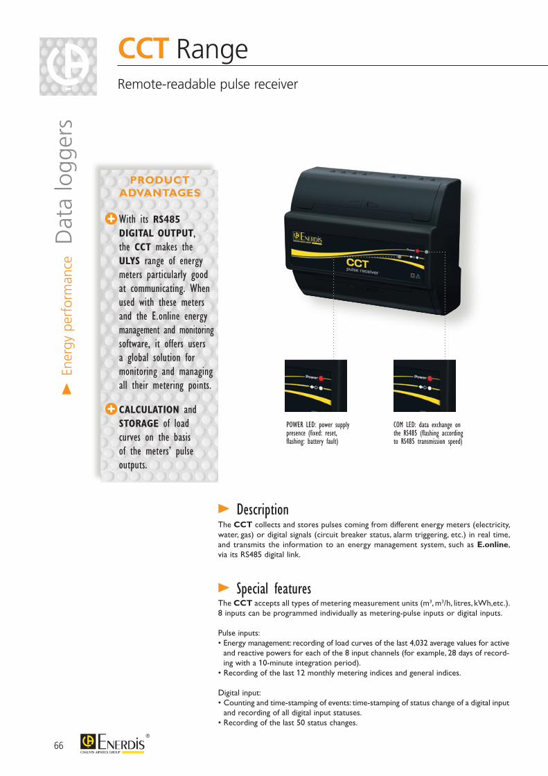
The CCT collects and stores pulses coming from different energy meters (electricity, water, gas) or digital signals (circuit breaker status, alarm triggering, etc.) in real time, and transmits the information to an energy management system, such as E.online, via its RS485 digital link.
The CCT accepts all types of metering measurement units (m3, m3/h, litres, kWh,etc.). 8 inputs can be programmed individually as metering-pulse inputs or digital inputs.
Pulse inputs:• Energy management: recording of load curves of the last 4,032 average values for active
and reactive powers for each of the 8 input channels (for example, 28 days of record-ing with a 10-minute integration period).
• Recording of the last 12 monthly metering indices and general indices.
Digital input:• Counting and time-stamping of events: time-stamping of status change of a digital input
and recording of all digital input statuses.• Recording of the last 50 status changes.
> Special features
> Description
CCT RangeRemote-readable pulse receiver
> En
ergy
per
form
ance D
ata
logg
ers
COM LED: data exchange on the RS485 (flashing according to RS485 transmission speed)
POWER LED: power supply presence (fixed: reset, flashing: battery fault)
With its RS485 DIGITAL OUTPUT, the CCT makes the ULYS range of energy meters particularly good at communicating. When used with these meters and the E.online energy management and monitoring software, it offers users a global solution for monitoring and managing all their metering points.
CALCULATION and STORAGE of load curves on the basis of the meters’ pulse outputs.
PRODUCT ADVANTAGES
66
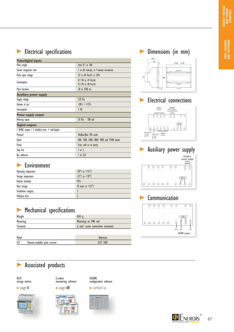
44
53,5
5
45 100
6
122,5 (7 M)
18 17 16 15
1 2 3 4 5 6
14 13 12 11
87 9 10
InputsGroup B
InputsGroup A
OutputsPower supply for dry contact 24 Vdc
Density (OV)at inputsgroup B
Density (OV) at inputsgroup A
44
53,5
5
45 100
6
122,5 (7 M)
18 17 16 15
1 2 3 4 5 6
14 13 12 11
87 9 10
B(-)A(+) OV
Entréesgroupe B
Entréesgroupe A
SortiesAlimentation pourcontact sec 24 Vdc
Auxiliary power supply
230 Vac
Sortie RS485
Masse (OV) des entréesdu groupe B
Masse (OV)des entrées du groupe A44
53,5
5
45 100
6
122,5 (7 M)
18 17 16 15
1 2 3 4 5 6
14 13 12 11
87 9 10
B(-)A(+) OV
RS485 output
44
53,5
5
45 100
6
122,5 (7 M)
18 17 16 15
1 2 3 4 5 6
14 13 12 11
87 9 10
Entréesgroupe B
Entréesgroupe A
SortiesAlimentation pourcontact sec 24 Vdc
Masse (OV) des entréesdu groupe B
Masse (OV)des entrées du groupe A
> Mechanical specifications
> Electrical specifications
Weight 450 gMounting Mounting on DIN railTerminal 6 mm2 screw connection terminals
> EnvironmentOperating temperature -20°C to +55°CStorage temperature -25°C to +70°CRelative humidity 95%Data storage 10 years at +25°CInstallation category 3Pollution level 2
> Dimensions (in mm)
> Electrical connections
> Auxiliary power supply
> Communication
Pulse/digital inputs Pulse weight from 0.1 to 100
Stream integration time 1 to 60 minutes, in 1-minute increments
Pulse input voltage 24 to 60 Vac/dc ± 20%
Consumption 0.1 VA to 24 Vac/dc 0.5 VA to 48 Vac/dc
Pulse duration 30 to 1500 ms
Auxiliary power supplySupply voltage 230 Vac
Domain of use -20% / +15%
Consumption 5 VA
Power supply outputMetering inputs 24 Vdc – 100 mA
Digital outputs 1 RS485 output / 2 shielded wires + half-duplex
Protocol ModBus/JBus RTU mode
Speed 600, 1200, 2400, 4800, 9600 and 19200 bauds
Parity Even, odd or no parity
Stop bits 1 or 2
Bus addresses 1 to 255
> Associated products
ULYS energy meters
> page 6
E.online monitoring software
> page 68
SESAME configuration software
> contact us
Model ReferenceCCT Remote-readable pulse receiver CCCT 1001
67
DATA
LOG
GERS
AN
D SO
FTW
ARE
ENER
GY M
ETER
S AN
D PO
WER
M
ONIT
ORS
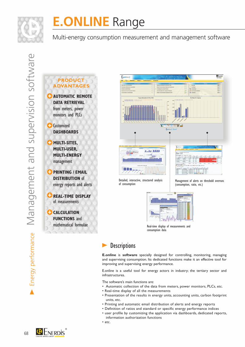
> En
ergy
per
form
ance
Man
agem
ent
and
supe
rvis
ion
soft
war
eE.ONLINE RangeMulti-energy consumption measurement and management software
AUTOMATIC REMOTE DATA RETRIEVAL from meters, power monitors and PLCs
Customized DASHBOARDS
MULTI-SITES, MULTI-USER, MULTI-ENERGY management
PRINTING / EMAIL DISTRIBUTION of energy reports and alerts
REAL-TIME DISPLAY of measurements
CALCULATION FUNCTIONS and mathematical formulae
Detailed, interactive, structured analysis of consumption
Real-time display of measurements and consumption data
Management of alerts on threshold overruns (consumption, ratio, etc.)
E.online is software specially designed for controlling, monitoring, managing and supervising consumption. Its dedicated functions make it an effective tool for improving and supervising energy performance.
E.online is a useful tool for energy actors in industry; the tertiary sector and infrastructures.
The software’s main functions are:• Automatic collection of the data from meters, power monitors, PLCs, etc.• Real-time display of all the measurements• Presentation of the results in energy units, accounting units, carbon footprint
units, etc.• Printing and automatic email distribution of alerts and energy reports• Definition of ratios and standard or specific energy performance indices• user profile by customizing the application via dashboards, dedicated reports,
information authorization functions• etc.
> Descriptions
PRODUCT ADVANTAGES
68
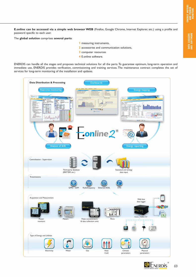
Real-time monitoring
Dashboards
Energy mapping
2
Third-party database(ERP, TBM, etc.)
Statistical and energy data input
Electricity Water Gas Heat Cold
Climatic parameters
Physical parameters
0
1 5
32 4 5
6
0
1 5
32 4 5
6
0
1 5
32 4 5
6
0
1 5
32 4 5
6
0
1 5
32 4 5
6
0
1 5
32 4 5
6
Powermonitors
Meters Pulse concentrators& data collection units
PLCs
Web boxdata logger
Radiofrequency STNEthernet ADSLGPRS - GSM
Analysis of drift Energy reporting
Modbus / Modbus TCP
Centralization - Supervision
Data Distribution & Processing
Transmissions
Type of Energy and Utilities
Acquisition and Measurement
E.ONLINE RangeMulti-energy consumption measurement and management software E.online can be accessed via a simple web browser WEB (Firefox, Google Chrome, Internet Explorer, etc.) using a profile and
password specific to each user.
The global solution comprises several parts:
ENERDIS can handle all the stages and proposes technical solutions for all the parts. To guarantee optimum, long-term operation and immediate use, ENERDIS provides verification, commissioning and training services. The maintenance contract completes the set of services for long-term monitoring of the installation and updates.
1 measuring instruments,
2 accessories and communication solutions,
3 computer resources
4 E.online software.
69
DATA
LOG
GERS
AN
D SO
FTW
ARE
ENER
GY M
ETER
S AN
D PO
WER
M
ONIT
ORS
This symbol identifies major advantages.
> En
ergy
per
form
ance
Man
agem
ent
and
supe
rvis
ion
soft
war
e
Dashboard This can be customized for each E.online2 user profile. On a single page, it provides a real-time overview of the changes in consumption compared with a history, displays the alarms in progress and constantly updates the energy reports defined.
> Description
1
5
2
4 3
1
2
3
4
5
Real-time evolution of the measurements, consumption data, ratios, indices, etc. Display of the values for hours, days and months Immediate comparison with the history: day-1, month-1, year-1 Tracing of the temperature, performance indicator, etc., with superimposed curves
Real-time evolution of the consumption data by energy usage, utility, category, building, industrial process, etc.
Display for the current day, month or year Immediate comparison with history of day-1, month-1 and/or year-1
Display of alarms in progress Access to the alarms log (details of the alarms, acknowledgement function)
Display of constantly-updated analyses and reports
Access to customized pages for viewing real-time measurements
70
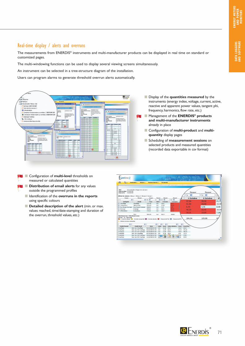
Real-time display / alerts and overrunsThe measurements from ENERDIS® instruments and multi-manufacturer products can be displayed in real time on standard orcustomized pages.
The multi-windowing functions can be used to display several viewing screens simultaneously.
An instrument can be selected in a tree-structure diagram of the installation.
Users can program alarms to generate threshold overrun alerts automatically.
Display of the quantities measured by the instruments (energy index, voltage, current, active, reactive and apparent power values, tangent phi, frequency, harmonics, flow rate, etc.)
Management of the ENERDIS® products and multi-manufacturer instruments already in place
Configuration of multi-product and multi-quantity display pages
Scheduling of measurement sessions on selected products and measured quantities (recorded data exportable in csv format)
Configuration of multi-level thresholds on measured or calculated quantities
Distribution of email alerts for any values outside the programmed profiles
Identification of the overruns in the reports using specific colours
Detailed description of the alert (min. or max. values reached, time/date-stamping and duration of the overrun, threshold values, etc.)
71
DATA
LOG
GERS
AN
D SO
FTW
ARE
ENER
GY M
ETER
S AN
D PO
WER
M
ONIT
ORS
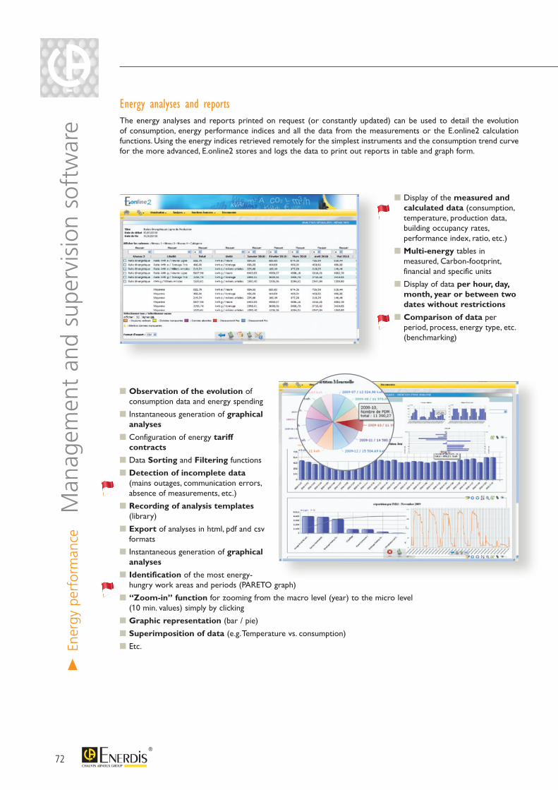
> En
ergy
per
form
ance
Man
agem
ent
and
supe
rvis
ion
soft
war
eEnergy analyses and reportsThe energy analyses and reports printed on request (or constantly updated) can be used to detail the evolution of consumption, energy performance indices and all the data from the measurements or the E.online2 calculation functions. Using the energy indices retrieved remotely for the simplest instruments and the consumption trend curve for the more advanced, E.online2 stores and logs the data to print out reports in table and graph form.
Display of the measured and calculated data (consumption, temperature, production data, building occupancy rates, performance index, ratio, etc.)
Multi-energy tables in measured, Carbon-footprint, financial and specific units
Display of data per hour, day, month, year or between two dates without restrictions
Comparison of data per period, process, energy type, etc. (benchmarking)
Observation of the evolution of consumption data and energy spending
Instantaneous generation of graphical analyses
Configuration of energy tariff contracts
Data Sorting and Filtering functions
Detection of incomplete data (mains outages, communication errors, absence of measurements, etc.)
Recording of analysis templates (library)
Export of analyses in html, pdf and csv formats
Instantaneous generation of graphical analyses
Identification of the most energy-hungry work areas and periods (PARETO graph)
“Zoom-in” function for zooming from the macro level (year) to the micro level (10 min. values) simply by clicking
Graphic representation (bar / pie)
Superimposition of data (e.g. Temperature vs. consumption)
Etc.
72
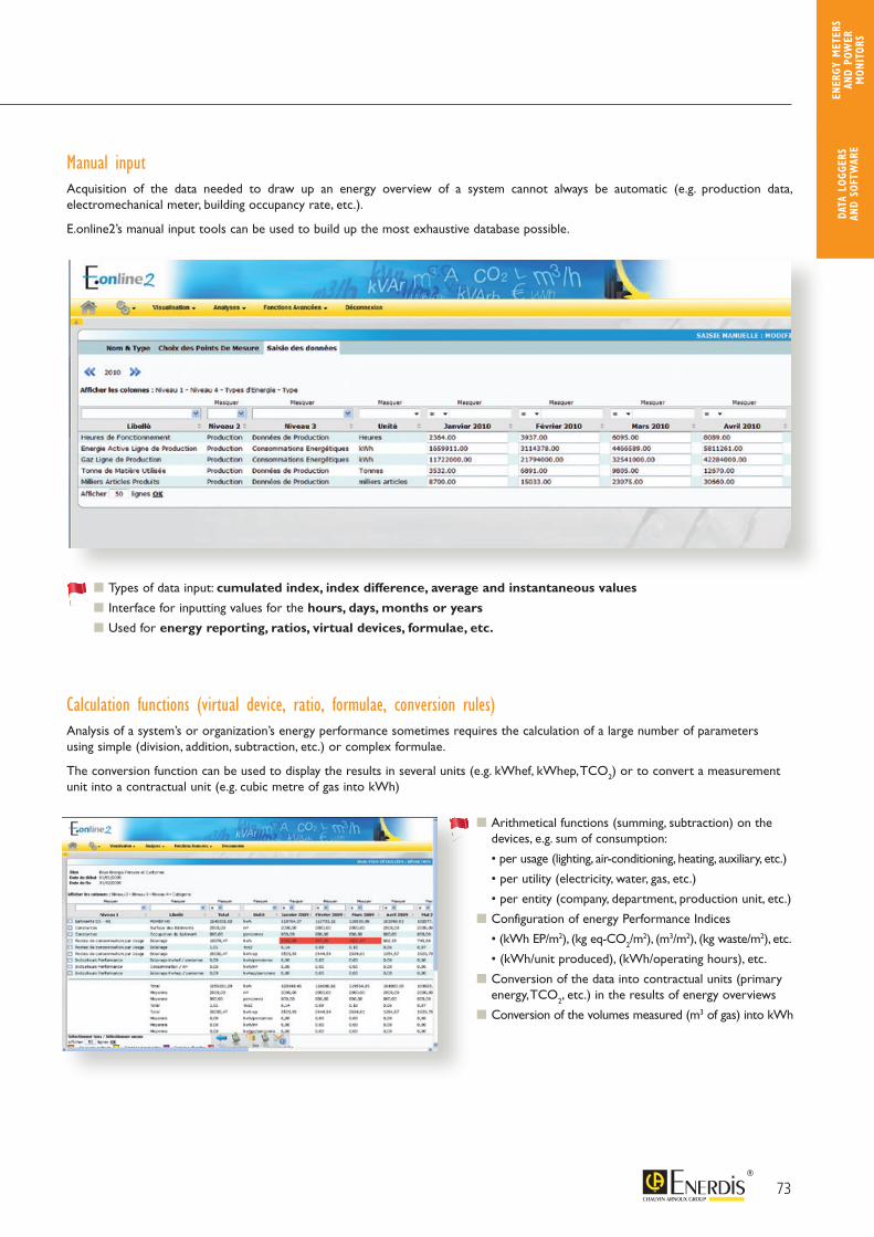
Manual inputAcquisition of the data needed to draw up an energy overview of a system cannot always be automatic (e.g. production data, electromechanical meter, building occupancy rate, etc.).
E.online2’s manual input tools can be used to build up the most exhaustive database possible.
Types of data input: cumulated index, index difference, average and instantaneous values
Interface for inputting values for the hours, days, months or years
Used for energy reporting, ratios, virtual devices, formulae, etc.
Calculation functions (virtual device, ratio, formulae, conversion rules)Analysis of a system’s or organization’s energy performance sometimes requires the calculation of a large number of parametersusing simple (division, addition, subtraction, etc.) or complex formulae.
The conversion function can be used to display the results in several units (e.g. kWhef, kWhep, TCO2) or to convert a measurementunit into a contractual unit (e.g. cubic metre of gas into kWh)
Arithmetical functions (summing, subtraction) on the devices, e.g. sum of consumption:
• per usage (lighting, air-conditioning, heating, auxiliary, etc.)
• per utility (electricity, water, gas, etc.)
• per entity (company, department, production unit, etc.)
Configuration of energy Performance Indices
• (kWh EP/m2), (kg eq-CO2/m2), (m3/m2), (kg waste/m2), etc.
• (kWh/unit produced), (kWh/operating hours), etc.
Conversion of the data into contractual units (primary energy, TCO2, etc.) in the results of energy overviews
Conversion of the volumes measured (m3 of gas) into kWh
73
DATA
LOG
GERS
AN
D SO
FTW
ARE
ENER
GY M
ETER
S AN
D PO
WER
M
ONIT
ORS
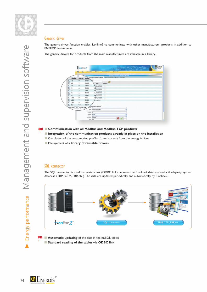
> En
ergy
per
form
ance
Man
agem
ent
and
supe
rvis
ion
soft
war
e Generic driver The generic driver function enables E.online2 to communicate with other manufacturers’ products in addition to ENERDIS instruments.
The generic drivers for products from the main manufacturers are available in a library.
Communication with all ModBus and ModBus-TCP products
Integration of the communication products already in place on the installation
Calculation of the consumption profiles (trend curves) from the energy indices
Management of a library of reusable drivers
SQL connector The SQL connector is used to create a link (ODBC link) between the E.online2 database and a third-party system database (TBM, CTM, ERP, etc.). The data are updated periodically and automatically by E.online2.
Automatic updating of the data in the mySQL tables
Standard reading of the tables via ODBC link
SQL connector TBM, CTM, ERP, etc.
74
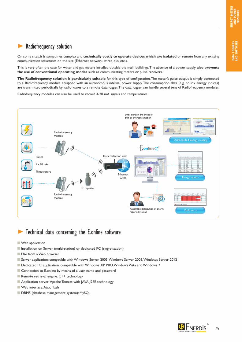
On some sites, it is sometimes complex and technically costly to operate devices which are isolatedor remote from any existing communication structures on the site (Ethernet network, wired bus, etc.).
This is very often the case for water and gas meters installed outside the main buildings. The absence of a power supply also prevents the use of conventional operating modes such as communicating meters or pulse receivers.
The Radiofrequency solution is particularly suitablefor this type of configuration. The meter’s pulse output is simply connected to a Radiofrequency module equipped with an autonomous internal power supply. The consumption data (e.g. hourly energy indices) are transmitted periodically by radio waves to a remote data logger. The data logger can handle several tens of Radiofrequency modules.
Radiofrequency modules can also be used to record 4-20 mA signals and temperatures.
Communication with all ModBus and ModBus-TCP products
Integration of the communication products already in place on the installation
Calculation of the consumption profiles (trend curves) from the energy indices
Management of a library of reusable drivers
Web application
Installation on Server (multi-station) or dedicated PC (single-station)
Use from a Web browser
Server application: compatible with Windows Server 2003, Windows Server 2008, Windows Server 2012
Dedicated PC application: compatible with Windows XP PRO, Windows Vista and Windows 7
Connection to E.online by means of a user name and password
Remote retrieval engine: C++ technology
Application server: Apache Tomcat with JAVA J2EE technology
Web interface: Ajax, Flash
DBMS (database management system): MySQL
> Technical data concerning the E.online software
> Radiofrequency solution
RF repeater
0
1 5
32 4 5
6
0
1 5
32 4 5
6
0
1 5
32 4 5
6
0
1 5
32 4 5
6
0
1 5
32 4 5
6
Automatic distribution of energy reports by email
Email alerts in the event of drift or overconsumption
Energy reports
Dashboards & energy mapping
Drift alerts
Radiofrequency module
Radiofrequency module
Pulses
4 - 20 mA
TemperatureEthernet
GPRS
Data collection unit
75
DATA
LOG
GERS
AN
D SO
FTW
ARE
ENER
GY M
ETER
S AN
D PO
WER
M
ONIT
ORS
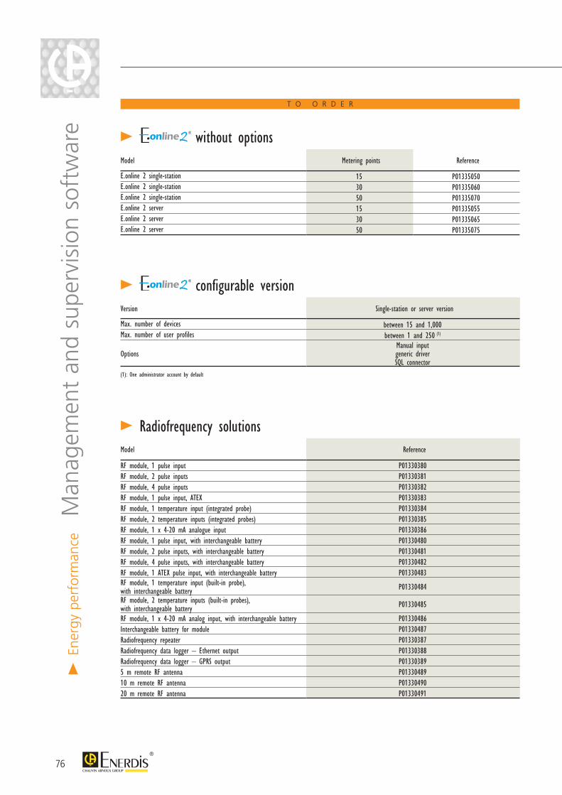
T O O R D E R
> without options
> configurable version
Model Metering points Reference
E.online 2 single-station 15 P01335050E.online 2 single-station 30 P01335060E.online 2 single-station 50 P01335070E.online 2 server 15 P01335055E.online 2 server 30 P01335065E.online 2 server 50 P01335075
Version Single-station or server version
Max. number of devices between 15 and 1,000Max. number of user profiles between 1 and 250 (1)
OptionsManual inputgeneric driverSQL connector
(1): One administrator account by default
> En
ergy
per
form
ance
Man
agem
ent
and
supe
rvis
ion
soft
war
e
> Radiofrequency solutionsModel Reference
RF module, 1 pulse input P01330380RF module, 2 pulse inputs P01330381RF module, 4 pulse inputs P01330382RF module, 1 pulse input, ATEX P01330383RF module, 1 temperature input (integrated probe) P01330384RF module, 2 temperature inputs (integrated probes) P01330385RF module, 1 x 4-20 mA analogue input P01330386RF module, 1 pulse input, with interchangeable battery P01330480RF module, 2 pulse inputs, with interchangeable battery P01330481RF module, 4 pulse inputs, with interchangeable battery P01330482RF module, 1 ATEX pulse input, with interchangeable battery P01330483RF module, 1 temperature input (built-in probe), with interchangeable battery P01330484
RF module, 2 temperature inputs (built-in probes), with interchangeable battery P01330485
RF module, 1 x 4-20 mA analog input, with interchangeable battery P01330486Interchangeable battery for module P01330487Radiofrequency repeater P01330387Radiofrequency data logger – Ethernet output P01330388Radiofrequency data logger – GPRS output P013303895 m remote RF antenna P0133048910 m remote RF antenna P0133049020 m remote RF antenna P01330491
76
> Communication solutions
Ethernet
Multi-host JBUS / Ethernet gateway, DIN rail - 24 Vdc (power supply: P01376001) P01330351
230 Vac / 24-48 Vdc 30 W power supply, DIN rail P01376001
4 x RS485 / Ethernet repeaters/dispatchers - 230 Vac P01330375
Mounting bracket for 4 x RS485/ Ethernet repeaters/dispatchers P01330374
RS485 - RJ10 cable for 4 x RS485/ Ethernet repeaters/dispatchers P01330376
5-port Ethernet switch, 10-100 BaseTx - 10 to 60 Vdc (power supply: P01376001) 01NC5503
WS250 ADSL router modem - 10 to 28 Vdc (power supply: P01376001) P01330361
DGCW 3G router modem - 230 Vac P01330370
Omnidirectional remote antenna, 3G DGCW router P01330371
Directional remote antenna, 3G DGCW router P01330372
FME-SMA adapter for directional antenna P01330373
Mounting bracket for 3G DGCW router P01330374
3G WS310 router modem - 10 to 60 Vdc (power supply: P01376001) P01330362
External antenna for 3G - WS310 - WS330 router modem P01330363
Self-powered RS485 Modbus - USB converter P01330365
Serial linkRS485/RS232 CONVERTER - DIN RAIL - 230 VAC P01330350
2 x RS485/RS485 repeaters/dispatchers - 19.2 to 28.8 Vdc (power supply: ACCJ1003) ACCJ1002
Power supply for 2 x RS485/RS485 repeaters/dispatchers ACCJ1003
4 x RS485/RS485-RS232 repeaters/dispatchers - 230 Vac ACCJ1001
STN and GSM linkSTN - RS232 desktop modem - 230 Vac MODV2000
STN modem, DIN rail, RS485, ROHS - 230 Vac P01330352
STN modem, DIN rail, RS485 - 12 Vdc (power supply: ACCJ1004) MODV2002
230 Vac/12 Vdc - 12 VA power supply ACCJ1004
STN modem, RTC DIN rail, GSM - RS485 WS - 9.6 to 57.6 Vdc (power supply: P01376001) P01330379
RadiofrequencyRF-RS485-ETH-WS80 modemRadiofrequency / RS485-RS232-Ethernet gateway / 10 to 30 Vdc (power supply: P01376001)
01NC5503
RF-RS485 Modbus RTU-WS805U modem Radiofrequency / RS485 Modbus RTU gateway /- 10 to 30 Vdc (power supply:P01376001)
01NC5503
Remote antenna for RF-RS485-ETH-WS80 and WS805U modem 01NC5503
4 m cable for remote antenna 01NC5503
FME-SMA adapter for remote antenna 01NC5503
Radiofrequency - RS485 Modbus RTU module P01330488
77
DATA
LOG
GERS
AN
D SO
FTW
ARE
ENER
GY M
ETER
S AN
D PO
WER
M
ONIT
ORS

78
Power quality analyzers
Power quality monitor
ENERIUM 300Power monitor Qualimetry according to EN50160 > page 38
Analyzers>
Pow
er Q
ualit
y
Permanent analyzers - MAP range - Class A
MAP 607 Single-phase voltage quality analyzer> page 85
MAP 610Three-phase voltage quality analyzer > page 84
MAP 620Three-phase voltage/current power quality analyzer > page 84
MAP 640Three-phase voltage/current power quality analyzer with HF transient capture > page 84
MAP CompactThree-phase voltage/current power quality analyzer + Energy - Monitoring of EN50160 template> page 91
Non-intrusive analyzers - MAP range - Class A
MAP 612-NI Non-intrusive three-phase voltage quality analyzer with quick connection> page 87
MAP 620-NINon-intrusive power analyzer - three-phase voltage/current > page 87
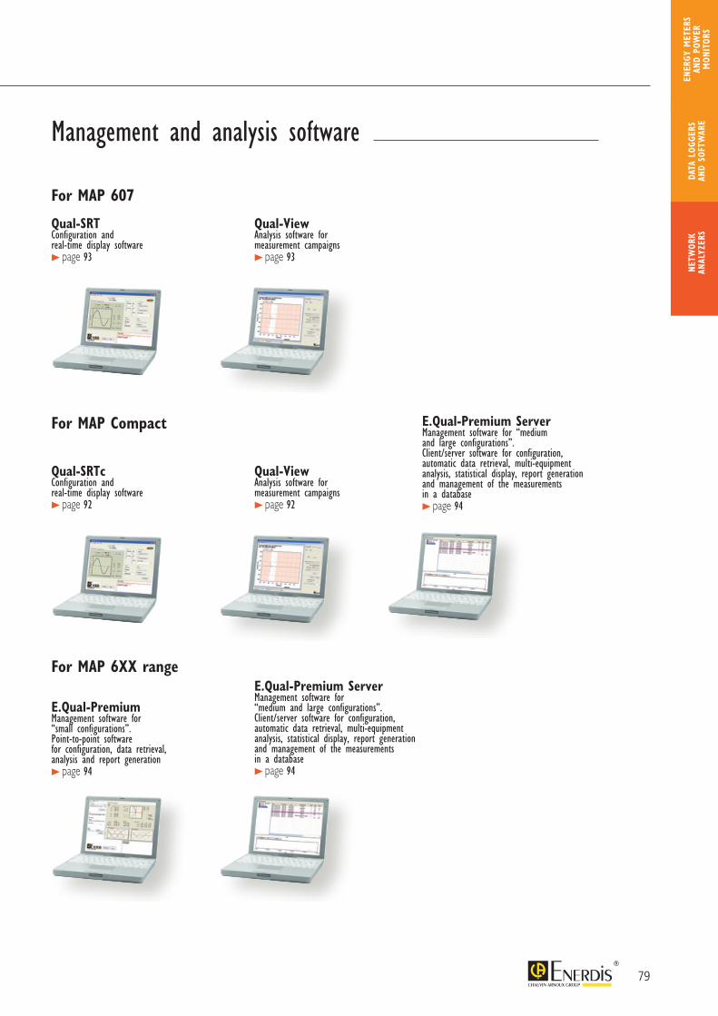
79
Management and analysis software
For MAP 607
For MAP 6XX range
For MAP Compact
Qual-SRT Configuration and real-time display software > page 93
Qual-SRTc Configuration andreal-time display software > page 92
Qual-ViewAnalysis software for measurement campaigns > page 93
Qual-ViewAnalysis software formeasurement campaigns > page 92
E.Qual-Premium Management software for “small configurations”.Point-to-point software for configuration, data retrieval, analysis and report generation > page 94
E.Qual-Premium ServerManagement software for “medium and large configurations”.Client/server software for configuration, automatic data retrieval, multi-equipment analysis, statistical display, report generation and management of the measurements in a database > page 94
E.Qual-Premium ServerManagement software for “medium and large configurations”.Client/server software for configuration, automatic data retrieval, multi-equipment analysis, statistical display, report generation and management of the measurements in a database > page 94
NETW
ORK
ANAL
YZER
SDA
TA L
OGGE
RS
AND
SOFT
WAR
E
ENER
GY M
ETER
S AN
D PO
WER
M
ONIT
ORS
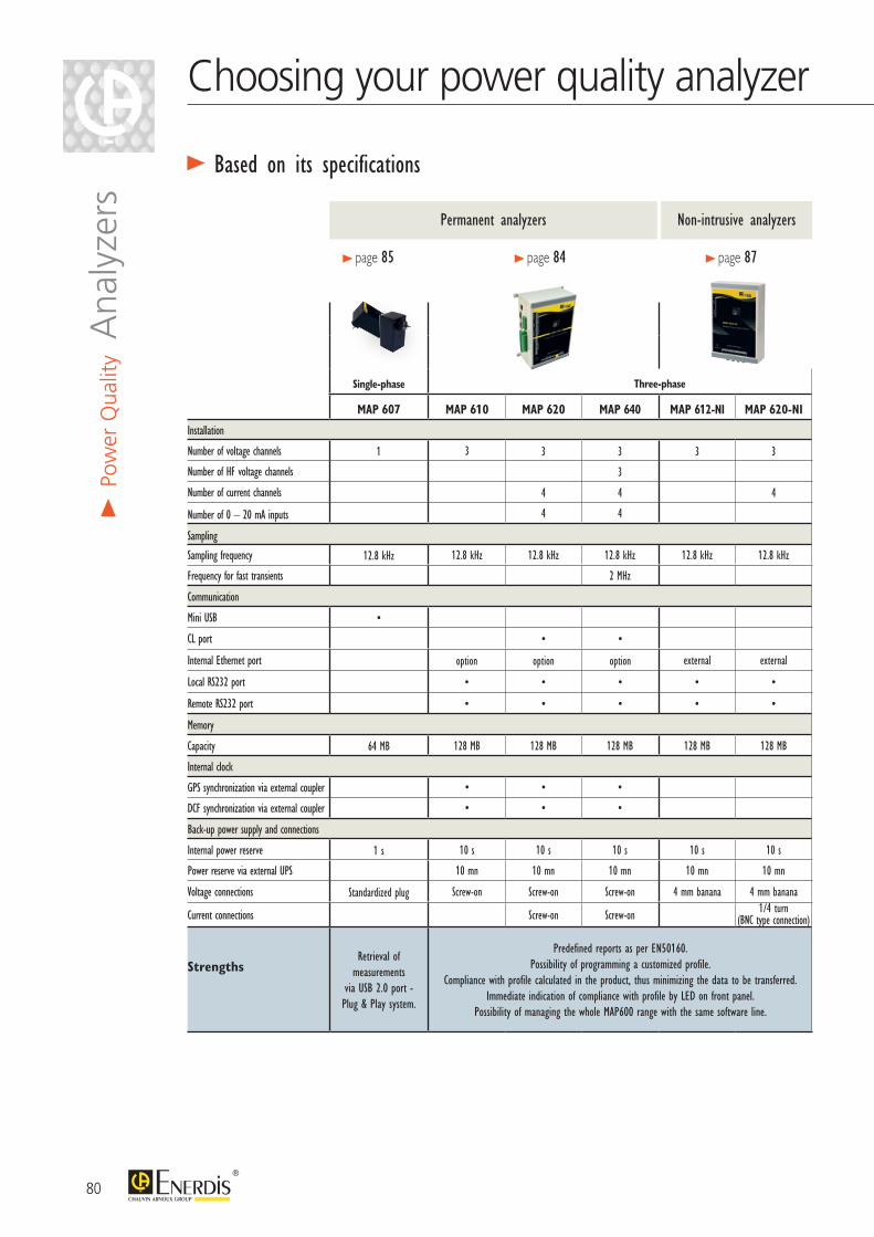
80
Choosing your power quality analyzer
> Based on its specifications
> Po
wer
Qua
lity A
naly
zers
Single-phase
MAP 607 MAP 610 MAP 620 MAP 640 MAP 612-NI MAP 620-NI
Installation
Number of voltage channels 1 3 3 3 3 3
Number of HF voltage channels 3
Number of current channels 4 4 4
Number of 0 – 20 mA inputs 4 4
Sampling
Sampling frequency 12.8 kHz 12.8 kHz 12.8 kHz 12.8 kHz 12.8 kHz 12.8 kHz
Frequency for fast transients 2 MHz
Communication
Mini USB •
CL port • •
Internal Ethernet port option option option external external
Local RS232 port • • • • •
Remote RS232 port • • • • •
Memory
Capacity 64 MB 128 MB 128 MB 128 MB 128 MB 128 MB
Internal clock
GPS synchronization via external coupler • • •
DCF synchronization via external coupler • • •
Back-up power supply and connections
Internal power reserve 1 s 10 s 10 s 10 s 10 s 10 s
Power reserve via external UPS 10 mn 10 mn 10 mn 10 mn 10 mn
Voltage connections Standardized plug Screw-on Screw-on Screw-on 4 mm banana 4 mm banana
Current connections Screw-on Screw-on 1/4 turn (BNC type connection)
StrengthsRetrieval of
measurements via USB 2.0 port - Plug & Play system.
Predefined reports as per EN50160.Possibility of programming a customized profile.
Compliance with profile calculated in the product, thus minimizing the data to be transferred.Immediate indication of compliance with profile by LED on front panel.
Possibility of managing the whole MAP600 range with the same software line.
> page 85 > page 84 > page 87
Permanent analyzers Non-intrusive analyzers
Three-phase
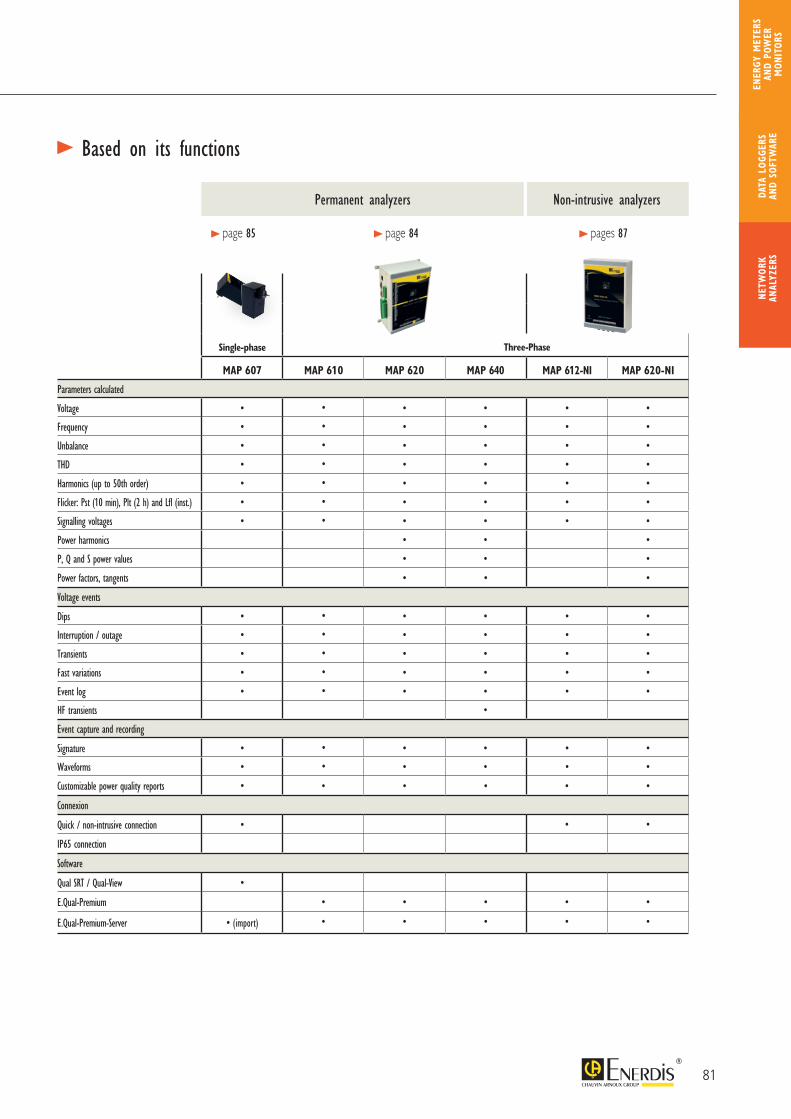
81
> Based on its functions
Single-phase
MAP 607 MAP 610 MAP 620 MAP 640 MAP 612-NI MAP 620-NI
Parameters calculated
Voltage • • • • • •
Frequency • • • • • •
Unbalance • • • • • •
THD • • • • • •
Harmonics (up to 50th order) • • • • • •
Flicker: Pst (10 min), Plt (2 h) and Lfl (inst.) • • • • • •
Signalling voltages • • • • • •
Power harmonics • • •
P, Q and S power values • • •
Power factors, tangents • • •
Voltage events
Dips • • • • • •
Interruption / outage • • • • • •
Transients • • • • • •
Fast variations • • • • • •
Event log • • • • • •
HF transients •
Event capture and recording
Signature • • • • • •
Waveforms • • • • • •
Customizable power quality reports • • • • • •
Connexion
Quick / non-intrusive connection • • •
IP65 connection
Software
Qual SRT / Qual-View •
E.Qual-Premium • • • • •
E.Qual-Premium-Server • (import) • • • • •
> page 85 > page 84 > pages 87
Permanent analyzers Non-intrusive analyzers
Three-Phase
NETW
ORK
ANAL
YZER
SDA
TA L
OGGE
RS
AND
SOFT
WAR
E
ENER
GY M
ETER
S AN
D PO
WER
M
ONIT
ORS
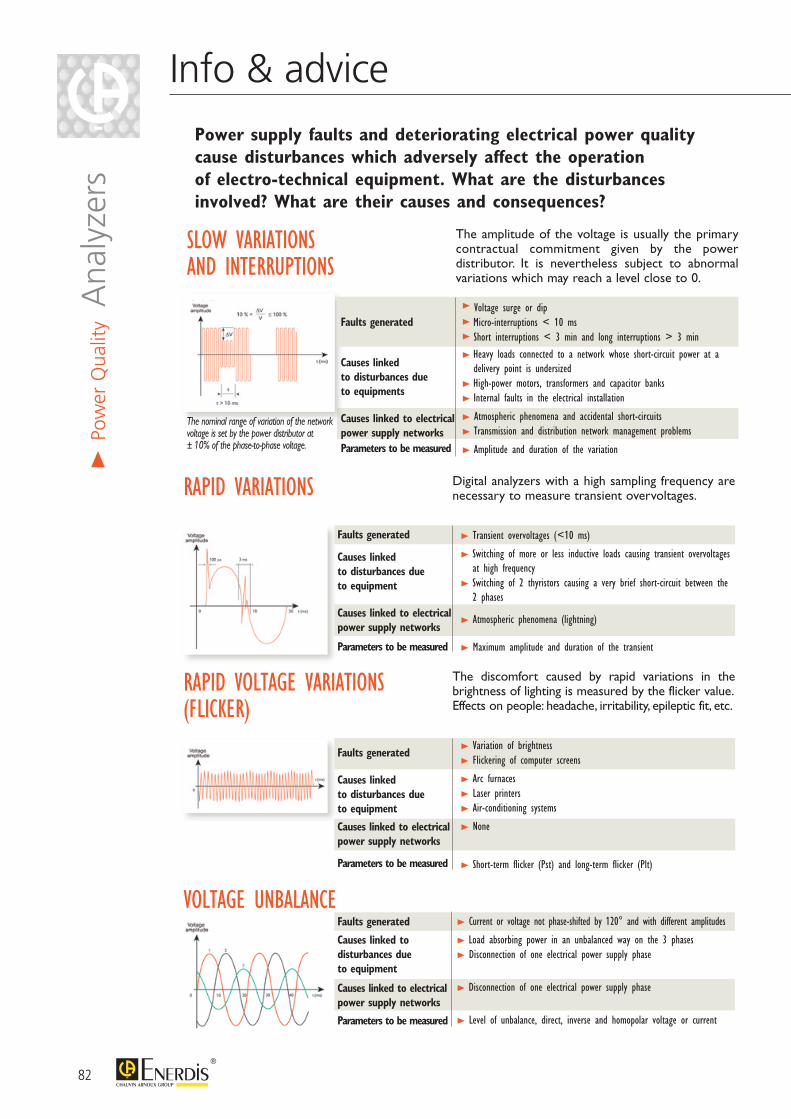
Power supply faults and deteriorating electrical power quality cause disturbances which adversely affect the operation of electro-technical equipment. What are the disturbances involved? What are their causes and consequences?
SLOW VARIATIONS AND INTERRUPTIONS
The amplitude of the voltage is usually the primary contractual commitment given by the power distributor. It is nevertheless subject to abnormal variations which may reach a level close to 0.
>> >
>
> > >>
>
Faults generated
Causes linked to disturbances dueto equipments
Causes linked to electrical power supply networksParameters to be measured
The nominal range of variation of the network voltage is set by the power distributor at ± 10% of the phase-to-phase voltage.
RAPID VARIATIONS Digital analyzers with a high sampling frequency are necessary to measure transient overvoltages.
> Transient overvoltages (<10 ms)
> Switching of more or less inductive loads causing transient overvoltages at high frequency
> Switching of 2 thyristors causing a very brief short-circuit between the 2 phases
> Atmospheric phenomena (lightning)
> Maximum amplitude and duration of the transient
Faults generated
Causes linked to disturbances due to equipment
Causes linked to electrical power supply networks
Parameters to be measured
RAPID VOLTAGE VARIATIONS (FLICKER)
The discomfort caused by rapid variations in the brightness of lighting is measured by the flicker value.Effects on people: headache, irritability, epileptic fit, etc.
> Variation of brightness> Flickering of computer screens
> Arc furnaces > Laser printers > Air-conditioning systems
> None
> Short-term flicker (Pst) and long-term flicker (Plt)
Faults generated
Causes linked to disturbances due to equipment
Causes linked to electrical power supply networks
Parameters to be measured
VOLTAGE UNBALANCE> Current or voltage not phase-shifted by 120° and with different amplitudes
> Load absorbing power in an unbalanced way on the 3 phases> Disconnection of one electrical power supply phase
> Disconnection of one electrical power supply phase
> Level of unbalance, direct, inverse and homopolar voltage or current
Faults generated
Causes linked to disturbances due to equipment
Causes linked to electrical power supply networks
Parameters to be measured
82
Info & advice>
Pow
er Q
ualit
y Ana
lyze
rs
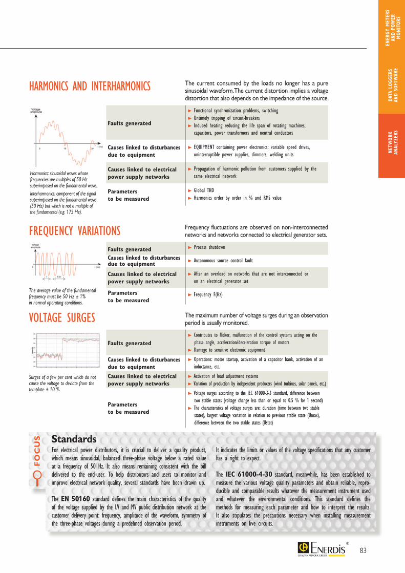
FO
CU
S
For electrical power distributors, it is crucial to deliver a quality product, which means sinusoidal, balanced three-phase voltage below a rated value at a frequency of 50 Hz. It also means remaining consistent with the bill delivered to the end-user. To help distributors and users to monitor and improve electrical network quality, several standards have been drawn up.
The EN 50160 standard defines the main characteristics of the quality of the voltage supplied by the LV and MV public distribution network at the customer delivery point: frequency, amplitude of the waveform, symmetry of the three-phase voltages during a predefined observation period.
It indicates the limits or values of the voltage specifications that any customer has a right to expect.
The IEC 61000-4-30 standard, meanwhile, has been established to measure the various voltage quality parameters and obtain reliable, repro-ducible and comparable results whatever the measurement instrument used and whatever the environmental conditions. This standard defines the methods for measuring each parameter and how to interpret the results. It also stipulates the precautions necessary when installing measurement instruments on live circuits.
Standards
HARMONICS AND INTERHARMONICS
Harmonics: sinusoidal waves whose frequencies are multiples of 50 Hz superimposed on the fundamental wave.Interharmonics: component of the signal superimposed on the fundamental wave (50 Hz) but which is not a multiple of the fundamental (e.g. 175 Hz).
The current consumed by the loads no longer has a pure sinusoidal waveform. The current distortion implies a voltage distortion that also depends on the impedance of the source.
> Functional synchronization problems, switching> Untimely tripping of circuit-breakers> Induced heating reducing the life span of rotating machines,
capacitors, power transformers and neutral conductors
> EQUIPMENT containing power electronics: variable speed drives, uninterruptible power supplies, dimmers, welding units
> Propagation of harmonic pollution from customers supplied by the same electrical network
> Global THD> Harmonics order by order in % and RMS value
Faults generated
Causes linked to disturbances due to equipment
Causes linked to electrical power supply networks
Parameters to be measured
The maximum number of voltage surges during an observation period is usually monitored.
> Contributes to flicker, malfunction of the control systems acting on the phase angle, acceleration/deceleration torque of motors> Damage to sensitive electronic equipment
> Operations: motor startup, activation of a capacitor bank, activation of an inductance, etc.
> Activation of load adjustment systems> Variation of production by independent producers (wind turbines, solar panels, etc.)
> Voltage surges according to the IEC 61000-3-3 standard, difference between two stable states (voltage change less than or equal to 0.5 % for 1 second)> The characteristics of voltage surges are: duration (time between two stable states), largest voltage variation in relation to previous stable state (Umax), difference between the two stable states (Ustat)
Faults generated
Causes linked to disturbances due to equipment
Causes linked to electrical power supply networks
Parameters to be measured
FREQUENCY VARIATIONS
The average value of the fundamental frequency must be 50 Hz ± 1% in normal operating conditions.
Frequency fluctuations are observed on non-interconnected networks and networks connected to electrical generator sets.
> Process shutdown
> Autonomous source control fault
> After an overload on networks that are not interconnected or on an electrical generator set
> Frequency F(Hz)
Faults generatedCauses linked to disturbances due to equipment
Causes linked to electrical power supply networks
Parameters to be measured
VOLTAGE SURGES
Surges of a few per cent which do not cause the voltage to deviate from the template ± 10 %.
83
NETW
ORK
ANAL
YZER
SDA
TA L
OGGE
RS
AND
SOFT
WAR
E
ENER
GY M
ETER
S AN
D PO
WER
M
ONIT
ORS

The products in the MAP range, mounted on a platen or on the cabinet backplate, measure all the parameters of HV/MV/LV electrical networks: RMS voltage, frequency, THD, level of unbalance, positive/negative/zero sequence voltage, flicker, harmonics up to the 50th order, interharmonics up to the 50th group. For products with current channels: RMS current, THDI, active, reactive and apparent power, cos ϕ, power factor, power values of harmonics, energy values (calculated by the software).
The products in the MAP range record and, via the associated software, provide detailed, comprehensive and continuous analysis of the quality of the electricity supplied according to the applicable standards, particularly EN 50160: voltage variations (voltage dips, swells and outages), rapid variations (transient overvoltages), flicker or rapid voltage fluctuations…
Various communication modes are available for remote retrieval of the data and detailed analysis of all the parameters recorded. On some models, additional 20 mA analogue inputs can be used to:• monitor physical parameters from a 20 mA transducer• monitor statuses such as circuit-breaker contacts and protection relays via
suitable couplers• trigger waveform capture by a digital channel via a digital input/20 mA signal coupler• check the equipment transmitting binary signals
> General specifications
COMPLIANT with the EN 61000-4-30
standard, Class A
DETECTION of the fault LOCATION DIRECTION (upstream/downstream)
for products with current channels
ANALYSIS OF TRANSIENTS with a high, variable sampling frequency
MEASUREMENT OF HARMONICS (up to 50th order) and INTERHARMONICS (up to 50th group)
FLICKER MEASUREMENT: Ifl, Pst, Plt
PROCESSING of the data according to
the EN 50160 standard
PRODUCT ADVANTAGES
Status LED: phase order and template overrun
Communication port: local, modem, integrated Ethernet, multi-point
Communication couplers: local, modem, Ethernet
84
MAP RangeHV / MV / LV electrical power quality analyzers – Class A
> Po
wer
Qua
lity A
naly
zers

MAP 607Single-phase analyzer – Class A 2 voltage channels: phase/neutral and phase/neutral-earth Plug & play: no driver required USB 2.0 communication port Configuration for voltage dips, overvoltages and
transient disturbances Class A according to IEC 61000-4-30 Measurement of all the power quality parameters according
to the predefined standard (EN 50160, etc.) Direct indication on the product:
Green LED: parameters OK Red LED: parameters outside profile
InputsVoltage input (Phase-Neutral) 0-300 V RMS Standard measurement (Class A) 1Voltage input (Phase/Neutral-Earth) 0-300 V RMS, 700 Vpk 1Power supplyPower supply range Power supply via voltage input YesInternal back-up YesCompliance with standardsSliding reference YesIEC 61000-4-30, Class A < 0.1% Reference equipment YesIEC 61000-4-7 Measurement of harmonics YesIEC 61000-4-15 Flicker measurement YesEN 50 160 (European Norm) Calculated in the unit YesPQDIF format OptionHardwareMemory Circular Flash Memory (NAND) 64 MBSampling rate 12.8 kHz (x 2)Accuracy Class A < 0.1%Resolution 16 bitsInput impedance – Input voltage 10 MΩAnti-aliasing filter YesBandwidth 3.5 kHzPLL Synchronization YesCommunication
USB port 2.0 (full-speed) For PC connection, detected automaticallyDriver not required Yes
Measurement specificationsAll power quality parameters are measured and stored
Voltage (avg/min/max), Frequency, THD, Harmon-ics (up to 50th order), Flicker (Lfl, Pst, Plt) Yes
Analysis of rapid disturbances Dips/swells (RMS 1/2 cycle), transients YesWaveform capture Programmable pre-time and post-time Max. duration 200 cyclesMechanical specificationsHousing For 230 V socket Humidity: 10% - 85% without condensationDimensions (L x H x D) 120 x 65 x 65 mmWeight 0.3 kg Safety: EN 61 010-1Operating temperature -10°C +55°C EMC: EN 58 081-1,2; EN 50 082-1,2
Management and analysis software Qual-SRT: configuration and
real-time display Qual-view: analysis and reports
T O O R D E R
Reference Package includes: MAP607-P - MAP607- mini USB cable- Qual-view and Qual-SRT software- carrying case
85
NETW
ORK
ANAL
YZER
SDA
TA L
OGGE
RS
AND
SOFT
WAR
E
ENER
GY M
ETER
S AN
D PO
WER
M
ONIT
ORS
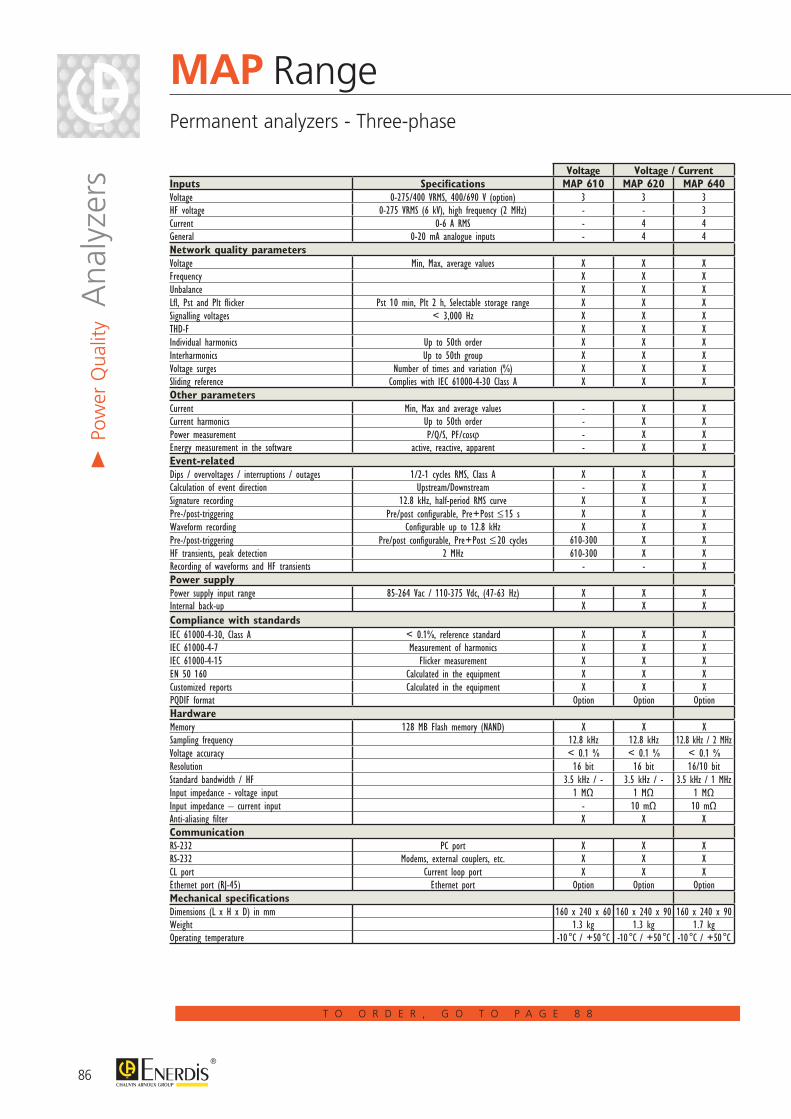
86
MAP RangePermanent analyzers - Three-phase
> Po
wer
Qua
lity A
naly
zers
T O O R D E R , G O T O P A G E 8 8
Voltage Voltage / CurrentInputs Specifications MAP 610 MAP 620 MAP 640Voltage 0-275/400 VRMS, 400/690 V (option) 3 3 3HF voltage 0-275 VRMS (6 kV), high frequency (2 MHz) - - 3 Current 0-6 A RMS - 4 4General 0-20 mA analogue inputs - 4 4Network quality parametersVoltage Min, Max, average values X X XFrequency X X XUnbalance X X XLfl, Pst and Plt flicker Pst 10 min, Plt 2 h, Selectable storage range X X XSignalling voltages < 3,000 Hz X X XTHD-F X X XIndividual harmonics Up to 50th order X X XInterharmonics Up to 50th group X X XVoltage surges Number of times and variation (%) X X XSliding reference Complies with IEC 61000-4-30 Class A X X XOther parametersCurrent Min, Max and average values - X XCurrent harmonics Up to 50th order - X XPower measurement P/Q/S, PF/cosϕ - X XEnergy measurement in the software active, reactive, apparent - X XEvent-relatedDips / overvoltages / interruptions / outages 1/2-1 cycles RMS, Class A X X XCalculation of event direction Upstream/Downstream - X XSignature recording 12.8 kHz, half-period RMS curve X X XPre-/post-triggering Pre/post configurable, Pre+Post ≤ 15 s X X XWaveform recording Configurable up to 12.8 kHz X X XPre-/post-triggering Pre/post configurable, Pre+Post ≤ 20 cycles 610-300 X XHF transients, peak detection 2 MHz 610-300 X XRecording of waveforms and HF transients - - XPower supplyPower supply input range 85-264 Vac / 110-375 Vdc, (47-63 Hz) X X XInternal back-up X X XCompliance with standardsIEC 61000-4-30, Class A < 0.1%, reference standard X X XIEC 61000-4-7 Measurement of harmonics X X XIEC 61000-4-15 Flicker measurement X X XEN 50 160 Calculated in the equipment X X XCustomized reports Calculated in the equipment X X XPQDIF format Option Option OptionHardwareMemory 128 MB Flash memory (NAND) X X XSampling frequency 12.8 kHz 12.8 kHz 12.8 kHz / 2 MHzVoltage accuracy < 0.1 % < 0.1 % < 0.1 %Resolution 16 bit 16 bit 16/10 bitStandard bandwidth / HF 3.5 kHz / - 3.5 kHz / - 3.5 kHz / 1 MHzInput impedance - voltage input 1 MΩ 1 MΩ 1 MΩInput impedance – current input - 10 mΩ 10 mΩAnti-aliasing filter X X XCommunicationRS-232 PC port X X XRS-232 Modems, external couplers, etc. X X XCL port Current loop port X X XEthernet port (RJ-45) Ethernet port Option Option OptionMechanical specificationsDimensions (L x H x D) in mm 160 x 240 x 60 160 x 240 x 90 160 x 240 x 90Weight 1.3 kg 1.3 kg 1.7 kgOperating temperature -10 °C / +50 °C -10 °C / +50 °C -10 °C / +50 °C
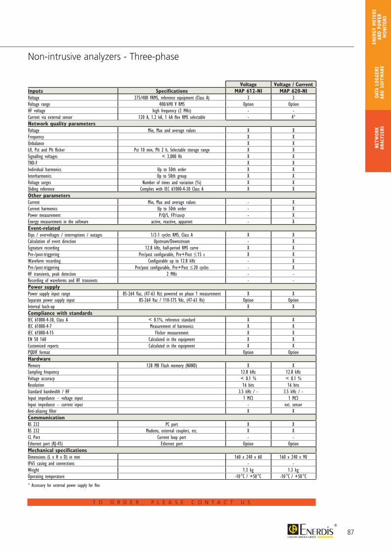
87
Non-intrusive analyzers - Three-phase
T O O R D E R , P L E A S E C O N T A C T U S
Voltage Voltage / CurrentInputs Specifications MAP 612-NI MAP 620-NIVoltage 275/400 VRMS, reference equipment (Class A) 3 3Voltage range 400/690 V RMS Option OptionHF voltage high frequency (2 MHz) - -Current via external sensor 120 A, 1.2 kA, 1 kA flex RMS selectable - 4*Network quality parametersVoltage Min, Max and average values X XFrequency X XUnbalance X XLfl, Pst and Plt flicker Pst 10 min, Plt 2 h, Selectable storage range X XSignalling voltages < 3,000 Hz X XTHD-F X XIndividual harmonics Up to 50th order X XInterharmonics Up to 50th group X XVoltage surges Number of times and variation (%) X XSliding reference Complies with IEC 61000-4-30 Class A X XOther parametersCurrent Min, Max and average values - XCurrent harmonics Up to 50th order - XPower measurement P/Q/S, FP/cosϕ - XEnergy measurement in the software active, reactive, apparent - XEvent-relatedDips / overvoltages / interruptions / outages 1/2-1 cycles RMS, Class A X XCalculation of event direction Upstream/Downstream - XSignature recording 12.8 kHz, half-period RMS curve X XPre-/post-triggering Pre/post configurable, Pre+Post ≤ 15 s X XWaveform recording Configurable up to 12.8 kHz - XPre-/post-triggering Pre/post configurable, Pre+Post ≤ 20 cycles - XHF transients, peak detection 2 MHz - -Recording of waveforms and HF transients - -Power supplyPower supply input range 85-264 Vac, (47-63 Hz) powered on phase 1 measurement X XSeparate power supply input 85-264 Vac / 110-375 Vdc, (47-63 Hz) Option OptionInternal back-up X XCompliance with standardsIEC 61000-4-30, Class A < 0.1%, reference standard X XIEC 61000-4-7 Measurement of harmonics X XIEC 61000-4-15 Flicker measurement X XEN 50 160 Calculated in the equipment X XCustomized reports Calculated in the equipment X XPQDIF format Option OptionHardwareMemory 128 MB Flash memory (NAND) X XSampling frequency 12.8 kHz 12.8 kHzVoltage accuracy < 0.1 % < 0.1 %Resolution 16 bits 16 bitsStandard bandwidth / HF 3.5 kHz / - 3.5 kHz / -Input impedance – voltage input 1 MΩ 1 MΩInput impedance – current input - ext. sensorAnti-aliasing filter X XCommunicationRS 232 PC port X XRS 232 Modems, external couplers, etc. X XCL Port Current loop port - -Ethernet port (RJ-45) Ethernet port Option OptionMechanical specificationsDimensions (L x H x D) in mm 160 x 240 x 60 160 x 240 x 90IP65 casing and connections - -Weight 1.3 kg 1.3 kgOperating temperature -10 °C / +50 °C -10 °C / +50 °C
* Accessory for external power supply for flex
NETW
ORK
ANAL
YZER
SDA
TA L
OGGE
RS
AND
SOFT
WAR
E
ENER
GY M
ETER
S AN
D PO
WER
M
ONIT
ORS

> EnvironmentOperating temperature: -10°C to + 50°CRelative humidity:10% - 85%, without condensationInstallation category:Category III, 600 V (300 V for the MAP607)Pollution level: 2
> Compliance with standardsMeasurements:- EN 61000-4-30: Voltage quality measurement method
(Class A RMS values)- EN 61000-4-7: General guide to harmonic and
interharmonic measurements- EN 61000-4-15: Test and measurement technique:
flickermeterSafety (Low Voltage Directive):- EN 61010-1: Safety rules for electrical equipment
for measurement, testing and laboratory use- EN 60950: Safety of data processing equipmentCommunication:- Protocol compatible with the associated Qual-SRT,
E.Qual-Premium and E.Qual-Premium Server software, TCP/IP encapsulation on internal Ethernet port (option)
Electromagnetic compatibility: - EN 61326-1: Instructions concerning EMC for electrical
measurement, control and laboratory equipment including:
- EN 61000-4-2: Electrostatic discharge Level 3 (Air 8 kV / Contact 4 kV)
- EN 61000-4-3: Immunity to radiated electrostatic fields – Level 3 (10 V/m)
- EN 61000-4-4: Fast electrical transients – Level 4 (2 kV)- EN 61000-4-5: Immunity to voltage surges – Level 4
(common mode 2 kV, differential mode 1 kV)- EN 61000-4-6: Immunity to conducted disturbances –
Level 3 (3 Vrms)- EN 61000-4-8: Level 4 (30 A/m)- EN 61000-4-11: Level 0 (duration 0.5 period – voltage dip
and short interruption 100% U)- EN 61000-4-12: Level 3 (common mode 2.5 kV / diff. mode
1.0 kV)- CISPR 16-2-1, CISPR 16-2-3, EN55011 (EN5022 required
by the generic standard EN 61326)
> Mechanical specificationsWeight:- 1.3 kg (MAP 610, MAP612-NI, MAP 620 and MAP640)- Mechanical shock test: EN60068-2-27: table 1: 30 g/18 m sec
Connection:- 4 mm² cable for U and I- 2.5 mm² cable for inputs/outputs
MAP Range Self-powered analyzer – Measurement in pole-mounted boxes
Output via leakproofconnectors on the underside of the box
MAP 620-NI in its pole-mount box withthe voltage coil and the current-sensor torch
T O O R D E R , P L E A S E C O N T A C T U S
88
> Po
wer
Qua
lity A
naly
zers
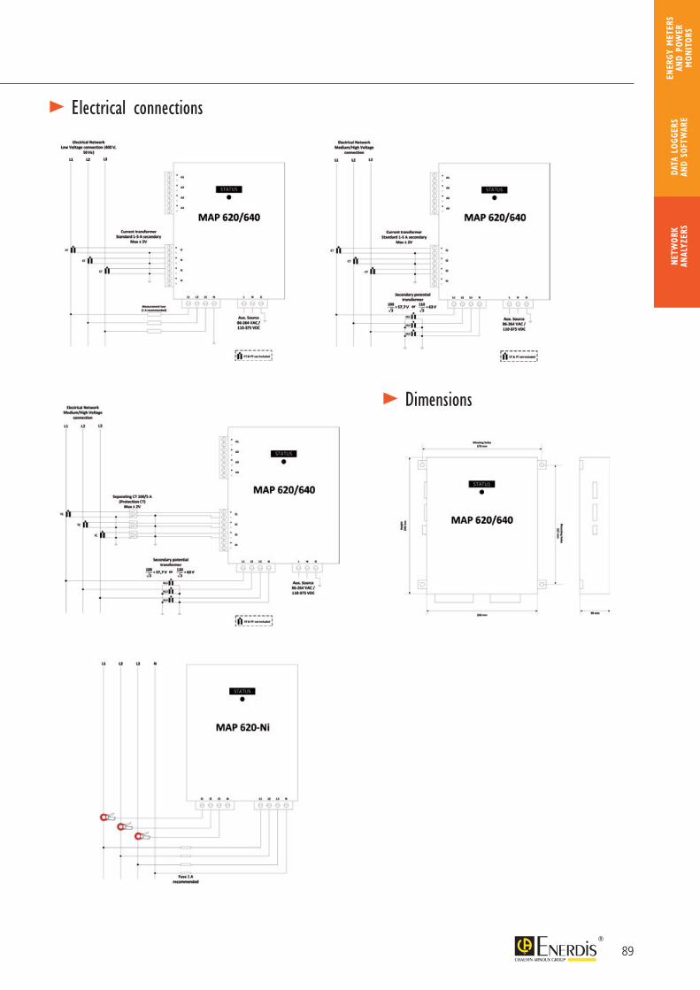
> Electrical connections
> Dimensions
89
NETW
ORK
ANAL
YZER
SDA
TA L
OGGE
RS
AND
SOFT
WAR
E
ENER
GY M
ETER
S AN
D PO
WER
M
ONIT
ORS
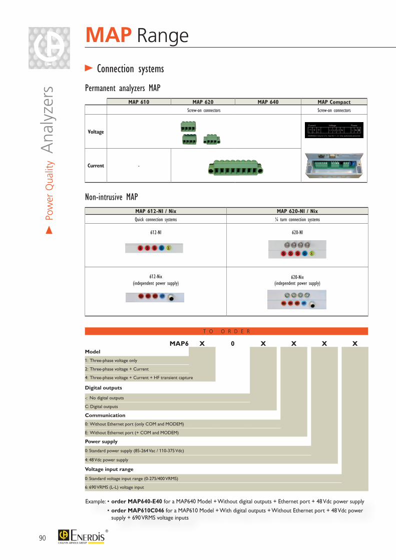
90
MAP Range
MAP 610 MAP 620 MAP 640 MAP CompactScrew-on connectors Screw-on connectors
Voltage
Current -
> Connection systems
Permanent analyzers MAP
MAP 612-NI / Nix MAP 620-NI / NixQuick connection systems ¼ turn connection systems
612-NI 620-NI
612-Nix (independent power supply)
620-Nix (independent power supply)
Non-intrusive MAP
> Po
wer
Qua
lity A
naly
zers
Example: • order MAP640-E40 for a MAP640 Model + Without digital outputs + Ethernet port + 48 Vdc power supply
• order MAP610C046 for a MAP610 Model + With digital outputs + Without Ethernet port + 48 Vdc power supply + 690 VRMS voltage inputs
T O O R D E R
MAP6 X 0 X X X XModel
1: Three-phase voltage only
2: Three-phase voltage + Current
4: Three-phase voltage + Current + HF transient capture
Digital outputs
-: No digital outputs
C: Digital outputs
Communication
0: Without Ethernet port (only COM and MODEM)
E: Without Ethernet port (+ COM and MODEM)
Power supply
0: Standard power supply (85-264 Vac / 110-375 Vdc)
4: 48 Vdc power supply
Voltage input range
0: Standard voltage input range (0-275/400 VRMS)
6: 690 VRMS (L-L) voltage input
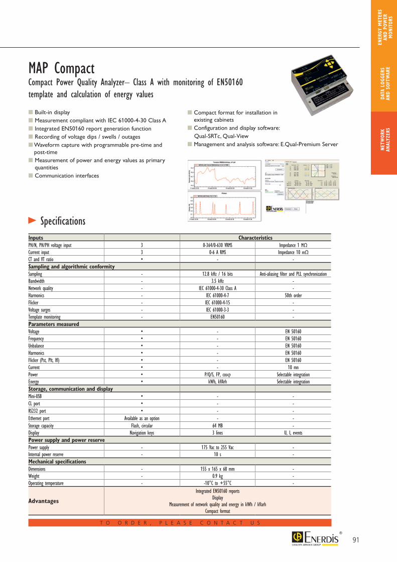
91
MAP CompactCompact Power Quality Analyzer– Class A with monitoring of EN50160 template and calculation of energy values
Built-in display Measurement compliant with IEC 61000-4-30 Class A Integrated EN50160 report generation function Recording of voltage dips / swells / outages Waveform capture with programmable pre-time and
post-time Measurement of power and energy values as primary
quantities Communication interfaces
Inputs CharacteristicsPH/N, PH/PH voltage input 3 0-364/0-630 VRMS Impedance 1 MΩCurrent input 3 0-6 A RMS Impedance 10 mΩCT and VT ratio • - -Sampling and algorithmic conformitySampling - 12.8 kHz / 16 bits Anti-aliasing filter and PLL synchronizationBandwidth - 3.5 kHz -Network quality - IEC 61000-4-30 Class A -Harmonics - IEC 61000-4-7 50th orderFlicker - IEC 61000-4-15 -Voltage surges - IEC 61000-3-3 -Template monitoring - EN50160 -Parameters measuredVoltage • - EN 50160Frequency • - EN 50160Unbalance • - EN 50160Harmonics • - EN 50160Flicker (Pst, Plt, Ifl) • - EN 50160Current • - 10 mnPower • P/Q/S, FP, cosϕ Selectable integrationEnergy • kWh, kVArh Selectable integrationStorage, communication and displayMini-USB • - -CL port • - -RS232 port • - -Ethernet port Available as an option - -Storage capacity Flash, circular 64 MB -Display Navigation keys 3 lines U, I, eventsPower supply and power reservePower supply - 175 Vac to 255 Vac -Internal power reserve - 10 s -Mechanical specificationsDimensions - 155 x 165 x 68 mm -Weight - 0.9 kg -Operating temperature - -10°C to +55°C -
Advantages
Integrated EN50160 reportsDisplay
Measurement of network quality and energy in kWh / kVarhCompact format
T O O R D E R , P L E A S E C O N T A C T U S
> Specifications
Compact format for installation in existing cabinets
Configuration and display software: Qual-SRTc, Qual-View Management and analysis software: E.Qual-Premium Server
NETW
ORK
ANAL
YZER
SDA
TA L
OGGE
RS
AND
SOFT
WAR
E
ENER
GY M
ETER
S AN
D PO
WER
M
ONIT
ORS
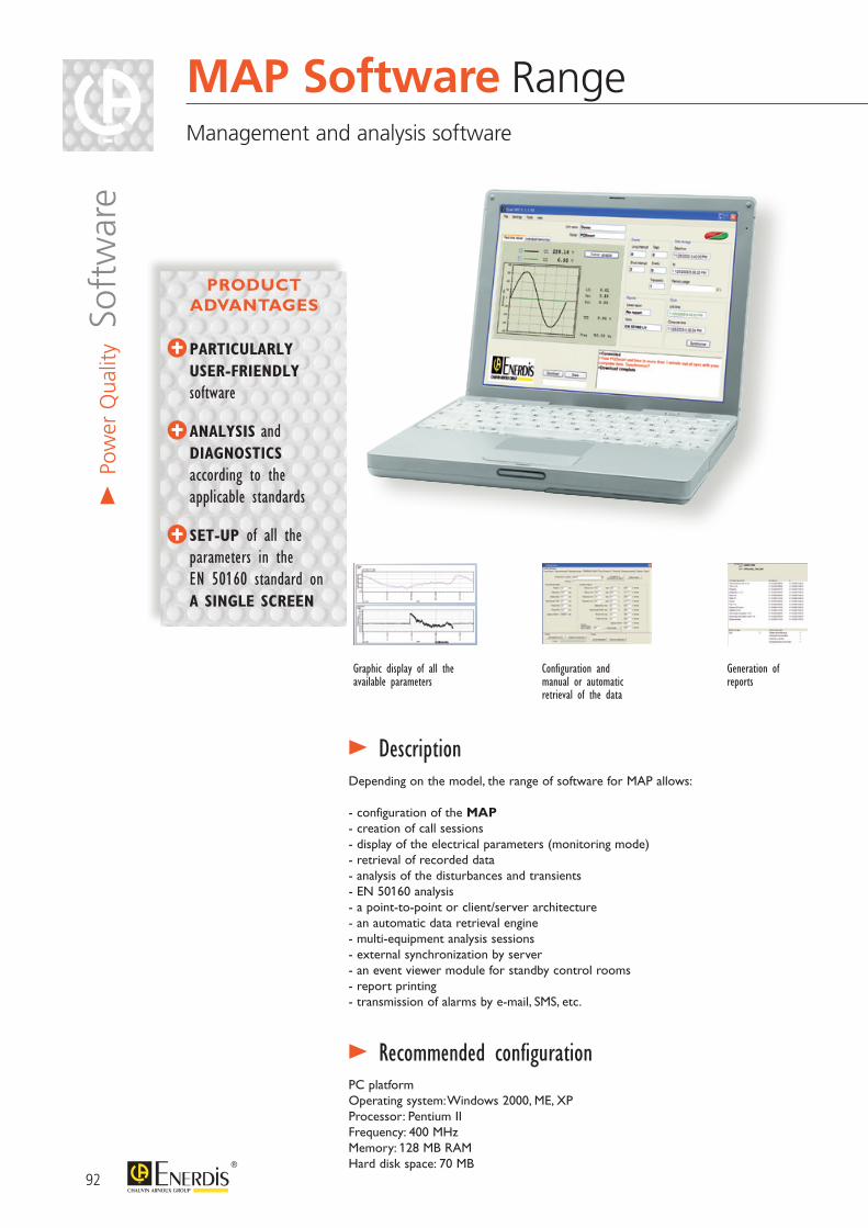
Depending on the model, the range of software for MAP allows:
- configuration of the MAP- creation of call sessions- display of the electrical parameters (monitoring mode)- retrieval of recorded data- analysis of the disturbances and transients- EN 50160 analysis- a point-to-point or client/server architecture- an automatic data retrieval engine- multi-equipment analysis sessions- external synchronization by server- an event viewer module for standby control rooms- report printing- transmission of alarms by e-mail, SMS, etc.
> Description
PC platformOperating system: Windows 2000, ME, XPProcessor: Pentium IIFrequency: 400 MHzMemory: 128 MB RAMHard disk space: 70 MB
> Recommended configuration
PARTICULARLY USER-FRIENDLY software
ANALYSIS and DIAGNOSTICS according to the
applicable standards
SET-UP of all the parameters in the EN 50160 standard on A SINGLE SCREEN
PRODUCT ADVANTAGES
Graphic display of all the available parameters
Configuration and manual or automatic retrieval of the data
Generation of reports
92
MAP Software RangeManagement and analysis software
> Po
wer
Qua
lity S
oftw
are
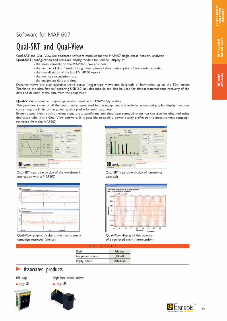
Qual-SRT and Qual-View
MAP range
> page 84Single-phase network analyzer
> page 85
T O O R D E R
Model ReferenceConfiguration software QUAL-SRTDisplay software QUAL-VIEW
Qual-SRT and Qual-View are dedicated software modules for the MAP607 single-phase network analyzer.Qual-SRT: configuration and real-time display module for “online” display of:
- the measurements on the MAP607’s two channels - the number of dips / swells / long interruptions / short interruptions / transients recorded - the overall status of the last EN 50160 report - the memory occupation rate - the equipment date and time
Dynamic views are also available: trend curve (logger-type view) and bargraph of harmonics up to the 50th order. Thanks to the ultra-fast self-declaring USB 2.0 link, this module can also be used for almost instantaneous recovery of the data and deletion of the data from the equipment.
Qual-View: analysis and report generation module for MAP607-type data.This provides a view of all the trend curves generated by the equipment and includes zoom and graphic display functions concerning the limits of the power quality profile for each parameter.Event-related views such as event signatures, waveforms and time/date-stamped event log can also be obtained using dedicated tabs in the Qual-View software. It is possible to apply a power quality profile to the measurement campaign retrieved from the MAP607.
Qual-SRT: real-time display of the waveform in connection with a MAP607
Qual-SRT: real-time display of harmonics bargraph
Qual-View: graphic display of the measurement campaign retrieved (trends)
Qual-View: display of the waveform of a retrieved event (interruption)
93
Software for MAP 607
> Associated products
NETW
ORK
ANAL
YZER
SDA
TA L
OGGE
RS
AND
SOFT
WAR
E
ENER
GY M
ETER
S AN
D PO
WER
M
ONIT
ORS
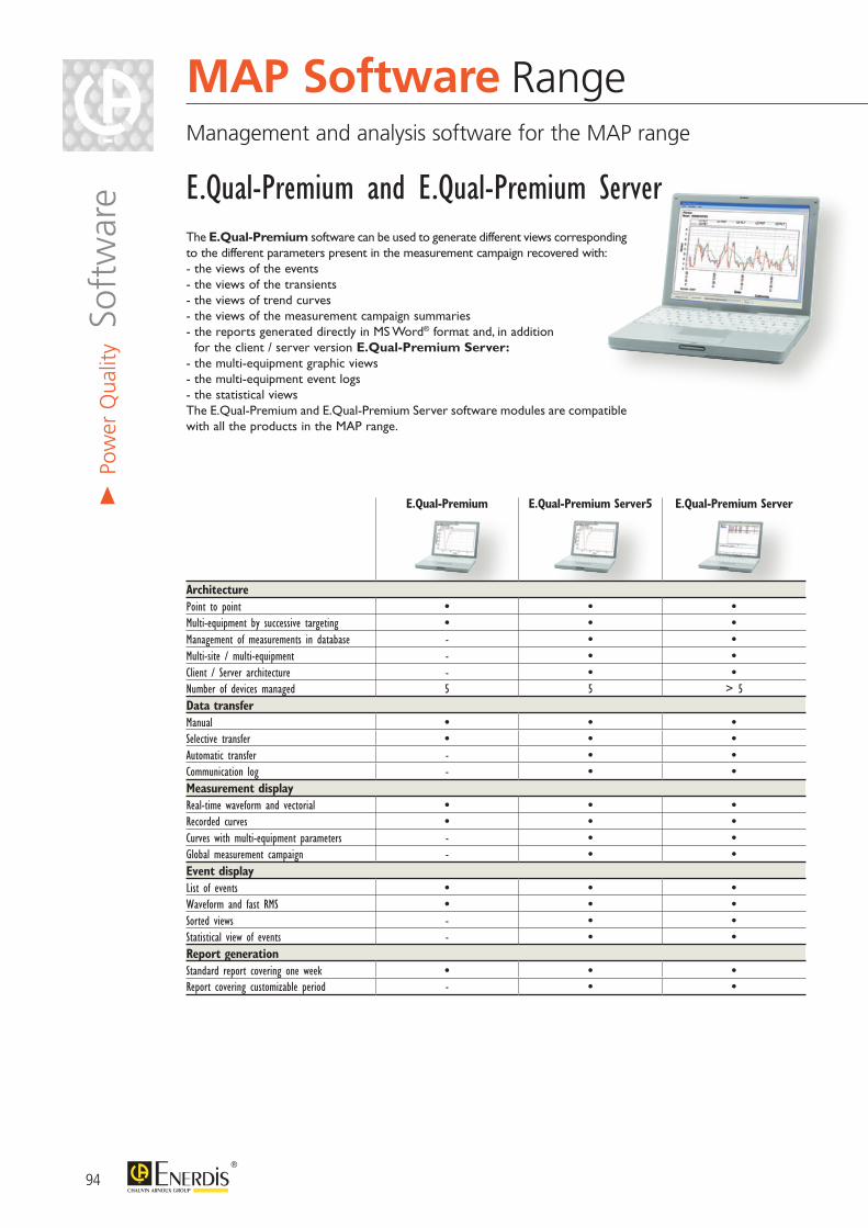
The E.Qual-Premium software can be used to generate different views corresponding to the different parameters present in the measurement campaign recovered with:- the views of the events- the views of the transients- the views of trend curves- the views of the measurement campaign summaries- the reports generated directly in MS Word® format and, in addition
for the client / server version E.Qual-Premium Server:- the multi-equipment graphic views- the multi-equipment event logs- the statistical viewsThe E.Qual-Premium and E.Qual-Premium Server software modules are compatible with all the products in the MAP range.
E.Qual-Premium E.Qual-Premium Server5 E.Qual-Premium Server
ArchitecturePoint to point • • •Multi-equipment by successive targeting • • •Management of measurements in database - • •Multi-site / multi-equipment - • •Client / Server architecture - • •Number of devices managed 5 5 > 5Data transferManual • • •Selective transfer • • •Automatic transfer - • •Communication log - • •Measurement displayReal-time waveform and vectorial • • •Recorded curves • • •Curves with multi-equipment parameters - • •Global measurement campaign - • •Event displayList of events • • •Waveform and fast RMS • • •Sorted views - • •Statistical view of events - • •Report generationStandard report covering one week • • •Report covering customizable period - • •
E.Qual-Premium and E.Qual-Premium Server
94
> Po
wer
Qua
lity S
oftw
are
MAP Software RangeManagement and analysis software for the MAP range
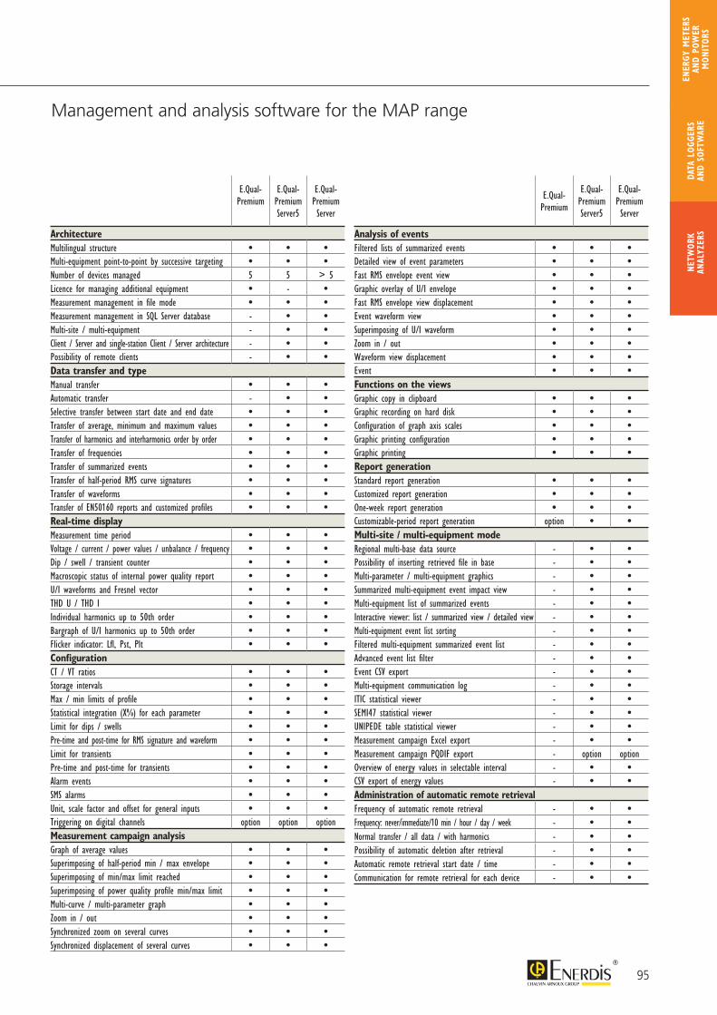
E.Qual- Premium
E.Qual-Premium Server5
E.Qual-Premium Server
ArchitectureMultilingual structure • • •Multi-equipment point-to-point by successive targeting • • •Number of devices managed 5 5 > 5Licence for managing additional equipment • - •Measurement management in file mode • • •Measurement management in SQL Server database - • •Multi-site / multi-equipment - • •Client / Server and single-station Client / Server architecture - • •Possibility of remote clients - • •Data transfer and typeManual transfer • • •Automatic transfer - • •Selective transfer between start date and end date • • •Transfer of average, minimum and maximum values • • •Transfer of harmonics and interharmonics order by order • • •Transfer of frequencies • • •Transfer of summarized events • • •Transfer of half-period RMS curve signatures • • •Transfer of waveforms • • •Transfer of EN50160 reports and customized profiles • • •Real-time displayMeasurement time period • • •Voltage / current / power values / unbalance / frequency • • •Dip / swell / transient counter • • •Macroscopic status of internal power quality report • • •U/I waveforms and Fresnel vector • • •THD U / THD I • • •Individual harmonics up to 50th order • • •Bargraph of U/I harmonics up to 50th order • • •Flicker indicator: Lfl, Pst, Plt • • •ConfigurationCT / VT ratios • • •Storage intervals • • •Max / min limits of profile • • •Statistical integration (X%) for each parameter • • •Limit for dips / swells • • •Pre-time and post-time for RMS signature and waveform • • •Limit for transients • • •Pre-time and post-time for transients • • •Alarm events • • •SMS alarms • • •Unit, scale factor and offset for general inputs • • •Triggering on digital channels option option optionMeasurement campaign analysisGraph of average values • • •Superimposing of half-period min / max envelope • • •Superimposing of min/max limit reached • • •Superimposing of power quality profile min/max limit • • •Multi-curve / multi-parameter graph • • •Zoom in / out • • •Synchronized zoom on several curves • • •Synchronized displacement of several curves • • •
E.Qual- Premium
E.Qual-Premium Server5
E.Qual-Premium Server
Analysis of eventsFiltered lists of summarized events • • •Detailed view of event parameters • • •Fast RMS envelope event view • • •Graphic overlay of U/I envelope • • •Fast RMS envelope view displacement • • •Event waveform view • • •Superimposing of U/I waveform • • •Zoom in / out • • •Waveform view displacement • • •Event • • •Functions on the viewsGraphic copy in clipboard • • •Graphic recording on hard disk • • •Configuration of graph axis scales • • •Graphic printing configuration • • •Graphic printing • • •Report generationStandard report generation • • •Customized report generation • • •One-week report generation • • •Customizable-period report generation option • •Multi-site / multi-equipment modeRegional multi-base data source - • •Possibility of inserting retrieved file in base - • •Multi-parameter / multi-equipment graphics - • •Summarized multi-equipment event impact view - • •Multi-equipment list of summarized events - • •Interactive viewer: list / summarized view / detailed view - • •Multi-equipment event list sorting - • •Filtered multi-equipment summarized event list - • •Advanced event list filter - • •Event CSV export - • •Multi-equipment communication log - • •ITIC statistical viewer - • •SEMI47 statistical viewer - • •UNIPEDE table statistical viewer - • •Measurement campaign Excel export - • •Measurement campaign PQDIF export - option optionOverview of energy values in selectable interval - • •CSV export of energy values - • •Administration of automatic remote retrievalFrequency of automatic remote retrieval - • •Frequency: never/immediate/10 min / hour / day / week - • •Normal transfer / all data / with harmonics - • •Possibility of automatic deletion after retrieval - • •Automatic remote retrieval start date / time - • •Communication for remote retrieval for each device - • •
95
Management and analysis software for the MAP range
NETW
ORK
ANAL
YZER
SDA
TA L
OGGE
RS
AND
SOFT
WAR
E
ENER
GY M
ETER
S AN
D PO
WER
M
ONIT
ORS
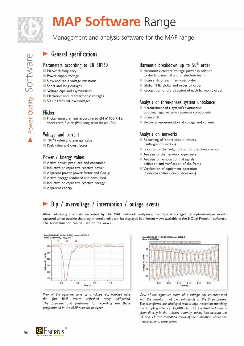
View of the signature curve of a voltage dip superimposed with the waveforms of the real signals on the three phases. The waveforms are displayed with a high resolution matching the sampling rate, i.e. 12,800 Hz. The event-related view is given directly in the primary quantity, taking into account the CT and VT transformation ratios of the substation where the measurements were taken.
> General specifications
After retrieving the data recorded by the MAP network analyzers, the dip/overvoltage/interruption/outage events captured when outside the programmed profile can be displayed in different views available in the E.Qual-Premium software. The zoom function can be used on the views.
> Dip / overvoltage / interruption / outage events
View of the signature curve of a voltage dip, obtained using the fast RMS values refreshed every half-period. The pre-time and post-time for recording are those programmed in the MAP network analyzer.
Parameters according to EN 50160 Network frequency Power supply voltage Slow and rapid voltage variations Short and long outages Voltage dips and asymmetries Harmonic and interharmonic voltages 50 Hz transient overvoltages
Flicker Flicker measurement according to EN 61000-4-15:
short-term flicker (Pst), long-term flicker (Plt)
Voltage and current TRMS value and average value Peak value and crest factor
Power / Energy values Active power produced and consumed Inductive or capacitive reactive power Apparent power, power factor and Cos ϕ Active energy produced and consumed Inductive or capacitive reactive energy Apparent energy
Harmonic breakdown up to 50th order Harmonics: current, voltage, power in relation
to the fundamental and in absolute terms Phase shift of each harmonic order Global THD global and order by order Recognition of the direction of each harmonic order
Analysis of three-phase system unbalance Measurement of a system’s symmetry:
positive, negative, zero sequence components Phase shift Vectorial representation of voltage and current
Analysis on networks Recording of “short-circuit” events
(faultograph function) Location of the fault, duration of the phenomenon Analysis of the network impedance Analysis of remote control signals:
definition and verification of the frame Verification of equipment operation
(capacitors, filters, circuit-breakers)
96
MAP Software RangeManagement and analysis software for the MAP range
> Po
wer
Qua
lity S
oftw
are
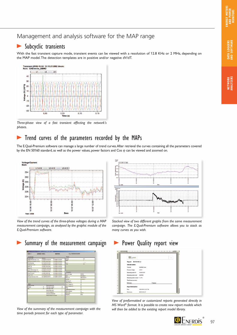
With the fast transient capture mode, transient events can be viewed with a resolution of 12.8 KHz or 2 MHz, depending on the MAP model. The detection templates are in positive and/or negative dV/dT.
> Subcyclic transients
Three-phase view of a fast transient affecting the network’s phases.
The E.Qual-Premium software can manage a large number of trend curves. After retrieval the curves containing all the parameters covered by the EN 50160 standard, as well as the power values, power factors and Cos ϕ can be viewed and zoomed on.
> Trend curves of the parameters recorded by the MAPs
View of the trend curves of the three-phase voltages during a MAP measurement campaign, as analysed by the graphic module of the E.Qual-Premium software.
Stacked view of two different graphs from the same measurement campaign. The E.Qual-Premium software allows you to stack as many curves as you wish.
97
Management and analysis software for the MAP range
> Summary of the measurement campaign
View of the summary of the measurement campaign with thetime periods present for each type of parameter.
> Power Quality report view
View of preformatted or customized reports generated directly in MS Word® format. It is possible to create new report models which will then be added to the existing report model library.
NETW
ORK
ANAL
YZER
SDA
TA L
OGGE
RS
AND
SOFT
WAR
E
ENER
GY M
ETER
S AN
D PO
WER
M
ONIT
ORS
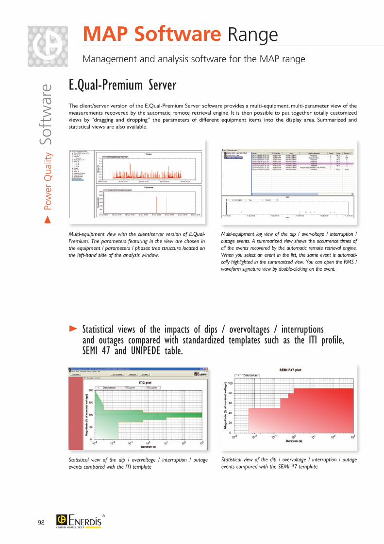
The client/server version of the E.Qual-Premium Server software provides a multi-equipment, multi-parameter view of the measurements recovered by the automatic remote retrieval engine. It is then possible to put together totally customized views by “dragging and dropping” the parameters of different equipment items into the display area. Summarized and statistical views are also available.
E.Qual-Premium Server
> Statistical views of the impacts of dips / overvoltages / interruptions and outages compared with standardized templates such as the ITI profile, SEMI 47 and UNIPEDE table.
Statistical view of the dip / overvoltage / interruption / outage events compared with the ITI template
Multi-equipment log view of the dip / overvoltage / interruption / outage events. A summarized view shows the occurrence times of all the events recovered by the automatic remote retrieval engine. When you select an event in the list, the same event is automati-cally highlighted in the summarized view. You can open the RMS / waveform signature view by double-clicking on the event.
Multi-equipment view with the client/server version of E.Qual-Premium. The parameters featuring in the view are chosen in the equipment / parameters / phases tree structure located on the left-hand side of the analysis window.
98
> Po
wer
Qua
lity S
oftw
are
MAP Software Range Management and analysis software for the MAP range
Statistical view of the dip / overvoltage / interruption / outage events compared with the SEMI 47 template.
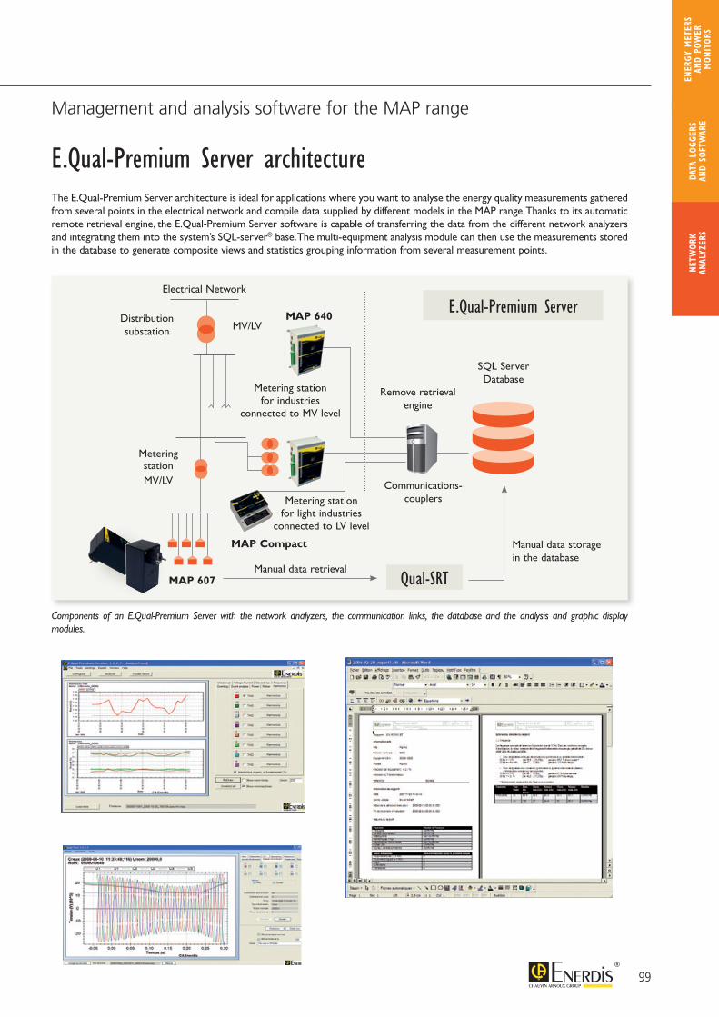
The E.Qual-Premium Server architecture is ideal for applications where you want to analyse the energy quality measurements gathered from several points in the electrical network and compile data supplied by different models in the MAP range. Thanks to its automatic remote retrieval engine, the E.Qual-Premium Server software is capable of transferring the data from the different network analyzers and integrating them into the system’s SQL-server® base. The multi-equipment analysis module can then use the measurements stored in the database to generate composite views and statistics grouping information from several measurement points.
E.Qual-Premium Server architecture
Components of an E.Qual-Premium Server with the network analyzers, the communication links, the database and the analysis and graphic display modules.
99
Management and analysis software for the MAP range
Réseau électrique
Poste de répartition
Poste de livraison
Point de livraisonpour industries
raccordées au niveau HTA
Point de livraisonpour industries légères
raccordées au niveau BT
Coupleurs de communication
Moteur deTélé-relève
Base de Données SQL-Server
HTA/BT
HTA/BT
MAP 607Qual-SRT
MAP 620
MAP 620
MAP 640E.Qual-Premium Server
MAP 620
MAP 640
Electrical Network
Manual data retrieval
Manual data storage in the database
Qual-SRTMAP 607
MAP Compact
Metering stationfor light industries
connected to LV level
Metering station
Metering stationfor industries
connected to MV level
Remove retrievalengine
Communications-couplers
SQL ServerDatabase
MV/LV
MV/LVDistributionsubstation
NETW
ORK
ANAL
YZER
SDA
TA L
OGGE
RS
AND
SOFT
WAR
E
ENER
GY M
ETER
S AN
D PO
WER
M
ONIT
ORS

PRODUCT ADVANTAGES
A DEDICATED TEAM to support your project
CUSTOMIZED AUDITS based on your specifications
Targeted studies FROM DOWNSTREAM OF THE MV/LV TRANSFORMER THROUGH TO YOUR TERMINAL DISTRIBUTION SYSTEM
The specialized engineers comprising the ENERDIS TROUBLESHOOTING DEPARTMENT propose electrical network auditing services. The goal is to help you identify the main features of your industrial, tertiary and infrastructure networks.
Analysis of the parameters liable to cause malfunctions or excessive loads on the installations.Recommendation of solutions to meet the energy quality requirements.
> Description
Enerdis uses Chauvin Arnoux® and Metrix® instruments for its troubleshooting activities
Experts carry out a totally customized study
100
Audit and Troubleshooting Department Engineers ready to listen and support any approach for electrical network optimization.
> Po
wer
Qua
lity S
ervi
ce

Power supply faults and deterioration of electrical power supply quality cause disturbances whose cost is a major concern for industrial companies. Prevention is the best strategy for dealing with harmonic distortion, outages, voltage variations and transient phenomena.
Consequences of harmonic currents on the networkOften underestimated, harmonic currents cause problems at the level of both the distribution system and the installation:- overheating of the neutral- overheating of the transformers- untimely tripping of protective devices- overloading of capacitors- skin effect in the conductors
The Enerdis Audit and Troubleshooting Department helps you to gain a better understanding of your electrical network and supports you in your search for suitable solutions.
101
Audit and Troubleshooting Department Engineers ready to listen and support any approach for electrical network optimization.
Power quality Measurement of the energy quality parameters
and compliance with the levels required by the EN 50160 standard
Evaluation of the parameters outside the template and analysis of the danger for equipment and loads downstreams
Evaluation of the interconnection parameters over several integration periods for measurement periods of up to one week
Study of the need for Power Factor Correction Evaluation of the power factor (cos ϕ) with activation
of different types of loads Study of the need for Power Factor Correction to avoid
penalties during the period of reference Recommendations for capacitor bank sizing: type of fixed/
regulated compensation, standard type of reinforcement, H or SAH
Study of harmonic pollution Measurement of harmonic pollution and evaluation at
different points in the electrical distribution system Correlation with the activation of loads causing
disturbances Global survey of harmonic pollution over a cycle
representative of the site’s load profile Recommendation of filtering solutions
Study of load profile Global energy survey of the site with study of the
power components over a significant load period Evaluation of the load on the site’s MV/LV
transformers and possible overloading Evaluation of the load profile observed
and the threshold effects on the tariff contract
Study of common-mode components Measurement of the common-mode currents
liable to cause untimely tripping of CBs Measurement of the common-mode voltages liable
to cause malfunctioning of sensitive downstream loads
Customized auditsIn the context of the TROUBLESHOOTING activity, a made-to-measure audit can be performed. Our experts carry out a customized survey of the different technical points stipulated in your specifications.
Work method: keeping as close as possible to the statement of requirements Contact to assess the precise requirements in a partnership
between the customer and ENERDIS Drafting of a customized technical and sales offer Definition of a work schedule and the work method
proposed Troubleshooting inspection by experienced staff with all the
necessary electrical authorizations needed for on-site mea-surement work
Instrumentation of the measurement points defined in the troubleshooting work method and recording of relevant measurements
Generation of a troubleshooting report with recommendations
NETW
ORK
ANAL
YZER
SDA
TA L
OGGE
RS
AND
SOFT
WAR
E
ENER
GY M
ETER
S AN
D PO
WER
M
ONIT
ORS
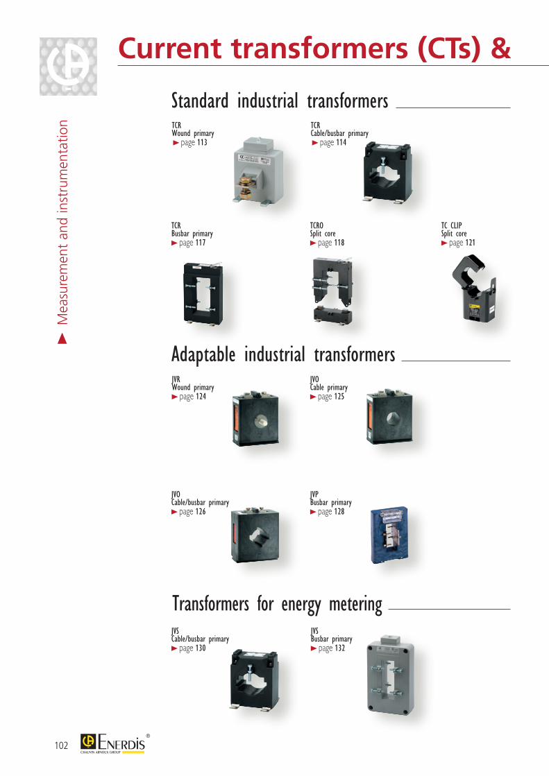
102
> M
easu
rem
ent
and
inst
rum
enta
tion
Current transformers (CTs) & shunts
TCRWound primary> page 113
TCRCable/busbar primary> page 114
TCRBusbar primary > page 117
TCROSplit core > page 118
TC CLIPSplit core > page 121
JVRWound primary > page 124
JVOCable primary > page 125
JVOCable/busbar primary > page 126
JVPBusbar primary > page 128
Standard industrial transformers
Adaptable industrial transformers
JVSCable/busbar primary > page 130
JVSBusbar primary > page 132
Transformers for energy metering
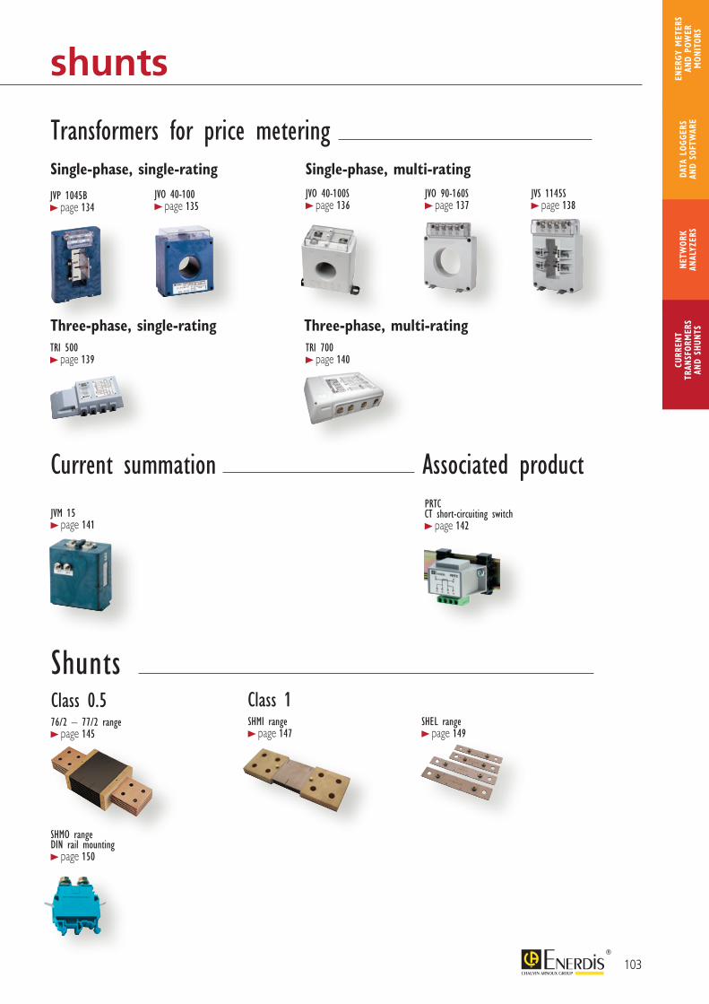
103
CURR
ENT
TRAN
SFOR
MER
SAN
D SH
UNTS
NETW
ORK
ANAL
YZER
SDA
TA L
OGGE
RS
AND
SOFT
WAR
E
ENER
GY M
ETER
S AN
D PO
WER
M
ONIT
ORS
Current transformers (CTs) & shunts
SHMI range > page 147
SHEL range > page 149
76/2 – 77/2 range > page 145
ShuntsClass 1
JVM 15 > page 141
PRTCCT short-circuiting switch > page 142
Associated productCurrent summation
Class 0.5
SHMO rangeDIN rail mounting > page 150
Transformers for price metering
JVP 1045B > page 134
Single-phase, single-rating
Three-phase, single-rating
Single-phase, multi-rating
Three-phase, multi-ratingTRI 500 > page 139
JVO 40-100 > page 135
JVO 40-100S > page 136
TRI 700 > page 140
JVO 90-160S > page 137
JVS 1145S > page 138
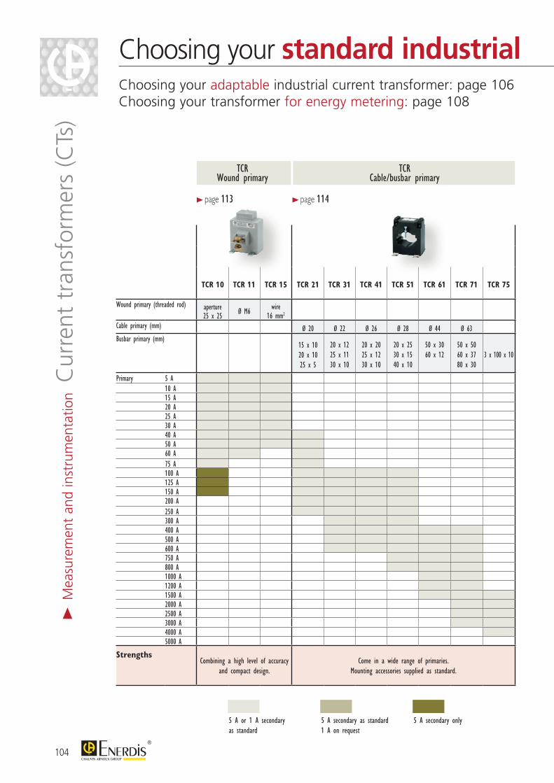
TCR 10 TCR 11 TCR 15 TCR 21 TCR 31 TCR 41 TCR 51 TCR 61 TCR 71 TCR 75 TCR 80 TCR 90 TCR 100TCRO2030
TCRO 5080
TCRO 8080
TCRO 80120
TCRO 80160
TCC 176 TCC 241 TCC 242 TCC 364 TCC 366
Wound primary (threaded rod) aperture25 x 25 Ø M6 wire
16 mm2
Cable primary (mm) Ø 20 Ø 22 Ø 26 Ø 28 Ø 44 Ø 63 Ø 17 Ø 24 Ø 24 Ø 36 Ø 36Busbar primary (mm)
15 x 1020 x 1025 x 5
20 x 1225 x 1130 x 10
20 x 2025 x 1230 x 10
20 x 2530 x 1540 x 10
50 x 3060 x 12
50 x 5060 x 3780 x 30
3 x 100 x 10100 x 20 100 x 30 1025 x 60 20 x 30 50 x 80 80 x 80 80 x 120 80 x 160
Primary 5 A10 A15 A20 A25 A30 A40 A50 A60 A75 A100 A125 A150 A200 A250 A300 A400 A500 A600 A750 A800 A1000 A1200 A1500 A2000 A2500 A3000 A4000 A5000 A
StrengthsCombining a high level of accuracy
and compact design.Come in a wide range of primaries.
Mounting accessories supplied as standard.Complete products for 100 and 125 mm
busbar type.A wide range suitable for most primaries.Installation without disconnecting busbars.
Implementation without disconnecting the power cables. Compact format.
> page 113
TCR Cable/busbar primary
TCRWound primary
> page 114
104
> M
easu
rem
ent
and
inst
rum
enta
tion C
urre
nt t
rans
form
ers
(CTs
)Choosing your standard industrialChoosing your adaptable industrial current transformer: page 106Choosing your transformer for energy metering: page 108
5 A secondary only5 A or 1 A secondary as standard
5 A secondary as standard1 A on request
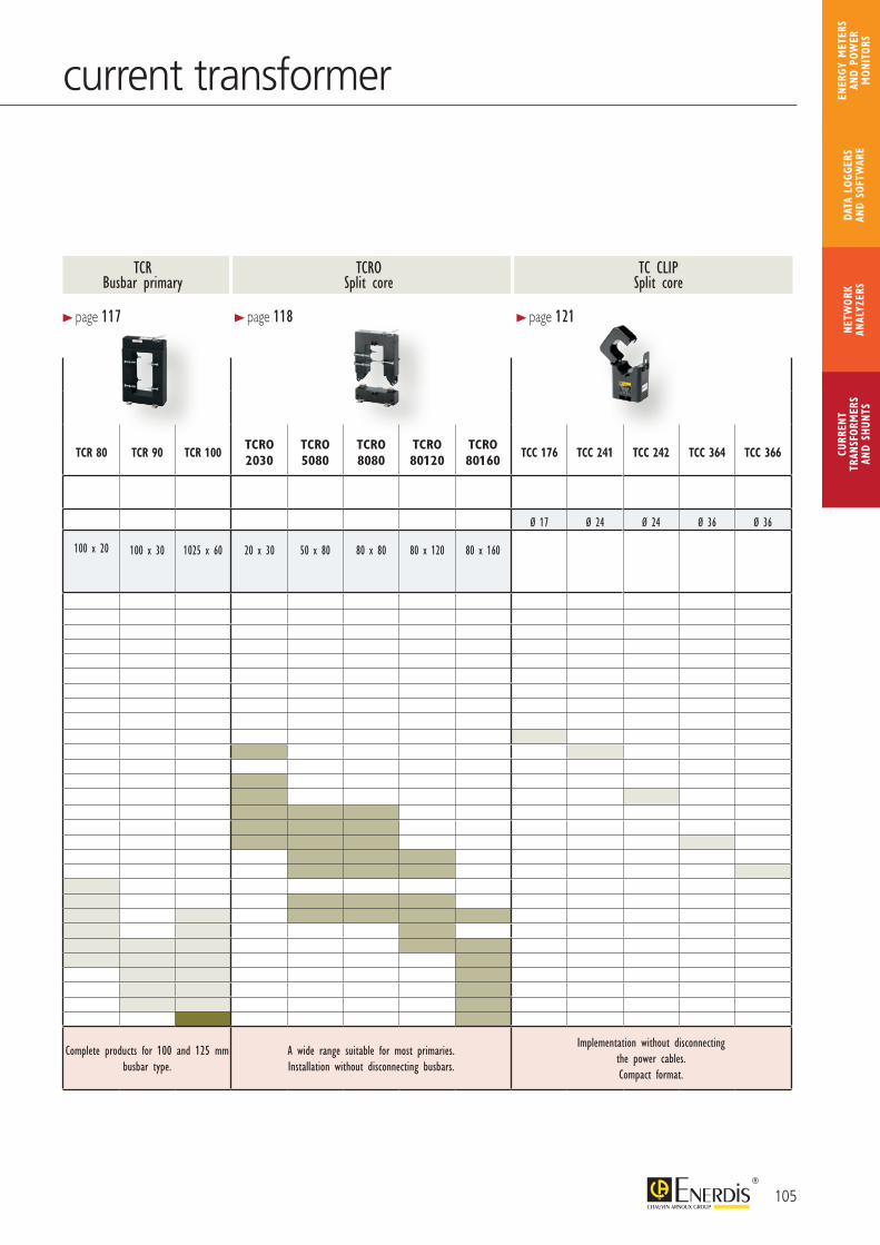
TCR 10 TCR 11 TCR 15 TCR 21 TCR 31 TCR 41 TCR 51 TCR 61 TCR 71 TCR 75 TCR 80 TCR 90 TCR 100TCRO2030
TCRO 5080
TCRO 8080
TCRO 80120
TCRO 80160
TCC 176 TCC 241 TCC 242 TCC 364 TCC 366
Wound primary (threaded rod) aperture25 x 25 Ø M6 wire
16 mm2
Cable primary (mm) Ø 20 Ø 22 Ø 26 Ø 28 Ø 44 Ø 63 Ø 17 Ø 24 Ø 24 Ø 36 Ø 36Busbar primary (mm)
15 x 1020 x 1025 x 5
20 x 1225 x 1130 x 10
20 x 2025 x 1230 x 10
20 x 2530 x 1540 x 10
50 x 3060 x 12
50 x 5060 x 3780 x 30
3 x 100 x 10100 x 20 100 x 30 1025 x 60 20 x 30 50 x 80 80 x 80 80 x 120 80 x 160
Primary 5 A10 A15 A20 A25 A30 A40 A50 A60 A75 A100 A125 A150 A200 A250 A300 A400 A500 A600 A750 A800 A1000 A1200 A1500 A2000 A2500 A3000 A4000 A5000 A
StrengthsCombining a high level of accuracy
and compact design.Come in a wide range of primaries.
Mounting accessories supplied as standard.Complete products for 100 and 125 mm
busbar type.A wide range suitable for most primaries.Installation without disconnecting busbars.
Implementation without disconnecting the power cables. Compact format.
> page 117 > page 118 > page 121
105
CURR
ENT
TRAN
SFOR
MER
SAN
D SH
UNTS
NETW
ORK
ANAL
YZER
SDA
TA L
OGGE
RS
AND
SOFT
WAR
E
ENER
GY M
ETER
S AN
D PO
WER
M
ONIT
ORS
current transformer
TCRO Split core
TC CLIP Split core
TCR Busbar primary
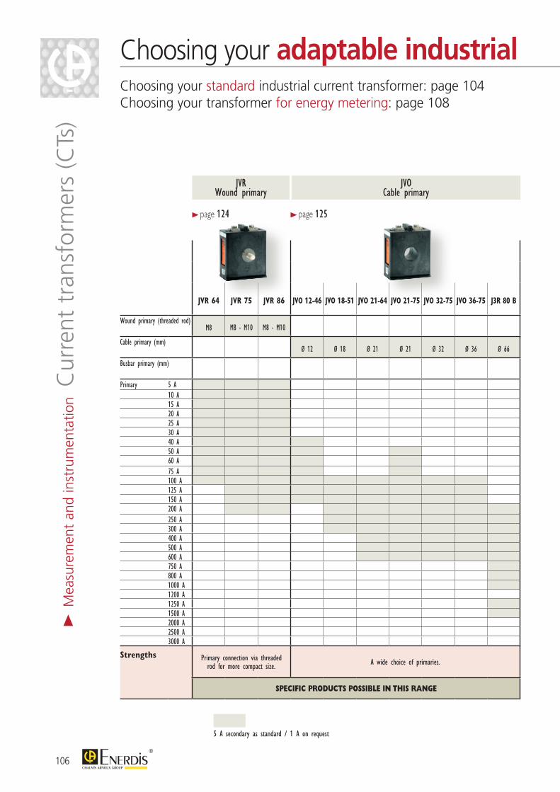
JVR 64 JVR 75 JVR 86 JVO 12-46 JVO 18-51 JVO 21-64 JVO 21-75 JVO 32-75 JVO 36-75 J3R 80 B JVO 25 CR JVO 32 CR JVP 624 JVP 1025 JVP 1045
Wound primary (threaded rod)M8 M8 - M10 M8 - M10
Cable primary (mm)Ø 12 Ø 18 Ø 21 Ø 21 Ø 32 Ø 36 Ø 66 32.5 x 10.5 40.5 x 10.5 65 x 22 105 x 22 105 x 42
Busbar primary (mm)
Primary 5 A10 A15 A20 A25 A30 A40 A50 A60 A75 A100 A125 A150 A200 A250 A300 A400 A500 A600 A750 A800 A1000 A1200 A1250 A1500 A2000 A2500 A3000 A
Strengths Primary connection via threaded rod for more compact size. A wide choice of primaries. JVO version for cable or busbar primary. A wide choice of busbars from 60 to 100 mm.
SPECIFIC PRODUCTS POSSIBLE IN THIS RANGE SPECIFIC PRODUCTS POSSIBLE IN THIS RANGE
> page 124
JVOCable primary
JVRWound primary
> page 125
5 A secondary as standard / 1 A on request
106
Choosing your adaptable industrial current transformer Choosing your standard industrial current transformer: page 104Choosing your transformer for energy metering: page 108
> M
easu
rem
ent
and
inst
rum
enta
tion C
urre
nt t
rans
form
ers
(CTs
)
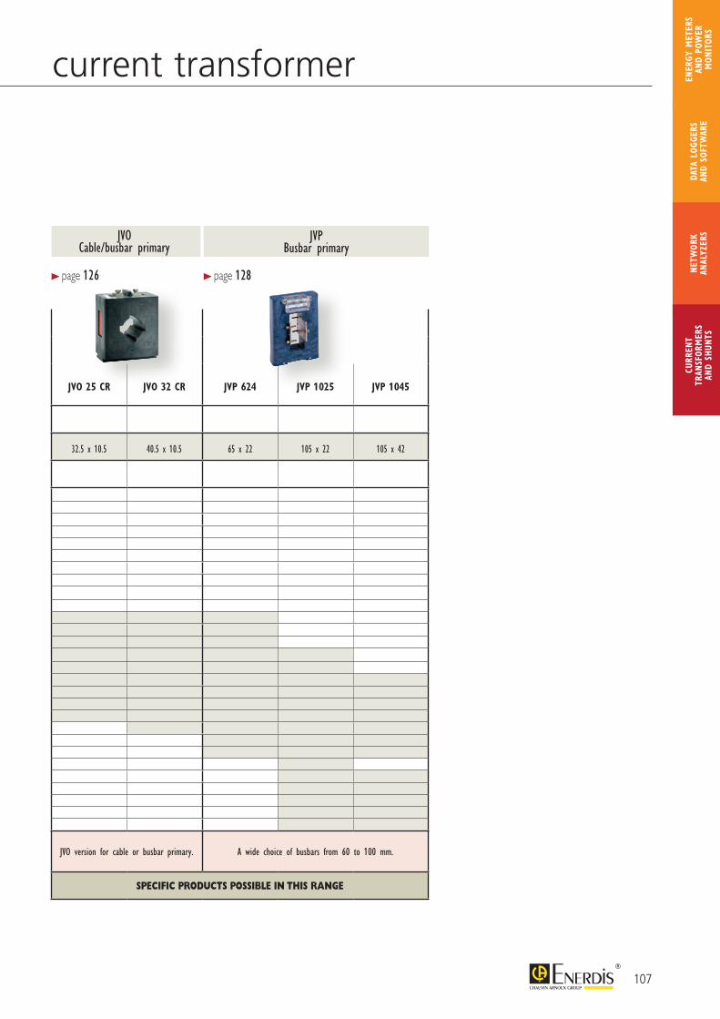
JVR 64 JVR 75 JVR 86 JVO 12-46 JVO 18-51 JVO 21-64 JVO 21-75 JVO 32-75 JVO 36-75 J3R 80 B JVO 25 CR JVO 32 CR JVP 624 JVP 1025 JVP 1045
Wound primary (threaded rod)M8 M8 - M10 M8 - M10
Cable primary (mm)Ø 12 Ø 18 Ø 21 Ø 21 Ø 32 Ø 36 Ø 66 32.5 x 10.5 40.5 x 10.5 65 x 22 105 x 22 105 x 42
Busbar primary (mm)
Primary 5 A10 A15 A20 A25 A30 A40 A50 A60 A75 A100 A125 A150 A200 A250 A300 A400 A500 A600 A750 A800 A1000 A1200 A1250 A1500 A2000 A2500 A3000 A
Strengths Primary connection via threaded rod for more compact size. A wide choice of primaries. JVO version for cable or busbar primary. A wide choice of busbars from 60 to 100 mm.
SPECIFIC PRODUCTS POSSIBLE IN THIS RANGE SPECIFIC PRODUCTS POSSIBLE IN THIS RANGE
JVOCable/busbar primary
JVPBusbar primary
> page 126 > page 128
107
CURR
ENT
TRAN
SFOR
MER
SAN
D SH
UNTS
NETW
ORK
ANAL
YZER
SDA
TA L
OGGE
RS
AND
SOFT
WAR
E
ENER
GY M
ETER
S AN
D PO
WER
M
ONIT
ORS
Choosing your adaptable industrial current transformer Choosing your standard industrial current transformer: page 104Choosing your transformer for energy metering: page 108
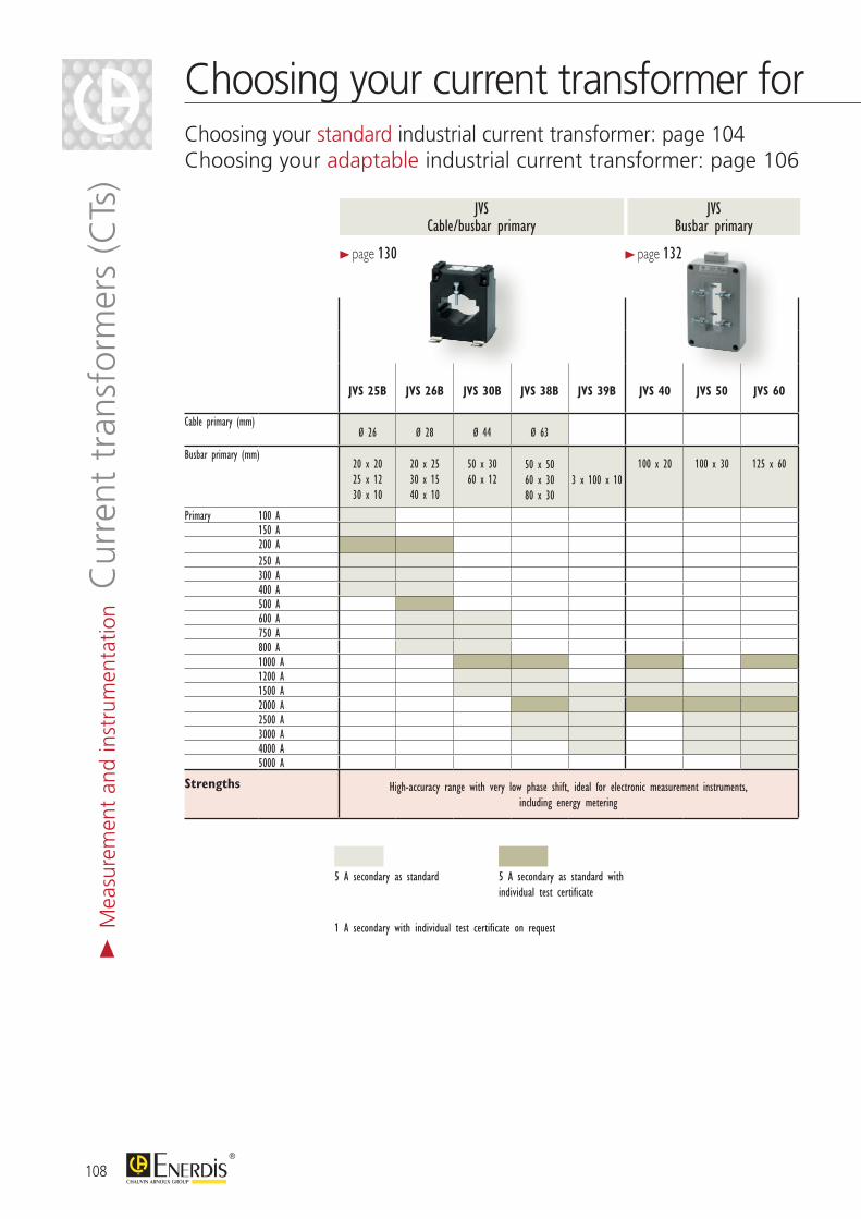
JVS 25B JVS 26B JVS 30B JVS 38B JVS 39B JVS 40 JVS 50 JVS 60
Cable primary (mm)Ø 26 Ø 28 Ø 44 Ø 63
Busbar primary (mm)20 x 2025 x 1230 x 10
20 x 2530 x 1540 x 10
50 x 3060 x 12
50 x 5060 x 3080 x 30
3 x 100 x 10100 x 20 100 x 30 125 x 60
Primary 100 A150 A200 A250 A300 A400 A500 A600 A750 A800 A1000 A1200 A1500 A2000 A2500 A3000 A4000 A5000 A
Strengths High-accuracy range with very low phase shift, ideal for electronic measurement instruments, including energy metering
> page 130
JVS Busbar primary
JVSCable/busbar primary
1 A secondary with individual test certificate on request
5 A secondary as standard 5 A secondary as standard with individual test certificate
> page 132
108
Choosing your current transformer forChoosing your standard industrial current transformer: page 104Choosing your adaptable industrial current transformer: page 106
> M
easu
rem
ent
and
inst
rum
enta
tion C
urre
nt t
rans
form
ers
(CTs
)
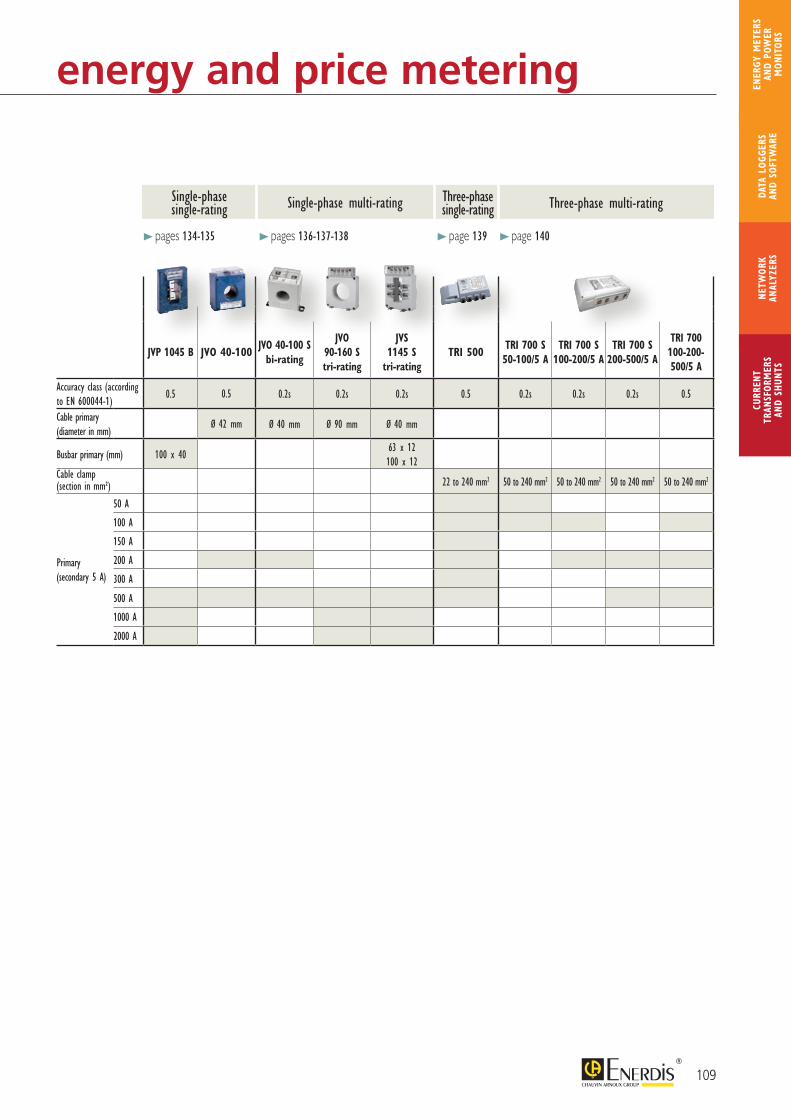
109
CURR
ENT
TRAN
SFOR
MER
SAN
D SH
UNTS
NETW
ORK
ANAL
YZER
SDA
TA L
OGGE
RS
AND
SOFT
WAR
E
ENER
GY M
ETER
S AN
D PO
WER
M
ONIT
ORS
energy and price metering
JVP 1045 B JVO 40-100JVO 40-100 S
bi-rating
JVO 90-160 S tri-rating
JVS 1145 S
tri-ratingTRI 500
TRI 700 S 50-100/5 A
TRI 700 S 100-200/5 A
TRI 700 S 200-500/5 A
TRI 700 100-200-500/5 A
Accuracy class (according to EN 600044-1)
0.5 0.5 0.2s 0.2s 0.2s 0.5 0.2s 0.2s 0.2s 0.5
Cable primary(diameter in mm)
Ø 42 mm Ø 40 mm Ø 90 mm Ø 40 mm
Busbar primary (mm) 100 x 4063 x 12 100 x 12
Cable clamp (section in mm²) 22 to 240 mm2 50 to 240 mm2 50 to 240 mm2 50 to 240 mm2 50 to 240 mm2
Primary (secondary 5 A)
50 A
100 A
150 A
200 A
300 A
500 A
1000 A
2000 A
> pages 134-135 > pages 136-137-138 > page 139 > page 140
Single-phase single-rating
Three-phase single-ratingSingle-phase multi-rating Three-phase multi-rating

110
Info & advice>
Mea
sure
men
t an
d in
stru
men
tatio
n Cur
rent
tra
nsfo
rmer
s (C
Ts)
& s
hunt
s
Determining a CT’s accuracy classThe accuracy class of a current transformer depends on the transformer’s apparent power (VA) and the consumption of the entire measurement line. It is the result of the measurement errors of each element in the line and must therefore be less than or equal to the accuracy class of the measuring instrument which it supplies, particularly for energy meter-ing where accuracy has a direct impact on billing. For a given accuracy class, the measurement line’s consumption must not exceed the current transformer’s apparent power (VA).
Example of measurement chain consumption at 20 °C
The transformer’s accuracy class can then be deduced from the results obtained by referring to the table opposite (provided as an example):- Class 3 for a CT with a ratio of 150/5- Class 1 for a CT with a ratio of 200/5- Class 0.5 for a CT with a ratio of 250/5
How to choose a current transformer?The choice is based on two main criteria:- the current on the primary (transformation ratio Ip / 5 A);- the type of installation.In other words, the choice depends on the type of cable or busbar on the installation and the intensity of the currents flowing through them.
TRANSFORMERS
FunctionCurrent transformers power low-voltage measuring instruments and isolate them from the network. They supply their secondary winding with a standard current proportional to the primary current. They are divided into four main families:- wound primaries;- split-core primaries;- cable primaries;- busbar primaries.These transformers can be used with all types of measuring instruments:ammeters, energy meters, power monitors, etc.
Power (VA) on ClassPrimary 0.5 1 3 (kg)100 A - 1 1.5 0,53125 A - 1 1.5 0,53150 A 1 1.75 2.5 0,53200 A 1.5 2.75 3.75 0,54250 A 2 3.25 3.75 0,54300 A 2.5 3.25 4 0,51400 A 3 3.75 5 0,51500 A 3.5 3.75 5 0,51600 A 3.75 5 7.5 0,52
Enerium 50 Power Monitor 0.15 VA 5 m of double 2.5 mm² wire 0.37 x 5 = 1.85 VA Measurement line consumption 0.15 + 1.85 = 2 VA
Copper-wire section (mm²) Secondary 5 A Secondary 1 A
1.5 0.61 0.025 VA 2.5 0.37 0.015 VA 4 0.23 0.009 VA 6 0.15 0.006 VA
Power dissipated per metre of line (2 ways)
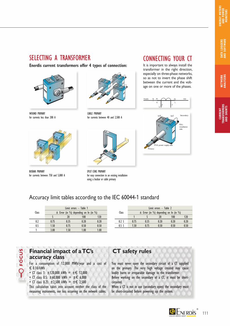
111
CURR
ENT
TRAN
SFOR
MER
SAN
D SH
UNTS
NETW
ORK
ANAL
YZER
SDA
TA L
OGGE
RS
AND
SOFT
WAR
E
ENER
GY M
ETER
S AN
D PO
WER
M
ONIT
ORS
For a consumption of 12,000 MWh/year and a cost of e 0.10/kWh• CT class 1: ±120,000 kWh = ±e 12,000• CT class 0.5: ±60,000 kWh = ±e 6,000• CT class 0.2S: ±2,500 kWh = ±e 2,500This calculation takes into account neither the class of the measuring instruments, nor loss occurring on the network cables.
You must never open the secondary circuit of a CT supplied on the primary. The very high voltage created may cause bodily harm or irreparable damage to the transformer.Before working on the secondary of a CT, it must be short-circuited.When a CT is not in use (secondary open) the secondary must be short-circuited before powering up the system.
FO
CU
S Financial impact of a TC’s accuracy class
CT safety rules
ClassLimit errors – Table 1
± Error (in %) depending on In (in %)5 20 100 120
0.2 0.75 0.35 0.20 0.200.5 1.50 0.75 0.50 0.501 3.00 1.50 1.00 1.00
ClassLimit errors – Table 2
± Error (in %) depending on In (in %)1 5 20 100 120
0.2 S 0.75 0.35 0.20 0.20 0.200.5 S 1.50 0.75 0.50 0.50 0.50
Accuracy limit tables according to the IEC 60044-1 standard
WOUND PRIMARYfor currents less than 200 A
CABLE PRIMARYfor currents between 40 and 2,500 A
BUSBAR PRIMARYfor currents between 750 and 5,000 A
SPLIT CORE PRIMARYfor easy connection to an existing installation using a busbar or cable primary
CONNECTING YOUR CTIt is important to always install the transformer in the right direction, especially on three-phase networks, so as not to invert the phase shift between the current and the volt-age on one or more of the phases.
SELECTING A TRANSFORMEREnerdis current transformers offer 4 types of connection:
P1/K: power supply side
P2/L:installationside
S1 S2
Primary
Secondary
Supply Use
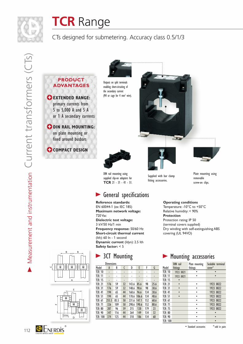
1923 00211923 0021
B
C F
B E
A DGmax
B
C F
B E
A DGmax
Dimensions Model A B C D E F GTCR 10 - - - - - - -TCR 11 - - - - - - -TCR 15 - - - - - - -TCR 21 176 59 32 143.6 85.6 98 25.6TCR 31 176 59 32 148.6 90.6 98 30.6TCR 41 194 65 44 160.6 96.6 134 30.6TCR 51 194 65 44 170.6 106.6 134 40.6TCR 61 255.5 85.5 50 231.6 147.1 152 60.6TCR 71 326 109 50 298.6 190.6 152 80.6TCR 80 287 96 59 215 120 179 23TCR 90 347 116 44 264 149 134 32TCR 100 374 125 44 310 186 134 60
DIN rail Plate mounting Sealable terminalModel fittings fittings cover*TCR 10 • •TCR 11 • •TCR 15 •TCR 21 • • 1923 0022TCR 31 • • 1923 0022TCR 41 • • 1923 0022TCR 51 • • 1923 0022TCR 61 • 1923 0022TCR 71 • 1923 0022TCR 75 • 1923 0022TCR 80 • •TCR 90 • •TCR 100 • •
• Standard accessories * sold in pairs
Outputs on split terminals enabling short-circuiting of the secondary current (M4 or cage for 4 mm2 wire).
Supplied with bar clamp fitting accessories.
Reference standards:EN 60044-1 (ex IEC 185)Maximum network voltage: 720 VacDielectric test voltage:3 kV/50 Hz/1 minFrequency response: 50/60 HzShort-circuit thermal current(Ith): 60 In - 1 secondDynamic current (Idyn): 2.5 IthSafety factor: < 5
Operating conditionsTemperature: -10°C to +50°CRelative humidity: < 90%ProtectionProtection rating: IP 50 (terminal covers supplied)Dry winding with self-extinguishing ABS covering (UL 94VO)
> General specifications
DIN rail mounting using supplied clip-on adapters for TCR 21 - 31 - 41 - 51.
Plate mounting using removable screw-on clips.
> 3CT Mounting > Mounting accessories
112
TCR RangeCTs designed for submetering. Accuracy class 0.5/1/3
> M
easu
rem
ent
and
inst
rum
enta
tion C
urre
nt t
rans
form
ers
(CTs
)
EXTENDED RANGE: primary currents from
5 to 5,000 A and 5 A or 1 A secondary currents
DIN RAIL MOUNTING: on plate mounting or
fixed around busbars
COMPACT DESIGN
PRODUCT ADVANTAGES
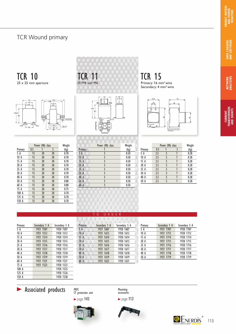
T O O R D E R
104.5
10.5 10.5
82
7543
50
5080
40
32108
134
Ø 5.5
M10X25
104.5
10.5 10.5
82
7543
50
5080
40
32108
134
Ø 5.5
M10X25
DIN 46277 (EN 50022)
FIXATION
PRIMARY
SECONDARY
52.5 70
4820
85 45
M 6 M 4
10
50
50
82
75 4043 32
104
Ø 5,5
P1
P2
S1
S2
M 6 M 4
10
50
50
82
75 4043 32
104
Ø 5,5
P1
P2
S1
S2
Power (VA) class WeightPrimary 0.5 1 3 (kg)5 A 2.5 5 7 0.2810 A 2.5 5 7 0.2815 A 2.5 5 7 0.2820 A 2.5 5 7 0.2825 A 2.5 5 7 0.2830 A 2.5 5 7 0.2840 A 2.5 5 7 0.2850 A 2.5 5 7 0.28
Power (VA) class WeightPrimary 1 (kg)5 A 5 0.5010 A 5 0.5015 A 5 0.5020 A 5 0.5025 A 5 0.5030 A 5 0.5040 A 5 0.5050 A 5 0.5060 A 5 0.50
Power (VA) class WeightPrimary 0.5 1 3 (kg)5 A 15 20 30 0.7010 A 15 20 30 0.7015 A 15 20 30 0.7020 A 15 20 30 0.7025 A 15 20 30 0.7030 A 15 20 30 0.7040 A 15 20 30 0.7050 A 15 20 30 0.8060 A 15 20 30 0.8075 A 15 20 30 0.75100 A 15 20 30 0.70125 A 15 20 30 0.70150 A 15 20 30 0.70
Primary Secondary 1 A Secondary 5 A5 A 1921 1507 1920 150710 A 1921 1512 1920 151215 A 1921 1514 1920 151420 A 1921 1515 1920 151525 A 1921 1516 1920 151630 A 1921 1517 1920 151740 A 1921 1518 1920 151850 A 1921 1519 1920 151960 A 1921 1521 1920 152175 A 1921 1523 1920 1523100 A 1920 1525125 A 1920 1526150 A 1920 1528
Primary Secondary 1 A Secondary 5 A5 A 1921 1607 1920 160710 A 1921 1612 1920 161215 A 1921 1614 1920 161420 A 1921 1615 1920 161525 A 1921 1616 1920 161630 A 1921 1617 1920 161740 A 1921 1618 1920 161850 A 1921 1619 1920 161960 A 1921 1621 1920 1621
Primary Secondary 1 A Secondary 5 A5 A 1921 1707 1920 170710 A 1921 1712 1920 171215 A 1921 1714 1920 171420 A 1921 1715 1920 171525 A 1921 1716 1920 171630 A 1921 1717 1920 171740 A 1921 1718 1920 171850 A 1921 1719 1920 1719
TCR 10 TCR 15TCR 1125 x 25 mm aperture Ø M4 and M6 Primary: 16 mm2 wire
Secondary: 4 mm2 wire
TCR Wound primary
113
CURR
ENT
TRAN
SFOR
MER
SAN
D SH
UNTS
NETW
ORK
ANAL
YZER
SDA
TA L
OGGE
RS
AND
SOFT
WAR
E
ENER
GY M
ETER
S AN
D PO
WER
M
ONIT
ORS
PRTC CT protection unit
> page 143
Mounting accessories
> page 112
> Associated products
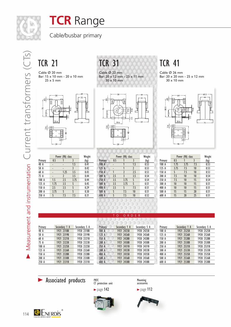
T O O R D E R
25.6
58
4.5
70
29
5.6
15.6
48
2.5
20.3
49
32
59
39
P1
S2
P2
S15.5
25.6
58
4.5
70
29
5.6
15.6
48
2.5
20.3
49
32
59
39
P1
S2
P2
S15.5
30.6
58
4.5
70
29
20.62.5
5.6
48
49
32
59
39
P1
S2
P2
22.3
10.6
30.6
58
4.5
70
29
20.62.5
5.6
48
49
32
59
39
P1
S2
P2
22.3
10.6
30.6
64
80.5
344.
5
20.62.5
60.544
71
5.6
60
46
P1
S2
P2
S1
26
10.6
30.6
64
80.5
344.
5
20.62.5
60.544
71
5.6
60
46
P1
S2
P2
S1
26
10.6
Power (VA) class WeightPrimary 0.5 1 3 (kg)100 A 1.75 3.75 7.5 0.53125 A 3.75 7.5 10 0.53150 A 5 7.5 10 0.53200 A 7.5 10 10 0.54250 A 7.5 10 15 0.54300 A 10 10 15 0.51400 A 10 10 15 0.51500 A 15 15 20 0.51600 A 15 20 25 0.51
Power (VA) class WeightPrimary 0.5 1 3 (kg)100 A - 1 1.5 0.53125 A - 1 2 0.53150 A 1 2 2.5 0.53200 A 2.5 3 3.5 0.54250 A 3.5 3.75 5 0.54300 A 3.5 3.75 5 0.51400 A 3.5 5 7.5 0.51500 A 5 7.5 10 0.51600 A 5 7.5 10 0.52
Power (VA) class WeightPrimary 0.5 1 3 (kg)40 A - - 1.5 0.4150 A - - 3 0.4260 A - 1.25 3.5 0.4375 A - 2 3.5 0.44100 A 1.5 2.5 3.75 0.44125 A 1.75 3.5 5 0.45150 A 2.5 3.5 5 0.29200 A 3.75 5 5 0.30250 A 5 7.5 7.5 0.31
Primary Secondary 1 A Secondary 5 A40 A 1921 2318B 1920 2318B50 A 1921 2319B 1920 2319B60 A 1921 2321B 1920 2321B75 A 1921 2323B 1920 2323B100 A 1921 2325B 1920 2325B125 A 1921 2326B 1920 2326B150 A 1921 2328B 1920 2328B200 A 1921 2330B 1920 2330B250 A 1921 2331B 1920 2331B
Primary Secondary 1 A Secondary 5 A100 A 1921 2425B 1920 2425B125 A 1921 2426B 1920 2426B150 A 1921 2428B 1920 2428B200 A 1921 2430B 1920 2430B250 A 1921 2431B 1920 2431B300 A 1921 2433B 1920 2433B400 A 1921 2435B 1920 2435B500 A 1921 2436B 1920 2436B600 A 1921 2438B 1920 2438B
Primary Secondary 1 A Secondary 5 A100 A 1921 2525B 1920 2525B125 A 1921 2526B 1920 2526B150 A 1921 2528B 1920 2528B200 A 1921 2530B 1920 2530B250 A 1921 2531B 1920 2531B300 A 1921 2533B 1920 2533B400 A 1921 2535B 1920 2535B500 A 1921 2536B 1920 2536B600 A 1921 2538B 1920 2538B
Cable Ø 20 mm Bar: 15 x 10 mm - 20 x 10 mm
25 x 5 mm
Cable Ø 22 mm Bar: 20 x 12 mm - 25 x 11 mm
30 x 10 mm
Cable Ø 26 mm Bar: 20 x 20 mm - 25 x 12 mm
30 x 10 mm
TCR 21 TCR 31 TCR 41
114
TCR RangeCable/busbar primary
> M
easu
rem
ent
and
inst
rum
enta
tion C
urre
nt t
rans
form
ers
(CTs
)
PRTC CT protection unit
> page 142
Mounting accessories
> page 112
> Associated products
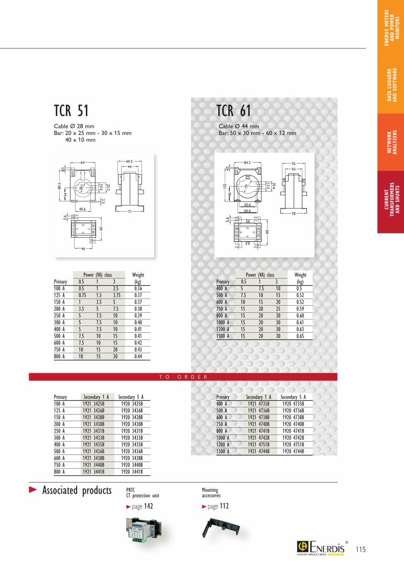
T O O R D E R
40.6
64
80.5
34
25.22.5
4.5
28.5
60.544
71
5.6
60
46
P1
S2
P2
S1
10.6
40.6
64
80.5
34
25.22.5
4.5
28.5
60.544
71
5.6
60
46
P1
S2
P2
S1
10.6
50.6
60.6
84.5
102
46
30.6
12.544
4.5
76
50
78
5.6
60
P1
S2
P2
S1
50.6
60.6
84.5
102
46
30.6
12.544
4.5
76
50
78
5.6
60
P1
S2
P2
S1
Power (VA) class WeightPrimary 0.5 1 3 (kg)400 A 5 7.5 10 0.5500 A 7.5 10 15 0.52600 A 10 15 20 0.52750 A 15 20 25 0.59800 A 15 20 30 0.601000 A 15 20 30 0.611200 A 15 20 30 0.631500 A 15 20 30 0.65
Power (VA) class WeightPrimary 0.5 1 3 (kg)100 A 0.5 1 2.5 0.36125 A 0.75 1.5 3.75 0.37150 A 1 3.5 5 0.37200 A 3.5 5 7.5 0.38250 A 5 7.5 10 0.39300 A 5 7.5 10 0.40400 A 5 7.5 10 0.41500 A 7.5 10 15 0.41600 A 7.5 10 15 0.42750 A 10 15 20 0.43800 A 10 15 20 0.44
Primary Secondary 1 A Secondary 5 A400 A 1921 4735B 1920 4735B500 A 1921 4736B 1920 4736B600 A 1921 4738B 1920 4738B750 A 1921 4740B 1920 4740B800 A 1921 4741B 1920 4741B1000 A 1921 4742B 1920 4742B1200 A 1921 4751B 1920 4751B1500 A 1921 4744B 1920 4744B
Primary Secondary 1 A Secondary 5 A100 A 1921 3425B 1920 3425B125 A 1921 3426B 1920 3426B150 A 1921 3428B 1920 3428B200 A 1921 3430B 1920 3430B250 A 1921 3431B 1920 3431B300 A 1921 3433B 1920 3433B400 A 1921 3435B 1920 3435B500 A 1921 3436B 1920 3436B600 A 1921 3438B 1920 3438B750 A 1921 3440B 1920 3440B800 A 1921 3441B 1920 3441B
Cable Ø 28 mm Bar: 20 x 25 mm - 30 x 15 mm
40 x 10 mm
Cable Ø 44 mmBar: 50 x 30 mm - 60 x 12 mm
TCR 51 TCR 61
115
CURR
ENT
TRAN
SFOR
MER
SAN
D SH
UNTS
NETW
ORK
ANAL
YZER
SDA
TA L
OGGE
RS
AND
SOFT
WAR
E
ENER
GY M
ETER
S AN
D PO
WER
M
ONIT
ORS
PRTC CT protection unit
> page 142
Mounting accessories
> page 112
> Associated products
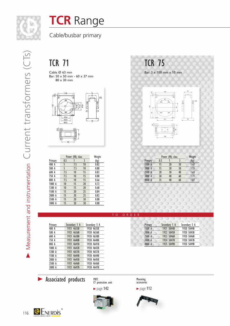
T O O R D E R
PRTC CT protection unit
> page 142
Power (VA) class WeightPrimary 0.5 1 3 (kg)400 A 5 7.5 10 0.82500 A 5 7.5 10 0.80600 A 7.5 10 15 0.83750 A 7.5 10 15 0.88800 A 7.5 10 15 0.661000 A 10 15 20 0.721200 A 10 15 20 0.681500 A 15 20 25 0.842000 A 15 20 25 0.822500 A 15 20 30 0.883000 A 15 20 30 0.88
Primary Secondary 1 A Secondary 5 A400 A 1921 4635B 1920 4635B500 A 1921 4636B 1920 4636B600 A 1921 4638B 1920 4638B750 A 1921 4640B 1920 4640B800 A 1921 4641B 1920 4641B1000 A 1921 4642B 1920 4642B1200 A 1921 4651B 1920 4651B1500 A 1921 4644B 1920 4644B2000 A 1921 4645B 1920 4645B2500 A 1921 4646B 1920 4646B3000 A 1921 4647B 1920 4647B
50,6
80,6
60,6
108
130
86
61
50,837,630,6
4,5
50 78
M5
6,6
64
63
50,6
80,660,6
108
130
86
61
50,837,630,6
4,5 50
78
M5 6,6
64
63
76
Cable Ø 63 mm Bar: 50 x 50 mm - 60 x 37 mm
80 x 30 mm
TCR 71
Mounting accessories
> page 112
Power (VA) class WeightPrimary 0.5 1 3 (kg)1500 A 15 20 30 1.472000 A 15 20 30 1.552500 A 20 30 40 1.633000 A 30 40 60 1.714000 A 35 40 60 1.87
Primary Secondary 1 A Secondary 5 A1500 A 1921 5044B 1920 5044B2000 A 1922 5045B 1920 5045B2500 A 1923 5046B 1920 5046B3000 A 1924 5047B 1920 5047B4000 A 1925 5049B 1920 5049B
704,5
150
50
78
P2
P1
S2S1
129
6,6
106
64
101
54
50M5
Bar: 3 x 100 mm x 10 mm
TCR 75
116
TCR RangeCable/busbar primary
> M
easu
rem
ent
and
inst
rum
enta
tion C
urre
nt t
rans
form
ers
(CTs
)
> Associated products

T O O R D E R
82.5
187.
516
5
235940
324395
103
11543 32
103
202.5
185
90
326344
44124
323232
38
60
78
72
71
62
57
5527
128193
Power (VA) class WeightPrimary 0.5 1 3 (kg)750 A 15 20 30 0.80800 A 15 20 30 0.801000 A 15 20 30 0.761200 A 15 20 30 0.761500 A 15 30 40 0.762000 A 20 40 50 0.76
Power (VA) class WeightPrimary 0.5 1 3 (kg)1500 A 15 30 40 0.762000 A 20 40 50 0.822500 A 20 40 50 0.783000 A 20 45 60 0.904000 A 35 50 70 0.90
Power (VA) class WeightPrimary 0.5 1 3 (kg)1000 A 15 20 30 0.751200 A 15 20 30 0.801500 A 15 20 30 0.832000 A 15 20 30 0.922500 A 20 30 40 1.013000 A 30 40 60 1.094000 A 35 50 70 1.215000 A 40 60 80 1.44
Primary Secondary 1 A Secondary 5 A750 A 1921 5640 1920 5640800 A 1921 5641 1920 56411000 A 1921 5642 1920 56421200 A 1921 5651 1920 56511500 A 1921 5644 1920 56442000 A 1921 5645 1920 5645
Primary Secondary 1 A Secondary 5 A1500 A 1921 6644 1920 66442000 A 1921 6645 1920 66452500 A 1921 6646 1920 66463000 A 1921 6647 1920 66474000 A 1921 6649 1920 6649
Primary Secondary 1 A Secondary 5 A1000 A 1921 6842 1920 68421200 A 1921 6851 1920 68511500 A 1921 6844 1920 68442000 A 1921 6845 1920 68452500 A 1921 6846 1920 68463000 A 1921 6847 1920 68474000 A 1921 6849 1920 68495000 A 1920 6850
Bar: 100 x 20 mm
TCR 80Bar: 100 x 30 mm
TCR 100TCR 90Bar: 125 x 60 mm
PRTC CT protection unit
> page 142
117
CURR
ENT
TRAN
SFOR
MER
SAN
D SH
UNTS
NETW
ORK
ANAL
YZER
SDA
TA L
OGGE
RS
AND
SOFT
WAR
E
ENER
GY M
ETER
S AN
D PO
WER
M
ONIT
ORS
TCR RangeBusbar primary
> Associated products
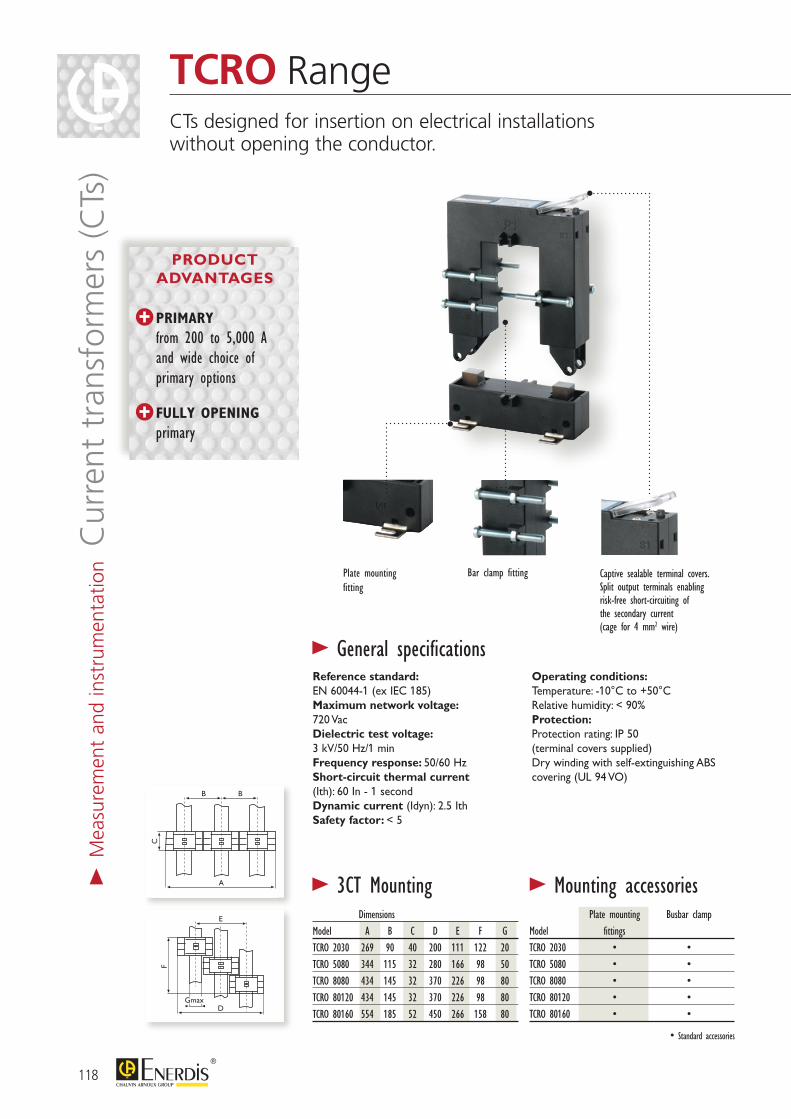
Plate mounting Busbar clampModel fittingsTCRO 2030 • •TCRO 5080 • •TCRO 8080 • •TCRO 80120 • •TCRO 80160 • •
118
TCRO RangeCTs designed for insertion on electrical installations without opening the conductor.
> M
easu
rem
ent
and
inst
rum
enta
tion C
urre
nt t
rans
form
ers
(CTs
)
B
C F
B E
A DGmax
B
C F
B E
A DGmax
Dimensions Model A B C D E F GTCRO 2030 269 90 40 200 111 122 20TCRO 5080 344 115 32 280 166 98 50TCRO 8080 434 145 32 370 226 98 80TCRO 80120 434 145 32 370 226 98 80TCRO 80160 554 185 52 450 266 158 80
• Standard accessories
Reference standard: EN 60044-1 (ex IEC 185)Maximum network voltage:720 VacDielectric test voltage:3 kV/50 Hz/1 minFrequency response: 50/60 HzShort-circuit thermal current (Ith): 60 In - 1 secondDynamic current (Idyn): 2.5 IthSafety factor: < 5
Operating conditions:Temperature: -10°C to +50°CRelative humidity: < 90%Protection:Protection rating: IP 50 (terminal covers supplied)Dry winding with self-extinguishing ABS covering (UL 94 VO)
> General specifications
> 3CT Mounting > Mounting accessories
Captive sealable terminal covers.Split output terminals enabling risk-free short-circuiting of the secondary current (cage for 4 mm2 wire)
Bar clamp fittingPlate mounting fitting
PRIMARY
from 200 to 5,000 A and wide choice of primary options
FULLY OPENING
primary
PRODUCT ADVANTAGES
T O O R D E R
110
89
20
30
5940
145
114
50
80
5932
145
144
80
80
5932
185
80
120
5932
245
80
144 184
160
5952
110
89
20
30
5940
145
114
50
80
5932
145
144
80
80
5932
185
80
120
5932
245
80
144 184
160
5952
110
89
20
30
5940
145
114
50
80
5932
145
144
80
80
5932
185
80
120
5932
245
80
144 184
160
5952
Bar: 20 x 30 mm
Power (VA) class WeightPrimary 0.5 1 3 (kg)100 A - - 1.5 0.75150 A - - 2 0.75200 A - 1.5 2.5 0.75250 A - 2 4 0.75300 A 1.5 4 6 0.75400 A 2.5 6 10 0.75
Power (VA) class WeightPrimary 0.5 1 3 (kg)250 A 1 2 4 0.90300 A 1.5 3 6 0.90400 A 1.5 3 10 0.90500 A 2.5 5 15 0.90600 A 2.5 5 17.5 0.90800 A 3 7 18 0.901000 A 5 10 20 0.90
Power (VA) class WeightPrimary 0.5 1 3 (kg)250 A 1 2 4 1.00300 A 1.5 3 6 1.00400 A 1.5 3 10 1.00500 A 2.5 5 15 1.00600 A 2.5 5 17.5 1.00800 A 3 7 18 1.001000 A 5 10 20 1.00
TCRO 2030Bar: 50 x 80 mm Bar: 80 x 80 mm
TCRO 5080 TCRO 8080
Primary Secondary 5 A100 A 1920 8328150 A 1920 8329200 A 1920 8330250 A 1920 8331300 A 1920 8333400 A 1920 8335
Primary Secondary 5 A250 A 1920 8431300 A 1920 8433400 A 1920 8435500 A 1920 8436600 A 1920 8438800 A 1920 84411000 A 1920 8442
Primary Secondary 5 A250 A 1920 8531300 A 1920 8533400 A 1920 8535500 A 1920 8536600 A 1920 8538800 A 1920 85411000 A 1920 85421 A on request
1 A secondary on request 1 A secondary on request
PRTC CT protection unit
> page 142
> Associated products
119
CURR
ENT
TRAN
SFOR
MER
SAN
D SH
UNTS
NETW
ORK
ANAL
YZER
SDA
TA L
OGGE
RS
AND
SOFT
WAR
E
ENER
GY M
ETER
S AN
D PO
WER
M
ONIT
ORS
T O O R D E R
Primary Secondary 5 A500 A 1920 8636600 A 1920 8638800 A 1920 86411000 A 1920 86421200 A 1920 86431500 A 1920 8644
Primary Secondary 5 A1000 A 1920 87421500 A 1920 87442000 A 1920 87452500 A 1920 87463000 A 1920 87474000 A 1920 87495000 A 1920 8750
Power (VA) class WeightPrimary 0.5 1 3 (kg)1000 A 10 15 20 3.501500 A 15 20 25 3.502000 A 15 20 25 3.502500 A 15 20 25 3.503000 A 20 25 30 3.504000 A 20 25 30 3.505000 A 20 25 30 3.50
120
TCRO RangeSplit core
110
89
20
30
5940
145
114
50
80
5932
145
144
80
80
5932
185
80
120
5932
245
80
144 184
160
5952
110
89
20
30
5940
145
114
50
80
5932
145
144
80
80
5932
185
80
120
5932
245
80
144 184
160
5952
Power (VA) class WeightPrimary 0.5 1 3 (kg)500 A - 4 12 1.20600 A - 5 14 1.20800 A 3 7 18 1.201000 A 5 9 20 1.201200 A 6 11 28 1.201500 A 8 17 30 1.20
Bar: 80 x 120 mm
TCRO 80120Bar: 80 x 160 mm
TCRO 80160
1 A on request
PRTCCT protection unit
> page 142
> Associated products
1 A on request
> M
easu
rem
ent
and
inst
rum
enta
tion C
urre
nt t
rans
form
ers
(CTs
)

121
CURR
ENT
TRAN
SFOR
MER
SAN
D SH
UNTS
NETW
ORK
ANAL
YZER
SDA
TA L
OGGE
RS
AND
SOFT
WAR
E
ENER
GY M
ETER
S AN
D PO
WER
M
ONIT
ORS
TC CLIP RangeVery compact current transformer for inclusion on electrical installations without disconnecting the power cables
Maximum network voltage: 720 VacDielectric test voltage: 3 kV 50 Hz 1 minSecondary current: 1 APower: 0.5 VAFrequency: 50/60 HzOperating temperature: -20°C to +50°CStorage temperature: -30°C to 90°CAccuracy class: 1 %
The TC CLIP models are compatible with all the measuring products with input on CT available on the market, and particularly ENERIUM power monitors and ULYS submeters from ENERDIS.®
> General specifications
PRODUCT ADVANTAGES
QUICK AND EASY IMPLEMENTATION without cutting off the power
Built-in SHORT- CIRCUITING SWITCH
REINFORCED HINGE
VERY COMPACT
PRIMARY from 60 to 600 A
122
> M
easu
rem
ent
and
inst
rum
enta
tion C
urre
nt t
rans
form
ers
(CTs
)
RENOV ENERGY Metering solutions
> page 52
TCC241 / TCC242
Cable Ø 24 mm
T O O R D E R
TCC176
Cable Ø 17 mm
TCC364 / TCC366
Cable Ø 36 mm
Model Primary / Secondary Reference
TCC 176 60 A / 1 A P01379609TCC 241 100 A / 1 A P01379601
TCC 242 250 A / 1 A P01379602
TCC 364 400 A / 1 A P01379603TCC 366 600 A / 1 A P01379604
TCC 176 TCC 241 TCC 242 TCC 364 TCC 366Primary 60 A 100 A 250 A 400 A 600 ASecondary 1A
Power 0,2 VA 0,5 VA
Accuracy class 3 % 1 %
Diameter 17 mm 24 mm 24 mm 36 mm 36 mm
Dimensions (mm) 64 x 33 x 34,4 74,5 x 45 x 34 74,5 x 45 x 34 91 x 57 x 40,5 91 x 57 x 40,5Weight (g) 128 162 187 263 300
Pack of 3 TC CLIP Reference
Pack of 3 TCC 176 P01379610Pack of 3 TCC 241 P01379605
Pack of 3 TCC 242 P01379606
Pack of 3 TCC 364 P01379607Pack of 3 TCC 366 P01379608
> Associated products

123
CURR
ENT
TRAN
SFOR
MER
SAN
D SH
UNTS
NETW
ORK
ANAL
YZER
SDA
TA L
OGGE
RS
AND
SOFT
WAR
E
ENER
GY M
ETER
S AN
D PO
WER
M
ONIT
ORS
B
C F
B E
A DGmax
B
C F
B E
A DGmax
Sealable coverM5 terminals with 2 grooves for dual connection on secondary
Central pipe accessory on cable primary JVO for compact lateral primary connection
Mounting on symmetrical rail (except for JVP) or plate mounting in cabinet
Reference standard: EN 60044-1(ex IEC 185)Maximum network voltage:720 VacDielectric test voltage:3 kV/50 Hz/1 minFrequency response: 50/60 HzShort-circuit thermal current (Ith):JVO, JVP: 80 InJVR 86: 60 InJVR 64, JVR 75: 40 In
Dynamic current (Idyn): 2.5 IthSafety factor: 5 in Class 1Operating conditions:Temperature: -5°C to +50°CRelative humidity: 93% at 40°CProtection:Protection rating: IP 50(with terminal cover supplied)Dry winding with self-extinguishing ABS covering (UL 94 VO)
> General specifications
> 3 CT mounting > Mounting accessories Dimensions Model A B C D E F GJVO 25 CR 227 76 45 184.5 109.5 137 32.5JVO 32 CR 260 87 58 214.5 128.5 176 40.5JVP 624 296 99 35 220 122 107 22JVP 1025 344 115 45 252 138 137 22JVP 1045 404 135 45 312 178 137 42
For 1CT 2CT 3CT model mounting rail mounting rail mounting railJVRJVO 12-18JVO 21-25-32-36J3R 80 B
ACCE 7652
ACCE 7650
ACCE 7652
ACCE 7640
ACCE 7653
ACCE 7651
ACCE 7653
ACCE 7655
ACCE 7654
ACCE 7655
JVR-JVO-JVP RangesCTs designed to supply analogue or digital measurement instruments. Accuracy class 0.5/1/3
COMPLETE RANGE: primary from 1 to 3,000 A and 5 A or 1 A secondary
TOTALLY ADAPTABLE RANGE for specific requirements (primary, secondary, power class, frequency)
PRODUCT ADVANTAGES
Pack of 3 TC CLIP Reference
Pack of 3 TCC 176 P01379610Pack of 3 TCC 241 P01379605
Pack of 3 TCC 242 P01379606
Pack of 3 TCC 364 P01379607Pack of 3 TCC 366 P01379608
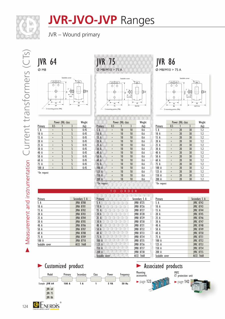
124
T O O R D E R
Power (VA) class WeightPrimary 0.5 1 3 (kg)5 A * 5 5 0.4510 A * 5 5 0.4515 A * 5 5 0.4520 A * 5 5 0.4525 A * 5 5 0.4530 A * 5 5 0.4540 A * 5 5 0.4550 A * 5 5 0.4560 A * 5 5 0.4575 A * 5 5 0.45100 A * 5 5 0.45
Power (VA) class WeightPrimary 0.5 1 3 (kg)5 A * 10 10 0.610 A * 10 10 0.615 A * 10 10 0.620 A * 10 10 0.625 A * 10 10 0.630 A * 10 10 0.640 A * 10 10 0.650 A * 10 10 0.660 A * 10 10 0.675 A * 10 10 0.6100 A * 10 10 0.6125 A * 10 10 0.6150 A * 10 10 0.6200 A * 10 10 0.6
Power (VA) class WeightPrimary 0.5 1 3 (kg)5 A * 20 30 1.210 A * 20 30 1.215 A * 20 30 1.220 A * 20 30 1.225 A * 20 30 1.230 A * 20 30 1.240 A * 20 30 1.250 A * 20 30 1.260 A * 20 30 1.275 A * 20 30 1.2100 A * 20 30 1.2125 A * 20 30 1.2150 A * 20 30 1.2200 A * 20 30 1.2
Primary Secondary 5 A5 A JVRA 870010 A JVRA 870115 A JVRA 870220 A JVRA 870325 A JVRA 870430 A JVRA 870540 A JVRA 870650 A JVRA 870760 A JVRA 870875 A JVRA 8709100 A JVRA 8710Sealable cover ACCE 7668
JVR-JVO-JVP Ranges JVR – Wound primary
42
16.5
79
ÿ
Sealable cover
2 mounting points (M6)
38
64 84
45
16.5/20
93
ÿ
Sealable cover
2 mounting points (M6)
45
75 94/101
56
16.5/20
104,
5
ÿ
Sealable cover
2 mounting points (M6)
58
86 107/114
42
16.5
79
ÿ
Sealable cover
2 mounting points (M6)
38
64 84
45
16.5/20
93
ÿ
Sealable cover
2 mounting points (M6)
45
75 94/101
56
16.5/20
104,
5ÿ
Sealable cover
2 mounting points (M6)
58
86 107/114
42
16.5
79
ÿ
Sealable cover
2 mounting points (M6)
38
64 84
45
16.5/20
93
ÿ
Sealable cover
2 mounting points (M6)
45
75 94/101
56
16.5/20
104,
5
ÿ
Sealable cover
2 mounting points (M6)
58
86 107/114
Ø M8
JVR 64Ø M8/M10 > 75 A Ø M8/M10 > 75 A
JVR 75 JVR 86
Primary Secondary 5 A5 A JVRB 872510 A JVRB 872615 A JVRB 872720 A JVRB 872825 A JVRB 872930 A JVRB 873040 A JVRB 873150 A JVRB 873260 A JVRB 873375 A JVRB 8734100 A JVRB 8735125 A JVRB 8736150 A JVRB 8737200 A JVRB 8738Sealable cover ACCE 7668
Primary Secondary 5 A5 A JVRC 874210 A JVRC 874315 A JVRC 874420 A JVRC 874525 A JVRC 874630 A JVRC 874740 A JVRC 874850 A JVRC 874960 A JVRC 875075 A JVRC 8751100 A JVRC 8752125 A JVRC 8753150 A JVRC 8754200 A JVRC 8755Sealable cover ACCE 7668
*On request *On request
Model Primary Secondary Class Power Frequency
JVR 64 JVR 75 JVR 86
JVR 64 100 A 1 5 VA 50 Hz1 A
> Customized product
Example
> Associated productsMounting accessories
> page 123
PRTCCT protection unit
> page 142
*On request
> M
easu
rem
ent
and
inst
rum
enta
tion C
urre
nt t
rans
form
ers
(CTs
)
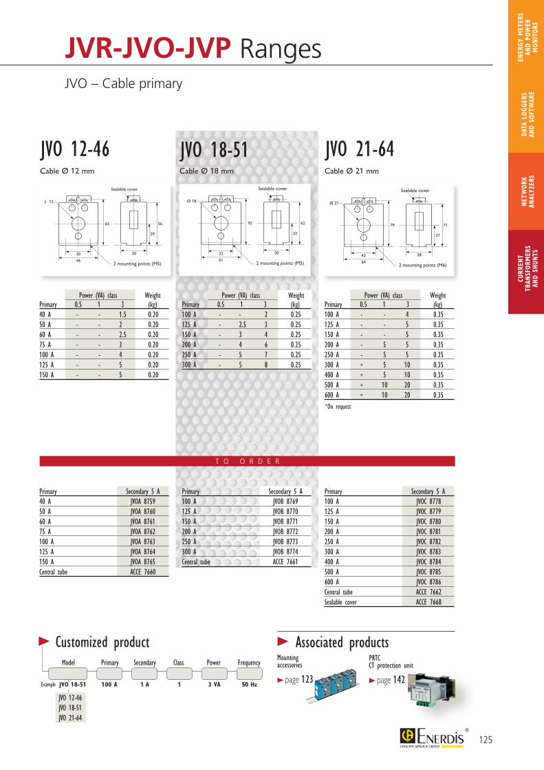
125
CURR
ENT
TRAN
SFOR
MER
SAN
D SH
UNTS
NETW
ORK
ANAL
YZER
SDA
TA L
OGGE
RS
AND
SOFT
WAR
E
ENER
GY M
ETER
S AN
D PO
WER
M
ONIT
ORS
T O O R D E R
30
63 56
29
Sealable cover
2 mounting points (M5)
30
46
ÿ 12
32
70 62
32
Sealable cover
2 mounting points (M5)
30
51
Ø 18
42
79 71
37
Sealable cover
2 mounting points (M6)
38
64
Ø 21
Power (VA) class WeightPrimary 0.5 1 3 (kg)40 A - - 1.5 0.2050 A - - 2 0.2060 A - - 2.5 0.2075 A - - 3 0.20100 A - - 4 0.20125 A - - 5 0.20150 A - - 5 0.20
Power (VA) class WeightPrimary 0.5 1 3 (kg)100 A - - 2 0.25125 A - 2.5 3 0.25150 A - 3 4 0.25200 A - 4 6 0.25250 A - 5 7 0.25300 A - 5 8 0.25
Power (VA) class WeightPrimary 0.5 1 3 (kg)100 A - - 4 0.35125 A - - 5 0.35150 A - - 5 0.35200 A - 5 5 0.35250 A - 5 5 0.35300 A * 5 10 0.35400 A * 5 10 0.35500 A * 10 20 0.35600 A * 10 20 0.35
Cable Ø 12 mm
JVO 12-46Cable Ø 18 mm Cable Ø 21 mm
JVO 18-51 JVO 21-64
Primary Secondary 5 A40 A JVOA 875950 A JVOA 876060 A JVOA 876175 A JVOA 8762100 A JVOA 8763125 A JVOA 8764150 A JVOA 8765Central tube ACCE 7660
Primary Secondary 5 A100 A JVOB 8769125 A JVOB 8770150 A JVOB 8771200 A JVOB 8772250 A JVOB 8773300 A JVOB 8774Central tube ACCE 7661
Primary Secondary 5 A100 A JVOC 8778125 A JVOC 8779150 A JVOC 8780200 A JVOC 8781250 A JVOC 8782300 A JVOC 8783400 A JVOC 8784500 A JVOC 8785600 A JVOC 8786Central tube ACCE 7662Sealable cover ACCE 7668
JVR-JVO-JVP Ranges JVO – Cable primary
*On request
Model Primary Secondary Class Power Frequency
JVO 12-46 JVO 18-51 JVO 21-64
JVO 18-51 100 A 1 3 VA 50 Hz1 A
> Customized product
Example
> Associated productsMounting accessories
> page 123
PRTCCT protection unit
> page 142
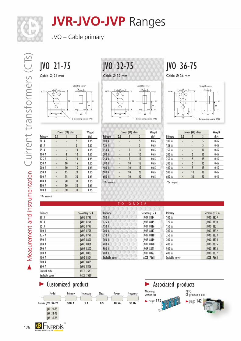
126
> M
easu
rem
ent
and
inst
rum
enta
tion C
urre
nt t
rans
form
ers
(CTs
)
T O O R D E R
JVR-JVO-JVP Ranges JVO – Cable primary
45
93 85
44
Sealable cover
2 mounting points (M6)
45
75
ÿ 21
45
93 85
44
Sealable cover
2 mounting points (M6)
45
75
Ø 32
45
93 85
44
Sealable cover
2 mounting points (M6)
45
75
Ø 36
Cable Ø 21 mm
Power (VA) class WeightPrimary 0.5 1 3 (kg)50 A - - 5 0.6560 A - - 5 0.6575 A - - 10 0.65100 A - 4 10 0.65125 A - 5 10 0.65150 A * 10 15 0.65200 A * 10 15 0.65250 A * 15 20 0.65300 A * 15 20 0.65400 A * 20 30 0.65500 A * 30 30 0.65600 A * 30 30 0.65
Power (VA) class WeightPrimary 0.5 1 3 (kg)100 A - - 5 0.65125 A - - 5 0.65150 A - 5 10 0.65200 A - 5 10 0.65250 A * 5 15 0.65300 A * 10 15 0.65400 A * 10 15 0.65500 A * 10 20 0.65600 A * 10 20 0.65
Power (VA) class WeightPrimary 0.5 1 3 (kg)100 A - - 5 0.45125 A - - 5 0.45150 A - - 10 0.45200 A - 5 10 0.45250 A * 5 15 0.45300 A * 5 15 0.45400 A * 5 15 0.45500 A * 10 20 0.45600 A * 20 20 0.45
JVO 21-75Cable Ø 32 mm Cable Ø 36 mm
JVO 32-75 JVO 36-75
Primary Secondary 5 A50 A JVOE 879560 A JVOE 879675 A JVOE 8797100 A JVOE 8798125 A JVOE 8799150 A JVOE 8800200 A JVOE 8801250 A JVOE 8802300 A JVOE 8803400 A JVOE 8804500 A JVOE 8805600 A JVOE 8806Central tube ACCE 7663Sealable cover ACCE 7668
Primary Secondary 5 A100 A JVOF 8814125 A JVOF 8815150 A JVOF 8816200 A JVOF 8817250 A JVOF 8818300 A JVOF 8819400 A JVOF 8820500 A JVOF 8821600 A JVOF 8822Sealable cover ACCE 7668
Primary Secondary 5 A100 A JVOG 8829125 A JVOG 8830150 A JVOG 8831200 A JVOG 8832250 A JVOG 8833300 A JVOG 8834400 A JVOG 8835500 A JVOG 8836600 A JVOG 8837Sealable cover ACCE 7668
*On request
*On request *On request
Model Primary Secondary Class Power Frequency
JVR 21-75 JVR 32-75 JVR 36-75
JVR 32-75 500 A 0.5 10 VA 50 Hz1 A
> Customized product
Example
> Associated productsMounting accessories
> page 123
PRTCCT protection unit
> page 142
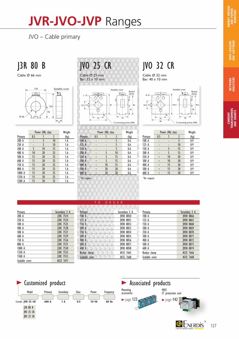
127
CURR
ENT
TRAN
SFOR
MER
SAN
D SH
UNTS
NETW
ORK
ANAL
YZER
SDA
TA L
OGGE
RS
AND
SOFT
WAR
E
ENER
GY M
ETER
S AN
D PO
WER
M
ONIT
ORS
T O O R D E R
154
Ø 66
42
134 Sealable cover
76
75
9332,5 85
44
Sealable cover
2 mounting points (M6)
Busbar clamp
45
ÿ 25
10,5
56
104,540,5 96,5
50
Sealable cover
2 mounting points (M6)
58
86
Ø 32
10,5
Busbar clamp
J3R 80 BCable Ø 66 mm
JVO 25 CR JVO 32 CRCable Ø 25 mmBar: 32 x 10 mm
Cable Ø 32 mmBar: 40 x 10 mm
Power (VA) class WeightPrimary 0.5 1 3 (kg)200 A - 5 10 1.6250 A - 5 10 1.6300 A 5 10 15 1.6400 A 10 20 25 1.6500 A 15 20 25 1.6600 A 15 20 25 1.6750 A 15 20 25 1.6800 A 15 20 25 1.61000 A 15 20 25 1.61250 A 15 20 25 1.61500 A 15 20 25 1.6
Power (VA) class WeightPrimary 0.5 1 3 (kg)100 A - - 5 0.6125 A - - 5 0.6150 A - - 5 0.6200 A - 5 10 0.6250 A * 5 15 0.6300 A * 5 15 0.6400 A * 10 15 0.6500 A * 20 20 0.6600 A * 20 20 0.6
Power (VA) class WeightPrimary 0.5 1 3 (kg)100 A - - 5 0.9125 A - - 10 0.9150 A - 5 15 0.9200 A - 5 15 0.9250 A * 10 20 0.9300 A * 10 30 0.9400 A * 15 30 0.9500 A * 15 30 0.9600 A * 15 30 0.9
Primary Secondary 5 A200 A J3RC 7514250 A J3RC 7524300 A J3RC 7525400 A J3RC 7528500 A J3RC 7527600 A J3RC 7529750 A J3RC 7526800 A J3RC 75311000 A J3RC 75301250 A J3RC 75321500 A J3RC 7533Sealable cover ACCE 7671
Primary Secondary 5 A100 A JVOD 8850125 A JVOD 8851150 A JVOD 8852200 A JVOD 8853250 A JVOD 8854300 A JVOD 8855400 A JVOD 8856500 A JVOD 8857600 A JVOD 8858Busbar clamp ACCE 7665Sealable cover ACCE 7668
Primary Secondary 5 A100 A JVOH 8866125 A JVOH 8867150 A JVOH 8868200 A JVOH 8869250 A JVOH 8870300 A JVOH 8871400 A JVOH 8872500 A JVOH 8873600 A JVOH 8874Busbar clamp ACCE 7666Sealable cover ACCE 7668
*On request*On request
JVR-JVO-JVP Ranges JVO – Cable primary
Model Primary Secondary Class Power Frequency
J3R 80 B JVO 25 CRJVO 32 CR
JVR 25 CR 600 A 0.5 10 VA 60 Hz1 A
> Customized product
Example
> Associated productsMounting accessories
> page 123
PRTCCT protection unit
> page 142
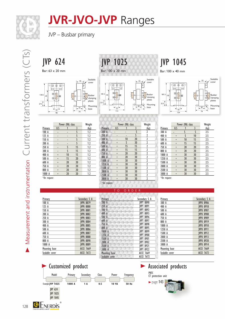
JVR-JVO-JVP Ranges JVP – Busbar primary
T O O R D E R
Primary Secondary 5 A100 A JVPR 8879125 A JVPR 8880150 A JVPR 8881200 A JVPR 8882250 A JVPR 8883300 A JVPR 8884400 A JVPR 8885500 A JVPR 8886600 A JVPR 8887750 A JVPR 8888800 A JVPR 88901000 A JVPR 8889Mounting base ACCE 7669Sealable cover ACCE 7672
Primary Secondary 5 A200 A JVPT 8890250 A JVPT 8891300 A JVPT 8892400 A JVPT 8893500 A JVPT 8896600 A JVPT 8897750 A JVPT 8898800 A JVPT 88951000 A JVPT 88991250 A JVPT 89001500 A JVPT 89012000 A JVPT 89022500 A JVPT 89213000 A JVPT 8922Mounting base ACCE 7669Sealable cover ACCE 7672
Primary Secondary 5 A300 A JVPU 8906400 A JVPU 8918500 A JVPU 8907600 A JVPU 8908750 A JVPU 8909800 A JVPU 89191000 A JVPU 89101250 A JVPU 89111500 A JVPU 89122000 A JVPU 89132500 A JVPU 89203000 A JVPU 8914Mounting base ACCE 7669Sealable cover ACCE 7672
2274
35
42
98
65130.5
27.5
Sealable cover
Busbar clamping plates
Mounting base 22
74
45
52
114
105181.5
32.5
Sealable cover
Busbar clamping plates
Mounting base
4274
45
52
134
105181.5
32.5
Sealable cover
Busbar clamping plates
Mounting base
Bar: 100 x 20 mm
JVP 1025 JVP 1045Bar: 100 x 40 mm
JVP 624Bar: 63 x 20 mm
Power (VA) class WeightPrimary 0.5 1 3 (kg)200 A - - 5 2250 A - - 5 2300 A - 10 20 2400 A * 5 30 2500 A * 15 15 2600 A * 15 15 2750 A * 20 20 2800 A * 20 30 21000 A * 30 30 21250 A * 30 30 21500 A * 30 30 22000 A * 30 30 22500 A * 30 30 23000 A * 30 30 2
Power (VA) class WeightPrimary 0.5 1 3 (kg)300 A - 5 5 2.5400 A * 5 10 2.5500 A * 10 15 2.5600 A * 15 15 2.5750 A * 20 20 2.5800 A * 20 20 2.51000 A * 30 30 2.51250 A * 30 30 2.51500 A * 30 30 2.52000 A * 30 30 2.52500 A * 30 30 2.53000 A * 30 30 2.5
Power (VA) class WeightPrimary 0.5 1 3 (kg)100 A - - 5 1.2125 A - - 5 1.2150 A - - 5 1.2200 A - - 5 1.2250 A - 5 15 1.2300 A - 5 15 1.2400 A * 10 15 1.2500 A * 15 20 1.2600 A * 20 20 1.2750 A * 20 20 1.2800 A * 20 20 1.21000 A * 20 20 1.2*On request
*On request
*On request
Model Primary Secondary Class Power Frequency
JVP 624 JVP 1025 JVP 1045
JVP 1025 1000 A 0.5 10 VA 50 Hz1 A
> Customized product
Example
> Associated productsPRTCCT protection unit
> page 143
128
> M
easu
rem
ent
and
inst
rum
enta
tion C
urre
nt t
rans
form
ers
(CTs
)
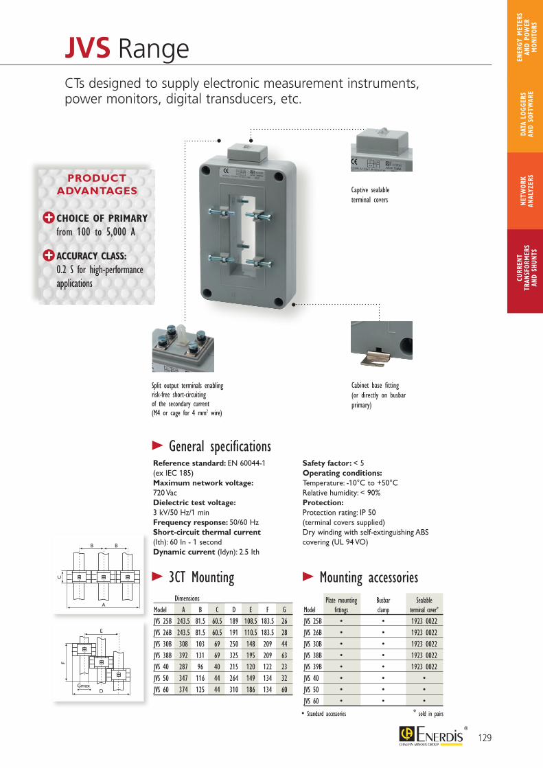
B
C F
B E
A DGmax
B
C F
B E
A DGmax
> 3CT Mounting > Mounting accessories
Split output terminals enabling risk-free short-circuiting of the secondary current (M4 or cage for 4 mm2 wire)
Captive sealable terminal covers
Cabinet base fitting(or directly on busbar primary)
Dimensions Model A B C D E F GJVS 25B 243.5 81.5 60.5 189 108.5 183.5 26JVS 26B 243.5 81.5 60.5 191 110.5 183.5 28JVS 30B 308 103 69 250 148 209 44JVS 38B 392 131 69 325 195 209 63JVS 40 287 96 40 215 120 122 23JVS 50 347 116 44 264 149 134 32JVS 60 374 125 44 310 186 134 60
Reference standard: EN 60044-1 (ex IEC 185)Maximum network voltage:720 VacDielectric test voltage:3 kV/50 Hz/1 minFrequency response: 50/60 HzShort-circuit thermal current(Ith): 60 In - 1 secondDynamic current (Idyn): 2.5 Ith
Safety factor: < 5Operating conditions: Temperature: -10°C to +50°CRelative humidity: < 90% Protection:Protection rating: IP 50 (terminal covers supplied)Dry winding with self-extinguishing ABScovering (UL 94 VO)
> General specifications
Plate mounting Busbar Sealable Model fittings clamp terminal cover*JVS 25B • • 1923 0022JVS 26B • • 1923 0022JVS 30B • • 1923 0022JVS 38B • • 1923 0022JVS 39B • • 1923 0022JVS 40 • • •JVS 50 • • •JVS 60 • • •
• Standard accessories * sold in pairs
JVS RangeCTs designed to supply electronic measurement instruments, power monitors, digital transducers, etc.
PRODUCT ADVANTAGES
CHOICE OF PRIMARY from 100 to 5,000 A
ACCURACY CLASS: 0.2 S for high-performance applications
129
CURR
ENT
TRAN
SFOR
MER
SAN
D SH
UNTS
NETW
ORK
ANAL
YZER
SDA
TA L
OGGE
RS
AND
SOFT
WAR
E
ENER
GY M
ETER
S AN
D PO
WER
M
ONIT
ORS
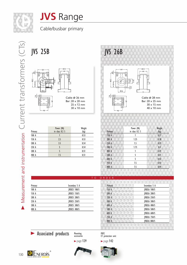
T O O R D E R
Power (VA) Weight Primary in class 0.2 S (kg)100 A 1 0.53150 A 2.5 0.53200 A 3.5 0.54250 A 5 0.54300 A 5 0.51400 A 7.5 0.51
Power (VA) Weight Primary in class 0.2 S (kg)150 A 1 0.37200 A 1.25 0.38250 A 1.5 0.39300 A 1.75 0.4400 A 1 0.41500 A 5 0.41600 A 5 0.42750 A 7.5 0.43800 A 7.5 0.44
Primary Secondary 5 A150 A JVSB26 100/5200 A JVSB26 200/5250 A JVSB26 250/5300 A JVSB26 300/5400 A JVSB26 400/5500 A JVSB26 500/5600 A JVSB26 600/5750 A JVSB26 750/5 800 A JVSB26 800/5
Primary Secondary 5 A100 A JVSB25 100/5150 A JVSB25 150/5200 A JVSB25 200/5250 A JVSB25 250/5300 A JVSB25 300/5400 A JVSB25 400/5
JVS RangeCable/busbar primary
40.6
64
80.5
34
25.22.5
4.5
28,5
60.544
71
5.6
60
46
P1
S2
P2
S1
10.6
40.6
64
80.5
34
25.22.5
4.5
28,5
60.544
71
5.6
60
46
P1
S2
P2
S1
10.6
30.6
64
80.5
344.
5
20.62.5
60.544
71
5.6
6046
P1
S2
P2
S1
26
10.6
30.6
64
80.5
344.
5
20.62.5
60.544
71
5.6
60
46
P1
S2
P2
S1
26
10.6
Cable ø 26 mm Bar: 20 x 20 mm
25 x 12 mm 30 x 10 mm
JVS 25B
Cable ø 28 mm Bar: 20 x 25 mm
30 x 15 mm 40 x 10 mm
JVS 26B
PRTC CT protection unit
> page 142
Mounting accessories
> page 129
> Associated products
130
> M
easu
rem
ent
and
inst
rum
enta
tion C
urre
nt t
rans
form
ers
(CTs
)
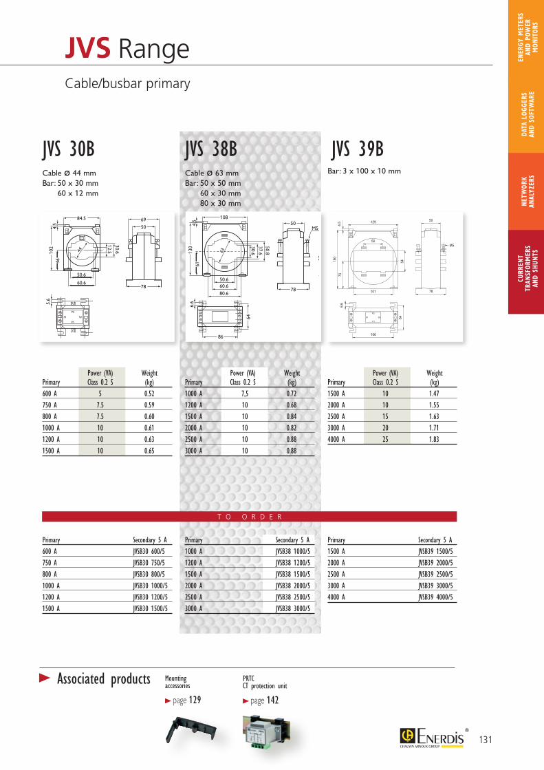
131
CURR
ENT
TRAN
SFOR
MER
SAN
D SH
UNTS
NETW
ORK
ANAL
YZER
SDA
TA L
OGGE
RS
AND
SOFT
WAR
E
ENER
GY M
ETER
S AN
D PO
WER
M
ONIT
ORS
JVS RangeCable/busbar primary
Power (VA) WeightPrimary Class 0.2 S (kg)600 A 5 0.52750 A 7.5 0.59800 A 7.5 0.601000 A 10 0.611200 A 10 0.631500 A 10 0.65
Power (VA) WeightPrimary Class 0.2 S (kg)1000 A 7,5 0.721200 A 10 0.681500 A 10 0.842000 A 10 0.822500 A 10 0.883000 A 10 0.88
Power (VA) WeightPrimary Class 0.2 S (kg)1500 A 10 1.472000 A 10 1.552500 A 15 1.633000 A 20 1.714000 A 25 1.83
Primary Secondary 5 A600 A JVSB30 600/5750 A JVSB30 750/5800 A JVSB30 800/51000 A JVSB30 1000/51200 A JVSB30 1200/51500 A JVSB30 1500/5
Primary Secondary 5 A1500 A JVSB39 1500/52000 A JVSB39 2000/52500 A JVSB39 2500/53000 A JVSB39 3000/54000 A JVSB39 4000/5
Cable ø 44 mm Bar: 50 x 30 mm
60 x 12 mm
JVS 30BCable ø 63 mm Bar: 50 x 50 mm
60 x 30 mm 80 x 30 mm
Bar: 3 x 100 x 10 mm
JVS 38B JVS 39B
50.6
60.6
84.5
102
46
30.6
12.544
4.5
69
50
78
5.6
60
P1
S2
P2
S1
50.6
60.6
84.5
102
46
30.6
12.544
4.5
69
50
78
5.6
60
P1
S2
P2
S1
50.6
80.660.6
108
130
86
61
50.837.630.6
4.5 50
78
M5 6.6
64
63
50.6
80.6
60.6
108
130
86
61
50.837.630.6
4.5
50 78
M5
6.6
64
63
T O O R D E R
Primary Secondary 5 A1000 A JVSB38 1000/51200 A JVSB38 1200/51500 A JVSB38 1500/52000 A JVSB38 2000/52500 A JVSB38 2500/53000 A JVSB38 3000/5
704.5
150
50
78
P2
P1
S2S1
129
6.6
106
64
101
54
50M5
PRTC CT protection unit
> page 142
Mounting accessories
> page 129
> Associated products
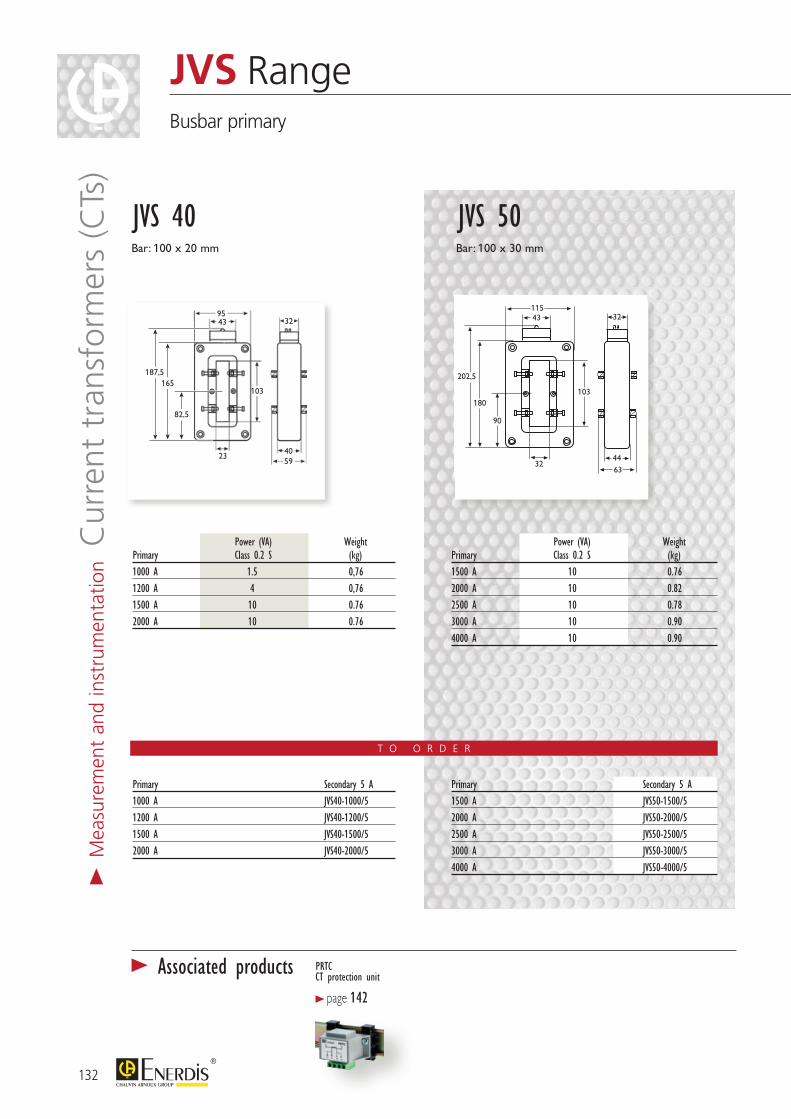
132
> M
easu
rem
ent
and
inst
rum
enta
tion C
urre
nt t
rans
form
ers
(CTs
)JVS RangeBusbar primary
PRTC CT protection unit
> page 142
> Associated products
Power (VA) Weight Primary Class 0.2 S (kg)1000 A 1.5 0,761200 A 4 0,761500 A 10 0.762000 A 10 0.76
Power (VA) Weight Primary Class 0.2 S (kg)1500 A 10 0.762000 A 10 0.822500 A 10 0.783000 A 10 0.904000 A 10 0.90
Primary Secondary 5 A1000 A JVS40-1000/51200 A JVS40-1200/51500 A JVS40-1500/52000 A JVS40-2000/5
Primary Secondary 5 A1500 A JVS50-1500/52000 A JVS50-2000/52500 A JVS50-2500/53000 A JVS50-3000/54000 A JVS50-4000/5
95
187,5165
82,5
103
5940
43
23
32
115
202,5
180
90
103
6344
43
32
32
Bar: 100 x 20 mm
JVS 40Bar: 100 x 30 mm
JVS 50
T O O R D E R
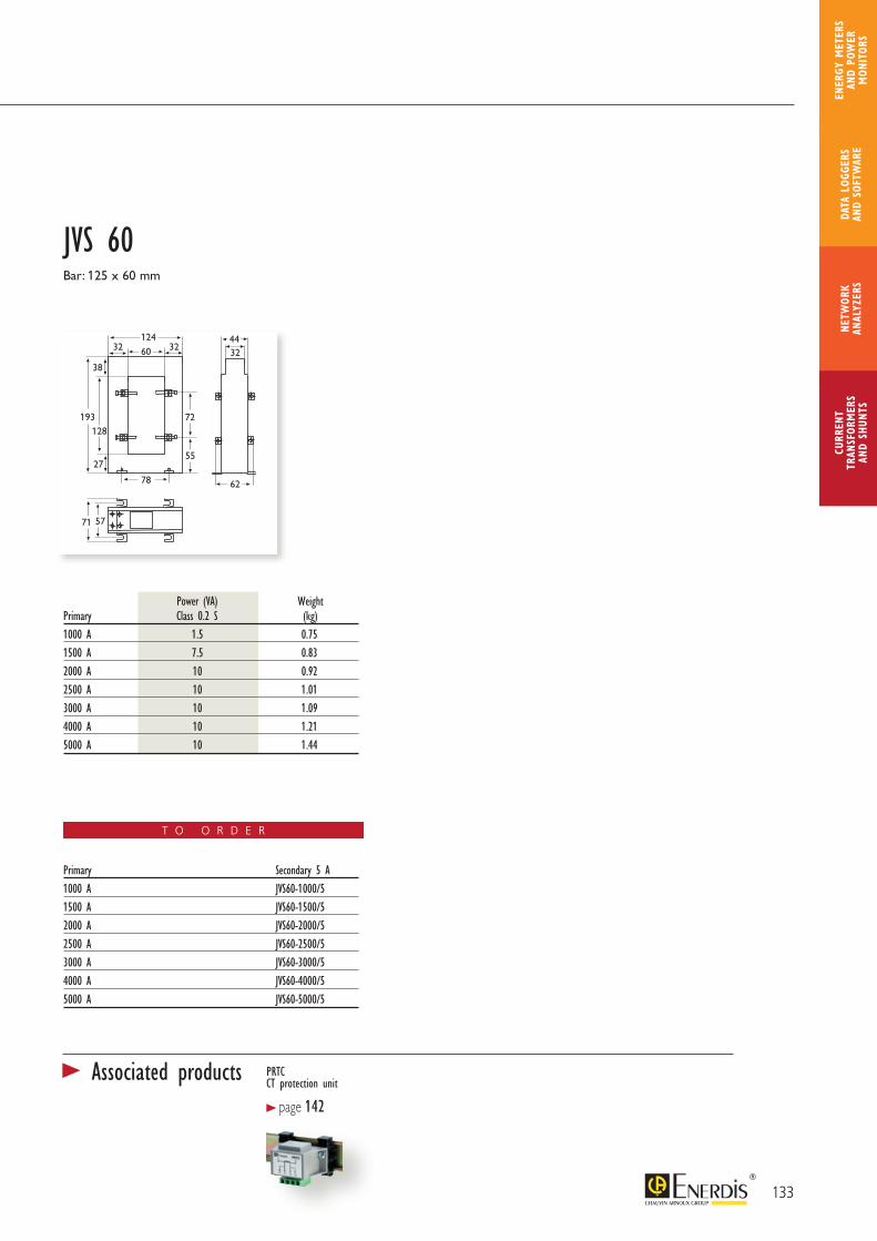
Power (VA) Weight Primary Class 0.2 S (kg)1000 A 1.5 0.751500 A 7.5 0.832000 A 10 0.922500 A 10 1.013000 A 10 1.094000 A 10 1.215000 A 10 1.44
Primary Secondary 5 A1000 A JVS60-1000/51500 A JVS60-1500/52000 A JVS60-2000/52500 A JVS60-2500/53000 A JVS60-3000/54000 A JVS60-4000/55000 A JVS60-5000/5
124 4432
3232
38
60
78
72
71
62
57
5527
193128
Bar: 125 x 60 mm
JVS 60
T O O R D E R
133
CURR
ENT
TRAN
SFOR
MER
SAN
D SH
UNTS
NETW
ORK
ANAL
YZER
SDA
TA L
OGGE
RS
AND
SOFT
WAR
E
ENER
GY M
ETER
S AN
D PO
WER
M
ONIT
ORS
PRTC CT protection unit
> page 142
> Associated products

134
> M
easu
rem
ent
and
inst
rum
enta
tion C
urre
nt t
rans
form
ers
(CTs
)Single-phase, single-rating: JVP1045 BTransformers for tariff metering
42 Fixingplate
Bar-tighteningplates
74
65
45
134
105
32,5
181,
5
Sealablecover
Busbar 100 x 40 mm
Power (VA) in class 0.5 Weight 7.5 15 (kg)Primary Secondary 5 A500 A JVPA 7569 2.501000 A JVPA 7573 2.50 2000 A JVPA 7576 2.50 500-1000 A* JVPA 7589 JVPA 7585 2.50 1000-2000 A** JVPA 7590 JVPA 7588 2.50
> General specificationsReference standard: EN 60044-1 (ex-IEC 185) and NFC 42-502Maximum network voltage: 720 VacDielectric test voltage: 3 kV/50 Hz/1 minFrequency response: 50/60 HzThermal short-circuit current (Ith) : 80 InDynamic current (Idyn): 2.5 Ith
Safety factor: 10 in class 0.5 Except * SF = 6.4/10.5 and **SF = 4.7/8.2Operating conditions:Temperature: -20°C to +60°CRelative humidity: 93% to 40°CProtection: Protection rating: IP 50 Dry winding in self-extinguishing ABS envelope (UL 94 VO)
DELIVERED WITH SEALABLE PROTECTIVE COVER
for the secondary. Simple M5 terminals
DIRECT MOUNTING on primary busbar by means of plate and tightening screw or panel mounting with mounting plate
T O O R D E R
Busbar primary
JVP1045 B
PRODUCT ADVANTAGES
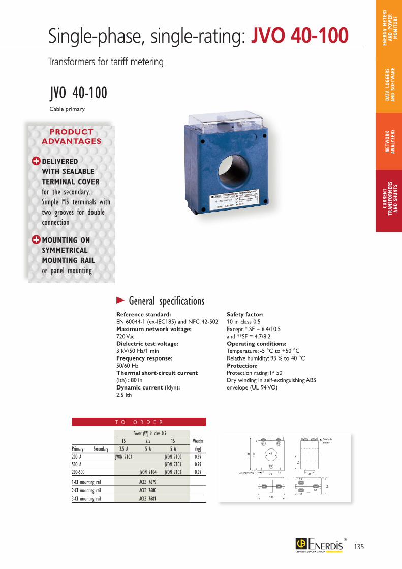
135
CURR
ENT
TRAN
SFOR
MER
SAN
D SH
UNTS
NETW
ORK
ANAL
YZER
SDA
TA L
OGGE
RS
AND
SOFT
WAR
E
ENER
GY M
ETER
S AN
D PO
WER
M
ONIT
ORS
100
70
125
110
56
66
42
S1
S1
S2
S2
S3
P1
36
Sealable cover
2 screws M6
> General specificationsReference standard: EN 60044-1 (ex-IEC185) and NFC 42-502Maximum network voltage: 720 VacDielectric test voltage: 3 kV/50 Hz/1 minFrequency response: 50/60 HzThermal short-circuit current (Ith) : 80 InDynamic current (Idyn): 2.5 Ith
Safety factor: 10 in class 0.5 Except * SF = 6.4/10.5 and **SF = 4.7/8.2Operating conditions:Temperature: -5 °C to +50 °CRelative humidity: 93 % to 40 °CProtection: Protection rating: IP 50 Dry winding in self-extinguishing ABS envelope (UL 94 VO)
DELIVERED WITH SEALABLE TERMINAL COVER for the secondary. Simple M5 terminals with two grooves for double connection
MOUNTING ON SYMMETRICAL MOUNTING RAIL or panel mounting
Power (VA) in class 0.5 15 7.5 15 WeightPrimary Secondary 2.5 A 5 A 5 A (kg)200 A JVON 7103 JVON 7100 0.97500 A JVON 7101 0.97200-500 JVON 7104 JVON 7102 0.97
1-CT mounting rail ACCE 7679 2-CT mounting rail ACCE 7680 3-CT mounting rail ACCE 7681
T O O R D E R
Cable primary
JVO 40-100
Single-phase, single-rating: JVO 40-100Transformers for tariff metering
PRODUCT ADVANTAGES
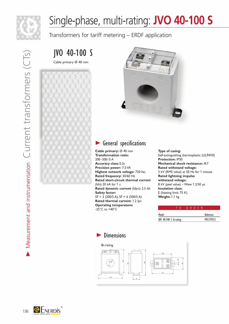
136
> M
easu
rem
ent
and
inst
rum
enta
tion C
urre
nt t
rans
form
ers
(CTs
)Single-phase, multi-rating: JVO 40-100 STransformers for tariff metering – ERDF application
> General specificationsCable primary: Ø 40 mmTransformation ratio: 200 - 500 / 5 AAccuracy class: 0.2sPrecision power: 7.5 VAHighest network voltage: 720 VacRated frequency: 50/60 HzRated short-circuit thermal current (Ith): 20 kA for 1 sRated dynamic current (Idyn): 2.5 IthSafety factor: SF = 3 (200/5 A); SF = 6 (500/5 A)Rated thermal current: 1.2 IpnOperating temperature: -25°C to +40°C
Type of casing: Self-extinguishing thermoplastic (UL94V0)Protection: IP30Mechanical shock resistance: IK7Rated withstand voltage: 3 kV (RMS value) at 50 Hz for 1 minuteRated lightning impulse withstand voltage:8 kV (peal value) – Wave 1.2/50 μsInsulation class:E (heating limit: 75 K)Weight: 1.1 kg
PRODUCT ADVANTAGES
Cable primary Ø 40 mm
JVO 40-100 S
CLASS 0.2s ACCORDING TO IEC 60044-1 Particularly SUITABLE FOR ERDF-QUALIFIED BI-RATING AND TRI-RATING ELECTRONIC METERS
Bi-rating
> Dimensions
Model ReferenceJVO 40-100 S bi-rating P01379512
T O O R D E R
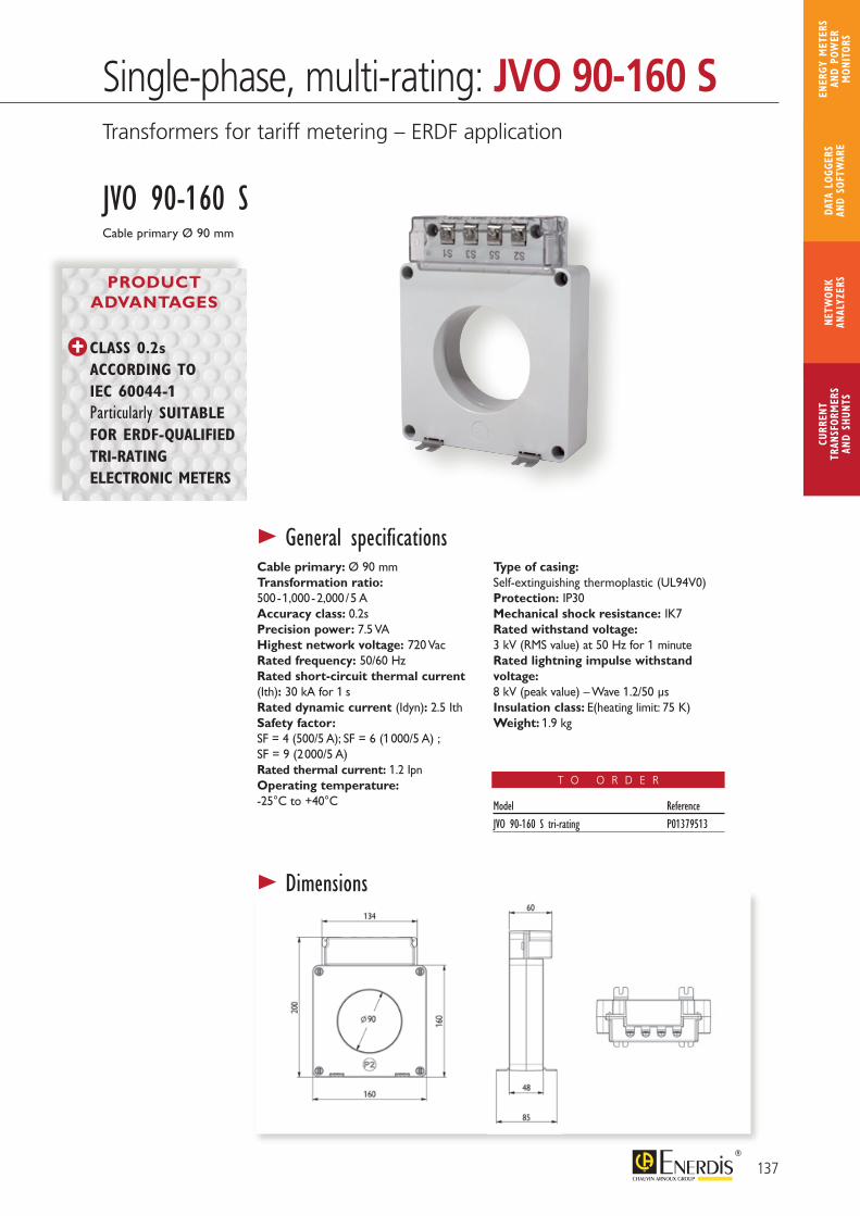
Single-phase, multi-rating: JVO 90-160 STransformers for tariff metering – ERDF application
> General specifications
> Dimensions
PRODUCT ADVANTAGES
Cable primary Ø 90 mm
JVO 90-160 S
CLASS 0.2s ACCORDING TO IEC 60044-1 Particularly SUITABLE FOR ERDF-QUALIFIED TRI-RATING ELECTRONIC METERS
Cable primary: Ø 90 mmTransformation ratio: 500 - 1,000 - 2,000 / 5 AAccuracy class: 0.2sPrecision power: 7.5 VAHighest network voltage: 720 VacRated frequency: 50/60 HzRated short-circuit thermal current (Ith): 30 kA for 1 sRated dynamic current (Idyn): 2.5 IthSafety factor: SF = 4 (500/5 A); SF = 6 (1 000/5 A) ;SF = 9 (2 000/5 A)Rated thermal current: 1.2 IpnOperating temperature: -25°C to +40°C
Type of casing: Self-extinguishing thermoplastic (UL94V0)Protection: IP30Mechanical shock resistance: IK7Rated withstand voltage: 3 kV (RMS value) at 50 Hz for 1 minuteRated lightning impulse withstand voltage: 8 kV (peak value) – Wave 1.2/50 μsInsulation class: E(heating limit: 75 K)Weight: 1.9 kg
Model ReferenceJVO 90-160 S tri-rating P01379513
T O O R D E R
137
CURR
ENT
TRAN
SFOR
MER
SAN
D SH
UNTS
NETW
ORK
ANAL
YZER
SDA
TA L
OGGE
RS
AND
SOFT
WAR
E
ENER
GY M
ETER
S AN
D PO
WER
M
ONIT
ORS
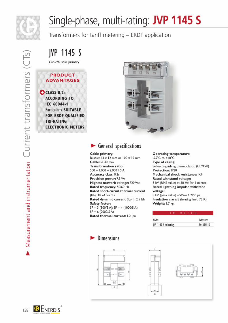
> General specificationsCable primary:Busbar: 63 x 12 mm or 100 x 12 mmCable: Ø 40 mmTransformation ratio:500 – 1,000 – 2,000 / 5 AAccuracy class: 0.2sPrecision power: 7.5 VAHighest network voltage: 720 VacRated frequency: 50/60 HzRated short-circuit thermal current (Ith): 30 kA for 1 sRated dynamic current (Idyn): 2.5 IthSafety factor:SF = 3 (500/5 A); SF = 4 (1000/5 A);SF = 6 (2000/5 A)Rated thermal current: 1.2 Ipn
Operating temperature:-25°C to +40°CType of casing:Self-extinguishing thermoplastic (UL94V0)Protection: IP30Mechanical shock resistance: IK7Rated withstand voltage:3 kV (RMS value) at 50 Hz for 1 minuteRated lightning impulse withstand voltage:8 kV (peak value) – Wave 1.2/50 μsInsulation class: E (heating limit: 75 K)Weight: 1.7 kg
PRODUCT ADVANTAGES
Cable/busbar primary
JVP 1145 S
CLASS 0.2s ACCORDING TO IEC 60044-1 Particularly SUITABLE FOR ERDF-QUALIFIED TRI-RATING ELECTRONIC METERS
> Dimensions
Model ReferenceJVP 1145 S tri-rating P01379510
T O O R D E R
> M
easu
rem
ent
and
inst
rum
enta
tion C
urre
nt t
rans
form
ers
(CTs
)
138
Single-phase, multi-rating: JVP 1145 STransformers for tariff metering – ERDF application
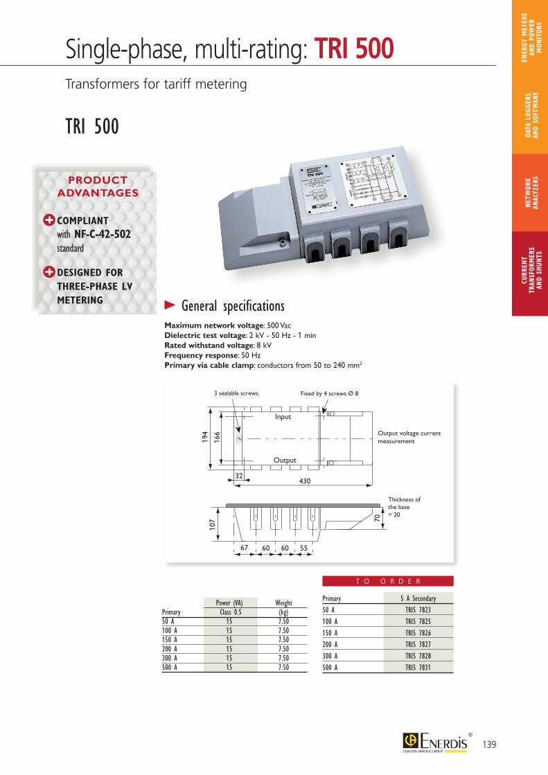
TRI 500
166
70
107
3 sealable screws Fixed by 4 screws Ø 8
Output voltage current measurement
Thickness ofthe base = 20
194
Output
67 60 60
43032
55
Input
> General specificationsMaximum network voltage: 500 VacDielectric test voltage: 2 kV - 50 Hz - 1 minRated withstand voltage: 8 kVFrequency response: 50 HzPrimary via cable clamp: conductors from 50 to 240 mm2
Power (VA) WeightPrimary Class 0.5 (kg)50 A 15 7.50100 A 15 7.50150 A 15 7.50200 A 15 7.50300 A 15 7.50500 A 15 7.50
COMPLIANT
with NF-C-42-502 standard
DESIGNED FOR THREE-PHASE LV METERING
PRODUCT ADVANTAGES
Primary 5 A Secondary50 A TRI5 7823100 A TRI5 7825150 A TRI5 7826200 A TRI5 7827300 A TRI5 7828500 A TRI5 7831
T O O R D E R
139
CURR
ENT
TRAN
SFOR
MER
SAN
D SH
UNTS
NETW
ORK
ANAL
YZER
SDA
TA L
OGGE
RS
AND
SOFT
WAR
E
ENER
GY M
ETER
S AN
D PO
WER
M
ONIT
ORS
Single-phase, multi-rating: TRI 500Transformers for tariff metering
Single-phase, multi-rating: JVP 1145 STransformers for tariff metering – ERDF application
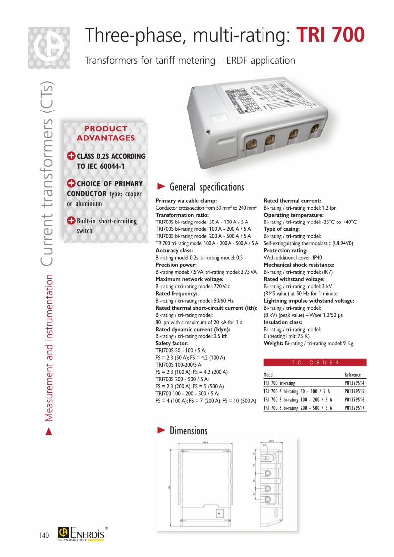
140
Three-phase, multi-rating: TRI 700Transformers for tariff metering – ERDF application
> M
easu
rem
ent
and
inst
rum
enta
tion C
urre
nt t
rans
form
ers
(CTs
)
CLASS 0.2S ACCORDING TO IEC 60044-1
CHOICE OF PRIMARY CONDUCTOR type: copper or aluminium
Built-in short-circuiting switch
> General specificationsPrimary via cable clamp: Conductor cross-section from 50 mm² to 240 mm²Transformation ratio:TRI700S bi-rating model 50 A - 100 A / 5 ATRI700S bi-rating model 100 A - 200 A / 5 ATRI700S bi-rating model 200 A - 500 A / 5 ATRI700 tri-rating model 100 A - 200 A - 500 A / 5 AAccuracy class: Bi-rating model 0.2s; tri-rating model: 0.5Precision power:Bi-rating model: 7.5 VA; tri-rating model: 3.75 VAMaximum network voltage: Bi-rating / tri-rating model: 720 VacRated frequency: Bi-rating / tri-rating model: 50/60 HzRated thermal short-circuit current (Ith): Bi-rating / tri-rating model: 80 Ipn with a maximum of 20 kA for 1 sRated dynamic current (Idyn): Bi-rating / tri-rating model: 2.5 IthSafety factor:TRI700S 50 - 100 / 5 A:FS = 2.3 (50 A); FS = 4.2 (100 A)TRI700S 100-200/5 A:FS = 2.3 (100 A); FS = 4.2 (200 A)TRI700S 200 - 500 / 5 A:FS = 2,3 (200 A); FS = 5 (500 A)TRI700 100 - 200 - 500 / 5 A:FS = 4 (100 A); FS = 7 (200 A); FS = 10 (500 A)
Rated thermal current: Bi-rating / tri-rating model: 1.2 IpnOperating temperature: Bi-rating / tri-rating model: -25°C to +40°CType of casing:Bi-rating / tri-rating model: Self-extinguishing thermoplastic (UL94V0)Protection rating: With additional cover: IP40Mechanical shock resistance: Bi-rating / tri-rating model: (IK7)Rated withstand voltage:Bi-rating / tri-rating model: 3 kV(RMS value) at 50 Hz for 1 minuteLightning impulse withstand voltage:Bi-rating / tri-rating model: (8 kV) (peak value) – Wave 1.2/50 μsInsulation class:Bi-rating / tri-rating model: E (heating limit: 75 K)Weight: Bi-rating / tri-rating model: 9 Kg
> Dimensions
T O O R D E R
Model ReferenceTRI 700 tri-rating P01379514TRI 700 S bi-rating 50 - 100 / 5 A P01379515TRI 700 S bi-rating 100 - 200 / 5 A P01379516TRI 700 S bi-rating 200 - 500 / 5 A P01379517
PRODUCT ADVANTAGES
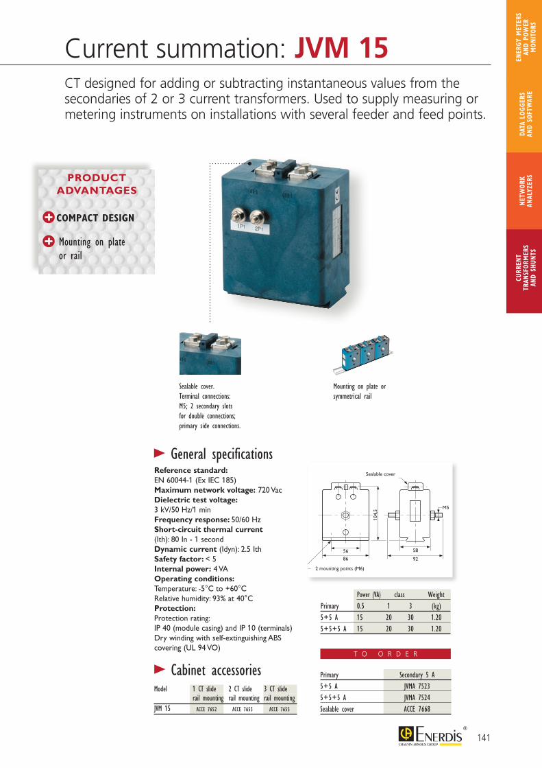
56
104,
5 M5
Sealable cover
2 mounting points (M6)
58
86 92
Sealable cover.Terminal connections: M5; 2 secondary slots for double connections; primary side connections.
Mounting on plate or symmetrical rail
> General specifications
Primary Secondary 5 A5+5 A JVMA 75235+5+5 A JVMA 7524Sealable cover ACCE 7668
Reference standard:EN 60044-1 (Ex IEC 185)Maximum network voltage: 720 VacDielectric test voltage:3 kV/50 Hz/1 minFrequency response: 50/60 HzShort-circuit thermal current(Ith): 80 In - 1 secondDynamic current (Idyn): 2.5 IthSafety factor: < 5Internal power: 4 VAOperating conditions:Temperature: -5°C to +60°CRelative humidity: 93% at 40°CProtection:Protection rating: IP 40 (module casing) and IP 10 (terminals)Dry winding with self-extinguishing ABS covering (UL 94 VO)
Power (VA) class WeightPrimary 0.5 1 3 (kg)5+5 A 15 20 30 1.205+5+5 A 15 20 30 1.20
> Cabinet accessories
ACCE 7652 ACCE 7653 ACCE 7655
Model 1 CT slide 2 CT slide 3 CT slide rail mounting rail mounting rail mountingJVM 15
Current summation: JVM 15CT designed for adding or subtracting instantaneous values from the secondaries of 2 or 3 current transformers. Used to supply measuring or metering instruments on installations with several feeder and feed points.
COMPACT DESIGN
Mounting on plate or rail
PRODUCT ADVANTAGES
T O O R D E R
141
CURR
ENT
TRAN
SFOR
MER
SAN
D SH
UNTS
NETW
ORK
ANAL
YZER
SDA
TA L
OGGE
RS
AND
SOFT
WAR
E
ENER
GY M
ETER
S AN
D PO
WER
M
ONIT
ORS
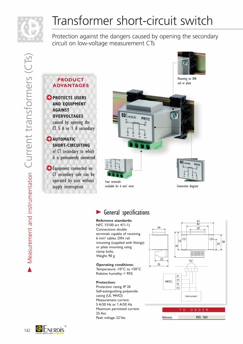
> M
easu
rem
ent
and
inst
rum
enta
tion C
urre
nt t
rans
form
ers
(CTs
)
142
PRTC
TC
S1
S'1
S2
S'2
Instrument
23
35
24
202833
47
294261
Mounting on DINrail or plate
Connection diagramFour terminals available for 6 mm2 wires
> General specifications
Reference PRTC 1001
Reference standards:NFC 15100 art 411-1)Connections: double terminals capable of receiving 6 mm2 cables. DIN rail mounting (supplied with fittings) or plate mounting using clamp bolts.Weight: 90 g
Operating conditions:Temperature: -10°C to +50°CRelative humidity: < 95%
Protection:Protection rating: IP 20 Self-extinguishing polyamide casing (UL 94VO)Measurement current: 5 A/50 Hz or 1 A/50 HzMaximum permitted current:25 AacPeak voltage: 22 Vac
Transformer short-circuit switchProtection against the dangers caused by opening the secondarycircuit on low-voltage measurement CTs
T O O R D E R
PROTECTS USERS AND EQUIPMENT AGAINST OVERVOLTAGES
caused by opening the CT 5 A or 1 A secondary
AUTOMATIC SHORT-CIRCUITING of CT secondary to which it is permanently connected
Equipment connected on CT secondary side can be operated by user without supply interruption
PRODUCT ADVANTAGES

Notes
143
CURR
ENT
TRAN
SFOR
MER
SAN
D SH
UNTS
NETW
ORK
ANAL
YZER
SDA
TA L
OGGE
RS
AND
SOFT
WAR
E
ENER
GY M
ETER
S AN
D PO
WER
M
ONIT
ORS
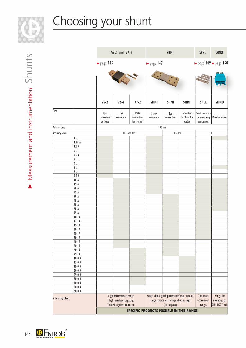
144144
> M
easu
rem
ent
and
inst
rum
enta
tion S
hunt
s
76-2 76-2 77-2 SHMI SHMI SHMI SHEL SHMO
Type Eye connection on base
Eye connection
Plate connection for busbar
Screw connection
Eye connection
Connection to block for
busbar
Direct connection to measuring component
Modular casing
Voltage drop 100 mV
Accuracy class 0.2 and 0.5 0.5 and 1 11 A1.25 A1.5 A2 A2.5 A3 A4 A5 A6 A7.5 A10 A15 A20 A25 A30 A40 A50 A60 A75 A100 A125 A150 A200 A250 A300 A400 A500 A600 A750 A1000 A1250 A1500 A2000 A2500 A3000 A4000 A5000 A6000 A
StrengthsHigh-performance range.High overload capacity.
Treated against corrosion.
Range with a good performance/price trade-off.Large choice of voltage drop ratings
(on request).
The most economical
range.
Range for mounting on
DIN 46277 rail.
SPECIFIC PRODUCTS POSSIBLE IN THIS RANGE
> page 145
SHMI76-2 and 77-2
> page 147
SHEL SHMO
> page 149> page 150
Choosing your shunt

145
CURR
ENT
TRAN
SFOR
MER
SAN
D SH
UNTS
NETW
ORK
ANAL
YZER
SDA
TA L
OGGE
RS
AND
SOFT
WAR
E
ENER
GY M
ETER
S AN
D PO
WER
M
ONIT
ORS
Large-area fittings to facilitate heat dissipation
> General specifications
Protection against corrosion with epoxy-modified acrylic paint
Accuracy class defined in the following domain:Over the whole measurement range, for an ambient temperature of:• -10°C to +35°C (Class 0.2)• -25°C to +40°C (Class 0.5 and 1)For a blade temperature of 80°CFor a shunt current ≤ 5 mA
Permitted rated calibres:In = 1 A – 1.25 A – 1.5 A - 2 A – 2.5 A -3 A - 4 A - 5 A - 6 A – 7.5 A;their multiples or sub-multiples
Voltage drops:50 mV - 60 mV - 100 mV - 150 mV -200 mV - 300 mV - 1 V
Permitted overloads:On average and in normal operating con-ditions
Compliance with standards:Accuracy and influence factor:IEC 60051-1 to 9Preferred calibres and dimensions for 100 mV shunts:NFC 42-151/152/153zLead-free range: RoHS directive (2002/95/CE)
I rated 2 h 5 s 5 s (In) Class 0.2 Class 0.5 and 1< 250 A 1.2 In 2 In 10 In250 to 2,000 A 1.2 In 2 In 5 In> 2,000 A 1.2 In 2 In 2 In
76-2 and 77-2 RangesA reference for measurements on demanding applications
HIGH-PERFORMANCE RANGE
HIGH OVERLOAD CAPACITY
PRODUCT ADVANTAGES
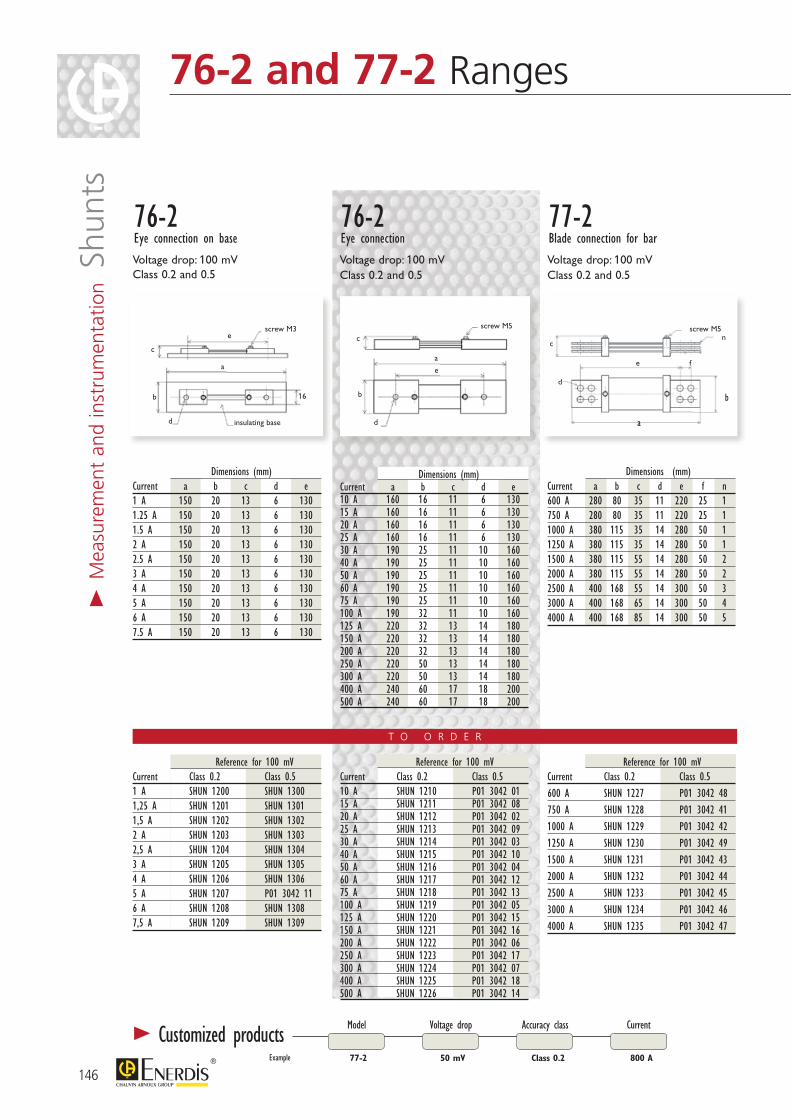
146
> M
easu
rem
ent
and
inst
rum
enta
tion S
hunt
s
a
e
16
screw M3
insulating based
b
ca
e
screw M5
d
b
c
a
e
n
f
screw M5
d
b
c
76-2Eye connection on base
76-2Eye connection
77-2Blade connection for bar
Reference for 100 mVCurrent Class 0.2 Class 0.51 A SHUN 1200 SHUN 13001,25 A SHUN 1201 SHUN 13011,5 A SHUN 1202 SHUN 13022 A SHUN 1203 SHUN 13032,5 A SHUN 1204 SHUN 13043 A SHUN 1205 SHUN 13054 A SHUN 1206 SHUN 13065 A SHUN 1207 P01 3042 116 A SHUN 1208 SHUN 13087,5 A SHUN 1209 SHUN 1309
Dimensions (mm)Current a b c d e1 A 150 20 13 6 1301.25 A 150 20 13 6 1301.5 A 150 20 13 6 1302 A 150 20 13 6 1302.5 A 150 20 13 6 1303 A 150 20 13 6 1304 A 150 20 13 6 1305 A 150 20 13 6 1306 A 150 20 13 6 1307.5 A 150 20 13 6 130
Dimensions (mm)Current a b c d e10 A 160 16 11 6 13015 A 160 16 11 6 13020 A 160 16 11 6 13025 A 160 16 11 6 13030 A 190 25 11 10 16040 A 190 25 11 10 16050 A 190 25 11 10 16060 A 190 25 11 10 16075 A 190 25 11 10 160100 A 190 32 11 10 160125 A 220 32 13 14 180150 A 220 32 13 14 180200 A 220 32 13 14 180250 A 220 50 13 14 180300 A 220 50 13 14 180400 A 240 60 17 18 200500 A 240 60 17 18 200
Reference for 100 mVCurrent Class 0.2 Class 0.510 A SHUN 1210 P01 3042 0115 A SHUN 1211 P01 3042 0820 A SHUN 1212 P01 3042 0225 A SHUN 1213 P01 3042 0930 A SHUN 1214 P01 3042 0340 A SHUN 1215 P01 3042 1050 A SHUN 1216 P01 3042 0460 A SHUN 1217 P01 3042 1275 A SHUN 1218 P01 3042 13100 A SHUN 1219 P01 3042 05125 A SHUN 1220 P01 3042 15150 A SHUN 1221 P01 3042 16200 A SHUN 1222 P01 3042 06250 A SHUN 1223 P01 3042 17300 A SHUN 1224 P01 3042 07400 A SHUN 1225 P01 3042 18500 A SHUN 1226 P01 3042 14
Reference for 100 mVCurrent Class 0.2 Class 0.5600 A SHUN 1227 P01 3042 48750 A SHUN 1228 P01 3042 411000 A SHUN 1229 P01 3042 421250 A SHUN 1230 P01 3042 491500 A SHUN 1231 P01 3042 432000 A SHUN 1232 P01 3042 442500 A SHUN 1233 P01 3042 453000 A SHUN 1234 P01 3042 464000 A SHUN 1235 P01 3042 47
Dimensions (mm) Current a b c d e f n600 A 280 80 35 11 220 25 1750 A 280 80 35 11 220 25 11000 A 380 115 35 14 280 50 11250 A 380 115 35 14 280 50 11500 A 380 115 55 14 280 50 22000 A 380 115 55 14 280 50 22500 A 400 168 55 14 300 50 33000 A 400 168 65 14 300 50 44000 A 400 168 85 14 300 50 5
Voltage drop: 100 mVClass 0.2 and 0.5
Voltage drop: 100 mVClass 0.2 and 0.5
Voltage drop: 100 mVClass 0.2 and 0.5
Model Voltage drop Accuracy class Current
77-2 50 mV 800 AClass 0.2
> Customized productsExample
76-2 and 77-2 Ranges
T O O R D E R

I nominal 2 h 5 s 5 s (In) class 0.2 class 0.5 and 1< 250 A 1.2 In 2 In 10 In250 to 2000 A 1.2 In 2 In 5 In> 2000 A 1.2 In 2 In 2 In
Kit of screw connectors + lead for shunt Reference1 to 25 A range 2919 990130 to 75 A range 2919 9902100 A range 2919 9903125 to 200 A range 2919 9904250 to 500 A range 2919 9905600 A and 750 A range 2919 9906
147
CURR
ENT
TRAN
SFOR
MER
SAN
D SH
UNTS
NETW
ORK
ANAL
YZER
SDA
TA L
OGGE
RS
AND
SOFT
WAR
E
ENER
GY M
ETER
S AN
D PO
WER
M
ONIT
ORS
Easy-to-connectbrass plates
> General specificationsAccuracy class defined in the following domain:Over the entire measurement rangeFor an ambient temperature of:-10°C to +35°C (class 0.2)-25°C to +40°C (class 0.5 and 1)For a blade temperature of 80°CFor a shunt current ≤ 5 mA
Permitted rated calibres:In = 1 A - 1.25 A - 1.5 A - 2 A - 2.5 A -3 A - 4 A - 5 A - 6 A - 7.5 A and their multiples or sub-multiples
Permitted overloads:On average and in normal operating conditions
Voltage drops:50 mV - 60 mV - 100 mV - 150 mV - 200 mV - 300 mV - 1 V
Compliance with standards:Accuracy and influence factor:IEC 60051-1 to 9Preferred ratings and dimensions for 100 mV shunts:NFC 42-151/152/153Lead-free range: RoHS directive(2002/95/CE)
> Mounting accessories
SHMI RangeOffering a vast range of industrial applications
Range with excellent PERFORMANCE/PRICE trade-off
A WIDE CHOICE of voltage drops
COMPACT DESIGN that respects accepted thermal dissipation requirements
PRODUCT ADVANTAGES
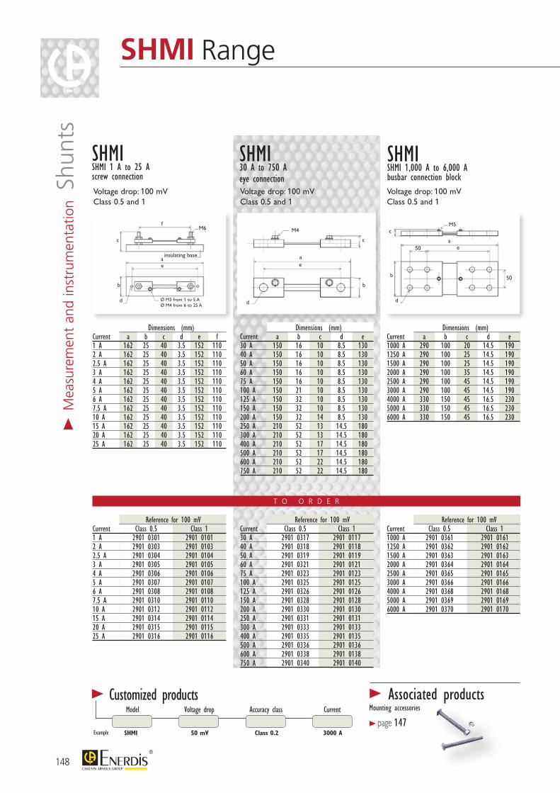
148
> M
easu
rem
ent
and
inst
rum
enta
tion S
hunt
s
Current Class 0.5 Class 130 A 2901 0317 2901 011740 A 2901 0318 2901 011850 A 2901 0319 2901 011960 A 2901 0321 2901 012175 A 2901 0323 2901 0123100 A 2901 0325 2901 0125125 A 2901 0326 2901 0126150 A 2901 0328 2901 0128200 A 2901 0330 2901 0130250 A 2901 0331 2901 0131300 A 2901 0333 2901 0133400 A 2901 0335 2901 0135500 A 2901 0336 2901 0136600 A 2901 0338 2901 0138750 A 2901 0340 2901 0140
SHMI Range
e
M6
insulating base
Ø M3 from 1 to 5 AØ M4 from 6 to 25 A
d
b
c
ae
M4
d
b
c
a
e
M5
50
50
d
b
c
a
SHMISHMI 1 A to 25 Ascrew connection
SHMI30 A to 750 A eye connection
SHMISHMI 1,000 A to 6,000 Abusbar connection block
Current Class 0.5 Class 11 A 2901 0301 2901 01012 A 2901 0303 2901 01032.5 A 2901 0304 2901 01043 A 2901 0305 2901 01054 A 2901 0306 2901 01065 A 2901 0307 2901 01076 A 2901 0308 2901 01087.5 A 2901 0310 2901 011010 A 2901 0312 2901 011215 A 2901 0314 2901 011420 A 2901 0315 2901 011525 A 2901 0316 2901 0116
Current Class 0.5 Class 11000 A 2901 0361 2901 01611250 A 2901 0362 2901 01621500 A 2901 0363 2901 01632000 A 2901 0364 2901 01642500 A 2901 0365 2901 01653000 A 2901 0366 2901 01664000 A 2901 0368 2901 01685000 A 2901 0369 2901 01696000 A 2901 0370 2901 0170
Voltage drop: 100 mVClass 0.5 and 1
Voltage drop: 100 mVClass 0.5 and 1
Voltage drop: 100 mVClass 0.5 and 1
Dimensions (mm) Current a b c d e30 A 150 16 10 8.5 13040 A 150 16 10 8.5 13050 A 150 16 10 8.5 13060 A 150 16 10 8.5 13075 A 150 16 10 8.5 130100 A 150 21 10 8.5 130125 A 150 32 10 8.5 130150 A 150 32 10 8.5 130200 A 150 32 14 8.5 130250 A 210 52 13 14.5 180300 A 210 52 13 14.5 180400 A 210 52 17 14.5 180500 A 210 52 17 14.5 180600 A 210 52 22 14.5 180750 A 210 52 22 14.5 180
Dimensions (mm) Current a b c d e f1 A 162 25 40 3.5 152 1102 A 162 25 40 3.5 152 1102.5 A 162 25 40 3.5 152 1103 A 162 25 40 3.5 152 1104 A 162 25 40 3.5 152 1105 A 162 25 40 3.5 152 1106 A 162 25 40 3.5 152 1107.5 A 162 25 40 3.5 152 11010 A 162 25 40 3.5 152 11015 A 162 25 40 3.5 152 11020 A 162 25 40 3.5 152 11025 A 162 25 40 3.5 152 110
Dimensions (mm) Current a b c d e1000 A 290 100 20 14.5 1901250 A 290 100 25 14.5 1901500 A 290 100 25 14.5 1902000 A 290 100 35 14.5 1902500 A 290 100 45 14.5 1903000 A 290 100 45 14.5 1904000 A 330 150 45 16.5 2305000 A 330 150 45 16.5 2306000 A 330 150 45 16.5 230
Model Voltage drop Accuracy class Current
SHMI 50 mV 3000 AClass 0.2Example
> Customized products > Associated productsMounting accessories
> page 147
f
T O O R D E R

> General specificationsAccuracy class 1 defined in the following domain:Over the entire measurement range For an ambient temperature of -25°C to +40°C For a blade temperature of 80°CFor a shunt current ≤ 5 mA
Permitted rated calibres:In = 1 A - 1.25 A - 1.5 A - 2 A - 2.5 A -3 A - 4 A - 5 A - 6 A - 7.5 A and their multiples or sub-multiplesMax. 300 A for SHEL and 60 A for SHMO
Permitted rated calibres:50 mV - 60 mV - 100 mV
Permitted overloads:On average and in normal operating conditions
Compliance with standards:Accuracy and influence factor:IEC 60051-1 to 9Lead-free range: RoHS directive(2002/95/CE)
I nominal (In) 2 h 5 s< 250 A 1.2 In 10 In≥ 250 A 1.2 In 5 In
149
CURR
ENT
TRAN
SFOR
MER
SAN
D SH
UNTS
NETW
ORK
ANAL
YZER
SDA
TA L
OGGE
RS
AND
SOFT
WAR
E
ENER
GY M
ETER
S AN
D PO
WER
M
ONIT
ORS
SHEL and SHMO RangesFor simplified installation on low-power networks
ECONOMY RANGE for construction (SHEL)
and for simplified installation (SHMO)
DIRECT CONNECTION to measuring component
(SHEL)
MODULAR CASING
for quick and easy mounting (SHMO)
COMPACT DESIGN (SHEL)
PRODUCT ADVANTAGES
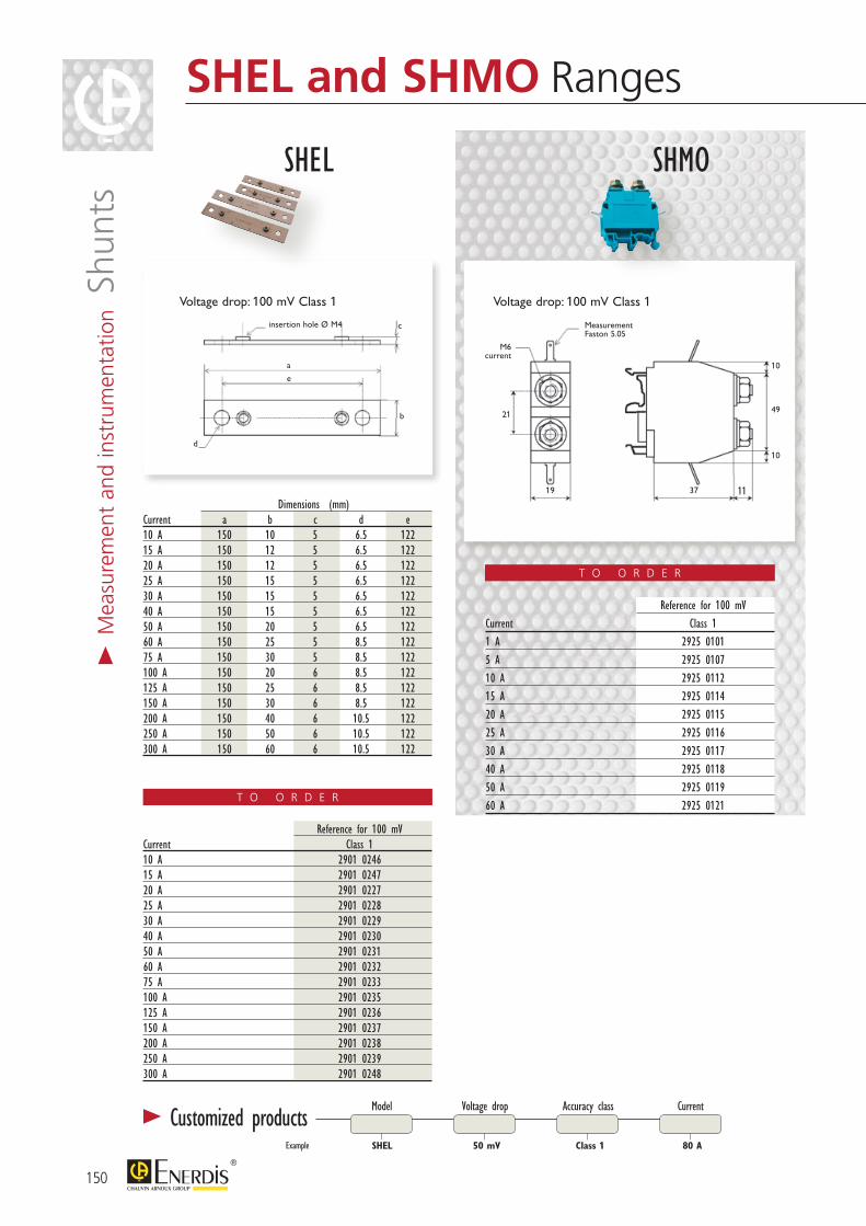
a
e
d
b
cinsertion hole Ø M4
10
21
19
M6current
MeasurementFaston 5.05
10
1137
49
Voltage drop: 100 mV Class 1
Dimensions (mm) Current a b c d e10 A 150 10 5 6.5 12215 A 150 12 5 6.5 12220 A 150 12 5 6.5 12225 A 150 15 5 6.5 12230 A 150 15 5 6.5 12240 A 150 15 5 6.5 12250 A 150 20 5 6.5 12260 A 150 25 5 8.5 12275 A 150 30 5 8.5 122100 A 150 20 6 8.5 122125 A 150 25 6 8.5 122150 A 150 30 6 8.5 122200 A 150 40 6 10.5 122250 A 150 50 6 10.5 122300 A 150 60 6 10.5 122
Reference for 100 mV Current Class 110 A 2901 024615 A 2901 024720 A 2901 022725 A 2901 022830 A 2901 022940 A 2901 023050 A 2901 023160 A 2901 023275 A 2901 0233100 A 2901 0235125 A 2901 0236150 A 2901 0237200 A 2901 0238250 A 2901 0239300 A 2901 0248
Voltage drop: 100 mV Class 1
Reference for 100 mV Current Class 11 A 2925 01015 A 2925 010710 A 2925 011215 A 2925 011420 A 2925 011525 A 2925 011630 A 2925 011740 A 2925 011850 A 2925 011960 A 2925 0121
Model Voltage drop Accuracy class Current
SHEL 50 mV 80 AClass 1
> Customized productsExample
SHEL SHMO
T O O R D E R
T O O R D E R
150
> M
easu
rem
ent
and
inst
rum
enta
tion S
hunt
sSHEL and SHMO Ranges
151
CURR
ENT
TRAN
SFOR
MER
SAN
D SH
UNTS
NETW
ORK
ANAL
YZER
SDA
TA L
OGGE
RS
AND
SOFT
WAR
E
ENER
GY M
ETER
S AN
D PO
WER
M
ONIT
ORS
Notes
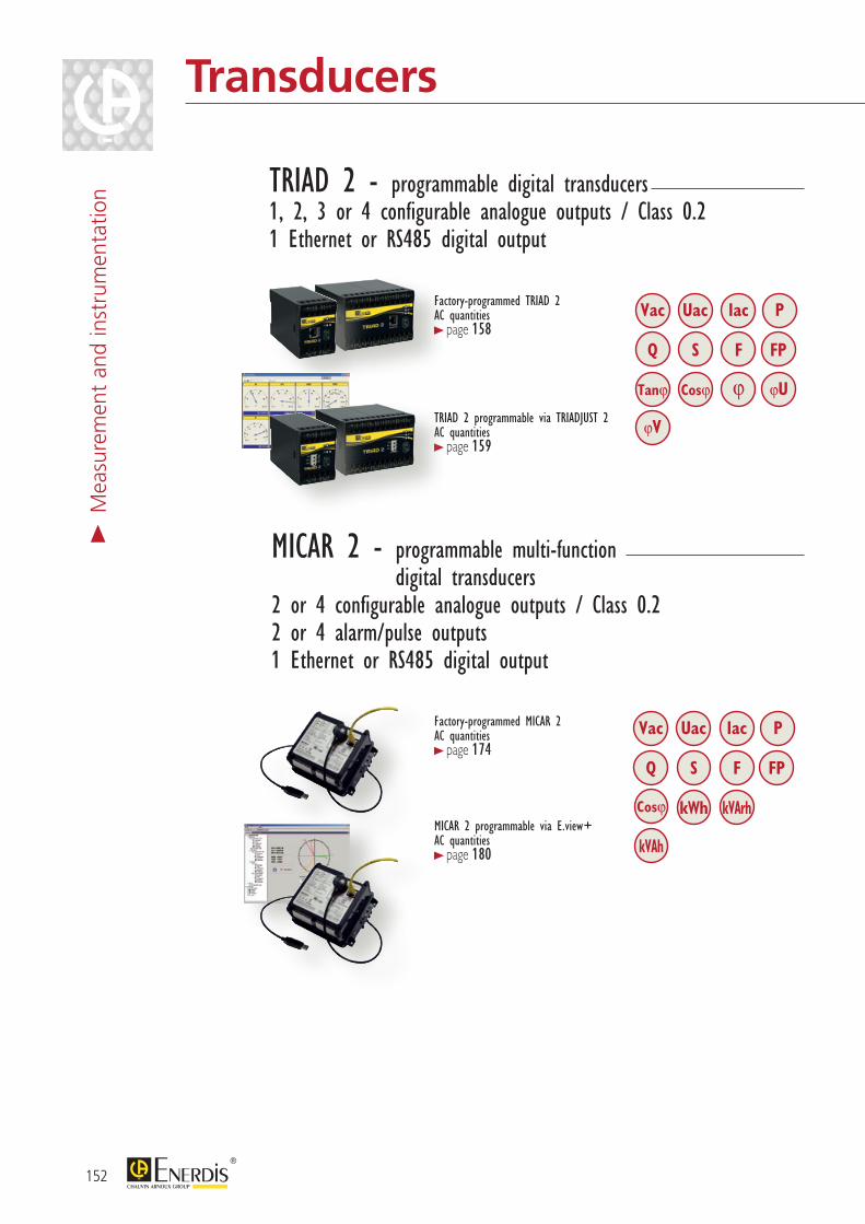
Vac
Q S
Cosϕ
Uac
Vac Iac P
Q S F FP
Tanϕ Cosϕ ϕU
ϕV
ϕ
Uac
kWh
Iac P
F FP
kVArh
kVAh
152
Transducers>
Mea
sure
men
t an
d in
stru
men
tatio
n TRIAD 2 - programmable digital transducers1, 2, 3 or 4 configurable analogue outputs / Class 0.21 Ethernet or RS485 digital output
MICAR 2 - programmable multi-function digital transducers
2 or 4 configurable analogue outputs / Class 0.22 or 4 alarm/pulse outputs1 Ethernet or RS485 digital output
Factory-programmed TRIAD 2AC quantities > page 158
TRIAD 2 programmable via TRIADJUST 2AC quantities > page 159
Factory-programmed MICAR 2AC quantities > page 174
MICAR 2 programmable via E.view+AC quantities > page 180
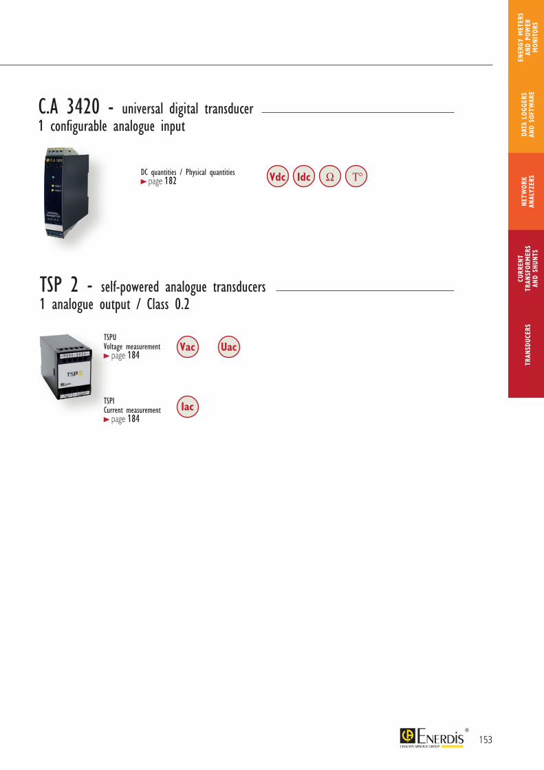
153
CURR
ENT
TRAN
SFOR
MER
SAN
D SH
UNTS
NETW
ORK
ANAL
YZER
STR
ANSD
UCER
SDA
TA L
OGGE
RS
AND
SOFT
WAR
E
ENER
GY M
ETER
S AN
D PO
WER
M
ONIT
ORS
TSPU Voltage measurement > page 184
Vac
TSP 2 - self-powered analogue transducers1 analogue output / Class 0.2
Uac
TSPI Current measurement > page 184
Iac
Vdc Idc Ω T°
C.A 3420 - universal digital transducer1 configurable analogue input
DC quantities / Physical quantities > page 182
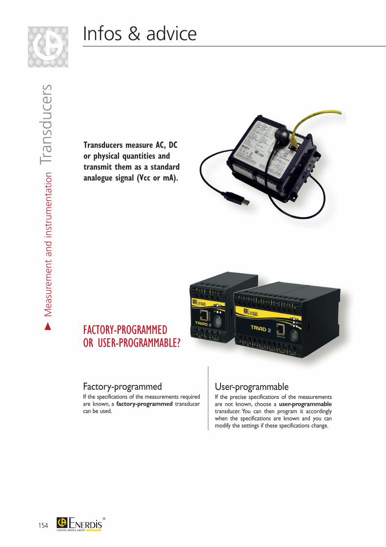
154
Infos & advice
FACTORY-PROGRAMMED OR USER-PROGRAMMABLE?
Factory-programmedIf the specifications of the measurements required are known, a factory-programmed transducer can be used.
User-programmableIf the precise specifications of the measurements are not known, choose a user-programmable transducer. You can then program it accordingly when the specifications are known and you can modify the settings if these specifications change.
Transducers measure AC, DC or physical quantities and transmit them as a standard analogue signal (Vcc or mA).
> M
easu
rem
ent
and
inst
rum
enta
tion T
rans
duce
rs
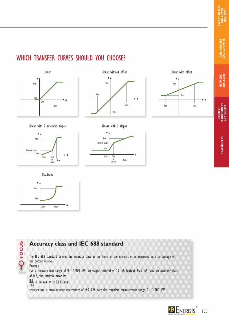
The IEC 688 standard defines the accuracy class as the limits of the intrinsic error expressed as a percentage of the output interval.Example:For a measurement range of 0 - 1,000 kW, an output interval of 16 mA (output 4-20 mA) and an accuracy class of 0.2, the intrinsic error is: 0.2 100
x 16 mA = ±0.032 mA
representing a measurement uncertainty of ±2 kW over the complete measurement range 0 - 1,000 kW.
Accuracy class and IEC 688 standard
FO
CU
S
155
CURR
ENT
TRAN
SFOR
MER
SAN
D SH
UNTS
NETW
ORK
ANAL
YZER
STR
ANSD
UCER
SDA
TA L
OGGE
RS
AND
SOFT
WAR
E
ENER
GY M
ETER
S AN
D PO
WER
M
ONIT
ORS
Linear Linear without offset Linear with offset
Linear with 2 extended slopes Linear with 2 slopes
Quadratic
WHICH TRANSFER CURVES SHOULD YOU CHOOSE?

Info & advice
Advantages of analogue outputs
> Universality: the nature of the output signal from the measurement transducer enables quick and easy connection to a wide range of instruments (recorders, controllers, calculators, analogue and digital panel meters, measurement relays, PLCs, RTUs, etc.).
> Response time: the response time of an analogue output enables real-time viewing of all electrical parameters (for example, SCADA application, dispatching, control and moni-toring of industrial processes).
> Resistance to disturbances: analogue signals (current outputs in particular) are not signifi-cantly affected by electromagnetic disturbances. A single shielded-pair wire enables you to transmit the output signal over very long distances (several hundred meters without signal amplification).
> Reliability: analogue transducer technology offers the advantage of several decades of application and use, benefiting from wide experi-ence in such varied fields as industry, building automation and electrical network supervision (dispatching).
Advantages of programmable transducers
The configuration software associated with transducers enables you to adapt transducer specifications to application needs at all times and stages of the application.
> Reduction of stocks and maintenance costsA programmable transducer can replace any other product as necessary, helping to reduce stocks for maintenance.
> Quickly and easily replaceable productsProgrammability makes it easy to replace products quickly, thus cutting maintenance time.
> Adaptable to installation evolutionsThe programmable transducer can be modified at all times, especially in the case of modification of initial specifications or information unavailable at the outset.
Advantages of digital outputs
> Remote access for easy maintenance: with digital outputs, it is possible to create a communicating network so that you can set the products’ parameters remotely.
> Remote meter-reading: using the commands available in the ModBus mapping, a transducer can be operated via a digital supervision system and remote-read all the electrical quantities available per product on the same bus.
> Extra functions: the digital outputs on our transducers can be used to access functions which were previously unavailable, such as alarm, date-stamping or energy index functions.
> M
easu
rem
ent
and
inst
rum
enta
tion T
rans
duce
rs a
nd r
ecor
ders
156
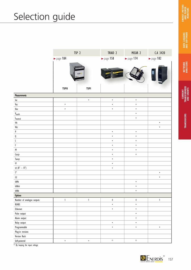
Selection guide
TSPU TSPI
Measurements
lac • • •
Vac • • •
Uac • • •
Vearth •
Ineutral •
Idc •
Vdc •
P • •
Q • •
S • •
F • •
PF • •
Cosϕ • •
Tanϕ •ϕ •
ϕ (U’ – U’’) •
T° •
Ω •
kWh •
kVArh •
kVAh •
Options
Number of analogue outputs 1 1 4 4 1
RS485 • •
Ethernet • •
Pulse output •
Alarm output •
Relay output • •
Programmable • • •
Plug-in versions
Version Rack
Self-powered • • (1) (1)
(1) By looping the input voltage
> page 184
MICAR 2 C.A 3420TSP 2 TRIAD 2
> page 174 > page 182> page 158
157
CURR
ENT
TRAN
SFOR
MER
SAN
D SH
UNTS
NETW
ORK
ANAL
YZER
STR
ANSD
UCER
SDA
TA L
OGGE
RS
AND
SOFT
WAR
E
ENER
GY M
ETER
S AN
D PO
WER
M
ONIT
ORS
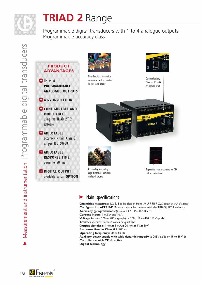
> Main specificationsQuantities measured: 1, 2, 3, 4 to be chosen from I, V, U, F, FP, P, Q, S, cosϕ, ϕ, ϕU, ϕV, tanϕConfiguration of TRIAD 2: in factory or by the user with the TRIADJUST 2 softwareAccuracy (programmable): Class 0.1 / 0.15 / 0.2 /0.5 / 1Current inputs: 1 A, 5 A and 10 AVoltage inputs: 100 to 480 V (ph-ph) or 100 / √3 to 480 / √3 V (ph-N)Transfer curves: linear, 2 slopes or quadraticOutput signals: ± 1 mA, ± 5 mA, ± 20 mA, ± 1 V, ± 10 VResponse time in Class 0.2: 200 msOperating frequency: 50 or 60 HzAuxiliary power supply with wide dynamic range: 80 to 265 V ac/dc or 19 to 58 V dcCompliance with CE directiveDigital technology
Multi-function, economical instrument with 4 functions in the same casing
Communication, Ethernet RS 485 or optical head
Accessibility and safety: large-dimension terminalsInsulated circuits
Ergonomic: easy mounting on DIN rail or switchboard
158
> M
easu
rem
ent
and
inst
rum
enta
tion P
rogr
amm
able
dig
ital t
rans
duce
rsTRIAD 2 RangeProgrammable digital transducers with 1 to 4 analogue outputsProgrammable accuracy class
PRODUCT ADVANTAGES
Up to 4 PROGRAMMABLE ANALOGUE OUTPUTS
4 kV INSULATION
CONFIGURABLE AND MODIFIABLE
using the TRIADJUST 2 software
ADJUSTABLE accuracy within Class 0.1 as per IEC 60688
ADJUSTABLE RESPONSE TIME
down to 50 ms
DIGITAL OUTPUT available as an OPTION
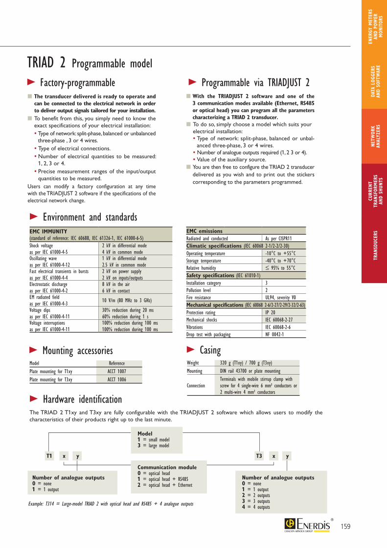
> Environment and standardsEMC IMMUNITY (standard of reference: IEC 60688, IEC 61326-1, IEC 61000-6-5)Shock voltage as per IEC 61000-4-5
2 kV in differential mode4 kV in common mode
Oscillating wave as per IEC 61000-4-12
1 kV in differential mode2.5 kV in common mode
Fast electrical transients in bursts as per IEC 61000-4-4
2 kV on power supply2 kV on inputs/outputs
Electrostatic discharge as per IEC 61000-4-2
8 kV in the air6 kV in contact
EM radiated field as per IEC 61000-4-3 10 V/m (80 MHz to 3 GHz)
Voltage dips as per IEC 61000-4-11
30% reduction during 20 ms60% reduction during 1 s
Voltage interruptions as per IEC 61000-4-11
100% reduction during 100 ms100% reduction during 100 ms
EMC emissionsRadiated and conducted As per CISPR11Climatic specifications (IEC 60068 2-1/2-2/2-30)Operating temperature -10°C to +55°CStorage temperature -40°C to +70°CRelative humidity ≤ 95% to 55°CSafety specifications (IEC 61010-1)Installation category 3Pollution level 2Fire resistance UL94, severity V0Mechanical specifications (IEC 60068 2-6/2-27/2-29/2-32/2-63)Protection rating IP 20Mechanical shocks IEC 60068-2-27Vibrations IEC 60068-2-6Drop test with packaging NF 0042-1
> Mounting accessoriesModel ReferencePlate mounting for T1xy ACCT 1007Plate mounting for T3xy ACCT 1006
> CasingWeight 320 g (T1xy) / 700 g (T3xy)Mounting DIN rail 43700 or plate mounting Terminals with mobile stirrup clamp with Connection screw for 4 single-wire 6 mm² conductors or 2 multi-wire 4 mm² conductors
TRIAD 2 Programmable model
The transducer delivered is ready to operate and can be connected to the electrical network in order to deliver output signals tailored for your installation.
To benefit from this, you simply need to know the exact specifications of your electrical installation:• Type of network: split-phase, balanced or unbalanced
three-phase , 3 or 4 wires.• Type of electrical connections. • Number of electrical quantities to be measured:
1, 2, 3 or 4.• Precise measurement ranges of the input/output
quantities to be measured.Users can modify a factory configuration at any time with the TRIADJUST 2 software if the specifications of the electrical network change.
> Factory-programmable > Programmable via TRIADJUST 2 With the TRIADJUST 2 software and one of the
3 communication modes available (Ethernet, RS485 or optical head) you can program all the parameters characterizing a TRIAD 2 transducer.
To do so, simply choose a model which suits your electrical installation:• Type of network: split-phase, balanced or unbal-
anced three-phase, 3 or 4 wires. • Number of analogue outputs required (1, 2 3 or 4).• Value of the auxiliary source.
You are then free to configure the TRIAD 2 transducer delivered as you wish and to print out the stickers corresponding to the parameters programmed.
159
CURR
ENT
TRAN
SFOR
MER
SAN
D SH
UNTS
NETW
ORK
ANAL
YZER
STR
ANSD
UCER
SDA
TA L
OGGE
RS
AND
SOFT
WAR
E
ENER
GY M
ETER
S AN
D PO
WER
M
ONIT
ORS
Model1 = small model3 = large model
Communication module0 = optical head1 = optical head + RS4852 = optical head + Ethernet
T3 x y
Number of analogue outputs0 = none1 = 1 output2 = 2 outputs3 = 3 outputs4 = 4 outputs
T1 x y
Number of analogue outputs0 = none1 = 1 output
Example: T314 = Large-model TRIAD 2 with optical head and RS485 + 4 analogue outputs
The TRIAD 2 T1xy and T3xy are fully configurable with the TRIADJUST 2 software which allows users to modify the characteristics of their products right up to the last minute.
> Hardware identification
Network Function T1xy model T3xy model
Single-phase
V • •I • •F • •P • •Q • •S • •FP • •
Tanϕ • •Cosϕ • •ϕ • •
Balanced 3-phase, 3 wires
U12, U23, U31 • •I1, I2, I3 • •
F • •Pt • •Qt • •St • •FPt • •
Tanϕ • •Cosϕt • •ϕt • •
I1, I2, I3 signed • •
Balanced 3-phase, 4 wires
V1, V2, V3 • •U12, U23, U31 • •
I1, I2, I3 • •F • •
P1, P2, P3, Pt • •Q1, Q2, Q3, Qt • •S1, S2, S3, St • •
FP1, FP2, FP3, FPt • •Tanϕ • •
Cos (ϕ1, ϕ2, ϕ3, ϕt) • •ϕ1, ϕ2, ϕ3, ϕt • •I1, I2, I3 signed • •
Unbalanced 3-phase, 3/4 wires
V1, V2, V3 •U12, U23, U31 •
I1, I2, I3 •F •
P1, P2, P3, Pt •Q1, Q2, Q3, Qt •S1, S2, S3, St •
FP1, FP2, FP3, FPt •Tanϕ •
Cos (ϕ1, ϕ2, ϕ3, ϕt) •ϕ1, ϕ2, ϕ3, ϕt •
ϕ (U12/U23, U23/U31, U31/U12) •ϕ (V1/V2, V2/V3, V3/V1) •
I1, I2, I3 signed •
Split-phase
V1, V2 •U12 •I1, I2 •
F •P1, P2, Pt •Q1, Q2, Qt •S1, S2, St •
FP1, FP2, FPt •Tanϕ •
Cos (ϕ1, ϕ2, ϕt) •ϕ1, ϕ2, ϕt •ϕ (V1/V2) •
I1 signed, I2 signed •
160
TRIAD 2 Range>
Mea
sure
men
t an
d in
stru
men
tatio
n Pro
gram
mab
le d
igita
l tra
nsdu
cers
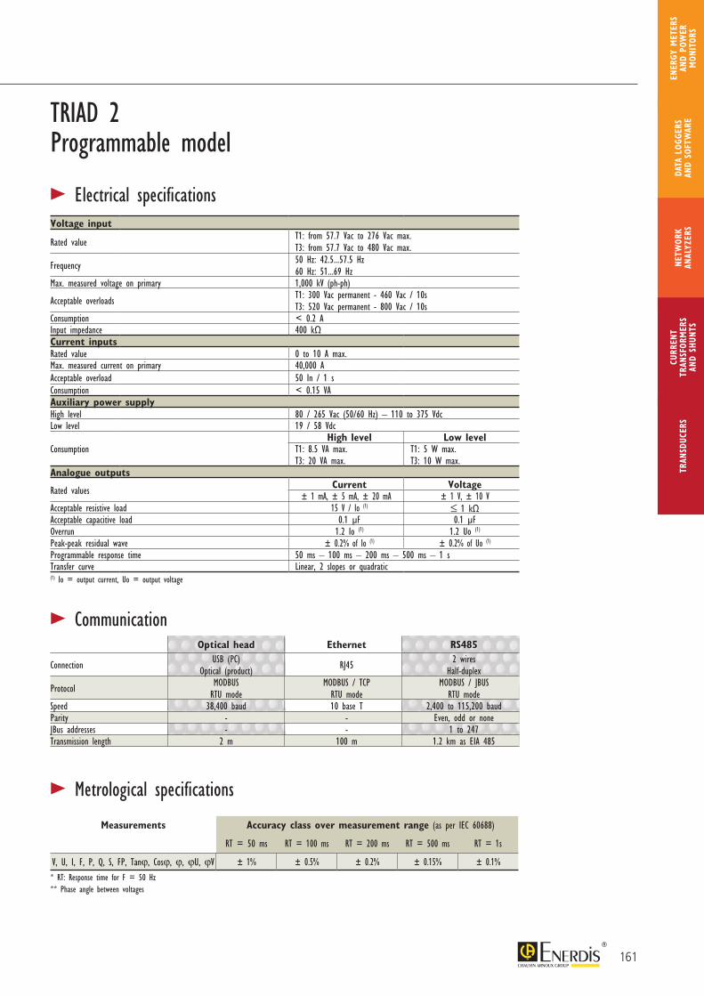
Voltage input
Rated valueT1: from 57.7 Vac to 276 Vac max.T3: from 57.7 Vac to 480 Vac max.
Frequency 50 Hz: 42.5...57.5 Hz 60 Hz: 51...69 Hz
Max. measured voltage on primary 1,000 kV (ph-ph)
Acceptable overloads T1: 300 Vac permanent - 460 Vac / 10sT3: 520 Vac permanent - 800 Vac / 10s
Consumption < 0.2 AInput impedance 400 kΩCurrent inputsRated value 0 to 10 A max.Max. measured current on primary 40,000 AAcceptable overload 50 In / 1 sConsumption < 0.15 VAAuxiliary power supplyHigh level 80 / 265 Vac (50/60 Hz) – 110 to 375 VdcLow level 19 / 58 Vdc
ConsumptionHigh level Low level
T1: 8.5 VA max.T3: 20 VA max.
T1: 5 W max.T3: 10 W max.
Analogue outputs
Rated values Current Voltage± 1 mA, ± 5 mA, ± 20 mA ± 1 V, ± 10 V
Acceptable resistive load 15 V / Io (1) ≤ 1 kΩAcceptable capacitive load 0.1 μF 0.1 μFOverrun 1.2 Io (1) 1.2 Uo (1)
Peak-peak residual wave ± 0.2% of Io (1) ± 0.2% of Uo (1)
Programmable response time 50 ms – 100 ms – 200 ms – 500 ms – 1 sTransfer curve Linear, 2 slopes or quadratic(1) Io = output current, Uo = output voltage
TRIAD 2 Programmable model
161
CURR
ENT
TRAN
SFOR
MER
SAN
D SH
UNTS
NETW
ORK
ANAL
YZER
STR
ANSD
UCER
SDA
TA L
OGGE
RS
AND
SOFT
WAR
E
ENER
GY M
ETER
S AN
D PO
WER
M
ONIT
ORS
> Electrical specifications
Optical head Ethernet RS485
Connection USB (PC)Optical (product) RJ45 2 wires
Half-duplex
Protocol MODBUSRTU mode
MODBUS / TCPRTU mode
MODBUS / JBUSRTU mode
Speed 38,400 baud 10 base T 2,400 to 115,200 baudParity - - Even, odd or noneJBus addresses - - 1 to 247Transmission length 2 m 100 m 1.2 km as EIA 485
> Communication
Measurements Accuracy class over measurement range (as per IEC 60688)
RT = 50 ms RT = 100 ms RT = 200 ms RT = 500 ms RT = 1s
V, U, I, F, P, Q, S, FP, Tanϕ, Cosϕ, ϕ, ϕU, ϕV ± 1% ± 0.5% ± 0.2% ± 0.15% ± 0.1%
> Metrological specifications
* RT: Response time for F = 50 Hz** Phase angle between voltages
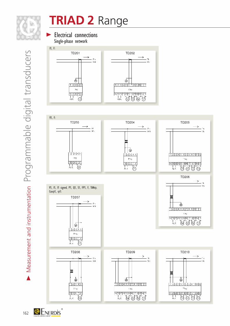
I1, F:
V1, F:
V1, I1, I1 signed, P1, Q1, S1, FP1, F, TANϕ, Cosϕ1, ϕ1:
162
TRIAD 2 Range> Electrical connections
Single-phase network
> M
easu
rem
ent
and
inst
rum
enta
tion P
rogr
amm
able
dig
ital t
rans
duce
rs
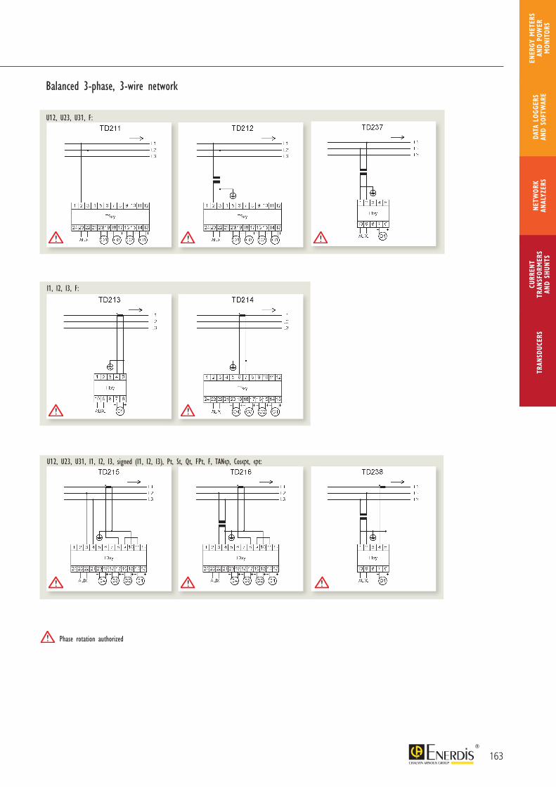
Balanced 3-phase, 3-wire network
U12, U23, U31, F:
I1, I2, I3, F:
U12, U23, U31, I1, I2, I3, signed (I1, I2, I3), Pt, St, Qt, FPt, F, TANϕ, Cosϕt, ϕt:
Phase rotation authorized
163
CURR
ENT
TRAN
SFOR
MER
SAN
D SH
UNTS
NETW
ORK
ANAL
YZER
STR
ANSD
UCER
SDA
TA L
OGGE
RS
AND
SOFT
WAR
E
ENER
GY M
ETER
S AN
D PO
WER
M
ONIT
ORS
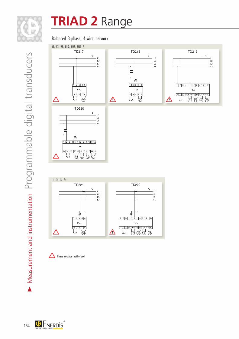
Phase rotation authorized
164
TRIAD 2 RangeBalanced 3-phase, 4-wire networkV1, V2, V3, U12, U23, U31 F:
I1, I2, I3, F:
> M
easu
rem
ent
and
inst
rum
enta
tion P
rogr
amm
able
dig
ital t
rans
duce
rs
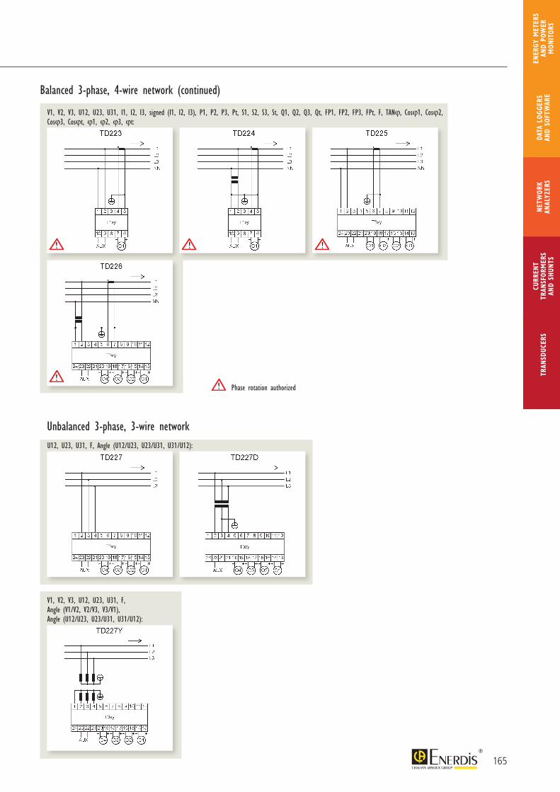
Phase rotation authorized
165
CURR
ENT
TRAN
SFOR
MER
SAN
D SH
UNTS
NETW
ORK
ANAL
YZER
STR
ANSD
UCER
SDA
TA L
OGGE
RS
AND
SOFT
WAR
E
ENER
GY M
ETER
S AN
D PO
WER
M
ONIT
ORS
V1, V2, V3, U12, U23, U31, F, Angle (V1/V2, V2/V3, V3/V1), Angle (U12/U23, U23/U31, U31/U12):
Balanced 3-phase, 4-wire network (continued)
V1, V2, V3, U12, U23, U31, I1, I2, I3, signed (I1, I2, I3), P1, P2, P3, Pt, S1, S2, S3, St, Q1, Q2, Q3, Qt, FP1, FP2, FP3, FPt, F, TANϕ, Cosϕ1, Cosϕ2, Cosϕ3, Cosϕt, ϕ1, ϕ2, ϕ3, ϕt:
Unbalanced 3-phase, 3-wire networkU12, U23, U31, F, Angle (U12/U23, U23/U31, U31/U12):
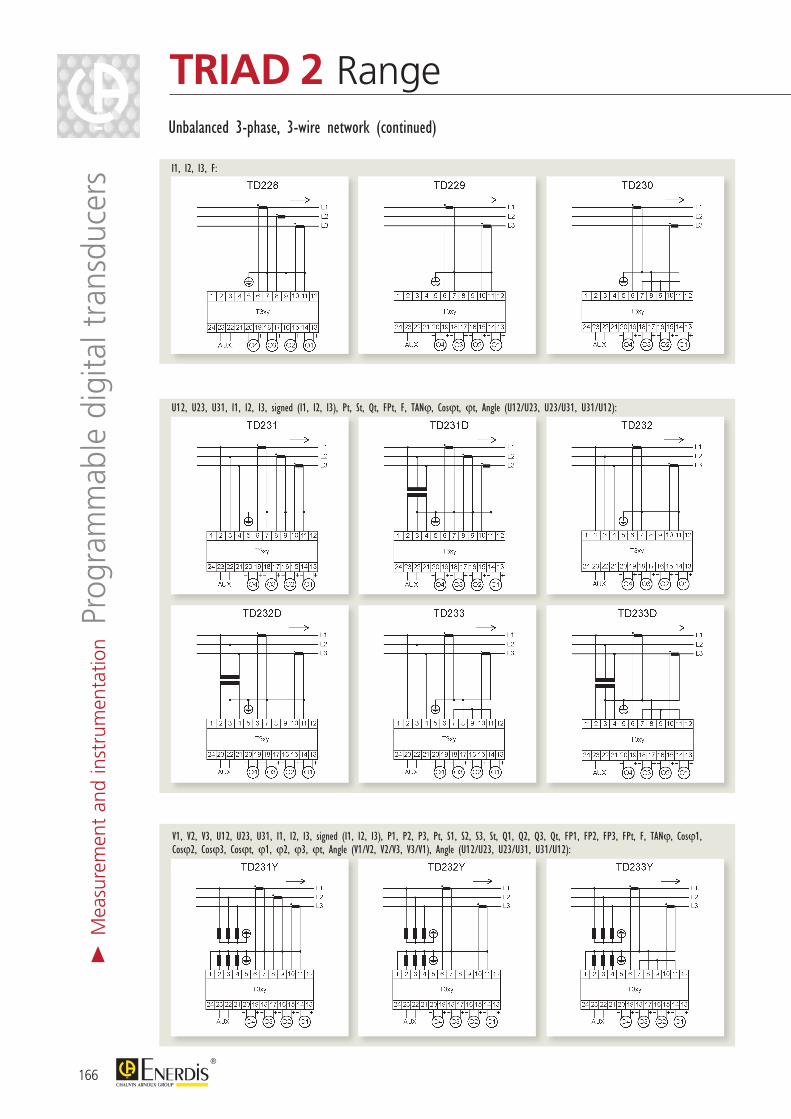
166
TRIAD 2 Range>
Mea
sure
men
t an
d in
stru
men
tatio
n Pro
gram
mab
le d
igita
l tra
nsdu
cers
V1, V2, V3, U12, U23, U31, I1, I2, I3, signed (I1, I2, I3), P1, P2, P3, Pt, S1, S2, S3, St, Q1, Q2, Q3, Qt, FP1, FP2, FP3, FPt, F, TANϕ, Cosϕ1, Cosϕ2, Cosϕ3, Cosϕt, ϕ1, ϕ2, ϕ3, ϕt, Angle (V1/V2, V2/V3, V3/V1), Angle (U12/U23, U23/U31, U31/U12):
I1, I2, I3, F:
Unbalanced 3-phase, 3-wire network (continued)
U12, U23, U31, I1, I2, I3, signed (I1, I2, I3), Pt, St, Qt, FPt, F, TANϕ, Cosϕt, ϕt, Angle (U12/U23, U23/U31, U31/U12):
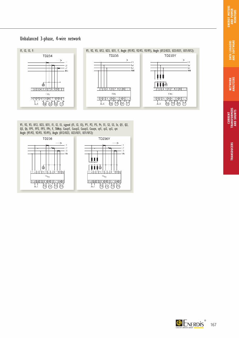
Unbalanced 3-phase, 4-wire network
I1, I2, I3, F: V1, V2, V3, U12, U23, U31, F, Angle (V1/V2, V2/V3, V3/V1), Angle (U12/U23, U23/U31, U31/U12):
V1, V2, V3, U12, U23, U31, I1, I2, I3, signed (I1, I2, I3), P1, P2, P3, Pt, S1, S2, S3, St, Q1, Q2, Q3, Qt, FP1, FP2, FP3, FPt, F, TANϕ, Cosϕ1, Cosϕ2, Cosϕ3, Cosϕt, ϕ1, ϕ2, ϕ3, ϕt Angle (V1/V2, V2/V3, V3/V1), Angle (U12/U23, U23/U31, U31/U12):
167
CURR
ENT
TRAN
SFOR
MER
SAN
D SH
UNTS
NETW
ORK
ANAL
YZER
STR
ANSD
UCER
SDA
TA L
OGGE
RS
AND
SOFT
WAR
E
ENER
GY M
ETER
S AN
D PO
WER
M
ONIT
ORS
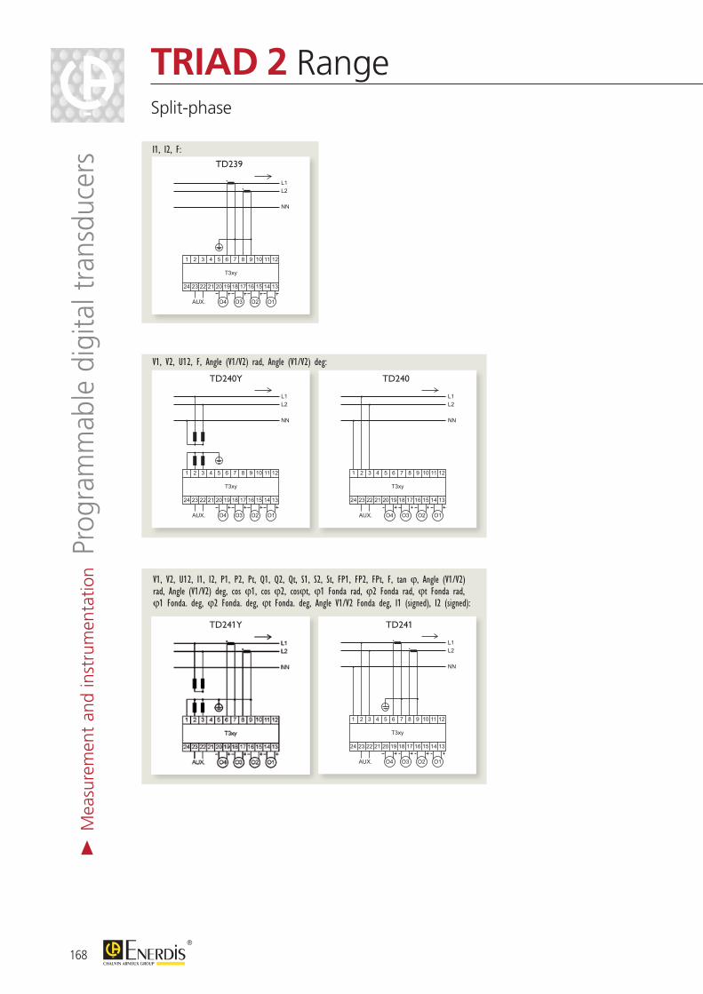
168
TRIAD 2 RangeSplit-phase
> M
easu
rem
ent
and
inst
rum
enta
tion P
rogr
amm
able
dig
ital t
rans
duce
rs
V1, V2, U12, I1, I2, P1, P2, Pt, Q1, Q2, Qt, S1, S2, St, FP1, FP2, FPt, F, tan ϕ, Angle (V1/V2) rad, Angle (V1/V2) deg, cos ϕ1, cos ϕ2, cosϕt, ϕ1 Fonda rad, ϕ2 Fonda rad, ϕt Fonda rad, ϕ1 Fonda. deg, ϕ2 Fonda. deg, ϕt Fonda. deg, Angle V1/V2 Fonda deg, I1 (signed), I2 (signed):
L2L1
T3xy
2 3 4 5 6 7 8 9 10 11 121
23 22 21 20 19 18 17 16 15 14 1324
AUX. O1O2O3O4
NN
TD239I1, I2, F:
L2L1
NN
T3xy
2 3 4 5 6 7 8 9 10 11 121
23 22 21 20 19 18 17 16 15 14 1324
AUX. O1O2O3O4
TD240Y
L2L1
NN
T3xy
2 3 4 5 6 7 8 9 10 11 121
23 22 21 20 19 18 17 16 15 14 1324
AUX. O1O2O3O4
TD240
V1, V2, U12, F, Angle (V1/V2) rad, Angle (V1/V2) deg:
L2L1
NN
T3xy
2 3 4 5 6 7 8 9 10 11 121
23 22 21 20 19 18 17 16 15 14 1324
AUX. O1O2O3O4
TD241
TD239
TD240Y TD240
TD241TD241Y
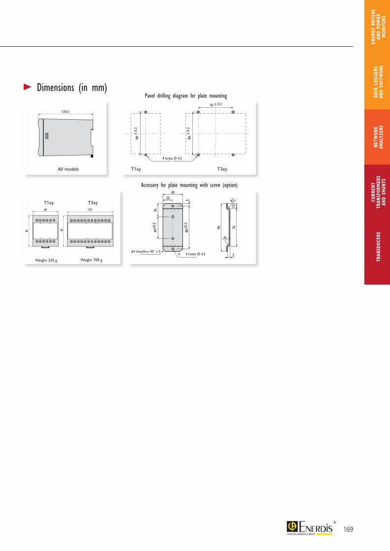
169
CURR
ENT
TRAN
SFOR
MER
SAN
D SH
UNTS
NETW
ORK
ANAL
YZER
STR
ANSD
UCER
SDA
TA L
OGGE
RS
AND
SOFT
WAR
E
ENER
GY M
ETER
S AN
D PO
WER
M
ONIT
ORS
20
4 chamfers 45 ° x 5 4 holes Ø4.5
R1
R2
40
86±0
.25
7610
2644
±0.2
96
5
86
±0
.2
86
±0
.2
T11, TSPI et TSPU
Panel drilling diagram for plate mounting
Accessory for plate mounting with screw (option)
T12, T13, T21, T22, T23, T31, T32 et T33T11, TSPU et TSPI
T12, T13, T21, T22, T23, T31, T32 et T33
4 holes ø 4.5
70±0.2
60 120
120.5
8181
> Dimensions (in mm)Panel drilling diagram for plate mounting
Accessory for plate mounting with screw (option)
All models
20
4 chamfers 45 ° x 5 4 holes Ø4.5
R1
R2
40
86±0
.25
7610
2644
±0.2
96
5
86
±0
.2
86
±0
.2
T11, TSPI et TSPU
Panel drilling diagram for plate mounting
Accessory for plate mounting with screw (option)
T12, T13, T21, T22, T23, T31, T32 et T33T11, TSPU et TSPI
T12, T13, T21, T22, T23, T31, T32 et T33
4 holes ø 4.5
70±0.2
60 120
120.5
8181
T1xy
4 holes Ø 4,5
86 ±
0,2
86 ±
0,2
70 ± 0,2
T3xy
20
4 chamfers 45 ° x 5 4 holes Ø4.5
R1
R2
40
86±0
.25
7610
2644
±0.2
96
5
86
±0
.2
86
±0
.2
T11, TSPI et TSPU
Panel drilling diagram for plate mounting
Accessory for plate mounting with screw (option)
T12, T13, T21, T22, T23, T31, T32 et T33T11, TSPU et TSPI
T12, T13, T21, T22, T23, T31, T32 et T33
4 holes ø 4.5
70±0.2
60 120
120.5
8181
Weight: 320 g Weight: 700 g
T1xy T3xy
120,5
20
4 chamfers 45 ° x 5 4 holes Ø4.5
R1
R2
40
86±0
.25
7610
2644
±0.2
96
5
86
±0
.2
86
±0
.2
T11, TSPI et TSPU
Panel drilling diagram for plate mounting
Accessory for plate mounting with screw (option)
T12, T13, T21, T22, T23, T31, T32 et T33T11, TSPU et TSPI
T12, T13, T21, T22, T23, T31, T32 et T33
4 holes ø 4.5
70±0.2
60 120
120.5
8181
4 chamfers 45° x 54 holes Ø 4,5
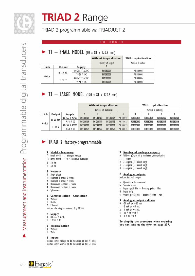
T O O R D E R
Without tropicalization With tropicalization
Number of output1
Number of output1Link Output Supply
Optical± 20 mA
80-265 V AC/DC P01380001 P0138000219-58 V DC P01380003 P01380004
± 10 V80-265 V AC/DC P01380005 P01380006
19-58 V DC P01380007 P01380008
> T1 – SMALL MODEL (60 x 81 x 120.5 mm)
> T3 – LARGE MODEL (120 x 81 x 120.5 mm)
Without tropicalization With tropicalization
Number of output(s) Number of output(s)
Link Output Supply 1 2 3 4 1 2 3 4
Optical± 20 mA
80-265 V AC/DC P01380101 P01380103 P01380105 P01380107 P01380102 P01380104 P01380106 P0138010819-58 V DC P01380109 P01380111 P01380113 P01380115 P01380110 P01380112 P01380114 P01380116
± 10 V80-265 V AC/DC P01380117 P01380119 P01380121 P01380123 P01380118 P01380120 P01380122 P01380124
19-58 V DC P01380125 P01380127 P01380129 P01380131 P01380126 P01380128 P01380130 P01380132
> TRIAD 2 factory-programmable
1 Model - Frequency T1: small model – 1 analogue output T3: large model – 1 to 4 analogue output(s) 0: 50 Hz 1: 60 Hz
2 Network 0: Single-phase 1: Balanced 3-phase, 3 wires 2: Balanced 3-phase, 4 wires 3: Unbalanced 3-phase, 3 wires 4: Unbalanced 3-phase, 4 wires 5: Split-phase
3 Communication - Connection 0: Without 1: RS485 2: Ethernet Indicate the diagram number. E.g. TD204
4 Supply 0: 80-265 V AC/DC 1: 19-58 V DC
5 Tropicalization 0: Without 1: With
6 Inputs Indicate direct voltage to be measured or the VT ratio Indicate direct current to be measured or the CT ratio
7 Number of analogue outputs 0: Without (Choice of a minimum communication) 1: 1 output 2: 2 outputs (T3 model only) 3: 3 outputs (T3 model only) 4: 4 outputs (T3 model only)
8 Analogue outputs Indicate for each output:
a- Quantity to be measured b- Transfer curve c- Input signal: Min – Breaking point - Max d- Input unity e- Output signal: Min – Breaking point - Max
9 Analogue output calibres 0: -20 mA to +20 mA 1: -5 mA to +5 mA 2: -1 mA to +1 mA 3: -10 V to +10 V 4: -1 V to +1 V
To simplify the procedure when ordering you can send us the form on page 237.
170
TRIAD 2 RangeTRIAD 2 programmable via TRIADJUST 2
> M
easu
rem
ent
and
inst
rum
enta
tion P
rogr
amm
able
dig
ital t
rans
duce
rs
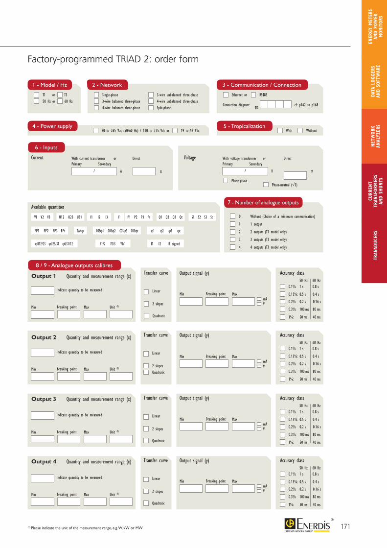
171
CURR
ENT
TRAN
SFOR
MER
SAN
D SH
UNTS
NETW
ORK
ANAL
YZER
STR
ANSD
UCER
SDA
TA L
OGGE
RS
AND
SOFT
WAR
E
ENER
GY M
ETER
S AN
D PO
WER
M
ONIT
ORS
Factory-programmed TRIAD 2: order form
(1) Please indicate the unit of the measurement range, e.g. W, kW or MW
Current With current transformer or Direct
6 - Inputs
A A
/
Primary SecondaryVoltage With voltage transformer or Direct
V V
/
Primary Secondary
Phase-phasePhase-neutral (√3)
4 - Power supply 5 - Tropicalization80 to 265 Vac (50/60 Hz) / 110 to 375 Vdc or With Without19 to 58 Vdc
2 - Network
Single-phase
3-wire balanced three-phase
4-wire balanced three-phase
3-wire unbalanced three-phase
4-wire unbalanced three-phase
Split-phase
3 - Communication / Connection
Ethernet or
Connection diagram: cf: p162 to p168
RS485
TD
V1 V2 V3 U12 U23 U31 I1 I2 I3
I1 I2 I3 signed
F P1 P2 P3 Pt Q1 Q2 Q3 Qt S1 S2 S3 St
FP1 FP2 FP3 FPt TANϕ COSϕ1 COSϕ2 COSϕ3 COSϕt ϕ1 ϕ2 ϕ3 ϕt
ϕU12/23 ϕU23/31 ϕU31/12 V1/2 V2/3 V3/1
Available quantities
1 - Model / Hz
T1 or
50 Hz or
Quantity and measurement range (x)
Min
Transfer curve
Linear
2 slopes
Quadratic
breaking point Max Unit (1)
Indicate quantity to be measured
Output signal (y)
mAMin Breaking point Max
V
Quantity and measurement range (x)
Quantity and measurement range (x)
Quantity and measurement range (x)
Min
Transfer curve
Linear
2 slopesQuadratic
breaking point Max Unit (1)
Indicate quantity to be measured
Output signal (y)
Min
Transfer curve
Linear
2 slopes
Quadratic
breaking point Max Unit (1)
Indicate quantity to be measured
Output signal (y)
Min
Transfer curve
Linear
2 slopes
Quadratic
breaking point Max Unit (1)
Indicate quantity to be measured
Output signal (y)
T3
60 Hz
mAMin Breaking point Max
V
mAMin Breaking point Max
V
mAMin Breaking point Max
V
Accuracy class
0.1%: 1 s 0.8 s
0.15%: 0.5 s 0.4 s
0.2%: 0.2 s 0.16 s
0.3%: 100 ms 80 ms
1%: 50 ms 40 ms
50 Hz 60 Hz
Accuracy class
0.1%: 1 s 0.8 s
0.15%: 0.5 s 0.4 s
0.2%: 0.2 s 0.16 s
0.3%: 100 ms 80 ms
1%: 50 ms 40 ms
50 Hz 60 Hz
Accuracy class
0.1%: 1 s 0.8 s
0.15%: 0.5 s 0.4 s
0.2%: 0.2 s 0.16 s
0.3%: 100 ms 80 ms
1%: 50 ms 40 ms
50 Hz 60 Hz
Accuracy class
0.1%: 1 s 0.8 s
0.15%: 0.5 s 0.4 s
0.2%: 0.2 s 0.16 s
0.3%: 100 ms 80 ms
1%: 50 ms 40 ms
50 Hz 60 Hz
7 - Number of analogue outputs
0: Without (Choice of a minimum communication)
1: 1 output
2: 2 outputs (T3 model only)
3: 3 outputs (T3 model only)
4: 4 outputs (T3 model only)
Output 1
Output 2
Output 3
Output 4
8 / 9 - Analogue outputs calibres
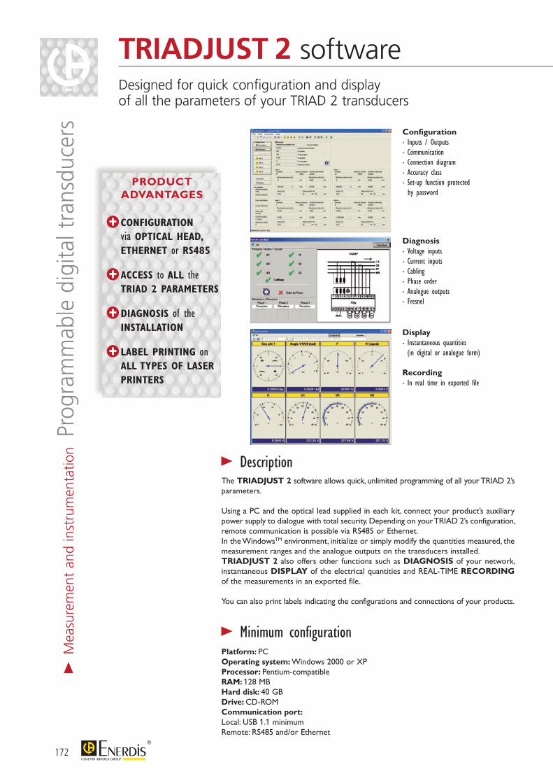
Diagnosis- Voltage inputs- Current inputs- Cabling- Phase order- Analogue outputs- Fresnel
Configuration- Inputs / Outputs- Communication- Connection diagram- Accuracy class- Set-up function protected by password
Display- Instantaneous quantities (in digital or analogue form)
Recording - In real time in exported file
> DescriptionThe TRIADJUST 2 software allows quick, unlimited programming of all your TRIAD 2’s parameters.
Using a PC and the optical lead supplied in each kit, connect your product’s auxiliary power supply to dialogue with total security. Depending on your TRIAD 2’s configuration, remote communication is possible via RS485 or Ethernet.In the WindowsTM environment, initialize or simply modify the quantities measured, the measurement ranges and the analogue outputs on the transducers installed.TRIADJUST 2 also offers other functions such as DIAGNOSIS of your network, instantaneous DISPLAY of the electrical quantities and REAL-TIME RECORDING of the measurements in an exported file.
You can also print labels indicating the configurations and connections of your products.
Platform: PCOperating system: Windows 2000 or XPProcessor: Pentium-compatibleRAM: 128 MBHard disk: 40 GBDrive: CD-ROMCommunication port:Local: USB 1.1 minimumRemote: RS485 and/or Ethernet
> Minimum configuration
172
TRIADJUST 2 softwareDesigned for quick configuration and display of all the parameters of your TRIAD 2 transducers
> M
easu
rem
ent
and
inst
rum
enta
tion P
rogr
amm
able
dig
ital t
rans
duce
rs
PRODUCT ADVANTAGES
CONFIGURATION via OPTICAL HEAD, ETHERNET or RS485
ACCESS to ALL the TRIAD 2 PARAMETERS
DIAGNOSIS of the INSTALLATION
LABEL PRINTING on ALL TYPES OF LASER PRINTERS
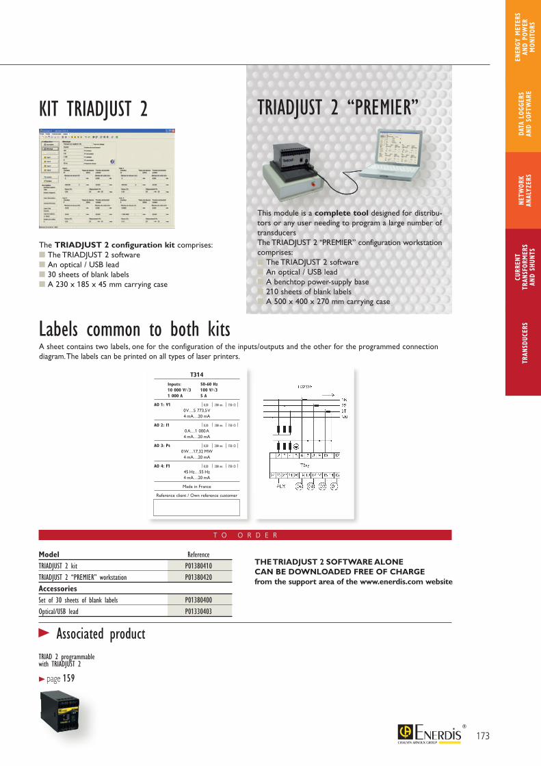
T O O R D E R
Model ReferenceTRIADJUST 2 kit P01380410TRIADJUST 2 “PREMIER” workstation P01380420Accessories Set of 30 sheets of blank labels P01380400Optical/USB lead P01330403
This module is a complete tool designed for distribu-tors or any user needing to program a large number of transducersThe TRIADJUST 2 “PREMIER” configuration workstation comprises: The TRIADJUST 2 software An optical / USB lead A benchtop power-supply base 210 sheets of blank labels A 500 x 400 x 270 mm carrying case
The TRIADJUST 2 configuration kit comprises: The TRIADJUST 2 software An optical / USB lead 30 sheets of blank labels A 230 x 185 x 45 mm carrying case
TRIADJUST 2 “PREMIER”KIT TRIADJUST 2
A sheet contains two labels, one for the configuration of the inputs/outputs and the other for the programmed connection diagram. The labels can be printed on all types of laser printers.
Labels common to both kits
173
CURR
ENT
TRAN
SFOR
MER
SAN
D SH
UNTS
NETW
ORK
ANAL
YZER
STR
ANSD
UCER
SDA
TA L
OGGE
RS
AND
SOFT
WAR
E
ENER
GY M
ETER
S AN
D PO
WER
M
ONIT
ORS
> Associated productTRIAD 2 programmable with TRIADJUST 2
> page 159
T314 Inputs: 50-60 Hz 10 000 V/√3 100 V/√3 1 000 A 5 A
AO 1: V1 0,20 200 ms 750 Ω
0 V…5 773,5 V4 mA…20 mA
AO 2: I1 0,20 200 ms 750 Ω
0 A…1 000 A4 mA…20 mA
AO 3: Pt 0,20 200 ms 750 Ω
0 W…17,32 MW4 mA…20 mA
AO 4: F1 0,20 200 ms 750 Ω
45 Hz…55 Hz4 mA…20 mA
Made in France
Reference client / Own reference customer
THE TRIADJUST 2 SOFTWARE ALONE CAN BE DOWNLOADED FREE OF CHARGE from the support area of the www.enerdis.com website

174
MICAR 2 RangeMulti-function digital transducers 2 or 4 analogue outputs / Class 0.2
> M
easu
rem
ent
and
inst
rum
enta
tion M
ulti-
func
tion
digi
tal t
rans
duce
rs
Simplified connection with screw-on terminal strip
Local communication via optical head
Remote communication via Ethernet network
Quantities measured:Choice of 1, 2, 3 or 4 among 32 electrical quantitiesConfiguration: in factory or by user with the E.view+ softwareAccuracy: Class 0.2Current inputs: 1 A and 5 AVoltage inputs: 100 to 400 V (ph-ph) or 100 / √3 to 400 / √3 V (ph-N)Transfer curves: linear, 2 slopes, quadraticOutput signal: configurable between - 20 mA and + 20 mAResponse time: 350 msOperating frequency: 50 or 60 HzAuxiliary source with wide dynamic range: 80 to 264 V ac/dc or 19 to 57 VdcCompliance with CE directive
> General specifications
PRODUCT ADVANTAGES
CLASS 0.2 Insulation 4 kV
Up to 4 CONFIGURABLE ANALOGUE OUTPUTS
Option of 2 or 4 ON-OFF outputs
COMMUNICATION and programming via optical head or remotely via Ethernet network or RS485 output
ELECTRICAL NETWORK SUPERVISION and display of the energy values, harmonics and THD using the E.view+ software
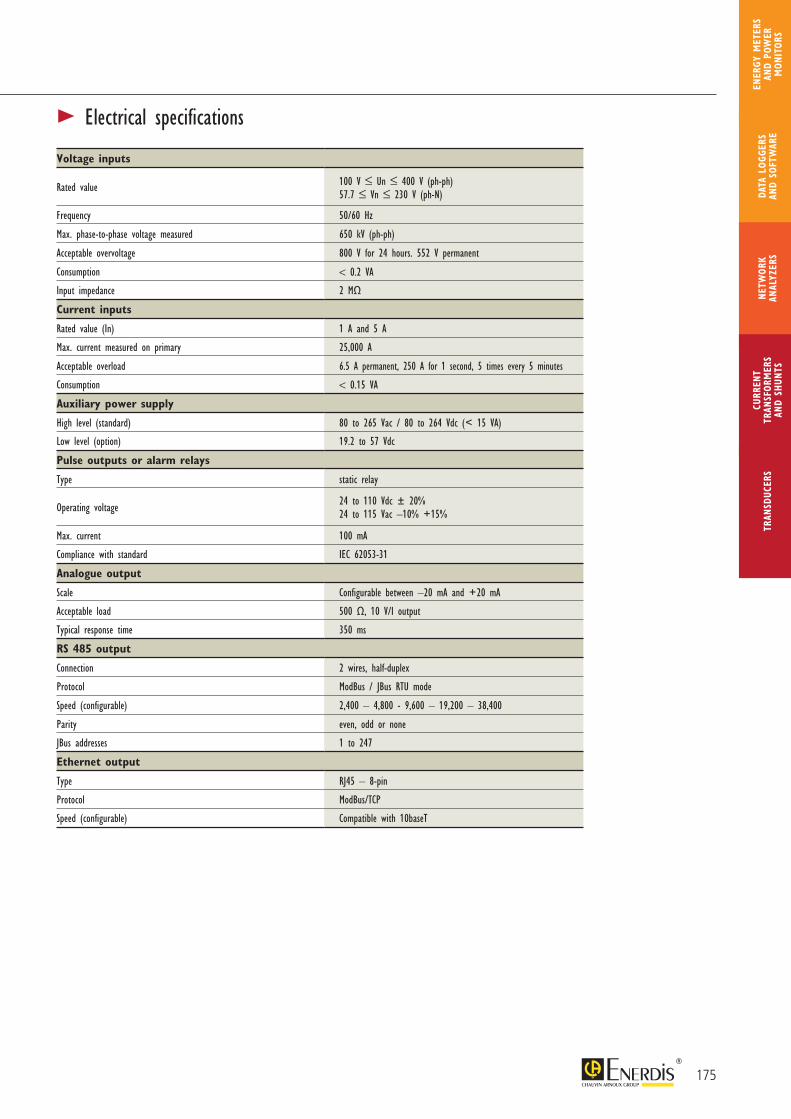
Voltage inputs
Rated value 100 V ≤ Un ≤ 400 V (ph-ph)57.7 ≤ Vn ≤ 230 V (ph-N)
Frequency 50/60 Hz
Max. phase-to-phase voltage measured 650 kV (ph-ph)
Acceptable overvoltage 800 V for 24 hours. 552 V permanent
Consumption < 0.2 VA
Input impedance 2 MΩ
Current inputs
Rated value (In) 1 A and 5 A
Max. current measured on primary 25,000 A
Acceptable overload 6.5 A permanent, 250 A for 1 second, 5 times every 5 minutes
Consumption < 0.15 VA
Auxiliary power supply
High level (standard) 80 to 265 Vac / 80 to 264 Vdc (< 15 VA)
Low level (option) 19.2 to 57 Vdc
Pulse outputs or alarm relays
Type static relay
Operating voltage 24 to 110 Vdc ± 20%24 to 115 Vac –10% +15%
Max. current 100 mA
Compliance with standard IEC 62053-31
Analogue output
Scale Configurable between –20 mA and +20 mA
Acceptable load 500 Ω, 10 V/I output
Typical response time 350 ms
RS 485 output
Connection 2 wires, half-duplex
Protocol ModBus / JBus RTU mode
Speed (configurable) 2,400 – 4,800 - 9,600 – 19,200 – 38,400
Parity even, odd or none
JBus addresses 1 to 247
Ethernet output
Type RJ45 – 8-pin
Protocol ModBus/TCP
Speed (configurable) Compatible with 10baseT
175
CURR
ENT
TRAN
SFOR
MER
SAN
D SH
UNTS
NETW
ORK
ANAL
YZER
STR
ANSD
UCER
SDA
TA L
OGGE
RS
AND
SOFT
WAR
E
ENER
GY M
ETER
S AN
D PO
WER
M
ONIT
ORS
> Electrical specifications
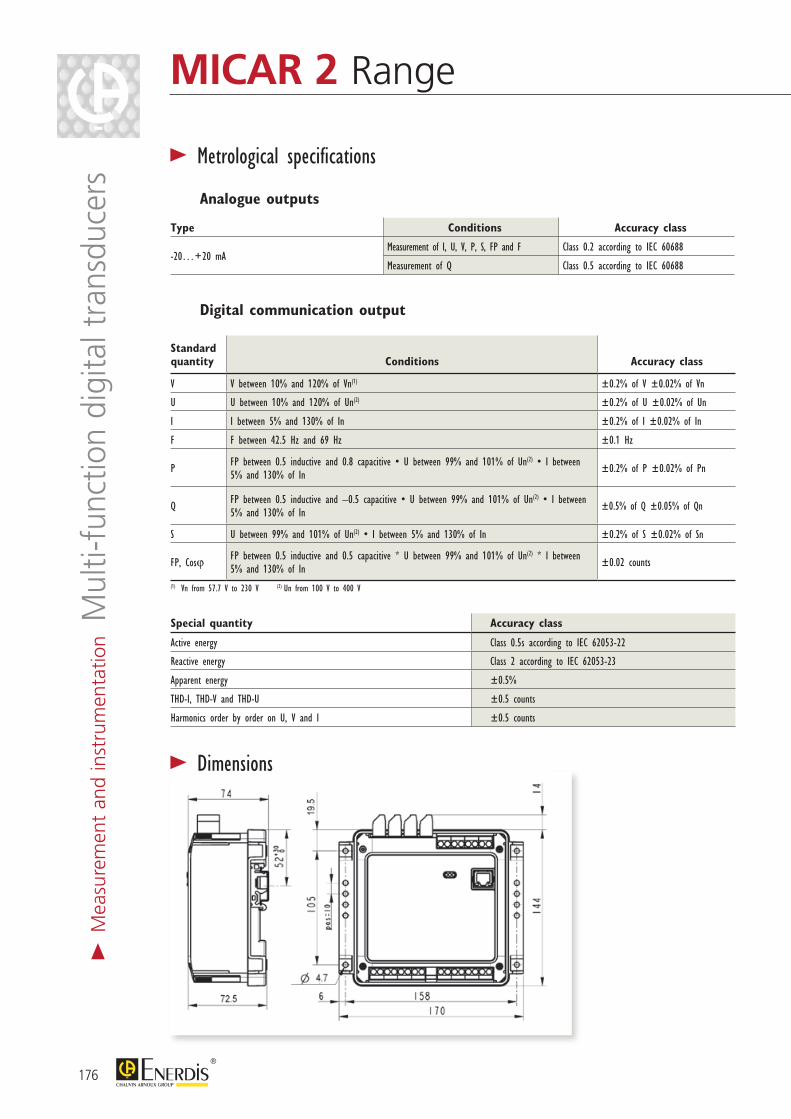
176
MICAR 2 Range
Type Conditions Accuracy class
-20…+20 mAMeasurement of I, U, V, P, S, FP and F Class 0.2 according to IEC 60688
Measurement of Q Class 0.5 according to IEC 60688
> Metrological specificationsAnalogue outputs
Standard quantity Conditions Accuracy class
V V between 10% and 120% of Vn(1) ±0.2% of V ±0.02% of Vn
U U between 10% and 120% of Un(2) ±0.2% of U ±0.02% of Un
I I between 5% and 130% of In ±0.2% of I ±0.02% of In
F F between 42.5 Hz and 69 Hz ±0.1 Hz
P FP between 0.5 inductive and 0.8 capacitive • U between 99% and 101% of Un(2) • I between 5% and 130% of In ±0.2% of P ±0.02% of Pn
Q FP between 0.5 inductive and –0.5 capacitive • U between 99% and 101% of Un(2) • I between 5% and 130% of In ±0.5% of Q ±0.05% of Qn
S U between 99% and 101% of Un(2) • I between 5% and 130% of In ±0.2% of S ±0.02% of Sn
FP, Cosϕ FP between 0.5 inductive and 0.5 capacitive * U between 99% and 101% of Un(2) * I between 5% and 130% of In ±0.02 counts
(1) Vn from 57.7 V to 230 V (2) Un from 100 V to 400 V
Digital communication output
Special quantity Accuracy class
Active energy Class 0.5s according to IEC 62053-22
Reactive energy Class 2 according to IEC 62053-23
Apparent energy ±0.5%
THD-I, THD-V and THD-U ±0.5 counts
Harmonics order by order on U, V and I ±0.5 counts
> Dimensions
> M
easu
rem
ent
and
inst
rum
enta
tion M
ulti-
func
tion
digi
tal t
rans
duce
rs
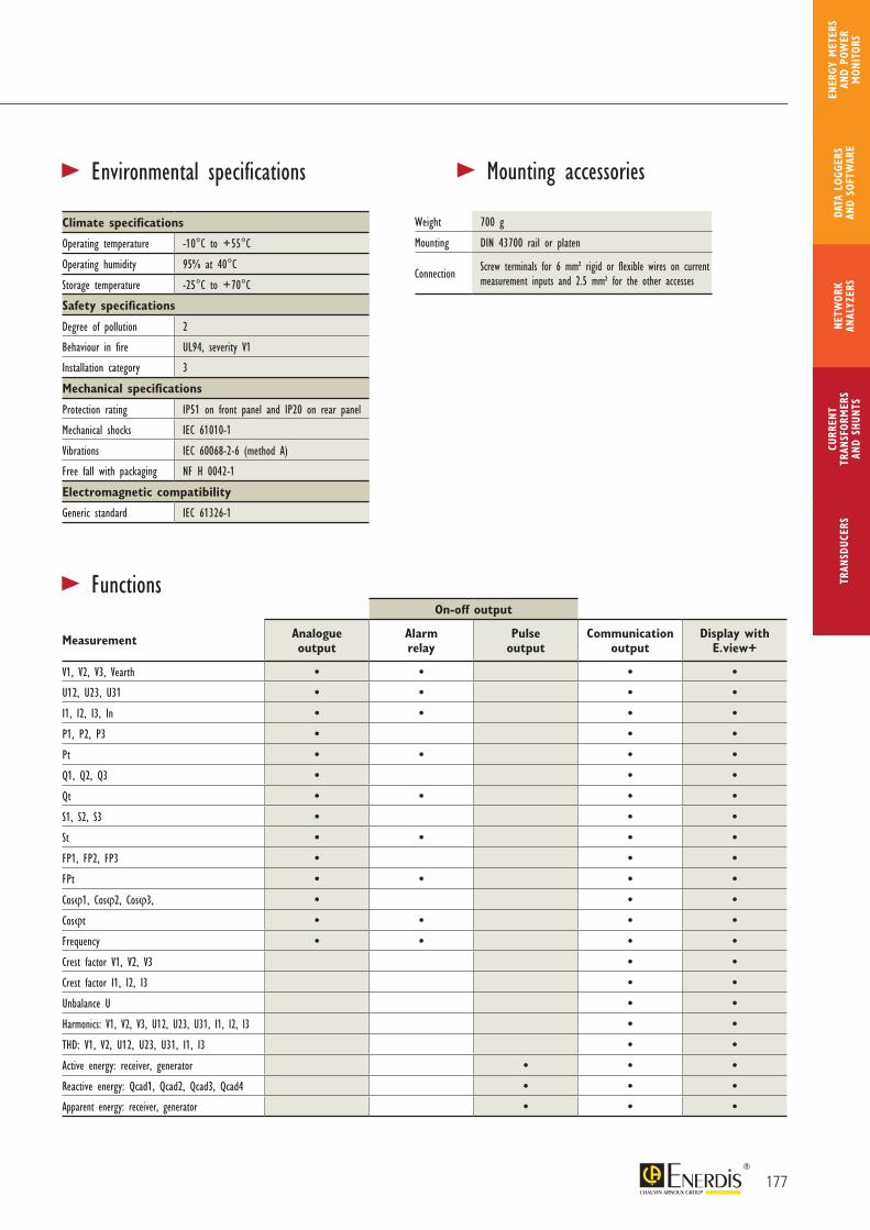
177
CURR
ENT
TRAN
SFOR
MER
SAN
D SH
UNTS
NETW
ORK
ANAL
YZER
STR
ANSD
UCER
SDA
TA L
OGGE
RS
AND
SOFT
WAR
E
ENER
GY M
ETER
S AN
D PO
WER
M
ONIT
ORS
> Mounting accessories> Environmental specifications
Climate specifications
Operating temperature -10°C to +55°C
Operating humidity 95% at 40°C
Storage temperature -25°C to +70°C
Safety specifications
Degree of pollution 2
Behaviour in fire UL94, severity V1
Installation category 3
Mechanical specifications
Protection rating IP51 on front panel and IP20 on rear panel
Mechanical shocks IEC 61010-1
Vibrations IEC 60068-2-6 (method A)
Free fall with packaging NF H 0042-1
Electromagnetic compatibility
Generic standard IEC 61326-1
Weight 700 g
Mounting DIN 43700 rail or platen
Connection Screw terminals for 6 mm² rigid or flexible wires on current measurement inputs and 2.5 mm² for the other accesses
On-off output
Measurement Analogue output
Alarm relay
Pulse output
Communication output
Display with E.view+
V1, V2, V3, Vearth • • • •U12, U23, U31 • • • •I1, I2, I3, In • • • •P1, P2, P3 • • •Pt • • • •Q1, Q2, Q3 • • •Qt • • • •S1, S2, S3 • • •St • • • •FP1, FP2, FP3 • • •FPt • • • •Cosϕ1, Cosϕ2, Cosϕ3, • • •Cosϕt • • • •Frequency • • • •Crest factor V1, V2, V3 • •Crest factor I1, I2, I3 • •Unbalance U • •Harmonics: V1, V2, V3, U12, U23, U31, I1, I2, I3 • •THD: V1, V2, U12, U23, U31, I1, I3 • •Active energy: receiver, generator • • •Reactive energy: Qcad1, Qcad2, Qcad3, Qcad4 • • •Apparent energy: receiver, generator • • •
> Functions
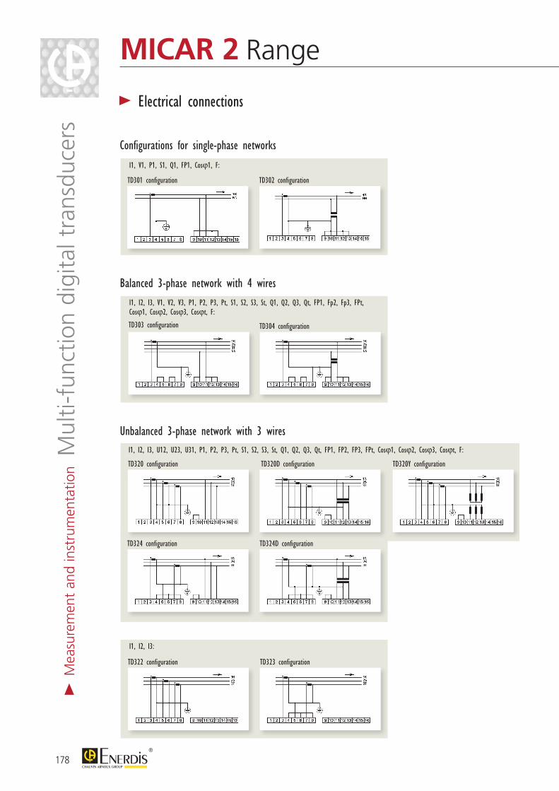
Configurations for single-phase networks
I1, V1, P1, S1, Q1, FP1, Cosϕ1, F:
Balanced 3-phase network with 4 wiresI1, I2, I3, V1, V2, V3, P1, P2, P3, Pt, S1, S2, S3, St, Q1, Q2, Q3, Qt, FP1, Fp2, Fp3, FPt, Cosϕ1, Cosϕ2, Cosϕ3, Cosϕt, F:
Unbalanced 3-phase network with 3 wiresI1, I2, I3, U12, U23, U31, P1, P2, P3, Pt, S1, S2, S3, St, Q1, Q2, Q3, Qt, FP1, FP2, FP3, FPt, Cosϕ1, Cosϕ2, Cosϕ3, Cosϕt, F:
I1, I2, I3:
178
MICAR 2 Range>
Mea
sure
men
t an
d in
stru
men
tatio
n Mul
ti-fu
nctio
n di
gita
l tra
nsdu
cers
> Electrical connections
TD303 configuration TD304 configuration
TD301 configuration TD302 configuration
TD320 configuration TD320D configuration TD320Y configuration
TD324 configuration TD324D configuration
TD322 configuration TD323 configuration
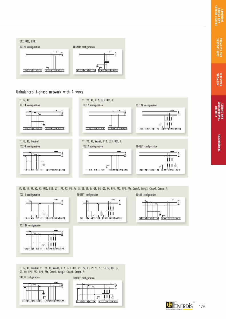
U12, U23, U31:
I1, I2, I3: V1, V2, V3, U12, U23, U31, F:
Unbalanced 3-phase network with 4 wires
I1, I2, I3, Ineutral: V1, V2, V3, Vearth, U12, U23, U31, F:
I1, I2, I3, V1, V2, V3, U12, U23, U31, P1, P2, P3, Pt, S1, S2, S3, St, Q1, Q2, Q3, Qt, FP1, FP2, FP3, FPt, Cosϕ1, Cosϕ2, Cosϕ3, Cosϕt, F:
I1, I2, I3, Ineutral, V1, V2, V3, Vearth, U12, U23, U31, P1, P2, P3, Pt, S1, S2, S3, St, Q1, Q2, Q3, Qt, FP1, FP2, FP3, FPt, Cosϕ1, Cosϕ2, Cosϕ3, Cosϕt, F:
179
CURR
ENT
TRAN
SFOR
MER
SAN
D SH
UNTS
NETW
ORK
ANAL
YZER
STR
ANSD
UCER
SDA
TA L
OGGE
RS
AND
SOFT
WAR
E
ENER
GY M
ETER
S AN
D PO
WER
M
ONIT
ORS
TD314 configuration TD317 configuration TD317Y configuration
TD318 configuration
TD334 configuration TD337 configuration TD337Y configuration
TD338 configuration TD338Y configuration
TD321 configuration TD321D configuration
TD315 configuration TD315Y configuration
TD318Y configuration
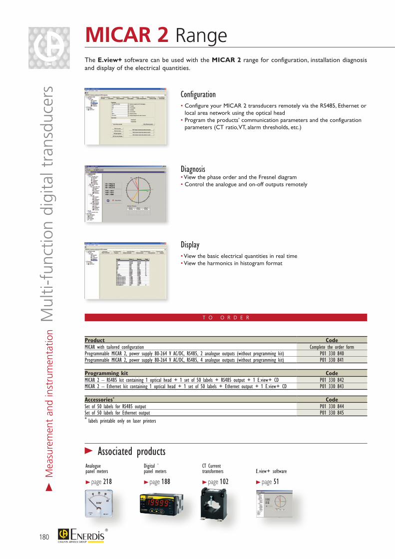
T O O R D E R
The E.view+ software can be used with the MICAR 2 range for configuration, installation diagnosis and display of the electrical quantities.
Configuration• Configure your MICAR 2 transducers remotely via the RS485, Ethernet or
local area network using the optical head• Program the products’ communication parameters and the configuration
parameters (CT ratio, VT, alarm thresholds, etc.)
Diagnosis• View the phase order and the Fresnel diagram• Control the analogue and on-off outputs remotely
Display• View the basic electrical quantities in real time• View the harmonics in histogram format
180
MICAR 2 Range>
Mea
sure
men
t an
d in
stru
men
tatio
n Mul
ti-fu
nctio
n di
gita
l tra
nsdu
cers
Product CodeMICAR with tailored configuration Complete the order formProgrammable MICAR 2, power supply 80-264 V AC/DC, RS485, 2 analogue outputs (without programming kit) P01 330 840Programmable MICAR 2, power supply 80-264 V AC/DC, RS485, 4 analogue outputs (without programming kit) P01 330 841
Programming kit CodeMICAR 2 – RS485 kit containing 1 optical head + 1 set of 50 labels + RS485 output + 1 E.view+ CD P01 330 842MICAR 2 – Ethernet kit containing 1 optical head + 1 set of 50 labels + Ethernet output + 1 E.view+ CD P01 330 843
Accessories* CodeSet of 50 labels for RS485 output P01 330 844Set of 50 labels for Ethernet output P01 330 845* labels printable only on laser printers
> Associated productsAnalogue panel meters
> page 218
Digital `panel meters
> page 188
CT Current transformers
> page 102E.view+ software
> page 51
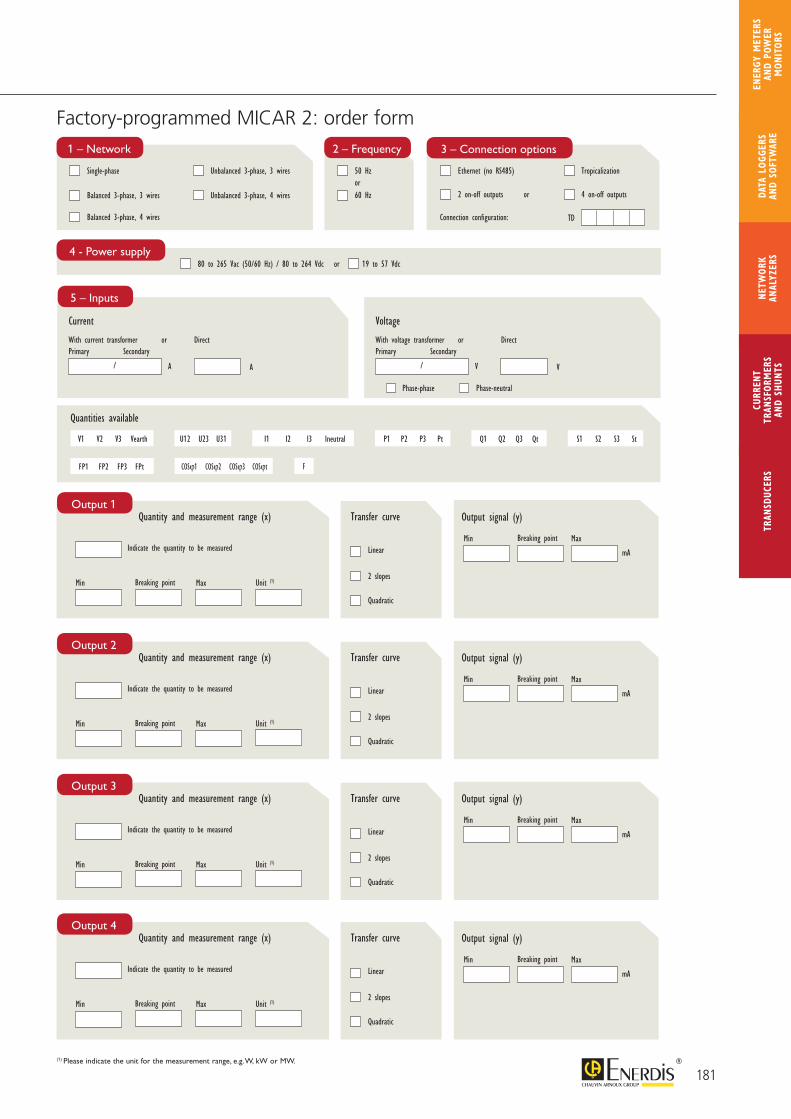
Factory-programmed MICAR 2: order form
(1) Please indicate the unit for the measurement range, e.g. W, kW or MW.
181
CURR
ENT
TRAN
SFOR
MER
SAN
D SH
UNTS
NETW
ORK
ANAL
YZER
STR
ANSD
UCER
SDA
TA L
OGGE
RS
AND
SOFT
WAR
E
ENER
GY M
ETER
S AN
D PO
WER
M
ONIT
ORS
Current
With current transformer or Direct
5 – Inputs
A A
/
Primary Secondary
Voltage
With voltage transformer or Direct
V V
/
Primary Secondary
Phase-phase Phase-neutral
4 - Power supply80 to 265 Vac (50/60 Hz) / 80 to 264 Vdc or 19 to 57 Vdc
1 – Network
Single-phase
Balanced 3-phase, 3 wires
Balanced 3-phase, 4 wires
Unbalanced 3-phase, 3 wires
Unbalanced 3-phase, 4 wires
3 – Connection options
Ethernet (no RS485)
2 on-off outputs or
Connection configuration:
Tropicalization
4 on-off outputs
Quantity and measurement range (x)
Min
Output signal (y)Transfer curve
Linear
2 slopes
Quadratic
Output 1
Breaking point Max Unit (1)
Indicate the quantity to be measured mA
Min Breaking point Max
TD
Quantity and measurement range (x)
Min
Output signal (y)Transfer curve
Linear
2 slopes
Quadratic
Output 2
Breaking point Max Unit (1)
Indicate the quantity to be measured mA
Min Breaking point Max
Quantity and measurement range (x)
Min
Output signal (y)Transfer curve
Linear
2 slopes
Quadratic
Output 3
Breaking point Max Unit (1)
Indicate the quantity to be measured mA
Min Breaking point Max
Quantity and measurement range (x)
Min
Output signal (y)Transfer curve
Linear
2 slopes
Quadratic
Output 4
Breaking point Max Unit (1)
Indicate the quantity to be measured mA
Min Breaking point Max
2 – Frequency
50 Hz
60 Hzor
V1 V2 V3 Vearth U12 U23 U31 I1 I2 I3 Ineutral P1 P2 P3 Pt Q1 Q2 Q3 Qt S1 S2 S3 St
FP1 FP2 FP3 FPt COSϕ1 COSϕ2 COSϕ3 COSϕt
Quantities available
F
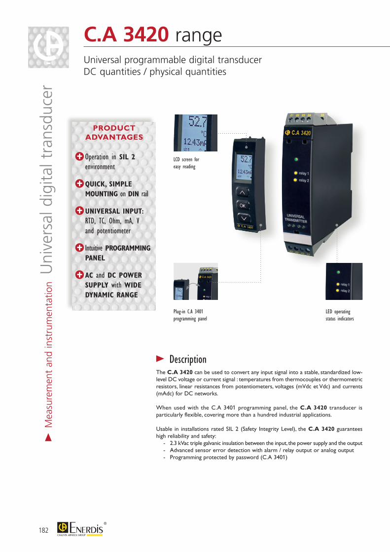
182
> DescriptionThe C.A 3420 can be used to convert any input signal into a stable, standardized low-level DC voltage or current signal : temperatures from thermocouples or thermometric resistors, linear resistances from potentiometers, voltages (mVdc et Vdc) and currents (mAdc) for DC networks.
When used with the C.A 3401 programming panel, the C.A 3420 transducer is particularly flexible, covering more than a hundred industrial applications.
Usable in installations rated SIL 2 (Safety Integrity Level), the C.A 3420 guarantees high reliability and safety: - 2.3 kVac triple galvanic insulation between the input, the power supply and the output - Advanced sensor error detection with alarm / relay output or analog output - Programming protected by password (C.A 3401)
Plug-in C.A 3401 programming panel
LED operating status indicators
LCD screen for easy reading
C.A 3420 range Universal programmable digital transducer DC quantities / physical quantities
Operation in SIL 2 environment
QUICK, SIMPLE MOUNTING on DIN rail
UNIVERSAL INPUT: RTD, TC, Ohm, mA, V and potentiometer
Intuitive PROGRAMMING PANEL
AC and DC POWER SUPPLY with WIDE DYNAMIC RANGE
> M
easu
rem
ent
and
inst
rum
enta
tion U
nive
rsal
dig
ital t
rans
duce
r
PRODUCT ADVANTAGES
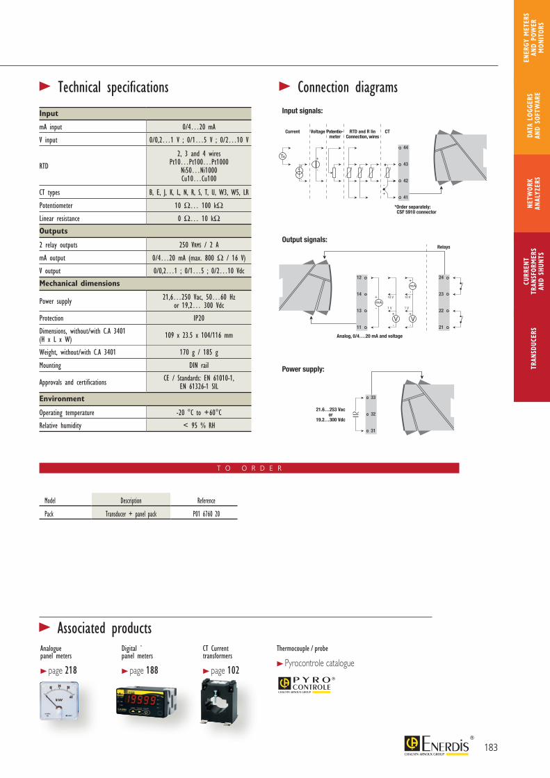
183
CURR
ENT
TRAN
SFOR
MER
SAN
D SH
UNTS
NETW
ORK
ANAL
YZER
STR
ANSD
UCER
SDA
TA L
OGGE
RS
AND
SOFT
WAR
E
ENER
GY M
ETER
S AN
D PO
WER
M
ONIT
ORS
Thermocouple / probe
> Pyrocontrole catalogue
T O O R D E R
Model Description Reference
Pack Transducer + panel pack P01 6760 20
Input
mA input 0/4…20 mA
V input 0/0,2…1 V ; 0/1…5 V ; 0/2…10 V
RTD
2, 3 and 4 wiresPt10…Pt100…Pt1000
Ni50…Ni1000Cu10…Cu100
CT types B, E, J, K, L, N, R, S, T, U, W3, W5, LR
Potentiometer 10 Ω… 100 kΩLinear resistance 0 Ω… 10 kΩOutputs
2 relay outputs 250 VRMS / 2 A
mA output 0/4…20 mA (max. 800 Ω / 16 V)
V output 0/0,2…1 ; 0/1…5 ; 0/2…10 Vdc
Mechanical dimensions
Power supply 21,6…250 Vac, 50…60 Hz or 19,2… 300 Vdc
Protection IP20
Dimensions, without/with C.A 3401 (H x L x W) 109 x 23.5 x 104/116 mm
Weight, without/with C.A 3401 170 g / 185 g
Mounting DIN rail
Approvals and certifications CE / Standards: EN 61010-1, EN 61326-1 SIL
Environment
Operating temperature -20 °C to +60°C
Relative humidity < 95 % RH
> Technical specifications > Connection diagramsInput signals:
Current RTD and R linConnection, wires
Relays
CT
*Order separately: CSF 5910 connector
Analog, 0/4….20 mA and voltage
21.6…253 Vacor
19.2…300 Vdc
Voltage Potentio-meter
Output signals:
Power supply:
Analogue panel meters
> page 218
Digital `panel meters
> page 188
CT Current transformers
> page 102
> Associated products
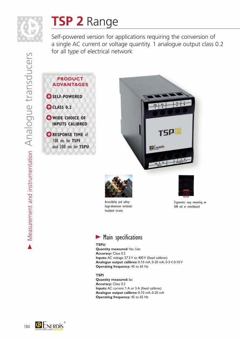
184
TSP 2 RangeSelf-powered version for applications requiring the conversion of a single AC current or voltage quantity. 1 analogue output class 0.2 for all type of electrical network
> M
easu
rem
ent
and
inst
rum
enta
tion A
nalo
gue
tran
sduc
ers
TSPUQuantity measured: Vac, UacAccuracy: Class 0.2Inputs: AC voltage: 57.5 V to 400 V (fixed calibres)Analogue output calibres: 0-10 mA, 0-20 mA, 0-5 V, 0-10 VOperating frequency: 45 to 65 Hz
TSPIQuantity measured: IacAccuracy: Class 0.2Inputs: AC current: 1 A or 5 A (fixed calibres)Analogue output calibres: 0-10 mA, 0-20 mAOperating frequency: 45 to 65 Hz
> Main specifications
Accessibility and safety: large-dimension terminalsInsulated circuits
Ergonomic: easy mounting on DIN rail or switchboard
PRODUCT ADVANTAGES
SELF-POWERED
CLASS 0.2
WIDE CHOICE OF INPUTS CALIBRED
RESPONSE TIME of 100 ms for TSPI and 200 ms for TSPU
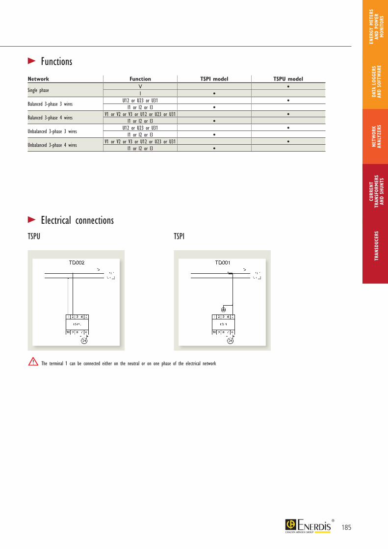
TSPU TSPI
The terminal 1 can be connected either on the neutral or on one phase of the electrical network
Network Function TSPI model TSPU model
Single phaseV •I •
Balanced 3-phase 3 wiresU12 or U23 or U31 •
I1 or I2 or I3 •Balanced 3-phase 4 wires
V1 or V2 or V3 or U12 or U23 or U31 •I1 or I2 or I3 •
Unbalanced 3-phase 3 wiresU12 or U23 or U31 •
I1 or I2 or I3 •Unbalanced 3-phase 4 wires
V1 or V2 or V3 or U12 or U23 or U31 •I1 or I2 or I3 •
> Electrical connections
> Functions
185
CURR
ENT
TRAN
SFOR
MER
SAN
D SH
UNTS
NETW
ORK
ANAL
YZER
STR
ANSD
UCER
SDA
TA L
OGGE
RS
AND
SOFT
WAR
E
ENER
GY M
ETER
S AN
D PO
WER
M
ONIT
ORS
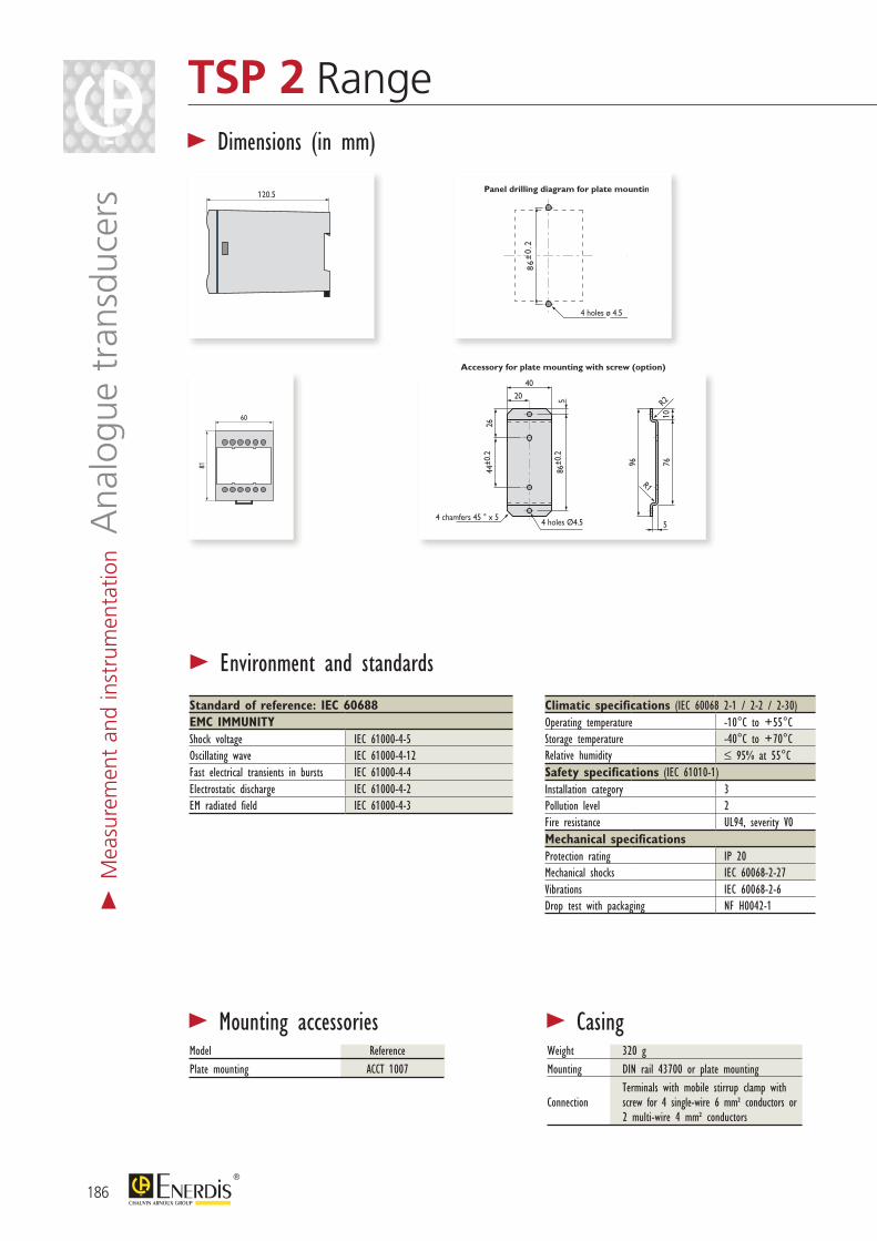
186
TSP 2 Range>
Mea
sure
men
t an
d in
stru
men
tatio
n Ana
logu
e tr
ansd
ucer
s
20
4 chamfers 45 ° x 5 4 holes Ø4.5
R1
R2
40
86±0
.25
7610
2644
±0.2
96
5
86
±0
.2
86
±0
.2
T11, TSPI et TSPU
Panel drilling diagram for plate mounting
Accessory for plate mounting with screw (option)
T12, T13, T21, T22, T23, T31, T32 et T33T11, TSPU et TSPI
T12, T13, T21, T22, T23, T31, T32 et T33
4 holes ø 4.5
70±0.2
60 120
120.5
8181
> Dimensions (in mm)
> Environment and standards
Standard of reference: IEC 60688EMC IMMUNITYShock voltage IEC 61000-4-5Oscillating wave IEC 61000-4-12Fast electrical transients in bursts IEC 61000-4-4Electrostatic discharge IEC 61000-4-2 EM radiated field IEC 61000-4-3
Climatic specifications (IEC 60068 2-1 / 2-2 / 2-30) Operating temperature -10°C to +55°CStorage temperature -40°C to +70°CRelative humidity ≤ 95% at 55°CSafety specifications (IEC 61010-1)Installation category 3Pollution level 2Fire resistance UL94, severity V0Mechanical specificationsProtection rating IP 20Mechanical shocks IEC 60068-2-27Vibrations IEC 60068-2-6Drop test with packaging NF H0042-1
> Mounting accessoriesModel ReferencePlate mounting ACCT 1007
> CasingWeight 320 gMounting DIN rail 43700 or plate mounting Terminals with mobile stirrup clamp with Connection screw for 4 single-wire 6 mm² conductors or 2 multi-wire 4 mm² conductors
20
4 chamfers 45 ° x 5 4 holes Ø4.5
R1
R2
40
86±0
.25
7610
2644
±0.2
96
5
86
±0
.2
86
±0
.2
T11, TSPI et TSPU
Panel drilling diagram for plate mounting
Accessory for plate mounting with screw (option)
T12, T13, T21, T22, T23, T31, T32 et T33T11, TSPU et TSPI
T12, T13, T21, T22, T23, T31, T32 et T33
4 holes ø 4.5
70±0.2
60 120
120.5
8181
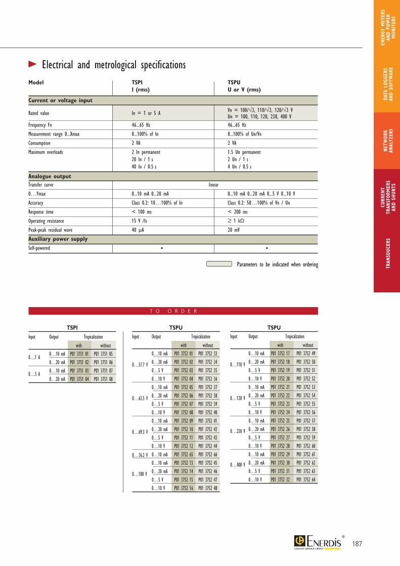
187
CURR
ENT
TRAN
SFOR
MER
SAN
D SH
UNTS
NETW
ORK
ANAL
YZER
STR
ANSD
UCER
SDA
TA L
OGGE
RS
AND
SOFT
WAR
E
ENER
GY M
ETER
S AN
D PO
WER
M
ONIT
ORS
T O O R D E R
Input Output Tropicalization
with without 0…10 mA P01 3752 17 P01 3752 49
0…110 V 0…20 mA P01 3752 18 P01 3752 50 0…5 V P01 3752 19 P01 3752 51 0…10 V P01 3752 20 P01 3752 52 0…10 mA P01 3752 21 P01 3752 53
0…120 V 0…20 mA P01 3752 22 P01 3752 54 0…5 V P01 3752 23 P01 3752 55 0…10 V P01 3752 24 P01 3752 56 0…10 mA P01 3752 25 P01 3752 57
0…230 V 0…20 mA P01 3752 26 P01 3752 58 0…5 V P01 3752 27 P01 3752 59 0…10 V P01 3752 28 P01 3752 60 0…10 mA P01 3752 29 P01 3752 61
0…400 V 0…20 mA P01 3752 30 P01 3752 62 0…5 V P01 3752 31 P01 3752 63 0…10 V P01 3752 32 P01 3752 64
Input Output Tropicalization
with without
0…1 A 0…10 mA P01 3751 01 P01 3751 05 0…20 mA P01 3751 02 P01 3751 06
0…5 A 0…10 mA P01 3751 03 P01 3751 07 0…20 mA P01 3751 04 P01 3751 08
Input Output Tropicalization
with without 0…10 mA P01 3752 01 P01 3752 33
0…57.7 V 0…20 mA P01 3752 02 P01 3752 34 0…5 V P01 3752 03 P01 3752 35 0…10 V P01 3752 04 P01 3752 36 0…10 mA P01 3752 05 P01 3752 37
0…63.5 V 0…20 mA P01 3752 06 P01 3752 38 0…5 V P01 3752 07 P01 3752 39 0…10 V P01 3752 08 P01 3752 40 0…10 mA P01 3752 09 P01 3752 41
0…69.3 V 0…20 mA P01 3752 10 P01 3752 42 0…5 V P01 3752 11 P01 3752 43 0…10 V P01 3752 12 P01 3752 44
0…76.2 V 0…10 mA P01 3752 65 P01 3752 66 0…10 mA P01 3752 13 P01 3752 45
0…100 V 0…20 mA P01 3752 14 P01 3752 46 0…5 V P01 3752 15 P01 3752 47 0…10 V P01 3752 16 P01 3752 48
TSPI TSPU TSPU
Model TSPI TSPU I (rms) U or V (rms)
Current or voltage input
Rated value In = 1 or 5 A Vn = 100/√3, 110/√3, 120/√3 V
Un = 100, 110, 120, 230, 400 VFrequency Fn 46...65 Hz 46...65 Hz
Measurement range 0...Xmax 0...100% of In 0...100% of Un/Vn
Consumption 2 VA 2 VA
Maximum overloads 2 In permanent 1.5 Un permanent 20 In / 1 s 2 Un / 1 s 40 In / 0.5 s 4 Un / 0.5 s
Analogue outputTransfer curve linear
0…Ymax 0...10 mA 0...20 mA 0...10 mA 0...20 mA 0...5 V 0...10 V
Accuracy Class 0.2: 10…100% of In Class 0.2: 50…100% of Vn / Un
Response time < 100 ms < 200 ms
Operating resistance 15 V /Is ≥ 1 kΩ
Peak-peak residual wave 40 μA 20 mV
Auxiliary power supply
Self-powered • •
Parameters to be indicated when ordering
> Electrical and metrological specifications
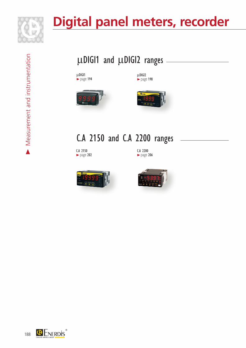
C.A 2150 and C.A 2200 rangesC.A 2150 > page 202
C.A 2200 > page 206
μDIGI1 and μDIGI2 rangesμDIGI1 > page 194
μDIGI2 > page 198
188
Digital panel meters, recorder and synchrocoupler>
Mea
sure
men
t an
d in
stru
men
tatio
n
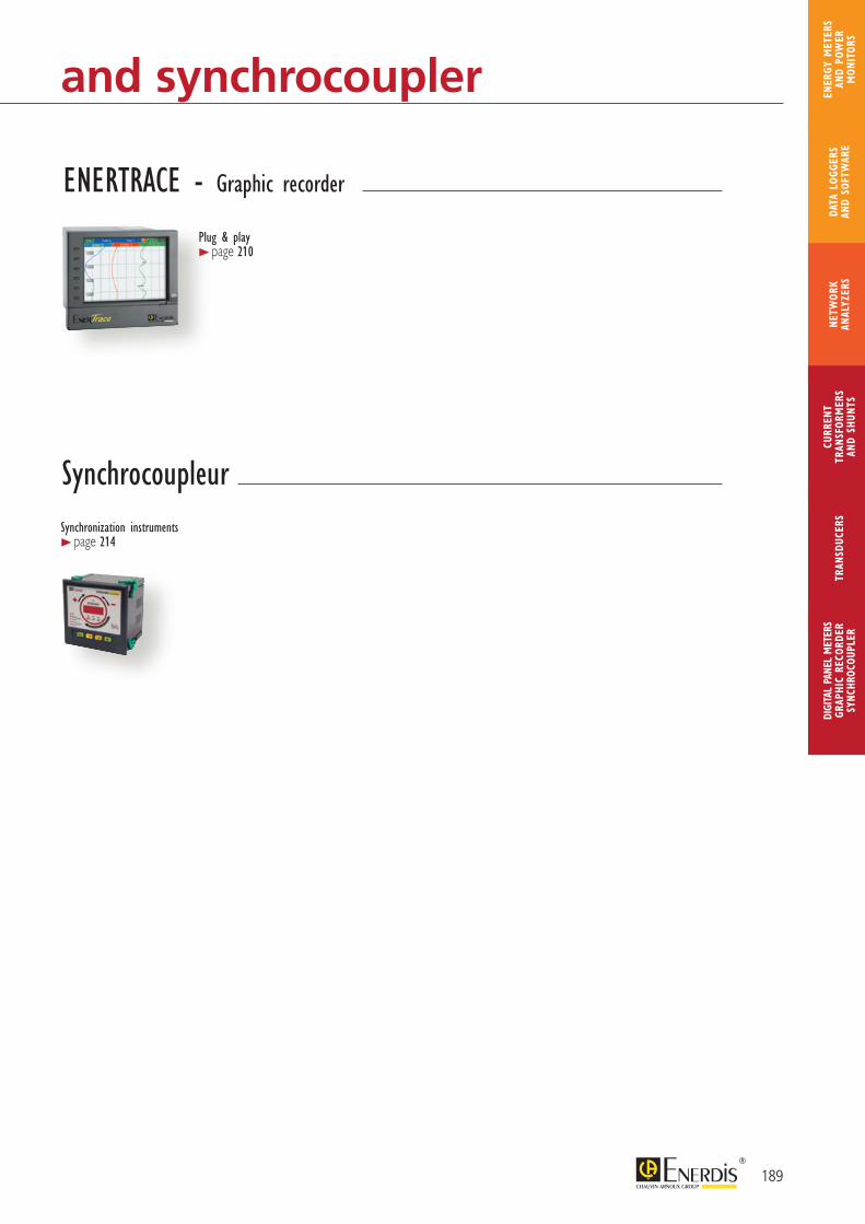
SynchrocoupleurSynchronization instruments > page 214
Plug & play > page 210
ENERTRACE - Graphic recorder
189
CURR
ENT
TRAN
SFOR
MER
SAN
D SH
UNTS
DIGI
TAL
PANE
L M
ETER
SGR
APHI
C RE
CORD
ERSY
NCHR
OCOU
PLER
NETW
ORK
ANAL
YZER
STR
ANSD
UCER
SDA
TA L
OGGE
RS
AND
SOFT
WAR
E
ENER
GY M
ETER
S AN
D PO
WER
M
ONIT
ORS
Digital panel meters, recorder and synchrocoupler
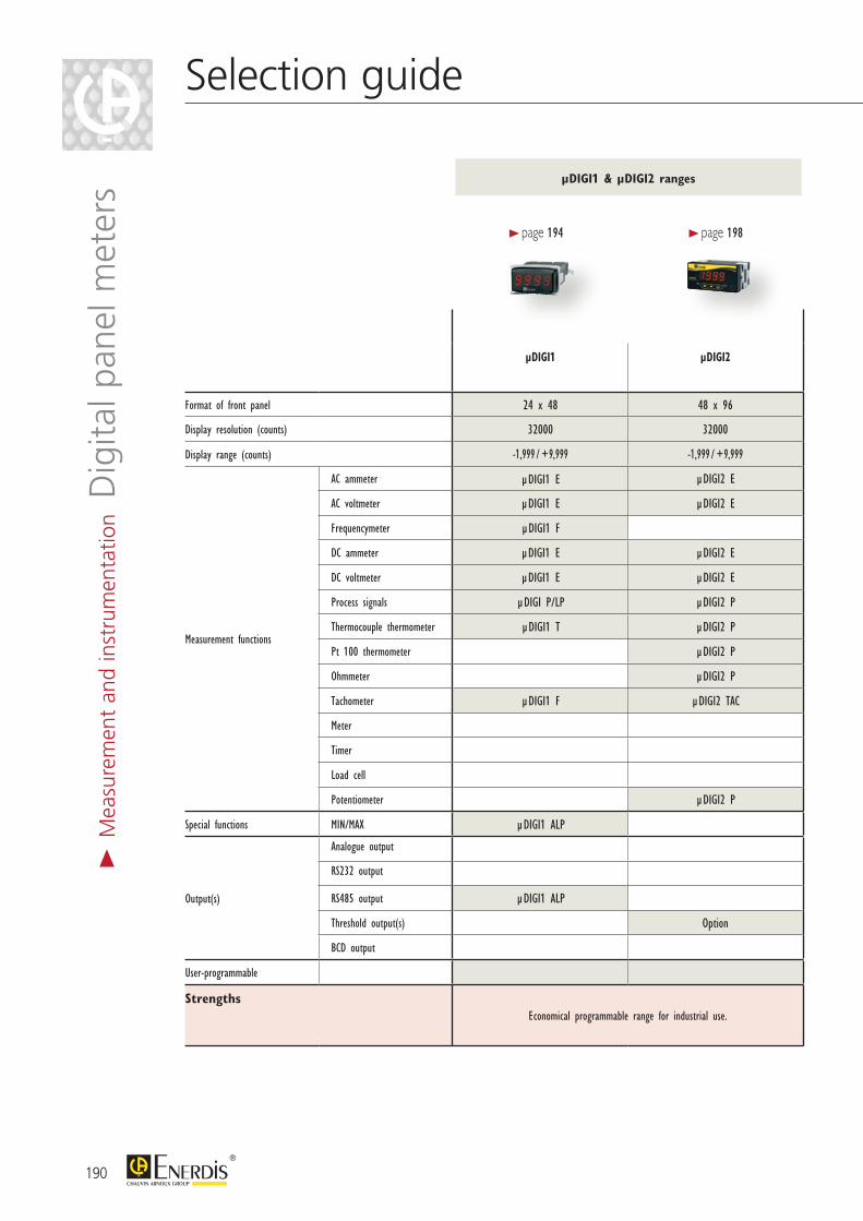
µDIGI1 µDIGI2 CA 2150 CA 2200
Format of front panel 24 x 48 48 x 96 48 x 96 48 x 96
Display resolution (counts) 32000 32000 32000 65000
Display range (counts) -1,999 / +9,999 -1,999 / +9,999 -19,999 / +19,999 -32,000 / +32,000
Measurement functions
AC ammeter µDIGI1 E µDIGI2 E C.A 2150-E
AC voltmeter µDIGI1 E µDIGI2 E C.A 2150-E
Frequencymeter µDIGI1 F C.A 2150-D C.A 2200-D
DC ammeter µDIGI1 E µDIGI2 E C.A 2150-E
DC voltmeter µDIGI1 E µDIGI2 E C.A 2150-E
Process signals µDIGI P/LP µDIGI2 P C.A 2150-M C.A 2200-P
Thermocouple thermometer µDIGI1 T µDIGI2 P C.A 2150-M C.A 2200-T
Pt 100 thermometer µDIGI2 P C.A 2150-M C.A 2200-T
Ohmmeter µDIGI2 P
Tachometer µDIGI1 F µDIGI2 TAC C.A 2150-D C.A 2200-D
Meter C.A 2150-D C.A 2200-D
Timer C.A 2150-D C.A 2200-D
Load cell C.A 2150-M C.A 2200-C
Potentiometer µDIGI2 P C.A 2150-M C.A 2200-P
Special functions MIN/MAX µDIGI1 ALP
Output(s)
Analogue output Option Option
RS232 output Option Option
RS485 output µDIGI1 ALP Option Option
Threshold output(s) Option Option Option
BCD output Option
User-programmable
StrengthsEconomical programmable range for industrial use. Programmable range for universal use.
µDIGI1 & µDIGI2 ranges
> page 194 > page 198
190
Selection guide>
Mea
sure
men
t an
d in
stru
men
tatio
n Dig
ital p
anel
met
ers
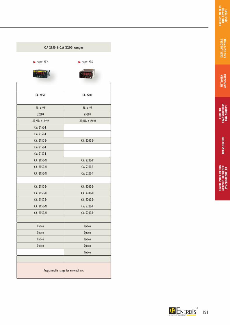
µDIGI1 µDIGI2 CA 2150 CA 2200
Format of front panel 24 x 48 48 x 96 48 x 96 48 x 96
Display resolution (counts) 32000 32000 32000 65000
Display range (counts) -1,999 / +9,999 -1,999 / +9,999 -19,999 / +19,999 -32,000 / +32,000
Measurement functions
AC ammeter µDIGI1 E µDIGI2 E C.A 2150-E
AC voltmeter µDIGI1 E µDIGI2 E C.A 2150-E
Frequencymeter µDIGI1 F C.A 2150-D C.A 2200-D
DC ammeter µDIGI1 E µDIGI2 E C.A 2150-E
DC voltmeter µDIGI1 E µDIGI2 E C.A 2150-E
Process signals µDIGI P/LP µDIGI2 P C.A 2150-M C.A 2200-P
Thermocouple thermometer µDIGI1 T µDIGI2 P C.A 2150-M C.A 2200-T
Pt 100 thermometer µDIGI2 P C.A 2150-M C.A 2200-T
Ohmmeter µDIGI2 P
Tachometer µDIGI1 F µDIGI2 TAC C.A 2150-D C.A 2200-D
Meter C.A 2150-D C.A 2200-D
Timer C.A 2150-D C.A 2200-D
Load cell C.A 2150-M C.A 2200-C
Potentiometer µDIGI2 P C.A 2150-M C.A 2200-P
Special functions MIN/MAX µDIGI1 ALP
Output(s)
Analogue output Option Option
RS232 output Option Option
RS485 output µDIGI1 ALP Option Option
Threshold output(s) Option Option Option
BCD output Option
User-programmable
StrengthsEconomical programmable range for industrial use. Programmable range for universal use.
C.A 2150 & C.A 2200 ranges
> page 202 > page 206
191
CURR
ENT
TRAN
SFOR
MER
SAN
D SH
UNTS
DIGI
TAL
PANE
L M
ETER
SGR
APHI
C RE
CORD
ERSY
NCHR
OCOU
PLER
NETW
ORK
ANAL
YZER
STR
ANSD
UCER
SDA
TA L
OGGE
RS
AND
SOFT
WAR
E
ENER
GY M
ETER
S AN
D PO
WER
M
ONIT
ORS
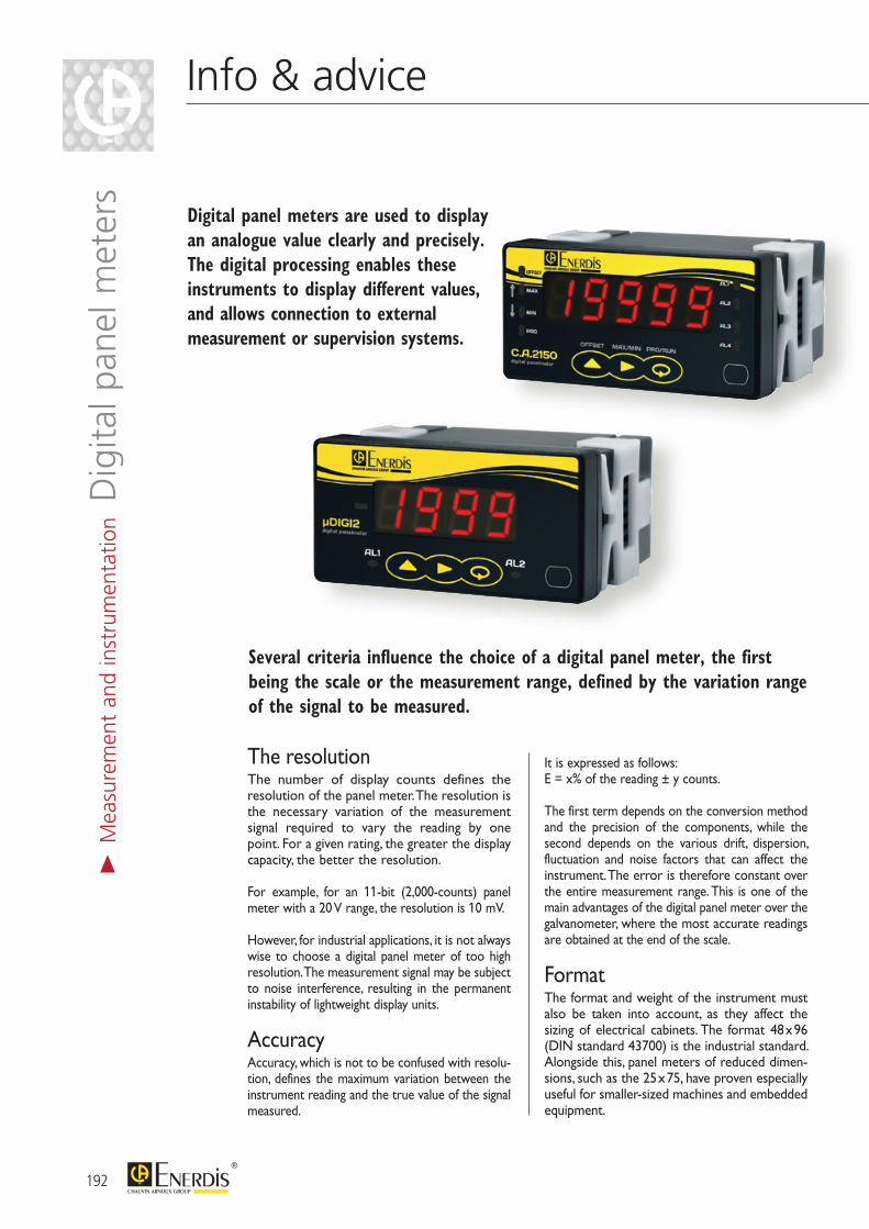
Info & advice
The resolutionThe number of display counts defines the resolution of the panel meter. The resolution is the necessary variation of the measurement signal required to vary the reading by one point. For a given rating, the greater the display capacity, the better the resolution.
For example, for an 11-bit (2,000-counts) panel meter with a 20 V range, the resolution is 10 mV.
However, for industrial applications, it is not always wise to choose a digital panel meter of too high resolution. The measurement signal may be subject to noise interference, resulting in the permanent instability of lightweight display units.
AccuracyAccuracy, which is not to be confused with resolu-tion, defines the maximum variation between the instrument reading and the true value of the signal measured.
It is expressed as follows: E = x% of the reading ± y counts.
The first term depends on the conversion method and the precision of the components, while the second depends on the various drift, dispersion, fluctuation and noise factors that can affect the instrument. The error is therefore constant over the entire measurement range. This is one of the main advantages of the digital panel meter over the galvanometer, where the most accurate readings are obtained at the end of the scale.
FormatThe format and weight of the instrument must also be taken into account, as they affect the sizing of electrical cabinets. The format 48 x 96 (DIN standard 43700) is the industrial standard. Alongside this, panel meters of reduced dimen-sions, such as the 25 x 75, have proven especially useful for smaller-sized machines and embedded equipment.
Several criteria influence the choice of a digital panel meter, the first being the scale or the measurement range, defined by the variation range of the signal to be measured.
Digital panel meters are used to display an analogue value clearly and precisely. The digital processing enables these instruments to display different values, and allows connection to external measurement or supervision systems.
> M
easu
rem
ent
and
inst
rum
enta
tion D
igita
l pan
el m
eter
s
192

>EnvironmentDigital panel meters, in general, are intended for indoor use, their electronic circuit being sensitive to difficult climatic environments (in contrast to analogue panel meters, which are suitable for both indoor and outdoor use). They must also support emissions stimulated and emitted by the electrical equipment.
>MaintenanceUnlike the analogue panel meter, the digital panel meter accepts low currents (maximum 600 V and 5 A). It therefore requires minimal precautions for the use of currents and voltages.
DisplayThe visibility of panel meter display characters is directly linked to the light difference between the digits and the screen background. LEDs, LCDs and backlit LCDs offer different levels of readability. LED technology, used on most of the ENERDIS range of digital panel meters, offers the best display contrast. A choice of red, green and amber colours also ensures they are easy to read.
Display only or multifunction products?Panel meters are increasingly universal, and must be able to display both strong signals, such as the voltage of a network, and weak signals such as process signals.
Instruments with multiple inputs, calibres and outputs are increasingly equipped with digital interfaces (RS232, RS485) for remote communi-cation, analogue outputs, and relay or alarm interfaces for connection to logic controllers.
Number of digits and display countsThe display of a digital panel meter is characterized by the number of digits. We speak, for example, of 3 1/2 digit or 4 3/4 digit panel meters.
A full digit has 10 possible states, in other words all values between 0 and 9.
A 1/2 digit has a maximum value of 1 and is capable of 2 states: 0 and 1.
A 3/4 digit can display a maximum value equal to 3 and has 4 states: 0, 1, 2, 3.
We can therefore expect a 3 1/2 digit panel meter to be capable of counting up to 2,000 (0 to 1,999), and a 4 3/4 digit panel meter to be capable of counting up to 40,000 (0 to 3,999). For this, the real display range of the apparatus must not be inferior.
How to get the best out of your panel meter
FO
CU
S
193
CURR
ENT
TRAN
SFOR
MER
SAN
D SH
UNTS
DIGI
TAL
PANE
L M
ETER
SGR
APHI
C RE
CORD
ERSY
NCHR
OCOU
PLER
NETW
ORK
ANAL
YZER
STR
ANSD
UCER
SDA
TA L
OGGE
RS
AND
SOFT
WAR
E
ENER
GY M
ETER
S AN
D PO
WER
M
ONIT
ORS
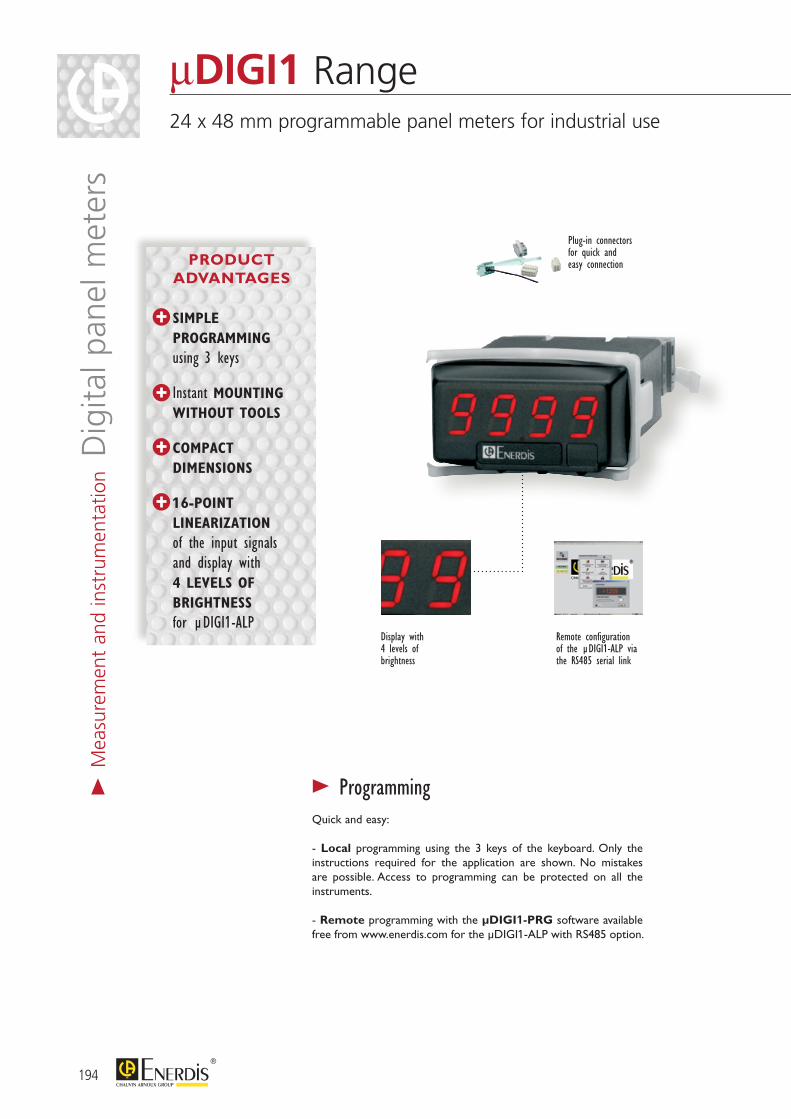
Remote configuration of the µDIGI1-ALP via the RS485 serial link
Display with 4 levels of brightness
Plug-in connectors for quick and easy connection
> ProgrammingQuick and easy:
- Local programming using the 3 keys of the keyboard. Only the instructions required for the application are shown. No mistakes are possible. Access to programming can be protected on all the instruments.
- Remote programming with the µDIGI1-PRG software available free from www.enerdis.com for the µDIGI1-ALP with RS485 option.
194
μDIGI1 Range24 x 48 mm programmable panel meters for industrial use
> M
easu
rem
ent
and
inst
rum
enta
tion D
igita
l pan
el m
eter
s
PRODUCT ADVANTAGES
SIMPLE PROGRAMMING using 3 keys
Instant MOUNTING WITHOUT TOOLS
COMPACT DIMENSIONS
16-POINT LINEARIZATION of the input signals and display with 4 LEVELS OF BRIGHTNESS for µDIGI1-ALP
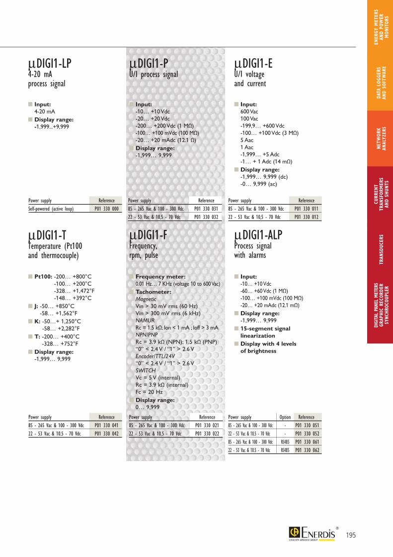
Input: 4-20 mA
Display range: -1,999...+9,999
μDIGI1-LP4-20 mAprocess signal
μDIGI1-PU/I process signal
μDIGI1-EU/I voltage and current
Power supply Reference85 - 265 Vac & 100 - 300 Vdc P01 330 03122 - 53 Vac & 10,5 - 70 Vdc P01 330 032
Power supply Reference85 - 265 Vac & 100 - 300 Vdc P01 330 01122 - 53 Vac & 10,5 - 70 Vdc P01 330 012
Power supply ReferenceSelf-powered (active loop) P01 330 000
Power supply Reference85 - 265 Vac & 100 - 300 Vdc P01 330 02122 - 53 Vac & 10.5 - 70 Vdc P01 330 022
Power supply Reference85 - 265 Vac & 100 - 300 Vdc P01 330 04122 - 53 Vac & 10.5 - 70 Vdc P01 330 042
Power supply Option Reference85 - 265 Vac & 100 - 300 Vdc - P01 330 05122 - 53 Vac & 10.5 - 70 Vdc - P01 330 05285 - 265 Vac & 100 - 300 Vdc RS485 P01 330 06122 - 53 Vac & 10.5 - 70 Vdc RS485 P01 330 062
Input: -10… +10 Vdc -20… +20 Vdc -200… +200 Vdc (1 MΩ) -100… +100 mVdc (100 MΩ) -20… +20 mAdc (12.1 Ω)
Display range: -1,999… 9,999
Input: 600 Vac 100 Vac -199,9… +600 Vdc -100… +100 Vdc (3 MΩ) 5 Aac 1 Aac -1,999… +5 Adc -1… + 1 Adc (14 mΩ)
Display range: -1,999… 9,999 (dc) -0… 9,999 (ac)
Pt100: -200… +800°C -100… +200°C -328… +1,472°F -148… +392°C
J: -50… +850°C -58… +1,562°F
K: -50…+ 1,250°C -58… +2,282°F
T: -200… +400°C -328… +752°F
Display range: -1,999… 9,999
μDIGI1-TTemperature (Pt100and thermocouple)
μDIGI1-FFrequency,rpm, pulse
μDIGI1-ALPProcess signalwith alarms
Frequency meter: 0.01 Hz… 7 KHz (voltage 10 to 600 Vac)
Tachometer: Magnetic Vin > 30 mV rms (60 Hz) Vin > 300 mV rms (6 kHz) NAMUR Rc = 1.5 kΩ; Ion < 1 mA ; Ioff > 3 mA NPN/PNP Rc = 3.9 kΩ (NPN); 1.5 kΩ (PNP) “0” < 2.4 V / “1” > 2.6 V Encoder/TTL/24V “0” < 2.4 V / “1” > 2.6 V SWITCH Vc = 5 V (internal) Rc = 3.9 kΩ (internal) Fc = 20 Hz
Display range: 0… 9,999
Input: -10… +10 Vdc -60… +60 Vdc (1 MΩ) -100… +100 mVdc (100 MΩ) -20… +20 mAdc (12.1 mΩ)
Display range: -1,999… 9,999
15-segment signal linearization
Display with 4 levels of brightness
195
CURR
ENT
TRAN
SFOR
MER
SAN
D SH
UNTS
DIGI
TAL
PANE
L M
ETER
SGR
APHI
C RE
CORD
ERSY
NCHR
OCOU
PLER
NETW
ORK
ANAL
YZER
STR
ANSD
UCER
SDA
TA L
OGGE
RS
AND
SOFT
WAR
E
ENER
GY M
ETER
S AN
D PO
WER
M
ONIT
ORS
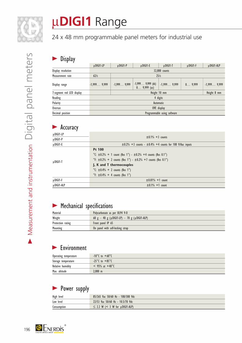
> Display µDIGI1-LP µDIGI1-P µDIGI1-E µDIGI1-T µDIGI1-F µDIGI1-ALPDisplay resolution 32,000 countsMeasurement rate 62/s 25/s
Display range -1,999… 9,999 -1,999… 9,999 -1,999… 9,999 (dc) -1,999… 9,999
0… 9,999 -1,999… 9,999 0… 9,999 (ac)7-segment red LED display Height 10 mm Height 8 mmReading 4 digits Polarity Automatic Overrun OVE display Decimal position Programmable using software
> Power supplyHigh level 85/265 Vac 50/60 Hz - 100/300 VdcLow level 22/53 Vac 50/60 Hz - 10.5/70 Vdc Consumption ≤ 2.2 W (< 3 W for µDIGI1-ALP)
> EnvironmentOperating temperature -10°C to +60°CStorage temperature -25°C to +85°CRelative humidity < 95% at +40°CMax. altitude 2,000 m
> Mechanical specificationsMaterial Polycarbonate as per UL94 V-O Weight 60 g – 40 g (µDIGI1-LP) – 70 g (µDIGI1-ALP) Protection rating Front panel IP 65 Mounting On panel with self-locking strap
> AccuracyµDIGI1-LP
±0.1% +3 countsµDIGI1-PµDIGI1-E ±0.2% +3 counts - ±0.4% +4 counts for 100 V/Aac inputs Pt 100 °C: ±0.2% + 1 count (Res 1°) - ±0.2% +4 counts (Res 0.1°)
µDIGI1-T °F: ±0.2% + 2 counts (Res 1°) - ±0.2% +7 counts (Res 0.1°) J, K and T thermocouples °C: ±0.4% + 2 counts (Res 1°) °F: ±0.4% + 4 counts (Res 1°)µDIGI1-F ±0.01% +1 countµDIGI1-ALP ±0.1% +1 count
196
μDIGI1 Range24 x 48 mm programmable panel meters for industrial use
> M
easu
rem
ent
and
inst
rum
enta
tion D
igita
l pan
el m
eter
s
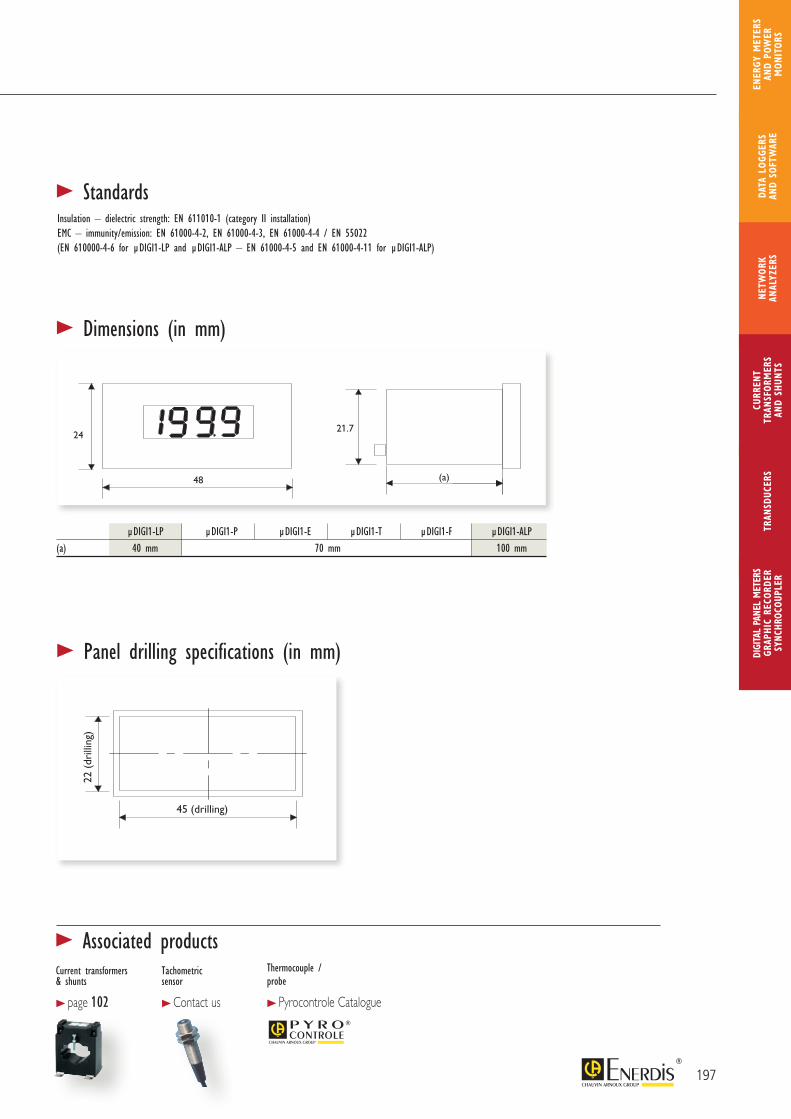
24
48
21.7
22 (
perç
age)
45 (perçage)(a)
24
48
21,7
22 (
drill
ing)
45 (drilling)(a)
> Dimensions (in mm)
> Panel drilling specifications (in mm)
> StandardsInsulation – dielectric strength: EN 611010-1 (category II installation)EMC – immunity/emission: EN 61000-4-2, EN 61000-4-3, EN 61000-4-4 / EN 55022(EN 610000-4-6 for µDIGI1-LP and µDIGI1-ALP – EN 61000-4-5 and EN 61000-4-11 for µDIGI1-ALP)
µDIGI1-LP µDIGI1-P µDIGI1-E µDIGI1-T µDIGI1-F µDIGI1-ALP(a) 40 mm 70 mm 100 mm
197
CURR
ENT
TRAN
SFOR
MER
SAN
D SH
UNTS
DIGI
TAL
PANE
L M
ETER
SGR
APHI
C RE
CORD
ERSY
NCHR
OCOU
PLER
NETW
ORK
ANAL
YZER
STR
ANSD
UCER
SDA
TA L
OGGE
RS
AND
SOFT
WAR
E
ENER
GY M
ETER
S AN
D PO
WER
M
ONIT
ORS
> Associated productsCurrent transformers & shunts
> page 102
Tachometric sensor
> Contact us
Thermocouple / probe
> Pyrocontrole Catalogue
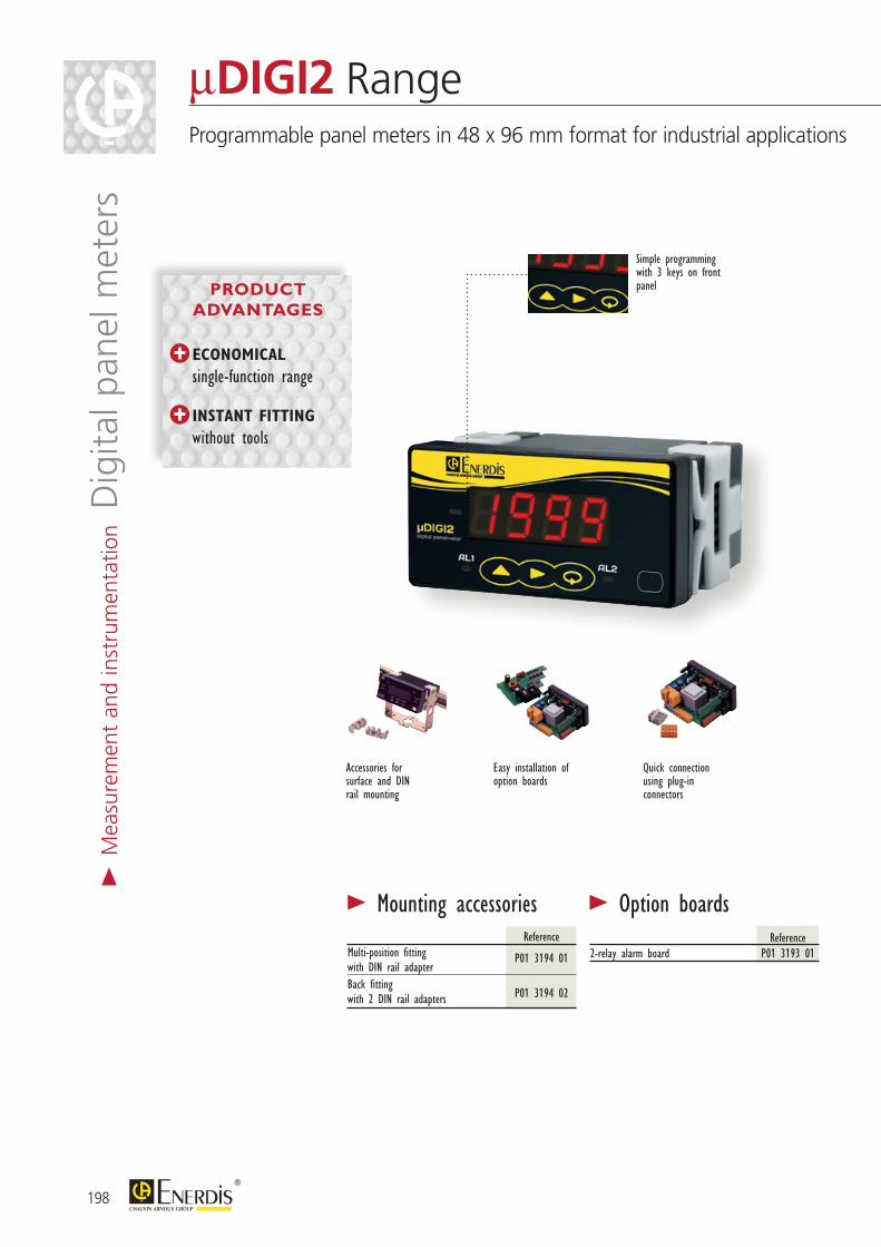
Easy installation of option boards
Accessories for surface and DIN rail mounting
Simple programming with 3 keys on front panel
> Mounting accessories ReferenceMulti-position fittingwith DIN rail adapter
P01 3194 01
Back fitting with 2 DIN rail adapters
P01 3194 02
> Option boards Reference2-relay alarm board P01 3193 01
Quick connection using plug-in connectors
198
μDIGI2 RangeProgrammable panel meters in 48 x 96 mm format for industrial applications
> M
easu
rem
ent
and
inst
rum
enta
tion D
igita
l pan
el m
eter
s
ECONOMICAL
single-function range
INSTANT FITTING
without tools
PRODUCT ADVANTAGES
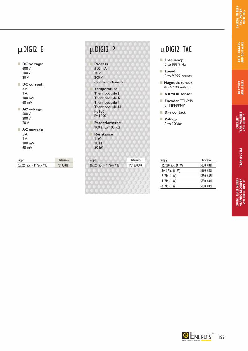
199
CURR
ENT
TRAN
SFOR
MER
SAN
D SH
UNTS
DIGI
TAL
PANE
L M
ETER
SGR
APHI
C RE
CORD
ERSY
NCHR
OCOU
PLER
NETW
ORK
ANAL
YZER
STR
ANSD
UCER
SDA
TA L
OGGE
RS
AND
SOFT
WAR
E
ENER
GY M
ETER
S AN
D PO
WER
M
ONIT
ORS
DC voltage: 600 V
200 V 20 V
DC current: 5 A
1 A 100 mV 60 mV
AC voltage: 600 V 200 V 20 V
AC current: 5 A
1 A 100 mV 60 mV
μDIGI2 E μDIGI2 TAC
Supply Reference20/265 Vac - 11/265 Vdc P01330081
Supply Reference115/230 Vac (3 VA) 5330 081F24/48 Vac (3 VA) 5330 082F12 Vdc (3 W) 5330 083F24 Vdc (3 W) 5330 084F48 Vdc (3 W) 5330 085F
Frequency: 0 to 999.9 Hz
Speed: 0 to 9,999 counts
Magnetic sensor: Vin > 120 mVrms
NAMUR sensor
Encoder TTL/24V or NPN/PNP
Dry contact
Voltage: 0 to 10 Vac
Process: ±20 mA
10 V 200 V dynamo-tachometer
Temperature: Thermocouple J
Thermocouple K Thermocouple T Thermocouple N Pt 100 Pt 1000
Potentiometer: 100 Ω to 100 kΩ
Resistance: 1 kΩ
10 kΩ 50 kΩ
μDIGI2 P
Supply Reference20/265 Vac - 11/265 Vdc P01330080
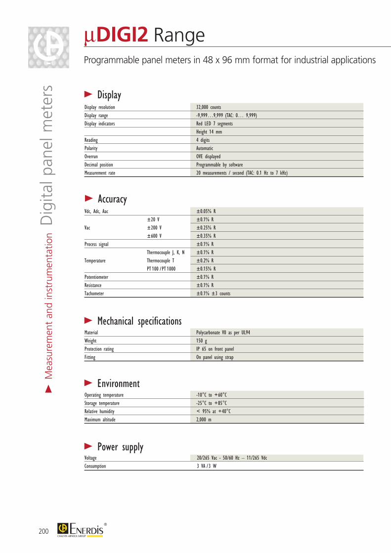
> Display
> Accuracy
> Power supply
> EnvironmentOperating temperature -10°C to +60°CStorage temperature -25°C to +85°CRelative humidity < 95% at +40°CMaximum altitude 2,000 m
> Mechanical specificationsMaterial Polycarbonate V0 as per UL94 Weight 150 g Protection rating IP 65 on front panel Fitting On panel using strap
200
μDIGI2 RangeProgrammable panel meters in 48 x 96 mm format for industrial applications
> M
easu
rem
ent
and
inst
rum
enta
tion D
igita
l pan
el m
eter
s
Vdc, Adc, Aac ±0.05% R ±20 V ±0.1% RVac ±200 V ±0.25% R ±600 V ±0.35% RProcess signal ±0.1% R Thermocouple J, K, N ±0.1% RTemperature Thermocouple T ±0.2% R PT 100 / PT 1000 ±0.15% RPotentiometer ±0.1% RResistance ±0.1% RTachometer ±0.1% ±3 counts
Voltage 20/265 Vac - 50/60 Hz – 11/265 Vdc Consumption 3 VA / 3 W
Display resolution 32,000 countsDisplay range -9,999…9,999 (TAC: 0… 9,999)Display indicators Red LED 7 segments Height 14 mm Reading 4 digits Polarity Automatic Overrun OVE displayed Decimal position Programmable by software Measurement rate 20 measurements / second (TAC: 0.1 Hz to 7 kHz)
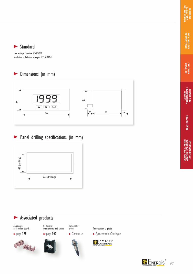
92 (drilling)
45 (
drill
ing)
92 (drilling)
45 (
drill
ing)
> Dimensions (in mm)
> Panel drilling specifications (in mm)
> StandardLow voltage directive 73/23/CEEInsulation - dielectric strength IEC 61010-1
201
CURR
ENT
TRAN
SFOR
MER
SAN
D SH
UNTS
DIGI
TAL
PANE
L M
ETER
SGR
APHI
C RE
CORD
ERSY
NCHR
OCOU
PLER
NETW
ORK
ANAL
YZER
STR
ANSD
UCER
SDA
TA L
OGGE
RS
AND
SOFT
WAR
E
ENER
GY M
ETER
S AN
D PO
WER
M
ONIT
ORS
> Associated productsAccessories and option boards
> page 198
CT Current transformers and shunts
> page 102
Tachometer probe
> Contact us
Thermocouple / probe
> Pyrocontrole Catalogue

Quick connection using plug-in connectors (spring-cage type)
Remote configuration via the RS232 or RS485 serial link
3 display colours
The C.A 2150-E is a programmable multi-rating panel meter which measures TRMS Vac or Iac quantities and Vdc or Idc quantities.
The C.A 2150-M is a 4-in-1 programmable panel meter which can be configured for process, temperature, load cell or potentiometer signals.
The C.A 2150-D is a 4-in-1 programmable panel meter which can be configured for the following applications: meter, tachometer, frequencymeter and chronometer.
The serial link can be used to transfer the measurements onto a PC.
The CA2150-PRG software, available free of charge from www.enerdis.com, can be used to read the measurement directly, configure and remotely program one or more con-nected panel meters.
It can also be used to save and recover the configuration of an existing panel meter.
> AccessoriesModel ReferenceMulti-position mounting with2 DIN rail adapters P01 3194 01
Connector + 1 m RS232 cable P01 3194 03Connector + 1 m RS485 cable P01 3194 04
> Option boards*Model ReferenceC.A 2XXX AL 2-relay board P01 3193 01C.A 2XXX AL 4-relay board P01 3193 03C.A 2XXX 4 NPN board P01 3193 04C.A 2XXX COM RS232 board P01 3193 06C.A 2XXX COM RS485 board P01 3193 07C.A 2150 0 – 10 V output board P01 3193 10C.A 2150 4 – 20 mA output board P01 3193 11
* Extra boards (addition or replacement)
> Description
202
> M
easu
rem
ent
and
inst
rum
enta
tion D
igita
l pan
el m
eter
sC.A 2150 Range48 x 96 mm programmable digital panel meters for all types of industrial applications
MULTI-FUNCTION PRODUCTS
3 DISPLAY COLOURS
4 ALARMS as standard
INSTANT MOUNTING WITHOUT TOOLS
SERIAL LINK for remote processing
of the measurements
PRODUCT ADVANTAGES
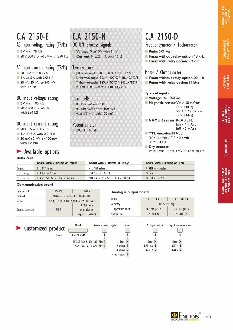
> Customized product
Type of link RS232C RS485Protocol ISO1745, C.A protocol or ModBus/RTUSpeed 1,200, 2,400, 4,800, 9,600 or 19,200 bauds RJ11-6 with Output connector RJ9-4 dual adapter (input + output)
Output 0… 10 V 4… 20 mAAccuracy 0.1% ±1 digitTemperature coeff. 0.2 mV per K 0.5 µA per KCharge maxi > 500 Ω < 800 Ω
Board with 2 alarms on relays Board with 4 alarms on relays Board with 4 alarms on NPN
Outputs 2 x 1RT relays 4 x 1RT relays 4 NPN optocouplersMax. voltage 250 Vac or 12 Vdc 250 Vac or 125 Vdc 50 VdcMax. current 8 A at 250 Vac or 8 A at 24 Vdc 500 mA at 125 Vac or 1 A at 30 Vdc 50 mA at 50 Vdc
> Available options
Communication board
Analogue output board
Model Auxiliary power supply Alarm Analogue output Digital communication
85-265 Vac & 100-300 Vdc: 122-53 Vac & 10.5-70 Vdc: 2
None: X RS232: 1 RS485: 2
None: X4-20 mA: 10-10 V: 2
None: X 2 relays: 1 4 relays: 2 4 transistors: 3
Example C.A 2150-M 1 X 1 1
Voltage: 0...±10 V with 1 mΩCurrent: 0...±20 mA with 15 Ω
Temperature J thermocouple: -50...+800°C / -58...+1472°F K thermocouple: -50...+1,200°C / -58...+2,192°F T thermocouple: -150...+400°C / -302...+752°FPt 100: -100...+800°C / -148...+1,472°F
Load cells0...±15 mV with 100 mΩ0...±30 mVdc with 100 mΩ0...±150 mV with 100 mΩ
Potentiometer200 Ω...100 kΩ
C.A 2150-MDC U/I process signals
C.A 2150-DFrequencymeter / Tachometer Fmin: 0.01 Hz Fmax without relay option: 19 kHzFmax with relay option: 9.9 kHz
Meter / Chronometer Fmax without relay option: 20 kHz Fmax with relay option: 15 kHz
Types of inputs: Voltage: 10…300 Vac Magnetic sensor: Vin > 60 mVrms
(F < 1 kHz) Vin > 120 mVrms (F > 1 kHz)
NAMUR sensor: Rc = 3.3 kΩ Ion < 1 mAdc Ioff > 3 mAdc
TTL encoder/24 Vdc: "0" < 2.4 Vdc / "1" > 2.6 Vdc Rc = 3.3 kΩ
Dry contact: Vc = 5 Vdc / Rc = 3.9 kΩ / Fc = 20 Hz
2 V with 75 kΩ20 V, 200 V or 600 V with 850 kΩ
AC input current rating (TRMS) 200 mA with 0.75 Ω 1 A or 5 A with 0,014 Ω 50 mV, 60 mV or 100 mV
with 1.5 MΩ
DC input voltage rating2 V with 100 kΩ20 V, 200 V or 600 V
with 850 kΩ
DC input current rating200 mA with 0.75 Ω1 A or 5 A with 0.014 Ω50 mV, 60 mV or 100 mV
with 1.8 MΩ
C.A 2150-EAC input voltage rating (TRMS)
Relay card
203
CURR
ENT
TRAN
SFOR
MER
SAN
D SH
UNTS
DIGI
TAL
PANE
L M
ETER
SGR
APHI
C RE
CORD
ERSY
NCHR
OCOU
PLER
NETW
ORK
ANAL
YZER
STR
ANSD
UCER
SDA
TA L
OGGE
RS
AND
SOFT
WAR
E
ENER
GY M
ETER
S AN
D PO
WER
M
ONIT
ORS
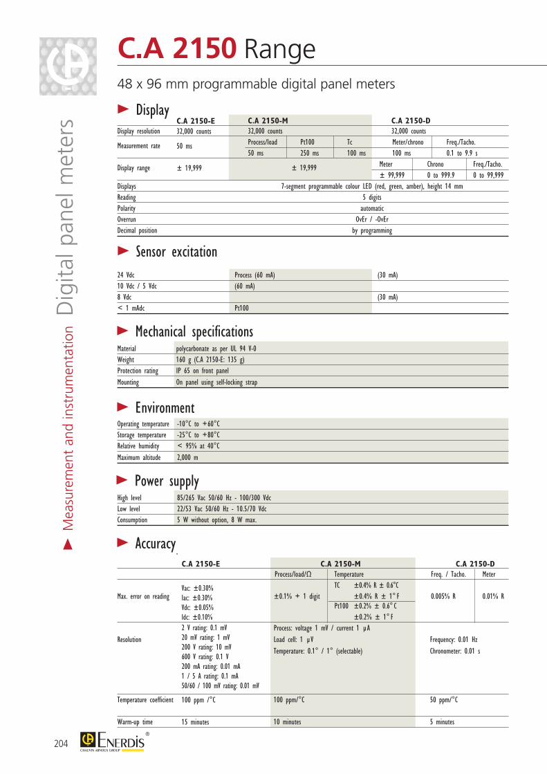
> Display C.A 2150-M C.A 2150-DDisplay resolution 32,000 counts 32,000 counts
Measurement rate Process/load Pt100 Tc Meter/chrono Freq./Tacho. 50 ms 250 ms 100 ms 100 ms 0.1 to 9.9 s
Display range ± 19,999 Meter Chrono Freq./Tacho. ± 99,999 0 to 999.9 0 to 99,999Displays 7-segment programmable colour LED (red, green, amber), height 14 mm Reading 5 digits Polarity automatic Overrun OvEr / -OvEr Decimal position by programming
24 Vdc Process (60 mA) (30 mA)10 Vdc / 5 Vdc (60 mA)8 Vdc (30 mA)< 1 mAdc Pt100
> Sensor excitation
Material polycarbonate as per UL 94 V-0Weight 160 g (C.A 2150-E: 135 g) Protection rating IP 65 on front panel Mounting On panel using self-locking strap
> Mechanical specifications
Operating temperature -10°C to +60°CStorage temperature -25°C to +80°C Relative humidity < 95% at 40°C Maximum altitude 2,000 m
> Environment
High level 85/265 Vac 50/60 Hz - 100/300 Vdc Low level 22/53 Vac 50/60 Hz - 10.5/70 Vdc Consumption 5 W without option, 8 W max.
> Power supply
> Accuracy
Vac: ±0.30% Iac: ±0.30% Vdc: ±0.05%Idc: ±0.10% 2 V rating: 0.1 mV20 mV rating: 1 mV200 V rating: 10 mV600 V rating: 0.1 V200 mA rating: 0.01 mA1 / 5 A rating: 0.1 mA50/60 / 100 mV rating: 0.01 mV
100 ppm /°C
15 minutes
C.A 2150-E C.A 2150-M C.A 2150-D Process/load/Ω Temperature Freq. / Tacho. Meter TC ±0.4% R ± 0.6°CMax. error on reading ±0.1% + 1 digit ±0.4% R ± 1° F 0.005% R 0.01% R Pt100 ±0.2% ± 0.6° C ±0.2% ± 1° F Process: voltage 1 mV / current 1 µA Resolution Load cell: 1 µV Frequency: 0.01 Hz Temperature: 0.1° / 1° (selectable) Chronometer: 0.01 s
Temperature coefficient 100 ppm/°C 50 ppm/°C Warm-up time 10 minutes 5 minutes
C.A 2150-E32,000 counts
50 ms
± 19,999
204
C.A 2150 Range48 x 96 mm programmable digital panel meters
> M
easu
rem
ent
and
inst
rum
enta
tion D
igita
l pan
el m
eter
s
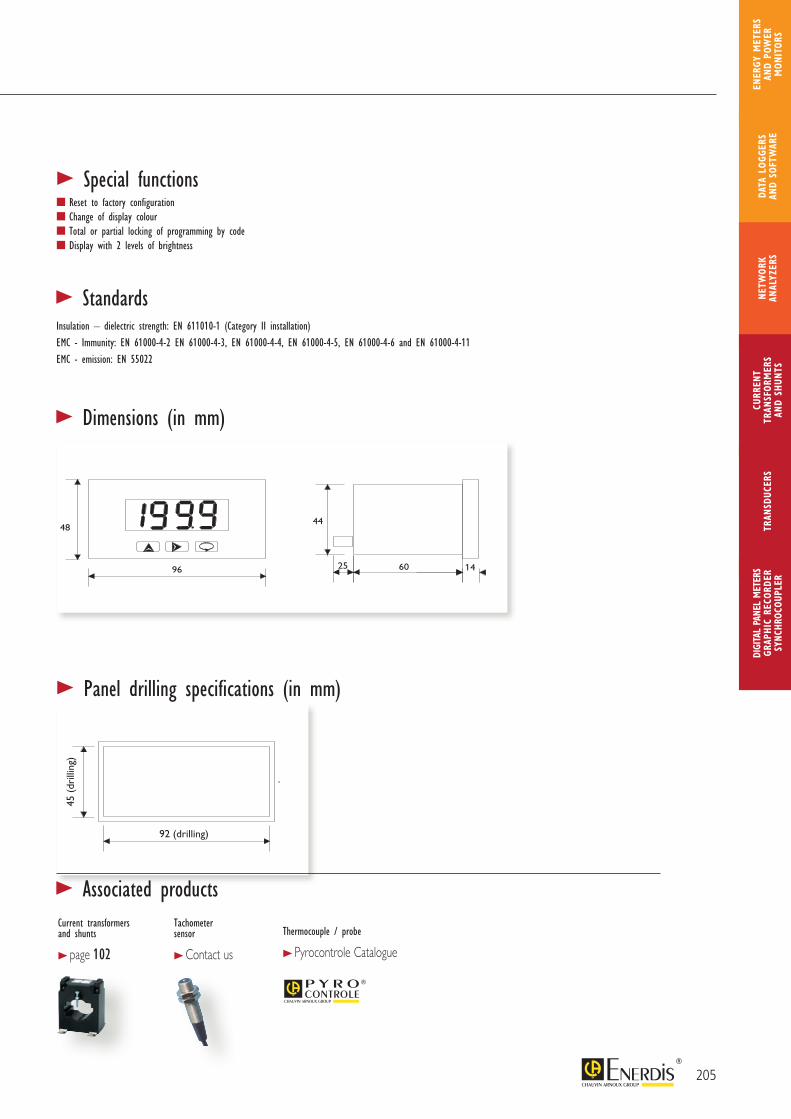
92 (drilling)
45 (
drill
ing)
92 (drilling)
45 (
drill
ing)
> StandardsInsulation – dielectric strength: EN 611010-1 (Category II installation)EMC - Immunity: EN 61000-4-2 EN 61000-4-3, EN 61000-4-4, EN 61000-4-5, EN 61000-4-6 and EN 61000-4-11EMC - emission: EN 55022
> Special functionsReset to factory configurationChange of display colourTotal or partial locking of programming by codeDisplay with 2 levels of brightness
> Dimensions (in mm)
> Panel drilling specifications (in mm)
205
CURR
ENT
TRAN
SFOR
MER
SAN
D SH
UNTS
DIGI
TAL
PANE
L M
ETER
SGR
APHI
C RE
CORD
ERSY
NCHR
OCOU
PLER
NETW
ORK
ANAL
YZER
STR
ANSD
UCER
SDA
TA L
OGGE
RS
AND
SOFT
WAR
E
ENER
GY M
ETER
S AN
D PO
WER
M
ONIT
ORS
> Associated productsCurrent transformers and shunts
> page 102
Tachometer sensor
> Contact us
Thermocouple / probe
> Pyrocontrole Catalogue

Quick connection using plug-in connectors
Very simple installation of option boards
Accessories for surface or DIN rail mounting
Simple programming using 5 keys on front panel
On the 4 instruments, two digital filters can be activated to stabilize the display of measurements depending on the processing conditions.
The measurement display can be disabled remotely by closing a contact. The display and reset of MAX and MIN values can also be activated remotely.
On the C.A 2200-P and C.A 2200-C, activation and cancellation of the OFFSET function can also be controlled remotely. The OFFSET command functions may be modified by the user, with 26 functions in all being pre-programmed on the instruments.
On the C.A 2200-P and C.A 2200-C models, the display can also be set to flashing mode to indicate an alarm threshold overrun.
> Description
> AccessoriesModel ReferenceMulti-position fittingwith 2 DIN rail adapters P01 3194 01
Rear fitting with 2 DIN rail adapters P01 3194 02
Connector + 1 m RS232 cable P01 3194 03Connector + 1 m RS485 cable P01 3194 04Kit of 4 x C.A 2200 screw connectors P01 3194 06
> Option boards*Model ReferenceC.A 2XXX AL 2-relay board P01 3193 01C.A 2XXX AL 4-relay board P01 3193 03C.A 2XXX 4 NPN board P01 3193 04C.A 2200 analogue output board P01 3193 05C.A 2200 BCD output board P01 3193 08C.A 2XXX COM RS232 board P01 3193 06C.A 2XXX COM RS485 board P01 3193 07
* Extra boards (addition or replacement)206
C.A 2200 Range48 x 96 mm programmable digital panel meters for universal use
> M
easu
rem
ent
and
inst
rum
enta
tion D
igita
l pan
el m
eter
s
PRODUCT ADVANTAGES
RECORDING of maximum and
minimum values of input variable
SERIAL LINK for remote processing
of measurements
LINEARIZATION of input signal over 11 segments
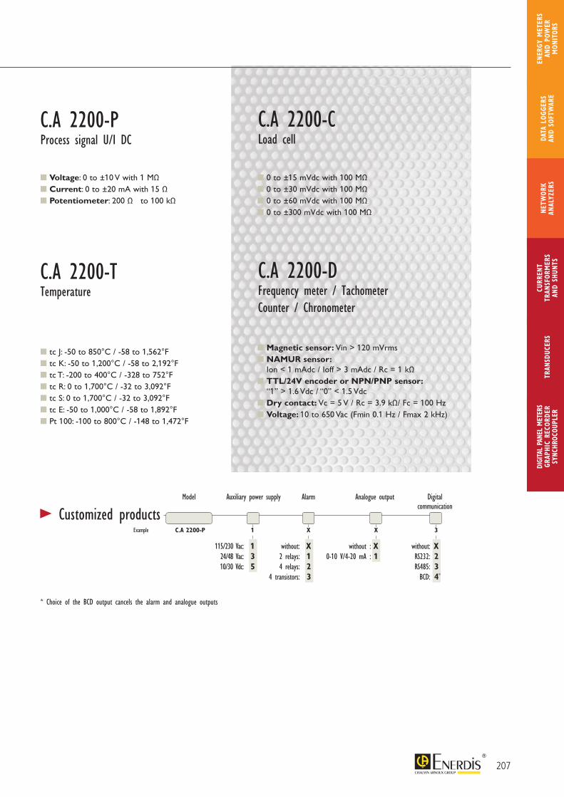
> Customized products
Voltage: 0 to ±10 V with 1 MΩCurrent: 0 to ±20 mA with 15 ΩPotentiometer: 200 Ω to 100 kΩ
0 to ±15 mVdc with 100 MΩ0 to ±30 mVdc with 100 MΩ0 to ±60 mVdc with 100 MΩ 0 to ±300 mVdc with 100 MΩ
C.A 2200-PProcess signal U/I DC
C.A 2200-CLoad cell
C.A 2200-DFrequency meter / TachometerCounter / Chronometer
tc J: -50 to 850°C / -58 to 1,562°F tc K: -50 to 1,200°C / -58 to 2,192°F tc T: -200 to 400°C / -328 to 752°F tc R: 0 to 1,700°C / -32 to 3,092°F tc S: 0 to 1,700°C / -32 to 3,092°F tc E: -50 to 1,000°C / -58 to 1,892°FPt 100: -100 to 800°C / -148 to 1,472°F
C.A 2200-TTemperature
Magnetic sensor: Vin > 120 mVrms NAMUR sensor:
Ion < 1 mAdc / Ioff > 3 mAdc / Rc = 1 kΩ TTL/24V encoder or NPN/PNP sensor:
“1” > 1.6 Vdc / “0” < 1.5 Vdc Dry contact: Vc = 5 V / Rc = 3.9 kΩ/ Fc = 100 Hz Voltage: 10 to 650 Vac (Fmin 0.1 Hz / Fmax 2 kHz)
Model Auxiliary power supply Alarm Analogue output Digital communication
115/230 Vac: 1 24/48 Vac: 3 10/30 Vdc: 5
C.A 2200-P 1 X X 3
without: X RS232: 2 RS485: 3 BCD: 4
without: X 2 relays: 1 4 relays: 2 4 transistors: 3
Example
* Choice of the BCD output cancels the alarm and analogue outputs
*
without : X 0-10 V/4-20 mA : 1
207
CURR
ENT
TRAN
SFOR
MER
SAN
D SH
UNTS
DIGI
TAL
PANE
L M
ETER
SGR
APHI
C RE
CORD
ERSY
NCHR
OCOU
PLER
NETW
ORK
ANAL
YZER
STR
ANSD
UCER
SDA
TA L
OGGE
RS
AND
SOFT
WAR
E
ENER
GY M
ETER
S AN
D PO
WER
M
ONIT
ORS
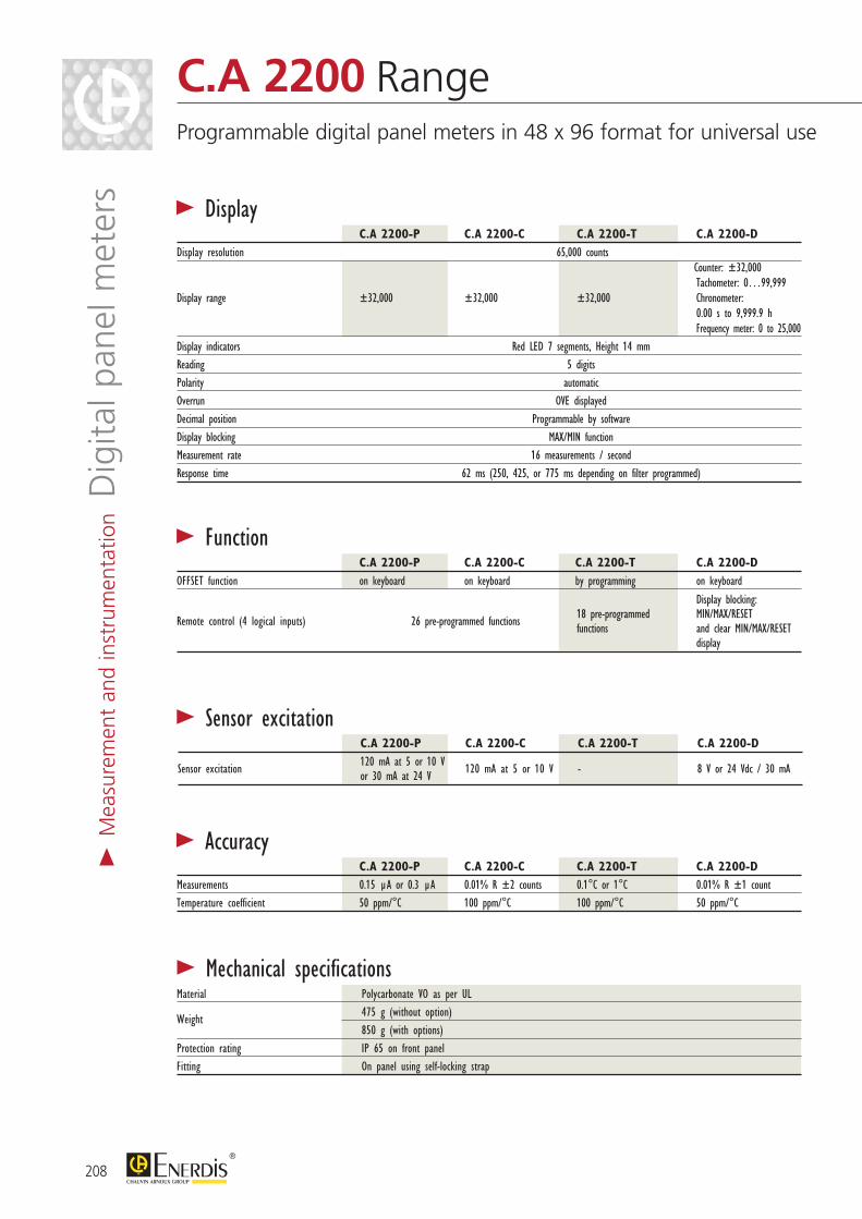
> Mechanical specificationsMaterial Polycarbonate VO as per UL
Weight 475 g (without option) 850 g (with options) Protection rating IP 65 on front panel Fitting On panel using self-locking strap
> Display C.A 2200-P C.A 2200-C C.A 2200-T C.A 2200-DDisplay resolution 65,000 counts Counter: ±32,000 Tachometer: 0…99,999Display range ±32,000 ±32,000 ±32,000 Chronometer: 0.00 s to 9,999.9 h Frequency meter: 0 to 25,000Display indicators Red LED 7 segments, Height 14 mm Reading 5 digits Polarity automatic Overrun OVE displayed Decimal position Programmable by software Display blocking MAX/MIN function Measurement rate 16 measurements / second Response time 62 ms (250, 425, or 775 ms depending on filter programmed)
> Sensor excitation C.A 2200-P C.A 2200-C C.A 2200-T C.A 2200-D
Sensor excitation 120 mA at 5 or 10 V 120 mA at 5 or 10 V - 8 V or 24 Vdc / 30 mA or 30 mA at 24 V
> Accuracy C.A 2200-P C.A 2200-C C.A 2200-T C.A 2200-DMeasurements 0.15 µA or 0.3 µA 0.01% R ±2 counts 0.1°C or 1°C 0.01% R ±1 countTemperature coefficient 50 ppm/°C 100 ppm/°C 100 ppm/°C 50 ppm/°C
> Function C.A 2200-P C.A 2200-C C.A 2200-T C.A 2200-DOFFSET function on keyboard on keyboard by programming on keyboard
Display blocking:
Remote control (4 logical inputs) 26 pre-programmed functions 18 pre-programmed MIN/MAX/RESET functions and clear MIN/MAX/RESET display
208
C.A 2200 RangeProgrammable digital panel meters in 48 x 96 format for universal use
> M
easu
rem
ent
and
inst
rum
enta
tion D
igita
l pan
el m
eter
s
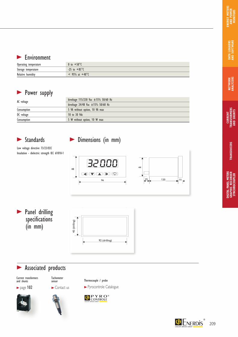
92 (drilling)
45 (
drill
ing)
92 (drilling)
45 (
drill
ing)
> Dimensions (in mm)
> Panel drilling specifications (in mm)
> EnvironmentOperating temperature 0 to +50°CStorage temperature -25 to +85°CRelative humidity < 95% at +40°C
> Power supplyAC voltage bivoltage 115/230 Vac ±15% 50/60 Hz bivoltage 24/48 Vac ±15% 50/60 Hz Consumption 5 VA without option, 10 VA max DC voltage 10 to 30 Vdc Consumption 5 W without option, 10 W max
> StandardsLow voltage directive 73/23/EECInsulation - dielectric strength IEC 61010-1
209
CURR
ENT
TRAN
SFOR
MER
SAN
D SH
UNTS
DIGI
TAL
PANE
L M
ETER
SGR
APHI
C RE
CORD
ERSY
NCHR
OCOU
PLER
NETW
ORK
ANAL
YZER
STR
ANSD
UCER
SDA
TA L
OGGE
RS
AND
SOFT
WAR
E
ENER
GY M
ETER
S AN
D PO
WER
M
ONIT
ORS
> Associated productsCurrent transformers and shunts
> page 102
Tachometer sensor
> Contact us
Thermocouple / probe
> Pyrocontrole Catalogue
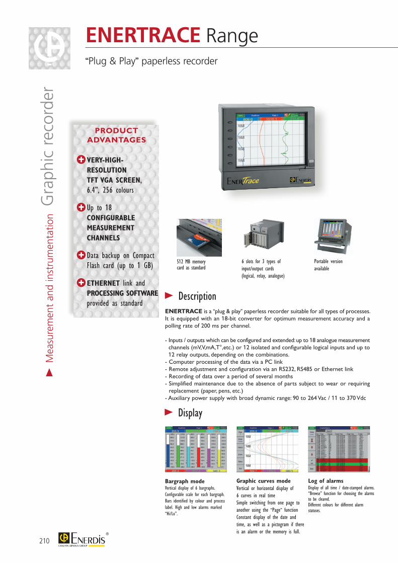
210
Bargraph mode Vertical display of 6 bargraphs.Configurable scale for each bargraph.Bars identified by colour and process label. High and low alarms marked “Hi/Lo”.
Graphic curves mode Vertical or horizontal display of 6 curves in real timeSimple switching from one page to another using the “Page” functionConstant display of the date and time, as well as a pictogram if there is an alarm or the memory is full.
Log of alarms Display of all time / date-stamped alarms. “Browse” function for choosing the alarms to be cleared.Different colours for different alarm statuses.
512 MB memorycard as standard
6 slots for 3 types of input/output cards (logical, relay, analogue)
Portable version available
> Description
> Display
ENERTRACE is a “plug & play” paperless recorder suitable for all types of processes. It is equipped with an 18-bit converter for optimum measurement accuracy and a polling rate of 200 ms per channel.
- Inputs / outputs which can be configured and extended: up to 18 analogue measurement channels (mV,V,mA,T°,etc.) or 12 isolated and configurable logical inputs and up to 12 relay outputs, depending on the combinations.
- Computer processing of the data via a PC link- Remote adjustment and configuration via an RS232, RS485 or Ethernet link- Recording of data over a period of several months- Simplified maintenance due to the absence of parts subject to wear or requiring
replacement (paper, pens, etc.)- Auxiliary power supply with broad dynamic range: 90 to 264 Vac / 11 to 370 Vdc
ENERTRACE Range“Plug & Play” paperless recorder
PRODUCT ADVANTAGES
VERY-HIGH-RESOLUTION TFT VGA SCREEN, 6.4”, 256 colours
Up to 18
CONFIGURABLE MEASUREMENT CHANNELS
Data backup on Compact Flash card (up to 1 GB)
ETHERNET link and PROCESSING SOFTWARE provided as standard
> M
easu
rem
ent
and
inst
rum
enta
tion G
raph
ic r
ecor
der
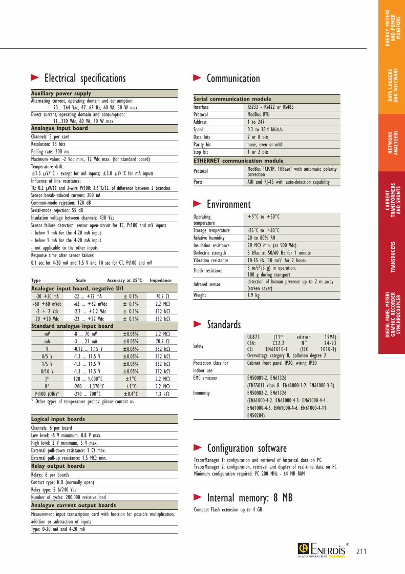
211
CURR
ENT
TRAN
SFOR
MER
SAN
D SH
UNTS
DIGI
TAL
PANE
L M
ETER
SGR
APHI
C RE
CORD
ERSY
NCHR
OCOU
PLER
NETW
ORK
ANAL
YZER
STR
ANSD
UCER
SDA
TA L
OGGE
RS
AND
SOFT
WAR
E
ENER
GY M
ETER
S AN
D PO
WER
M
ONIT
ORS
Auxiliary power supply Alternating current, operating domain and consumption: 90... 264 Vac, 47...63 Hz, 60 VA, 30 W max.Direct current, operating domain and consumption: 11...370 Vdc, 60 VA, 30 W max.Analogue input boardChannels: 3 per cardResolution: 18 bitsPolling rate: 200 msMaximum value: -2 Vdc min., 12 Vdc max. (for standard board)Temperature drift:±1.5 μV/°C - except for mA inputs; ±3.0 μV/°C for mA inputs Influence of line resistance: TC: 0.2 μV/Ω and 3-wire Pt100: 2.6°C/Ω. of difference between 2 branchesSensor break-induced current: 200 nA Common-mode rejection: 120 dB Serial-mode rejection: 55 dBInsulation voltage between channels: 430 VacSensor failure detection: sensor open-circuit for TC, Pt100 and mV inputs- below 1 mA for the 4-20 mA input- below 1 mA for the 4-20 mA input- not applicable to the other inputsResponse time after sensor failure:0.1 sec for 4-20 mA and 1.5 V and 10 sec for CT, Pt100 and mV
> Electrical specifications
> EnvironmentOperating +5°C to +50°C temperature Storage temperature -25°C to +60°CRelative humidity 20 to 80% RHInsulation resistance 20 MΩ min. (at 500 Vdc)Dielectric strength 3 kVac at 50/60 Hz for 1 minuteVibration resistance 10-55 Hz, 10 m/s2 for 2 hours
Shock resistance 3 m/s2 (3 g) in operation, 100 g during transport
Infrared sensor detection of human presence up to 2 m away (screen saver)Weight 1.9 kg
> Standards UL873 (11th edition 1994) CSA: C22.2 N° 24-93 Safety CE: EN61010-1 (IEC 1010-1) Overvoltage category II, pollution degree 2 Protection class for Cabinet front panel IP30, wiring IP20 indoor use EMC emission EN50081-2. EN61326 (EN55011 class B. EN61000-3-2. EN61000-3-3) Immunity EN50082-2. EN61326 (EN61000-4-2. EN61000-4-3. EN61000-4-4. EN61000-4-5. EN61000-4-6. EN61000-4-11. EN50204)
> Configuration software
> Internal memory: 8 MB
TracerManager 1: configuration and retrieval of historical data on PCTracerManager 2: configuration, retrieval and display of real-time data on PCMinimum configuration required: PC 200 MHz - 64 MB RAM
Compact Flash extension up to 4 GB
> Communication
Serial communication moduleInterface RS232 - RS422 or RS485 Protocol ModBus RTU Address 1 to 247Speed 0.3 to 38.4 kbits/sData bits 7 or 8 bitsParity bit none, even or oddStop bit 1 or 2 bits
ETHERNET communication module
Protocol ModBus TCP/IP, 10BaseT with automatic polarity correctionPorts AUI and RJ-45 with auto-detection capability
Logical input boardsChannels: 6 per boardLow level: -5 V minimum, 0.8 V max.High level: 2 V minimum, 5 V max.External pull-down resistance: 1 Ω max.External pull-up resistance: 1.5 MΩ min.Relay output boardsRelays: 6 per boardsContact type: N.O (normally open)Relay type: 5 A/240 VacNumber of cycles: 200,000 resistive loadAnalogue current output boardsMeasurement input transcription card with function for possible multiplication, addition or subtraction of inputsType: 0-20 mA and 4-20 mA
Type Scale Accuracy at 25°C Impedance
Analogue input board, negative U/I -20 +20 mA -22 ... +22 mA ± 0.1% 70.5 Ω -60 +60 mVdc -62 ... +62 mVdc ± 0.1% 2.2 MΩ -2 + 2 Vdc -2.2 ... +2.2 Vdc ± 0.1% 332 kΩ 20 +20 Vdc -22 ... +22 Vdc ± 0.1% 332 kΩStandard analogue input board mV -8 ... 70 mV ±0.05% 2.2 MΩ mA -3 ... 27 mA ±0.05% 70.5 Ω V -0.12 ... 1.15 V ±0.05% 332 kΩ 0/5 V -1.3 ... 11.5 V ±0.05% 332 kΩ 1/5 V -1.3 ... 11.5 V ±0.05% 332 kΩ 0/10 V -1.3 ... 11.5 V ±0.05% 332 kΩ J* 120 ... 1,000°C ±1°C 2.2 MΩ K* -200 ... 1,370°C ±1°C 2.2 MΩ Pt100 (DIN)* -210 ... 700°C ±0.4°C 1.3 kΩ* Other types of temperature probes: please contact us
212
wireswires
Load
Load
AC
B1
AC orCC
Load
> Electrical connections > Dimensions
> Panel cut-outs
Analogue inputs
Analogue inputs
Logical inputs
Relay outputs
Pt100, TC, mV, V, mA
Transducers
> page 152
> Associated productsCT Currenttransformers
> page 102
> M
easu
rem
ent
and
inst
rum
enta
tion G
raph
ic r
ecor
der
ENERTRACE Range“Plug & Play” paperless recorder
213
CURR
ENT
TRAN
SFOR
MER
SAN
D SH
UNTS
DIGI
TAL
PANE
L M
ETER
SGR
APHI
C RE
CORD
ERSY
NCHR
OCOU
PLER
NETW
ORK
ANAL
YZER
STR
ANSD
UCER
SDA
TA L
OGGE
RS
AND
SOFT
WAR
E
ENER
GY M
ETER
S AN
D PO
WER
M
ONIT
ORS
ENERTRACE
1 2 3 4 5 6 7 8 9 10 11 12
1 Power supply Code 4 90-264 Vac 47-63 Hz /110-370 Vdc standard 6 11-18 Vdc 7 18-36 Vdc 8 36-72 Vdc 2 Analogue inputs LR00112-000* 0 no analogue input 0 slot 3 3 analogue inputs 1 slot 6 6 analogue inputs 2 slots A 9 analogue inputs 3 slot B 12 analogue inputs 4 slots C 15 analogue inputs 5 slots D 18 analogue inputs 6 slots 3 Logical inputs LR00113-000* 0 no logical input 0 slot 1 6 logical inputs 1 slot 2 12 logical inputs 2 slots 4 Relay outputs LR00114-000* 0 no relay 0 slot 1 6 relays 1 slot 2 12 relays 2 slots 5 Communication 0 via Ethernet standard 1 RS232/422/485 (3 in 1) + Ethernet interface 6 Configuration software 1 “TracerManager1” standard 7 ENERTRACE software 0 basic version 1 calculation, counter and totalizer functions 8 Compact Flash 1 1 GB standard 9 ENERTRACE mounting 1 version for cabinet mounting standard 2 portable version with carrying handle
10 Option 0 no option 1 24 Vdc power supply for transmitters (6 max.) [1 slot] LR00115-000* 11 Analogue outputs LR00123-000* 0 no analogue output 0 slot 3 3 analogue mA outputs 1 slot 6 6 analogue mA outputs 2 slots A 9 analogue mA outputs 3 slots 12 Negative U/I analogue inputs LR00128-000* 0 no negative U/I input 0 slot 3 3 negative U/I inputs 1 slot 6 6 negative U/I inputs 2 slots A 9 negative U/I inputs 3 slots B 12 negative U/I inputs 4 slots C 15 negative U/I inputs 5 slots D 18 negative U/I inputs 6 slots
ACCESSORIES: “TracerManager2” software LR00132-000* 4 GB Compact Flash memory LR00121-000* Flash/USB adapter LR00127-000* *Can be sold separately
T O O R D E R
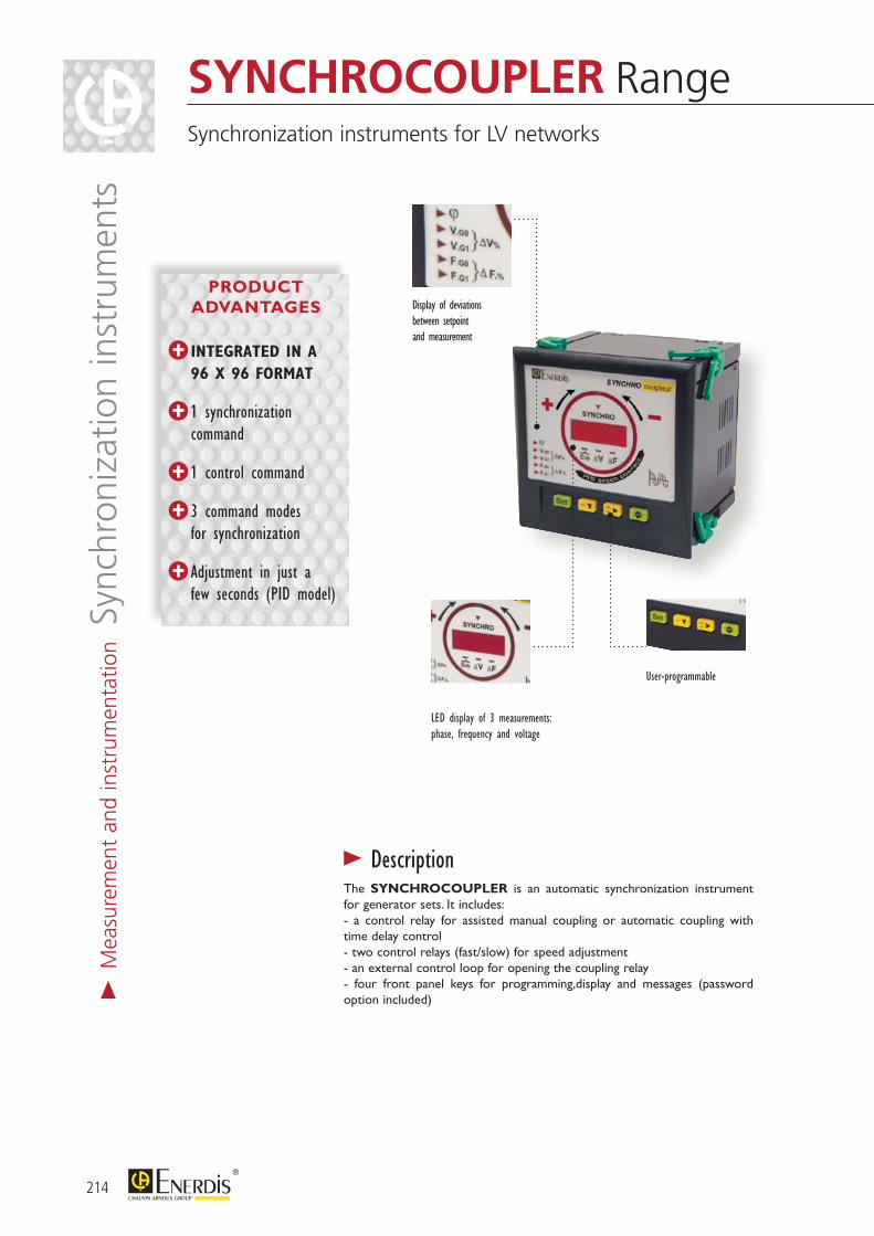
The SYNCHROCOUPLER is an automatic synchronization instrument for generator sets. It includes:- a control relay for assisted manual coupling or automatic coupling with time delay control- two control relays (fast/slow) for speed adjustment- an external control loop for opening the coupling relay- four front panel keys for programming,display and messages (password option included)
>Description
LED display of 3 measurements: phase, frequency and voltage
Display of deviations between setpoint and measurement
User-programmable
> M
easu
rem
ent
and
inst
rum
enta
tion S
ynch
roni
zatio
n in
stru
men
tsSYNCHROCOUPLER RangeSynchronization instruments for LV networks
INTEGRATED IN A 96 X 96 FORMAT
1 synchronization command
1 control command
3 command modes for synchronization
Adjustment in just a few seconds (PID model)
PRODUCT ADVANTAGES
214

215
CURR
ENT
TRAN
SFOR
MER
SAN
D SH
UNTS
DIGI
TAL
PANE
L M
ETER
SGR
APHI
C RE
CORD
ERSY
NCHR
OCOU
PLER
NETW
ORK
ANAL
YZER
STR
ANSD
UCER
SDA
TA L
OGGE
RS
AND
SOFT
WAR
E
ENER
GY M
ETER
S AN
D PO
WER
M
ONIT
ORS
SYNCHROCOUPLEUR
Display:
Phase angle variations by 30 LEDs arranged in a circle
Voltages, frequencies, variations (in %) on 4 digits
Frequency variations ±, status of coupler relay, conditions obtained in phase, frequency and voltage
Display: as for synchrocoupler
PID adjustment method (Proportional Integral Derivative) for synchronization that is faster and more accurate than with conventional synchronous couplers
Proportional: proportional correction of measurement errors
Integral: guarantees reduction of adjustment error to 0
Derivative: brings greater stability to the system, enabling you to anticipate the inertia of generator sets (e.g. hydroelectric)
SYNCHROCOUPLEUR PID
Power Supply Reference24 VDC LS9N 421X48 VDC LS9N 422X110 VAC LS9N 423X230 VAC LS9N 424X400 VAC LS9N 425X
Power Supply Reference24 VDC LS9N 441X48 VDC LS9N 442X110 VAC LS9N 443X230 VAC LS9N 444X400 VAC LS9N 445X
>Electrical specificationsMeasurementsRated voltage range 110 to 600 V
Frequency 35 Hz…80 Hz
Permanent overvoltage 800 V
Consumption < 500 µA
Relay output With sealed inverter contact 8 A - 250 Vac / 5 A - 30 Vdc
Multi-measurement (accuracy) Phase angle deviation ± 0.5°
Frequency ± 0.01 Hz
Voltage (RMS) Class 1 ± 2 digits
Auxiliary power supplyAC voltage -10% / +15%
Frequency 35 Hz…450 Hz
Consumption 10 VA
>EnvironmentOperating temperature -10°C to +65°C
Storage temperature -40°C to +70°C
Relative humidity < 90% at 40°C
Protection rating 3
Pollution level 2
Reference standardsSafety IEC 61010-1
Dimensions DIN 43700
EMC EN 61326-1
ANSI function Nos. 25 and 90
Resistance to shock IEC 60068-2-27
Resistance to vibrations IEC 60068-2-6
Environment IEC 60068-1
>Standards
>Mechanical specificationsCasing materialsCasing and flange Self-extinguishing black ABS
Front panel Light grey polycarbonate
Protection rating IP 54 front panel (IP 65 optional)
Weight 350 g
Connection Holder for 2.5 mm wire
Fitting Mounting on 8 mm front panel
SYNCHROCOUPLER RangeSynchronization instruments for LV networks
> M
easu
rem
ent
and
inst
rum
enta
tion S
ynch
roni
zatio
n in
stru
men
ts
216
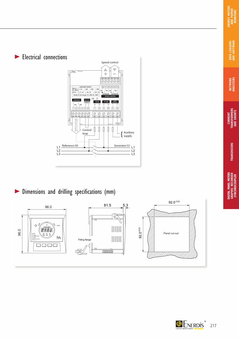
217
CURR
ENT
TRAN
SFOR
MER
SAN
D SH
UNTS
DIGI
TAL
PANE
L M
ETER
SGR
APHI
C RE
CORD
ERSY
NCHR
OCOU
PLER
NETW
ORK
ANAL
YZER
STR
ANSD
UCER
SDA
TA L
OGGE
RS
AND
SOFT
WAR
E
ENER
GY M
ETER
S AN
D PO
WER
M
ONIT
ORS
Speed control
Auxiliarysupply
Control loop
Reference G0 Generator G1
81.5 5.3
Fitting flange
92.0
+0,
8
92.0
96.0
96.0
+0,8
SYNCHRO
VEnb FVg1Vg0
F.G1F.G0
V%
F.%
Panel cut-out
81.5 5.3
Bride de fixation
92.0
+0,
8
92.0
96.0
96.0
+0,8
SYNCHRO
VEnb FVg1Vg0
F.G1F.G0
V%
F.%
Découpe du panneau
81.5 5.3
Fitting flange
92.0
+0,
8
92.0
96.0
96.0
+0,8
SYNCHRO
VEnb FVg1Vg0
F.G1F.G0
V%
F.%
Panel cut-out
>Electrical connections
>Dimensions and drilling specifications (mm)
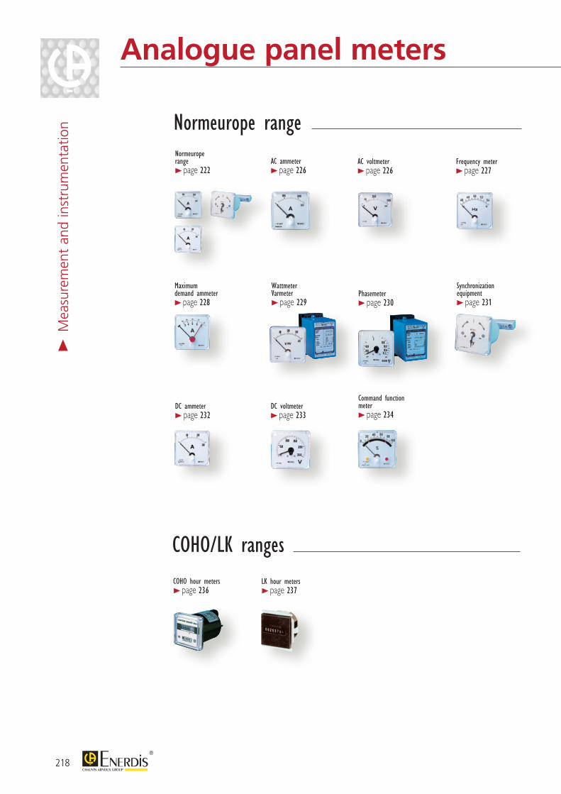
218
COHO/LK rangesCOHO hour meters > page 236
LK hour meters > page 237
Analogue panel meters>
Mea
sure
men
t an
d in
stru
men
tatio
n
Normeurope range > page 222
Synchronization equipment > page 231
DC ammeter > page 232
Maximum demand ammeter > page 228
Wattmeter Varmeter > page 229
Phasemeter > page 230
DC voltmeter > page 233
Command function meter > page 234
AC ammeter > page 226
Frequency meter > page 227
Normeurope range
AC voltmeter > page 226
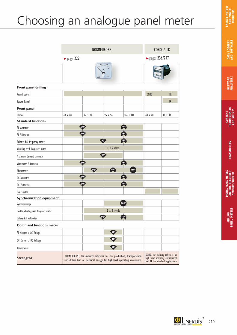
219
ANAL
OG
PANE
L M
ETER
S
CURR
ENT
TRAN
SFOR
MER
SAN
D SH
UNTS
DIGI
TAL
PANE
L M
ETER
SGR
APHI
C RE
CORD
ERSY
NCHR
OCOU
PLER
NETW
ORK
ANAL
YZER
STR
ANSD
UCER
SDA
TA L
OGGE
RS
AND
SOFT
WAR
E
ENER
GY M
ETER
S AN
D PO
WER
M
ONIT
ORS
Choosing an analogue panel meter
Front panel drilling
Round barrel
Square barrel
Front panel
Format 48 x 48 72 x 72 96 x 96 144 x 144 48 x 48 48 x 48
Standard functions
AC Ammeter
AC Voltmeter
Pointer dial frequency meter
Vibrating reed frequency meter
Maximum demand ammeter
Wattmeter / Varmeter
Phasemeter
DC Ammeter
DC Voltmeter
Hour meter
Synchronization equipment
Synchronoscope
Double vibrating reed frequency meter
Differential voltmeter
Command functions meter
AC Current / AC Voltage
DC Current / DC Voltage
Temperature
Strengths NORMEUROPE, the industry reference for the production, transportation and distribution of electrical energy for high-level operating constraints.
COHO, the industry reference for high limit operating environments and LK for standard applications.
NORMEUROPE
> page 222
COHO / LK
> pages 236/237
LK
COHO LK
2 x 9 reeds
80°90°
180°
250° 240°
360°
144°
60°54°105°
80°90°
180°
250° 240°
360°
144°
60°54°105°
80°90°
180°
250° 240°
360°
144°
60°54°105°
80°90°
180°
250° 240°
360°
144°
60°54°105°
80°90°
180°
250° 240°
360°
144°
60°54°105°
80°90°
180°
250° 240°
360°
144°
60°54°105°
1 x 9 reeds
80°90°
180°
250° 240°
360°
144°
60°54°105°
80°90°
180°
250° 240°
360°
144°
60°54°105°
80°90°
180°
250° 240°
360°
144°
60°54°105°
80°90°
180°
250° 240°
360°
144°
60°54°105°
80°90°
180°
250° 240°
360°
144°
60°54°105°
80°90°
180°
250° 240°
360°
144°
60°54°105°
80°90°
180°
250° 240°
360°
144°
60°54°105°
80°90°
180°
250° 240°
360°
144°
60°54°105°
80°90°
180°
250° 240°
360°
144°
60°54°105°
80°90°
180°
250° 240°
360°
144°
60°54°105°
80°90°
180°
250° 240°
360°
144°
60°54°105°
80°90°
180°
250° 240°
360°
144°
60°54°105°
80°90°
180°
250° 240°
360°
144°
60°54°105°80°90°
180°
250° 240°
360°
144°
60°54°105°
80°90°
180°
250° 240°
360°
144°
60°54°105°
80°90°
180°
250° 240°
360°
144°
60°54°105°

Info & advice
MOVING IRON OR MOVING COIL?The electric current is read directly by a sensor guiding the pointer movement. The two most usual types are:
Moving iron
Ms
C
The moving iron panel meter is composed of a fixed magnet and a mobile magnet, mutually repel-lent and placed in the field of a
coil powered by the current to be mea-sured. The moving iron panel meter carries out measurements in true RMS.Calibrated for alternating current, it can also measure values in direct current but with a diminished accuracy rating of about 3. The scale can be normal, motor or expanded.
Moving coil
M s
C
The moving coil panel meter is composed of a coil traversed by the current to be measured which pivots around a permanently fixed
magnet. Due to its low consumption, the moving coil panel meter is the ideal instrument for the measurement of low direct current values. Its scale is linear.
> M
easu
rem
ent
and
inst
rum
enta
tion
Ana
logu
e pa
nel m
eter
s
The essential function of the analogue panel meteris to display instantaneousand variable values. It shows the pointer’s position andmovement, both requiredfor monitoring industrialprocesses.
SELECTING A PANEL METER As a panel meter is a low-cost item, it is easily installed at the various command and monitoring points: the switchboard panels of LV distribution networks, motor drive control units or automation device panels.
FunctionsChoose the quantity to be displayed in order to monitor and control a known risk. For an electrical line, for example, the voltage is selected as it is crucial for ensuring user safety.
ErgonomicsChoose the instrument size depending on the distance between the operator and the mounting panel. Choose the pointer deflection: a deflection of 240°may be preferred to the usual 90°deflection, to facilitate the reading of extended ranges.
Environmental constraints and standardsIt is important to take into account mechanical specifications, environmental restrictions, standards in force, consumption and compatibility with sensors, in order to choose the appropriate dial ranges and calibration scales.
Options and accessoriesPanel meters, though robust by nature, are never-theless sensitive to degraded environments. It is therefore recommended to choose customized solutions for military applications, for onboard rail applications or for explosive atmospheres.
220
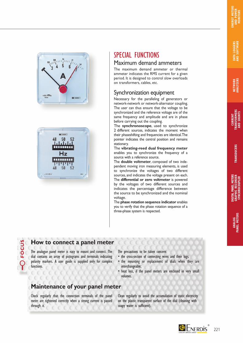
SPECIAL FUNCTIONSMaximum demand ammetersThe maximum demand ammeter or thermal ammeter indicates the RMS current for a given period. It is designed to control slow overloads on transformers, cables, etc.
Synchronization equipmentNecessary for the paralleling of generators or network-network or network-alternator coupling. The user can thus ensure that the voltage to be synchronized and the reference voltage are of the same frequency and amplitude and are in phase before carrying out the coupling.The synchronoscope, used to synchronize 2 different sources, indicates the moment when their phaseshifting and frequencies are identical. The pointer indicates the central position and remains stationary. The vibrating-reed dual frequency meter enables you to synchronize the frequency of a source with a reference source. The double voltmeter, composed of two inde-pendent moving iron measuring elements, is used to synchronize the voltages of two different sources, and indicates the voltage present on each.The differential or zero voltmeter is powered by the voltages of two different sources and indicates the percentage difference between the source to be synchronized and the nominal voltage.The phase rotation sequence indicator enables you to verify that the phase rotation sequence of a three-phase system is respected.
FO
CU
S
The analogue panel meter is easy to mount and connect. The dial contains an array of pictograms and terminals indicating polarity markers. A user guide is supplied only for complex functions.
The precautions to be taken concern:• the cross-section of connecting wires and their lugs;• the mounting or replacement of dials when they are
interchangeable;• heat loss, if the panel meters are enclosed in very small
volumes.
How to connect a panel meter
Check regularly that the connection terminals of the panel meter are tightened correctly when a strong current is passed through it.
Clean regularly to avoid the accumulation of static electricity on the plastic transparent surface of the dial (cleaning with soapy water is sufficient).
Maintenance of your panel meter
221
ANAL
OG
PANE
L M
ETER
S
CURR
ENT
TRAN
SFOR
MER
SAN
D SH
UNTS
DIGI
TAL
PANE
L M
ETER
SGR
APHI
C RE
CORD
ERSY
NCHR
OCOU
PLER
NETW
ORK
ANAL
YZER
STR
ANSD
UCER
SDA
TA L
OGGE
RS
AND
SOFT
WAR
E
ENER
GY M
ETER
S AN
D PO
WER
M
ONIT
ORS

> M
easu
rem
ent
and
inst
rum
enta
tion
Ana
logu
e pa
nel m
eter
s
Accurate Slim-line, small barrel diameter, multiple connection possibilities
Attractive design and easy to read
Standard: IEC 60051-1 Accuracy: class 1.5 (± 1.5% error margin at full scale) Front panel protection: IEC 60529 (see presentation table) Insulation test: IEC 61010-1 Category III Maximum service voltage: 650 Vac Mechanical shock resistance: IEC 68-2-27 Vibration resistance: IEC 60068-2-6 Environment: IEC 68-1 Reference temperature: 23°C ± 2°C Operating temperature: -25°C to +50°C Storage temperature: -25°C to +70°C Relative humidity: < 90% at 40°C Mounting: • Front panel mounting • Panel thickness: 8 mm max.
Materials: Barrel: self-extinguishing polycarbonate Front panel: polymethyl methacrylate (glass option NEL) Additional terminal: socket in Bakelite, cover in ABS Dial: light alloy, black markers on white background Black knife-edge arrow pointer Operating position: calibrated for vertical position (± 10%) Overloads: Voltmeter and frequency meter - 1.2 Un permanent - 2 Un during 5 secs Ammeter - 1.3 In permanent - 10 In during 5 secs Extreme values: Safety recommendation IEC 60 051-1 1-1.2 - 1.5 - 2 - 2.5 - 3 - 4 - 5 - 6 - 7.5 - 8 - 9 and their multiples and decimal sub-multiples
> General specifications
222
NORMEUROPE RangeRound barrel analogue panel meters for high-level operating constraints
PRODUCT ADVANTAGES
WIDE CLIENT REFERENCE BASE: main utilities, marine applications, energy producers and distributors
WIDE CHOICE
of functions, formats, ratings and options
LONG PRODUCT LIFE SPAN
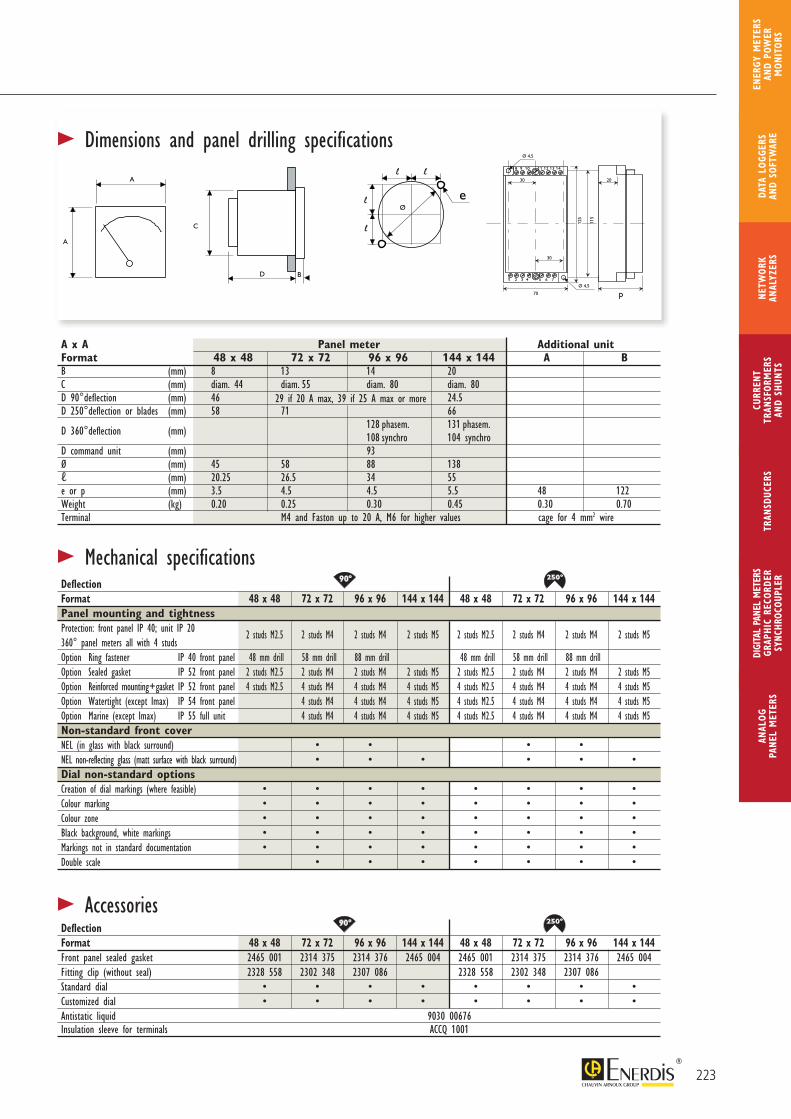
80°90°
180°
250° 240°
360°
144°
60°54°105°
80°90°
180°
250° 240°
360°
144°
60°54°105°
80°90°
180°
250° 240°
360°
144°
60°54°105°
80°90°
180°
250° 240°
360°
144°
60°54°105°
A
A C
Dl l
l
l
eØ
2030
30
p
1 2 3 4 5 6 7
8 9 10 11 12 13 14
70
125
115
Ø 4,5
Ø 4,5
BA
A C
Dl l
l
l
eØ
2030
30
p
1 2 3 4 5 6 7
8 9 10 11 12 13 14
70
125
115
Ø 4,5
Ø 4,5
B
A
A C
Dl l
l
l
eØ
2030
30
p
1 2 3 4 5 6 7
8 9 10 11 12 13 14
70
125
115
Ø 4,5
Ø 4,5
B
A
A C
Dl l
l
l
eØ
2030
30
p
1 2 3 4 5 6 7
8 9 10 11 12 13 14
70
125
115
Ø 4,5
Ø 4,5
B
> Dimensions and panel drilling specifications
> Mechanical specifications
> AccessoriesDeflectionFormat 48 x 48 72 x 72 96 x 96 144 x 144 48 x 48 72 x 72 96 x 96 144 x 144Front panel sealed gasket 2465 001 2314 375 2314 376 2465 004 2465 001 2314 375 2314 376 2465 004Fitting clip (without seal) 2328 558 2302 348 2307 086 2328 558 2302 348 2307 086 Standard dial • • • • • • • •Customized dial • • • • • • • •Antistatic liquid 9030 00676Insulation sleeve for terminals ACCQ 1001
DeflectionFormat 48 x 48 72 x 72 96 x 96 144 x 144 48 x 48 72 x 72 96 x 96 144 x 144Panel mounting and tightnessProtection: front panel IP 40; unit IP 20 2 studs M2.5 2 studs M4 2 studs M4 2 studs M5 2 studs M2.5 2 studs M4 2 studs M4 2 studs M5360° panel meters all with 4 studsOption Ring fastener IP 40 front panel 48 mm drill 58 mm drill 88 mm drill 48 mm drill 58 mm drill 88 mm drillOption Sealed gasket IP 52 front panel 2 studs M2.5 2 studs M4 2 studs M4 2 studs M5 2 studs M2.5 2 studs M4 2 studs M4 2 studs M5Option Reinforced mounting+gasket IP 52 front panel 4 studs M2.5 4 studs M4 4 studs M4 4 studs M5 4 studs M2.5 4 studs M4 4 studs M4 4 studs M5Option Watertight (except Imax) IP 54 front panel 4 studs M4 4 studs M4 4 studs M5 4 studs M2.5 4 studs M4 4 studs M4 4 studs M5Option Marine (except Imax) IP 55 full unit 4 studs M4 4 studs M4 4 studs M5 4 studs M2.5 4 studs M4 4 studs M4 4 studs M5Non-standard front coverNEL (in glass with black surround) • • • •NEL non-reflecting glass (matt surface with black surround) • • • • • •Dial non-standard optionsCreation of dial markings (where feasible) • • • • • • • •Colour marking • • • • • • • •Colour zone • • • • • • • •Black background, white markings • • • • • • • •Markings not in standard documentation • • • • • • • •Double scale • • • • • • •
A x A Panel meter Additional unitFormat 48 x 48 72 x 72 96 x 96 144 x 144 A BB (mm) 8 13 14 20C (mm) diam. 44 diam. 55 diam. 80 diam. 80D 90°deflection (mm) 46 24.5D 250°deflection or blades (mm) 58 71 66
D 360°deflection (mm) 128 phasem. 131 phasem. 108 synchro 104 synchroD command unit (mm) 93Ø (mm) 45 58 88 138ℓ (mm) 20.25 26.5 34 55e or p (mm) 3.5 4.5 4.5 5.5 48 122Weight (kg) 0.20 0.25 0.30 0.45 0.30 0.70Terminal M4 and Faston up to 20 A, M6 for higher values cage for 4 mm2 wire
29 if 20 A max, 39 if 25 A max or more
223
ANAL
OG
PANE
L M
ETER
S
CURR
ENT
TRAN
SFOR
MER
SAN
D SH
UNTS
DIGI
TAL
PANE
L M
ETER
SGR
APHI
C RE
CORD
ERSY
NCHR
OCOU
PLER
NETW
ORK
ANAL
YZER
STR
ANSD
UCER
SDA
TA L
OGGE
RS
AND
SOFT
WAR
E
ENER
GY M
ETER
S AN
D PO
WER
M
ONIT
ORS
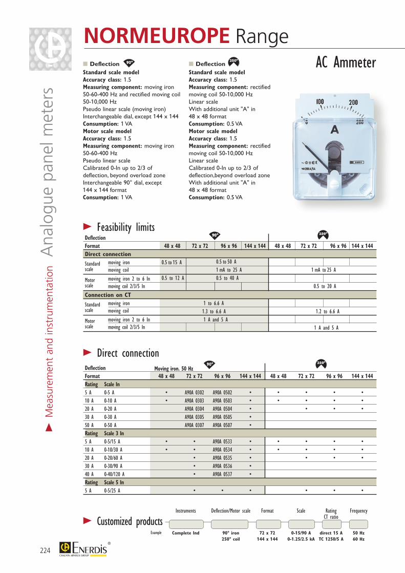
80°90°
180°
250° 240°
360°
144°
60°54°105°
80°90°
180°
250° 240°
360°
144°
60°54°105°
80°90°
180°
250° 240°
360°
144°
60°54°105°
80°90°
180°
250° 240°
360°
144°
60°54°105°
80°90°
180°
250° 240°
360°
144°
60°54°105°
80°90°
180°
250° 240°
360°
144°
60°54°105°
DeflectionStandard scale model Accuracy class: 1.5 Measuring component: moving iron 50-60-400 Hz and rectified moving coil 50-10,000 Hz Pseudo linear scale (moving iron) Interchangeable dial, except 144 x 144 Consumption: 1 VA Motor scale model Accuracy class: 1.5 Measuring component: moving iron 50-60-400 Hz Pseudo linear scale Calibrated 0-In up to 2/3 of deflection, beyond overload zone Interchangeable 90° dial, except 144 x 144 format Consumption: 1 VA
Deflection Standard scale model Accuracy class: 1.5 Measuring component: rectified moving coil 50-10,000 Hz Linear scale With additional unit "A" in 48 x 48 format Consumption: 0.5 VA Motor scale model Accuracy class: 1.5 Measuring component: rectified moving coil 50-10,000 Hz Linear scale Calibrated 0-In up to 2/3 of deflection,beyond overload zone With additional unit "A" in 48 x 48 format Consumption: 0.5 VA
> Customized products
AC Ammeter
> Direct connection
> Feasibility limits Deflection Format 48 x 48 72 x 72 96 x 96 144 x 144 48 x 48 72 x 72 96 x 96 144 x 144Direct connection
Standard moving iron 0.5 to 15 A 0.5 to 50 A scale moving coil 1 mA to 25 A 1 mA to 25 A
Motor moving iron 2 to 6 In 0.5 to 12 A 0.5 to 40 A scale moving coil 2/3/5 In 0.5 to 20 A
Connection on CT
Standard moving iron 1 to 6.6 A scale moving coil 1.3 to 6.6 A 1.2 to 6.6 A
Motor moving iron 2 to 6 In 1 A and 5 A scale moving coil 2/3/5 In 1 A and 5 A
Deflection Moving iron. 50 Hz Format 48 x 48 72 x 72 96 x 96 144 x 144 48 x 48 72 x 72 96 x 96 144 x 144Rating Scale In 5 A 0-5 A • A90A 0302 A90A 0502 • • • • •10 A 0-10 A • A90A 0303 A90A 0503 • • • • •20 A 0-20 A A90A 0304 A90A 0504 • • • •30 A 0-30 A A90A 0305 A90A 0505 • 50 A 0-50 A A90A 0307 A90A 0507 • Rating Scale 3 In 5 A 0-5/15 A • • A90A 0533 • • • • •10 A 0-10/30 A • • A90A 0534 • • • • •20 A 0-20/60 A • A90A 0535 • • • •30 A 0-30/90 A • A90A 0536 • 40 A 0-40/120 A • A90A 0537 • Rating Scale 5 In 5 A 0-5/25 A • • • • • •
Instruments Deflection/Motor scale Format Scale Rating Frequency CT ratio
Complete Ind 90° iron 72 x 72 0-15/90 A direct 15 A 50 Hz 250° coil 144 x 144 0-1.25/2.5 kA TC 1250/5 A 60 Hz
Example
224
NORMEUROPE Range>
Mea
sure
men
t an
d in
stru
men
tatio
n A
nalo
gue
pane
l met
ers
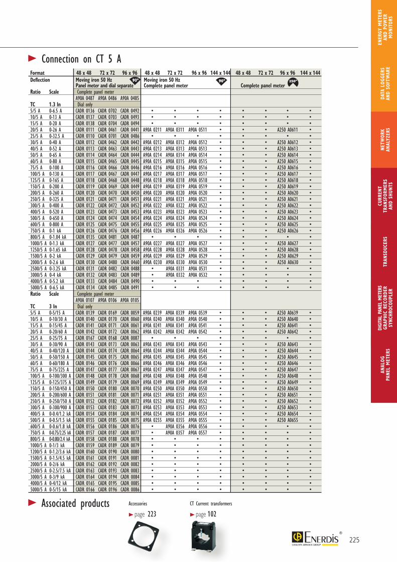
80°90°
180°
250° 240°
360°
144°
60°54°105° 80°90°
180°
250° 240°
360°
144°
60°54°105°
80°90°
180°
250° 240°
360°
144°
60°54°105°
Format 48 x 48 72 x 72 96 x 96 48 x 48 72 x 72 96 x 96 144 x 144 48 x 48 72 x 72 96 x 96 144 x 144Deflection Moving iron 50 Hz Moving iron 50 Hz Panel meter and dial separate Complete panel meter Complete panel meter Ratio Scale Complete panel meter A90A 0487 A90A 0486 A90A 0485TC 1.3 In Dial only 5/5 A 0-6.5 A CADR 0136 CADR 0702 CADR 0492 • • • • • • • •10/5 A 0-13 A CADR 0137 CADR 0703 CADR 0493 • • • • • • • •15/5 A 0-20 A CADR 0138 CADR 0704 CADR 0494 • • • • • • • •20/5 A 0-26 A CADR 0111 CADR 0461 CADR 0441 A90A 0211 A90A 0311 A90A 0511 • • • A250 A0611 •25/5 A 0-32.5 A CADR 0110 CADR 0701 CADR 0486 • • • • • • • •30/5 A 0-40 A CADR 0112 CADR 0462 CADR 0442 A90A 0212 A90A 0312 A90A 0512 • • • A250 A0612 •40/5 A 0-52 A CADR 0113 CADR 0463 CADR 0443 A90A 0213 A90A 0313 A90A 0513 • • • A250 A0613 •50/5 A 0-65 A CADR 0114 CADR 0464 CADR 0444 A90A 0214 A90A 0314 A90A 0514 • • • A250 A0614 •60/5 A 0-80 A CADR 0115 CADR 0465 CADR 0445 A90A 0215 A90A 0315 A90A 0515 • • • A250 A0615 •75/5 A 0-100 A CADR 0116 CADR 0466 CADR 0446 A90A 0216 A90A 0316 A90A 0516 • • • A250 A0616 •100/5 A 0-130 A CADR 0117 CADR 0467 CADR 0447 A90A 0217 A90A 0317 A90A 0517 • • • A250 A0617 •125/5 A 0-165 A CADR 0118 CADR 0468 CADR 0448 A90A 0218 A90A 0318 A90A 0518 • • • A250 A0618 •150/5 A 0-200 A CADR 0119 CADR 0469 CADR 0449 A90A 0219 A90A 0319 A90A 0519 • • • A250 A0619 •200/5 A 0-260 A CADR 0120 CADR 0470 CADR 0450 A90A 0220 A90A 0320 A90A 0520 • • • A250 A0620 •250/5 A 0-325 A CADR 0121 CADR 0471 CADR 0451 A90A 0221 A90A 0321 A90A 0521 • • • A250 A0621 •300/5 A 0-400 A CADR 0122 CADR 0472 CADR 0452 A90A 0222 A90A 0322 A90A 0522 • • • A250 A0622 •400/5 A 0-520 A CADR 0123 CADR 0473 CADR 0453 A90A 0223 A90A 0323 A90A 0523 • • • A250 A0623 •500/5 A 0-650 A CADR 0124 CADR 0474 CADR 0454 A90A 0224 A90A 0324 A90A 0524 • • • A250 A0624 •600/5 A 0-800 A CADR 0125 CADR 0475 CADR 0455 A90A 0225 A90A 0325 A90A 0525 • • • A250 A0625 •750/5 A 0-1 kA CADR 0126 CADR 0476 CADR 0456 A90A 0226 A90A 0326 A90A 0526 • • • A250 A0626 •800/5 A 0-1.04 kA CADR 0135 CADR 0481 CADR 0487 • • • • • • • •1000/5 A 0-1.3 kA CADR 0127 CADR 0477 CADR 0457 A90A 0227 A90A 0327 A90A 0527 • • • A250 A0627 •1250/5 A 0-1.65 kA CADR 0128 CADR 0478 CADR 0458 A90A 0228 A90A 0328 A90A 0528 • • • A250 A0628 •1500/5 A 0-2 kA CADR 0129 CADR 0479 CADR 0459 A90A 0229 A90A 0329 A90A 0529 • • • A250 A0629 •2000/5 A 0-2.6 kA CADR 0130 CADR 0480 CADR 0460 A90A 0230 A90A 0330 A90A 0530 • • • A250 A0630 •2500/5 A 0-3.25 kA CADR 0131 CADR 0482 CADR 0488 • A90A 0331 A90A 0531 • • • • •3000/5 A 0-4 kA CADR 0132 CADR 0483 CADR 0489 • A90A 0332 A90A 0532 • • • • •4000/5 A 0-5.2 kA CADR 0133 CADR 0484 CADR 0490 • • • • • • • •5000/5 A 0-6.5 kA CADR 0134 CADR 0485 CADR 0491 • • • • • • • •Ratio Scale Complete panel meter A90A 0107 A90A 0106 A90A 0105TC 3 In Dial only5/5 A 0-5/15 A CADR 0139 CADR 0169 CADR 0059 A90A 0239 A90A 0339 A90A 0539 • • • A250 A0639 •10/5 A 0-10/30 A CADR 0140 CADR 0170 CADR 0060 A90A 0240 A90A 0340 A90A 0540 • • • A250 A0640 •15/5 A 0-15/45 A CADR 0141 CADR 0171 CADR 0061 A90A 0241 A90A 0341 A90A 0541 • • • A250 A0641 •20/5 A 0-20/60 A CADR 0142 CADR 0172 CADR 0062 A90A 0242 A90A 0342 A90A 0542 • • • A250 A0642 •25/5 A 0-25/75 A CADR 0167 CADR 0168 CADR 0087 • • • • • • • •30/5 A 0-30/90 A CADR 0143 CADR 0173 CADR 0063 A90A 0243 A90A 0343 A90A 0543 • • • A250 A0643 •40/5 A 0-40/120 A CADR 0144 CADR 0174 CADR 0064 A90A 0244 A90A 0344 A90A 0544 • • • A250 A0644 •50/5 A 0-50/150 A CADR 0145 CADR 0175 CADR 0065 A90A 0245 A90A 0345 A90A 0545 • • • A250 A0645 •60/5 A 0-60/180 A CADR 0146 CADR 0176 CADR 0066 A90A 0246 A90A 0346 A90A 0546 • • • A250 A0646 •75/5 A 0-75/225 A CADR 0147 CADR 0177 CADR 0067 A90A 0247 A90A 0347 A90A 0547 • • • A250 A0647 •100/5 A 0-100/300 A CADR 0148 CADR 0178 CADR 0068 A90A 0248 A90A 0348 A90A 0548 • • • A250 A0648 •125/5 A 0-125/375 A CADR 0149 CADR 0179 CADR 0069 A90A 0249 A90A 0349 A90A 0549 • • • A250 A0649 •150/5 A 0-150/450 A CADR 0150 CADR 0180 CADR 0070 A90A 0250 A90A 0350 A90A 0550 • • • A250 A0650 •200/5 A 0-200/600 A CADR 0151 CADR 0181 CADR 0071 A90A 0251 A90A 0351 A90A 0551 • • • A250 A0651 •250/5 A 0-250/750 A CADR 0152 CADR 0182 CADR 0072 A90A 0252 A90A 0352 A90A 0552 • • • A250 A0652 •300/5 A 0-300/900 A CADR 0153 CADR 0183 CADR 0073 A90A 0253 A90A 0353 A90A 0553 • • • A250 A0653 •400/5 A 0-0.4/1.2 kA CADR 0154 CADR 0184 CADR 0074 A90A 0254 A90A 0354 A90A 0554 • • • A250 A0654 •500/5 A 0-0.5/1.5 kA CADR 0155 CADR 0185 CADR 0075 A90A 0255 A90A 0355 A90A 0555 • • • A250 A0655 •600/5 A 0-0.6/1.8 kA CADR 0156 CADR 0186 CADR 0076 • A90A 0356 A90A 0556 • • • • •750/5 A 0-0.75/2.25 kA CADR 0157 CADR 0187 CADR 0077 • A90A 0357 A90A 0557 • • • • •800/5 A 0-0.80/2.4 kA CADR 0158 CADR 0188 CADR 0078 • • • • • • • •1000/5 A 0-1/3 kA CADR 0159 CADR 0189 CADR 0079 • • • • • • • •1200/5 A 0-1.2/3.6 kA CADR 0160 CADR 0190 CADR 0080 • • • • • • • •1500/5 A 0-1.5/4.5 kA CADR 0161 CADR 0191 CADR 0081 • • • • • • • •2000/5 A 0-2/6 kA CADR 0162 CADR 0192 CADR 0082 • • • • • • • •2500/5 A 0-2.5/7.5 kA CADR 0163 CADR 0193 CADR 0083 • • • • • • • •3000/5 A 0-3/9 kA CADR 0164 CADR 0194 CADR 0084 • • • • • • • •4000/5 A 0-4/12 kA CADR 0165 CADR 0195 CADR 0085 • • • • • • • •5000/5 A 0-5/15 kA CADR 0166 CADR 0196 CADR 0086 • • • • • • • •
> Connection on CT 5 A
225
ANAL
OG
PANE
L M
ETER
S
CURR
ENT
TRAN
SFOR
MER
SAN
D SH
UNTS
DIGI
TAL
PANE
L M
ETER
SGR
APHI
C RE
CORD
ERSY
NCHR
OCOU
PLER
NETW
ORK
ANAL
YZER
STR
ANSD
UCER
SDA
TA L
OGGE
RS
AND
SOFT
WAR
E
ENER
GY M
ETER
S AN
D PO
WER
M
ONIT
ORS
> Associated products Accessories
> page 223CT Current transformers
> page 102
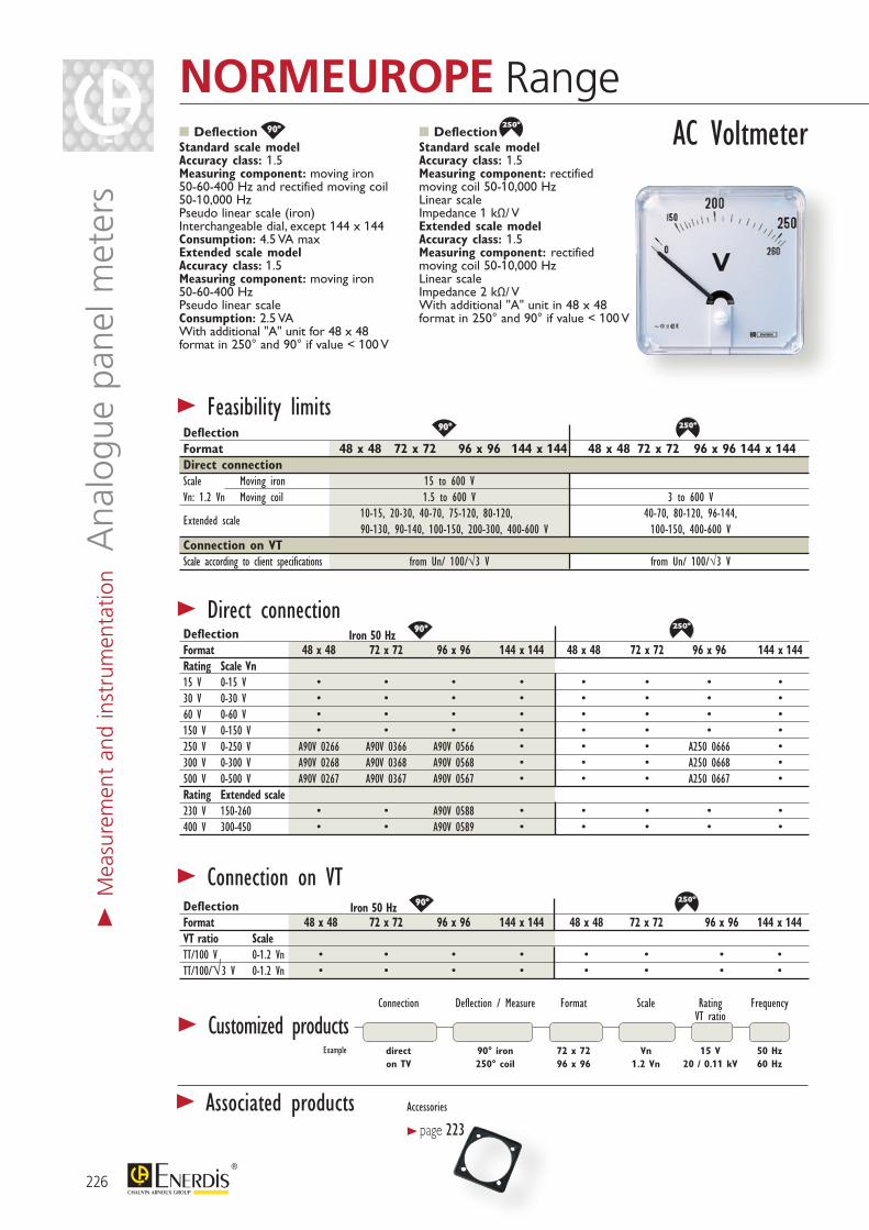
> Customized products Connection Deflection / Measure Format Scale Rating Frequency VT ratio
direct 90° iron 72 x 72 Vn 15 V 50 Hz on TV 250° coil 96 x 96 1.2 Vn 20 / 0.11 kV 60 Hz
Example
80°90°
180°
250° 240°
360°
144°
60°54°105°
80°90°
180°
250° 240°
360°
144°
60°54°105°
80°90°
180°
250° 240°
360°
144°
60°54°105°
80°90°
180°
250° 240°
360°
144°
60°54°105°
80°90°
180°
250° 240°
360°
144°
60°54°105°
80°90°
180°
250° 240°
360°
144°
60°54°105°
80°90°
180°
250° 240°
360°
144°
60°54°105°
80°90°
180°
250° 240°
360°
144°
60°54°105°
Deflection Standard scale model Accuracy class: 1.5 Measuring component: moving iron 50-60-400 Hz and rectified moving coil 50-10,000 Hz Pseudo linear scale (iron) Interchangeable dial, except 144 x 144 Consumption: 4.5 VA max Extended scale model Accuracy class: 1.5 Measuring component: moving iron 50-60-400 Hz Pseudo linear scale Consumption: 2.5 VA With additional "A" unit for 48 x 48 format in 250° and 90° if value < 100 V
Deflection Standard scale model Accuracy class: 1.5 Measuring component: rectified moving coil 50-10,000 Hz Linear scale Impedance 1 kΩ/ V Extended scale model Accuracy class: 1.5 Measuring component: rectified moving coil 50-10,000 Hz Linear scale Impedance 2 kΩ/ V With additional "A" unit in 48 x 48 format in 250° and 90° if value < 100 V
Deflection Iron 50 Hz Format 48 x 48 72 x 72 96 x 96 144 x 144 48 x 48 72 x 72 96 x 96 144 x 144Rating Scale Vn 15 V 0-15 V • • • • • • • •30 V 0-30 V • • • • • • • •60 V 0-60 V • • • • • • • •150 V 0-150 V • • • • • • • •250 V 0-250 V A90V 0266 A90V 0366 A90V 0566 • • • A250 0666 •300 V 0-300 V A90V 0268 A90V 0368 A90V 0568 • • • A250 0668 •500 V 0-500 V A90V 0267 A90V 0367 A90V 0567 • • • A250 0667 •Rating Extended scale 230 V 150-260 • • A90V 0588 • • • • •400 V 300-450 • • A90V 0589 • • • • •
Deflection Iron 50 Hz Format 48 x 48 72 x 72 96 x 96 144 x 144 48 x 48 72 x 72 96 x 96 144 x 144VT ratio Scale TT/100 V 0-1.2 Vn • • • • • • • •TT/100/√3 V 0-1.2 Vn • • • • • • • •
> Direct connection
> Connection on VT
> Feasibility limits
AC Voltmeter
Deflection Format 48 x 48 72 x 72 96 x 96 144 x 144 48 x 48 72 x 72 96 x 96 144 x 144Direct connectionScale Moving iron 15 to 600 V Vn: 1.2 Vn Moving coil 1.5 to 600 V 3 to 600 V
Extended scale 10-15, 20-30, 40-70, 75-120, 80-120, 40-70, 80-120, 96-144, 90-130, 90-140, 100-150, 200-300, 400-600 V 100-150, 400-600 VConnection on VTScale according to client specifications from Un/ 100/√3 V from Un/ 100/√3 V
226
NORMEUROPE Range
> Associated products
> M
easu
rem
ent
and
inst
rum
enta
tion
Ana
logu
e pa
nel m
eter
s
Accessories
> page 223
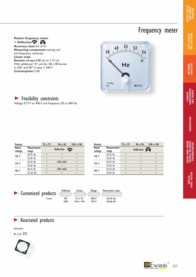
80°90°
180°
250° 240°
360°
144°
60°54°105°
80°90°
180°
250° 240°
360°
144°
60°54°105°
80°90°
180°
250° 240°
360°
144°
60°54°105°
80°90°
180°
250° 240°
360°
144°
60°54°105°
Example
Pointer frequency meter Deflection Accuracy class: 0.5 of Fn Measuring component: moving coil and frequency converter Linear scale Domain of use: 0.80 Un to 1.15 Un With additional "A" unit for 48 x 48 format in 250° and 90° if value < 100 V Consumption: 3 VA
> Feasibility constraintsVoltage 57.7 V to 440 V and frequency 50 to 400 Hz
Deflection Format Voltage Measurement range
90° 72 x 72 100 V 45-55 Hz 250° 144 x 144 110 V 45-65 Hz
Format 72 x 72 96 x 96 144 x 144Rated Measurement voltage range
100 V 45-55 Hz • • • 55-65 Hz • • •
230 V 45-55 Hz • FA90 0681 • 55-65 Hz • • •
400 V 45-55 Hz • FA90 0682 • 55-.65 Hz • • •
Frequency meter
> Customized products
Format 72 x 72 96 x 96 144 x 144Rated Measurement voltage range
100 V 45-55 Hz • • • 55-65 Hz • • •
230 V 45-55 Hz • • • 55-65 Hz • • •
400 V 45-55 Hz • • • 55-65 Hz • • •
DeflectionDeflection
227
ANAL
OG
PANE
L M
ETER
S
CURR
ENT
TRAN
SFOR
MER
SAN
D SH
UNTS
DIGI
TAL
PANE
L M
ETER
SGR
APHI
C RE
CORD
ERSY
NCHR
OCOU
PLER
NETW
ORK
ANAL
YZER
STR
ANSD
UCER
SDA
TA L
OGGE
RS
AND
SOFT
WAR
E
ENER
GY M
ETER
S AN
D PO
WER
M
ONIT
ORS
> Associated productsAccessories
> page 223
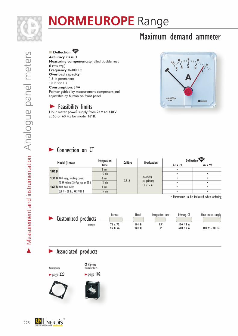
Accessories
> page 223
CT Current transformers
> page 102
80°90°
180°
250° 240°
360°
144°
60°54°105°
80°90°
180°
250° 240°
360°
144°
60°54°105°
Format Model Integration time Primary CT Hour meter supply
72 x 72 101 B 15’ 100 / 5 A 96 X 96 161 B 8’ 600 / 5 A 100 V - 60 Hz
> Connection on CT
Deflection Accuracy class: 3 Measuring component: spiralled double reed (I rms avg.) Frequency: 0-400 Hz Overload capacity: 1.5 In permanent 10 In for 1 s Consumption: 3 VA Pointer guided by measurement component and adjustable by button on front panel
> Feasibility limitsHour meter power supply from 24 V to 440 V at 50 or 60 Hz for model 161B.
Maximum demand ammeter
> Customized products
Integration Deflection
Model (I max) Time
Calibre Graduation 72 x 72 96 x 96
101B 8 min • 15 min • •131B With relay, breaking capacity 8 min • • 10 VA resistive, 250 Vac max or 0.5 A 15 min • •161B With hour meter 8 min • • 230 V - 50 Hz, 99,999.99 h 15 min • •
• Parameters to be indicated when ordering
7.5 A according to primary CT / 5 A
Example
228
NORMEUROPE Range
> Associated products> M
easu
rem
ent
and
inst
rum
enta
tion
Ana
logu
e pa
nel m
eter
s
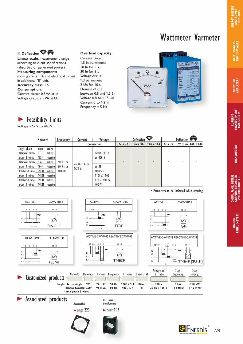
80°90°
180°
250° 240°
360°
144°
60°54°105°
80°90°
180°
250° 240°
360°
144°
60°54°105°
N
L1
ACTIVE CAW1011
8 9 1 6
+-
13 14
SINGLE
L1
ACTIVE CAW1035
89 1 6
+-
13 14
TE3F
L2
L3
10
L1
ACTIVE CAW1011
89 1 6
+-
13 14
TE4F
L2
L3
N
L1
REACTIVE CAW1031
8 9 1 6
+-
13 14
TE3/4F
L2
L3
NL1
ACTIVE CAW1032 REACTIVE CAV1032
89 1 5
+-
13 14
TNE3F
L2
L3
10
L1
ACTIVE CAW1032 REACTIVE CAV1032
89 14 5 6
+-
13 14
TNE4F [2U-3I]
L2
L3
10 2 3
N
WATTMETRE VARMETRE
PHASEMETRE
N
L1
PHASEMETRE CAPH1011
8 9 1 6
+-
13 14
MONO
L1
REACTIF CAPH1031
8 9 1 6
+-
13 14
TE3/4F
L2
L3
NL1
PHASEMETRE CA82
2 A 5 7
TNE
L2
L3
1 C3
N
6
BDEF
6 2
N
L1
ACTIVE CAW1011
8 9 1 6
+-
13 14
SINGLE
L1
ACTIVE CAW1035
89 1 6
+-
13 14
TE3F
L2
L3
10
L1
ACTIVE CAW1011
89 1 6
+-
13 14
TE4F
L2
L3
N
L1
REACTIVE CAW1031
8 9 1 6
+-
13 14
TE3/4F
L2
L3
NL1
ACTIVE CAW1032 REACTIVE CAV1032
89 1 5
+-
13 14
TNE3F
L2
L3
10
L1
ACTIVE CAW1032 REACTIVE CAV1032
89 14 5 6
+-
13 14
TNE4F [2U-3I]
L2
L3
10 2 3
N
WATTMETRE VARMETRE
PHASEMETRE
N
L1
PHASEMETRE CAPH1011
8 9 1 6
+-
13 14
MONO
L1
REACTIF CAPH1031
8 9 1 6
+-
13 14
TE3/4F
L2
L3
NL1
PHASEMETRE CA82
2 A 5 7
TNE
L2
L3
1 C3
N
6
BDEF
6 2
80°90°
180°
250° 240°
360°
144°
60°54°105°
80°90°
180°
250° 240°
360°
144°
60°54°105°
Deflection Linear scale, measurement range according to client specifications (absorbed or generated power) Measuring component: moving coil 2 mA and electrical circuit in additional "B" unit. Accuracy class: 1.5 Consumption: Current circuit 0.3 VA at In Voltage circuit 2.5 VA at Un
Overload capacity: Current circuit: 1.5 In permanent 10 In for 5 s 30 In for 3 s Voltage circuit: 1.3 permanent 2 Un for 10 s Domain of use: between 0.8 and 1.3 Sn Voltage 0.8 to 1.15 Un Current 0 to 1.2 In Frequency ± 5 Hz
Voltage or Scale Scale Network Deflection Format Frequency CT ratio Direct / VT VT ratio beginning ending
Examples Active single 90° 72 x 72 50 Hz 1000 / 5 A Direct 230 V 0 kW 250 kW Reactive balanced 250° 96 x 96 60 Hz 400 / 5 A TT 20 kV / 115 V - 12 Mvar + 12 MVar three-phase 3 wires
Network Frequency Current Voltage Deflection Deflection 72 x 72 96 x 96 144 x 144 72 x 72 96 x 96 144 x 144Single phase mono activeBalanced three- TE3F active direct 230 V phase 3 wires TE3F reactive or 400 VBalanced three- TE4F active 50 Hz or on TC/1 A or • • • • • • phase 4 wires TE4F reactive 60 Hz or TC/5 A on TTUnbalanced three- TNE3F active 400 Hz 100/√3 phase 3 wires TNE3F reactive 110/√3 100Unbalanced three- TNE4F active 110 - 230 or phase 4 wires TNE4F reactive 400 V
Wattmeter Varmeter
> Feasibility limitsVoltage 57.7 V to 440 V
> Customized products
• Parameters to be indicated when ordering
Connection
229
ANAL
OG
PANE
L M
ETER
S
CURR
ENT
TRAN
SFOR
MER
SAN
D SH
UNTS
DIGI
TAL
PANE
L M
ETER
SGR
APHI
C RE
CORD
ERSY
NCHR
OCOU
PLER
NETW
ORK
ANAL
YZER
STR
ANSD
UCER
SDA
TA L
OGGE
RS
AND
SOFT
WAR
E
ENER
GY M
ETER
S AN
D PO
WER
M
ONIT
ORS
> Associated productsAccessories
> page 223
CT Current transformers
> page 102
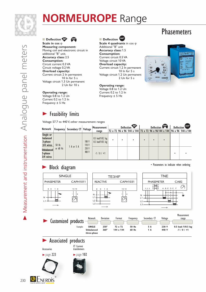
80°90°
180°
250° 240°
360°
144°
60°54°105°
80°90°
180°
250° 240°
360°
144°
60°54°105°
80°90°
180°
250° 240°
360°
144°
60°54°105°
REACTIVE CAPH1031PHASEMETER CAPH1011 PHASEMETER CA82
SINGLE
80°90°
180°
250° 240°
360°
144°
60°54°105°
80°90°
180°
250° 240°
360°
144°
60°54°105°
80°90°
180°
250° 240°
360°
144°
60°54°105°
Accessories
> page 223
CT Current transformers
> page 102
Measurement Network Deviation Format Frequency Secondary CT Voltage range
Examples SINGLE 250° 72 x 72 50 Hz 5 A 230 V 0.5 lead /1/0.5 lag Unbalanced 360° 144 x 144 60 Hz 1 A 440 V -1 / 0 / +1 three-phase
Phasemeters
> Block diagram • Parameters to indicate when ordering
Frequency Secondary CT Voltage Measurement Deflection Deflection Deflection range 72 x 72 96 x 96 144 x 144 72 x 72 96 x 96 144 x 144 96 x 96 144 x 144
Network
Unbalanced 3-phase3/4 wires
Single or balanced 3-phase3/4 wires
> Customized products
100 V 110 V 230 V 400 V
0.5 lead/1/0.2 lag0.5 lead/1/0.5 lag
-1 / 0 / +1
50 Hzor 60 Hz
1 A or 5 A
• • • • • •
• •
Deflection Scale in cos ϕ Measuring component: Moving coil and electronic circuit in additional "B" unit. Accuracy class: 2.5 Consumption: Circuit current 0.3 VA Circuit voltage 0.2 VA Overload capacity: Current circuit 2 In permanent 10 In for 5 s Voltage circuit 1.3 Un permanent 2 Un for 10 s
Operating range: Voltage 0.8 to 1.2 Un Current 0.2 to 1.2 In Frequency ± 5 Hz
Deflection Scale 4 quadrants in cos ϕ Additional "B" unit Accuracy class: 1.5 Consumption: Current circuit 0.5 VA Voltage circuit 10 VA Overload capacity: Current circuit 1.2 In permanent 10 In for 5 s Voltage circuit 1.2 Un permanent 2 Un for 5 s
Operating range: Voltage 0.8 to 1.2 Un Current 0.2 to 1.2 In Frequency ± 5 Hz
> Feasibility limitsVoltage 57.7 to 440 V, other measurement ranges
230
NORMEUROPE Range
> Associated products
> M
easu
rem
ent
and
inst
rum
enta
tion
Ana
logu
e pa
nel m
eter
s

80°90°
180°
250° 240°
360°
144°
60°54°105°
80°90°
180°
250° 240°
360°
144°
60°54°105°
80°90°
180°
250° 240°
360°
144°
60°54°105°
2
1
3
4
1
1
2
3
N
1'
2'
3'
N'
5
2
3
4
1
1
2
3
N
1'
2'
3'
N'
2
8
3
4
1
5 3 FILS
2 FILS
80°90°
180°
250° 240°
360°
144°
60°54°105°
80°90°
180°
250° 240°
360°
144°
60°54°105°
80°90°
180°
250° 240°
360°
144°
60°54°105°
Accessories
> page 223
Deflection Format 72 x 72 96 x 96 144 x 144Voltage Un 100/√3 V • • •100 V • BASS 0591 •230 V • BASS 0592 •400 V • BASS 0593 •
DeflectionFormat 96 x 96 144 x 144Frequency Voltage
50 Hz
100/√3 V • • 100 V SYNC 0686 • 230 V SYNC 0687 • 400 V • •
60 Hz
100/√3 V • • 100 V • • 230 V • • 400 V • •Phase lamp 2318635001 2318635001
Deflection`Accuracy class: 1.5 Three-phase network: 2-wire connection Consumption: Reference current 1.5 VA Circuit generator 5 VA Operating range: 0.8 to 1.2 Vn Overload capacity: 1.2 Vn permanent 2 Vn for 5 s Additional unit "B"
Accuracy class: 0.5 Consumption: 3 VA Operating range: 0.8 to 1.15 Un Measuring component: vibrating reed in field of coil Amplitude of vibration:proportional to V2
Deflection Accuracy class: 2.5 Consumption: 0.5 VA per circuit Frequency: 50-60 Hz Measurement range 0.75 to 1.25 Un Additional unit "B"
Synchronoscope Vibrating-reed double frequency meter
DifferentialVoltmeter
Deflection Format 72 x 72 96 x 96 144 x 144Voltage Un 100/√3 V • • •100 V • C250 0691 •230 V • • •400 V • • •
Phase Format Frequency Voltage lamp
Examples 144 x 144 50 Hz 100 V With 96 x 96 60 Hz 440 Without
Format Frequency Voltage
Examples 96 x 96 48-52 Hz 100/√3 V 72 x 72 58-62 Hz 415 V
Synchronizers
2 rows of 9 segmentsFormat 72 x 72 96 x 96 144 x 144Frequency Voltage
48-52 Hz
100/√3 V • • • 100 V • FL12 0677 • 230 V • FL12 0678 • 400 V • FL12 0679 •
58-62 Hz
100/√3 V • • • 100 V • • • 230 V • • • 400 V • • •
> Feasibility limitsVoltage 57.7 V to 440 V
> Feasibility limitsVoltage 57.7 V to 440 V
> Feasibility limitsMeasurement range,other...Voltage 57.7 V to 440 V
> Customized products > Customized products > Customized products Measurement Deflection Format Voltage range
Examples 90° 144 x 144 100 V ± 25% 250° 96 x 96 100/√3 V ± 50%
231
ANAL
OG
PANE
L M
ETER
S
CURR
ENT
TRAN
SFOR
MER
SAN
D SH
UNTS
DIGI
TAL
PANE
L M
ETER
SGR
APHI
C RE
CORD
ERSY
NCHR
OCOU
PLER
NETW
ORK
ANAL
YZER
STR
ANSD
UCER
SDA
TA L
OGGE
RS
AND
SOFT
WAR
E
ENER
GY M
ETER
S AN
D PO
WER
M
ONIT
ORS
> Associated products
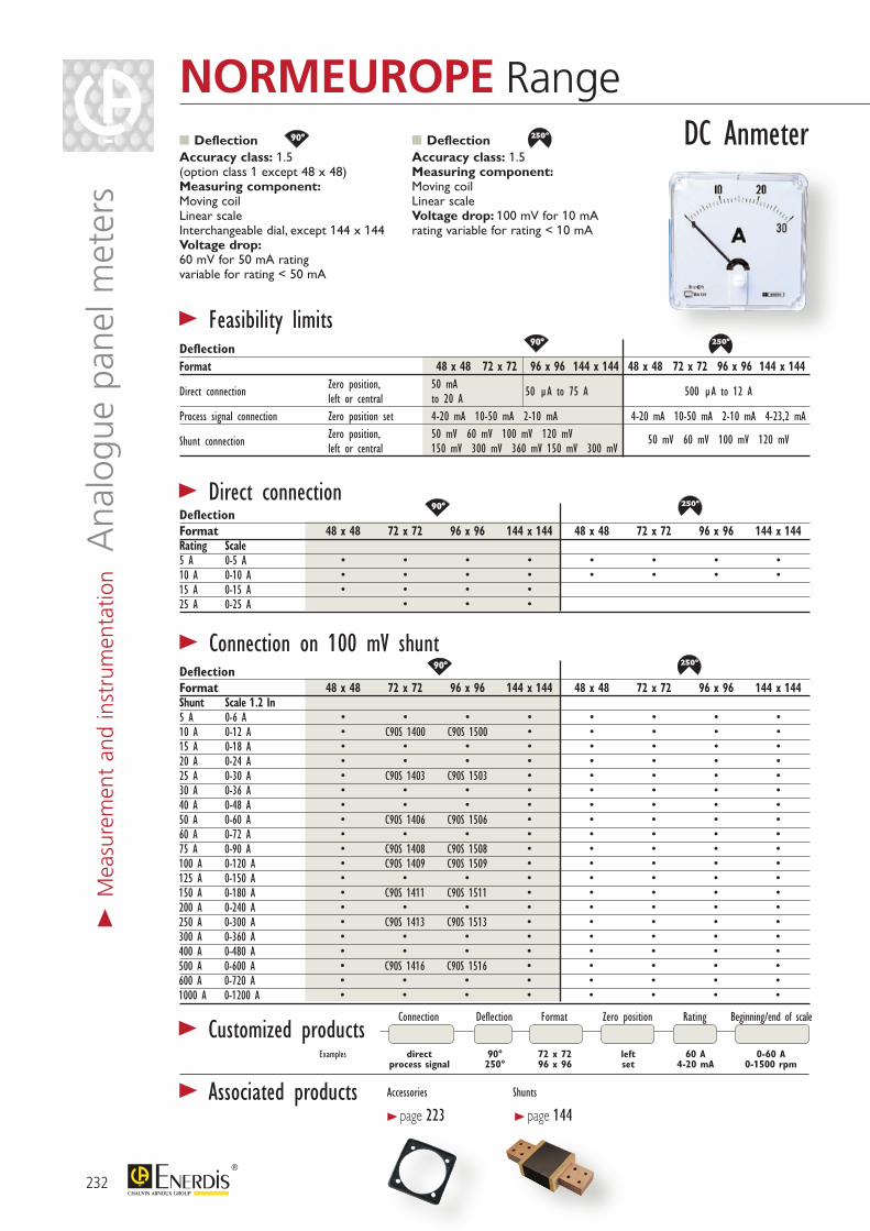
80°90°
180°
250° 240°
360°
144°
60°54°105°
80°90°
180°
250° 240°
360°
144°
60°54°105°
80°90°
180°
250° 240°
360°
144°
60°54°105°
80°90°
180°
250° 240°
360°
144°
60°54°105°
80°90°
180°
250° 240°
360°
144°
60°54°105°
80°90°
180°
250° 240°
360°
144°
60°54°105°
80°90°
180°
250° 240°
360°
144°
60°54°105°
80°90°
180°
250° 240°
360°
144°
60°54°105°
Deflection Format 48 x 48 72 x 72 96 x 96 144 x 144 48 x 48 72 x 72 96 x 96 144 x 144Shunt Scale 1.2 In 5 A 0-6 A • • • • • • • •10 A 0-12 A • C90S 1400 C90S 1500 • • • • •15 A 0-18 A • • • • • • • •20 A 0-24 A • • • • • • • •25 A 0-30 A • C90S 1403 C90S 1503 • • • • •30 A 0-36 A • • • • • • • •40 A 0-48 A • • • • • • • •50 A 0-60 A • C90S 1406 C90S 1506 • • • • •60 A 0-72 A • • • • • • • •75 A 0-90 A • C90S 1408 C90S 1508 • • • • •100 A 0-120 A • C90S 1409 C90S 1509 • • • • •125 A 0-150 A • • • • • • • •150 A 0-180 A • C90S 1411 C90S 1511 • • • • •200 A 0-240 A • • • • • • • •250 A 0-300 A • C90S 1413 C90S 1513 • • • • •300 A 0-360 A • • • • • • • •400 A 0-480 A • • • • • • • •500 A 0-600 A • C90S 1416 C90S 1516 • • • • •600 A 0-720 A • • • • • • • •1000 A 0-1200 A • • • • • • • •
Connection Deflection Format Zero position Rating Beginning/end of scale
Examples direct 90° 72 x 72 left 60 A 0-60 A process signal 250° 96 x 96 set 4-20 mA 0-1500 rpm
Deflection Accuracy class: 1.5 (option class 1 except 48 x 48) Measuring component: Moving coil Linear scale Interchangeable dial, except 144 x 144 Voltage drop: 60 mV for 50 mA rating variable for rating < 50 mA
Deflection Accuracy class: 1.5 Measuring component: Moving coil Linear scale Voltage drop: 100 mV for 10 mA rating variable for rating < 10 mA
> Feasibility limits
> Direct connection
> Connection on 100 mV shunt
DeflectionFormat 48 x 48 72 x 72 96 x 96 144 x 144 48 x 48 72 x 72 96 x 96 144 x 144
Direct connection Zero position, 50 mA left or central to 20 A 50 µA to 75 A 500 µA to 12 A
Process signal connection Zero position set 4-20 mA 10-50 mA 2-10 mA 4-20 mA 10-50 mA 2-10 mA 4-23,2 mA
Shunt connection Zero position, 50 mV 60 mV 100 mV 120 mV 50 mV 60 mV 100 mV 120 mV left or central 150 mV 300 mV 360 mV 150 mV 300 mV
Deflection Format 48 x 48 72 x 72 96 x 96 144 x 144 48 x 48 72 x 72 96 x 96 144 x 144Rating Scale 5 A 0-5 A • • • • • • • •10 A 0-10 A • • • • • • • •15 A 0-15 A • • • • 25 A 0-25 A • • •
DC Anmeter
> Customized products
> Associated products Accessories
> page 223Shunts
> page 144
232
NORMEUROPE Range>
Mea
sure
men
t an
d in
stru
men
tatio
n A
nalo
gue
pane
l met
ers
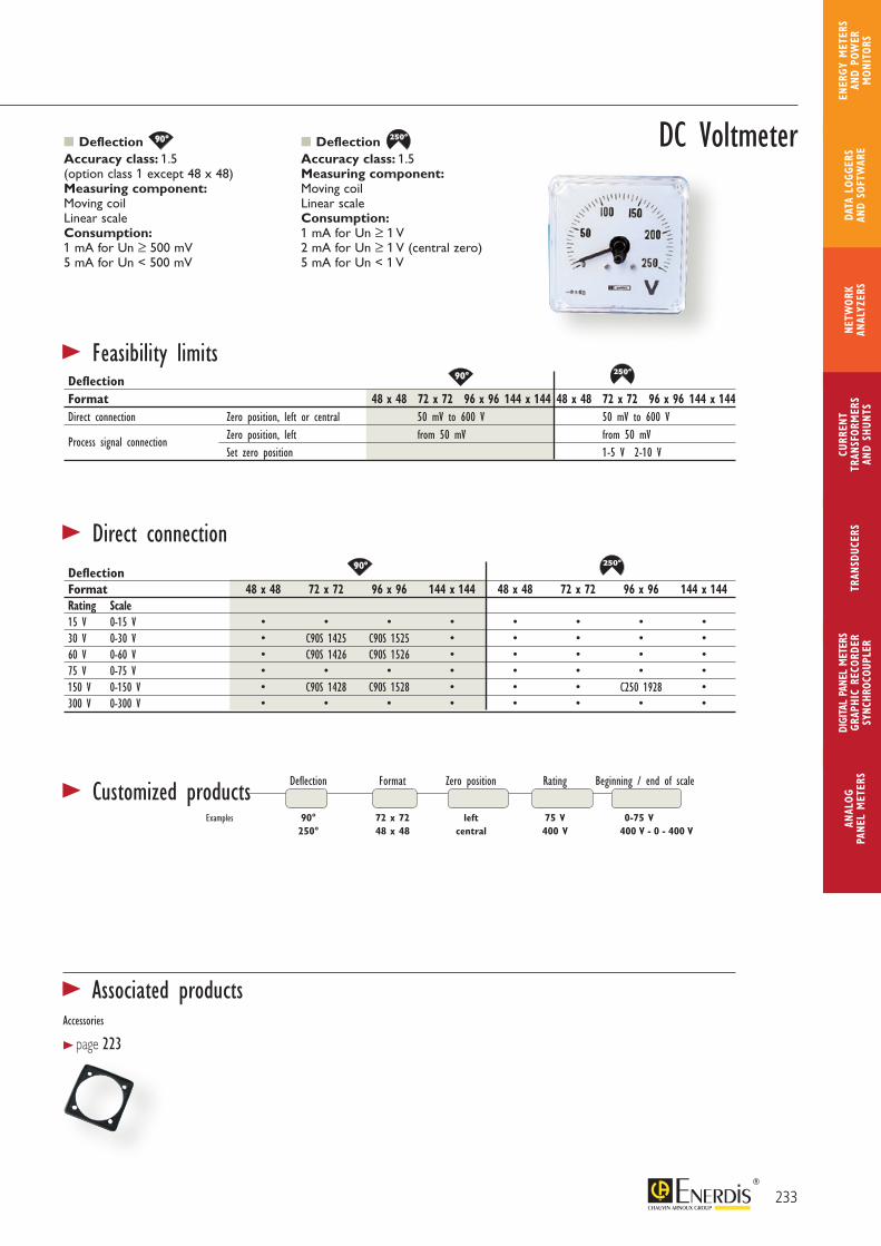
80°90°
180°
250° 240°
360°
144°
60°54°105°
80°90°
180°
250° 240°
360°
144°
60°54°105°
80°90°
180°
250° 240°
360°
144°
60°54°105°
80°90°
180°
250° 240°
360°
144°
60°54°105°
80°90°
180°
250° 240°
360°
144°
60°54°105°
80°90°
180°
250° 240°
360°
144°
60°54°105°
Accessories
> page 223
DeflectionFormat 48 x 48 72 x 72 96 x 96 144 x 144 48 x 48 72 x 72 96 x 96 144 x 144Direct connection Zero position, left or central 50 mV to 600 V 50 mV to 600 V
Process signal connection Zero position, left from 50 mV from 50 mV Set zero position 1-5 V 2-10 V
DeflectionFormat 48 x 48 72 x 72 96 x 96 144 x 144 48 x 48 72 x 72 96 x 96 144 x 144Rating Scale 15 V 0-15 V • • • • • • • •30 V 0-30 V • C90S 1425 C90S 1525 • • • • •60 V 0-60 V • C90S 1426 C90S 1526 • • • • •75 V 0-75 V • • • • • • • •150 V 0-150 V • C90S 1428 C90S 1528 • • • C250 1928 •300 V 0-300 V • • • • • • • •
Deflection Format Zero position Rating Beginning / end of scale
Examples 90° 72 x 72 left 75 V 0-75 V 250° 48 x 48 central 400 V 400 V - 0 - 400 V
Deflection Accuracy class: 1.5 (option class 1 except 48 x 48) Measuring component: Moving coil Linear scale Consumption: 1 mA for Un ≥ 500 mV 5 mA for Un < 500 mV
Deflection Accuracy class: 1.5 Measuring component: Moving coil Linear scale Consumption: 1 mA for Un ≥ 1 V 2 mA for Un ≥ 1 V (central zero) 5 mA for Un < 1 V
> Feasibility limits
> Direct connection
> Customized products
DC Voltmeter
233
ANAL
OG
PANE
L M
ETER
S
CURR
ENT
TRAN
SFOR
MER
SAN
D SH
UNTS
DIGI
TAL
PANE
L M
ETER
SGR
APHI
C RE
CORD
ERSY
NCHR
OCOU
PLER
NETW
ORK
ANAL
YZER
STR
ANSD
UCER
SDA
TA L
OGGE
RS
AND
SOFT
WAR
E
ENER
GY M
ETER
S AN
D PO
WER
M
ONIT
ORS
> Associated products
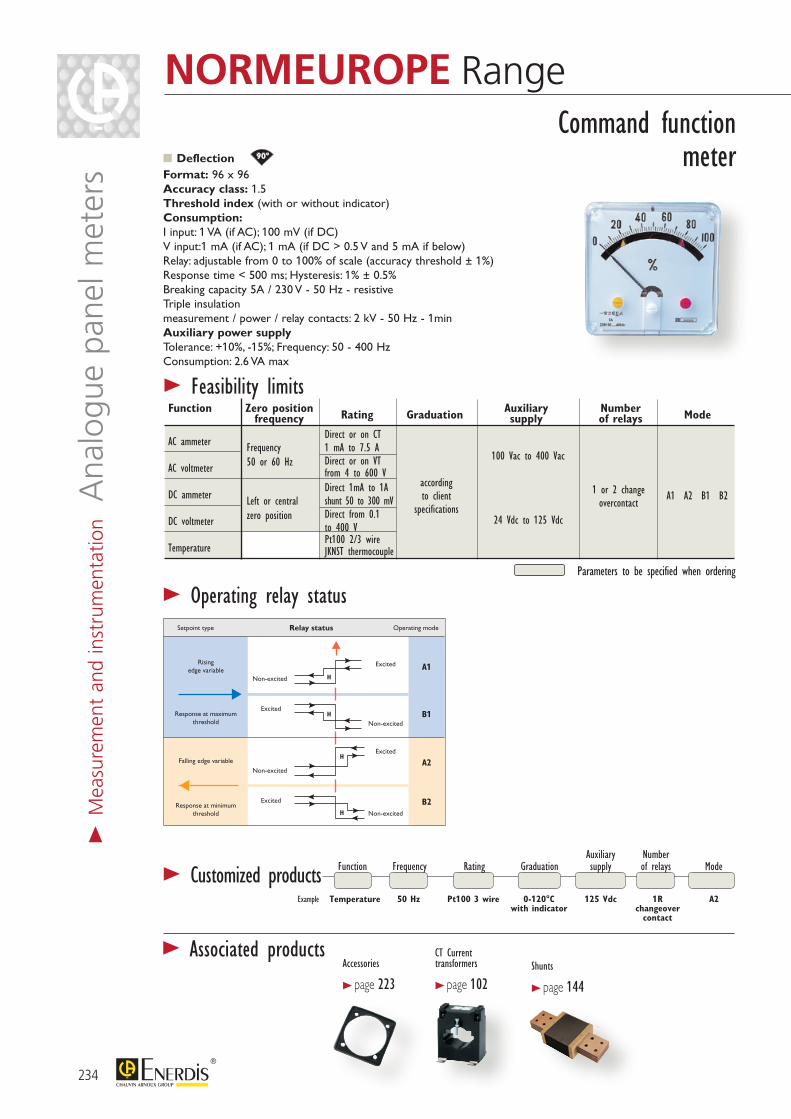
Excited
Excited
Non-excited
Non-excited
H
H
A1
B1
B2
A2Excited
Excited
Non-excited
Non-excited
H
H
Relay statusSetpoint type
Risingedge variable
Response at maximumthreshold
Falling edge variable
Response at minimumthreshold
Operating mode
80°90°
180°
250° 240°
360°
144°
60°54°105°
Accessories
> page 223
CT Current transformers
> page 102Shunts
> page 144
Auxiliary NumberFunction Frequency Rating Graduation supply of relays Mode
Deflection Format: 96 x 96 Accuracy class: 1.5 Threshold index (with or without indicator) Consumption: I input: 1 VA (if AC); 100 mV (if DC) V input:1 mA (if AC); 1 mA (if DC > 0.5 V and 5 mA if below) Relay: adjustable from 0 to 100% of scale (accuracy threshold ± 1%) Response time < 500 ms; Hysteresis: 1% ± 0.5% Breaking capacity 5A / 230 V - 50 Hz - resistive Triple insulation measurement / power / relay contacts: 2 kV - 50 Hz - 1min Auxiliary power supply Tolerance: +10%, -15%; Frequency: 50 - 400 Hz Consumption: 2.6 VA max
> Operating relay status
TemperatureExample Pt100 3 wire50 Hz 0-120°C with indicator
125 Vdc 1Rchangeover
contact
A2
Command functionmeter
> Customized products
> Feasibility limits Function Zero position Auxiliary Number frequency Rating Graduation supply of relays Mode
AC ammeter
AC voltmeter
DC ammeter
DC voltmeter
Temperature
Direct or on CT 1 mA to 7.5 ADirect or on VT from 4 to 600 VDirect 1mA to 1Ashunt 50 to 300 mV Direct from 0.1 to 400 VPt100 2/3 wireJKNST thermocouple
according to client
specifications
100 Vac to 400 Vac
24 Vdc to 125 Vdc
1 or 2 change overcontact
A1 A2 B1 B2
Frequency50 or 60 Hz
Left or centralzero position
Parameters to be specified when ordering
234
NORMEUROPE Range
> Associated products
> M
easu
rem
ent
and
inst
rum
enta
tion
Ana
logu
e pa
nel m
eter
s
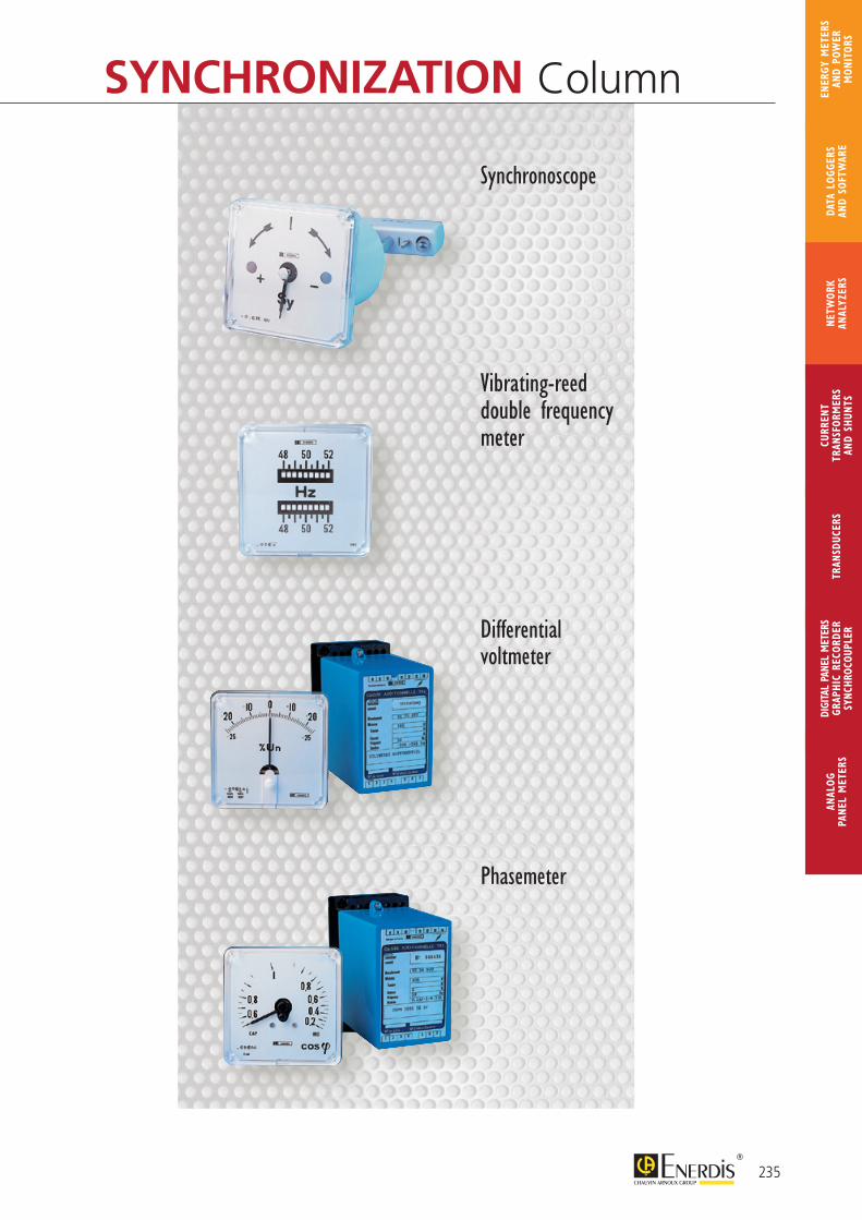
SYNCHRONIZATION Column
Synchronoscope
Vibrating-reed double frequency meter
Differential voltmeter
Phasemeter
235
ANAL
OG
PANE
L M
ETER
S
CURR
ENT
TRAN
SFOR
MER
SAN
D SH
UNTS
DIGI
TAL
PANE
L M
ETER
SGR
APHI
C RE
CORD
ERSY
NCHR
OCOU
PLER
NETW
ORK
ANAL
YZER
STR
ANSD
UCER
SDA
TA L
OGGE
RS
AND
SOFT
WAR
E
ENER
GY M
ETER
S AN
D PO
WER
M
ONIT
ORS

48 mm max. 70 mm Panel drilling
48 m
m
ø 48 mm
48 mm max. 70 mm Perçage du panneau
48 m
m
ø 48 mm
48 mm max. 70 mm Perçage du panneau
48 m
m
ø 48 mm
Reference standard: NFC 42310Display: without reset function, white on black background, decimals in red Height of digits: 4 mm AC and DC capacity: 99,999.99 h Operating indicator: scrolling 1/100 h every 36 s Motor in Vac/Vdc: pulse + electronic counter Consumption: 0.5 VA in 24 Vac/dc, 1.5 VA in 48 Vac/dc, 2 VA in 110/230 Vac, 6 VA in 400 Vac Operating range: Voltage Vac: -15% +10% Frequency: ± 5 Hz Voltage Vdc: ± 20%
Insulation: double Dielectric test voltage: 5.5 kV - 50 Hz - 1 min Environment: Operating temperature: -10°C to +60°C Relative humidity: < 95% at +45°C Protection rating on front panel: standard: IP50, option: IP55 Electromagnetic compatibility (emission and immunity): EN 61326-1 Mounting: Standard version: elastic joint IP55 version: joint + strap Weight: 180 g Connection: 6.35 Faston clips + terminal covers included
> General specifications
Format 48 x 48 (IP50) 48 x 48 (IP55)Frequency Voltage 24 V COHO 0606 COHO 1606
50 Hz 48 V COHO 0607 COHO 1607 110 V COHO 0608 COHO 1608 230/400 V COHO 0610 COHO 1610 24 V COHO 0627 COHO 1627
60 Hz 48 V COHO 0628 COHO 1628 110 V COHO 0629 COHO 1629 230/400 V COHO 0631 COHO 1631
DC 24 V COHO 0604 COHO 1604 48 V COHO 0605 COHO 1605
236
COHO RangeHour meters for totalling the operating time of machines or equipment for control and maintenance
> M
easu
rem
ent
and
inst
rum
enta
tion H
our
met
ers
PRODUCT ADVANTAGES
FOR SEVERE ENVIRONMENTS
ENHANCED RELIABILITY RANGE

46 +0-0, 5
LK RangeHour meters (7 or 8 digits) for totalling the operating time of machines or equipment for control and maintenance
Display: without reset function, white on black background,decimals in red Height of digits: 4 mm AC capacity: 99,999.99 h DC capacity: 999,999.99 h Operating indicator in Vac: ridged roll Operating indicator in Vdc: continuous scrolling 1/100h every 36 s Motor in Vac: synchronous Motor in Vdc: step-by-step Consumption: Vdc: ≤ 750 mW Vac: ≤ 1.65 VA
Insulation: single Dielectric test voltage: 2 kV - 50 Hz - 1 min Operating range: Voltage Vac: ± 10% Frequency: ± 10% Voltage Vdc: ± 10% Environment: Operating temperature: -15°C to +50°C Relative humidity: < 95% at +45°C Protection rating on front panel: IP52 Mounting: self-locking flange Weight: 50 g Connection: 6.35 lugs or Faston clips
> General specifications
Format 48 x 48 55 x 55 72 x 72Frequency Voltage 50 Hz 24 V LK4N 001N LK5N 001N LK7N 001N 48 V LK4N 003N LK5N 003N LK7N 003N 115 V LK4N 005N LK5N 005N LK7N 005N 230 V LK4N 007N LK5N 007N LK7N 007N 400 V LK4N 009N LK5N 009N LK7N 009N60 Hz 24 V LK4N 002N LK5N 002N LK7N 002N 48 V LK4N 004N LK5N 004N LK7N 004N 115 V LK4N 006N LK5N 006N LK7N 006N 230 V LK4N 008N LK5N 008N LK7N 008N 400 V LK4N 010N LK5N 010N LK7N 010NDC 10-30 V LK4N 011N LK5N 011N LK7N 011N 36-80 V LK4N 012N LK5N 012N LK7N 012N 110-130 V LK4N 013N LK5N 013N LK7N 013Nfront panel only LK5N 0000 LK7N 0000
Panel drilling
Ø 50,5
(except 48 x 48) (48 x 48)
237
ANAL
OG
PANE
L M
ETER
S
CURR
ENT
TRAN
SFOR
MER
SAN
D SH
UNTS
DIGI
TAL
PANE
L M
ETER
SGR
APHI
C RE
CORD
ERSY
NCHR
OCOU
PLER
NETW
ORK
ANAL
YZER
STR
ANSD
UCER
SDA
TA L
OGGE
RS
AND
SOFT
WAR
E
ENER
GY M
ETER
S AN
D PO
WER
M
ONIT
ORS
EASY TO INSTALL
ECONOMICAL
PRODUCT ADVANTAGES
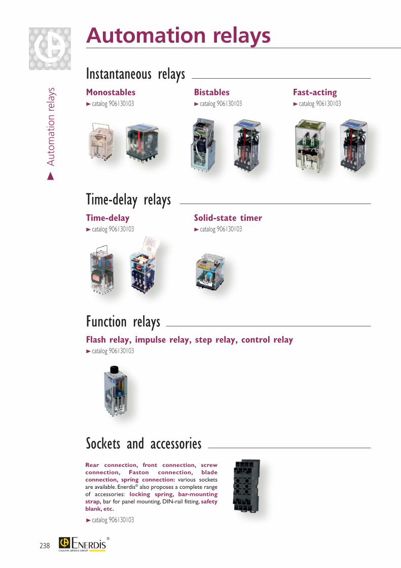
238
Automation relays>
Aut
omat
ion
rela
ys
Instantaneous relays
Function relays
Time-delay relays
Sockets and accessories
> catalog 906130103 > catalog 906130103 > catalog 906130103
Rear connection, front connection, screw connection, Faston connection, blade connection, spring connection: various sockets are available. Enerdis® also proposes a complete range of accessories: locking spring, bar-mounting strap, bar for panel mounting, DIN-rail fitting, safety blank, etc.
Monostables
Time-delay Solid-state timer
Flash relay, impulse relay, step relay, control relay
Bistables Fast-acting
> catalog 906130103
> catalog 906130103
> catalog 906130103
> catalog 906130103
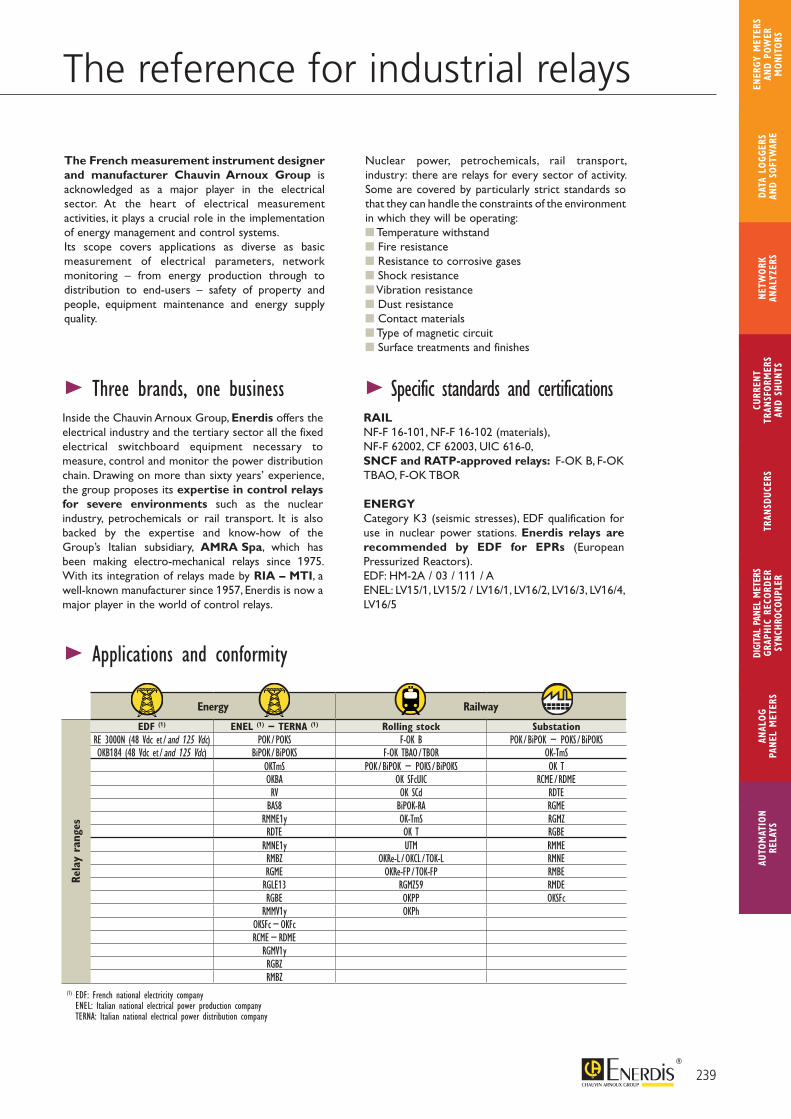
239
The reference for industrial relays
The French measurement instrument designer and manufacturer Chauvin Arnoux Group is acknowledged as a major player in the electrical sector. At the heart of electrical measurement activities, it plays a crucial role in the implementation of energy management and control systems.Its scope covers applications as diverse as basic measurement of electrical parameters, network monitoring – from energy production through to distribution to end-users – safety of property and people, equipment maintenance and energy supply quality.
> Three brands, one business Inside the Chauvin Arnoux Group, Enerdis offers the electrical industry and the tertiary sector all the fixed electrical switchboard equipment necessary to measure, control and monitor the power distribution chain. Drawing on more than sixty years’ experience, the group proposes its expertise in control relays for severe environments such as the nuclear industry, petrochemicals or rail transport. It is also backed by the expertise and know-how of the Group’s Italian subsidiary, AMRA Spa, which has been making electro-mechanical relays since 1975. With its integration of relays made by RIA – MTI, a well-known manufacturer since 1957, Enerdis is now a major player in the world of control relays.
> Applications and conformity
Nuclear power, petrochemicals, rail transport, industry: there are relays for every sector of activity. Some are covered by particularly strict standards so that they can handle the constraints of the environment in which they will be operating: Temperature withstand Fire resistance Resistance to corrosive gases Shock resistance Vibration resistance Dust resistance Contact materials Type of magnetic circuit Surface treatments and finishes
> Specific standards and certifications RAILNF-F 16-101, NF-F 16-102 (materials), NF-F 62002, CF 62003, UIC 616-0, SNCF and RATP-approved relays: F-OK B, F-OK TBAO, F-OK TBOR
ENERGYCategory K3 (seismic stresses), EDF qualification for use in nuclear power stations. Enerdis relays are recommended by EDF for EPRs (European Pressurized Reactors).EDF: HM-2A / 03 / 111 / AENEL: LV15/1, LV15/2 / LV16/1, LV16/2, LV16/3, LV16/4, LV16/5
Energy Railway
EDF (1) ENEL (1) − TERNA (1) Rolling stock SubstationRE 3000N (48 Vdc et / and 125 Vdc) POK / POKS F-OK B POK / BiPOK − POKS / BiPOKSOKB184 (48 Vdc et / and 125 Vdc) BiPOK / BiPOKS F-OK TBAO / TBOR OK-TmS
OKTmS POK / BiPOK − POKS / BiPOKS OK TOKBA OK SFcUIC RCME / RDMERV OK SCd RDTEBAS8 BiPOK-RA RGME
RMME1y OK-TmS RGMZRDTE OK T RGBE
RMNE1y UTM RMMERMBZ OKRe-L / OKCL / TOK-L RMNERGME OKRe-FP / TOK-FP RMBERGLE13 RGMZ59 RMDERGBE OKPP OKSFc
RMMV1y OKPhOKSFc − OKFcRCME − RDME
RGMV1yRGBZRMBZ
(1) EDF: French national electricity company ENEL: Italian national electrical power production company TERNA: Italian national electrical power distribution company
Rela
y ra
nges
Fast-acting
AUTO
MAT
ION
RELA
YSAN
ALOG
PA
NEL
MET
ERS
CURR
ENT
TRAN
SFOR
MER
SAN
D SH
UNTS
DIGI
TAL
PANE
L M
ETER
SGR
APHI
C RE
CORD
ERSY
NCHR
OCOU
PLER
NETW
ORK
ANAL
YZER
STR
ANSD
UCER
SDA
TA L
OGGE
RS
AND
SOFT
WAR
E
ENER
GY M
ETER
S AN
D PO
WER
M
ONIT
ORS
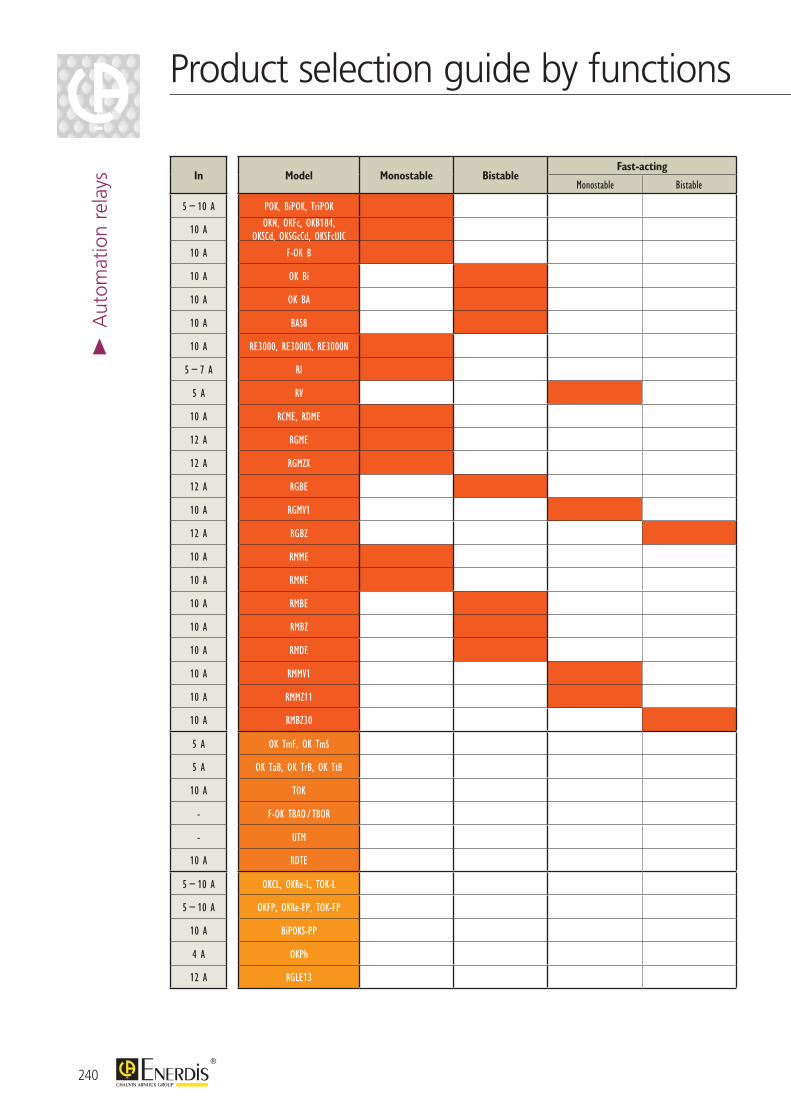
240
In Model Monostable BistableFast-acting
Time-delayFunction Solid-state
timerMonostable Bistable Flash Impulse Step by step Control
5 − 10 A POK, BiPOK, TriPOK
10 A OKN, OKFc, OKB184, OKSCd, OKSGcCd, OKSFcUIC
10 A F-OK B
10 A OK Bi
10 A OK BA
10 A BAS8
10 A RE3000, RE3000S, RE3000N
5 − 7 A RI
5 A RV
10 A RCME, RDME
12 A RGME
12 A RGMZX
12 A RGBE
10 A RGMV1
12 A RGBZ
10 A RMME
10 A RMNE
10 A RMBE
10 A RMBZ
10 A RMDE
10 A RMMV1
10 A RMMZ11
10 A RMBZ30
5 A OK TmF, OK TmS
5 A OK TaB, OK TrB, OK TtB
10 A TOK
- F-OK TBAO / TBOR
- UTM
10 A RDTE
5 − 10 A OKCL, OKRe-L, TOK-L
5 − 10 A OKFP, OKRe-FP, TOK-FP
10 A BiPOKS-PP
4 A OKPh
12 A RGLE13
Product selection guide by functions>
Aut
omat
ion
rela
ys
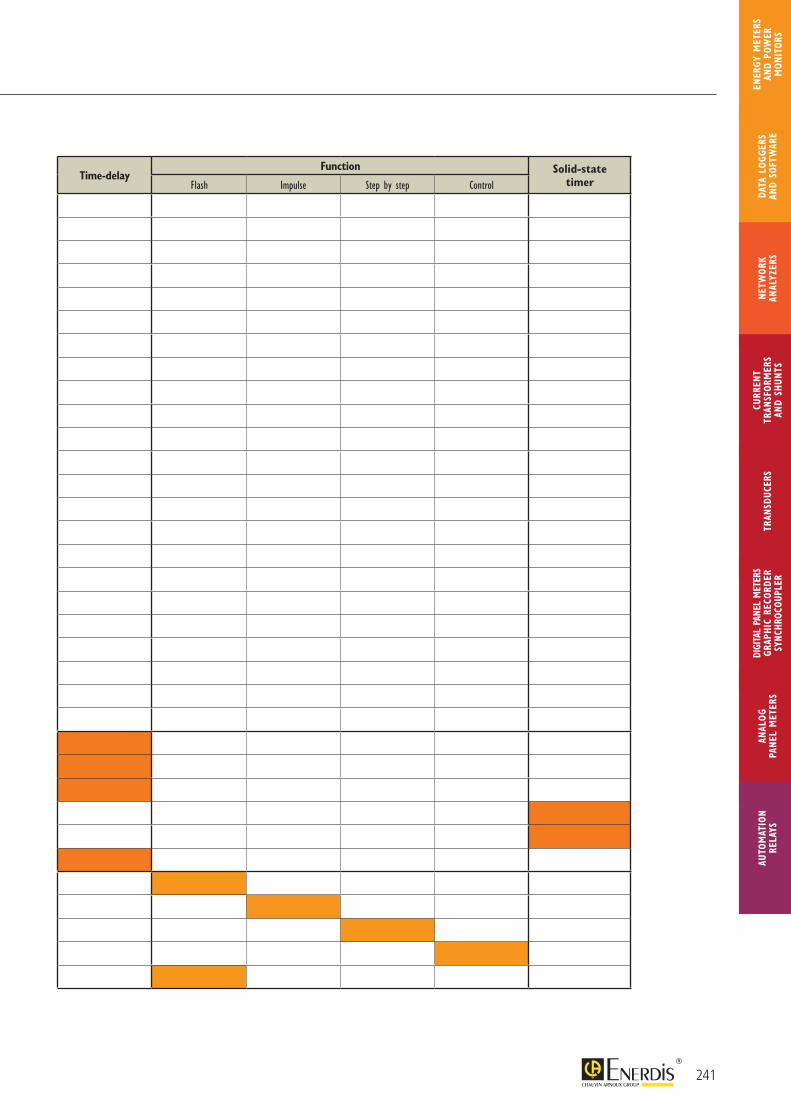
241
In Model Monostable BistableFast-acting
Time-delayFunction Solid-state
timerMonostable Bistable Flash Impulse Step by step Control
5 − 10 A POK, BiPOK, TriPOK
10 A OKN, OKFc, OKB184, OKSCd, OKSGcCd, OKSFcUIC
10 A F-OK B
10 A OK Bi
10 A OK BA
10 A BAS8
10 A RE3000, RE3000S, RE3000N
5 − 7 A RI
5 A RV
10 A RCME, RDME
12 A RGME
12 A RGMZX
12 A RGBE
10 A RGMV1
12 A RGBZ
10 A RMME
10 A RMNE
10 A RMBE
10 A RMBZ
10 A RMDE
10 A RMMV1
10 A RMMZ11
10 A RMBZ30
5 A OK TmF, OK TmS
5 A OK TaB, OK TrB, OK TtB
10 A TOK
- F-OK TBAO / TBOR
- UTM
10 A RDTE
5 − 10 A OKCL, OKRe-L, TOK-L
5 − 10 A OKFP, OKRe-FP, TOK-FP
10 A BiPOKS-PP
4 A OKPh
12 A RGLE13
AUTO
MAT
ION
RELA
YSAN
ALOG
PA
NEL
MET
ERS
CURR
ENT
TRAN
SFOR
MER
SAN
D SH
UNTS
DIGI
TAL
PANE
L M
ETER
SGR
APHI
C RE
CORD
ERSY
NCHR
OCOU
PLER
NETW
ORK
ANAL
YZER
STR
ANSD
UCER
SDA
TA L
OGGE
RS
AND
SOFT
WAR
E
ENER
GY M
ETER
S AN
D PO
WER
M
ONIT
ORS
Cl classAC or ac alternating currentCT current transformerDC or dc direct currentE energyEact active energyEapp apparent energyEreact reactive energyFS full scaleg acceleration of gravity (9.81 m/s2)Gb gigabyteHV high-voltageI current (A, kA)I/O input/outputIEC International Electrotechnical CommissionIn nominal currentIP protection levelIR infraredK Kelvin temperature gradientKb kilobyteLCD liquid crystal displayLED light-emitting diodeLV low voltageMb megabytemin minutemm millimetrems millisecondMV medium voltageNC “normally closed (“break” relay contact)”NO “normally open (“make” relay contact)”P active power (W, kW, MW)PC personal computerPF power factorPID proportional integral derivativePPM parts per million diameter (in mm)PR protection rating (often expressed as IP)Q reactive powerR reading accuracy (in %)RMS root mean squareS apparent power (in VA, kVA, MVA...)s secondSTN switched telephone networkTC thermocoupleTHD total harmonic distortionTRMS True RMSU phase-phase voltageUn nominal voltageV phase-neutral voltageVT (or PT) voltage or potential transformer
Index of abbreviations
242
> In
dex
243
INDE
XAU
TOM
ATIO
N RE
LAYS
ANAL
OG
PANE
L M
ETER
S
CURR
ENT
TRAN
SFOR
MER
SAN
D SH
UNTS
DIGI
TAL
PANE
L M
ETER
SGR
APHI
C RE
CORD
ERSY
NCHR
OCOU
PLER
NETW
ORK
ANAL
YZER
STR
ANSD
UCER
SDA
TA L
OGGE
RS
AND
SOFT
WAR
E
MET
ERS
AND
POW
ER
MON
ITOR
S
µDIGI 1 ..................................................................................................................................................... page 194
µDIGI 2 ..................................................................................................................................................... page 198
76-2 .............................................................................................................................................................. page 145
77-2 .............................................................................................................................................................. page 145
AC ammeter ......................................................................................................................................... page 224
Analogue panel meters .................................................................................................................. page 218
Analogue transducers ..................................................................................................................... page 184
Analyzers .................................................................................................................................................. page 78
C.A 2100 ................................................................................................................................................. Consult us
C.A 2150 ................................................................................................................................................. page 202
C.A 2200 ................................................................................................................................................. page 206
C.A 3000 ................................................................................................................................................. Consult us
Capacitor bank .................................................................................................................................... Consult us
CCT remote readable pulse receiver ................................................................................ page 66
CDT remote readable meter ................................................................................................... Consult us
COHO ...................................................................................................................................................... page 236
Command function meter (analogue panel meter) ................................................. page 218
Communication modules (for ULYS TDA80 - MD80 - TTA) ........................... page 36
Communication solutions ........................................................................................................... page 77
Control relays....................................................................................................................................... Consult us
Current summation ......................................................................................................................... page 141
Current transformers ..................................................................................................................... page 102
CVAI ............................................................................................................................................................ Consult us
C.A 3420 ................................................................................................................................................. page 182
Data logger ............................................................................................................................................. page 56
DC ammeter ........................................................................................................................................ page 232
DC voltmeter ....................................................................................................................................... page 233
Digital Panel meters ......................................................................................................................... page 188
Digital transducers ............................................................................................................................ page 152
Electrical power quality analizers ........................................................................................... page 78
ELOG ......................................................................................................................................................... page 58
Energy management (software) .............................................................................................. page 68
Energy meters ...................................................................................................................................... page 6
Energy performance ........................................................................................................................ page 4
ENERIUM ................................................................................................................................................ page 38
ENERTRACE ......................................................................................................................................... page 210
E.ONLINE ............................................................................................................................................... page 68
Index
#
A
C
D
E
E.QUAL PREMIUM .......................................................................................................................... page 92
E.QUAL PREMIUM SERVER ..................................................................................................... page 92
E.SET ........................................................................................................................................................... page 49
E.VIEW ...................................................................................................................................................... page 50
E.VIEW+ ................................................................................................................................................... page 51
Flashing relays ....................................................................................................................................... Catalog 906 130 103
Frequency meters ............................................................................................................................. page 227
Function relays ..................................................................................................................................... Catalog 906 130 103
Graphic recorder ............................................................................................................................... page 210
Harmonic filters .................................................................................................................................. Consult us
Hour meter ........................................................................................................................................... page 236
Instantaneous relays ......................................................................................................................... Catalog 906 130 103
JVM 15 ....................................................................................................................................................... page 141
JVO ............................................................................................................................................................... page 125
JVP................................................................................................................................................................. page 128
JVR ................................................................................................................................................................ page 124
JVS ................................................................................................................................................................. page 130
LK .................................................................................................................................................................. page 237
LOGIC....................................................................................................................................................... Consult us
Management and analysis software ...................................................................................... page 68
MAP ............................................................................................................................................................. page 78
Maximum demand ammeter ..................................................................................................... page 228
MD65 ......................................................................................................................................................... page 24
MD80 ......................................................................................................................................................... page 26
Measurement and instrumentation ...................................................................................... page 101
Measurement current transformers .................................................................................... page 102
MEMO 3 .................................................................................................................................................. page 20
MEMO 4 .................................................................................................................................................. page 22
Metering solutions ............................................................................................................................ page 52
MICAR 2 .................................................................................................................................................. page 174
MID .............................................................................................................................................................. page 16
MODUL’M .............................................................................................................................................. Consult us
Modular energy meter ................................................................................................................. page 6
MODULIC analogue transducers ......................................................................................... Consult us
Monostable instantaneous relays ........................................................................................... Catalog 906 130 103
Multi-display units .............................................................................................................................. Consult us
F
G
H
J
L
M
I
244
Index >
Inde
x
Network analyzers ........................................................................................................................... page 78
Network analyzer software ....................................................................................................... page 92
Network quality ................................................................................................................................. page 78
NODUS ................................................................................................................................................... Consult us
NORMEUROPE ................................................................................................................................. page 222
Phase meters......................................................................................................................................... pages 188, 218
POWER .................................................................................................................................................... Consult us
Power factor correction ............................................................................................................... Consult us
Power monitors.................................................................................................................................. page 38
Probe (thermocouple) ................................................................................................................. See Pyrocontrole Catalog
Process recorder ............................................................................................................................... page 210
Protection relays ................................................................................................................................ Consult us
PRTC ........................................................................................................................................................... page 142
Pulse receiver ....................................................................................................................................... page 66
Quality analyzers ................................................................................................................................ page 78
QUAL-SRT ............................................................................................................................................. page 92
QUAL-VIEW ........................................................................................................................................ page 92
RecDisplay ............................................................................................................................................... Consult us
Recorder .................................................................................................................................................. page 210
Relays .......................................................................................................................................................... Catalog 906 130 103
Relay sockets ......................................................................................................................................... Catalog 906 130 103
Remote data retrieval solutions .............................................................................................. page 56
Remote-readable pulse receiver ............................................................................................. page 56
RENOV ENERGY ............................................................................................................................. page 52
SESAME Programming software ........................................................................................... Consult us
SHEL ............................................................................................................................................................ page 149
SHMI ........................................................................................................................................................... page 147
SHMO ........................................................................................................................................................ page 150
Shunts ......................................................................................................................................................... page 144
Software
for ENERIUM .................................................................................................................. page 48
for meter and power monitor ........................................................................... page 68
for network analizer .................................................................................................. page 92
for transducer ................................................................................................................. page 172
for TRIAD2 ....................................................................................................................... page 172
energy management ................................................................................................... page 68
network supervision .................................................................................................. page 68
Split core transformers ................................................................................................................. page 118
Switches .................................................................................................................................................... Consult us
Synchrocoupleur ................................................................................................................................ page 214
Synchronization instruments ..................................................................................................... pages 18, 218
Synchronizers ....................................................................................................................................... pages 188, 218
N
P
Q
R
S
245
INDE
XAU
TOM
ATIO
N RE
LAYS
ANAL
OG
PANE
L M
ETER
S
CURR
ENT
TRAN
SFOR
MER
SAN
D SH
UNTS
DIGI
TAL
PANE
L M
ETER
SGR
APHI
C RE
CORD
ERSY
NCHR
OCOU
PLER
NETW
ORK
ANAL
YZER
STR
ANSD
UCER
SDA
TA L
OGGE
RS
AND
SOFT
WAR
E
MET
ERS
AND
POW
ER
MON
ITOR
S
Tachometric movement sensor .............................................................................................. Consult us
TC CLIP ................................................................................................................................................... page 112
TCR current transformers ......................................................................................................... page 113
TCRO current transformers ................................................................................................... page 118
TCS .............................................................................................................................................................. Consult us
TD80 .......................................................................................................................................................... page 28
TDA80 ....................................................................................................................................................... page 32
Timer .......................................................................................................................................................... page 190
TONIC ...................................................................................................................................................... Consult us
Transducers ............................................................................................................................................ page 152
Transformers ......................................................................................................................................... page 102
Transformer short-circuit switch ........................................................................................... page 142
TRI500 ....................................................................................................................................................... page 139
TRI700 ....................................................................................................................................................... page 140
TRIAD 2 ................................................................................................................................................... page 158
TRIADJUST 2 software ................................................................................................................ page 172
T82 analogue transducers ........................................................................................................... Consult us
TSPU/TSPI ............................................................................................................................................... page 185
TSP2 ............................................................................................................................................................ page 184
TT ................................................................................................................................................................. page 30
TTA .............................................................................................................................................................. page 34
ULYS ............................................................................................................................................................ page 6
ULYSCOM .............................................................................................................................................. page 36
Varmeters ................................................................................................................................................ page 229
VISUALL ................................................................................................................................................... Consult us
Voltmeters .............................................................................................................................................. pages 188, 218
Wattmeters/Varmeters ................................................................................................................. page 229
Web-box data logger ...................................................................................................................... page 58
T
V
U
W
246
Index >
Inde
x

CHAUVIN ARNOUXTest et Mesure190, rue Championnet75876 PARIS Cedex 18 FRANCETél. : +33 1 44 85 44 85Fax : +33 1 46 27 73 [email protected]
PYROCONTROLE6 bis, av du Docteur Schweitzer69881 MEYZIEU Cedex FRANCETél. : +33 4 72 14 15 40Fax : +33 4 72 14 15 [email protected]
MANUMESURE45 route de Saint Eugène14130 REUX FRANCETél. : +33 2 31 64 51 00Fax : +33 2 31 64 51 [email protected]
10 SUBSIDIARIES WORLDWIDE
906
131
080
- Ed
. 9 -
05/
2015
- N
on-c
ontr
actu
al d
ocum
ent
- Sp
ecifi
catio
ns a
re t
o be
con
firm
ed a
t tim
e of
ord
erin
g -
Phot
os a
nd d
iagr
ams
are
non-
cont
ract
ual.
See the complete automation relays offering to meet all the requirements of industry, the energy sector, rail, etc.
AUSTRIAChauvin Arnoux Ges.m.b.HSlamastrasse 29/2/41230 WIENTel.: +43 1 61 61 9 61Fax: +43 1 61 61 9 [email protected] www.chauvin-arnoux.at
CHINAShanghai Pu-JiangEnerdis Instruments Co. Ltd3 Floor, Building 1 N° 381 Xiang De Road200081 SHANGHAITel.: +86 21 65 21 51 96Fax: +86 21 65 21 61 [email protected]
GERMANYChauvin Arnoux GmbHOhmstraße 177694 KEHL / RHEINTel.: +49 07851 99 26-0Fax: +49 07851 99 [email protected] www.chauvin-arnoux.de
ITALYAMRA SpAVia Sant’Ambrogio, 23 20846 MACHERIO (MB)Tel.: +39 039 245 75 45Fax: +39 039 481 [email protected] www.chauvin-arnoux.it
MIDDLE EASTChauvin Arnoux Middle EastPO Box 60-154 1241 2020 JAL EL DIB (Beirut) - LEBANONTel.: +961 1 890 425 Fax: +961 1 890 [email protected]
SPAINChauvin Arnoux Iberica SAC/ Roger de Flor N°293, 1a Planta08025 BARCELONATel.: +34 902 20 22 26Fax: +34 93 459 14 [email protected] www.chauvin-arnoux.es
SCANDINAVIA CA Mätsystem ABSjöflygvägen 35SE-183 62 TABYTel.: +46 8 50 52 68 00Fax: +46 8 50 52 68 [email protected]
SWITZERLANDChauvin Arnoux AGMoosacherstrasse 15 8804 AU / ZH Tel.: +41 44 727 75 55Fax: +41 44 727 75 [email protected] www.chauvin-arnoux.ch
UNITED KINGDOMChauvin Arnoux LtdUnit 1 Nelson Ct, Flagship Sq Shaw Cross Business Pk, DewsburyWest Yorkshire - WF12 7THTel:+44 1924 460 494 Fax: +44 1924 455 [email protected] www.chauvin-arnoux.com
USAChauvin Arnoux Inc d.b.a AEMC Instruments200 Foxborough Blvd. Foxborough - MA 02035Tel.: +1 (508) 698-2115Fax: +1 (508) [email protected] www.aemc.com
ENERDIS A local service for a better service
A centralized contact
ENERDIS16, rue Georges Besse - Silic 4492182 ANTONY CedexFRANCEwww.enerdis.com
FranceTel.: 01 75 60 10 30Fax: 01 46 66 62 [email protected]
InternationalTel.: +33 1 75 60 10 30 Fax: +33 1 46 66 62 [email protected]
Catalogue Pyro Capteurs 2013 GB.indd 1 13/02/2013 11:06:41
General catalog
2015/2015 Gen
eral
cat
alo
g 2
015-
2016