Embed Size (px)
Citation preview
1
A compact, multi-sensor laser scanning head for processing and monitoring micro-spot welding
Moustapha HAFEZ*, Karin JULLIARD*, Sylvain GROSSMANN*, Lino
OLIVETTA*, Thomas SIDLER*, René-Paul SALATHE*, Hans-Peter SCHWOB**, Toon BLOM***, and Willem HOVING***
*Institut d'Optique Appliquée, Département de Microtechnique, Ecole Polytechnique Fédérale de
Lausanne, BM, 1015 Lausanne, Switzerland Email: [email protected]
Email: [email protected] **Lasag Industrial Lasers, Thun, Switzerland.
***Philips Centre for Manufacturing Technology,5600 MD Eindhoven, The Netherlands.
Abstract: In order to improve the reliability of micro-spot welding of metal parts in production such as e. g. in electron guns for TV picture tubes, real-time information about the evolution of the welding process should be available to allow on-line modification of the laser parameters. Such information can be derived from a set of sensors that are mounted on a laser-scanning head. Different sensors are used to monitor the optical fiber output power to determine the evolution of temperature during the spot welding process, to measure plasma emission and back-reflected laser light. A vision channel and a CCD camera are used to control the position of the laser spot on the parts to be processed. The compact scanning head is composed of a tip/tilt laser scanner, a collimating lens and a focusing lens. The scanner is fast steering, with a bandwidth of 700Hz, and can tilt by ±3.5° with a repeatability better than 50µrad. The settling time for maximum deflection is less than 10ms. The scanning lens is a newly developed focusing lens designed to replace commercial cumbersome scanning lenses such as F-θ lenses, which have large volume, weight and price. This lens is based on the well-known Cooke triplet design and guarantees a constant shape of the spot all over the scan surface and is specially well suited for high power beam delivery. The scan field achieved by the system is limited to 25mm x 25mm. The laser used for this application is a pulsed Nd:YAG laser delivered by an optical fiber to the optical head. However, the system can be adapted to different types of lasers. Laser micro-spot welding on copper substrate has been performed in the frame of the Brite-Euram project MAIL. Smaller tolerances (a factor of 2 less) on the spot diameters were obtained in the case of a sensor controlled operation compared to the case where sensor control is not used. Keywords: Compact head, micro-spot welding, multi-sensors, tip/tilt scanner, new focusing lens.for material processing applications.
1. Introduction Many material processing applications use fiber optical beam delivery of the laser power to the processing equipment. Fiber beam delivery has become a standard technique in recent years for processes such as welding, which require relatively low beam quality but highly uniform beams. This is mainly due to the ease of manipulation and the high flexibility of optical fibers in light guiding. A further advantage of fiber delivery is its tendency to circularise and depolarise the beam, leading to a near flat top-hat beam profile with high reproducibility.
These properties are of prime importance for reliable industrial process control in various laser materials processing applications. Moreover, fiber beam delivery leads to more compact beam handling systems. In fact, diverse applications are restricted with a limited volume of space. Therefore, the need for more compact high precision manipulators and measuring systems is also increasing. A compact, multi-sensor laser scanning head for processing and monitoring micro-spot welding is presented in this paper. In order to improve the reliability of micro-spot welding of metal parts in production such as e. g. in electron guns for TV picture tubes, real-time
2
information about the evolution of the welding process should be available to allow on-line modification of the laser parameters. The optical head proposed is based on fiber optical beam delivery of the laser power. The main modules are a tip/tilt high-power laser scanner to control the laser spot position and a set of Silicon and Germanium sensors to monitor and control the micro-spot welding process. For more than two decades, galvanometer scanners have been the usual solution for laser scanning systems [1]. In order to scan in two directions, two rotating scanners must be used. One of the mirrors must be larger to allow the scan of the laser beam generated by the rotation of the other mirror. The tip/tilt scanner used in this system has a single mirror that achieves the two degrees of freedom in rotation and can steer large beams up to 25 mm in diameter. The design principles of this scanner are presented in [2]. 1. Set-up The optical head is based on a pre-objective laser scan system. In this configuration, the tip/tilt scanner is placed before the focusing optics (see Fig. 1).
Figure 1- Compact multi-sensor laser scanning head. S1 is the temperature sensor composed of two photodiodes (Si and Ge) in a sandwich configuration. S2 is the plume sensor, S3 detects the back-reflected light of Nd:YAG on the irradiated part, and S4 is the monitoring sensor for the laser to detect pulse shape.
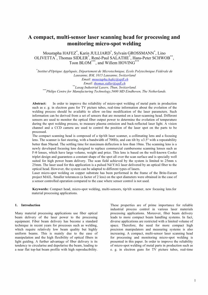
The optical fiber is fixed on the head by means of the fiber connector. The laser beam is collimated by a first lens and is then steered and accurately positioned by the scanner. The focusing lens has been designed to replace commercial cumbersome scanning lenses such as F-θ lenses, which have large volume, weight and price. This new lens guarantees a constant shape of the spot all over the scan surface and is specially well suited for high power beam delivery. A ring composed of 20 LEDs emitting at a wavelength of 620 nm is fixed around the lens and is used to illuminate the working plane as indicated in Fig.1. This configuration provides a homogeneous and optimised illumination for the vision module. The CCD camera is mounted on the system to monitor the working plane, as e. g. for aim and shoot applications. A set of Silicon and Germanium sensors are mounted on the optical head to determine the evolution of temperature, the plasma, the back reflected light and the pulse shape during the spot welding process. The laser source used in the experiments is a pulsed Nd:YAG laser 150/220W (Lasag SLS 200) and the optical fiber has a fiber core diameter of 200 µm. 2. Single mirror tip-tilt scanner In order to construct a compact high performance scanner, the different components must be carefully optimized. In this sense, the moving part, essentially the mirror and the actuators must be designed to minimal inertia for maximum motor force and mechanical stiffness. Moving magnet linear motors arranged in a push-pull, pure torque delivering configuration are used as actuators. A cone-ball bearing with a (half) sapphire ball glued to the moving part and a POM cone on the stationary part assumes a minimum friction and maximum rigidity suspension.
Figure 2- Compact single mirror tip-tilt scanner with housing removed. The overall dimensions of the scanner are 30x40x50 mm.
3
The figure 2 shows the scanner with removed outer housing, the mirror and the motor coils can clearly be seen. Two preload fixed holding magnets take the mirror securely in place even in an upwards down configuration and hold the rotation around the mirror axis fixed, leaving only the two desired tip and tilt rotations free. As no elastic restoring force is present, the scanner can only be used in a closed control loop configuration. The actual mirror position is measured with a laser light pen reflected by the back mirror surface and falling onto a 2-dimensional position sensitive detector (PSD), yielding the two electrical position signals for the closed loop control.
-30.00
-25.00
-20.00
-15.00
-10.00
-5.000
0.000
5.000
10.00
-200
-150
-100
-50
0
50
1 101 102 103 104
Amplitude
Phase
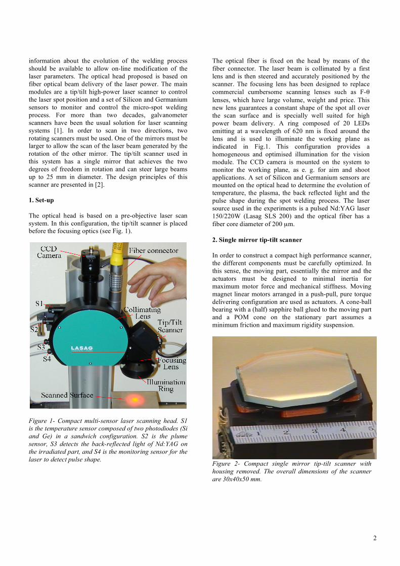
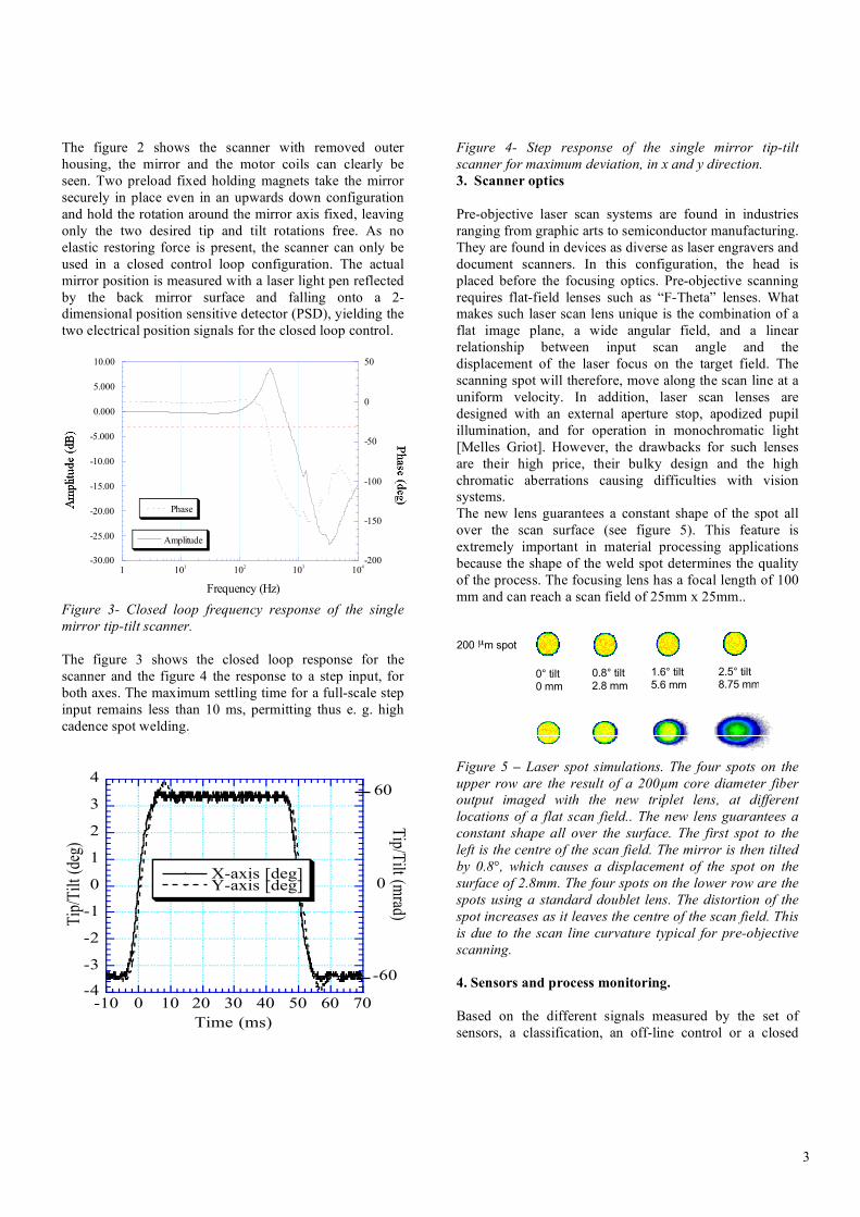
Frequency (Hz) Figure 3- Closed loop frequency response of the single mirror tip-tilt scanner. The figure 3 shows the closed loop response for the scanner and the figure 4 the response to a step input, for both axes. The maximum settling time for a full-scale step input remains less than 10 ms, permitting thus e. g. high cadence spot welding.
-4
-3
-2
-1
0
1
2
3
4
-10 0 10 20 30 40 50 60 70
X-axis [deg]Y-axis [deg]
Tip
/Til
t (d
eg)
Time (ms)
60
-60
Tip/T
ilt (mrad)
0
Figure 4- Step response of the single mirror tip-tilt scanner for maximum deviation, in x and y direction. 3. Scanner optics Pre-objective laser scan systems are found in industries ranging from graphic arts to semiconductor manufacturing. They are found in devices as diverse as laser engravers and document scanners. In this configuration, the head is placed before the focusing optics. Pre-objective scanning requires flat-field lenses such as “F-Theta” lenses. What makes such laser scan lens unique is the combination of a flat image plane, a wide angular field, and a linear relationship between input scan angle and the displacement of the laser focus on the target field. The scanning spot will therefore, move along the scan line at a uniform velocity. In addition, laser scan lenses are designed with an external aperture stop, apodized pupil illumination, and for operation in monochromatic light [Melles Griot]. However, the drawbacks for such lenses are their high price, their bulky design and the high chromatic aberrations causing difficulties with vision systems. The new lens guarantees a constant shape of the spot all over the scan surface (see figure 5). This feature is extremely important in material processing applications because the shape of the weld spot determines the quality of the process. The focusing lens has a focal length of 100 mm and can reach a scan field of 25mm x 25mm..
0° tilt0 mm
0.8° tilt2.8 mm
1.6° tilt5.6 mm
2.5° tilt8.75 mm
200 µm spot
22 mm beam
11 mm beam
0°0 mm
0.8°2.8 mm
1.6°5.6 mm
2.5°8.75 mm
Z = 91.8 mm
Z = 91.8 mm
Z = 91.65 mm
Z = 91.35 mm
Figure 5 – Laser spot simulations. The four spots on the upper row are the result of a 200µm core diameter fiber output imaged with the new triplet lens, at different locations of a flat scan field.. The new lens guarantees a constant shape all over the surface. The first spot to the left is the centre of the scan field. The mirror is then tilted by 0.8°, which causes a displacement of the spot on the surface of 2.8mm. The four spots on the lower row are the spots using a standard doublet lens. The distortion of the spot increases as it leaves the centre of the scan field. This is due to the scan line curvature typical for pre-objective scanning. 4. Sensors and process monitoring. Based on the different signals measured by the set of sensors, a classification, an off-line control or a closed
4
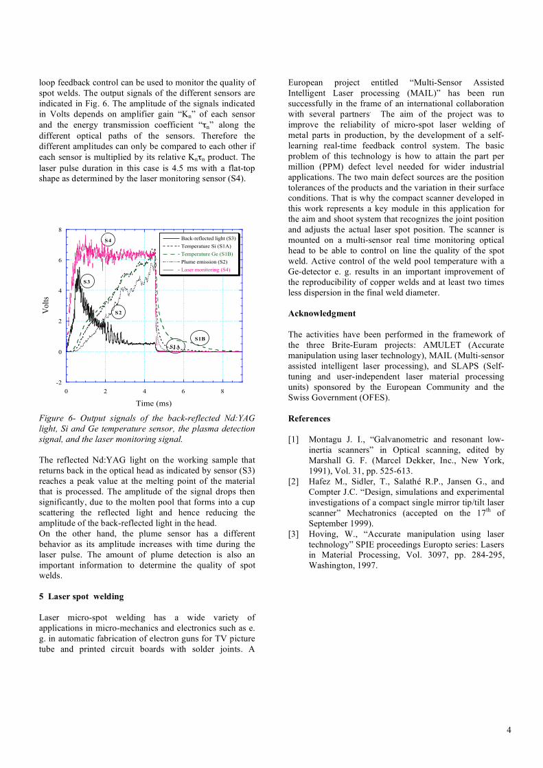
loop feedback control can be used to monitor the quality of spot welds. The output signals of the different sensors are indicated in Fig. 6. The amplitude of the signals indicated in Volts depends on amplifier gain “Kn” of each sensor and the energy transmission coefficient “τn” along the different optical paths of the sensors. Therefore the different amplitudes can only be compared to each other if each sensor is multiplied by its relative Knτn product. The laser pulse duration in this case is 4.5 ms with a flat-top shape as determined by the laser monitoring sensor (S4).
-2
0
2
4
6
8
0 2 4 6 8
Back-reflected light (S3)
Temperature Si (S1A)
Temperature Ge (S1B)
Plume emission (S2)
Laser monitoring (S4)
Vo
lts
Time (ms)
S3
S4
S1B
S2
S1A
Figure 6- Output signals of the back-reflected Nd:YAG light, Si and Ge temperature sensor, the plasma detection signal, and the laser monitoring signal. The reflected Nd:YAG light on the working sample that returns back in the optical head as indicated by sensor (S3) reaches a peak value at the melting point of the material that is processed. The amplitude of the signal drops then significantly, due to the molten pool that forms into a cup scattering the reflected light and hence reducing the amplitude of the back-reflected light in the head. On the other hand, the plume sensor has a different behavior as its amplitude increases with time during the laser pulse. The amount of plume detection is also an important information to determine the quality of spot welds. 5 Laser spot welding Laser micro-spot welding has a wide variety of applications in micro-mechanics and electronics such as e. g. in automatic fabrication of electron guns for TV picture tube and printed circuit boards with solder joints. A
European project entitled “Multi-Sensor Assisted Intelligent Laser processing (MAIL)” has been run successfully in the frame of an international collaboration with several partners. The aim of the project was to improve the reliability of micro-spot laser welding of metal parts in production, by the development of a self-learning real-time feedback control system. The basic problem of this technology is how to attain the part per million (PPM) defect level needed for wider industrial applications. The two main defect sources are the position tolerances of the products and the variation in their surface conditions. That is why the compact scanner developed in this work represents a key module in this application for the aim and shoot system that recognizes the joint position and adjusts the actual laser spot position. The scanner is mounted on a multi-sensor real time monitoring optical head to be able to control on line the quality of the spot weld. Active control of the weld pool temperature with a Ge-detector e. g. results in an important improvement of the reproducibility of copper welds and at least two times less dispersion in the final weld diameter. Acknowledgment The activities have been performed in the framework of the three Brite-Euram projects: AMULET (Accurate manipulation using laser technology), MAIL (Multi-sensor assisted intelligent laser processing), and SLAPS (Self-tuning and user-independent laser material processing units) sponsored by the European Community and the Swiss Government (OFES). References [1] Montagu J. I., “Galvanometric and resonant low-
inertia scanners” in Optical scanning, edited by Marshall G. F. (Marcel Dekker, Inc., New York, 1991), Vol. 31, pp. 525-613.
[2] Hafez M., Sidler, T., Salathé R.P., Jansen G., and Compter J.C. “Design, simulations and experimental investigations of a compact single mirror tip/tilt laser scanner” Mechatronics (accepted on the 17th of September 1999).
[3] Hoving, W., “Accurate manipulation using laser technology” SPIE proceedings Europto series: Lasers in Material Processing, Vol. 3097, pp. 284-295, Washington, 1997.