Embed Size (px)
DESCRIPTION
All about the Airbus A380
Citation preview
1
L’A380 pour Air France
2
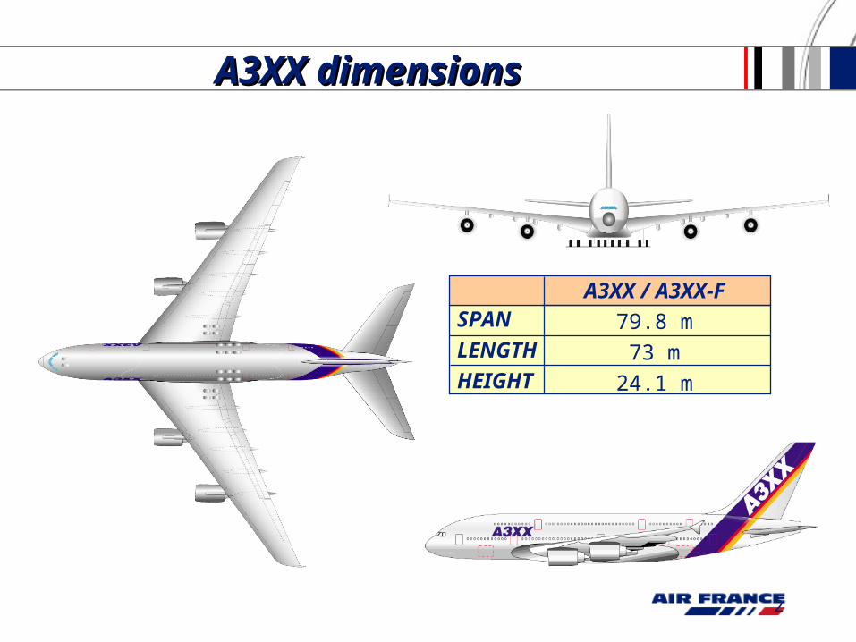
A3XX / A3XX-F
79.8 m
73 m
24.1 m
SPAN
LENGTH
HEIGHT
A3XX dimensionsA3XX dimensions
3
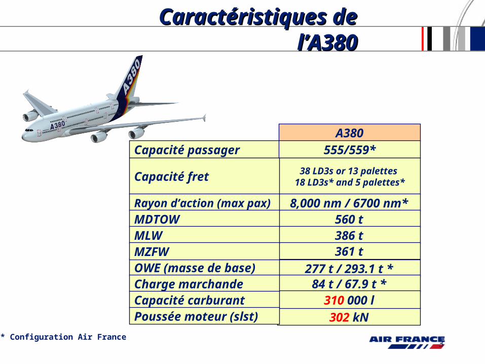
Caractéristiques de Caractéristiques de l’A380l’A380
277 t / 293.1 t *
38 LD3s or 13 palettes 18 LD3s* and 5 palettes*
8,000 nm / 6700 nm*560 t
302 kN
A380
386 t361 t
84 t / 67.9 t *310 000 l
OWE (masse de base)
Capacité fret
Rayon d’action (max pax)
MDTOWMLWMZFW
Charge marchande Capacité carburantPoussée moteur (slst)
Capacité passager
* Configuration Air France
555/559*
4
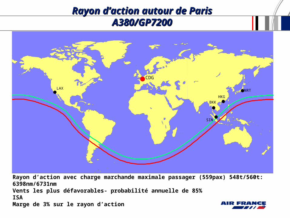
Rayon d’action autour de Rayon d’action autour de Paris A380/GP7200Paris A380/GP7200
CDG
LAX
BKK
NRT
HKG
SIN
Rayon d’action avec charge marchande maximale passager (559pax) 548t/560t: 6398nm/6731nmVents les plus défavorables- probabilité annuelle de 85%ISAMarge de 3% sur le rayon d’action
5
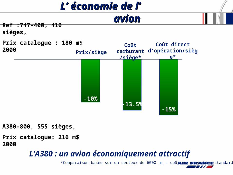
L’ économie de l’ L’ économie de l’ avionavion
Ref :747-400, 416 sièges,
Prix catalogue : 180 m$ 2000
A380-800, 555 sièges,
Prix catalogue: 216 m$ 2000
Prix/siègeCoût direct
d'opération/siège*
L’A380 : un avion économiquement attractif
-10%-13.5%
Coût carburant /siège*
-15%
*Comparaison basée sur un secteur de 6000 nm - coûts d ’opération standards Airbus
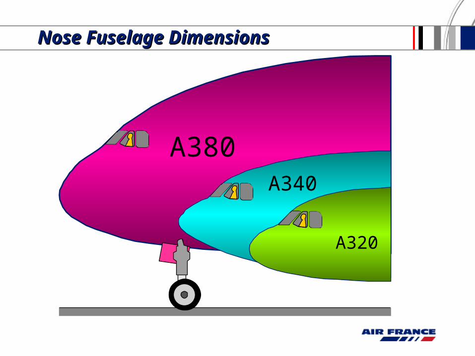
Nose Fuselage DimensionsNose Fuselage Dimensions
A380A340
A320
7
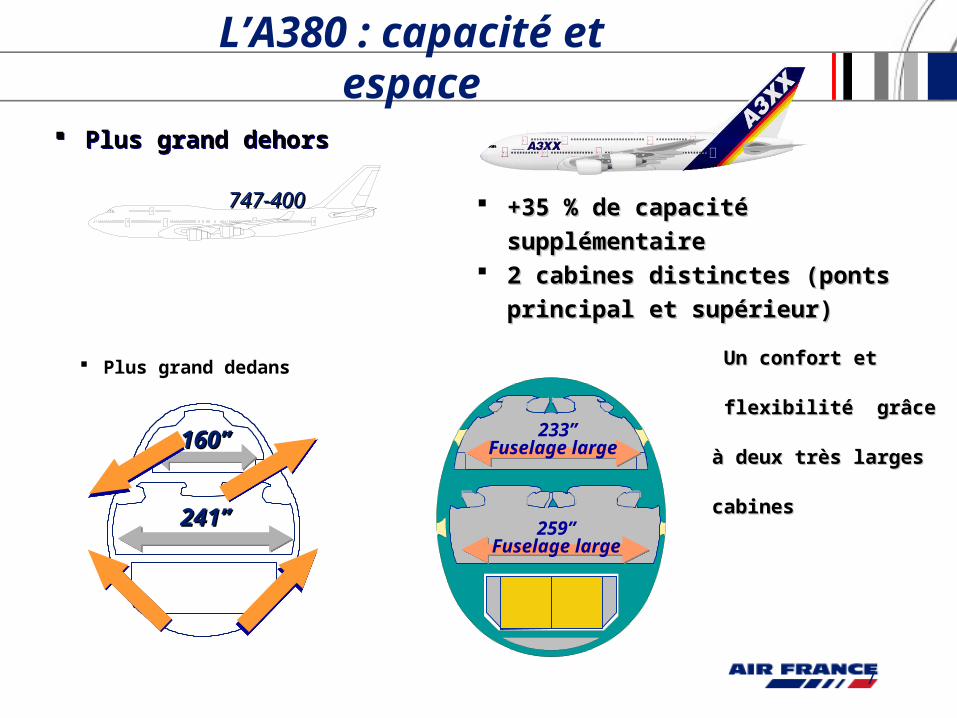
Plus grand dehors Plus grand dehors
Plus grand dedans
L’A380 : capacité et espace
747-400747-400 +35 % de capacité supplémentaire+35 % de capacité supplémentaire 2 cabines distinctes (ponts principal 2 cabines distinctes (ponts principal
et supérieur)et supérieur)
Un confort et Un confort et
flexibilité grâce à deux flexibilité grâce à deux
très larges cabinestrès larges cabines
160’’160’’
241’’241’’
233’’Fuselage large
259’’Fuselage large
8
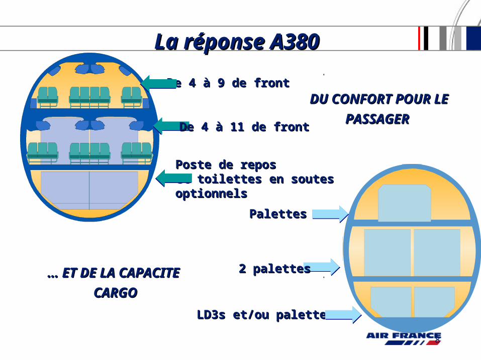
La réponse A380La réponse A380
DU CONFORT POUR DU CONFORT POUR
LE PASSAGER LE PASSAGER
… … ET DE LA CAPACITE ET DE LA CAPACITE
CARGOCARGO
De 4 à 9 de frontDe 4 à 9 de front
De 4 à 11 de frontDe 4 à 11 de front
Poste de repos Poste de repos et toilettes en soutes et toilettes en soutes optionnelsoptionnels
PalettesPalettes
2 palettes2 palettes
LD3s et/ou palettesLD3s et/ou palettes
9
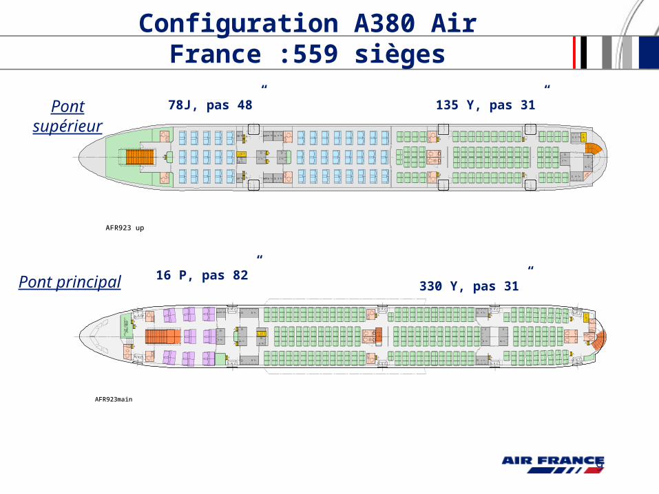
Configuration A380 Air France :559 sièges
Pont supérieur
Pont principal
16 P, pas 82”
78J, pas 48”
330 Y, pas 31”
135 Y, pas 31”
AFR923 up
AFR923main
10
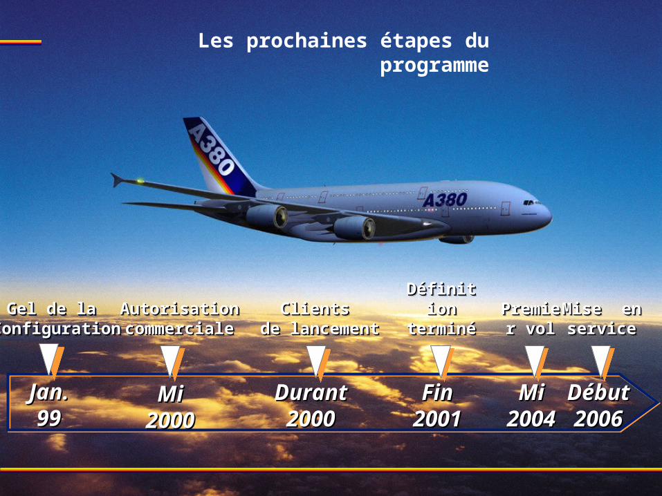
Les prochaines étapes du programme
Jan.Jan.9999
DurantDurant20002000
Gel de laGel de la ConfigurationConfiguration
Gel de laGel de la ConfigurationConfiguration
AutorisationAutorisationcommercialecommercialeAutorisationAutorisationcommercialecommerciale
Clients Clients de lancementde lancement
Clients Clients de lancementde lancement
MiMi20002000
MiMi20042004
Premier Premier volvol
Premier Premier volvol
DébutDébut20062006
Mise en Mise en serviceservice
Mise en Mise en serviceservice
FinFin20012001
Définition Définition terminéeterminée
Définition Définition terminéeterminée
11
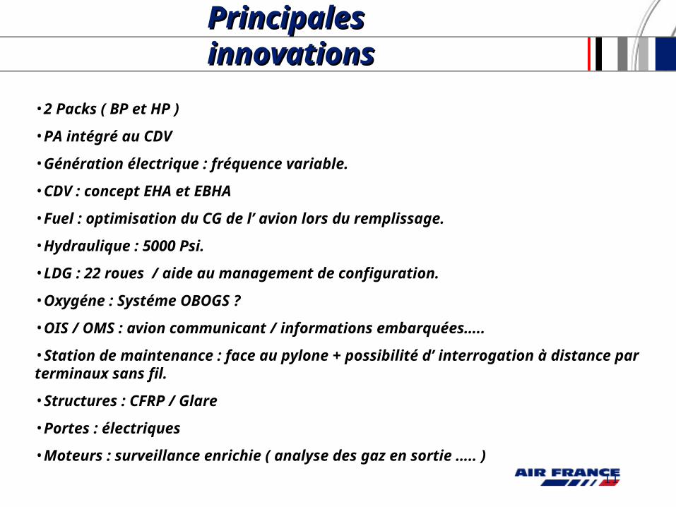
Principales Principales innovationsinnovations
•2 Packs ( BP et HP )
•PA intégré au CDV
•Génération électrique : fréquence variable.
•CDV : concept EHA et EBHA
•Fuel : optimisation du CG de l’ avion lors du remplissage.
•Hydraulique : 5000 Psi.
•LDG : 22 roues / aide au management de configuration.
•Oxygéne : Systéme OBOGS ?
•OIS / OMS : avion communicant / informations embarquées…..
•Station de maintenance : face au pylone + possibilité d’ interrogation à distance par terminaux sans fil.
•Structures : CFRP / Glare
•Portes : électriques
•Moteurs : surveillance enrichie ( analyse des gaz en sortie ….. )
12
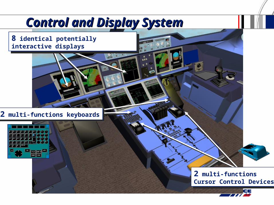
2 multi-functions keyboards2 multi-functions keyboards
8 identical potentially interactive displays8 identical potentially interactive displays
Control and Display SystemControl and Display System
2 multi-functionsCursor Control Devices
2 multi-functionsCursor Control Devices
13
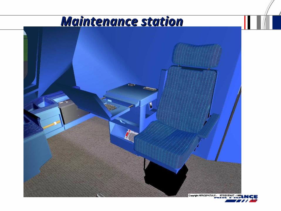
Maintenance Maintenance station station
14
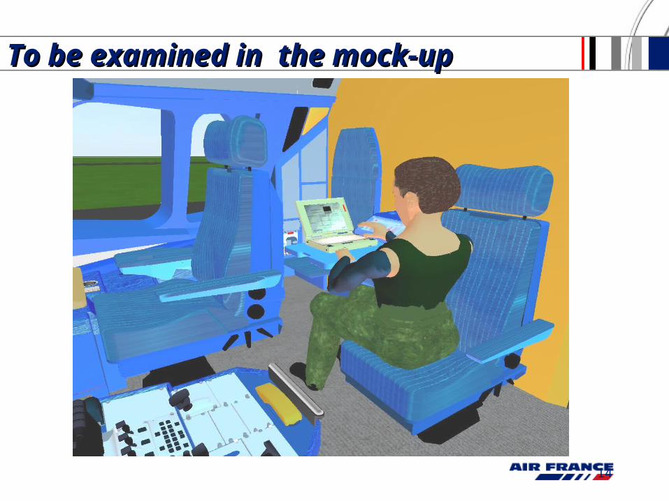
To be examined in the mock-up To be examined in the mock-up
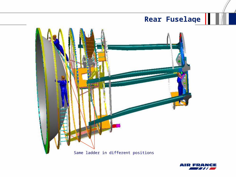
Rear Fuselage
Same ladder in different positions
16
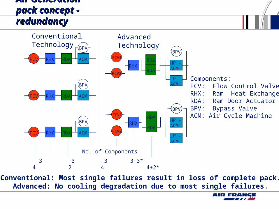
Air Air Generation Generation pack concept pack concept - redundancy- redundancy
3 3 3 3+3* 4 2 4 4+2* *for HX-mode
ConventionalTechnology
AdvancedTechnology
FCV RHX RDA ACM
BPV
FCV RHX RDA ACM
BPV
FCV RHX RDA ACM
BPV
RHXHP -ACM
BPV
LP -ACM
RHXHP -ACM
BPV
LP -ACM
No. of Components
RDA
RDA
RDA
RDA
FCV1
FCV2
FCV1
FCV2
Components:FCV: Flow Control ValveRHX: Ram Heat ExchangerRDA: Ram Door ActuatorBPV: Bypass ValveACM: Air Cycle Machine
Conventional: Most single failures result in loss of complete pack.Advanced: No cooling degradation due to most single failures.
17
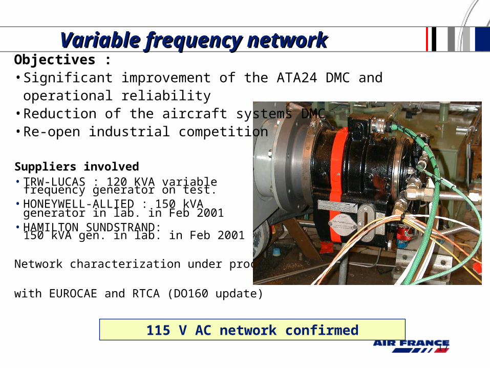
115 V AC network confirmed
Suppliers involved• TRW-LUCAS : 120 KVA variable
frequency generator on test. • HONEYWELL-ALLIED : 150 kVA
generator in lab. in Feb 2001• HAMILTON SUNDSTRAND:
150 kVA gen. in lab. in Feb 2001
Network characterization under process
with EUROCAE and RTCA (DO160 update)
Variable frequency network Variable frequency network Objectives :• Significant improvement of the ATA24 DMC and operational reliability• Reduction of the aircraft systems DMC• Re-open industrial competition
18
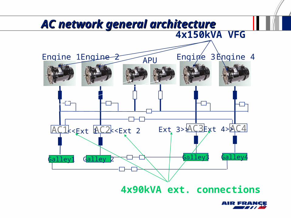
AC1 AC2 AC4AC3
Galley3Galley 2Galley1 Galley4
Engine 1 Engine 2 Engine 3 Engine 4APU
<<Ext 1 <<Ext 2 Ext 3>> Ext 4>>
AC network general AC network general architecturearchitecture
4x90kVA ext. connections
4x150kVA VFG
2x120kVACF gen
19
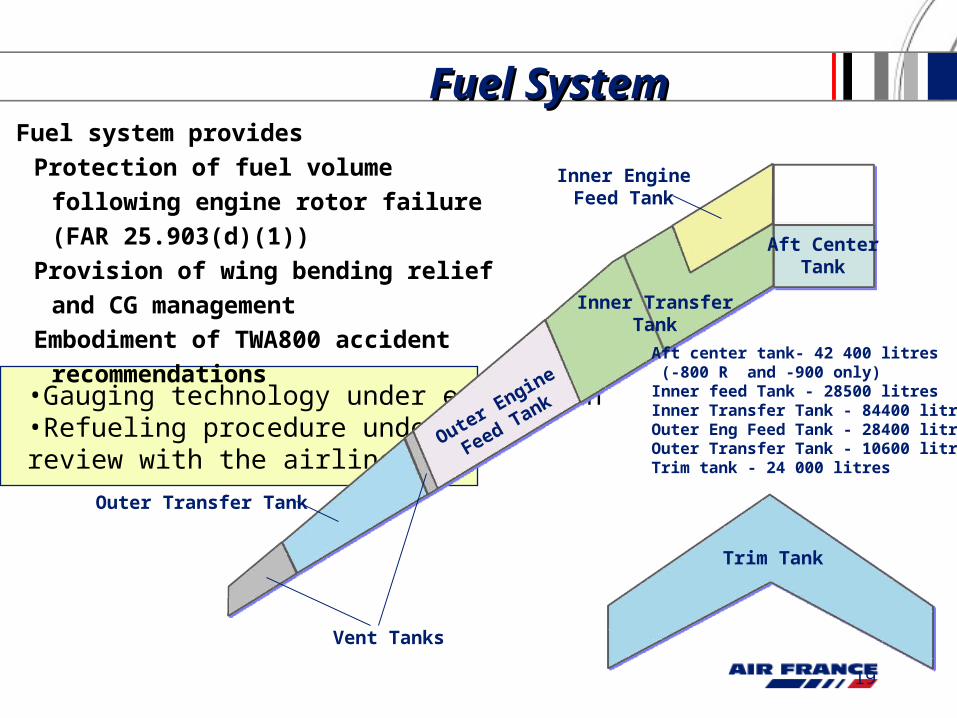
•Gauging technology under evaluation•Refueling procedure under review with the airlines
Fuel system provides
Protection of fuel volume following
engine rotor failure (FAR 25.903(d)(1))
Provision of wing bending relief and CG
management
Embodiment of TWA800 accident
recommendations
Fuel SystemFuel System
Trim Tank
Aft CenterTank
Outer Engine
Feed Tank
Outer Transfer Tank
Inner EngineFeed Tank
Vent Tanks
Inner TransferTank
Aft center tank- 42 400 litres (-800 R and -900 only)Inner feed Tank - 28500 litresInner Transfer Tank - 84400 litresOuter Eng Feed Tank - 28400 litresOuter Transfer Tank - 10600 litresTrim tank - 24 000 litres
20
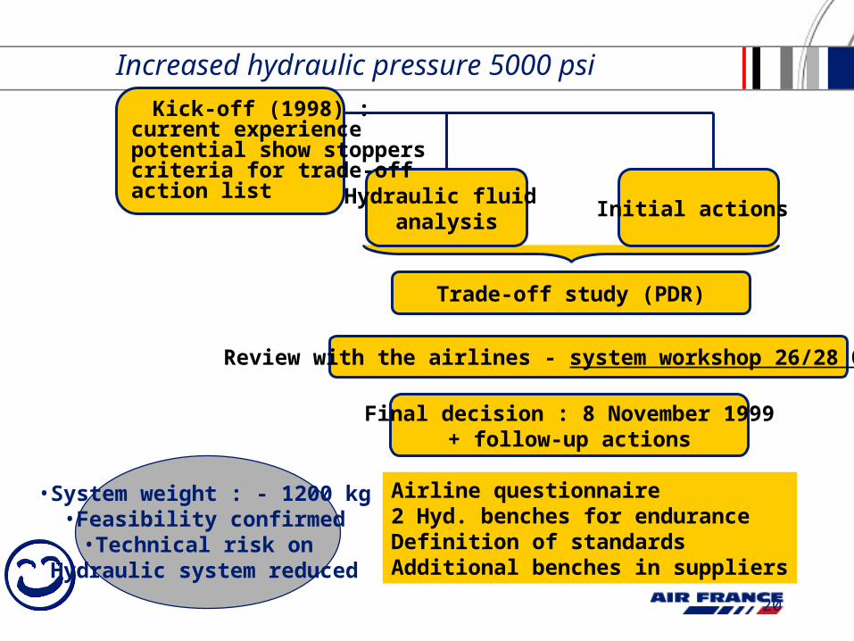
Increased hydraulic pressure 5000 psi
Trade-off study (PDR)
Hydraulic fluid analysis
Initial actions
Review with the airlines - system workshop 26/28 Oct 1999
Kick-off (1998) :current experiencepotential show stopperscriteria for trade-offaction list
Final decision : 8 November 1999+ follow-up actions
Airline questionnaire2 Hyd. benches for enduranceDefinition of standardsAdditional benches in suppliers
• System weight : - 1200 kg• Feasibility confirmed
• Technical risk on Hydraulic system reduced
21
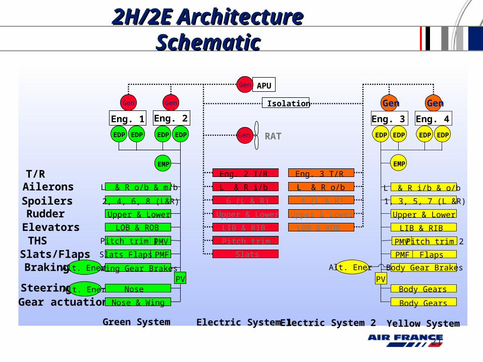
2H/2E 2H/2E Architecture Architecture SchematicSchematic
Body Gear Brakes
1, 3, 5, 7 (L &R)
Upper & Lower
LIB & RIB
Flaps
Body Gears
Body Gears
Yellow System
PMF
EDP EDP EDP EDP
Alt. Ener
Pitch trim 2PMV
EMP
Eng. 3 Eng. 4
L & R i/b & o/b
PV
Eng. 1
AileronsSpoilersRudderElevatorsTHSSlats/Flaps
Gear actuationSteering
Braking
EDP EDP
L & R o/b & m/b
2, 4, 6, 8 (L&R)
Upper & Lower
LOB & ROB
Pitch trim 1
Slats Flaps
Nose & Wing
Nose
Wing Gear Brakes
Green System
PV
PMV
PMF
EDP EDP
T/REMP
Eng. 2
Alt. Ener
Alt. Ener
Electric System 1 Electric System 2
RAT
6 (L & R)
Upper & Lower
LIB & RIB
Pitch trim
Slats
4 (L & R)
Upper & Lower
LOB & ROB
L & R i/b L & R o/b
Eng. 2 T/R Eng. 3 T/R
Gen
Gen Gen
APUGen
Isolation GenGen Gen Gen
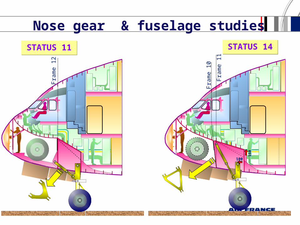
22F
ram
e 1
0
Fra
me
11
Fra
me
12
STATUS 14STATUS 14
100
15
0
STATUS 11STATUS 11
Nose gear & fuselage studies
23
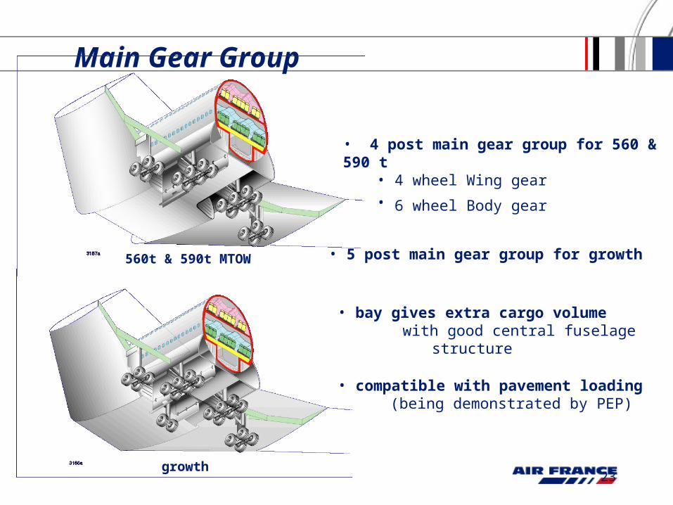
Main Gear Group
560t & 590t MTOW
growth
• 4 post main gear group for 560 & 590 t• 4 wheel Wing gear
• 6 wheel Body gear
• 5 post main gear group for growth
• bay gives extra cargo volume with good central fuselage structure
• compatible with pavement loading (being demonstrated by PEP)
24
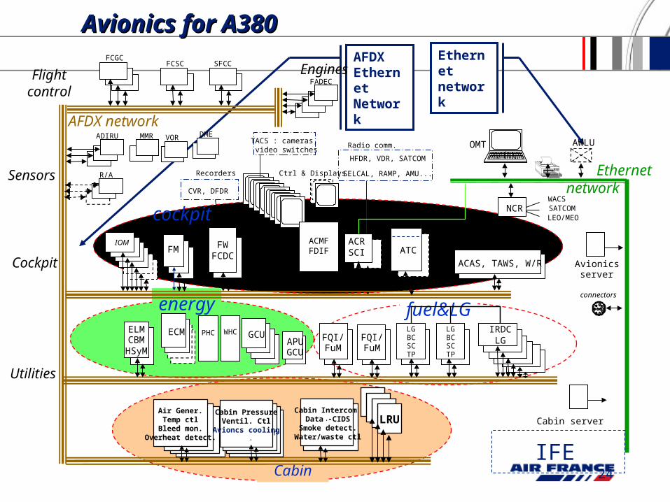
AFDX Ethernet Network
Ethernetnetwork
Avionics for A380Avionics for A380
fuel&LG
Cabin
energy
FCGCFCSC SFCC
Flightcontrol
ADIRU MMR
R/A
FADEC
ACAS, TAWS, W/R
FWFCDC
Avionicsserver
CVR, DFDR
IOM
HFDR, VDR, SATCOM
SELCAL, RAMP, AMU...
OMT AWLU
WACSSATCOMLEO/MEO
connectors
NCR
Utilities
GCUAPUGCU
ELMCBMHSyM
PHCECMFQI/FuM
FQI/FuM
LGBCSCTP
LGBCSCTP
IRDCLG
CockpitFM ATC
cockpit
Sensors
.
..Air Gene-
ration /Temp
Contr .
CabinPressure /VentalationContr .
Air Gener.Temp ctl
Bleed mon.Overheat detect.
..
Cabin PressureVentil. Ctl
Avioncs cooling.
VOR DME
Engines
Ctrl & Displays
std by
AFDX network
Ethernet network
Radio comm.
Recorders
SurveillanceACRSCI
TACS : cameras, video switches
ACMFFDIF
WHC
.
.
Cabin Intercom Data -CIDS
Smoke detect.Water/waste ctl
. .
.
LRU Cabin server
IFE
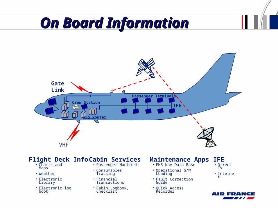
• Charts and Maps• Weather• Electronic Library• Electronic log book
IFE
Passenger Terminals
• FMS Nav Data Base• Operational S/W
Loading• Fault Correction Guide• Quick Access Recorder
FS Router
Gate Link
Crew Station
Flight Deck Info Cabin Services Maintenance Apps• Direct TV• Internet
IFE• Passenger Manifest• Consumables Tracking• Financial Transactions• Cabin Logbook, Checklist
On Board Information On Board Information
VHF
26
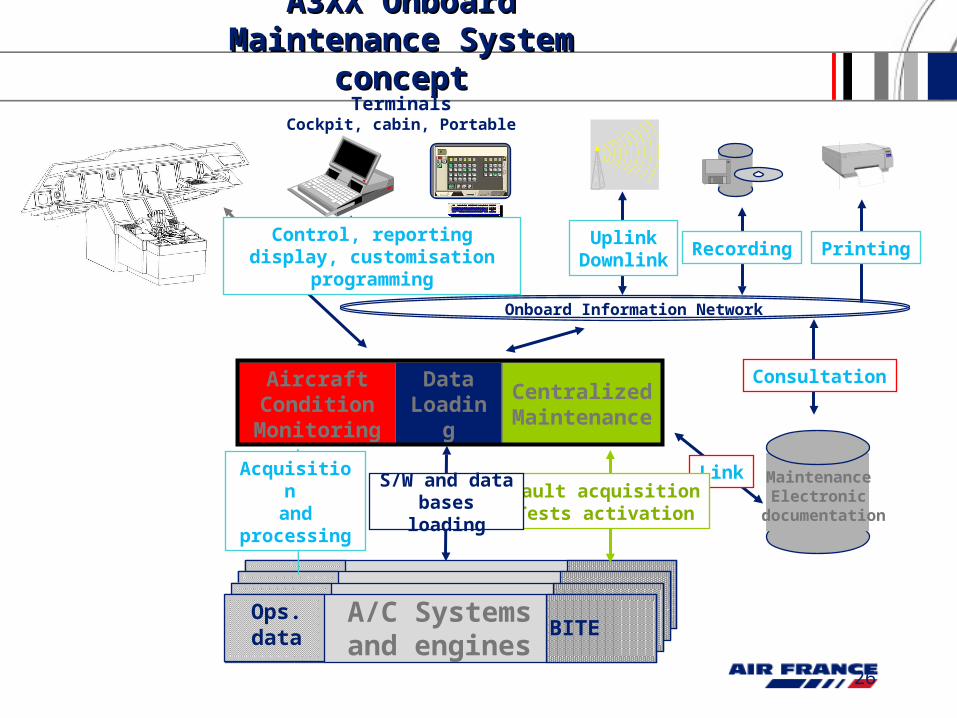
A3XX Onboard A3XX Onboard Maintenance System Maintenance System
conceptconcept
BITEA/C Systems and engines
Ops.data
Maintenance Electronic
documentation
Consultation
Link
Recording PrintingUplink
Downlink
TerminalsCockpit, cabin, Portable
Onboard Information Network
Control, reporting display, customisation programming
Centralized Maintenance
Aircraft Condition Monitoring
Data Loading
Fault acquisitionTests activation
Acquisition and processing
S/W and data bases loading
27
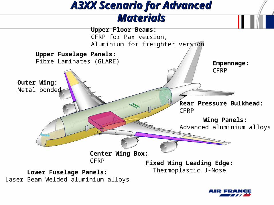
A3XX Scenario for A3XX Scenario for Advanced MaterialsAdvanced Materials
Upper Fuselage Panels:Fibre Laminates (GLARE)
Upper Floor Beams:CFRP for Pax version,Aluminium for freighter version
Center Wing Box:CFRP Fixed Wing Leading Edge:
Thermoplastic J-Nose
Rear Pressure Bulkhead:CFRP
Empennage:CFRP
Outer Wing:Metal bonded
Lower Fuselage Panels:Laser Beam Welded aluminium alloys
Wing Panels:Advanced aluminium alloys