Embed Size (px)
Citation preview
ISSN: 2455-5797 International Journal of Innovative Works in Engineering and Technology (IJIWET)
9 [Ramachandran T et al. , Vol. (3), No. (1): Feb 2017 Page]
Analysis of Power Factor Correction Techniques in Boost
Converter
T. Ramachandran Asso Prof/EEE
SCADEC,Cheranmahadevi Tirunelveli,
E. Aswini
PG Student
SCADCET,Cheranmahadevi,
Tirunelveli,
B. Ramesh Lecturer, Department of EEE
NPA Centenary Polytechnic College,
Kotagiri , The Nilgiris Dist - 643217 [email protected]
Abstract- A boost converter is a DC to DC converter with an output voltage greater than the source voltage. This project proposes a digital average current mode control method in Continuous Conduction Mode (CCM) power factor correction converter. The control technique does not estimate, but directly senses the average value of the inductor current in each switching cycle. It is implemented by means of a conventional current sensing circuit and a microcontroller. The calculation burden of the microcontroller is the same with that of conventional two loop controlled converter because the additional calculation process is not required. The Power Factor Correction (PFC) uses Average Current-Mode control. The PFC strategy uses PID controller to correct the input current shape and a fuzzy controller to control the output voltage. Since the performance of fuzzy logic controller only depends on the selection of membership function and the inference of fuzzy rules, fuzzy logic controllers have an advantage in coping with the time varying nonlinearity of switches. On the other hand, PID controller design requires an accurate mathematical model of the plant and it failed to perform satisfactorily under parameter variation, nonlinearity, load disturbance, etc. We build the model and simulate it in MATLAB. The simulation results show that the fuzzy controller for output voltage can achieve better dynamic response than its PI counterpart under larger load disturbance and plant uncertainties. The work offers a platform for digital PFC. The control method achieves lower total harmonic distortion and higher power factor than the conventional technique.
Keywords: Boost converter, current mode control, continuous conduction mode, power factor correction, PI
controller, fuzzy logic controller.
1. INTRODUCTION
A boost converter ( R. D. Middlebrook from Caltech in 1977) is a DC-to-DC power converter that steps up
voltage (while stepping down current) from its input (supply) to its output (load) [1]. It is a class of switched-
mode power supply (SMPS) containing at least two semiconductors (a diode and a transistor) and at least
one energy storage element: a capacitor, inductor, or the two in combination. To reduce voltage ripple, filters
made of capacitors (sometimes in combination with inductors) are normally added to such a converter's
output (load-side filter) and input (supply-side filter). Power for the boost converter can come from any
suitable DC sources, such as batteries, solar panels, rectifiers and DC generators. A process that changes one
DC voltage to a different DC voltage is called DC to DC conversion. A boost converter is a DC to DC
converter with an output voltage greater than the source voltage. A boost converter sometimes called step-up
converter since it "steps up" the source voltage. Switched systems such as SMPS are a challenge to design
since their models depend on whether a switch is opened or closed. Boost converter widely applicable in
battery power systems often stack cells in series to achieve higher voltage. However, sufficient stacking of
cells is not possible in many high voltage applications due to lack of space. Boost converters can increase the
voltage and reduce the number of cells. Two battery-powered applications that use boost converters are used
in hybrid electric vehicles (HEV) and lighting systems. [2] The boost converter with power factor correction
ISSN: 2455-5797 International Journal of Innovative Works in Engineering and Technology (IJIWET)
10 [Ramachandran T et al. , Vol. (3), No. (1): Feb 2017 Page]
is used to obtain the voltage output at constant voltage with continuous conduction mode. This paper
compares the improved result simulated by three different controllers in different modes. The THD and
power factor is analyzed for boost converter without controllers, voltage mode power factor control with PID
controller (James Clerk Maxwell in 1868) and fuzzy logic controller( Lotfi Zadeh, 1920) and voltage and
current mode power factor correction using PI controller.
Z. Lai, K. M. Smedley, and Y. Ma, “Time quantity one-cycle control for power-factor correctors,”
IEEE Trans. Power Electron [3] ., A time quantity one-cycle control method is proposed in this paper for
unity power-factor AC-DC power converters. Power converters controlled by this method operate at constant
switching frequency, require no current sensing, have a simple control circuit and exhibit resistive input
impedance at the AC side. A feedback loop design method is provided to minimize the current distortion
when the output voltage ripple is not negligible. Experimental results confirmed the theoretical prediction. K.
Yao, X. Ruan, X. Mao, and Z. Ye, “Variable-duty-cycle control to achieve high input power factor for DCM
PFC boost converter,” IEEE Trans. Ind. Electron [4]., A discontinuous-current-mode (DCM) boost power
factor correction (PFC) converter features zero-current turn-on for the switch, no reverse recovery in diode,
and constant-frequency operation. However, the input power factor (PF) is relatively low when the duty
cycle is constant in a half line cycle. This paper derives the expressions of the input current and PF of the
DCM boost PFC converter, and based on that, variable-duty-cycle control is proposed so as to improve the
PF to nearly unity in the whole input-voltage range. A method of fitting the duty cycle is further proposed for
simplifying the circuit implementation. J. Lazar and S. C ́ u k, “Feedback loop analysis for ac/dc rectifiers
operating in discontinuous conduction mode,” in Proc. IEEE Appl [5]. Power Electron Conf. High power
factor rectifier employing converters operating in discontinuous conduction mode (DCM) exhibit
"automatic" current shaping and use output voltage feedback to regulate the output voltage. Analysis of this
feedback control loop requires derivation of the control-to-output transfer function in the presence of the
rectified AC source voltage. In this paper, linear, line frequency averaged control-to-output transfer functions
are derived for some common DCM power converter based rectifier topologies.
2. POWER FACTOR CORRECTION TECHNIQUES
PID Controller
PID Controller This introduction will show you the characteristics of the each of proportional (P), the
integral (I), and the derivative (D) controls, and how to use them to obtain a desired response. In this tutorial,
we will consider the following unity feedback system The transfer function of the most basic form of PID
controller, as we use in ME475, is Where KP = Proportional gain, KI = Integral gain and KD
=Derivative gain.
Fuzzy Logic Controller
Fuzzy Logic Controller (FLC) is based on fuzzy logic controller and constitutes a way of converting
linguistic control strategy into an automatic by generating a rule base which controls the behavior of the
system. Fuzzy control is control method based on fuzzy logic. Fuzzy provides a remarkably simple way to
draw definite conclusions from vague ambiguous or imprecise information. It suitable for applications such
as the speed control of dc motor which is has non linearity [2, 6, 11].
FLC have some advantages compared to other classical controller such as simplicity of control, low cost
and the possibility to design without knowing the exact mathematical model of the process. Fuzzy logic
incorporates an alternative way of thinking which allows modeling complex systems using higher level of
abstraction originating from the knowledge and experience. Fuzzy logic can be described simply as “computing
words rather than numbers” or “control with sentence rather than equations.”
ISSN: 2455-5797 International Journal of Innovative Works in Engineering and Technology (IJIWET)
11 [Ramachandran T et al. , Vol. (3), No. (1): Feb 2017 Page]
The applications of fuzzy logic are usually for household appliance such as washing machine and
rice cooker. Fuzzy also been used in industrial process such as cement kilns, underground trains and robots.
Membership Function
The linguistic variables chosen for this controller are speed deviation, active power deviation and
voltage. In this, the speed deviation and active power deviation are the input linguistic variables and voltage
is the output linguistic variable. Each of the input and output fuzzy variables is assigned seven linguistic
fuzzy subsets varying from negative big (NB) to positive big (PB). Each subset is associated with a
triangular membership function to form a set of seven membership functions for each fuzzy variable.
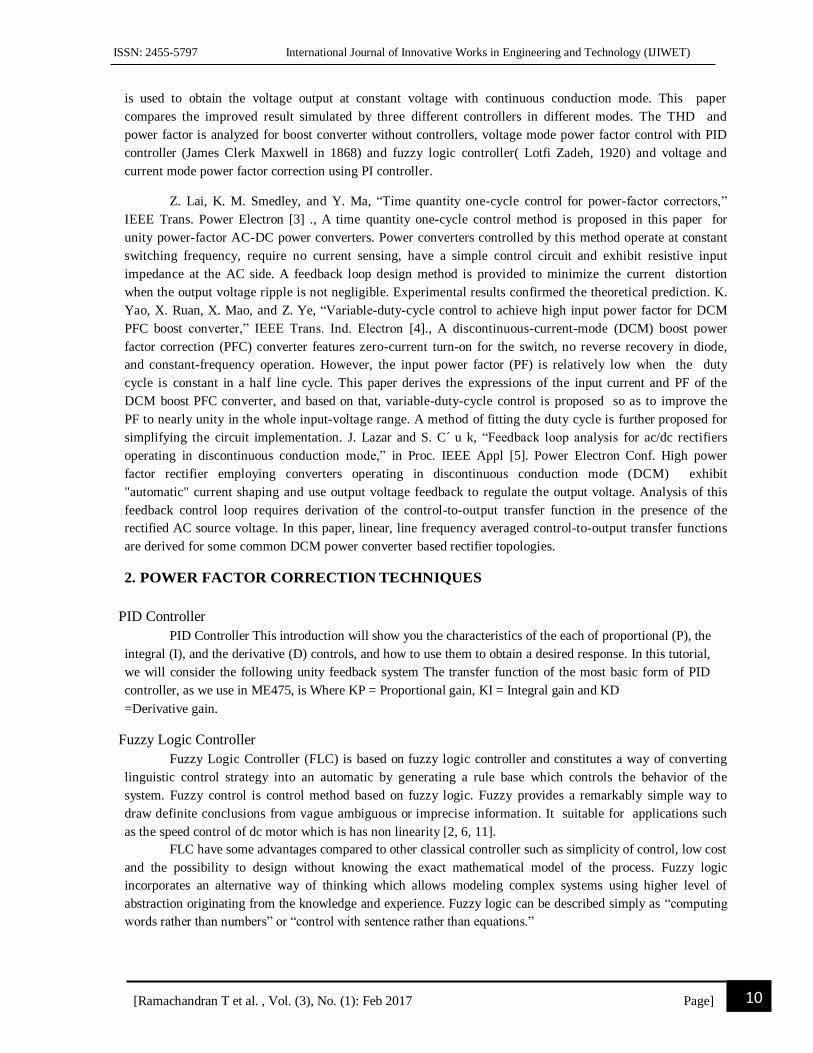
Structure of Fuzzy Logic
There are specific components characteristic of a fuzzy controller to support a design procedure.
Figure 3 shows the controller between the preprocessing block and post processing block [7, 13].
Figure 2.1: Structure of fuzzy logic controller
Fuzzy Logic Toolbox
There are five primary graphical user interface (GUI) tools for building, editing and observing fuzzy
inference systems in the toolbox:-
1. Fuzzy Inference System (FIS) editor
2. Membership Function editor
3. Rule Editor
4. Rule Viewer
5. Surface Viewer
These GUI are dynamically linked and if the changes make to the FIS to the one of the toolbox, the
effect can be seen in other GUIs. In addition to these five primary GUIs, the toolbox includes the graphical
ANFIS Editor GUI, which is used for building and analyzing Sugeno-types adaptive neural fuzzy inference
systems [8].
The advantages of the fuzzy systems are:
1. Capacity to represent inherent uncertainties of the human knowledge with linguistic variables;
2. Simple interaction of the expert of the domain with the engineer designer of the system;
3. Easy interpretation of the results, because of the natural rules representation;
4. Easy extension of the base of knowledge through the addition of new rules;
5. Robustness in relation of the possible disturbances in the system.
ISSN: 2455-5797 International Journal of Innovative Works in Engineering and Technology (IJIWET)
12 [Ramachandran T et al. , Vol. (3), No. (1): Feb 2017 Page]
3. POWER FACTOR CORRECTION IN BOOST CONVERTER
Boost Converter
It is a type of power converter in which the DC voltage obtained at the output stage is greater than that given
at the input. It can be considered as a kind of switching-mode power supply (SMPS). Although it can be
formed in different configurations, the basic structure must have at least two semiconductor switches
(generally a diode and a transistor) and one energy storing element must be used.
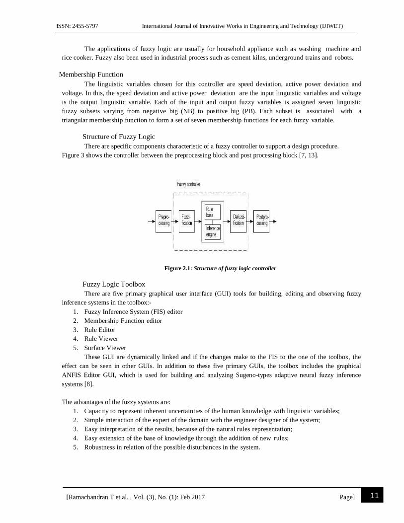
Operating Principle The inductor has this peculiar property to resist any change of current in them and that serves as the
main principle which drives a boost converter. The inductor acts like a load (like resistor) when it is being
charged and acts as a source of energy (like battery) when it is discharged. The rate of change of current
decides the voltage that is built up in the inductor while it is being discharged. The original charging voltage
is not responsible for this and hence it allows different input and output voltages[1, 9].
Figure. 3.1: Boost converter schematic
The Boost converter assumes two distinct states
1. The On-state, in which the switch S in Fig 4.1 is closed, and then there is a constant increase in the inductor
current.
2. The Off-state, in which the switch S is made open and the inductor current now flows through the diode D,
the load R and the capacitor C. In this state, the energy that has been accumulated in the inductor gets
transferred to the capacitor.
3. The input current and the inductor current are the same. Hence as one can see clearly that current in a boost
converter is continuous type and hence the design of input filter is somewhat relaxed or it is of lower value.
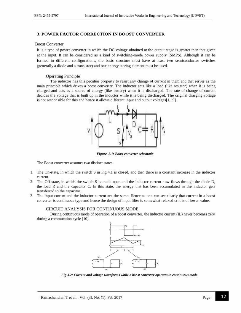
CIRCUIT ANALYSIS FOR CONTINUOUS MODE
During continuous mode of operation of a boost converter, the inductor current (IL) never becomes zero
during a commutation cycle [10].
Fig 3.2: Current and voltage waveforms while a boost converter operates in continuous mode.

ISSN: 2455-5797 International Journal of Innovative Works in Engineering and Technology (IJIWET)
13 [Ramachandran T et al. , Vol. (3), No. (1): Feb 2017 Page]
The switch S is closed to start the On-state. This makes the input voltage (VL) appear across the
inductor, and that causes change in inductor current (IL) during a finite time period (t) which is given by the
formula:
Where D is known as the duty cycle i.e. the ratio of time period for which the switch is On and the
total commutating time period T. Therefore D has a value between 0 ( that indicates S is never on) and 1 (
that indicates S is always on).
If voltage drop in the diode is neglected or assumed to be zero, and the capacitor is taken to be large
enough for maintaining a constant voltage, the equation of IL is given by:
During the time period for which the converter remains in Off state, the change in IL is given by
As we consider that the converter operates in steady-state conditions, the amount of energy stored in
each of its components has to be the same at the beginning and at the end of a commutation cycle.
Therefore, the inductor current has to be the same at the beginning and the end of the commutation
cycle. This can be written as
Substituting
This can be written as:
which in turns reveals the duty cycle to be
From the above expression it is observable that the output voltage is always greater than the input
voltage (as D is a number between 0 and 1), and that it increases as D increases. Theoretically it should approach
infinity as D approaches 1. For this reason boost converter is also known as step-up converter.
The Active PFC method proposed in this thesis deals with the continuous mode of operation for its
simplicity and easy design process.
4. PROPOSED SYSTEM
The power circuit is a dc-dc boost converter. The command circuit is the one described in which the analog
controller was replaced with a Fuzzy one. The output of the Fuzzy controller is Vc. Fig.2 contains the wave
shapes that show command principles. In average current control method, an input voltage sensing required
ISSN: 2455-5797 International Journal of Innovative Works in Engineering and Technology (IJIWET)
14 [Ramachandran T et al. , Vol. (3), No. (1): Feb 2017 Page]
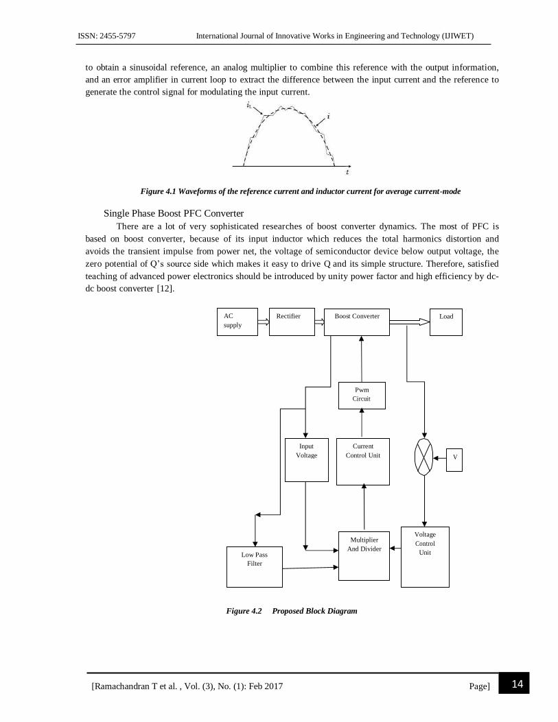
to obtain a sinusoidal reference, an analog multiplier to combine this reference with the output information,
and an error amplifier in current loop to extract the difference between the input current and the reference to
generate the control signal for modulating the input current.
Figure 4.1 Waveforms of the reference current and inductor current for average current-mode
Single Phase Boost PFC Converter
There are a lot of very sophisticated researches of boost converter dynamics. The most of PFC is
based on boost converter, because of its input inductor which reduces the total harmonics distortion and
avoids the transient impulse from power net, the voltage of semiconductor device below output voltage, the
zero potential of Q’s source side which makes it easy to drive Q and its simple structure. Therefore, satisfied
teaching of advanced power electronics should be introduced by unity power factor and high efficiency by dc-
dc boost converter [12].
Figure 4.2 Proposed Block Diagram
Input
Voltage
Current
Control Unit
Low Pass
Filter
Multiplier
And Divider
Voltage
Control
Unit
V
Pwm
Circuit
Load Boost Converter Rectifier AC
supply
ISSN: 2455-5797 International Journal of Innovative Works in Engineering and Technology (IJIWET)
15 [Ramachandran T et al. , Vol. (3), No. (1): Feb 2017 Page]
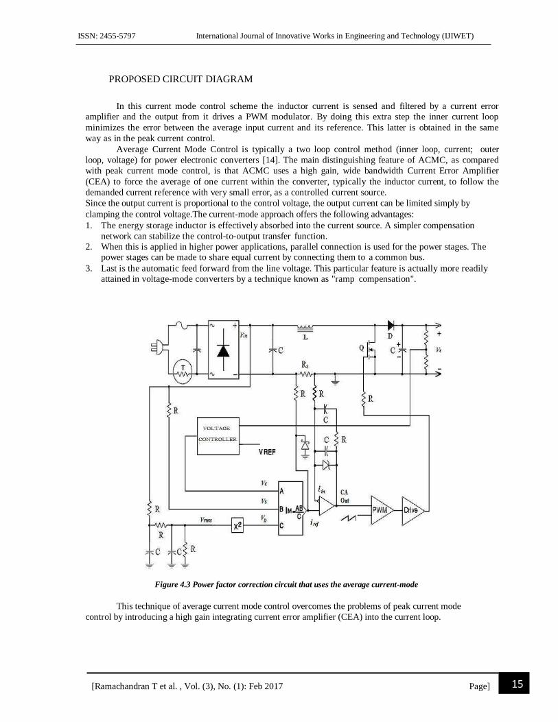
PROPOSED CIRCUIT DIAGRAM
In this current mode control scheme the inductor current is sensed and filtered by a current error
amplifier and the output from it drives a PWM modulator. By doing this extra step the inner current loop
minimizes the error between the average input current and its reference. This latter is obtained in the same
way as in the peak current control.
Average Current Mode Control is typically a two loop control method (inner loop, current; outer
loop, voltage) for power electronic converters [14]. The main distinguishing feature of ACMC, as compared
with peak current mode control, is that ACMC uses a high gain, wide bandwidth Current Error Amplifier
(CEA) to force the average of one current within the converter, typically the inductor current, to follow the
demanded current reference with very small error, as a controlled current source.
Since the output current is proportional to the control voltage, the output current can be limited simply by
clamping the control voltage.The current-mode approach offers the following advantages:
1. The energy storage inductor is effectively absorbed into the current source. A simpler compensation
network can stabilize the control-to-output transfer function.
2. When this is applied in higher power applications, parallel connection is used for the power stages. The
power stages can be made to share equal current by connecting them to a common bus.
3. Last is the automatic feed forward from the line voltage. This particular feature is actually more readily
attained in voltage-mode converters by a technique known as "ramp compensation".
Figure 4.3 Power factor correction circuit that uses the average current-mode
This technique of average current mode control overcomes the problems of peak current mode
control by introducing a high gain integrating current error amplifier (CEA) into the current loop.
ISSN: 2455-5797 International Journal of Innovative Works in Engineering and Technology (IJIWET)
16 [Ramachandran T et al. , Vol. (3), No. (1): Feb 2017 Page]
5. SOFTWARE IMPLEMENTATION
Simulations are performed by MATLAB to verify the proposed PFC control algorithm. Under the
parameters of input voltage Vl=220V(rms),output voltage Vout=400V, inductor value L=800μH,capacitor
value 1700μF one traditional PI controller for voltage loop is designed to compare with the fuzzy controller
in this paper both at 2kVA level and 500VA level. They both stable at 2kVA level. When load level changed
from 2kVA to 500VA, system with PI control exhibits a larger overshoot(25%) and longer ringing .The
current loop of PI control also obtains a high steady performance and the inductor current, rectifier voltage
and output voltage wave in steady state [15].
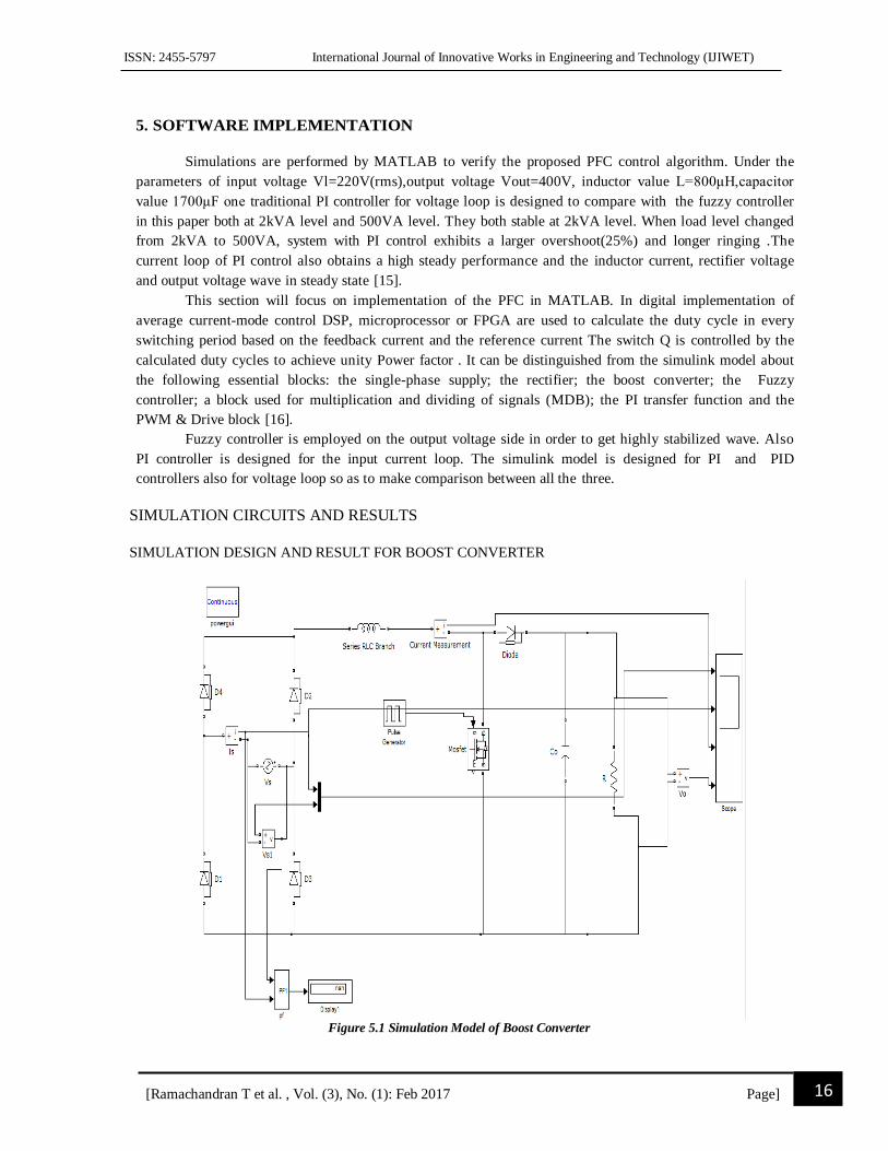
This section will focus on implementation of the PFC in MATLAB. In digital implementation of
average current-mode control DSP, microprocessor or FPGA are used to calculate the duty cycle in every
switching period based on the feedback current and the reference current The switch Q is controlled by the
calculated duty cycles to achieve unity Power factor . It can be distinguished from the simulink model about
the following essential blocks: the single-phase supply; the rectifier; the boost converter; the Fuzzy
controller; a block used for multiplication and dividing of signals (MDB); the PI transfer function and the
PWM & Drive block [16].
Fuzzy controller is employed on the output voltage side in order to get highly stabilized wave. Also
PI controller is designed for the input current loop. The simulink model is designed for PI and PID
controllers also for voltage loop so as to make comparison between all the three.
SIMULATION CIRCUITS AND RESULTS
SIMULATION DESIGN AND RESULT FOR BOOST CONVERTER
Figure 5.1 Simulation Model of Boost Converter
ISSN: 2455-5797 International Journal of Innovative Works in Engineering and Technology (IJIWET)
17 [Ramachandran T et al. , Vol. (3), No. (1): Feb 2017 Page]
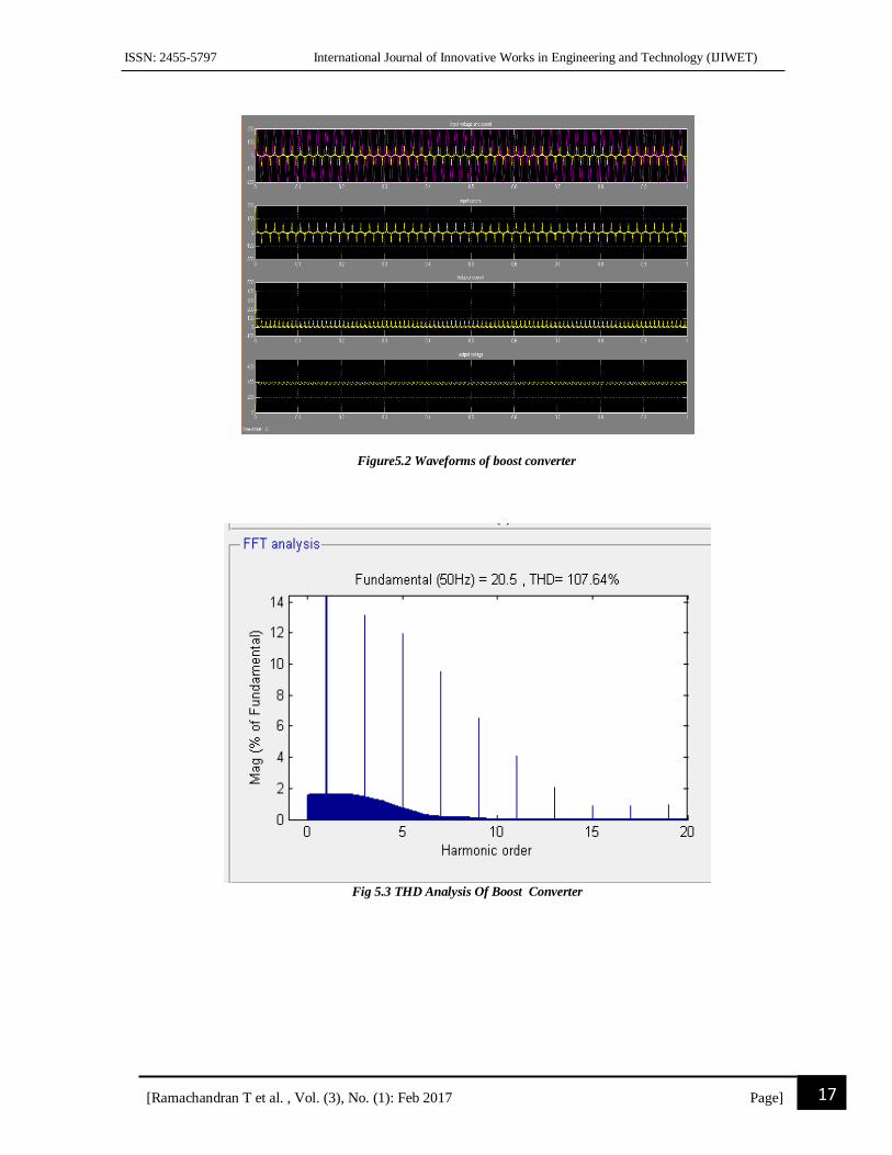
Figure5.2 Waveforms of boost converter
Fig 5.3 THD Analysis Of Boost Converter
ISSN: 2455-5797 International Journal of Innovative Works in Engineering and Technology (IJIWET)
18 [Ramachandran T et al. , Vol. (3), No. (1): Feb 2017 Page]
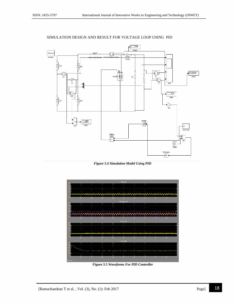
SIMULATION DESIGN AND RESULT FOR VOLTAGE LOOP USING PID
Figure 5.4 Simulation Model Using PID
Figure 5.5 Waveforms For PID Controller
ISSN: 2455-5797 International Journal of Innovative Works in Engineering and Technology (IJIWET)
19 [Ramachandran T et al. , Vol. (3), No. (1): Feb 2017 Page]
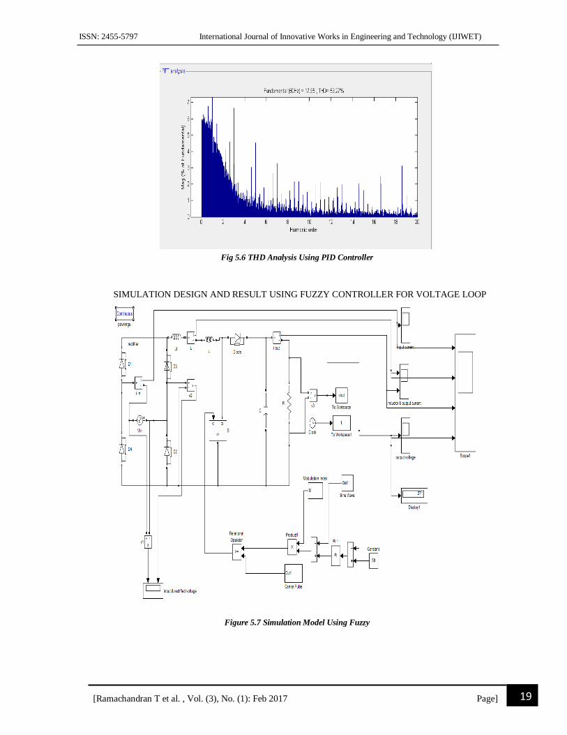
Fig 5.6 THD Analysis Using PID Controller
SIMULATION DESIGN AND RESULT USING FUZZY CONTROLLER FOR VOLTAGE LOOP
Figure 5.7 Simulation Model Using Fuzzy
ISSN: 2455-5797 International Journal of Innovative Works in Engineering and Technology (IJIWET)
20 [Ramachandran T et al. , Vol. (3), No. (1): Feb 2017 Page]
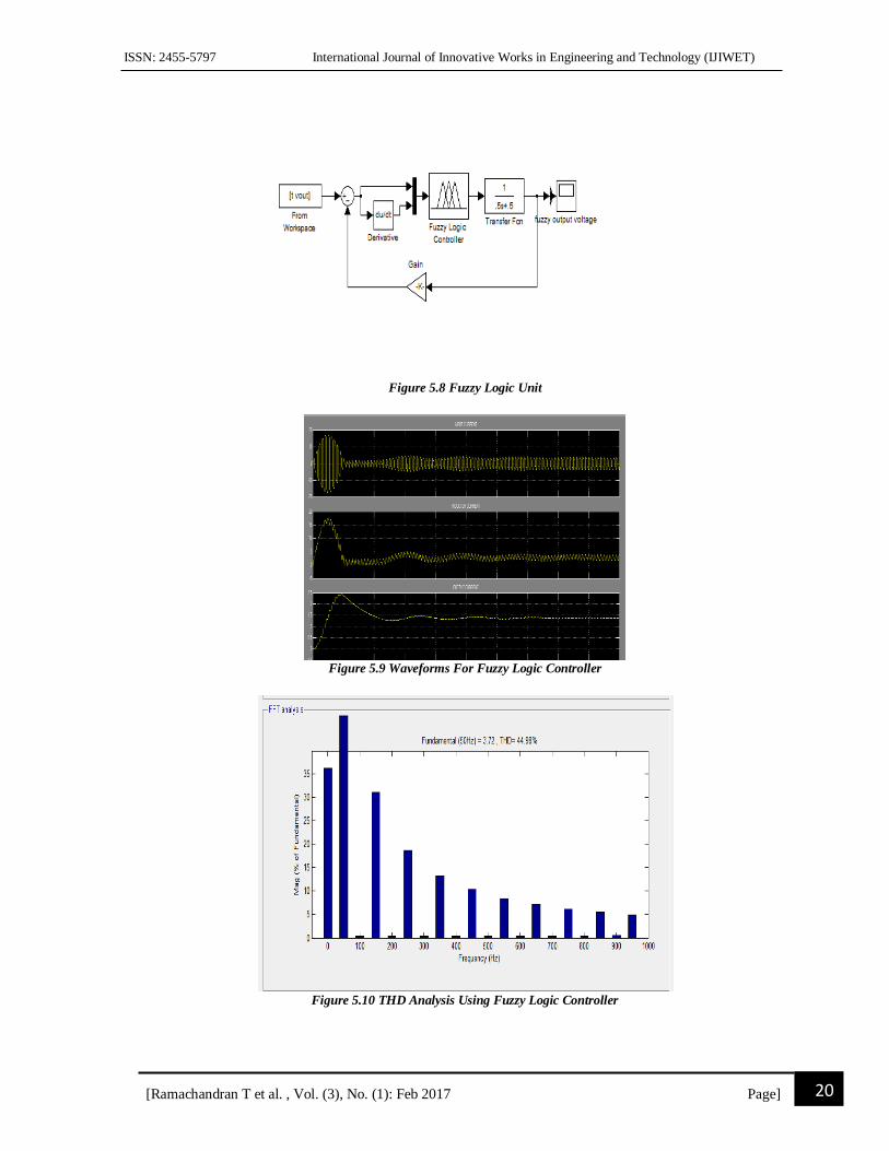
Figure 5.8 Fuzzy Logic Unit
Figure 5.9 Waveforms For Fuzzy Logic Controller
Figure 5.10 THD Analysis Using Fuzzy Logic Controller
ISSN: 2455-5797 International Journal of Innovative Works in Engineering and Technology (IJIWET)
21 [Ramachandran T et al. , Vol. (3), No. (1): Feb 2017 Page]
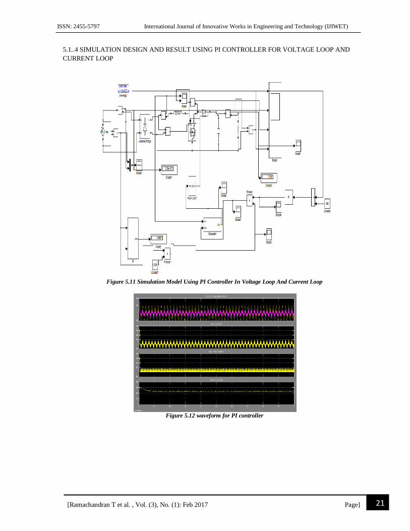
5.1..4 SIMULATION DESIGN AND RESULT USING PI CONTROLLER FOR VOLTAGE LOOP AND
CURRENT LOOP
Figure 5.11 Simulation Model Using PI Controller In Voltage Loop And Current Loop
Figure 5.12 waveform for PI controller
ISSN: 2455-5797 International Journal of Innovative Works in Engineering and Technology (IJIWET)
22 [Ramachandran T et al. , Vol. (3), No. (1): Feb 2017 Page]
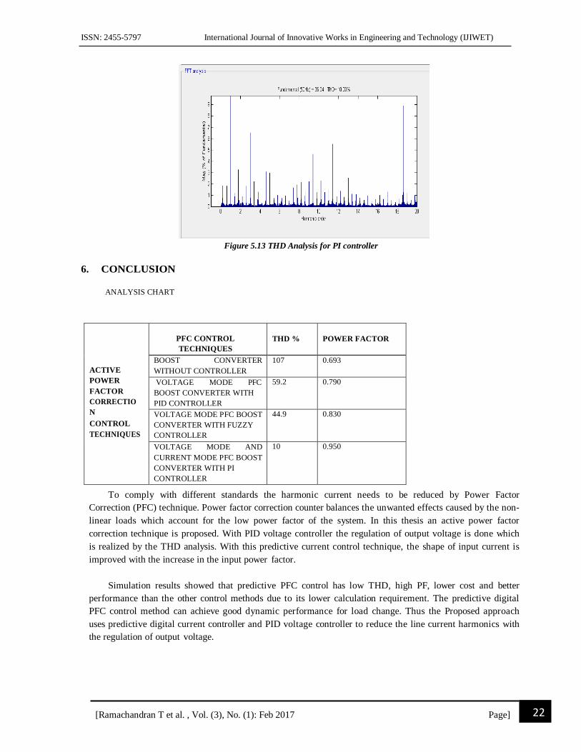
Figure 5.13 THD Analysis for PI controller
6. CONCLUSION
ANALYSIS CHART
ACTIVE
POWER
FACTOR
CORRECTIO
N
CONTROL
TECHNIQUES
PFC CONTROL
TECHNIQUES
THD %
POWER FACTOR
BOOST CONVERTER
WITHOUT CONTROLLER
107 0.693
VOLTAGE MODE PFC
BOOST CONVERTER WITH
PID CONTROLLER
59.2 0.790
VOLTAGE MODE PFC BOOST
CONVERTER WITH FUZZY
CONTROLLER
44.9 0.830
VOLTAGE MODE AND
CURRENT MODE PFC BOOST
CONVERTER WITH PI
CONTROLLER
10 0.950
To comply with different standards the harmonic current needs to be reduced by Power Factor
Correction (PFC) technique. Power factor correction counter balances the unwanted effects caused by the non-
linear loads which account for the low power factor of the system. In this thesis an active power factor
correction technique is proposed. With PID voltage controller the regulation of output voltage is done which
is realized by the THD analysis. With this predictive current control technique, the shape of input current is
improved with the increase in the input power factor.
Simulation results showed that predictive PFC control has low THD, high PF, lower cost and better
performance than the other control methods due to its lower calculation requirement. The predictive digital
PFC control method can achieve good dynamic performance for load change. Thus the Proposed approach
uses predictive digital current controller and PID voltage controller to reduce the line current harmonics with
the regulation of output voltage.

ISSN: 2455-5797 International Journal of Innovative Works in Engineering and Technology (IJIWET)
23 [Ramachandran T et al. , Vol. (3), No. (1): Feb 2017 Page]
REFERENCES
1. N. Mohan, T.M. Underland, W.P. Robbins, "Power Electronics: Converters, Applications and design, Third Edition", John
Wiley, 2002
2. P. Mattavelli, L. Rossetto, G. Spiazzi, P. Tenti. "General Purpose Fuzzy Controller for DC/DC Converters. IEEE Transaction on
Power Electronics. Vol.12 pp. 79-86. Jan - 1997
3. Z. Lai, K. M. Smedley, and Y. Ma, “Time quantity one-cycle control for power-factor correctors,” IEEE Trans. Power Electron.,
vol. 12, no. 2 pp. 369–375, Mar. 1997.
4. K. Yao, X. Ruan, X. Mao, and Z. Ye, “Variable-duty-cycle control to achieve high input power factor for DCM PFC boost
converter,” IEEE Trans. Ind. Electron., vol. 58, no. 5, pp. 1856–1865, May 2011.
5. J. Lazar and S. C´ uk, “Feedback loop analysis for ac/dc rectifiers operating in discontinuous conduction mode,” in Proc. IEEE
Appl. Power Electron.Conf., 1996, pp. 797–806.
6. V. Vorp´erian, “Simplified analysis of PWM converters using the model of the PWM switch: Parts I and II,” IEEE Trans. Aerosp.
Electron. Syst.,vol. 26, no. 2, pp. 490–496, Mar. 1990.
7. R. W. Erickson and D. Maksimovi´c, Fundamentals of Power Electronics,2nd ed. Boston, MA: Kluwer, 2001, pp. 420–427.
8. C. C. Lee, “Fuzzy logic in control systems: Fuzzy logic controller—Part I,” IEEE Trans. Syst. Man Cybern., vol. 20, pp. 404–418,
Mar./Apr. 1990.
9. Y. S.Kung and C. M. Liaw, “A fuzzy controller improving a linear model following controller for motor drives,” IEEE Trans.
Fuzzy Syst., vol. 2, pp. 194–202, Aug. 1994.
10. C. M. Liaw and S. Y. Cheng, “Fuzzy two-degrees-offreedom speed controller for motor drives,” IEEE Trans. Ind. Electron., vol.
42, pp. 209–216, Apr. 1995.
11. A. Rubaai, D. Ricketts, and M. D. Kankam, “Experimental verification of a hybrid fuzzy control strategy for a highperformance
brushless DC drive system,” IEEE Trans. Ind. Applicat., vol. 37, pp. 503–512, Mar./Apr. 2001.
12. B. R. Lin, “Analysis of fuzzy control method applied to DC-DC converter control,” in Proc. IEEE Applied Power Electronics
Conf. Expo, 1993, pp. 22–28.
13. Y.Qin, S.S.Du,“Fuzzy logic and digital PI control of single phase power factor pre-regulator for an on-line UP A comparative
study”. IEEE International Conference on Industrial Technology, 1996.
14. Philip C Todd. UC3854 Controlled. Power Factor Correction Circuit Design[J]. Unitrode IC Product & Applications Handbook
1995-1996,1995, pp. 303-322.
15. E.Toribio, A. El Aroudi, G. Olivar, L. Benadero, '"Numerical and experimental study of the region of periodone operation of a
pwm boost converter," IEEE Truns. Power Electron., vol. 15,no.6, pp.1163-1171,Nov. 2000.
16. A. El Amudi, R. Leyva, "Quasi-periodic route to chaos in a pwm voltage-controlled dc-dc boost converter," IEEE Tram Circuits
Syst. I, Vo1.48, 110.8, pp. 967-978, Aug. 2001.