Embed Size (px)
Citation preview
8/9/2019 AR-M318 SM
http://slidepdf.com/reader/full/ar-m318-sm 1/159
Parts marked with “ ” are important for maintaining the safety of the set. Be sure to replace these parts withspecified ones for maintaining the safety and performance of the set.
This document has been published to be usedfor after sales service only.The contents are subject to change without notice.
SERVICE MANUAL
CONTENTS
CODE: 00ZARM318/S1E
DIGITAL MULTIFUNCTIONAL
SYSTEMAR-M256/M257AR-M258/M316AR-M317/M318
MODEL AR-5625/5631AR-M257/M317
AR-M256/M258AR-M316/M318AR-5625/M5631
[1] NOTE FOR SERVICING . . . . . . . . . . . . . . . . . . . . . . . . . . . . . . . . 1-1
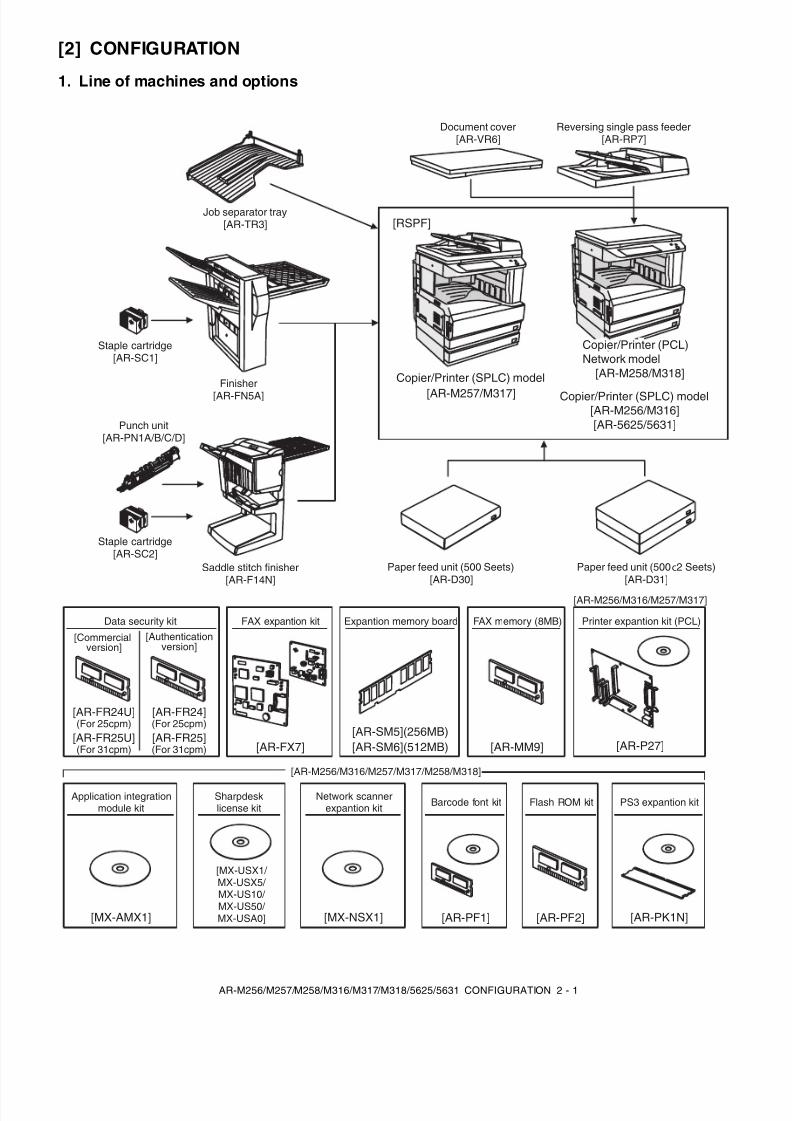
[2] CONFIGURATION . . . . . . . . . . . . . . . . . . . . . . . . . . . . . . . . . . . . . 2-1
[3] SPECIFICATIONS . . . . . . . . . . . . . . . . . . . . . . . . . . . . . . . . . . . . . 3-1
[4] CONSUMABLE PARTS . . . . . . . . . . . . . . . . . . . . . . . . . . . . . . . . . 4-1
[5] UNPACKING AND INSTALLATION . . . . . . . . . . . . . . . . . . . . . . . . 5-1
[6] EXTERNAL VIEW AND INTERNAL STRUCTURE . . . . . . . . . . . . 6-1
[7] ADJUSTMENTS, SETTING . . . . . . . . . . . . . . . . . . . . . . . . . . . . . . 7-1
[8] SIMULATION . . . . . . . . . . . . . . . . . . . . . . . . . . . . . . . . . . . . . . . . . 8-1
[9] TROUBLE CODE LIST . . . . . . . . . . . . . . . . . . . . . . . . . . . . . . . . . 9-1
[10] DISASSEMBLY, ASSEMBLY AND MAINTENANCE . . . . . . . . . . 10-1
[11] OTHERS . . . . . . . . . . . . . . . . . . . . . . . . . . . . . . . . . . . . . . . . . . . 11-1
[12] ELECTRICAL SECTION . . . . . . . . . . . . . . . . . . . . . . . . . . . . . . . 12-1
8/9/2019 AR-M318 SM
http://slidepdf.com/reader/full/ar-m318-sm 2/159
CONTENTS
[1] NOTE FOR SERVICING1. Warning for servicing. . . . . . . . . . . . . . . . . . . . . . . . . . . . . 1-12. Precautions for servicing . . . . . . . . . . . . . . . . . . . . . . . . . . 1-13. Note for installing site . . . . . . . . . . . . . . . . . . . . . . . . . . . . 1-1
[2] CONFIGURATION1. Line of machines and options . . . . . . . . . . . . . . . . . . . . . . 2-12. Combination of options list. . . . . . . . . . . . . . . . . . . . . . . . . 2-2
[3] SPECIFICATIONS
1. Basic specifications . . . . . . . . . . . . . . . . . . . . . . . . . . . . . . 3-12. Operation specifications . . . . . . . . . . . . . . . . . . . . . . . . . . 3-1A. Common operation . . . . . . . . . . . . . . . . . . . . . . . . . . . . 3-1B. Copy mode . . . . . . . . . . . . . . . . . . . . . . . . . . . . . . . . . . 3-1
3. Engine specifications. . . . . . . . . . . . . . . . . . . . . . . . . . . . . 3-2A. Operation and display section . . . . . . . . . . . . . . . . . . . . 3-2B. Paper feed, transport, paper exit section . . . . . . . . . . . 3-2C. Optical (Image scanning) section . . . . . . . . . . . . . . . . . 3-3D. Scanner (exposure) section . . . . . . . . . . . . . . . . . . . . . 3-3E. Image process section . . . . . . . . . . . . . . . . . . . . . . . . . 3-3F. Fusing . . . . . . . . . . . . . . . . . . . . . . . . . . . . . . . . . . . . . . 3-4G. Drive . . . . . . . . . . . . . . . . . . . . . . . . . . . . . . . . . . . . . . . 3-4
4. Additional functions, copy functions,and expanded functions. . . . . . . . . . . . . . . . . . . . . . . . . . . 3-4
5. Safety and environmental protection standards . . . . . . . . 3-4
6. Environment conditions . . . . . . . . . . . . . . . . . . . . . . . . . . . 3-57. IMC board functions. . . . . . . . . . . . . . . . . . . . . . . . . . . . . . 3-58. Printer function
(AR-M256/ M257/ M316/ M317/ 5625/ 5631) . . . . . . . . . . 3-6A. “Sharp Printer Language with Compression (SPLC)”
Printer function . . . . . . . . . . . . . . . . . . . . . . . . . . . . . . . 3-6B. Printer driver specification. . . . . . . . . . . . . . . . . . . . . . . 3-6C. Interface . . . . . . . . . . . . . . . . . . . . . . . . . . . . . . . . . . . . 3-8D. System outline. . . . . . . . . . . . . . . . . . . . . . . . . . . . . . . . 3-8
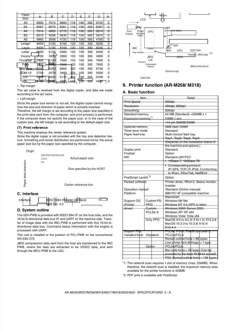
9. Printer function (AR-M258/ M318) . . . . . . . . . . . . . . . . . . . 3-8A. Basic function . . . . . . . . . . . . . . . . . . . . . . . . . . . . . . . . 3-8
[4] CONSUMABLE PARTS1. Supply system table. . . . . . . . . . . . . . . . . . . . . . . . . . . . . . 4-1
A. SEC/ SECL/ LAG . . . . . . . . . . . . . . . . . . . . . . . . . . . . . 4-1B. Europe/ East Europe/ Russia/
Australia/ New Zealand . . . . . . . . . . . . . . . . . . . . . . . . . 4-1C. Asia affiliates . . . . . . . . . . . . . . . . . . . . . . . . . . . . . . . . . 4-1D. SMEF/ Israel/ Philippines/ Agent. . . . . . . . . . . . . . . . . . 4-1E. Taiwan. . . . . . . . . . . . . . . . . . . . . . . . . . . . . . . . . . . . . . 4-1F. Hong Kong . . . . . . . . . . . . . . . . . . . . . . . . . . . . . . . . . . 4-1G. China. . . . . . . . . . . . . . . . . . . . . . . . . . . . . . . . . . . . . . . 4-1
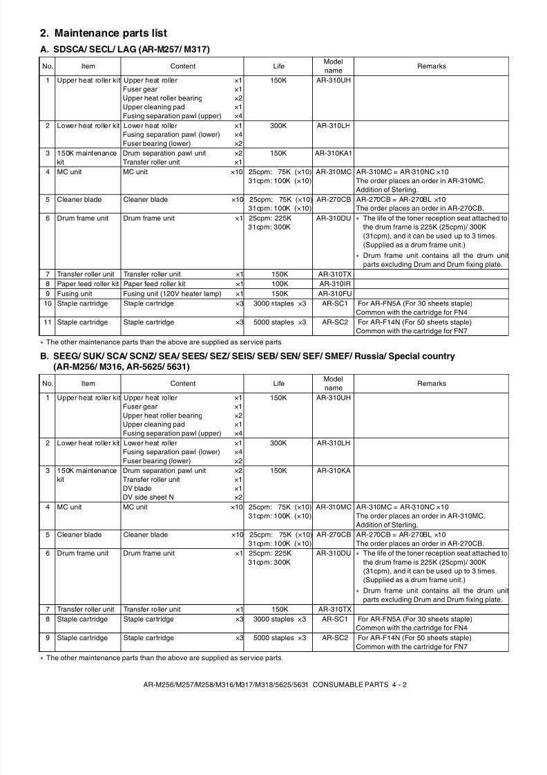
2. Maintenance parts list . . . . . . . . . . . . . . . . . . . . . . . . . . . . 4-2A. SDSCA/ SECL/ LAG (AR-M257/ M317) . . . . . . . . . . . . 4-2B. SEEG/ SUK/ SCA/ SCNZ/ SEA/ SEES/ SEZ/ SEIS/
SEB/ SEN/ SEF/ SMEF/ Russia/ Special country(AR-M256/ M316, AR-5625/ 5631) . . . . . . . . . . . . . . . . 4-2
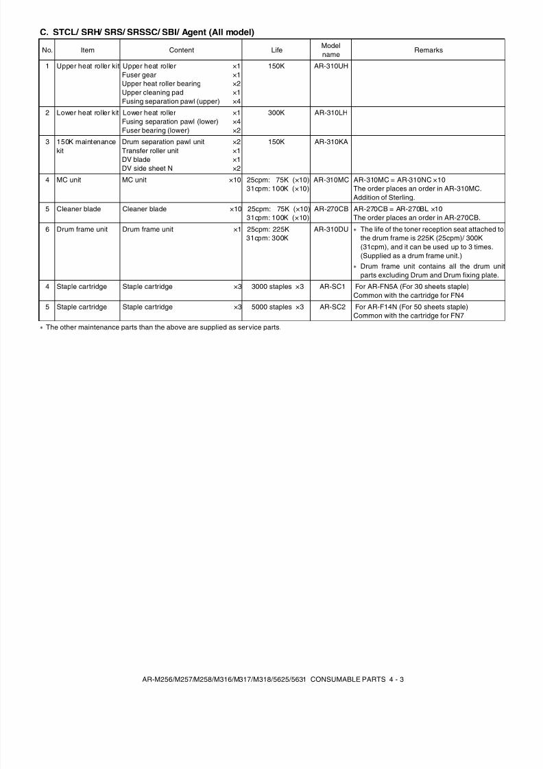
C. STCL/ SRH/ SRS/ SRSSC/ SBI/ Agent (All model) . . . 4-32. Production number identification . . . . . . . . . . . . . . . . . . . . 4-4
<TD cartridge>. . . . . . . . . . . . . . . . . . . . . . . . . . . . . . . . . . 4-4<Drum> . . . . . . . . . . . . . . . . . . . . . . . . . . . . . . . . . . . . . . . 4-4
3. Environment conditions . . . . . . . . . . . . . . . . . . . . . . . . . . . 4-4A. Ambient conditions for transporting. . . . . . . . . . . . . . . . 4-4B. Ambient storage conditions (sealed) . . . . . . . . . . . . . . . 4-4C. Operating ambient conditions . . . . . . . . . . . . . . . . . . . . 4-4
4. Life (packed conditions). . . . . . . . . . . . . . . . . . . . . . . . . . . 4-4
[5] UNPACKING AND INSTALLATION1. Installation. . . . . . . . . . . . . . . . . . . . . . . . . . . . . . . . . . . . . . 5-1
A. Environment . . . . . . . . . . . . . . . . . . . . . . . . . . . . . . . . . . 5-1B. Power source . . . . . . . . . . . . . . . . . . . . . . . . . . . . . . . . . 5-1C. Transport . . . . . . . . . . . . . . . . . . . . . . . . . . . . . . . . . . . . 5-1D. Other precautions. . . . . . . . . . . . . . . . . . . . . . . . . . . . . . 5-2
2. Removal of protective material and fixing screw . . . . . . . . 5-23. Removal and storage of fixing pin . . . . . . . . . . . . . . . . . . . 5-24. Developer cartridge installation . . . . . . . . . . . . . . . . . . . . . 5-3
5. Toner cartridge installation . . . . . . . . . . . . . . . . . . . . . . . . . 5-36. Toner density sensor level adjustment . . . . . . . . . . . . . . . . 5-47. Tray paper size setting . . . . . . . . . . . . . . . . . . . . . . . . . . . . 5-4
A. Trays 1 – 4 . . . . . . . . . . . . . . . . . . . . . . . . . . . . . . . . . . . 5-4B. Manual feed tray. . . . . . . . . . . . . . . . . . . . . . . . . . . . . . . 5-4
8. Installation of options . . . . . . . . . . . . . . . . . . . . . . . . . . . . . 5-5A. AR-P27. . . . . . . . . . . . . . . . . . . . . . . . . . . . . . . . . . . . . . 5-5B. AR-PK1N . . . . . . . . . . . . . . . . . . . . . . . . . . . . . . . . . . . . 5-6C. AR-PF1/PF2 . . . . . . . . . . . . . . . . . . . . . . . . . . . . . . . . . . 5-7D. MX-NSX1 . . . . . . . . . . . . . . . . . . . . . . . . . . . . . . . . . . . . 5-7F. AR-SM5/SM6 . . . . . . . . . . . . . . . . . . . . . . . . . . . . . . . . . 5-8
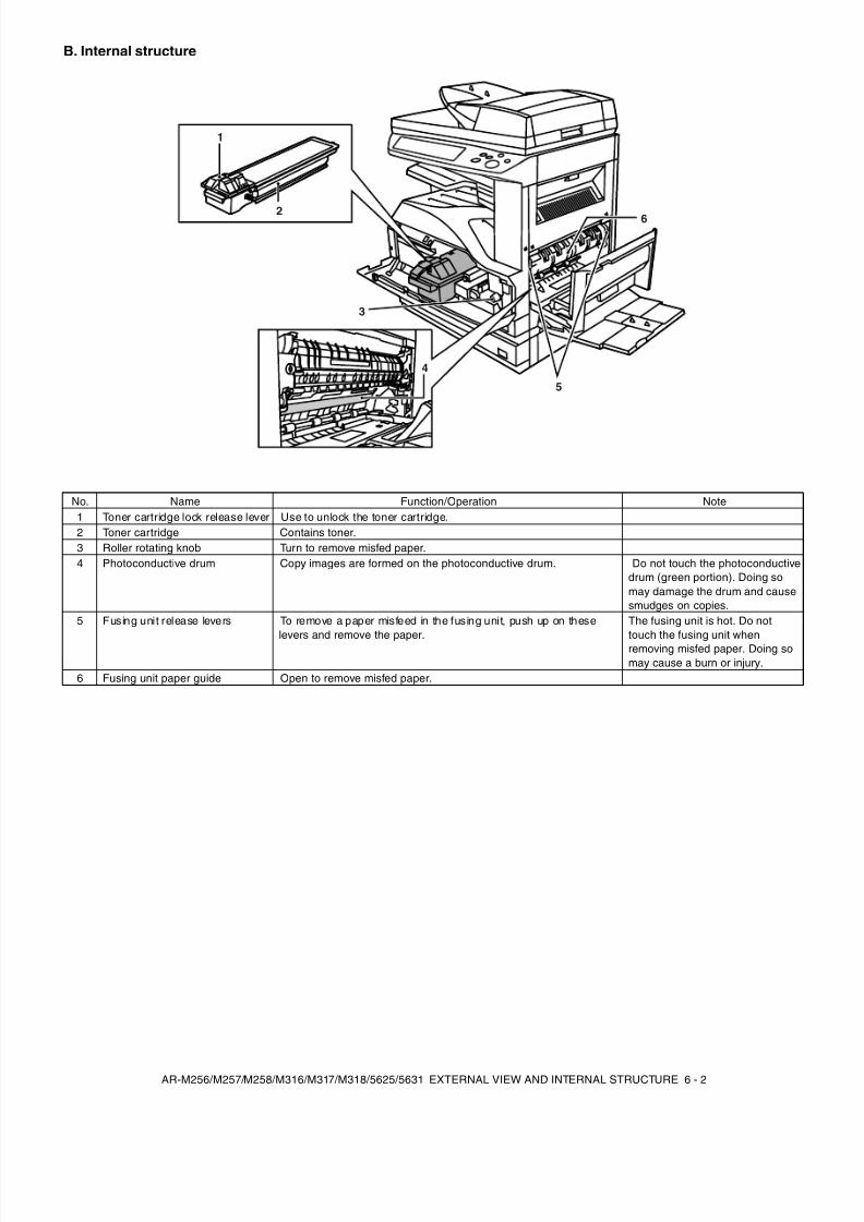
[6] EXTERNAL VIEW AND INTERNAL STRUCTURE1. Name and function of each section . . . . . . . . . . . . . . . . . . 6-1
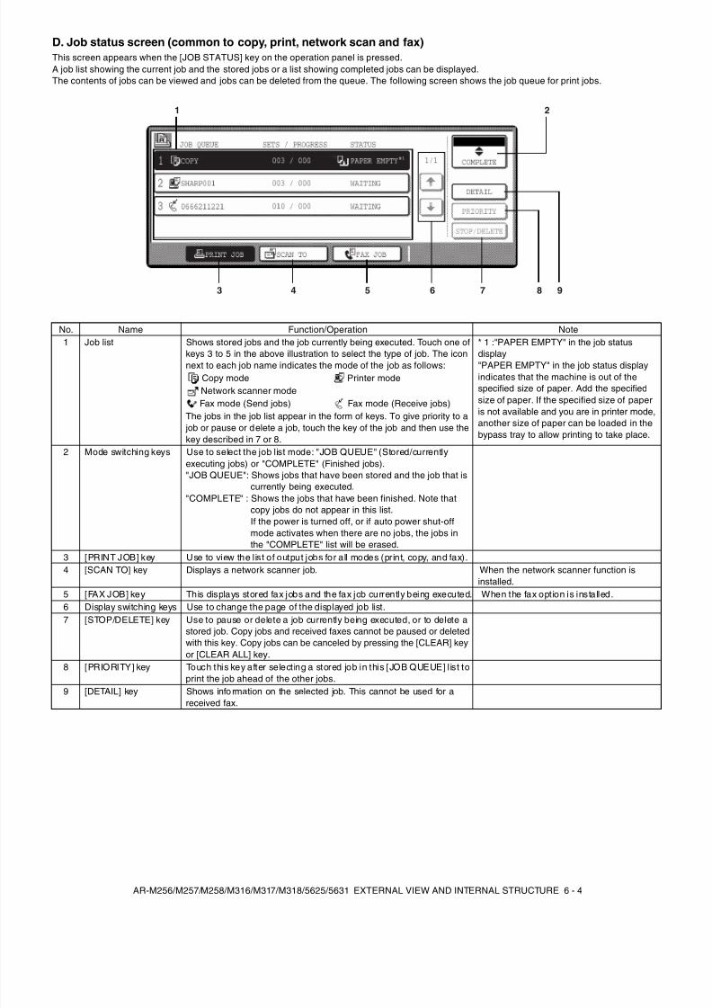
A. External view . . . . . . . . . . . . . . . . . . . . . . . . . . . . . . . . . 6-1B. Internal structure . . . . . . . . . . . . . . . . . . . . . . . . . . . . . . 6-2C. Operation panel . . . . . . . . . . . . . . . . . . . . . . . . . . . . . . . 6-3D. Job status screen
(common to copy, print, network scan and fax) . . . . . . . 6-4E. Motor, Solenoid, Clutch . . . . . . . . . . . . . . . . . . . . . . . . . 6-5F. Sensor . . . . . . . . . . . . . . . . . . . . . . . . . . . . . . . . . . . . . . 6-5G. PWB unit . . . . . . . . . . . . . . . . . . . . . . . . . . . . . . . . . . . . 6-6H. Section . . . . . . . . . . . . . . . . . . . . . . . . . . . . . . . . . . . . . . 6-6
[7] ADJUSTMENTS, SETTING1. List of adjustment items . . . . . . . . . . . . . . . . . . . . . . . . . . . 7-12. Copier adjustment. . . . . . . . . . . . . . . . . . . . . . . . . . . . . . . . 7-1
A. Process section . . . . . . . . . . . . . . . . . . . . . . . . . . . . . . . 7-1B. Mechanism section. . . . . . . . . . . . . . . . . . . . . . . . . . . . . 7-3C. Image density (exposure) adjustment . . . . . . . . . . . . . . 7-9
[8] SIMULATION
(Diagnostics, setup, adjustment value input, data display)1. Outline and purpose . . . . . . . . . . . . . . . . . . . . . . . . . . . . . . 8-12. Code-type simulation . . . . . . . . . . . . . . . . . . . . . . . . . . . . . 8-1
A. Operating procedures and operations . . . . . . . . . . . . . . 8-1B. How to change the simulation adjustment value set
by the touch panel in the adjustment value entryprocess. . . . . . . . . . . . . . . . . . . . . . . . . . . . . . . . . . . . . . 8-1
3. Simulation code list. . . . . . . . . . . . . . . . . . . . . . . . . . . . . . . 8-34. Details. . . . . . . . . . . . . . . . . . . . . . . . . . . . . . . . . . . . . . . . . 8-6
[9] TROUBLE CODE LIST1. List . . . . . . . . . . . . . . . . . . . . . . . . . . . . . . . . . . . . . . . . . . . 9-12. Self diagnostics . . . . . . . . . . . . . . . . . . . . . . . . . . . . . . . . . 9-2
8/9/2019 AR-M318 SM
http://slidepdf.com/reader/full/ar-m318-sm 3/159
[10] DISASSEMBLY, ASSEMBLY AND MAINTENANCE1. Maintenance table . . . . . . . . . . . . . . . . . . . . . . . . . . . . . . 10-1
(For 25cpm) . . . . . . . . . . . . . . . . . . . . . . . . . . . . . . . . . . . 10-1(For 31cpm) . . . . . . . . . . . . . . . . . . . . . . . . . . . . . . . . . . . 10-2
2. Counter clear. . . . . . . . . . . . . . . . . . . . . . . . . . . . . . . . . . 10-33. List of disassembly and assembly . . . . . . . . . . . . . . . . . . 10-34. Details of disassembly and assembly . . . . . . . . . . . . . . . 10-3
A. Process unit . . . . . . . . . . . . . . . . . . . . . . . . . . . . . . . . 10-3B. Developing section . . . . . . . . . . . . . . . . . . . . . . . . . . . 10-5C. Fusing section . . . . . . . . . . . . . . . . . . . . . . . . . . . . . . . 10-6D. Optical section . . . . . . . . . . . . . . . . . . . . . . . . . . . . . . . 10-8
E. Paper feed section . . . . . . . . . . . . . . . . . . . . . . . . . . . 10-9F. Side door unit . . . . . . . . . . . . . . . . . . . . . . . . . . . . . . 10-15G. 1st paper exit unit . . . . . . . . . . . . . . . . . . . . . . . . . . . 10-16H. 2nd paper exit unit. . . . . . . . . . . . . . . . . . . . . . . . . . . 10-17I. Laser unit . . . . . . . . . . . . . . . . . . . . . . . . . . . . . . . . . 10-18J. Power unit . . . . . . . . . . . . . . . . . . . . . . . . . . . . . . . . . 10-18K. PWB . . . . . . . . . . . . . . . . . . . . . . . . . . . . . . . . . . . . . 10-19L. Ozone filter . . . . . . . . . . . . . . . . . . . . . . . . . . . . . . . . 10-21M. Drive section . . . . . . . . . . . . . . . . . . . . . . . . . . . . . . . 10-21N. Transport section . . . . . . . . . . . . . . . . . . . . . . . . . . . 10-23O. Operation section . . . . . . . . . . . . . . . . . . . . . . . . . . . 10-24P. Switch . . . . . . . . . . . . . . . . . . . . . . . . . . . . . . . . . . . . 10-24
[11] OTHERS1. Flash ROM version-up procedure . . . . . . . . . . . . . . . . . . 11-1
A. Program download method
(for Copier, and fax program) . . . . . . . . . . . . . . . . . . . 11-1B. Printer Control Board firmware download method . . . 11-2C. Others (Troubleshooting) . . . . . . . . . . . . . . . . . . . . . . 11-3
2. Key operator program list . . . . . . . . . . . . . . . . . . . . . . . . 11-3A. Common program of digital copier . . . . . . . . . . . . . . . 11-3B. Copy function setting program . . . . . . . . . . . . . . . . . . 11-4C. Printer function setting program . . . . . . . . . . . . . . . . . 11-4D. Network scanner function setting program . . . . . . . . . 11-5
3. E-mail Status/ E-mail Alerts. . . . . . . . . . . . . . . . . . . . . . . 11-6A. Basic functions . . . . . . . . . . . . . . . . . . . . . . . . . . . . . . 11-6B. Main body specifications . . . . . . . . . . . . . . . . . . . . . . . 11-6C. Printer controller specifications . . . . . . . . . . . . . . . . . . 11-6D. Handling of transmission data. . . . . . . . . . . . . . . . . . . 11-6
[12] ELECTRICAL SECTION1. Block diagram . . . . . . . . . . . . . . . . . . . . . . . . . . . . . . . . . 12-1
2. Actual wiring diagram . . . . . . . . . . . . . . . . . . . . . . . . . . . 12-2
8/9/2019 AR-M318 SM
http://slidepdf.com/reader/full/ar-m318-sm 4/159
AR-M256/M257/M258/M316/M317/M318/5625/5631 NOTE FOR SERVICING 1 - 1
[1] NOTE FOR SERVICING
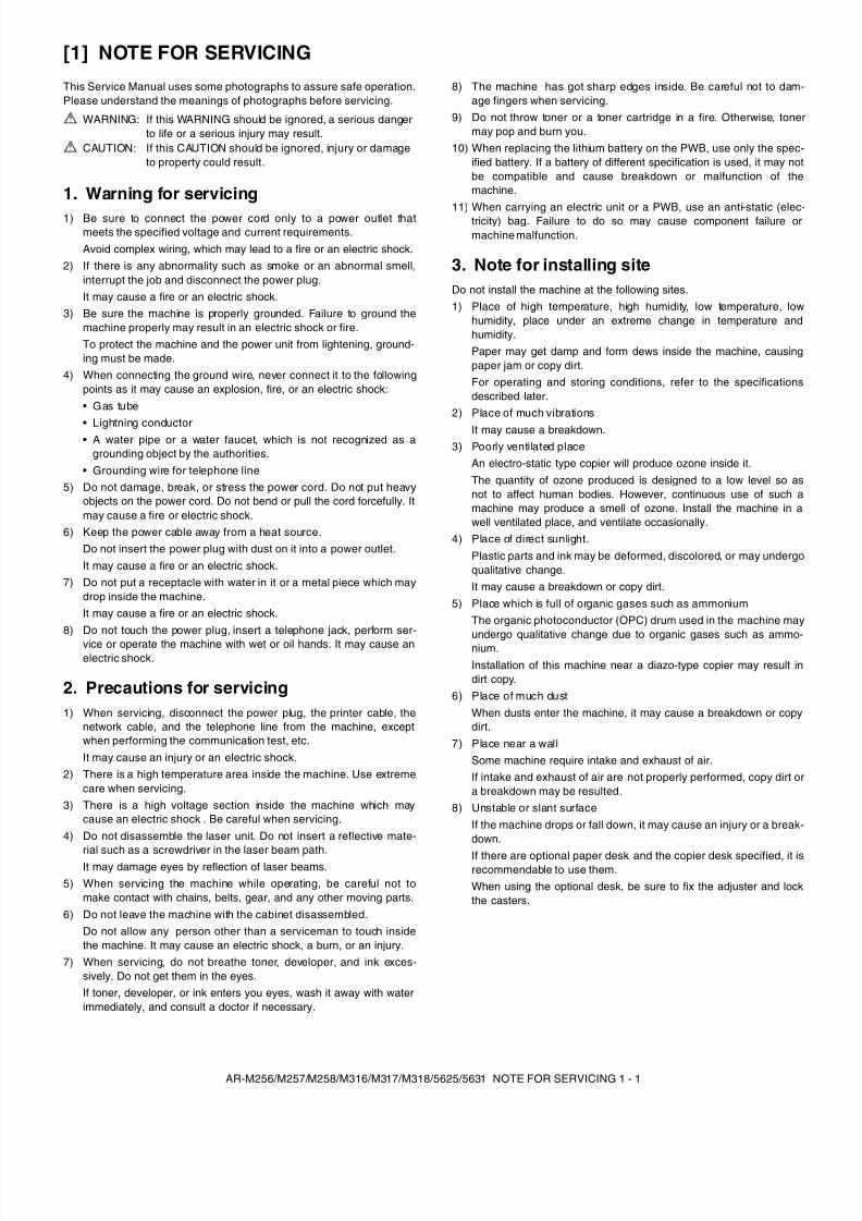
This Service Manual uses some photographs to assure safe operation.Please understand the meanings of photographs before servicing.
1. Warning for servicing1) Be sure to connect the power cord only to a power outlet that
meets the specified voltage and current requirements.Avoid complex wiring, which may lead to a fire or an electric shock.
2) If there is any abnormality such as smoke or an abnormal smell,interrupt the job and disconnect the power plug.It may cause a fire or an electric shock.
3) Be sure the machine is properly grounded. Failure to ground themachine properly may result in an electric shock or fire.To protect the machine and the power unit from lightening, ground-ing must be made.
4) When connecting the ground wire, never connect it to the followingpoints as it may cause an explosion, fire, or an electric shock:• Gas tube
• Lightning conductor• A water pipe or a water faucet, which is not recognized as a
grounding object by the authorities.• Grounding wire for telephone line
5) Do not damage, break, or stress the power cord. Do not put heavyobjects on the power cord. Do not bend or pull the cord forcefully. Itmay cause a fire or electric shock.
6) Keep the power cable away from a heat source.Do not insert the power plug with dust on it into a power outlet.It may cause a fire or an electric shock.
7) Do not put a receptacle with water in it or a metal piece which maydrop inside the machine.It may cause a fire or an electric shock.
8) Do not touch the power plug, insert a telephone jack, perform ser-vice or operate the machine with wet or oil hands. It may cause anelectric shock.
2. Precautions for servicing1) When servicing, disconnect the power plug, the printer cable, the
network cable, and the telephone line from the machine, exceptwhen performing the communication test, etc.It may cause an injury or an electric shock.
2) There is a high temperature area inside the machine. Use extremecare when servicing.
3) There is a high voltage section inside the machine which maycause an electric shock . Be careful when servicing.
4) Do not disassemble the laser unit. Do not insert a reflective mate-
rial such as a screwdriver in the laser beam path.It may damage eyes by reflection of laser beams.5) When servicing the machine while operating, be careful not to
make contact with chains, belts, gear, and any other moving parts.6) Do not leave the machine with the cabinet disassembled.
Do not allow any person other than a serviceman to touch insidethe machine. It may cause an electric shock, a burn, or an injury.
7) When servicing, do not breathe toner, developer, and ink exces-sively. Do not get them in the eyes.If toner, developer, or ink enters you eyes, wash it away with waterimmediately, and consult a doctor if necessary.
8) The machine has got sharp edges inside. Be careful not to dam-age fingers when servicing.
9) Do not throw toner or a toner cartridge in a fire. Otherwise, tonermay pop and burn you.
10) When replacing the lithium battery on the PWB, use only the spec-ified battery. If a battery of different specification is used, it may notbe compatible and cause breakdown or malfunction of themachine.
11) When carrying an electric unit or a PWB, use an anti-static (elec-tricity) bag. Failure to do so may cause component failure ormachine malfunction.
3. Note for installing siteDo not install the machine at the following sites.1) Place of high temperature, high humidity, low temperature, low
humidity, place under an extreme change in temperature andhumidity.Paper may get damp and form dews inside the machine, causingpaper jam or copy dirt.For operating and storing conditions, refer to the specificationsdescribed later.
2) Place of much vibrations
It may cause a breakdown.3) Poorly ventilated place
An electro-static type copier will produce ozone inside it.The quantity of ozone produced is designed to a low level so asnot to affect human bodies. However, continuous use of such amachine may produce a smell of ozone. Install the machine in awell ventilated place, and ventilate occasionally.
4) Place of direct sunlight.Plastic parts and ink may be deformed, discolored, or may undergoqualitative change.It may cause a breakdown or copy dirt.
5) Place which is full of organic gases such as ammoniumThe organic photoconductor (OPC) drum used in the machine mayundergo qualitative change due to organic gases such as ammo-nium.Installation of this machine near a diazo-type copier may result indirt copy.
6) Place of much dustWhen dusts enter the machine, it may cause a breakdown or copydirt.
7) Place near a wallSome machine require intake and exhaust of air.If intake and exhaust of air are not properly performed, copy dirt ora breakdown may be resulted.
8) Unstable or slant surfaceIf the machine drops or fall down, it may cause an injury or a break-down.
If there are optional paper desk and the copier desk specified, it isrecommendable to use them.When using the optional desk, be sure to fix the adjuster and lockthe casters.
WARNING: If this WARNING should be ignored, a serious dangerto life or a serious injury may result.
CAUTION: If this CAUTION should be ignored, injury or damageto property could result.
8/9/2019 AR-M318 SM
http://slidepdf.com/reader/full/ar-m318-sm 5/159
8/9/2019 AR-M318 SM
http://slidepdf.com/reader/full/ar-m318-sm 6/159
AR-M256/M257/M258/M316/M317/M318/5625/5631 CONFIGURATION 2 - 2
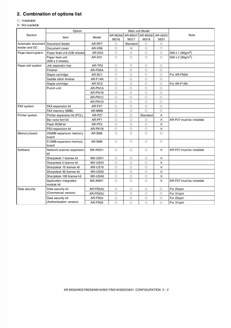
2. Combination of options listF : Installable
: Not available
SectionOption Main unit Model
NoteItem Model
AR-M256/ M316
AR-M257/ M317
AR-M258/ M318
AR-5625/ 5631
Automatic documentfeeder and OC
Document feeder AR-RP7 F Standard F F
Document cover AR-VR6 F F F
Paper feed system Paper feed un it (500 sheets) AR-D30 F F F F 500 x 1 (80g/m 2)
Paper feed unit(500 x 2 sheets)
AR-D31 F F F F 500 x 2 (80g/m 2)
Paper exit system Job separator tray AR-TR3 F F F F
Finisher AR-FN5A F F F F
Staple cartridge AR-SC1 F F F F For AR-FN5ASaddle stitch finisher AR-F14N F F F F
Staple cartridge AR-SC2 F F F F For AR-F14NPunch unit AR-PN1A F F F F
AR-PN1B F F F F
AR-PN1C F F F F
AR-PN1D F F F F
FAX system FAX expansion kit AR-FX7 F F F F
FAX memory (8MB) AR-MM9 F F F F
Printer system Printer expansion kit (PCL) AR-P27 F F StandardBar code font kit AR-PF1 F F F AR-P27 must be installed.Flash ROM kit AR-PF2 F F F
PS3 expansion kit AR-PK1N F F F
Memory board 256MB expansion memoryboard
AR-SM5 F F F F
512MB expansion memoryboard
AR-SM6 F F F F
Software Network scanner expansionkit
MX-NSX1 F F F AR-P27 must be installed.
Sharpdesk 1 license kit MX-USX1 F F F
Sharpdesk 5 license kit MX-USX5 F F F
Sharpdesk 10 license kit MX-US10 F F F
Sharpdesk 50 license kit MX-US50 F F F Sharpdesk 100 license k it MX-USA0 F F F
Application integrationmodule kit
MX-AMX1 F F F AR-P27 must be installed.
Data security Data security kit(Commercial version)
AR-FR24U F F F F For 25cpmAR-FR25U F F F F For 31cpm
Data security kit(Authentication version)
AR-FR24 F F F F For 25cpmAR-FR25 F F F F For 31cpm
8/9/2019 AR-M318 SM
http://slidepdf.com/reader/full/ar-m318-sm 7/159
AR-M256/M257/M258/M316/M317/M318/5625/5631 SPECIFICATIONS 3 - 1
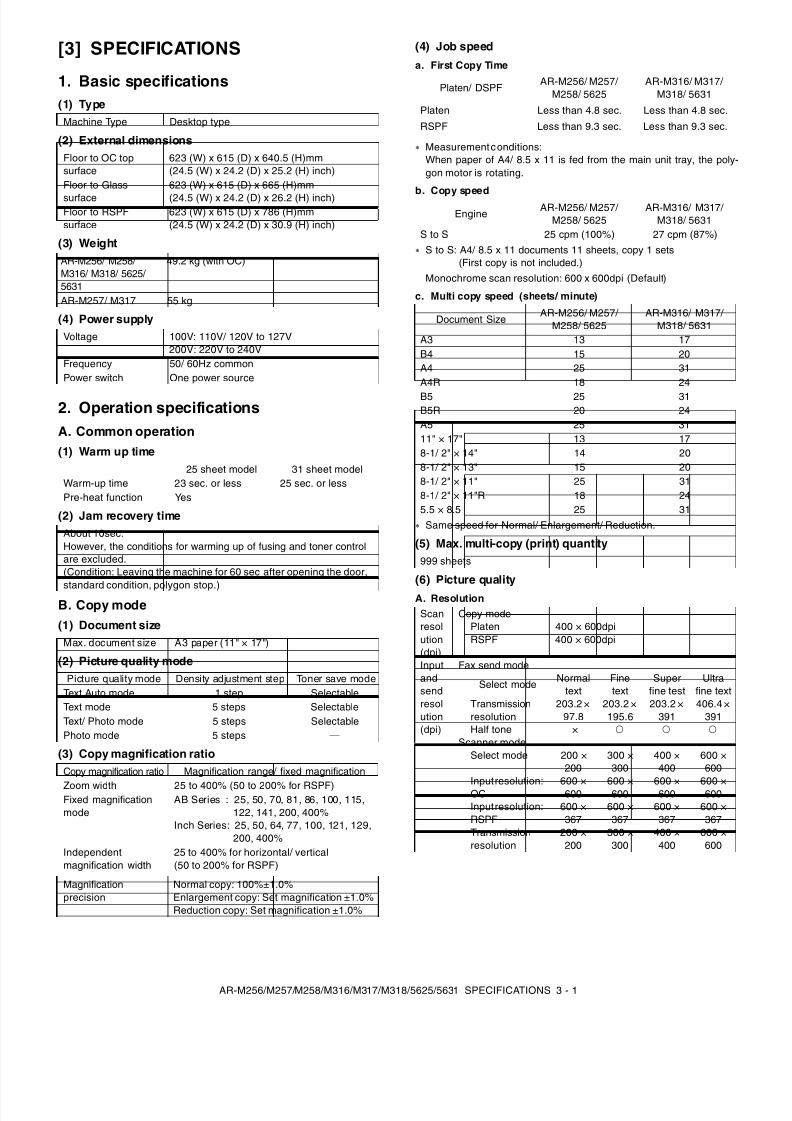
[3] SPECIFICATIONS
1. Basic specifications(1) Type
(2) External dimensions
(3) Weight
(4) Power supply
2. Operation specificationsA. Common operation(1) Warm up time
(2) Jam recovery time
B. Copy mode(1) Document size
(2) Picture quality mode
(3) Copy magnification ratio
(4) Job speed
a. First Copy Time
Measurement conditions:When paper of A4/ 8.5 x 11 is fed from the main unit tray, the poly-gon motor is rotating.
b. Copy speed
S to S: A4/ 8.5 x 11 documents 11 sheets, copy 1 sets(First copy is not included.)
Monochrome scan resolution: 600 x 600dpi (Default)
c. Multi copy speed (sheets/ minute)
Same speed for Normal/ Enlargement/ Reduction.
(5) Max. multi-copy (print) quantity
(6) Picture quality
A. Resolution
Machine Type Desktop type
Floor to OC topsurface
623 (W) x 615 (D) x 640.5 (H)mm(24.5 (W) x 24.2 (D) x 25.2 (H) inch)
Floor to Glasssurface
623 (W) x 615 (D) x 665 (H)mm(24.5 (W) x 24.2 (D) x 26.2 (H) inch)
Floor to RSPFsurface
623 (W) x 615 (D) x 786 (H)mm(24.5 (W) x 24.2 (D) x 30.9 (H) inch)
AR-M256/ M258/M316/ M318/ 5625/5631
49.2 kg (with OC)
AR-M257/ M317 55 kg
Voltage 100V: 110V/ 120V to 127V200V: 220V to 240V
Frequency 50/ 60Hz commonPower switch One power source
25 sheet model 31 sheet modelWarm-up time 23 sec. or less 25 sec. or lessPre-heat function Yes
About 10sec.However, the conditions for warming up of fusing and toner controlare excluded.(Condition: Leaving the machine for 60 sec after opening the door,
standard condition, polygon stop.)
Max. document size A3 paper (11" × 17")
Picture quality mode Density adjustment step Toner save modeText Auto mode 1 step SelectableText mode 5 steps SelectableText/ Photo mode 5 steps SelectablePhoto mode 5 steps —
Copy magnification ratio Magnification range/ fixed magnification
Zoom width 25 to 400% (50 to 200% for RSPF)Fixed magnificationmode
AB Series : 25, 50, 70, 81, 86, 100, 115,122, 141, 200, 400%
Inch Series: 25, 50, 64, 77, 100, 121, 129,200, 400%
Independentmagnification width
25 to 400% for horizontal/ vertical(50 to 200% for RSPF)
Magnificationprecision
Normal copy: 100%±1.0%Enlargement copy: Set magnification ±1.0%Reduction copy: Set magnification ±1.0%
Platen/ DSPFAR-M256/ M257/
M258/ 5625AR-M316/ M317/
M318/ 5631
Platen Less than 4.8 sec. Less than 4.8 sec.
RSPF Less than 9.3 sec. Less than 9.3 sec.
Engine AR-M256/ M257/M258/ 5625
AR-M316/ M317/M318/ 5631
S to S 25 cpm (100%) 27 cpm (87%)
Document SizeAR-M256/ M257/
M258/ 5625AR-M316/ M317/
M318/ 5631A3 13 17B4 15 20A4 25 31A4R 18 24B5 25 31B5R 20 24A5 25 3111" × 17" 13 178-1/ 2" × 14" 14 208-1/ 2" × 13" 15 208-1/ 2" × 11" 25 318-1/ 2" × 11"R 18 245.5 × 8.5 25 31
999 sheets
Scanresolution(dpi)
Copy modePlaten 400 × 600dpiRSPF 400 × 600dpi
Inputandsendresolution(dpi)
Fax send mode
Select mode Normaltext
Finetext
Superfine test
Ultrafine text
Transmissionresolution
203.2 ×97.8
203.2 ×195.6
203.2 ×391
406.4 ×391
Half tone × F F F
Scanner modeSelect mode 200 ×
200300 ×300
400 ×400
600 ×600
Input resolution:OC 600 ×600 600 ×600 600 ×600 600 ×600Input resolution:RSPF
600 ×367
600 ×367
600 ×367
600 ×367
Transmissionresolution
200 ×200
300 ×300
400 ×400
600 ×600
8/9/2019 AR-M318 SM
http://slidepdf.com/reader/full/ar-m318-sm 8/159
AR-M256/M257/M258/M316/M317/M318/5625/5631 SPECIFICATIONS 3 - 2
b. Gradation
3. Engine specificationsA. Operation and display section
B. Paper feed, transport, paper exit section
(1) Paper feed ability
• Tray 1
• Tray 2
• Manual feed section
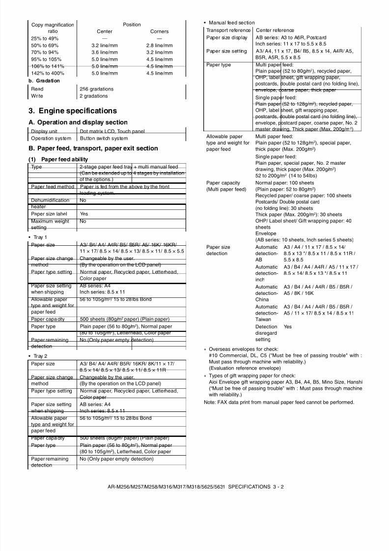
Overseas envelopes for check:#10 Commercial, DL, C5 ("Must be free of passing trouble" with :Must pass through machine with reliability.)(Evaluation reference envelope)Types of gift wrapping paper for check:Aioi Envelope gift wrapping paper A3, B4, A4, B5, Mino Size, Hanshi(“Must be free of passing trouble” with : Must pass through machinewith reliability.)
Note: FAX data print from manual paper feed cannot be performed.
Copy magnificationratio
PositionCenter Corners
25% to 49% — —50% to 69% 3.2 line/mm 2.8 line/mm70% to 94% 3.6 line/mm 3.2 line/mm95% to 105% 5.0 line/mm 4.5 line/mm106% to 141% 5.0 line/mm 4.5 line/mm142% to 400% 5.0 line/mm 4.5 line/mm
Read 256 gradations
Write 2 gradations
Display unit Dot matrix LCD, Touch panelOperation system Button switch system
Type 2-stage paper feed tray + multi manual feed(Can be extended up to 4 stages by installationof the options.)
Paper feed method Paper is fed from the above by the front
loading system.Dehumidificationheater
No
Paper size label YesMaximum weightsetting
No
Paper size A3/ B4/ A4/ A4R/ B5/ B5R/ A5/ 16K/ 16KR/11 × 17/ 8.5 × 14/ 8.5 × 13/ 8.5 × 11/ 8.5 × 5.5
Paper size changemethod
Changeable by the user.(By the operation on the LCD panel)
Paper type setting Normal paper, Recycled paper, Letterhead,Color paper
Paper size settingwhen shipping
AB series: A4Inch series: 8.5 x 11
Allowable papertype and weight forpaper feed
56 to 105g/ m2 / 15 to 28 lbs Bond
Paper capacity 500 sheets (80g/ m2 paper) (Plain paper)Paper type Plain paper (56 to 80g/ m2), Normal paper
(80 to 105g/ m2), Letterhead, Color paperPaper remainingdetection
No (Only paper empty detection)
Paper size A3/ B4/ A4/ A4R/ B5R/ 16KR/ 8K/11 × 17/8.5 × 14/ 8.5 × 13/ 8.5 × 11/ 8.5 × 11R
Paper size change
method
Changeable by the user.
(By the operation on the LCD panel)Paper type setting Normal paper, Recycled paper, Letterhead,Color paper
Paper size settingwhen shipping
AB series: A4Inch series: 8.5 x 11
Allowable papertype and weight forpaper feed
56 to 105g/ m2 / 15 to 28 lbs Bond
Paper capacity 500 sheets (80g/ m2 paper) (Plain paper)Paper type Plain paper (56 to 80g/ m2), Normal paper
(80 to 105g/ m2), Letterhead, Color paperPaper remainingdetection
No (Only paper empty detection)
Transport reference Center referencePaper size display AB series: A3 to A6R, Postcard
Inch series: 11 x 17 to 5.5 x 8.5Paper size setting A3/ A4, 11 x 17, B4/ B5, 8.5 x 14, A4R/ A5,
B5R, A5R, 5.5 x 8.5Paper type Multi paper feed:
Plain paper (52 to 80g/ m2), recycled paper,OHP, label sheet, gift wrapping paper,postcards, double postal card (no folding line),envelope, coarse paper, thick paper
Single paper feed:Plain paper (52 to 128g/m 2), recycled paper,OHP, label sheet, gift wrapping paper,postcards, double postal card (no folding line),envelope, postcard paper, coarse paper, No. 2master drawing, Thick paper (Max. 200g/m 2)
Allowable papertype and weight forpaper feed
Multi paper feed:Plain paper (52 to 128g/ m2), special paper,thick paper (Max. 200g/ m2)Single paper feed:Plain paper, special paper, No. 2 masterdrawing, thick paper (Max. 200g/ m2)52 to 200g/ m2 (14 to 54lbs)
Paper capacity(Multi paper feed)
Normal paper: 100 sheets(Plain paper: 52 to 80g/ m2)Recycled paper/ coarse paper: 100 sheetsPostcards/ Double postal card(no folding line): 30 sheetsThick paper (Max. 200g/ m2): 30 sheetsOHP/ Label sheet/ Gift wrapping paper: 40sheetsEnvelope(AB series: 10 sheets, Inch series 5 sheets)
Paper sizedetection
Automaticdetection-AB
A3 / A4 / 11 x 17 / 8.5 × 14/8.5 x 13 */ 8.5 x 11 / 8.5 x 11R /5.5 x 8.5
Automaticdetection-inch
A3 / B4 / A4 / A4R / A5 / 11 x 17 /8.5 × 14/ 8.5 x 13 */ 8.5 x 11
Automaticdetection-China
A3 / B4 / A4 / A4R / B5 / B5R /A5 / 8K / 16K
Automaticdetection-Taiwan
A3 / B4 / A4 / A4R / B5 / B5R /A5 / 11 × 17/ 8.5 x 14 / 8.5 x 11
Detectiondisregardsetting
Yes
8/9/2019 AR-M318 SM
http://slidepdf.com/reader/full/ar-m318-sm 9/159
AR-M256/M257/M258/M316/M317/M318/5625/5631 SPECIFICATIONS 3 - 3
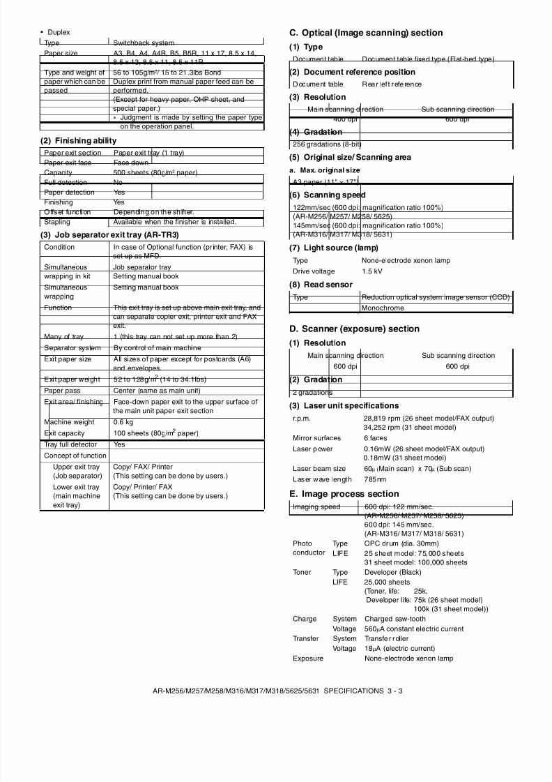
• Duplex
(2) Finishing ability
(3) Job separator exit tray (AR-TR3)
C. Optical (Image scanning) section(1) Type
(2) Document reference position
(3) Resolution
(4) Gradation
(5) Original size/ Scanning area
a. Max. original size
(6) Scanning speed
(7) Light source (lamp)
(8) Read sensor
D. Scanner (exposure) section(1) Resolution
(2) Gradation
(3) Laser unit specifications
E. Image process section
Type Switchback systemPaper size A3, B4, A4, A4R, B5, B5R, 11 x 17, 8.5 x 14,
8.5 x 13, 8.5 x 11, 8.5 x 11RType and weight ofpaper which can bepassed
56 to 105g/ m2 / 15 to 21 .3lbs BondDuplex print from manual paper feed can beperformed.(Except for heavy paper, OHP sheet, andspecial paper.)
Judgment is made by setting the paper typeon the operation panel.
Paper exit section Paper exit tray (1 tray)Paper exit face Face downCapacity 500 sheets (80g/ m2 paper)Full detection NoPaper detection YesFinishing YesOffset function Depending on the sh ifter.Stapling Available when the finisher is installed.
Condition In case of Optional function (pr inter, FAX) isset up as MFD.
Simultaneouswrapping in kit
Job separator traySetting manual book
Simultaneouswrapping
Setting manual book
Function This exit tray is set up above main exit tray, andcan separate copier exit, printer exit and FAXexit.
Many of tray 1 (this tray can not set up more than 2)
Separator system By control of main machine
Exit paper size All sizes of paper except for postcards (A6)and envelopes.
Exit paper weight 52 to 128g/m 2 (14 to 34.1lbs)
Paper pass Center (same as main unit)
Exit area/ finishing Face-down paper exit to the upper surface of
the main unit paper exit sectionMachine weight 0.6 kg
Exit capacity 100 sheets (80g/m 2 paper)
Tray full detector Yes
Concept of function
Upper exit tray(Job separator)
Copy/ FAX/ Printer(This setting can be done by users.)
Lower exit tray(main machineexit tray)
Copy/ Printer/ FAX(This setting can be done by users.)
Document table Document table fixed type (Flat-bed type)
Document table Rear lef t reference
Main scanning direction Sub scanning direction400 dpi 600 dpi
256 gradations (8-bit)
A3 paper (11" × 17")
122mm/sec (600 dpi: magnification ratio 100%)(AR-M256/ M257/ M258/ 5625)145mm/sec (600 dpi: magnification ratio 100%)(AR-M316/ M317/ M318/ 5631)
Type None-electrode xenon lamp
Drive voltage 1.5 kV
Type Reduction optical system image sensor (CCD)Monochrome
Main scanning direction Sub scanning direction600 dpi 600 dpi
2 gradations
r.p.m. 28,819 rpm (26 sheet model/FAX output)34,252 rpm (31 sheet model)
Mirror surfaces 6 facesLaser p ower 0.16mW (26 sheet model/FAX output)
0.18mW (31 sheet model)Laser beam size 60 µ (Main scan) x 70 µ (Sub scan) Laser wave length 785nm
Imaging speed 600 dpi: 122 mm/sec.(AR-M256/ M257/ M258/ 5625)600 dpi: 145 mm/sec.(AR-M316/ M317/ M318/ 5631)
Photoconductor
Type OPC drum (dia. 30mm)LIFE 25 sheet model: 75,000 sheets
31 sheet model: 100,000 sheetsToner Type Developer (Black)
LIFE 25,000 sheets(Toner, life: 25k,Developer life: 75k (26 sheet model)
100k (31 sheet model))Charge System Charged saw-tooth
Voltage 560 µA constant electric currentTransfer System Transfe r roller
Voltage 18 µA (electric current)Exposure None-electrode xenon lamp
8/9/2019 AR-M318 SM
http://slidepdf.com/reader/full/ar-m318-sm 10/159
AR-M256/M257/M258/M316/M317/M318/5625/5631 SPECIFICATIONS 3 - 4
F. Fusing
G. Drive
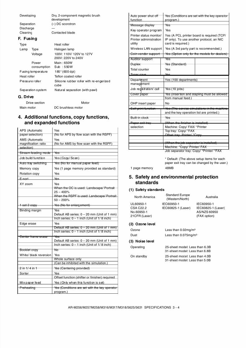
4. Additional functions, copy functions,and expanded functions
5. Safety and environmental protection
standards(1) Safety standards
(2) Ozone level
(3) Noise level
Developing Dry, 2-component magnetic brushdevelopment
Separation (–) DC scorotronDischarge —Cleaning Contacted blade
Type Heat rollerLamp Type Halogen lamp
Voltage 100V: 110V/ 120V to 127V200V: 220V to 240V
Powerconsumption
Main : 650WSub : 550W
Fusing temperature 185° (600 dpi)Heat roller Teflon coated rollerPressure roller Silicone rubber ro ller with re-enger ized
cubeSeparation system Natural separation (with pawl)
Drive section MotorMain motor DC brushless motor
APS (Automaticpaper selection)
Yes(No for APS by flow scan with the RSPF)
AMS (Automaticmagnification ratioselection)
Yes(No for AMS by flow scan with the RSPF)
Stream feeding mode Yes
Job bu ild funct ion Yes (Copy/ Scan)
Auto tray switching Yes (No for manual paper feed)
Memory copy Yes (1 page memory provided as standard)
Rotation copy Yes
E-sort Yes
XY zoom YesWhen the OC is used: Landscape/ Portrait25 – 400%When the RSPF is used: Landscape/ Portrait50 – 200%
1 set 2 copy Yes (No for enlargement)
Binding margin YesDefault AB series: 0 – 20 mm (Unit of 1 mm)Inch series: 0 – 1 inch (Unit of 1/ 8 inch)
Edge erase YesDefault AB series: 0 – 20 mm (Unit of 1 mm)Inch series: 0 – 1 inch (Unit of 1/ 8 inch)
Center frame erase YesDefault AB series: 0 – 20 mm (Unit of 1 mm)Inch series: 0 – 1 inch (Unit of 1/ 8 inch)
Booklet copy No
White/ black reversion YesWhole surface only(Can be inhibited with the simulation.)
2 in 1/ 4 in 1 Yes (Centering provided)
Sorter YesOffset function (shifter or finisher) required
Mix paper feed Yes (Only when th is function is set)
Preheating Yes (Conditions are set with the key operatorprogram.)
Auto power shut offfunction
Yes (Conditions are set with the key operatorprogram.)
Message display Yes
Key operator program Yes
Printer status monitor/Printer administrationutility
Yes (A PCL printer board is required (TCP/ IP only). To use another protocol, an NICcard is required.)
Wireless LAN support Yes (A 3rd party part is recommended.)
Coin vendor support Yes (Option only for the models for dealers)
Auditor support Yes
Duplex Yes (Standard)
Total counter Yes
Toner save Yes
Departmentmanagement
Yes (100 departments)
Job registration/ call Yes (10 jobs)
Cover paper Yes (Inser tion and stapling must be allowedfrom manual feed.)
OHP insert paper No
Self print function Yes (The service simulations in the machineand the key operation list are printed.)
Built-in clock Yes
Paper exit trayselection
(When the finisher is installed)Machine: Copy/ FAX/ *PrinterTop tray: Copy/ *FAXOffset tray: Printer/ *Copy
(When the job separator is installed)Machine: *Copy/ Printer/ FAXJob separator tray: Copy/ *Printer/ *FAX
* Default: (The above setup items for eachpaper exit tray can be changed by the user.)
1 page memory 48MB
North AmericaStandard Europe(Western/North)
Australia
UL60950-1CSA C22.2No.60950-121CFR (Laser)
IEC60950-1IEC60825-1 (Laser)
IEC60950-1IEC60825-1 (Laser)AS/NZS 60950(FAX option)
Ozone Less than 0.02mg/m³
Dust Less than 0.075mg/m³
Operating 25-sheet model: Less than 6.3B31-sheet model: Less than 6.8B
On standby 25-sheet model: Less than 4.0B31-sheet model: Less than 5.0B
8/9/2019 AR-M318 SM
http://slidepdf.com/reader/full/ar-m318-sm 11/159
AR-M256/M257/M258/M316/M317/M318/5625/5631 SPECIFICATIONS 3 - 5
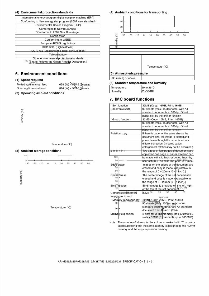
(4) Environmental protection standards
6. Environment conditions(1) Space required
(2) Operating ambient conditions
(3) Ambient storage conditions
(4) Ambient conditions for transporting
(5) Atmospheric pressure
(6) Standard temperature and humidity
7. IMC board functions
Note: The number of sheets for the columns marked with “*” is calcu-lated supposing that the same quantity is assigned to the ROPMmemory and the copy expansion memory.
International energy program digital complex machine (EPA)Conforming to New energy star program (2007 new standard)
Environmental Choice Program (ECP)Conforming to New Blue Angel
* Conforms to 2007 New Blue Angel.Nordic swan
Conforming to WEEEEuropean ROHS regulations
ISO11798 (Lightfastness)
ISO19752 (Measures the toner consumption)Taiwan batteryOther environmental protection standards
(Sharp: Follows the Green Product Declaration.)
Folded multi manual feed 628 (W) × 585.5 (D) mmOpen multi manual feed 894 (W) × 585.5 (D) mm
Temperature (˚C)
H u m
i d i t y ( % )
Temperature (˚C)
H u m
i d i t y ( % )
595 mmHg or above
Temperature 20 to 25°CHumidity 65±5%RH
* Sort function(Electronic sort)
32MB (Copy: 16MB, Print: 16MB)90 sheets (max. 1500 sheets) with A4standard documents at 600dpi. Offsetpaper exit by the shifter function
* Grou p function 32MB (Copy: 16MB, Print: 16MB)90 sheets (max. 1500 sheets) with A4standard documents at 600dpi. Offsetpaper exit by the shifter function
Rotation copy If there is paper of the same size as thedocument size, the image is rotated andprinted even though the paper is set in adifferent direction. (In some cases,enlargement rotation may not be executed.)
2 in 1/ 4 in 1 Two pages or four pages of documents arecopied on one page of paper. Division canbe made with slid lines or dotted lines (byuser setup). (The solid line width is 8 lines)
Edge erase Images on the edges of the document areerased and copy is made. (Adjustable inthe range of 0 – 20mm (0 – 1 inch).)
Center erase The center image of the set document iserased and copy is made. (Adjustable inthe range of 0 – 20mm (0 – 1 inch).)
Binding edge Binding edge is provided on the left, rightor the top of the set document.
Compression memoryfor electronic sort
32MB
* Memory read capacity 32MB (Copy: 16MB, Print: 16MB)90 sheets (Max. 1500 sheets) of A4
standard documents (Sharp A4 standarddocument Test Chart B (6%))Memory expansion 2 slots for DIMM memory, Max. 512MB x 2
slots + 32MB (Expandable up to 1056MB)
Temperature (˚C)
H u m
i d i t y ( % )
8/9/2019 AR-M318 SM
http://slidepdf.com/reader/full/ar-m318-sm 12/159
AR-M256/M257/M258/M316/M317/M318/5625/5631 SPECIFICATIONS 3 - 6
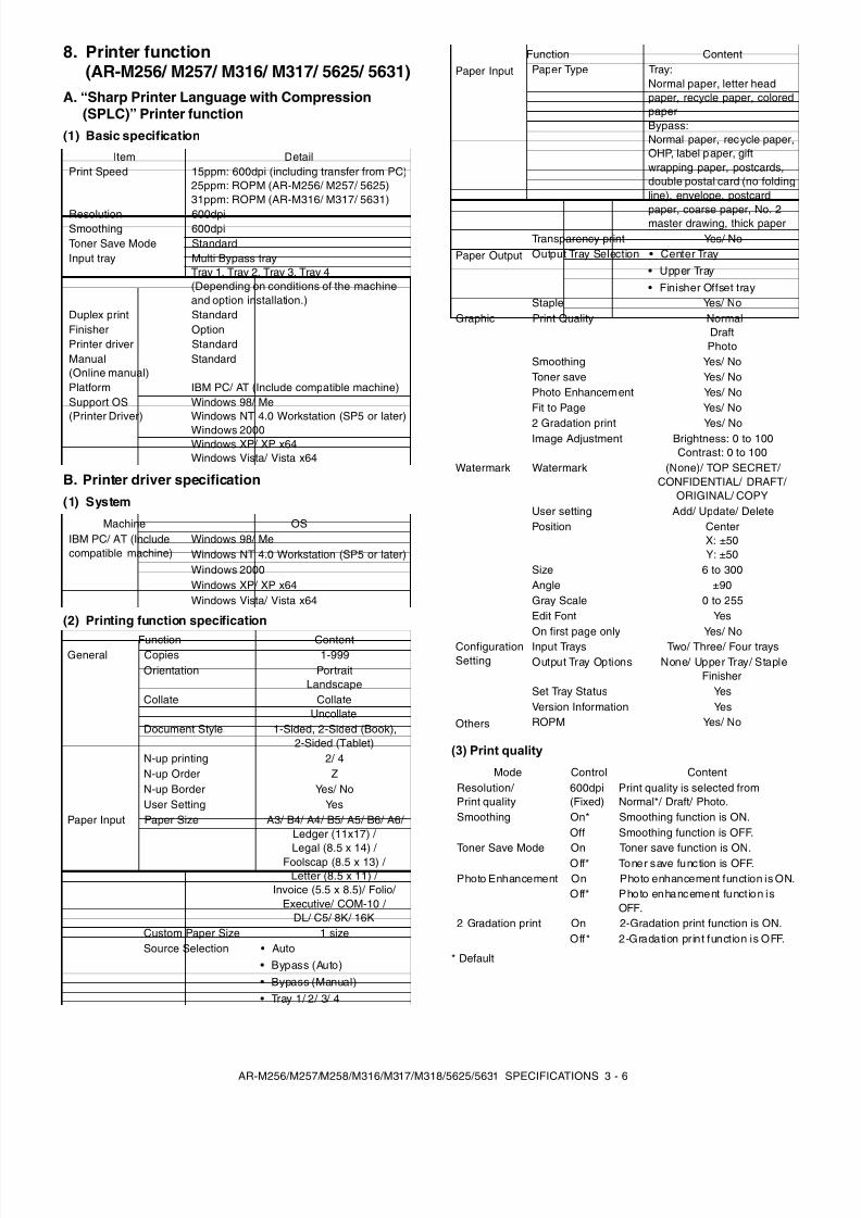
8. Printer function(AR-M256/ M257/ M316/ M317/ 5625/ 5631)
A. “Sharp Printer Language with Compression(SPLC)” Printer function
(1) Basic specification
B. Printer driver specification(1) System
(2) Printing function specification
(3) Print quality
* Default
Item DetailPrint Speed 15ppm: 600dpi (including transfer from PC)
25ppm: ROPM (AR-M256/ M257/ 5625)31ppm: ROPM (AR-M316/ M317/ 5631)
Resolution 600dpiSmoothing 600dpiToner Save Mode StandardInput tray Multi Bypass tray
Tray 1, Tray 2, Tray 3, Tray 4(Depending on conditions of the machineand option installation.)
Duplex print StandardFinisher OptionPrinter driver StandardManual(Online manual)
Standard
Platform IBM PC/ AT (Include compatible machine)Support OS(Printer Driver)
Windows 98/ MeWindows NT 4.0 Workstation (SP5 or later)Windows 2000Windows XP/ XP x64Windows Vista/ Vista x64
Machine OSIBM PC/ AT (Includecompatible machine)
Windows 98/ MeWindows NT 4.0 Workstation (SP5 or later)Windows 2000Windows XP/ XP x64Windows Vista/ Vista x64
Function ContentGeneral Copies 1-999
Orientation PortraitLandscape
Collate CollateUncollate
Document Style 1-Sided, 2-Sided (Book),2-Sided (Tablet)
N-up printing 2/ 4N-up Order ZN-up Border Yes/ NoUser Setting Yes
Paper Input Paper Size A3/ B4/ A4/ B5/ A5/ B6/ A6/Ledger (11x17) /
Legal (8.5 x 14) / Foolscap (8.5 x 13) / Letter (8.5 x 11) /
Invoice (5.5 x 8.5)/ Folio/Executive/ COM-10 /
DL/ C5/ 8K/ 16KCustom Paper Size 1 sizeSource Selection • Auto
• Bypass (Auto)• Bypass (Manual)• Tray 1/ 2/ 3/ 4
Paper Input Paper Type Tray:Normal paper, letter headpaper, recycle paper, coloredpaperBypass:Normal paper, recycle paper,OHP, label paper, giftwrapping paper, postcards,double postal card (no foldingline), envelope, postcard
paper, coarse paper, No. 2master drawing, thick paperTransparency print Yes/ No
Paper Output Output Tray Selection • Center Tray• Upper Tray• Finisher Offset tray
Staple Yes/ NoGraphic Print Quality Normal
DraftPhoto
Smoothing Yes/ NoToner save Yes/ NoPhoto Enhancement Yes/ NoFit to Page Yes/ No
2 Gradation print Yes/ NoImage Adjustment Brightness: 0 to 100
Contrast: 0 to 100Watermark Watermark (None)/ TOP SECRET/
CONFIDENTIAL/ DRAFT/ORIGINAL/ COPY
User setting Add/ Update/ DeletePosition Center
X: ±50Y: ±50
Size 6 to 300Angle ±90Gray Scale 0 to 255Edit Font YesOn first page only Yes/ No
ConfigurationSetting
Input Trays Two/ Three/ Four traysOutput Tray Options None/ Upper Tray/ Staple
FinisherSet Tray Status YesVersion Information Yes
Others ROPM Yes/ No
Mode Control ContentResolution/Print quality
600dpi(Fixed)
Print quality is selected fromNormal*/ Draft/ Photo.
Smoothing On* Smoothing function is ON.Off Smoothing function is OFF.
Toner Save Mode On Toner save function is ON.Off* Toner save function is OFF.Photo Enhancement On Photo enhancement function is ON.
Off* Photo enhancement funct ion i sOFF.
2 Gradation print On 2-Gradation print function is ON.Off* 2-Gradation print function is OFF.
Function Content
8/9/2019 AR-M318 SM
http://slidepdf.com/reader/full/ar-m318-sm 13/159
8/9/2019 AR-M318 SM
http://slidepdf.com/reader/full/ar-m318-sm 14/159
8/9/2019 AR-M318 SM
http://slidepdf.com/reader/full/ar-m318-sm 15/159
AR-M256/M257/M258/M316/M317/M318/5625/5631 CONSUMABLE PARTS 4 - 1
[4] CONSUMABLE PARTS
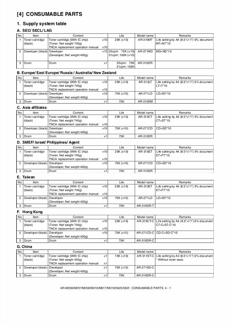
1. Supply system tableA. SEC/ SECL/ LAG
B. Europe/ East Europe/ Russia / Australia/ New Zealand
C. Asia affiliates
D. SMEF/ Israel/ Philippines/ Agent
E. Taiwan
F. Hong Kong
G. China
No. Item Content Life Model name Remarks1 Toner cartridge
(black)Toner cartridge (With IC chip)(Toner; Net weight 745g)TNCA replacement operation manual
×10
×10
25K (×10) AR-310MT Life sett ing by A4 (8 .5"×11") 6% documentMT=NT*10
2 Developer (black) Developer(Developer; Net weight 400g)
×10 25cpm: 75K (×10)31cpm: 100K (×10)
AR-271MD MD=ND*10
3 Drum Drum ×1 25cpm: 75K31cpm: 100K
AR-310DR
No. Item Content Life Model name Remarks1 Toner cartridge
(black)Toner cartridge (With IC chip)(Toner; Net weight 745g)TNCA replacement operation manual
×10
×10
25K (×10) AR-310LT Life sett ing by A4 (8 .5"×11") 6% documentLT=T*10
2 Developer (black) Developer(Developer; Net weight 400g)
×10 75K (×10) AR-271LD LD=DV*10
3 Drum Drum ×1 75K AR-310DM
No. Item Content Life Model name Remarks1 Toner cartridge(black)
Toner cartridge (With IC chip)(Toner; Net weight 745g)TNCA replacement operation manual
×10
×10
25K (×10) AR-310CT Life setting by A4 (8 .5"×11") 6% documentCT=ST*10
2 Developer (black) Developer(Developer; Net weight 400g)
×10 75K (×10) AR-271CD CD=SD*10
3 Drum Drum ×1 75K AR-310DR
No. Item Content Life Model name Remarks1 Toner cartridge
(black)Toner cartridge (With IC chip)(Toner; Net weight 745g)TNCA replacement operation manual
×10
×10
25K (×10) AR-310ET Life sett ing by A4 (8 .5"×11") 6% documentET=FT*10
2 Developer (black) Developer(Developer; Net weight 400g)
×10 75K (×10) AR-271LD LD=DV*10
3 Drum Drum ×1 75K AR-310DR-T
No. Item Content Life Model name Remarks1 Toner cartridge
(black)Toner cartridge (With IC chip)(Toner; Net weight 745g)
TNCA replacement operation manual
×10
×10
25K (×10) AR-310CT-C Life setting by A4 (8.5"×11") 6% documentCT-C=ST-C*10
2 Developer (black) Developer(Developer; Net weight 400g)
×10 75K (×10) AR-271CD-C CD-C=SD-C*10
3 Drum Drum ×1 75K AR-310DR-C
No. Item Content Life Model name Remarks1 Toner cartridge
(black)Toner cartridge (With IC chip)(Toner; Net weight 455g)TNCA replacement operation manual
×1
×1
15K (×10) AR-311ST-C Life sett ing by A4 (8.5"×11") 6% document* Without toner save.
2 Developer (black) Developer(Developer; Net weight 400g)
×1 75K (×10) AR-271SD-C
3 Drum Drum ×1 75K AR-310DR-C
8/9/2019 AR-M318 SM
http://slidepdf.com/reader/full/ar-m318-sm 16/159
8/9/2019 AR-M318 SM
http://slidepdf.com/reader/full/ar-m318-sm 17/159
AR-M256/M257/M258/M316/M317/M318/5625/5631 CONSUMABLE PARTS 4 - 3
C. STCL/ SRH/ SRS/ SRSSC/ SBI/ Agent (All model)
The other maintenance parts than the above are supplied as service parts.
No. Item Content LifeModelname
Remarks
1 Upper heat roller kit Upper heat rollerFuser gearUpper heat roller bearingUpper cleaning padFusing separation pawl (upper)
×1×1×2×1×4
150K AR-310UH
2 Lower heat roller kit Lower heat rollerFusing separation pawl (lower)Fuser bearing (lower)
×1×4×2
300K AR-310LH
3 150K maintenancekit
Drum separation pawl unitTransfer roller unitDV bladeDV side sheet N
×2×1×1×2
150K AR-310KA
4 MC unit MC unit ×10 25cpm: 75K (×10)31cpm: 100K (×10)
AR-310MC AR-310MC = AR-310NC ×10The order places an order in AR-310MC.Addition of Sterling.
5 Cleaner blade Cleaner blade ×10 25cpm: 75K (×10)31cpm: 100K (×10)
AR-270CB AR-270CB = AR-270BL ×10The order places an order in AR-270CB.
6 Drum frame unit Drum frame unit ×1 25cpm: 225K31cpm: 300K
AR-310DU The life of the toner reception seat attached tothe drum frame is 225K (25cpm)/ 300K(31cpm), and it can be used up to 3 times.(Supplied as a drum frame unit.)
Drum frame unit contains all the drum unitparts excluding Drum and Drum fixing plate.
4 Staple cartridge Staple cartridge ×3 3000 staples ×3 AR-SC1 For AR-FN5A (For 30 sheets staple)Common with the cartridge for FN4
5 Staple cartridge Staple cartridge ×3 5000 staples ×3 AR-SC2 For AR-F14N (For 50 sheets staple)Common with the cartridge for FN7
8/9/2019 AR-M318 SM
http://slidepdf.com/reader/full/ar-m318-sm 18/159
AR-M256/M257/M258/M316/M317/M318/5625/5631 CONSUMABLE PARTS 4 - 4
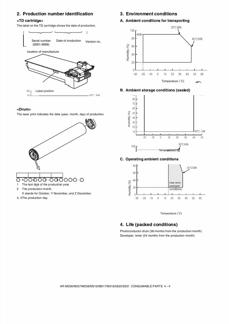
2. Production number identification<TD cartridge>The label on the TD car tridge shows the date of production.
<Drum>The laser print indicates the date (year, month, day) of production.
1 The last digit of the production year.2 The production month.
X stands for October, Y November, and Z December.3, 4The production day.
3. Environment conditionsA. Ambient conditions for transporting
B. Ambient storage conditions (sealed)
C. Operating ambient conditions
4. Life (packed conditions)Photoconductor drum (36 months from the production month)Developer, toner (24 months from the production month)
1 2 3 4
Label position
Serial number(0001-9999)
Version no.Date of oroduction
location of manufacture
Temperature (˚C)
H u m
i d i t y ( % )
Temperature (˚C)
H u m
i d i t y ( %
)
Use envi-ronmentconditions
H u m
i d i t y ( % )
Temperature (˚C)
8/9/2019 AR-M318 SM
http://slidepdf.com/reader/full/ar-m318-sm 19/159
AR-M256/M257/M258/M316/M317/M318/5625/5631 UNPACKING AND INSTALLATION 5 - 1
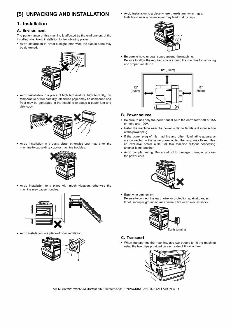
[5] UNPACKING AND INSTALLATION
1. InstallationA. EnvironmentThe performance of this machine is affected by the environment of theinstalling site. Avoid installation to the following places:• Avoid installation in direct sunlight, otherwise the plastic parts may
be deformed.
• Avoid installation in a place of high temperature, high humidity, lowtemperature or low humidity, otherwise paper may be dampened andfrost may be generated in the machine to cause a paper jam anddirty copy.
• Avoid installation in a dusty place, otherwise dust may enter themachine to cause dirty copy or machine troubles.
• Avoid installation to a place with much vibration, otherwise themachine may cause troubles.
• Avoid installation to a place of poor ventilation.
• Avoid installation to a place where there is ammonium gas.Installation near a diazo-copier may lead to dirty copy.
• Be sure to have enough space around the machine.Be sure to allow the required space around the machine for serv icingand proper ventilation.
B. Power source• Be sure to use only the power outlet (with the earth terminal) of 15A
or more and 100V.• Install the machine near the power outlet to facilitate disconnection
of the power plug.• If the power plug of this machine and other illuminating apparatus
are connected to the same power outlet, the lamp may flicker. Usean exclusive power outlet for this machine without connectinganother lamp together.
• Avoid complex wiring. Be careful not to damage, break, or processthe power cord.
• Earth wire connectionBe sure to connect the earth wire for protection against danger.If not, improper grounding may cause a fire or an electric shock.
C. Transport• When transporting the machine, use two people to lift the machine
using the two grips provided on each side of the machine.
12" (30cm)
12"(30cm)
12"(30cm)
Earth terminal
8/9/2019 AR-M318 SM
http://slidepdf.com/reader/full/ar-m318-sm 20/159
AR-M256/M257/M258/M316/M317/M318/5625/5631 UNPACKING AND INSTALLATION 5 - 2
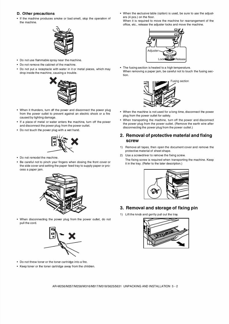
D. Other precautions• If the machine produces smoke or bad smell, stop the operation of
the machine.
• Do not use flammable spray near the machine.• Do not remove the cabinet of the machine.• Do not put a receptacle with water in it or metal pieces, which may
drop inside the machine, causing a trouble.
• When it thunders, turn off the power and disconnect the power plug
from the power outlet to prevent against an electric shock or a firecaused by lighting damage.
• If a piece of metal or water enters the machine, turn off the powerand disconnect the power plug from the power outlet.
• Do not touch the power plug with a wet hand.
• Do not remodel the machine.• Be careful not to pinch your fingers when closing the front cover or
the side cover and setting the paper feed tray to supply paper or pro-
cess a paper jam.
• When disconnecting the power plug from the power outlet, do notpull the cord.
• Do not throw toner or the toner cartridge into a fire.• Keep toner or the toner cartridge away from the children.
• When the exclusive table (option) is used, be sure to use the adjust-ers (4 pcs.) on the floor.When it is required to move the machine for rearrangement of theoffice, etc., release the adjuster locks and move the machine.
• The fusing section is heated to a high temperature.When removing a paper jam, be careful not to touch the fusing sec-tion.
• When the machine is not used for a long time, disconnect the powerplug from the power outlet for safety.
• When transporting the machine, turn off the power and disconnectthe power plug from the power outlet. (Remove the earth wire afterdisconnecting the power plug from the power outlet.)
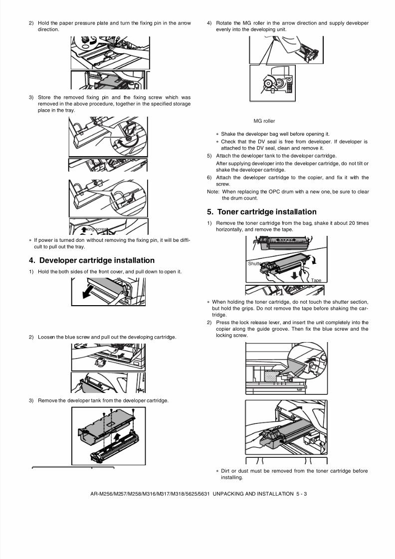
2. Removal of protective material and fixingscrew
1) Remove all tapes, then open the document cover and remove theprotective material of sheet shape.
2) Use a screwdriver to remove the fixing screw.The fixing screw is required when transporting the machine. Keepit in the tray. (Refer to the later description.)
3. Removal and storage of fixing pin1) Lift the knob and gently pull out the tray.
Lock
Adjuster
Release
Fusing section
8/9/2019 AR-M318 SM
http://slidepdf.com/reader/full/ar-m318-sm 21/159
AR-M256/M257/M258/M316/M317/M318/5625/5631 UNPACKING AND INSTALLATION 5 - 3
2) Hold the paper pressure plate and turn the fixing pin in the arrowdirection.
3) Store the removed fixing pin and the fixing screw which wasremoved in the above procedure, together in the specified storageplace in the tray.
If power is turned don without removing the fixing pin, it will be diffi-cult to pull out the tray.
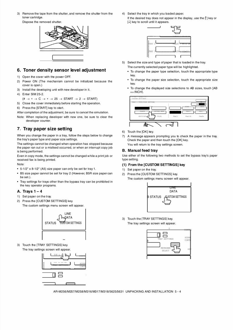
4. Developer cartridge installation1) Hold the both sides of the front cover, and pull down to open it.
2) Loosen the blue screw and pull out the developing cartridge.
3) Remove the developer tank from the developer cartridge.
4) Rotate the MG roller in the arrow direction and supply developerevenly into the developing unit.
Shake the developer bag well before opening it.Check that the DV seal is free from developer. If developer isattached to the DV seal, clean and remove it.
5) Attach the developer tank to the developer cartridge.After supplying developer into the developer cartridge, do not tilt orshake the developer cartridge.
6) Attach the developer cartridge to the copier, and fix it with thescrew.
Note: When replacing the OPC drum with a new one, be sure to clearthe drum count.
5. Toner cartridge installation1) Remove the toner cartridge from the bag, shake it about 20 times
horizontally, and remove the tape.
When holding the toner cartridge, do not touch the shutter section,but hold the grips. Do not remove the tape before shaking the car-tridge.
2) Press the lock release lever, and insert the unit completely into thecopier along the guide groove. Then fix the blue screw and thelocking screw.
Dirt or dust must be removed from the toner cartridge beforeinstalling.
Fixing pin
Fixing screw
MG roller
Tape
Shutter
Shake about 20 times.
8/9/2019 AR-M318 SM
http://slidepdf.com/reader/full/ar-m318-sm 22/159
AR-M256/M257/M258/M316/M317/M318/5625/5631 UNPACKING AND INSTALLATION 5 - 4
3) Remove the tape from the shutter, and remove the shutter from thetoner cartridge.Dispose the removed shutter.
6. Toner density sensor level adjustment1) Open the cover with the power OFF.2) Power ON (The mechanism cannot be initialized because the
cover is open.)3) Install the developing unit with new developer in it.4) Enter SIM 25-2.
(# → → C → → 25 → START → 2 → START)5) Close the cover immediately before starting the operation.6) Press the [START] key to start.After completion of the adjustment, be sure to cancel the simulation.Note: When replacing developer with new one, be sure to clear the
developer counter.
7. Tray paper size settingWhen you change the paper in a tray, follow the steps below to changethe tray's paper type and paper size settings.The settings cannot be changed when operation has stopped becausethe paper ran out or a misfeed occurred, or when an interrupt copy jobis being performed.Even in copy mode, the settings cannot be changed while a print job orreceived fax is being printed.Note:• 5-1/2" x 8-1/2" (A5) size paper can only be set for tray 1.
• B5 size paper cannot be set for tray 2 (However, B5R size paper canbe set.).
• Tray settings for trays other than the bypass tray can be prohibited inthe key operator programs.
A. Trays 1 – 41) Set paper on the tray.2) Press the [CUSTOM SETTINGS] key.
The custom settings menu screen will appear.
3) Touch the [TRAY SETTINGS] key.The tray settings screen will appear.
4) Select the tray in which you loaded paper.If the desired tray does not appear in the display, use the [ ↑] key or[↓] key to scroll until it appears.
5) Select the size and type of paper that is loaded in the tray.The currently selected paper type will be highlighted.• To change the paper type selection, touch the appropriate type
key.• To change the paper size selection, touch the appropriate size
key.• To change the displayed size selections to AB sizes, touch [AB
↔ INCH].
6) Touch the [OK] key.7) A message appears prompting you to check the paper in the tray.
Check the paper and then touch the [OK] key.You will return to the tray settings screen.
B. Manual feed trayUse either of the following two methods to set the bypass tray's papertype setting.
(1) From the [CUSTOM SETTINGS] key1) Set paper on the tray.
2) Press the [CUSTOM SETTINGS] key.The custom settings menu screen will appear.
3) Touch the [TRAY SETTINGS] key.The tray settings screen will appear.
DATALINE
STATUS CUSTOM SETTINGS
TOT L COUNT
TRAY SETTINGSADDRECONTR
KEYBOARDSELECT
KEY
CONTR
TRAY 1
TRAY 2
TRAY 3
PLAIN / 8½ x 14
PLAIN / 11x17
TYPE / SIZE
PLAIN / 8½ x 11
CUSTOM SETTINGS
TRAY 1 TYPE/SIZE SETTING
TYPE
RECYCLED
PLAIN
COLOR
LETTER HEAD 11x17
8½x11
8½x14
8½x11R 5½x8½
8½x13
OK
SIZE AB INCH
DATALINE
B STATUS CUSTOM SETTINGS
U
TRAY SETTINGSADDRECONTR
KEYBOARDSELECT
KEY
CONTRA
8/9/2019 AR-M318 SM
http://slidepdf.com/reader/full/ar-m318-sm 23/159
AR-M256/M257/M258/M316/M317/M318/5625/5631 UNPACKING AND INSTALLATION 5 - 5
4) Touch the [BYPASS TRAY] key.
5) Select the type of paper that is loaded in the tray.
"JAPANESE P/C" refers to official postcards used in Japan.
6) Touch the [OK] key.You will return to the tray settings screen.
(2) From the [PAPER SELECT] key1) Set paper on the tray.
2) Touch the [PAPER SELECT] key.
3) Touch the paper type selection key.
4) Select the paper type."JAPANESE P/C" refers to official postcards used in Japan.
5) Touch the [PAPER SELECT] key.You will return to the main screen of copy mode.
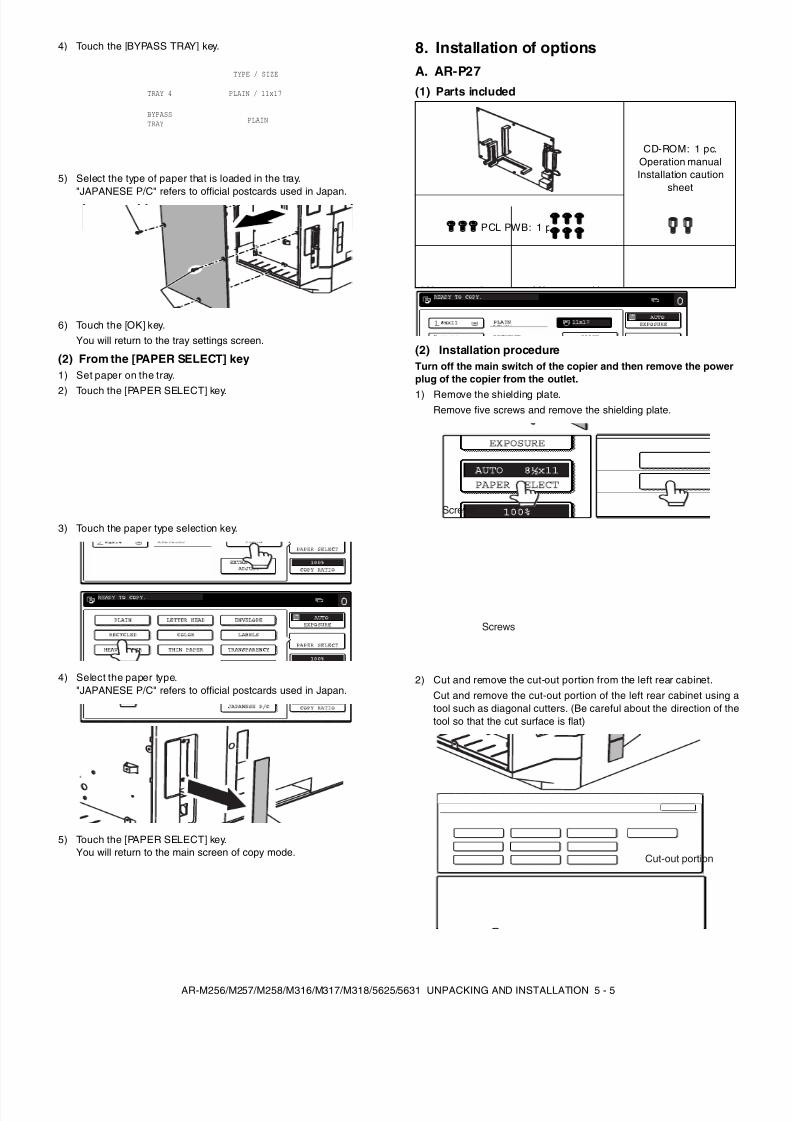
8. Installation of optionsA. AR-P27(1) Parts included
(2) Installation procedureTurn off the main switch of the copier and then remove the powerplug of the copier from the outlet.
1) Remove the shielding plate.Remove five screws and remove the shielding plate.
2) Cut and remove the cut-out portion from the left rear cabinet.Cut and remove the cut-out portion of the left rear cabinet using atool such as diagonal cutters. (Be careful about the direction of thetool so that the cut surface is flat)
TRAY 4
BYPASSTRAY
TYPE / SIZE
PLAIN
PLAIN / 11x17
CUSTOM SETTINGS
BYPASS TRAY TYPE SETTING
SELECT THE PAPER TYPE.
RECYCLED
PLAIN
COLOR
HEAVY PAPER THIN PAPER
LETTER HEAD
LABELS
TRANSPARENCY
ENVELOPE JAPANESE P/C
OK
CD-ROM: 1 pc.Operation manualInstallation caution
sheet
PCL PWB: 1 pc.
M3 screws: 3 pcs.(For installation of
the parallel and theUSB connectors)
M3 screws withspring washer: 6 pcs.(For installation of the
PCL PWB)
Support post: 2 pcs.
Screws
Screws
Cut-out portion
8/9/2019 AR-M318 SM
http://slidepdf.com/reader/full/ar-m318-sm 24/159
AR-M256/M257/M258/M316/M317/M318/5625/5631 UNPACKING AND INSTALLATION 5 - 6
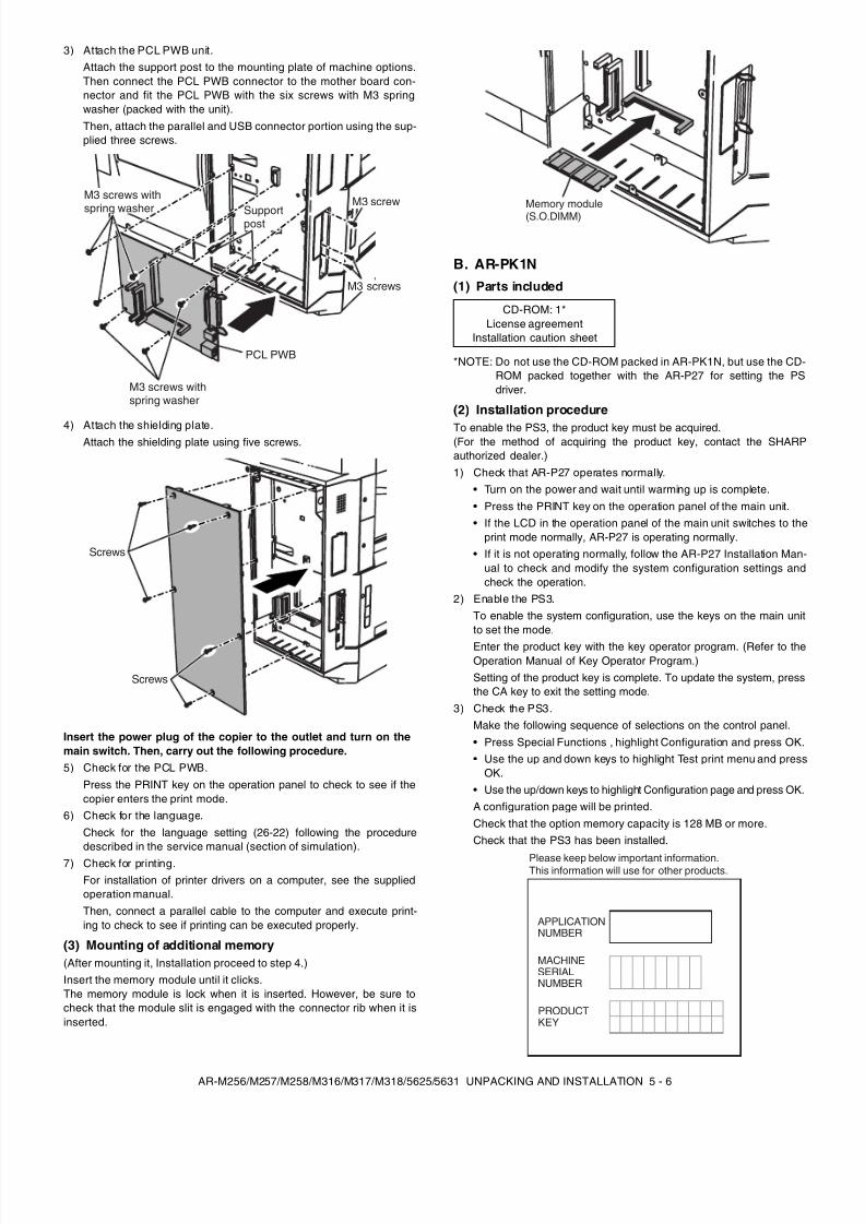
3) Attach the PCL PWB unit.Attach the support post to the mounting plate of machine options.Then connect the PCL PWB connector to the mother board con-nector and fit the PCL PWB with the six screws with M3 springwasher (packed with the unit).Then, attach the parallel and USB connector portion using the sup-plied three screws.
4) Attach the shielding plate.Attach the shielding plate using five screws.
Insert the power plug of the copier to the outlet and turn on themain switch. Then, carry out the following procedure.5) Check for the PCL PWB.
Press the PRINT key on the operation panel to check to see if thecopier enters the print mode.
6) Check for the language.Check for the language setting (26-22) following the proceduredescribed in the service manual (section of simulation).
7) Check for printing.For installation of printer drivers on a computer, see the suppliedoperation manual.Then, connect a parallel cable to the computer and execute print-ing to check to see if printing can be executed properly.
(3) Mounting of additional memory(After mounting it, Installation proceed to step 4.)Insert the memory module until it clicks.The memory module is lock when it is inserted. However, be sure tocheck that the module slit is engaged with the connector rib when it isinserted.
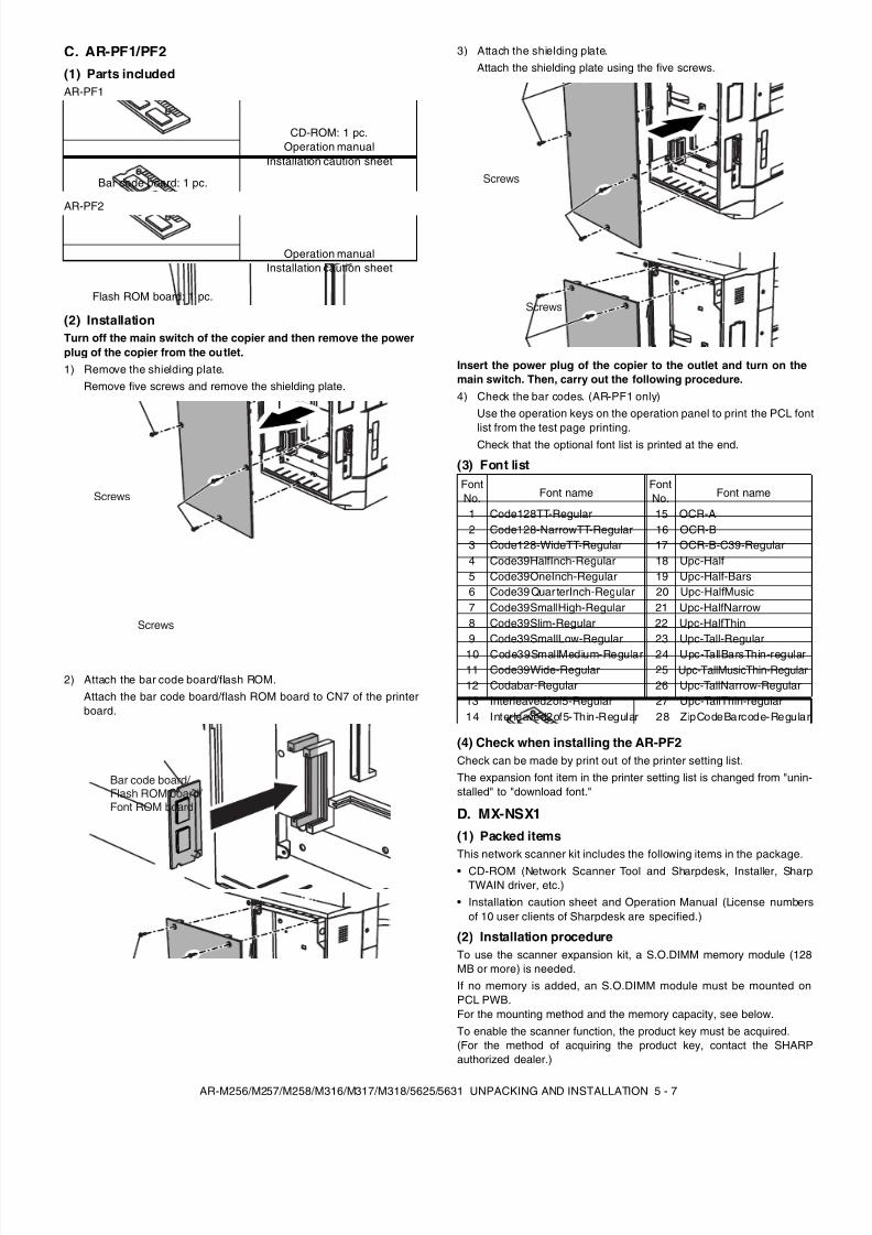
B. AR-PK1N(1) Parts included
*NOTE: Do not use the CD-ROM packed in AR-PK1N, but use the CD-ROM packed together with the AR-P27 for setting the PSdriver.
(2) Installation procedure
To enable the PS3, the product key must be acquired.(For the method of acquiring the product key, contact the SHARPauthorized dealer.)1) Check that AR-P27 operates normally.
• Turn on the power and wait until warming up is complete.• Press the PRINT key on the operation panel of the main unit.• If the LCD in the operation panel of the main unit switches to the
print mode normally, AR-P27 is operating normally.• If it is not operating normally, follow the AR-P27 Installation Man-
ual to check and modify the system configuration settings andcheck the operation.
2) Enable the PS3.To enable the system configuration, use the keys on the main unitto set the mode.
Enter the product key with the key operator program. (Refer to theOperation Manual of Key Operator Program.)Setting of the product key is complete. To update the system, pressthe CA key to exit the setting mode.
3) Check the PS3.Make the following sequence of selections on the control panel.• Press Special Functions , highlight Configuration and press OK.• Use the up and down keys to highlight Test print menu and press
OK.• Use the up/down keys to highlight Configuration page and press OK.A configuration page will be printed.Check that the option memory capacity is 128 MB or more.Check that the PS3 has been installed.
Supportpost
PCL PWB
M3 screws with
spring washerM3 screw
M3 screws
M3 screws withspring washer
Screws
Screws
CD-ROM: 1*License agreement
Installation caution sheet
Memory module(S.O.DIMM)
APPLICATIONNUMBER
MACHINESERIALNUMBER
PRODUCTKEY
Please keep below important information.This information will use for other products.
8/9/2019 AR-M318 SM
http://slidepdf.com/reader/full/ar-m318-sm 25/159
AR-M256/M257/M258/M316/M317/M318/5625/5631 UNPACKING AND INSTALLATION 5 - 7
C. AR-PF1/PF2(1) Parts includedAR-PF1
AR-PF2
(2) InstallationTurn off the main switch of the copier and then remove the powerplug of the copier from the outlet.1) Remove the shielding plate.
Remove five screws and remove the shielding plate.
2) Attach the bar code board/flash ROM.Attach the bar code board/flash ROM board to CN7 of the printerboard.
3) Attach the shielding plate.Attach the shielding plate using the five screws.
Insert the power plug of the copier to the outlet and turn on themain switch. Then, carry out the following procedure.4) Check the bar codes. (AR-PF1 only)
Use the operation keys on the operation panel to print the PCL font
list from the test page printing.Check that the optional font list is printed at the end.
(3) Font list
(4) Check when installing the AR-PF2Check can be made by print out of the printer setting list.The expansion font item in the printer setting list is changed from "unin-stalled" to "download font."
D. MX-NSX1(1) Packed itemsThis network scanner kit includes the following items in the package.• CD-ROM (Network Scanner Tool and Sharpdesk, Installer, Sharp
TWAIN driver, etc.)• Installation caution sheet and Operation Manual (License numbers
of 10 user clients of Sharpdesk are specified.)
(2) Installation procedureTo use the scanner expansion kit, a S.O.DIMM memory module (128MB or more) is needed.If no memory is added, an S.O.DIMM module must be mounted onPCL PWB.For the mounting method and the memory capacity, see below.To enable the scanner function, the product key must be acquired.(For the method of acquiring the product key, contact the SHARPauthorized dealer.)
CD-ROM: 1 pc.Operation manual
Installation caution sheet
Bar code board: 1 pc.
Operation manualInstallation caution sheet
Flash ROM board: 1 pc.
Screws
Screws
Bar code board/ Flash ROM board/ Font ROM board
FontNo. Font name
FontNo. Font name
1 Code128TT-Regular 15 OCR-A2 Code128-NarrowTT-Regular 16 OCR-B3 Code128-WideTT-Regular 17 OCR-B-C39-Regular4 Code39HalfInch-Regular 18 Upc-Half5 Code39OneInch-Regular 19 Upc-Half-Bars6 Code39 Quar terInch-Regular 20 Upc-HalfMusic7 Code39SmallHigh-Regular 21 Upc-HalfNarrow8 Code39Slim-Regular 22 Upc-HalfThin9 Code39SmallLow-Regular 23 Upc-Tall-Regular
10 Code39SmallMedium-Regular 24 Upc-TallBarsThin-regular11 Code39Wide-Regular 25 Upc-TallMusicThin-Regular12 Codabar-Regular 26 Upc-TallNarrow-Regular13 Interleaved2of5-Regular 27 Upc-TallThin-regular14 Interleaved2of5-Thin-Regular 28 ZipCodeBarcode-Regular
Screws
Screws
8/9/2019 AR-M318 SM
http://slidepdf.com/reader/full/ar-m318-sm 26/159
AR-M256/M257/M258/M316/M317/M318/5625/5631 UNPACKING AND INSTALLATION 5 - 8
1) Check the capacity of the Printer PWB memory.Use the keys of the copier to pr int the configuration page.(For details, see the operation manual.)Check that the capacity of the optional memory is 128 MB or more.
2) Enable the network scanner feature.To enable the system configuration, use the keys on the copier toset the mode.Enter the product key with the key operator program.(Refer to the Operation Manual of Key Operator Program.)Setting of the product key is completed. Press the [EXIT] key toupdate the system and exit the setting mode.
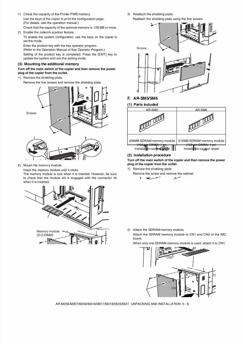
(3) Mounting the additional memoryTurn off the main switch of the copier and then remove the powerplug of the copier from the outlet.1) Remove the shielding plate.
Remove the five screws and remove the shielding plate.
2) Mount the memory module.Insert the memory module until it clicks.The memory module is lock when it is inserted. However, be sureto check that the module slit is engaged with the connector ribwhen it is inserted.
3) Reattach the shielding plate.Reattach the shielding plate using the five screws.
F. AR-SM5/SM6(1) Parts included
(2) Installation procedureTurn off the main switch of the copier and then remove the powerplug of the copier from the outlet.1) Remove the shielding plate.
Remove the screw and remove the cabinet.
2) Attach the SDRAM memory module.Attach the SDRAM memory module to CN1 and CN2 of the IMCboard.When only one SDRAM memory module is used, attach it to CN1.
Screws
Screws
Memory module(S.O.DIMM)
AR-SM5 AR-SM6
256MB SDRAM memory module(168 pin DIMM): 1 pc.
Installation caution sheet
512MB SDRAM memory module(168 pin DIMM): 1 pc.
Installation caution sheet
Screws
Screws
CN1
CN2
8/9/2019 AR-M318 SM
http://slidepdf.com/reader/full/ar-m318-sm 27/159
8/9/2019 AR-M318 SM
http://slidepdf.com/reader/full/ar-m318-sm 28/159
8/9/2019 AR-M318 SM
http://slidepdf.com/reader/full/ar-m318-sm 29/159
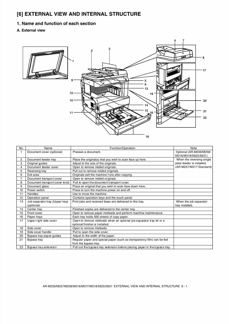
AR-M256/M257/M258/M316/M317/M318/5625/5631 EXTERNAL VIEW AND INTERNAL STRUCTURE 6 - 3
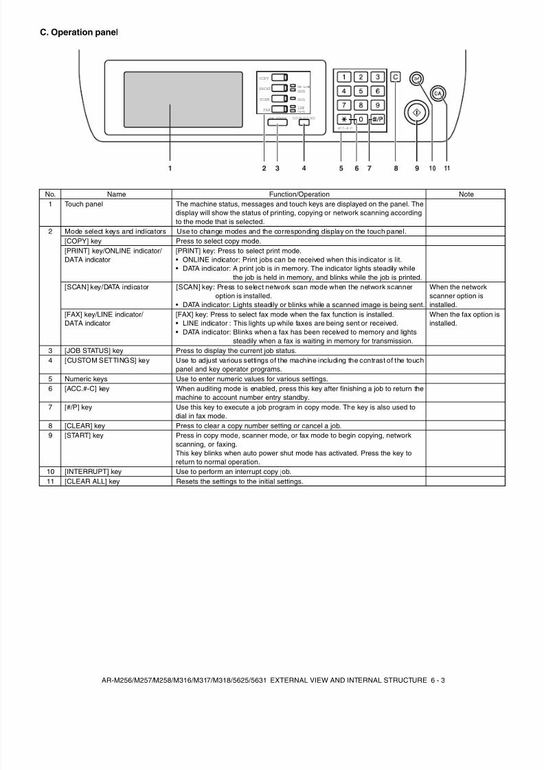
C. Operation panel
No. Name Function/Operation Note1 Touch panel The machine status, messages and touch keys are displayed on the panel. The
display will show the status of printing, copying or network scanning accordingto the mode that is selected.
2 Mode select keys and indicators Use to change modes and the corresponding display on the touch panel.[COPY] key Press to select copy mode.[PRINT] key/ONLINE indicator/ DATA indicator
[PRINT] key: Press to select print mode.• ONLINE indicator: Print jobs can be received when this indicator is lit.
• DATA indicator: A print job is in memory. The indicator lights steadily whilethe job is held in memory, and blinks while the job is printed.
[SCAN] key/DATA indicator [SCAN] key: Press to select network scan mode when the network scanneroption is installed.
• DATA indicator: Lights steadily or blinks while a scanned image is being sent.
When the networkscanner option isinstalled.
[FAX] key/LINE indicator/ DATA indicator
[FAX] key: Press to select fax mode when the fax function is installed.• LINE indicator : This lights up while faxes are being sent or received.• DATA indicator: Blinks when a fax has been received to memory and lights
steadily when a fax is waiting in memory for transmission.
When the fax option isinstalled.
3 [JOB STATUS] key Press to display the current job status.4 [CUSTOM SETTINGS] key Use to adjust various settings of the machine including the contrast of the touch
panel and key operator programs.5 Numeric keys Use to enter numeric values for various settings.6 [ACC.#-C] key When auditing mode is enabled, press this key after finishing a job to return the
machine to account number entry standby.7 [#/P] key Use this key to execute a job program in copy mode. The key is also used to
dial in fax mode.8 [CLEAR] key Press to clear a copy number setting or cancel a job.9 [START] key Press in copy mode, scanner mode, or fax mode to begin copying, network
scanning, or faxing.This key blinks when auto power shut mode has activated. Press the key toreturn to normal operation.
10 [INTERRUPT] key Use to perform an interrupt copy job.11 [CLEAR ALL] key Resets the settings to the initial settings.
COPY
SCAN
FAX
ON LI NE
DATA
DATA
DATA
LINE
JOB STATUS CUSTOM SETTINGS
AC C.#-C
9 10 112 3 4 5 6 7 81
8/9/2019 AR-M318 SM
http://slidepdf.com/reader/full/ar-m318-sm 30/159
8/9/2019 AR-M318 SM
http://slidepdf.com/reader/full/ar-m318-sm 31/159
AR-M256/M257/M258/M316/M317/M318/5625/5631 EXTERNAL VIEW AND INTERNAL STRUCTURE 6 - 5
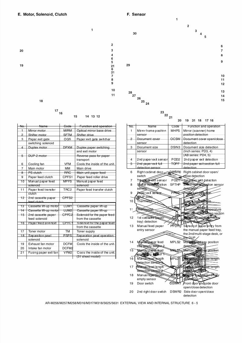
E. Motor, Solenoid, Clutch F. Sensor
No. Name Code Function and operation1 Mirror motor MIRM Optical mirror base drive2 Shifter motor SFTM Shifter drive3 Paper exit gate
switching solenoidOGS Paper exit gate switcher
4 Duplex motor DPXM Duplex paper switchingand exit motor
5 DUP-2 motor Reverse pass for papertransport
6 Cooling fan VFM Cools the inside of the unit.7 Main motor MM Main drive8 PS clutch RRC Main unit paper feed9 Paper feed clutch CPFS1 Paper feed roller drive
10 Manual paper feedsolenoid
MPFS Manual paper feedsolenoid
11 Paper feed transferclutch
TRC2 Paper feed transfer clutch
12 2nd cassette paperfeed clutch
CPFS2
13 Cassette lift-up mo tor LUM1 Cassette paper lift-up14 Cassette lift-up mo tor LUM2 Cassette paper lift-up15 2nd cassette paper
feed solenoidCPFC2 Solenoid for the paper feed
from the cassette16 Paper feed so leno id CPFC1 Soleno id for the paper feed
from the cassette17 Toner motor TM Toner supply18 Separation pawl
solenoid
PSPS Separation pawl operation
solenoid19 Exhaust fan motor DCFM Cools the inside of the unit.20 Intake fan motor DCFM221 Fusing paper exit fan VFM2 Cools the inside of the unit.
(31 sheet model)
1
2
6
6
34
5
789
10
11
19
20
1213141516
17
18
21
21
No. Name Code Function and operation1 Mirror home posit ion
sensorMHPS Mirror (scanner) home
position detection2 Document cover
sensorOCSW Document cover open/close
detection3 Document size
sensorDSIN3 Document size detection
(Inch series: PD3, 4)(AB series: PD4, 5)
4 2nd paper ex it sensor POD2 2nd paper ex it detection5 2nd paper ex it fu ll
detection sensorTOPF 2nd paper exit section full
detection6 Righ t cabinet door
switchDSWR0 Right cabinet door open/
close detection
7 1st paper exit sensor POD1 1st paper ex it detection8 Shifter home position
sensorSFTHP Shifter home position sensor
detection9 Paper ex it sensor
(DUP side)PPD2 Paper exit detection
10 Thermistor Fusing temperaturedetection
11 Thermostat Abnormal high temperaturedetection in the fusing section
12 1st cassette (papertray) detection
CD1 1st cassette (paper tray)empty detection
13 Manual feed paperentry sensor
PPD1L Sensor of paper entry fromthe manual paper feed tray,the 2nd/multi-stage desk, orthe DUP
14 Manual paper feedtray empty sensor 2
MPLS2 Manual feed tray positiondetection
15 Manual paper feedtray empty sensor 1
MPLS1 Manual feed tray positiondetection
16 Manual feed lengthdetection sensor 1
MPLD1 Manual feed paper lengthdetection
17 Manual feed lengthdetection sensor 2
MPLD2 Manual feed paper lengthdetection
18 Manual feed paperempty sensor
MPED Manual feed paper emptydetection
19 Door switch DSWR1 Front door and side dooropen/close detection
20 2nd right door switch DSWR2 Side door open/closedetection
1
2
3
678
9
12
1415
16171831192021
2223
2425
2627
28 13
29
30
10
45
11
8/9/2019 AR-M318 SM
http://slidepdf.com/reader/full/ar-m318-sm 32/159
AR-M256/M257/M258/M316/M317/M318/5625/5631 EXTERNAL VIEW AND INTERNAL STRUCTURE 6 - 6
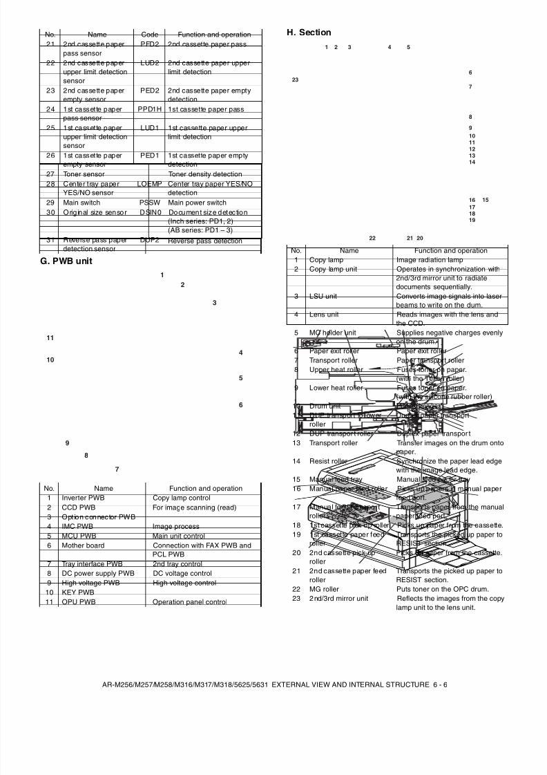
G. PWB unit
H. Section21 2nd cassette paper
pass sensorPFD2 2nd cassette paper pass
22 2nd cassette paperupper limit detectionsensor
LUD2 2nd cassette paper upperlimit detection
23 2nd cassette paperempty sensor
PED2 2nd cassette paper emptydetection
24 1st cassette paperpass sensor
PPD1H 1st cassette paper pass
25 1st cassette paperupper limit detectionsensor
LUD1 1st cassette paper upperlimit detection
26 1st cassette paperempty sensor
PED1 1st cassette paper emptydetection
27 Toner sensor Toner density detection28 Center tray paper
YES/NO sensorLOEMP Center tray paper YES/NO
detection29 Main switch PSSW Main power switch30 Orig inal size sensor DSIN0 Document size detection
(Inch series: PD1, 2)(AB series: PD1 – 3)
31 Reverse pass paperdetection sensor
DUP2 Reverse pass detection
No. Name Function and operation1 Inverter PWB Copy lamp control2 CCD PWB For image scanning (read)3 Opt ion connector PWB4 IMC PWB Image process5 MCU PWB Main unit control6 Mother board Connection with FAX PWB and
PCL PWB7 Tray interface PWB 2nd tray control8 DC power supply PWB DC voltage control9 High voltage PWB High voltage control
10 KEY PWB11 OPU PWB Operation panel control
No. Name Code Function and operation
1
2
3
4
5
6
7
8
9
10
11
No. Name Function and operation1 Copy lamp Image radiation lamp
2 Copy lamp unit Operates in synchronization with2nd/3rd mirror unit to radiatedocuments sequentially.
3 LSU unit Converts image signals into laserbeams to write on the dum.
4 Lens unit Reads images with the lens andthe CCD.
5 MC holder unit Supplies negative charges evenlyon the drum.
6 Paper exit roller Paper exit roller7 Transport roller Paper transport roller8 Upper heat roller Fuses toner on paper.
(with the Teflon roller)9 Lower heat roller Fuses toner on paper.
(with the silicone rubber roller)
10 Drum unit Forms images.11 DUP transport follower
rollerDuplex paper transport
12 DUP transpor t roller Duplex paper transpor t13 Transport roller Transfer images on the drum onto
paper.14 Resist roller Synchronize the paper lead edge
with the image lead edge.15 Manual feed tray Manual feed paper tray16 Manual paper feed roller Picks up papers in manual paper
feed port.17 Manual feed transport
rollerTransports paper from the manualpaper feed port.
18 1st cassette pick-up roller Picks up paper from the cassette.19 1st cassette paper feed
roller
Transports the picked up paper to
RESIST section.20 2nd cassette pick-up
rollerPicks up paper from the cassette.
21 2nd cassette paper feedroller
Transports the picked up paper toRESIST section.
22 MG roller Puts toner on the OPC drum.23 2 nd/3rd mirror unit Reflects the images from the copy
lamp unit to the lens unit.
1 2 3 4 5
6
7
8
9
1011121314
16171819
15
202122
23
8/9/2019 AR-M318 SM
http://slidepdf.com/reader/full/ar-m318-sm 33/159
AR-M256/M257/M258/M316/M317/M318/5625/5631 ADJUSTMENTS, SETTING 7 - 1
[7] ADJUSTMENTS, SETTING
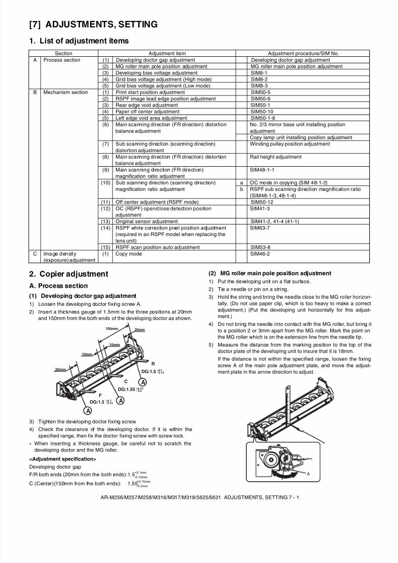
1. List of adjustment items
2. Copier adjustmentA. Process section
(1) Developing doctor gap adjustment1) Loosen the developing doctor fixing screw A.2) Insert a thickness gauge of 1.5mm to the three positions at 20mm
and 150mm from the both ends of the developing doctor as shown.
3) Tighten the developing doctor fixing screw.4) Check the clearance of the developing doctor. If it is within the
specified range, then fix the doctor fixing screw with screw lock.When inserting a thickness gauge, be careful not to scratch thedeveloping doctor and the MG roller.
<Adjustment specification>
(2) MG roller main pole position adjustment1) Put the developing unit on a flat surface.2) Tie a needle or pin on a string.
3) Hold the string and bring the needle close to the MG roller horizon-tally. (Do not use paper clip, which is too heavy to make a correctadjustment.) (Put the developing unit horizontally for this adjust-ment.)
4) Do not bring the needle into contact with the MG roller, but bring itto a position 2 or 3mm apart from the MG roller. Mark the point onthe MG roller which is on the extension line from the needle tip.
5) Measure the distance from the marking position to the top of thedoctor plate of the developing unit to insure that it is 18mm.If the distance is not within the specified range, loosen the fixingscrew A of the main pole adjustment plate, and move the adjust-ment plate in the arrow direction to adjust.
Section Adjustment item Adjustment procedure/SIM No.A Process section (1) Developing doctor gap adjustment Developing doctor gap adjustment
(2) MG roller main pole position adjustment MG roller main pole position adjustment(3) Developing bias voltage adjustment SIM8-1(4) Grid bias voltage adjustment (High mode) SIM8-2(5) Grid bias voltage adjustment (Low mode) SIM8-3
B Mechanism section (1) Print start position adjustment SIM50-5
(2) RSPF image lead edge position adjustment SIM50-6(3) Rear edge void adjustment SIM50-1(4) Paper off center adjustment SIM50-10(5) Left edge void area adjustment SIM50-1-8(6) Main scanning direction (FR direction) distortion
balance adjustmentNo. 2/3 mirror base unit installing positionadjustmentCopy lamp unit installing position adjustment
(7) Sub scanning direction (scanning direction)distortion adjustment
Winding pulley position adjustment
(8) Main scanning direction (FR direction) distortionbalance adjustment
Rail height adjustment
(9) Main scanning direction (FR direction)magnification ratio adjustment
SIM48-1-1
(10) Sub scanning direction (scanning direction)magnification ratio adjustment
a OC mode in copying (SIM 48-1-2)b RSPF sub scanning direction magnification ratio
(SIM48-1-3, 48-1-4)(11) Off center adjustment (RSPF mode) SIM50-12(12) OC (RSPF) open/close detection position
adjustmentSIM41-3
(13) Original sensor adjustment SIM41-2, 41-4 (41-1)(14) RSPF white correction pixel position adjustment
(required in an RSPF model when replacing thelens unit)
SIM63-7
(15) RSPF scan position auto adjustment SIM53-8C Image density
(exposure) adjustment(1) Copy mode SIM46-2
Developing doctor gapF/R both ends (20mm from the both ends):1.5 +0.1mm
-0.15mm
C (Center)(150mm from the both ends): 1.55 +0.15mm-0.2mm
20mm
10mm
150mm
10mm
20mm
F
C
R
DG:1.5 +0.1- 0.15
DG:1.5 +0.1- 0.15
DG:1.55 +0.15- 0.2
A
A
A
A
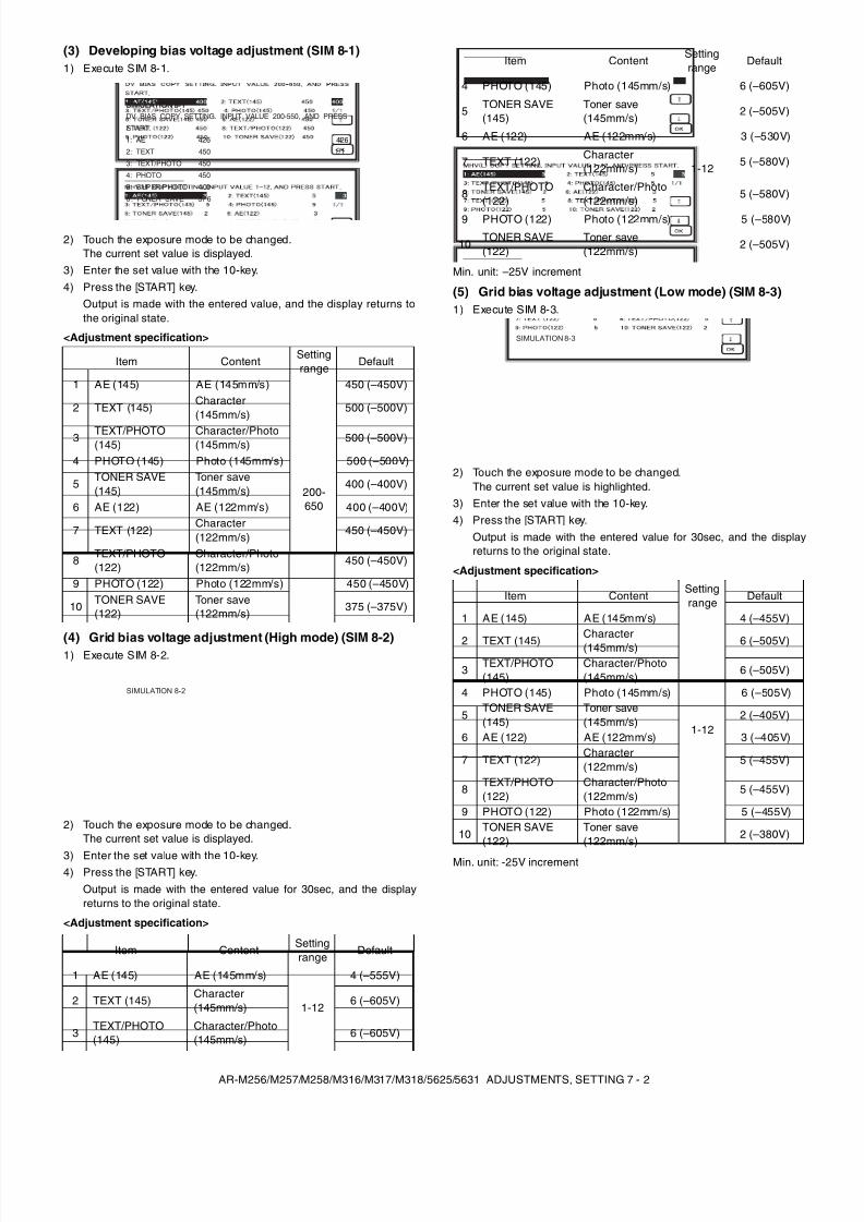
8/9/2019 AR-M318 SM
http://slidepdf.com/reader/full/ar-m318-sm 34/159
AR-M256/M257/M258/M316/M317/M318/5625/5631 ADJUSTMENTS, SETTING 7 - 2
(3) Developing bias voltage adjustment (SIM 8-1)1) Execute SIM 8-1.
2) Touch the exposure mode to be changed.The current set value is displayed.
3) Enter the set value with the 10-key.4) Press the [START] key.
Output is made with the entered value, and the display returns tothe original state.
<Adjustment specification>
(4) Grid bias voltage adjustment (High mode) (SIM 8-2)1) Execute SIM 8-2.
2) Touch the exposure mode to be changed.The current set value is displayed.
3) Enter the set value with the 10-key.4) Press the [START] key.
Output is made with the entered value for 30sec, and the displayreturns to the original state.
<Adjustment specification>
Min. unit: –25V increment
(5) Grid bias voltage adjustment (Low mode) (SIM 8-3)1) Execute SIM 8-3.
2) Touch the exposure mode to be changed.The current set value is highlighted.
3) Enter the set value with the 10-key.4) Press the [START] key.
Output is made with the entered value for 30sec, and the displayreturns to the original state.
<Adjustment specification>
Min. unit: -25V increment
Item ContentSettingrange
Default
1 AE (145) AE (145mm/s)
200-650
450 (–450V)
2 TEXT (145)Character(145mm/s)
500 (–500V)
3 TEXT/PHOTO(145)
Character/Photo(145mm/s)
500 (–500V)
4 PHOTO (145) Photo (145mm/s) 500 (–500V)
5TONER SAVE(145)
Toner save(145mm/s)
400 (–400V)
6 AE (122) AE (122mm/s) 400 (–400V)
7 TEXT (122)Character(122mm/s)
450 (–450V)
8 TEXT/PHOTO(122)
Character/Photo(122mm/s)
450 (–450V)
9 PHOTO (122) Photo (122mm/s) 450 (–450V)
10 TONER SAVE(122)
Toner save(122mm/s)
375 (–375V)
Item ContentSettingrange
Default
1 AE (145) AE (145mm/s)
1-12
4 (–555V)
2 TEXT (145)Character(145mm/s)
6 (–605V)
3TEXT/PHOTO(145)
Character/Photo(145mm/s) 6 (–605V)
SIMULATION 8-1
4261/1
DV BIAS COPY SETTING. INPUT VALUE 200-550, AND PRESS
START.
1: AE 426
2: TEXT 450
3: TEXT/PHOTO 450
4: PHOTO 450
5: SUPER/PHOTO 400
6 : TONER SAVE 37 6
SIMULATION 8-1
SIMULATION 8-2
4 PHOTO (145) Photo (145mm/s)
1-12
6 (–605V)
5 TONER SAVE(145)
Toner save(145mm/s)
2 (–505V)
6 AE (122) AE (122mm/s) 3 (–530V)
7 TEXT (122) Character(122mm/s)
5 (–580V)
8TEXT/PHOTO(122)
Character/Photo(122mm/s)
5 (–580V)
9 PHOTO (122) Photo (122mm/s) 5 (–580V)
10TONER SAVE(122)
Toner save(122mm/s)
2 (–505V)
Item ContentSettingrange
Default
1 AE (145) AE (145mm/s)
1-12
4 (–455V)
2 TEXT (145)Character(145mm/s) 6 (–505V)
3 TEXT/PHOTO(145)
Character/Photo(145mm/s)
6 (–505V)
4 PHOTO (145) Photo (145mm/s) 6 (–505V)
5TONER SAVE(145)
Toner save(145mm/s)
2 (–405V)
6 AE (122) AE (122mm/s) 3 (–405V)
7 TEXT (122)Character(122mm/s) 5 (–455V)
8TEXT/PHOTO(122)
Character/Photo(122mm/s)
5 (–455V)
9 PHOTO (122) Photo (122mm/s) 5 (–455V)
10TONER SAVE(122)
Toner save(122mm/s)
2 (–380V)
Item ContentSettingrange
Default
SIMULATION 8-3
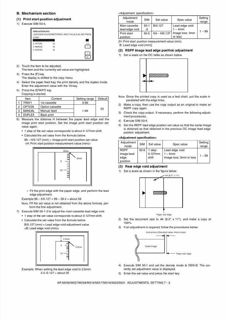
8/9/2019 AR-M318 SM
http://slidepdf.com/reader/full/ar-m318-sm 35/159
AR-M256/M257/M258/M316/M317/M318/5625/5631 ADJUSTMENTS, SETTING 7 - 3
B. Mechanism section(1) Print start position adjustment1) Execute SIM 50-5.
2) Touch the item to be adjusted.The item and the currently set value are highlighted.
3) Press the [P] key.The display is shifted to the copy menu.
4) Select the paper feed tray, the print density, and the duplex mode.Enter the adjustment value with the 10-key.
5) Press the [START] key.Copying is started.
6) Measure the distance H between the paper lead edge and theimage print start position. Set the image print start position setvalue again.• 1 step of the set value corresponds to about 0.127mm shift.• Calculate the set value from the formula below.
99 – H/0.127 (mm) = Image print start position set value <H: Print start position measurement value (mm)>
Fit the print edge with the paper edge, and perform the leadedge adjustment.
Example:99 – 5/0.127 = 99 – 39.4 = about 59Note: FIf the set value is not obtained from the above formula, per-
form the fine adjustment.7) Execute SIM 50-1-2 to adjust the main cassette lead edge void.
• 1 step of the set value corresponds to about 0.127mm shift.• Calculate the set value from the formula below.
B/0.127 (mm) = Lead edge void adjustment value<B: Lead edge void (mm)>
Example: When setting the lead edge void to 2.5mm:2.5 /0.127 = about 20
<Adjustment specification>
[H: Print start position measurement value (mm),B: Lead edge void (mm)]
(2) RSPF image lead edge position adjustment
1) Set a scale on the OC table as shown below.
Note: Since the printed copy is used as a test chart, put the scale inparalleled with the edge lines.
2) Make a copy, then use the copy output as an original to make anRSPF copy again.
3) Check the copy output. If necessary, perform the following adjust-ment procedures.
4) Execute SIM 50-6.5) Set the RSPF lead edge position set value so that the same image
is obtained as that obtained in the previous OC image lead edgeposition adjustment.
<Adjustment specification>
(3) Rear edge void adjustment1) Set a scale as shown in the figure below.
2) Set the document size to A4 (8.5" x 11"), and make a copy at
100%.3) If an adjustment is required, follow the procedures below.
4) Execute SIM 50-1 and set the density mode to DEN-B. The cur-rently set adjustment value is displayed.
5) Enter the set value and press the start key.
Item Content Setting range Default1 TRAY1 1st cassette 0-99
532 OPTION Option cassette
1-993 MANUAL Manual feed4 DUPLEX Back print
SIMULATION 50-5
531/1
LEAD EDGE ADJUSTMENT(PRINT). INPUT VALUE 0-99, AND PRESS
START.
1: TRAY1 53
2: OPTION 53
3: MANUAL 53
4: DUPLEX 53
5
10
0mm
0mm
5
10
2.5mm
2.5mm
Adjustmentmode
SIM Set value Spec valueSettingrange
Main cassettelead edge void
50-1-2
B/0.127 Lead edge void:1 – 4mmImage loss: 3mmor less
1 – 99Print startposition
50-5 99 – H/0 .127
Adjustmentmode
SIM Set value Spec valueSettingrange
RSPFimage leadedgeposition
50-6 1 step:0.127mmshift
Lead edge void:1 – 4mmImage loss: 3mm or less
1 – 99
A4 (8.5" x 11")
Paper rear edge
Void amount (Standard value: 4mm or less)
Scale image
Paper rear edge
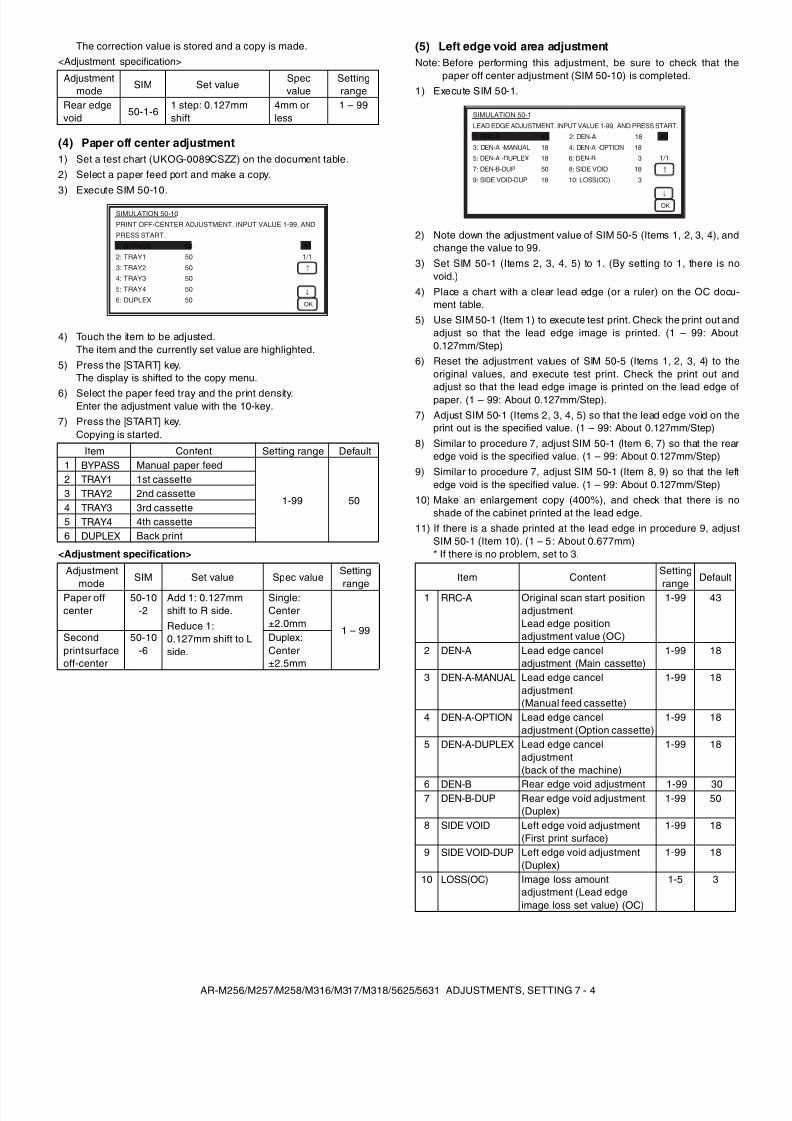
8/9/2019 AR-M318 SM
http://slidepdf.com/reader/full/ar-m318-sm 36/159
AR-M256/M257/M258/M316/M317/M318/5625/5631 ADJUSTMENTS, SETTING 7 - 4
The correction value is stored and a copy is made.<Adjustment specification>
(4) Paper off center adjustment1) Set a test chart (UKOG-0089CSZZ) on the document table.2) Select a paper feed port and make a copy.3) Execute SIM 50-10.
4) Touch the item to be adjusted.The item and the currently set value are highlighted.
5) Press the [START] key.The display is shifted to the copy menu.
6) Select the paper feed tray and the print density.Enter the adjustment value with the 10-key.
7) Press the [START] key.Copying is started.
<Adjustment specification>
(5) Left edge void area adjustmentNote: Before performing this adjustment, be sure to check that the
paper off center adjustment (SIM 50-10) is completed.1) Execute SIM 50-1.
2) Note down the adjustment value of SIM 50-5 (Items 1, 2, 3, 4), andchange the value to 99.
3) Set SIM 50-1 (Items 2, 3, 4, 5) to 1. (By setting to 1, there is novoid.)
4) Place a chart with a clear lead edge (or a ruler) on the OC docu-ment table.
5) Use SIM 50-1 (Item 1) to execute test print. Check the print out andadjust so that the lead edge image is printed. (1 – 99: About0.127mm/Step)
6) Reset the adjustment values of SIM 50-5 (Items 1, 2, 3, 4) to theoriginal values, and execute test print. Check the print out andadjust so that the lead edge image is printed on the lead edge ofpaper. (1 – 99: About 0.127mm/Step).
7) Adjust SIM 50-1 (Items 2, 3, 4, 5) so that the lead edge void on theprint out is the specified value. (1 – 99: About 0.127mm/Step)
8) Similar to procedure 7, adjust SIM 50-1 (Item 6, 7) so that the rearedge void is the specified value. (1 – 99: About 0.127mm/Step)
9) Similar to procedure 7, adjust SIM 50-1 (Item 8, 9) so that the leftedge void is the specified value. (1 – 99: About 0.127mm/Step)
10) Make an enlargement copy (400%), and check that there is noshade of the cabinet printed at the lead edge.
11) If there is a shade printed at the lead edge in procedure 9, adjustSIM 50-1 (Item 10). (1 – 5 : About 0.677mm)* If there is no problem, set to 3.
Adjustmentmode SIM Set value
Specvalue
Settingrange
Rear edgevoid 50-1-6
1 step: 0.127mmshift
4mm orless
1 – 99
Item Content Setting range Default1 BYPASS Manual paper feed
1-99 50
2 TRAY1 1st cassette3 TRAY2 2nd cassette4 TRAY3 3rd cassette5 TRAY4 4th cassette6 DUPLEX Back print
Adjustmentmode SIM Set value Spec value
Settingrange
Paper offcenter
50-10-2
Add 1: 0.127mmshift to R side.Reduce 1:0.127mm shift to Lside.
Single:Center±2.0mm
1 – 99Secondprint surfaceoff-center
50-10-6
Duplex:Center±2.5mm
SIMULATION 50-10
501/1
OK
PRINT OFF-CENTER ADJUSTMENT. INPUT VALUE 1-99, ANDPRESS START.1: BYPASS 502: TRAY1 503: TRAY2 504: TRAY3 505: TRAY4 506: DUPLEX 50
Item ContentSettingrange Default
1 RRC-A Original scan start positionadjustmentLead edge positionadjustment value (OC)
1-99 43
2 DEN-A Lead edge canceladjustment (Main cassette)
1-99 18
3 DEN-A-MANUAL Lead edge canceladjustment(Manual feed cassette)
1-99 18
4 DEN-A-OPTION Lead edge canceladjustment (Option cassette)
1-99 18
5 DEN-A-DUPLEX Lead edge canceladjustment(back of the machine)
1-99 18
6 DEN-B Rear edge void adjustment 1-99 307 DEN-B-DUP Rear edge void adjustment
(Duplex)1-99 50
8 SIDE VOID Left edge void adjustment(First print surface)
1-99 18
9 SIDE VOID-DUP Left edge void adjustment(Duplex)
1-99 18
10 LOSS(OC) Image loss amountadjustment (Lead edgeimage loss set value) (OC)
1-5 3
SIMULATION 50-1
43
1/1
OK
LEAD EDGE ADJUSTMENT. INPUT VALUE 1-99, AND PRESS START.
1: RRC-A 43 2: DEN-A 18
3: DEN-A -MANUAL 18 4: DEN-A -OPTION 18
5: DEN-A -DUPLEX 18 6: DEN-B 3
7: DEN-B-DUP 50 8: SIDE VOID 18
9: SIDE VOID-DUP 18 10: LOSS(OC) 3
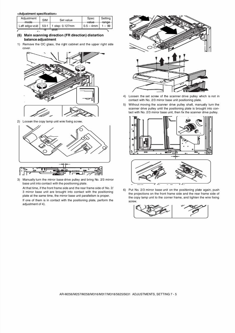
8/9/2019 AR-M318 SM
http://slidepdf.com/reader/full/ar-m318-sm 37/159
AR-M256/M257/M258/M316/M317/M318/5625/5631 ADJUSTMENTS, SETTING 7 - 5
<Adjustment specification>
(6) Main scanning direction (FR direction) distortionbalance adjustment
1) Remove the OC glass, the right cabinet and the upper right sidecover.
2) Loosen the copy lamp unit wire fixing screw.
3) Manually turn the mirror base drive pulley and bring No. 2/3 mirrorbase unit into contact with the positioning plate.At that time, if the front frame side and the rear frame side of No. 2/ 3 mirror base unit are brought into contact with the positioningplate at the same time, the mirror base unit parallelism is proper.If one of them is in contact with the positioning plate, perform theadjustment of 4).
4) Loosen the set screw of the scanner drive pulley which is not incontact with No. 2/3 mirror base unit positioning plate.
5) Without moving the scanner drive pulley shaft, manually turn thescanner drive pulley until the positioning plate is brought into con-tact with No. 2/3 mirror base unit, then fix the scanner drive pulley.
6) Put No. 2/3 mirror base unit on the positioning plate again, pushthe projections on the front frame side and the rear frame side ofthe copy lamp unit to the corner frame, and tighten the wire fixingscrew.
Adjustmentmode
SIM Set value Specvalue
Settingrange
Left edge vo id 50-1-8
1 step: 0.127mmshift
0.5 – 4mm 1 – 99
Wire fixing screw
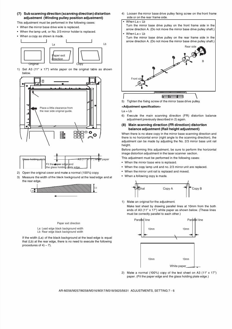
8/9/2019 AR-M318 SM
http://slidepdf.com/reader/full/ar-m318-sm 38/159
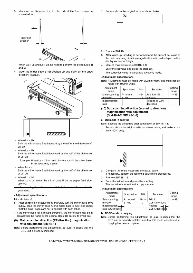
8/9/2019 AR-M318 SM
http://slidepdf.com/reader/full/ar-m318-sm 39/159
AR-M256/M257/M258/M316/M317/M318/5625/5631 ADJUSTMENTS, SETTING 7 - 7
3) Measure the distances (La, Lb, Lc, Ld) at the four corners asshown below.
When La = Lb and Lc = Ld, no need to perform the procedures 4)and 5).
4) Move the mirror base B rail position up and down (in the arrowdirection) to adjust.
<Adjustment specification>La = Lb, Lc = Ld5) After completion of adjustment, manually turn the mirror base drive
pulley, scan the mirror base A and mirror base B fully, and checkthat the mirror bases are not in contact with each other.
If the mirror base rail is moved extremely, the mirror base may be incontact with the frame or the original glass. Be careful to avoid this.
(9) Main scanning direction (FR direction) magnificationratio adjustment (SIM 48-1)
Note: Before performing this adjustment, be sure to check that theCCD unit is properly installed.
1) Put a scale on the original table as shown below.
2) Execute SIM 48-1.3) After warm-up, shading is performed and the current set value of
the main scanning direction magnification ratio is displayed on thedisplay section in 2 digits.
4) Manual correction mode (SIM48-1-1)Enter the set value and press the start key.The correction value is stored and a copy is made.
<Adjustment specification>Note: A judgment must be made with 200mm width, and must not be
made with 100mm width.
(10) Sub scanning direction (scanning direction)magnification ratio adjustment(SIM 48-1-2, SIM 48-1-3)
a. OC mode in copyingNote: Execute the procedure after completion of SIM 48-1-1.1) Put a scale on the original table as shown below, and make a nor-
mal (100%) copy.
2) Compare the scale image and the actual scale.If necessary, perform the following adjustment procedures.
3) Execute SIM 48-1-2.4) Enter the set value and press the start key.
The set value is stored and a copy is made.
<Adjustment specification>
b. RSPF mode in copyingNote: Before performing this adjustment, be sure to check that the
CCD unit is properly installed and that OC mode adjustment incopying has been completed.
• When La > Lb
Shift the mirror base B rail upward by the half of the difference ofLa–Lb.
• When La < LbShift the mirror base B rail downward by the half of the differenceof Lb–La.
Example: When La = 12mm and Lb = 9mm, shift the mirror baseB rail upward by 1.5mm.
• When Lc >Ld
Shift the mirror base B rail downward by the half of the differenceof Lc–Ld.
• When Lc < LdWhen Lc < Ld, move the mirror base B on the paper feed sideupward.When moving the mirror base rail, hold the mirror base rail with
your hand.
La
Lb Ld
Lc
Paper exitdirection
Adjustmentmode
Spec value SIM Set valueSettingrange
Main scanningdirectionmagnificationratio
At normal:±1.0% 48-1-1 Add 1: 0.1%increaseReduce 1: 0.1%decrease
1 – 99
Adjustmentmode
Spec value SIM Set valueSettingrange
Sub scanningdirectionmagnificationratio (OC mode)
At normal:±1.0%
48-1-2
Add 1:0.05% increaseReduce 1:0.05% decrease
1 – 99
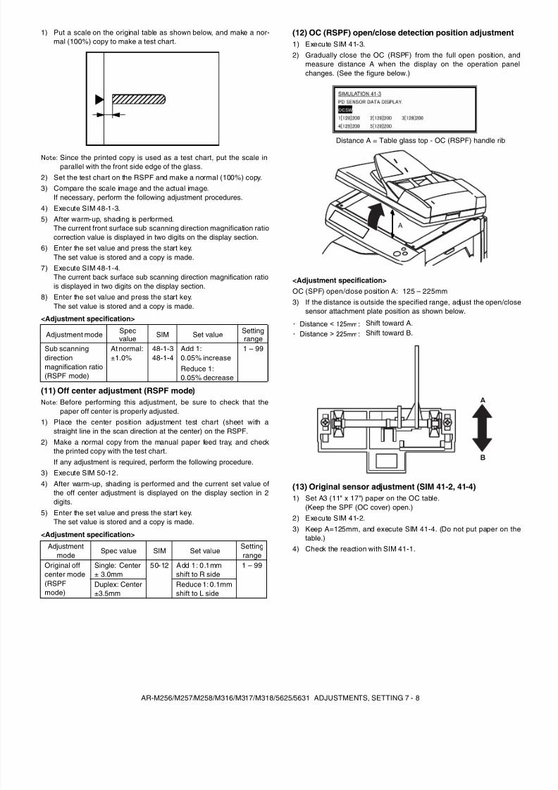
8/9/2019 AR-M318 SM
http://slidepdf.com/reader/full/ar-m318-sm 40/159
AR-M256/M257/M258/M316/M317/M318/5625/5631 ADJUSTMENTS, SETTING 7 - 8
1) Put a scale on the original table as shown below, and make a nor-mal (100%) copy to make a test chart.
Note: Since the printed copy is used as a test chart, put the scale inparallel with the front side edge of the glass.
2) Set the test chart on the RSPF and make a normal (100%) copy.3) Compare the scale image and the actual image.
If necessary, perform the following adjustment procedures.4) Execute SIM 48-1-3.5) After warm-up, shading is performed.
The current front surface sub scanning direction magnification ratiocorrection value is displayed in two digits on the display section.
6) Enter the set value and press the start key.The set value is stored and a copy is made.
7) Execute SIM 48-1-4.
The current back surface sub scanning direction magnification ratiois displayed in two digits on the display section.
8) Enter the set value and press the start key.The set value is stored and a copy is made.
<Adjustment specification>
(11) Off center adjustment (RSPF mode)Note: Before performing this adjustment, be sure to check that the
paper off center is properly adjusted.1) Place the center position adjustment test chart (sheet with a
straight line in the scan direction at the center) on the RSPF.2) Make a normal copy from the manual paper feed tray, and check
the printed copy with the test chart.If any adjustment is required, perform the following procedure.
3) Execute SIM 50-12.4) After warm-up, shading is performed and the current set value of
the off center adjustment is displayed on the display section in 2digits.
5) Enter the set value and press the start key.The set value is stored and a copy is made.
<Adjustment specification>
(12) OC (RSPF) open/close detection position adjustment1) Execute SIM 41-3.2) Gradually close the OC (RSPF) from the full open position, and
measure distance A when the display on the operation panelchanges. (See the figure below.)
Distance A = Table glass top - OC (RSPF) handle rib
<Adjustment specification>OC (SPF) open/close position A: 125 – 225mm3) If the distance is outside the specified range, adjust the open/close
sensor attachment plate position as shown below.
(13) Original sensor adjustment (SIM 41-2, 41-4)1) Set A3 (11" x 17") paper on the OC table.
(Keep the SPF (OC cover) open.)2) Execute SIM 41-2.3) Keep A=125mm, and execute SIM 41-4. (Do not put paper on the
table.)4) Check the reaction with SIM 41-1.
Adjustment mode Specvalue SIM Set value Setting
rangeSub scanningdirectionmagnification ratio(RSPF mode)
At normal:±1.0%
48-1-348-1-4
Add 1:0.05% increaseReduce 1:0.05% decrease
1 – 99
Adjustmentmode Spec value SIM Set value
Settingrange
Original offcenter mode(RSPFmode)
Single: Center± 3.0mm
50-12 Add 1: 0.1mmshift to R side
1 – 99
Duplex: Center±3.5mm
Reduce 1: 0.1mmshift to L side
Distance < 125mm : Shift toward A.Distance > 225mm : Shift toward B.
A
A
B
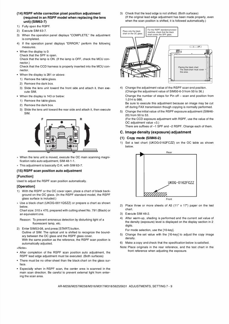
8/9/2019 AR-M318 SM
http://slidepdf.com/reader/full/ar-m318-sm 41/159
AR-M256/M257/M258/M316/M317/M318/5625/5631 ADJUSTMENTS, SETTING 7 - 9
(14) RSPF white correction pixel position adjustment(required in an RSPF model when replacing the lensunit) (SIM63-7)
1) Fully open the RSPF.2) Execute SIM 63-7.3) When the operation panel displays "COMPLETE," the adjustment
is completed.4) If the operation panel displays "ERROR," perform the following
measures.• When the display is 0:
Check that the SPF is open.Check that the lamp is ON. (If the lamp is OFF, check the MCU con-nector.)Check that the CCD harness is properly inserted into the MCU con-nector.
• When the display is 281 or above:1) Remove the table glass.2) Remove the dark box.3) Slide the lens unit toward the front side and attach it, then exe-
cute SIM.• When the display is 143 or below:
1) Remove the table glass.2) Remove the dark box.3) Slide the lens unit toward the rear side and attach it, then execute
SIM.
When the lens unit is moved, execute the OC main scanning magni-fication ratio auto adjustment, SIM 48-1-1.This adjustment is basically O.K. with SIM 63-7.
(15) RSPF scan position auto adjustment[Function]Used to adjust the RSPF scan position automatically.
[Operation]1) With the RSPF or the OC cover open, place a chart of black back-
ground on the OC glass. (In the RSPF standard model, the RSPFglass surface is included.)
Use a black chart (UKOG-0011QSZZ) or prepare a chart as shownbelow.Chart size: 310 x 470, prepared with cutting sheet No. 791 (Black) oran equivalent one.
2) Enter SIM53-08, and press [START] button.Outline of SIM: The optical unit is shifted to recognize the bound-ary between the OC glass and the RSPF glass cover.With the same position as the reference, the RSPF scan position isautomatically adjusted.
<Note>• After completion of the RSPF scan position auto adjustment, the
RSPF lead edge adjustment must be executed. (Both surfaces)• There must be no other sheet than the black chart on the glass sur-
face.• Especially when in RSPF scan, the center area is scanned in the
main scan direction. Be careful to prevent external light from enter-ing the scan area.
3) Check that the lead edge is not shifted. (Both surfaces)(If the original lead edge adjustment has been made properly, evenwhen the scan position is shifted, it is followed automatically.)
4) Change the adjustment value of the RSPF scan end position.(Change the adjustment value of SIM50-6-3 from 50 to 36.)Change the number of steps for Pin off – scan end position from1,014 to 986.Be sure to execute this adjustment because an image may be cutoff during FAX transmission though copying is normally performed.
5) Change the initial value of the RSPF exposure adjustment (SIM46-20) from 50 to 53.(For the CCD exposure adjustment with RSPF, use the value of theOC adjustment value +3.)There are suffixes of –1 SPF and –2 RSPF. Change each of them.
C. Image density (exposure) adjustment(1) Copy mode (SIM46-2)1) Set a test chart (UKOG-0162FCZZ) on the OC table as shown
below.
2) Place three or more sheets of A3 (11" x 17") paper on the testchart.
3) Execute SIM 46-2.4) After warm-up, shading is performed and the current set value of
the density (exposure) level is displayed on the display section in 2
digits.For mode selection, use the [10-key].5) Change the set value with the [10-key] to adjust the copy image
density.6) Make a copy and check that the specification below is satisfied.Note: Place originals in the rear reference, and the test chart in the
front reference when adjusting the exposure.
Reason: To prevent erroneous detection by disturbing light of afluorescent lamp, etc.
RF
Place only the blackchart on the OC glass.
For the RSPF standard-provisionmachine, check that the blackchart covers the SPF glass.
Placing the black chart The black chart must cover this area.
Rear
Front
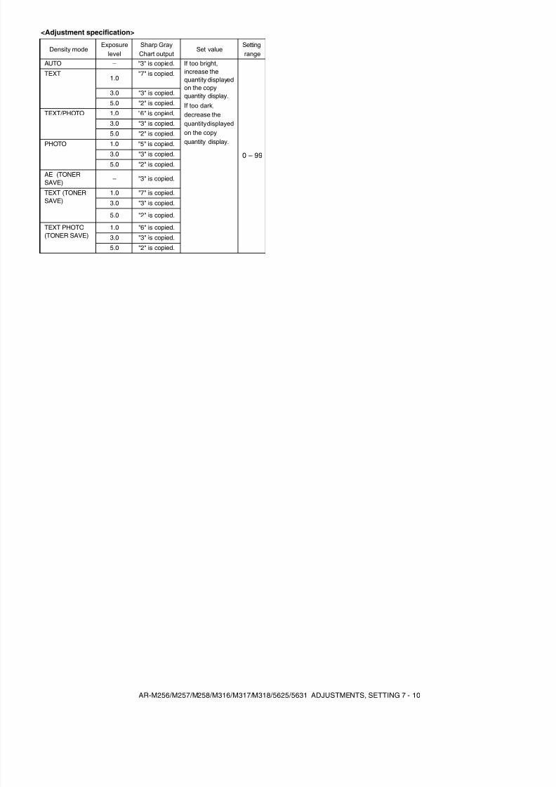
8/9/2019 AR-M318 SM
http://slidepdf.com/reader/full/ar-m318-sm 42/159
AR-M256/M257/M258/M316/M317/M318/5625/5631 ADJUSTMENTS, SETTING 7 - 10
<Adjustment specification>
Density modeExposure
levelSharp GrayChart output
Set valueSettingrange
AUTO – "3" is copied. If too bright,increase thequantity displayedon the copyquantity display.If too dark,decrease thequantity displayedon the copyquantity display.
0 – 99
TEXT1.0
"7" is copied.
3.0 "3" is copied.
5.0 "2" is copied.
TEXT/PHOTO 1.0 "6" is copied.
3.0 "3" is copied.
5.0 "2" is copied.
PHOTO 1.0 "5" is copied.
3.0 "3" is copied.
5.0 "2" is copied.
AE (TONERSAVE)
– "3" is copied.
TEXT (TONERSAVE)
1.0 "7" is copied.
3.0 "3" is copied.
5.0 "2" is copied.
TEXT PHOTO(TONER SAVE)
1.0 "6" is copied.
3.0 "3" is copied.
5.0 "2" is copied.
8/9/2019 AR-M318 SM
http://slidepdf.com/reader/full/ar-m318-sm 43/159
AR-M256/M257/M258/M316/M317/M318/5625/5631 SIMULATION 8 - 1
[8] SIMULATION(Diagnostics, setup, adjustment value input, data display)
1. Outline and purposeThe simulation has the following functions to grasp the machine oper-ating status, identify the trouble position and causes in an earlier stage,and make various setups and adjustments speedily for improving theserviceability of the machine.1) Various adjustments
2) Setup of specifications and functions3) Canceling troubles4) Operation check5) Various counters check, setup, and clear6) Machine operating status (operation history) data check, clear7) Transfer of various data (adjustments, setup, operations, counters)The operating procedures and the displays differ depending on theform of the operation panel of the machine.
2. Code-type simulationA. Operating procedures and operations* Entering the simulation mode1) #/P key (program) ON → Asterisk (*) key ON → CLEAR key ON →
Asterisk (*) key ON → Ready for input of a main code of simulation2) Entering a main code with the 10-key → START key ON
3) Entering a sub code with the 10-key → START key ON4) Select an item with the scroll key and the item key.5) The machine enters the mode corresponding to the selected item.
Press START key to start the simulation operation.To cancel the current simulation mode or to change the main codeand the sub code, press the CUSTOM SETTINGS key.
* Canceling the simulation mode to return to the normal mode1) Press CLEAR ALL key.
B. How to change the simulation adjustment valueset by the touch panel in the adjustment valueentry process
(1) Target SIM list
3-7, 8-1, 8-2, 8-3, 8-10, 8-11, 8-12, 9-5, 43-1, 44-34, 46-2, 46-9, 46-10,46-11, 46-18, 46-20, 46-30, 46-31, 48-1, 48-2, 50-1, 50-5, 50-6, 50-10,50-12, 51-1, 51-2, 51-9, 53-7
(2) Touch panel operating procedure• In the adjustment value setup menu, the selected item is highlighted.
Change is made to the highlighted simulation adjustment value.• If all the list of the adjustment items is not shown on one page, touch
[↑] and [ ↓] button to shift the page.• To change an adjustment value, touch the select the item to change
the adjustment value. (The selected item is highlighted.) Enter theadjustment value and perform one of the following procedures, andthe display of the adjustment value of the selected item is renewedas well as the adjustment value.
1) Touch [OK] button.
2) Touch another selected item to change the selection state.3) If all the list of the adjustment items cover two or more pages,
touch [ ↑] and [ ↓] button to shift the page.4) Press [START] key.* For simulations which allow confirmation print, copying is started
after changing the adjustment value.(46-2, 46-9, 46-10, 46-11, 46-18, 48-1, 48-2, 50-1, 50-5, 50-6, 50-10,50-12, 51-2, the bold-faced items in the above list.)
* If the entry value is outside the adjustable range, an error buzzersounds and the adjustment value is not renewed. Page shift is notmade, either.
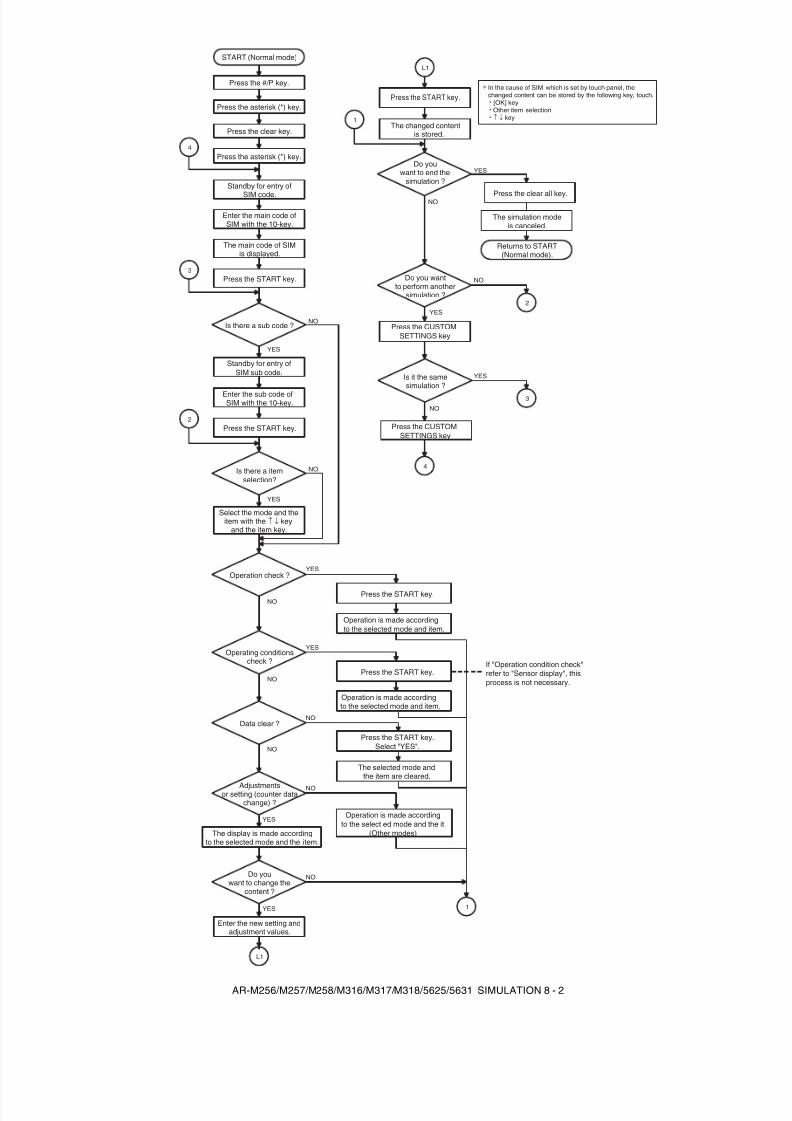
8/9/2019 AR-M318 SM
http://slidepdf.com/reader/full/ar-m318-sm 44/159
AR-M256/M257/M258/M316/M317/M318/5625/5631 SIMULATION 8 - 2
YES
YES
YES
NO
NO
YES
NO
NO
NO
YES
YES
NO
NO
NO
NO
YES
YES
START (Normal mode)
Press the #/P key.
Press the asterisk (*) key.
Press the clear key.
Press the asterisk (*) key.
Standby for entry of
SIM code.
Standby for entry ofSIM sub code.
Enter the main code ofSIM with the 10-key.
Enter the sub code ofSIM with the 10-key.
The main code of SIMis displayed.
Press the START key.
Press the START key.
Is there a sub code ?
Is there a itemselection?
Select the mode and theitem with the ↑ ↓ key
and the item key.
Operation check ?
Operating conditionscheck ?
Data clear ?
Adjustmentsor setting (counter data
change) ?
4
1
L1
3
2
L1
1
4
2
3
NO
Press the START key.
Operation is made accordingto the selected mode and item.
Operation is made accordingto the selected mode and item.
Press the START key.
Press the START key.Select "YES".
The selected mode andthe item are cleared.
The display is made accordingto the selected mode and the item.
Do youwant to change the
content ?
Enter the new setting andadjustment values.
Operation is made accordingto the select ed mode and the it
(Other modes)
Press the START key.
The changed contentis stored.
NO
YES
Press the CUSTOMSETTINGS key
Is it the samesimulation ?
Do youwant to end the
simulation ?
Press the CUSTOMSETTINGS key
Do you wantto perform another
simulation ?
Press the clear all key.
The simulat
Returns to START(Normal mode).
ion modeis canceled.
If "Operation condition check"refer to "Sensor display", thisprocess is not necessary.
In the cause of SIM which is set by touch panel, thechanged content can be stored by the following key, touch.
· [OK] key · Other item selection · ↑ ↓ key
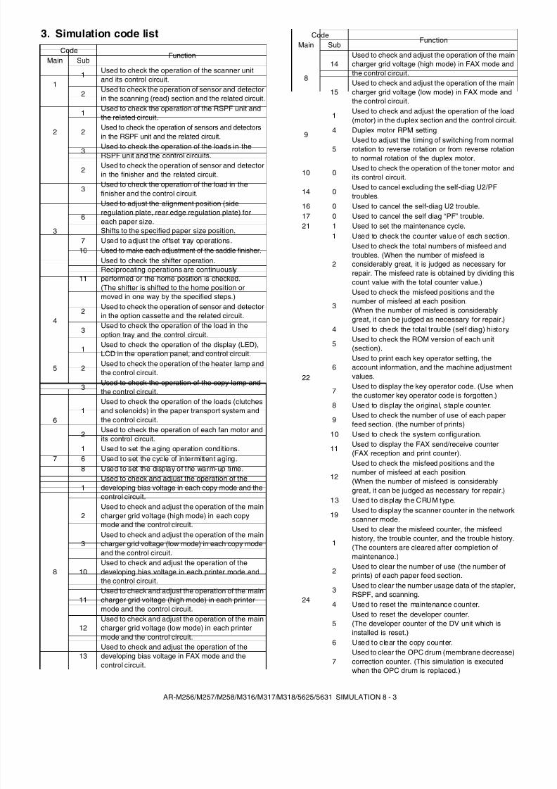
8/9/2019 AR-M318 SM
http://slidepdf.com/reader/full/ar-m318-sm 45/159
AR-M256/M257/M258/M316/M317/M318/5625/5631 SIMULATION 8 - 3
3. Simulation code listCode
FunctionMain Sub
11 Used to check the operation of the scanner unit
and its control circuit.
2 Used to check the operation of sensor and detectorin the scanning (read) section and the related circuit.
2
1 Used to check the operation of the RSPF unit andthe related circuit.
2Used to check the operation of sensors and detectors
in the RSPF unit and the related circuit.3
Used to check the operation of the loads in theRSPF unit and the control circuits.
3
2Used to check the operation of sensor and detectorin the finisher and the related circuit.
3Used to check the operation of the load in thefinisher and the control circuit.
6
Used to adjust the alignment position (sideregulation plate, rear edge regulation plate) foreach paper size.Shifts to the specified paper size position.
7 Used to adjust the offset tray operations.10 Used to make each adjustment of the saddle finisher.
11
Used to check the shifter operation.Reciprocating operations are continuouslyperformed or the home position is checked.(The shifter is shifted to the home position ormoved in one way by the specified steps.)
42
Used to check the operation of sensor and detectorin the option cassette and the related circuit.
3Used to check the operation of the load in theoption tray and the control circuit.
5
1Used to check the operation of the display (LED),LCD in the operation panel, and control circuit.
2Used to check the operation of the heater lamp andthe control circuit.
3Used to check the operation of the copy lamp andthe control circuit.
61
Used to check the operation of the loads (clutchesand solenoids) in the paper transport system andthe control circuit.
2Used to check the operation of each fan motor andits control circuit.
71 Used to set the aging operation conditions.6 Used to set the cycle of intermittent aging.8 Used to set the display of the warm-up time.
8
1Used to check and adjust the operation of thedeveloping bias voltage in each copy mode and thecontrol circuit.
2Used to check and adjust the operation of the maincharger grid voltage (high mode) in each copymode and the control circuit.
3Used to check and adjust the operation of the maincharger grid voltage (low mode) in each copy mode
and the control circuit.
10Used to check and adjust the operation of thedeveloping bias voltage in each printer mode andthe control circuit.
11Used to check and adjust the operation of the maincharger grid voltage (high mode) in each printermode and the control circuit.
12Used to check and adjust the operation of the maincharger grid voltage (low mode) in each printermode and the control circuit.
13Used to check and adjust the operation of thedeveloping bias voltage in FAX mode and thecontrol circuit.
8
14Used to check and adjust the operation of the maincharger grid voltage (high mode) in FAX mode andthe control circuit.
15Used to check and adjust the operation of the maincharger grid voltage (low mode) in FAX mode andthe control circuit.
9
1 Used to check and adjust the operation of the load(motor) in the duplex section and the control circuit.
4 Duplex motor RPM setting
5Used to adjust the timing of switching from normalrotation to reverse rotation or from reverse rotationto normal rotation of the duplex motor.
10 0Used to check the operation of the toner motor andits control circuit.
14 0Used to cancel excluding the self-diag U2/PFtroubles.
16 0 Used to cancel the self-diag U2 trouble.17 0 Used to cancel the self diag “PF” trouble.21 1 Used to set the maintenance cycle.
22
1 Used to check the counter value of each section.
2
Used to check the total numbers of misfeed andtroubles. (When the number of misfeed isconsiderably great, it is judged as necessary for
repair. The misfeed rate is obtained by dividing thiscount value with the total counter value.)
3
Used to check the misfeed positions and thenumber of misfeed at each position.(When the number of misfeed is considerablygreat, it can be judged as necessary for repair.)
4 Used to check the total trouble (self diag) history.
5Used to check the ROM version of each unit(section).
6Used to print each key operator setting, theaccount information, and the machine adjustmentvalues.
7Used to display the key operator code. (Use whenthe customer key operator code is forgotten.)
8 Used to display the original, staple counter.
9 Used to check the number of use of each paperfeed section. (the number of prints)
10 Used to check the system configuration.
11 Used to display the FAX send/receive counter(FAX reception and print counter).
12
Used to check the misfeed positions and thenumber of misfeed at each position.(When the number of misfeed is considerablygreat, it can be judged as necessary for repair.)
13 Used to display the CRUM type.
19Used to display the scanner counter in the networkscanner mode.
24
1
Used to clear the misfeed counter, the misfeedhistory, the trouble counter, and the trouble history.(The counters are cleared after completion ofmaintenance.)
2 Used to clear the number of use (the number ofprints) of each paper feed section.
3 Used to clear the number usage data of the stapler,RSPF, and scanning.
4 Used to reset the maintenance counter.
5Used to reset the developer counter.(The developer counter of the DV unit which isinstalled is reset.)
6 Used to clear the copy counter.
7Used to clear the OPC drum (membrane decrease)correction counter. (This simulation is executedwhen the OPC drum is replaced.)
CodeFunction
Main Sub
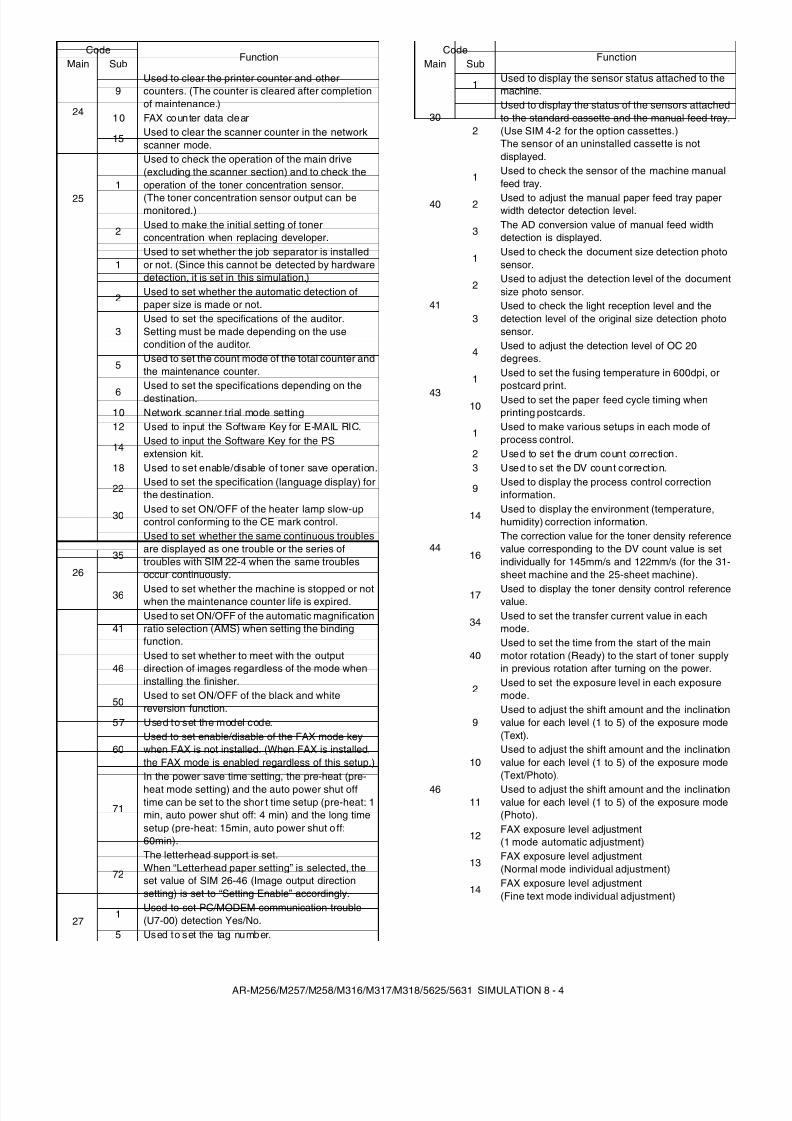
8/9/2019 AR-M318 SM
http://slidepdf.com/reader/full/ar-m318-sm 46/159
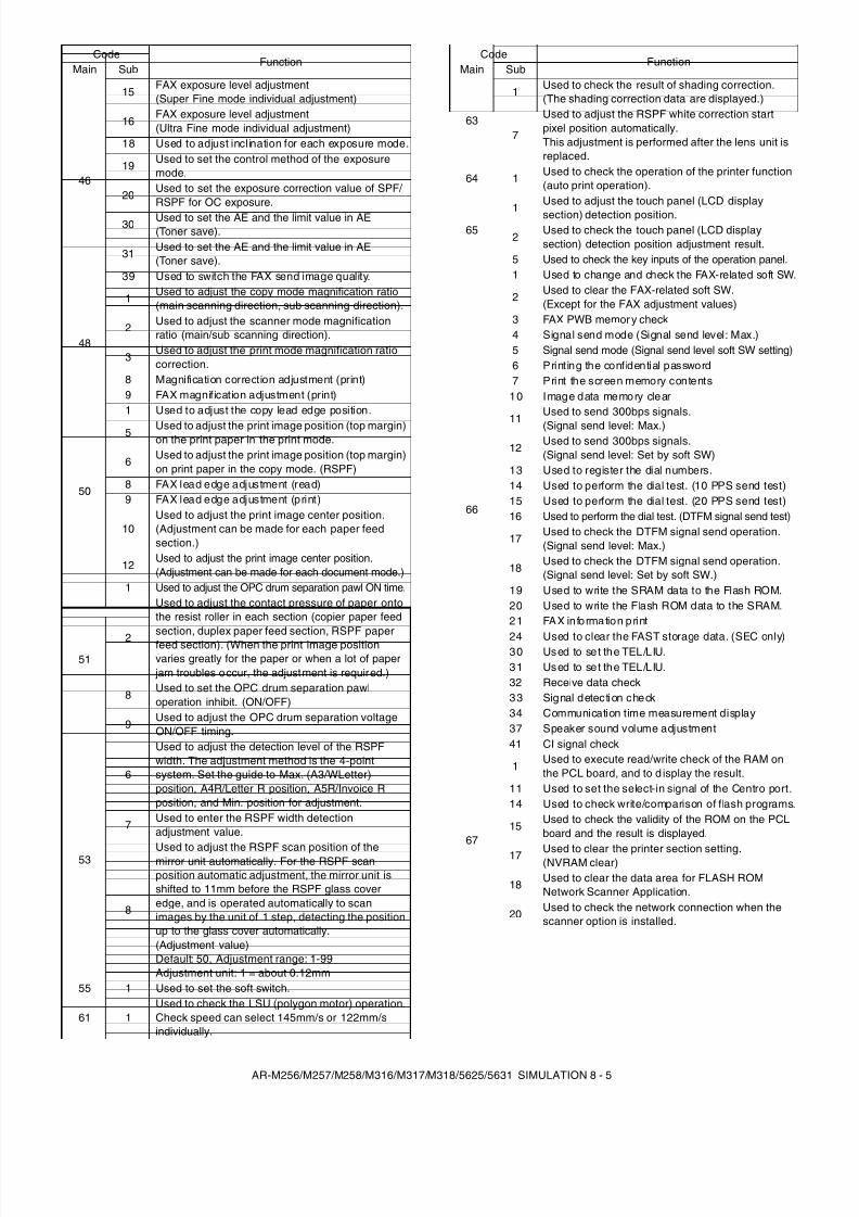
8/9/2019 AR-M318 SM
http://slidepdf.com/reader/full/ar-m318-sm 47/159
AR-M256/M257/M258/M316/M317/M318/5625/5631 SIMULATION 8 - 5
46
15FAX exposure level adjustment(Super Fine mode individual adjustment)
16FAX exposure level adjustment(Ultra Fine mode individual adjustment)
18 Used to adjust inclination for each exposure mode.
19 Used to set the control method of the exposuremode.
20Used to set the exposure correction value of SPF/ RSPF for OC exposure.
30 Used to set the AE and the limit value in AE(Toner save).
31 Used to set the AE and the limit value in AE(Toner save).
39 Used to switch the FAX send image quality.
48
1 Used to adjust the copy mode magnification ratio(main scanning direction, sub scanning direction).
2 Used to adjust the scanner mode magnificationratio (main/sub scanning direction).
3Used to adjust the print mode magnification ratiocorrection.
8 Magnification correction adjustment (print)9 FAX magnification adjustment (print)
50
1 Used to adjust the copy lead edge position.
5 Used to adjust the print image position (top margin)on the print paper in the print mode.
6 Used to adjust the print image position (top margin)on print paper in the copy mode. (RSPF)
8 FAX lead edge adjustment (read)9 FAX lead edge adjustment (print)
10Used to adjust the print image center position.(Adjustment can be made for each paper feedsection.)
12Used to adjust the print image center position.(Adjustment can be made for each document mode.)
51
1 Used to adjust the OPC drum separation pawl ON time.
2
Used to adjust the contact pressure of paper ontothe resist roller in each section (copier paper feedsection, duplex paper feed section, RSPF paperfeed section). (When the print image positionvaries greatly for the paper or when a lot of paper
jam troubles occur, the adjustment is required.)
8Used to set the OPC drum separation pawloperation inhibit. (ON/OFF)
9Used to adjust the OPC drum separation voltageON/OFF timing.
53
6
Used to adjust the detection level of the RSPFwidth. The adjustment method is the 4-pointsystem. Set the guide to Max. (A3/WLetter)position, A4R/Letter R position, A5R/Invoice Rposition, and Min. position for adjustment.
7Used to enter the RSPF width detectionadjustment value.
8
Used to adjust the RSPF scan position of themirror unit automatically. For the RSPF scanposition automatic adjustment, the mirror unit isshifted to 11mm before the RSPF glass coveredge, and is operated automatically to scanimages by the unit of 1 step, detecting the positionup to the glass cover automatically.(Adjustment value)Default: 50, Adjustment range: 1-99Adjustment unit: 1 = about 0.12mm
55 1 Used to set the soft switch.
61 1Used to check the LSU (polygon motor) operation.Check speed can select 145mm/s or 122mm/sindividually.
CodeFunction
Main Sub
63
1Used to check the result of shading correction.(The shading correction data are displayed.)
7
Used to adjust the RSPF white correction startpixel position automatically.This adjustment is performed after the lens unit isreplaced.
64 1 Used to check the operation of the printer function(auto print operation).
651
Used to adjust the touch panel (LCD displaysection) detection position.
2Used to check the touch panel (LCD displaysection) detection position adjustment result.
5 Used to check the key inputs of the operation panel.
66
1 Used to change and check the FAX-related soft SW.
2Used to clear the FAX-related soft SW.(Except for the FAX adjustment values)
3 FAX PWB memor y check4 Signal send mode (Signal send level: Max.)5 Signal send mode (Signal send level soft SW setting)6 Printing the confidential password7 Print the screen memory contents
10 Image data memory clear
11Used to send 300bps signals.
(Signal send level: Max.)12
Used to send 300bps signals.(Signal send level: Set by soft SW)
13 Used to register the dial numbers.14 Used to perform the dial test. (10 PPS send test)15 Used to perform the dial test. (20 PPS send test)16 Used to perform the dial test. (DTFM signal send test)
17Used to check the DTFM signal send operation.(Signal send level: Max.)
18Used to check the DTFM signal send operation.(Signal send level: Set by soft SW.)
19 Used to write the SRAM data to the Flash ROM.20 Used to write the Flash ROM data to the SRAM.21 FAX information print
24 Used to clear the FAST storage data. (SEC only)30 Used to set the TEL/LIU.31 Used to set the TEL/LIU.32 Receive data check33 Signal detection check34 Communication time measurement display37 Speaker sound volume adjustment41 CI signal check
67
1Used to execute read/write check of the RAM onthe PCL board, and to d isplay the result.
11 Used to set the select-in signal of the Centro port.14 Used to check write/comparison of flash programs.
15Used to check the validity of the ROM on the PCLboard and the result is displayed.
17 Used to clear the printer section setting.(NVRAM clear)
18 Used to clear the data area for FLASH ROMNetwork Scanner Application.
20 Used to check the network connection when thescanner option is installed.
CodeFunction
Main Sub
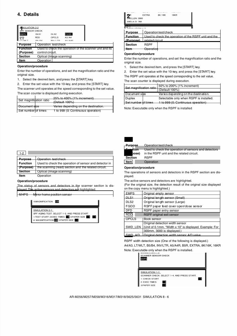
8/9/2019 AR-M318 SM
http://slidepdf.com/reader/full/ar-m318-sm 48/159
AR-M256/M257/M258/M316/M317/M318/5625/5631 SIMULATION 8 - 6
4. Details
Operation/procedureEnter the number of operations, and set the magnification ratio and theoriginal size.1. Select the desired item, and press the [START] key.2. Enter the set value with the 10-key, and press the [START] key.The scanner unit operates at the speed corresponding to the set value.The scan counter is displayed during execution.
Operation/procedureThe status of sensors and detectors in the scanner section is dis-played. The active sensors and detectors are highlighted.
Operation/procedure
Enter the number of operations, and set the magnification ratio and theoriginal size.1. Select the desired item, and press the [START] key.2. Enter the set value with the 10-key, and press the [START] key.The RSPF unit operates at the speed corresponding to the set value.The scan counter is displayed during execution.
Note: Executable only when the RSPF is installed.
Operation/procedureThe operations of sensors and detectors in the RSPF section are dis-
played.The active sensors and detectors are highlighted.(For the original size, the detection result of the original size displayedon the copy menu is highlighted.)
RSPF width detection size (One of the following is displayed.)A4/A3, LT/WLT, B5/B4, INV/LTR, A5/A4R, B5R, EXTRA, 8K/16K, 16KRNote: Executable only when the RSPF is installed.
1
1-1
Purpose Operation test/checkFunction(Purpose)
Used to check the operation of the scanner unit and itscontrol circuit.
Section Optical (Image scanning)Item Operation
Set magnification ratio25% to 400% (1% increment)(Default 100%)
Document size Varies depending on the destination.Set number of times 1 to 999 (0: Continuous operation)
1-2
Purpose Operation test/checkFunction(Purpose)
Used to check the operation of sensor and detector inthe scanning (read) section and the related circuit.
Section Optical (Image scanning)
Item Operation
MHPS Mirror home position sensor
2
2-1
Purpose Operation test/checkFunction(Purpose)
Used to check the operation of the RSPF unit and therelated circuit.
Section RSPFItem Operation
Set magnification ratio50% to 200% (1% increment)(Default 100%)
Document size Var ies depending on the destinat ion.Duplex Selectable only when RSPF is installed.Set number of times 1 to 999 (0: Continuous operation)
2-2
Purpose Operation test/checkFunction(Purpose)
Used to check the operation of sensors and detectorsin the RSPF unit and the related circuit.
Section RSPFItem Operation
EMPS Original empty sensorDLS1 Or iginal len gth sensor (Small)DLS2 Or iginal len gth sensor (Large)FGOD RSPF paper feed cover open/close sensorDFD RSPF paper entry sensorRDD RSPF original exit sensorOPCLS Book sensor
SWD_LENOriginal detection width sensor(Unit of 0.1mm. “Width x 10” is displayed. Example: For300mm, 3000 is displayed.)
SWD_A/D Original detection width sensor A/D value
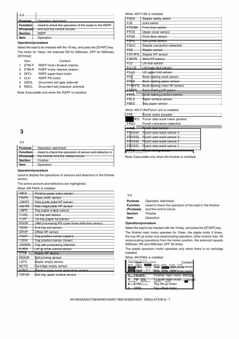
8/9/2019 AR-M318 SM
http://slidepdf.com/reader/full/ar-m318-sm 49/159
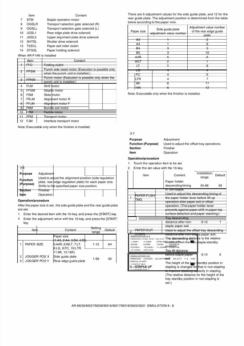
8/9/2019 AR-M318 SM
http://slidepdf.com/reader/full/ar-m318-sm 50/159
AR-M256/M257/M258/M316/M317/M318/5625/5631 SIMULATION 8 - 8
When AR-F14N is installed
Note: Executable only when the finisher is installed.
Operation/procedureAfter the paper size is set, the side guide plate and the rear guide plateare set.1. Enter the desired item with the 10-key, and press the [START] key.2. Enter the adjustment value with the 10-key, and press the [START]
key.
There are 6 adjustment values for the side guide plate, and 12 for therear guide plate. The adjustment position is determined from the tablebelow according to the paper size.
Note: Executable only when the finisher is installed.
Operation/procedure1. Touch the operation item to be set.2. Enter the set value with the 10-key.
7 STM Staple operation motor8 OGSLR Transpor t selection gate solenoid (R)9 OGSLL Transpor t selection gate solenoid (L)
10 JGSL1 Rear edge plate drive solenoid11 JGSL2 Upper alignment plate drive solenoid12 SHTSL Shutter drive solenoid13 T2SCL Paper exit roller clutch14 STGSL Paper holding solenoid
Item Content1 FFC Folding clutch
2 FPSMPunch side resist motor (Execution is possible onlywhen the punch unit is installed.)
3 FPNMPunch motor (Execution is possible only when thepunch unit is installed.)
4 FLM Shift motor5 FFSM Stapler motor6 FSM Slide motor7 FRJM Alignment motor R8 FFJM Alignment motor F9 FAM Bundle exit motor
10 FPM Paddle motor11 FFM Transport motor
12 FJM Interface transport motor
3-6
Purpose Adjustment
Function(Purpose)
Used to adjust the alignment position (side regulation
plate, rear edge regulation plate) for each paper size.Shifts to the specified paper size position.
Section FinisherItem Operation
Item ContentSettingrange Default
1 PAPER SIZE
Paper size(1:A3, 2:A4, 3:B4, 4:B5,5:A4R, 6:WLT, 7:LT,8:LG, 9:FC, 10:LTR,11:8K, 12:16K)
1-12 A4
2 JOGGER POS X Side guide plate1-99 50
3 JOGGER POS Y Rear edge guide p late
Item Content
Paper sizeSide guide plate
adjustment value number
Adjustment value numberof the rear edge guide
plateA3 1 2A4 1 9B4 3 3B5 3 10
A4R 5 6WLT 2 1LT 2 8LG 4 4FC 4 5LTR 4 78K 6 11
16K 6 12
3-7
Purpose AdjustmentFunction (Purpose) Used to adjust the offset tray operations.Section FinisherItem Operation
Item ContentInstallation
rangeDefault
1PAPER PUSHTMG
Paper holderdescending timingin non-staple
34-66 50
Used to adjust the descending timing ofthe paper holder lever before lift-upoperation after paper exit or offsetoperation. (The paper holder leverprevents against paper shift in paper topsurface detection and paper stacking.)
2PAPER OUTDOWN
Tray descendingdistance after non-staple paper exit
0-12 1
Used to adjust the offset tray descendingdistance after non-staple paper exit.The descending distance is the relative
distance from the non-staple standbyposition.
3 STAPLE UP
Tray lift distancebefore staple paperexit
0-12 6
The height of the tray standby position instapling is changed for that in non-staplingto improve stacking capacity in stapling.(The relative distance for the height of thetray standby position in non-stapling isset.)
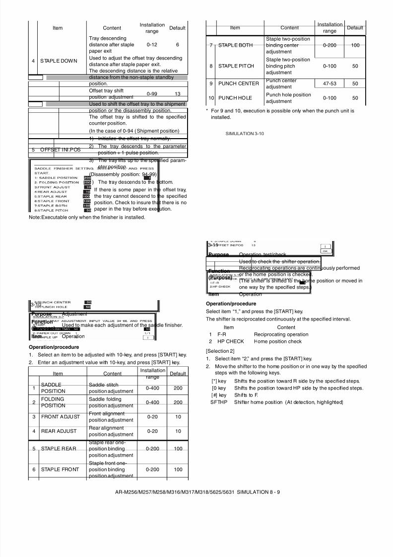
8/9/2019 AR-M318 SM
http://slidepdf.com/reader/full/ar-m318-sm 51/159
AR-M256/M257/M258/M316/M317/M318/5625/5631 SIMULATION 8 - 9
Note:Executable only when the finisher is installed.
Operation/procedure1. Select an item to be adjusted with 10-key, and press [START] key.2. Enter an adjustment value with 10-key, and press [START] key.
* For 9 and 10, execution is possible only when the punch unit isinstalled.
Operation/procedureSelect item “1,” and press the [START] key.The shifter is reciprocated continuously at the specified interval.
[Selection 2]1. Select item “2,” and press the [START] key.2. Move the shifter to the home position or in one way by the specified
steps with the following keys.
4 STAPLE DOWN
Tray descendingdistance after staplepaper exit
0-12 6
Used to adjust the offset tray descendingdistance after staple paper exit.The descending distance is the relativedistance from the non-staple standbyposition.
5 OFFSET INI.POS
Offset tray shift
position adjustment0-99 13
Used to shift the offset tray to the shipmentposition or the disassembly position.The offset tray is shifted to the specifiedcounter position.(In the case of 0-94 (Shipment position)1) Initialize the offset tray normally.2) The tray descends to the parameter
position + 1 pulse position.3) The tray lifts up to the specified param-
eter position.(Disassembly position: 94-99)1) The tray descends to the bottom.* If there is some paper in the offset tray,
the tray cannot descend to the specifiedposition. Check to insure that there is nopaper in the tray before execution.
3-10
Purpose Adjustment
Function(Purpose)
Used to make each adjustment of the saddle finisher.
Item Operation
Item ContentInstallation
rangeDefault
1SADDLEPOSITION
Saddle stitchposition adjustment 0-400 200
2FOLDINGPOSITION
Saddle foldingposition adjustment
0-400 200
3 FRONT ADJUSTFront alignmentposition adjustment
0-20 10
4 REAR ADJUSTRear alignmentposition adjustment
0-20 10
5 STAPLE REARStaple rear one-position bindingposition adjustment
0-200 100
6 STAPLE FRONTStaple front one-position bindingposition adjustment
0-200 100
Item Content Installationrange
Default
7 STAPLE BOTHStaple two-positionbinding centeradjustment
0-200 100
8 STAPLE PITCHStaple two-positionbinding pitchadjustment
0-100 50
9 PUNCH CENTER Punch centeradjustment
47-53 50
10 PUNCH HOLEPunch hole positionadjustment 0-100 50
3-11
Purpose Operation test/check
Function(Purpose)
Used to check the shifter operation.Reciprocating operations are continuously performedor the home position is checked.(The shifter is shifted to the home position or moved inone way by the specified steps.)
Item Operation
Item Content1 F-R Reciprocating operation2 HP CHECK Home position check
[*] key Shifts the position toward R side by the specified steps.
[0 key Shifts the position toward HP side by the specified steps.[#] key Shif ts to F.SFTHP Shifter home position (At detection, highlighted)
Item ContentInstallation
rangeDefault
SIMULATION 3-10
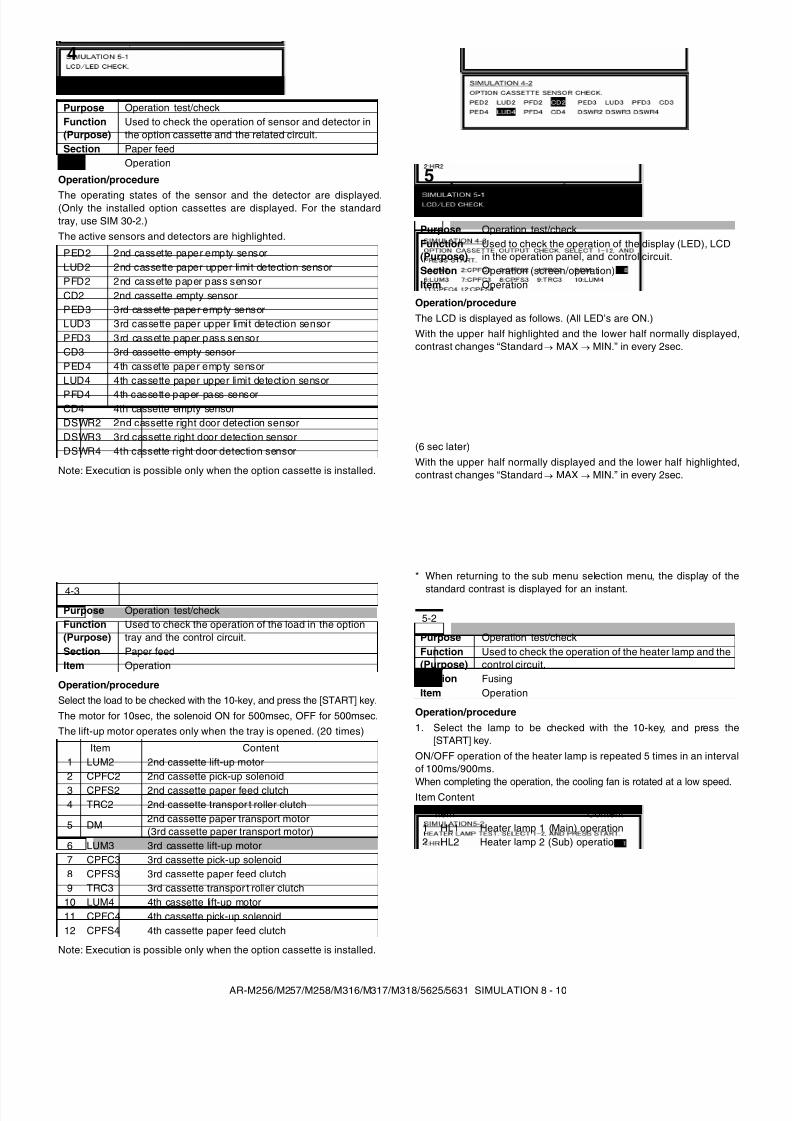
8/9/2019 AR-M318 SM
http://slidepdf.com/reader/full/ar-m318-sm 52/159
AR-M256/M257/M258/M316/M317/M318/5625/5631 SIMULATION 8 - 10
Operation/procedure
The operating states of the sensor and the detector are displayed.(Only the installed option cassettes are displayed. For the standardtray, use SIM 30-2.)The active sensors and detectors are highlighted.
Note: Execution is possible only when the option cassette is installed.
Operation/procedureSelect the load to be checked with the 10-key, and press the [START] key.The motor for 10sec, the solenoid ON for 500msec, OFF for 500msec.The lift-up motor operates only when the tray is opened. (20 times)
Note: Execution is possible only when the option cassette is installed.
Operation/procedureThe LCD is displayed as follows. (All LED’s are ON.)With the upper half highlighted and the lower half normally displayed,contrast changes “Standard → MAX → MIN.” in every 2sec.
(6 sec later)With the upper half normally displayed and the lower half highlighted,contrast changes “Standard → MAX → MIN.” in every 2sec.
* When returning to the sub menu selection menu, the display of the
standard contrast is displayed for an instant.
Operation/procedure1. Select the lamp to be checked with the 10-key, and press the
[START] key.ON/OFF operation of the heater lamp is repeated 5 times in an intervalof 100ms/900ms.
When completing the operation, the cooling fan is rotated at a low speed.Item Content
4
4-2
Purpose Operation test/checkFunction(Purpose)
Used to check the operation of sensor and detector inthe option cassette and the related circuit.
Section Paper feedItem Operation
PED2 2nd cassette paper empty sensorLUD2 2nd cassette paper upper limit detection sensorPFD2 2nd cassette paper pass sensorCD2 2nd cassette empty sensorPED3 3rd cassette paper empty sensorLUD3 3rd cassette paper upper limit detection sensorPFD3 3rd cassette paper pass sensorCD3 3rd cassette empty sensorPED4 4th cassette paper empty sensorLUD4 4th cassette paper upper limit detection sensor
PFD4 4th cassette paper pass sensorCD4 4th cassette empty sensorDSWR2 2nd cassette right door detection sensorDSWR3 3rd cassette right door detection sensorDSWR4 4th cassette right door detection sensor
4-3
Purpose Operation test/checkFunction(Purpose)
Used to check the operation of the load in the optiontray and the control circuit.
Section Paper feedItem Operation
Item Content1 LUM2 2nd cassette lift-up motor2 CPFC2 2nd cassette pick-up solenoid3 CPFS2 2nd cassette paper feed clutch4 TRC2 2nd cassette transpor t roller clutch
5 DM2nd cassette paper transport motor(3rd cassette paper transport motor)
6 LUM3 3rd cassette lift-up motor7 CPFC3 3rd cassette pick-up solenoid8 CPFS3 3rd cassette paper feed clutch9 TRC3 3rd cassette transpor t roller clutch
10 LUM4 4th cassette lift-up motor11 CPFC4 4th cassette pick-up solenoid12 CPFS4 4th cassette paper feed clutch
5
5-1
Purpose Operation test/checkFunction(Purpose)
Used to check the operation of the display (LED), LCDin the operation panel, and control circuit.
Section Operation (screen/operation)Item Operation
5-2
Purpose Operation test/checkFunction(Purpose)
Used to check the operation of the heater lamp and thecontrol circuit.
Section FusingItem Operation
Item Content1 HL1 Heater lamp 1 (Main) operation2 HL2 Heater lamp 2 (Sub) operation
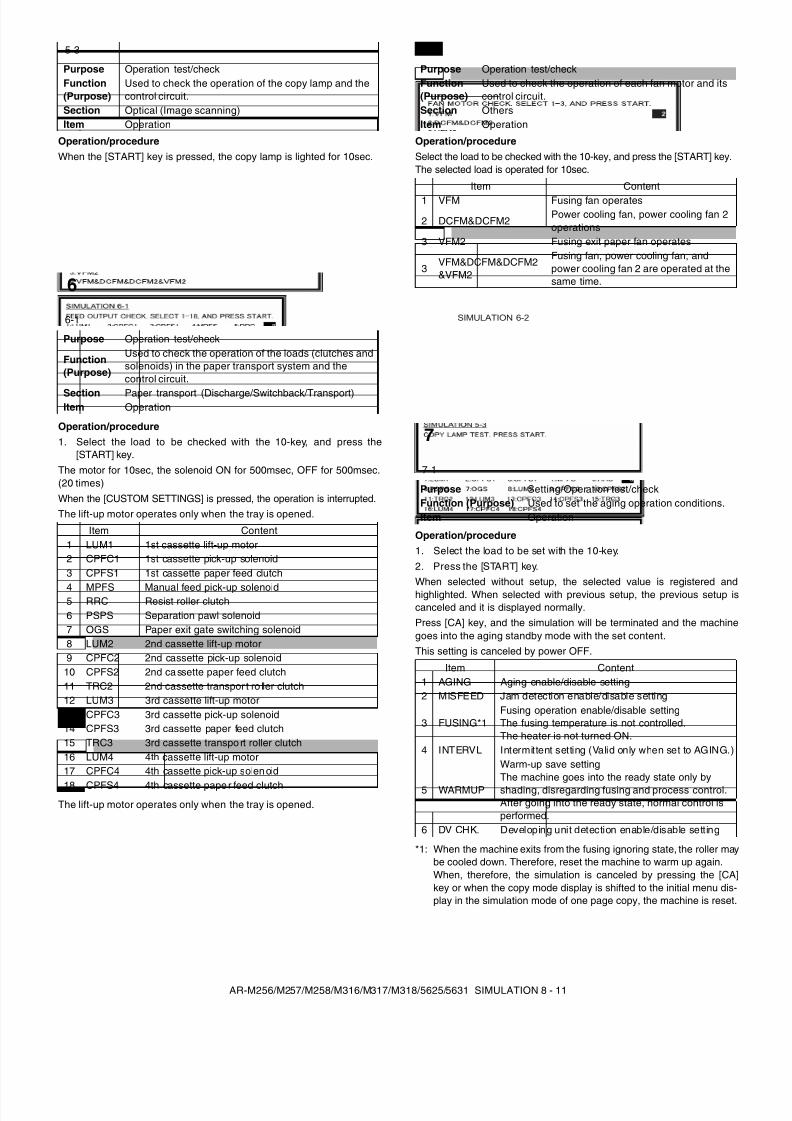
8/9/2019 AR-M318 SM
http://slidepdf.com/reader/full/ar-m318-sm 53/159
AR-M256/M257/M258/M316/M317/M318/5625/5631 SIMULATION 8 - 11
Operation/procedureWhen the [START] key is pressed, the copy lamp is lighted for 10sec.
Operation/procedure1. Select the load to be checked with the 10-key, and press the
[START] key.The motor for 10sec, the solenoid ON for 500msec, OFF for 500msec.(20 times)When the [CUSTOM SETTINGS] is pressed, the operation is interrupted.The lift-up motor operates only when the tray is opened.
The lift-up motor operates only when the tray is opened.
Operation/procedureSelect the load to be checked with the 10-key, and press the [START] key.The selected load is operated for 10sec.
Operation/procedure1. Select the load to be set with the 10-key.2. Press the [START] key.When selected without setup, the selected value is registered andhighlighted. When selected with previous setup, the previous setup iscanceled and it is displayed normally.Press [CA] key, and the simulation will be terminated and the machinegoes into the aging standby mode with the set content.This setting is canceled by power OFF.
*1: When the machine exits from the fusing ignoring state, the roller maybe cooled down. Therefore, reset the machine to warm up again.When, therefore, the simulation is canceled by pressing the [CA]key or when the copy mode display is shifted to the initial menu dis-play in the simulation mode of one page copy, the machine is reset.
5-3
Purpose Operation test/checkFunction(Purpose)
Used to check the operation of the copy lamp and thecontrol circuit.
Section Optical (Image scanning)Item Operation
6
6-1
Purpose Operation test/check
Function(Purpose)
Used to check the operation of the loads (clutches andsolenoids) in the paper transport system and thecontrol circuit.
Section Paper transport (Discharge/Switchback/Transport)Item Operation
Item Content1 LUM1 1st cassette lift-up motor2 CPFC1 1st cassette pick-up solenoid3 CPFS1 1st cassette paper feed clutch
4 MPFS Manual feed pick-up solenoid5 RRC Resist roller clutch6 PSPS Separation pawl solenoid7 OGS Paper exit gate switching solenoid8 LUM2 2nd cassette lift-up motor9 CPFC2 2nd cassette pick-up solenoid
10 CPFS2 2nd cassette paper feed clutch11 TRC2 2nd cassette transpor t ro ller clutch12 LUM3 3rd cassette lift-up motor13 CPFC3 3rd cassette pick-up solenoid14 CPFS3 3rd cassette paper feed clutch15 TRC3 3rd cassette transpo rt roller clutch16 LUM4 4th cassette lift-up motor17 CPFC4 4th cassette pick-up solen oid
18 CPFS4 4th cassette paper feed clutch
6-2
Purpose Operation test/checkFunction(Purpose)
Used to check the operation of each fan motor and itscontrol circuit.
Section OthersItem Operation
Item Content1 VFM Fusing fan operates
2 DCFM&DCFM2Power cooling fan, power cooling fan 2operations
3 VFM2 Fusing exit paper fan operates
3VFM&DCFM&DCFM2&VFM2
Fusing fan, power cooling fan, andpower cooling fan 2 are operated at thesame time.
7
7-1
Purpose Setting/Operation test/checkFunction (Purpose) Used to set the aging operation conditions.Item Operation
Item Content1 AGING Aging enable/disable setting2 MISFEED Jam detection enable/disable setting
3 FUSING*1Fusing operation enable/disable settingThe fusing temperature is not controlled.The heater is not turned ON.
4 INTERVL Intermittent setting (Valid only when set to AGING.)
5 WARMUP
Warm-up save settingThe machine goes into the ready state only byshading, disregarding fusing and process control.After going into the ready state, normal control isperformed.
6 DV CHK. Developing unit detection enable/disable setting
SIMULATION 6-2
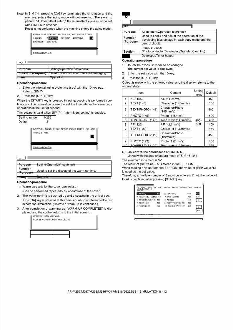
8/9/2019 AR-M318 SM
http://slidepdf.com/reader/full/ar-m318-sm 54/159
AR-M256/M257/M258/M316/M317/M318/5625/5631 SIMULATION 8 - 12
Note: In SIM 7-1, pressing [CA] key terminates the simulation and themachine enters the aging mode without resetting. Therefore, toperform “4. Intermittent setup,” the intermittent cycle must be setwith SIM 7-6 in advance.Reset is not performed when the machine enters the aging mode.
Operation/procedure1. Enter the interval aging cycle time (sec) with the 10-key pad.
Refer to SIM 7-1.2. Press the [START] key.When the [START] key is pressed in aging, copying is performed con-tinuously. This simulation is used to set the time interval between copyoperations in the unit of second.This setting is valid when SIM 7-1 (Intermittent setting) is enabled.
Operation/procedure1. Warm-up starts by the cover open/close.
(Can be performed repeatedly by open/close of the cover.)2. The warm-up time is counted up and displayed in the unit of sec.
If the [CA] key is pressed at this time, count-up is interrupted to ter-minate the simulation. (However, warm-up is continued.)
3. After completion of warming up, “WARM UP COMPLETED” is dis-played and the control returns to the initial screen.
Operation/procedure1. Touch the exposure mode to be changed.
The current set value is displayed.2. Enter the set value with the 10-key.3. Press the [START] key.Output is made with the entered value, and the display returns to theoriginal state.
( ) Linked with the destinations of SIM 26-6.Linked with the auto exposure mode of SIM 46-19-1.
The minimum increment is 5V.The result of (Set value) / 5 is stored in the EEPROM.When reading a value from the EEPROM, the value of (EEP value *5)is used as the set value.Therefore, a multiple number of 5 must be entered. If not, the value +1to +4 is displayed after pressing [START] key.
7-6
Purpose Setting/Operation test/checkFunction (Purpose) Used to set the cycle of intermittent aging.Item Operation
Setting range 1-255Default 3
7-8
Purpose Setting/Operation test/checkFunction
(Purpose)Used to set the display of the warm-up time.
Item Operation
8
8-1
Purpose Adjustment/Operation test/check
Function(Purpose)
Used to check and adjust the operation of thedeveloping bias voltage in each copy mode and thecontrol circuit.
SectionImage process(Photoconductor/Developing/Transfer/Cleaning)Developer/Toner hopper
Item ContentSettingrange Default
1 AE (145) AE (145mm/s)
200-650
4502 TEXT (145) Character (145mm/s) 500
3 TEXT/PHOTO (145) Character/Photo(145mm/s)
500
4 PHOTO (145) Photo (145mm/s) 5005 TONER SAVE (145) Toner save (145mm/s) 4006 AE (122) AE (122mm/s) 4007 TEXT (122) Character (122mm/s) 450
8 TEXT/PHOTO (122)Character/Photo(122mm/s)
450
9 PHOTO (122) Photo (122mm/s) 45010 TONER SAVE (122) Toner save (122mm/s) 376
SIMULATION 8-1
4261/1
DV BIAS COPY SETTING. INPUT VALUE 200-550, AND PRESSSTART.1: AE 4262: TEXT 4503: TEXT/PHOTO 4504: PHOTO 4505: SUPER/PHOTO 4006: TONER SAVE 376
SIMULATION 8-1
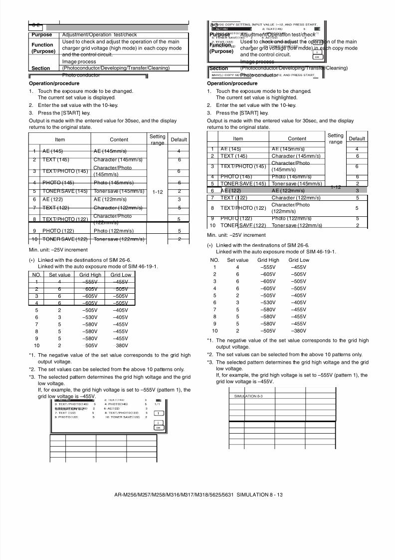
8/9/2019 AR-M318 SM
http://slidepdf.com/reader/full/ar-m318-sm 55/159
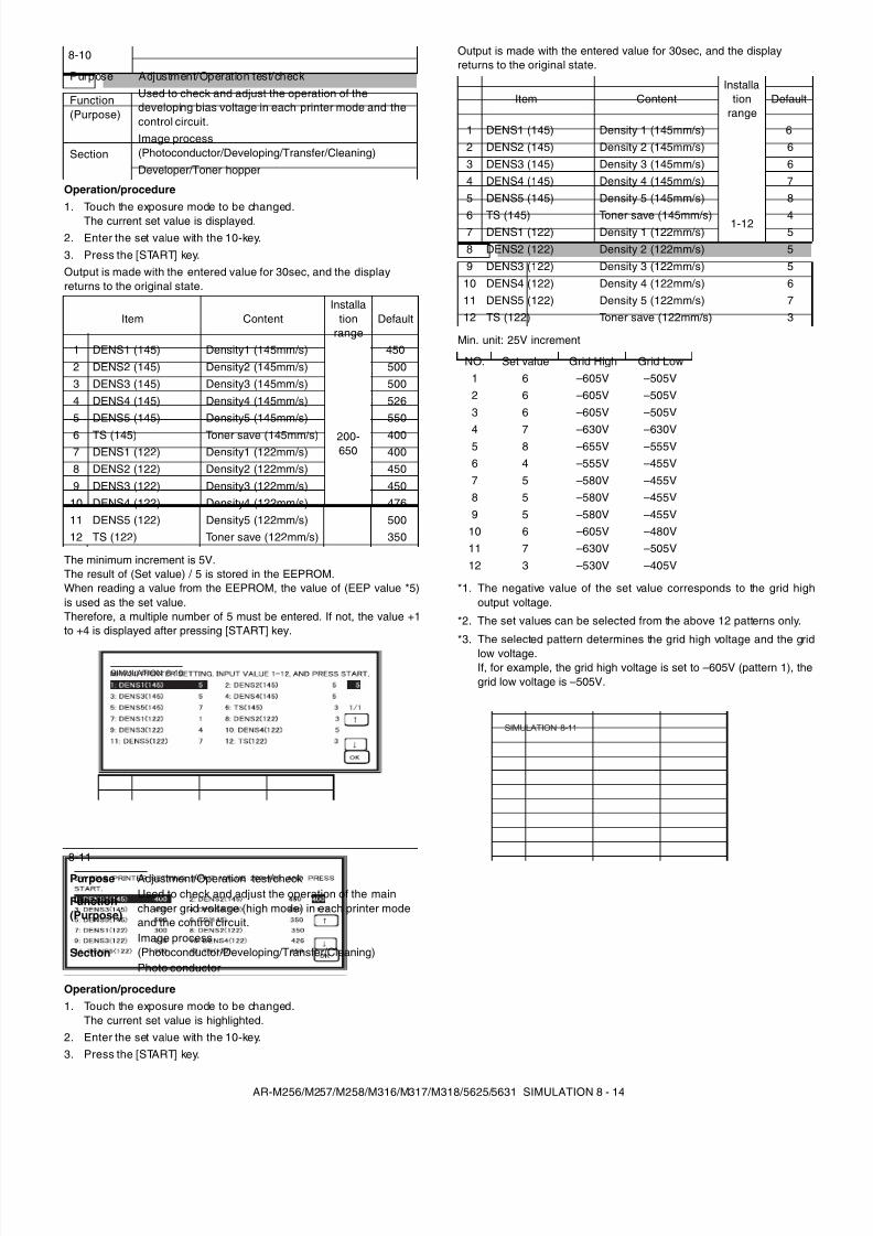
8/9/2019 AR-M318 SM
http://slidepdf.com/reader/full/ar-m318-sm 56/159
AR-M256/M257/M258/M316/M317/M318/5625/5631 SIMULATION 8 - 14
Operation/procedure1. Touch the exposure mode to be changed.
The current set value is displayed.2. Enter the set value with the 10-key.3. Press the [START] key.Output is made with the entered value for 30sec, and the displayreturns to the original state.
The minimum increment is 5V.The result of (Set value) / 5 is stored in the EEPROM.When reading a value from the EEPROM, the value of (EEP value *5)is used as the set value.Therefore, a multiple number of 5 must be entered. If not, the value +1to +4 is displayed after pressing [START] key.
Operation/procedure1. Touch the exposure mode to be changed.
The current set value is highlighted.2. Enter the set value with the 10-key.3. Press the [START] key.
Output is made with the entered value for 30sec, and the displayreturns to the original state.
Min. unit: 25V increment
*1. The negative value of the set value corresponds to the grid highoutput voltage.
*2. The set values can be selected from the above 12 patterns only.
*3. The selected pattern determines the grid high voltage and the gridlow voltage.If, for example, the grid high voltage is set to –605V (pattern 1), thegrid low voltage is –505V.
8-10
Purpose Adjustment/Operation test/check
Function(Purpose)
Used to check and adjust the operation of thedeveloping bias voltage in each printer mode and thecontrol circuit.
SectionImage process(Photoconductor/Developing/Transfer/Cleaning)Developer/Toner hopper
Item ContentInstalla
tionrange
Default
1 DENS1 (145) Density1 (145mm/s)
200-650
4502 DENS2 (145) Density2 (145mm/s) 5003 DENS3 (145) Density3 (145mm/s) 5004 DENS4 (145) Density4 (145mm/s) 5265 DENS5 (145) Density5 (145mm/s) 550
6 TS (145) Toner save (145mm/s) 4007 DENS1 (122) Density1 (122mm/s) 4008 DENS2 (122) Density2 (122mm/s) 4509 DENS3 (122) Density3 (122mm/s) 450
10 DENS4 (122) Density4 (122mm/s) 47611 DENS5 (122) Density5 (122mm/s) 50012 TS (122) Toner save (122mm/s) 350
8-11
Purpose Adjustment/Operation test/check
Function(Purpose)
Used to check and adjust the operation of the maincharger grid voltage (high mode) in each printer modeand the control circuit.
SectionImage process(Photoconductor/Developing/Transfer/Cleaning)Photo conductor
SIMULATION 8-10
Item ContentInstalla
tionrange
Default
1 DENS1 (145) Density 1 (145mm/s)
1-12
62 DENS2 (145) Density 2 (145mm/s) 63 DENS3 (145) Density 3 (145mm/s) 64 DENS4 (145) Density 4 (145mm/s) 75 DENS5 (145) Density 5 (145mm/s) 8
6 TS (145) Toner save (145mm/s) 47 DENS1 (122) Density 1 (122mm/s) 58 DENS2 (122) Density 2 (122mm/s) 59 DENS3 (122) Density 3 (122mm/s) 5
10 DENS4 (122) Density 4 (122mm/s) 611 DENS5 (122) Density 5 (122mm/s) 712 TS (122) Toner save (122mm/s) 3
NO. Set value Grid High Grid Low1 6 –605V –505V2 6 –605V –505V3 6 –605V –505V
4 7 –630V –630V5 8 –655V –555V6 4 –555V –455V7 5 –580V –455V8 5 –580V –455V9 5 –580V –455V
10 6 –605V –480V11 7 –630V –505V12 3 –530V –405V
SIMULATION 8-11
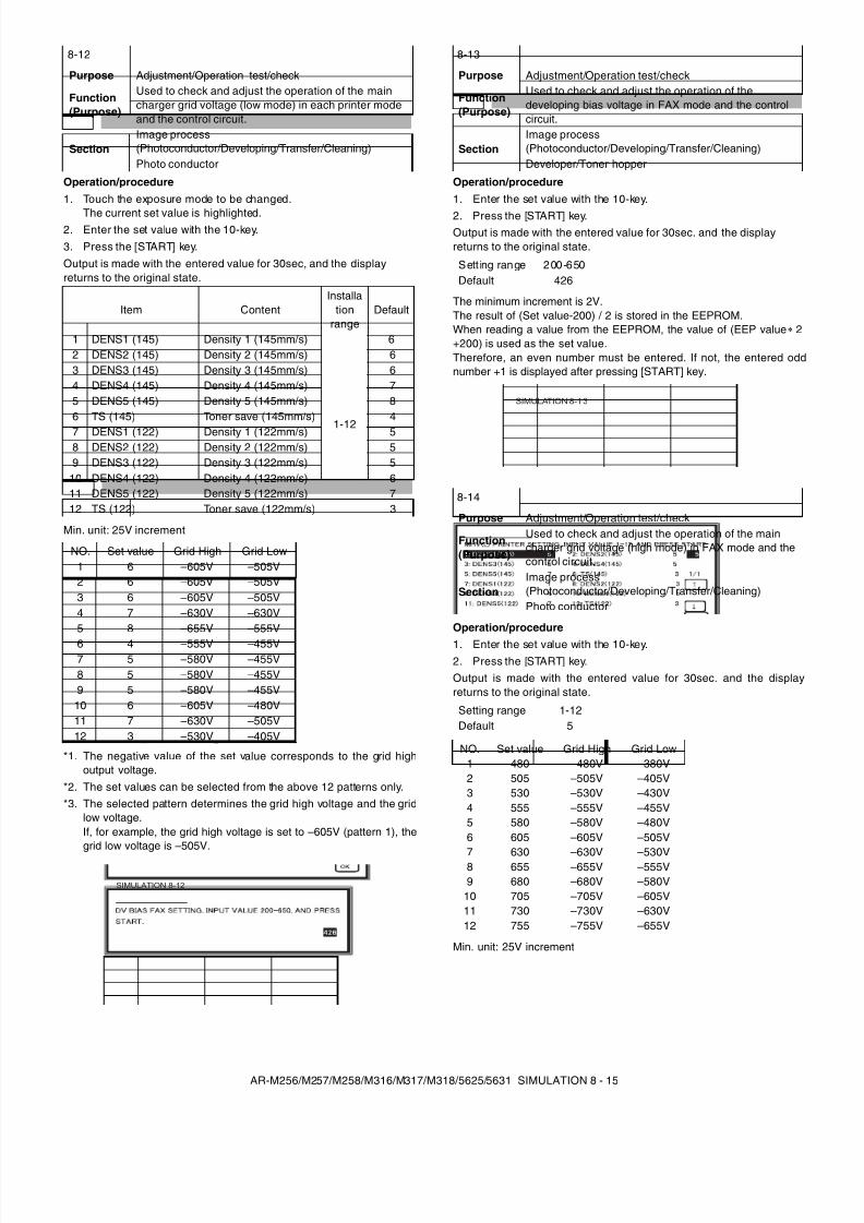
8/9/2019 AR-M318 SM
http://slidepdf.com/reader/full/ar-m318-sm 57/159
AR-M256/M257/M258/M316/M317/M318/5625/5631 SIMULATION 8 - 15
Operation/procedure1. Touch the exposure mode to be changed.
The current set value is highlighted.2. Enter the set value with the 10-key.3. Press the [START] key.Output is made with the entered value for 30sec, and the displayreturns to the original state.
Min. unit: 25V increment
*1. The negative value of the set value corresponds to the grid highoutput voltage.
*2. The set values can be selected from the above 12 patterns only.*3. The selected pattern determines the grid high voltage and the grid
low voltage.If, for example, the grid high voltage is set to –605V (pattern 1), thegrid low voltage is –505V.
Operation/procedure1. Enter the set value with the 10-key.
2. Press the [START] key.Output is made with the entered value for 30sec. and the displayreturns to the original state.
The minimum increment is 2V.The result of (Set value-200) / 2 is stored in the EEPROM.When reading a value from the EEPROM, the value of (EEP value 2+200) is used as the set value.Therefore, an even number must be entered. If not, the entered oddnumber +1 is displayed after pressing [START] key.
Operation/procedure
1. Enter the set value with the 10-key.2. Press the [START] key.Output is made with the entered value for 30sec. and the displayreturns to the original state.
Min. unit: 25V increment
8-12
Purpose Adjustment/Operation test/check
Function(Purpose)
Used to check and adjust the operation of the maincharger grid voltage (low mode) in each printer modeand the control circuit.
SectionImage process(Photoconductor/Developing/Transfer/Cleaning)Photo conductor
Item ContentInstalla
tionrange
Default
1 DENS1 (145) Density 1 (145mm/s)
1-12
62 DENS2 (145) Density 2 (145mm/s) 63 DENS3 (145) Density 3 (145mm/s) 64 DENS4 (145) Density 4 (145mm/s) 75 DENS5 (145) Density 5 (145mm/s) 86 TS (145) Toner save (145mm/s) 47 DENS1 (122) Density 1 (122mm/s) 58 DENS2 (122) Density 2 (122mm/s) 59 DENS3 (122) Density 3 (122mm/s) 5
10 DENS4 (122) Density 4 (122mm/s) 611 DENS5 (122) Density 5 (122mm/s) 712 TS (122) Toner save (122mm/s) 3
NO. Set value Grid High Grid Low1 6 –605V –505V2 6 –605V –505V3 6 –605V –505V4 7 –630V –630V5 8 –655V –555V
6 4 –555V –455V7 5 –580V –455V8 5 –580V –455V9 5 –580V –455V
10 6 –605V –480V11 7 –630V –505V12 3 –530V –405V
SIMULATION 8-12
8-13
Purpose Adjustment/Operation test/check
Function(Purpose)
Used to check and adjust the operation of thedeveloping bias voltage in FAX mode and the controlcircuit.
SectionImage process(Photoconductor/Developing/Transfer/Cleaning)Developer/Toner hopper
Sett ing range 200-650Default 426
8-14
Purpose Adjustment/Operation test/check
Function(Purpose)
Used to check and adjust the operation of the maincharger grid voltage (high mode) in FAX mode and thecontrol circuit.
SectionImage process(Photoconductor/Developing/Transfer/Cleaning)Photo conductor
Setting range 1-12Default 5
NO. Set value Grid High Grid Low1 480 –480V –380V2 505 –505V –405V3 530 –530V –430V4 555 –555V –455V5 580 –580V –480V6 605 –605V –505V
7 630 –630V –530V8 655 –655V –555V9 680 –680V –580V
10 705 –705V –605V11 730 –730V –630V12 755 –755V –655V
SIMULATION 8-1 3
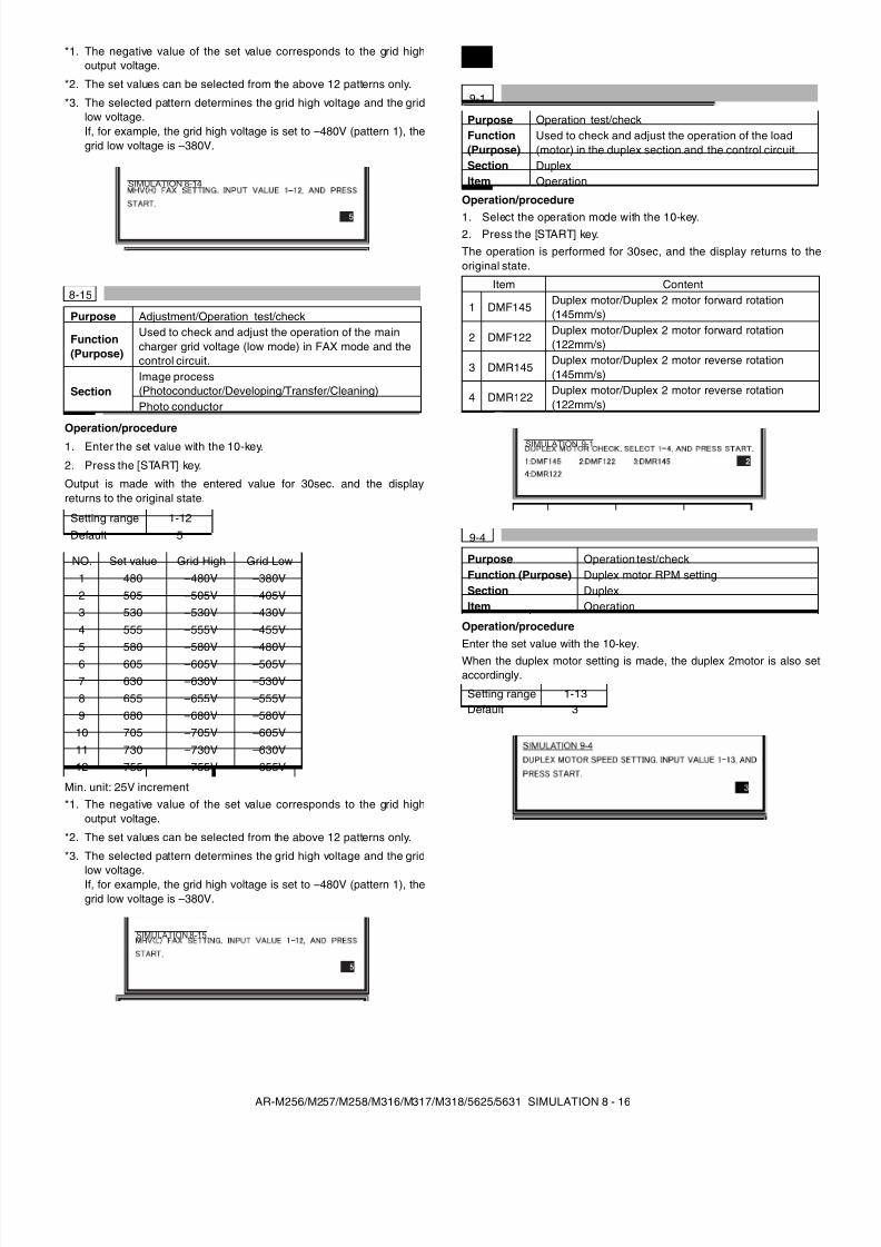
8/9/2019 AR-M318 SM
http://slidepdf.com/reader/full/ar-m318-sm 58/159
AR-M256/M257/M258/M316/M317/M318/5625/5631 SIMULATION 8 - 16
*1. The negative value of the set value corresponds to the grid highoutput voltage.
*2. The set values can be selected from the above 12 patterns only.
*3. The selected pattern determines the grid high voltage and the gridlow voltage.If, for example, the grid high voltage is set to –480V (pattern 1), thegrid low voltage is –380V.
Operation/procedure
1. Enter the set value with the 10-key.
2. Press the [START] key.
Output is made with the entered value for 30sec. and the displayreturns to the original state.
Min. unit: 25V increment*1. The negative value of the set value corresponds to the grid high
output voltage.
*2. The set values can be selected from the above 12 patterns only.
*3. The selected pattern determines the grid high voltage and the grid
low voltage.If, for example, the grid high voltage is set to –480V (pattern 1), thegrid low voltage is –380V.
Operation/procedure
1. Select the operation mode with the 10-key.2. Press the [START] key.The operation is performed for 30sec, and the display returns to theoriginal state.
Operation/procedureEnter the set value with the 10-key.When the duplex motor setting is made, the duplex 2motor is also setaccordingly.
8-15
Purpose Adjustment/Operation test/check
Function(Purpose)
Used to check and adjust the operation of the maincharger grid voltage (low mode) in FAX mode and thecontrol circuit.
SectionImage process(Photoconductor/Developing/Transfer/Cleaning)Photo conductor
Setting range 1-12Default 5
NO. Set value Grid High Grid Low1 480 –480V –380V2 505 –505V –405V3 530 –530V –430V4 555 –555V –455V5 580 –580V –480V6 605 –605V –505V7 630 –630V –530V8 655 –655V –555V9 680 –680V –580V
10 705 –705V –605V11 730 –730V –630V12 755 –755V –655V
SIMULATION 8-14
SIMULATION 8-15
9
9-1
Purpose Operation test/checkFunction(Purpose)
Used to check and adjust the operation of the load(motor) in the duplex section and the control circuit.
Section DuplexItem Operation
Item Content
1 DMF145Duplex motor/Duplex 2 motor forward rotation(145mm/s)
2 DMF122Duplex motor/Duplex 2 motor forward rotation(122mm/s)
3 DMR145Duplex motor/Duplex 2 motor reverse rotation(145mm/s)
4 DMR122Duplex motor/Duplex 2 motor reverse rotation(122mm/s)
9-4
Purpose Operation test/checkFunction (Purpose) Duplex motor RPM settingSection DuplexItem Operation
Setting range 1-13Default 3
SIMULATION 9-1
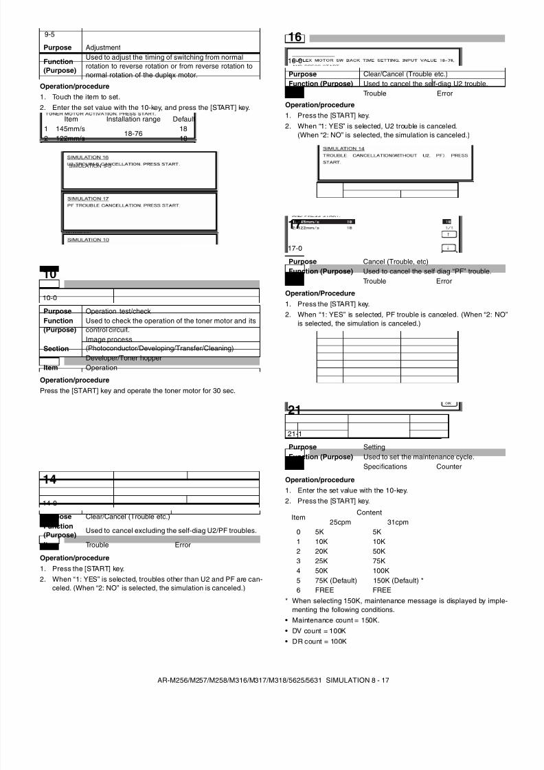
8/9/2019 AR-M318 SM
http://slidepdf.com/reader/full/ar-m318-sm 59/159
AR-M256/M257/M258/M316/M317/M318/5625/5631 SIMULATION 8 - 17
Operation/procedure1. Touch the item to set.2. Enter the set value with the 10-key, and press the [START] key.
Operation/procedurePress the [START] key and operate the toner motor for 30 sec.
Operation/procedure1. Press the [START] key.2. When “1: YES” is selected, troubles other than U2 and PF are can-
celed. (When “2: NO” is selected, the simulation is canceled.)
Operation/procedure1. Press the [START] key.2. When “1: YES” is selected, U2 trouble is canceled.
(When “2: NO” is selected, the simulation is canceled.)
Operation/Procedure1. Press the [START] key.2. When “1: YES” is selected, PF trouble is canceled. (When “2: NO”
is selected, the simulation is canceled.)
Operation/procedure1. Enter the set value with the 10-key.2. Press the [START] key.
* When selecting 150K, maintenance message is displayed by imple-menting the following conditions.
• Maintenance count = 150K.• DV count = 100K• DR count = 100K
9-5
Purpose Adjustment
Function(Purpose)
Used to adjust the timing of switching from normalrotation to reverse rotation or from reverse rotation tonormal rotation of the duplex motor.
Item Installation range Default1 145mm/s
18-7618
2 122mm/s 18
10
10-0
Purpose Operation test/checkFunction(Purpose)
Used to check the operation of the toner motor and itscontrol circuit.
SectionImage process(Photoconductor/Developing/Transfer/Cleaning)Developer/Toner hopper
Item Operation
14
14-0
Purpose Clear/Cancel (Trouble etc.)Function(Purpose)
Used to cancel excluding the self-diag U2/PF troubles.
Item Trouble Error
SIMULATION 9-5
16
16-0
Purpose Clear/Cancel (Trouble etc.)Function (Purpose) Used to cancel the self-diag U2 trouble.Item Trouble Error
17
17-0
Purpose Cancel (Trouble, etc)
Function (Purpose) Used to cancel the self diag “PF” trouble.Item Trouble Error
21
21-1
Purpose SettingFunction (Purpose) Used to set the maintenance cycle.Item Specifications Counter
ItemContent
25cpm 31cpm0 5K 5K1 10K 10K2 20K 50K3 25K 75K4 50K 100K5 75K (Default) 150K (Default) *6 FREE FREE
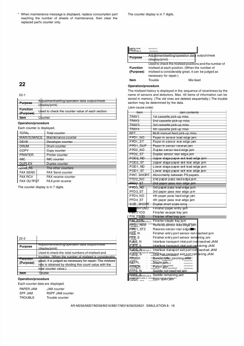
8/9/2019 AR-M318 SM
http://slidepdf.com/reader/full/ar-m318-sm 60/159
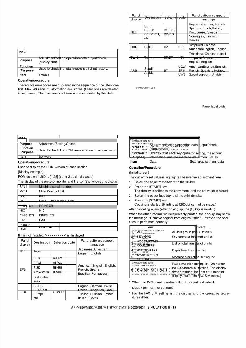
8/9/2019 AR-M318 SM
http://slidepdf.com/reader/full/ar-m318-sm 61/159
AR-M256/M257/M258/M316/M317/M318/5625/5631 SIMULATION 8 - 19
Operation/procedureThe trouble error codes are displayed in the sequence of the latest onefirst. Max. 40 items of information are stored. (Older ones are deletedin sequence.) The machine condition can be estimated by this data.
Operation/procedureUsed to display the ROM version of each section.[Display example]ROM version 1.250 → [1.25] (up to 2 decimal places)
The display of the protocol monitor and the soft SW follows this display.
If it is not installed, “- - - - - - - - - -” is displayed.
Operation/Procedure(Initial screen)The currently set value is highlighted beside the adjustment item.
1. Select the adjustment item with the 10-key.2. Press the [START] key.
The display is shifted to the copy menu and the set value is stored.3. Select the paper feed tray and the print density.4. Press the [START] key.
Copying is started. (Printing at 1200dpi cannot be made.)After canceling a jam (After picking up, the [C] key is invalid.)When the other information is repeatedly printed, the display may showthe message, “Remove original from original table.” However, the oper-ation is performed normally.
* When the IMC board is not installed, key input is disabled.
* Duplex print cannot be made.
* For the FAX SIM setting list, the display and the operating proce-dures differ.
22-4
PurposeAdjustment/setting/operation data output/check(display/print)
Function(Purpose)
Used to check the total trouble (self diag) history.
Item Trouble
22-5
Purpose Adjustment/Setting/CheckFunction(Purpose)
Used to check the ROM version of each unit (section).
Item Software
S/N Machine serial numberMCU Main Control UnitIMC IMCOPE Panel + Panel label codePRINTER PRINTERNIC NICFINISHER FINISHERFAX FAXPUNCHUNIT
Punch unit
Paneldisplay Destination Selection code
Panel software supportlanguage
JPN JapanJapanese, AmericanEnglish, English
EFS
SEC AJ/AM
American English, English,French, Spanish,Brazilian Portuguese
SECL AL/ACSUK BK/BBSCA/SCNZ BA/BNDistributorarea
EEU
SEEG/ SEA/EastEurope,etc.
GG/GD
English, German, Polish,Czech, Hungarian, Greek,Turkish, Russian, French,Italian, Slovak
NEU
SEF/ SEES/ SEIS/SEN,etc.
BG/DG/ BD/DD
English, German, French,Spanish, Dutch, Italian,Portuguese, Swedish,Norwegian, Finnish,Danish
CHN SOCC BZ UE5Simplified Chinese,American English, English
TWN Taiwan BE/BT UT1Traditional Chinese (Localsupport), AmericanEnglish, English
ARBSaudiArabia BT
UQ2/ SF1/ UW2
American English, English,French, Spanish, Hebrew (Local support), Arabic
22-6
PurposeAdjustment/setting/operation data output/check(display/print)
Function(Purpose)
Used to print each key operator setting, the accountinformation, and the machine adjustment values.
Item Data Setting/adjustment data
Item Content1 ALL All lists group print (Default)2 KEY OPE Key operator information list
3ACCOUNTINGCOUNTERS List of total number of prints
4 AUDITOR NO. Department number list
5MACHINE SIMSETTING Machine simulation setting list
6 FAX SIM SETTING*1
FAX simulation setting list (Only whenthe FAX board is installed. The displaydoes not go to the print data transferdisplay, but to the FAX SIM menu.)
Paneldisplay
Destination Selection code Panel software supportlanguage
SIMULATION 22-5
Panel label code
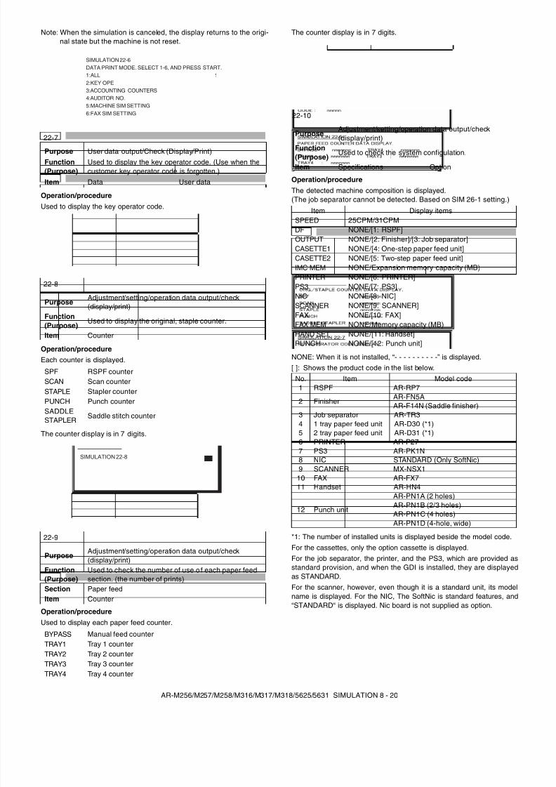
8/9/2019 AR-M318 SM
http://slidepdf.com/reader/full/ar-m318-sm 62/159
AR-M256/M257/M258/M316/M317/M318/5625/5631 SIMULATION 8 - 20
Note: When the simulation is canceled, the display returns to the origi-nal state but the machine is not reset.
Operation/procedureUsed to display the key operator code.
Operation/procedureEach counter is displayed.
The counter display is in 7 digits.
Operation/procedureUsed to display each paper feed counter.
The counter display is in 7 digits.
Operation/procedureThe detected machine composition is displayed.(The job separator cannot be detected. Based on SIM 26-1 setting.)
NONE: When it is not installed, “- - - - - - - - - -” is displayed.[ ]: Shows the product code in the list below.
*1: The number of installed units is displayed beside the model code.For the cassettes, only the option cassette is displayed.For the job separator, the printer, and the PS3, which are provided asstandard provision, and when the GDI is installed, they are displayedas STANDARD.For the scanner, however, even though it is a standard unit, its modelname is displayed. For the NIC, The SoftNic is standard features, and“STANDARD“ is displayed. Nic board is not supplied as option.
22-7Purpose User data output/Check (Display/Print)Function(Purpose)
Used to display the key operator code. (Use when thecustomer key operator code is forgotten.)
Item Data User data
22-8
PurposeAdjustment/setting/operation data output/check(display/print)
Function(Purpose)
Used to display the original, staple counter.
Item Counter
SPF RSPF counterSCAN Scan counterSTAPLE Stapler counterPUNCH Punch counter
SADDLESTAPLER Saddle stitch counter
22-9
Purpose Adjustment/setting/operation data output/check(display/print)
Function(Purpose)
Used to check the number of use o f each paper feedsection. (the number of prints)
Section Paper feedItem Counter
BYPASS Manual feed counterTRAY1 Tray 1 counterTRAY2 Tray 2 counterTRAY3 Tray 3 counterTRAY4 Tray 4 counter
SIMULATION 22-6DATA PRINT MODE. SELECT 1-6, AND PRESS START.1:ALL2:KEY OPE3:ACCOUNTING COUNTERS4:AUDITOR NO.5:MACHINE SIM SETTING6:FAX SIM SETTING
1
SIMULATION 22-8
22-10
PurposeAdjustment/setting/operation data output/check
(display/print)Function(Purpose)
Used to check the system configulation.
Item Specifications Option
Item Display itemsSPEED 25CPM/31CPMDF NONE/[1: RSPF]OUTPUT NONE/[2: Finisher]/[3: Job separator]CASETTE1 NONE/[4: One-step paper feed unit]CASETTE2 NONE/[5: Two-step paper feed unit]IMC MEM NONE/Expansion memory capacity (MB)PRINTER NONE/[6: PRINTER]PS3 NONE/[7: PS3]NIC NONE/[8: NIC]SCANNER NONE/[9: SCANNER]FAX NONE/[10: FAX]FAX MEM NONE/Memory capacity (MB)HAND SET NONE/[11: Handset]PUNCH NONE/[12: Punch unit]
No. Item Model code1 RSPF AR-RP7
2 FinisherAR-FN5AAR-F14N (Saddle finisher)
3 Job separator AR-TR34 1 tray paper feed unit AR-D30 (*1)5 2 tray paper feed unit AR-D31 (*1)6 PRINTER AR-P277 PS3 AR-PK1N8 NIC STANDARD (Only SoftNic)9 SCANNER MX-NSX1
10 FAX AR-FX711 Handset AR-HN4
12 Punch unit
AR-PN1A (2 holes)AR-PN1B (2/3 holes)AR-PN1C (4 holes)AR-PN1D (4-hole, wide)
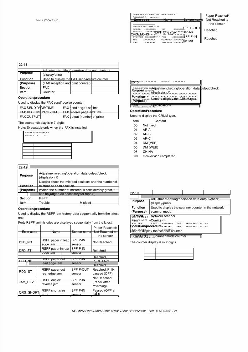
8/9/2019 AR-M318 SM
http://slidepdf.com/reader/full/ar-m318-sm 63/159
AR-M256/M257/M258/M316/M317/M318/5625/5631 SIMULATION 8 - 21
Operation/procedureUsed to display the FAX send/receive counter.
The counter display is in 7 digits.Note: Executable only when the FAX is installed.
Operation/procedureUsed to display the RSPF jam history data sequentially from the latestone.Forty RSPF jam histories are displayed sequentially from the latest.
Operation/ProcedureUsed to display the CRUM type.
Operation/procedureUsed to display the scanner counter.
The counter display is in 7 digits.
22-11
PurposeAdjustment/setting/operation data output/check(display/print)
Function(Purpose)
Used to display the FAX send/receive counter(FAX reception and print counter).
Section FAXItem Counter
FAX SEND PAGE/TIME FAX send page and timeFAX RECEIVE PAGE/TIME FAX receive page and timeFAX OUTPUT FAX output (number of print)
22-12
PurposeAdjustment/setting/operation data output/check(display/print)
Function(Purpose)
Used to check the misfeed positions and the number ofmisfeed at each position.(When the number of misfeed is considerably great, itcan be judged as necessary for repair.)
Section RSPFItem Trouble Misfeed
Error code Name Sensor namePaper Reached/ Not Reached to
the sensor
DFD_NDRSPF paper in leadedge jam
SPF P-INsensor
Not Reached
DFD_STRSPF paper in rearedge jam
SPF P-INsensor
Reached
RDD_NDRSPF paper outlead edge jam
SPF P-INsensor
Reached,P_OUT NotReached
RDD_STRSPF paper outrear edge jam
SPF P-OUTsensor
Reached, P_INpassed (OFF)
JAM_REVRSPF duplexreverse jam
SPF P-INsensor
Not Reached(Paper afterreversing)
ORG_SHORT RSPF short sizeerror
SPF P-INsensor
Passed (OFF atJAM)
SIMULATION 22-10
ORG_LONG RSPF long sizeerror
SPF P-OUTsensor
Reached
SPF P-INsensor
Reached
22-13
PurposeAdjustment/setting/operation data output/check(display/print)
Function(Purpose)
Used to display the CRUM type.
Item Specifications
Item Content00 Not fixed.01 AR-A02 AR-B03 AR-C04 DM (VER)05 DM (WEB)06 CHINA99 Conversion completed.
22-19
PurposeAdjustment/setting/operation data output/check(display/print)
Function(Purpose)
Used to display the scanner counter in the networkscanner mode.
Section Network scannerItem Counter
SCANMODE Scanner mode counter
Error code Name Sensor namePaper Reached/ Not Reached to
the sensor
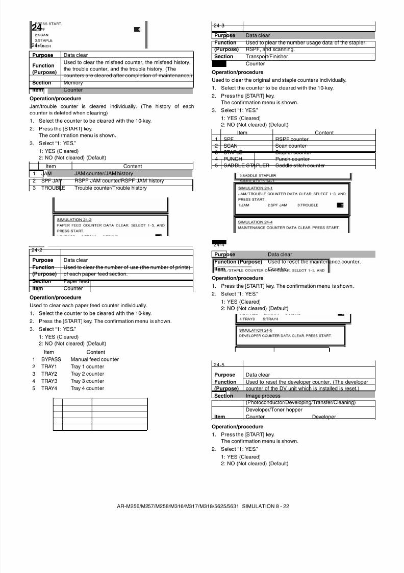
8/9/2019 AR-M318 SM
http://slidepdf.com/reader/full/ar-m318-sm 64/159
AR-M256/M257/M258/M316/M317/M318/5625/5631 SIMULATION 8 - 22
Operation/procedureJam/trouble counter is cleared individually. (The history of eachcounter is deleted when c learing)1. Select the counter to be cleared with the 10-key.2. Press the [START] key.
The confirmation menu is shown.3. Select “1: YES.”
1: YES (Cleared)2: NO (Not cleared) (Default)
Operation/procedureUsed to clear each paper feed counter individually.1. Select the counter to be cleared with the 10-key.2. Press the [START] key. The confirmation menu is shown.3. Select “1: YES.”
1: YES (Cleared)2: NO (Not cleared) (Default)
Operation/procedureUsed to clear the original and staple counters individually.1. Select the counter to be cleared with the 10-key.2. Press the [START] key.
The confirmation menu is shown.3. Select “1: YES.”
1: YES (Cleared)2: NO (Not cleared) (Default)
Operation/procedure1. Press the [START] key. The confirmation menu is shown.2. Select “1: YES.”
1: YES (Cleared)2: NO (Not cleared) (Default)
Operation/procedure1. Press the [START] key.
The confirmation menu is shown.2. Select “1: YES.”
1: YES (Cleared)2: NO (Not cleared) (Default)
24
24-1
Purpose Data clear
Function(Purpose)
Used to clear the misfeed counter, the misfeed history,the trouble counter, and the trouble history. (Thecounters are cleared after completion of maintenance.)
Section MemoryItem Counter
Item Content1 JAM JAM counter/JAM history2 SPF JAM RSPF JAM counter/RSPF JAM history3 TROUBLE Trouble counter/Trouble history
24-2
Purpose Data clearFunction(Purpose)
Used to clear the number of use (the number of prints)of each paper feed section.
Section Paper feedItem Counter
Item Content1 BYPASS Manual feed counter2 TRAY1 Tray 1 counter3 TRAY2 Tray 2 counter4 TRAY3 Tray 3 counter5 TRAY4 Tray 4 counter
24-3
Purpose Data clearFunction(Purpose)
Used to clear the number usage data of the stapler,RSPF, and scanning.
Section Transport/FinisherItem Counter
Item Content1 SPF RSPF counter2 SCAN Scan counter3 STAPLE Stapler counter4 PUNCH Punch counter5 SADDLE STAPLER Saddle stitch counter
24-4
Purpose Data clearFunction (Purpose) Used to reset the maintenance counter.Item Counter
24-5
Purpose Data clearFunction(Purpose)
Used to reset the developer counter. (The developercounter of the DV unit which is installed is reset.)
Section Image process(Photoconductor/Developing/Transfer/Cleaning)Developer/Toner hopper
Item Counter Developer
SIMULATION 24-3
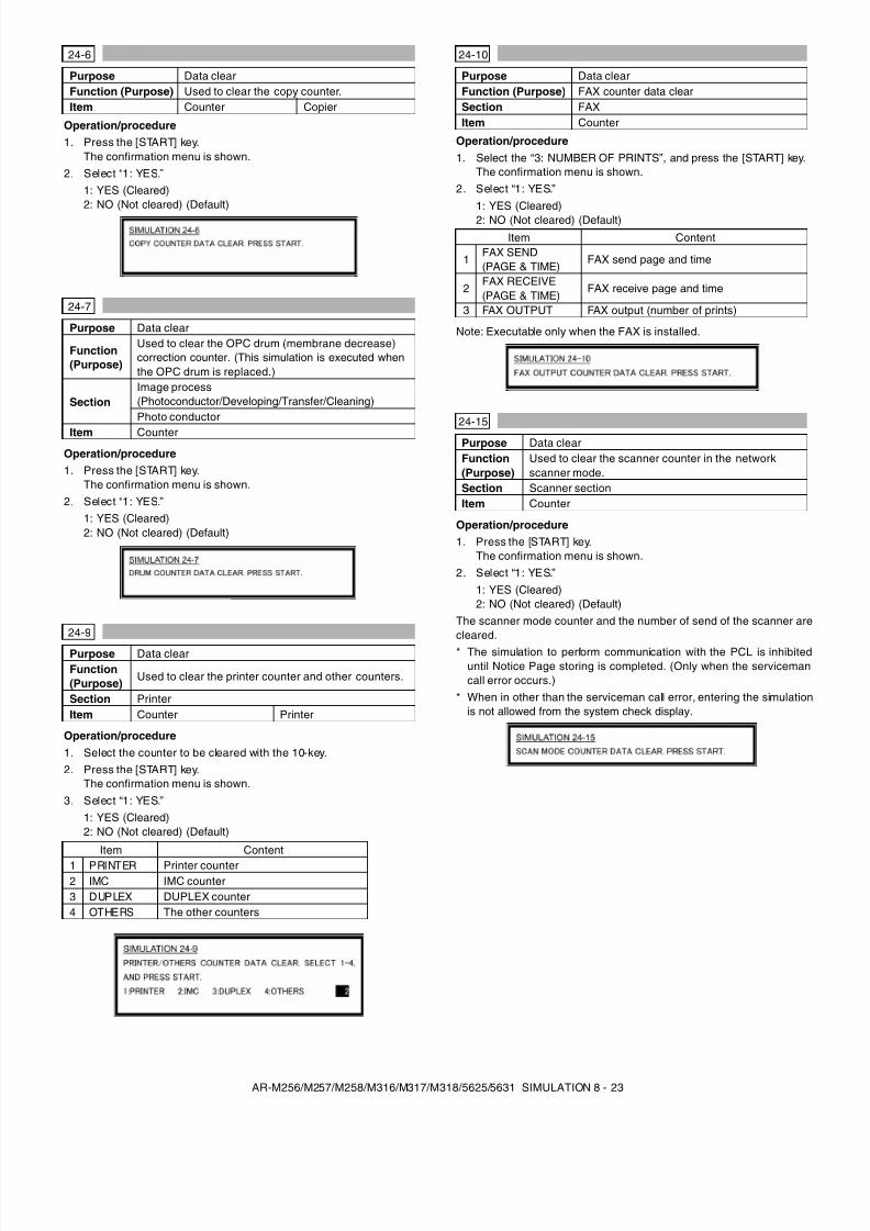
8/9/2019 AR-M318 SM
http://slidepdf.com/reader/full/ar-m318-sm 65/159
AR-M256/M257/M258/M316/M317/M318/5625/5631 SIMULATION 8 - 23
Operation/procedure1. Press the [START] key.
The confirmation menu is shown.2. Select “1: YES.”
1: YES (Cleared)2: NO (Not cleared) (Default)
Operation/procedure1. Press the [START] key.
The confirmation menu is shown.2. Select “1: YES.”
1: YES (Cleared)2: NO (Not cleared) (Default)
Operation/procedure1. Select the counter to be cleared with the 10-key.2. Press the [START] key.
The confirmation menu is shown.3. Select “1: YES.”
1: YES (Cleared)2: NO (Not cleared) (Default)
Operation/procedure1. Select the “3: NUMBER OF PRINTS”, and press the [START] key.
The confirmation menu is shown.2. Select “1: YES.”
1: YES (Cleared)2: NO (Not cleared) (Default)
Note: Executable only when the FAX is installed.
Operation/procedure1. Press the [START] key.
The confirmation menu is shown.2. Select “1: YES.”
1: YES (Cleared)2: NO (Not cleared) (Default)
The scanner mode counter and the number of send of the scanner arecleared.* The simulation to perform communication with the PCL is inhibited
until Notice Page storing is completed. (Only when the servicemancall error occurs.)
* When in other than the serviceman call error, entering the simulationis not allowed from the system check display.
24-6
Purpose Data clearFunction (Purpose) Used to clear the copy counter.Item Counter Copier
24-7
Purpose Data clear
Function(Purpose)
Used to clear the OPC drum (membrane decrease)correction counter. (This simulation is executed whenthe OPC drum is replaced.)
SectionImage process(Photoconductor/Developing/Transfer/Cleaning)Photo conductor
Item Counter
24-9
Purpose Data clearFunction(Purpose)
Used to clear the printer counter and other counters.
Section PrinterItem Counter Printer
Item Content1 PRINTER Printer counter2 IMC IMC counter3 DUPLEX DUPLEX counter4 OTHERS The other counters
24-10
Purpose Data clearFunction (Purpose) FAX counter data clearSection FAXItem Counter
Item Content
1FAX SEND(PAGE & TIME)
FAX send page and time
2FAX RECEIVE(PAGE & TIME)
FAX receive page and time
3 FAX OUTPUT FAX output (number of prints)
24-15
Purpose Data clearFunction(Purpose)
Used to clear the scanner counter in the networkscanner mode.
Section Scanner sectionItem Counter
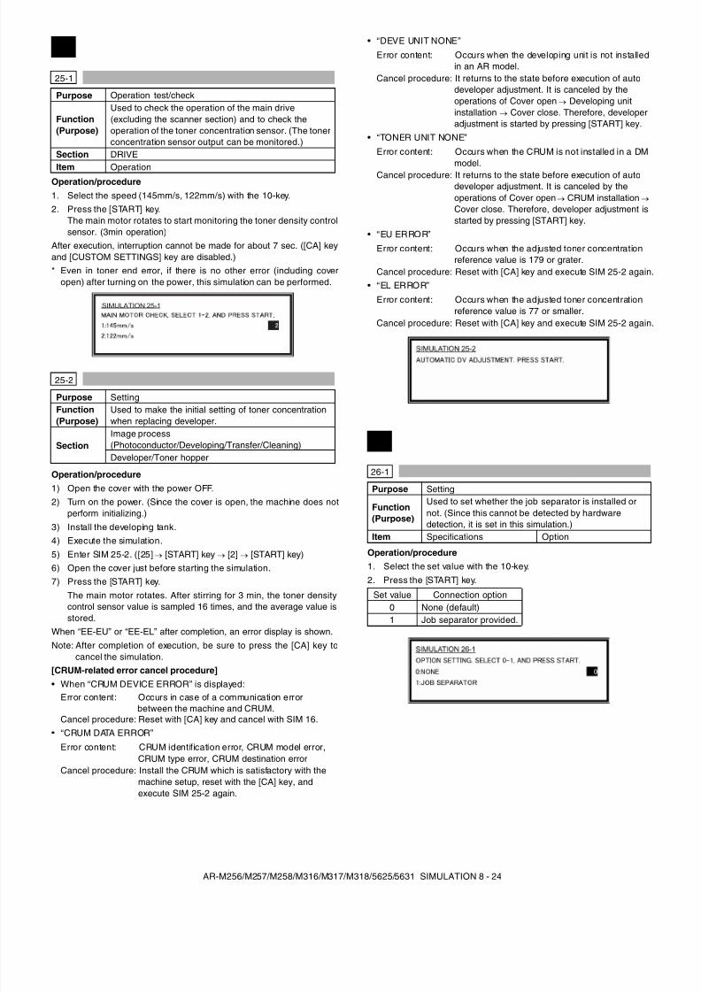
8/9/2019 AR-M318 SM
http://slidepdf.com/reader/full/ar-m318-sm 66/159
AR-M256/M257/M258/M316/M317/M318/5625/5631 SIMULATION 8 - 24
Operation/procedure1. Select the speed (145mm/s, 122mm/s) with the 10-key.2. Press the [START] key.
The main motor rotates to start monitoring the toner density controlsensor. (3min operation)
After execution, interruption cannot be made for about 7 sec. ([CA] keyand [CUSTOM SETTINGS] key are disabled.)* Even in toner end error, if there is no other error (including cover
open) after turning on the power, this simulation can be performed.
Operation/procedure1) Open the cover with the power OFF.2) Turn on the power. (Since the cover is open, the machine does not
perform initializing.)3) Install the developing tank.4) Execute the simulation.5) Enter SIM 25-2. ([25] → [START] key → [2] → [START] key)6) Open the cover just before starting the simulation.7) Press the [START] key.
The main motor rotates. After stirring for 3 min, the toner densitycontrol sensor value is sampled 16 times, and the average value isstored.
When “EE-EU” or “EE-EL” after completion, an error display is shown.Note: After completion of execution, be sure to press the [CA] key to
cancel the simulation.[CRUM-related error cancel procedure]• When “CRUM DEVICE ERROR” is displayed:
• “CRUM DATA ERROR”
• “DEVE UNIT NONE”
• “TONER UNIT NONE”
• “EU ERROR”
• “EL ERROR”
Operation/procedure1. Select the set value with the 10-key.2. Press the [START] key.
25
25-1
Purpose Operation test/check
Function(Purpose)
Used to check the operation of the main drive(excluding the scanner section) and to check theoperation of the toner concentration sensor. (The tonerconcentration sensor output can be monitored.)
Section DRIVEItem Operation
25-2
Purpose SettingFunction(Purpose)
Used to make the initial setting of toner concentrationwhen replacing developer.
SectionImage process(Photoconductor/Developing/Transfer/Cleaning)Developer/Toner hopper
Error content: Occurs in case of a communication errorbetween the machine and CRUM.
Cancel procedure: Reset with [CA] key and cancel with SIM 16.
Error content: CRUM identification error, CRUM model error,CRUM type error, CRUM destination error
Cancel procedure: Install the CRUM which is satisfactory with themachine setup, reset with the [CA] key, andexecute SIM 25-2 again.
SIMULATION 25-1
Error content: Occurs when the developing unit is not installedin an AR model.
Cancel procedure: It returns to the state before execution of autodeveloper adjustment. It is canceled by theoperations of Cover open → Developing unitinstallation → Cover close. Therefore, developeradjustment is started by pressing [START] key.
Error content: Occurs when the CRUM is not installed in a DMmodel.
Cancel procedure: It returns to the state before execution of autodeveloper adjustment. It is canceled by theoperations of Cover open → CRUM installation → Cover close. Therefore, developer adjustment isstarted by pressing [START] key.
Error content: Occurs when the adjusted toner concentrationreference value is 179 or grater.
Cancel procedure: Reset with [CA] key and execute SIM 25-2 again.
Error content: Occurs when the adjusted toner concentrationreference value is 77 or smaller.
Cancel procedure: Reset with [CA] key and execute SIM 25-2 again.
26
26-1
Purpose Setting
Function
(Purpose)
Used to set whether the job separator is installed ornot. (Since this cannot be detected by hardwaredetection, it is set in this simulation.)
Item Specifications Option
Set value Connection option0 None (default)1 Job separator provided.
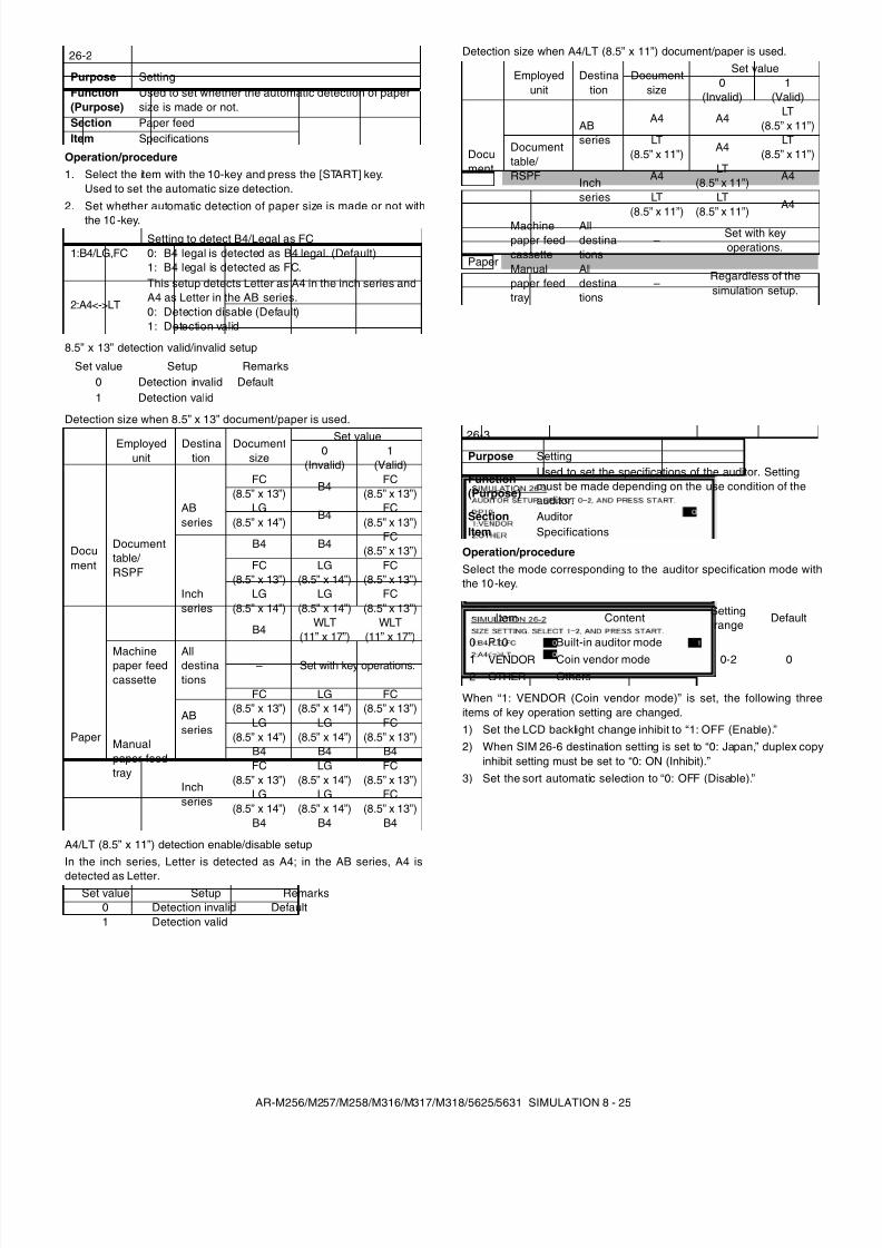
8/9/2019 AR-M318 SM
http://slidepdf.com/reader/full/ar-m318-sm 67/159
AR-M256/M257/M258/M316/M317/M318/5625/5631 SIMULATION 8 - 25
Operation/procedure1. Select the item with the 10-key and press the [START] key.
Used to set the automatic size detection.2. Set whether automatic detection of paper size is made or not with
the 10-key.
8.5” x 13” detection valid/invalid setup
Detection size when 8.5” x 13” document/paper is used.
A4/LT (8.5” x 11”) detection enable/disable setupIn the inch series, Letter is detected as A4; in the AB series, A4 is
detected as Letter.
Detection size when A4/LT (8.5” x 11”) document/paper is used.
Operation/procedureSelect the mode corresponding to the auditor specification mode withthe 10-key.
When “1: VENDOR (Coin vendor mode)” is set, the following threeitems of key operation setting are changed.1) Set the LCD backlight change inhibit to “1: OFF (Enable).”2) When SIM 26-6 destination setting is set to “0: Japan,” duplex copy
inhibit setting must be set to “0: ON (Inhibit).”3) Set the sort automatic selection to “0: OFF (Disable).”
26-2
Purpose SettingFunction(Purpose)
Used to set whether the automatic detection of papersize is made or not.
Section Paper feedItem Specifications
1:B4/LG,FCSetting to detect B4/Legal as FC0: B4 legal is detected as B4 legal. (Default)1: B4 legal is detected as FC.
2:A4<->LT
This setup detects Letter as A4 in the inch series andA4 as Letter in the AB series.0: Detection disable (Default)1: Detection valid
Set value Setup Remarks0 Detection invalid Default1 Detection valid
Employedunit
Destination
Documentsize
Set value0
(Invalid)1
(Valid)
Document
Documenttable/ RSPF
ABseries
FC(8.5” x 13”)
B4FC
(8.5” x 13”)LG
(8.5” x 14”)B4
FC(8.5” x 13”)
B4 B4FC
(8.5” x 13”)
Inchseries
FC(8.5” x 13”)
LG(8.5” x 14”)
FC(8.5” x 13”)
LG(8.5” x 14”)
LG(8.5” x 14”)
FC(8.5” x 13”)
B4WLT
(11” x 17”)WLT
(11” x 17”)
Paper
Machinepaper feedcassette
Alldestinations
– Set with key operations.
Manualpaper feedtray
ABseries
FC(8.5” x 13”)
LG(8.5” x 14”)
FC(8.5” x 13”)
LG(8.5” x 14”)
LG(8.5” x 14”)
FC(8.5” x 13”)
B4 B4 B4
Inchseries
FC(8.5” x 13”)
LG(8.5” x 14”)
FC(8.5” x 13”)
LG(8.5” x 14”)
LG(8.5” x 14”)
FC(8.5” x 13”)
B4 B4 B4
Set value Setup Remarks0 Detection invalid Default1 Detection valid
Employedunit
Destination
Documentsize
Set value0
(Invalid)1
(Valid)
Document
Documenttable/ RSPF
ABseries
A4 A4 LT(8.5” x 11”)
LT(8.5” x 11”)
A4LT
(8.5” x 11”)
Inchseries
A4LT
(8.5” x 11”) A4
LT(8.5” x 11”)
LT(8.5” x 11”)
A4
Paper
Machinepaper feedcassette
Alldestinations
–Set with keyoperations.
Manualpaper feedtray
Alldestinations
–Regardless of thesimulation setup.
26-3Purpose Setting
Function(Purpose)
Used to set the specifications of the auditor. Settingmust be made depending on the use condition of theauditor.
Section AuditorItem Specifications
Item Content Settingrange
Default
0 P10 Built-in auditor mode
0-2 01 VENDOR Coin vendor mode2 OTHER Others
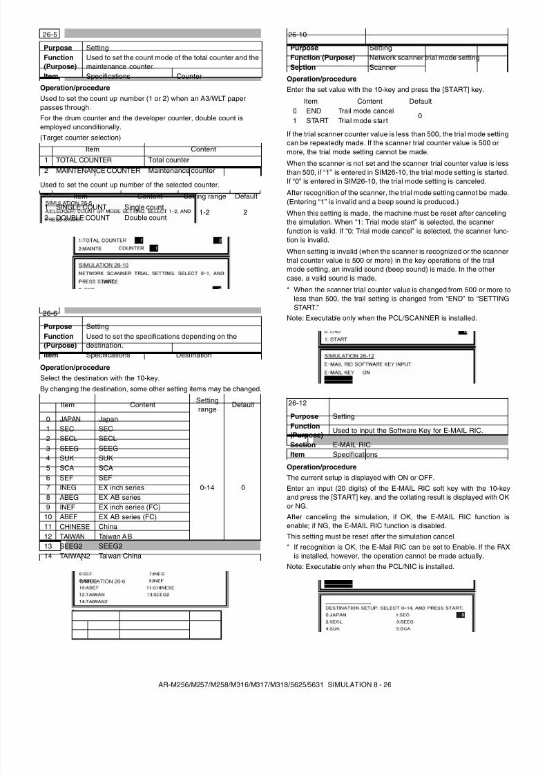
8/9/2019 AR-M318 SM
http://slidepdf.com/reader/full/ar-m318-sm 68/159
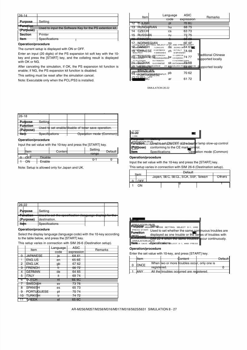
8/9/2019 AR-M318 SM
http://slidepdf.com/reader/full/ar-m318-sm 69/159
AR-M256/M257/M258/M316/M317/M318/5625/5631 SIMULATION 8 - 27
Operation/procedureThe current setup is displayed with ON or OFF.Enter an input (20 digits) of the PS expansion kit soft key with the 10-key and press the [START] key, and the collating result is displayedwith OK or NG.After canceling the simulation, if OK, the PS expansion kit function isenable; if NG, the PS expansion kit function is disabled.This setting must be reset after the simulation cancel.Note: Executable only when the PCL/PS3 is installed.
Operation/procedureInput the set value with the 10-key and press the [START] key.
Note: Setup is allowed only for Japan and UK.
Operation/procedureSelect the display language (language code) with the 10-key accordingto the table below, and press the [START] key.This setup varies in connection with SIM 26-6 (Destination setup).
Operation/procedureInput the set value with the 10-key and press the [START] key.This setup varies in connection with SIM 26-6 (Destination setup).
Operation/procedureEnter the set value with 10-key, and press [START] key.
26-14
Purpose SettingFunction(Purpose)
Used to input the Software Key for the PS extention kit.
Section PrinterItem Specifications
26-18
Purpose SettingFunction(Purpose)
Used to set enable/disable of toner save operation.
Item Specifications Operation mode (Common)
Item ContentSettingrange
Default
0 OFF Disable 0-1 01 ON Enable
26-22
Purpose SettingFunction(Purpose)
Used to set the specification (language display) for thedestination.
Item Specifications
ItemLanguage
codeASIC
expressionRemarks
0 JAPANESE ja 6A 611 ENG.US en 65 6E2 ENG.UK gb 67 623 FRENCH fr 66 724 GERMAN de 64 655 ITALY it 69 746 DUTCH nl 6E 6C7 SWEDISH sv 73 768 SPANISH es 65 739 PORTUGUESE pt 70 74
10 TURKISH tr 74 7211 GREEK el 65 6C
12 POLISH pl 70 6C13 HUNGARIAN hu 68 7514 CZECH cs 63 7315 RUSSIAN ru 72 7516 FINNISH fi 66 6917 NORWEGIAN no 6E 6F18 DANISH da 64 6119 CHINESE zh 7A 68
20 TAIWANESE tw 74 77Traditional Chinesesupported locally
21 SLOVAK sk 73 6B22 HEBREW he 68 65 Supported locally
23BRAZILIANPORTUGUESE
pb 70 62
24 ARABIC ar 61 72
26-30
Purpose SettingFunction(Purpose)
Used to set ON/OFF of the heater lamp slow-up controlconforming to the CE mark control.
Item Specifications Operation mode (Common)
ItemDefault
Japan, SEC, SECL, SCA, SEF, Taiwan Others0 OFF
0 11 ON
26-35
Purpose Setup
Function(Purpose)
Used to set whether the same continuous troubles aredisplayed as one trouble or the series of troubles withSIM 22-4 when the same troubles occur continuously.
Item Specifications
Item Content Default
0 ONCEWhen two or more troubles occur, only one isregistered. 0
1 ANY All the troubles occurred are registered.
Item Languagecode
ASICexpression
Remarks
SIMULATION 26-22
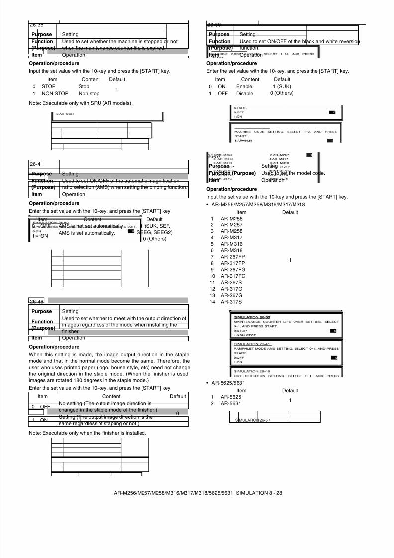
8/9/2019 AR-M318 SM
http://slidepdf.com/reader/full/ar-m318-sm 70/159
AR-M256/M257/M258/M316/M317/M318/5625/5631 SIMULATION 8 - 28
Operation/procedureInput the set value with the 10-key and press the [START] key.
Note: Executable only with SRU (AR models).
Operation/procedureEnter the set value with the 10-key, and press the [START] key.
Operation/procedureWhen this setting is made, the image output direction in the staplemode and that in the normal mode become the same. Therefore, theuser who uses printed paper (logo, house style, etc) need not changethe original direction in the staple mode. (When the finisher is used,images are rotated 180 degrees in the staple mode.)Enter the set value with the 10-key, and press the [START] key.
Note: Executable only when the finisher is installed.
Operation/procedureEnter the set value with the 10-key, and press the [START] key.
Operation/procedure
Input the set value with the 10-key and press the [START] key.• AR-M256/M257/M258/M316/M317/M318
• AR-5625/5631
26-36
Purpose SettingFunction(Purpose)
Used to set whether the machine is stopped or notwhen the maintenance counter life is expired.
Item Operation
Item Content Default0 STOP Stop
11 NON STOP Non stop
26-41
Purpose SettingFunction(Purpose)
Used to set ON/OFF of the automatic magnificationratio selection (AMS) when setting the binding function.
Item Operation
Item Content Default0 OFF AMS is not set automatically. 1 (SUK, SEF,
SEEG, SEEG2)0 (Others)1 ON AMS is set automatically.
26-46
Purpose Setting
Function(Purpose)
Used to set whether to meet with the output direction ofimages regardless of the mode when installing thefinisher.
Item Operation
Item Content Default
0 OFFNo setting (The output image direction ischanged in the staple mode of the finisher.)
01 ON
Setting (The output image direction is thesame regardless of stapling or not.)
26-50
Purpose SettingFunction(Purpose)
Used to set ON/OFF of the black and white reversionfunction.
Item Operation
Item Content Default0 ON Enable 1 (SUK)
0 (Others)1 OFF Disable
26-57
Purpose SettingFunction (Purpose) Used to set the model code.Item Operation
Item Default1 AR-M256
1
2 AR-M2573 AR-M2584 AR-M3175 AR-M3166 AR-M3187 AR-267FP8 AR-317FP9 AR-267FG
10 AR-317FG11 AR-267S12 AR-317G13 AR-267G14 AR-317S
Item Default1 AR-5625
12 AR-5631
SIMULATION 26-57
SIMULATION 26-5 7
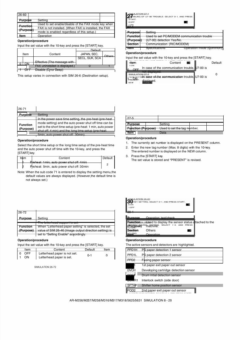
8/9/2019 AR-M318 SM
http://slidepdf.com/reader/full/ar-m318-sm 71/159
AR-M256/M257/M258/M316/M317/M318/5625/5631 SIMULATION 8 - 29
Operation/procedureInput the set value with the 10-key and press the [START] key.
This setup varies in connection with SIM 26-6 (Destination setup).
Operation/procedureSelect the short time setup or the long time setup of the pre-heat timeand the auto power shut off time with the 10-key, and press the[START] key.
Note: When the sub code 71 is entered to display the setting menu,thedefault values are always displayed. (However,the default time isnot always set.)
Operation/procedureInput the set value with the 10-key and press the [START] key.
Operation/procedureInput the set value with the 10-key and press the [START] key.
Operation/procedure1. The currently set number is displayed on the PRESENT column.2. Enter the new tag number (Max. 8 digits) with the 10-key.
The entered number is displayed on the NEW column.3. Press the [START] key.
The set value is stored and “PRESENT” is revised.
Operation/procedureThe active sensors and detectors are highlighted.
26-60
Purpose Setting
Function(Purpose)
Used to set enable/disable of the FAX mode key whenFAX is not installed. (When FAX is installed, the FAXmode is enabled regardless of this setup.)
Item Operation
Item ContentDefault
JAPAN, SEC,
SECL, SUK, SCAOthers
0 ON Effective (The message withFAX uninstalled is displayed.) 0 1
1 OFF Disable (Error Beep)
26-71
Purpose Setting
Function(Purpose)
In the power save time setting, the pre-heat (pre-heatmode setting) and the auto power shut off time can beset to the short time setup (pre-heat: 1 min, auto powershut off: 4 min) and the long time setup (pre-heat:5min, auto power shut off: 30min).
Item Content Default1 Preheat: 1min, auto power shut off: 4min
22 Preheat: 5min, auto power shut off: 30min
26-72
Purpose Setting
Function(Purpose)
The letterhead support is set.When “Letterhead paper setting” is selected, the setvalue of SIM 26-46 (Image output direction setting) isset to “Setting Enable” accordingly.
Item Content Default Item0 OFF Letterhead paper is not set.
0-1 01 ON Letterhead paper is set.
SIMULATION 26-72
27
27-1
Purpose SettingFunction(Purpose)
Used to set PC/MODEM communication trouble(U7-00) detection Yes/No.
Section Communication (RIC/MODEM)Item Specifications Operation mode (Common)
Item Content Default
0 OFFIn case of the communication trouble, U7-00 isnot displayed.
01 ON
In case of the communication trouble, U7-00 isdisplayed.
27-5Purpose SettingFunction (Purpose) Used to set the tag number.Item Data
30
30-1
Purpose Operation test/checkFunction(Purpose)
Used to display the sensor status attached to themachine.
Section OthersItem Operation
PPD1H PS paper detection 1 sensor
PPD1L PS paper detection 2 sensor
PPD2 Fusing paper sensor
POD1 1st paper exit paper out sensor
DVCH Developing cartridge detection sensor
DRST Drum intial detection sensor
DSWR1 Interlock switch (side door)
SFTHP Shifter home position sensor
POD2 2nd paper exit paper out sensor
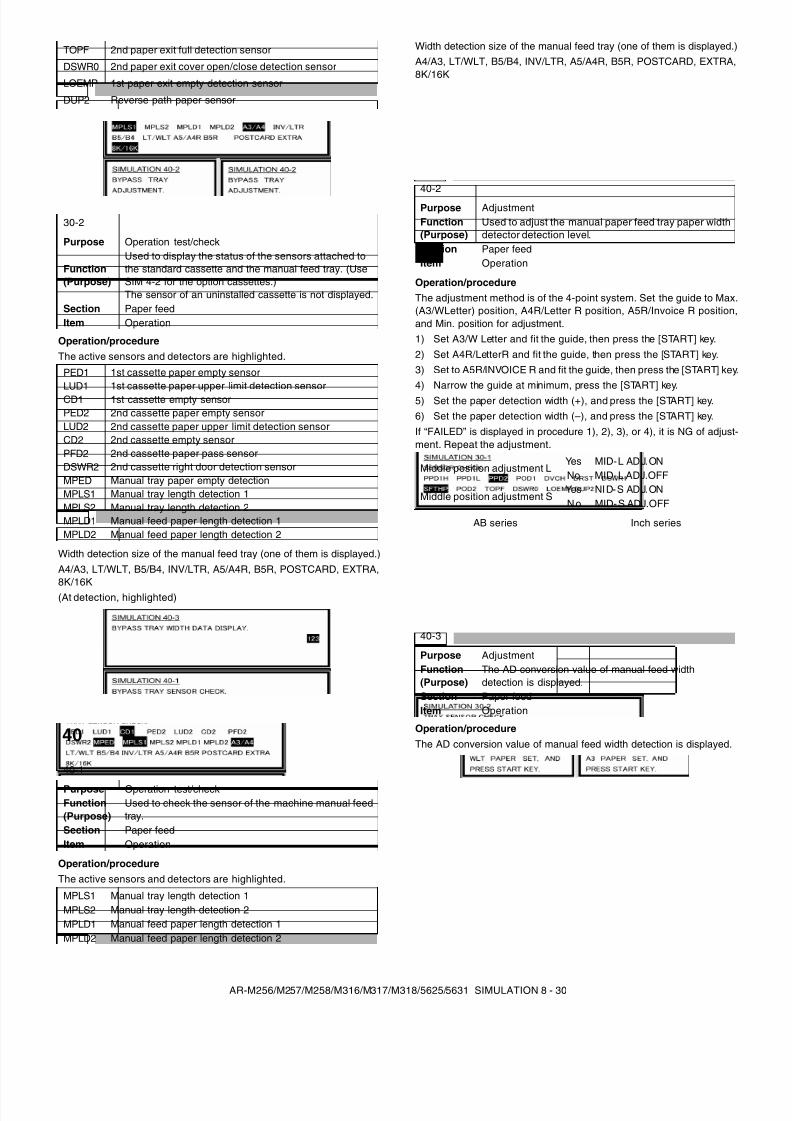
8/9/2019 AR-M318 SM
http://slidepdf.com/reader/full/ar-m318-sm 72/159
AR-M256/M257/M258/M316/M317/M318/5625/5631 SIMULATION 8 - 30
Operation/procedureThe active sensors and detectors are highlighted.
Width detection size of the manual feed tray (one of them is displayed.)A4/A3, LT/WLT, B5/B4, INV/LTR, A5/A4R, B5R, POSTCARD, EXTRA,8K/16K(At detection, highlighted)
Operation/procedureThe active sensors and detectors are highlighted.
Width detection size of the manual feed tray (one of them is displayed.)A4/A3, LT/WLT, B5/B4, INV/LTR, A5/A4R, B5R, POSTCARD, EXTRA,8K/16K
Operation/procedureThe adjustment method is of the 4-point system. Set the guide to Max.(A3/WLetter) position, A4R/Letter R position, A5R/Invoice R position,and Min. position for adjustment.1) Set A3/W Letter and fit the guide, then press the [START] key.2) Set A4R/LetterR and fit the guide, then press the [START] key.3) Set to A5R/INVOICE R and fit the guide, then press the [START] key.4) Narrow the guide at minimum, press the [START] key.5) Set the paper detection width (+), and press the [START] key.6) Set the paper detection width (–), and press the [START] key.If “FAILED” is displayed in procedure 1), 2), 3), or 4), it is NG of adjust-ment. Repeat the adjustment.
Operation/procedureThe AD conversion value of manual feed width detection is displayed.
TOPF 2nd paper exit full detection sensor
DSWR0 2nd paper exit cover open/close detection sensor
LOEMP 1st paper exit empty detection sensor
DUP2 Reverse path paper sensor
30-2
Purpose Operation test/check
Function(Purpose)
Used to display the status of the sensors attached tothe standard cassette and the manual feed tray. (UseSIM 4-2 for the option cassettes.)The sensor of an uninstalled cassette is not displayed.
Section Paper feedItem Operation
PED1 1st cassette paper empty sensorLUD1 1st cassette paper upper limit detection sensorCD1 1st cassette empty sensorPED2 2nd cassette paper empty sensorLUD2 2nd cassette paper upper limit detection sensorCD2 2nd cassette empty sensorPFD2 2nd cassette paper pass sensorDSWR2 2nd cassette right door detection sensorMPED Manual tray paper empty detectionMPLS1 Manual tray length detection 1MPLS2 Manual tray length detection 2MPLD1 Manual feed paper length detection 1MPLD2 Manual feed paper length detection 2
40
40-1
Purpose Operation test/checkFunction(Purpose)
Used to check the sensor of the machine manual feedtray.
Section Paper feedItem Operation
MPLS1 Manual tray length detection 1MPLS2 Manual tray length detection 2MPLD1 Manual feed paper length detection 1MPLD2 Manual feed paper length detection 2
40-2
Purpose AdjustmentFunction(Purpose)
Used to adjust the manual paper feed tray paper widthdetector detection level.
Section Paper feedItem Operation
Middle position adjustment LYes MID-L ADJ.ONNo MID-L ADJ.OFF
Middle position adjustment SYes NID-S ADJ.ONNo MID-S ADJ.OFF
AB series Inch series
40-3
Purpose AdjustmentFunction(Purpose)
The AD conversion value of manual feed widthdetection is displayed.
Section Paper feedItem Operation
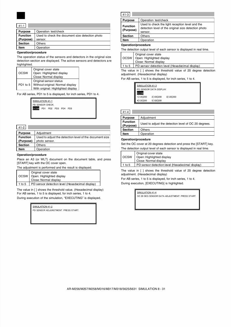
8/9/2019 AR-M318 SM
http://slidepdf.com/reader/full/ar-m318-sm 73/159
AR-M256/M257/M258/M316/M317/M318/5625/5631 SIMULATION 8 - 31
Operation/procedure
The operation status of the sensors and detectors in the original sizedetection section are displayed. The active sensors and detectors a rehighlighted.
For AB series, PD1 to 5 is displayed, for inch series, PD1 to 4.
Operation/procedurePlace an A3 (or WLT) document on the document table, and press[START] key with the OC cover open.The adjustment is performed and the result is displayed.
The value in [ ] shows the threshold value. (Hexadecimal display)For AB series, 1 to 5 is displayed, for inch series, 1 to 4.During execution of the simulation, “EXECUTING” is displayed.
Operation/procedureThe detection output level of each sensor is displayed in real time.
The value in [ ] shows the threshold value of 20 degree detectionadjustment. (Hexadecimal display)For AB series, 1 to 5 is displayed, for inch series, 1 to 4.
Operation/procedureSet the OC cover at 20 degrees detection and press the [START] key.The detection output level of each sensor is displayed in real time.
The value in [ ] shows the threshold value of 20 degree detectionadjustment. (Hexadecimal display)For AB series, 1 to 5 is displayed, for inch series, 1 to 4.During execution, [EXECUTING] is highlighted.
41
41-1
Purpose Operation test/checkFunction(Purpose)
Used to check the document size detection photosensor.
Section OthersItem Operation
OCSWOriginal cover stateOpen: Highlighted displayClose: Normal display
PD1 to 5Original sensor statusWithout original: Normal displayWith original: Highlighted display
41-2
Purpose AdjustmentFunction(Purpose)
Used to adjust the detection level of the document sizephoto sensor.
Section OthersItem Operation
OCSWOriginal cover stateOpen: Highlighted displayClose: Normal display
1 to 5 PD sensor detection level (Hexadecimal display)
41-3
Purpose Operation test/check
Function(Purpose)
Used to check the light reception level and thedetection level of the original size detection photosensor.
Section OthersItem Operation
OCSWOriginal cover stateOpen: Highlighted displayClose: Normal display
1 to 5 PD sensor detection level (Hexadecimal display)
41-4
Purpose AdjustmentFunction(Purpose)
Used to adjust the detection level of OC 20 degrees.
Section OthersItem Operation
OCSWOriginal cover stateOpen: Highlighted displayClose: Normal display
1 to 5 PD sensor detection level (Hexadecimal display)
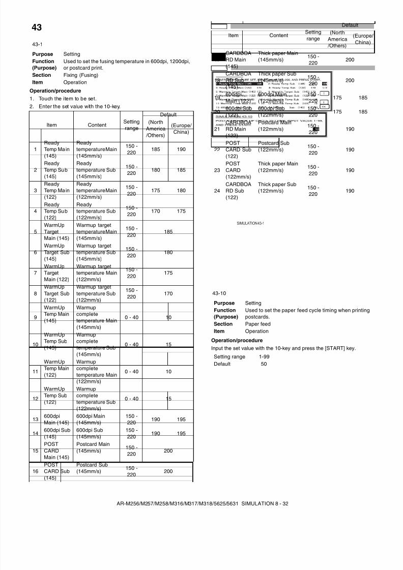
8/9/2019 AR-M318 SM
http://slidepdf.com/reader/full/ar-m318-sm 74/159
AR-M256/M257/M258/M316/M317/M318/5625/5631 SIMULATION 8 - 32
Operation/procedure
1. Touch the item to be set.2. Enter the set value with the 10-key.
Operation/procedureInput the set value with the 10-key and press the [START] key.
43
43-1
Purpose SettingFunction(Purpose)
Used to set the fusing temperature in 600dpi, 1200dpi,or postcard print.
Section Fixing (Fusing)Item Operation
Item ContentSettingrange
Default(North
America /Others)
(Europe/ China)
1ReadyTemp Main(145)
Readytemperature Main(145mm/s)
150 -220
185 190
2ReadyTemp Sub(145)
Readytemperature Sub(145mm/s)
150 -220 180 185
3ReadyTemp Main
(122)
Readytemperature Main
(122mm/s)
150 -220
175 180
4ReadyTemp Sub(122)
Readytemperature Sub(122mm/s)
150 -220 170 175
5WarmUpTargetMain (145)
Warmup targettemperature Main(145mm/s)
150 -220
185
6WarmUpTarget Sub(145)
Warmup targettemperature Sub(145mm/s)
150 -220
180
7WarmUpTargetMain (122)
Warmup targettemperature Main(122mm/s)
150 -220
175
8WarmUpTarget Sub
(122)
Warmup targettemperature Sub
(122mm/s)
150 -220 170
9
WarmUpTemp Main(145)
Warmupcompletetemperature Main(145mm/s)
0 - 40 10
10
WarmUpTemp Sub(145)
Warmupcompletetemperature Sub(145mm/s)
0 - 40 15
11
WarmUpTemp Main(122)
Warmupcompletetemperature Main(122mm/s)
0 - 40 10
12
WarmUpTemp Sub(122)
Warmupcompletetemperature Sub(122mm/s)
0 - 40 15
13600dpiMain (145)
600dpi Main(145mm/s)
150 -220 190 195
14600dpi Sub(145)
600dpi Sub(145mm/s)
150 -220
190 195
15POSTCARDMain (145)
Postcard Main(145mm/s)
150 -220 200
16POSTCARD Sub(145)
Postcard Sub(145mm/s) 150 -
220200
17CARDBOARD Main(145)
Thick paper Main(145mm/s) 150 -
220200
18CARDBOARD Sub(145)
Thick paper Sub(145mm/s)
150 -220 200
19600dpiMain (122)
600dpi Main(122mm/s)
150 -220 175 185
20600dpi Sub(122)
600dpi Sub(122mm/s)
150 -220 175 185
21CARDBOARD Main(122)
Postcard Main(122mm/s)
150 -220 190
22POSTCARD Sub(122)
Postcard Sub(122mm/s)
150 -220
190
23POSTCARD(122mm/s)
Thick paper Main(122mm/s)
150 -220
190
24CARDBOARD Sub
(122)
Thick paper Sub(122mm/s) 150 -
220190
43-10
Purpose SettingFunction(Purpose)
Used to set the paper feed cycle timing when printingpostcards.
Section Paper feedItem Operation
Setting range 1-99Default 50
Item ContentSettingrange
Default(North
America /Others)
(Europe/ China)
SIMULATION 43-1
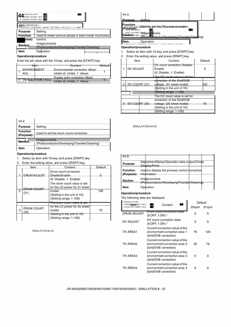
8/9/2019 AR-M318 SM
http://slidepdf.com/reader/full/ar-m318-sm 75/159
AR-M256/M257/M258/M316/M317/M318/5625/5631 SIMULATION 8 - 33
Operation/procedureEnter the set value with the 10-key, and press the [START] key.
Operation/procedure1. Select an item with 10-key, and press [START] key.2. Enter the setting value, and press [START] key.
Operation/procedure1. Select an item with 10-key, and press [START] key.
2. Enter the setting value, and press [START] key.
Operation/procedureThe following data are displayed.
44
44-1
Purpose SettingFunction(Purpose)
Used to make various setups in each mode of processcontrol.
SectionImage process(Photoconductor/Developing/Transfer/Cleaning)
Item Operation
Item Content Default
1ENVIRONMENTADJ.
Environmental correction Allow/Inhibit (0: Inhibit, 1: Allow)
1
2 DUPLEX PRINT ADJ.Duplex print correction Allow/Inhibit (0: Inhibit, 1: Allow) 0
44-2
Purpose Setting
Function(Purpose)
Used to set the drum count correction.
SectionImage process(Photoconductor/Developing/Transfer/Cleaning)
Item Operation
Item Content Default
1 DRUM ADJUSTDrum count correctionDisable/Enable(0: Disable, 1: Enable)
0
2DRUM COUNT(31)
The drum count value is setfor the LD power for 31 sheetmodel.(Setting in the unit of 1K)(Setting range: 1-100)
100
3 DRUM COUNT(25)
The drum count value is setfor the LD power for 25 sheetmodel.(Setting in the unit of 1K)(Setting range: 1-100)
75
SIMULATION 44-02
44-3
Purpose Setting
Function(Purpose)
Used to set the DV count correction.
SectionImage process(Photoconductor/Developing/Transfer/Cleaning)
Item Operation
Item Content Default
1 DV ADJUSTDV count correction Disable/ Enable(0: Disable, 1: Enable)
0
2 DV COUNT (31)
The DV count value is set forcorrection of the Grid/DVBvoltage. (31 sheet model)(Setting in the unit of 1K)(Setting range: 1-100)
100
3 DV COUNT (25)
The DV count value is set forcorrection of the Grid/DVBvoltage. (25 sheet model)(Setting in the unit of 1K)(Setting range: 1-100)
75
44-9
PurposeAdjustment/Setup/Operation data output/Check(Display/Print)
Function(Purpose) Used to display the process control correctioninformation.
SectionImage process(Photoconductor/Developing/Transfer/Cleaning)
Item Operation
Item ContentDefault
25cpm 31cpm
DRUM ADJUSTDrum count correction state(0:OFF, 1:ON) * 0 0
DV ADJUSTDV count correction state(0:OFF, 1:ON) *
0 0
TH AREA1 Current correction value of theenvironment correction area 1(Grid/DVB correction)
76 126
TH AREA2Current correction value of theenvironment correction area 2(Grid/DVB correction)
26 76
TH AREA3Current correction value of theenvironment correction area 3(Grid/DVB correction)
0 0
TH AREA4Current correction value of theenvironment correction area 4(Grid/DVB correction)
0 0
SIMULATION 44-03
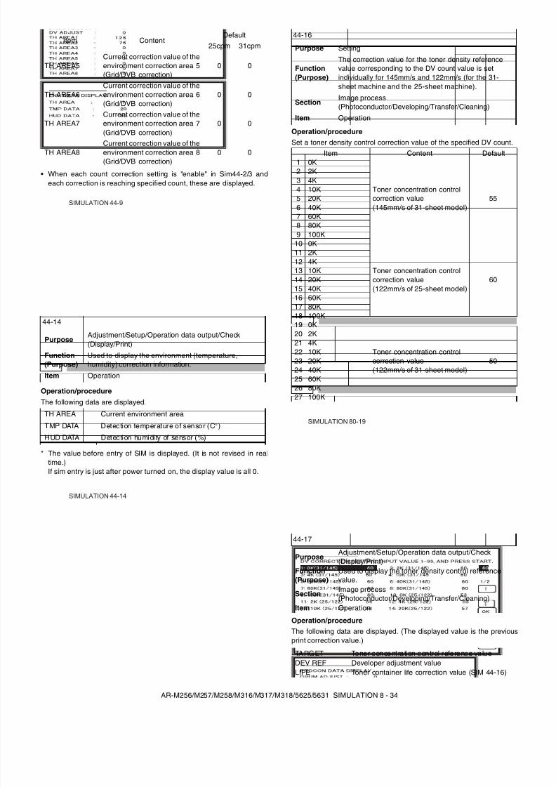
8/9/2019 AR-M318 SM
http://slidepdf.com/reader/full/ar-m318-sm 76/159
AR-M256/M257/M258/M316/M317/M318/5625/5631 SIMULATION 8 - 34
• When each count correction setting is "enable" in Sim44-2/3 andeach correction is reaching specified count, these are displayed.
Operation/procedure
The following data are displayed.
* The value before entry of SIM is displayed. (It is not revised in realtime.)If sim entry is just after power turned on, the display value is all 0.
Operation/procedureSet a toner density control correction value of the specified DV count.
Operation/procedureThe following data are displayed. (The displayed value is the previousprint correction value.)
TH AREA5Current correction value of theenvironment correction area 5(Grid/DVB correction)
0 0
TH AREA6Current correction value of theenvironment correction area 6(Grid/DVB correction)
0 0
TH AREA7Current correction value of theenvironment correction area 7(Grid/DVB correction)
0 0
TH AREA8Current correction value of theenvironment correction area 8(Grid/DVB correction)
0 0
44-14
PurposeAdjustment/Setup/Operation data output/Check(Display/Print)
Function(Purpose)
Used to display the environment (temperature,humidity) correction information.
Item Operation
TH AREA Current environment areaTMP DATA Detection temperature of sensor (C°)
HUD DATA Detection humidity of sensor (%)
Item ContentDefault
25cpm 31cpm
SIMULATION 44-9
SIMULATION 44-14
44-16
Purpose Setting
Function(Purpose)
The correction value for the toner density referencevalue corresponding to the DV count value is setindividually for 145mm/s and 122mm/s (for the 31-sheet machine and the 25-sheet machine).
SectionImage process(Photoconductor/Developing/Transfer/Cleaning)
Item Operation
Item Content Default1 0K
Toner concentration controlcorrection value(145mm/s of 31-sheet model)
55
2 2K3 4K4 10K5 20K6 40K7 60K8 80K9 100K
10 0K
Toner concentration controlcorrection value(122mm/s of 25-sheet model)
60
11 2K12 4K13 10K14 20K15 40K16 60K17 80K18 100K19 0K
Toner concentration controlcorrection value(122mm/s of 31-sheet model)
50
20 2K21 4K22 10K23 20K24 40K25 60K26 80K27 100K
44-17
Purpose Adjustment/Setup/Operation data output/Check(Display/Print)
Function(Purpose)
Used to display the toner density control referencevalue.
SectionImage process(Photoconductor/Developing/Transfer/Cleaning)
Item Operation
TARGET Toner concentration control reference valueDEV REF Developer adjustment valueLIFE Toner container life correction value (SIM 44-16)
SIMULATION 80-19
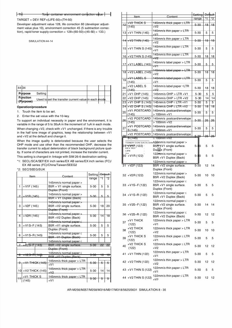
8/9/2019 AR-M318 SM
http://slidepdf.com/reader/full/ar-m318-sm 77/159
AR-M256/M257/M258/M316/M317/M318/5625/5631 SIMULATION 8 - 35
TARGET = DEV REF+(LIFE-50)+(TH-50)Developer adjustment value 128, life correction 60 (developer adjust-ment value plus 10), environment correction 45 (5 subtraction correc-tion), rapid toner supply correction = 128+(60-50)+(45-50) = 133.)
Operation/procedure1. Touch the item to be set.2. Enter the set value with the 10-key.To support an individual necessity in paper and the environment, it isvariable in the range of 5 to 30uA in the increment of 1uA in each mode.When changing +V2, check with +V1 unchanged. If there is any troublein the half tone image of graphics, keep the relationship between +V1and +V2 at the default and change it.When the image quality is deteriorated because the user selects theOHP mode and use other than the recommended OHP, decrease thetransfer current to adjust deterioration of black background picture qual-ity. If some of characters are not printed, increase the transfer current.This setting is changed in linkage with SIM 26-6 destination setting.*1: SECL/SCA/SEF/EX inch series/EX AB series/EX inch series (FC)/
EX AB series (FC)/China/Taiwan/SEEG2*2: SEC/SEEG/SUK
TH Toner container environment correction value
44-34
Purpose SettingFunction(Purpose)
Used to set the transfer current value in each mode.
Item Content Settingrange
Default*1 *2
1 +V1F (145)145mm/s normal paper >B5R + V1 single surface.Duplex (Front)
5-30 5 5
2 +V1R (145)145mm/s normal paper >B5R + V1 Duplex (Back) 5-30 5 5
3 +V2F (145)145mm/s normal paper >B5R +V2 single surface.Duplex (Front)
5-30 18 20
4 +V2R (145)145mm/s normal paper >B5R +V2 Duplex (Back)
5-30 14 18
5 +V1S–F (145)145mm/s normal paper ≤ B5R +V1 single surface.
Duplex (Front)
5-30 5 5
6 +V1S–R (145) 145mm/s normal paper ≤ B5R +V1 Duplex (Back)
5-30 5 5
7 +V2S–F (145)145mm/s normal paper ≤ B5R +V2 single surface.Duplex (Front)
5-30 22 22
8 +V2S–R (145)145mm/s normal paper ≤ B5R +V2 Duplex (Back)
5-30 18 18
9 +V1 THICK (145)145mm/s thick paper > LTR+V1 5-30 5 5
10 +V2 THICK (145)145mm/s thick paper > LTR+V2
5-30 14 14
11+V1 THICK S(145)
145mm/s thick paper ≤ LTR+V1
5-30 5 5
SIMULATION 44-14
12+V2 THICK S(145)
145mm/s thick paper ≤ LTR+V2 5-30 18 18
13 +V1 THIN (145)145mm/s thin paper > LTR+V1 5-30 5 5
14 +V2 THIN (145)145mm/s thin paper > LTR+V2
5-30 18 18
15 +V1 THIN S (145)145mm/s thin paper ≤ LTR+V1 5-30 5 5
16 +V2 THIN S (145)145mm/s thin paper ≤ LTR+V2 5-30 18 18
17 +V1 LABEL (145)145mm/s label paper > LTR+V1 5-30 5 5
18 +V2 LABEL (145)145mm/s label paper > LTR+V2
5-30 18 18
19+V1 LABEL S(145)
145mm/s label paper ≤ LTR+V1
5-30 5 5
20+V2 LABEL S(145)
145mm/s label paper ≤LTR+V2
5-30 18 18
21 +V1 OHP (145) 145mm/s OHP > LTR +V1 5-30 5 522 +V2 OHP (145) 145mm/s OHP > LTR +V2 5-30 14 1423 +V1 OHP S (145) 145mm/s OHP ≤ LTR +V1 5-30 5 524 +V2 OHP S (145) 145mm/s OHP ≤ LTR +V2 5-30 18 18
25+V1 POSTCARD
(145)
145mm/s postcard/envelope
> 100mm +V15-30 5 5
26+V2 POSTCARD(145)
145mm/s postcard/envelope> 100mm +V2 5-30 26 26
27+V1 POSTCARDS (145)
145mm/s postcard/envelope≤ 100mm +V1 5-30 5 5
28+V2 POSTCARDS (145)
145mm/s postcard/envelope≤ 100mm +V2
5-30 26 26
29 +V1F (122)122mm/s normal paper >B5R +V1 single surface.Duplex (Front)
5-30 5 5
30 +V1R (122)122mm/s normal paper >B5R +V1 Duplex (Back)
5-30 5 5
31 +V2F (122)122mm/s normal paper >B5R +V2 single surface.Duplex (Front)
5-30 12 14
32 +V2R (122) 122mm/s normal paper >B5R +V2 Duplex (Back)
5-30 10 10
33 +V1S–F (122)122mm/s normal paper ≤ B5R +V1 single surface.Duplex (Front)
5-30 5 5
34 +V1S–R (122)122mm/s normal paper ≤ B5R +V1 Duplex (Back) 5-30 5 5
35 +V2S–F (122)122mm/s normal paper ≤ B5R +V2 single surface.Duplex (Front)
5-30 14 14
36 +V2S–R (122)122mm/s normal paper ≤ B5R +V2 Duplex (Back)
5-30 12 12
37+V1 THICK (122)
122mm/s thick paper > LTR+V1
5-30 5 5
38 +V2 THICK (122) 122mm/s thick paper > LTR+V2 5-30 10 10
39+V1 THICK S(122)
122mm/s thick paper ≤ LTR+V1
5-30 5 5
40+V2 THICK S (122)
122mm/s thick paper ≤ LTR+V2
5-30 12 12
41 +V1 THIN (122)122mm/s thin paper > LTR+V1
5-30 5 5
42 +V2 THIN (122)122mm/s thin paper > LTR+V2
5-30 12 12
43 +V1 THIN S (122)122mm/s thin paper ≤ LTR+V1
5-30 5 5
44 +V2 THIN S (122)122mm/s thin paper ≤ LTR+V2
5-30 12 12
Item ContentSettingrange
Default*1 *2
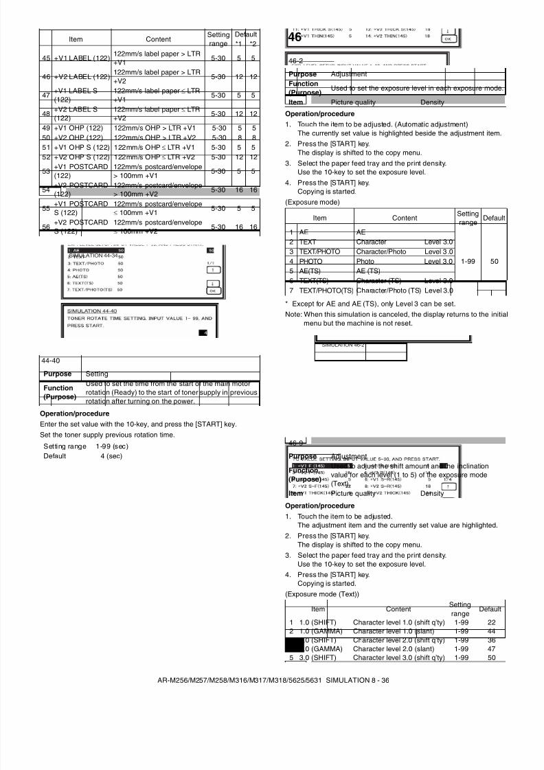
8/9/2019 AR-M318 SM
http://slidepdf.com/reader/full/ar-m318-sm 78/159
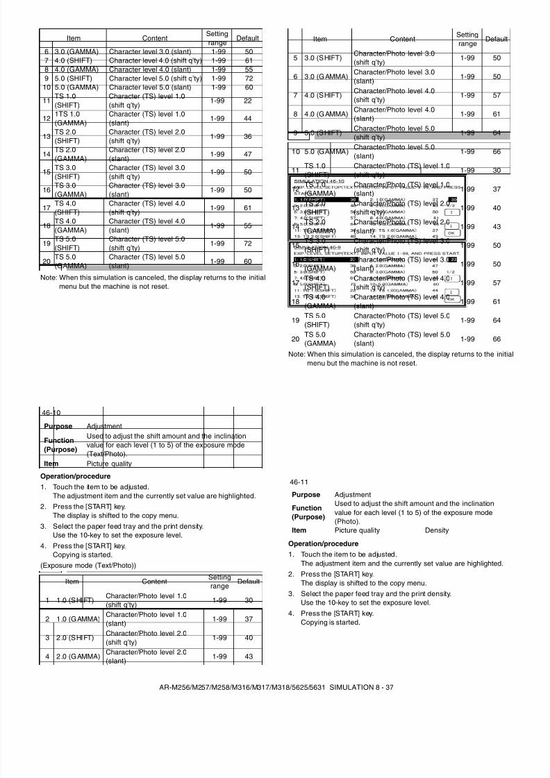
8/9/2019 AR-M318 SM
http://slidepdf.com/reader/full/ar-m318-sm 79/159
AR-M256/M257/M258/M316/M317/M318/5625/5631 SIMULATION 8 - 37
Note: When this simulation is canceled, the display returns to the initialmenu but the machine is not reset.
Operation/procedure1. Touch the item to be adjusted.
The adjustment item and the currently set value are highlighted.2. Press the [START] key.
The display is shifted to the copy menu.3. Select the paper feed tray and the print density.
Use the 10-key to set the exposure level.
4. Press the [START] key.Copying is started.
(Exposure mode (Text/Photo))
Note: When this simulation is canceled, the display returns to the initialmenu but the machine is not reset.
Operation/procedure1. Touch the item to be adjusted.
The adjustment item and the currently set value are highlighted.2. Press the [START] key.
The display is shifted to the copy menu.3. Select the paper feed tray and the print density.
Use the 10-key to set the exposure level.4. Press the [START] key.
Copying is started.
6 3.0 (GAMMA) Character level 3.0 (slant) 1-99 507 4.0 (SHIFT) Character level 4.0 (shift q’ty) 1-99 618 4.0 (GAMMA) Character level 4.0 (slant) 1-99 559 5.0 (SHIFT) Character level 5.0 (shift q’ty) 1-99 72
10 5.0 (GAMMA) Character level 5.0 (slant) 1-99 60
11TS 1.0(SHIFT)
Character (TS) level 1.0(shift q’ty)
1-99 22
121TS 1.0(GAMMA)
Character (TS) level 1.0(slant)
1-99 44
13TS 2.0(SHIFT)
Character (TS) level 2.0(shift q’ty) 1-99 36
14TS 2.0(GAMMA)
Character (TS) level 2.0(slant)
1-99 47
15 TS 3.0(SHIFT)
Character (TS) level 3.0(shift q’ty)
1-99 50
16TS 3.0(GAMMA)
Character (TS) level 3.0(slant)
1-99 50
17TS 4.0(SHIFT)
Character (TS) level 4.0(shift q’ty) 1-99 61
18TS 4.0(GAMMA)
Character (TS) level 4.0(slant)
1-99 55
19TS 5.0(SHIFT)
Character (TS) level 5.0(shift q’ty)
1-99 72
20TS 5.0(GAMMA)
Character (TS) level 5.0(slant) 1-99 60
46-10
Purpose Adjustment
Function(Purpose)
Used to adjust the shift amount and the inclinationvalue for each level (1 to 5) of the exposure mode(Text/Photo).
Item Picture quality
Item Content Settingrange
Default
1 1 .0 (SHIFT) Character/Photo level 1.0(shift q’ty)
1-99 30
2 1 .0 (GAMMA)Character/Photo level 1.0(slant)
1-99 37
3 2 .0 (SHIFT) Character/Photo level 2.0(shift q’ty)
1-99 40
4 2 .0 (GAMMA) Character/Photo level 2.0(slant)
1-99 43
Item ContentSettingrange
Default
5 3 .0 (SHIFT) Character/Photo level 3.0(shift q’ty)
1-99 50
6 3 .0 (GAMMA)Character/Photo level 3.0(slant)
1-99 50
7 4 .0 (SHIFT) Character/Photo level 4.0(shift q’ty)
1-99 57
8 4 .0 (GAMMA) Character/Photo level 4.0(slant)
1-99 61
9 5 .0 (SHIFT)Character/Photo level 5.0(shift q’ty) 1-99 64
10 5.0 (GAMMA)Character/Photo level 5.0(slant)
1-99 66
11TS 1.0(SHIFT)
Character/Photo (TS) level 1.0(shift q’ty)
1-99 30
12TS 1.0(GAMMA)
Character/Photo (TS) level 1.0(slant) 1-99 37
13TS 2.0(SHIFT)
Character/Photo (TS) level 2.0(shift q’ty) 1-99 40
14TS 2.0(GAMMA)
Character/Photo (TS) level 2.0(slant) 1-99 43
15TS 3.0(SHIFT)
Character/Photo (TS) level 3.0(shift q’ty)
1-99 50
16TS 3.0(GAMMA)
Character/Photo (TS) level 3.0(slant) 1-99 50
17TS 4.0(SHIFT)
Character/Photo (TS) level 4.0(shift q’ty) 1-99 57
18TS 4.0(GAMMA)
Character/Photo (TS) level 4.0(slant) 1-99 61
19TS 5.0(SHIFT)
Character/Photo (TS) level 5.0(shift q’ty)
1-99 64
20TS 5.0(GAMMA)
Character/Photo (TS) level 5.0(slant) 1-99 66
46-11
Purpose Adjustment
Function(Purpose)
Used to adjust the shift amount and the inclinationvalue for each level (1 to 5) of the exposure mode(Photo).
Item Picture quality Density
Item Content Settingrange
Default
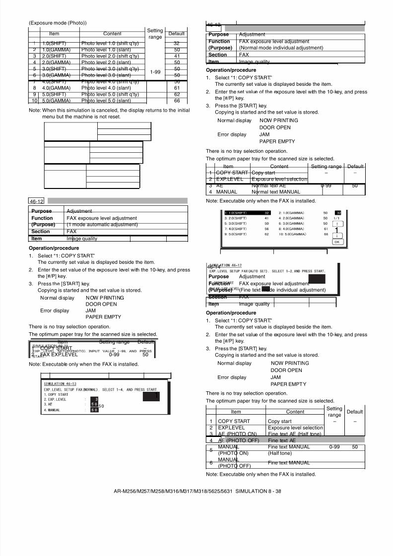
8/9/2019 AR-M318 SM
http://slidepdf.com/reader/full/ar-m318-sm 80/159
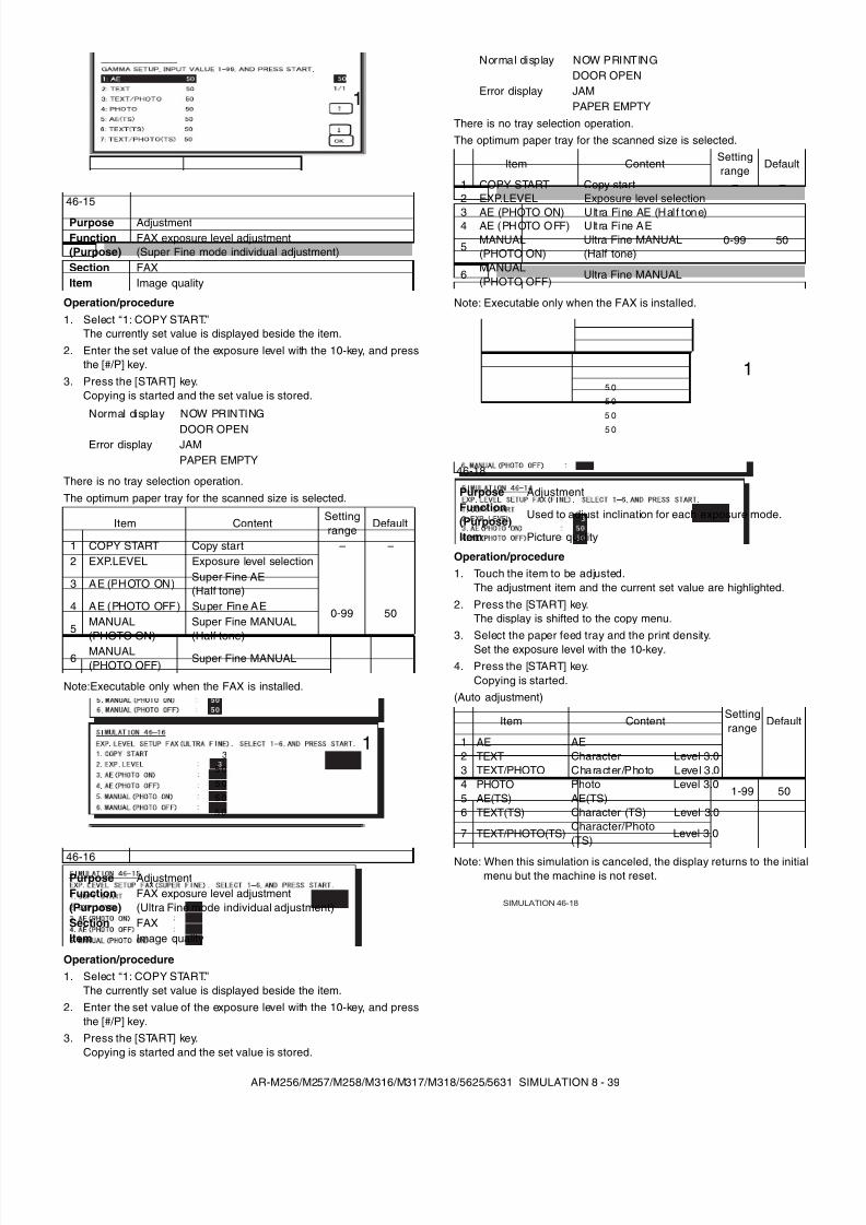
8/9/2019 AR-M318 SM
http://slidepdf.com/reader/full/ar-m318-sm 81/159
AR-M256/M257/M258/M316/M317/M318/5625/5631 SIMULATION 8 - 39
Operation/procedure1. Select “1: COPY START.”
The currently set value is displayed beside the item.2. Enter the set value of the exposure level with the 10-key, and press
the [#/P] key.3. Press the [START] key.
Copying is started and the set value is stored.
There is no tray selection operation.The optimum paper tray for the scanned size is selected.
Note:Executable only when the FAX is installed.
Operation/procedure1. Select “1: COPY START.”
The currently set value is displayed beside the item.2. Enter the set value of the exposure level with the 10-key, and press
the [#/P] key.3. Press the [START] key.
Copying is started and the set value is stored.
There is no tray selection operation.The optimum paper tray for the scanned size is selected.
Note: Executable only when the FAX is installed.
Operation/procedure1. Touch the item to be adjusted.
The adjustment item and the current set value are highlighted.2. Press the [START] key.
The display is shifted to the copy menu.3. Select the paper feed tray and the print density.
Set the exposure level with the 10-key.4. Press the [START] key.
Copying is started.(Auto adjustment)
Note: When this simulation is canceled, the display returns to the initialmenu but the machine is not reset.
46-15
Purpose AdjustmentFunction(Purpose)
FAX exposure level adjustment(Super Fine mode individual adjustment)
Section FAXItem Image quality
Normal display NOW PRINTING
Error displayDOOR OPENJAMPAPER EMPTY
Item ContentSettingrange
Default
1 COPY START Copy start – –2 EXP.LEVEL Exposure level selection
0-99 50
3 AE (PHOTO ON) Super Fine AE(Half tone)
4 AE (PHOTO OFF) Super Fine AE
5MANUAL(PHOTO ON)
Super Fine MANUAL(Half tone)
6MANUAL(PHOTO OFF)
Super Fine MANUAL
46-16Purpose AdjustmentFunction(Purpose)
FAX exposure level adjustment(Ultra Fine mode individual adjustment)
Section FAXItem Image quality
1
3
5 0
5 0
5 0
5 0
1
Normal display NOW PRINTING
Error displayDOOR OPENJAMPAPER EMPTY
Item ContentSettingrange
Default
1 COPY START Copy start – –2 EXP.LEVEL Exposure level selection
0-99 50
3 AE (PHOTO ON) Ult ra Fine AE (Hal f tone)4 AE (PHOTO OFF) Ult ra Fine AE
5MANUAL(PHOTO ON)
Ultra Fine MANUAL(Half tone)
6MANUAL(PHOTO OFF)
Ultra Fine MANUAL
46-18
Purpose AdjustmentFunction(Purpose)
Used to adjust inclination for each exposure mode.
Item Picture quality
Item ContentSettingrange
Default
1 AE AE
1-99 50
2 TEXT Character Level 3.03 TEXT/PHOTO Character/Photo Level 3.04 PHOTO Photo Level 3.05 AE(TS) AE(TS)6 TEXT(TS) Character (TS) Level 3.0
7 TEXT/PHOTO(TS)Character/Photo(TS)
Level 3.0
5 0
5 0
5 0
5 0
1
SIMULATION 46-18
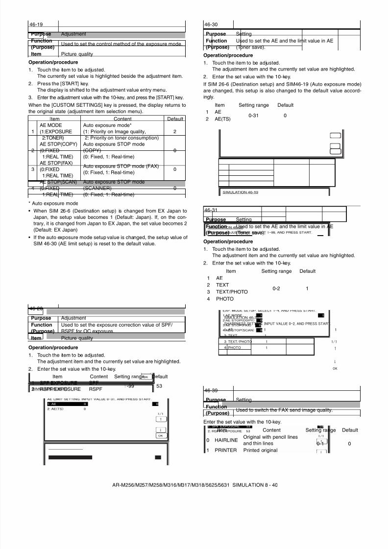
8/9/2019 AR-M318 SM
http://slidepdf.com/reader/full/ar-m318-sm 82/159
AR-M256/M257/M258/M316/M317/M318/5625/5631 SIMULATION 8 - 40
Operation/procedure1. Touch the item to be adjusted.
The currently set value is highlighted beside the adjustment item.2. Press the [START] key.
The display is shifted to the adjustment value entry menu.
3. Enter the adjustment value with the 10-key, and press the [START] key.When the [CUSTOM SETTINGS] key is pressed, the display returns tothe original state (adjustment item selection menu).
* Auto exposure mode• When SIM 26-6 (Destination setup) is changed from EX Japan to
Japan, the setup value becomes 1 (Default: Japan). If, on the con-trary, it is changed from Japan to EX Japan, the set value becomes 2(Default: EX Japan)
• If the auto exposure mode setup value is changed, the setup value ofSIM 46-30 (AE limit setup) is reset to the default value.
Operation/procedure1. Touch the item to be adjusted.
The adjustment item and the currently set value are highlighted.2. Enter the set value with the 10-key.
Operation/procedure1. Touch the item to be adjusted.
The adjustment item and the currently set value are highlighted.2. Enter the set value with the 10-key.If SIM 26-6 (Destination setup) and SIM46-19 (Auto exposure mode)are changed, this setup is also changed to the default value accord-ingly.
Operation/procedure1. Touch the item to be adjusted.
The adjustment item and the currently set value are highlighted.2. Enter the set value with the 10-key.
Enter the set value with the 10-key.
46-19
Purpose AdjustmentFunction(Purpose)
Used to set the control method of the exposure mode.
Item Picture quality
Item Content Default
1AE MODE(1:EXPOSURE
2:TONER)
Auto exposure mode*(1: Priority on Image quality,2: Priority on toner consumption)
2
2AE STOP(COPY)(0:FIXED
1:REAL TIME)
Auto exposure STOP mode(COPY)(0: Fixed, 1: Real-time)
0
3AE STOP(FAX)(0:FIXED
1:REAL TIME)
Auto exposure STOP mode (FAX)(0: Fixed, 1: Real-time) 0
4AE STOP(SCAN)(0:FIXED
1:REAL TIME)
Auto exposure STOP mode(SCANNER)(0: Fixed, 1: Real-time)
0
46-20
Purpose AdjustmentFunction(Purpose)
Used to set the exposure correction value of SPF/ RSPF for OC exposure.
Item Picture quality
Item Content Setting range Default
1 SPF EXPOSURE SPF 1-99 532 RSPF EXPOSURE RSPF
46-30
Purpose SettingFunction(Purpose)
Used to set the AE and the limit value in AE(Toner save).
Item Setting range Default1 AE
0-31 02 AE(TS)
46-31
Purpose SettingFunction(Purpose)
Used to set the AE and the limit value in AE(Toner save).
Item Setting range Default1 AE
0-2 12 TEXT3 TEXT/PHOTO4 PHOTO
46-39
Purpose SettingFunction(Purpose)
Used to switch the FAX send image quality.
Item Content Setting range Default
0 HAIRLINEOriginal with pencil linesand thin lines 0-1 0
1 PRINTER Printed original
SIMULATION 46-31
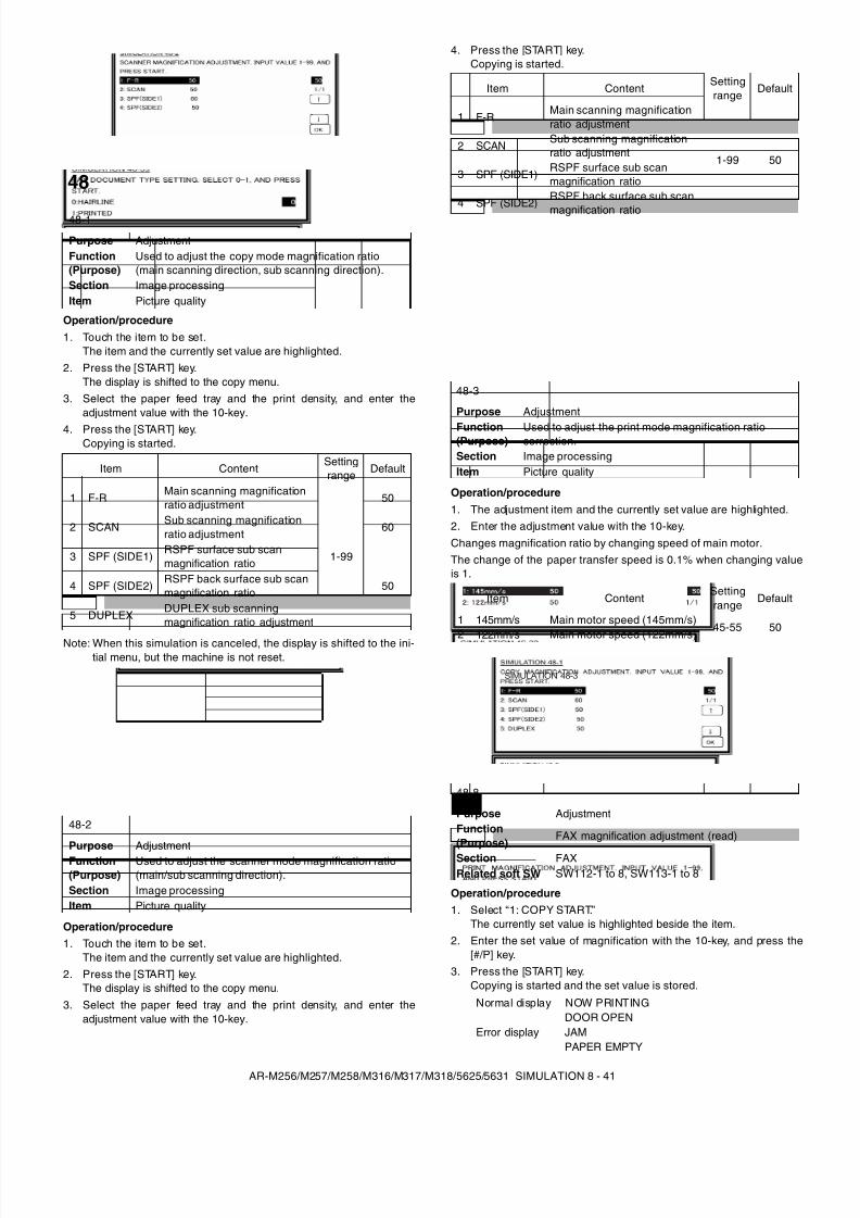
8/9/2019 AR-M318 SM
http://slidepdf.com/reader/full/ar-m318-sm 83/159
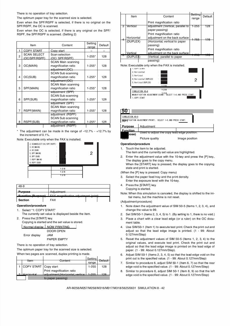
8/9/2019 AR-M318 SM
http://slidepdf.com/reader/full/ar-m318-sm 84/159
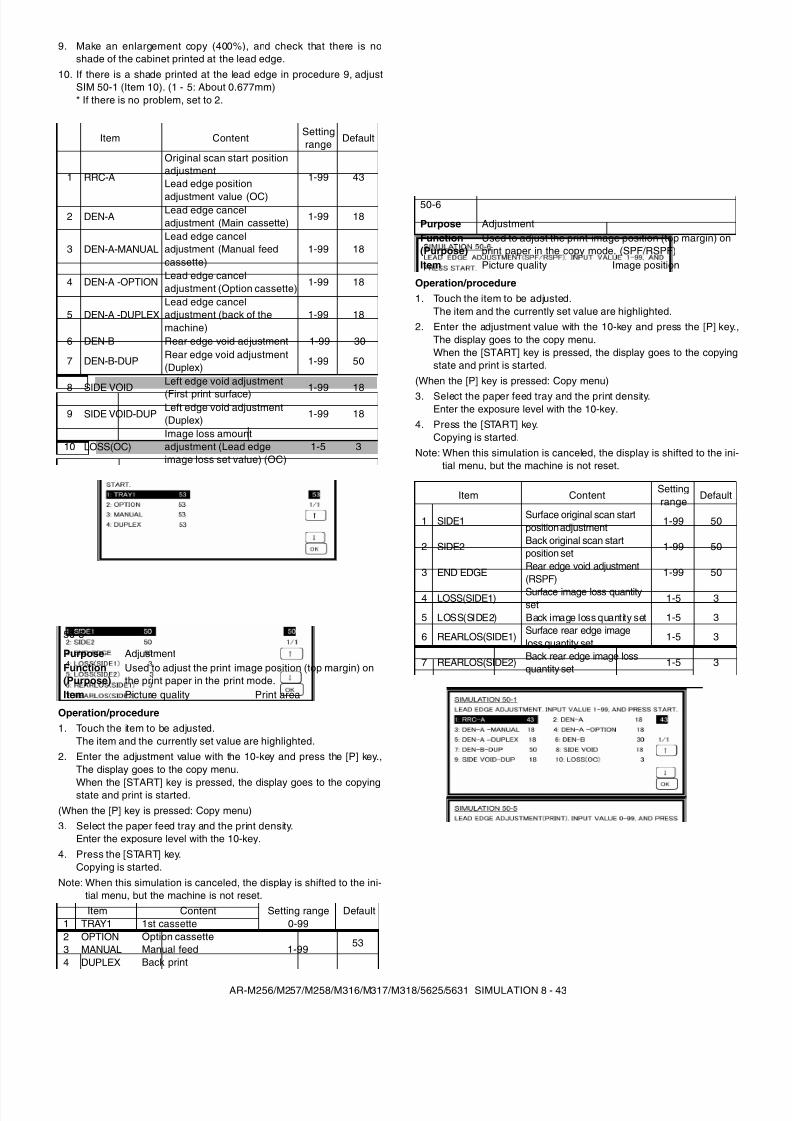
8/9/2019 AR-M318 SM
http://slidepdf.com/reader/full/ar-m318-sm 85/159
AR-M256/M257/M258/M316/M317/M318/5625/5631 SIMULATION 8 - 43
9. Make an enlargement copy (400%), and check that there is noshade of the cabinet printed at the lead edge.
10. If there is a shade printed at the lead edge in procedure 9, adjustSIM 50-1 (Item 10). (1 - 5: About 0.677mm)* If there is no problem, set to 2.
Operation/procedure1. Touch the item to be adjusted.
The item and the currently set value are highlighted.2. Enter the adjustment value with the 10-key and press the [P] key.,
The display goes to the copy menu.
When the [START] key is pressed, the display goes to the copyingstate and print is started.(When the [P] key is pressed: Copy menu)3. Select the paper feed tray and the print density.
Enter the exposure level with the 10-key.4. Press the [START] key.
Copying is started.Note: When this simulation is canceled, the display is shifted to the ini-
tial menu, but the machine is not reset.
Operation/procedure1. Touch the item to be adjusted.
The item and the currently set value are highlighted.2. Enter the adjustment value with the 10-key and press the [P] key.,
The display goes to the copy menu.When the [START] key is pressed, the display goes to the copyingstate and print is started.
(When the [P] key is pressed: Copy menu)
3. Select the paper feed tray and the print density.Enter the exposure level with the 10-key.
4. Press the [START] key.Copying is started.
Note: When this simulation is canceled, the display is shifted to the ini-tial menu, but the machine is not reset.
Item ContentSettingrange Default
1 RRC-A
Original scan start positionadjustmentLead edge position
adjustment value (OC)
1-99 43
2 DEN-ALead edge canceladjustment (Main cassette)
1-99 18
3 DEN-A-MANUALLead edge canceladjustment (Manual feedcassette)
1-99 18
4 DEN-A -OPTIONLead edge canceladjustment (Option cassette)
1-99 18
5 DEN-A -DUPLEXLead edge canceladjustment (back of themachine)
1-99 18
6 DEN-B Rear edge void adjustment 1-99 30
7 DEN-B-DUPRear edge void adjustment(Duplex)
1-99 50
8 SIDE VOIDLeft edge void adjustment(First print surface) 1-99 18
9 SIDE VOID-DUPLeft edge void adjustment(Duplex)
1-99 18
10 LOSS(OC)Image loss amountadjustment (Lead edgeimage loss set value) (OC)
1-5 3
50-5
Purpose AdjustmentFunction(Purpose)
Used to adjust the print image position (top margin) onthe print paper in the print mode.
Item Picture quality Print area
Item Content Setting range Default1 TRAY1 1st cassette 0-99
532 OPTION Option cassette1-993 MANUAL Manual feed
4 DUPLEX Back print
50-6
Purpose AdjustmentFunction(Purpose)
Used to adjust the print image position (top margin) onprint paper in the copy mode. (SPF/RSPF)
Item Picture quality Image position
Item ContentSettingrange
Default
1 SIDE1Surface original scan startposition adjustment
1-99 50
2 SIDE2 Back original scan startposition set
1-99 50
3 END EDGERear edge void adjustment(RSPF)
1-99 50
4 LOSS(SIDE1) Surface image loss quantityset
1-5 3
5 LOSS(SIDE2) Back image loss quantity set 1-5 3
6 REARLOS(SIDE1)Surface rear edge imageloss quantity set
1-5 3
7 REARLOS(SIDE2) Back rear edge image lossquantity set
1-5 3
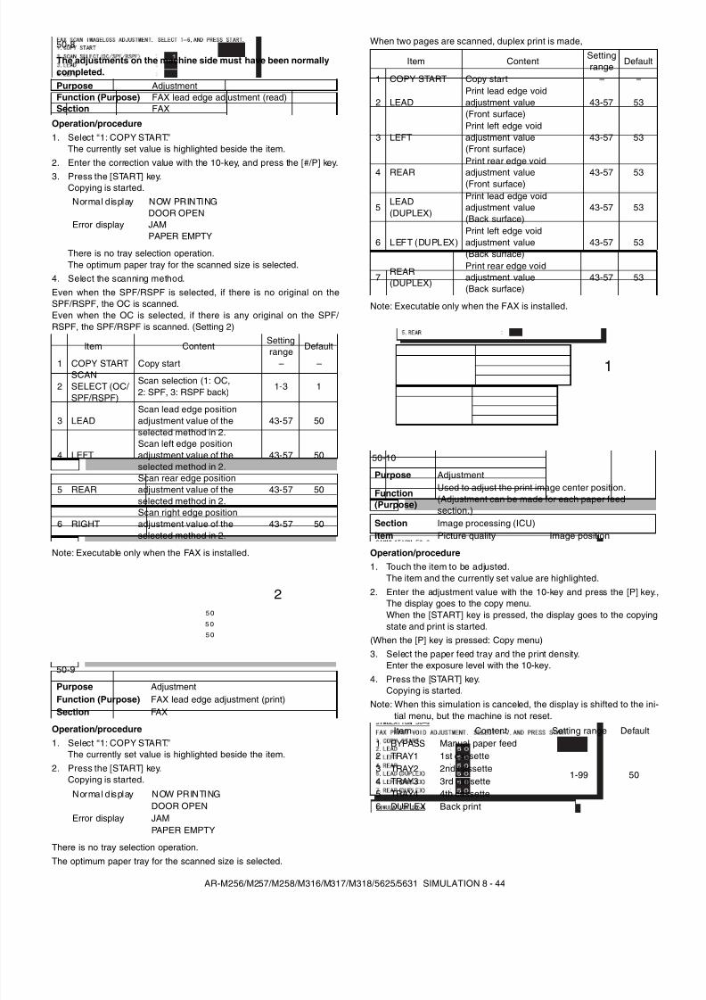
8/9/2019 AR-M318 SM
http://slidepdf.com/reader/full/ar-m318-sm 86/159
AR-M256/M257/M258/M316/M317/M318/5625/5631 SIMULATION 8 - 44
Operation/procedure1. Select “1: COPY START.”
The currently set value is highlighted beside the item.2. Enter the correction value with the 10-key, and press the [#/P] key.
3. Press the [START] key.Copying is started.
There is no tray selection operation.The optimum paper tray for the scanned size is selected.
4. Select the scanning method.Even when the SPF/RSPF is selected, if there is no original on theSPF/RSPF, the OC is scanned.Even when the OC is selected, if there is any original on the SPF/ RSPF, the SPF/RSPF is scanned. (Setting 2)
Note: Executable only when the FAX is installed.
Operation/procedure1. Select “1: COPY START.”
The currently set value is highlighted beside the item.2. Press the [START] key.
Copying is started.
There is no tray selection operation.The optimum paper tray for the scanned size is selected.
When two pages are scanned, duplex print is made,
Note: Executable only when the FAX is installed.
Operation/procedure1. Touch the item to be adjusted.
The item and the currently set value are highlighted.2. Enter the adjustment value with the 10-key and press the [P] key.,
The display goes to the copy menu.When the [START] key is pressed, the display goes to the copyingstate and print is started.
(When the [P] key is pressed: Copy menu)3. Select the paper feed tray and the print density.
Enter the exposure level with the 10-key.4. Press the [START] key.
Copying is started.Note: When this simulation is canceled, the display is shifted to the ini-
tial menu, but the machine is not reset.
50-8
The adjustments on the machine side must have been normallycompleted.Purpose AdjustmentFunction (Purpose) FAX lead edge adjustment (read)Section FAX
Normal display NOW PRINTING
Error displayDOOR OPENJAMPAPER EMPTY
Item ContentSettingrange Default
1 COPY START Copy start – –
2SCANSELECT (OC/ SPF/RSPF)
Scan selection (1: OC,2: SPF, 3: RSPF back)
1-3 1
3 LEADScan lead edge positionadjustment value of theselected method in 2.
43-57 50
4 LEFTScan left edge positionadjustment value of theselected method in 2.
43-57 50
5 REARScan rear edge positionadjustment value of theselected method in 2.
43-57 50
6 RIGHT
Scan right edge position
adjustment value of theselected method in 2.
43-57 50
50-9
Purpose Adjustment
Function (Purpose) FAX lead edge adjustment (print)Section FAX
Normal d isplay NOW PRINTING
Error displayDOOR OPENJAMPAPER EMPTY
5 0
5 0
5 0
2
Item ContentSettingrange Default
1 COPY START Copy start – –
2 LEADPrint lead edge voidadjustment value(Front surface)
43-57 53
3 LEFTPrint left edge voidadjustment value(Front surface)
43-57 53
4 REAR
Print rear edge void
adjustment value(Front surface) 43-57 53
5LEAD(DUPLEX)
Print lead edge voidadjustment value(Back surface)
43-57 53
6 LEFT (DUPLEX)Print left edge voidadjustment value(Back surface)
43-57 53
7REAR(DUPLEX)
Print rear edge voidadjustment value(Back surface)
43-57 53
50-10
Purpose Adjustment
Function(Purpose)
Used to adjust the print image center position.(Adjustment can be made for each paper feedsection.)
Section Image processing (ICU)Item Picture quality Image position
Item Content Setting range Default1 BYPASS Manual paper feed
1-99 50
2 TRAY1 1st cassette3 TRAY2 2nd cassette4 TRAY3 3rd cassette5 TRAY4 4th cassette6 DUPLEX Back print
1
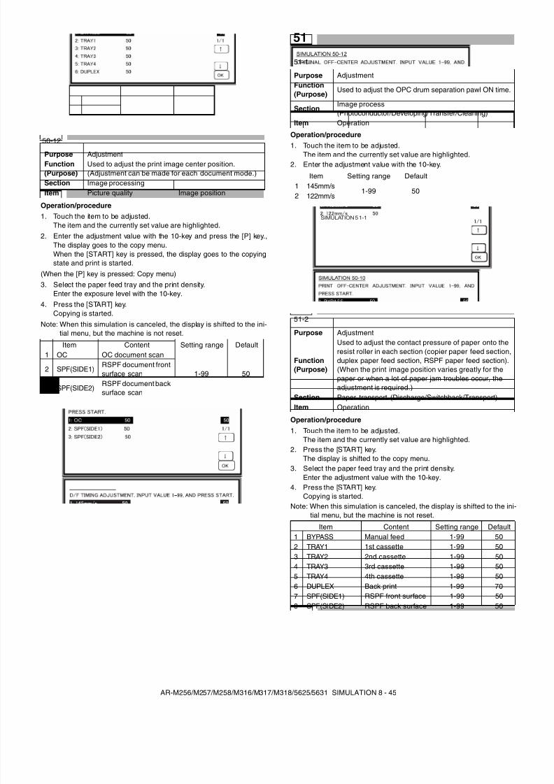
8/9/2019 AR-M318 SM
http://slidepdf.com/reader/full/ar-m318-sm 87/159
AR-M256/M257/M258/M316/M317/M318/5625/5631 SIMULATION 8 - 45
Operation/procedure1. Touch the item to be adjusted.
The item and the currently set value are highlighted.2. Enter the adjustment value with the 10-key and press the [P] key.,
The display goes to the copy menu.When the [START] key is pressed, the display goes to the copyingstate and print is started.
(When the [P] key is pressed: Copy menu)3. Select the paper feed tray and the print density.
Enter the exposure level with the 10-key.4. Press the [START] key.
Copying is started.Note: When this simulation is canceled, the display is shifted to the ini-
tial menu, but the machine is not reset.
Operation/procedure1. Touch the item to be adjusted.
The item and the currently set value are highlighted.2. Enter the adjustment value with the 10-key.
Operation/procedure1. Touch the item to be adjusted.
The item and the currently set value are highlighted.2. Press the [START] key.
The display is shifted to the copy menu.3. Select the paper feed tray and the print density.
Enter the adjustment value with the 10-key.4. Press the [START] key.
Copying is started.Note: When this simulation is canceled, the display is shifted to the ini-
tial menu, but the machine is not reset.
50-12
Purpose AdjustmentFunction(Purpose)
Used to adjust the print image center position.(Adjustment can be made for each document mode.)
Section Image processingItem Picture quality Image position
Item Content Setting range Default1 OC OC document scan
1-99 502 SPF(SIDE1)
RSPF document frontsurface scan
3 SPF(SIDE2)RSPF document backsurface scan
51
51-1
Purpose AdjustmentFunction(Purpose)
Used to adjust the OPC drum separation pawl ON time.
SectionImage process(Photoconductor/Developing/Transfer/Cleaning)
Item Operation
Item Setting range Default1 145mm/s
1-99 502 122mm/s
51-2
Purpose Adjustment
Function(Purpose)
Used to adjust the contact pressure of paper onto theresist roller in each section (copier paper feed section,duplex paper feed section, RSPF paper feed section).(When the print image position varies greatly for thepaper or when a lot of paper jam troubles occur, theadjustment is required.)
Section Paper transport (Discharge/Switchback/Transport)Item Operation
Item Content Setting range Default1 BYPASS Manual feed 1-99 50
2 TRAY1 1st cassette 1-99 503 TRAY2 2nd cassette 1-99 504 TRAY3 3rd cassette 1-99 505 TRAY4 4th cassette 1-99 506 DUPLEX Back print 1-99 707 SPF(SIDE1) RSPF front surface 1-99 508 SPF(SIDE2) RSPF back surface 1-99 50
SIMULATION 5 1-1
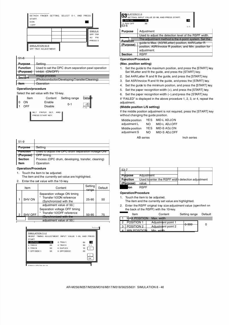
8/9/2019 AR-M318 SM
http://slidepdf.com/reader/full/ar-m318-sm 88/159
AR-M256/M257/M258/M316/M317/M318/5625/5631 SIMULATION 8 - 46
Operation/procedureSelect the set value with the 10-key.
Operation/Procedure1. Touch the item to be adjusted.
The item and the currently set value are highlighted.2. Enter the set value with the 10-key.
Operation/Procedure(Max. position setting)1. Set the guide to the maximum position, and press the [START] key.
Set WLetter and fit the guide, and press the [START] key.2. Set A4R/Letter R and fit the guide, and press the [START] key.3. Set A5R/Invoice R and fit the guide, and press the [START] key.4. Set the guide to the minimum position, and press the [START] key.5. Set the paper recognition width (+), and press the [START] key.6. Set the paper recognition width (–),and press the [START] key.If “FAILED” is displayed in the above procedure 1, 2, 3, or 4, repeat theadjustment.(Middle position L/S setting)If the middle position adjustment is not required, press the [START] keywithout changing the guide position.
Operation/Procedure1. Touch the item to be adjusted.
The item and the currently set value are highlighted.2. Enter the RSPF original tray size adjustment value (specified on
the back of the RSPF) with the 10-key.
51-8
Purpose SettingFunction(Purpose)
Used to set the OPC drum separation pawl operationinhibit. (ON/OFF)
SectionImage process(Photoconductor/Developing/Transfer/Cleaning)
Item Operation
Item Content Setting range Default0 ON Enable
0-1 01 OFF Disable
51-9
Purpose SettingFunction(Purpose)
Used to adjust the OPC drum separation voltage ON/ OFF timing.
Section Process (OPC drum, developing, transfer, cleaning)Item Operation
Item ContentSettingrange
Default
1 SHV ON
Separation voltage ON timing* Transfer V2ON reference
(Synchronized with theadjustment value of 50.)
25-90 50
2 SHV OFF
Separation voltage OFF timing* Transfer V2OFF reference
(Synchronized with theadjustment value of 50.)
50-90 75
53
53-6
Purpose Adjustment
Function(Purpose)
Used to adjust the detection level of the RSPF width.The adjustment method is the 4-point system. Set theguide to Max. (A3/WLetter) position, A4R/Letter Rposition, A5R/Invoice R position, and Min. position foradjustment.
Section RSPF
Middle positionadjustment L
YES MID-L ADJ.ONNO MID-L ADJ.OFF
Middle positionadjustment S
YES MID-S ADJ.ONNO MID-S ADJ.OFF
AB series Inch series
53-7Purpose AdjustmentFunction(Purpose)
Used to enter the RSPF width detection adjustmentvalue.
Section RSPF
Item Content Setting range Default1 MAX POSITION Max. width
0-999 02 POSITION 1 Adjustment point 1
3 POSITION 2 Adjustment point 24 MIN POSITION Min. width
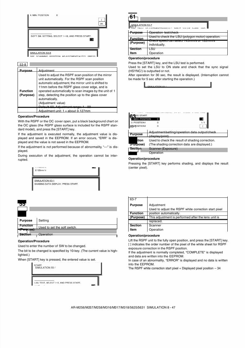
8/9/2019 AR-M318 SM
http://slidepdf.com/reader/full/ar-m318-sm 89/159
AR-M256/M257/M258/M316/M317/M318/5625/5631 SIMULATION 8 - 47
Operation/Procedure
With the RSPF or the OC cover open, put a black background chart onthe OC glass (the RSPF glass surface is included for the RSPF stan-dard model), and press the [START] key.If the adjustment is executed normally, the adjustment value is dis-played and saved in the EEPROM. If an error occurs, “ERR” is dis-played and the value is not saved in the EEPROM.If the adjustment is not performed because of abnormality, “---” is dis-played.During execution of the adjustment, the operation cannot be inter-rupted.
Operation/ProcedureUsed to enter the number of SW to be changed.The bit to be changed is specified by 10-key. (The current value is high-lighted.)When [START] key is pressed, the entered value is set.
Operation/procedurePress the [START] key, and the LSU test is performed.Used to set the LSU to ON state and check that the sync signal(HSYNC/) is outputted or not.After operation for 30 sec, the result is displayed. (Interruption cannotbe made for 5 sec after starting the operation.)
Operation/procedurePressing the [START] key performs shading, and displays the result(center pixel).
Operation/procedureLift the RSPF unit to the fully open position, and press the [START] key.[ ] indicates the order number of the pixel of the white sheet for RSPFexposure correction in the RSPF position.If the adjustment is normally completed, “COMPLETE” is displayedand data are written into the EEPROM.In case of an abnormality, “ERROR” is displayed and no data is writteninto the EEPROM.The RSPF white correction start pixel = Displayed pixel position – 34
53-8
Purpose Adjustment
Function(Purpose)
Used to adjust the RSPF scan position of the mirrorunit automatically. For the RSPF scan positionautomatic adjustment, the mirror unit is shifted to11mm before the RSPF glass cover edge, and isoperated automatically to scan images by the unit of 1step, detecting the position up to the glass coverautomatically.(Adjustment value)Default: 50, Adjustment range: 1 - 99Adjustment unit: 1 = about 0.127mm
55
55-1
Purpose Setting
Function(Purpose)
Used to set the soft switch.
Section Operation
SIMULATION 55-1
61
61-1
Purpose Operation test/check
Function(Purpose)
Used to check the LSU (polygon motor) operation.Check speed can select 145mm/s or 122mm/sindividually.
Section LSUItem Operation
63
63-1
PurposeAdjustment/setting/operation data output/check(display/print)
Function(Purpose)
Used to check the result of shading correction.(The shading correction data are displayed.)
Section Scanner (Exposure)Item Operation
63-7
Purpose Adjustment
Function(Purpose)
Used to adjust the RSPF white correction start pixelposition automatically.This adjustment is performed after the lens unit isreplaced.
Section ScannerItem Operation
SIMULATION 61-1
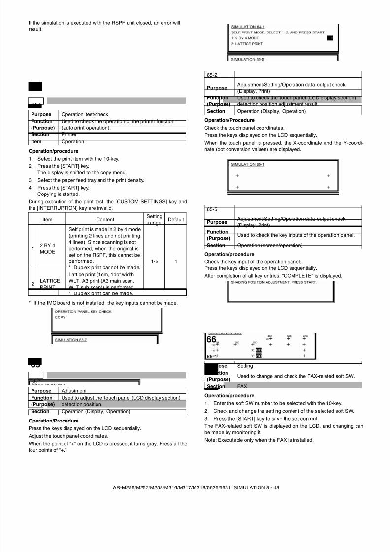
8/9/2019 AR-M318 SM
http://slidepdf.com/reader/full/ar-m318-sm 90/159
AR-M256/M257/M258/M316/M317/M318/5625/5631 SIMULATION 8 - 48
If the simulation is executed with the RSPF unit closed, an error willresult.
Operation/procedure1. Select the print item with the 10-key.2. Press the [START] key.
The display is shifted to the copy menu.3. Select the paper feed tray and the print density.4. Press the [START] key.
Copying is started.During execution of the print test, the [CUSTOM SETTINGS] key andthe [INTERRUPTION] key are invalid.
* If the IMC board is not installed, the key inputs cannot be made.
Operation/ProcedurePress the keys displayed on the LCD sequentially.Adjust the touch panel coordinates.When the point of “+” on the LCD is pressed, it turns gray. Press all thefour points of “+.”
Operation/ProcedureCheck the touch panel coordinates.Press the keys displayed on the LCD sequentially.When the touch panel is pressed, the X-coordinate and the Y-coordi-nate (dot conversion values) are displayed.
Operation/procedureCheck the key input of the operation panel.Press the keys displayed on the LCD sequentially.After completion of all key entries, “COMPLETE” is displayed.
Operation/procedure1. Enter the soft SW number to be selected with the 10-key.2. Check and change the setting content of the selected soft SW.3. Press the [START] key to save the set content.The FAX-related soft SW is displayed on the LCD, and changing canbe made by monitoring it.Note: Executable only when the FAX is installed.
64
64-1
Purpose Operation test/checkFunction(Purpose)
Used to check the operation of the printer function(auto print operation).
Section PrinterItem Operation
Item ContentSettingrange
Default
1 2 BY 4MODE
Self print is made in 2 by 4 mode(printing 2 lines and not printing4 lines). Since scanning is notperformed, when the original isset on the RSPF, this cannot beperformed.* Duplex print cannot be made.
1-2 1
2LATTICEPRINT
Lattice print (1cm, 1dot widthWLT, A3 print (A3 main scan,WLT sub scan)) is performed.* Duplex print can be made.
65
65-1
Purpose AdjustmentFunction(Purpose)
Used to adjust the touch panel (LCD display section)detection position.
Section Operation (Display, Operation)
65-2
PurposeAdjustment/Setting/Operation data output check(Display, Print)
Function(Purpose)
Used to check the touch panel (LCD display section)detection position adjustment result.
Section Operation (Display, Operation)
65-5
PurposeAdjustment/Setting/Operation data output check(Display, Print)
Function(Purpose)
Used to check the key inputs of the operation panel.
Section Operation (screen/operation)
66
66-1
Purpose SettingFunction(Purpose)
Used to change and check the FAX-related soft SW.
Section FAX
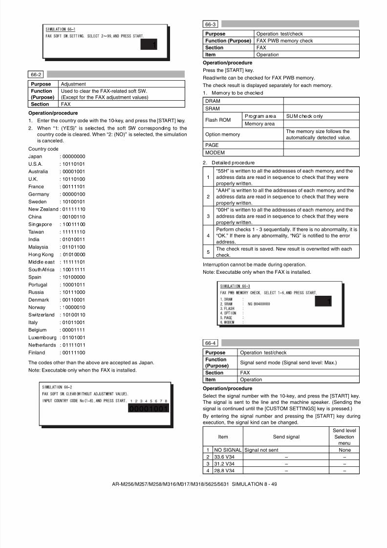
8/9/2019 AR-M318 SM
http://slidepdf.com/reader/full/ar-m318-sm 91/159
AR-M256/M257/M258/M316/M317/M318/5625/5631 SIMULATION 8 - 49
Operation/procedure1. Enter the country code with the 10-key, and press the [START] key.2. When “1: (YES)” is selected, the soft SW corresponding to the
country code is cleared. When “2: (NO)” is selected, the simulationis canceled.
Country code
The codes other than the above are accepted as Japan.Note: Executable only when the FAX is installed.
Operation/procedurePress the [START] key.Read/write can be checked for FAX PWB memory.The check result is displayed separately for each memory.1. Memory to be checked
2. Detailed procedure
Interruption cannot be made during operation.Note: Executable only when the FAX is installed.
Operation/procedureSelect the signal number with the 10-key, and press the [START] key.The signal is sent to the line and the machine speaker. (Sending thesignal is continued until the [CUSTOM SETTINGS] key is pressed.)By entering the signal number and pressing the [START] key duringexecution, the signal kind can be changed.
66-2
Purpose AdjustmentFunction(Purpose)
Used to clear the FAX-related soft SW.(Except for the FAX adjustment values)
Section FAX
Japan : 00000000U.S.A. : 10110101Australia : 00001001U.K. : 10110100France : 00111101Germany : 00000100Sweden : 10100101New Zealand : 01111110China : 00100110Singapore : 10011100Taiwan : 11111110India : 01010011Malaysia : 01101100Hong Kong : 01010000Middle east : 11111101SouthAfrica : 10011111Spain : 10100000Portugal : 10001011Russia : 10111000Denmark : 00110001Norway : 10000010Switzerland : 10100110Italy : 01011001Belgium : 00001111Luxembourg : 01101001Netherlands : 01111011Finland : 00111100
1
000010011 2 3 4 5 6 7 8
66-3
Purpose Operation test/checkFunction (Purpose) FAX PWB memory checkSection FAXItem Operation
DRAMSRAM
Flash ROMProgram area SUM check onlyMemory area
Option memory The memory size follows theautomatically detected value.
PAGEMODEM
1“55H” is written to all the addresses of each memory, and theaddress data are read in sequence to check that they wereproperly written.
2 “AAH” is written to all the addresses of each memory, and theaddress data are read in sequence to check that they wereproperly written.
3“00H” is written to all the addresses of each memory, and theaddress data are read in sequence to check that they wereproperly written.
4Perform checks 1 - 3 sequentially. If there is no abnormality, it is“OK.” If there is any abnormality, “NG” is notified to the erroraddress.
5The check result is saved. New result is overwrited with eachcheck.
66-4
Purpose Operation test/checkFunction(Purpose)
Signal send mode (Signal send level: Max.)
Section FAXItem Operation
Item Send signalSend levelSelection
menu1 NO SIGNAL Signal not sent None2 33.6 V34 – –3 31.2 V34 – –4 28.8 V34 – –
1
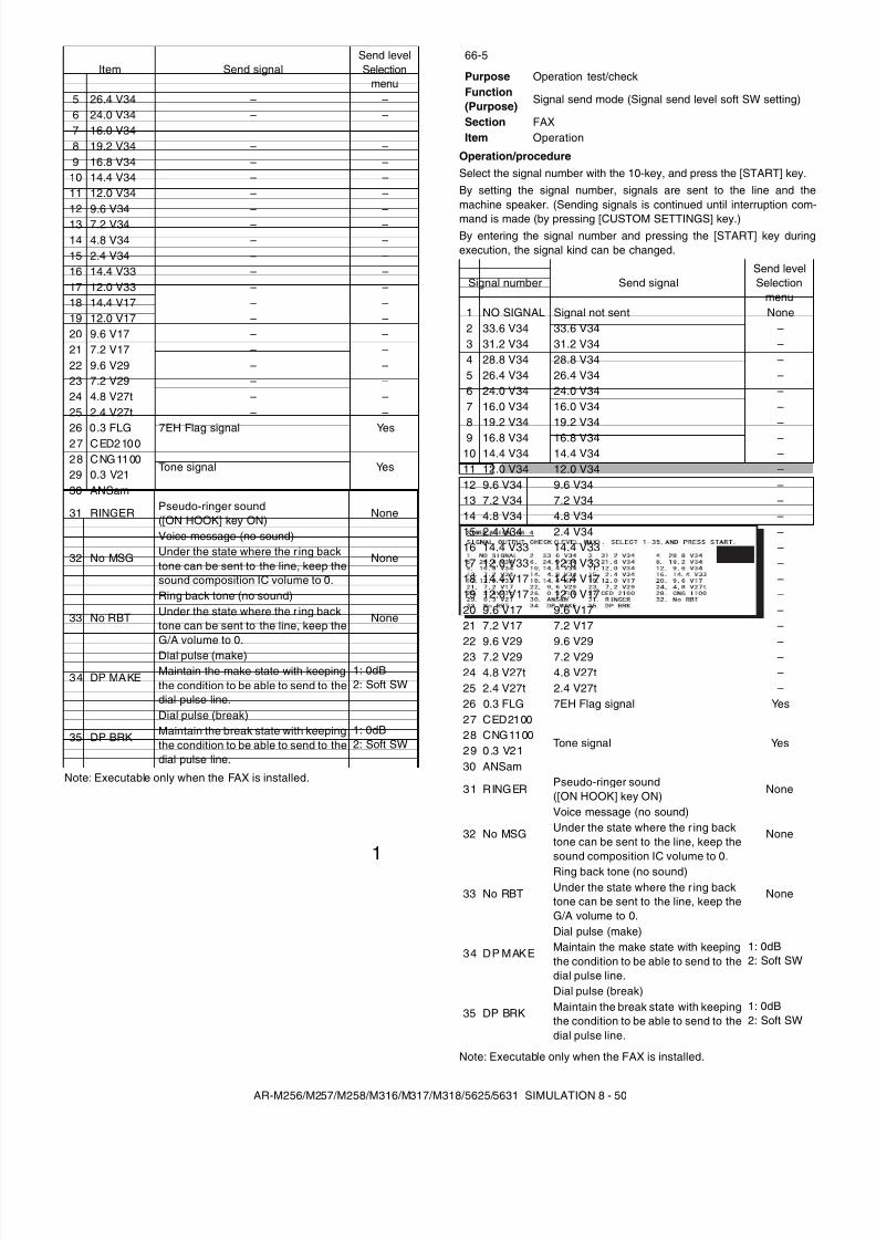
8/9/2019 AR-M318 SM
http://slidepdf.com/reader/full/ar-m318-sm 92/159
AR-M256/M257/M258/M316/M317/M318/5625/5631 SIMULATION 8 - 50
Note: Executable only when the FAX is installed.
Operation/procedureSelect the signal number with the 10-key, and press the [START] key.By setting the signal number, signals are sent to the line and themachine speaker. (Sending signals is continued until interruption com-mand is made (by pressing [CUSTOM SETTINGS] key.)By entering the signal number and pressing the [START] key duringexecution, the signal kind can be changed.
Note: Executable only when the FAX is installed.
5 26.4 V34 – –6 24.0 V34 – –7 16.0 V34 – –8 19.2 V34 – –9 16.8 V34 – –
10 14.4 V34 – –11 12.0 V34 – –12 9.6 V34 – –13 7.2 V34 – –14 4.8 V34 – –15 2.4 V34 – –16 14.4 V33 – –17 12.0 V33 – –18 14.4 V17 – –19 12.0 V17 – –20 9.6 V17 – –21 7.2 V17 – –22 9.6 V29 – –23 7.2 V29 – –24 4.8 V27t – –25 2.4 V27t – –26 0.3 FLG 7EH Flag signal Yes27 CED2100
Tone signal Yes28 CNG110029 0.3 V2130 ANSam
31 RINGER Pseudo-ringer sound([ON HOOK] key ON)
None
32 No MSG
Voice message (no sound)
NoneUnder the state where the r ing backtone can be sent to the line, keep thesound composition IC volume to 0.
33 No RBT
Ring back tone (no sound)
NoneUnder the state where the r ing backtone can be sent to the line, keep theG/A volume to 0.
34 DP MAKE
Dial pulse (make)1: 0dB2: Soft SW
Maintain the make state with keepingthe condition to be able to send to thedial pulse line.
35 DP BRK
Dial pulse (break)1: 0dB2: Soft SW
Maintain the break state with keepingthe condition to be able to send to thedial pulse line.
Item Send signalSend levelSelection
menu
1
66-5
Purpose Operation test/checkFunction(Purpose)
Signal send mode (Signal send level soft SW setting)
Section FAXItem Operation
Signal number Send signalSend levelSelection
menu1 NO SIGNAL Signal not sent None2 33.6 V34 33.6 V34 –3 31.2 V34 31.2 V34 –4 28.8 V34 28.8 V34 –5 26.4 V34 26.4 V34 –6 24.0 V34 24.0 V34 –7 16.0 V34 16.0 V34 –8 19.2 V34 19.2 V34 –9 16.8 V34 16.8 V34 –
10 14.4 V34 14.4 V34 –11 12.0 V34 12.0 V34 –12 9.6 V34 9.6 V34 –13 7.2 V34 7.2 V34 –14 4.8 V34 4.8 V34 –15 2.4 V34 2.4 V34 –16 14.4 V33 14.4 V33 –17 12.0 V33 12.0 V33 –18 14.4 V17 14.4 V17 –19 12.0 V17 12.0 V17 –20 9.6 V17 9.6 V17 –21 7.2 V17 7.2 V17 –22 9.6 V29 9.6 V29 –23 7.2 V29 7.2 V29 –24 4.8 V27t 4.8 V27t –25 2.4 V27t 2.4 V27t –26 0.3 FLG 7EH Flag signal Yes27 CED2100
Tone signal Yes28 CNG110029 0 .3 V2130 ANSam
31 RINGERPseudo-ringer sound([ON HOOK] key ON)
None
32 No MSG
Voice message (no sound)
NoneUnder the state where the r ing backtone can be sent to the line, keep thesound composition IC volume to 0.
33 No RBT
Ring back tone (no sound)
NoneUnder the state where the r ing backtone can be sent to the line, keep theG/A volume to 0.
34 DP MAKE
Dial pulse (make)1: 0dB2: Soft SW
Maintain the make state with keepingthe condition to be able to send to thedial pulse line.
35 DP BRK
Dial pulse (break)1: 0dB2: Soft SW
Maintain the break state with keepingthe condition to be able to send to thedial pulse line.
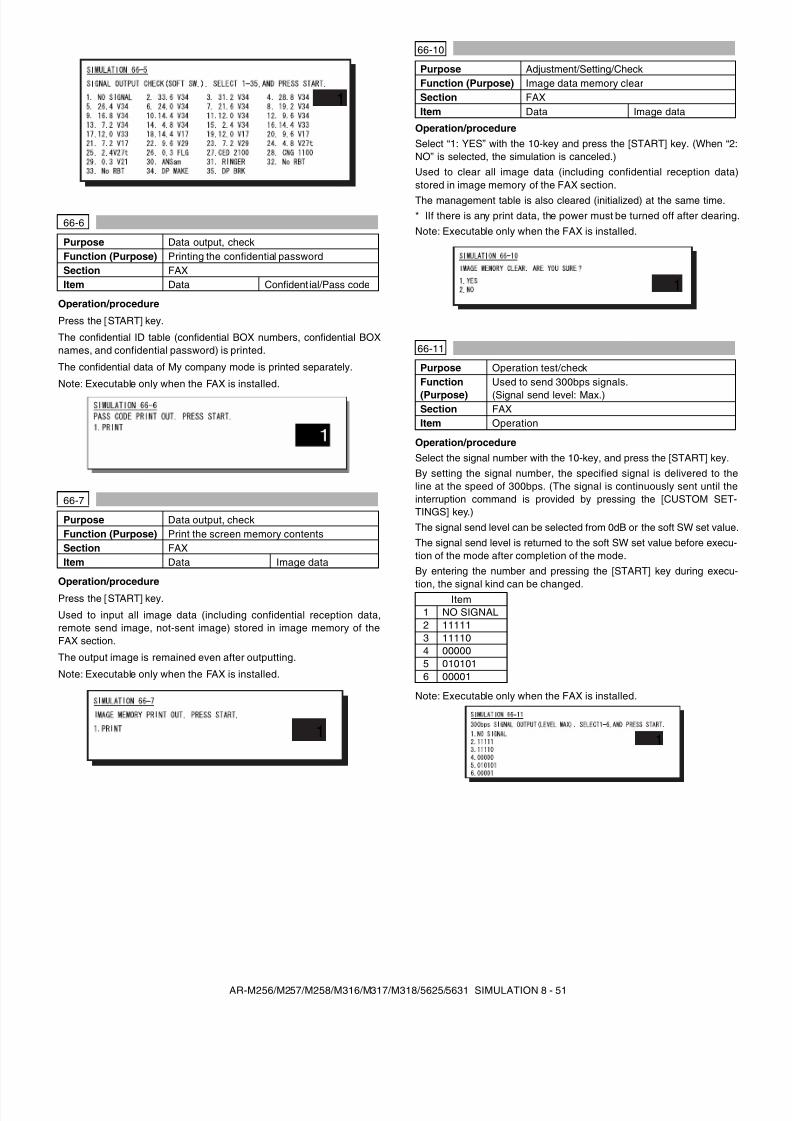
8/9/2019 AR-M318 SM
http://slidepdf.com/reader/full/ar-m318-sm 93/159
AR-M256/M257/M258/M316/M317/M318/5625/5631 SIMULATION 8 - 51
Operation/procedure
Press the [START] key.
The confidential ID table (confidential BOX numbers, confidential BOXnames, and confidential password) is printed.
The confidential data of My company mode is printed separately.
Note: Executable only when the FAX is installed.
Operation/procedure
Press the [START] key.
Used to input all image data (including confidential reception data,remote send image, not-sent image) stored in image memory of theFAX section.
The output image is remained even after outputting.
Note: Executable only when the FAX is installed.
Operation/procedureSelect “1: YES” with the 10-key and press the [START] key. (When “2:NO” is selected, the simulation is canceled.)Used to clear all image data (including confidential reception data)stored in image memory of the FAX section.The management table is also cleared (initialized) at the same time.* lIf there is any print data, the power must be turned off after clearing.Note: Executable only when the FAX is installed.
Operation/procedureSelect the signal number with the 10-key, and press the [START] key.By setting the signal number, the specified signal is delivered to theline at the speed of 300bps. (The signal is continuously sent until theinterruption command is provided by pressing the [CUSTOM SET-TINGS] key.)The signal send level can be selected from 0dB or the soft SW set value.The signal send level is returned to the soft SW set value before execu-tion of the mode after completion of the mode.By entering the number and pressing the [START] key during execu-
tion, the signal kind can be changed.
Note: Executable only when the FAX is installed.
66-6
Purpose Data output, checkFunction (Purpose) Printing the confidential passwordSection FAXItem Data Confident ial/Pass code
66-7
Purpose Data output, checkFunction (Purpose) Print the screen memory contentsSection FAXItem Data Image data
1
1
66-10
Purpose Adjustment/Setting/CheckFunction (Purpose) Image data memory clearSection FAXItem Data Image data
66-11
Purpose Operation test/checkFunction(Purpose)
Used to send 300bps signals.(Signal send level: Max.)
Section FAXItem Operation
Item1 NO SIGNAL2 111113 111104 000005 0101016 00001
1
1
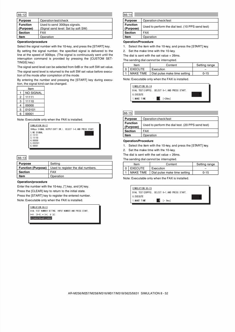
8/9/2019 AR-M318 SM
http://slidepdf.com/reader/full/ar-m318-sm 94/159
AR-M256/M257/M258/M316/M317/M318/5625/5631 SIMULATION 8 - 52
Operation/procedureSelect the signal number with the 10-key, and press the [START] key.By setting the signal number, the specified signal is delivered to theline at the speed of 300bps. (The signal is continuously sent until theinterruption command is provided by pressing the [CUSTOM SET-TINGS] key.)The signal send level can be selected from 0dB or the soft SW set value.The signal send level is returned to the soft SW set value before execu-tion of the mode after completion of the mode.By entering the number and pressing the [START] key during execu-tion, the signal kind can be changed.
Note: Executable only when the FAX is installed.
Operation/procedureEnter the number with the 10-key, [*] key, and [#] key.Press the [CLEAR] key to return to the initial state.Press the [START] key to register the entered number.Note: Executable only when the FAX is installed.
Operation/Procedure1. Select the item with the 10-key, and press the [START] key.2. Set the make time with the 10-key.The dial is sent with the set value + 26ms.The sending dial cannot be interrupted.
Note: Executable only when the FAX is installed.
Operation/Procedure1. Select the item with the 10-key, and press the [START] key.2. Set the make time with the 10-key.The dial is sent with the set value + 26ms.The sending dial cannot be interrupted.
Note: Executable only when the FAX is installed.
66-12
Purpose Operation test/checkFunction(Purpose)
Used to send 300bps signals.(Signal send level: Set by soft SW)
Section FAXItem Operation
Item1 NO SIGNAL2 111113 111104 000005 0101016 00001
66-13
Purpose SettingFunction (Purpose) Used to register the dial numbers.Section FAXItem Operation
1
66-14
Purpose Operation check/testFunction(Purpose)
Used to perform the dial test. (10 PPS send test)
Section FAXItem Operation
Item Content Setting range0 EXECUTE Execution –1 MAKE TIME Dial pulse make time setting 0-15
66-15
Purpose Operation check/testFunction(Purpose)
Used to perform the dial test. (20 PPS send test)
Section FAXItem Operation
Item Content Setting range0 EXECUTE Execution –1 MAKE TIME Dial pulse make time setting 0-15
1
1
8/9/2019 AR-M318 SM
http://slidepdf.com/reader/full/ar-m318-sm 95/159
AR-M256/M257/M258/M316/M317/M318/5625/5631 SIMULATION 8 - 53
Operation/Procedure1. Select the item with the 10-key, and press the [START] key.2. Enter the set value with the 10-key.The sending dial cannot be interrupted.
3. Select the soft SW reflection.
Note: Executable only when the FAX is installed.
Operation/procedureEnter the DTFM signal (1 digit (1 to 9, 0, *, #)) and press the [START] key.When the [CUSTOM SETTINGS] key is pressed during execution, thesimulation is terminated.Note: Executable only when the FAX is installed.
Operation/ProcedureEnter the DTFM signal (1 digit (1 to 9, 0, *, #)) and press the [START] key.When the [CUSTOM SETTINGS] key is pressed during execution, thesimulation is terminated.Note: Executable only when the FAX is installed.
Operation/ProcedureSelect “1: YES” with the 10-key, and press the [START] key. The dataare backed up. (When “2: NO” is selected, the simulation is canceled.)* The AR-FX5 data cannot be written into the AR-FX7. If it is exe-
cuted, data are initialized and deleted. In addition, the AR-FX7 datacannot be used in the AR-FX5.
Note: Executable only when the FAX is installed.
Operation/ProcedureSelect “1: YES” with the 10-key, and press the [START] key. The FlashROM data are read out and written into the SRAM. (When “2: NO” isselected, the simulation is canceled.)* The AR-FX5 data cannot be written into the AR-FX7. If it is exe-
cuted, data are initialized and deleted. In addition, the AR-FX7 datacannot be used in the AR-FX5.
Note: Executable only when the FAX is installed.
Operation/procedure1. Select the item to be printed.2. Press the [START] key.The information of the selected item is printed.
Note: Executable only when the FAX is installed.
66-16
Purpose Operation check/testFunction(Purpose)
Used to perform the dial test. (DTFM signal send test)
Section FAXItem Operation
Item ContentSettingrange
0 EXECUTE Execution –1 HIGH (SW) High group 0-152 HIGH-LOW (SW) High group, Low group 0-15
Item Content1 NO STORE TO SW Not reflected.2 STORE TO SW Reflected. (Shift SW value changed.)
66-17
Purpose Operation check/testFunction(Purpose)
Used to check the DTFM signal send operation.(Signal send level: Max.)
Section FAXItem Operation
66-18
Purpose Operation check/testFunction(Purpose)
Used to check the DTFM signal send operation.(Signal send level: Set by soft SW.)
Section FAXItem Operation
1
66-19
Purpose Back upFunction(Purpose)
Used to write the SRAM data to the Flash ROM.
Section FAXItem Data
66-20
Purpose Back upFunction(Purpose)
Used to write the Flash ROM data to the SRAM.
Section FAXItem Data
66-21
Purpose CheckFunction (Purpose) FAX information printSection FAXItem Data
Item Content
1 USER SW.LIST User setting list2 SOFT SW.LIST Soft SW list
3 SYSTEM ERRORSystem error listUsed to print the system error log (errornumber and time).
4 PROTOCOL
Protocol error listRegardless of soft SW38-1 status, theprotocol monitor of the precedingcommunication is printed. (Printing isallowed at any time before starting thenext communication.) For this operation,the protocol monitor of onecommunication is always buffered.
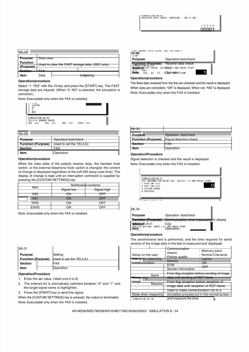
8/9/2019 AR-M318 SM
http://slidepdf.com/reader/full/ar-m318-sm 96/159
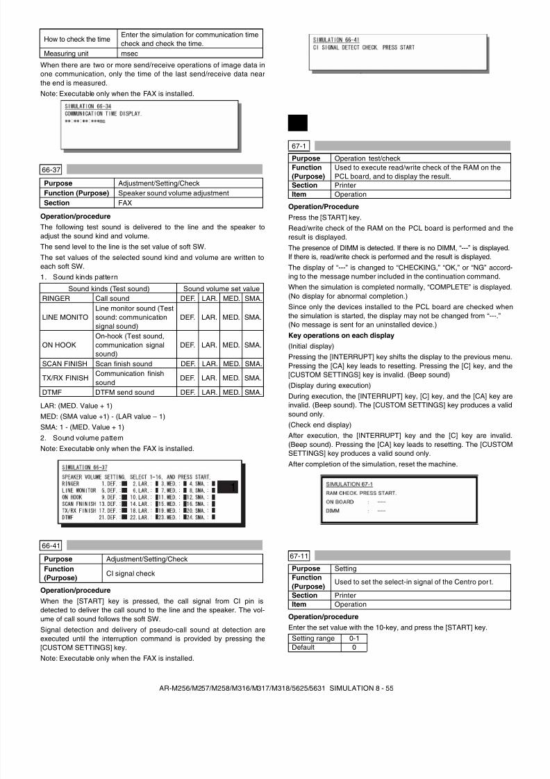
8/9/2019 AR-M318 SM
http://slidepdf.com/reader/full/ar-m318-sm 97/159
AR-M256/M257/M258/M316/M317/M318/5625/5631 SIMULATION 8 - 55
When there are two or more send/receive operations of image data inone communication, only the time of the last send/receive data nearthe end is measured.Note: Executable only when the FAX is installed.
Operation/procedureThe following test sound is delivered to the line and the speaker toadjust the sound kind and volume.The send level to the line is the set value of soft SW.The set values of the selected sound kind and volume are written toeach soft SW.1. Sound kinds pattern
LAR: (MED. Value + 1)MED: (SMA value +1) - (LAR value – 1)SMA: 1 - (MED. Value + 1)2. Sound volume patternNote: Executable only when the FAX is installed.
Operation/procedureWhen the [START] key is pressed, the call signal from CI pin isdetected to deliver the call sound to the line and the speaker. The vol-ume of call sound follows the soft SW.Signal detection and delivery of pseudo-call sound at detection areexecuted until the interruption command is provided by pressing the[CUSTOM SETTINGS] key.Note: Executable only when the FAX is installed.
Operation/ProcedurePress the [START] key.Read/write check of the RAM on the PCL board is performed and theresult is displayed.The presence of DIMM is detected. If there is no DIMM, “---” is displayed.If there is, read/write check is performed and the result is displayed.The display of “---” is changed to “CHECKING,” “OK,” or “NG” accord-ing to the message number included in the continuation command.When the simulation is completed normally, “COMPLETE” is displayed.(No display for abnormal completion.)Since only the devices installed to the PCL board are checked whenthe simulation is started, the display may not be changed from “---.”(No message is sent for an uninstalled device.)Key operations on each display(Initial display)Pressing the [INTERRUPT] key shifts the display to the previous menu.Pressing the [CA] key leads to resetting. Pressing the [C] key, and the[CUSTOM SETTINGS] key is invalid. (Beep sound)(Display during execution)During execution, the [INTERRUPT] key, [C] key, and the [CA] key areinvalid. (Beep sound). The [CUSTOM SETTINGS] key produces a validsound only.(Check end display)After execution, the [INTERRUPT] key and the [C] key are invalid.(Beep sound). Pressing the [CA] key leads to resetting. The [CUSTOMSETTINGS] key produces a valid sound only.After completion of the simulation, reset the machine.
Operation/procedureEnter the set value with the 10-key, and press the [START] key.
How to check the timeEnter the simulation for communication timecheck and check the time.
Measuring unit msec
66-37
Purpose Adjustment/Setting/CheckFunction (Purpose) Speaker sound volume adjustmentSection FAX
Sound kinds (Test sound) Sound volume set valueRINGER Call sound DEF. LAR. MED. SMA.
LINE MONITOLine monitor sound (Testsound: communicationsignal sound)
DEF. LAR. MED. SMA.
ON HOOKOn-hook (Test sound,communication signalsound)
DEF. LAR. MED. SMA.
SCAN FINISH Scan finish sound DEF. LAR. MED. SMA.
TX/RX FINISHCommunication finishsound
DEF. LAR. MED. SMA.
DTMF DTFM send sound DEF. LAR. MED. SMA.
66-41Purpose Adjustment/Setting/CheckFunction(Purpose)
CI signal check
1
67
67-1
Purpose Operation test/checkFunction(Purpose)
Used to execute read/write check of the RAM on thePCL board, and to display the result.
Section PrinterItem Operation
67-11
Purpose SettingFunction(Purpose)
Used to set the select-in signal of the Centro por t.
Section PrinterItem Operation
Setting range 0-1Default 0
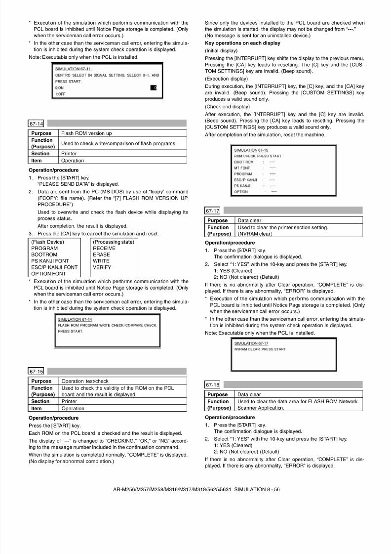
8/9/2019 AR-M318 SM
http://slidepdf.com/reader/full/ar-m318-sm 98/159
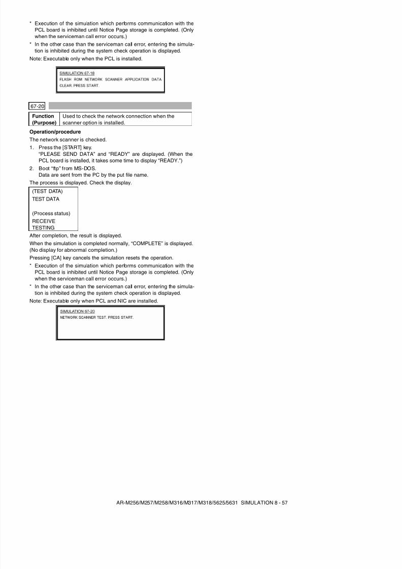
8/9/2019 AR-M318 SM
http://slidepdf.com/reader/full/ar-m318-sm 99/159
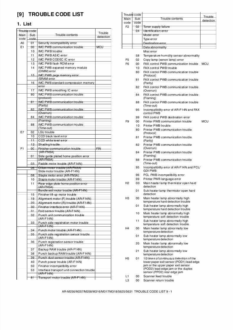
8/9/2019 AR-M318 SM
http://slidepdf.com/reader/full/ar-m318-sm 100/159
AR-M256/M257/M258/M316/M317/M318/5625/5631 TROUBLE CODE LIST 9 - 1
[9] TROUBLE CODE LIST
1. ListTrouble code
Trouble contents TroubledetectionMain
codeSubcode
A0 01 Secur ity incompatibility errorE1 00 IMC PWB communication trouble MCU
10 IMC PWB trouble11 IMC PWB ASIC error12 IMC PWB CODEC IC error13 IMC PWB flash ROM error14 IMC PWB expaned memory module
(DIMM) error15 IMC PWB page memory error
/SRAM error16 IMC PWB standard compression memory
error17 IMC PWB smoothing IC error80 IMC PWB communication trouble
(protocol)81 IMC PWB communication trouble
(Parity)82 IMC PWB communication trouble
(Overrun)84 IMC PWB communication trouble
(Framing)88 IMC PWB communication trouble
(Time-out)E7 02 LSU trouble
10 CCD black level error11 CCD white level error12 Shading trouble
F1 00 Finishe r communication trouble (AR-FN5A)
FIN
01 Side guide plated home position error(AR-FN5A)
03 Paddle motor trouble (AR-F14N)06 Offset motor trouble (AR-FN5A)
Slide motor trouble (AR-F14N)08 Staple motor error (AR-FN5A)10 Staple motor trouble (AR-F14N)11 Rear edge plate home position error
(AR-FN5A)Bundle exit motor trouble (AR-F14N)
15 Finisher lift-up motor trouble19 Alignment motor (F) trouble (AR-F14N)20 Alignment motor (R) trouble (AR-F14N)30 Finisher interface error (AR-F14N)31 Fold sensor trouble (AR-F14N)32 Punch unit communication trouble
(AR-F14N)33 Punch side registration motor trouble
(AR-F14N)
34 Punch motor trouble (AR-F14N)35 Punch side registration sensor trouble(AR-F14N)
36 Punch registration sensor trouble(AR-F14N)
37 Backup RAM trouble (AR-F14N)38 Punch backup RAM trouble (AR-F14N)39 Punch dust sensor trouble (AR-F14N)40 Punch power trouble (AR-F14N)50 Finisher incompatibility error53 Interface transport unit connection trouble
(AR-F14N)81 Transport motor trouble (AR-F14N)
F2 02 Toner supply failure04 Identification error
Model errorType er rorDestination errorData abnormalityMisc error
58 Temperature humidity sensor abnormalityF5 02 Copy lamp (xenon lamp) errorF6 00 FAX control PWB communication trouble MCU
10 FAX control PWB trouble80 FAX control PWB communication trouble
(Protocol)81 FAX control PWB communication trouble
(Parity)82 FAX control PWB communication trouble
(Overrun)84 FAX control PWB communication trouble
(Framing)88 FAX control PWB communication trouble
(Time-out)95 Incompatibility error of AR-F14N and FAX
control PWB99 FAX control PWB destination error
F9 00 Printer PWB communication trouble MCU10 Printer PWB trouble80 Printer PWB communication trouble
(Protocol)81 Printer PWB communication trouble
(Parity)82 Printer PWB communication trouble
(Overrun)84 Printer PWB communication trouble
(Framing)88 Printer PWB communication trouble
(Time-out)95 Incompatibility error of AR-F14N and PCL/
GDI PWB96 PCL PWB incompatibility error99 Printer PWB language error
H2 00 Main heater lamp thermistor open harddetection
01 Sub heater lamp thermistor open harddetection
H3 00 Main heater lamp abnormally hightemperature hard detection trouble
01 Sub heater lamp abnormally hightemperature hard detection trouble
10 Main heater lamp abnormally hightemperature soft detection trouble
11 Sub heater lamp abnormally hightemperature soft detection trouble
H4 00 Main heater lamp abnormally lowtemperature detection
01 Sub heater lamp abnormally lowtemperature detection
20 Main heater lamp abnormally lowtemperature detection
21 Sub heater lamp abnormally lowtemperature detection
H5 01 10 t imes o f cont inuous detect ion o f thelower paper exit sensor (POD1) lead edge
jam or the up per paper exit sensor(POD2) lead edge jam or the duplexsensor (PPD2) rear edge jam
L1 00 Scanner feed troubleL3 00 Scanner return trouble
Trouble codeTrouble contents
TroubledetectionMain
codeSubcode
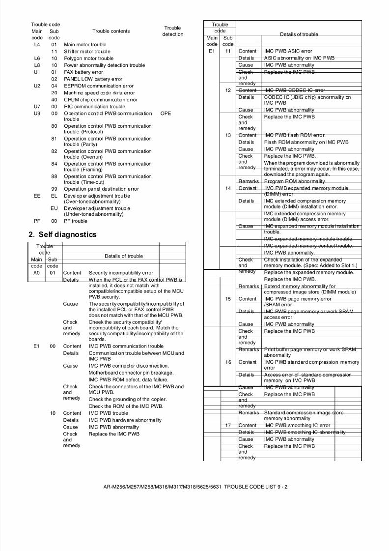
8/9/2019 AR-M318 SM
http://slidepdf.com/reader/full/ar-m318-sm 101/159
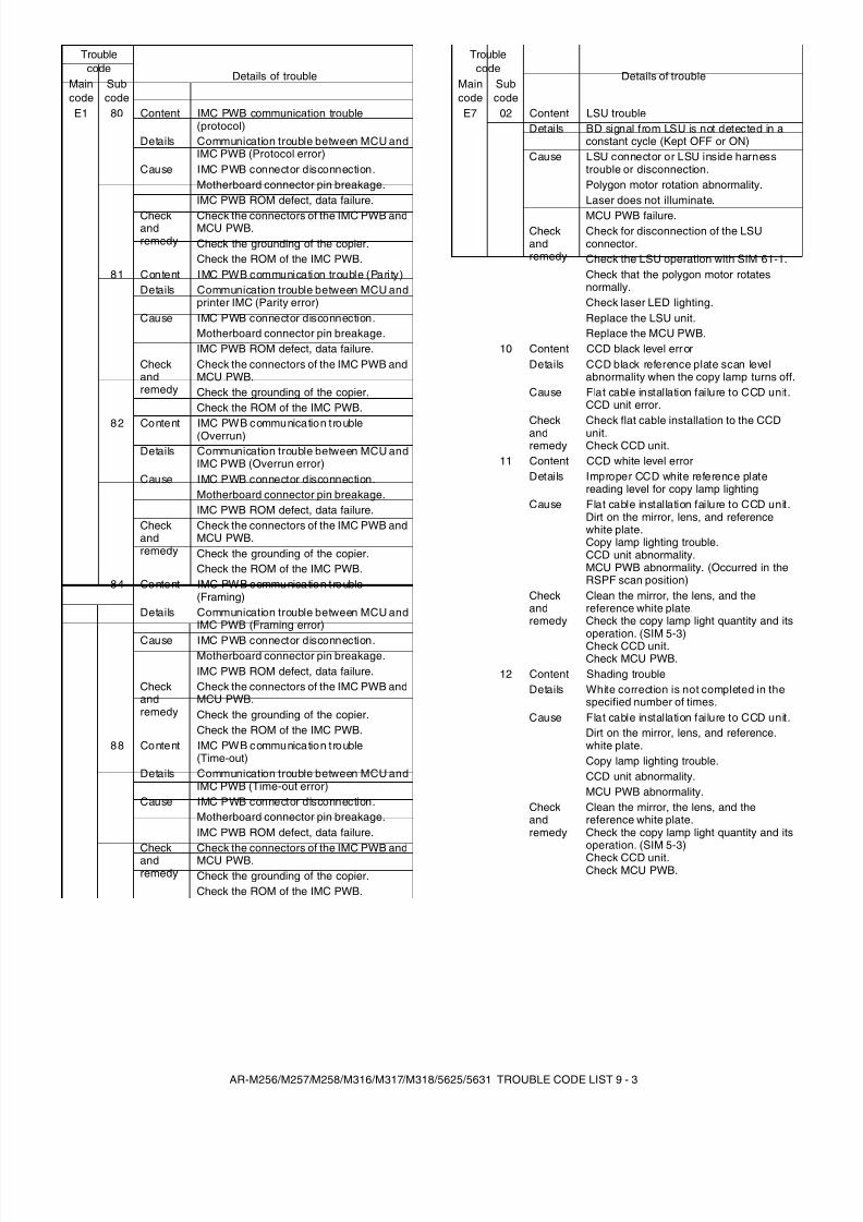
8/9/2019 AR-M318 SM
http://slidepdf.com/reader/full/ar-m318-sm 102/159
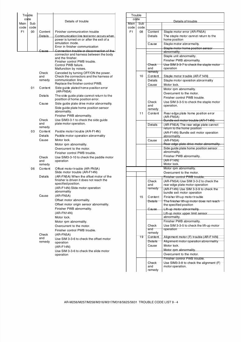
8/9/2019 AR-M318 SM
http://slidepdf.com/reader/full/ar-m318-sm 103/159
AR-M256/M257/M258/M316/M317/M318/5625/5631 TROUBLE CODE LIST 9 - 4
F1 00 Content Finisher communication troubleDetails Communication line test error occurs when
power is turned on or after the exit of asimulation mode.Error in finisher communication
Cause Connection trouble or disconnection of theconnector and harness between the bodyand the finisher.Finisher control PWB trouble.Control PWB failure.Malfunction by noises.
Checkandremedy
Canceled by turning OFF/ON the power.Check the connectors and the harness ofcommunication line.Replace the finisher control PWB.
01 Content Side guide plated home posit ion error (AR-FN5A)
Details The side guide plate cannot return to theposittion of home position error.
Cause Side guide plate drive motor abnormality.Side guide plate home position sensorabnormality.Finisher PWB abnormality.
Checkandremedy
Use SIM3-3-1 to check the side guideplate motor operation.
03 Content Paddle motor t rouble (AR-F14N)Details Paddle motor operation abnormalityCause Motor lock.
Motor rpm abnormality.Overcurrent to the motor.Finisher control PWB trouble.
Checkandremedy
Use SIM3-3-10 to check the paddle motoroperation
06 Content Offset motor trouble (AR-FN5A)Slide motor trouble (AR-F14N)
Details (AR-FN5A) When the offset motor of thefinisher is driven it does not reach thespecified position.(AR-F14N) Slide motor operationabnormality
Cause (AR-FN5A)Offset motor abnormality.Offset motor origin sensor abnormality.Finisher PWB abnormality.(AR-FN14N)Motor lock.Motor rpm abnormality.Overcurrent to the motor.Finisher control PWB trouble.
Check
andremedy
(AR-FN5A)
Use SIM 3-3-6 to check the offset motoroperation(AR-F14N)Use SIM 3-3-6 to check the slide motoroperation
Troublecode
Details of troubleMaincode
Subcode
F1 08 Content Staple motor error (AR-FN5A)Details The staple motor cannot return to the
home positionCause Staple motor abnormality.
Staple motor home position sensorabnormality.Staple unit abnormality.
Finisher PWB abnormality.Checkandremedy
Use SIM 3-3-7 to check the staple motoroperation
10 Content Staple motor trouble (AR-F14N)Details Staple motor operation abnormalityCause Motor lock.
Motor rpm abnormality.Overcurrent to the motor.Finisher control PWB trouble.
Checkandremedy
Use SIM 3-3-5 to check the staple motoroperation.
11 Content Rear edge plate home position error(AR-FN5A)Bundle exit motor trouble (AR-F14N)
Details (AR-FN5A) The rear edge plate cannotreturn to the home position(AR-F14N) Bundle exit motor operationabnormality
Cause (AR-FN5A)Rear edge plate drive motor abnormality.Side guide plate home position sensorabnormality.Finisher PWB abnormality.(AR-F14N)Motor lock.Motor rpm abnormality.Overcurrent to the motor.Finisher control PWB trouble.
Checkandremedy
(AR-FN5A) Use SIM 3-3-2 to check therear edge plate motor operation(AR-F14N) Use SIM 3-3-9 to check thebundle exit motor operation
15 Conten t Fin isher lif t-up motor troubleDetails The finisher lift-up motor does not reach
the specified positionCause Lift-up motor abnormality.
Lift-up motor upper limit sensorabnormality.Finisher PWB abnormality.
Checkandremedy
Use SIM 3-3-5 to check the lift-up motoroperation
19 Content Alignment motor (F) trouble (AR-F14N)Details Alignment motor operation abnormalityCause Motor lock.
Motor rpm abnormality.Overcurrent to the motor.Finisher control PWB trouble.
Checkandremedy
Use SIM3-3-8 to check the alignment (F)motor operation.
Troublecode
Details of troubleMaincode
Subcode
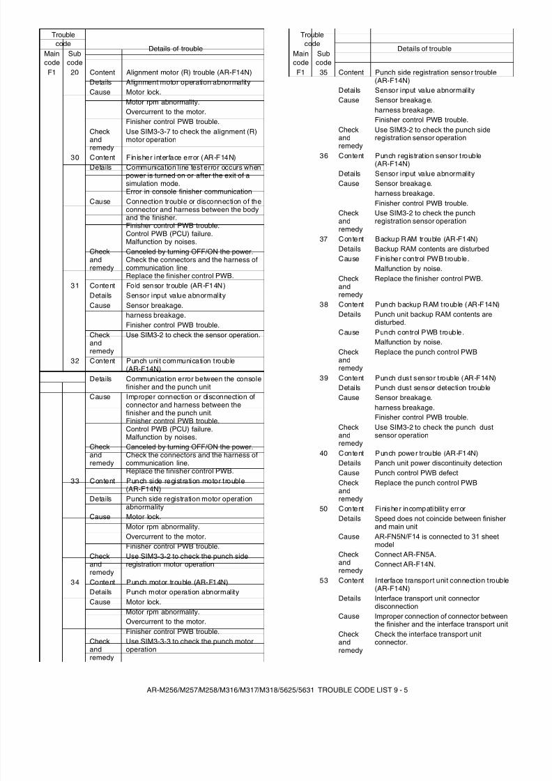
8/9/2019 AR-M318 SM
http://slidepdf.com/reader/full/ar-m318-sm 104/159
AR-M256/M257/M258/M316/M317/M318/5625/5631 TROUBLE CODE LIST 9 - 5
F1 20 Content Alignment motor (R) trouble (AR-F14N)Details Alignment motor operation abnormalityCause Motor lock.
Motor rpm abnormality.Overcurrent to the motor.Finisher control PWB trouble.
Checkandremedy
Use SIM3-3-7 to check the alignment (R)motor operation
30 Content Finisher interface error (AR-F14N)Details Communication line test error occurs when
power is turned on or after the exit of asimulation mode.Error in console finisher communication
Cause Connection trouble or disconnection of theconnector and harness between the bodyand the finisher.Finisher control PWB trouble.Control PWB (PCU) failure.Malfunction by noises.
Checkandremedy
Canceled by turning OFF/ON the power.Check the connectors and the harness ofcommunication lineReplace the finisher control PWB.
31 Content Fo ld sensor trouble (AR-F14N)Details Sensor input value abnormalityCause Sensor breakage.
harness breakage.Finisher control PWB trouble.
Checkandremedy
Use SIM3-2 to check the sensor operation.
32 Content Punch unit communication trouble(AR-F14N)
Details Communication error between the consolefinisher and the punch unit
Cause Improper connection or disconnection ofconnector and harness between thefinisher and the punch unit.Finisher control PWB trouble.Control PWB (PCU) failure.Malfunction by noises.
Checkandremedy
Canceled by turning OFF/ON the power.Check the connectors and the harness ofcommunication line.Replace the finisher control PWB.
33 Content Punch side registration motor trouble(AR-F14N)
Details Punch side registration motor operationabnormality
Cause Motor lock.Motor rpm abnormality.Overcurrent to the motor.
Finisher control PWB trouble.Checkandremedy
Use SIM3-3-2 to check the punch sideregistration motor operation
34 Content Punch motor trouble (AR-F14N)Details Punch motor operation abnormalityCause Motor lock.
Motor rpm abnormality.Overcurrent to the motor.Finisher control PWB trouble.
Checkandremedy
Use SIM3-3-3 to check the punch motoroperation
Troublecode
Details of troubleMaincode
Subcode
F1 35 Content Punch side registration senso r trouble(AR-F14N)
Details Sensor input value abnormalityCause Sensor breakag e.
harness breakage.Finisher control PWB trouble.
Checkandremedy
Use SIM3-2 to check the punch sideregistration sensor operation
36 Content Punch registration sensor trouble(AR-F14N)
Details Sensor input value abnormalityCause Sensor breakag e.
harness breakage.Finisher control PWB trouble.
Checkandremedy
Use SIM3-2 to check the punchregistration sensor operation
37 Content Backup RAM trouble (AR-F14N)Details Backup RAM contents are disturbedCause Finisher control PWB trouble.
Malfunction by noise.Checkandremedy
Replace the finisher control PWB.
38 Content Punch backup RAM trouble (AR-F14N)Details Punch unit backup RAM contents are
disturbed.Cause Punch control PWB trouble.
Malfunction by noise.Checkandremedy
Replace the punch control PWB
39 Content Punch dust sensor trouble (AR-F14N)Details Punch dust sensor detection troubleCause Sensor breakag e.
harness breakage.Finisher control PWB trouble.Checkandremedy
Use SIM3-2 to check the punch dustsensor operation
40 Content Punch power trouble (AR-F14N)Details Panch unit power discontinuity detectionCause Punch control PWB defectCheckandremedy
Replace the punch control PWB
50 Content Finisher incompatibility errorDetails Speed does not coincide between finisher
and main unitCause AR-FN5N/F14 is connected to 31 sheet
modelCheckandremedy
Connect AR-FN5A.Connect AR-F14N.
53 Content Interface transport unit connection trouble(AR-F14N)
Details Interface transport unit connectordisconnection
Cause Improper connection of connector betweenthe finisher and the interface transport unit
Checkandremedy
Check the interface transport unitconnector.
Troublecode
Details of troubleMaincode
Subcode
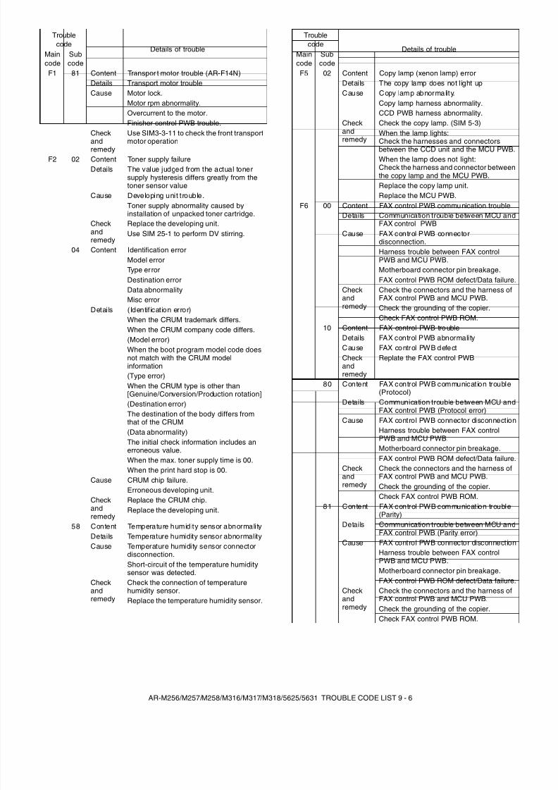
8/9/2019 AR-M318 SM
http://slidepdf.com/reader/full/ar-m318-sm 105/159
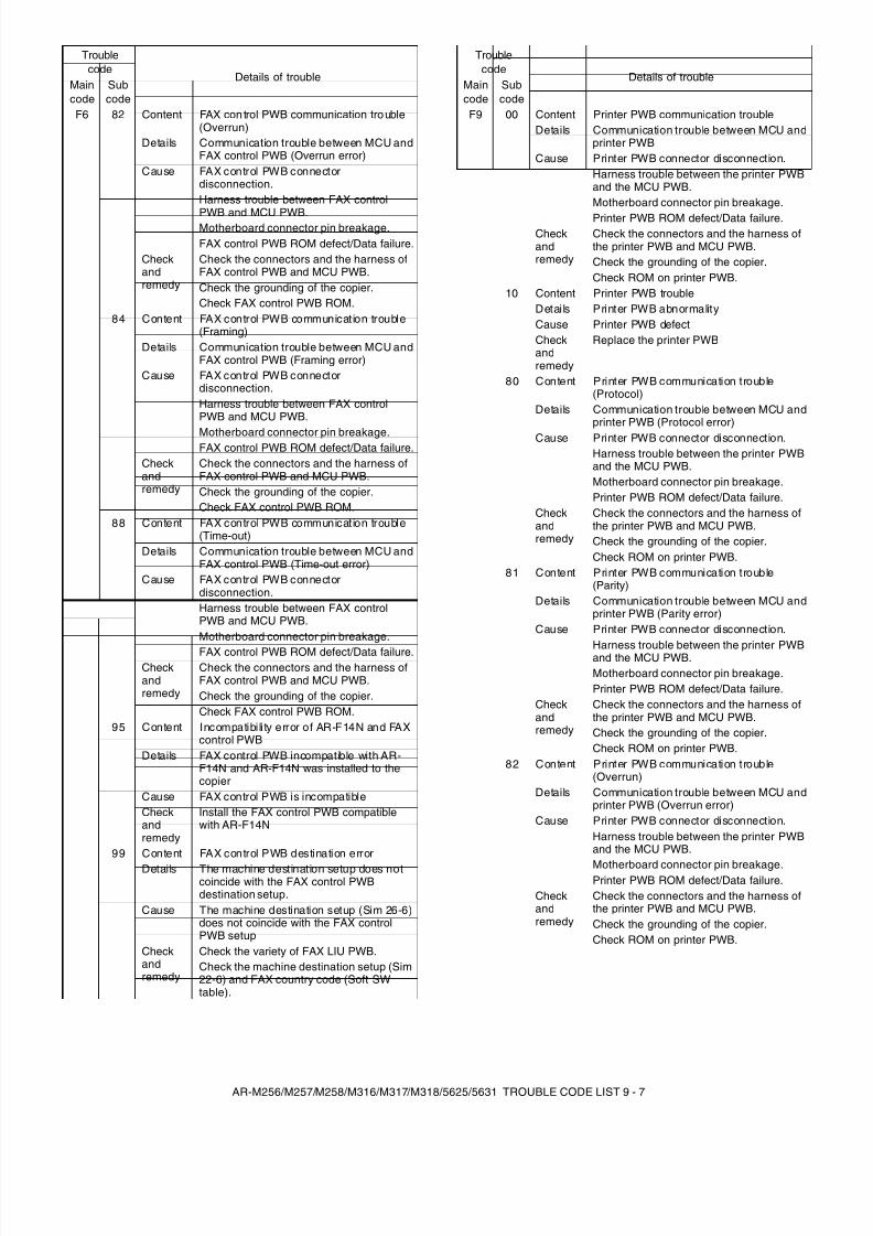
8/9/2019 AR-M318 SM
http://slidepdf.com/reader/full/ar-m318-sm 106/159
AR-M256/M257/M258/M316/M317/M318/5625/5631 TROUBLE CODE LIST 9 - 7
F6 82 Content FAX con trol PWB communication tro uble(Overrun)
Details Communication trouble between MCU andFAX control PWB (Overrun error)
Cause FAX control PWB connectordisconnection.Harness trouble between FAX control
PWB and MCU PWB.Motherboard connector pin breakage.FAX control PWB ROM defect/Data failure.
Checkandremedy
Check the connectors and the harness ofFAX control PWB and MCU PWB.Check the grounding of the copier.Check FAX control PWB ROM.
84 Content FAX control PWB communication trouble(Framing)
Details Communication trouble between MCU andFAX control PWB (Framing error)
Cause FAX control PWB connectordisconnection.Harness trouble between FAX controlPWB and MCU PWB.
Motherboard connector pin breakage.FAX control PWB ROM defect/Data failure.
Checkandremedy
Check the connectors and the harness ofFAX control PWB and MCU PWB.Check the grounding of the copier.Check FAX control PWB ROM.
88 Content FAX control PWB communication trouble(Time-out)
Details Communication trouble between MCU andFAX control PWB (Time-out error)
Cause FAX control PWB connectordisconnection.Harness trouble between FAX controlPWB and MCU PWB.Motherboard connector pin breakage.
FAX control PWB ROM defect/Data failure.Checkandremedy
Check the connectors and the harness ofFAX control PWB and MCU PWB.Check the grounding of the copier.Check FAX control PWB ROM.
95 Content Incompatibili ty error of AR-F14N and FAXcontrol PWB
Details FAX control PWB incompatible with AR-F14N and AR-F14N was installed to thecopier
Cause FAX control PWB is incompatibleCheckandremedy
Install the FAX control PWB compatiblewith AR-F14N
99 Content FAX control PWB destination error
Details The machine destination setup does notcoincide with the FAX control PWBdestination setup.
Cause The machine destination setup (Sim 26-6)does not coincide with the FAX controlPWB setup
Checkandremedy
Check the variety of FAX LIU PWB.Check the machine destination setup (Sim22-6) and FAX country code (Soft SWtable).
Troublecode
Details of troubleMaincode
Subcode
F9 00 Content Printer PWB communication troubleDetails Communication trouble between MCU and
printer PWBCause Printer PWB connector disconnection.
Harness trouble between the printer PWBand the MCU PWB.Motherboard connector pin breakage.
Printer PWB ROM defect/Data failure.Checkandremedy
Check the connectors and the harness ofthe printer PWB and MCU PWB.Check the grounding of the copier.Check ROM on printer PWB.
10 Content Printer PWB troubleDetails Printer PWB abnormalityCause Printer PWB defectCheckandremedy
Replace the printer PWB
80 Content Printer PWB communication trouble(Protocol)
Details Communication trouble between MCU andprinter PWB (Protocol error)
Cause Printer PWB connector disconnection.Harness trouble between the printer PWBand the MCU PWB.Motherboard connector pin breakage.Printer PWB ROM defect/Data failure.
Checkandremedy
Check the connectors and the harness ofthe printer PWB and MCU PWB.Check the grounding of the copier.Check ROM on printer PWB.
81 Content Printer PWB communication trouble(Parity)
Details Communication trouble between MCU andprinter PWB (Parity error)
Cause Printer PWB connector disconnection.
Harness trouble between the printer PWBand the MCU PWB.Motherboard connector pin breakage.Printer PWB ROM defect/Data failure.
Checkandremedy
Check the connectors and the harness ofthe printer PWB and MCU PWB.Check the grounding of the copier.Check ROM on printer PWB.
82 Content Printer PWB communication trouble(Overrun)
Details Communication trouble between MCU andprinter PWB (Overrun error)
Cause Printer PWB connector disconnection.Harness trouble between the printer PWBand the MCU PWB.
Motherboard connector pin breakage.Printer PWB ROM defect/Data failure.
Checkandremedy
Check the connectors and the harness ofthe printer PWB and MCU PWB.Check the grounding of the copier.Check ROM on printer PWB.
Troublecode
Details of troubleMaincode
Subcode
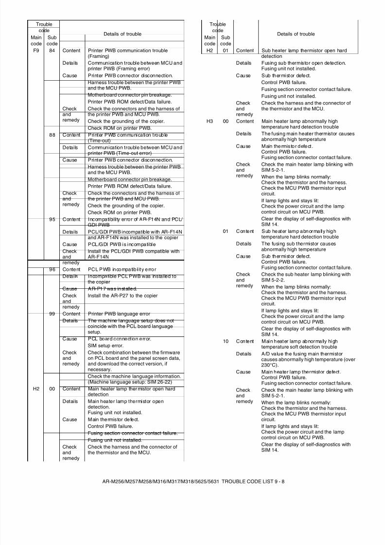
8/9/2019 AR-M318 SM
http://slidepdf.com/reader/full/ar-m318-sm 107/159
AR-M256/M257/M258/M316/M317/M318/5625/5631 TROUBLE CODE LIST 9 - 8
F9 84 Content Printer PWB communication trouble(Framing)
Details Communication trouble between MCU andprinter PWB (Framing error)
Cause Printer PWB connector disconnection.Harness trouble between the printer PWBand the MCU PWB.
Motherboard connector pin breakage.Printer PWB ROM defect/Data failure.
Checkandremedy
Check the connectors and the harness ofthe printer PWB and MCU PWB.Check the grounding of the copier.Check ROM on printer PWB.
88 Content Printer PWB communication trouble(Time-out)
Details Communication trouble between MCU andprinter PWB (Time-out error)
Cause Printer PWB connector disconnection.Harness trouble between the printer PWBand the MCU PWB.Motherboard connector pin breakage.Printer PWB ROM defect/Data failure.
Checkandremedy
Check the connectors and the harness ofthe printer PWB and MCU PWB.Check the grounding of the copier.Check ROM on printer PWB.
95 Content Incompatibili ty error of AR-F14N and PCL/ GDI PWB
Details PCL/GDI PWB incompatible with AR-F14Nand AR-F14N was installed to the copier
Cause PCL/GDI PWB is incompatibleCheckandremedy
Install the PCL/GDI PWB compatible withAR-F14N
96 Content PCL PWB incompatib ility erro rDetails Incompatible PCL PWB was installed to
the copierCause AR-P17 was installed.Checkandremedy
Install the AR-P27 to the copier
99 Content Printer PWB language errorDetails The machine language setup does not
coincide with the PCL board languagesetup.
Cause PCL board connection error.SIM setup error.
Checkandremedy
Check combination between the firmwareon PCL board and the panel screen data,and download the correct version, ifnecessary.Check the machine language information.
(Machine language setup: SIM 26-22)H2 00 Content Main heater lamp ther mistor open hard
detectionDetails Main heater lamp thermistor open
detection.Fusing unit not installed.
Cause Main thermistor defect.Control PWB failure.Fusing section connector contact failure.Fusing unit not installed.
Checkandremedy
Check the harness and the connector ofthe thermistor and the MCU.
Troublecode
Details of troubleMaincode
Subcode
H2 01 Content Sub heater lamp thermistor open harddetection
Details Fusing sub thermistor open detection.Fusing unit not installed.
Cause Sub thermistor defect.Control PWB failure.Fusing section connector contact failure.
Fusing unit not installed.Checkandremedy
Check the harness and the connector ofthe thermistor and the MCU.
H3 00 Content Main heater lamp abnormally hightemperature hard detection trouble
Details The fusing main heater thermistor causesabnormally high temperature
Cause Main thermisto r defect .Control PWB failure.Fusing section connector contact failure.
Checkandremedy
Check the main heater lamp blinking withSIM 5-2-1.When the lamp blinks normally:Check the thermistor and the harness.Check the MCU PWB thermistor inputcircuit.If lamp lights and stays lit:Check the power circuit and the lampcontrol circuit on MCU PWB.Clear the display of self-diagnostics withSIM 14.
01 Content Sub heater lamp abnormally hightemperature hard detection trouble
Details The fusing sub thermistor causesabnormally high temperature
Cause Sub thermistor defect.Control PWB failure.Fusing section connector contact failure.
Checkand
remedy
Check the sub heater lamp blinking withSIM 5-2-2.
When the lamp blinks normally:Check the thermistor and the harness.Check the MCU PWB thermistor inputcircuit.If lamp lights and stays lit:Check the power circuit and the lampcontrol circuit on MCU PWB.Clear the display of self-diagnostics withSIM 14.
10 Content Main heater lamp abnormally hightemperature soft detection trouble
Details A/D value the fusing main thermistorcauses abnormally high temperature (over230°C).
Cause Main heater lamp thermistor defect.Control PWB failure.Fusing section connector contact failure.
Checkandremedy
Check the main heater lamp blinking withSIM 5-2-1.When the lamp blinks normally:Check the thermistor and the harness.Check the MCU PWB thermistor inputcircuit.If lamp lights and stays lit:Check the power circuit and the lampcontrol circuit on MCU PWB.Clear the display of self-diagnostics withSIM 14.
Troublecode
Details of troubleMaincode
Subcode
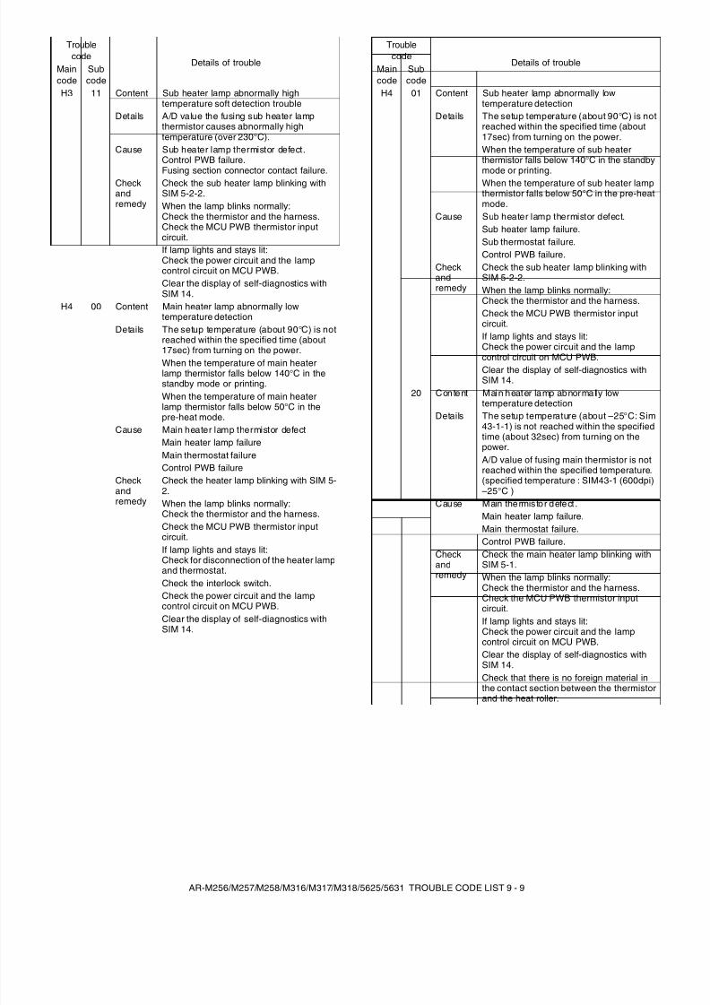
8/9/2019 AR-M318 SM
http://slidepdf.com/reader/full/ar-m318-sm 108/159
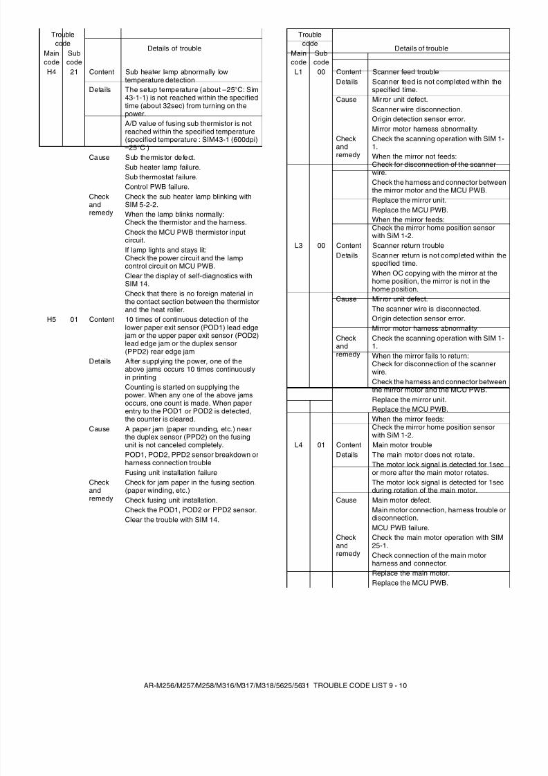
8/9/2019 AR-M318 SM
http://slidepdf.com/reader/full/ar-m318-sm 109/159
AR-M256/M257/M258/M316/M317/M318/5625/5631 TROUBLE CODE LIST 9 - 10
H4 21 Content Sub heater lamp abnormally lowtemperature detection
Details The setup temperature (about –25°C: Sim43-1-1) is not reached within the specifiedtime (about 32sec) from turning on thepower.A/D value of fusing sub thermistor is notreached within the specified temperature(specified temperature : SIM43-1 (600dpi)–25°C )
Cause Sub thermistor defect.Sub heater lamp failure.Sub thermostat failure.Control PWB failure.
Checkandremedy
Check the sub heater lamp blinking withSIM 5-2-2.When the lamp blinks normally:Check the thermistor and the harness.Check the MCU PWB thermistor inputcircuit.If lamp lights and stays lit:Check the power circuit and the lampcontrol circuit on MCU PWB.Clear the display of self-diagnostics withSIM 14.Check that there is no foreign material inthe contact section between the thermistorand the heat roller.
H5 01 Content 10 times of continuous detection of thelower paper exit sensor (POD1) lead edge
jam or the upper paper exit sensor (POD2)lead edge jam or the duplex sensor(PPD2) rear edge jam
Details After supplying the power, one of theabove jams occurs 10 times continuouslyin printingCounting is started on supplying thepower. When any one of the above jamsoccurs, one count is made. When paperentry to the POD1 or POD2 is detected,the counter is cleared.
Cause A paper jam (paper rounding, etc.) nearthe duplex sensor (PPD2) on the fusingunit is not canceled completely.POD1, POD2, PPD2 sensor breakdown orharness connection troubleFusing unit installation failure
Checkandremedy
Check for jam paper in the fusing section.(paper winding, etc.)Check fusing unit installation.Check the POD1, POD2 or PPD2 sensor.Clear the trouble with SIM 14.
Troublecode
Details of troubleMaincode
Subcode
L1 00 Content Scanner feed troubleDetails Scanner feed is not completed within the
specified time.Cause Mir ror unit defect.
Scanner wire disconnection.Origin detection sensor error.Mirror motor harness abnormality.
Checkandremedy
Check the scanning operation with SIM 1-1.When the mirror not feeds:Check for disconnection of the scannerwire.Check the harness and connector betweenthe mirror motor and the MCU PWB.Replace the mirror unit.Replace the MCU PWB.When the mirror feeds:Check the mirror home position sensorwith SiM 1-2.
L3 00 Content Scanner return troubleDetails Scanner return is not completed within the
specified time.
When OC copying with the mirror at thehome position, the mirror is not in thehome position.
Cause Mir ror unit defect.The scanner wire is disconnected.Origin detection sensor error.Mirror motor harness abnormality.
Checkandremedy
Check the scanning operation with SIM 1-1.When the mirror fails to return:Check for disconnection of the scannerwire.Check the harness and connector betweenthe mirror motor and the MCU PWB.Replace the mirror unit.
Replace the MCU PWB.When the mirror feeds:Check the mirror home position sensorwith SiM 1-2.
L4 01 Content Main motor troubleDetails The main motor does not rotate.
The motor lock signal is detected for 1secor more after the main motor rotates.The motor lock signal is detected for 1secduring rotation of the main motor.
Cause Main motor defect.Main motor connection, harness trouble ordisconnection.MCU PWB failure.
Checkandremedy
Check the main motor operation with SIM25-1.Check connection of the main motorharness and connector.Replace the main motor.Replace the MCU PWB.
Troublecode
Details of troubleMaincode
Subcode
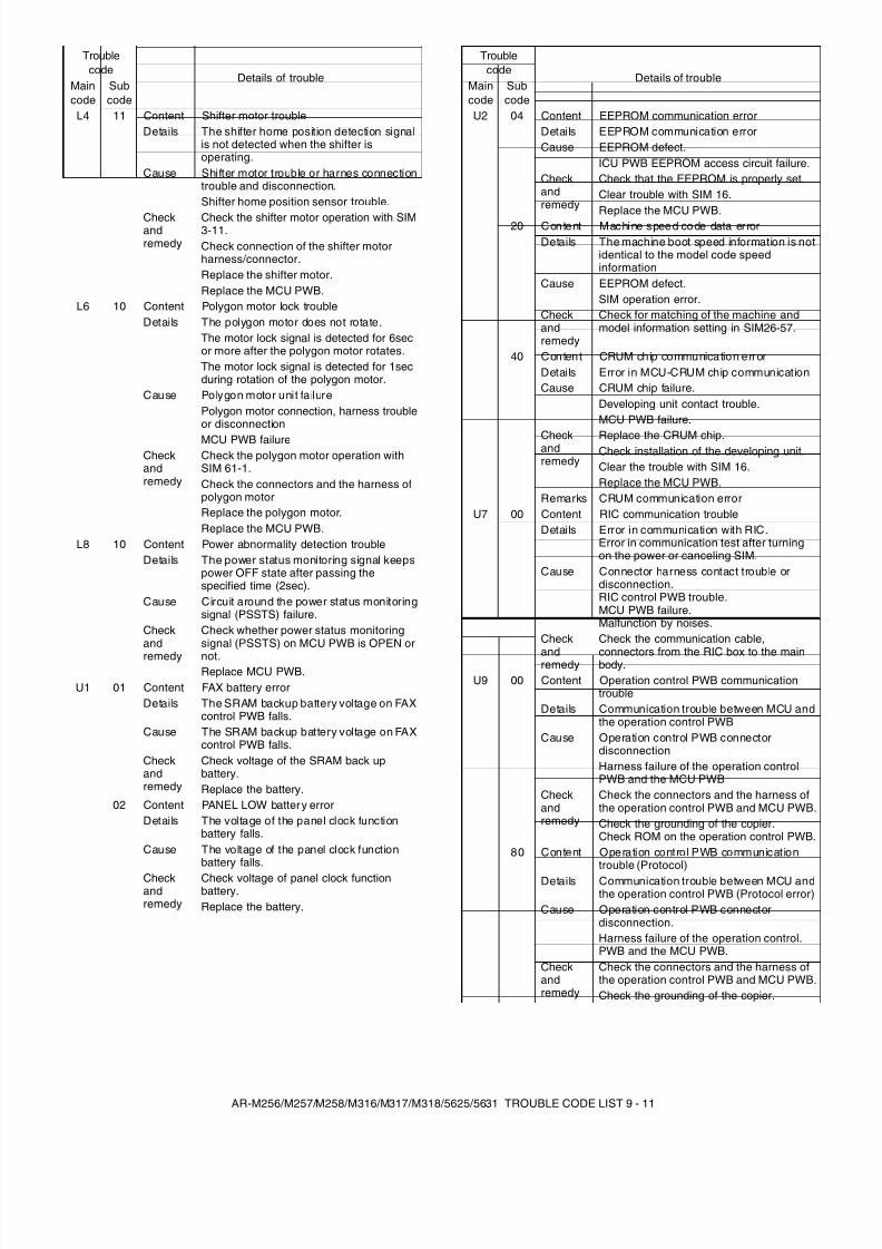
8/9/2019 AR-M318 SM
http://slidepdf.com/reader/full/ar-m318-sm 110/159
AR-M256/M257/M258/M316/M317/M318/5625/5631 TROUBLE CODE LIST 9 - 11
L4 11 Content Shifter motor troubleDetails The shifter home position detection signal
is not detected when the shifter isoperating.
Cause Shifter motor trouble or harnes connectiontrouble and disconnection.Shifter home position sensor trouble.
Checkandremedy
Check the shifter motor operation with SIM3-11.Check connection of the shifter motorharness/connector.Replace the shifter motor.Replace the MCU PWB.
L6 10 Content Polygon motor lock troubleDetails The polygon motor does not rotate.
The motor lock signal is detected for 6secor more after the polygon motor rotates.The motor lock signal is detected for 1secduring rotation of the polygon motor.
Cause Polygon motor unit failurePolygon motor connection, harness troubleor disconnection
MCU PWB failureCheckandremedy
Check the polygon motor operation withSIM 61-1.Check the connectors and the harness ofpolygon motorReplace the polygon motor.Replace the MCU PWB.
L8 10 Content Power abnormality detection troubleDetails The power status monitoring signal keeps
power OFF state after passing thespecified time (2sec).
Cause Circuit around the power status monitoringsignal (PSSTS) failure.
Checkand
remedy
Check whether power status monitoringsignal (PSSTS) on MCU PWB is OPEN or
not.Replace MCU PWB.
U1 01 Content FAX battery errorDetails The SRAM backup battery voltage on FAX
control PWB falls.Cause The SRAM backup battery voltage on FAX
control PWB falls.Checkandremedy
Check voltage of the SRAM back upbattery.Replace the battery.
02 Content PANEL LOW battery errorDetails The voltage of the panel clock function
battery falls.Cause The voltage of the panel clock function
battery falls.
Checkandremedy
Check voltage of panel clock functionbattery.Replace the battery.
Troublecode
Details of troubleMaincode
Subcode
U2 04 Content EEPROM communication errorDetails EEPROM communication errorCause EEPROM defect.
ICU PWB EEPROM access circuit failure.Checkandremedy
Check that the EEPROM is properly set.Clear trouble with SIM 16.Replace the MCU PWB.
20 Content Machine speed code data er rorDetails The machine boot speed information is not
identical to the model code speedinformation
Cause EEPROM defect.SIM operation error.
Checkandremedy
Check for matching of the machine andmodel information setting in SIM26-57.
40 Conten t CRUM chip communication errorDetails Error in MCU-CRUM chip communicationCause CRUM chip failure.
Developing unit contact trouble.MCU PWB failure.
Checkandremedy
Replace the CRUM chip.Check installation of the developing unit.Clear the trouble with SIM 16.Replace the MCU PWB.
Remarks CRUM communication errorU7 00 Content RIC communication trouble
Details Error in communication with RIC.Error in communication test after turningon the power or canceling SIM.
Cause Connector harness contact trouble ordisconnection.RIC control PWB trouble.MCU PWB failure.Malfunction by noises.
Check
andremedy
Check the communication cable,
connectors from the RIC box to the mainbody.U9 00 Content Operation control PWB communication
troubleDetails Communication trouble between MCU and
the operation control PWBCause Operation control PWB connector
disconnectionHarness failure of the operation controlPWB and the MCU PWB
Checkandremedy
Check the connectors and the harness ofthe operation control PWB and MCU PWB.Check the grounding of the copier.Check ROM on the operation control PWB.
80 Content Operation control PWB communicationtrouble (Protocol)
Details Communication trouble between MCU andthe operation control PWB (Protocol error)
Cause Operation control PWB connectordisconnection.Harness failure of the operation control.PWB and the MCU PWB.
Checkandremedy
Check the connectors and the harness ofthe operation control PWB and MCU PWB.Check the grounding of the copier.
Troublecode
Details of troubleMaincode
Subcode
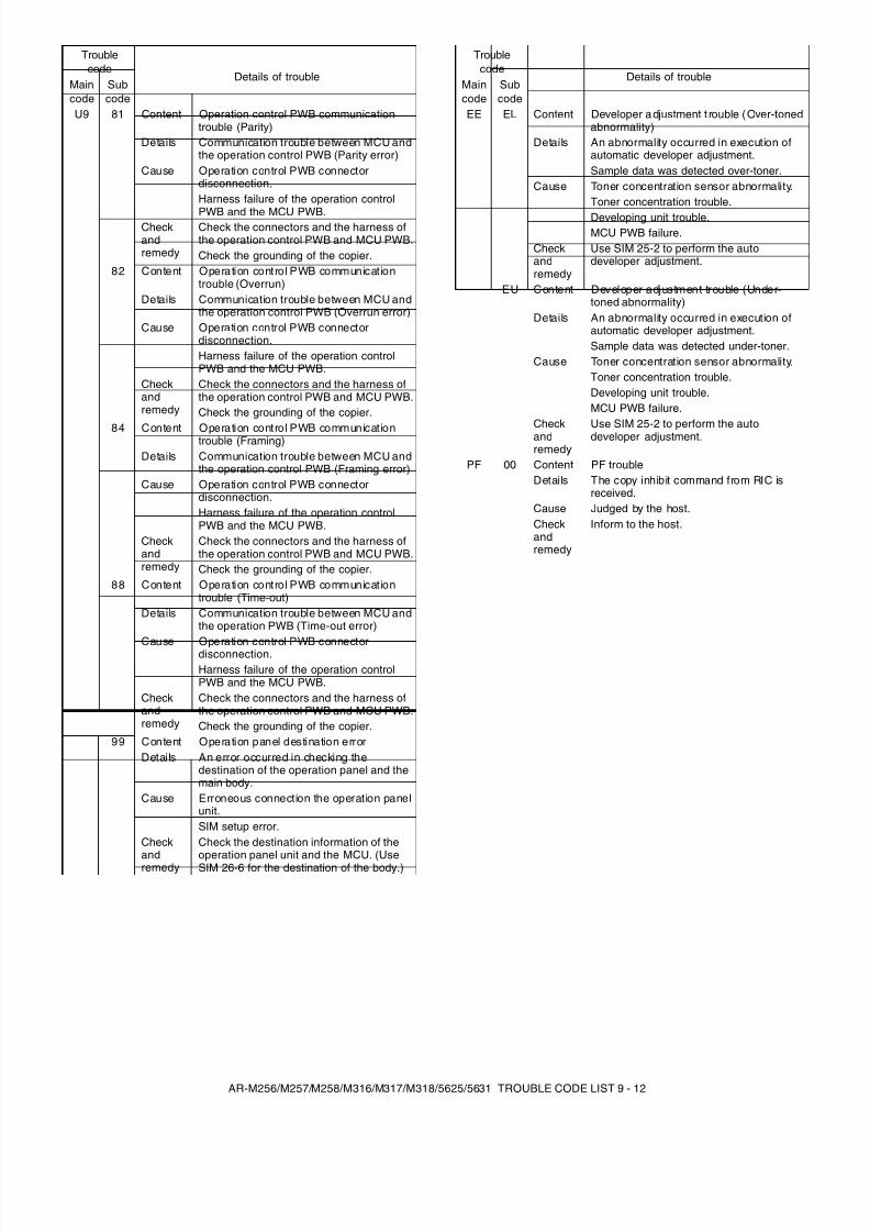
8/9/2019 AR-M318 SM
http://slidepdf.com/reader/full/ar-m318-sm 111/159
AR-M256/M257/M258/M316/M317/M318/5625/5631 TROUBLE CODE LIST 9 - 12
U9 81 Content Operation control PWB communicationtrouble (Parity)
Details Communication trouble between MCU andthe operation control PWB (Parity error)
Cause Operation control PWB connectordisconnection.Harness failure of the operation control
PWB and the MCU PWB.Checkandremedy
Check the connectors and the harness ofthe operation control PWB and MCU PWB.Check the grounding of the copier.
82 Content Operation control PWB communicationtrouble (Overrun)
Details Communication trouble between MCU andthe operation control PWB (Overrun error)
Cause Operation control PWB connectordisconnection.Harness failure of the operation controlPWB and the MCU PWB.
Checkandremedy
Check the connectors and the harness ofthe operation control PWB and MCU PWB.Check the grounding of the copier.
84 Content Operation control PWB communicationtrouble (Framing)Details Communication trouble between MCU and
the operation control PWB (Framing error)Cause Operation control PWB connector
disconnection.Harness failure of the operation controlPWB and the MCU PWB.
Checkandremedy
Check the connectors and the harness ofthe operation control PWB and MCU PWB.Check the grounding of the copier.
88 Content Operation control PWB communicationtrouble (Time-out)
Details Communication trouble between MCU andthe operation PWB (Time-out error)
Cause Operation control PWB connectordisconnection.Harness failure of the operation controlPWB and the MCU PWB.
Checkandremedy
Check the connectors and the harness ofthe operation control PWB and MCU PWB.Check the grounding of the copier.
99 Content Operation panel destination errorDetails An error occurred in checking the
destination of the operation panel and themain body.
Cause Erroneous connection the operation panelunit.SIM setup error.
Checkandremedy
Check the destination information of theoperation panel unit and the MCU. (UseSIM 26-6 for the destination of the body.)
Troublecode
Details of troubleMaincode
Subcode
EE EL Content Developer adjustment t rouble (Over-tonedabnormality)
Details An abnormality occurred in execution ofautomatic developer adjustment.Sample data was detected over-toner.
Cause Toner concentration sensor abnormality.Toner concentration trouble.
Developing unit trouble.MCU PWB failure.
Checkandremedy
Use SIM 25-2 to perform the autodeveloper adjustment.
EU Content Developer adjustment trouble (Under-toned abnormality)
Details An abnormality occurred in execution ofautomatic developer adjustment.Sample data was detected under-toner.
Cause Toner concentration sensor abnormality.Toner concentration trouble.Developing unit trouble.MCU PWB failure.
Checkandremedy
Use SIM 25-2 to perform the autodeveloper adjustment.
PF 00 Content PF troubleDetails The copy inhibit command from RIC is
received.Cause Judged by the host.Checkandremedy
Inform to the host.
Troublecode
Details of troubleMaincode
Subcode

8/9/2019 AR-M318 SM
http://slidepdf.com/reader/full/ar-m318-sm 112/159
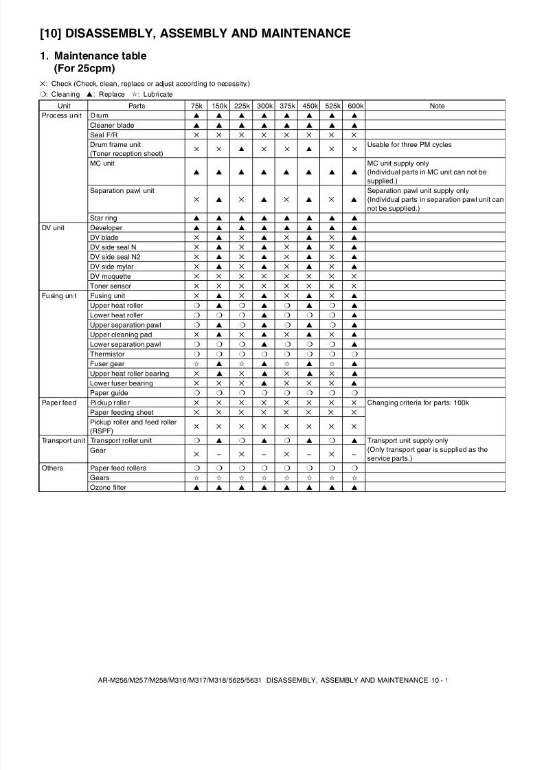
8/9/2019 AR-M318 SM
http://slidepdf.com/reader/full/ar-m318-sm 113/159
AR-M256/M257/M258/M316/M317/M318/5625/5631 DISASSEMBLY, ASSEMBLY AND MAINTENANCE 10 - 1
[10] DISASSEMBLY, ASSEMBLY AND MAINTENANCE
1. Maintenance table(For 25cpm)
: Check (Check, clean, replace or adjust according to necessity.): Cleaning ▲ : Replace : Lubricate
Unit Parts 75k 150k 225k 300k 375k 450k 525k 600k NoteProcess uni t Drum ▲ ▲ ▲ ▲ ▲ ▲ ▲ ▲
Cleaner blade ▲ ▲ ▲ ▲ ▲ ▲ ▲ ▲
Seal F/R
Drum frame unit(Toner reception sheet)
▲ ▲ Usable for three PM cycles
MC unit▲ ▲ ▲ ▲ ▲ ▲ ▲ ▲
MC unit supply only(Individual parts in MC unit can not besupplied.)
Separation pawl unit ▲ ▲ ▲ ▲
Separation pawl unit supply only(Individual parts in separation pawl unit cannot be supplied.)
Star ring ▲ ▲ ▲ ▲ ▲ ▲ ▲ ▲
DV unit Developer ▲ ▲ ▲ ▲ ▲ ▲ ▲ ▲
DV blade ▲ ▲ ▲ ▲
DV side seal N ▲ ▲ ▲ ▲
DV side seal N2 ▲ ▲ ▲ ▲
DV side mylar ▲ ▲ ▲ ▲
DV moquette
Toner sensor
Fu sing unit Fusing unit ▲ ▲ ▲ ▲
Upper heat roller ▲ ▲ ▲ ▲
Lower heat roller ▲ ▲
Upper separation pawl ▲ ▲ ▲ ▲
Upper cleaning pad ▲ ▲ ▲ ▲
Lower separation pawl ▲ ▲
Thermistor
Fuser gear ▲ ▲ ▲ ▲
Upper heat roller bearing ▲ ▲ ▲ ▲
Lower fuser bearing ▲ ▲
Paper guide
Paper feed Pickup roller Changing criteria for parts: 100kPaper feeding sheet
Pickup roller and feed roller(RSPF)
Transport unit Transport roller unit ▲ ▲ ▲ ▲ Transport unit supply only(Only transport gear is supplied as theservice parts.)
Gear – – – –
Others Paper feed rollers
Gears
Ozone filter ▲ ▲ ▲ ▲ ▲ ▲ ▲ ▲
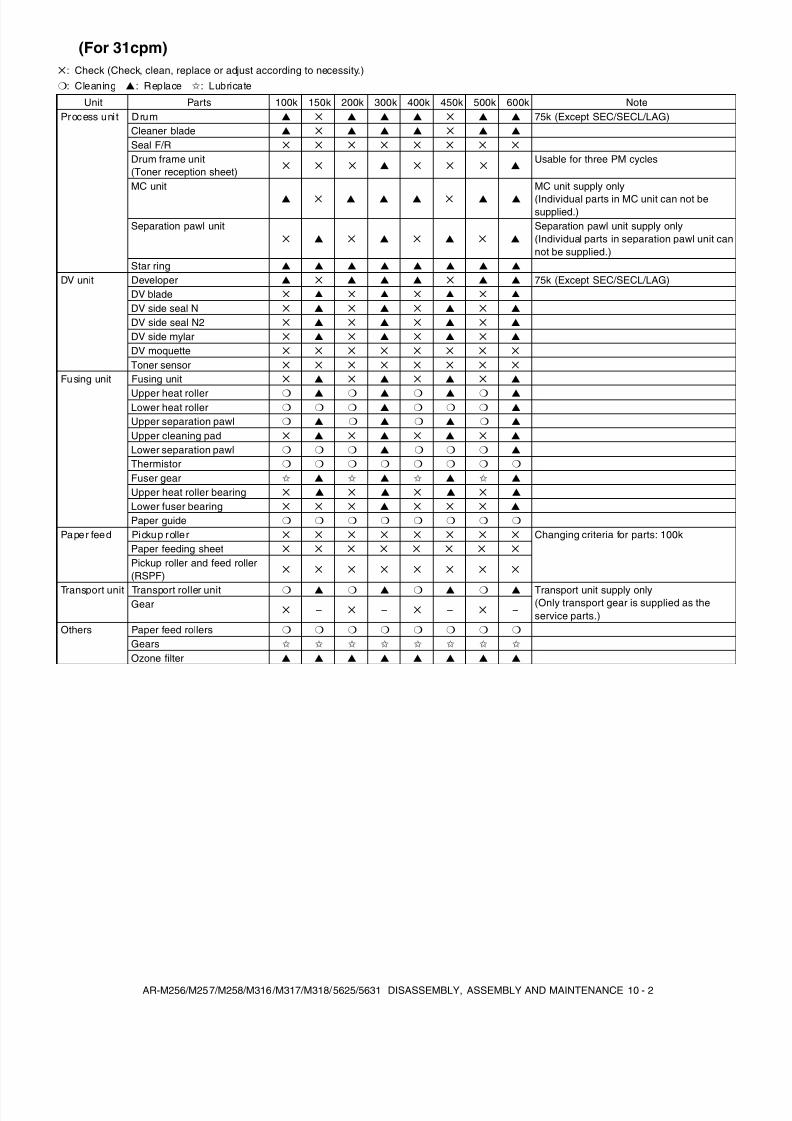
8/9/2019 AR-M318 SM
http://slidepdf.com/reader/full/ar-m318-sm 114/159
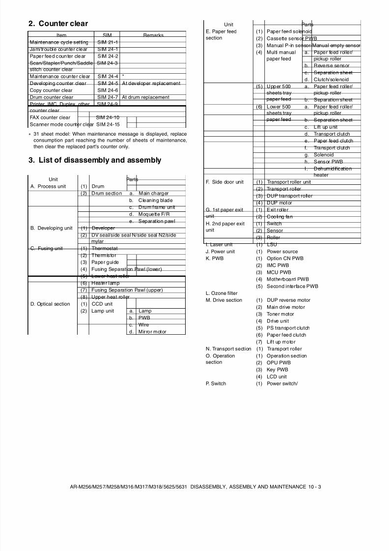
8/9/2019 AR-M318 SM
http://slidepdf.com/reader/full/ar-m318-sm 115/159
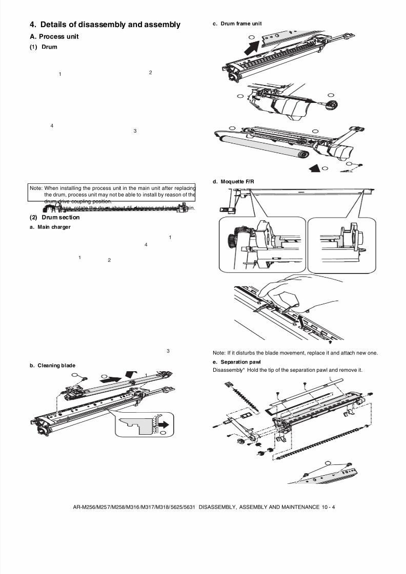
8/9/2019 AR-M318 SM
http://slidepdf.com/reader/full/ar-m318-sm 116/159
AR-M256/M257/M258/M316/M317/M318/5625/5631 DISASSEMBLY, ASSEMBLY AND MAINTENANCE 10 - 4
4. Details of disassembly and assemblyA. Process unit(1) Drum
Note: When installing the process unit in the main unit after replacingthe drum, process unit may not be able to install by reason of the
drum drive coupling position.In this case, rotate the drum about 45 degrees and install again.
(2) Drum section
a. Main charger
b. Cleaning blade
c. Drum frame unit
d. Moquette F/R
Note: If it disturbs the blade movement, replace it and attach new one.
e. Separation pawlDisassembly* Hold the tip of the separation pawl and remove it.
21
43
1 2
4
3
1
1
2
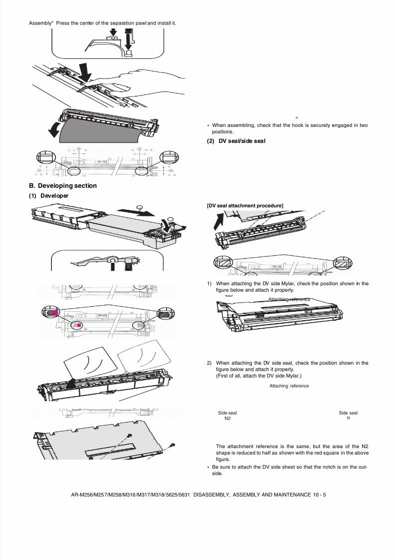
8/9/2019 AR-M318 SM
http://slidepdf.com/reader/full/ar-m318-sm 117/159
AR-M256/M257/M258/M316/M317/M318/5625/5631 DISASSEMBLY, ASSEMBLY AND MAINTENANCE 10 - 5
Assembly* Press the center of the separation pawl and install it.
B. Developing section
(1) Developer
When assembling, check that the hook is securely engaged in twopositions.
(2) DV seal/side seal
[DV seal attachment procedure]
1) When attaching the DV side Mylar, check the position shown in thefigure below and attach it properly.
2) When attaching the DV side seal, check the position shown in thefigure below and attach it properly.(First of all, attach the DV side Mylar.)
The attachment reference is the same, but the area of the N2shape is reduced to half as shown with the red square in the abovefigure.
Be sure to attach the DV side sheet so that the notch is on the out-side.
1
2
Attaching reference
Attaching reference
Side sealN
Side sealN2
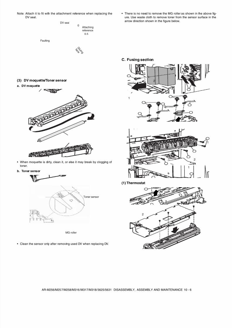
8/9/2019 AR-M318 SM
http://slidepdf.com/reader/full/ar-m318-sm 118/159
AR-M256/M257/M258/M316/M317/M318/5625/5631 DISASSEMBLY, ASSEMBLY AND MAINTENANCE 10 - 6
Note: Attach it to fit with the attachment reference when replacing theDV seal.
(3) DV moquette/Toner sensor
a. DV moquette
• When moquette is dirty, clean it, or else it may break by clogging oftoner.
b. Toner sensor
• Clean the sensor only after removing used DV when replacing DV.
• There is no need to remove the MG roller as shown in the above fig-ure. Use waste cloth to remove toner from the sensor surface in thearrow direction shown in the figure below.
C. Fusing section
(1) Thermostat
DV seal
Faulting
Attachingreference
G l u i n g f a c e
0
0.5
DV moquette
Toner sensor
MG roller
3
3
1
2
1
1
1
2
2
22
3
3
1
1
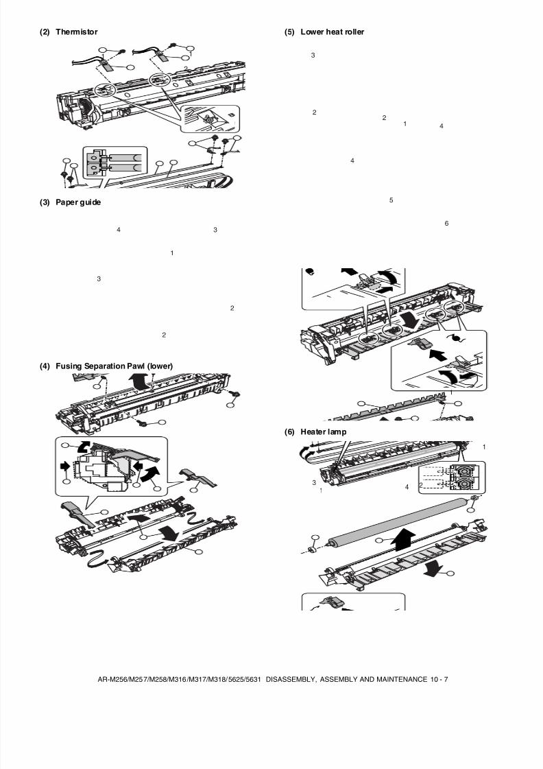
8/9/2019 AR-M318 SM
http://slidepdf.com/reader/full/ar-m318-sm 119/159
AR-M256/M257/M258/M316/M317/M318/5625/5631 DISASSEMBLY, ASSEMBLY AND MAINTENANCE 10 - 7
(2) Thermistor
(3) Paper guide
(4) Fusing Separation Pawl (lower)
(5) Lower heat roller
(6) Heater lamp
2
2
11
2
2
1
3
3
4
12
2
3
4
4
5
6
2
1
3
3
1
12
3
3 4
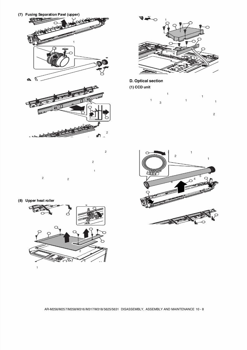
8/9/2019 AR-M318 SM
http://slidepdf.com/reader/full/ar-m318-sm 120/159
AR-M256/M257/M258/M316/M317/M318/5625/5631 DISASSEMBLY, ASSEMBLY AND MAINTENANCE 10 - 8
(7) Fusing Separation Pawl (upper)
(8) Upper heat roller
D. Optical section(1) CCD unit
1
2
1
2
2
2
22
2
1
1
1
1
2
1
2
3
3
11
1
1 1
2
3
44
5
1 1
12
3
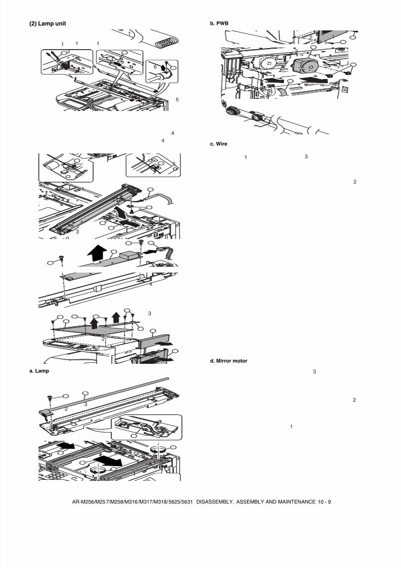
8/9/2019 AR-M318 SM
http://slidepdf.com/reader/full/ar-m318-sm 121/159
AR-M256/M257/M258/M316/M317/M318/5625/5631 DISASSEMBLY, ASSEMBLY AND MAINTENANCE 10 - 9
(2) Lamp unit
a. Lamp
b. PWB
c. Wire
d. Mirror motor
4
6
5
4
1
1 1 1
2
3
1
1
2
2
33
4
12
3
1
23
1
2
2
3
1
2
3
1
3
2
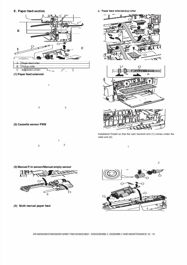
8/9/2019 AR-M318 SM
http://slidepdf.com/reader/full/ar-m318-sm 122/159
AR-M256/M257/M258/M316/M317/M318/5625/5631 DISASSEMBLY, ASSEMBLY AND MAINTENANCE 10 - 10
E. Paper feed section
(1) Paper feed solenoid
(2) Cassette sensor PWB
(3) Manual P-in sensor/Manual empty sensor
(4) Multi manual paper feed
a. Paper feed roller/pickup roller
Installation*Install so that the cam transmit arm (1) comes under theroller arm (2).
A Paper feed ro llerB Pickup rollerC Separation sheet
A
C
B
1
32
3
1
2
A
B
5
6
1 2
43
1
2
2
14
3
L OC K
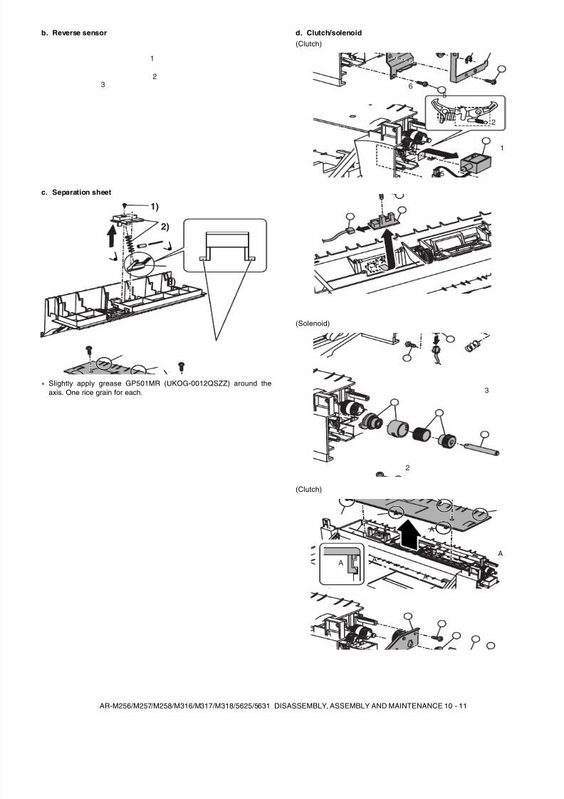
8/9/2019 AR-M318 SM
http://slidepdf.com/reader/full/ar-m318-sm 123/159
AR-M256/M257/M258/M316/M317/M318/5625/5631 DISASSEMBLY, ASSEMBLY AND MAINTENANCE 10 - 11
b. Reverse sensor
c. Separation sheet
Slightly apply grease GP501MR (UKOG-0012QSZZ) around theaxis. One rice grain for each.
d. Clutch/solenoid(Clutch)
(Solenoid)
(Clutch)
1
32
1)
2)
3)
4
5
56
3
1
2
1
2
2
3
1
2
A
A
A A
A
A
A
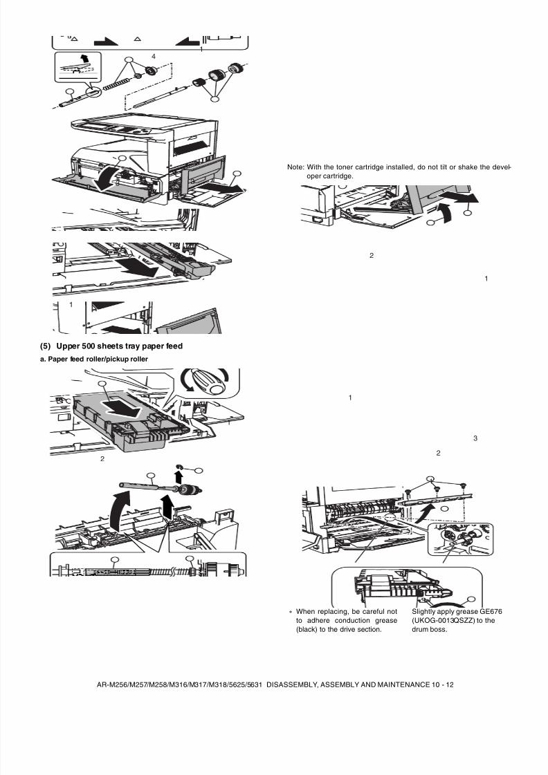
8/9/2019 AR-M318 SM
http://slidepdf.com/reader/full/ar-m318-sm 124/159
AR-M256/M257/M258/M316/M317/M318/5625/5631 DISASSEMBLY, ASSEMBLY AND MAINTENANCE 10 - 12
(5) Upper 500 sheets tray paper feed
a. Paper feed roller/pickup roller
Note: With the toner cartridge installed, do not tilt or shake the devel-oper cartridge.
41
23
3
1
2
1
2
When replacing, be careful notto adhere conduction grease(black) to the drive section.
Slightly apply grease GE676(UKOG-0013QSZZ) to thedrum boss.
2
1
3
1
2
1
2
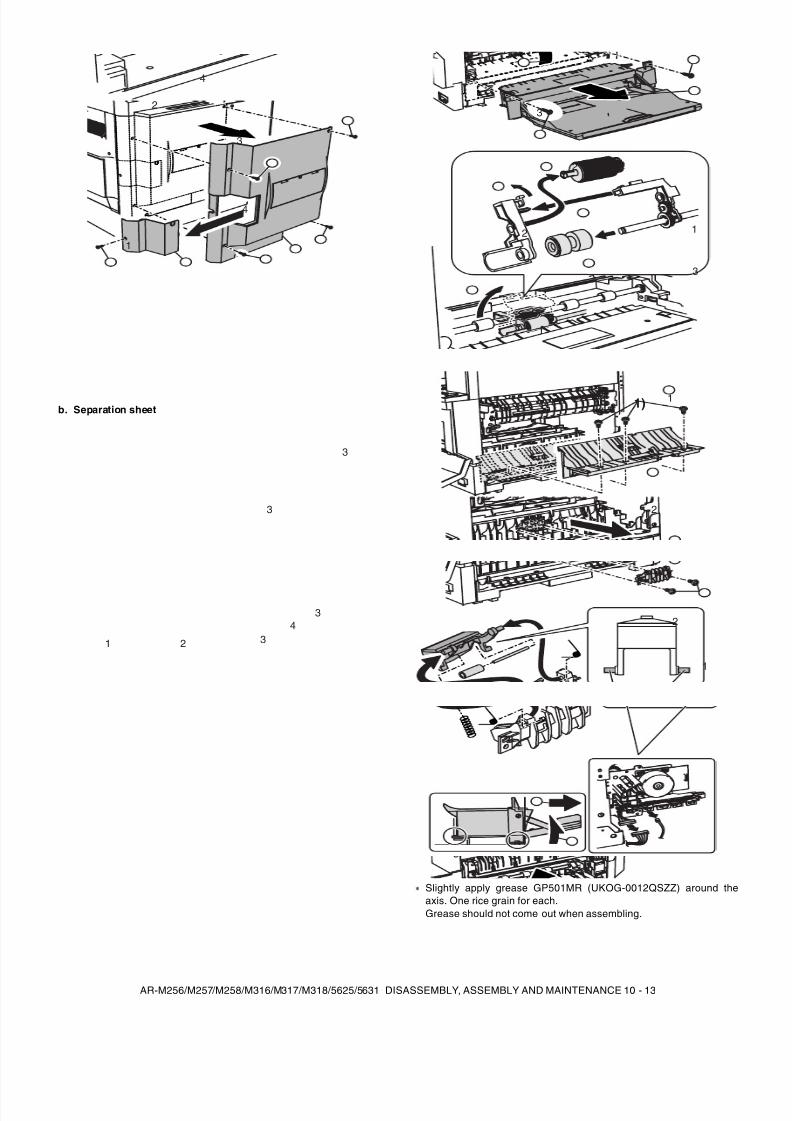
8/9/2019 AR-M318 SM
http://slidepdf.com/reader/full/ar-m318-sm 125/159
AR-M256/M257/M258/M316/M317/M318/5625/5631 DISASSEMBLY, ASSEMBLY AND MAINTENANCE 10 - 13
b. Separation sheet
Slightly apply grease GP501MR (UKOG-0012QSZZ) around theaxis. One rice grain for each.Grease should not come out when assembling.
1
2
4
3
4
1 2
34
3
3
3
1
1
2
2
3
3
1) 1
2
2
1
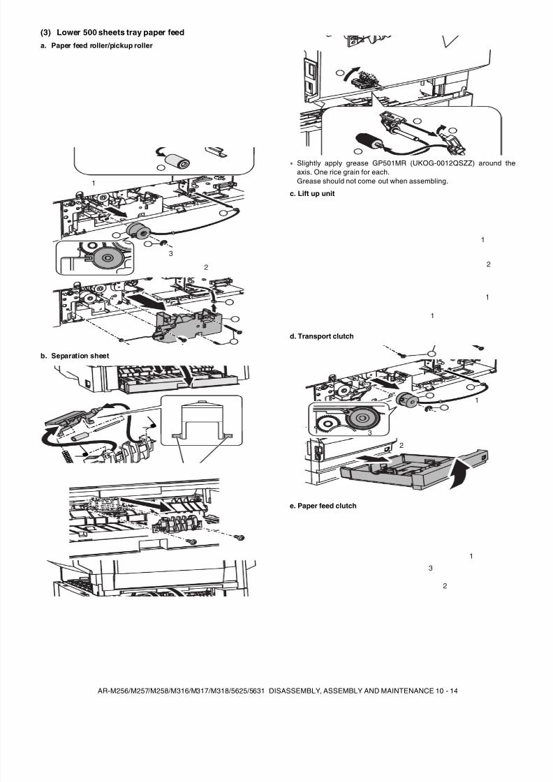
8/9/2019 AR-M318 SM
http://slidepdf.com/reader/full/ar-m318-sm 126/159
AR-M256/M257/M258/M316/M317/M318/5625/5631 DISASSEMBLY, ASSEMBLY AND MAINTENANCE 10 - 14
(3) Lower 500 sheets tray paper feed
a. Paper feed roller/pickup roller
b. Separation sheet
Slightly apply grease GP501MR (UKOG-0012QSZZ) around theaxis. One rice grain for each.Grease should not come out when assembling.
c. Lift up unit
d. Transport clutch
e. Paper feed clutch
1
3
2
4
4
1
2
1
1
1
2
3
2
1
3
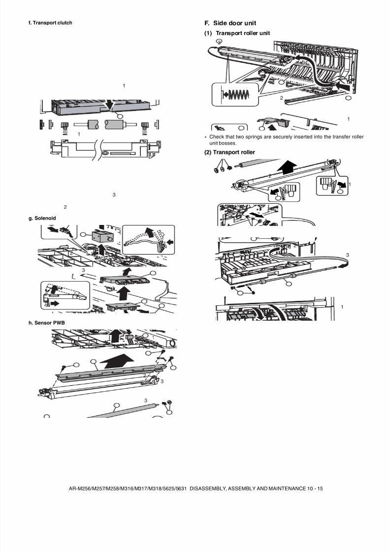
8/9/2019 AR-M318 SM
http://slidepdf.com/reader/full/ar-m318-sm 127/159
AR-M256/M257/M258/M316/M317/M318/5625/5631 DISASSEMBLY, ASSEMBLY AND MAINTENANCE 10 - 15
f. Transport clutch
g. Solenoid
h. Sensor PWB
F. Side door unit(1) Transport roller unit
Check that two springs are securely inserted into the transfer rollerunit bosses.
(2) Transport roller
1
3
2
1
12
3
1
23
3
1
2
3
1
1
12
1
1
2
33
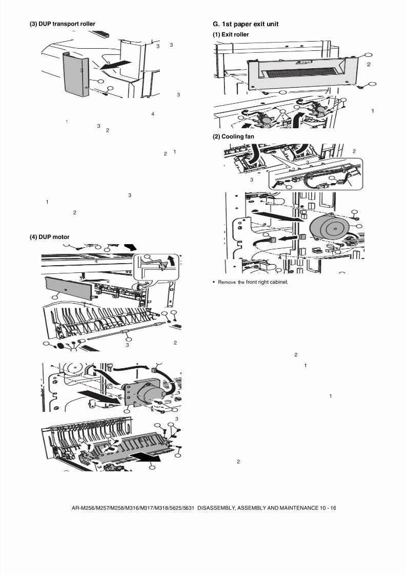
8/9/2019 AR-M318 SM
http://slidepdf.com/reader/full/ar-m318-sm 128/159
AR-M256/M257/M258/M316/M317/M318/5625/5631 DISASSEMBLY, ASSEMBLY AND MAINTENANCE 10 - 16
(3) DUP transport roller
(4) DUP motor
G. 1st paper exit unit(1) Exit roller
(2) Cooling fan
• Remove the front right cabinet .
4
2
33
3
3
3
3
1
1
1
3
2
2
1
23
4
1
2
3
2
1
1
2
1
3
3
2
2
1
2
1
1
2
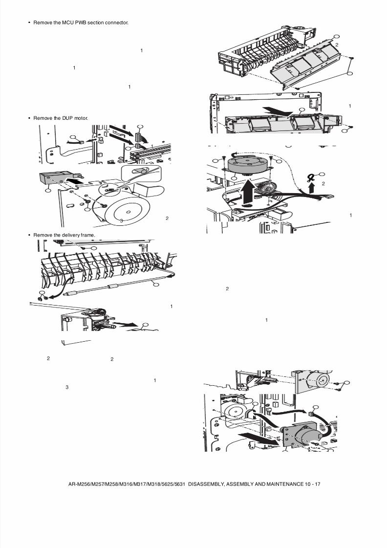
8/9/2019 AR-M318 SM
http://slidepdf.com/reader/full/ar-m318-sm 129/159
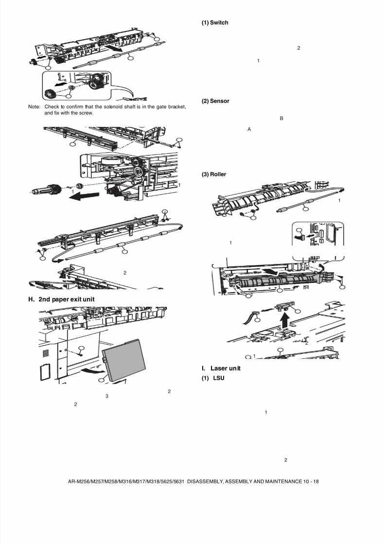
8/9/2019 AR-M318 SM
http://slidepdf.com/reader/full/ar-m318-sm 130/159
AR-M256/M257/M258/M316/M317/M318/5625/5631 DISASSEMBLY, ASSEMBLY AND MAINTENANCE 10 - 18
Note: Check to confirm that the solenoid shaft is in the gate bracket,and fix with the screw.
H. 2nd paper exit unit
(1) Switch
(2) Sensor
(3) Roller
I. Laser unit(1) LSU
1
1
1
2
1
2
1
3
2
1
2
B
A
1
1
2
1
1
2
2
1
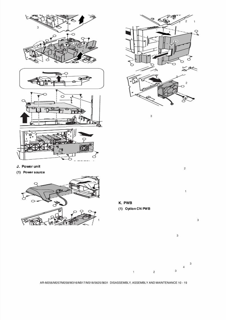
8/9/2019 AR-M318 SM
http://slidepdf.com/reader/full/ar-m318-sm 131/159
AR-M256/M257/M258/M316/M317/M318/5625/5631 DISASSEMBLY, ASSEMBLY AND MAINTENANCE 10 - 19
J. Power unit(1) Power source
K. PWB(1) Option CN PWB
1
21
3
1
22
3
1
1
2
1 2 1
11
1
2
3
2
2
2
2
2
1
1 2
34
3
3
3
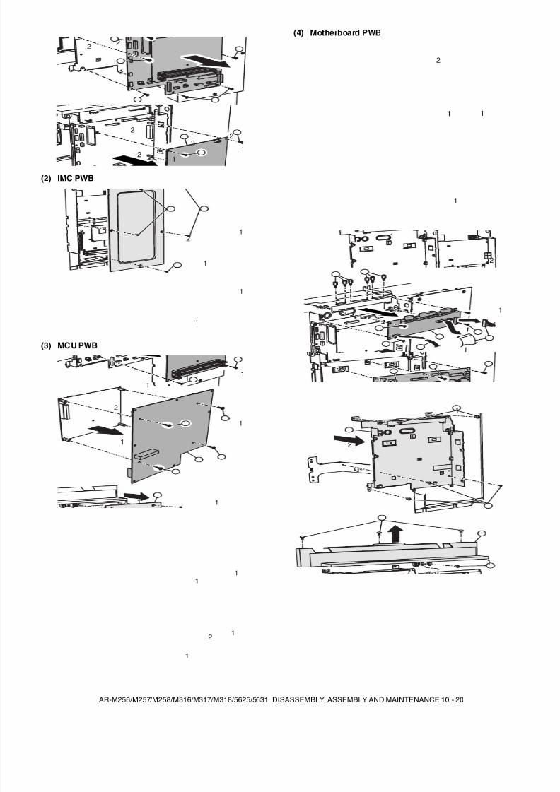
8/9/2019 AR-M318 SM
http://slidepdf.com/reader/full/ar-m318-sm 132/159
AR-M256/M257/M258/M316/M317/M318/5625/5631 DISASSEMBLY, ASSEMBLY AND MAINTENANCE 10 - 20
(2) IMC PWB
(3) MCU PWB
(4) Motherboard PWB
2
2 2
3
1
12
2
21
1
1
1
11
1
1
2
1 1
1
1
12
1
1
1
1 1
2
1
2
1
1
1
2
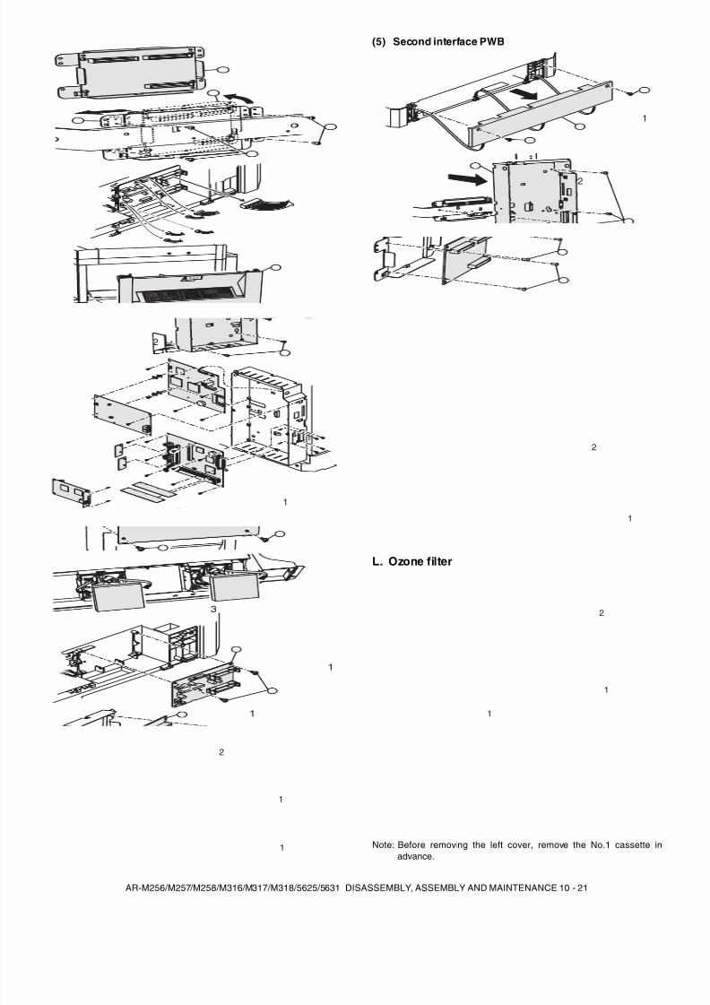
8/9/2019 AR-M318 SM
http://slidepdf.com/reader/full/ar-m318-sm 133/159
AR-M256/M257/M258/M316/M317/M318/5625/5631 DISASSEMBLY, ASSEMBLY AND MAINTENANCE 10 - 21
(5) Second interface PWB
L. Ozone filter
Note: Before removing the left cover, remove the No.1 cassette inadvance.
1
1
2
4
3
2
1
1
1
1
2
2
1
1
1
2
1
1
2
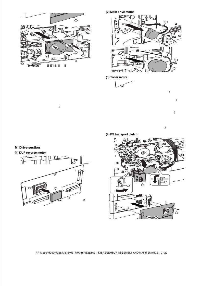
8/9/2019 AR-M318 SM
http://slidepdf.com/reader/full/ar-m318-sm 134/159
AR-M256/M257/M258/M316/M317/M318/5625/5631 DISASSEMBLY, ASSEMBLY AND MAINTENANCE 10 - 22
M. Drive section(1) DUP reverse motor
(2) Main drive motor
(3) Toner motor
(4) PS transport clutch
1
2
1
1
1
1
32
2
13
1
2
2
3
1
1
2
3
4
1
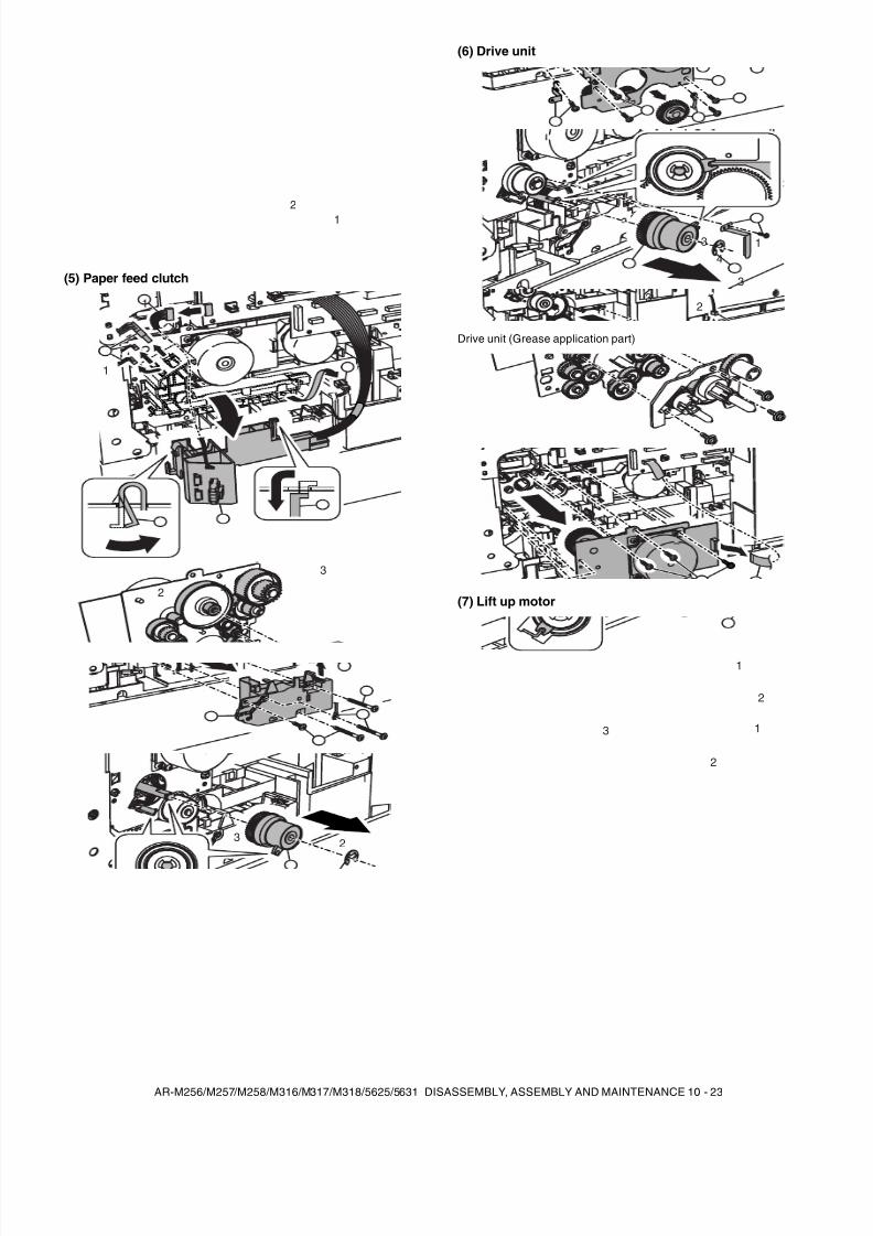
8/9/2019 AR-M318 SM
http://slidepdf.com/reader/full/ar-m318-sm 135/159
AR-M256/M257/M258/M316/M317/M318/5625/5631 DISASSEMBLY, ASSEMBLY AND MAINTENANCE 10 - 23
(5) Paper feed clutch
(6) Drive unit
Drive unit (Grease application part)
(7) Lift up motor
21
1
1
2
3
4
1
1
23
1
3
4
23
3
2
2
1
2
3
1
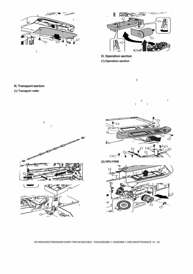
8/9/2019 AR-M318 SM
http://slidepdf.com/reader/full/ar-m318-sm 136/159
AR-M256/M257/M258/M316/M317/M318/5625/5631 DISASSEMBLY, ASSEMBLY AND MAINTENANCE 10 - 24
N. Transport section(1) Transport roller
O. Operation section(1) Operation section
(2) OPU PWB
1
1
2
3
2
1
21
1
13
2
111
2
3
1
1
1
2
1
1
1
3
2
2
2
22
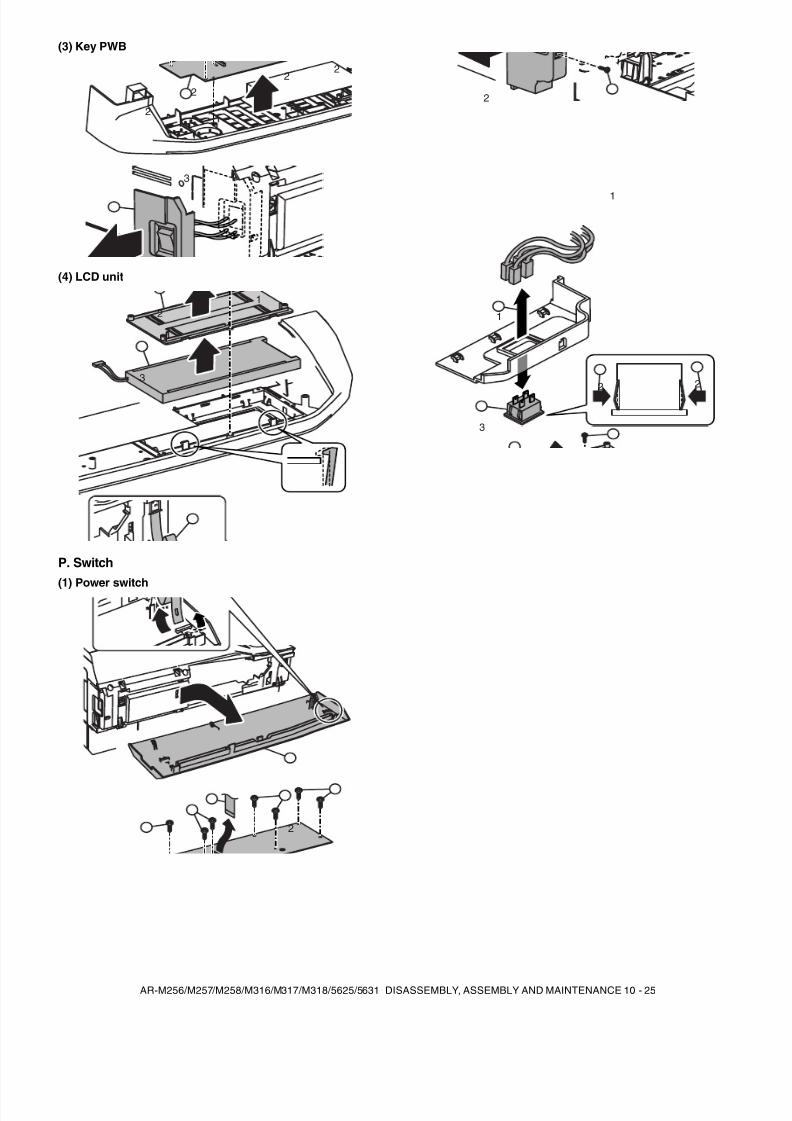
8/9/2019 AR-M318 SM
http://slidepdf.com/reader/full/ar-m318-sm 137/159

8/9/2019 AR-M318 SM
http://slidepdf.com/reader/full/ar-m318-sm 138/159
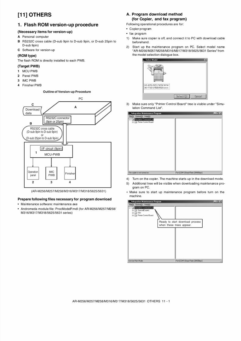
8/9/2019 AR-M318 SM
http://slidepdf.com/reader/full/ar-m318-sm 139/159
AR-M256/M257/M258/M316/M317/M318/5625/5631 OTHERS 11 - 1
[11] OTHERS
1. Flash ROM version-up procedure(Necessary items for version-up)A Personal computerB RS232C cross cable (D-sub 9pin to D-sub 9pin, or D-sub 25pin to
D-sub 9pin)C Software for version-up
(ROM type)The flash ROM is directly installed to each PWB.
(Target PWB)1 MCU PWB2 Panel PWB3 IMC PWB4 Finisher PWB
Prepare following files necessary for program download• Maintenance software: maintenance.exe• Andromeda module file: ProcModelP.mdl (for AR-M256/M257/M258/
M316/M317/M318/5625/5631 series)
A. Program download method(for Copier, and fax program)
Following operational procedures are for:• Copier program• fax program1) Make sure copier is off, and connect it to PC with download cable
beforehand.2) Start up the maintenance program on PC. Select model name
"AR-M256/M257/M258/M316/M317/M318/5625/5631 Series" fromthe model selection dialogue box.
3) Make sure only "Printer Control Board" tree is visible under "Simu-lation Command List".
4) Turn on the copier. The machine starts up in the download mode.5) Additional tree will be visible when downloading maintenance pro-
gram on PC.Make sure to start up maintenance program before turn on themachine.
Outline of Version-up Procedure
PC
(AR-M256/M257/M258/M316/M317/M318/5625/5631)
MCU-PWB
IMCPWB
AC
B
1
2 3 4
RS232C cross cable(D-sub 9pin to D-sub 9pin)
or(D-sub 25pin to D-sub 9pin)
Downloaddata
RS232C connector(9pin or 25pin)
I/F circuit (9pin)
Operationpanel Finisher
Ready to start download processwhen these trees appear.
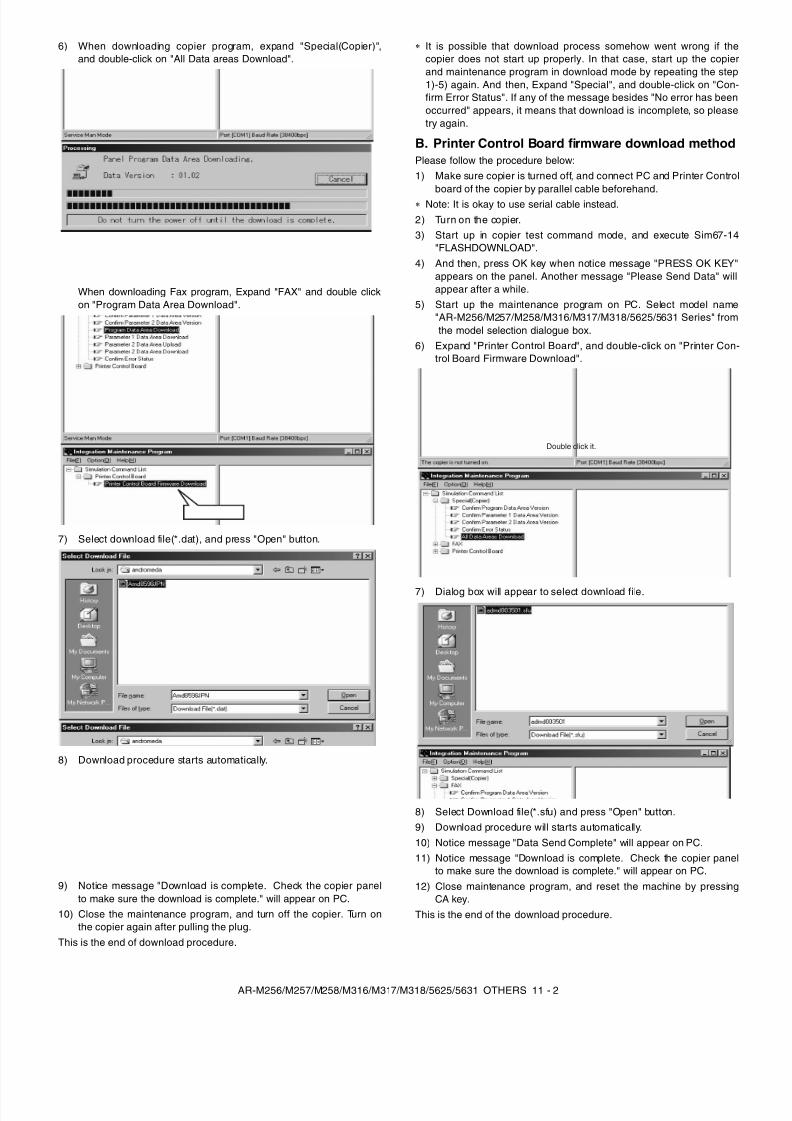
8/9/2019 AR-M318 SM
http://slidepdf.com/reader/full/ar-m318-sm 140/159
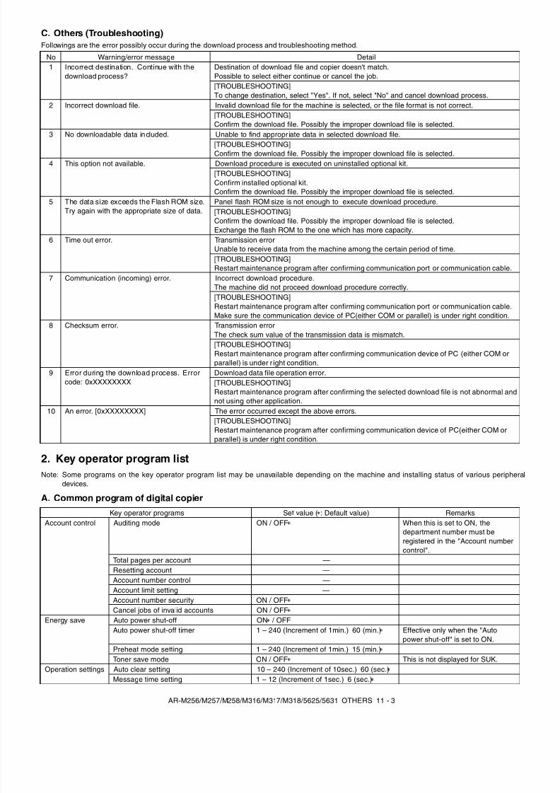
8/9/2019 AR-M318 SM
http://slidepdf.com/reader/full/ar-m318-sm 141/159
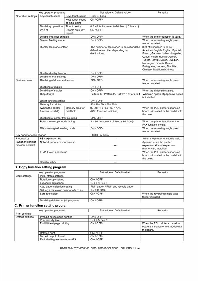
8/9/2019 AR-M318 SM
http://slidepdf.com/reader/full/ar-m318-sm 142/159
AR-M256/M257/M258/M316/M317/M318/5625/5631 OTHERS 11 - 4
B. Copy function setting program
C. Printer function setting program
Operation settings Keys touch sound Keys touch sound Shor t / LongKeys touch soundat initial point
ON / OFF
Touch key operat ionsetting
Time to en try 0 .0 – 2 .0 (Increment o f 0.5sec.) 0 .0 (sec. )Disable auto keyrepeat
ON / OFF
Disable interrupt print job ON / OFF When the printer function is valid.Stream feeding mode ON / OFF When the reversing single pass
feeder installed.Display language setting The number of languages to be set and the
default value differ depending ondestinations.
[List of languages to be set]American English, English, Spanish,French, German, Italian, Hungarian,Czech, Polish, Russian, Greek,Turkish, Slovak, Dutch, Swedish,Norwegian, Finnish, Danish,Portuguese, Hebrew, SimplifiedChinese, Traditional Chinese
Disable display timeout ON / OFFDisable of tray settings ON / OFF
Device control Disabling of document feeder ON / OFF When the reversing single passfeeder installed.
Disabling of duplex ON / OFFDisabling of stapler ON / OFF When the finisher installed.Output trays Pattern 1 / Pattern 2 / Pattern 3 / Pattern 4 When an option of paper exit series
is installed.Offset function setting ON / OFFMemory for printer 30 / 40 / 50 / 60 / 70%(When the printerfunction is valid.)
Memory area forprint hold
0 / 30 / 40 / 50 / 60 / 70%(0%: Function inhibited)
When the PCL printer expansionboard is installed or the model withthe board.
Disabling of center tray counting ON / OFFRetur n from copy mode timing 1 – 60 (Increment of 1sec.) 60 (sec.) When the printer function or the
FAX function is valid.MIX size original feeding mode ON / OFF When the reversing single pass
feeder installed.Key operator code change 00000 (5 digits)Product key(When the printerfunction is valid.)
PS3 expansion kit — When the printer function is valid.Network scanner expansion kit
—Appears when the printerexpansion kit and expansionmemory are installed.
E-MAIL alert and status—
When the PCL printer expansionboard is installed or the model withthe board.
Serial number —
Key operator programs Set value ( : Default value) Remarks
Key operator programs Set value ( : Default value) RemarksCopy settings Initial status settings —
Rotation copy setting ON / OFFExposure adjustment 1 / 2 / 3 / 4 / 5Auto paper selection setting Plain paper / Plain and recycle paperSett ing a maximum number o f cop ies 1 – 999 999Sort auto select ON / OFF When the reversing single pass
feeder installed.Disabling deletion of job programs ON / OFF
Key operator programs Set value ( : Default value) RemarksPrint settingsDefault settings Prohibit notice page printing ON / OFF
Print density level 1 / 2 / 3 / 4 / 5Prohibit test page printing ON / OFF When the PCL printer expansion
board is installed or the model withthe board.
Rotated print ON / OFFForced output of print ON / OFFExcluded bypass-tray from ATS ON / OFF
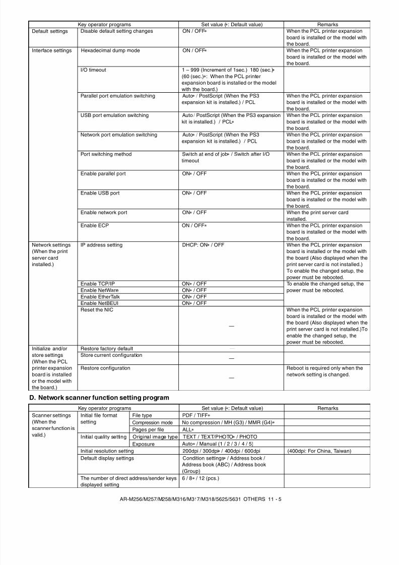
8/9/2019 AR-M318 SM
http://slidepdf.com/reader/full/ar-m318-sm 143/159
AR-M256/M257/M258/M316/M317/M318/5625/5631 OTHERS 11 - 5
D. Network scanner function setting program
Default settings Disable default setting changes ON / OFF When the PCL printer expansionboard is installed or the model withthe board.
Interface settings Hexadecimal dump mode ON / OFF When the PCL printer expansionboard is installed or the model withthe board.
I/O timeout 1 – 999 (Increment of 1sec.) 180 (sec.)(60 (sec.) : When the PCL printerexpansion board is installed or the modelwith the board.)
Parallel port emulation switching Auto / PostScript (When the PS3expansion kit is installed.) / PCL
When the PCL printer expansionboard is installed or the model withthe board.
USB port emulation switching Auto / PostScript (When the PS3 expansionkit is installed.) / PCL
When the PCL printer expansionboard is installed or the model withthe board.
Network port emulation switching Auto / PostScript (When the PS3expansion kit is installed.) / PCL
When the PCL printer expansionboard is installed or the model withthe board.
Port switching method Switch at end of job / Switch after I/Otimeout
When the PCL printer expansionboard is installed or the model withthe board.
Enable parallel port ON / OFF When the PCL printer expansionboard is installed or the model withthe board.
Enable USB port ON / OFF When the PCL printer expansionboard is installed or the model withthe board.
Enable network port ON / OFF When the print server cardinstalled.
Enable ECP ON / OFF When the PCL printer expansionboard is installed or the model withthe board.
Network settings(When the printserver cardinstalled.)
IP address setting DHCP: ON / OFF When the PCL printer expansionboard is installed or the model withthe board (Also displayed when theprint server card is not installed.)To enable the changed setup, thepower must be rebooted.
Enable TCP/IP ON / OFF To enable the changed setup, thepower must be rebooted.Enable NetWare ON / OFF
Enable EtherTalk ON / OFFEnable NetBEUI ON / OFFReset the NIC
—
When the PCL printer expansionboard is installed or the model withthe board (Also displayed when theprint server card is not installed.)Toenable the changed setup, thepower must be rebooted.
Initialize and/orstore settings(When the PCLprinter expansionboard is installedor the model withthe board.)
Restore factory default —Store current configuration —
Restore configuration
—
Reboot is required only when thenetwork setting is changed.
Key operator programs Set value ( : Default value) Remarks
Key operator programs Set value ( : Default value) RemarksScanner settings(When thescanner function isvalid.)
Initial file formatsetting
File type PDF / TIFFCompression mode No compression / MH (G3) / MMR (G4)Pages per file ALL
Initial quality setting Original image type TEXT / TEXT/PHOTO / PHOTOExposure Auto / Manual (1 / 2 / 3 / 4 / 5)
Initial resolution setting 200dpi / 300dpi / 400dpi / 600dpi (400dpi: For China, Taiwan)Default display settings Condition settings / Address book /
Address book (ABC) / Address book(Group)
The number of direct address/sender keysdisplayed setting
6 / 8 / 12 (pcs.)
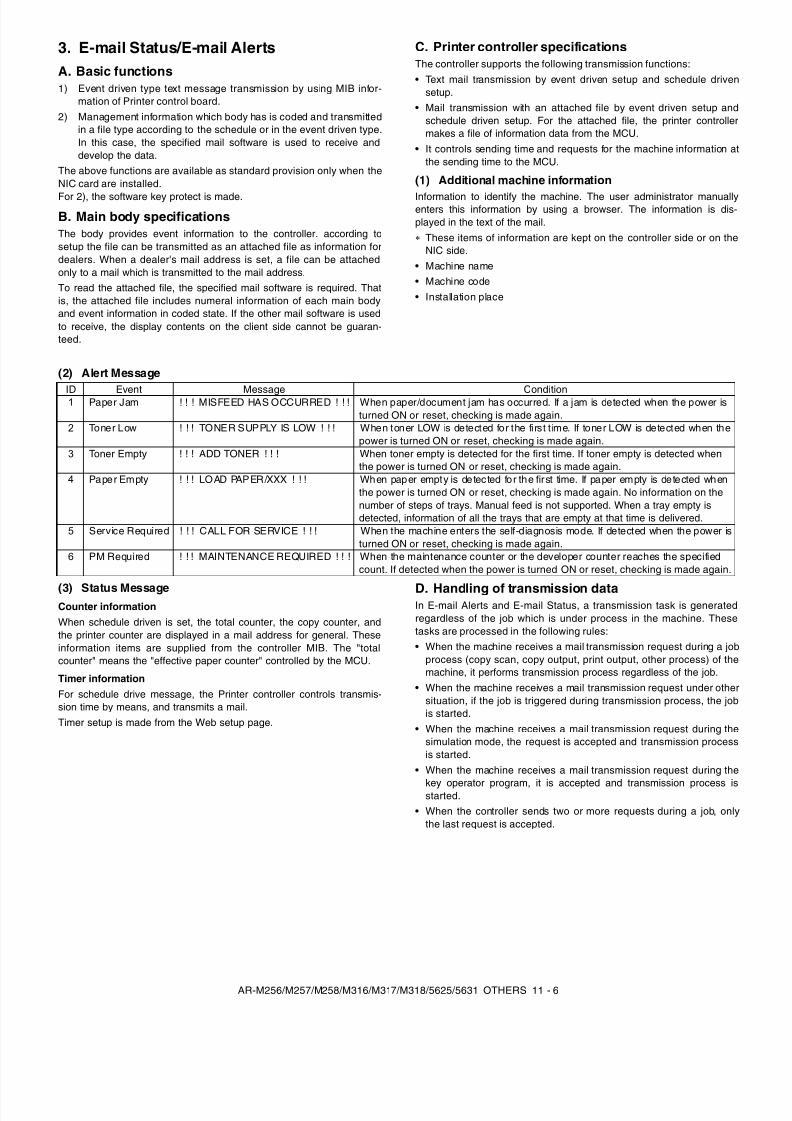
8/9/2019 AR-M318 SM
http://slidepdf.com/reader/full/ar-m318-sm 144/159
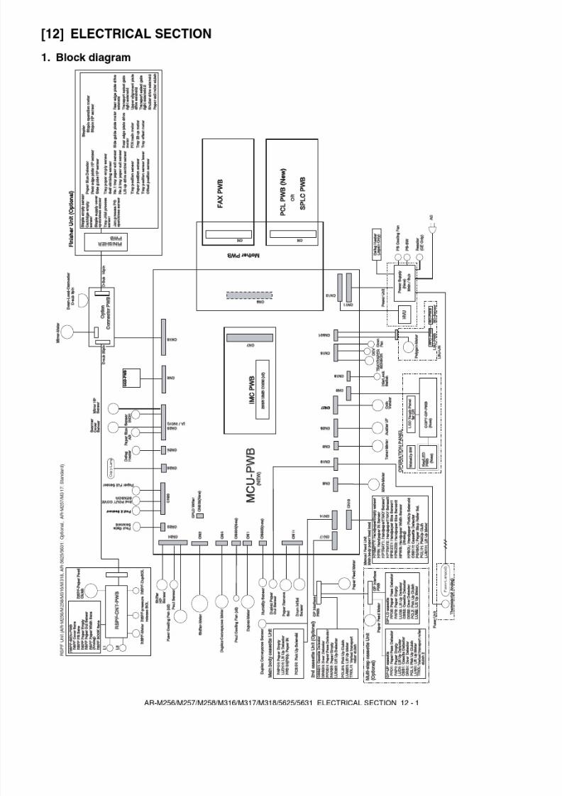
8/9/2019 AR-M318 SM
http://slidepdf.com/reader/full/ar-m318-sm 145/159
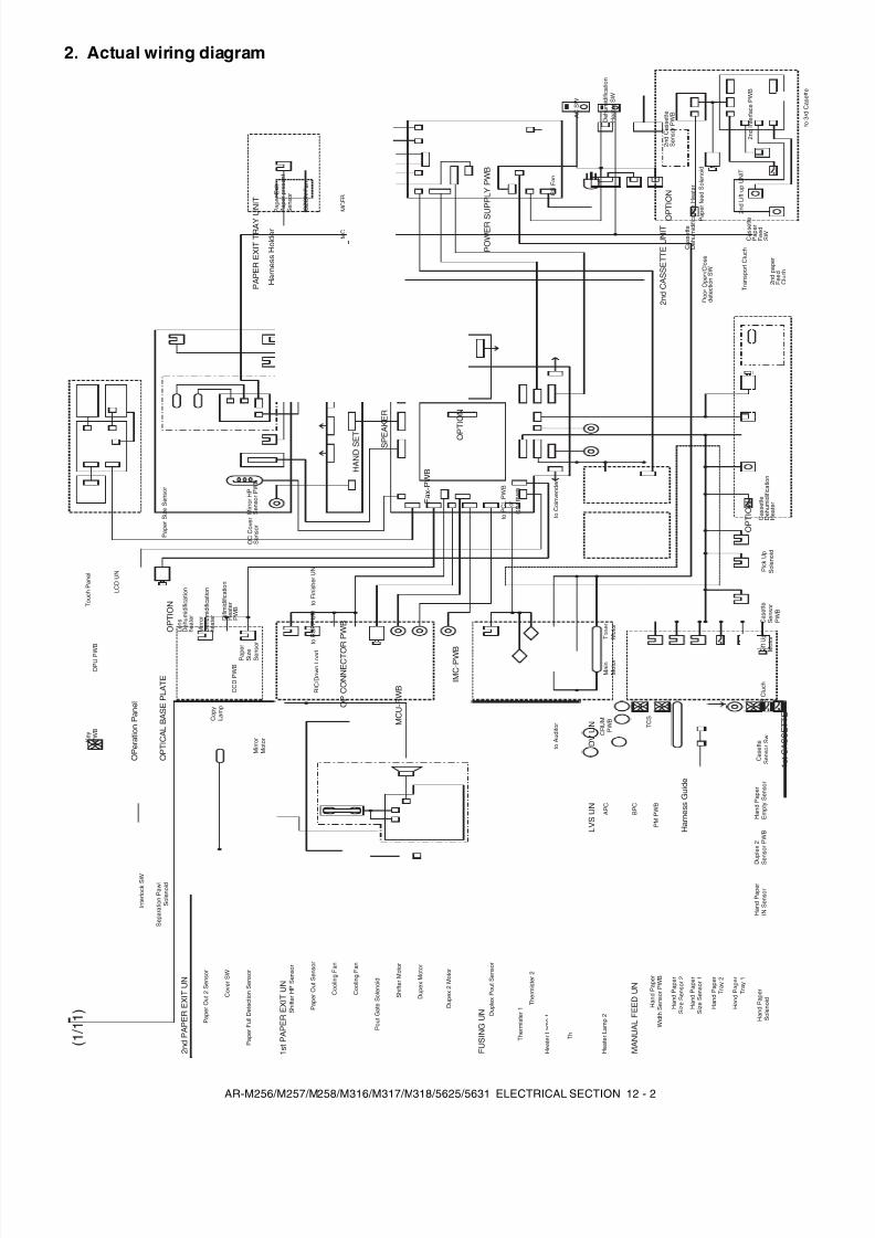
8/9/2019 AR-M318 SM
http://slidepdf.com/reader/full/ar-m318-sm 146/159
AR-M256/M257/M258/M316/M317/M318/5625/5631 ELECTRICAL SECTION 12 - 2
2. Actual wiring diagram
2 n d L i f t - u p U N I T
D u p l e x
P o u t S e n s o r
T h e r m i s t e r 1
H e a t e r L a m p
1
T h e r m i s t e r 2
H e a t e r L a m p
2
F U S I N G U N
L i f t U p
M
o t o r
P S C l u c h
C a s e t t e
S e n s o r S w
C a s e t t e
S e n s o r
P W B
1 s t C A S S E T T E
P i c k U p
S o l e n o i d
H a n d
P a p e r
I N S e n s o r
H a n d
P a p e r
E m p t y
S e n s o r
H a r n e s s
G u i d e
C a s s e t t e
D e h u m
i d i f i c a t i o n
H e a t e r
S h i f t e r H P S e n s o r
P a p e r O u t S e n s o r
C o o l i n g
F a n
C o o l i n g
F a n
P o u t G a t e
S o l e n o i d
S h i f t e r M o t o r
D u p e x
2 M o t o r
D u p e x
M o t o r
1 s t P A P E R E X I T U N
I n t e r l o c k S W
S e p a r a t i o n
P a w
l
S o l e n o i d
H a n d
P a p e r
S o l e n o i d
H a n d
P a p e r
T r a y 1
H a n d
P a p e r
T r a y 2
H a n d
P a p e r
S i z e S e n s o r 1
H a n d
P a p e r
S i z e S e n s o r 2
H a n d
P a p e r
W i d t h S e n s o r P
W B
M A N U A L F E E D U N
D u p l e x
2
S e n s o r P
W B
A C S W
D e h u m
i d i f i c a t i o n
H e a t e r S
W
B C
T C
M C F B
G R I D
M C
P S F a n
O Z O N F a n
P a p e r E x i t
P a p e r p r e s e n t
S e n s o r
H a r n e s s
H o l d e r
P A P E R E X I T T R A Y U N I T
T C S
C R U M
P W B
D V U N
L V S U N
O P U P W B
K e y
P W B
O P e r a t i o n
P a n e l O
P C O N N E C T O R P W B
M C U - P
W B
I M C - P
W B
F a x - P W B
t o P C L P W B
o r
G D I P W B
M a i n
M o t o r
T o n e r
M o t o r
M i r r o r H P
S e n s o r P
W B
O C C o v e r
S e n s o r
P a p e r S
i z e S e n s o r
P a p e r
S i z e
S e n s o r
O P T I C A L B A S E P L A T E
C C D P W B
C o p y
L a m p
M i r r o r
M o t o r
D i f i m i d i f i c a t i o n
H e a t e r
P W B
M i r r o r
D e h u m
i d i f i c a t i o n
h e a t e r
L e n s
D e h u m
i d i f i c a t i o n
h e a t e r
O P T I O N
P a p e r O u t 2
S e n s o r
C o v e r S
W
P a p e r F u l l D e t e c t i o n
S e n s o r
2 n d P A P E R E X I T U N
O P T I O N
t o C o i n v e n d e r
P O W E R S U P P L Y P W B
t o F i n i s h e r U N
t o R S P F U N
R I C / D o w n
L o a d
L C D U N
T o u c h P a n e l
t o A u d i t o r
2 n d C A S S E T T E U N I T
C a s s e t t e
P a p e r
F e e d
S W
D o o r O p e n / C
l o s e
d e t e c t i o n S W
P a p e r
f e e d S o l e n o i d
2 n d p a p e r
F e e d
C l u c h
T r a n s p o r t C l u c h
2 n d I n t e r f a c e P W B
2 n d C a s s e t t e
S e n s o r P
W B
C a s s e t t e
D e h u m
i d i f i c a t i o n H e a t e r
O P T I O N
P M P W B
B P C
A P C
t o 3 r d C a s e t t e
T h e r m o s t a t 1
T h e r m o s t a t 2
O P
T I O N
S P E A K E R
H A N D S E T
( 1 / 1 1 )
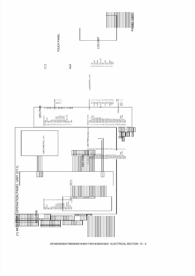
8/9/2019 AR-M318 SM
http://slidepdf.com/reader/full/ar-m318-sm 147/159
AR-M256/M257/M258/M316/M317/M318/5625/5631 ELECTRICAL SECTION 12 - 3
( 1 ) M C U P W B -
O P E R A T I O N P
A N E L U N I T ( 2 / 1 1 )
C N 1 ( 5 2 6 1 0 - 1 8 7 1 )
L C D U N I T
( F F C )
< O P U P W B F F C >
( F F C )
< K E
Y P W B h a r n e s s >
C N 9 ( 5 2 2 0 7 - 1 8 1 9 )
1 2 3 4 5 6 7 8 9 1 0 1 1 1 2 1 3 1 4 1 5 1 6 1 7 1 8
M C U P W B
G N D
+ 5 V s u b
/ W a k e U p_
K e y
S t a n d b y_ L E D
G N D
/ R X D
_ O P U
/ T X D
_ O P U
S R D Y
_ O P U
/ C L K
_ O P U
C R D Y
_ O P U
R E S
_ O P U
+ 3 . 3 V
+ 3 . 3 V
G N D
+ 5 V G N D
+ 2 4 V_ O
P
G N D
1 2 3 4 5 6 7 8 9 1 0 1 1 1 2 1 3 1 4 1 5 1 6 1 7 1 8
D I S P
D - G
N D D
3 D 2
D - G
N D D
1 D 0
3 . 3 V
_ E X T
D - G
N D M C
P
D - G
N D L P V
0
1 2 3 4 5 6 7 8 9 1 0 1 1 1 2 1 3
V E E
1 4 1 5
C N 5 ( 5 2 7 4 6 - 1 5 7 1 )
C O M 2
C O M 0
/ S E G 3
/ S E G 2
/ S E G 1
/ S E G 0
S C A N 4
S C A N 2
S C A N 3
S C A N 1
S C A N 0
S E N S E 4
S E N S E 3
S E N S E 2
S E N S E 1
S E N S E 0
I N F O
_ L E D
2 3 4 5 6 7 8 9 1 0 1 1 1 2 1 3 1 4 1 5 1 6 1 7 1 8 1 9 G N D
5 V s u b
S T A R T_ L E D
/ B Z R
_ P W M
/ S T A R T_ K E Y
2 0 2 1 2 2 2 3 2 4 C N 2 ( 5 2 2 7 1 - 2 4 7 9 )
C O M 2
C O M 1
C O M 0
/ S E G 3
/ S E G 2
/ S E G 1
/ S E G 0
S C A N 4
S C A N 2
S C A N 3
S C A N 1
S C A N 0
S E N S E 4
S E N S E 3
S E N S E 2
S E N S E 1
S E N S E 0
I N F O
_ L E D
G N D
5 V s u b
S T A R T
_ L E D
/ B Z R
_ P W M
/ S T A R T_ K E Y
1 2 3 4 5 6 7 8 9 1 0 1 1 1 2 1 3 1 4 1 5 1 6 1 7 1 8 1 9 2 0 2 1 2 2 2 3
C N 1 ( I M S A - 9 6 1 9 S - 2 4 C - T
B )
/ C C F T
1 2
C C F T +
C N 6
( S M 0 2 ( 8 . 0 ) B - B
H S - 1 - T
B )
D I S P
D - G
N D
D 3
D 2
D - G
N D
D 1
D 0
3 . 3 V
_ E X T
D - G
N D
M C P
D - G
N D
L P V 0
V E E
1 2 3 4 5 6 7 8 9 1 0 1 1 1 2 1 3 1 4 1 5
( F F C )
< L C D M F F C >
T O U
C H P A N E L
X 2 / Y 2 /
Y 1
1 2 3 4
X 1
C N 4 ( 5 2 2 7 1 - 0 4 6 9 )
P A N E L U N I T
G N D
2 4
G N D
1
K E Y P W B
O P U P W B
G N D
+ 5 V s u b
/ W a k e U p_
K e y
S t a n d b y_ L E D
G N D
/ R X D_ O P U
/ T X D_ O P U
S R D Y_ O P U
/ C L K
_ O P U
C R D Y_ O P U
R E S_ O P U
+ 3 . 3 V
+ 3 . 3 V
G N D
+ 5 V G N D
+ 2 4 V_ O
P
G N D
C O M 1
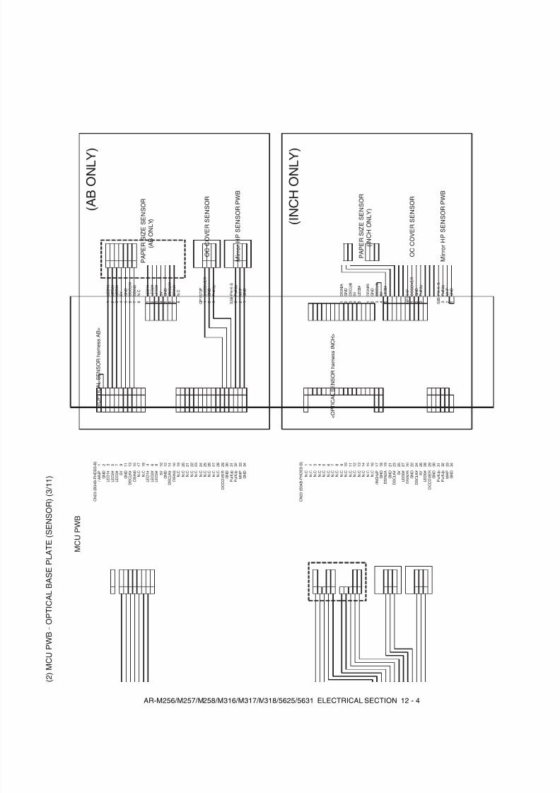
8/9/2019 AR-M318 SM
http://slidepdf.com/reader/full/ar-m318-sm 148/159
AR-M256/M257/M258/M316/M317/M318/5625/5631 ELECTRICAL SECTION 12 - 4
( 2 ) M C U P W B -
O P T I C A L B A S E P L A T E ( S E N S O R ) ( 3 / 1 1 )
C N 2 3 ( B 3 4 B - P
H D S S - B
)
( A B O N L Y )
P A P E R S I Z E S E N S O R
( A B O N L Y )
< O P T I C A L S E N S O R h a r n e s s A B >
O C C O V E R S E N S O R
M i r r o r H P S E N S O R P W B
D S I N 0
D S C L K #
G N D 5 V
L E D 3 #
L E D 2 #
L E D 1 #
G N D
/ A B J P
1 2 3 5 7 9 1 1 1 3 1 5 1 7 1 8 1 9 2 0 2 1 2 2 2 3 2 4
G N D
M H P
P u l l U p
P u l l U p
G N D
O C C O V E R
2 5 2 6 2 7 2 8 2 9 3 0 3 1 3 2 3 3
G N D
/ I N C H J P
N . C
1 2 3 4 5 6 7 8 9 1 0 1 1 1 2 1 3 1 4 1 5 1 6 1 7 1 8
G N D
M H P
P u l l U p
P u l l U p
G N D
O C C O V E R
2 9 3 0 3 1 3 2 3 3
D S I N 0
D S C L K #
G N D
5 V L E D 3 #
L E D 2 #
L E D 1 #
1 2 3 4 5 6 7
G N D
M H P
P u l l U p
P u l l U p
G N D
O C C O V E R
1 2 3 3 2 1 S 3 B - P
H - K - S
G P 1 S 7 3 P
N . C
N . C
N . C
N . C
N . C
N . C
N . C
N . C
N . C
N . C
N . C
N . C
3 4
( I N C H O N L Y )
D S C L K #
D S C L K #
G N D
G N D
D S I N 2 B
D S I N 2 A
1 1 2 2 3 3
L E D 0 #
L E D 0 #
5 V 5 V
4 4 5 5
D S I N 3
D S C L K #
G N D 5 V
L E D 3 #
L E D 2 #
L E D 1 #
4 6 8 1 0 1 2 1 4 1 6
D S I N 3
D S C L K #
G N D
5 V L E D 3 #
L E D 2 #
L E D 1 #
N . C
8
N . C
8 1 2 3 4 5 6 7
D S C L K #
D S C L K #
G N D
G N D
D S I N 2 B
D S I N 2 A
1 9 2 0 2 1 2 2 2 3 2 4
L E D 0 #
L E D 0 #
5 V 5 V
2 5 2 6 2 7 2 8
G N D
M H P
P u l l U p
P u l l U p
G N D
O C C O V E R
1 2 3 3 2 1 S 3 B - P
H - K - S
G P 1 S 7 3 P
3 4
N . C
N . C
N . C
N . C
N . C
N . C
N . C
N . C
N . C
N . C
N . C
N . C
N . C
N . C
N . C
M C U P W B
P A P E R S I Z E S E N S O R
( I N C H O N L Y )
< O P T I C A L S E N S O R h a r n e s s I N C H >
O C C O V E R S E N S O R
M i r r o r H P S E N S O R P W B
C N 2 3 ( B 3 4 B - P
H D S S - B
)
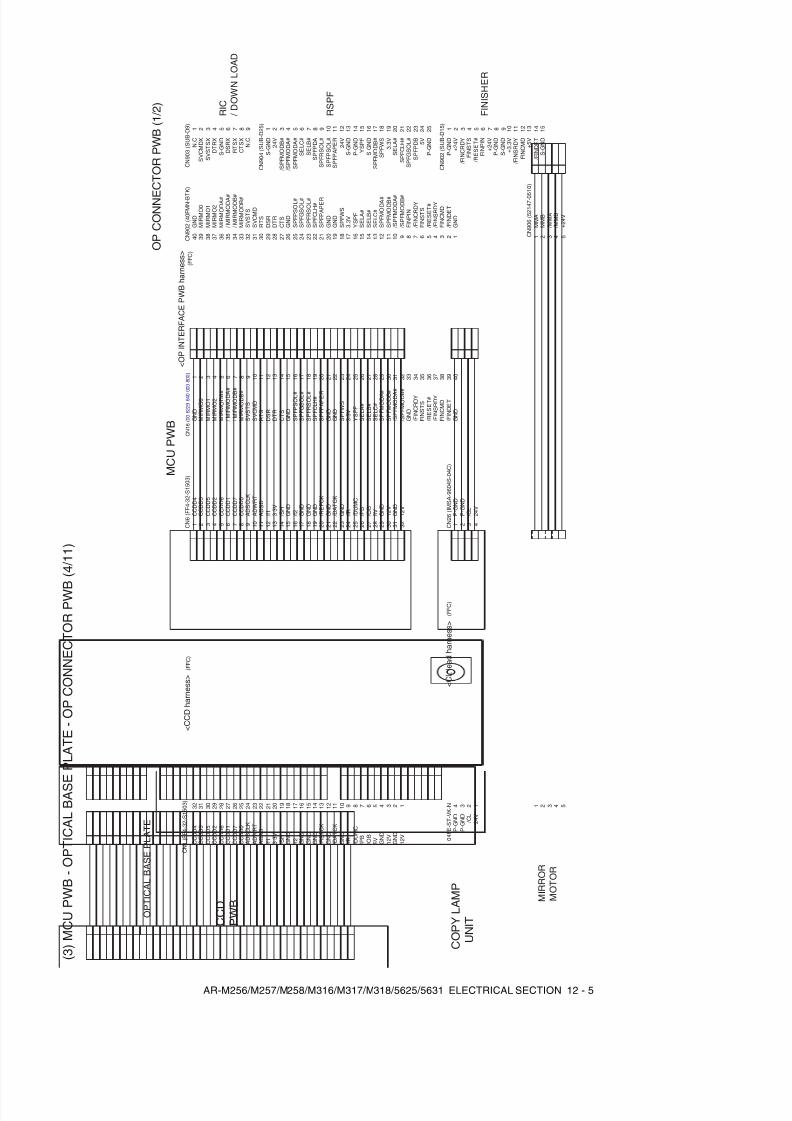
8/9/2019 AR-M318 SM
http://slidepdf.com/reader/full/ar-m318-sm 149/159
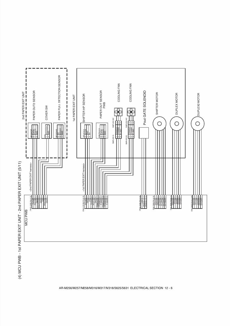
8/9/2019 AR-M318 SM
http://slidepdf.com/reader/full/ar-m318-sm 150/159
AR-M256/M257/M258/M316/M317/M318/5625/5631 ELECTRICAL SECTION 12 - 6
( 4 ) M C U P W B -
1 s t P A P E R E X I T U N I T -
2 n d P A P E R E X I T U N I T ( 5 / 1 1 )
C N 4 ( B 5 B - P
H - K z z z R
)
S W 2 4 V
D P X 2 A
D P X 2 B
/ D P X 2 A
/ D P X 2 B
1 2 3 4 5
D U P L E X 2 M O T O R
P A P E R O U T 2 S E N S O R
C N 2 0 ( S 8 B - P
H - K - S
)
D 2 X
G P 1 S Q 4 4 S
C O V E
R S W
P A P E R F U L L D E T E C T I O N S E N S O R
2 n d P
A P E R E X I T U N I T
< 2 n d P A P E R E X I T h a r n e s s >
P u l l U p
P O U T 2
G N D
P O U T C O V
G N D 5 V
P F U L L 2
G N D
P O U T C O V
1
G N D
5 V
2 2
P F U L L 2
3
G N D
1 G P 1 S Q 7 3 P
3
P O U T 2
G N D
1 2
P u l l U p
1 s t P A P E R E X I T U N I T
P o u t G A
T E S O L E N O I D
C N 2 2 ( S 3 B - P
H - K - M
)
+ 2 4 V
1
/ P G S O L 1
/ P G S O L 2
2 3
C N 1 ( B 5 B - P
A S K - 1 )
D U P L E X M O T O R
S W 2 4 V
1
D P X A
D P X B
2 3
/ D P X A
/ D P X B
4 5
S H I F T E R M O T O R
C N 2 ( S 6 B - P
H - K - S
)
S W 2 4 V
S W 2 4 V
1 2
S F T D A #
S F T D B #
3 4
/ S F T D A #
/ S F T D B #
5 6
S H I F T E
R H P S E N S O R
C N 2 4 ( S 1 2 B - P
H - K - S
)
S 3 B - P
H - K - S
C O O L I N G F A N
C O O L I N G F A N
G P 1 A 7 1 L 3
P A P E R O U T S E N S O R
P W B
< 1 s t P A P E R E X I T h e r n e s s >
S F T H P
1
G N D 5 V
2 3
P u l l U p
4
P O U T 1
G N D
5 6
T F A N O U T
7
/ T F A N M D
P - G
N D
8 9 1 0
/ T F A N M D
P - G
N D
1 1 1 2
S F T H P
2
G N D
1 3 3
G N D
2 1
S M P - 0 3 V - N
C
S M R - 0 3 V - N
1 2 3
1 2 3
S M P - 0 3 V - N
C
S M R - 0 3 V - N 1 2 3
1 2 3
5 V P u l l U p
P O U T 1
T F A N O U T
/ T F A N M D
P - G
N D
/ T F A N M D
P - G
N D
T F A N O U T
T F A N O U T
1 2 3 4 5 6 7 8
M C U P W B

8/9/2019 AR-M318 SM
http://slidepdf.com/reader/full/ar-m318-sm 151/159
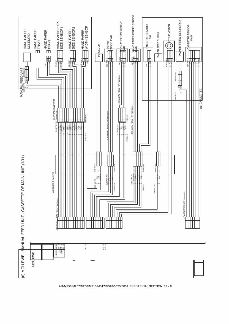
8/9/2019 AR-M318 SM
http://slidepdf.com/reader/full/ar-m318-sm 152/159
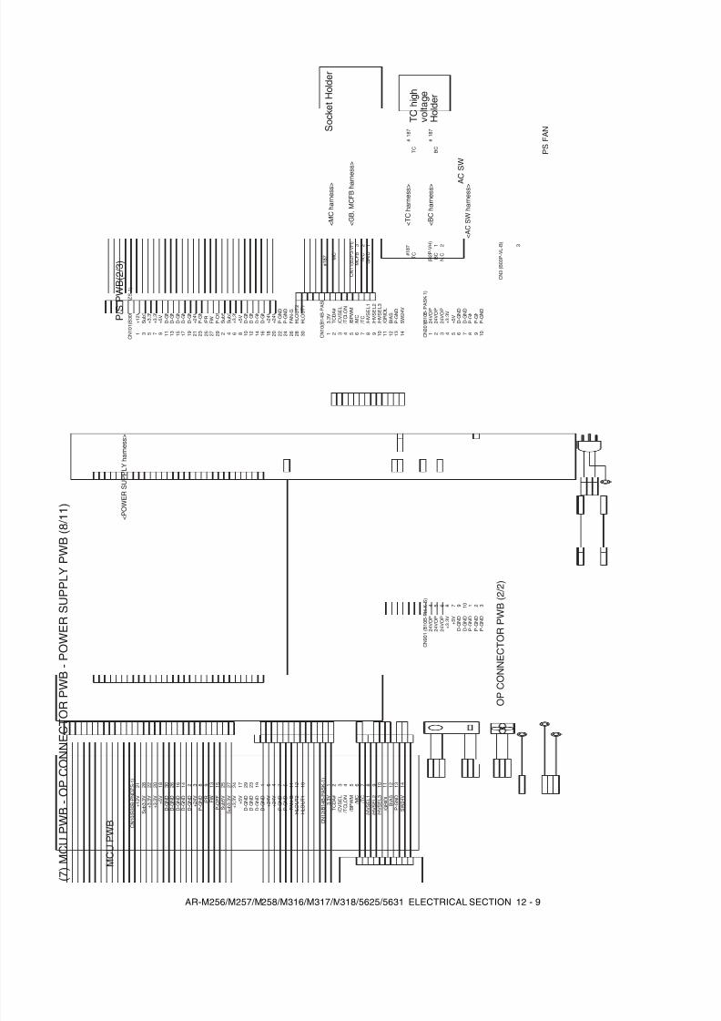
8/9/2019 AR-M318 SM
http://slidepdf.com/reader/full/ar-m318-sm 153/159
AR-M256/M257/M258/M316/M317/M318/5625/5631 ELECTRICAL SECTION 12 - 9
( 7 ) M C U P W B -
O P C O N N E C T O R P W B -
P O W E R S U P P L Y P W B ( 8 / 1 1 )
M C U P W B
A C
S W
F - G
N D
C N 1 0 2 ( B 3 B - P
H - K - S
)
C N 1 ( B 0 3 P - V
L )
C N 2 ( B 0 3 P - V
L - R )
C N 1 1 ( B 2 P 3 - V H )
# 1 8 7
# 1 8 7
S o c k e t H o l d e r
T C h i g h
v o l t a g e
H o l d e r
C N 1 0 ( B 1 4 B - P
A S K - 1 )
< M C h a r n e s s >
< G B
, M C F B h a r n e s s >
< T C h a r n e s s >
< B C h a r n e s s >
< A C S W
h a r n e s s >
C N 1 0 1 ( B 3 0 B - P
N D Z S - 1 )
C N 1 2 ( B 1 4 B - P
A S K - 1 )
C N 1 0 ( B 3 0 B - P
N D Z S - 1 )
S W 2 4 V
P - G
N D
B I A S
/ G R I D L
/ H V S E L 3
/ H V S E L 2
/ H V S E L 1
/ T C
/ M C
/ B P W M
/ T C L O N
/ C V S E L
T C D A #
3 . 3 V
1
P - G
N D
P - G
N D
P - G
N D
+ 2 4 V + 5 V
+ 1 2 V
+ 3 . 3 V
+ 3 . 3 V
P - O
F F
H L O U T 2
H L O U T 1
/ P R
F W
S u b 5 V
F A N - G
D - G
N D
S u b 3 .
3 V
< P O W E R S U P P L Y h a r n e s s >
G N D
N . C
/ P S F A N
3 2 1
N E U T R A L
N . C
L I V E
3 2 1
P S F A N
A C - N
I N N
. C
A C - L
I N
2 1
A C - N
O U T
N . C
A C - L
O U T
3 2 1
B C
1
# 1 8 7
B C
# 1 8 7
T C
T C
G R I D
N . C
M C F B
3 2 1
M C
1 2 3 4 5 6 7 8 9 1 0 1 1 1 2 1 3
2 3 4 5 6 7 8 9 1 0 1 2 1 3 1 4 1 1
C N 9 0 1 ( B 1 0 B - P
H - K - S
) 4
C N 2 0 1 ( B 1 0 B - P
A S K - 1 )
1
D - G
N D
+ 3 . 3 V
+ 5 V 2 4 V O P
P - G
N D
P - G
N D
1 4
6 5 8 7 9 1 1 0 2 3
2 3 4 5 6 7 8 9 1 0
O P C O N N E C T O R P W B ( 2 / 2 )
D - G
N D
D - G
N D
D - G
N D
D - G
N D
S u b 3 .
3 V
+ 3 . 3 V
+ 5 V
D - G
N D
D - G
N D
D - G
N D
D - G
N D
+ 2 4 V
+ 2 4 V
P - G
N D
P - G
N D
P - G
N D
+ 2 4 V
+ 5 V + 1 2 V
+ 3 . 3 V
+ 3 . 3 V
P - O
F F
H L O U T 2
H L O U T 1
/ P R
F W S u b 5 V
F A N - G
D - G
N D
S u b 3 .
3 V
D - G
N D
D - G
N D
D - G
N D
D - G
N D
S u b 3 .
3 V
+ 3 . 3 V
+ 5 V D - G
N D
D - G
N D
D - G
N D
D - G
N D
+ 2 4 V I N T
+ 2 4 V I N T
S W 2 4 V
P - G
N D
B I A S
/ G R I D L
/ H V S E L 3
/ H V S E L 2
/ H V S E L 1
/ T C
/ M C
/ B P W M
/ T C L O N
/ C V S E L
T C D A #
3 . 3 V
D - G
N D
P - G
N D
2 4 V O P
2 4 V O P
D - G
N D
+ 3 . 3 V
+ 5 V
2 4 V O P
P - G
N D
P - G
N D
D - G
N D
P - G
N D
2 4 V O P
2 4 V O P
3
C N 3 ( B 0 3 P - V
L - B )
( B 2 P - V
H )
N . C
2
1 3 5 7 9 1 1 1 3 1 5 1 7 1 9 2 1 2 3 2 5 2 7 2 9 2 4 6 8 1 0 1 2 1 4 1 6 1 8 2 0 2 2 2 4 2 6 2 8 3 0
2 1 2 8 2 2 2 0 1 8 3 0 2 6 1 6 1 4 2 3 8 9 1 3 1 5 2 5 2 7 2 4 1 7 2 9 2 3 1 9 1 6 4 7 5 1 1 1 2 1 0
P / S P W B ( 2 / 3 )
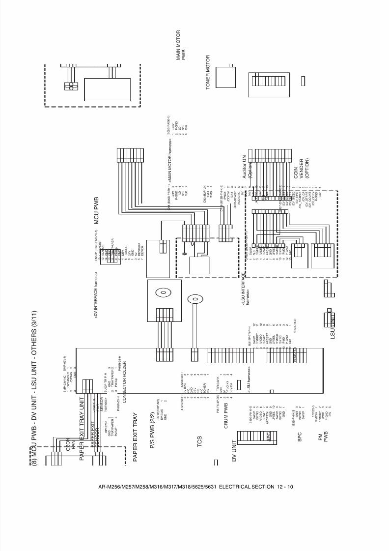
8/9/2019 AR-M318 SM
http://slidepdf.com/reader/full/ar-m318-sm 154/159
AR-M256/M257/M258/M316/M317/M318/5625/5631 ELECTRICAL SECTION 12 - 10
( 8 ) M C U P W B -
D V U N I T - L
S U U N I T -
O T H E R S ( 9 / 1 1 )
L S U U N I T
B U 0 3 P - T
R - P - H
P M
P W B
1 7 7 6 2 2 - 5
A P C
B 1 0 B - P
H - K - S
B P C
B 3 B - P
H - K - S
< L S U h a r n e s s >
< D V I N T E R F A C E
h a r n e s s >
S W 5 V
/ S Y N C
/ V I D E O
/ S A M P
A P C S T T
G N D
L P S E L
/ P M C L K
/ P M R D Y
/ P M D
P - G
N D
2 4 V
2 3 1 1 5 4 6 7 8 9 1 0 1 1 2
1 3 4 5 6 7 9 8 2 1 0 1 1
/ P M D
P - G
N D
2 4 V
5 4 3 2 1
G N D
/ S Y N C
/ P M C L K
/ P M R D Y
3 2 1 1 2 3 1 0 9 8 7 6 4
1 2 1 3 4 5 6 7 8 1 0 9 3 1 1
D V U N I T
5 2 0 2 5 - 0 8 1 1
5 1 0 1 0 - 0 8 1 1
T S R - 0 4 V - K
P I 8 - F X - 4 P - D
S
C N 5 0 2 ( B 1 4 B - P
N D Z S - 1 )
G N D
1 D E V C L K #
5 D E V I D #
7 5 V
3
G N D
1
D E V C L K #
3 4
5 V
2
1 3 4 2
T C S
G N D
4
D E V
3
T O N E R
2
2 4 V
1
D V B I A S
8
N . C
7
N . C
6
N . C
5
4 3 2 1 8 7 6 5
G N D
2 D E V
4 T O N E R
6 2 4 V
8
C N 1 2 ( B 0 2 P - N
V )
D V B I A S
G N D
1 2
P / S P W B ( 2 / 2 )
P A P E R E X I T
S E N S O R
G P 1 S 7 3 P
G N D
T R A Y P A P E R
P u l l U
P
3 2 1
G N D
1 3 T R A Y P A P E R
P u l l U p
1 1 9
3 T R A Y P A P E R
1 G N D
2
3 2 1
P A P E R E X I T T R A Y U N I T
< P A P E R
E X I T
S E N S O R
h a r n e s s >
P H N R - 0 3 - H
P H N R - 0 3 - H
P A P E R E X I T T R A Y
C O N N E C T O R H O L D E R
C N 3 ( B 2 P - V
H )
T O N E R M O T O R
T M D / T M D
1 2
A u d i t o r
U N
( O p t i o n )
2 4 V
P - G
N D
/ C V
_ C O P Y
/ C V
_ C O U N T
/ C V
_ S T A R T
/ C V
_ C A
/ C V
_ S T A P L E
/ C V
_ D P X
/ C V
_ S I Z E 0
/ C V
_ S I Z E 1
/ C V
_ S I Z E 2
/ C V
_ S I Z E 3
1 2 3 4 5 6 7 8 9 1 0 1 1 1 2
C N 2 7 ( B 1 2 B - X A
S K - 1 )
C O I N
V E N D E R
( O P T I O N )
P - G
N D
/ P N C - a 2 4 V
/ A U D - T C N . C 2 4 V G N D 5 V
/ A U D - D
T C
/ A U D - R
E A D Y
/ C O P Y #
/ P N C #
/ C A #
1 2 3 4 5 6 7 8 9 1 0 1 1 1 2 1 3
C N 2 8 ( B 1 3 B - P H
- K - S
)
M A I N M O T O R
P W B
< M A I N M O T O R h a r n e s s >
+ 2 4 V
P - G
N D
L D S / S
C L K
+ 2 4 V
P - G N
D L D S / S C L
K
O Z O N
F A N
G N D
/ O Z F A N
O Z F A N O U T
1 4 1 2 1 0
G N D
/ O Z F A N
O Z F A N O U T
3 2 1
3 2 1
S M P - 0 3 V - N
C
S M R - 0 3 V - N
N . C
1 2
S W 5 V
/ S Y N C
/ V I D E O
/ S A M P
A P C S T T
G N D
L P S E L
/ P M C L K
/ P M R D Y
/ P M D
P - G
N D
2 4 V
C N 5 0 1 ( B 1 3 B - P
A S K - 1 )
C R U M P W B
< L S U I N T E R F A C E
h a r n e s s >
P u l l U p
1 2
S W 5 V
/ V I D E O
/ S A M P
A P C S T T #
G N D
L P S E L
5
/ S Y N C
G N D
/ S Y N C
S W 5 V
S W 5 V
P H N R - 1 2 - H
P H N R - 1 2 - H
B U 1 2 P - T
R - P - H
C N 8 ( B 0 5 B - P A
S K - 1 )
( B 0 5 B - P
A S K - 1 )
D E V I D #
5 4 3 2 1
1 2 3 4 5
M C U P W B
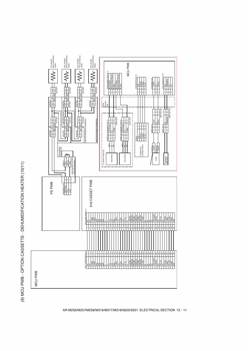
8/9/2019 AR-M318 SM
http://slidepdf.com/reader/full/ar-m318-sm 155/159
AR-M256/M257/M258/M316/M317/M318/5625/5631 ELECTRICAL SECTION 12 - 11
( 9 ) M C U P W B -
O P T I O N C A S S E T T E -
D E H U M I D I F I C A T I O N H E A T E R ( 1 0 / 1 1 )
X L P - 0 2 V
X L P - 0 2 V
D H - L
D H - L
N E U T R A L
N E U T R A L
X L R - 0 2 V
X L R - 0 2 V
C N 4 ( B 2 P 3 - V H )
1 7 2 0 7 4 - 1
X L P - 0 2 V
X L P - 0 2 V
N E U T R A L
D H - L
D H - L
D H - L
( N . C
)
1 7 2 0 7 4 - 7
N E U T R A L
N E U T R A L
L I V E
L I V E
X L R - 0 2 V
X L R - 0 2 V
< D E H U M I D I F I C A T I O N
H E A T E R S W
A N 2 >
X L P - 0 2 V
X L P - 0 2 V
D H - L
D H - L
N E U T R A L
N E U T R A L
X L R - 0 2 V
X L R - 0 2 V
C N 1 7 ( B 4 0 B - P
N D Z S - 1 )
C N 9 ( B 4 0 B - P
N D K S - 1 )
2 4 V
2 4 V
2 4 V
2 4 V
X L P - 0 2 V
P - G
N D
P - G
N D
D H - L
P - G
N D
P - G
N D
N E U T R A L
G N D
G N D
< H E A T E R B R A N C H H A R N E S S >
< H E A T E R B R A N C H H A R N E S S >
< H E A T E R B R A N C H H A R N E S S >
X L R - 0 2 V
G N D
G N D
G N D
G N D
G N D
G N D
3 1 s h e e t m o d e l o n l y
I L S W
h a r n e s s
A N 2
5 V
5 V
5 V
5 V
P H N R - 0 3 - H + B
U 0 3 P - T R -
P - H
C N 5 0 4 ( B 0 6 B - C
Z H K - B - 1 )
3 . 3 V
3 . 3 V
R E D
P O U T F A N #
P O U T F A N #
3 . 3 V
3 . 3 V
Y L
N . C
/ P O U T F A N C T R L ( N
. C )
G N D
G N D
B K
P - G
N D
P - G
N D
L U M 2 #
L U M 2 #
0 3 C K - 6 H - P
P O U T F A N #
Y 1 A
Y 1 A
/ P O U T F A N C T R L ( N
. C )
P C S 2 #
P C S 2 #
P H N R - 0 3 - H + B
U 0 3 P - T R -
P - H
P - G
N D
Y 1 B
Y 1 B
R E D
P O U T F A N #
P C L 2 #
P C L 2 #
Y L
N . C
Y 2
Y 2
B K
P - G
N D
L U M 1 B #
L U M 1 B #
0 3 C K - 6 H - P
C S S E L A #
C S S E L A #
T R C L B #
T R C L B #
C S S E L C #
C S S E L C #
Z H R - 4
C N 5 0 3 ( P A P - 0 4 V - S
)
P C S 1 B #
P C S 1 B #
5 V N
5 V N
C S S E L B #
C S S E L B #
H U D - M
H U D - M
P C L 1 B #
P C L 1 B #
D - G
N D
D - G
N D
B l #
B l #
T H
_ M
T H_ M
A l #
A l #
/ B l #
/ B l #
/ A l #
/ A l #
S o l d e r i n g
S o l d e r i n g
S M R - 0 3 V - N
C N 1 8 ( B 3 P - V
H )
/ O P C A S S E L
/ O P C A S S E L
2 4 V I N T
2 4 V I N T
2 4 V I N T
L U M 1 A #
L U M 1 A #
N . C
N . C
2 4 V
2 4 V
S W 2 4 V
S W 2 4 V
S W 2 4 V
T R C L A #
T R C L A #
S M P - 0 3 V - N
C
2 4 V
2 4 V
S M R - 0 2 V - N
C N 1 1 ( B 0 4 B - P
H - K - R
)
P C S 1 A #
P C S 1 A #
2 4 V
2 4 V
P - G
N D
P - G
N D
/ P R E M S O L
/ P R E M S O L
P C L 1 A #
P C L 1 A #
S M P - 0 2 V - N
C
N . C
P - G
N D
P - G
N D
N . C
G N D
G N D
2 3 4
A - 2
A - 1
B - 2
1 5 6
B - 2
A - 2
A - 1
A - 2
A - 1
B - 1
7
C - 2
C - 1
3 9 2 2
8 9 1 0 1 1 1 2 1 3
2 3 2 4
A - 1
1 4 1 5 1 6 1 7 1 8 1 9
A - 2
A - 1
A - 2
A - 1
A - 2
A - 1
A - 2
C - 2
C - 1
B - 1 B - 2
B - 1
3 2 1
A - 2
A - 1
C - 2
C - 1
4 0 1 2 3 4 5 1 4 1 5 1 6 1 7
2 0 2 1 2 2 2 3 2 4 2 5 2 6 2 7 2 8 2 9 3 0 3 2 3 3 3 4 3 1 3 5 3 6 3 7 3 8 3 9 4 0
6 7 8 9 1 0 1 1 1 2 1 3 1 8 1 9 2 0 2 1 2 5 2 6 2 7 2 8 3 5 2 9 3 0 3 1 3 2 3 6 3 7 3 8 3 3 3 4
1 2 3 4
6
1 2 3
3 2 1
5 4
3
1
1 2
1
3
2
2
3 2 1 1 4 3 2 1 3 4
1
3
2 3
1 2
1
3
1 2
2
2
M C U P W B
1 s t c a s s e t t e
D e h u m i d
i f i c a t i o n
h e a t e r
2 n d c a s s e t t e
D e h u m i d
i f i c a t i o n
h e a t e r
3 r d c a s s e
t t e
D e h u m i d
i f i c a t i o n
h e a t e r
4 t h c a s s e
t t e
D e h u m i d
i f i c a t i o n
h e a t e r
D E H U M I D I F I -
C A T I O N S W
P S P W B
2 n d C A S S E T P W
B
P O U T F A N
P O U T F A N
M C U P W B
T e m p e r a t u r e
h u m i d i t y s e n s o r
I L S W
S e p a r a t i o n
p a w l S O L
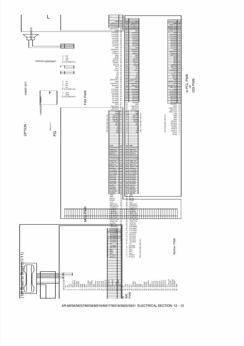
8/9/2019 AR-M318 SM
http://slidepdf.com/reader/full/ar-m318-sm 156/159
AR-M256/M257/M258/M316/M317/M318/5625/5631 ELECTRICAL SECTION 12 - 12
( 1 0 ) B o a d
t o B o a d
( 1 1 / 1 1 )
G N D 9 G N D 1 0
5 V s u b 1
3 . 3 V s u b 2 3
3 . 3 V s u b 4 / R E S E T / P W O F F
5 6
/ P R L I N E 7 / H S Y N C 8
1 9 2 0
G N D 1 1
P S S T S
/ P C L P A G E 1 2 1 3
P C L C M D 1 4 / P C L C R D Y
G N D 1 5 1 6 1 7 1 8
/ P C L A C K 0 P 2 9 G N D 3 0
2 1 2 2 2 3 2 4
G N D / P C L P R D
2 5 2 6
/ P C L A C K 1 P 2 7 G N D 2 8
G N D 3 9 G N D 4 0
5 V s u b 3 1
/ P R I N T W U
3 2 3 3 3 4
3 . 3 V s u b 3 . 3 V
3 5 3 6
/ S C L I N E 3 7 / R E A D Y 3 8
4 9 5 0
G N D 4 1 G N D / P C L D E T
4 2 4 3
P C L S T S 4 4 / P C L S R D Y
G N D 4 5 4 6 4 7 4 8
5 9 6 0
5 1 5 2 5 3 5 4
G N D / P C L R E Q 1 P
5 5 5 6
/ P C L C S 1 P 5 7 5 8
G D A T A 4 G D A T A 2
G D A T A 8 G D A T A 6
G D A T A 0
G D A T A 1 2 G D A T A 1 0
G D A T A 1 4
G D A T A 7 G D A T A 5
G D A T A 1 1 G D A T A 9
G D A T A 3 G D A T A 1
G D A T A 1 3 G D A T A 1 5
/ P C L R E Q 0 P / P C L C S 0 P
G N D
5 V s u b
G N D
5 V s u b
9 1 0
1 2 3 4 5 6 7 8
1 9 2 0
1 1 1 2 1 3 1 4 1 5 1 6 1 7 1 8
2 9 3 0
2 1 2 2 2 3 2 4 2 5 2 6 2 7 2 8
3 9 4 0
3 1 3 2 3 3 3 4 3 5 3 6 3 7 3 8
4 9 5 0
4 1
4 2 4 3 4 4 4 5 4 6 4 7 4 8
5 9 6 0
5 1 5 2 5 3 5 4 5 5 5 6 5 7 5 8
/ P C L P R D
/ P C L P A G E
G N D / F A X A C K 0 P
/ F A X P R D / F A X C R D Y
F A X C M D / F A X P A G E
/ P C L A C K 0 P / P C L A C K 1 P
G D A T A 4
G D A T A 2
P C L C M D
/ F W U A X G D A T A 1 4 G D A T A 1 2 G D A T A 1 0
G D A T A 8 G D A T A 6
E X T R S 5 V s u b
G D A T A 0 / P S S T S / H S Y N C / P R L I N E
/ P W O F F #
G N D / R E S E T
G N D
/ P C L C S 1 P / P C L R E Q 1 P
3 . 3 V / F A X C S 0 P
/ F A X R E Q 0 P / F A X S R D Y
F A X S T S / F A X D E T
/ P C L C S 0 P / P C L R E Q 0 P
G D A T A 7 G D A T A 5
/ P C L S R D Y P C L S T S
/ P C L D E T / P R I N T W U
G D A T A 1 5 G D A T A 1 3 G D A T A 1 1
G D A T A 9
3 . 3 V s u b 3 . 3 V s u b
G D A T A 3 G D A T A 1
5 V / R E A D Y / S C L I N E
G N D G N D 2 4 V
/ P C L C R D Y
M C U P W B
M o t h e r - P W
B
t o I M C
P W B
C N 7 ( T X 2 5 - 6 0 P - 6 S
T - H
1 )
t o P C L P W B
o r
G D I P W B
C N 5 ( T X 2 5 - 6 0 P - 1 2 S T - H
1 )
C N ( T X 2 5 - 6 0 P - 1 2 S T - H
1 )
C N 3 ( T X 2 4 - 6 0 R - 1 2 S T - H
1 )
G N D
9
G N D
1 0 5 V
1
5 V 3 . 3 V
2 3
3 . 3 V
4
/ R E S E T #
/ P W O F F #
5 6
/ P R L I N E
7
/ H S Y N C
8 1 9 2 0 G N D
1 1 N
. C / E S P A G E
1 2 1 3 E S C M D
1 4 / E S C R D Y
G N D
1 5 1 6 1 7 1 8 / E S A C K 0 P
2 9 G N D
3 0 2 1 2 2 2 3 2 4 N
. C / E S A C K 1 P
2 5 2 6 N
. C
2 7 / E S P R D
2 8 G N D
3 9 G N D
4 0 5 V
3 1 5 V 3 .
3 V
3 2 3 3 3 . 3 V
3 4 N
. C N
. C
3 5 3 6 / S C L I N E
3 7 / R E A D Y
3 8 4 9 5 0 G N D
4 1 N
. C / E S D E T
4 2 4 3 E S S T S
4 4 / E S S R D Y
G N D
4 5 4 6 4 7 4 8 5 9 6 0 5 1 5 2 5 3 5 4 N
. C / E S R E Q 1 P
5 5 5 6 / E S C S 1 P
5 7 5 8 G D A T A 4
G D A T A 2
G D A T A 8
G D A T A 6
G D A T A 0
G D A T A 1 2
G D A T A 1 0
G D A T A 1 4
G D A T A 7
G D A T A 5
G D A T A 1 1
G D A T A 9
G D A T A 3
G D A T A 1
G D A T A 1 3
G D A T A 1 5
/ E S R E Q 0 P
/ E S C S 0 P
G N D
9 1 0
1 2 3 4 5 6 7 8
1 9 2 0
1 1 1 2 1 3 1 4 1 5 1 6 1 7 1 8
2 9 3 0
2 1 2 2 2 3 2 4 2 5 2 6 2 7 2 8
3 9 4 0
3 1 3 2 3 3 3 4 3 5 3 6 3 7 3 8
4 9 5 0
4 1
4 2 4 3 4 4 4 5 4 6 4 7 4 8
5 9 6 0
5 1 5 2 5 3 5 4 5 5 5 6 5 7 5 8
/ P C L P R D
/ P C L P A G E
G N D / F A X A C K 0 P
/ F A X P R D / F A X C R D Y
F A X C M D / F A X P A G E
/ P C L A C K 0 P / P C L A C K 1 P
G D A T A 4
G D A T A 2
P C L C M D
/ F W U A X G D A T A 1 4 G D A T A 1 2 G D A T A 1 0
G D A T A 8 G D A T A 6
E X T R S 5 V s u b
G D A T A 0 / P S S T S / H S Y N C / P R L I N E / P W O F F #
G N D / R E S E T
G N D
/ P C L C S 1 P / P C L R E Q 1 P
3 . 3 V / F A X C S 0 P
/ F A X R E Q 0 P / F A X S R D Y
F A X S T S / F A X D E T
/ P C L C S 0 P / P C L R E Q 0 P
G D A T A 7 G D A T A 5
/ P C L S R D Y P C L S T S
/ P C L D E T / P R I N T W U
G D A T A 1 5 G D A T A 1 3 G D A T A 1 1
G D A T A 9
3 . 3 V s u b 3 . 3 V s u b
G D A T A 3 G D A T A 1
5 V / R E A D Y / S C L I N E
G N D G N D 2 4 V
/ P C L C R D Y
C N 1 ( T X 2 5 - 6 0 P
- 1 2 S T - H
1 )
/ P R L I N E 9 / H S Y N C 1 0
2 4 V 1 2 4 V 5 V
2 3
F A X W U
4 3 . 3 V 3 . 3 V
5 6
/ R E S E T 7
/ P W O F F 8
1 9 2 0
G N D 1 1
5 V s u b
/ F A X P A G E 1 2 1 3
F A X C M D 1 4 / F A X C R D Y
G N D 1 5 1 6 1 7 1 8
/ F A X A C K 0 P 2 9 G N D 3 0
2 1 2 2 2 3 2 4
G N D / F A X P R D
2 5 2 6
/ F A X A C K 1 P 2 7 G N D 2 8
/ S C L I N E 3 9
/ R E A D Y 4 0
2 4 V 3 1 2 4 V 5 V
3 2 3 3 3 4
3 . 3 V 3 . 3 V
3 5 3 6
E X T R S 3 7 3 8
4 9 5 0
G N D 4 1 G N D / F A X D E T
4 2 4 3
F A X S T S 4 4 / F A X S R D Y
G N D 4 5 4 6 4 7 4 8
5 9 6 0
5 1 5 2 5 3 5 4
G N D / F A X R E Q 1 P
5 5 5 6
/ F A X C S 1 P 5 7 5 8
G D A T A 4 G D A T A 2
G D A T A 8 G D A T A 6
G D A T A 0
G D A T A 1 2 G D A T A 1 0
G D A T A 1 4
G D A T A 7 G D A T A 5
G D A T A 1 1 G D A T A 9
G D A T A 3 G D A T A 1
G D A T A 1 3 G D A T A 1 5
/ F A X R E Q 0 P / F A X C S 0 P
G N D
5 V
G N D
C N ( T X 2 4 - 6 0 R - 1 2 S T - H
1 )
< S P E A K E R h a r n e s s >
N . C S P - S P +
3 2 1
C N 9 ( B 3 B - P H - K - S )
G N D R H S -
2 1
C N 8 ( B 2 B - P H - K - S )
F G S R A - 2 1 T - 3
F A X P W B
R X + T X +
2 1
C N 7 ( B 4 B - P H - K - S )
T X - R X -
4 3
O P T I O N
< H A N D S E T c a b l e >
H A N D S E T
S P E A K E R
/ P R L I N E 9 / H S Y N C 1 0
2 4 V 1 2 4 V 5 V
2 3
F A X W U
4 3 . 3 V 3 . 3 V
5 6
/ R E S E T 7
/ P W O F F 8
1 9 2 0
G N D 1 1
5 V s u b
/ F A X P A G E 1 2 1 3
F A X C M D 1 4 / F A X C R D Y
G N D 1 5 1 6 1 7 1 8
/ F A X A C K 0 P 2 9 G N D 3 0
2 1 2 2 2 3 2 4
G N D / F A X P R D
2 5 2 6
/ F A X A C K 1 P 2 7 G N D 2 8
/ S C L I N E 3 9
/ R E A D Y 4 0
2 4 V 3 1 2 4 V 5 V
3 2 3 3 3 4
3 . 3 V 3 . 3 V
3 5 3 6
E X T R S 3 7 3 8
4 9 5 0
G N D 4 1 G N D / F A X D E T
4 2 4 3
F A X S T S 4 4 / F A X S R D Y
G N D 4 5 4 6 4 7 4 8
5 9 6 0
5 1 5 2 5 3 5 4
G N D / F A X R E Q 1 P
5 5 5 6
/ F A X C S 1 P 5 7 5 8
G D A T A 4 G D A T A 2
G D A T A 8 G D A T A 6
G D A T A 0
G D A T A 1 2 G D A T A 1 0
G D A T A 1 4
G D A T A 7 G D A T A 5
G D A T A 1 1 G D A T A 9
G D A T A 3 G D A T A 1
G D A T A 1 3 G D A T A 1 5
/ F A X R E Q 0 P / F A X C S 0 P
G N D
5 V
G N D
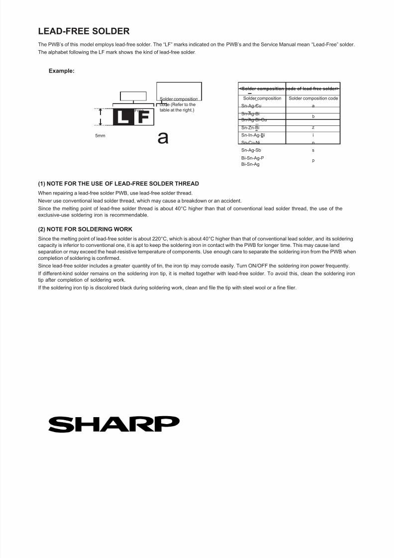
8/9/2019 AR-M318 SM
http://slidepdf.com/reader/full/ar-m318-sm 157/159
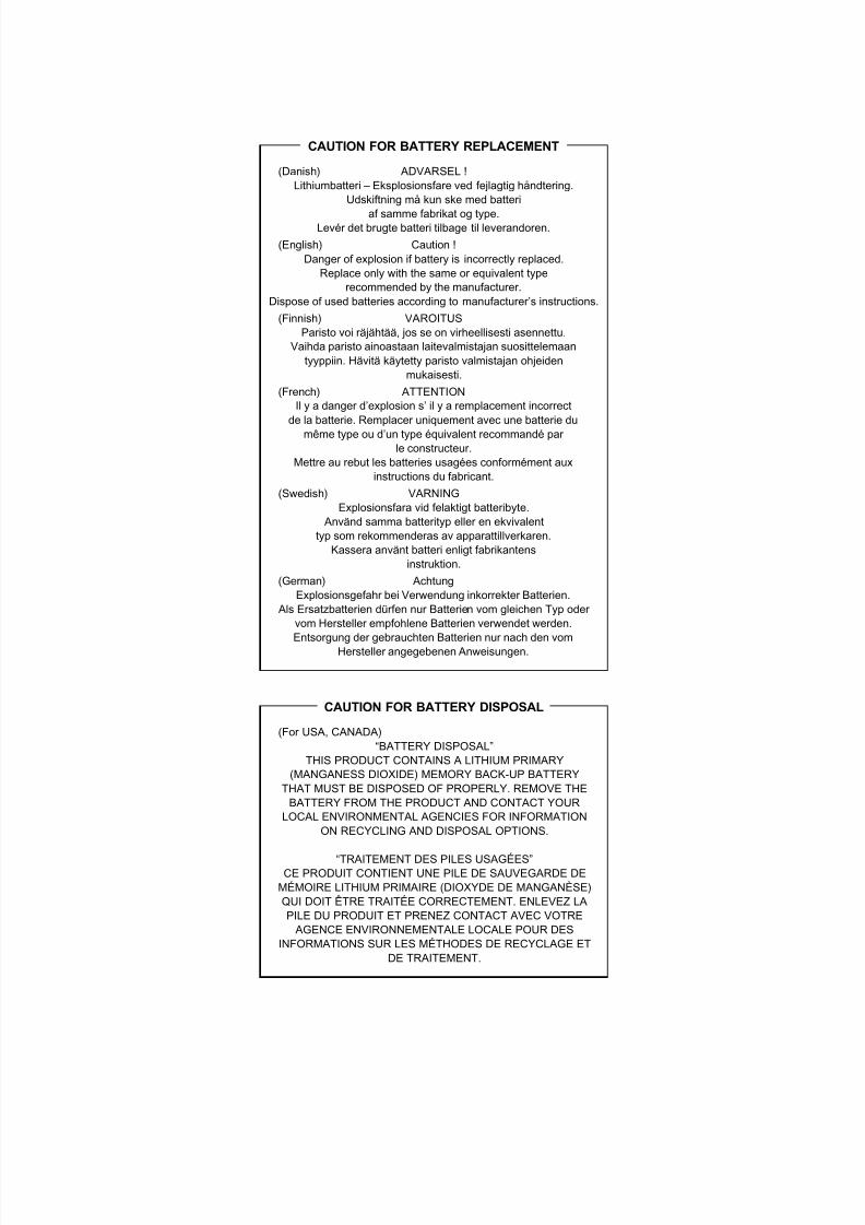
8/9/2019 AR-M318 SM
http://slidepdf.com/reader/full/ar-m318-sm 158/159
(Danish) ADVARSEL !Lithiumbatteri – Eksplosionsfare ved fejlagtig håndtering.
Udskiftning må kun ske med batteri
af samme fabrikat og type.Levér det brugte batteri tilbage til leverandoren.(English) Caution !
Danger of explosion if battery is incorrectly replaced.Replace only with the same or equivalent type
recommended by the manufacturer.Dispose of used batteries according to manufacturer’s instructions.
(Finnish) VAROITUSParisto voi räjähtää, jos se on virheellisesti asennettu.
Vaihda paristo ainoastaan laitevalmistajan suosittelemaantyyppiin. Hävitä käytetty paristo valmistajan ohjeiden
mukaisesti.(French) ATTENTION
Il y a danger d’explosion s’ il y a remplacement incorrectde la batterie. Remplacer uniquement avec une batterie du
même type ou d’un type équivalent recommandé par le constructeur.
Mettre au rebut les batteries usagées conformément auxinstructions du fabricant.
(Swedish) VARNINGExplosionsfara vid felaktigt batteribyte.
Använd samma batterityp eller en ekvivalenttyp som rekommenderas av apparattillverkaren.
Kassera använt batteri enligt fabrikantensinstruktion.
(German) AchtungExplosionsgefahr bei Verwendung inkorrekter Batterien.
Als Ersatzbatterien dürfen nur Batterien vom gleichen Typ oder vom Hersteller empfohlene Batterien verwendet werden.Entsorgung der gebrauchten Batterien nur nach den vom
Hersteller angegebenen Anweisungen.
(For USA, CANADA)“BATTERY DISPOSAL”
THIS PRODUCT CONTAINS A LITHIUM PRIMARY(MANGANESS DIOXIDE) MEMORY BACK-UP BATTERY
THAT MUST BE DISPOSED OF PROPERLY. REMOVE THEBATTERY FROM THE PRODUCT AND CONTACT YOUR
LOCAL ENVIRONMENTAL AGENCIES FOR INFORMATIONON RECYCLING AND DISPOSAL OPTIONS.
“TRAITEMENT DES PILES USAGÉES”CE PRODUIT CONTIENT UNE PILE DE SAUVEGARDE DE
MÉMOIRE LITHIUM PRIMAIRE (DIOXYDE DE MANGANÈSE)QUI DOIT ÊTRE TRAITÉE CORRECTEMENT. ENLEVEZ LAPILE DU PRODUIT ET PRENEZ CONTACT AVEC VOTRE AGENCE ENVIRONNEMENTALE LOCALE POUR DES
INFORMATIONS SUR LES MÉTHODES DE RECYCLAGE ETDE TRAITEMENT.
CAUTION FOR BATTERY REPLACEMENT
CAUTION FOR BATTERY DISPOSAL

8/9/2019 AR-M318 SM
http://slidepdf.com/reader/full/ar-m318-sm 159/159
All rights reserved.Printed in Japan.
COPYRIGHT © 2007 BY SHARP CORPORATION