Embed Size (px)
Citation preview
- 1 -
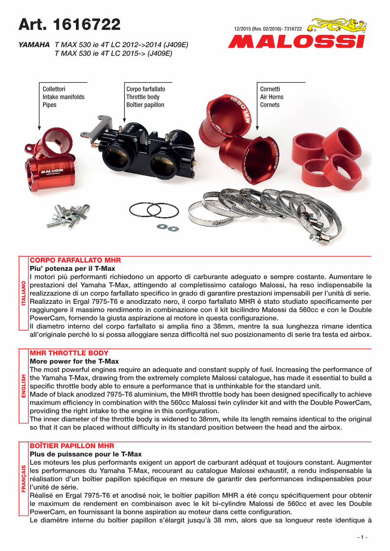
CollettoriIntake manifoldsPipes
CornettiAir HornsCornets
Corpo farfallatoThrottle bodyBoîtier papillon
CORPO FARFALLATO MHRPiu’ potenza per il T-MaxI motori più performanti richiedono un apporto di carburante adeguato e sempre costante. Aumentare le prestazioni del Yamaha T-Max, attingendo al completissimo catalogo Malossi, ha reso indispensabile la realizzazione di un corpo farfallato specifi co in grado di garantire prestazioni impensabili per l’unità di serie.Realizzato in Ergal 7975-T6 e anodizzato nero, il corpo farfallato MHR é stato studiato specifi camente per raggiungere il massimo rendimento in combinazione con il kit bicilindro Malossi da 560cc e con le Double PowerCam, fornendo la giusta aspirazione al motore in questa confi gurazione.Il diametro interno del corpo farfallato si amplia fi no a 38mm, mentre la sua lunghezza rimane identica all’originale perché lo si possa alloggiare senza diffi coltà nel suo posizionamento di serie tra testa ed airbox.
MHR THROTTLE BODYMore power for the T-MaxThe most powerful engines require an adequate and constant supply of fuel. Increasing the performance of the Yamaha T-Max, drawing from the extremely complete Malossi catalogue, has made it essential to build a specifi c throttle body able to ensure a performance that is unthinkable for the standard unit.Made of black anodized 7975-T6 aluminium, the MHR throttle body has been designed specifi cally to achieve maximum effi ciency in combination with the 560cc Malossi twin cylinder kit and with the Double PowerCam, providing the right intake to the engine in this confi guration.The inner diameter of the throttle body is widened to 38mm, while its length remains identical to the original so that it can be placed without diffi culty in its standard position between the head and the airbox.
BOÎTIER PAPILLON MHRPlus de puissance pour le T-MaxLes moteurs les plus performants exigent un apport de carburant adéquat et toujours constant. Augmenter les performances du Yamaha T-Max, recourant au catalogue Malossi exhaustif, a rendu indispensable la réalisation d’un boîtier papillon spécifi que en mesure de garantir des performances indispensables pour l’unité de série.Réalisé en Ergal 7975-T6 et anodisé noir, le boîtier papillon MHR a été conçu spécifi quement pour obtenir le maximum de rendement en combinaison avec le kit bi-cylindre Malossi de 560cc et avec les Double PowerCam, en fournissant la bonne aspiration au moteur dans cette confi guration.Le diamètre interne du boîtier papillon s’élargit jusqu’à 38 mm, alors que sa longueur reste identique à
Art. 1616722 YAMAHA T MAX 530 ie 4T LC 2012->2014 (J409E) T MAX 530 ie 4T LC 2015-> (J409E)
ITA
LIA
NO
EN
GLIS
HFR
AN
ÇA
IS12/2015 (Rev. 02/2016)- 7316722
- 2 -
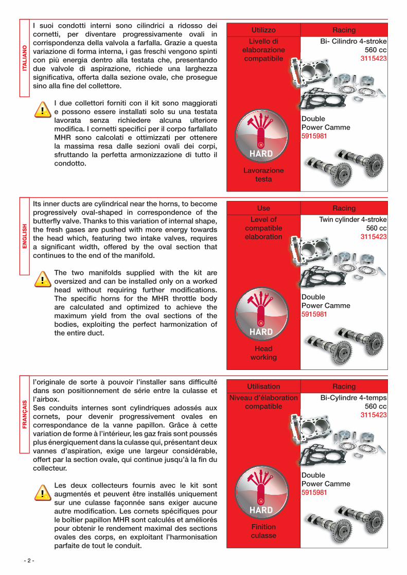
I suoi condotti interni sono cilindrici a ridosso dei cornetti, per diventare progressivamente ovali in corrispondenza della valvola a farfalla. Grazie a questa variazione di forma interna, i gas freschi vengono spinti con più energia dentro alla testata che, presentando due valvole di aspirazione, richiede una larghezza signifi cativa, offerta dalla sezione ovale, che prosegue sino alla fi ne del collettore.
I due collettori forniti con il kit sono maggiorati e possono essere installati solo su una testata lavorata senza richiedere alcuna ulteriore modifi ca. I cornetti specifi ci per il corpo farfallato MHR sono calcolati e ottimizzati per ottenere la massima resa dalle sezioni ovali dei corpi, sfruttando la perfetta armonizzazione di tutto il condotto.
Its inner ducts are cylindrical near the horns, to become progressively oval-shaped in correspondence of the butterfl y valve. Thanks to this variation of internal shape, the fresh gases are pushed with more energy towards the head which, featuring two intake valves, requires a signifi cant width, offered by the oval section that continues to the end of the manifold.
The two manifolds supplied with the kit are oversized and can be installed only on a worked head without requiring further modifi cations. The specifi c horns for the MHR throttle body are calculated and optimized to achieve the maximum yield from the oval sections of the bodies, exploiting the perfect harmonization of the entire duct.
l’originale de sorte à pouvoir l’installer sans diffi culté dans son positionnement de série entre la culasse et l’airbox.Ses conduits internes sont cylindriques adossés aux cornets, pour devenir progressivement ovales en correspondance de la vanne papillon. Grâce à cette variation de forme à l’intérieur, les gaz frais sont poussés plus énergiquement dans la culasse qui, présentant deux vannes d’aspiration, exige une largeur considérable, offert par la section ovale, qui continue jusqu’à la fi n du collecteur.
Les deux collecteurs fournis avec le kit sont augmentés et peuvent être installés uniquement sur une culasse façonnée sans exiger aucune autre modifi cation. Les cornets spécifi ques pour le boîtier papillon MHR sont calculés et améliorés pour obtenir le rendement maximal des sections ovales des corps, en exploitant l’harmonisation parfaite de tout le conduit.
ITA
LIA
NO
EN
GLIS
HFR
AN
ÇA
ISUtilizzo Racing
Livello di elaborazione compatibile
Lavorazionetesta
Bi- Cilindro 4-stroke560 cc
3115423
DoublePower Camme5915981
3115423
Use Racing
Level ofcompatibleelaboration
Headworking
Twin cylinder 4-stroke560 cc
3115423
DoublePower Camme5915981
3115423
Utilisation Racing
Niveau d’élaborationcompatible
Finitionculasse
Bi-Cylindre 4-temps560 cc
3115423
DoublePower Camme5915981
3115423
- 3 -
NB: al fi ne di ottenere le migliori prestazioni è necessario installare il corpo farfallato lavorando preventivamente la testata originale, utilizzando il collettore per allargare il diametro del condotto (cercando di ottenere un condotto il più uniforme possibile)
Per valorizzare appieno questo prodotto si consiglia l’abbinamento con motori equipaggiati con il kit bicilindro Malossi da 560cc e con le Double PowerCam.
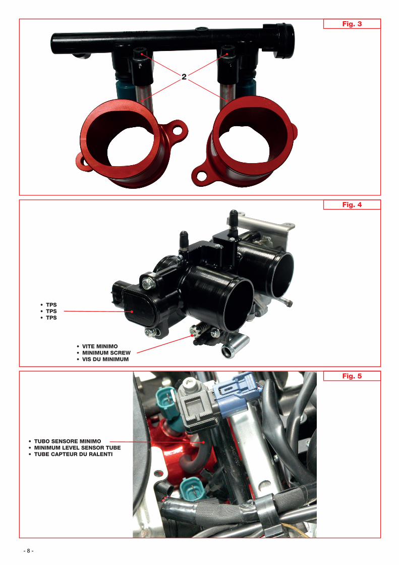
ISTRUZIONI DI MONTAGGIO• Smontare la scatola fi ltro, il corpo farfallato e i collettori originali• Smontare i seguenti componenti dal corpo farfallato originale: - TPS - Gruppo regolazione minimo - Settore comando gas - Cappuccio e tubo sensore minimo• Applicare le suddette parti al corpo farfallato Malossi (Fig. 1 - Fig. 2)• Montare il gruppo iniettori sui collettori Malossi, utilizzando viti e distanziali 2 forniti nel kit (Fig. 3)• Montare i collettori sulla testa interponendo l’oring fornito nel kit• Inserire i manicotti con le relative fascette sui collettori• Inserire il corpo farfallato su di essi
NB: in order to obtain the best performance it is necessary to install the throttle body, by machining fi rst the original head, using the manifold to increase the duct diameter (trying to obtain a pipeline as even as possible)
To fully exploit this product we recommend coupling motors equipped with two- cylinder kits from Malossi of 560cc and Double PowerCam.
ASSEMBLY INSTRUCTIONS• Remove the fi lter box, the throttle body and the original manifolds• Remove the following parts from the original throttle body: - TPS - Minimum level regulation unit - Gas control sector - Minimum level sensor tube and cap• Apply the above parts to Malossi throttle body (Fig. 1 – Fig. 2)• Install the injectors on Malossi manifolds, using screws and spacers 2 supplied in the kit (Fig. 3)• Install the manifolds on the head by interposing the O ring supplied in the kit• Fit the sleeves and their clamps on the manifolds• Insert the throttle body on the same
NB: afi n d’obtenir les meilleures performances il est nécessaire d’installer le boîtier papillon en travaillant préventivement la culasse d’origine, en utilisant le collecteur pour élargir le diamètre du conduit (en cherchant d’obtenir un conduit le plus possible uniforme)
Pour valoriser pleinement ce produit nous conseillons l’accouplement avec les moteurs équipés de kit bi-cylindre Malossi de 560cc et de Double PowerCam.
INSTRUCTIONS DE MONTAGE• Démonter le boîtier à fi ltre, le boîtier papillon et les collecteurs d’origine• Démonter les composants du boîtier papillon d’origine suivants: - TPS - Groupe réglage du ralenti - Secteur commande du gaz - Capuchon et tube capteur du ralenti• Appliquer les parties susmentionnées au boîtier papillon Malossi (Fig. 1 – Fig. 2)• Monter le groupe des injecteurs sur les collecteurs Malossi, en utilisant des vis et des entretoises 2 fournies
dans le kit (Fig. 3)• Monter les collecteurs sur la culasse en intercalant le joint torique dans le kit• Introduire les manchons avec les colliers correspondants sur les collecteurs
ITA
LIA
NO
EN
GLIS
HFR
AN
ÇA
IS
- 4 -
• NB: per poter procedere con il montaggio dei cornetti è necessario modifi care la scatola fi ltro, allargando il foro di alloggiamento dei cornetti a Ø 45
• Inserire i manicotti con le relative fascette sul corpo farfallato• Inserire la scatola fi ltro nel telaio• Inserire i cornetti all’interno della scatola fi ltro, alloggiandoli nei relativi manicotti esercitando una lieve
pressione sui cornetti• Serrare i cornetti utilizzando le fascette fornite nel kit NB: serrare le fascette tenendo le teste delle viti sfalsate• Ricollegare i connettori degli iniettori, il connettore TPS, il tubo sensore minimo• Collegare i tubi del gruppo regolazione minimo • Agganciare i cavi al settore comando gas
• NB: in order to proceed with the installation of the conical bushing you need to change the fi lter box, enlarging the housing bore of the conical bushings to Ø 45
• Fit the sleeves and their clamps on the throttle body• Insert the fi lter box in the frame• Fit the conical bushings onto the dedicated sleeves inside the fi lter box, exerting a slight pressure.• Tighten the conical bushings using the clamps supplied in the kit Note: tighten the clamps and leave the screw heads staggered• Reconnect the connectors of the injectors, the TPS connector, the minimum level sensor tube• Connect the minimum level adjustment unit pipes • Hook the cables to gas control sector
• Introduire le boîtier papillon sur ces derniers• NB: pour pouvoir monter les cornets il faut modifi er le boîtier à fi ltre, en élargissant le trou de
logement des cornets à 45 Ø• Introduire les manchons avec les colliers correspondants sur le boîtier papillon• Introduire le boîtier dans le châssis• Introduire les cornets à l’intérieur du boîtier à fi ltre, en les logeant dans les manchons relatifs en poussant
légèrement sur les cornets.• Serrer les cornets en utilisant les colliers fournis dans le kit NB: serrer les colliers en tenant les têtes des vis décalées• Brancher à nouveau les connecteurs des interrupteurs, le connecteur TPS, le tube capteur du ralenti• Brancher le tube du groupe de réglage du ralenti • Brancher les câbles au secteur commande du gaz
ITA
LIA
NO
EN
GLIS
HFR
AN
ÇA
IS
- 5 -
Taratura TPS (Fig. 4)• Entrare in modalità taratura TPS utilizzando i tasti presenti sul cruscotto.• Serrare provvisoriamente il sensore di posizione TPS.• Controllare che la manopola acceleratore sia completamente chiusa.• Collegare il sensore posizione del TPS al cablaggio elettrico.• Impostare il blocchetto accensione su “OFF” e posizionare l’interruttore arresto motore su “ ”
• Premere contemporaneamente e tenere premuti i pulsanti di impostazione sinistro e destro (1), posizionare il blocchetto accensione su “ON” e continuare a premere i pulsanti per 8 secondi o più.
NB: “dIAG” appare sul display a cristalli liquidi del totalizzatore contachilometri.
• Viene selezionato il numero codice diagnostico “d:01”• Regolare la posizione del TPS in modo tale che sul pannello strumenti possano apparire le cifre 14-20.• Ruotare il settore nelle asole ottenendo il valore corretto (visualizzato nel cruscotto).• Serrare le due viti e riverifi care che il valore sia corretto.
TPS Calibration (Fig. 4)• Access the TPS calibration mode using the buttons on the dashboard.• Temporarily tighten the position sensor TPS.• Check that the throttle grip is completely closed.• Connect the TPS position sensor to the electrical cables.• Set the ignition switch to “OFF” and set the motor stop switch to “ ”
• Simultaneously press and hold the left and right setting buttons (1), set the ON/OFF switch to “ON” and hold the buttons for 8 seconds or more.
NB: “dIAG” appears on the LCD display of the totalizer
• Select the diagnostic code number “d:01”• Adjust the position of the TPS so that the instrument panel displays the digits 14-20.• Turn he dial in the slots to get the correct value (shown on dashboard).• Tighten the two screws and check again that the value is correct.
Calibrage TPS (Fig. 4)• Entrer en modalité calibrage TPS en utilisant les touches présentes sur le tableau de bord.• Serrer provisoirement le capteur de position TPS• Contrôler que la poignée accélérateur soit complètement fermée.• Brancher le capteur de position TPS au câblage électrique.• Confi gurer le bloc de démarrage sur “OFF” et positionner l’interrupteur arrêt moteur sur “ ”
• Appuyer simultanément et maintenir appuyés les boutons de confi guration gauche et droit (1), positionner le bloc de démarrage sur “ON” et continuer à appuyer sur les boutons 8 ou plus secondes.
NB: “dIAG” apparaît sur l’affi cheur à cristaux liquides du totaliseur du compteur kilométrique.
• Le numéro code diagnostique est sélectionné “d:01”• Régler la position du TPS de manière à ce que sur le panneau instruments puissent apparaître les chiffres
14-20.• Tourner le sélecteur dans les fentes en obtenant la valeur correcte (visualisée dans le tableau de bord).• Serrer les deux vis et vérifi er à nouveau que la valeur soit correcte.
ITA
LIA
NO
EN
GLIS
HFR
AN
ÇA
IS
2040
60
80100 140120
160
180
km/h9
x1000/min8
765
4
32 1 0
1
2040
60
80100 140120
160
180
km/h9
x1000/min8
765
4
32 1 0
1
2040
60
80100 140120
160
180
km/h9
x1000/min8
765
4
32 1 0
1
- 6 -
• Il corpo farfallato ha la battuta del minimo regolata in fabbrica. Se non si riuscisse ad ottenere la giusta regolazione servendosi della vite minimo, procedere con la
regolazione come indicato nel paragrafo seguente. NB: è preferibile restare il più vicino possibile al valore minimo.
Regolazione minimo (Fig. 4)• Avvitare fi no a battuta la vite regolazione minimo e svitarla di 4,5 giri.• Servendosi della battuta di fi ne corsa 1 (Fig. 1) portare il regime motore a 1.200/1.400 RPM.
Attenzione:variando la battuta del minimo sarà necessario ritarare il TPS.
• The throttle body has the minimum threshold stop set by the factory. If you fail to get the right setting by turning the minimum level screws, proceed with the adjustment as
indicated in the following section. NB: it is better to have a value as close as possible to the minimum value.
Minimum level adjustment (Fig. 4)• Fully tighten the minimum level screw and unscrew it by 4.5 turns.• Use the limit switch 1 (Fig. 1) and set the engine speed to 1,200/1,400 RPM.
Important:by varying the minimum level stop you will need to reset the TPS.
• Le boîtier papillon a la butée du ralenti réglée à l’usine. Si on n’arriverait pas à obtenir le bon réglage en se servant de la vis du minimum, procéder avec le réglage
comme indiqué dans le paragraphe suivant. NB: il est préférable de rester le plus proche possible à la valeur minimale.
Réglage du ralenti (Fig. 4)• Visser jusqu’à la butée la vis du réglage du ralenti et la dévisser de 4-5 tours.• En se servant de la butée de fi n de course 1 (Fig. 1) mettre le moteur au ralenti à 1.200/1.400 RPM.
Attention:en changeant la butée du ralenti il sera nécessaire de calibrer à nouveau le TPS.
ITA
LIA
NO
EN
GLIS
HFR
AN
ÇA
IS
- 7 -
Fig. 2
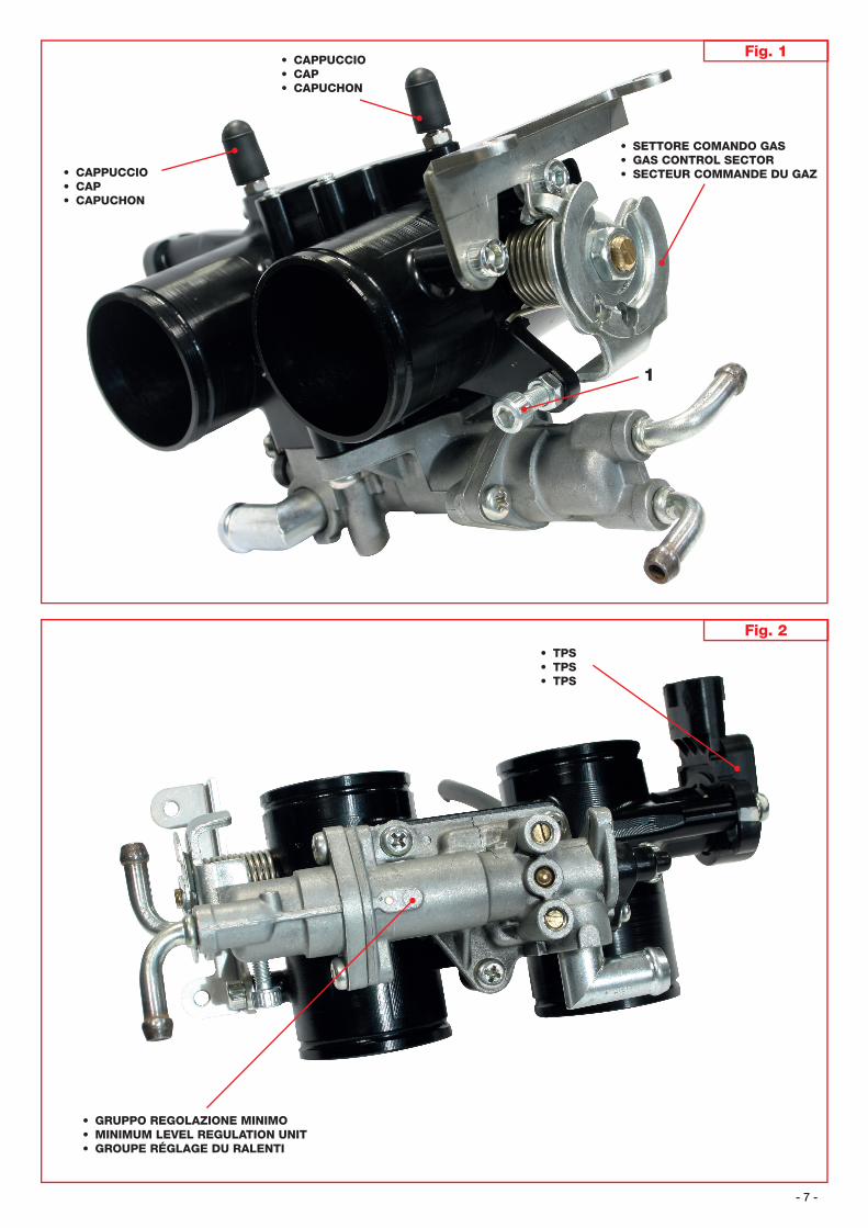
• GRUPPO REGOLAZIONE MINIMO• MINIMUM LEVEL REGULATION UNIT• GROUPE RÉGLAGE DU RALENTI
• TPS• TPS• TPS
• CAPPUCCIO• CAP• CAPUCHON
Fig. 1
• SETTORE COMANDO GAS• GAS CONTROL SECTOR• SECTEUR COMMANDE DU GAZ
1
• CAPPUCCIO• CAP• CAPUCHON
- 8 -
Fig. 3
Fig. 4
• VITE MINIMO• MINIMUM SCREW• VIS DU MINIMUM
• TPS• TPS• TPS
Fig. 5
• TUBO SENSORE MINIMO• MINIMUM LEVEL SENSOR TUBE• TUBE CAPTEUR DU RALENTI
2