Embed Size (px)
Citation preview

123
REFLUX VALVE
CALSENS
GR
AP
HIQ
UE
IN
TER
NA
TIO
NA
L, M
AY
201
4 (1
000)
DUAL PLATE CHECK VALVE FOOT VALVE
DUAL PLATE WAFER TYPE CHECK VALVE DOUBLE FLANGED DUAL PLATE CHECK VALVE
MATERIAL Manufacturing Standard - API-594, Flanged ends as per ANSI B16.5 or Customers’ Requirements.
By-Pass Arrangement also available. Testing Standard - API-598.
For horizontal flow application. Valve must be installed with the disc hinge pin in the vertical position to ensure proper operation.
Upto 150 mm valve plate can be leaded tin bronze.
MATERIALS & CONSTRUCTION
1. Pin Retainer Stainless Steel
2. Disc Seal Rubber / S.S. / L.T.B.
3. Body Ring Rubber / S.S. / L.T.B.
4. Springs Stainless Steel
5. Valve Plate C.I./D.I./CS
6. Stop Pin Stainless Steel
7. Hinge Pin Stainless Steel
8. Body C.I./D.I./CS
DIMENSIONS FOR DUAL PLATE CHECK VALVES
1 2 3 4 5 6 7 8 9 11 12 13 14 15 16 17 18 19
NB/Size 50 65 80 100 125 150 200 250 300 350 400 450 500 600 750 900 1050 1200
Class 125 (L) 54 60 67 67 83 95 127 140 181 184 191 203 213 222 305 368 432 524
Class 150 (L) 54 60 67 67 83 95 127 140 181 222 232 264 292 318 368 483 568 629
CALSENS FOOT VALVES WITH STRAINERSFor vertical suction pipelines best quality accessories are required in efficient pumping plants for unrestricted flow of water and minimum friction. Sound design, excellent workmanship and large strainer are of Calsens Foot Valves retain water in pump and suction pipes and stop any foreign body penetrating the pump through suction pipes.STANDARDS1. IS-4038-1967 – 25 mm. to 450 mm.2. Similar to G & K cat. Fig – H 35 A-32 mm. To 900 mm.
H 38-32 mm. To 600 mm.MATERIALS & CONSTRUCTION1. Body, Disc. Flap & Lift Guide – Grey Cast Iron conforming to IS
210/Gr. - FG 20.2. Ring – Leaded tin bronze (Rings of Cast
Iron, AISI 410 SS Leather, Rubber can be supplied on demand).
3. End Connections – Flanged type/Screwed types.4. Flanges – Faced & Drilled to IS 1538/1993
BS. 10 Table D/E. On demand drilling asper DIN/ANS/undrilled possible.
5. Strainer – Grey Cast Iron/Mild Steel.
DIMENSIONS FOR FOOT VALVES(All dimensions ae in mm. Unless stated otherwise)
Size Fig. 25 32 40 50 65 80 100 125 150 200 225 250 300 350 400 450
Fig. 1
A 120 140 150 160 220 240 290 340 380 – – – – – – –
B 90 105 105 124 146 190 248 330 325 – – – – – – –
C 12 14 14 16 20 22 26 26 26 – – – – – – –
D 12 14 14 16 20 22 26 26 26 – – – – – – –
Fig. 2A – – – 200 200 225 270 294 375 580 – – – – – –
B – – – 250 263 275 350 394 450 675 – – – – – –
Fig. 3A – – – 200 200 225 270 294 375 580 580 740 740 880 880 880
B – – – 200 362 275 350 394 450 645 645 750 750 1000 1115 1115
CALSENS PRIVATE LIMITEDAn ISO 9001 : 2008 Registered Firm6/1A, British Indian Street, Kolkata 700 069 Phone : 2248 6527, 3293 8984, Fax : 91 33 2210 4154 e-mail : [email protected], Website : www.calsens.com Offices/Dealers at : Chennai Bhubaneshwar Mumbai Pune Hyderabad Rourkela Ranchi Surat New Delhi
Fig. 1 Fig. 2 Fig. 3
TECHNICAL DATA SHEETS

1 2 3
CALSENS Reflux/Check/Non-return Valves are now a name to reckcon among engineers trough out the country. Each Valve is specially tested under strict supervision and quality control. Design, production and hard gained field experience have made these valves reliable. Maximum utility is provided by these valves in Irrigation, River Control Installations, Industrial Plants and Projects, Cooling Towers and in the works of Public Health Projects etc.CALSENS guarantees a trouble-free service for years for their valves.
APPLICATIONSCalsens Reflux/Check/Non-return valves are designed to provide air and water cushioning to prevent water hammer and also to prevent backflow of water from rising mains. Valves suitable for handling clear water having turbidity of 5000 ppm maximum within the limits of the working pressure. Suitable for temperature upto 600C. Hinge Pin construction of a special type can also be arranged.
STANDARDS1. IS 5312 (Part-1) 2004-50 mm to 600 mm2. IS 5312 (Part-2) 1986-500 mm to 1200 mm3. Similar to G & K cat. Fig. M-1 600 mm to 750 mm
(Single door)4. Similar to G & K cat. Fig. - M-8 600 mm & above
(Multi door)
MATERIALS & CONSTRUCTION1. Body, Door, Cover, Hinge – Grey Cast Iron, conforming to
IS 210 Gr. FG 200.2. Hinge Pin – AISI 410 – Stainless Steel
High Tensil Brass to IS : 320 HT2
3. Body Ring/Door Ring – Leaded tin bronze/ss.4. Door Faces – Natural/Synthetic rubber
(Optional)5. Hinge Plug & Air Plug – SS IS : 66036. Flanges – Faced & Drilled to IS :
1538/93 BSS-10, Table D/E. (One demand drilling as per
DIN/ANSI/undrilled possible). 7. Bolts & Nuts – Carbon Steel IS : 1363
ACCESSORIES(Following accessories can be supplied)
1. By-Pass Arrangement. 2. Dashpot Arrangement. 3. Counter Weight Arrangement.
WAFER CHECK VALVES
Dashpot ArrangementDashpot Arrangement is provided to control the closing time of the door and to reduce Mechanical and Hydraulic shocks to sudden closure of doors.
By-Pass ArrangementBy-Pass Arrangement is provided to reduce the unbalanced load/to supply Water for priming.
Counter Weight ArrangementIs Provided to minimise the slam on closure. The door hinge pin shall extend through a sealing gland and fitted with an external lever to permit back Flushing.
MULTI DOOR REFLUX VALVESReflux valves are generally used on rising mains as they permit water to flow in one direction only and check all the return flows. These are operated by pressure alone, having no external means of control. In large diameter pipes, the door in single door pattern would close slowly and reverse flow would cause water hammer due to surge. Therefore, multi-door pattern in resorted to, in such cases, so as to reduce the time required for closure. The flow may be controlled by means of flaps swinging up and down with pressures on to seats (swing check).
TEST & WORKING PRESSUENOMINAL
BORE PCD ODF/F L
SIZE OF BY-PASS
HINGE PIN DIA
50 125 165 203 10 10
65 145 185 216 10 10
80 160 200 241 10 10
100 180 220 292 10 12
125 210 250 330 15 12
150 240 285 356 15 16
200 295 340 495 25 20
250 350 395 622 25 22
300 400 445 698 40 25
350 460 505 787 40 25
400 515 565 914 40 32
450 565 615 978 50 32
500 565 670 978 50 38
600 725 780 1295 65 38
DIMENSIONS FOR MULTI DOOR REFLUX VALVESNominal Bore 500 600 700 750 800 900 1000 1100 1200
Length over Flanges (A) 815 914 1000 1045 1118 1250 1250 1396 1500
Overall Height (B) 1150 1333 1446 1446 1570 1634 1730 2089 2250
Height of centre from duckfoot (C) 600 685 750 750 815 850 915 1080 1175
Size of / duck Foot / (EXF)200 X250
254 X254
300 X375
300 X375
300 X375
300 X375
300 X375
400 X450
400 X450
TEST & WORKING PRESSURE Hydraulic Test Pressure in MPa
Size (mm)
Body Seat PN RatingTest Duration
Body Seat
(Single door)
50 – 600
50 – 6002.4
1.5
1.6
1.0
1.6
1.0
5
5
2
2
(Multi door)
500 – 1200
0.9
1.5
0.6
1.0
0.6
1.0
5
5
2
2
1 MPa - 10 Kg/Cm2
FLOW CAPACITIES
Valve Size mm
Normal (3 m/s)
1/s
Maximum (4 m/s)
1/s
50 6 7
80 14 17100 25 30125 39 47150 56 68175 76 91200 99 117250 167 186300 222 268350 303 367400 395 477450 502 602500 619 740600 895 1083
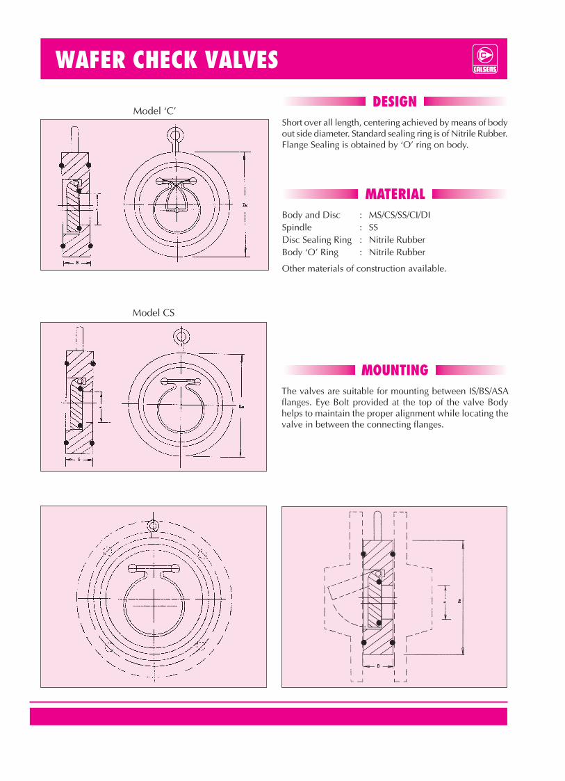
MATERIALBody and Disc : MS/CS/SS/CI/DISpindle : SSDisc Sealing Ring : Nitrile RubberBody ‘O’ Ring : Nitrile Rubber
Other materials of construction available.
DESIGNShort over all length, centering achieved by means of body out side diameter. Standard sealing ring is of Nitrile Rubber. Flange Sealing is obtained by ‘O’ ring on body.
Model ‘C’
MOUNTINGThe valves are suitable for mounting between IS/BS/ASA flanges. Eye Bolt provided at the top of the valve Body helps to maintain the proper alignment while locating the valve in between the connecting flanges.
Model CS

1 2 3
CALSENS Reflux/Check/Non-return Valves are now a name to reckcon among engineers trough out the country. Each Valve is specially tested under strict supervision and quality control. Design, production and hard gained field experience have made these valves reliable. Maximum utility is provided by these valves in Irrigation, River Control Installations, Industrial Plants and Projects, Cooling Towers and in the works of Public Health Projects etc.CALSENS guarantees a trouble-free service for years for their valves.
APPLICATIONSCalsens Reflux/Check/Non-return valves are designed to provide air and water cushioning to prevent water hammer and also to prevent backflow of water from rising mains. Valves suitable for handling clear water having turbidity of 5000 ppm maximum within the limits of the working pressure. Suitable for temperature upto 600C. Hinge Pin construction of a special type can also be arranged.
STANDARDS1. IS 5312 (Part-1) 2004-50 mm to 600 mm2. IS 5312 (Part-2) 1986-500 mm to 1200 mm3. Similar to G & K cat. Fig. M-1 600 mm to 750 mm
(Single door)4. Similar to G & K cat. Fig. - M-8 600 mm & above
(Multi door)
MATERIALS & CONSTRUCTION1. Body, Door, Cover, Hinge – Grey Cast Iron, conforming to
IS 210 Gr. FG 200.2. Hinge Pin – AISI 410 – Stainless Steel
High Tensil Brass to IS : 320 HT2
3. Body Ring/Door Ring – Leaded tin bronze/ss.4. Door Faces – Natural/Synthetic rubber
(Optional)5. Hinge Plug & Air Plug – SS IS : 66036. Flanges – Faced & Drilled to IS :
1538/93 BSS-10, Table D/E. (One demand drilling as per
DIN/ANSI/undrilled possible). 7. Bolts & Nuts – Carbon Steel IS : 1363
ACCESSORIES(Following accessories can be supplied)
1. By-Pass Arrangement. 2. Dashpot Arrangement. 3. Counter Weight Arrangement.
WAFER CHECK VALVES
Dashpot ArrangementDashpot Arrangement is provided to control the closing time of the door and to reduce Mechanical and Hydraulic shocks to sudden closure of doors.
By-Pass ArrangementBy-Pass Arrangement is provided to reduce the unbalanced load/to supply Water for priming.
Counter Weight ArrangementIs Provided to minimise the slam on closure. The door hinge pin shall extend through a sealing gland and fitted with an external lever to permit back Flushing.
MULTI DOOR REFLUX VALVESReflux valves are generally used on rising mains as they permit water to flow in one direction only and check all the return flows. These are operated by pressure alone, having no external means of control. In large diameter pipes, the door in single door pattern would close slowly and reverse flow would cause water hammer due to surge. Therefore, multi-door pattern in resorted to, in such cases, so as to reduce the time required for closure. The flow may be controlled by means of flaps swinging up and down with pressures on to seats (swing check).
TEST & WORKING PRESSUENOMINAL
BORE PCD ODF/F L
SIZE OF BY-PASS
HINGE PIN DIA
50 125 165 203 10 10
65 145 185 216 10 10
80 160 200 241 10 10
100 180 220 292 10 12
125 210 250 330 15 12
150 240 285 356 15 16
200 295 340 495 25 20
250 350 395 622 25 22
300 400 445 698 40 25
350 460 505 787 40 25
400 515 565 914 40 32
450 565 615 978 50 32
500 565 670 978 50 38
600 725 780 1295 65 38
DIMENSIONS FOR MULTI DOOR REFLUX VALVESNominal Bore 500 600 700 750 800 900 1000 1100 1200
Length over Flanges (A) 815 914 1000 1045 1118 1250 1250 1396 1500
Overall Height (B) 1150 1333 1446 1446 1570 1634 1730 2089 2250
Height of centre from duckfoot (C) 600 685 750 750 815 850 915 1080 1175
Size of / duck Foot / (EXF)200 X250
254 X254
300 X375
300 X375
300 X375
300 X375
300 X375
400 X450
400 X450
TEST & WORKING PRESSURE Hydraulic Test Pressure in MPa
Size (mm)
Body Seat PN RatingTest Duration
Body Seat
(Single door)
50 – 600
50 – 6002.4
1.5
1.6
1.0
1.6
1.0
5
5
2
2
(Multi door)
500 – 1200
0.9
1.5
0.6
1.0
0.6
1.0
5
5
2
2
1 MPa - 10 Kg/Cm2
FLOW CAPACITIES
Valve Size mm
Normal (3 m/s)
1/s
Maximum (4 m/s)
1/s
50 6 7
80 14 17100 25 30125 39 47150 56 68175 76 91200 99 117250 167 186300 222 268350 303 367400 395 477450 502 602500 619 740600 895 1083
MATERIALBody and Disc : MS/CS/SS/CI/DISpindle : SSDisc Sealing Ring : Nitrile RubberBody ‘O’ Ring : Nitrile Rubber
Other materials of construction available.
DESIGNShort over all length, centering achieved by means of body out side diameter. Standard sealing ring is of Nitrile Rubber. Flange Sealing is obtained by ‘O’ ring on body.
Model ‘C’
MOUNTINGThe valves are suitable for mounting between IS/BS/ASA flanges. Eye Bolt provided at the top of the valve Body helps to maintain the proper alignment while locating the valve in between the connecting flanges.
Model CS

123
REFLUX VALVE
CALSENS
GR
AP
HIQ
UE
IN
TER
NA
TIO
NA
L, M
AY
201
4 (1
000)
DUAL PLATE CHECK VALVE FOOT VALVE
DUAL PLATE WAFER TYPE CHECK VALVE DOUBLE FLANGED DUAL PLATE CHECK VALVE
MATERIAL Manufacturing Standard - API-594, Flanged ends as per ANSI B16.5 or Customers’ Requirements.
By-Pass Arrangement also available. Testing Standard - API-598.
For horizontal flow application. Valve must be installed with the disc hinge pin in the vertical position to ensure proper operation.
Upto 150 mm valve plate can be leaded tin bronze.
MATERIALS & CONSTRUCTION
1. Pin Retainer Stainless Steel
2. Disc Seal Rubber / S.S. / L.T.B.
3. Body Ring Rubber / S.S. / L.T.B.
4. Springs Stainless Steel
5. Valve Plate C.I./D.I./CS
6. Stop Pin Stainless Steel
7. Hinge Pin Stainless Steel
8. Body C.I./D.I./CS
DIMENSIONS FOR DUAL PLATE CHECK VALVES
1 2 3 4 5 6 7 8 9 11 12 13 14 15 16 17 18 19
NB/Size 50 65 80 100 125 150 200 250 300 350 400 450 500 600 750 900 1050 1200
Class 125 (L) 54 60 67 67 83 95 127 140 181 184 191 203 213 222 305 368 432 524
Class 150 (L) 54 60 67 67 83 95 127 140 181 222 232 264 292 318 368 483 568 629
CALSENS FOOT VALVES WITH STRAINERSFor vertical suction pipelines best quality accessories are required in efficient pumping plants for unrestricted flow of water and minimum friction. Sound design, excellent workmanship and large strainer are of Calsens Foot Valves retain water in pump and suction pipes and stop any foreign body penetrating the pump through suction pipes.STANDARDS1. IS-4038-1967 – 25 mm. to 450 mm.2. Similar to G & K cat. Fig – H 35 A-32 mm. To 900 mm.
H 38-32 mm. To 600 mm.MATERIALS & CONSTRUCTION1. Body, Disc. Flap & Lift Guide – Grey Cast Iron conforming to IS
210/Gr. - FG 20.2. Ring – Leaded tin bronze (Rings of Cast
Iron, AISI 410 SS Leather, Rubber can be supplied on demand).
3. End Connections – Flanged type/Screwed types.4. Flanges – Faced & Drilled to IS 1538/1993
BS. 10 Table D/E. On demand drilling asper DIN/ANS/undrilled possible.
5. Strainer – Grey Cast Iron/Mild Steel.
DIMENSIONS FOR FOOT VALVES(All dimensions ae in mm. Unless stated otherwise)
Size Fig. 25 32 40 50 65 80 100 125 150 200 225 250 300 350 400 450
Fig. 1
A 120 140 150 160 220 240 290 340 380 – – – – – – –
B 90 105 105 124 146 190 248 330 325 – – – – – – –
C 12 14 14 16 20 22 26 26 26 – – – – – – –
D 12 14 14 16 20 22 26 26 26 – – – – – – –
Fig. 2A – – – 200 200 225 270 294 375 580 – – – – – –
B – – – 250 263 275 350 394 450 675 – – – – – –
Fig. 3A – – – 200 200 225 270 294 375 580 580 740 740 880 880 880
B – – – 200 362 275 350 394 450 645 645 750 750 1000 1115 1115
CALSENS PRIVATE LIMITEDAn ISO 9001 : 2008 Registered Firm6/1A, British Indian Street, Kolkata 700 069 Phone : 2248 6527, 3293 8984, Fax : 91 33 2210 4154 e-mail : [email protected], Website : www.calsens.com Offices/Dealers at : Chennai Bhubaneshwar Mumbai Pune Hyderabad Rourkela Ranchi Surat New Delhi
Fig. 1 Fig. 2 Fig. 3
TECHNICAL DATA SHEETS