Embed Size (px)
Citation preview
CFD Simulation of a Lean-burn Aero-engine Combustor with Low Pollutant Emission
R. La Gala1, F. Ambrosino1 A. Funel2, S. Migliori2, P. Di Martino3, S. Colantuoni3, A. D’Anna1
1 Dipartimento di Ingegneria Chimica - Università degli Studi di Napoli Federico II, Italy 2 ENEA Agenzia Nazionale per le nuove tecnologie l’energia e lo sviluppo economico
sostenibile CR Portici - Via Vecchio Macello 80055 Portici (Napoli, Italy) 3 AVIO S.p.A. – Pomigliano d’Arco, Napoli, Italy
1. Abstract
The results of the CFD simulation of a tubular combustor for aero-engine applications developed by AVIO are presented. Simulations have been performed by using OpenFOAM. A Large-Eddy-Simulation approach is used to model turbulence; the compressible Smagorinsky model is used to describe Sub Grid Scale (SGS) motions and their interactions with the solved large-scale structures. A multi-step reaction mechanism and variable thermo-physical properties are used to model the oxidation process. The turbulence model has been also coupled with a flamelet approach for the modelling of the detailed chemistry and multiphase processes. The model has been tested for different operating conditions, for which experimental data are available. For these test cases, predicted temperatures, local fuel-air ratios and CO2 concentrations are compared with experimental data. The code has been run on CRESCO, the ENEA high power computing cluster.
2. Introduction Reduction in pollutant emissions has always been a target in the modern combustion device concept. Combustors for aero-engine applications are traditionally diffusion-flame combustors because of their performance and stability characteristics. This type of combustor usually produces high levels of pollutants (e.g. thermal NOx). The actual strict legislation for pollutant emissions has induced the aero-engine constructors to develop combustors that can respect the established limits for emissions. In the past, the most used techniques to reduce pollutant emission in aero-engine combustors were based on the injection of fuel diluents, as water and steam, employed to reduce the flame temperature. In spite of the effectiveness of these techniques, this approach determines the reduction of thermodynamic cycle efficiency, and undesirable effects such as quenching of CO burnout and mechanical corrosion of turbine blades due to impurities in the water. For this reason new concepts for combustion technology for the gas turbine industry have been introduced, particularly LPP (Lean Premixed Prevaporised) combustion, when liquid fuels are employed. This technology seems to be the most promising one for practical systems at the present time [1]. Fuel injection and mixing are critical phases to achieve efficiency in combustion in modern gas turbine engines, when they are powered by gaseous or liquid fuels. For gaseous fuels, the major concern is to obtain an optimal level of mixing among the air, fuel, and combustion products in the combustion zone. When liquid fuels are employed, they must be atomized into small droplets and then distributed in an air stream before entering the combustion zone. In addition to its primary function of preparing a combustible mixture, the fuel injector acts as a sensitive element capable of modulating the flow-field and combustion processes in a combustor. Annular, both
1
co-rotating both counter-rotating swirlers premixed injectors are adopted [2]. A short annular liner is applied in the premixed design to minimize the amount of air required for convective cooling. The combustor volume, however, is approximately twice that of a conventional diffusion combustor, to increase the residence time for complete reactions of CO and unburned hydrocarbons.
3. LES approach of the turbulence problem The study of turbulent flow inside the mixing duct of a high-pressure combustion chamber for aero-engine use needs the use of CFD (Computational Fluid Dynamics) software. The fluid flow results in turbulent motions and gradients and requires analysis by CFD to determine trends in the fields of velocity and pressure inside. A Large-Eddy-Simulation approach is used to model turbulence. The decision to directly simulate the turbulent structures belonging to the inertial range is based on the characteristics of the turbulent structures, in fact, the large scale turbulent structures have a dynamic behaviour that depends very much on the current and the direction of observation, on the contrary, small turbulent structure dynamics has an isotropic character. The Large Eddy Simulation, which provides the velocity field, averaged in space, and turbulent structures belonging to the inertial range turbulent spectrum are directly simulated, using a suitably dense grid, while the smaller grid scales of motion (or SGS i.e. Sub Grid Scale), are parameterized with a specific model. The compressible Smagorinsky model is used to describe the SGS motions and their interactions with the solved large-scale structures. In LES the "cut" between what is simulated and what is modelled depends not only on the geometry of the problem but is linked with the position of the inertial range. The closure of LES equations represents the problem of closure and is obtained with the LES turbulence models in sub-grid which should reproduce the effects of unresolved scales on those issues are resolved directly. A multi-step reaction mechanism and variable thermo-physical properties are used to model the oxidation process. The turbulence model has been also coupled with a flamelet approach for the modelling of the detailed chemistry and multiphase processes. This physical problem requires the use of commercial software, and open source availability of OpenFOAM CFD software (release 1.6), makes it preferable to other characterized by considerable licensing fees.
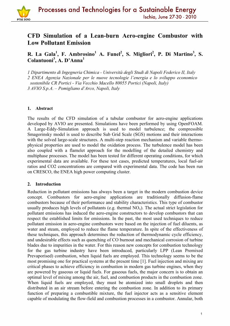
4. AVIO LPP Injector The LPP injection system developed by AVIO consists of two co-rotating radial swirlers separated by a venturi profiled wall and a converging prevaporization tube. Two principal inlets for primary and secondary air and additional holes are present for dilution air on the converging tube to reduce the risks of flash-back and to promote a secondary atomization. At the centre of the two swirlers there is an atomizer that carburets the flow that is introduced in the mixing duct. The fuel and the air are mixed in the premixing duct before entering into the combustion chamber. The injection system is welded on the water cooling tubular combustor bottom. The tubular combustor has an internal diameter of 100 mm and is 230 mm long. Figure 1 shows a scheme of the used injector.
2
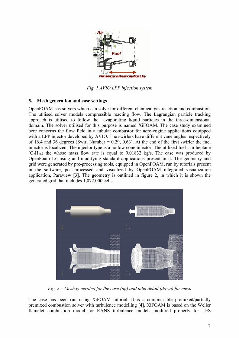
Fig. 1 AVIO LPP injection system
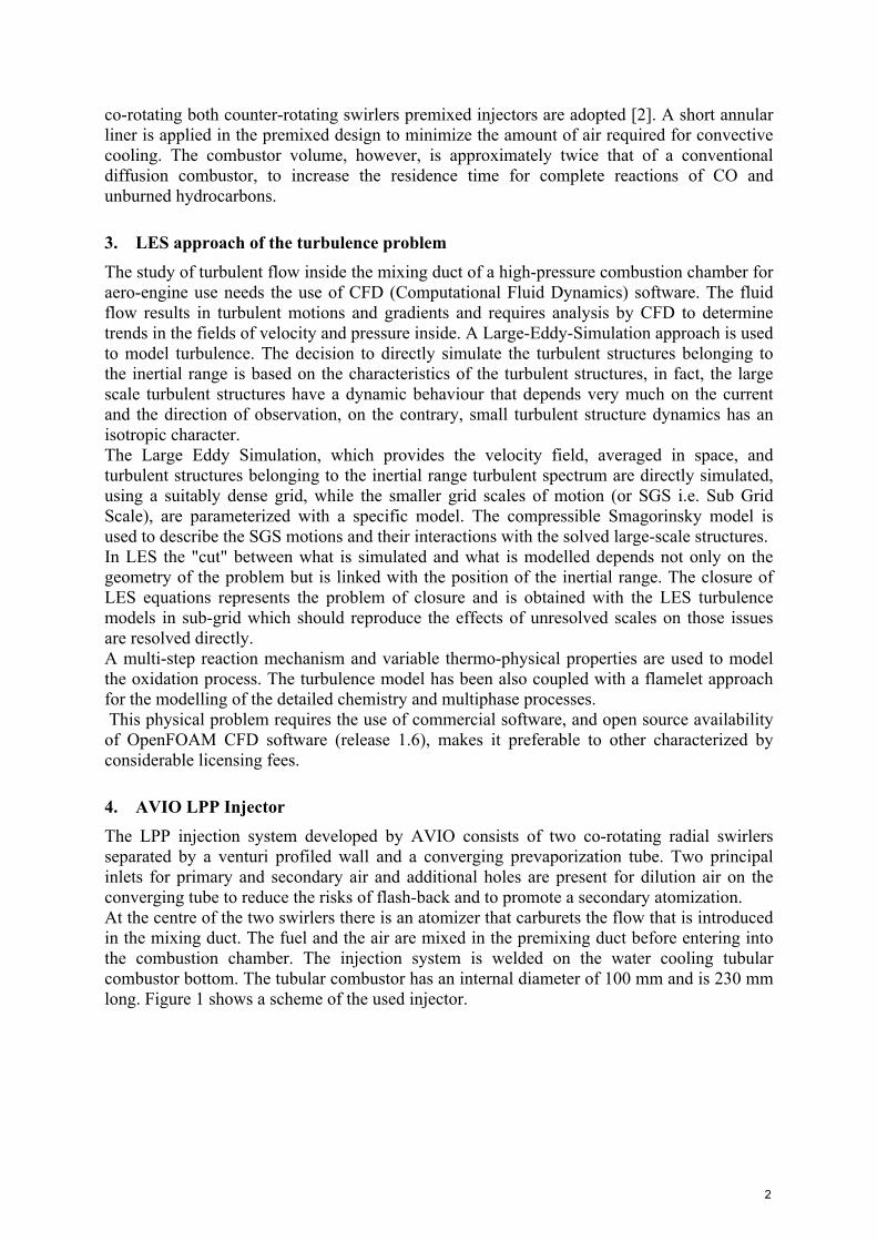
5. Mesh generation and case settings OpenFOAM has solvers which can solve for different chemical gas reaction and combustion. The utilised solver models compressible reacting flow. The Lagrangian particle tracking approach is utilised to follow the evaporating liquid particles in the three-dimensional domain. The solver utilised for this purpose is named XiFOAM. The case study examined here concerns the flow field in a tubular combustor for aero-engine applications equipped with a LPP injector developed by AVIO. The swirlers have different vane angles respectively of 16.4 and 36 degrees (Swirl Number = 0.29, 0.63). At the end of the first swirler the fuel injector is localized. The injector type is a hollow cone injector. The utilized fuel is n-heptane (C7H16) the whose mass flow rate is equal to 0.01832 kg/s. The case was produced by OpenFoam-1.6 using and modifying standard applications present in it. The geometry and grid were generated by pre-processing tools, equipped in OpenFOAM, run by tutorials present in the software, post-processed and visualized by OpenFOAM integrated visualization application, Paraview [3]. The geometry is outlined in figure 2, in which it is shown the generated grid that includes 1,072,000 cells.
Fig. 2 – Mesh generated for the case (up) and inlet detail (down) for mesh The case has been run using XiFOAM tutorial. It is a compressible premixed/partially premixed combustion solver with turbulence modelling [4]. XiFOAM is based on the Weller flamelet combustion model for RANS turbulence models modified properly for LES
3
approach. The equations of motion integrated in XiFOAM tutorials are the classical Navier-Stokes equations:
where :
;
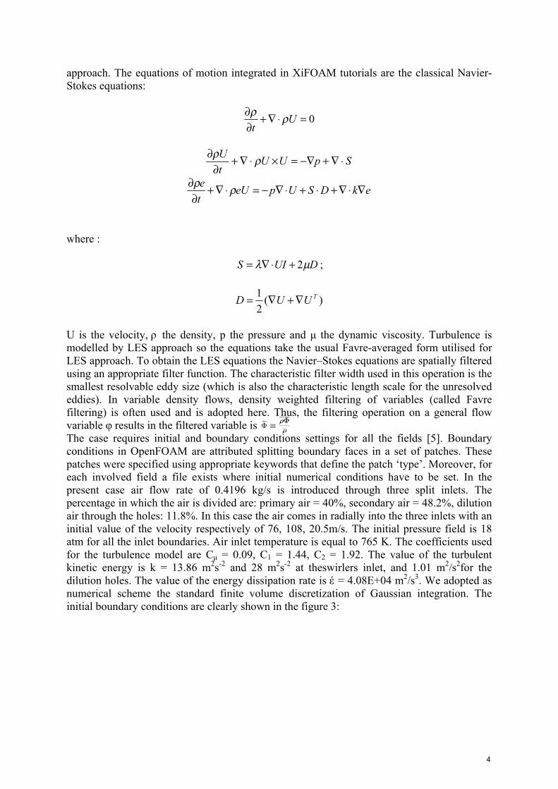
U is the velocity, ρ the density, p the pressure and µ the dynamic viscosity. Turbulence is modelled by LES approach so the equations take the usual Favre-averaged form utilised for LES approach. To obtain the LES equations the Navier–Stokes equations are spatially filtered using an appropriate filter function. The characteristic filter width used in this operation is the smallest resolvable eddy size (which is also the characteristic length scale for the unresolved eddies). In variable density flows, density weighted filtering of variables (called Favre filtering) is often used and is adopted here. Thus, the filtering operation on a general flow variable φ results in the filtered variable is The case requires initial and boundary conditions settings for all the fields [5]. Boundary conditions in OpenFOAM are attributed splitting boundary faces in a set of patches. These patches were specified using appropriate keywords that define the patch ‘type’. Moreover, for each involved field a file exists where initial numerical conditions have to be set. In the present case air flow rate of 0.4196 kg/s is introduced through three split inlets. The percentage in which the air is divided are: primary air = 40%, secondary air = 48.2%, dilution air through the holes: 11.8%. In this case the air comes in radially into the three inlets with an initial value of the velocity respectively of 76, 108, 20.5m/s. The initial pressure field is 18 atm for all the inlet boundaries. Air inlet temperature is equal to 765 K. The coefficients used for the turbulence model are Cµ = 0.09, C1 = 1.44, C2 = 1.92. The value of the turbulent kinetic energy is k = 13.86 m2s-2 and 28 m2s-2 at theswirlers inlet, and 1.01 m2/s2for the dilution holes. The value of the energy dissipation rate is έ = 4.08E+04 m2/s3. We adopted as numerical scheme the standard finite volume discretization of Gaussian integration. The initial boundary conditions are clearly shown in the figure 3:
4
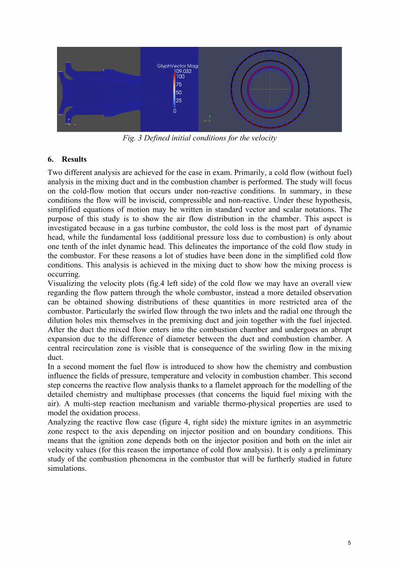
Fig. 3 Defined initial conditions for the velocity
6. Results Two different analysis are achieved for the case in exam. Primarily, a cold flow (without fuel) analysis in the mixing duct and in the combustion chamber is performed. The study will focus on the cold-flow motion that occurs under non-reactive conditions. In summary, in these conditions the flow will be inviscid, compressible and non-reactive. Under these hypothesis, simplified equations of motion may be written in standard vector and scalar notations. The purpose of this study is to show the air flow distribution in the chamber. This aspect is investigated because in a gas turbine combustor, the cold loss is the most part of dynamic head, while the fundamental loss (additional pressure loss due to combustion) is only about one tenth of the inlet dynamic head. This delineates the importance of the cold flow study in the combustor. For these reasons a lot of studies have been done in the simplified cold flow conditions. This analysis is achieved in the mixing duct to show how the mixing process is occurring. Visualizing the velocity plots (fig.4 left side) of the cold flow we may have an overall view regarding the flow pattern through the whole combustor, instead a more detailed observation can be obtained showing distributions of these quantities in more restricted area of the combustor. Particularly the swirled flow through the two inlets and the radial one through the dilution holes mix themselves in the premixing duct and join together with the fuel injected. After the duct the mixed flow enters into the combustion chamber and undergoes an abrupt expansion due to the difference of diameter between the duct and combustion chamber. A central recirculation zone is visible that is consequence of the swirling flow in the mixing duct. In a second moment the fuel flow is introduced to show how the chemistry and combustion influence the fields of pressure, temperature and velocity in combustion chamber. This second step concerns the reactive flow analysis thanks to a flamelet approach for the modelling of the detailed chemistry and multiphase processes (that concerns the liquid fuel mixing with the air). A multi-step reaction mechanism and variable thermo-physical properties are used to model the oxidation process. Analyzing the reactive flow case (figure 4, right side) the mixture ignites in an asymmetric zone respect to the axis depending on injector position and on boundary conditions. This means that the ignition zone depends both on the injector position and both on the inlet air velocity values (for this reason the importance of cold flow analysis). It is only a preliminary study of the combustion phenomena in the combustor that will be furtherly studied in future simulations.
5
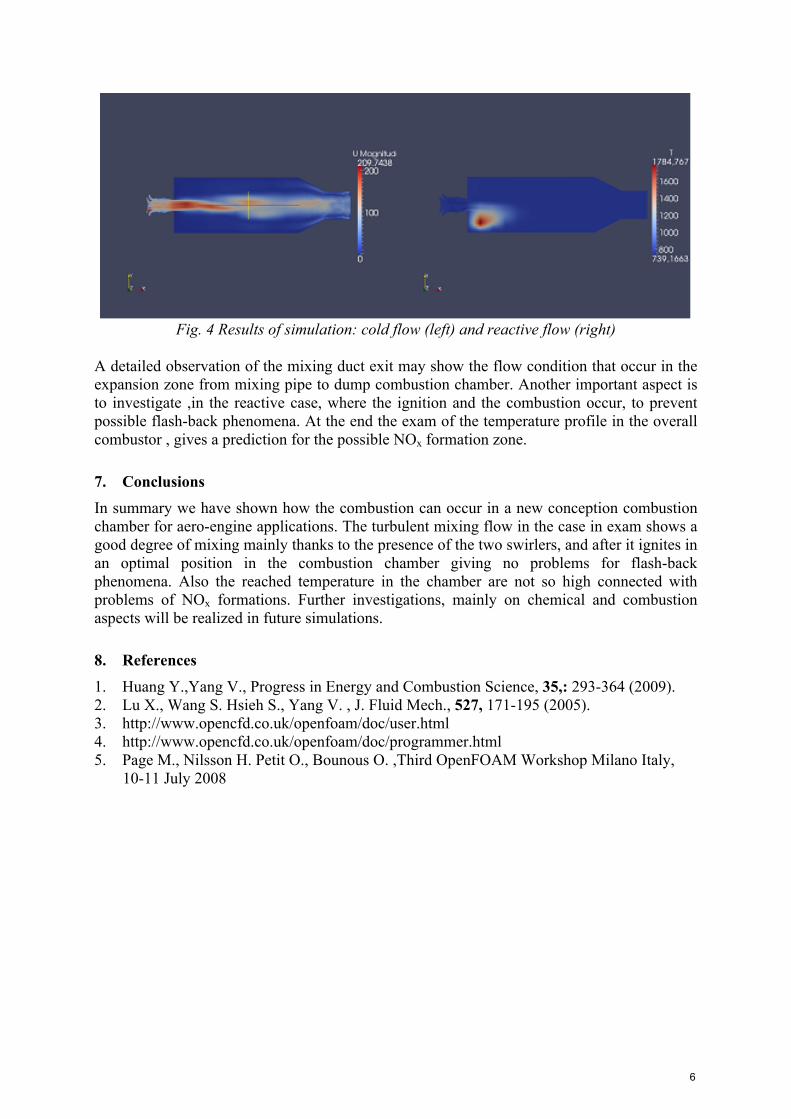
Fig. 4 Results of simulation: cold flow (left) and reactive flow (right) A detailed observation of the mixing duct exit may show the flow condition that occur in the expansion zone from mixing pipe to dump combustion chamber. Another important aspect is to investigate ,in the reactive case, where the ignition and the combustion occur, to prevent possible flash-back phenomena. At the end the exam of the temperature profile in the overall combustor , gives a prediction for the possible NOx formation zone.
7. Conclusions In summary we have shown how the combustion can occur in a new conception combustion chamber for aero-engine applications. The turbulent mixing flow in the case in exam shows a good degree of mixing mainly thanks to the presence of the two swirlers, and after it ignites in an optimal position in the combustion chamber giving no problems for flash-back phenomena. Also the reached temperature in the chamber are not so high connected with problems of NOx formations. Further investigations, mainly on chemical and combustion aspects will be realized in future simulations.
8. References 1. Huang Y.,Yang V., Progress in Energy and Combustion Science, 35,: 293-364 (2009). 2. Lu X., Wang S. Hsieh S., Yang V. , J. Fluid Mech., 527, 171-195 (2005). 3. http://www.opencfd.co.uk/openfoam/doc/user.html 4. http://www.opencfd.co.uk/openfoam/doc/programmer.html 5. Page M., Nilsson H. Petit O., Bounous O. ,Third OpenFOAM Workshop Milano Italy,
10-11 July 2008
6