Embed Size (px)
Citation preview
Dim
ens
ionn
ement
méca
niqu
e d
es
turb
omaré
act
eur
s
Introduction au dimensionnement
mécanique et dynamique des
turboréacteurs
Reference :
AERO0015-1 - MECHANICAL DESIGN OF TURBOMACHINERY -
5 ECTS - J.-C. GOLINVAL
Cours de conception aéronautique
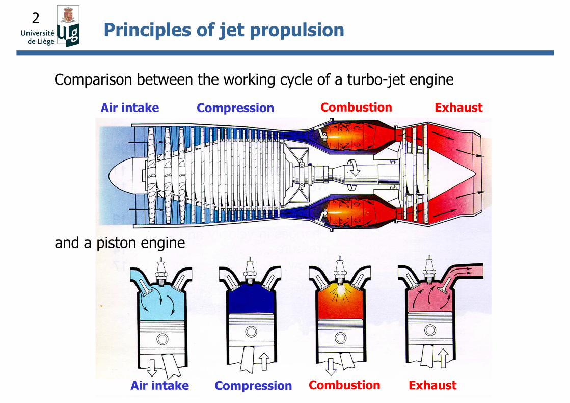
2Principles of jet propulsion
Comparison between the working cycle of a turbo-jet engine
and a piston engine
Air intake Compression Combustion Exhaust
Air intake Compression Combustion Exhaust
3
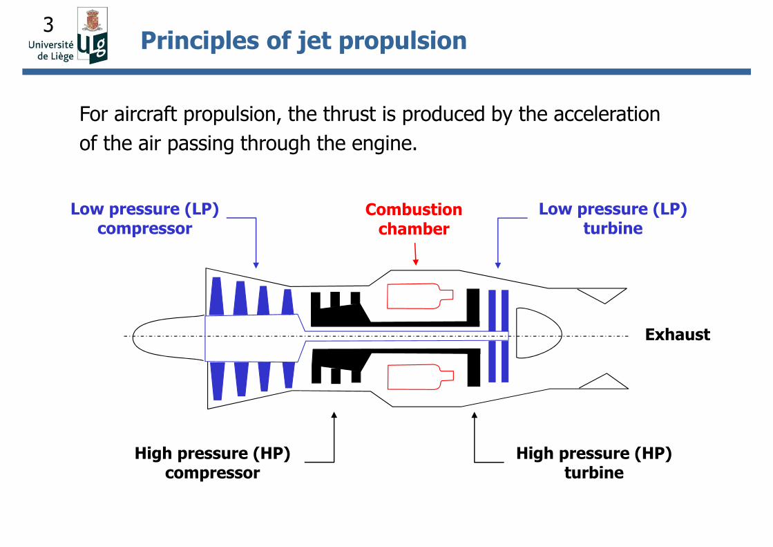
High pressure (HP) turbine
Low pressure (LP) turbine
Low pressure (LP) compressor
Combustion chamber
Exhaust
High pressure (HP) compressor
Principles of jet propulsion
For aircraft propulsion, the thrust is produced by the acceleration
of the air passing through the engine.
4
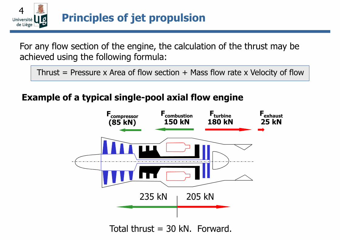
Fcompressor
(85 kN)Fcombustion
150 kN
Total thrust = 30 kN. Forward.
Fturbine
180 kNFexhaust
25 kN
235 kN 205 kN
For any flow section of the engine, the calculation of the thrust may be achieved using the following formula:
Thrust = Pressure x Area of flow section + Mass flow rate x Velocity of flow
Example of a typical single-pool axial flow engine
Principles of jet propulsion
5
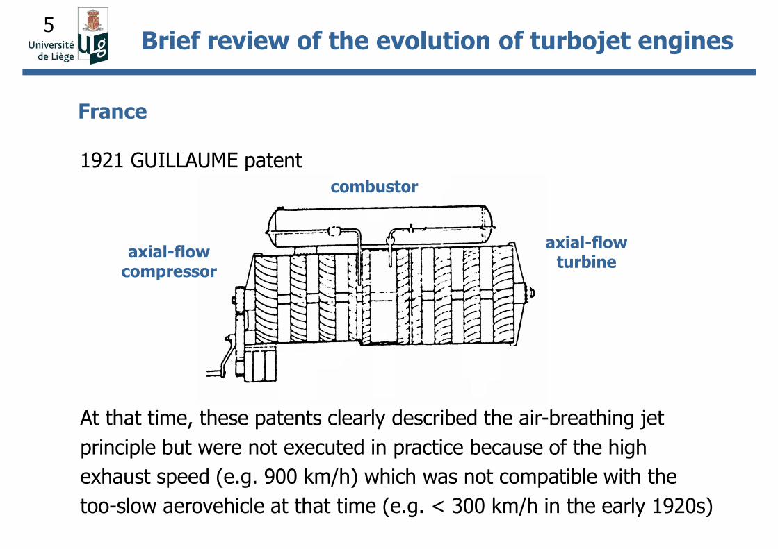
1921 GUILLAUME patent
France
axial-flow compressor
combustor
axial-flow turbine
At that time, these patents clearly described the air-breathing jet
principle but were not executed in practice because of the high
exhaust speed (e.g. 900 km/h) which was not compatible with the
too-slow aerovehicle at that time (e.g. < 300 km/h in the early 1920s)
Brief review of the evolution of turbojet engines
6
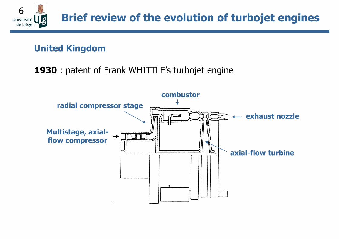
United Kingdom
1930 : patent of Frank WHITTLE’s turbojet engine
Brief review of the evolution of turbojet engines
Multistage, axial-flow compressor
radial compressor stage
combustor
axial-flow turbine
exhaust nozzle
7
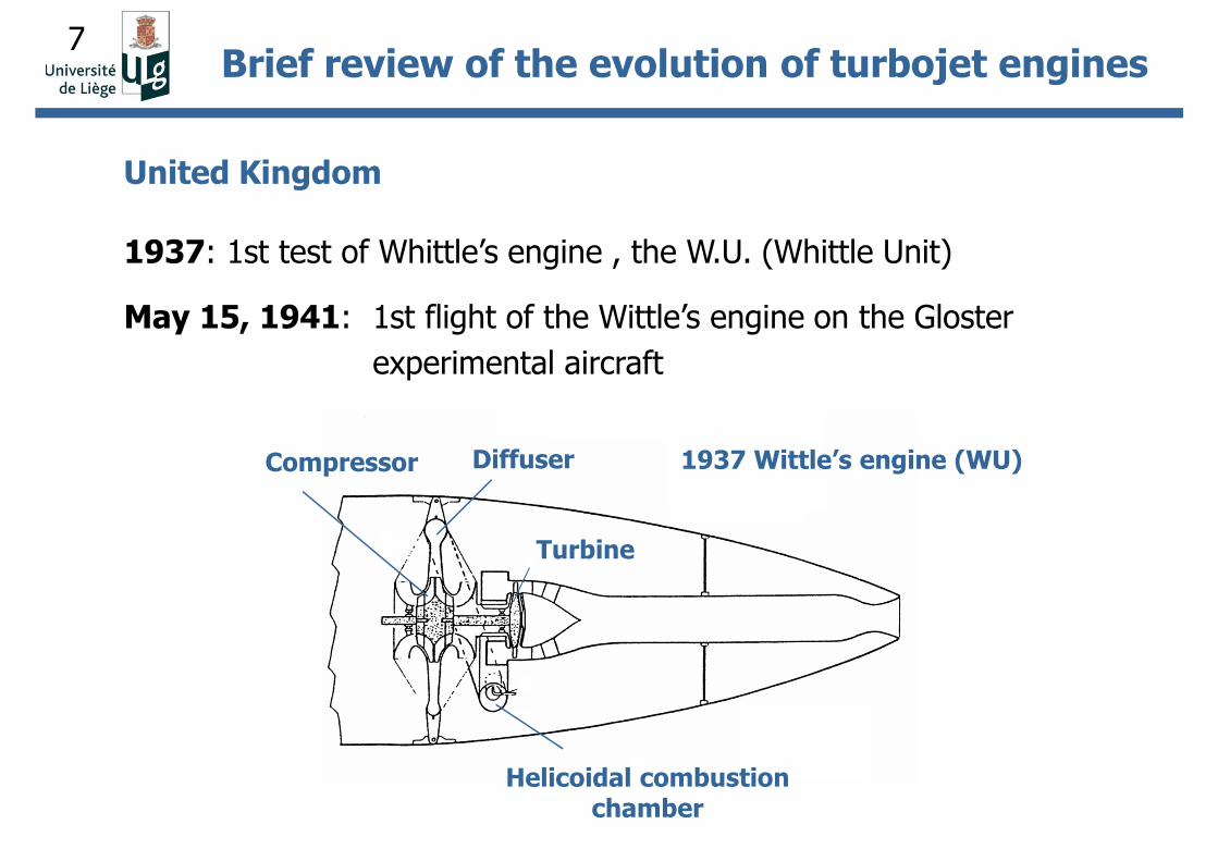
United Kingdom
1937: 1st test of Whittle’s engine , the W.U. (Whittle Unit)
May 15, 1941: 1st flight of the Wittle’s engine on the Gloster
experimental aircraft
Brief review of the evolution of turbojet engines
Turbine
Helicoidal combustion chamber
DiffuserCompressor 1937 Wittle’s engine (WU)
8
• In September 1941, an agreement was signed between Great Britain
and the United States so that the United States could have the
engine W1X and a set of drawings of the Whittle W2B jet engine.
• General Electric was chosen for jet engine development.
• The W2B engine was built and tested on March 18, 1942, under the
name GE 1-A.
Brief review of the evolution of turbojet engines
United States
9
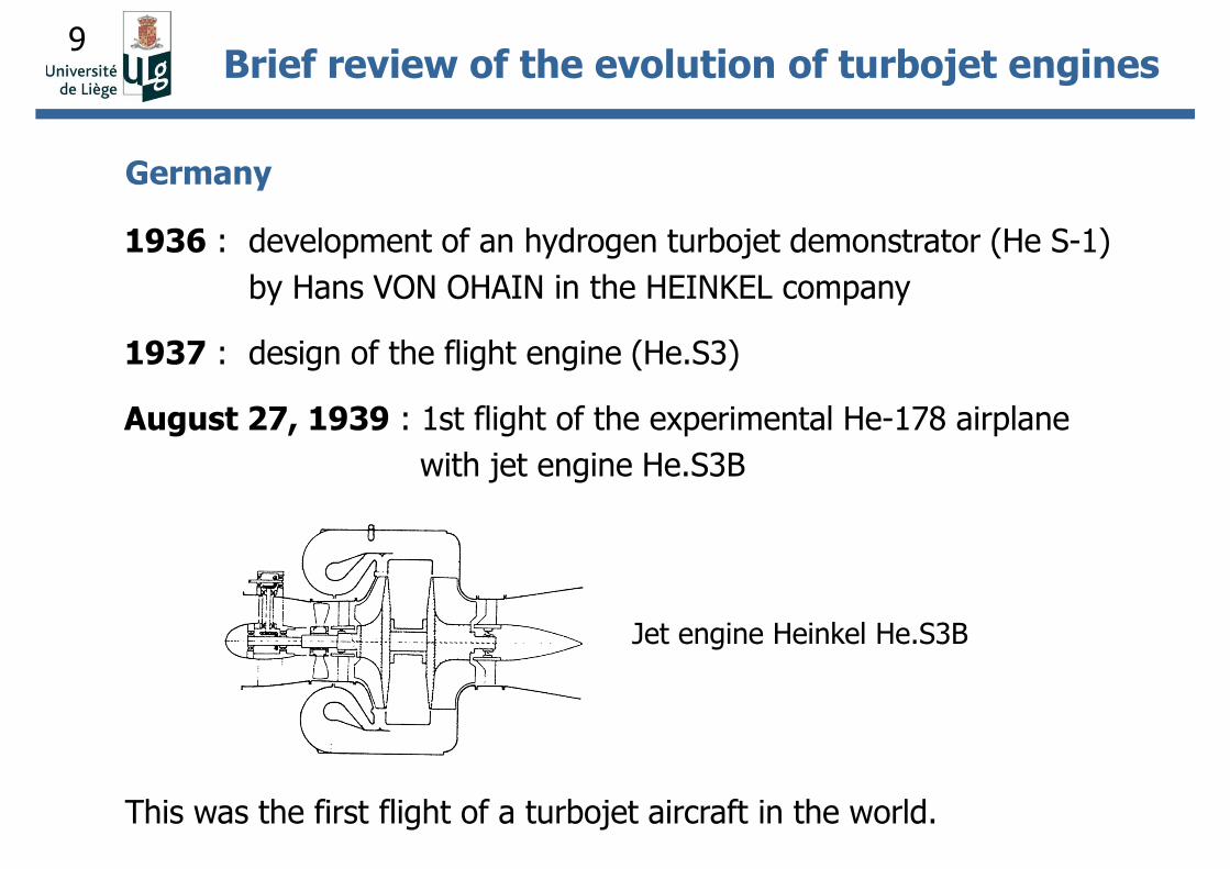
Germany
1936 : development of an hydrogen turbojet demonstrator (He S-1)
by Hans VON OHAIN in the HEINKEL company
1937 : design of the flight engine (He.S3)
August 27, 1939 : 1st flight of the experimental He-178 airplane
with jet engine He.S3B
Jet engine Heinkel He.S3B
This was the first flight of a turbojet aircraft in the world.
Brief review of the evolution of turbojet engines
10
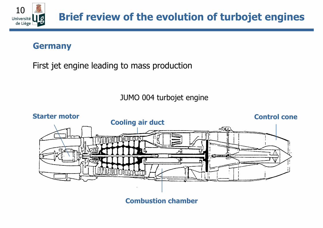
Germany
JUMO 004 turbojet engine
First jet engine leading to mass production
Control cone
Combustion chamber
Starter motorCooling air duct
Brief review of the evolution of turbojet engines
11
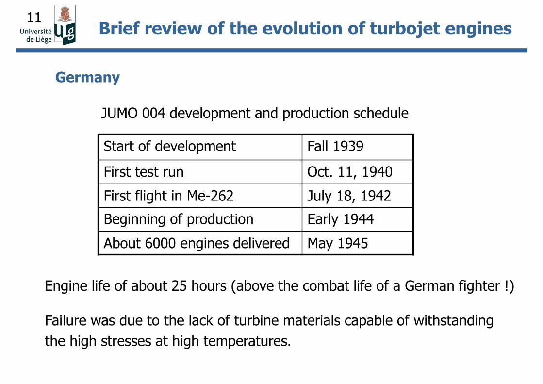
Failure was due to the lack of turbine materials capable of withstanding
the high stresses at high temperatures.
Engine life of about 25 hours (above the combat life of a German fighter !)
Start of development Fall 1939
First test run Oct. 11, 1940
First flight in Me-262 July 18, 1942
Beginning of production Early 1944
About 6000 engines delivered May 1945
JUMO 004 development and production schedule
Germany
Brief review of the evolution of turbojet engines
12
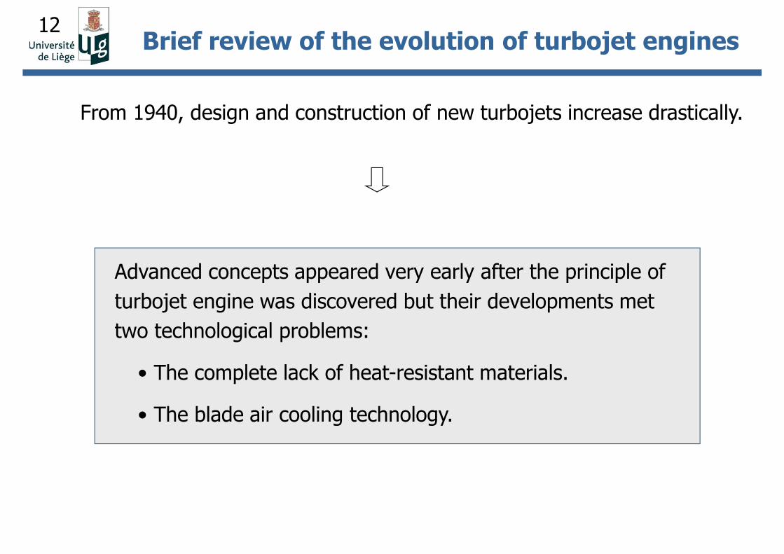
From 1940, design and construction of new turbojets increase drastically.
Advanced concepts appeared very early after the principle of
turbojet engine was discovered but their developments met
two technological problems:
• The complete lack of heat-resistant materials.
• The blade air cooling technology.
Brief review of the evolution of turbojet engines
13
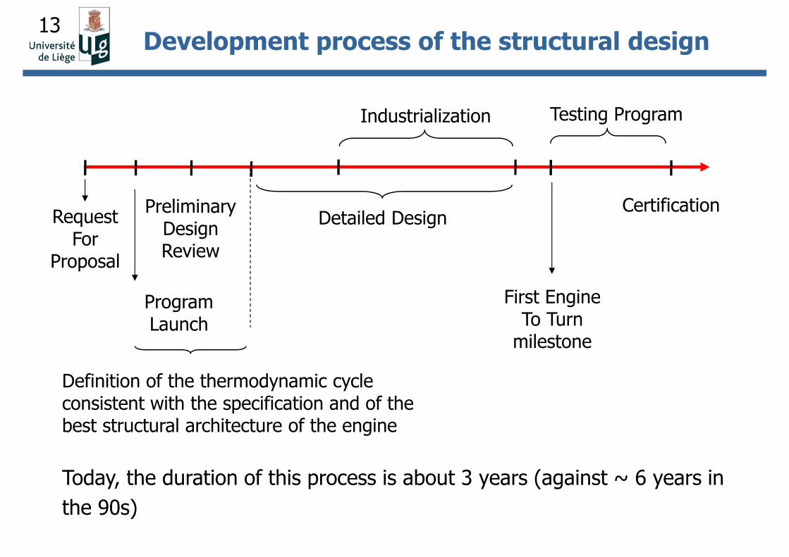
CertificationRequest
For Proposal
Program Launch
Preliminary Design Review
Definition of the thermodynamic cycle consistent with the specification and of the best structural architecture of the engine
Detailed Design
Industrialization
First Engine To Turn
milestone
Testing Program
Today, the duration of this process is about 3 years (against ~ 6 years in
the 90s)
Development process of the structural design
14
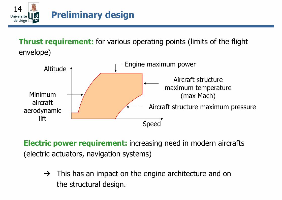
Thrust requirement: for various operating points (limits of the flight
envelope)
Altitude
Speed
Engine maximum power
Aircraft structure maximum temperature
(max Mach)
Aircraft structure maximum pressure
Minimum aircraft
aerodynamic lift
Electric power requirement: increasing need in modern aircrafts
(electric actuators, navigation systems)
This has an impact on the engine architecture and on
the structural design.
Preliminary design
15
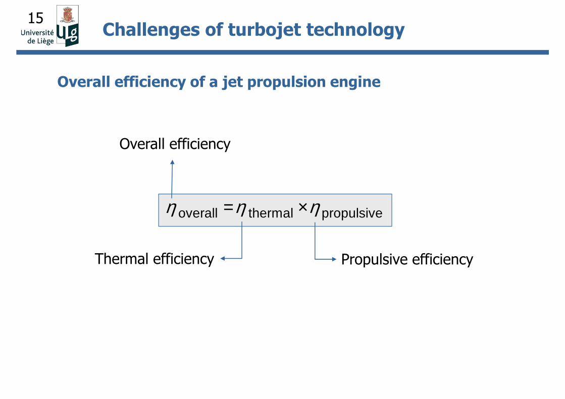
Overall efficiency of a jet propulsion engine
overall thermal propulsiveη η η= ×
Thermal efficiency Propulsive efficiency
Overall efficiency
Challenges of turbojet technology
16
0 1 2 3 4 e
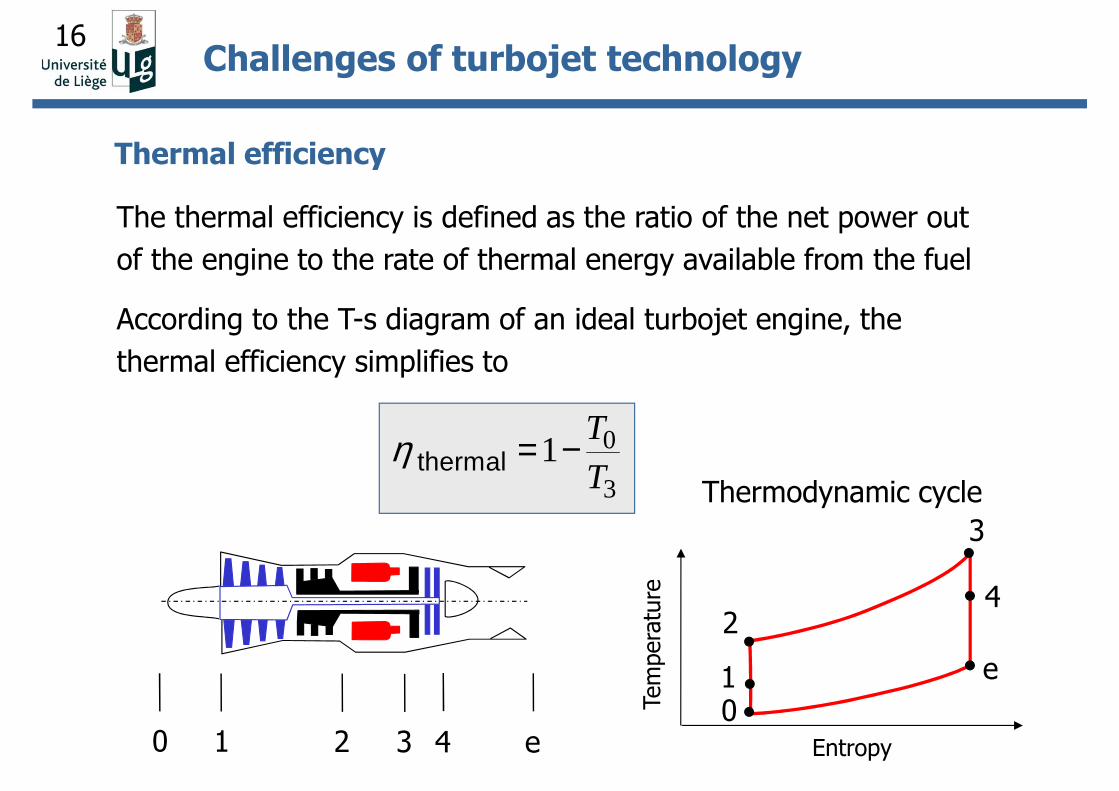
Thermal efficiency
3
1
24
e
0Tem
pera
ture
Entropy
Thermodynamic cycle
0
31thermal
T
Tη = −
The thermal efficiency is defined as the ratio of the net power out
of the engine to the rate of thermal energy available from the fuel
According to the T-s diagram of an ideal turbojet engine, the
thermal efficiency simplifies to
Challenges of turbojet technology
17
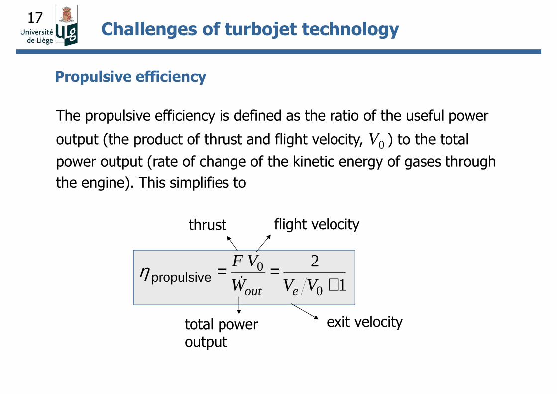
thrust flight velocity
total power output
exit velocity
Propulsive efficiency
The propulsive efficiency is defined as the ratio of the useful power
output (the product of thrust and flight velocity, V0 ) to the total
power output (rate of change of the kinetic energy of gases through
the engine). This simplifies to
0
0
21propulsive
out e
F V
W V Vη = =
+&
Challenges of turbojet technology
18
Ve / V0
η pr
opul
sive
100
1 42 3
9080
70
605040
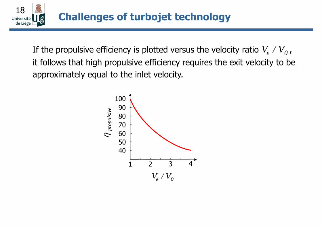
If the propulsive efficiency is plotted versus the velocity ratio Ve / V0 ,
it follows that high propulsive efficiency requires the exit velocity to be
approximately equal to the inlet velocity.
Challenges of turbojet technology
19
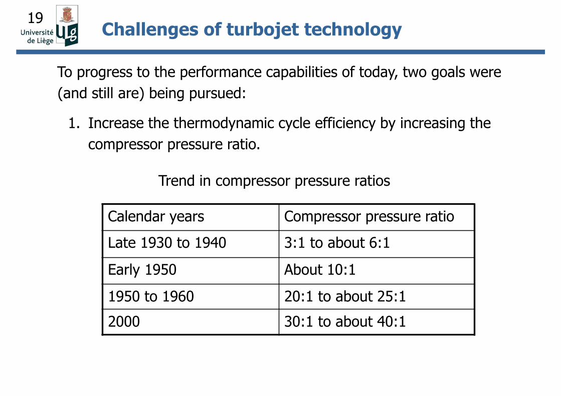
To progress to the performance capabilities of today, two goals were
(and still are) being pursued:
1. Increase the thermodynamic cycle efficiency by increasing the
compressor pressure ratio.
Challenges of turbojet technology
Trend in compressor pressure ratios
Calendar years Compressor pressure ratio
Late 1930 to 1940 3:1 to about 6:1
Early 1950 About 10:1
1950 to 1960 20:1 to about 25:1
2000 30:1 to about 40:1
20
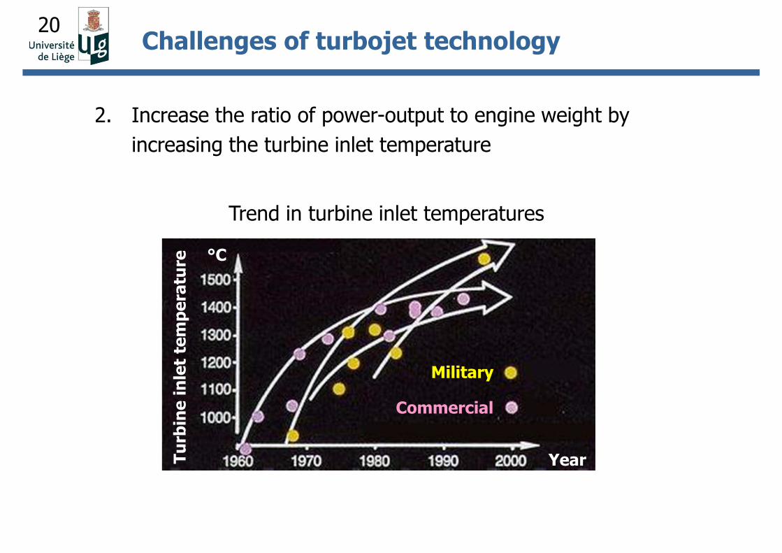
2. Increase the ratio of power-output to engine weight by
increasing the turbine inlet temperature
Challenges of turbojet technology
Trend in turbine inlet temperatures
Tu
rbin
e i
nle
t te
mp
era
ture
Military
Commercial
Year
°C
21
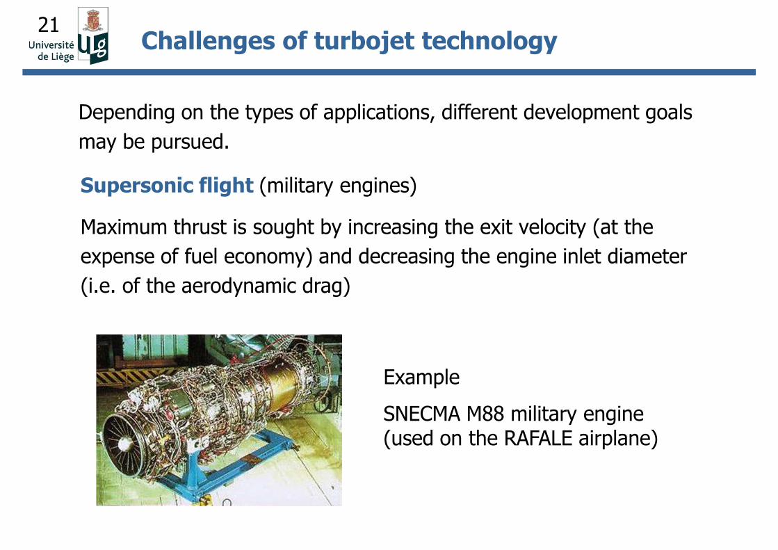
Depending on the types of applications, different development goals
may be pursued.
Supersonic flight (military engines)
Maximum thrust is sought by increasing the exit velocity (at the
expense of fuel economy) and decreasing the engine inlet diameter
(i.e. of the aerodynamic drag)
Challenges of turbojet technology
Example
SNECMA M88 military engine (used on the RAFALE airplane)
22
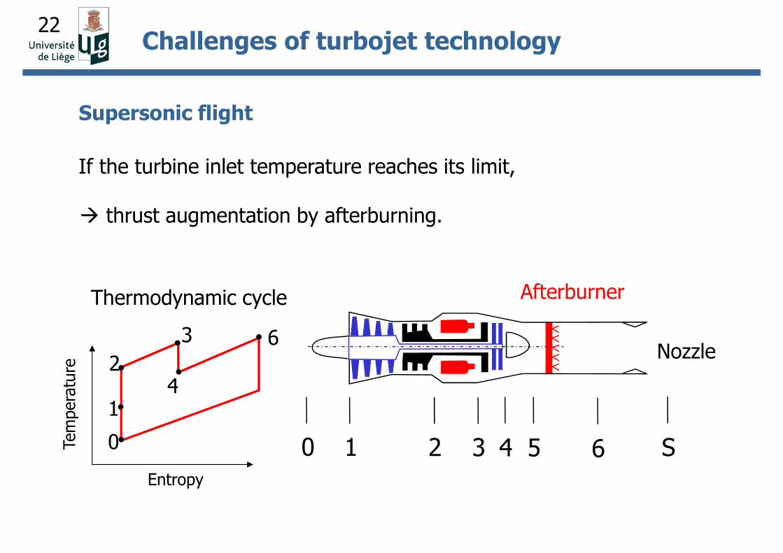
If the turbine inlet temperature reaches its limit,
thrust augmentation by afterburning.
0 1 2 3 4 5
Nozzle
Afterburner
6 S
3
1
24
0
6
Tem
pera
ture
Entropy
Thermodynamic cycle
Challenges of turbojet technology
Supersonic flight
23
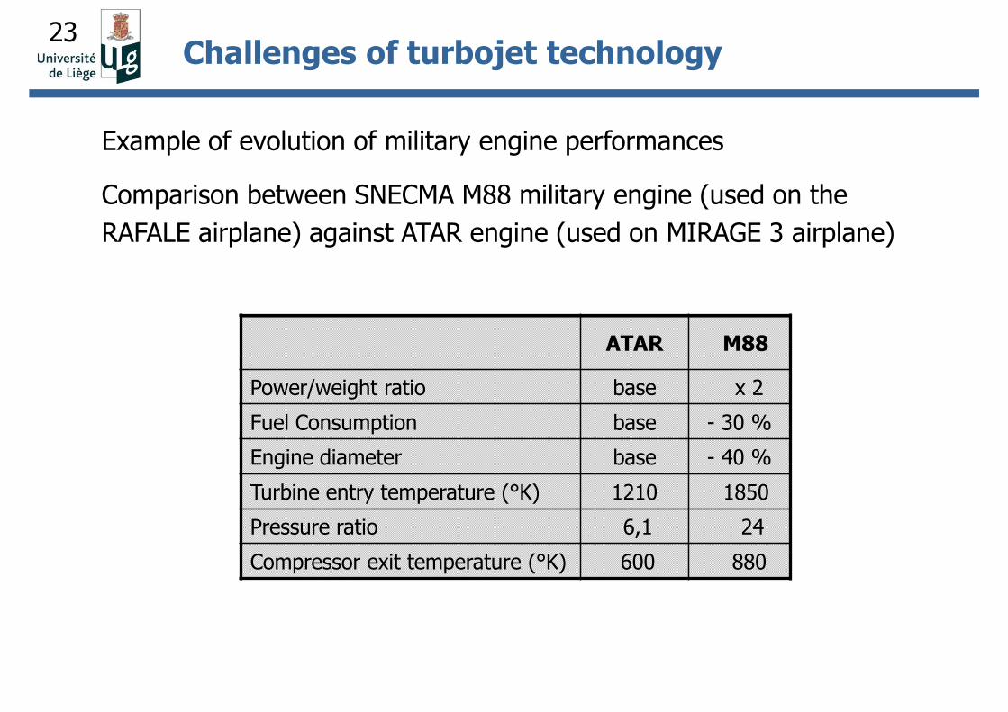
Example of evolution of military engine performances
Comparison between SNECMA M88 military engine (used on the
RAFALE airplane) against ATAR engine (used on MIRAGE 3 airplane)
Challenges of turbojet technology
ATAR M88
Power/weight ratio base x 2
Fuel Consumption base - 30 %
Engine diameter base - 40 %
Turbine entry temperature (°K) 1210 1850
Pressure ratio 6,1 24
Compressor exit temperature (°K) 600 880
24
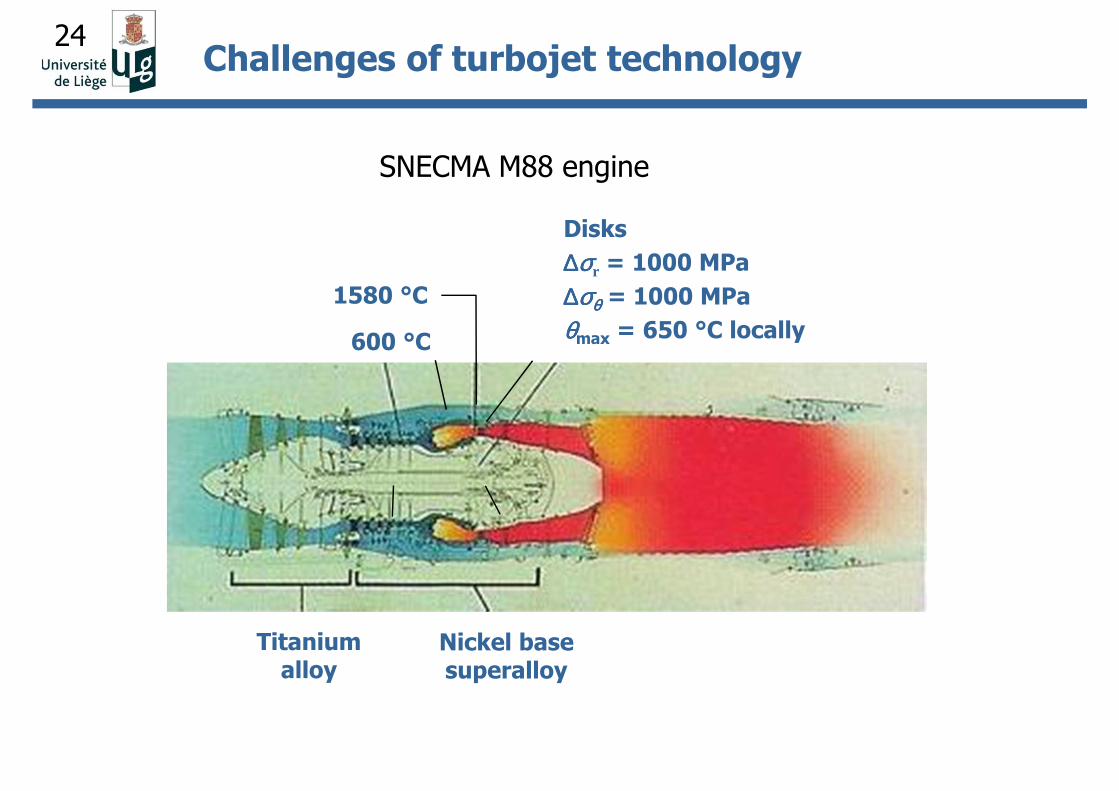
Titanium alloy
Nickel base superalloy
600 °C
1580 °C
Disks
∆∆∆∆σσσσr = 1000 MPa
∆∆∆∆σσσσθθθθ = 1000 MPa
θθθθmax = 650 °C locally
SNECMA M88 engine
Challenges of turbojet technology
25
Subsonic flight (commercial engines)
A low thrust specific fuel consumption is sought by increasing the
propulsive efficiency the principle is to accelerate a larger mass
of air to a lower velocity.
Note: to keep a high thermal efficiency, the pressure ratio and
the turbine inlet temperature must remain high.
Drawback: the frontal area of the engine is quite large
more drag and more weight result
Challenges of turbojet technology
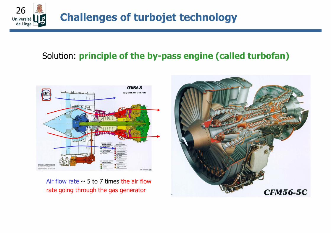
Solution: principle of the by-pass engine (called turbofan)
26
Solution: principle of the by-pass engine (called turbofan)
Air flow rate ~ 5 to 7 times the air flow
rate going through the gas generator
Challenges of turbojet technology
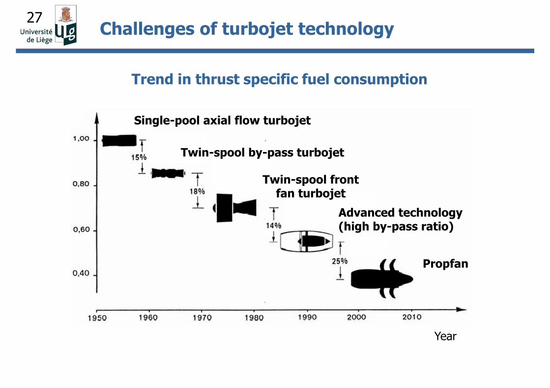
27Challenges of turbojet technology
Trend in thrust specific fuel consumption
Year
Propfan
Single-pool axial flow turbojet
Advanced technology (high by-pass ratio)
Twin-spool front fan turbojet
Twin-spool by-pass turbojet
28
Evolution of turbojet engines to the technology level of today
In conclusion,
• new concepts or technological breakthroughs are rare;
• advancements are rather due evolutionary improvements of the
design
To achieve good performances, parallel research and development
effort were undertaken in areas such as in aerodynamics,
aerothermics, acoustics, combustion process, mechanics, metallurgy,
manufacturing, …
Aim of the course
Study the mechanical aspects of the design.
Challenges of turbojet technology
29
Evolution of turbojet engines - mechanical aspects
1. Increasing of the compressor pressure ratio (r)
In the early turbojets: r ~ 6:1 – 8:1
Increasing r « variable » geometry to adapt the compressor
behavior to various regimes
Mechanical challenges of turbojet technology
30
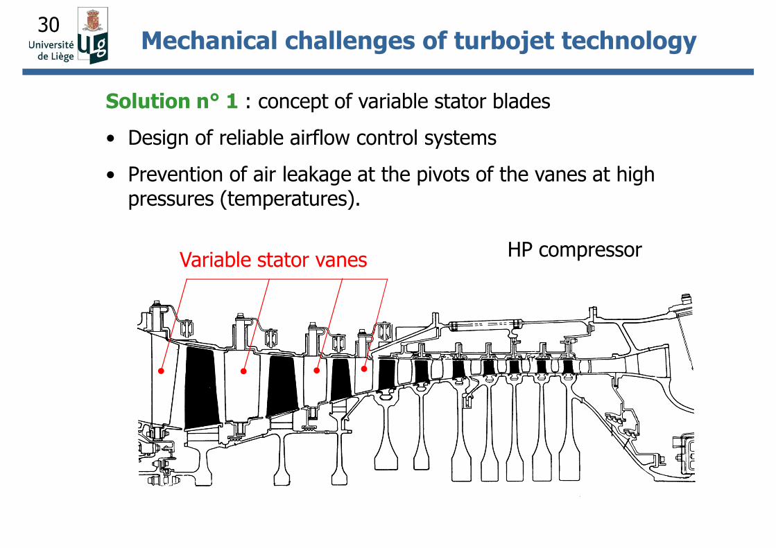
Solution n° 1 : concept of variable stator blades
• Design of reliable airflow control systems
• Prevention of air leakage at the pivots of the vanes at high pressures (temperatures).
Variable stator vanes HP compressor
Mechanical challenges of turbojet technology
31
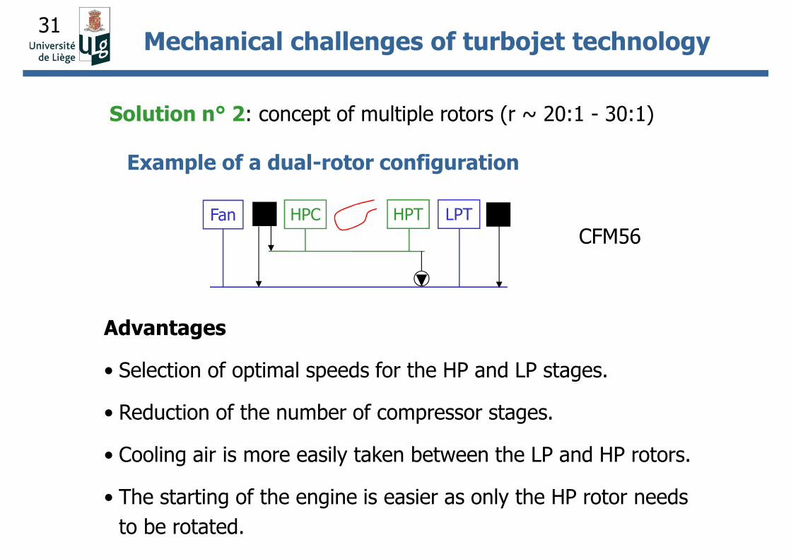
Solution n° 2: concept of multiple rotors (r ~ 20:1 - 30:1)
Example of a dual-rotor configuration
Fan HPC HPT LPT
CFM56
Advantages
• Selection of optimal speeds for the HP and LP stages.
• Reduction of the number of compressor stages.
• Cooling air is more easily taken between the LP and HP rotors.
• The starting of the engine is easier as only the HP rotor needs
to be rotated.
Mechanical challenges of turbojet technology
32
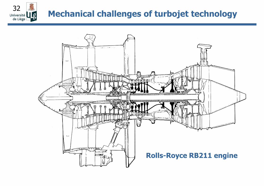
Rolls-Royce RB211 engine
Mechanical challenges of turbojet technology
33
Mechanical challenges
• Analysis of the dynamic behavior of multiple-rotor systems and
prediction of critical speeds.
• Design of disks.
Example
•2 (or even 3) coaxial rotors require to bore the HP disks to allow
passing the LP shaft
the stress level doubles (hole) and increases with the boring
radius
•To place the first critical speeds above the range of operational
speeds, the LP shaft diameter should be as high as possible.
Opposite requirements
Mechanical challenges of turbojet technology
34
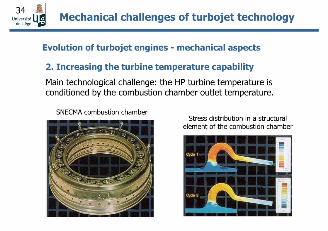
2. Increasing the turbine temperature capability
Main technological challenge: the HP turbine temperature is conditioned by the combustion chamber outlet temperature.
SNECMA combustion chamber
Mechanical challenges of turbojet technology
Evolution of turbojet engines - mechanical aspects
Stress distribution in a structural element of the combustion chamber
35
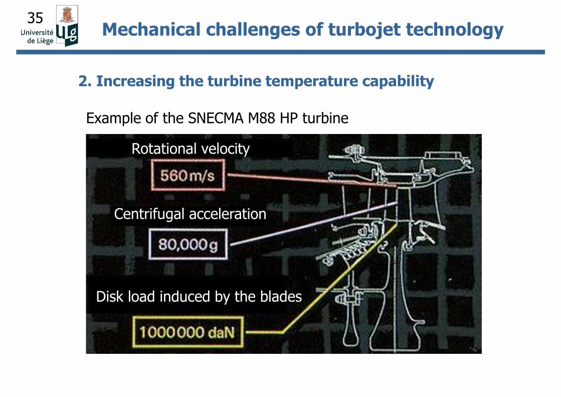
2. Increasing the turbine temperature capability
Mechanical challenges of turbojet technology
Rotational velocity
Centrifugal acceleration
Disk load induced by the blades
Example of the SNECMA M88 HP turbine
36
In early turbojet engines: solid blades the maximum
admissible temperature was directly related to improvement of
structural materials (Tmax ~ 1100 °C)
From 1960-70: development of early air-cooled turbine blades
• hollow blades
• internal cooling of blades (casting using the ‘lost wax’
technique)
Mechanical challenges of turbojet technology
37
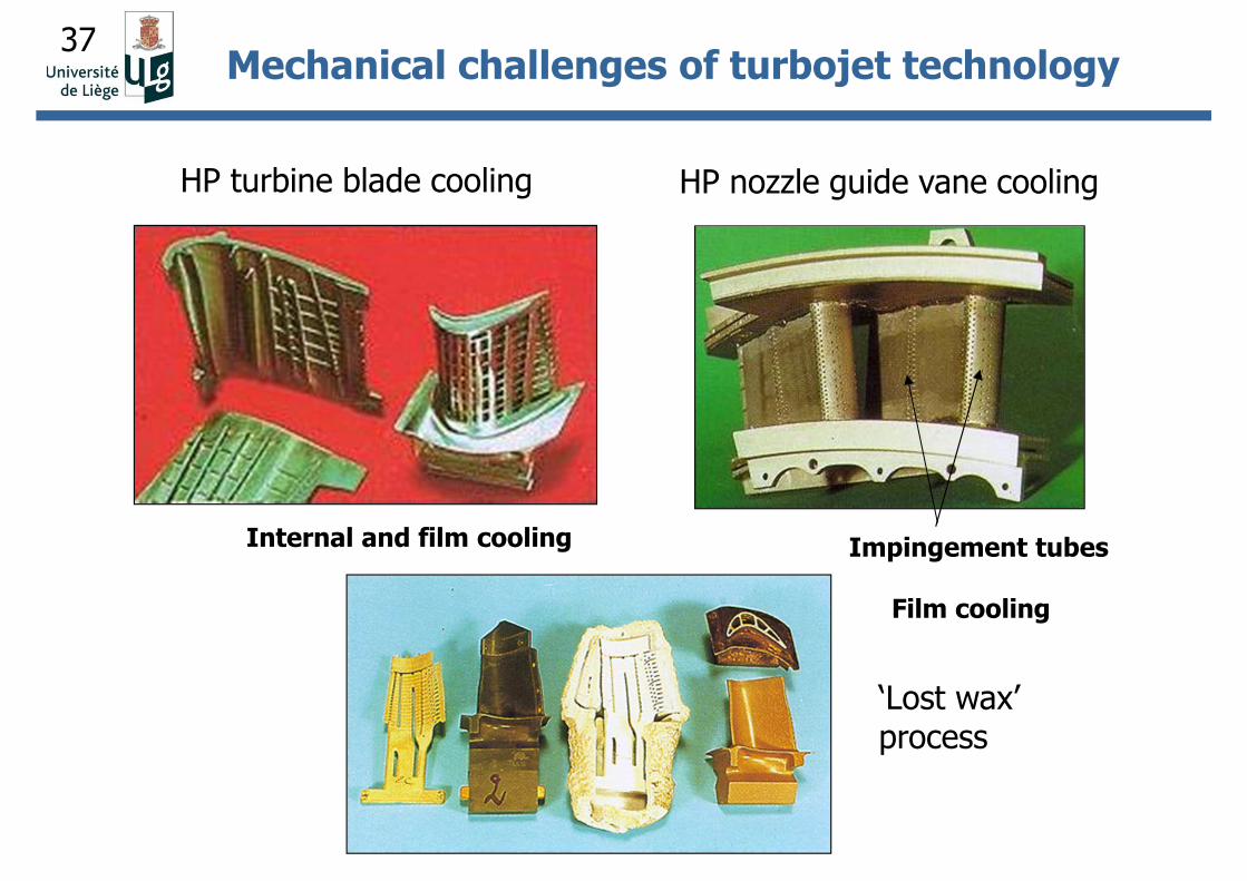
‘Lost wax’ process
Mechanical challenges of turbojet technology
HP nozzle guide vane coolingHP turbine blade cooling
Impingement tubes
Film cooling
Internal and film cooling
38
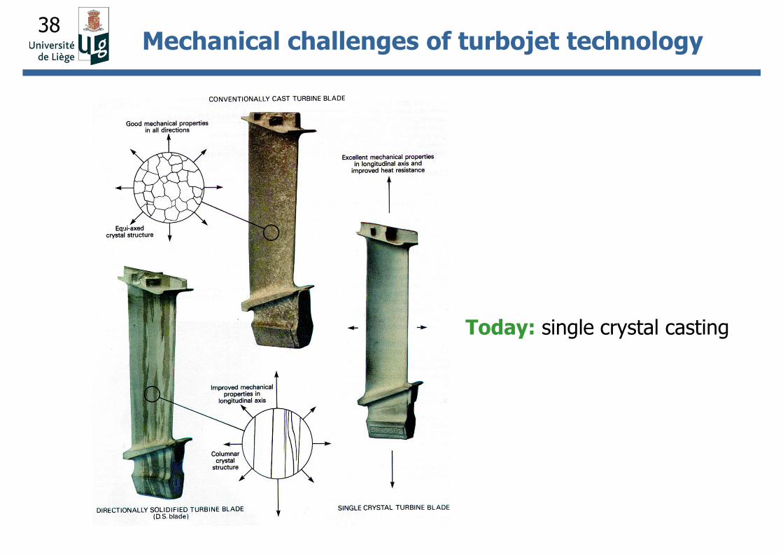
Today: single crystal casting
Mechanical challenges of turbojet technology
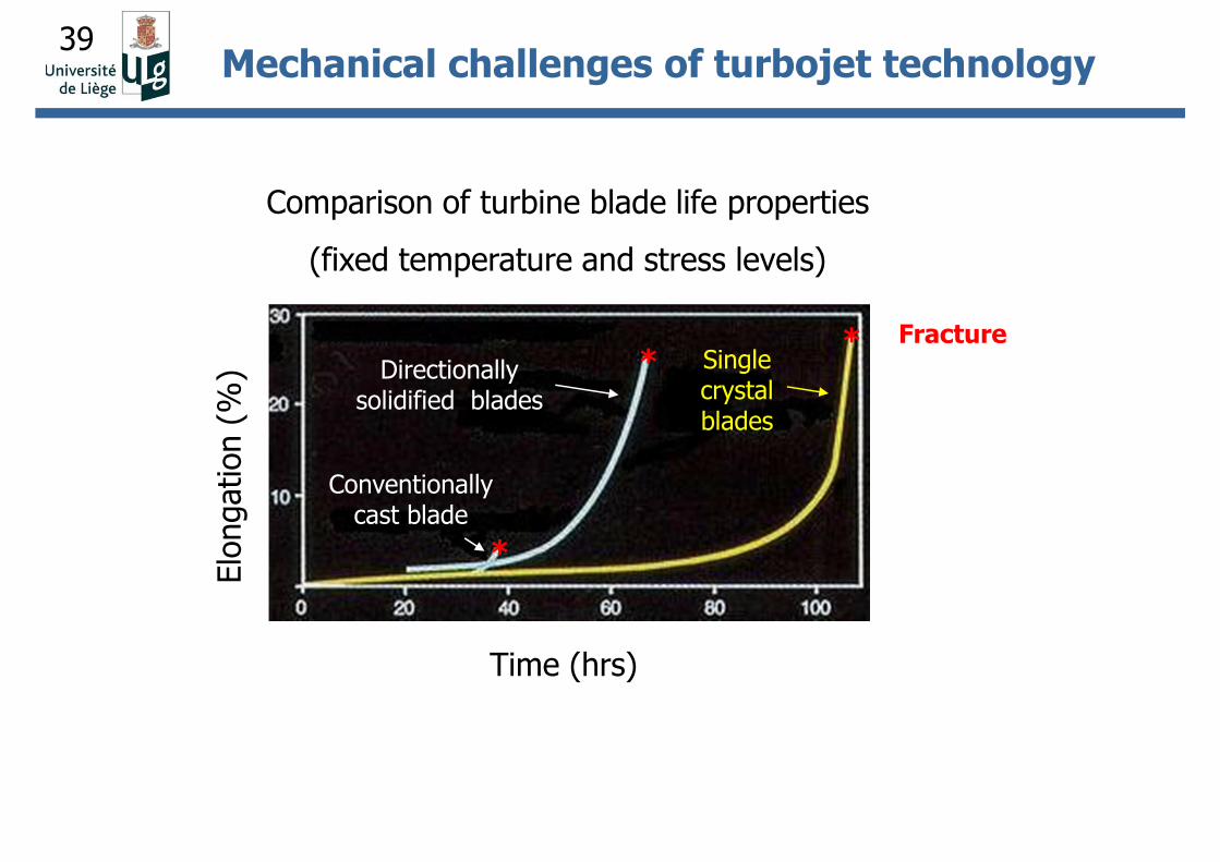
39Mechanical challenges of turbojet technology
Time (hrs)
Single crystal blades
Comparison of turbine blade life properties
(fixed temperature and stress levels)
Single crystal blades
Conventionally cast blade
Directionally solidified blades
Elo
ngation (
%) *
*
*
Fracture
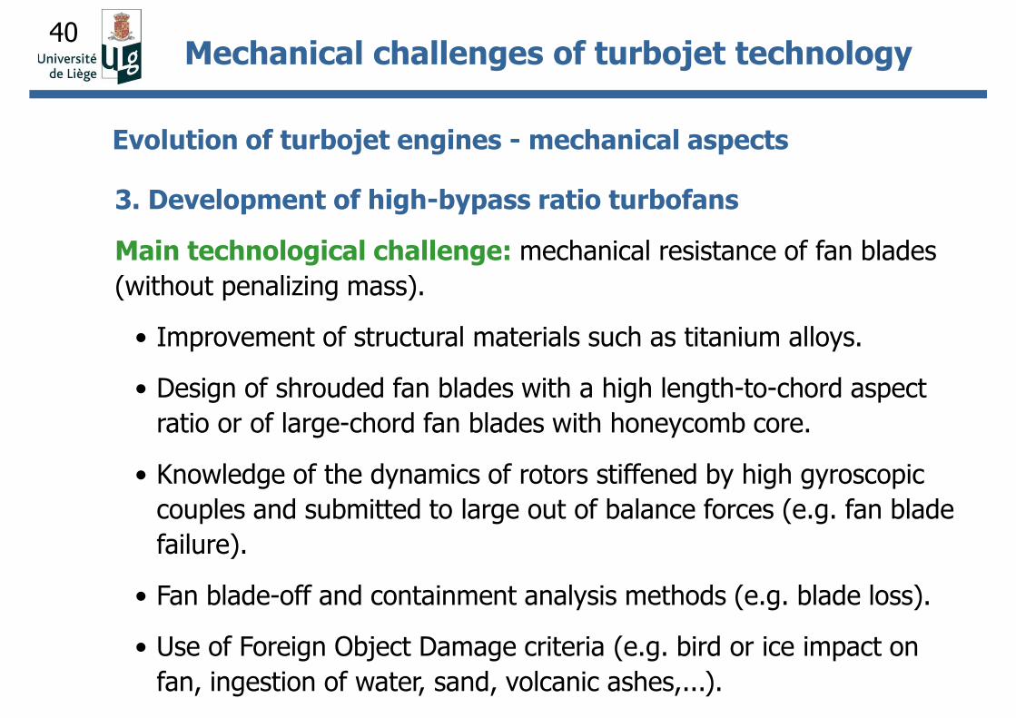
40
3. Development of high-bypass ratio turbofans
Main technological challenge: mechanical resistance of fan blades
(without penalizing mass).
• Improvement of structural materials such as titanium alloys.
• Design of shrouded fan blades with a high length-to-chord aspect
ratio or of large-chord fan blades with honeycomb core.
• Knowledge of the dynamics of rotors stiffened by high gyroscopic
couples and submitted to large out of balance forces (e.g. fan blade
failure).
• Fan blade-off and containment analysis methods (e.g. blade loss).
• Use of Foreign Object Damage criteria (e.g. bird or ice impact on
fan, ingestion of water, sand, volcanic ashes,...).
Mechanical challenges of turbojet technology
Evolution of turbojet engines - mechanical aspects
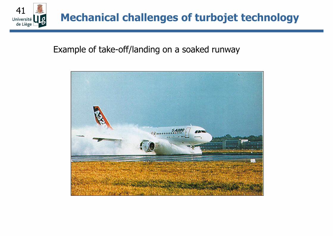
41
Example of take-off/landing on a soaked runway
Mechanical challenges of turbojet technology
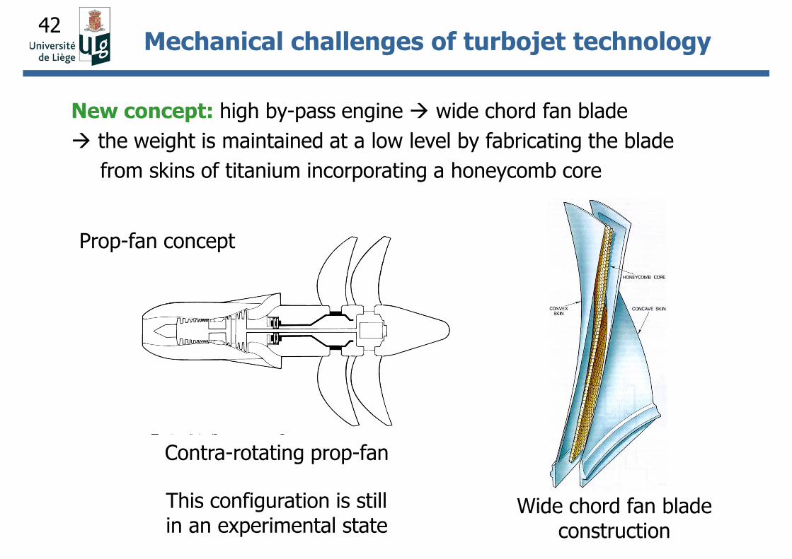
42
New concept: high by-pass engine wide chord fan blade
the weight is maintained at a low level by fabricating the blade
from skins of titanium incorporating a honeycomb core
Prop-fan concept
Wide chord fan blade construction
This configuration is still in an experimental state
Contra-rotating prop-fan
Mechanical challenges of turbojet technology
43
In practice:
• rotors usually present more than one disk and a significant distributed
mass of the shaft;
• supports are not rigid and present speed-dependent stiffness and
damping (produced by oil-film bearings) (≠ support of infinite mass);
• rotor-stator interactions may happen.
The Finite Element Method is commonly used in industry.
Dynamic analysis of industrial rotors
44
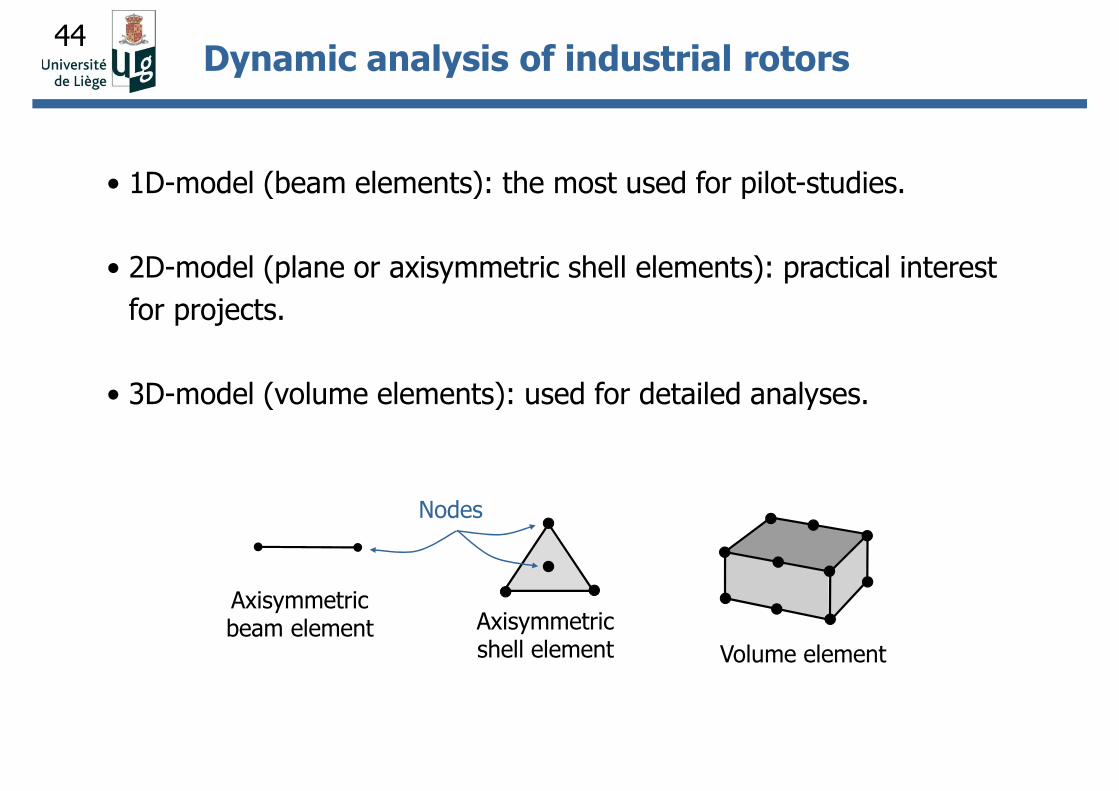
• 1D-model (beam elements): the most used for pilot-studies.
• 2D-model (plane or axisymmetric shell elements): practical interest
for projects.
• 3D-model (volume elements): used for detailed analyses.
Axisymmetric beam element Axisymmetric
shell element Volume element
Nodes
Dynamic analysis of industrial rotors
45
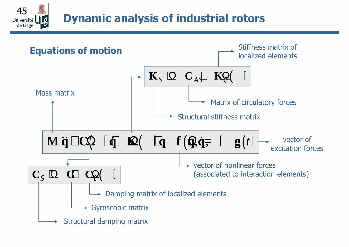
( )S AS+ Ω + ΩK C Kllll
( ) ( ) ( ) ( ), , t+ Ω + Ω + Ω =M q C q K q f q q g&& & &&& & &&& & &&& & &
( )S + Ω + ΩC G Cllll
Structural damping matrix
Gyroscopic matrix
Damping matrix of localized elements
Stiffness matrix of localized elements
Matrix of circulatory forces
Structural stiffness matrix
vector of nonlinear forces (associated to interaction elements)
vector of excitation forces
Mass matrix
Dynamic analysis of industrial rotors
Equations of motion
46
Type of analysis
• Stability analysis and determination of critical speeds
(Campbell diagram).
• Forced response to harmonic excitation.
• Forced response to transient excitation (crossing of critical speeds).
Solution methods for the eigenvalue problem
• Direct methods (substructuring techniques for large scale problems).
• Projection methods (pseudo-modal approach).
Dynamic analysis of industrial rotors
47
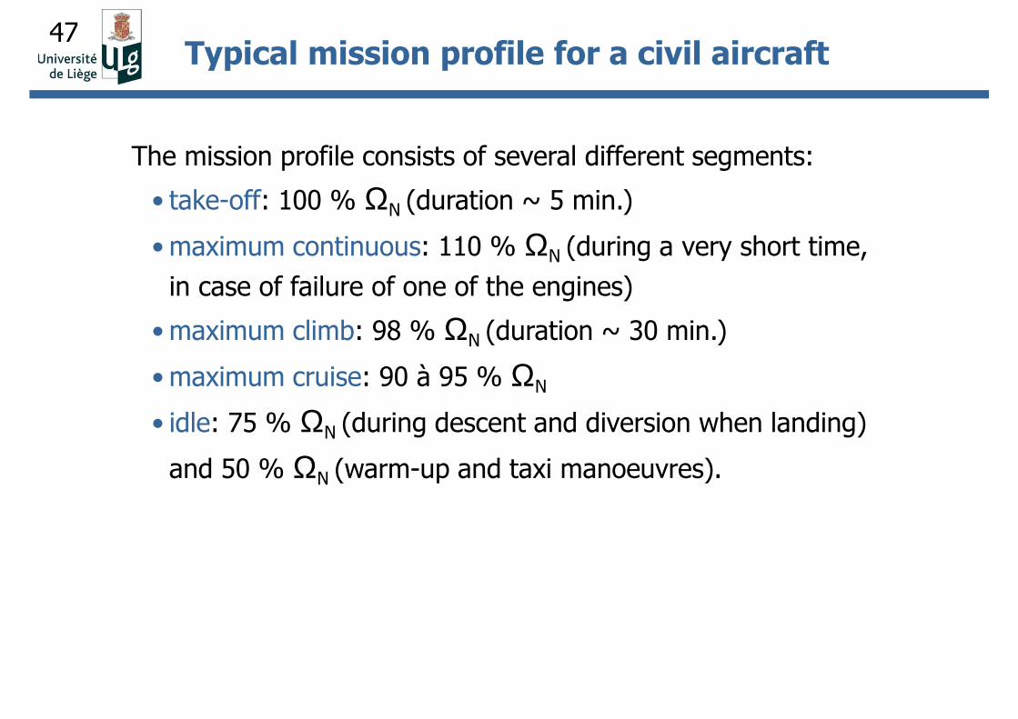
The mission profile consists of several different segments:
• take-off: 100 % ΩN (duration ~ 5 min.)
• maximum continuous: 110 % ΩN (during a very short time,
in case of failure of one of the engines)
• maximum climb: 98 % ΩN (duration ~ 30 min.)
• maximum cruise: 90 à 95 % ΩN
• idle: 75 % ΩN (during descent and diversion when landing)
and 50 % ΩN (warm-up and taxi manoeuvres).
Typical mission profile for a civil aircraft
48
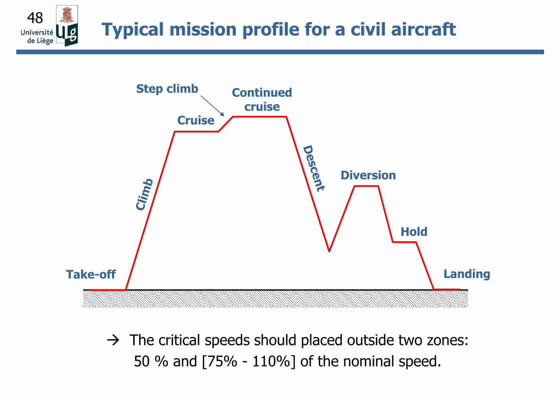
The critical speeds should placed outside two zones:
50 % and [75% - 110%] of the nominal speed.
Typical mission profile for a civil aircraft
Take-off
Cruise
Step climb Continued cruise
Diversion
Hold
Landing
49
Summary of basic steps for the design:
• position the critical speeds outside the range of operational speeds
(e.g. a margin of 10% is usually taken).
• add external damping to lower the resonance amplitude peaks (in
order to keep the rotor-stator gap at the minimum and thus to
optimize engine performances).
• minimize excitation sources (balancing, alignment, optimization of
gaps).
• select low support stiffness (flexible bearing supports) in order to
reduce the dynamic load transmitted through the bearing to the
stator.
Baseline mechanical design of turbojets
50
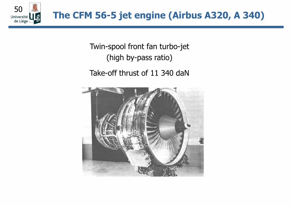
Twin-spool front fan turbo-jet
(high by-pass ratio)
Take-off thrust of 11 340 daN
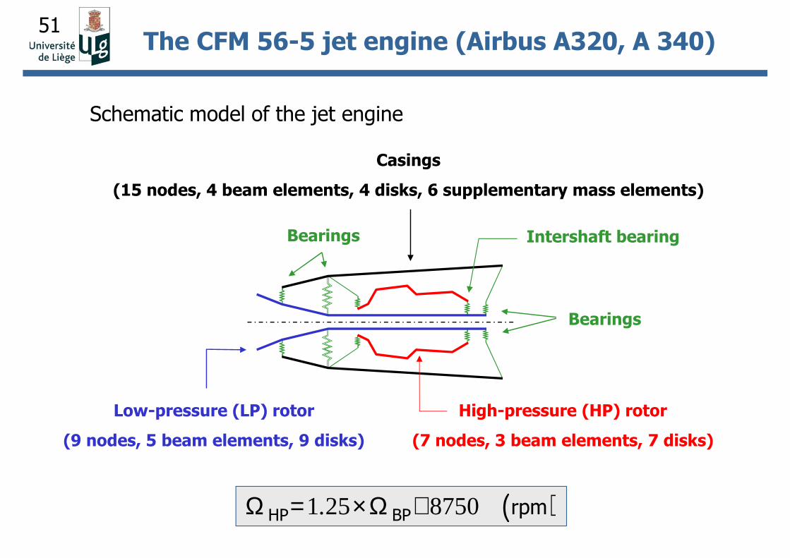
The CFM 56-5 jet engine (Airbus A320, A 340)
51
Low-pressure (LP) rotor
(9 nodes, 5 beam elements, 9 disks)
Casings
(15 nodes, 4 beam elements, 4 disks, 6 supplementary mass elements)
High-pressure (HP) rotor
(7 nodes, 3 beam elements, 7 disks)
( )1 25 8750.Ω = ×Ω +HP BP rpm
The CFM 56-5 jet engine (Airbus A320, A 340)
Schematic model of the jet engine
Bearings
Bearings
Intershaft bearing
52
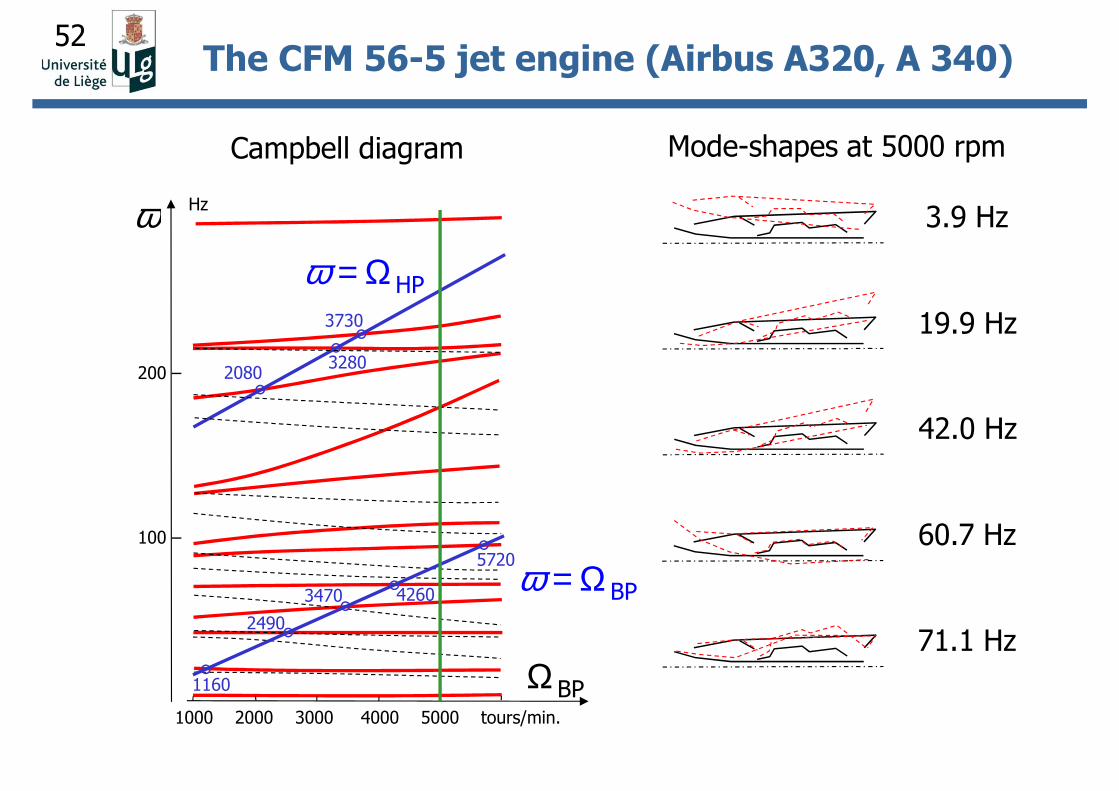
1000 2000 3000 4000 5000 tours/min.
Campbell diagram Mode-shapes at 5000 rpm
200 –
100 –
ω Hz
1160
2490
3470 4260
5720
HPω = Ω
BPω = Ω
BPΩ
3.9 Hz
19.9 Hz
42.0 Hz
60.7 Hz
71.1 Hz
20803280
3730
The CFM 56-5 jet engine (Airbus A320, A 340)
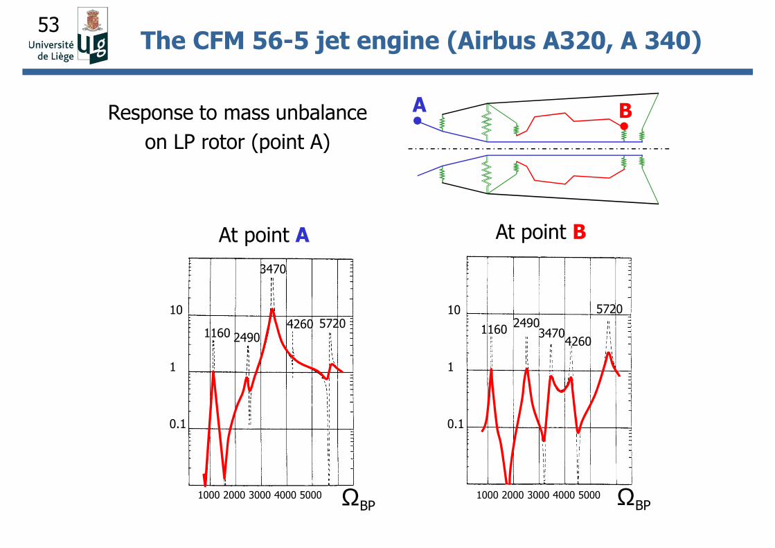
53
Response to mass unbalance
on LP rotor (point A)
A B
10
1
0.1
10
1
0.1
1000 2000 3000 4000 5000 1000 2000 3000 4000 5000
At point A At point B
ΩBP ΩBP
1160 2490
3470
4260 5720 11602490
34704260
5720
The CFM 56-5 jet engine (Airbus A320, A 340)
54
Vibration phenomena are the main cause of failure
of compressor blades and disks.
Requirements
Ability to predict:
• natural frequencies (i.e. to identify critical speeds);
• mode-shapes (i.e. to establish vulnerability to vibrate and
locations of maximum stresses);
• damping levels (i.e. severity of resonance);
• response levels (i.e. fatigue susceptibility);
• stability (i.e. vulnerability to flutter).
Structural dynamics of blades and disks
55
Campbell diagrams
(Natural frequencies vs. Rotation speed)
Standard format for presentation of blade vibration properties in
order to illustrate the essential features and regions of probable
vibration problem areas.
Structural dynamics of blades and disks
56
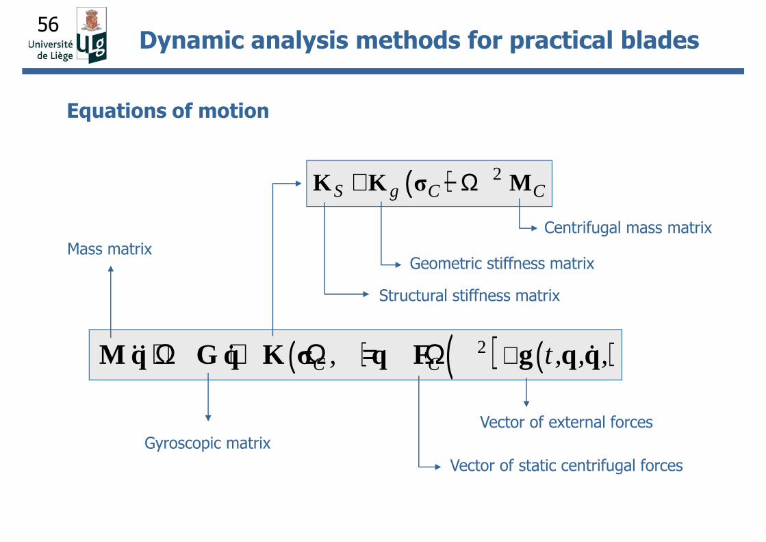
Structural stiffness matrix
( ) 2S g C C+ − ΩK K σ M
( ) ( ) ( )2C C, t , , ,++ Ω + Ω = ΩM q G q K σ q F g q q&& & &&& & &&& & &&& & &
Gyroscopic matrix
Centrifugal mass matrix
Geometric stiffness matrix
Vector of static centrifugal forces
Vector of external forces
Mass matrix
Equations of motion
Dynamic analysis methods for practical blades
57
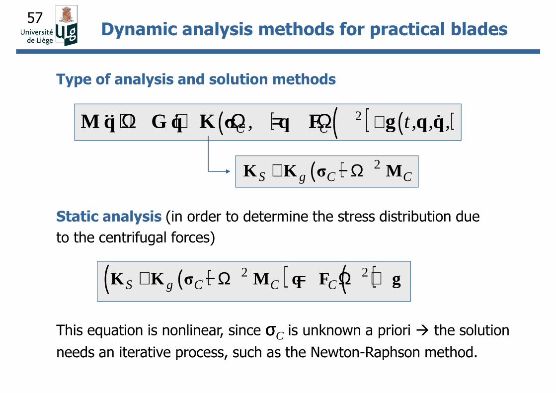
Type of analysis and solution methods
Static analysis (in order to determine the stress distribution due
to the centrifugal forces)
( ) ( ) ( )2C C, t , , ,++ Ω + Ω = ΩM q G q K σ q F g q q&& & &&& & &&& & &&& & &
( ) 2S g C C+ − ΩK K σ M
( )( ) ( )2 2S g C C C+ − Ω = Ω +K K σ M q F g
This equation is nonlinear, since σσσσC is unknown a priori the solution
needs an iterative process, such as the Newton-Raphson method.
Dynamic analysis methods for practical blades
58
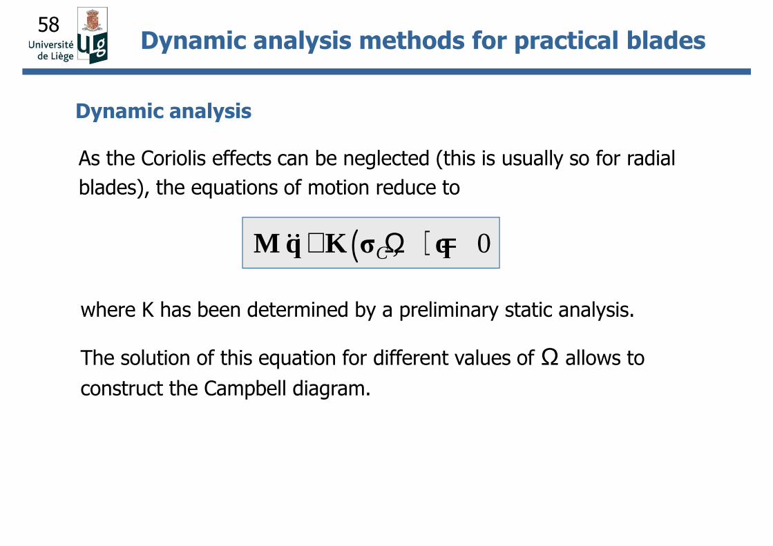
Dynamic analysis
( ) 0C ,+ Ω =M q K σ q&&&&&&&&
As the Coriolis effects can be neglected (this is usually so for radial
blades), the equations of motion reduce to
where K has been determined by a preliminary static analysis.
The solution of this equation for different values of Ω allows to
construct the Campbell diagram.
Dynamic analysis methods for practical blades
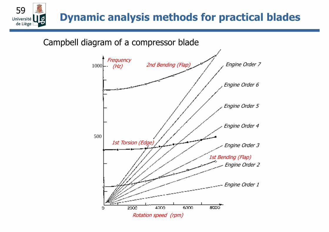
59
Frequency(Hz)
Rotation speed (rpm)
Engine Order 1
Engine Order 2
Engine Order 3
Engine Order 4
Engine Order 5
Engine Order 6
Engine Order 72nd Bending (Flap)
1st Torsion (Edge)
1st Bending (Flap)
Campbell diagram of a compressor blade
1000
500
Dynamic analysis methods for practical blades
60
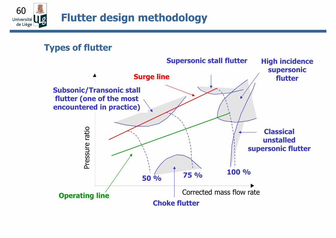
Supersonic stall flutter
Types of flutter
High incidence supersonic
flutter
Subsonic/Transonic stall flutter (one of the most encountered in practice)
Classical unstalled
supersonic flutter
Choke flutter
Surge line
Operating line
Pre
ssure
ratio
Corrected mass flow rate
50 % 75 % 100 %
Flutter design methodology
61
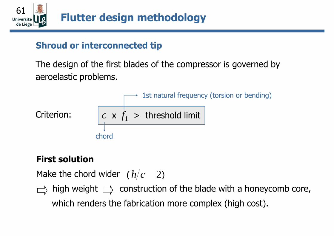
Shroud or interconnected tip
The design of the first blades of the compressor is governed by
aeroelastic problems.
Criterion: c x f1 > threshold limit
chord
1st natural frequency (torsion or bending)
First solution
Make the chord wider
high weight construction of the blade with a honeycomb core,
which renders the fabrication more complex (high cost).
2( )h c
Flutter design methodology
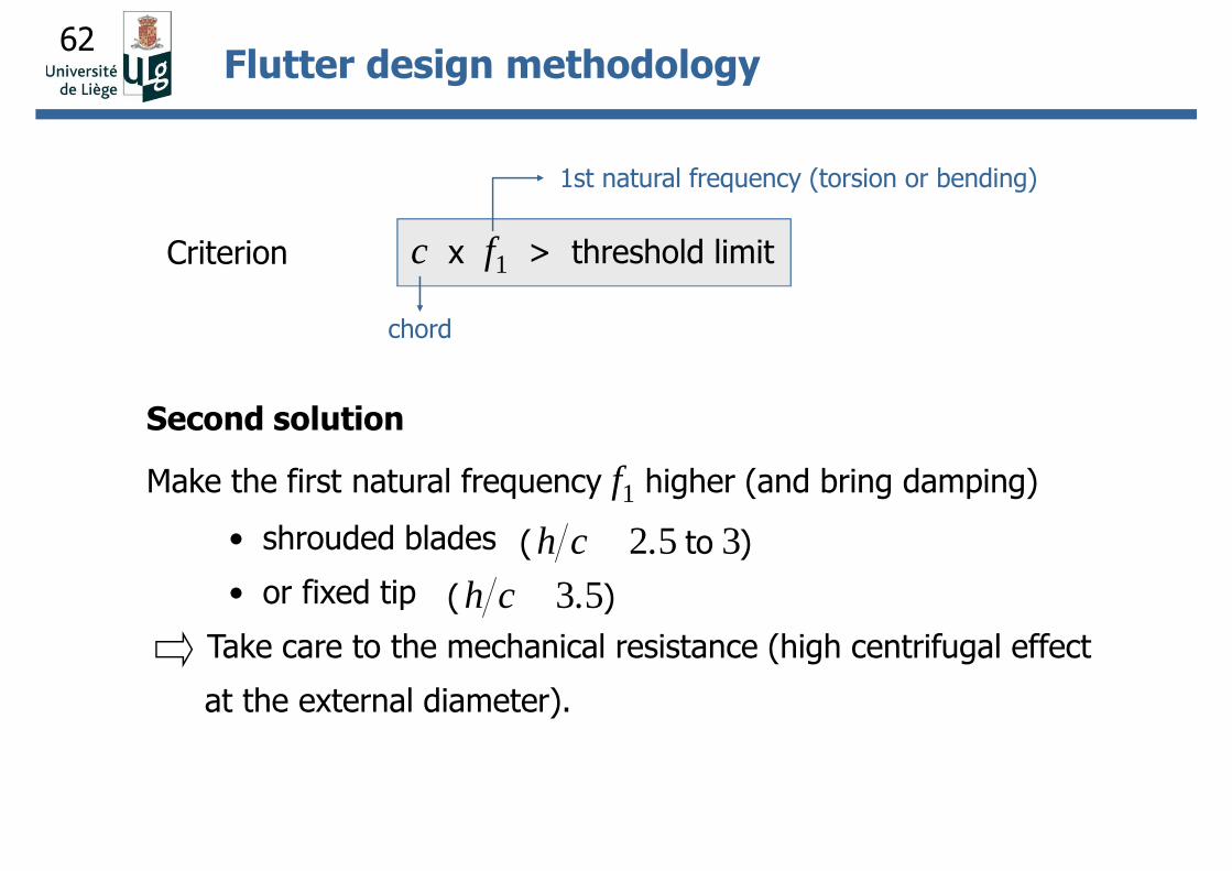
62
Second solution
Make the first natural frequency f1 higher (and bring damping)
• shrouded blades
• or fixed tip
Take care to the mechanical resistance (high centrifugal effect
at the external diameter).
2 5 3h c .( to )
3 5( )h c .
c x f1 > threshold limit
chord
1st natural frequency (torsion or bending)
Criterion
Flutter design methodology
63
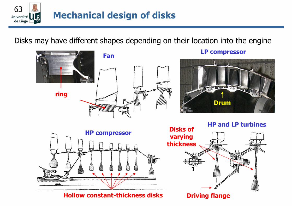
Disks may have different shapes depending on their location into the engine
ring
Drum
HP compressor
Hollow constant-thickness disks
HP and LP turbines
Driving flange
Disks of varying
thickness
FanLP compressor
Mechanical design of disks
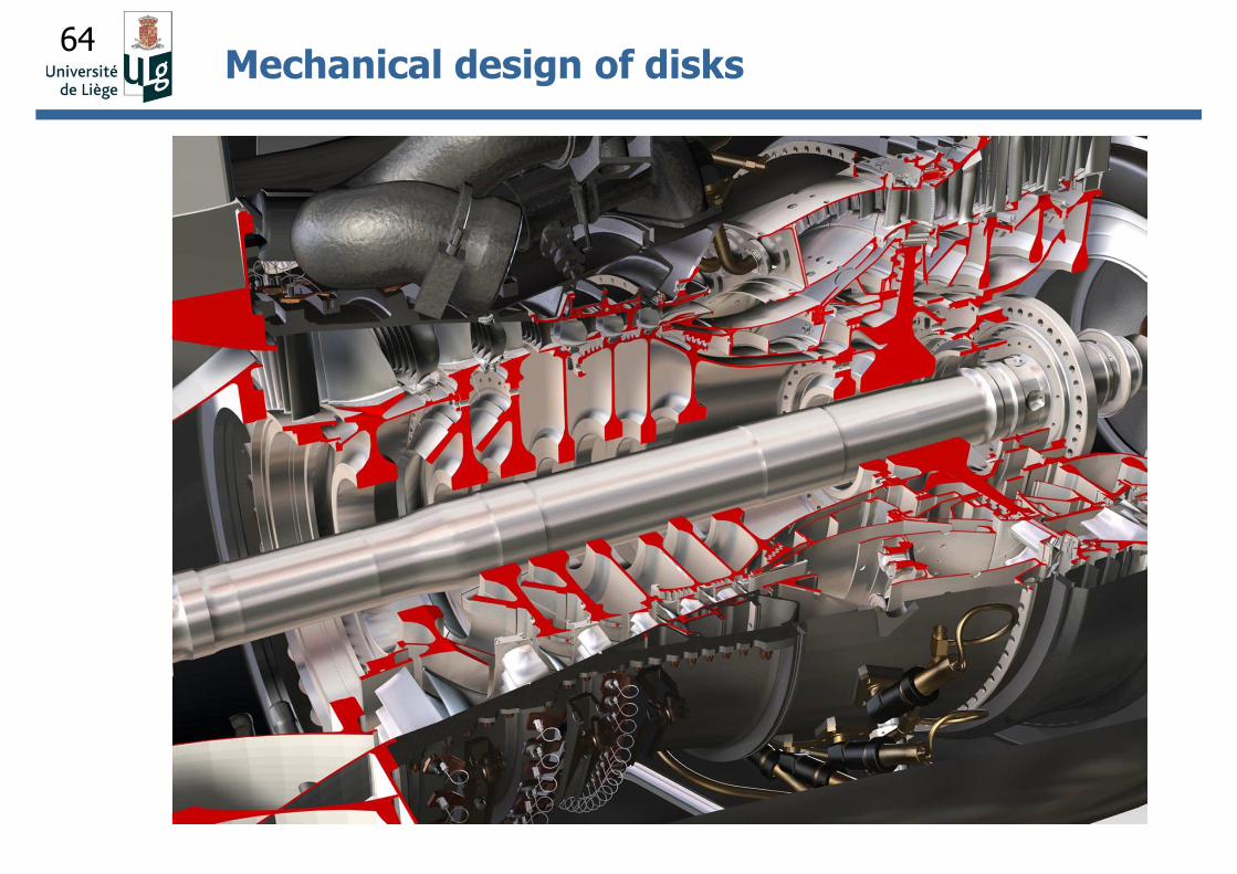
64Mechanical design of disks
65
Sources of stresses in a rotor disk
• Centrifugal body force of disk material;
• Centrifugal load produced by the blades and their attachments to
the disk;
• Thermo-mechanical stresses produced by temperature gradients
between bore and rim;
• Shear stresses produced by torque transmission from turbine to
compressor;
• Bending stresses produced by aerodynamic loads on the blades;
• Dynamical stresses of vibratory origin;
Mechanical design of disks
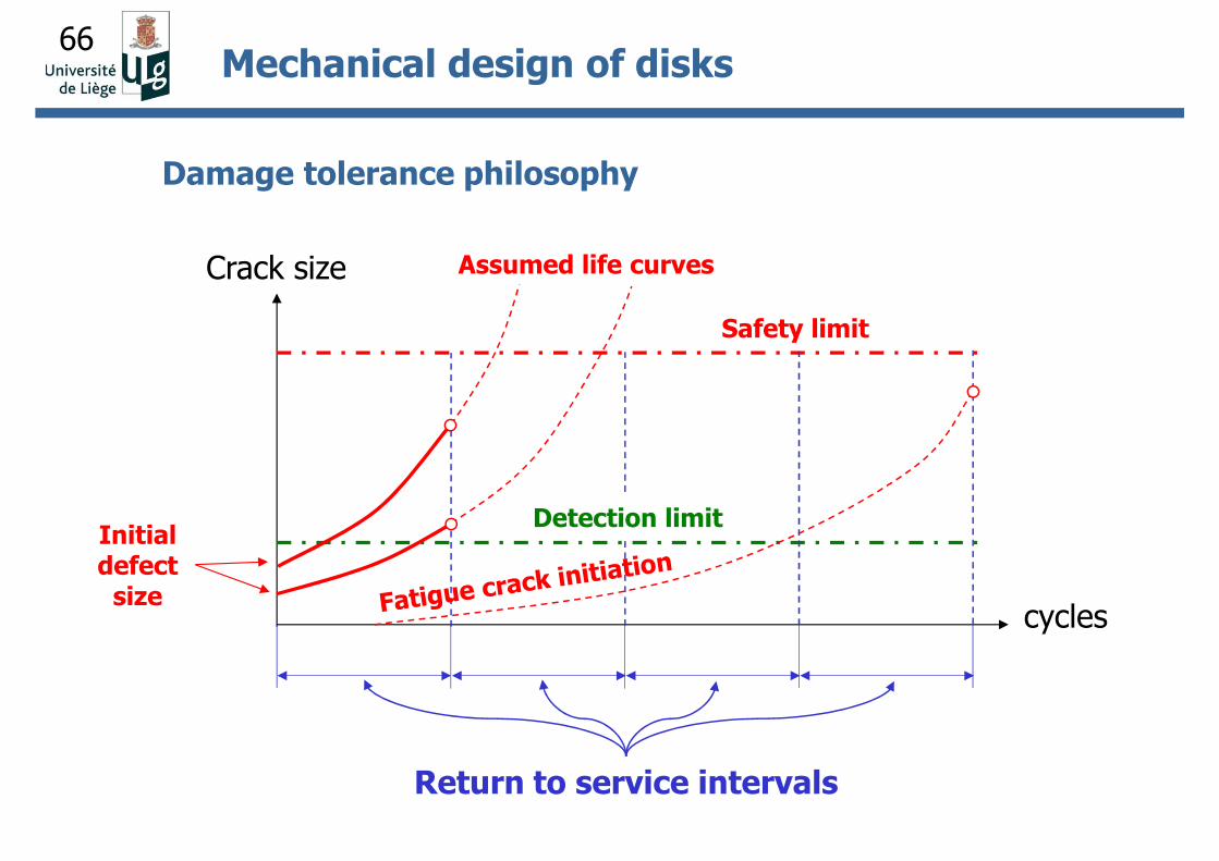
66
Damage tolerance philosophy
Initial defect
size
Return to service intervals
cycles
Crack size
Safety limit
Detection limit
Mechanical design of disks
Assumed life curves
67
An « optimal » mechanical design requires:
1. The precise determination of physical parameters
(temperature, stress and strain distributions) use of refined
finite element models, thermo-elasto-viscoplastic analyses.
2. The perfect understanding of the material properties and the
conditions which lead to failure this corresponds to the use
of an equivalent safety factor of 1.5 or less.
Mechanical design of turbine blades
68
In summary, the mechanical design of turbojets is challenging.
One of the first challenge is the study of the dynamics of multiple rotor
systems submitted to large gyroscopic couples.
Then, depending on the engine component (blade, disk) and on its
location within the engine, problems are of very different nature:
• In the « cold » parts of the engine (fan, LP compressor, HP
compressor), the mechanical design is based on the solution of
dynamical problems (blade vibrations, aeroelastic flutter, bird
impact).
• In the « hot » parts of the engine (HP compressor, combustion
chamber, HP turbine), the design is based on creep and fatigue
calculations and a damage tolerance philosophy is applied.
Conclusion


![International Federation - International Federation of Red ...FR] Principles and Rules RCRC...Created Date: 10/17/2013 12:20:05 PM](https://img.pdfslide.fr/doc/110x75/60e0cf8fab857d36ad1dc718/international-federation-international-federation-of-red-fr-principles-and.jpg)