Embed Size (px)
Citation preview
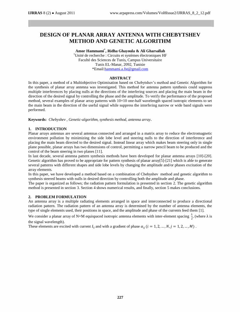
IJRRAS 8 (2) ● August 2011 www.arpapress.com/Volumes/Vol8Issue2/IJRRAS_8_2_12.pdf
227
DESIGN OF PLANAR ARRAY ANTENNA WITH CHEBYTSHEV
METHOD AND GENETIC ALGORITHM
Amor Hammami*, Ridha Ghayoula & Ali Gharsallah
1Unité de recherche : Circuits et systèmes électroniques HF
Faculté des Sciences de Tunis, Campus Universitaire
Tunis EL-Manar, 2092, Tunisie *Email:[email protected]
ABSTRACT
In this paper, a method of a Multiobjective Optimisation based on Chebytshev’s method and Genetic Algorithm for
the synthesis of planar array antenna was investigated. This method for antenna pattern synthesis could suppress
multiple interferences by placing nulls at the directions of the interfering sources and placing the main beam in the
direction of the desired signal by controlling the phase and the amplitude. To verify the performance of the proposed
method, several examples of planar array patterns with 10×10 one-half wavelength spaced isotropic elements to set
the main beam in the direction of the useful signal while suppress the interfering narrow or wide band signals were
performed.
Keywords: Chebyshev , Genetic-algorithm, synthesis method, antenna array.
1. INTRODUCTION
Planar arrays antennas are several antennas connected and arranged in a matrix array to reduce the electromagnetic
environment pollution by minimizing the side lobe level and steering nulls to the direction of interference and
placing the main beam directed to the desired signal. Instead linear array which makes beam steering only in single
plane possible, planar arrays has two dimensions of control, permitting a narrow pencil beam to be produced and the control of the beam steering in two planes [11].
In last decade, several antenna pattern synthesis methods have been developed for planar antenna arrays [10]-[20].
Genetic algorithm has proved to be appropriate for pattern synthesis of planar array[5]-[21] which is able to generate
several patterns with different shapes and side lobe levels by changing the amplitude and/or phases excitation of the
array elements.
In this paper, we have developed a method based on a combination of Chebyshev method and genetic algorithm to
synthesis steered beams with nulls in desired direction by controlling both the amplitude and phase.
The paper is organized as follows; the radiation pattern formulation is presented in section 2. The genetic algorithm
method is presented in section 3. Section 4 shows numerical results, and finally, section 5 makes conclusions.
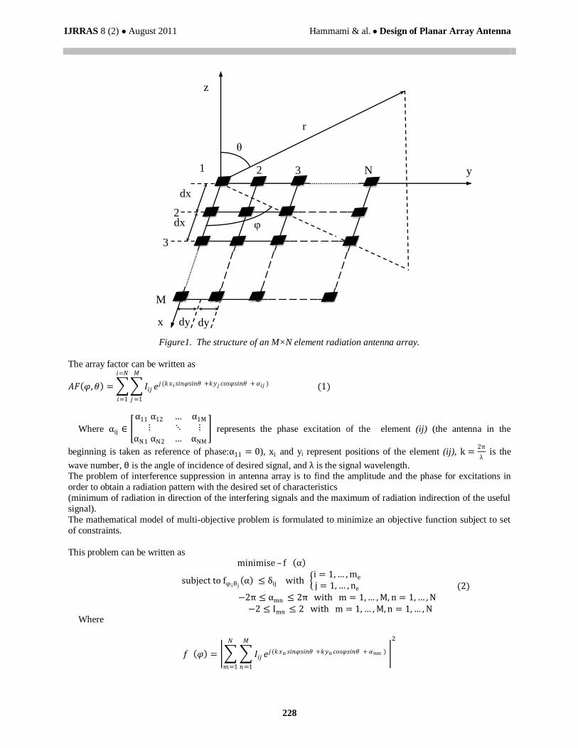
2. PROBLEM FORMULATION An antenna array is a multiple radiating elements arranged in space and interconnected to produce a directional
radiation pattern. The radiation pattern of an antenna array is determined by the number of antenna elements, the
type of single elements used, their positions in space, and the amplitude and phase of the currents feed them [1].
We consider a planar array of N×M equispaced isotropic antenna elements with inter-element spacing λ
2, (where λ is
the signal wavelength).
These elements are excited with current Iij and with a gradient of phase 𝛼𝑖𝑗 (𝑖 = 1, 2, … , 𝑁, 𝑗 = 1, 2, … ,𝑀) .
IJRRAS 8 (2) ● August 2011 Hammami & al. ● Design of Planar Array Antenna
228
Figure1. The structure of an M×N element radiation antenna array.
The array factor can be written as
𝐴𝐹 𝜑,𝜃 = 𝐼𝑖𝑗 𝑒𝑗(𝑘𝑥𝑖𝑠𝑖𝑛𝜑𝑠𝑖𝑛𝜃 +𝑘𝑦𝑗 𝑐𝑜𝑠𝜑𝑠𝑖𝑛𝜃 + 𝛼𝑖𝑗 )
𝑀
𝑗 =1
𝑖=𝑁
𝑖=1
(1)
Where αij ∈
α11 α12 … α1M
⋮ ⋱ ⋮αN1 αN2 … αNM
represents the phase excitation of the element (ij) (the antenna in the
beginning is taken as reference of phase:α11 = 0), xi and yi represent positions of the element (ij), k =2π
λ is the
wave number, θ is the angle of incidence of desired signal, and λ is the signal wavelength. The problem of interference suppression in antenna array is to find the amplitude and the phase for excitations in
order to obtain a radiation pattern with the desired set of characteristics
(minimum of radiation in direction of the interfering signals and the maximum of radiation indirection of the useful
signal).
The mathematical model of multi-objective problem is formulated to minimize an objective function subject to set
of constraints.
This problem can be written as minimise – f α
subject to fφ iθ j α ≤ δij with
i = 1,… , me
j = 1,… , ne
−2π ≤ αmn ≤ 2π with m = 1,… , M, n = 1, … , N −2 ≤ Imn ≤ 2 with m = 1, … , M, n = 1,… , N
(2)
Where
𝑓 𝜑 = 𝐼𝑖𝑗 𝑒𝑗(𝑘𝑥𝑛 𝑠𝑖𝑛𝜑𝑠𝑖𝑛𝜃 +𝑘𝑦𝑛 𝑐𝑜𝑠𝜑𝑠𝑖𝑛𝜃 + 𝛼𝑛𝑚 )
𝑀
𝑛=1
𝑁
𝑚=1
2
dy dy x
dx
dx
1
2
3
N
M
3 2
z
y
r
θ
φ
IJRRAS 8 (2) ● August 2011 Hammami & al. ● Design of Planar Array Antenna
229
fθ i=
fφ1θ1 fφ1θ12
… fφ1θM
⋮ ⋱ ⋮fφNθ1
fφ2θM… fφNθM
T
is the matrix of objective functions, me is the numbers of the desired signal, (φi,
θj) is the directions of interfering signals, δij is the levels in the regions of the suppressed sectors respectively, and
me and ne are the number of the sampled angular direction along the x-axis and y-axis, respectively.
Inm , with m = 1, 2,… , 𝑀, n = 1, 2, … , N is amplitudes of each array element which is defined by -40 dB
Chebyshev algorithm.
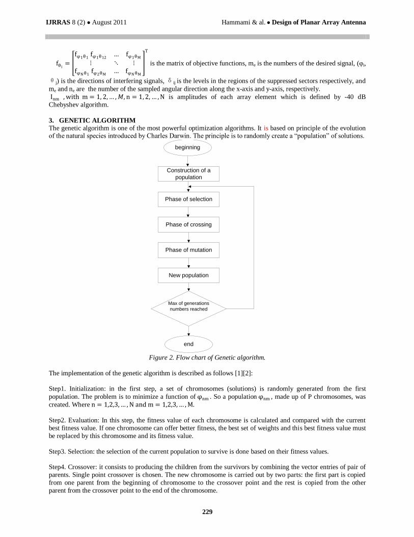
3. GENETIC ALGORITHM
The genetic algorithm is one of the most powerful optimization algorithms. It is based on principle of the evolution of the natural species introduced by Charles Darwin. The principle is to randomly create a “population” of solutions.
Construction of a
population
beginning
Phase of selection
Phase of crossing
Phase of mutation
New population
end
Max of generations
numbers reached
Figure 2. Flow chart of Genetic algorithm.
The implementation of the genetic algorithm is described as follows [1][2]:
Step1. Initialization: in the first step, a set of chromosomes (solutions) is randomly generated from the first
population. The problem is to minimize a function of φnm . So a population φnm , made up of P chromosomes, was
created. Where n = 1,2,3,… , N and m = 1,2,3,… , M.
Step2. Evaluation: In this step, the fitness value of each chromosome is calculated and compared with the current
best fitness value. If one chromosome can offer better fitness, the best set of weights and this best fitness value must
be replaced by this chromosome and its fitness value.
Step3. Selection: the selection of the current population to survive is done based on their fitness values.
Step4. Crossover: it consists to producing the children from the survivors by combining the vector entries of pair of
parents. Single point crossover is chosen. The new chromosome is carried out by two parts: the first part is copied
from one parent from the beginning of chromosome to the crossover point and the rest is copied from the other
parent from the crossover point to the end of the chromosome.
IJRRAS 8 (2) ● August 2011 Hammami & al. ● Design of Planar Array Antenna
230
Step5. Mutation: this operator is introduced to mitigate the disappearance of information (bits) of the population. Its
role consists in modifying by chance, with a certain probability, the value of a bit.
Step6. Stopping criteria: if the number of the current generation is equal to the predefined number of generations,
end the algorithm. Otherwise, steps 2-5 are repeated. The best set of phase shift weights can be generated after termination.
4. NUMERICAL RESULTS
To demonstrate the validity of the proposed method for steering single, multiple and broad nulls with the imposed
directions by controlling the element excitations, several computer simulation examples using a planar array with
one half wave inter-element spaced 10×10 isotropic elements were presented.
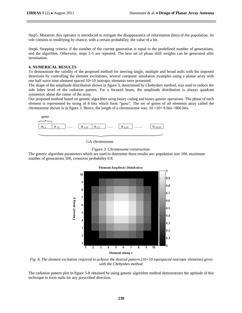
The shape of the amplitude distribution shown in figure 3, determined by Chebyshev method, was used to reduce the
side lobes level of the radiation pattern. For a focused beam, the amplitude distribution is always quadrant
symmetric about the center of the array.
Our proposed method based on genetic algorithm using binary coding and binary genetic operations. The phase of each
element is represented by string of 8 bits which form “gene”. The set of genes of all elements array called the
chromosome shown is in figure 3. Hence, the length of a chromosome was: 10 ×10× 8 bits =800 bits.
α1,1 α 12 …. α 1,10 α 2,1 …. α 2,10 …… α 10,10
Figure 3. Chromosome construction.
The genetic algorithm parameters which are used to determine these results are: population size 100, maximum
number of generations 500, crossover probability 0.8.
Fig. 4. The element excitation required to achieve the desired pattern (10×10 equispaced isotropic elements) given
with the Chebyshev method.
The radiation pattern plot in figure 5-8 obtained by using genetic algorithm method demonstrates the aptitude of this
technique to form nulls for any prescribed direction.
GA chromosome
gene
IJRRAS 8 (2) ● August 2011 Hammami & al. ● Design of Planar Array Antenna
231
-180 -150 -120 -90 -60 -30 0 30 60 90 120 150 180
-80
-70
-60
-50
-40
-30
-20
-10
0
(deg)
Am
pli
tue(d
B)
=20°
=80°
Desiredsignal @5°
interference
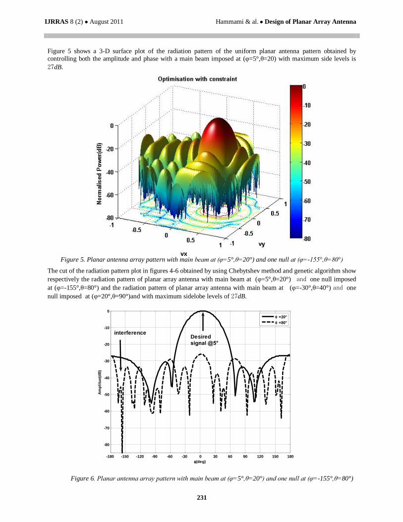
Figure 5 shows a 3-D surface plot of the radiation pattern of the uniform planar antenna pattern obtained by
controlling both the amplitude and phase with a main beam imposed at (φ=5°,θ=20) with maximum side levels is
27dB.
Figure 5. Planar antenna array pattern with main beam at (φ=5°,θ=20°) and one null at (φ=-155°,θ=80°)
The cut of the radiation pattern plot in figures 4-6 obtained by using Chebytshev method and genetic algorithm show
respectively the radiation pattern of planar array antenna with main beam at (φ=5°,θ=20°) and one null imposed
at (φ=-155°,θ=80°) and the radiation pattern of planar array antenna with main beam at (φ=-30°,θ=40°) and one
null imposed at (φ=20°,θ=90°)and with maximum sidelobe levels of 27dB.
Figure 6. Planar antenna array pattern with main beam at (φ=5°,θ=20°) and one null at (φ=-155°,θ=80°)
IJRRAS 8 (2) ● August 2011 Hammami & al. ● Design of Planar Array Antenna
232
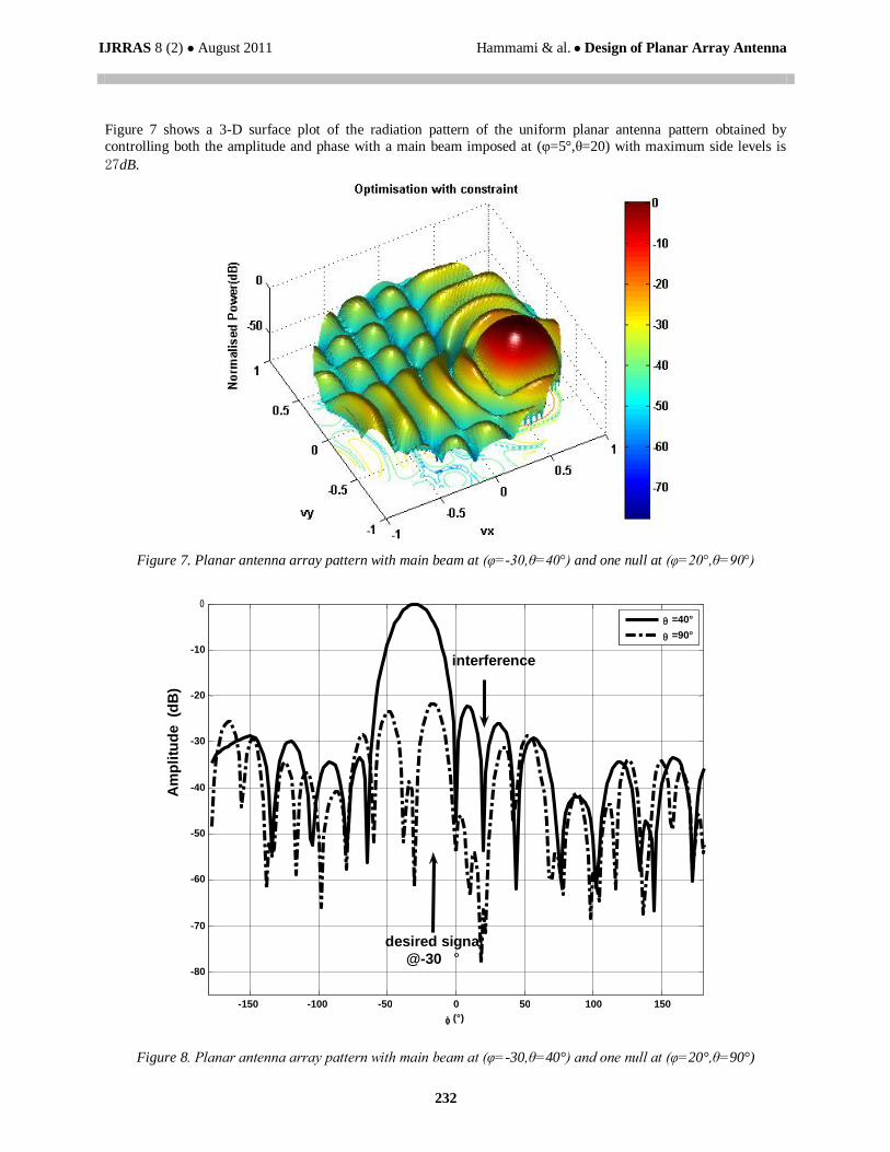
Figure 7 shows a 3-D surface plot of the radiation pattern of the uniform planar antenna pattern obtained by
controlling both the amplitude and phase with a main beam imposed at (φ=5°,θ=20) with maximum side levels is
27dB.
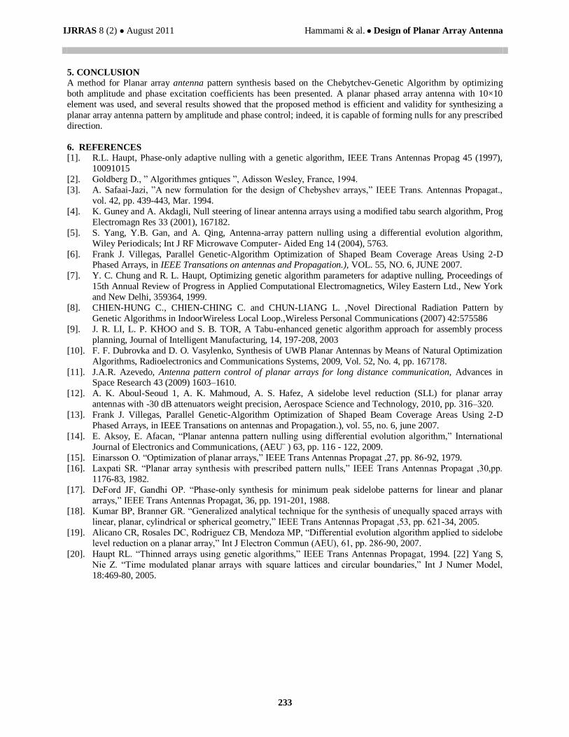
Figure 7. Planar antenna array pattern with main beam at (φ=-30,θ=40°) and one null at (φ=20°,θ=90°)
Figure 8. Planar antenna array pattern with main beam at (φ=-30,θ=40°) and one null at (φ=20°,θ=90°)
-150 -100 -50 0 50 100 150
-80
-70
-60
-50
-40
-30
-20
-10
0
(°)
Am
pli
tud
e
(dB
)
=40° =90°
desired signal @-30 °
interference
IJRRAS 8 (2) ● August 2011 Hammami & al. ● Design of Planar Array Antenna
233
5. CONCLUSION
A method for Planar array antenna pattern synthesis based on the Chebytchev-Genetic Algorithm by optimizing
both amplitude and phase excitation coefficients has been presented. A planar phased array antenna with 10×10
element was used, and several results showed that the proposed method is efficient and validity for synthesizing a
planar array antenna pattern by amplitude and phase control; indeed, it is capable of forming nulls for any prescribed
direction.
6. REFERENCES
[1]. R.L. Haupt, Phase-only adaptive nulling with a genetic algorithm, IEEE Trans Antennas Propag 45 (1997),
10091015
[2]. Goldberg D., ” Algorithmes gntiques ”, Adisson Wesley, France, 1994.
[3]. A. Safaai-Jazi, ”A new formulation for the design of Chebyshev arrays,” IEEE Trans. Antennas Propagat.,
vol. 42, pp. 439-443, Mar. 1994.
[4]. K. Guney and A. Akdagli, Null steering of linear antenna arrays using a modified tabu search algorithm, Prog
Electromagn Res 33 (2001), 167182.
[5]. S. Yang, Y.B. Gan, and A. Qing, Antenna-array pattern nulling using a differential evolution algorithm,
Wiley Periodicals; Int J RF Microwave Computer- Aided Eng 14 (2004), 5763.
[6]. Frank J. Villegas, Parallel Genetic-Algorithm Optimization of Shaped Beam Coverage Areas Using 2-D Phased Arrays, in IEEE Transations on antennas and Propagation.), VOL. 55, NO. 6, JUNE 2007.
[7]. Y. C. Chung and R. L. Haupt, Optimizing genetic algorithm parameters for adaptive nulling, Proceedings of
15th Annual Review of Progress in Applied Computational Electromagnetics, Wiley Eastern Ltd., New York
and New Delhi, 359364, 1999.
[8]. CHIEN-HUNG C., CHIEN-CHING C. and CHUN-LIANG L. ,Novel Directional Radiation Pattern by
Genetic Algorithms in IndoorWireless Local Loop.,Wireless Personal Communications (2007) 42:575586
[9]. J. R. LI, L. P. KHOO and S. B. TOR, A Tabu-enhanced genetic algorithm approach for assembly process
planning, Journal of Intelligent Manufacturing, 14, 197-208, 2003
[10]. F. F. Dubrovka and D. O. Vasylenko, Synthesis of UWB Planar Antennas by Means of Natural Optimization
Algorithms, Radioelectronics and Communications Systems, 2009, Vol. 52, No. 4, pp. 167178.
[11]. J.A.R. Azevedo, Antenna pattern control of planar arrays for long distance communication, Advances in Space Research 43 (2009) 1603–1610.
[12]. A. K. Aboul-Seoud 1, A. K. Mahmoud, A. S. Hafez, A sidelobe level reduction (SLL) for planar array
antennas with -30 dB attenuators weight precision, Aerospace Science and Technology, 2010, pp. 316–320.
[13]. Frank J. Villegas, Parallel Genetic-Algorithm Optimization of Shaped Beam Coverage Areas Using 2-D
Phased Arrays, in IEEE Transations on antennas and Propagation.), vol. 55, no. 6, june 2007.
[14]. E. Aksoy, E. Afacan, “Planar antenna pattern nulling using differential evolution algorithm,” International
Journal of Electronics and Communications, (AEU¨ ) 63, pp. 116 - 122, 2009.
[15]. Einarsson O. “Optimization of planar arrays,” IEEE Trans Antennas Propagat ,27, pp. 86-92, 1979.
[16]. Laxpati SR. “Planar array synthesis with prescribed pattern nulls,” IEEE Trans Antennas Propagat ,30,pp.
1176-83, 1982.
[17]. DeFord JF, Gandhi OP. “Phase-only synthesis for minimum peak sidelobe patterns for linear and planar
arrays,” IEEE Trans Antennas Propagat, 36, pp. 191-201, 1988. [18]. Kumar BP, Branner GR. “Generalized analytical technique for the synthesis of unequally spaced arrays with
linear, planar, cylindrical or spherical geometry,” IEEE Trans Antennas Propagat ,53, pp. 621-34, 2005.
[19]. Alicano CR, Rosales DC, Rodriguez CB, Mendoza MP, “Differential evolution algorithm applied to sidelobe
level reduction on a planar array,” Int J Electron Commun (AEU), 61, pp. 286-90, 2007.
[20]. Haupt RL. “Thinned arrays using genetic algorithms,” IEEE Trans Antennas Propagat, 1994. [22] Yang S,
Nie Z. “Time modulated planar arrays with square lattices and circular boundaries,” Int J Numer Model,
18:469-80, 2005.