Embed Size (px)
Citation preview
E-Mobility Solutions
Automotive connection- October 2019
Contacts:
Marc SECRETIN 0658082247
Michel MAZZOLA
Comment améliorer les échanges emotor-batterie, l‘optimisation des
rendements et l‘éfficacité des véhicules grace à des solutions innovantes
de mesure et de moyens d‘essais.

Factsimc Test & Measurement GmbH
28.10.2019 © imc Meßsysteme GmbH2
• Founded in 1988
• Head office and production in Berlin, Germany
• Subsidiaries in China, Austria, Switzerland, France, Benelux and USA
• Approximately 200 employees (thereof ca. 60% developers and
engineers)
• Cooperation with 25 companies in 28 countries
• More than 100 patents
Management: imc Berlin & Frankfurt

What is our business?
28.10.2019 © imc Meßsysteme GmbH3
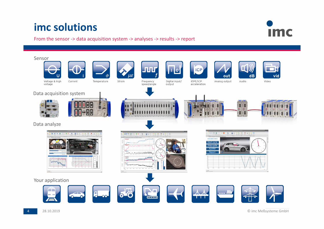
imc solutionsFrom the sensor -> data acquisition system -> analyses -> results -> report
28.10.2019 © imc Meßsysteme GmbH4
Sensor
Data acquisition system
Data analyze
Your application
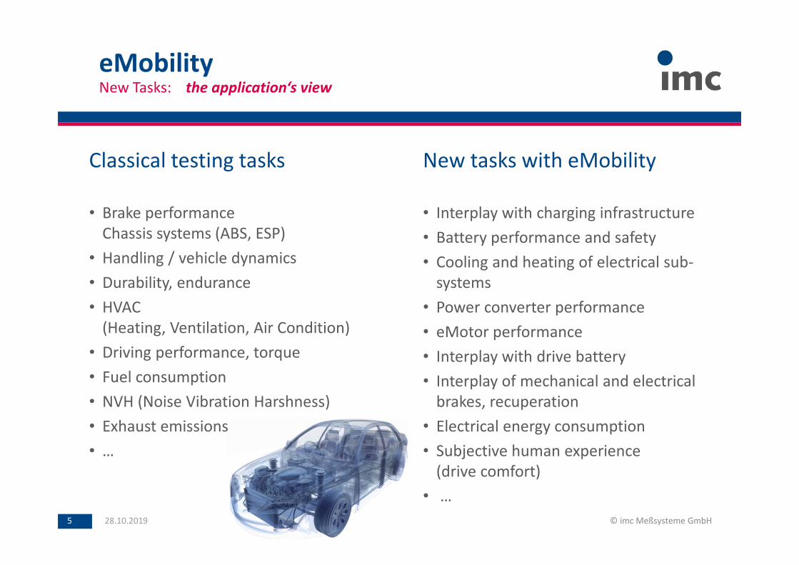
eMobilityNew Tasks: the application‘s view
28.10.2019 © imc Meßsysteme GmbH5
Classical testing tasks
• Brake performance
Chassis systems (ABS, ESP)
• Handling / vehicle dynamics
• Durability, endurance
• HVAC
(Heating, Ventilation, Air Condition)
• Driving performance, torque
• Fuel consumption
• NVH (Noise Vibration Harshness)
• Exhaust emissions
• …
New tasks with eMobility
• Interplay with charging infrastructure
• Battery performance and safety
• Cooling and heating of electrical sub-
systems
• Power converter performance
• eMotor performance
• Interplay with drive battery
• Interplay of mechanical and electrical
brakes, recuperation
• Electrical energy consumption
• Subjective human experience
(drive comfort)
• …
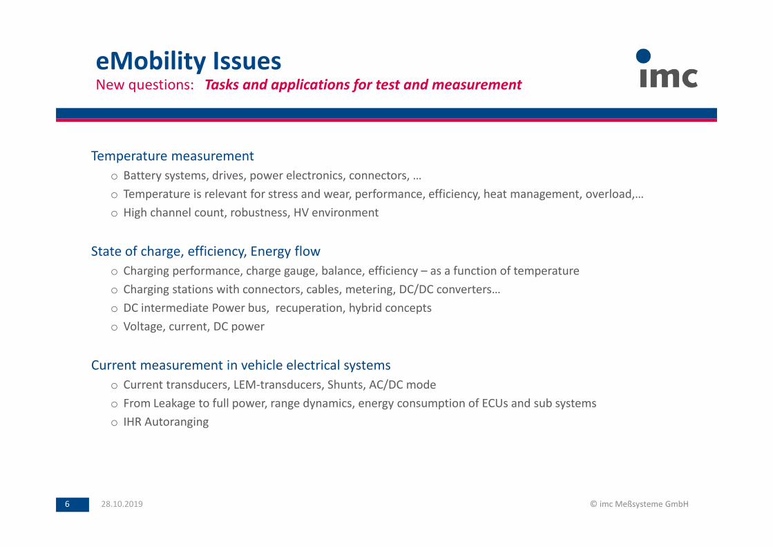
Temperature measurement
o Battery systems, drives, power electronics, connectors, …
o Temperature is relevant for stress and wear, performance, efficiency, heat management, overload,…
o High channel count, robustness, HV environment
State of charge, efficiency, Energy flow
o Charging performance, charge gauge, balance, efficiency – as a function of temperature
o Charging stations with connectors, cables, metering, DC/DC converters…
o DC intermediate Power bus, recuperation, hybrid concepts
o Voltage, current, DC power
Current measurement in vehicle electrical systems
o Current transducers, LEM-transducers, Shunts, AC/DC mode
o From Leakage to full power, range dynamics, energy consumption of ECUs and sub systems
o IHR Autoranging
eMobility IssuesNew questions: Tasks and applications for test and measurement
28.10.2019 © imc Meßsysteme GmbH6
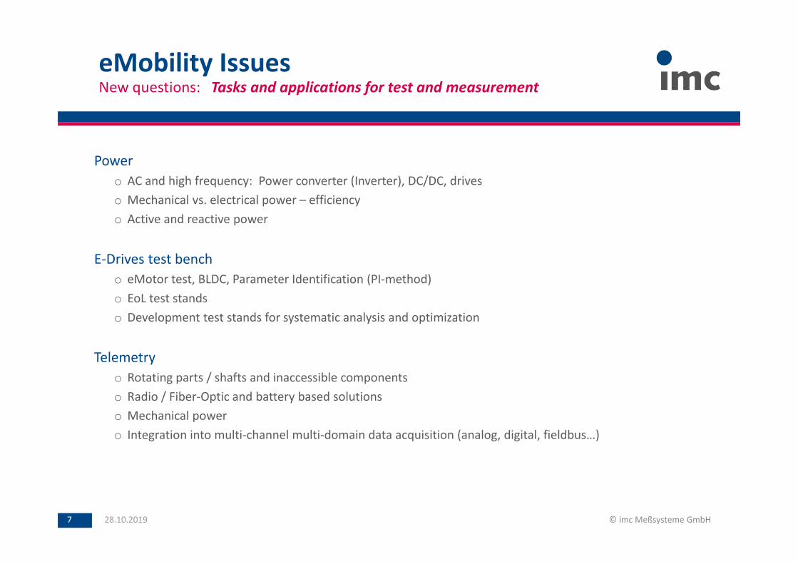
Power
o AC and high frequency: Power converter (Inverter), DC/DC, drives
o Mechanical vs. electrical power – efficiency
o Active and reactive power
E-Drives test bench
o eMotor test, BLDC, Parameter Identification (PI-method)
o EoL test stands
o Development test stands for systematic analysis and optimization
Telemetry
o Rotating parts / shafts and inaccessible components
o Radio / Fiber-Optic and battery based solutions
o Mechanical power
o Integration into multi-channel multi-domain data acquisition (analog, digital, fieldbus…)
eMobility IssuesNew questions: Tasks and applications for test and measurement
28.10.2019 © imc Meßsysteme GmbH7
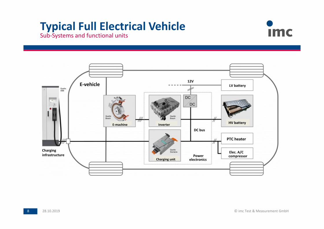
Typical Full Electrical Vehicle
28.10.2019 © imc Test & Measurement GmbH8
Charging unit
InverterE-machine
E-vehicle
HV battery
PTC heater
compressorElec. A/C
LV battery
electronicsPower
12V
DC bus
infrastructure
Charging
Sub-Systems and functional units
Charging
unit
InverterE-machine
E-vehicle
HV
battery
PTC
heater
compressorElec. A/C
LV battery
electronics
Power
12V
DC
bus
infrastructure
Charging
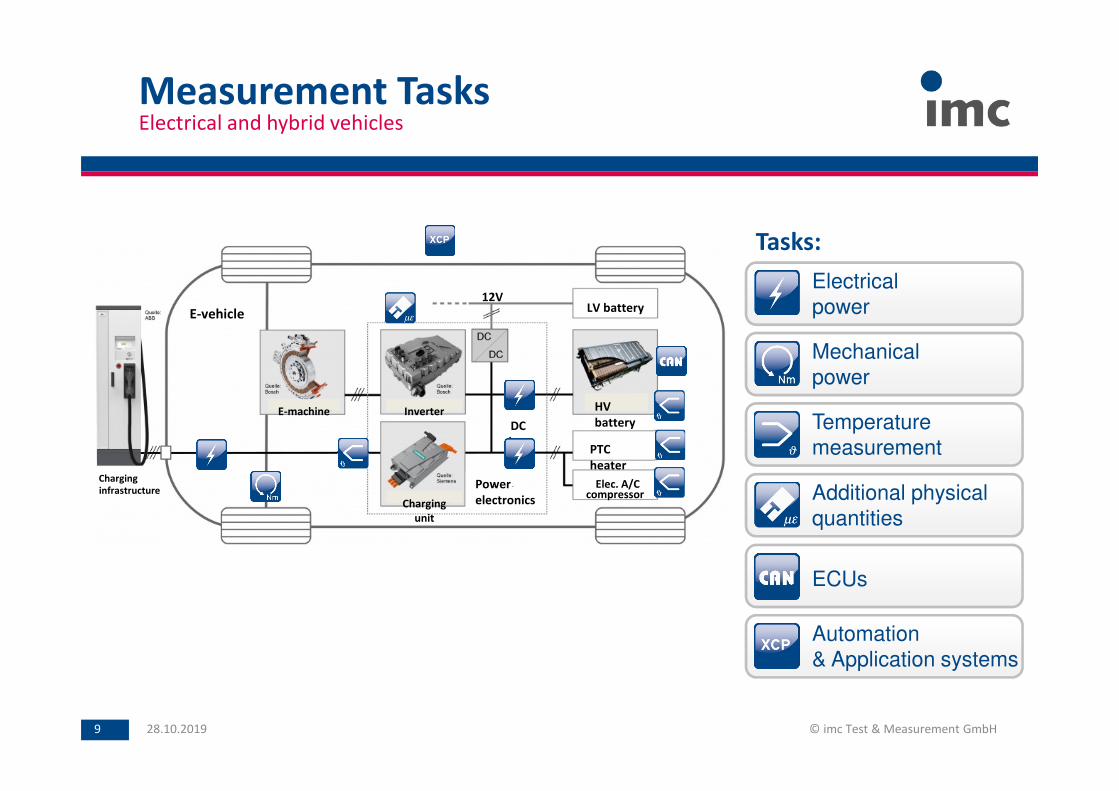
Measurement Tasks
28.10.2019 © imc Test & Measurement GmbH9
Electrical and hybrid vehicles
Tasks:
Electrical
power
Mechanical
power
Temperature
measurement
Additional physical
quantities
ECUs
Automation
& Application systems
E-Mobility Solutions
Solutions for current measurement with LEM transducers
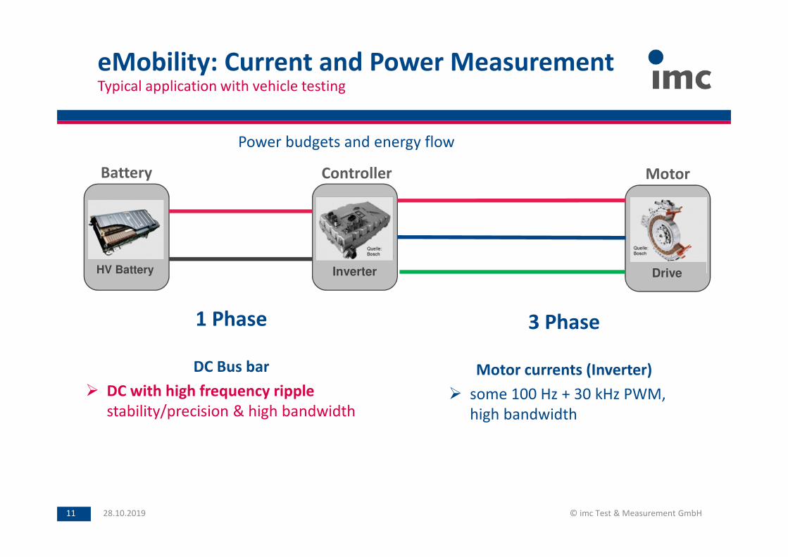
eMobility: Current and Power MeasurementTypical application with vehicle testing
28.10.2019 © imc Test & Measurement GmbH11
Battery MotorController
InverterHV Battery Drive
Power budgets and energy flow
3 Phase
Motor currents (Inverter)
some 100 Hz + 30 kHz PWM,
high bandwidth
1 Phase
DC Bus bar
DC with high frequency ripple
stability/precision & high bandwidth
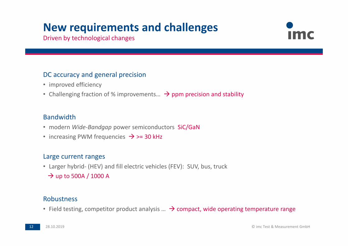
DC accuracy and general precision
• improved efficiency
• Challenging fraction of % improvements… ppm precision and stability
Bandwidth
• modern Wide-Bandgap power semiconductors SiC/GaN
• increasing PWM frequencies >= 30 kHz
Large current ranges
• Larger hybrid- (HEV) and fill electric vehicles (FEV): SUV, bus, truck
up to 500A / 1000 A
Robustness
• Field testing, competitor product analysis … compact, wide operating temperature range
New requirements and challengesDriven by technological changes
28.10.2019 © imc Test & Measurement GmbH12
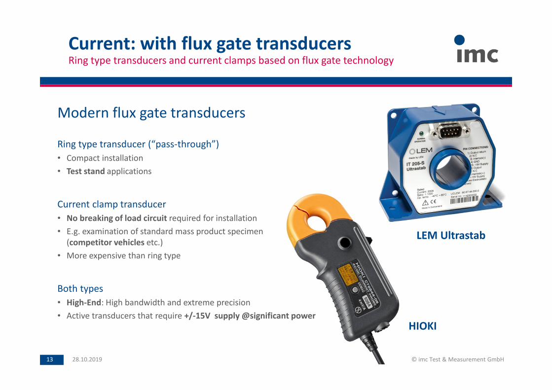
Current: with flux gate transducersRing type transducers and current clamps based on flux gate technology
28.10.2019 © imc Test & Measurement GmbH13
Modern flux gate transducers
Ring type transducer (“pass-through”)
• Compact installation
• Test stand applications
Current clamp transducer
• No breaking of load circuit required for installation
• E.g. examination of standard mass product specimen
(competitor vehicles etc.)
• More expensive than ring type
Both types
• High-End: High bandwidth and extreme precision
• Active transducers that require +/-15V supply @significant power
LEM Ultrastab
HIOKI
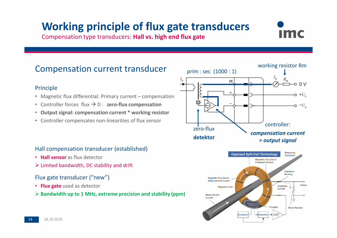
Working principle of flux gate transducersCompensation type transducers: Hall vs. high end flux gate
28.10.2019 © imc Test & Measurement GmbH14
Compensation current transducer
Principle
• Magnetic flux differential: Primary current – compensation
• Controller forces flux 0 : zero-flux compensation
• Output signal: compensation current * working resistor
• Controller compensates non-linearities of flux sensor
Hall compensation transducer (established)
• Hall sensor as flux detector
Limited bandwidth, DC stability and drift
Flux gate transducer (“new”)
• Flux gate used as detector
Bandwidth up to 1 MHz, extreme precision and stability (ppm)
zero-flux
detektor
prim : sec (1000 : 1)working resistor Rm
controller:
compensation current
= output signal
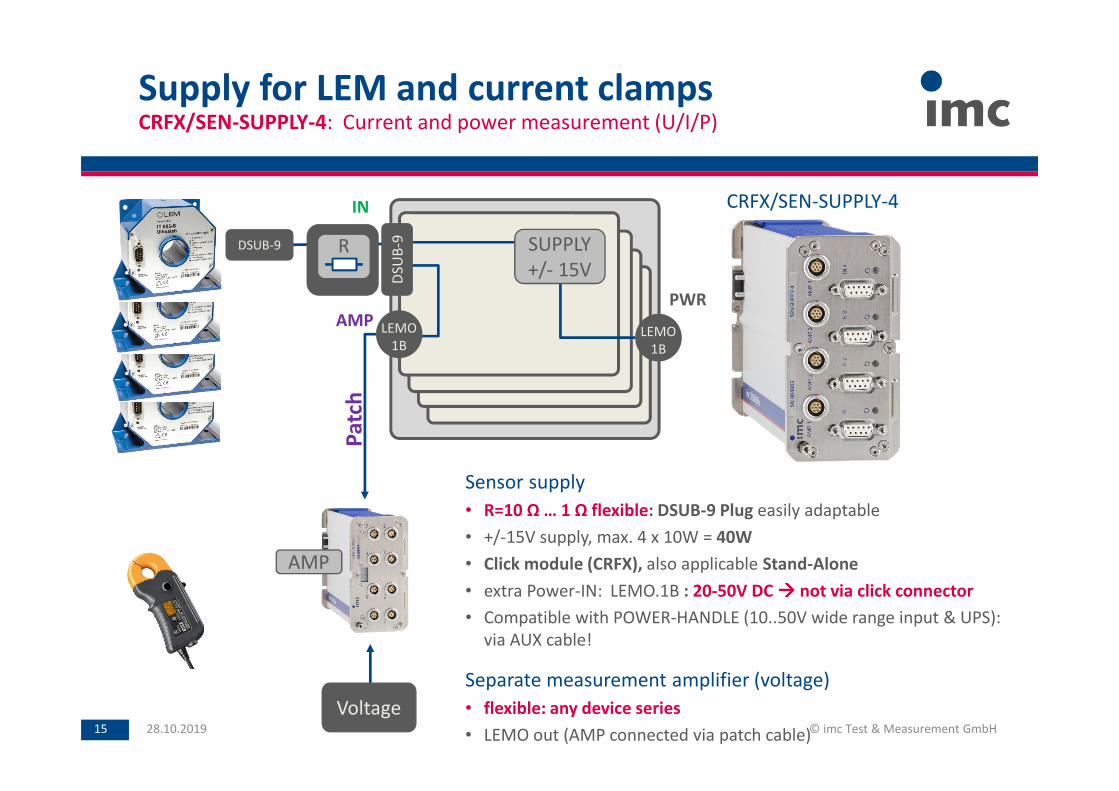
Sensor supply
• R=10 Ω … 1 Ω flexible: DSUB-9 Plug easily adaptable
• +/-15V supply, max. 4 x 10W = 40W
• Click module (CRFX), also applicable Stand-Alone
• extra Power-IN: LEMO.1B : 20-50V DC not via click connector
• Compatible with POWER-HANDLE (10..50V wide range input & UPS):
via AUX cable!
Separate measurement amplifier (voltage)
• flexible: any device series
• LEMO out (AMP connected via patch cable)
DSUB-9
Supply for LEM and current clampsCRFX/SEN-SUPPLY-4: Current and power measurement (U/I/P)
28.10.2019 © imc Test & Measurement GmbH15
LEMO
1BLEMO
1B
R
DS
UB
-9
CRFX/SEN-SUPPLY-4
SUPPLY
+/- 15V
Voltage
AMP
Pa
tch
AMP
IN
PWR
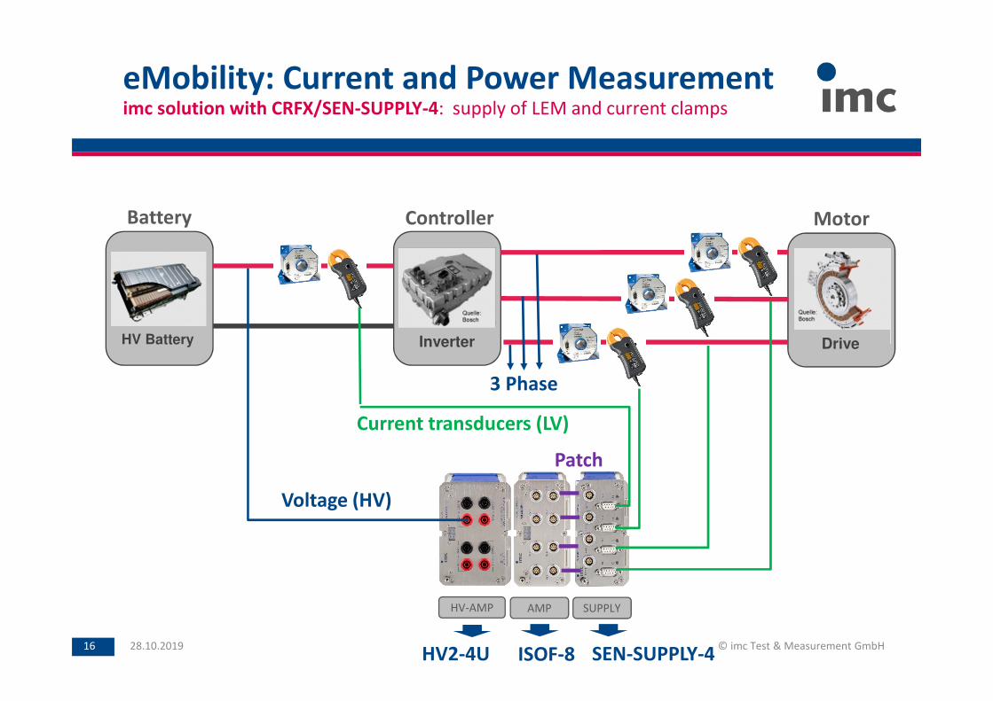
eMobility: Current and Power Measurementimc solution with CRFX/SEN-SUPPLY-4: supply of LEM and current clamps
28.10.2019 © imc Test & Measurement GmbH16
AMP SUPPLY
Voltage (HV)
Current transducers (LV)
Patch
3 Phase
HV-AMP
HV2-4U ISOF-8 SEN-SUPPLY-4
Battery MotorController
InverterHV Battery Drive
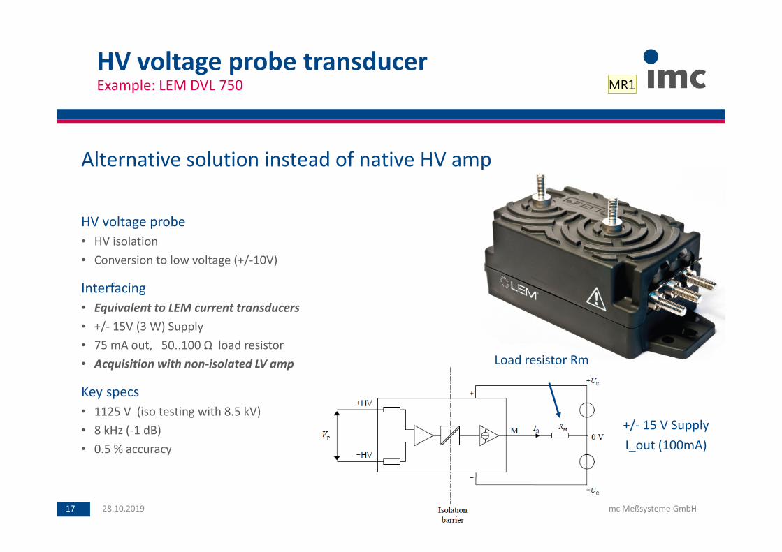
HV voltage probe transducerExample: LEM DVL 750
28.10.2019 © imc Meßsysteme GmbH17
+/- 15 V Supply
I_out (100mA)
Load resistor Rm
Alternative solution instead of native HV amp
HV voltage probe
• HV isolation
• Conversion to low voltage (+/-10V)
Interfacing
• Equivalent to LEM current transducers
• +/- 15V (3 W) Supply
• 75 mA out, 50..100 Ω load resistor
• Acquisition with non-isolated LV amp
Key specs
• 1125 V (iso testing with 8.5 kV)
• 8 kHz (-1 dB)
• 0.5 % accuracy
MR1

Diapositive 17
MR1 Martin Riedel; 27/08/2018

eMobility: Current and Power Measurementimc solution with CRFX/SEN-SUPPLY-4: supply of LEM and current clamps
28.10.2019 © imc Test & Measurement GmbH18
AMP SUPPLY
Voltage (HV)
Current transducers (LV)
Patch
3 Phase
HV-AMP
HV2-4U ISOF-8 SEN-SUPPLY-4
Battery MotorController
InverterHV Battery Drive
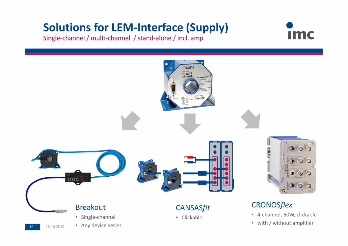
Solutions for LEM-Interface (Supply)Single-channel / multi-channel / stand-alone / incl. amp
28.10.2019 © imc Meßsysteme GmbH19
Breakout• Single-channel
• Any device series
CANSASfit
• Clickable
CRONOSflex
• 4-channel, 60W, clickable
• with / without amplifier
Electric system testing by using breadboard car
The imc IHR module
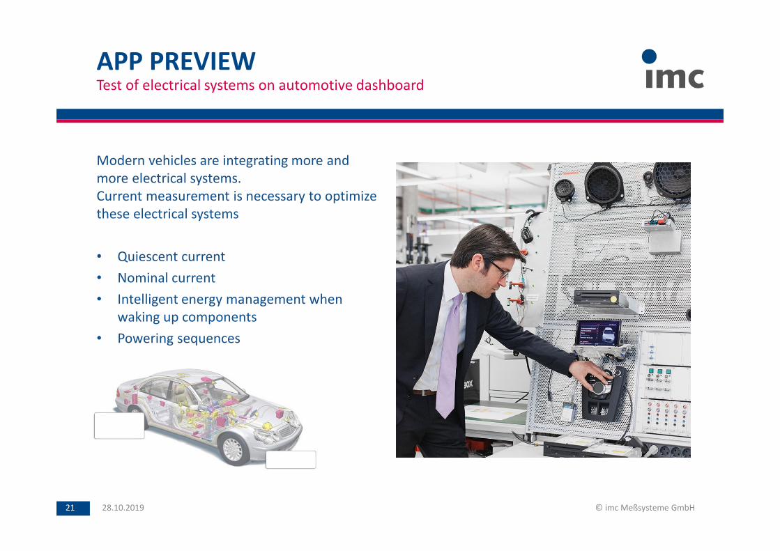
APP PREVIEWTest of electrical systems on automotive dashboard
Modern vehicles are integrating more and
more electrical systems.
Current measurement is necessary to optimize
these electrical systems
• Quiescent current
• Nominal current
• Intelligent energy management when
waking up components
• Powering sequences
28.10.2019 © imc Meßsysteme GmbH21
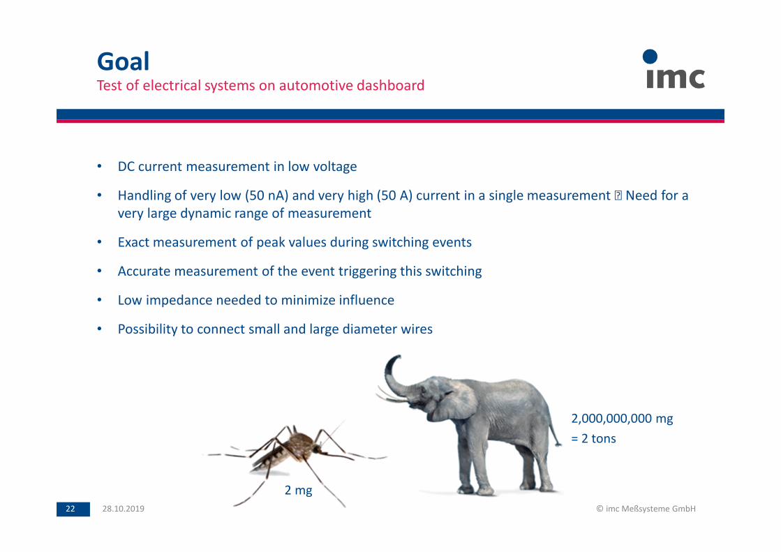
• DC current measurement in low voltage
• Handling of very low (50 nA) and very high (50 A) current in a single measurement Need for a
very large dynamic range of measurement
• Exact measurement of peak values during switching events
• Accurate measurement of the event triggering this switching
• Low impedance needed to minimize influence
• Possibility to connect small and large diameter wires
GoalTest of electrical systems on automotive dashboard
28.10.2019 © imc Meßsysteme GmbH22
2 mg
2,000,000,000 mg
= 2 tons

Summaryimc IHR
• Slides on a backplane in 19” rack
• Backplane has high-current terminals (solder or spring)
• Output on CAN bus integration into any
measurement/control system easy
• Output rate 1 Hz or 10 Hz
• Internal sampling rate 30 kHz
• Shunt switching within 1 µs / 1 ms
• Max. current slope 10 A/µs
• Output information:
• Average of each interval
• Min & max in each interval
• Location of peaks in interval
28.10.2019 © imc Meßsysteme GmbH23
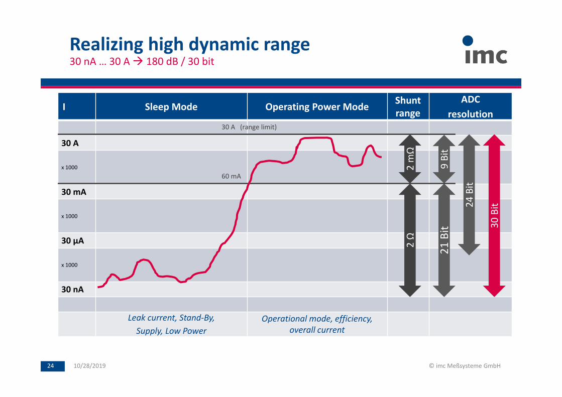
Realizing high dynamic range30 nA … 30 A 180 dB / 30 bit
10/28/2019 © imc Meßsysteme GmbH24
I Sleep Mode Operating Power ModeShunt
range
ADC
resolution
30 A
x 1000
30 mA
x 1000
30 µA
x 1000
30 nA
Leak current, Stand-By,
Supply, Low Power
Operational mode, efficiency,
overall current
2 m
Ω2
Ω
21
Bit
24
Bit
30
Bit
9 B
it
60 mA
30 A (range limit)
E-Mobility Solutions
Solutions with telemetry
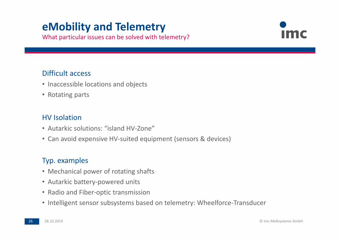
Difficult access
• Inaccessible locations and objects
• Rotating parts
HV Isolation
• Autarkic solutions: “island HV-Zone”
• Can avoid expensive HV-suited equipment (sensors & devices)
Typ. examples
• Mechanical power of rotating shafts
• Autarkic battery-powered units
• Radio and Fiber-optic transmission
• Intelligent sensor subsystems based on telemetry: Wheelforce-Transducer
eMobility and TelemetryWhat particular issues can be solved with telemetry?
28.10.2019 © imc Meßsysteme GmbH26
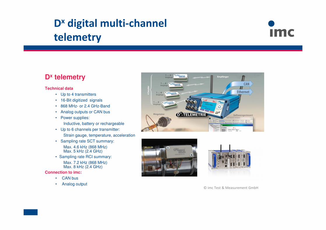
Dx digital multi-channel
telemetry
Dx telemetry
Technical data
• Up to 4 transmitters
• 16-Bit digitized signals
• 868 MHz- or 2.4 GHz-Band
• Analog outputs or CAN bus
• Power supplies:
Inductive, battery or rechargeable
• Up to 6 channels per transmitter:
Strain gauge, temperature, acceleration
• Sampling rate SCT summary:
Max. 4.6 kHz (868 MHz)Max. 5 kHz (2.4 GHz)
• Sampling rate RCI summary:
Max. 7.2 kHz (868 MHz)Max. 8 kHz (2.4 GHz)
Connection to imc:
• CAN bus
• Analog output© imc Test & Measurement GmbH
28.10.2019 © CAEMAX Technologie GmbH28
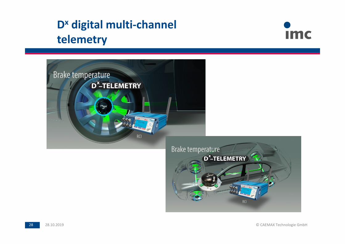
Dx digital multi-channel
telemetry
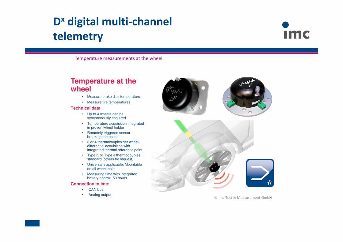
Temperature at the wheel
• Measure brake disc temperature
• Measure tire temperatures
Technical data
• Up to 4 wheels can be synchronously acquired
• Temperature acquisition integrated in proven wheel holder
• Remotely triggered sensor breakage detection
• 3 or 4 thermocouples per wheel, differential acquisition with integrated thermal reference point
• Type K or Type J thermocouples standard (others by request)
• Universally applicable. Mountable
on all wheel bolts.
• Measuring time with integrated battery approx. 50 hours
Connection to imc:
• CAN bus
• Analog output© imc Test & Measurement GmbH
Dx digital multi-channel
telemetry
Temperature measurements at the wheel
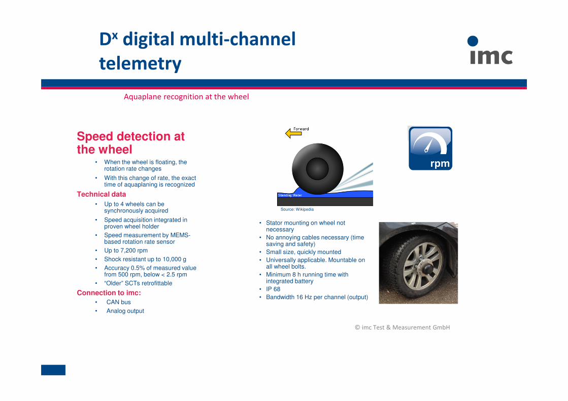
Speed detection at the wheel
• When the wheel is floating, the rotation rate changes
• With this change of rate, the exact time of aquaplaning is recognized
Technical data
• Up to 4 wheels can be synchronously acquired
• Speed acquisition integrated in proven wheel holder
• Speed measurement by MEMS-based rotation rate sensor
• Up to 7,200 rpm
• Shock resistant up to 10,000 g
• Accuracy 0.5% of measured value from 500 rpm, below < 2.5 rpm
• “Older” SCTs retrofittable
Connection to imc:
• CAN bus
• Analog output
© imc Test & Measurement GmbH
Dx digital multi-channel
telemetry
Aquaplane recognition at the wheel
• Stator mounting on wheel not necessary
• No annoying cables necessary (time saving and safety)
• Small size, quickly mounted
• Universally applicable. Mountable on all wheel bolts.
• Minimum 8 h running time with integrated battery
• IP 68
• Bandwidth 16 Hz per channel (output)
Source: Wikipedia
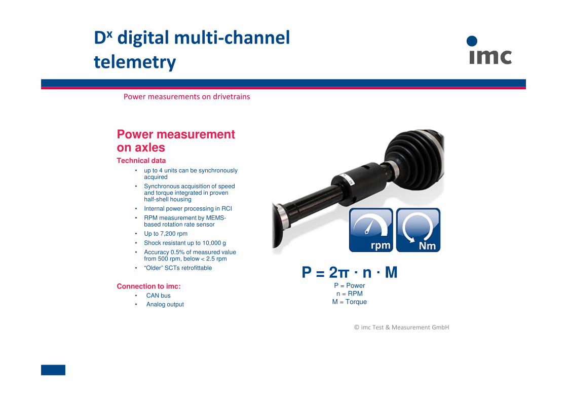
Power measurementon axlesTechnical data
• up to 4 units can be synchronously acquired
• Synchronous acquisition of speed and torque integrated in proven half-shell housing
• Internal power processing in RCI
• RPM measurement by MEMS-based rotation rate sensor
• Up to 7,200 rpm
• Shock resistant up to 10,000 g
• Accuracy 0.5% of measured value from 500 rpm, below < 2.5 rpm
• “Older” SCTs retrofittable
Connection to imc:
• CAN bus
• Analog output
© imc Test & Measurement GmbH
Dx digital multi-channel
telemetry
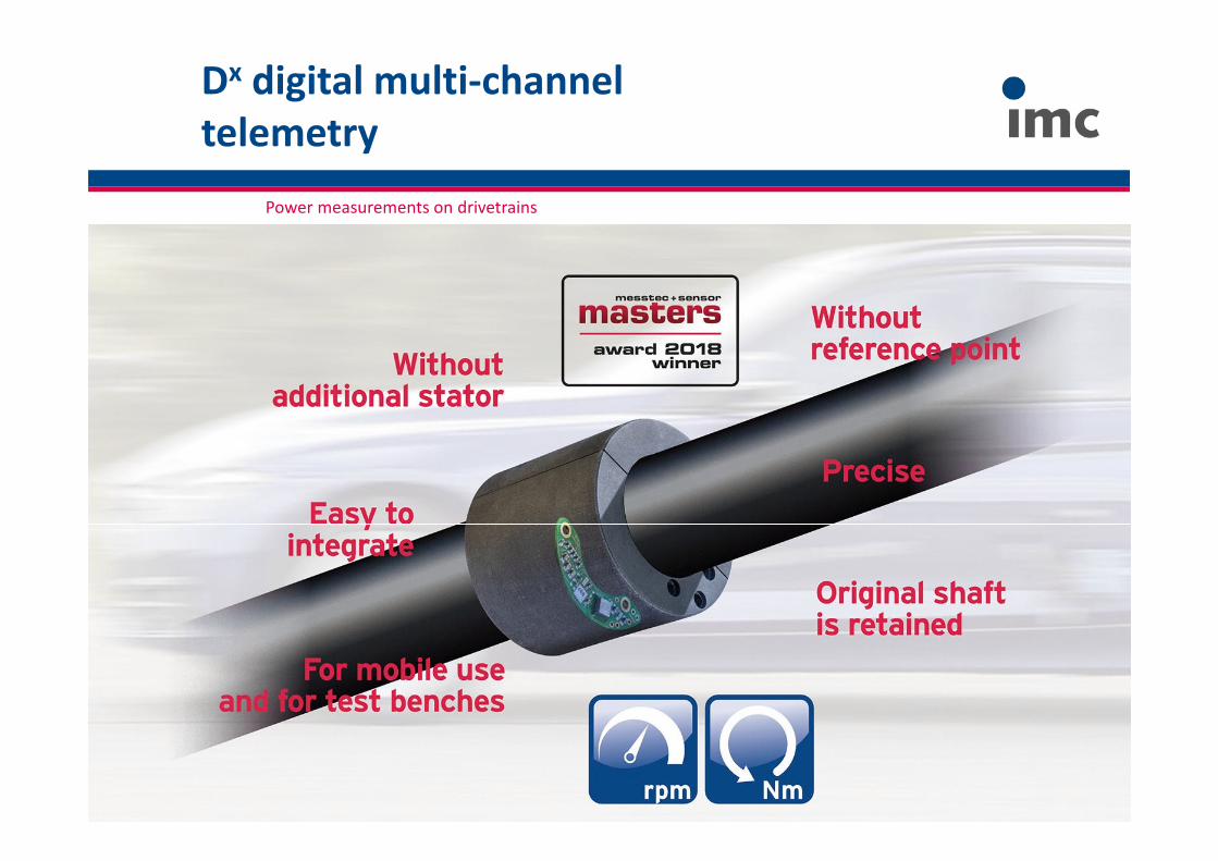
Power measurements on drivetrains
P = 2π · n · MP = Power
n = RPM
M = Torque
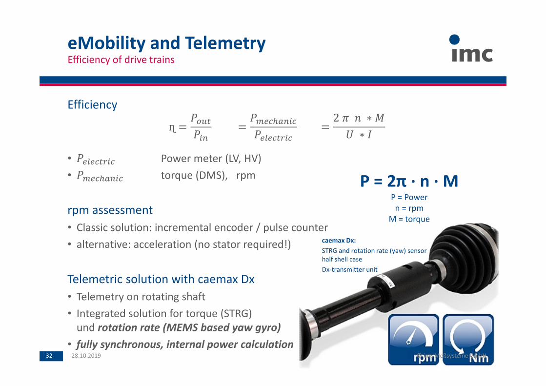
Efficiency
ɳ =
=
=
2 ∗
∗
• Power meter (LV, HV)
• torque (DMS), rpm
rpm assessment
• Classic solution: incremental encoder / pulse counter
• alternative: acceleration (no stator required!)
Telemetric solution with caemax Dx
• Telemetry on rotating shaft
• Integrated solution for torque (STRG)
und rotation rate (MEMS based yaw gyro)
• fully synchronous, internal power calculation
eMobility and TelemetryEfficiency of drive trains
28.10.2019 © imc Meßsysteme GmbH32
caemax Dx:
STRG and rotation rate (yaw) sensor
half shell case
Dx-transmitter unit
P = 2π ∙ n ∙ MP = Power
n = rpm
M = torque
© imc Test & Measurement GmbH
Dx digital multi-channel
telemetry
Power measurements on drivetrains
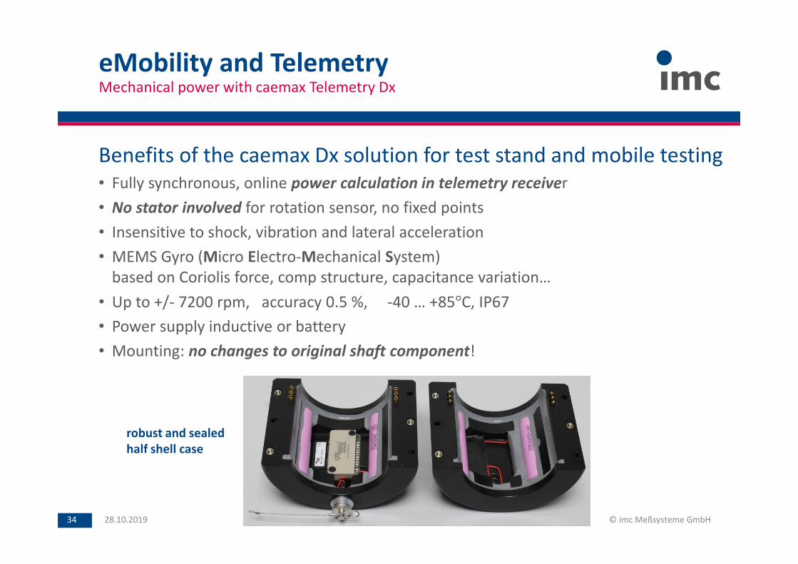
eMobility and TelemetryMechanical power with caemax Telemetry Dx
28.10.2019 © imc Meßsysteme GmbH34
Benefits of the caemax Dx solution for test stand and mobile testing
• Fully synchronous, online power calculation in telemetry receiver
• No stator involved for rotation sensor, no fixed points
• Insensitive to shock, vibration and lateral acceleration
• MEMS Gyro (Micro Electro-Mechanical System)
based on Coriolis force, comp structure, capacitance variation…
• Up to +/- 7200 rpm, accuracy 0.5 %, -40 … +85°C, IP67
• Power supply inductive or battery
• Mounting: no changes to original shaft component!
robust and sealed
half shell case

Thanks for your attention!
More information: www.imc-france.com