Embed Size (px)
Citation preview
564 Motors and controls Motors for linear axes
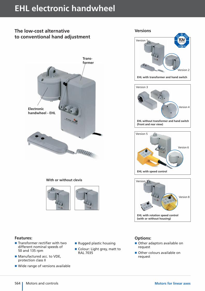
EHL electronic handwheel
Features: � Transformer rectifier with two different nominal speeds of 50 and 135 rpm
� Manufactured acc. to VDE, protection class II
� Wide range of versions available
Options: � Other adaptors available on request
� Other colours available on request
The low-cost alternative to conventional hand adjustment
Electronic handwheel - EHL
Trans-former
Versions
With or without clevis
EHL with transformer and hand switch
Version 1
Version 2
EHL without transformer and hand switch(Front and rear view)
Version 3
Version 4
EHL with speed control
Version 5
Version 6
EHL with rotation speed control(with or without housing)
Version 7
Version 8
� Rugged plastic housing
� Colour: Light grey, matt to RAL 7035
565Motors and controls
Mo
ve-T
ecPl
ace-
Tec
Co
ntr
ol-
Tec
Intr
od
uct
ion
Sele
ctio
n a
idA
pp
end
ixM
od
ule
sM
oto
rs/
Co
ntr
ols
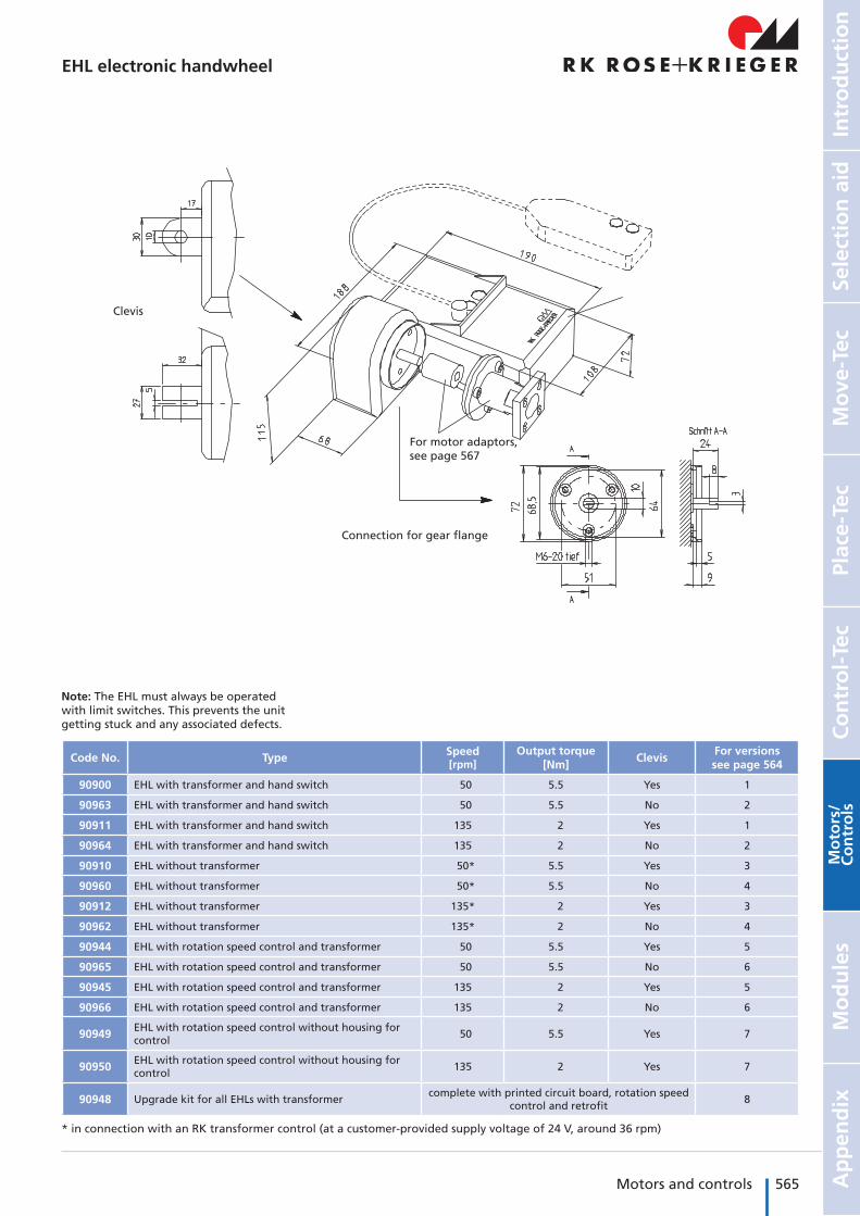
EHL electronic handwheel
Code No. Type Speed [rpm]
Output torque [Nm]
ClevisFor versions see page 564
90900 EHL with transformer and hand switch 50 5.5 Yes 1
90963 EHL with transformer and hand switch 50 5.5 No 2
90911 EHL with transformer and hand switch 135 2 Yes 1
90964 EHL with transformer and hand switch 135 2 No 2
90910 EHL without transformer 50* 5.5 Yes 3
90960 EHL without transformer 50* 5.5 No 4
90912 EHL without transformer 135* 2 Yes 3
90962 EHL without transformer 135* 2 No 4
90944 EHL with rotation speed control and transformer 50 5.5 Yes 5
90965 EHL with rotation speed control and transformer 50 5.5 No 6
90945 EHL with rotation speed control and transformer 135 2 Yes 5
90966 EHL with rotation speed control and transformer 135 2 No 6
90949 EHL with rotation speed control without housing for control
50 5.5 Yes 7
90950 EHL with rotation speed control without housing for control
135 2 Yes 7
90948 Upgrade kit for all EHLs with transformercomplete with printed circuit board, rotation speed
control and retrofit8
Clevis
Connection for gear flange
For motor adaptors, see page 567
Note: The EHL must always be operated with limit switches. This prevents the unit getting stuck and any associated defects.
* in connection with an RK transformer control (at a customer-provided supply voltage of 24 V, around 36 rpm)
566 Motors and controls Motors for linear axes
EHL – Technical data/fixing
General information/operating conditions
Duty cycle 100 %
Starting torque 5.5 Nm at 50 rpm/2 Nm at 135 rpm
Thermal protection 115 °C
Protection class IP 20
Rotation speed control Electronic, infinitely variable adjustment using a rotary potentiometer
Fast mode Operating mode with nominal speed (50 or 135 rpm), rotary potentiometer without function
Creep mode Infinitely variable speed adjustment using a rotary potentiometer
Drive set-up Can be rotated in 90°increments – connecting cable must be extended
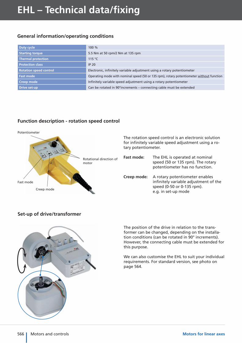
Function description - rotation speed control
Set-up of drive/transformer
Rotational direction of motor
Fast mode
Creep mode
Potentiometer
The rotation speed control is an electronic solution for infinitely variable speed adjustment using a ro-tary potentiometer.
Fast mode: The EHL is operated at nominal speed (50 or 135 rpm). The rotary potentiometer has no function.
Creep mode: A rotary potentiometer enables infinitely variable adjustment of the speed (0-50 or 0-135 rpm). e.g. in set-up mode
The position of the drive in relation to the trans-former can be changed, depending on the installa-tion conditions (can be rotated in 90° increments). However, the connecting cable must be extended for this purpose.
We can also customise the EHL to suit your individual requirements. For standard version, see photo on page 564.
567Motors and controls
Mo
ve-T
ecPl
ace-
Tec
Co
ntr
ol-
Tec
Intr
od
uct
ion
Sele
ctio
n a
idA
pp
end
ixM
od
ule
sM
oto
rs/
Co
ntr
ols
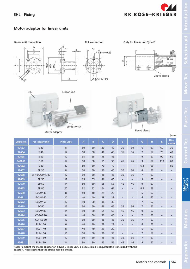
EHL Linear unit
Limit switch
Motor adaptor
Note: To mount the motor adaptor on a Type E linear unit, a sleeve clamp is required (this is included with the adaptor). Please note that the stroke may be limited.
Sleeve clamp
Motor adaptor for linear units
Sleeve clamp
7 (E/EP 80=6,5)51
26 (E/EP 80=34)
8
H
Ø68
,5Ø
64Ø
40
1272
G
ACE
B D F
Linear unit connection EHL connection Only for linear unit Type E
Code No. for linear unit PinØ unit A B C D E F G H LDia-
meter
92663 E 30 8 50 50 30 40 30 30 6 67 60 30
92664 E 40 12 60 60 46 46 36 36 7 67 75 40
92665 E 50 12 65 65 46 46 – – 9 67 90 60
949666 E 60 14 80 80 55 55 46 46 9 67 110 60
92682 E 80 20 80 80 70 70 – – 6.2 59 80
92667 EP 30 8 50 50 30 40 30 30 6 67 – –
92668 EP 40/COPAS 40 12 60 60 46 46 36 36 7 67 – –
92669 EP 50 12 65 65 46 46 – – 9 67 – –
92670 EP 60 14 80 80 55 55 46 46 9 67 – –
92683 EP 80 20 92 92 64 64 – – 8.5 59 –
92680 EV/AV 30 8 40 40 29 29 – – 6 67 – –
92671 EV/AV 40 10 40 40 29 29 – – 6 67 – –
92672 EV/AV 50 12 50 50 38 38 – – 7 67 – –
92679 EV 60 12 60 60 46 46 36 36 7 67 – –
92673 EV/AV 80 14 80 80 55 55 46 46 9 67 – –
92674 COPAS 20 8 46 50 30 40 – – 7 67 – –
92675 COPAS 30 10 60 60 46 46 36 36 7 67 – –
92676 PLS-II 30 6 40 40 29 29 – – 6 67 – –
92677 PLS-II 40 8 40 40 29 29 – – 6 67 – –
92678 PLS-II 50 10 50 50 38 38 – – 7 67 – –
92679 PLS-II 60 12 60 60 46 46 36 36 7 67 – –
92681 PLS-II 80 14 80 80 55 55 46 46 9 67 – –
[mm]
EHL - Fixing
568 Motors and controls Motors for linear axes
EHL – Position determination
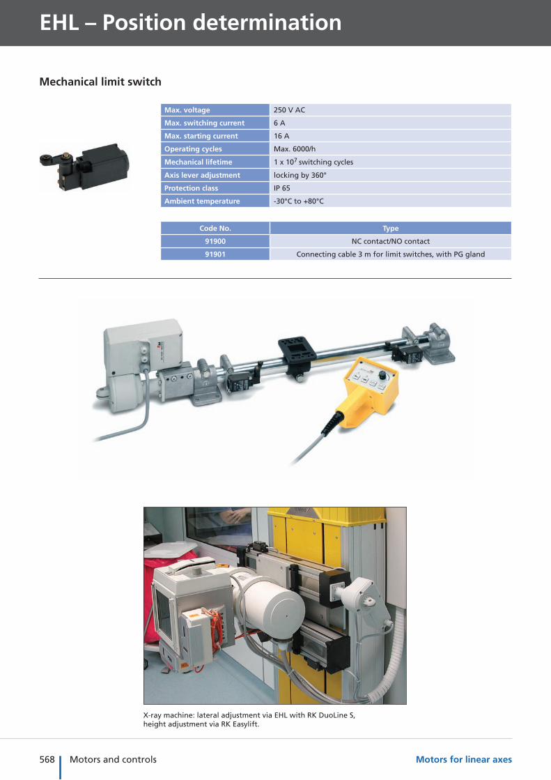
Max. voltage 250 V AC
Max. switching current 6 A
Max. starting current 16 A
Operating cycles Max. 6000/h
Mechanical lifetime 1 x 10⁷ switching cycles
Axis lever adjustment locking by 360°
Protection class IP 65
Ambient temperature -30°C to +80°C
Code No. Type
91900 NC contact/NO contact
91901 Connecting cable 3 m for limit switches, with PG gland
Mechanical limit switch
X-ray machine: lateral adjustment via EHL with RK DuoLine S, height adjustment via RK Easylift.
569Motors and controls
Mo
ve-T
ecPl
ace-
Tec
Co
ntr
ol-
Tec
Intr
od
uct
ion
Sele
ctio
n a
idA
pp
end
ixM
od
ule
sM
oto
rs/
Co
ntr
ols
Transfer system: drive for material feed.
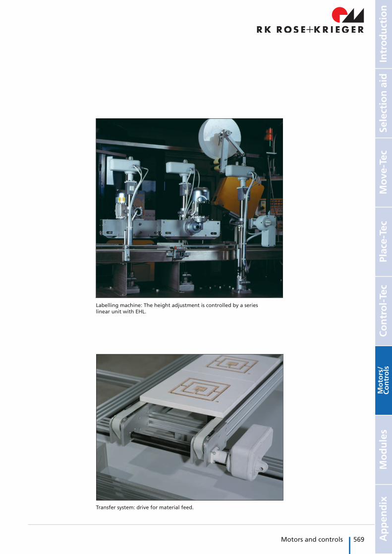
Labelling machine: The height adjustment is controlled by a series linear unit with EHL.
570 Motors and controls Motors for linear axes
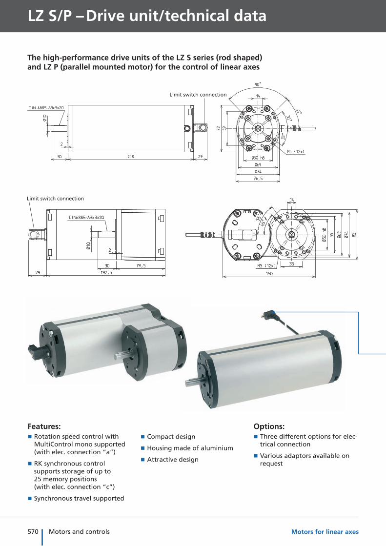
LZ S/P – Drive unit/technical data
The high-performance drive units of the LZ S series (rod shaped) and LZ P (parallel mounted motor) for the control of linear axes
Features: � Rotation speed control with MultiControl mono supported (with elec. connection “a”)
� RK synchronous control supports storage of up to 25 memory positions (with elec. connection “c”)
� Synchronous travel supported
Options: � Three different options for elec-trical connection
� Various adaptors available on request
Limit switch connection
Limit switch connection
� Compact design
� Housing made of aluminium
� Attractive design
571Motors and controls
Mo
ve-T
ecPl
ace-
Tec
Co
ntr
ol-
Tec
Intr
od
uct
ion
Sele
ctio
n a
idA
pp
end
ixM
od
ule
sM
oto
rs/
Co
ntr
ols
General information/operating conditions
Voltage 24-36 V DC
Current consumption Max. 4.5 A
Protection class IP 54
Ambient temperature -10°C to +60°C
Duty cycle at nominal load, 20% (max. 5 mins operating time, 20 mins rest time)
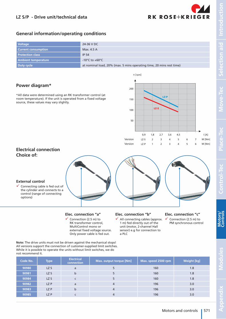
Power diagram*
*All data were determined using an RK transformer control (at room temperature). If the unit is operated from a fixed voltage source, these values may vary slightly.
rpm
External control 9 Connecting cable is fed out of
the cylinder and connects to a control (range of connecting options)
Elec. connection “a” 9 Connection (2.5 m) to
RK transformer control, MultiControl mono or external fixed voltage source. Only power cable is fed out.
Elec. connection “b” 9 All connecting cables (approx.
1 m) fed directly out of the unit (motor, 2-channel Hall sensor) e.g for connection to a PLC
Elec. connection “c” 9 Connection (2.5 m) to
PM synchronous control
Electrical connectionChoice of:
Code No. TypeElectrical
connectionMax. output torque [Nm] Max. speed 2500 rpm Weight [kg]
90980 LZ S a 5 160 1.8
90981 LZ S b 5 160 1.8
90984 LZ S c 5 160 1.8
90982 LZ P a 4 196 3.0
90983 LZ P b 4 196 3.0
90985 LZ P c 4 196 3.0
Note: The drive units must not be driven against the mechanical stops! All versions support the connection of customer-supplied limit switches. While it is possible to operate the units without limit switches, we do not recommend it.
Version
Version
LZ S/P - Drive unit/technical data
572 Motors and controls Motors for linear axes
Controls
LZ S/P – Drive
Transformer control 120 VA
approx. 24 V DC approx. 36 V DC
MultiControlFor dimensions and other technical data, please refer to the chapter “Motors and controls”
� Input voltage 230 V AC
� Output voltage 24/36 V AC
Code No. Version
QZA07C13BQ021 Transformer control 120 VA, up to max. I = 3 A current output at 10% duty cycle Controls up to 2 drives
QST35C01AA000RK MultiControl mono, up to max. I = 10 A current output at 15% duty cycle, 24/36 V DC
Controls up to 2 drives
QST35C02AA000*Synchronous control RK MultiControl duo, up to max. I = 12 A current output at 15% duty cycle
1-2 drives synchronised
QST35C04AA000*Synchronous control RK MultiControl quadro, up to max. I = 12 A current output at 15% duty cycle
1-4 drives synchronised
*For connection of a synchronous control, the drive unit must be fitted with electrical connection “c”
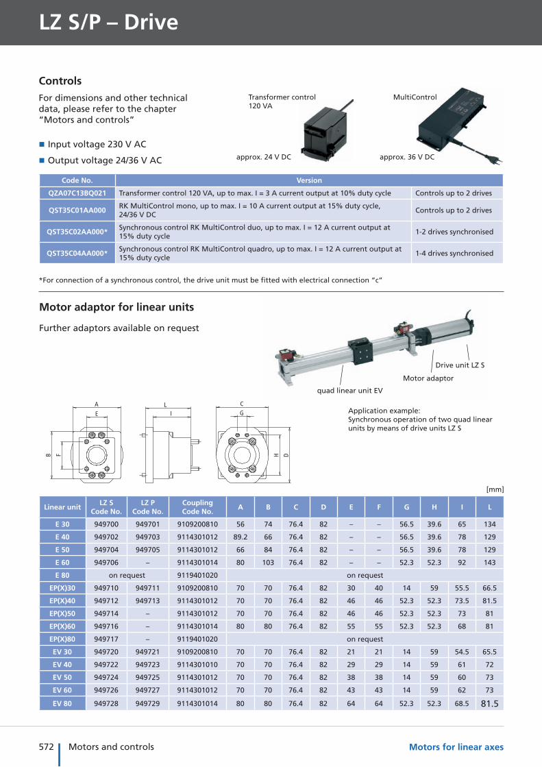
quad linear unit EV
Motor adaptor
Drive unit LZ S
Application example: Synchronous operation of two quad linear units by means of drive units LZ S
E
F
A
B
IL
G
H
C
D
Motor adaptor for linear units
Linear unitLZ S
Code No.LZ P
Code No.CouplingCode No.
A B C D E F G H I L
E 30 949700 949701 9109200810 56 74 76.4 82 – – 56.5 39.6 65 134
E 40 949702 949703 9114301012 89.2 66 76.4 82 – – 56.5 39.6 78 129
E 50 949704 949705 9114301012 66 84 76.4 82 – – 56.5 39.6 78 129
E 60 949706 – 9114301014 80 103 76.4 82 – – 52.3 52.3 92 143
E 80 on request 9119401020 on request
EP(X)30 949710 949711 9109200810 70 70 76.4 82 30 40 14 59 55.5 66.5
EP(X)40 949712 949713 9114301012 70 70 76.4 82 46 46 52.3 52.3 73.5 81.5
EP(X)50 949714 – 9114301012 70 70 76.4 82 46 46 52.3 52.3 73 81
EP(X)60 949716 – 9114301014 80 80 76.4 82 55 55 52.3 52.3 68 81
EP(X)80 949717 – 9119401020 on request
EV 30 949720 949721 9109200810 70 70 76.4 82 21 21 14 59 54.5 65.5
EV 40 949722 949723 9114301010 70 70 76.4 82 29 29 14 59 61 72
EV 50 949724 949725 9114301012 70 70 76.4 82 38 38 14 59 60 73
EV 60 949726 949727 9114301012 70 70 76.4 82 43 43 14 59 62 73
EV 80 949728 949729 9114301014 80 80 76.4 82 64 64 52.3 52.3 68.5 81.5
Further adaptors available on request
[mm]
573Motors and controls
Mo
ve-T
ecPl
ace-
Tec
Co
ntr
ol-
Tec
Intr
od
uct
ion
Sele
ctio
n a
idA
pp
end
ixM
od
ule
sM
oto
rs/
Co
ntr
ols
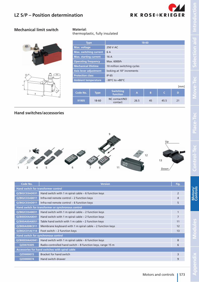
Hand switches/accessories
Code No. Version Fig.
Hand switch for transformer control
QZB02C03AD031 Hand switch with 1 m spiral cable – 6 function keys 2
QZB02C03AB011 Infra-red remote control – 2 function keys 4
QZB02C03AD011 Infra-red remote control – 6 function keys 5
Hand switch for transformer or synchronous control
QZB02C03AB031 Hand switch with 1 m spiral cable – 2 function keys 1
QZB00D04AB041 Hand switch with 1 m spiral cable – 2 function keys 7
QZB00A00AB051 Table hand switch with 1 m cable – 2 function keys 11
QZB00A00BC011 Membrane keyboard with 1 m spiral cable – 2 function keys 12
QZB02C01AE114 Foot switch – 2 function keys 13
Hand switch for synchronous control
QZB00D04AD041 Hand switch with 1 m spiral cable – 6 function keys 8
QZD070305 Radio-controlled hand switch – 8 function keys, range 15 m 6
Accessories for hand switches with spiral cable
QZD000072 Bracket for hand switch 3
QZD000074 Hand switch drawer 9
2 4 5 6 Down
Up
13
87
9
3
1
12
11
Mechanical limit switch Material: thermoplastic, fully insulated
Type 18-60
Max. voltage 250 V AC
Max. switching current 6 A
Max. starting current 16 A
Operating frequency Max. 6000/h
Mechanical lifetime 10 million switching cycles
Axis lever adjustment locking at 10° increments
Protection class IP 65
Ambient temperature -30°C to +80°C
Code No. TypeSwitching function
A B C D
91905 18-60NC contact/NO
contact26.5 45 45.5 21
[mm]
LZ S/P – Position determination
574 Motors and controls Motors for linear axes
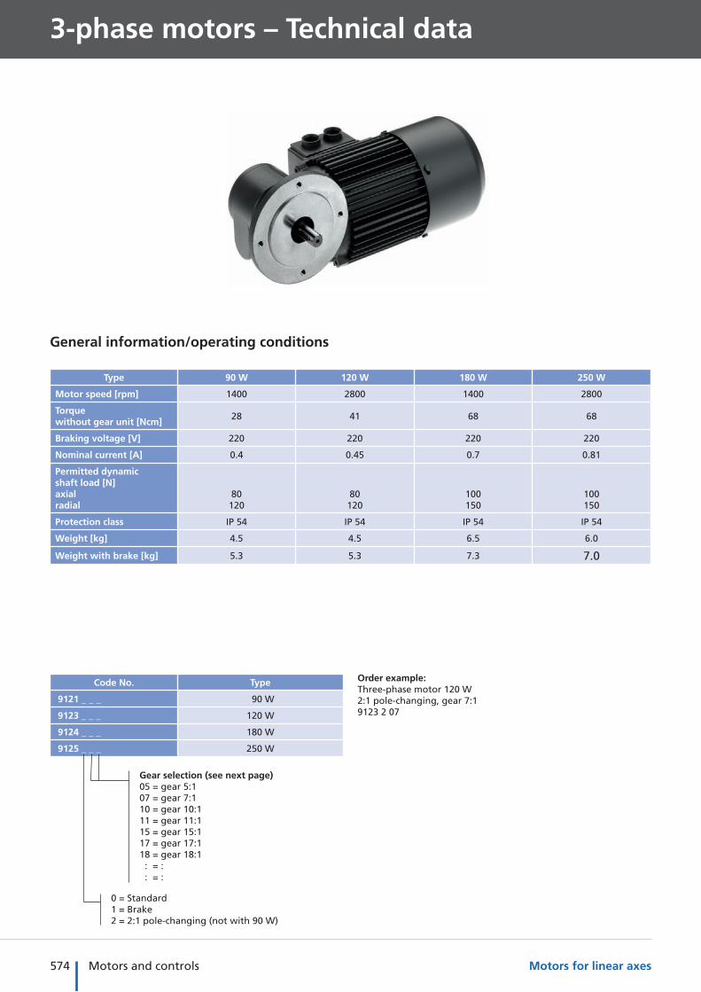
3-phase motors – Technical data
General information/operating conditions
Type 90 W 120 W 180 W 250 W
Motor speed [rpm] 1400 2800 1400 2800
Torque without gear unit [Ncm]
28 41 68 68
Braking voltage [V] 220 220 220 220
Nominal current [A] 0.4 0.45 0.7 0.81
Permitted dynamic shaft load [N]axialradial
80120
80120
100150
100150
Protection class IP 54 IP 54 IP 54 IP 54
Weight [kg] 4.5 4.5 6.5 6.0
Weight with brake [kg] 5.3 5.3 7.3 7.0
Code No. Type
9121 _ _ _ 90 W
9123 _ _ _ 120 W
9124 _ _ _ 180 W
9125 _ _ _ 250 W
Gear selection (see next page)05 = gear 5:107 = gear 7:110 = gear 10:111 = gear 11:115 = gear 15:117 = gear 17:118 = gear 18:1 : = : : = :
0 = Standard1 = Brake2 = 2:1 pole-changing (not with 90 W)
Order example:Three-phase motor 120 W2:1 pole-changing, gear 7:19123 2 07
575Motors and controls
Mo
ve-T
ecPl
ace-
Tec
Co
ntr
ol-
Tec
Intr
od
uct
ion
Sele
ctio
n a
idA
pp
end
ixM
od
ule
sM
oto
rs/
Co
ntr
ols
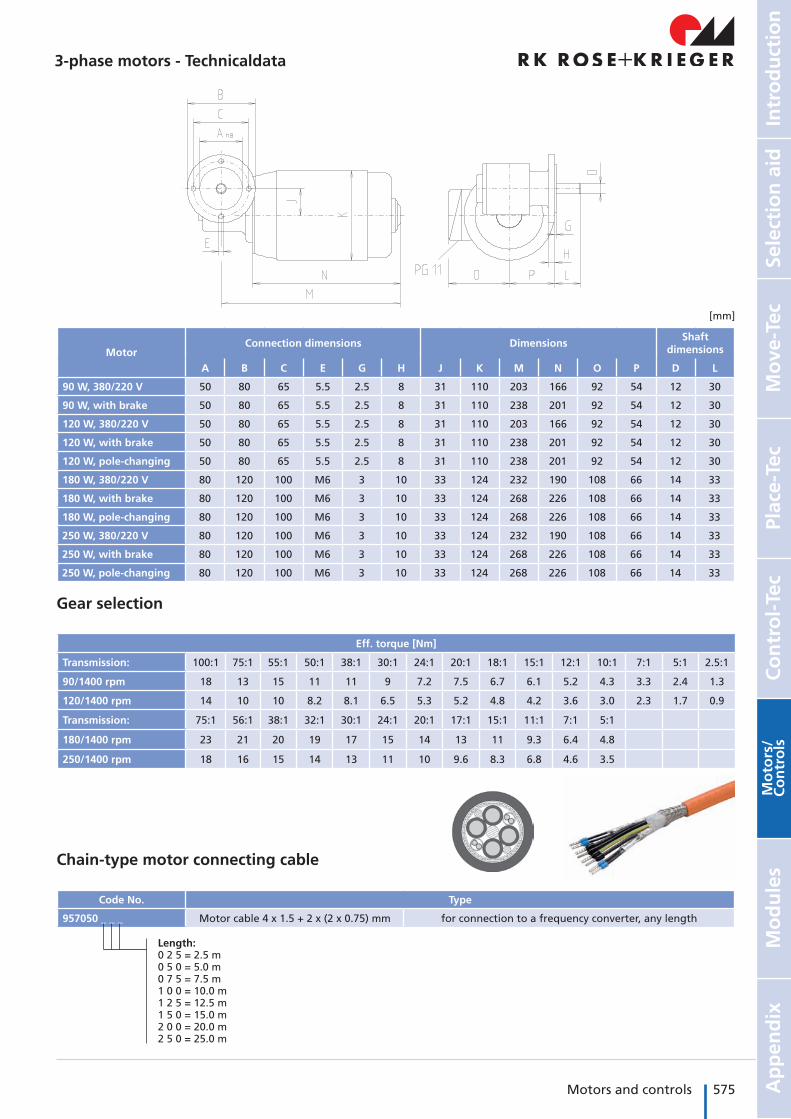
3-phase motors - Technicaldata
MotorConnection dimensions Dimensions
Shaft dimensions
A B C E G H J K M N O P D L
90 W, 380/220 V 50 80 65 5.5 2.5 8 31 110 203 166 92 54 12 30
90 W, with brake 50 80 65 5.5 2.5 8 31 110 238 201 92 54 12 30
120 W, 380/220 V 50 80 65 5.5 2.5 8 31 110 203 166 92 54 12 30
120 W, with brake 50 80 65 5.5 2.5 8 31 110 238 201 92 54 12 30
120 W, pole-changing 50 80 65 5.5 2.5 8 31 110 238 201 92 54 12 30
180 W, 380/220 V 80 120 100 M6 3 10 33 124 232 190 108 66 14 33
180 W, with brake 80 120 100 M6 3 10 33 124 268 226 108 66 14 33
180 W, pole-changing 80 120 100 M6 3 10 33 124 268 226 108 66 14 33
250 W, 380/220 V 80 120 100 M6 3 10 33 124 232 190 108 66 14 33
250 W, with brake 80 120 100 M6 3 10 33 124 268 226 108 66 14 33
250 W, pole-changing 80 120 100 M6 3 10 33 124 268 226 108 66 14 33
Gear selection
Eff. torque [Nm]
Transmission: 100:1 75:1 55:1 50:1 38:1 30:1 24:1 20:1 18:1 15:1 12:1 10:1 7:1 5:1 2.5:1
90/1400 rpm 18 13 15 11 11 9 7.2 7.5 6.7 6.1 5.2 4.3 3.3 2.4 1.3
120/1400 rpm 14 10 10 8.2 8.1 6.5 5.3 5.2 4.8 4.2 3.6 3.0 2.3 1.7 0.9
Transmission: 75:1 56:1 38:1 32:1 30:1 24:1 20:1 17:1 15:1 11:1 7:1 5:1
180/1400 rpm 23 21 20 19 17 15 14 13 11 9.3 6.4 4.8
250/1400 rpm 18 16 15 14 13 11 10 9.6 8.3 6.8 4.6 3.5
Chain-type motor connecting cable
Code No. Type
957050 _ _ _ Motor cable 4 x 1.5 + 2 x (2 x 0.75) mm for connection to a frequency converter, any length
Length:0 2 5 = 2.5 m0 5 0 = 5.0 m0 7 5 = 7.5 m1 0 0 = 10.0 m1 2 5 = 12.5 m1 5 0 = 15.0 m2 0 0 = 20.0 m2 5 0 = 25.0 m
[mm]
576 Motors and controls Motors for linear axes
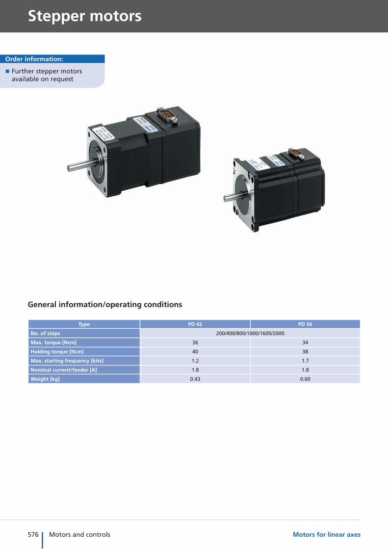
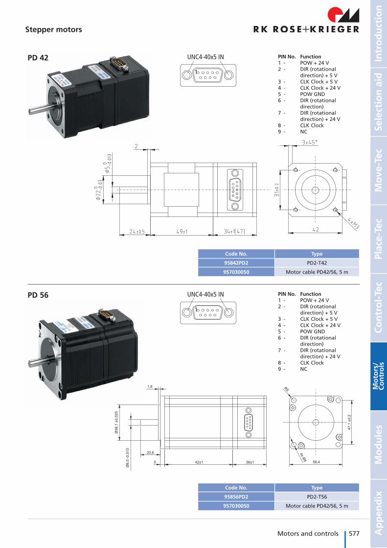
Stepper motors
General information/operating conditions
Type PD 42 PD 56
No. of steps 200/400/800/1000/1600/2000
Max. torque [Ncm] 36 34
Holding torque [Ncm] 40 38
Max. starting frequency [kHz] 1.2 1.7
Nominal current/feeder [A] 1.8 1.8
Weight [kg] 0.43 0.60
� Further stepper motors available on request
Order information:
577Motors and controls
Mo
ve-T
ecPl
ace-
Tec
Co
ntr
ol-
Tec
Intr
od
uct
ion
Sele
ctio
n a
idA
pp
end
ixM
od
ule
sM
oto
rs/
Co
ntr
ols
Stepper motors
PD 42
PD 56
1
UNC4-40x5 IN
1
UNC4-40x5 IN
PIN No. Function1 - POW + 24 V2 - DIR (rotational direction) + 5 V3 - CLK Clock + 5 V4 - CLK Clock + 24 V5 - POW GND6 - DIR (rotational direction)7 - DIR (rotational direction) + 24 V8 - CLK Clock9 - NC
PIN No. Function1 - POW + 24 V2 - DIR (rotational direction) + 5 V3 - CLK Clock + 5 V4 - CLK Clock + 24 V5 - POW GND6 - DIR (rotational direction)7 - DIR (rotational direction) + 24 V8 - CLK Clock9 - NC
Code No. Type
95842PD2 PD2-T42
957030050 Motor cable PD42/56, 5 m
Code No. Type
95856PD2 PD2-T56
957030050 Motor cable PD42/56, 5 m
578 Motors and controls Motors for linear axes
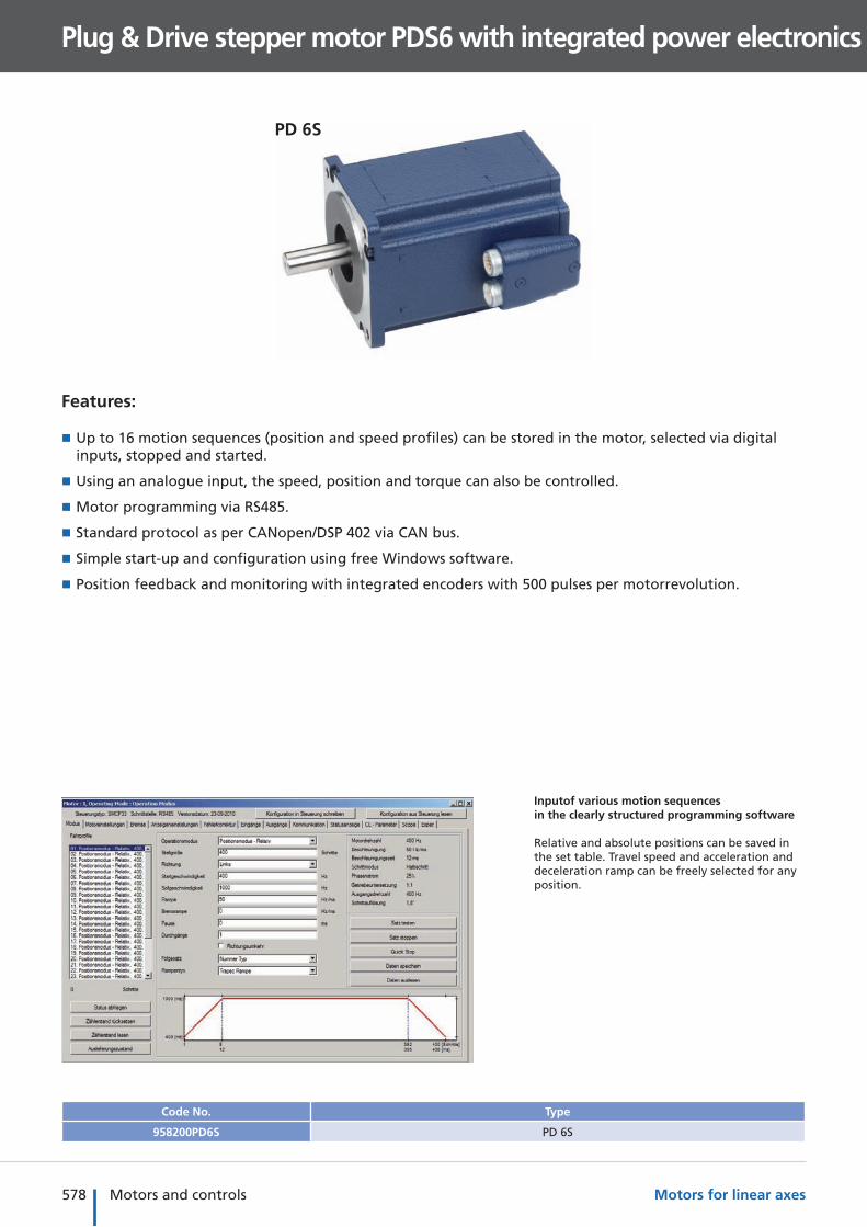
Plug & Drive stepper motor PDS6 with integrated power electronics
PD 6S
Code No. Type
958200PD6S PD 6S
Inputof various motion sequences in the clearly structured programming software
Relative and absolute positions can be saved in the set table. Travel speed and acceleration and deceleration ramp can be freely selected for any position.
Features:
� Up to 16 motion sequences (position and speed profiles) can be stored in the motor, selected via digital inputs, stopped and started.
� Using an analogue input, the speed, position and torque can also be controlled.
� Motor programming via RS485.
� Standard protocol as per CANopen/DSP 402 via CAN bus.
� Simple start-up and configuration using free Windows software.
� Position feedback and monitoring with integrated encoders with 500 pulses per motorrevolution.
579Motors and controls
Mo
ve-T
ecPl
ace-
Tec
Co
ntr
ol-
Tec
Intr
od
uct
ion
Sele
ctio
n a
idA
pp
end
ixM
od
ule
sM
oto
rs/
Co
ntr
ols
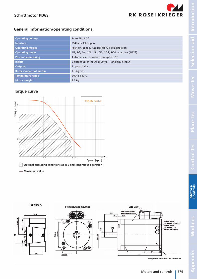
Plug & Drive stepper motor PDS6 with integrated power electronicsSchrittmotor PD6S
General information/operating conditions
Operating voltage 24 to 48V / DC
Interface: RS485 or CANopen
Operating modes Position, speed, flag position, clock direction
Operating mode 1/1, 1/2, 1/4, 1/5, 1/8, 1/10, 1/32, 1/64, adaptive (1/128)
Position monitoring Automatic error correction up to 0.9°
Inputs 6 optocoupler inputs (5-24V) / 1 analogue input
Outputs 3 open drains
Rotor moment of inertia 1.9 kg cm²
Temperature range 0°C to +40°C
Motor weight 3.4 kg
Speed [rpm]
Torq
ue
[Nm
]
Optimal operating conditions at 48V and continuous operation
Maximum value
Torque curve
Integrated encoder and controller
580 Motors and controls Motors for linear axes
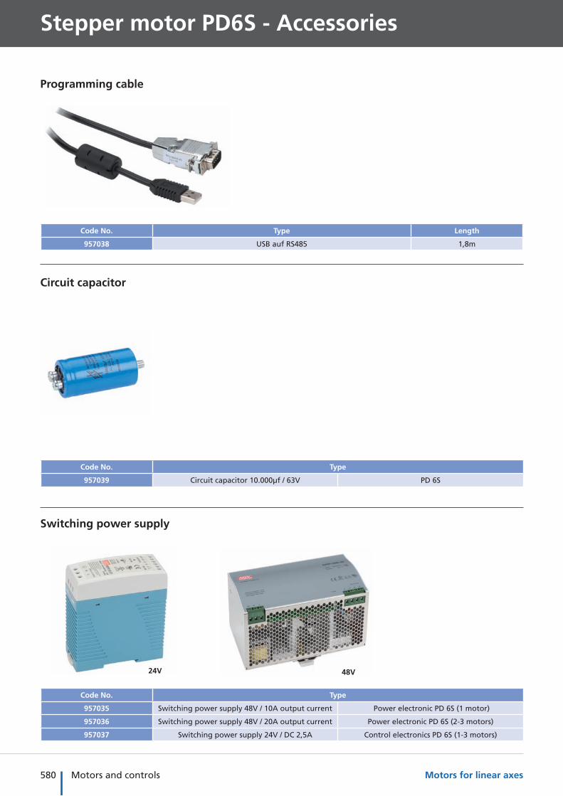
Stepper motor PD6S - Accessories
Circuit capacitor
Code No. Type
957039 Circuit capacitor 10.000µf / 63V PD 6S
Switching power supply
Code No. Type
957035 Switching power supply 48V / 10A output current Power electronic PD 6S (1 motor)
957036 Switching power supply 48V / 20A output current Power electronic PD 6S (2-3 motors)
957037 Switching power supply 24V / DC 2,5A Control electronics PD 6S (1-3 motors)
Programming cable
Code No. Type Length
957038 USB auf RS485 1,8m
24V 48V
581Motors and controls
Mo
ve-T
ecPl
ace-
Tec
Co
ntr
ol-
Tec
Intr
od
uct
ion
Sele
ctio
n a
idA
pp
end
ixM
od
ule
sM
oto
rs/
Co
ntr
ols
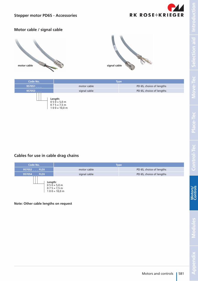
Stepper motor PD6S - Accessories
Motor cable / signal cable
Code No. Type
957051 _ _ _ motor cable PD 6S, choice of lengths
957053 _ _ _ signal cable PD 6S, choice of lengths
Cables for use in cable drag chains
Code No. Type
957052 _ _ _ FLEX motor cable PD 6S, choice of lengths
957054 _ _ _ FLEX signal cable PD 6S, choice of lengths
Length:0 5 0 = 5,0 m0 7 5 = 7,5 m1 0 0 = 10,0 m
Length:0 5 0 = 5,0 m0 7 5 = 7,5 m1 0 0 = 10,0 m
motor cable signal cable
Note: Other cable lengths on request
582 Motors and controls Motors for linear axes
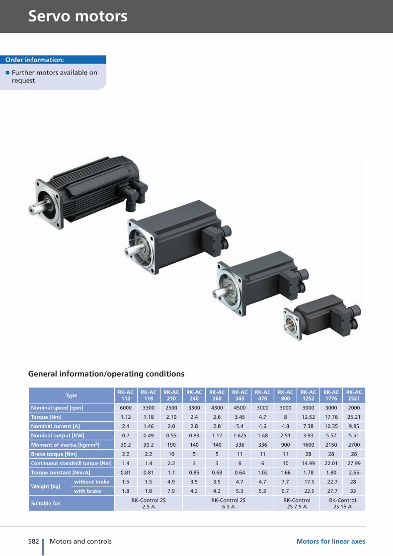
Servo motors
General information/operating conditions
TypeRK-AC
112RK-AC
118RK-AC
210RK-AC
240RK-AC
260RK-AC
345RK-AC
470RK-AC
800RK-AC 1252
RK-AC 1776
RK-AC 2521
Nominal speed [rpm] 6000 3300 2500 3300 4300 4500 3000 3000 3000 3000 2000
Torque [Nm] 1.12 1.18 2.10 2.4 2.6 3.45 4.7 8 12.52 17.76 25.21
Nominal current [A] 2.4 1.46 2.0 2.8 2.8 5.4 4.6 4.8 7.38 10.35 9.95
Nominal output [KW] 0.7 0.49 0.55 0.83 1.17 1.625 1.48 2.51 3.93 5.57 5.51
Moment of inertia [kgmm2] 30.2 30.2 190 140 140 336 336 900 1600 2150 2700
Brake torque [Nm] 2.2 2.2 10 5 5 11 11 11 28 28 28
Continuous standstill torque [Nm] 1.4 1.4 2.2 3 3 6 6 10 14.99 22.01 27.99
Torque constant [Nm/A] 0.81 0.81 1.1 0.85 0.68 0.64 1.02 1.66 1.78 1.80 2.65
Weight [kg] without brake 1.5 1.5 4.9 3.5 3.5 4.7 4.7 7.7 17.5 22.7 28
with brake 1.8 1.8 7.9 4.2 4.2 5.3 5.3 9.7 22.5 27.7 33
Suitable for:RK-Control 2S
2.5 ARK-Control 2S
6.3 ARK-Control
2S 7.5 ARK-Control
2S 15 A
Order information:
� Further motors available on request
583Motors and controls
Mo
ve-T
ecPl
ace-
Tec
Co
ntr
ol-
Tec
Intr
od
uct
ion
Sele
ctio
n a
idA
pp
end
ixM
od
ule
sM
oto
rs/
Co
ntr
ols
Servo motors
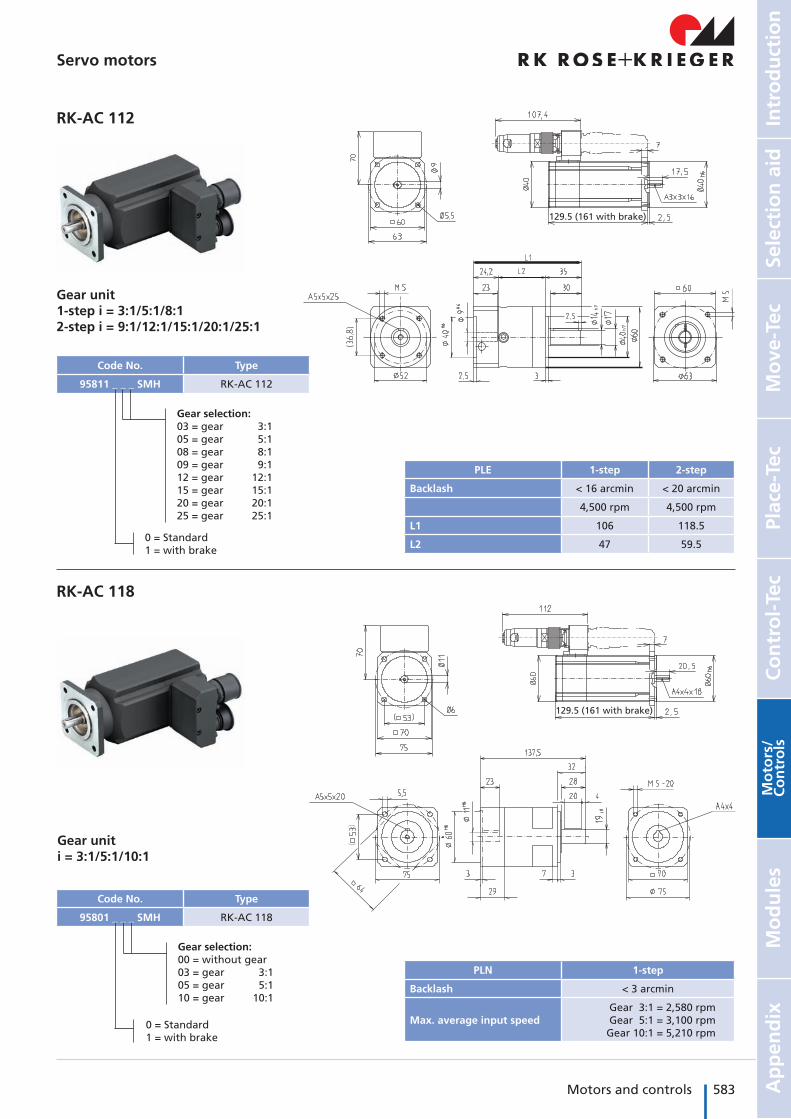
RK-AC 112
RK-AC 118
Gear unit1-step i = 3:1/5:1/8:12-step i = 9:1/12:1/15:1/20:1/25:1
Gear uniti = 3:1/5:1/10:1
129.5 (161 with brake)
129.5 (161 with brake)
PLE 1-step 2-step
Backlash < 16 arcmin < 20 arcmin
4,500 rpm 4,500 rpm
L1 106 118.5
L2 47 59.5
PLN 1-step
Backlash < 3 arcmin
Max. average input speedGear 3:1 = 2,580 rpmGear 5:1 = 3,100 rpmGear 10:1 = 5,210 rpm
Code No. Type
95811 _ _ _ SMH RK-AC 112
Code No. Type
95801 _ _ _ SMH RK-AC 118
Gear selection:03 = gear 3:105 = gear 5:108 = gear 8:109 = gear 9:112 = gear 12:115 = gear 15:120 = gear 20:125 = gear 25:1
0 = Standard1 = with brake
Gear selection:00 = without gear03 = gear 3:105 = gear 5:110 = gear 10:1
0 = Standard1 = with brake
584 Motors and controls Motors for linear axes
Servo motors
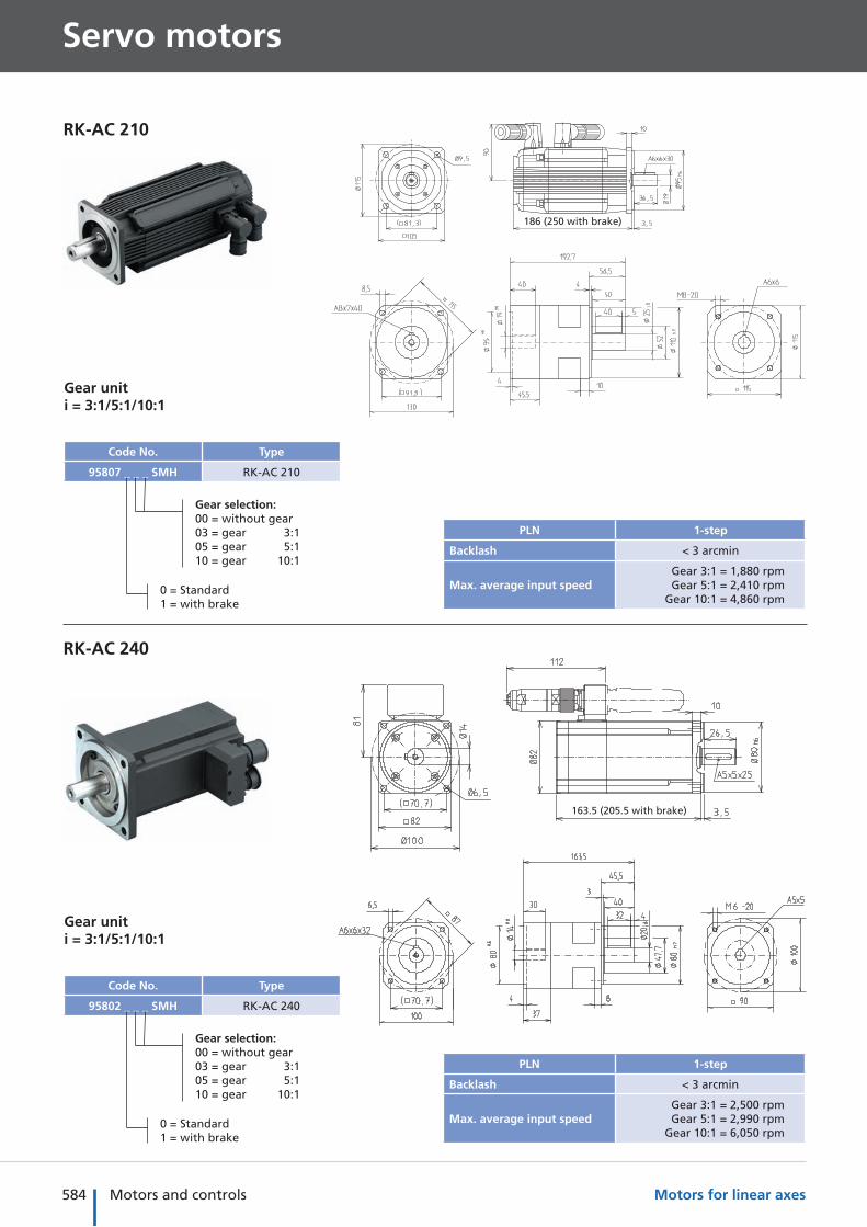
RK-AC 210
RK-AC 240
163.5 (205.5 with brake)
186 (250 with brake)
PLN 1-step
Backlash < 3 arcmin
Max. average input speedGear 3:1 = 1,880 rpmGear 5:1 = 2,410 rpm
Gear 10:1 = 4,860 rpm
PLN 1-step
Backlash < 3 arcmin
Max. average input speedGear 3:1 = 2,500 rpmGear 5:1 = 2,990 rpm
Gear 10:1 = 6,050 rpm
Gear uniti = 3:1/5:1/10:1
Code No. Type
95802 _ _ _ SMH RK-AC 240
Gear selection:00 = without gear03 = gear 3:105 = gear 5:110 = gear 10:1
0 = Standard1 = with brake
Gear uniti = 3:1/5:1/10:1
Code No. Type
95807 _ _ _ SMH RK-AC 210
Gear selection:00 = without gear03 = gear 3:105 = gear 5:110 = gear 10:1
0 = Standard1 = with brake
585Motors and controls
Mo
ve-T
ecPl
ace-
Tec
Co
ntr
ol-
Tec
Intr
od
uct
ion
Sele
ctio
n a
idA
pp
end
ixM
od
ule
sM
oto
rs/
Co
ntr
ols
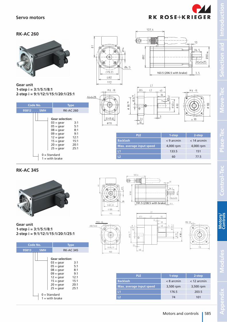
RK-AC 260
RK-AC 345
Gear unit1-step i = 3:1/5:1/8:12-step i = 9:1/12:1/15:1/20:1/25:1
191.5 (238.5 with brake)
163.5 (206.5 with brake)
PLE 1-step 2-step
Backlash < 9 arcmin < 14 arcmin
Max. average input speed 4,000 rpm 4,000 rpm
L1 133.5 151
L2 60 77.5
Code No. Type
95812 _ _ _ SMH RK-AC 260
Gear selection:03 = gear 3:105 = gear 5:108 = gear 8:109 = gear 9:112 = gear 12:115 = gear 15:120 = gear 20:125 = gear 25:1
0 = Standard1 = with brake
Gear unit1-step i = 3:1/5:1/8:12-step i = 9:1/12:1/15:1/20:1/25:1
Code No. Type
95813 _ _ _ SMH RK-AC 345
Gear selection:03 = gear 3:105 = gear 5:108 = gear 8:109 = gear 9:112 = gear 12:115 = gear 15:120 = gear 20:125 = gear 25:1
0 = Standard1 = with brake
PLE 1-step 2-step
Backlash < 8 arcmin < 12 arcmin
Max. average input speed 3,500 rpm 3,500 rpm
L1 176.5 203.5
L2 74 101
Servo motors
586 Motors and controls Motors for linear axes
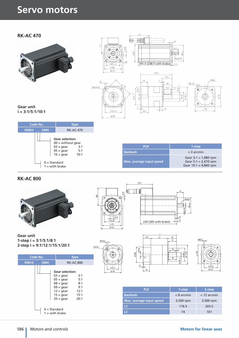
220 (265 with brake)
RK-AC 470
191.5 (238.5 with brake)
PLN 1-step
Backlash < 3 arcmin
Max. average input speedGear 3:1 = 1,880 rpmGear 5:1 = 2,410 rpm
Gear 10:1 = 4,860 rpm
Gear uniti = 3:1/5:1/10:1
Code No. Type
95803 _ _ _ SMH RK-AC 470
Gear selection:00 = without gear03 = gear 3:105 = gear 5:110 = gear 10:1
0 = Standard1 = with brake
RK-AC 800
Gear unit1-step i = 3:1/5:1/8:12-step i = 9:1/12:1/15:1/20:1
Code No. Type
95814 _ _ _ SMH RK-AC 800
Gear selection:03 = gear 3:105 = gear 5:108 = gear 8:109 = gear 9:112 = gear 12:115 = gear 15:120 = gear 20:1
0 = Standard1 = with brake
PLE 1-step 2-step
Backlash < 8 arcmin < 12 arcmin
Max. average input speed 3,500 rpm 3,500 rpm
L1 176.5 203.5
L2 74 101
Servo motors
587Motors and controls
Mo
ve-T
ecPl
ace-
Tec
Co
ntr
ol-
Tec
Intr
od
uct
ion
Sele
ctio
n a
idA
pp
end
ixM
od
ule
sM
oto
rs/
Co
ntr
ols
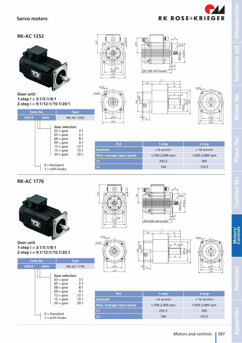
RK-AC 1252
Gear unit1-step i = 3:1/5:1/8:12-step i = 9:1/12:1/15:1/20:1
A8x7x40
A12x8x65
12
5
145116,67
165
11
,5
13
0h
6
3,5
10
3
M8
x1
9
50
M12x20
L2
40
h7
65
82
8764,5
13
0h
7
16
0
140
M10x25
165
116,67
24
13
0
450
145
102,53
24 12
L1
80
8
292 (366 with brake)
PLE 1-step 2-step
Backlash < 6 arcmin < 10 arcmin
Max. average input speed 1,700-2,900 rpm 1,950-3,000 rpm
L1 255.5 305
L2 104 153.5
Code No. Type
95815 _ _ _ SMH RK-AC 1252
Gear selection:03 = gear 3:105 = gear 5:108 = gear 8:109 = gear 9:112 = gear 12:115 = gear 15:120 = gear 20:1
0 = Standard1 = with brake
RK-AC 1776
Gear unit1-step i = 3:1/5:1/8:12-step i = 9:1/12:1/15:1/20:1
Code No. Type
95816 _ _ _ SMH RK-AC 1776
Gear selection:03 = gear 3:105 = gear 5:108 = gear 8:109 = gear 9:112 = gear 12:115 = gear 15:120 = gear 20:1
0 = Standard1 = with brake
PLE 1-step 2-step
Backlash < 6 arcmin < 10 arcmin
Max. average input speed 1,700-2,900 rpm 1,950-3,000 rpm
L1 255.5 305
L2 104 153.5
354 (428 with brake)
Servo motors
588 Motors and controls Motors for linear axes
Servo motors
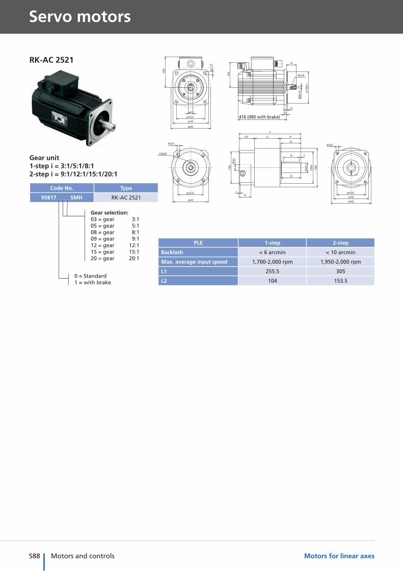
RK-AC 2521
Gear unit1-step i = 3:1/5:1/8:12-step i = 9:1/12:1/15:1/20:1
Code No. Type
95817 _ _ _ SMH RK-AC 2521
Gear selection:03 = gear 3:105 = gear 5:108 = gear 8:109 = gear 9:112 = gear 12:115 = gear 15:120 = gear 20:1
0 = Standard1 = with brake
PLE 1-step 2-step
Backlash < 6 arcmin < 10 arcmin
Max. average input speed 1,700-2,000 rpm 1,950-2,000 rpm
L1 255.5 305
L2 104 153.5
416 (490 with brake)
589Motors and controls
Mo
ve-T
ecPl
ace-
Tec
Co
ntr
ol-
Tec
Intr
od
uct
ion
Sele
ctio
n a
idA
pp
end
ixM
od
ule
sM
oto
rs/
Co
ntr
ols
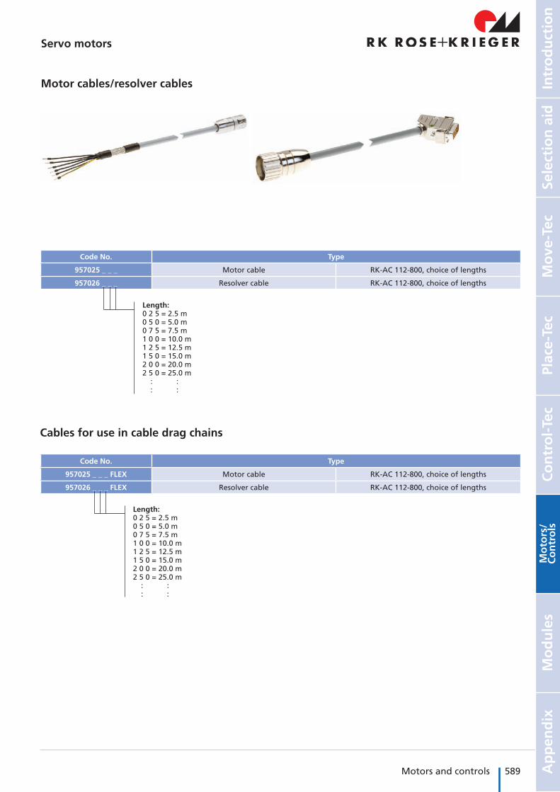
Motor cables/resolver cables
Code No. Type
957025 _ _ _ Motor cable RK-AC 112-800, choice of lengths
957026 _ _ _ Resolver cable RK-AC 112-800, choice of lengths
Cables for use in cable drag chains
Code No. Type
957025 _ _ _ FLEX Motor cable RK-AC 112-800, choice of lengths
957026 _ _ _ FLEX Resolver cable RK-AC 112-800, choice of lengths
Length:0 2 5 = 2.5 m0 5 0 = 5.0 m0 7 5 = 7.5 m1 0 0 = 10.0 m1 2 5 = 12.5 m1 5 0 = 15.0 m2 0 0 = 20.0 m2 5 0 = 25.0 m : : : :
Length:0 2 5 = 2.5 m0 5 0 = 5.0 m0 7 5 = 7.5 m1 0 0 = 10.0 m1 2 5 = 12.5 m1 5 0 = 15.0 m2 0 0 = 20.0 m2 5 0 = 25.0 m : : : :
Servo motors
590 Motors and controls Motors for linear axes
TypeThree-phase motor
90/120 W 180/250 W
EP(X) 30949623 –
911940 0812 –
EP(X) 40949614 94914
911430 1212 911430 1214
EP(X) 50949614 949414
911430 1212 911430 1214
EP(X) 60– 949616
– 911940 1414
EP(X) 80– 949909
– 911940 1420
COPAS 20949623 –
911940 0812 –
COPAS 30949614 949048
911430 1012 911430 1014
COPAS 40949614 949048
911430 1212 911430 1214
EV 30949603 –
910920 0812 –
EV 4094937 94916
911430 1012 911430 1014
EV 50949605 94935
911940 1212 911430 1214
EV 6094976 949077
911940 1212 911430 1214
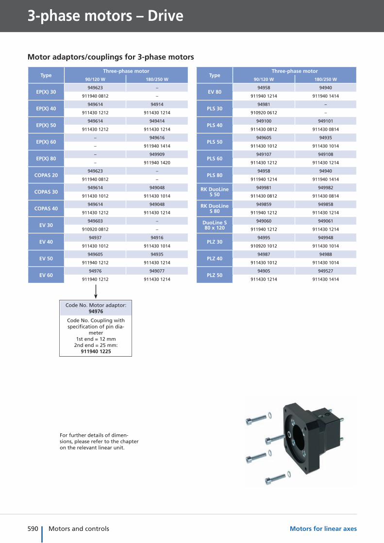
3-phase motors – Drive
Code No. Motor adaptor: 94976
Code No. Coupling with specification of pin dia-
meter1st end = 12 mm
2nd end = 25 mm: 911940 1225
TypeThree-phase motor
90/120 W 180/250 W
EV 8094958 94940
911940 1214 911940 1414
PLS 3094981 –
910920 0612 –
PLS 40949100 949101
911430 0812 911430 0814
PLS 50949605 94935
911430 1012 911430 1014
PLS 60949107 949108
911430 1212 911430 1214
PLS 8094958 94940
911940 1214 911940 1414
RK DuoLine S 50
949981 949982
911430 0812 911430 0814
RK DuoLine S 80
949859 949858
911940 1212 911430 1214
DuoLine S 80 x 120
949060 949061
911940 1212 911430 1214
PLZ 3094995 949948
910920 1012 911430 1014
PLZ 4094987 94988
911430 1012 911430 1014
PLZ 5094905 949527
911430 1214 911430 1414
For further details of dimen-sions, please refer to the chapter on the relevant linear unit.
Motor adaptors/couplings for 3-phase motors
591Motors and controls
Mo
ve-T
ecPl
ace-
Tec
Co
ntr
ol-
Tec
Intr
od
uct
ion
Sele
ctio
n a
idA
pp
end
ixM
od
ule
sM
oto
rs/
Co
ntr
ols
TypeThree-phase motor
90/120 W 180/250 W
PLZ 6094956 94950
911940 1220 911940 1420
PLZ 80949329 949114
912855 1225 912855 1425
PLZ-i 30949504 –
910920 0612 –
PLZ-i 40949516 949517
911430 0812 911430 0814
PLZ-i 50949526 949527
911940 1012 911940 1014
PLZ-i 60949547 949548
911940 1212 911430 1214
PLZ-i 80949547 949567
911940 1214 911430 1414
SQZ 3094995 –
910920 1012 –
SQZ 40, 40 x 80
94987 94988
911430 1012 911430 1014
SQZ 60, 60 x 120
949029 949030
911940 1215 911940 1415
SQZ80 x 160
94956 94950
911940 1220 911940 1420
SQZ 80949695 949697
912855 1225 912855 1425
TypeThree-phase motor
90/120 W 180/250 W
SQ MT 30949913 949949
910920 1012 911430 1014
SQ MT 40, 40 x 80
949920 949921
911430 1012 911430 1014
SQ MT 50, 50 x 100
949928 949929
911430 1214 911430 1414
SQ MT 60, 60 x 120
949938 949939
911940 1220 911940 1420
SQ MT 80, 80 x 160
949944 949945
912855 1225 912855 2025
LMZ949039 949114
912855 1225 912855 1425
DuoLine Z 50
949974 949975
911940 1012 911940 1014
DuoLine Z 80
949958 949959
911940 1220 911940 1420
DuoLine Z 120 x 80
949043 949808
912855 1225 912855 1425
MultiLine 949968 949969
912855 1230 912855 1430
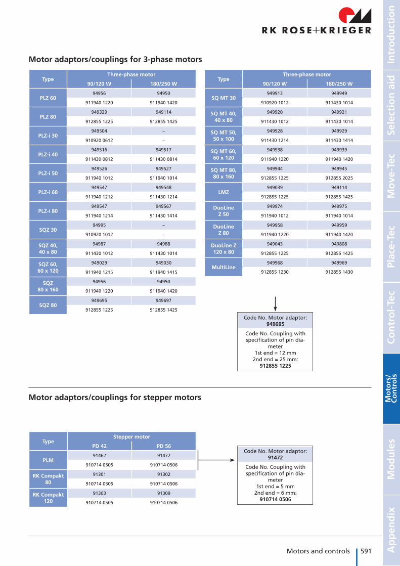
Code No. Motor adaptor: 949695
Code No. Coupling with specification of pin dia-
meter1st end = 12 mm
2nd end = 25 mm: 912855 1225
TypeStepper motor
PD 42 PD 56
PLM91462 91472
910714 0505 910714 0506
RK Compakt 80
91301 91302
910714 0505 910714 0506
RK Compakt 120
91303 91309
910714 0505 910714 0506
Motor adaptors/couplings for stepper motors
Motor adaptors/couplings for 3-phase motors
Code No. Motor adaptor: 91472
Code No. Coupling with specification of pin dia-
meter1st end = 5 mm
2nd end = 6 mm: 910714 0506
592 Motors and controls Motors for linear axes
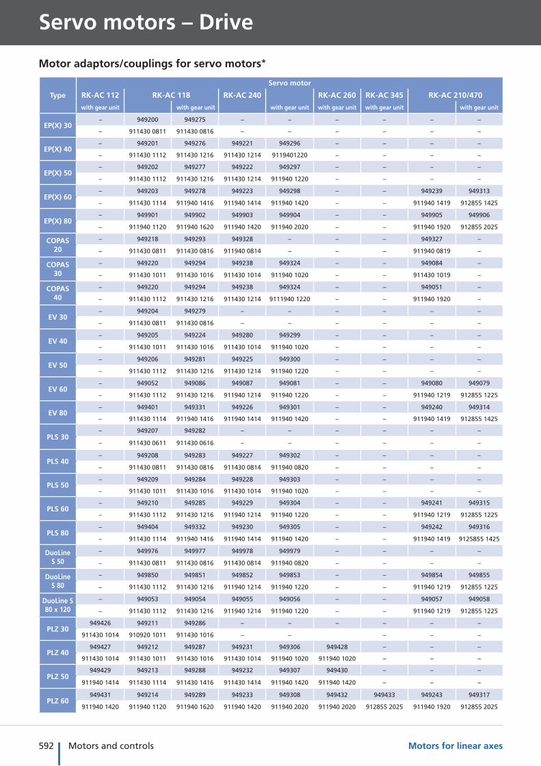
Servo motors – Drive
Type
Servo motor
RK-AC 112 RK-AC 118 RK-AC 240 RK-AC 260 RK-AC 345 RK-AC 210/470
with gear unit with gear unit with gear unit with gear unit with gear unit with gear unit
EP(X) 30– 949200 949275 – – – – – –
– 911430 0811 911430 0816 – – – – – –
EP(X) 40– 949201 949276 949221 949296 – – – –
– 911430 1112 911430 1216 911430 1214 9119401220 – – – –
EP(X) 50– 949202 949277 949222 949297 – – – –
– 911430 1112 911430 1216 911430 1214 911940 1220 – – – –
EP(X) 60– 949203 949278 949223 949298 – – 949239 949313
– 911430 1114 911940 1416 911940 1414 911940 1420 – – 911940 1419 912855 1425
EP(X) 80– 949901 949902 949903 949904 – – 949905 949906
– 911940 1120 911940 1620 911940 1420 911940 2020 – – 911940 1920 912855 2025
COPAS 20
– 949218 949293 949328 – – – 949327 –
– 911430 0811 911430 0816 911940 0814 – – – 911940 0819 –
COPAS 30
– 949220 949294 949238 949324 – – 949084 –
– 911430 1011 911430 1016 911430 1014 911940 1020 – – 911430 1019 –
COPAS 40
– 949220 949294 949238 949324 – – 949051 –
– 911430 1112 911430 1216 911430 1214 9111940 1220 – – 911940 1920 –
EV 30– 949204 949279 – – – – – –
– 911430 0811 911430 0816 – – – – – –
EV 40– 949205 949224 949280 949299 – – – –
– 911430 1011 911430 1016 911430 1014 911940 1020 – – – –
EV 50– 949206 949281 949225 949300 – – – –
– 911430 1112 911430 1216 911430 1214 911940 1220 – – – –
EV 60– 949052 949086 949087 949081 – – 949080 949079
– 911430 1112 911430 1216 911940 1214 911940 1220 – – 911940 1219 912855 1225
EV 80– 949401 949331 949226 949301 – – 949240 949314
– 911430 1114 911940 1416 911940 1414 911940 1420 – – 911940 1419 912855 1425
PLS 30– 949207 949282 – – – – – –
– 911430 0611 911430 0616 – – – – – –
PLS 40– 949208 949283 949227 949302 – – – –
– 911430 0811 911430 0816 911430 0814 911940 0820 – – – –
PLS 50– 949209 949284 949228 949303 – – – –
– 911430 1011 911430 1016 911430 1014 911940 1020 – – – –
PLS 60– 949210 949285 949229 949304 – – 949241 949315
– 911430 1112 911430 1216 911940 1214 911940 1220 – – 911940 1219 912855 1225
PLS 80– 949404 949332 949230 949305 – – 949242 949316
– 911430 1114 911940 1416 911940 1414 911940 1420 – – 911940 1419 9125855 1425
DuoLine S 50
– 949976 949977 949978 949979 – – – –
– 911430 0811 911430 0816 911430 0814 911940 0820 – – – –
DuoLine S 80
– 949850 949851 949852 949853 – – 949854 949855
– 911430 1112 911430 1216 911940 1214 911940 1220 – – 911940 1219 912855 1225
DuoLine S 80 x 120
– 949053 949054 949055 949056 – – 949057 949058
– 911430 1112 911430 1216 911940 1214 911940 1220 – – 911940 1219 912855 1225
PLZ 30949426 949211 949286 – – – – – –
911430 1014 910920 1011 911430 1016 – – – – –
PLZ 40949427 949212 949287 949231 949306 949428 – – –
911430 1014 911430 1011 911430 1016 911430 1014 911940 1020 911940 1020 – – –
PLZ 50949429 949213 949288 949232 949307 949430 – – –
911940 1414 911430 1114 911430 1416 911430 1414 911940 1420 911940 1420 – – –
PLZ 60949431 949214 949289 949233 949308 949432 949433 949243 949317
911940 1420 911940 1120 911940 1620 911940 1420 911940 2020 911940 2020 912855 2025 911940 1920 912855 2025
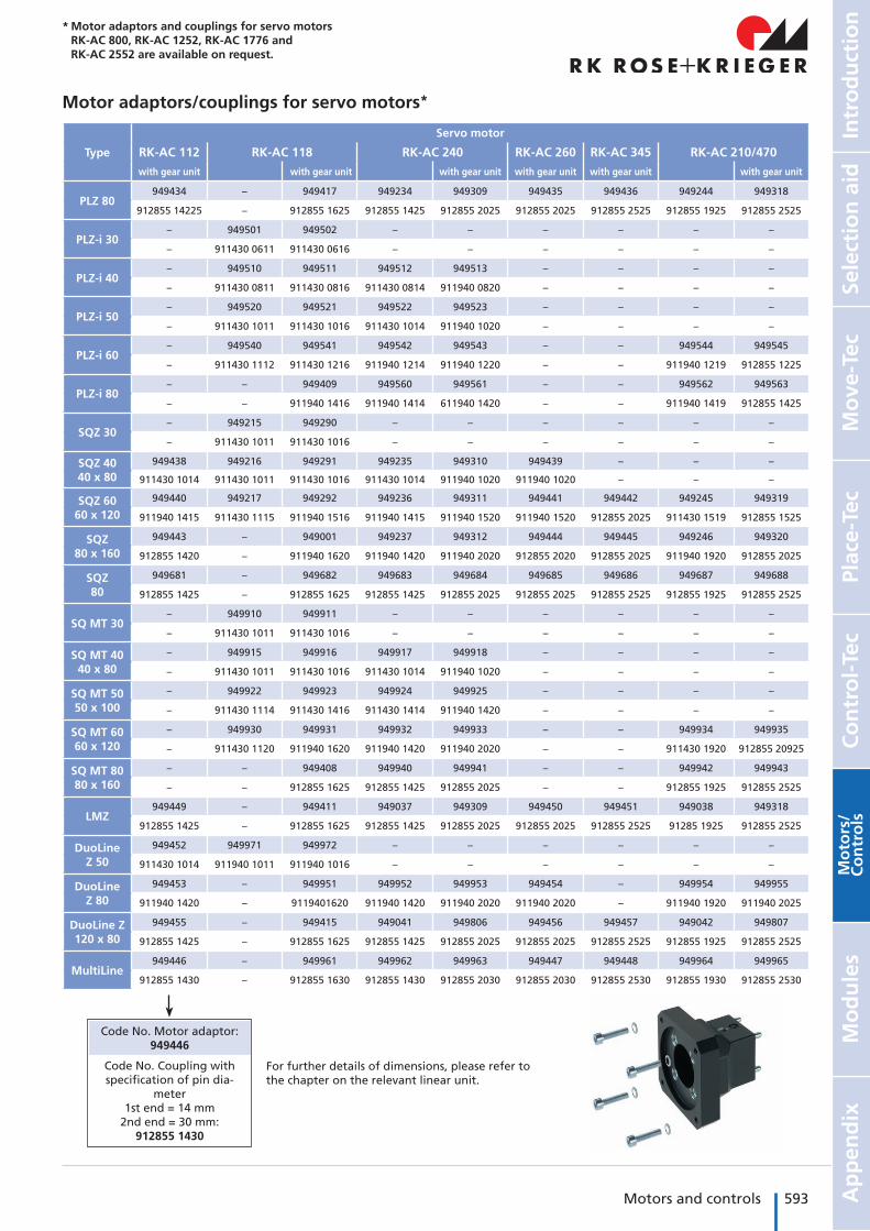
Motor adaptors/couplings for servo motors*
593Motors and controls
Mo
ve-T
ecPl
ace-
Tec
Co
ntr
ol-
Tec
Intr
od
uct
ion
Sele
ctio
n a
idA
pp
end
ixM
od
ule
sM
oto
rs/
Co
ntr
ols
Type
Servo motor
RK-AC 112 RK-AC 118 RK-AC 240 RK-AC 260 RK-AC 345 RK-AC 210/470
with gear unit with gear unit with gear unit with gear unit with gear unit with gear unit
PLZ 80949434 – 949417 949234 949309 949435 949436 949244 949318
912855 14225 – 912855 1625 912855 1425 912855 2025 912855 2025 912855 2525 912855 1925 912855 2525
PLZ-i 30– 949501 949502 – – – – – –
– 911430 0611 911430 0616 – – – – – –
PLZ-i 40– 949510 949511 949512 949513 – – – –
– 911430 0811 911430 0816 911430 0814 911940 0820 – – – –
PLZ-i 50– 949520 949521 949522 949523 – – – –
– 911430 1011 911430 1016 911430 1014 911940 1020 – – – –
PLZ-i 60– 949540 949541 949542 949543 – – 949544 949545
– 911430 1112 911430 1216 911940 1214 911940 1220 – – 911940 1219 912855 1225
PLZ-i 80– – 949409 949560 949561 – – 949562 949563
– – 911940 1416 911940 1414 611940 1420 – – 911940 1419 912855 1425
SQZ 30– 949215 949290 – – – – – –
– 911430 1011 911430 1016 – – – – – –
SQZ 4040 x 80
949438 949216 949291 949235 949310 949439 – – –
911430 1014 911430 1011 911430 1016 911430 1014 911940 1020 911940 1020 – – –
SQZ 6060 x 120
949440 949217 949292 949236 949311 949441 949442 949245 949319
911940 1415 911430 1115 911940 1516 911940 1415 911940 1520 911940 1520 912855 2025 911430 1519 912855 1525
SQZ 80 x 160
949443 – 949001 949237 949312 949444 949445 949246 949320
912855 1420 – 911940 1620 911940 1420 911940 2020 912855 2020 912855 2025 911940 1920 912855 2025
SQZ80
949681 – 949682 949683 949684 949685 949686 949687 949688
912855 1425 – 912855 1625 912855 1425 912855 2025 912855 2025 912855 2525 912855 1925 912855 2525
SQ MT 30– 949910 949911 – – – – – –
– 911430 1011 911430 1016 – – – – – –
SQ MT 40 40 x 80
– 949915 949916 949917 949918 – – – –
– 911430 1011 911430 1016 911430 1014 911940 1020 – – – –
SQ MT 50 50 x 100
– 949922 949923 949924 949925 – – – –
– 911430 1114 911430 1416 911430 1414 911940 1420 – – – –
SQ MT 60 60 x 120
– 949930 949931 949932 949933 – – 949934 949935
– 911430 1120 911940 1620 911940 1420 911940 2020 – – 911430 1920 912855 20925
SQ MT 80 80 x 160
– – 949408 949940 949941 – – 949942 949943
– – 912855 1625 912855 1425 912855 2025 – – 912855 1925 912855 2525
LMZ949449 – 949411 949037 949309 949450 949451 949038 949318
912855 1425 – 912855 1625 912855 1425 912855 2025 912855 2025 912855 2525 91285 1925 912855 2525
DuoLine Z 50
949452 949971 949972 – – – – – –
911430 1014 911940 1011 911940 1016 – – – – – –
DuoLine Z 80
949453 – 949951 949952 949953 949454 – 949954 949955
911940 1420 – 9119401620 911940 1420 911940 2020 911940 2020 – 911940 1920 911940 2025
DuoLine Z 120 x 80
949455 – 949415 949041 949806 949456 949457 949042 949807
912855 1425 – 912855 1625 912855 1425 912855 2025 912855 2025 912855 2525 912855 1925 912855 2525
MultiLine 949446 – 949961 949962 949963 949447 949448 949964 949965
912855 1430 – 912855 1630 912855 1430 912855 2030 912855 2030 912855 2530 912855 1930 912855 2530
For further details of dimensions, please refer to the chapter on the relevant linear unit.
Code No. Motor adaptor: 949446
Code No. Coupling with specification of pin dia-
meter1st end = 14 mm
2nd end = 30 mm: 912855 1430
Motor adaptors/couplings for servo motors*
* Motor adaptors and couplings for servo motors RK-AC 800, RK-AC 1252, RK-AC 1776 and RK-AC 2552 are available on request.