Embed Size (px)
Citation preview
12
Elaboration and Properties of Carbon Fibre Reinforced Copper Matrix Composites
Pierre-Marie Geffroy1, Jean-François Silvain2 and Jean-Marc Heintz2 1CNRS, Science des procédés céramiques et de traitements de surface, Limoges
2CNRS, Institut de la Chimie et de la Matière Condensée de Bordeaux France
1. Introduction
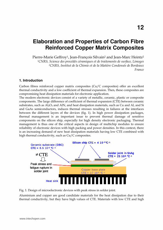
Carbon fibres reinforced copper matrix composites (Cu/C composites) offer an excellent thermal conductivity and a low coefficient of thermal expansion. Then, these composites are compromising heat dissipation materials for electronic application. The modern electronic devices consist of a variety of metallic, ceramic, plastic or composite components. The large difference of coefficient of thermal expansion (CTE) between ceramic substrates, such as Al2O3 and AlN, and heat dissipation materials, such as Cu and Al, and Si and GaAs semiconductors, induces thermal stresses resulting in failures at the interfaces between the different layers of the devices (fig. 1). In high power dissipation packages, thermal management is an important issue to prevent thermal damage of sensitive components on the silicon ship, especially for high density electronic packaging. Thermal management is thus one of the critical aspects in design of multichip modules to ensure reliability of electronic devices with high packing and power densities. In this context, there is an increasing demand of new heat dissipation materials having low CTE combined with high thermal conductivity, such as Cu/C composites.
Silicon chip CTE = 4 10- °C -1
Ceramic subst rate ( DBC)CTE = 6.5 10-6 °C -1
Solder joint in SnAgCTE = 23 10-6 °C -1CTE
Copper base plate CTE = 17 10-6 °C - 1
Silicon chip CTE = 4 10 6 °C -1
CTE = 6.5 10-6 °C -1
Solder joint in SnAgCTE = 23 10-6 °C -1≠
Copper base plate CTE = 17 10-6 °C - 1
Heat sink
Peak stress and
fatigue rupture in
solder joint
Fig. 1. Design of microelectronic devices with peak stress in solder joint.
Aluminium and copper are good candidate materials for the heat dissipation due to their thermal conductivity, but they have high values of CTE. Materials with low CTE and high
www.intechopen.com
Advances in Composites Materials - Ecodesign and Analysis
272
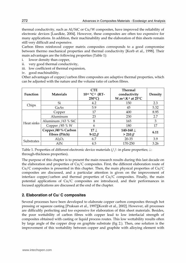
thermal conductivity, such as Al/SiC or Cu/W composites, have improved the reliability of electronic devices [Luedkte, 2004]. However, these composites are often too expensive for many applications. In addition, their machinability and the elaboration of thin sheets remain still very difficult and expensive. Carbon fibres reinforced copper matrix composites corresponds to a good compromise between thermo mechanical properties and thermal conductivity [Korb et al., 1998]. Their main advantages are the following properties (Table 1): i. lower density than copper, ii. very good thermal conductivity, iii. low coefficient of thermal expansion, iv. good machinability. Other advantages of copper/carbon fibre composites are adaptive thermal properties, which can be adjusted with the nature and the volume ratio of carbon fibres.
Function Materials CTE
10-6 ºC-1 (RT-250°C)
Thermal conductivity
W.m-1.K-1 at 25°C Density
Si 4.2 150 2.3 Chips
GaAs 5.9 45 5.32
Copper 17 400 8.95
Aluminum 23 230 2.7
Aluminum /63 % SiC 8 165 3
Copper /85 % W 6 180 17 Heat sinks
Copper /40 % Carbon fibres (Pitch)
17 ⊥ 9-12 //
140-160 ⊥ > 210 //
6.11
Al2O3 6.7 20-35 3.9 Substrates
AlN 4.5 170-250 3.26
Table 1. Properties of different electronic device materials (//: in plane properties; ⊥: through-thickness properties).
The purpose of this chapter is to present the main research results during this last decade on the elaboration and properties of Cu/C composites. First, the different elaboration route of Cu/C composites is presented in this chapter. Then, the main physical properties of Cu/C composites are discussed, and a particular attention is given on the improvement of interface copper/carbon and thermal properties of Cu/C composites. Finally, the main potential applications of Cu/C composites are introduced, and their performances in focused applications are discussed at the end of the chapter.
2. Elaboration of Cu/ C composites
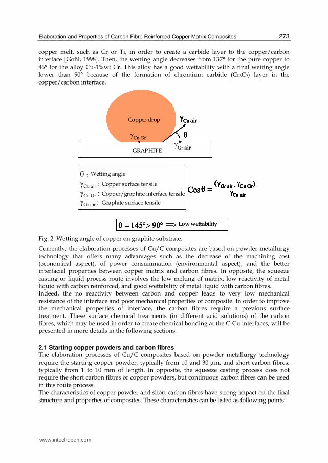
Several processes have been developed to elaborate copper carbon composites through hot pressing or squeeze casting [Praksan et al., 1997][Koráb et al., 2002]. However, all processes are difficultly perfecting and too expensive for elaboration of thin sheet materials. Besides, the poor wettability of carbon fibres with copper lead to low interfacial strength of composites obtained with casting or liquid process routes. This low wettability results often by large angle of the copper drop on graphite substrate (fig 2.). Then, one solution is the improvement of this wettability between copper and graphite with alloying element with
www.intechopen.com
Elaboration and Properties of Carbon Fibre Reinforced Copper Matrix Composites
273
copper melt, such as Cr or Ti, in order to create a carbide layer to the copper/carbon interface [Goñi, 1998]. Then, the wetting angle decreases from 137° for the pure copper to 46° for the alloy Cu-1%wt Cr. This alloy has a good wettability with a final wetting angle lower than 90° because of the formation of chromium carbide (Cr3C2) layer in the copper/carbon interface.
CUIVRE (liq)
GRAPHITE
γCu Gr
γCu air
γGr air
θ
θ : angle de mouillageγCu air : tension superficielle cuivre-airγCu Gr : tension superficielle cuivre-graphiteγGr air : tension superficielle graphite-air
(γGr air -
γCu Gr)γCu air
Cos θ =
CUIVRE (liq)
GRAPHITE
γCu Gr
γCu
γGr air
Copper drop
GRAPHITE
γCu Gr
γCu
γGr air
θ
θ : Wetting angle
γCu air : Copper surface tensileγCu Gr : γGr air :
(γGr air -
γCu Gr)γCu air
Cos θ = (γGr air -
γCu Gr)γCu air
(γGr air -
γCu Gr)γCu air
Cos θ =
θ = 145°> 90°θ = 145°> 90° Low wettability
Copper/graphite interface tensile
Graphite surface tensile
CUIVRE (liq)
GRAPHITE
γCu Gr
γCu air
γGr air
CUIVRE (liq)
GRAPHITE
γCu Gr
γCu air
γGr air
θ
θ : angle de mouillageγCu air : tension superficielle cuivre-airγCu Gr : tension superficielle cuivre-graphiteγGr air : tension superficielle graphite-air
(γGr air -
γCu Gr)γCu air
Cos θ = (γGr air -
γCu Gr)γCu air
(γGr air -
γCu Gr)γCu air
Cos θ =
CUIVRE (liq)
GRAPHITE
γCu Gr
γCu
γGr air
Copper drop
GRAPHITE
γCu Gr
γCu
γGr air
θ
θ : Wetting angle
γCu air : Copper surface tensileγCu Gr : γGr air :
(γGr air -
γCu Gr)γCu air
(γGr air -
γCu Gr)γCu air
Cos θ = (γGr air -
γCu Gr)γCu air
(γGr air -
γCu Gr)γCu air
Cos θ =
θ = 145°> 90°θ = 145°> 90° Low wettability
Copper/graphite interface tensile
Graphite surface tensile
Fig. 2. Wetting angle of copper on graphite substrate.
Currently, the elaboration processes of Cu/C composites are based on powder metallurgy technology that offers many advantages such as the decrease of the machining cost (economical aspect), of power consummation (environmental aspect), and the better interfacial properties between copper matrix and carbon fibres. In opposite, the squeeze casting or liquid process route involves the low melting of matrix, low reactivity of metal liquid with carbon reinforced, and good wettability of metal liquid with carbon fibres. Indeed, the no reactivity between carbon and copper leads to very low mechanical resistance of the interface and poor mechanical properties of composite. In order to improve the mechanical properties of interface, the carbon fibres require a previous surface treatment. These surface chemical treatments (in different acid solutions) of the carbon fibres, which may be used in order to create chemical bonding at the C-Cu interfaces, will be presented in more details in the following sections.
2.1 Starting copper powders and carbon fibres The elaboration processes of Cu/C composites based on powder metallurgy technology require the starting copper powder, typically from 10 and 30 μm, and short carbon fibres, typically from 1 to 10 mm of length. In opposite, the squeeze casting process does not require the short carbon fibres or copper powders, but continuous carbon fibres can be used in this route process. The characteristics of copper powder and short carbon fibres have strong impact on the final structure and properties of composites. These characteristics can be listed as following points:
www.intechopen.com
Advances in Composites Materials - Ecodesign and Analysis
274
- Ratio size between copper particles and diameter of carbon fibres. High ratio is favourable to better distributions of carbon fibres in copper matrix, and a ratio higher that one is usually recommended.
- The electrolytic copper powders (dendritic shape) lead to better mixing with short carbon fibres that copper powders obtained by atomisation (spherical shape).
- The length of carbon fibres must be 100 times greater than their diameter in order to obtain the optimal thermo-mechanical properties.
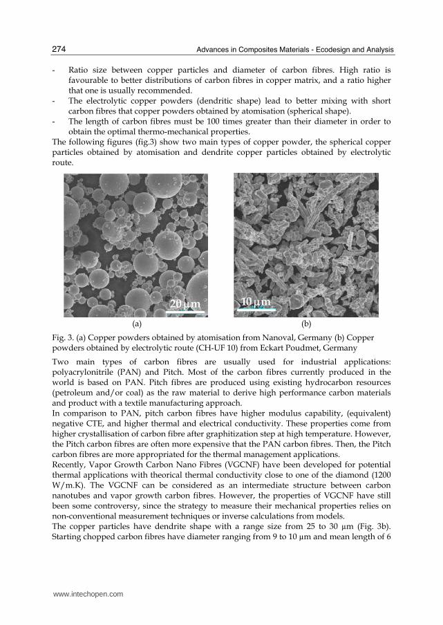
The following figures (fig.3) show two main types of copper powder, the spherical copper particles obtained by atomisation and dendrite copper particles obtained by electrolytic route.
20 μm20 μm
10 μm10 μm
(a) (b)
Fig. 3. (a) Copper powders obtained by atomisation from Nanoval, Germany (b) Copper powders obtained by electrolytic route (CH-UF 10) from Eckart Poudmet, Germany
Two main types of carbon fibres are usually used for industrial applications: polyacrylonitrile (PAN) and Pitch. Most of the carbon fibres currently produced in the world is based on PAN. Pitch fibres are produced using existing hydrocarbon resources (petroleum and/or coal) as the raw material to derive high performance carbon materials and product with a textile manufacturing approach. In comparison to PAN, pitch carbon fibres have higher modulus capability, (equivalent) negative CTE, and higher thermal and electrical conductivity. These properties come from higher crystallisation of carbon fibre after graphitization step at high temperature. However, the Pitch carbon fibres are often more expensive that the PAN carbon fibres. Then, the Pitch carbon fibres are more appropriated for the thermal management applications. Recently, Vapor Growth Carbon Nano Fibres (VGCNF) have been developed for potential thermal applications with theorical thermal conductivity close to one of the diamond (1200 W/m.K). The VGCNF can be considered as an intermediate structure between carbon nanotubes and vapor growth carbon fibres. However, the properties of VGCNF have still been some controversy, since the strategy to measure their mechanical properties relies on non-conventional measurement techniques or inverse calculations from models. The copper particles have dendrite shape with a range size from 25 to 30 µm (Fig. 3b). Starting chopped carbon fibres have diameter ranging from 9 to 10 µm and mean length of 6
www.intechopen.com
Elaboration and Properties of Carbon Fibre Reinforced Copper Matrix Composites
275
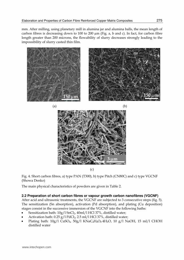
mm. After milling, using planetary mill in alumina jar and alumina balls, the mean length of carbon fibres is decreasing down to 100 to 200 µm (Fig. a, b and c). In fact, for carbon fibre length greater than 200 microns, the flowability of slurry decreases strongly leading to the impossibility of slurry casted thin film.
20 μm
150 μm
20 μm
150 μm
150 μm150 μm
(a) (b)
3 μm3 μm
(c)
Fig. 4. Short carbon fibres, a) type PAN (T300), b) type Pitch (CN80C) and c) type VGCNF (Showa Denko)
The main physical characteristics of powders are given in Table 2.
2.2 Preparation of short carbon fibres or vapour growth carbon nanofibres (VGCNF) After acid and ultrasonic treatments, the VGCNF are subjected to 3 consecutive steps (fig. 5). The sensitization (Sn absorption), activation (Pd absorption), and plating (Cu deposition) stages consist in the successive immersion of the VGCNF into the following baths: • Sensitization bath: 10g/l SnCl2, 40ml/l HCl 37%, distilled water; • Activation bath: 0.25 g/l PdCl2, 2.5 ml/l HCl 37%, distilled water; • Plating bath: 10g/l CuSO4, 50g/l KNaC4H4O6⋅4H2O, 10 g/l NaOH, 15 ml/l CHOH
distilled water
www.intechopen.com
Advances in Composites Materials - Ecodesign and Analysis
276
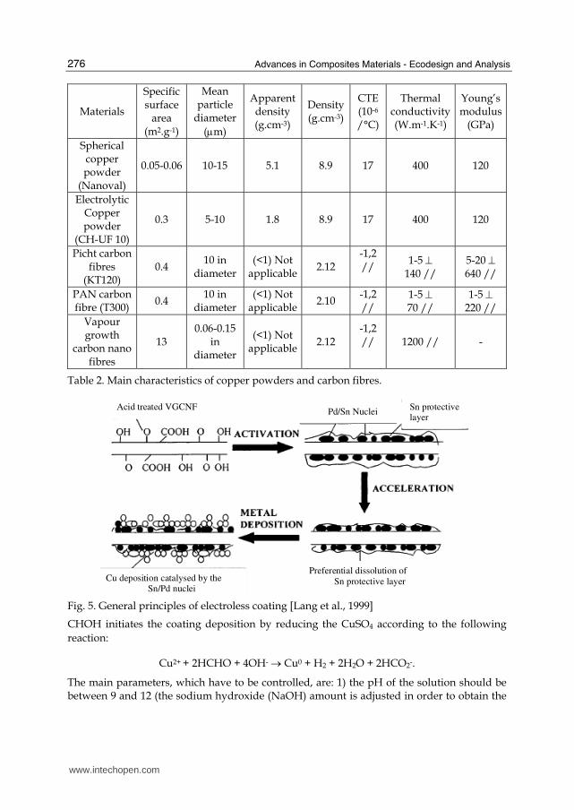
Materials
Specific surface
area (m2.g-1)
Mean particle
diameter
(μm)
Apparent density (g.cm-3)
Density(g.cm-3)
CTE (10-6
/°C)
Thermal conductivity (W.m-1.K-1)
Young’s modulus
(GPa)
Spherical copper powder
(Nanoval)
0.05-0.06 10-15 5.1 8.9 17 400 120
Electrolytic Copper powder
(CH-UF 10)
0.3 5-10 1.8 8.9 17 400 120
Picht carbon fibres
(KT120) 0.4
10 in diameter
(<1) Not applicable
2.12 -1,2 //
1-5 ⊥ 140 //
5-20 ⊥ 640 //
PAN carbon fibre (T300)
0.4 10 in
diameter (<1) Not
applicable2.10
-1,2 //
1-5 ⊥ 70 //
1-5 ⊥ 220 //
Vapour growth
carbon nano fibres
13 0.06-0.15
in diameter
(<1) Not applicable
2.12 -1,2 //
1200 // -
Table 2. Main characteristics of copper powders and carbon fibres.
Acid treated VGCNF
Cu deposition catalysed by theSn/Pd nuclei
Pd/Sn NucleiSn protectivelayer
Preferential dissolution of
Sn protective layer
Fig. 5. General principles of electroless coating [Lang et al., 1999]
CHOH initiates the coating deposition by reducing the CuSO4 according to the following
reaction:
Cu2+ + 2HCHO + 4OH- → Cu0 + H2 + 2H2O + 2HCO2-.
The main parameters, which have to be controlled, are: 1) the pH of the solution should be between 9 and 12 (the sodium hydroxide (NaOH) amount is adjusted in order to obtain the
www.intechopen.com
Elaboration and Properties of Carbon Fibre Reinforced Copper Matrix Composites
277
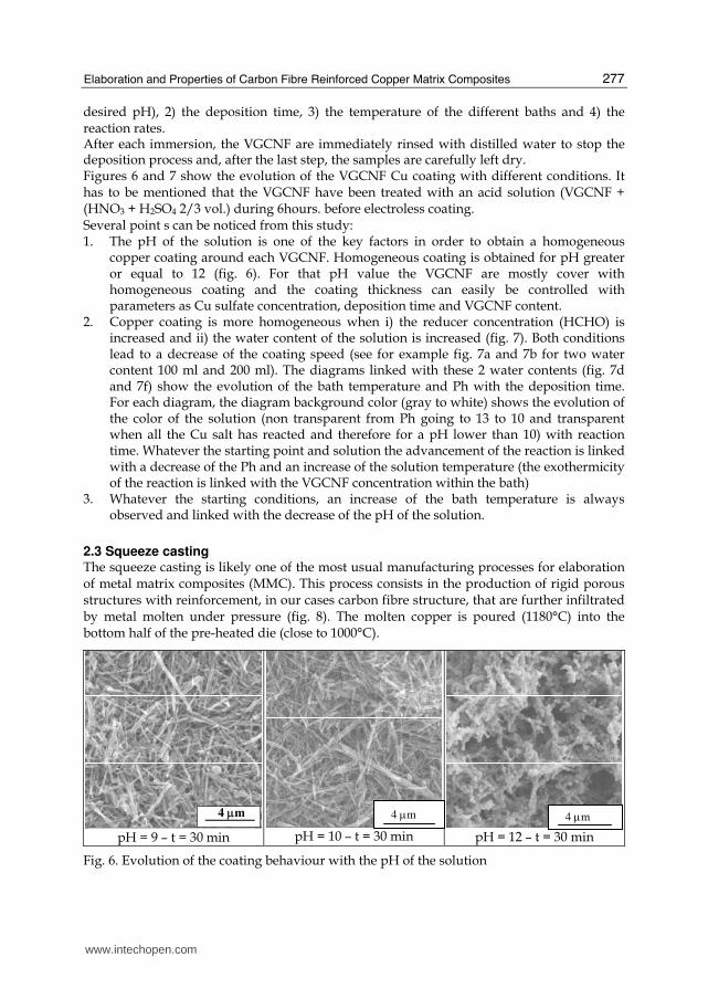
desired pH), 2) the deposition time, 3) the temperature of the different baths and 4) the reaction rates. After each immersion, the VGCNF are immediately rinsed with distilled water to stop the deposition process and, after the last step, the samples are carefully left dry. Figures 6 and 7 show the evolution of the VGCNF Cu coating with different conditions. It has to be mentioned that the VGCNF have been treated with an acid solution (VGCNF + (HNO3 + H2SO4 2/3 vol.) during 6hours. before electroless coating. Several point s can be noticed from this study: 1. The pH of the solution is one of the key factors in order to obtain a homogeneous
copper coating around each VGCNF. Homogeneous coating is obtained for pH greater or equal to 12 (fig. 6). For that pH value the VGCNF are mostly cover with homogeneous coating and the coating thickness can easily be controlled with parameters as Cu sulfate concentration, deposition time and VGCNF content.
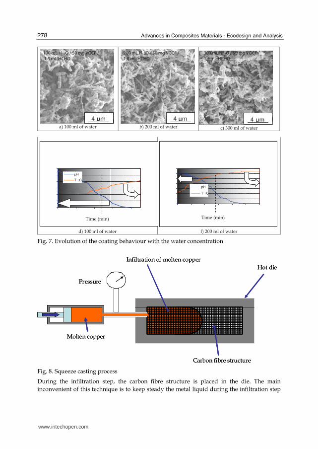
2. Copper coating is more homogeneous when i) the reducer concentration (HCHO) is increased and ii) the water content of the solution is increased (fig. 7). Both conditions lead to a decrease of the coating speed (see for example fig. 7a and 7b for two water content 100 ml and 200 ml). The diagrams linked with these 2 water contents (fig. 7d and 7f) show the evolution of the bath temperature and Ph with the deposition time. For each diagram, the diagram background color (gray to white) shows the evolution of the color of the solution (non transparent from Ph going to 13 to 10 and transparent when all the Cu salt has reacted and therefore for a pH lower than 10) with reaction time. Whatever the starting point and solution the advancement of the reaction is linked with a decrease of the Ph and an increase of the solution temperature (the exothermicity of the reaction is linked with the VGCNF concentration within the bath)
3. Whatever the starting conditions, an increase of the bath temperature is always observed and linked with the decrease of the pH of the solution.
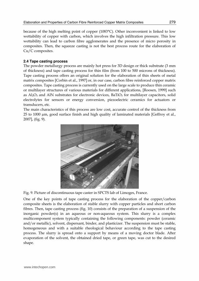
2.3 Squeeze casting The squeeze casting is likely one of the most usual manufacturing processes for elaboration of metal matrix composites (MMC). This process consists in the production of rigid porous structures with reinforcement, in our cases carbon fibre structure, that are further infiltrated by metal molten under pressure (fig. 8). The molten copper is poured (1180°C) into the bottom half of the pre-heated die (close to 1000°C).
4 μm
pH = 9 – t = 30 min pH = 10 – t = 30 min
pH = 12 – t = 30 min
Fig. 6. Evolution of the coating behaviour with the pH of the solution
4 μm 4 μm
www.intechopen.com
Advances in Composites Materials - Ecodesign and Analysis
278
a) 100 ml of water b) 200 ml of water c) 300 ml of water
d) 100 ml of water f) 200 ml of water
pH
C
pH
Time (min) Time (min)
100 mL H 2O / 50 mg VGCF /
1,5 mL HCHO
200 mL H 2O / 50 mg VGCF /
1,5 mL HCHO
300 mL H 2O / 50 mg VGCF /
1,5 mL HCHO
4 μm 4 μm 4 μm
Fig. 7. Evolution of the coating behaviour with the water concentration
Molten copper
Pressure
Carbon fibre structure
Hot die
Infiltration of molten copper
Molten copper
Pressure
Carbon fibre structure
Hot die
Infiltration of molten copper
Fig. 8. Squeeze casting process
During the infiltration step, the carbon fibre structure is placed in the die. The main
inconvenient of this technique is to keep steady the metal liquid during the infiltration step
www.intechopen.com
Elaboration and Properties of Carbon Fibre Reinforced Copper Matrix Composites
279
because of the high melting point of copper (1083°C). Other inconvenient is linked to low
wettability of copper with carbon, which involves the high infiltration pressure. This low
wettability can lead to carbon fibre agglomerates and the presence of micro porosity in
composites. Then, the squeeze casting is not the best process route for the elaboration of
Cu/C composites.
2.4 Tape casting process The powder metallurgy process are mainly hot press for 3D design or thick substrate (3 mm
of thickness) and tape casting process for thin film (from 100 to 500 microns of thickness).
Tape casting process offers an original solution for the elaboration of thin sheets of metal
matrix composites [Corbin et al., 1997] or, in our case, carbon fibre reinforced copper matrix
composites. Tape casting process is currently used on the large scale to produce thin ceramic
or multilayer structures of various materials for different applications, [Roosen, 1999] such
as Al2O3 and AlN substrates for electronic devices, BaTiO3 for multilayer capacitors, solid
electrolytes for sensors or energy conversion, piezoelectric ceramics for actuators or
transducers, etc.
The main characteristics of this process are low cost, accurate control of the thickness from
25 to 1000 µm, good surface finish and high quality of laminated materials [Geffroy et al.,
2007], (fig. 9).
Fig. 9. Picture of discontinuous tape caster in SPCTS lab of Limoges, France.
One of the key points of tape casting process for the elaboration of the copper/carbon
composite sheets is the elaboration of stable slurry with copper particles and short carbon
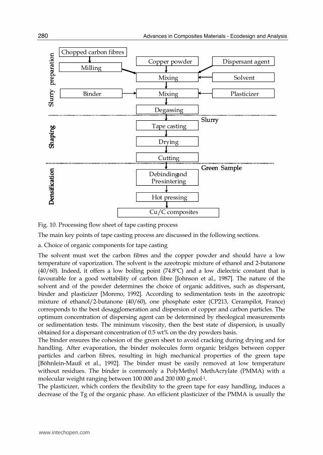
fibres. Then, tape casting process (fig. 10) consists of the preparation of a suspension of the
inorganic powder(s) in an aqueous or non-aqueous system. This slurry is a complex
multicomponent system typically containing the following components: powder (ceramic
and/or metallic), solvent, dispersant, binder, and plasticizer. The suspension must be stable,
homogeneous and with a suitable rheological behaviour according to the tape casting
process. The slurry is spread onto a support by means of a moving doctor blade. After
evaporation of the solvent, the obtained dried tape, or green tape, was cut to the desired
shape.
www.intechopen.com
Advances in Composites Materials - Ecodesign and Analysis
280
Drying
Tape casting
Degassing
Dispersant agent
Mixing
Copper powder
Mixing
Milling
Solvent
Binder Plasticizer
Cutting
DebindingandPre-sintering
Slurry
Green Sample
Hot pressing
Copper/carbon composites
pre
par
atio
nD
ensi
fica
tio
nSh
apin
gChopped carbon fibres
Drying
Tape casting
Degassing
Dispersant agent
Mixing
Copper powder
Mixing
Milling
Solvent
Binder Plasticizer
Cutting
DebindingandPre-sintering
Hot pressing
Cu/C composites
Slu
rry
Den
sifi
cati
on
Shap
ing
Drying
Tape casting
Degassing
Dispersant agent
Mixing
Copper powder
Mixing
Milling
Solvent
Binder Plasticizer
Cutting
DebindingandPre-sintering
Slurry
Green Sample
Hot pressing
Copper/carbon composites
pre
par
atio
nD
ensi
fica
tio
nSh
apin
gChopped carbon fibres
Drying
Tape casting
Degassing
Dispersant agent
Mixing
Copper powder
Mixing
Milling
Solvent
Binder Plasticizer
Cutting
DebindingandPre-sintering
Hot pressing
Cu/C composites
Slu
rry
Den
sifi
cati
on
Shap
ing
Fig. 10. Processing flow sheet of tape casting process
The main key points of tape casting process are discussed in the following sections.
a. Choice of organic components for tape casting
The solvent must wet the carbon fibres and the copper powder and should have a low
temperature of vaporization. The solvent is the azeotropic mixture of ethanol and 2-butanone
(40/60). Indeed, it offers a low boiling point (74.8ºC) and a low dielectric constant that is
favourable for a good wettability of carbon fibre [Johnson et al., 1987]. The nature of the
solvent and of the powder determines the choice of organic additives, such as dispersant,
binder and plasticizer [Moreno, 1992]. According to sedimentation tests in the azeotropic
mixture of ethanol/2-butanone (40/60), one phosphate ester (CP213, Cerampilot, France)
corresponds to the best desagglomeration and dispersion of copper and carbon particles. The
optimum concentration of dispersing agent can be determined by rheological measurements
or sedimentation tests. The minimum viscosity, then the best state of dispersion, is usually
obtained for a dispersant concentration of 0.5 wt% on the dry powders basis.
The binder ensures the cohesion of the green sheet to avoid cracking during drying and for
handling. After evaporation, the binder molecules form organic bridges between copper
particles and carbon fibres, resulting in high mechanical properties of the green tape
[Böhnlein-Mauß et al., 1992]. The binder must be easily removed at low temperature
without residues. The binder is commonly a PolyMethyl MethAcrylate (PMMA) with a
molecular weight ranging between 100 000 and 200 000 g.mol-1.
The plasticizer, which confers the flexibility to the green tape for easy handling, induces a
decrease of the Tg of the organic phase. An efficient plasticizer of the PMMA is usually the
www.intechopen.com
Elaboration and Properties of Carbon Fibre Reinforced Copper Matrix Composites
281
dibutyl phtalate or polyethylene glycol with a low molecular weight close to 300 g.mol-1. A
good compromise between the flexibility and the mechanical strength of the green tape was
obtained for a binder/plasticizer ratio close from 1 to 1.5.
b. Slurry preparation and tape casting
The tape casting suspension is prepared in two steps. The first one consists in dispersing, by
planetary milling, the copper powder and carbon chopped fibres in 2-butanone/ethanol
solvent with phosphate ester as dispersant. The binder and the plasticizer are added to the
suspension in a second step and the complete slurry was homogenised, also by planetary
milling, but at a lower rotating velocity. After homogenization, the slurry is degassed and
directly casted onto a siliconed Mylar carrier film with a doctor blade. The doctor blade
speed is fixed at 0.5 m.min-1 with a gap of 0.5 mm. The solvent evaporation is carried out at
room temperature under air.
c. Green tape
The geometrical density of the green tapes varying from 2 to 2.5 g.cm-3 corresponds to a
relative density ranging from 0.55 to 0.65 of TD (theoretical density), that suggests a rather
good arrangement of particles, whereas the particle shapes, like short fibres or dendrite
copper particles, are not favourable to a good compaction. However, the carbon fibres are
oriented in the casting plan due to shear imposed during tape casting.
d. Thermal treatments
The organic components are removed during a thermal treatment at low temperature, i.e.
debinding. The composites are then pre-sintering at higher temperature. The resulting
composite structures have sufficient strength and flexibility for handling, but still present an
important porosity. The thin sheets are then subsequently fully sintered by hot pressing (fig.
11?). In this densification step, 5 or 10 sheets (with thickness equal to 200 µm) can be pressed
together for the elaboration of thick systems.
e. Debinding and pre-sintering
In the first step of firing, the organic additives, i.e. the binder, plastizicer and dispersant are burned out carefully. The removal of plasticizer and binder occurs, under air, between 120ºC and 350ºC, whereas the extraction, under nitrogen, is performed between 140 and 400ºC. Due to copper oxidation starting at 150ºC under air, debinding of copper/carbon composite green sheets are performed at 350°C under nitrogen. In the second step of firing, the copper matrix is pre-sintered at 750ºC during 30 mn in nitrogen. The resulting composite has a sufficient strength and flexibility for handling, but still presents an important porosity (20-30 % in volume), which results from the presence of carbon fibres. The densification of the copper/carbon composites starts at about 650ºC.
f. Densification by hot pressing
The pre-sintered individual tapes or multilayers are introduced between the two pistons of the steel mould which were heated, under vacuum (0.66 Pa), by induction system and regulation monitor. The usual conditions of hot pressing correspond to 650ºC with a heating rate of 25ºC.min-1 under 50 MPa during 1 min. This last step of densification by hot pressing is presented in more details in the next section.
www.intechopen.com
Advances in Composites Materials - Ecodesign and Analysis
282
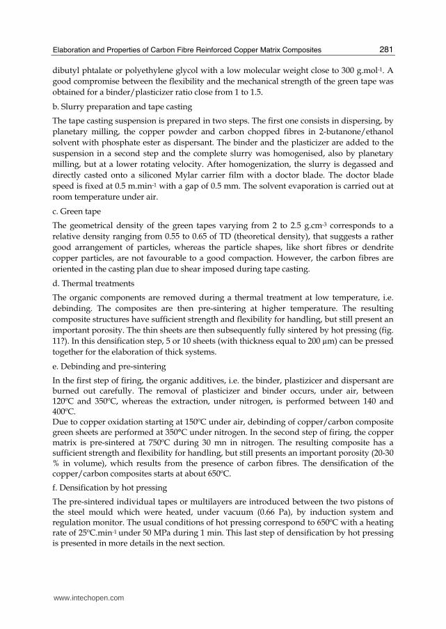
2.5 Hot pressing Hot pressing process consists firstly in the preparation of powders mixing. This mixing, which contains ceramic, metallic powders and lubricant agents, must be stable and homogeneous. The bad wettability of the carbon fibres by copper and the non reactivity between carbon and copper led to the formation of a stable porosity between the copper matrix and the carbon fibres during the densification stage. Thus, the full densification of copper/carbon composites is not possible by conventional sintering. Hot pressing technique, [Evans and McColvin, 1976][Jha and Kumar, 1997], under controlled atmosphere, is finally used in order to obtain fully dense materials.
Pressing
lubricant agent
Mixing
Copper powder
Milling
Green sample
Hot pressing
Copper/carbon composites
Den
sifi
cati
on
Shap
ing
Chopped carbon fibres
Pressing
lubricant agent
Mixing
Copper powder
Milling
Green
Hot pressing
Copper/carbon composites
Den
sifi
cati
on
Shap
ing
Pressing
lubricant agent
Mixing
Copper powder
Milling
Green sample
Hot pressing
Copper/carbon composites
Den
sifi
cati
on
Shap
ing
Chopped carbon fibres
Pressing
lubricant agent
Mixing
Copper powder
Milling
Green
Hot pressing
Copper/carbon composites
Den
sifi
cati
on
Shap
ing
Fig. 11. Processing flow sheet of hot pressing
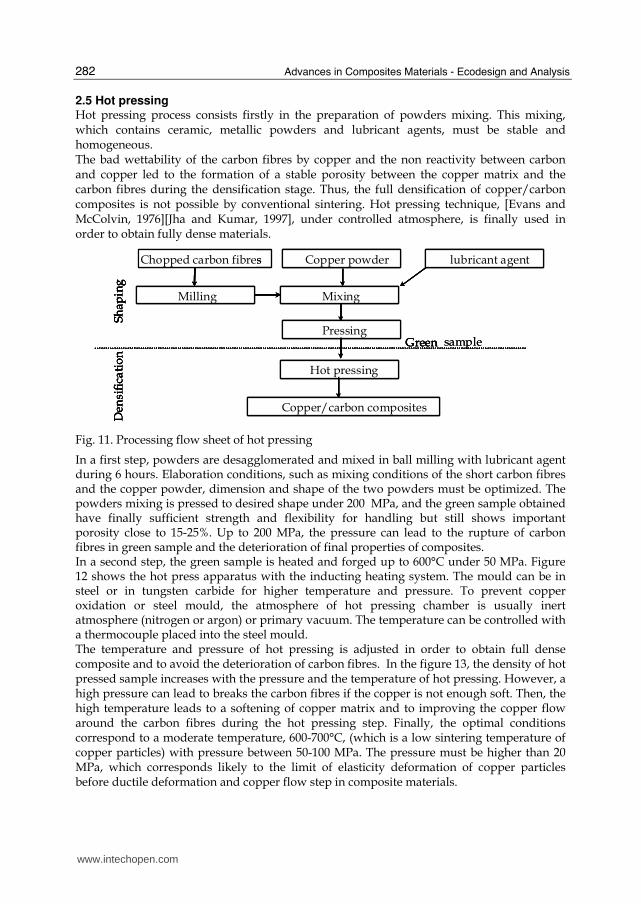
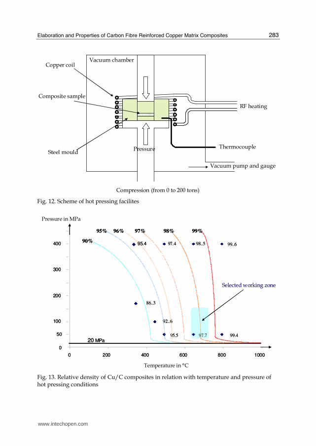
In a first step, powders are desagglomerated and mixed in ball milling with lubricant agent during 6 hours. Elaboration conditions, such as mixing conditions of the short carbon fibres and the copper powder, dimension and shape of the two powders must be optimized. The powders mixing is pressed to desired shape under 200 MPa, and the green sample obtained have finally sufficient strength and flexibility for handling but still shows important porosity close to 15-25%. Up to 200 MPa, the pressure can lead to the rupture of carbon fibres in green sample and the deterioration of final properties of composites. In a second step, the green sample is heated and forged up to 600°C under 50 MPa. Figure 12 shows the hot press apparatus with the inducting heating system. The mould can be in steel or in tungsten carbide for higher temperature and pressure. To prevent copper oxidation or steel mould, the atmosphere of hot pressing chamber is usually inert atmosphere (nitrogen or argon) or primary vacuum. The temperature can be controlled with a thermocouple placed into the steel mould. The temperature and pressure of hot pressing is adjusted in order to obtain full dense composite and to avoid the deterioration of carbon fibres. In the figure 13, the density of hot pressed sample increases with the pressure and the temperature of hot pressing. However, a high pressure can lead to breaks the carbon fibres if the copper is not enough soft. Then, the high temperature leads to a softening of copper matrix and to improving the copper flow around the carbon fibres during the hot pressing step. Finally, the optimal conditions correspond to a moderate temperature, 600-700°C, (which is a low sintering temperature of copper particles) with pressure between 50-100 MPa. The pressure must be higher than 20 MPa, which corresponds likely to the limit of elasticity deformation of copper particles before ductile deformation and copper flow step in composite materials.
www.intechopen.com
Elaboration and Properties of Carbon Fibre Reinforced Copper Matrix Composites
283
Copper coil
RF heating
Vacuum pump and gauge
Vacuum chamber
Thermocouple
Compression (from 0 to 200 tons)
Composite sample
Steel mouldPressure
Copper coil
RF heating
Vacuum pump and gauge
Vacuum chamber
Thermocouple
Compression (from 0 to 200 tons)
Composite sample
Steel mouldPressure
Fig. 12. Scheme of hot pressing facilites
0
50
100
200
300
400
0 200 400 600 800 1000
86..3
92..6
95.5 97.7 99.4
97.4 98..5 99..690%
95% 98% 99%96% 97%
Pressure in MPa
Temperature in °C
95.4
Selected working zone
20 MPa
0
50
100
200
300
400
0 200 400 600 800 1000
86..3
92..6
95.5 97.7 99.4
97.4 98..5 99..690%
95% 98% 99%96% 97%
Pressure in MPa
Temperature in °C
95.4
Selected working zone
20 MPa
Fig. 13. Relative density of Cu/C composites in relation with temperature and pressure of hot pressing conditions
www.intechopen.com
Advances in Composites Materials - Ecodesign and Analysis
284
Besides, a high temperature of hot pressure involves the important technological cost, and it can lead the pre-sinterisation of copper particles, which is prejudicial to suitable softening of copper matrix during the hot pressing. Then, the optimal conditions of hot pressing correspond usually to the best compromise between optimal properties of Cu/C composites and process cost. Finally, the main parameters of hot pressing, such as temperature, time and atmosphere in the thermal properties of the Cu/C composite materials must be adjusted in relation with the optimal mechanical and thermal properties of Cu/C composites.
2.6 Reporting of Cu/C composites Composite heat-sink family shows the highest potential for application in heat sinks for electronic applications. The great advantage of this kind of materials is that they can combine metal, polymer and ceramics in a broad range of different products to tailor the final properties sought. Nevertheless, final properties of composites greatly depends on manufacturing processes. Among the huge amount of different composites, the most efficient and so the most commonly developed for heat dissipation purposes, are metal matrix composites, and most specifically those based on copper and aluminum matrices with a broad range of different reinforcements. Recently, some investigations in epoxy based composites reinforced with an extremely interesting new kind of carbon fibres (Vapour Grown Carbon Fibres, VGCFs) have shown outstanding thermal conductivities, near 650W/mK. These newly developed kinds of micro/nanofibres (commercially available since the nineties) exhibit the highest thermal conductivity of all materials known. Their special structure based on its manufacturing process (they are produced from gases) gives them a high potential to achieve a highly graphitic structure by a proper heat treatment, not achievable in other carbon fibres, thus leading to outstanding physical and mechanical properties. But the main problem encountered with epoxy based composites is their low highest temperature of use. Nevertheless, in any case, these composites could be applied up to a temperature near 120ºC, where polymers can start degrading. Undoubtedly, the most efficient composites for heat sinks are those based on Cu and Al with a number of different reinforcements. In general, metal matrix composites (MMCs) show several improvements in comparison with currently used materials in electronic packaging, among them the following can be underlined: - Lower and tailorable CTE (the higher the volume fraction of reinforcement used, the
lower the CTE is) to be as similar as possible to ceramic substrates. In the present development, in which a suitable electronic packaging component for GaN semiconductor device will be developed, the coefficient of thermal expansion must be as similar as possible to that of the electronic substrate. This reduction of the CTE mismatch supposes, therefore, a reduction of stresses between the components and their substrates during thermal cycling;
- High heat dissipation capability; - Lightweight, suitable for space applications; - High stiffness at high temperatures, being an useful characteristic in order to assure
dimensional stability of electronic components working at high temperatures. Due to their high conductivity, low CTE and lightweight, Al/SiCp (50-70%SiCp) composites represent one of the MMC kinds of materials that have found an easier way to be introduced
www.intechopen.com
Elaboration and Properties of Carbon Fibre Reinforced Copper Matrix Composites
285
into real industrial applications [Luedkte, 2004]. Some manufacturing processes for this type of composites have been developed along the last years (infiltration and squeeze casting) for these materials, so they are already available (it depends very much on size, shape, etc…). Unfortunately, they are extremely difficult to machine, therefore, manufacturing processes must be net or near-net shape, in order to get a really profitable manufacturing process. Another interesting kind of MMCs for heat sinks is Cu/diamond composites. But their main problem, again, is that they are expensive because diamond is expensive and difficult to machine. Looking, at the previous table 1, it can be said that copper based materials are the most promising among MMCs. Most of the composites based on this matrix are reinforced by ceramics (particles, short fibres, and long fibres) in order to reduce their extremely high CTE and match it with those of the semiconductor or other ceramic substrates. Nevertheless, carbon fibres also offer the big advantage of high heat and electrical conductivity. So, MMCs reinforced with long C fibres show excellent thermal conductivity along the fibre direction. Unfortunately, these types of composites are not usable in a broad range of heat sinks, as the excellent thermal conductivity is achieved in surface but not across the thickness. Of major interest are those composites reinforced with short fibres, as although in general terms thermal conductivity is more modest than those reinforced with continuous fibres, they have isotropic properties. In addition, their manufacturing processes are less sophisticated and expensive.
3. Properties of Cu/ C composites
The main properties of Cu/C composites depend strongly of process conditions. One of key points is the improvement of interfacial strength between copper and carbon during process. These main properties obtained by hot pressing and tape casting are discussed and presented in the following parts.
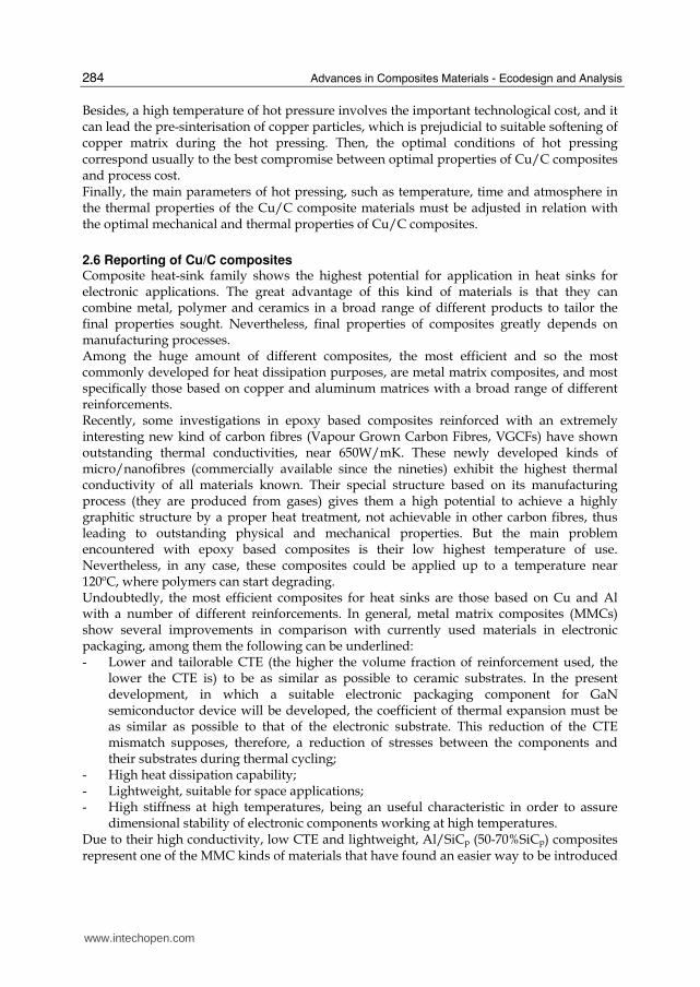
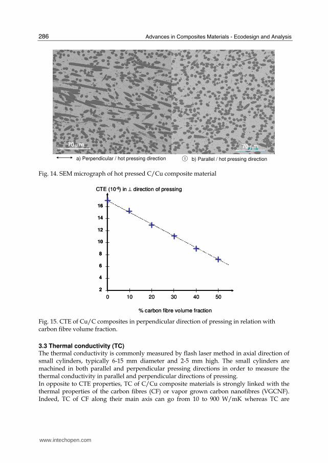
3.1 Microstructure of Cu/C composites The final density of materials is close to 94-98 %, and no specific degradation of carbon fibres is observed in the Cu/C composites materials microstructures. Microstructure characterization (fig. 14) shows strong anisotropy structure between the perpendicular and parallel pressing directions. Carbon fibres are oriented in perpendicular plan of pressing direction due to the strains and stresses imposed by pressing conditions and geometry. It can be expected that carbon fibre orientation leads to anisotropic properties of the Cu/C composites.
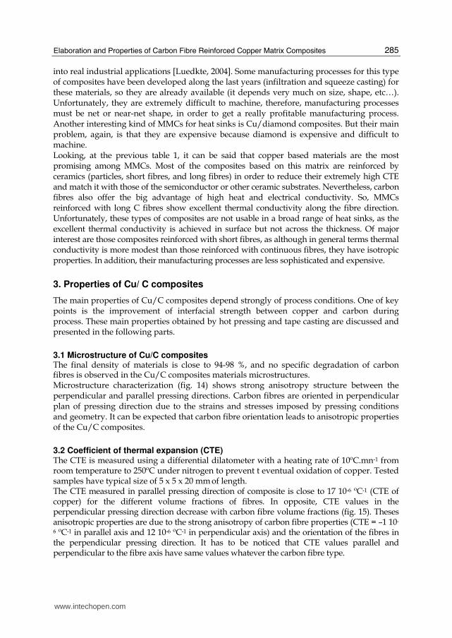
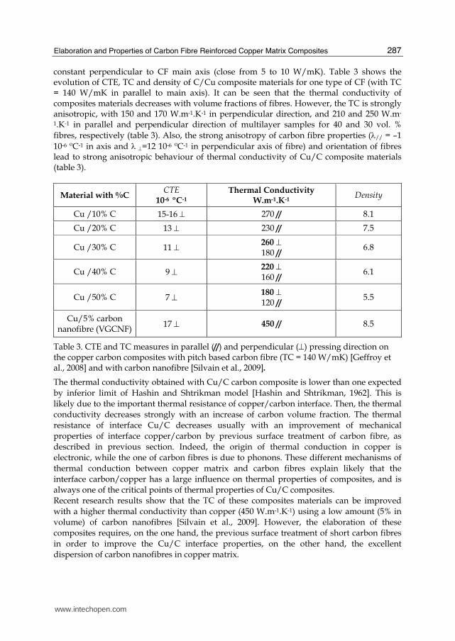
3.2 Coefficient of thermal expansion (CTE) The CTE is measured using a differential dilatometer with a heating rate of 10ºC.mn-1 from room temperature to 250ºC under nitrogen to prevent t eventual oxidation of copper. Tested samples have typical size of 5 x 5 x 20 mm of length. The CTE measured in parallel pressing direction of composite is close to 17 10-6 ºC-1 (CTE of copper) for the different volume fractions of fibres. In opposite, CTE values in the perpendicular pressing direction decrease with carbon fibre volume fractions (fig. 15). Theses anisotropic properties are due to the strong anisotropy of carbon fibre properties (CTE = –1 10-
6 ºC-1 in parallel axis and 12 10-6 ºC-1 in perpendicular axis) and the orientation of the fibres in the perpendicular pressing direction. It has to be noticed that CTE values parallel and perpendicular to the fibre axis have same values whatever the carbon fibre type.
www.intechopen.com
Advances in Composites Materials - Ecodesign and Analysis
286
b) Parallel / hot pressing direction a) Perpendicular / hot pressing direction
70 μm70 μm
b) Parallel / hot pressing direction a) Perpendicular / hot pressing direction
70 μm70 μm
Fig. 14. SEM micrograph of hot pressed C/Cu composite material
CTE (10-6) in ⊥ direction of pressing
% carbon fibre volume fraction
10 20 40 50300
4
6
8
12
10
16
14
2
CTE (10-6) in ⊥ direction of pressing
% carbon fibre volume fraction
10 20 40 50300
4
6
8
12
10
16
14
2
Fig. 15. CTE of Cu/C composites in perpendicular direction of pressing in relation with carbon fibre volume fraction.
3.3 Thermal conductivity (TC) The thermal conductivity is commonly measured by flash laser method in axial direction of small cylinders, typically 6-15 mm diameter and 2-5 mm high. The small cylinders are machined in both parallel and perpendicular pressing directions in order to measure the thermal conductivity in parallel and perpendicular directions of pressing. In opposite to CTE properties, TC of C/Cu composite materials is strongly linked with the thermal properties of the carbon fibres (CF) or vapor grown carbon nanofibres (VGCNF). Indeed, TC of CF along their main axis can go from 10 to 900 W/mK whereas TC are
www.intechopen.com
Elaboration and Properties of Carbon Fibre Reinforced Copper Matrix Composites
287
constant perpendicular to CF main axis (close from 5 to 10 W/mK). Table 3 shows the evolution of CTE, TC and density of C/Cu composite materials for one type of CF (with TC = 140 W/mK in parallel to main axis). It can be seen that the thermal conductivity of composites materials decreases with volume fractions of fibres. However, the TC is strongly anisotropic, with 150 and 170 W.m-1.K-1 in perpendicular direction, and 210 and 250 W.m-
1.K-1 in parallel and perpendicular direction of multilayer samples for 40 and 30 vol. %
fibres, respectively (table 3). Also, the strong anisotropy of carbon fibre properties (λ// = –1
10-6 ºC-1 in axis and λ ⊥=12 10-6 ºC-1 in perpendicular axis of fibre) and orientation of fibres lead to strong anisotropic behaviour of thermal conductivity of Cu/C composite materials (table 3).
Material with %C CTE
10-6 ºC-1 Thermal Conductivity
W.m-1.K-1 Density
Cu /10% C 15-16 ⊥ 270 // 8.1
Cu /20% C 13 ⊥ 230 // 7.5
Cu /30% C 11 ⊥ 260 ⊥ 180 //
6.8
Cu /40% C 9 ⊥ 220 ⊥ 160 //
6.1
Cu /50% C 7 ⊥ 180 ⊥ 120 //
5.5
Cu/5% carbon nanofibre (VGCNF)
17 ⊥ 450 // 8.5
Table 3. CTE and TC measures in parallel (//) and perpendicular (⊥) pressing direction on the copper carbon composites with pitch based carbon fibre (TC = 140 W/mK) [Geffroy et al., 2008] and with carbon nanofibre [Silvain et al., 2009].
The thermal conductivity obtained with Cu/C carbon composite is lower than one expected
by inferior limit of Hashin and Shtrikman model [Hashin and Shtrikman, 1962]. This is likely due to the important thermal resistance of copper/carbon interface. Then, the thermal conductivity decreases strongly with an increase of carbon volume fraction. The thermal resistance of interface Cu/C decreases usually with an improvement of mechanical
properties of interface copper/carbon by previous surface treatment of carbon fibre, as described in previous section. Indeed, the origin of thermal conduction in copper is electronic, while the one of carbon fibres is due to phonons. These different mechanisms of
thermal conduction between copper matrix and carbon fibres explain likely that the interface carbon/copper has a large influence on thermal properties of composites, and is always one of the critical points of thermal properties of Cu/C composites. Recent research results show that the TC of these composites materials can be improved
with a higher thermal conductivity than copper (450 W.m-1.K-1) using a low amount (5% in volume) of carbon nanofibres [Silvain et al., 2009]. However, the elaboration of these composites requires, on the one hand, the previous surface treatment of short carbon fibres
in order to improve the Cu/C interface properties, on the other hand, the excellent dispersion of carbon nanofibres in copper matrix.
www.intechopen.com
Advances in Composites Materials - Ecodesign and Analysis
288
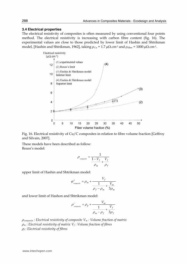
3.4 Electrical properties The electrical resistivity of composites is often measured by using conventional four points method. The electrical resistivity is increasing with carbon fibre content (fig. 16). The experimental values are close to those predicted by lower limit of Hashin and Shtrikman
model, [Hashin and Shtrikman, 1962], taking ρCu = 1.7 μΩ.cm-1 and ρfibre = 1000 μΩ.cm-1.
Fig. 16. Electrical resistivity of Cu/C composites in relation to fibre volume fraction [Geffroy and Silvain, 2007].
These models have been described as follow: Reuss’s model:
1
1compositef f
m f
V Vρ
ρ ρ= − +
upper limit of Hashin and Shtrikman model:
1
3
composite
fm
m
f m m
V
Vϕ ρ
ρ ρ ρ+ = +
+−
and lower limit of Hashon and Shtrikman model:
1
3
composite
mp
f
m f f
V
Vρ ρ
ρ ρ ρ− = +
+−
ρcomposite : Electrical resistivity of composite Vm : Volume fraction of matrix ρm : Electrical resistivity of matrix Vf : Volume fraction of fibres ρf : Electrical resistivity of fibres
www.intechopen.com
Elaboration and Properties of Carbon Fibre Reinforced Copper Matrix Composites
289
This behaviour is linked to a good electrical contact between carbon fibres and copper matrix and to a low porosity at matrix/copper interfaces. Indeed, the both copper and fibres present a similar mechanism of electrical conduction with free electrons. This involves that the electrical resistance of interface copper /carbon has a low impact on electrical resistivity of composite.
4. Potential applications of Cu/C composites
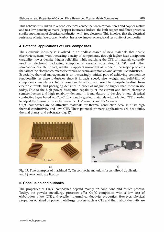
The electronic industry is involved in an endless search of new materials that enable electronic systems with increasing density of components, through higher heat dissipation capability, lower density, higher reliability while matching the CTE of materials currently used in electronic packaging components, ceramic substrates, Si, SiC and other semiconductors, etc. In fact, reliability appears nowadays as is one of the major problems that affect the electronics, microelectronics, telecom, automotive, and aeronautic industries. Especially, thermal management is an increasingly critical part of achieving competitive functionality in these industries since it impacts speed, size, weight and reliability of components, mainly for future components which will need to dissipate heating from electric currents and packaging densities in order of magnitude higher than those in use today. Due to the high power dissipation capability of the current and future electronic semiconductors and high reliability demand, it is mandatory to develop a new electrical conductive layer based on Cu/C functionally graded materials with adapted CTE in order to adjust the thermal stresses between the FGM ceramic and the Si wafer. Cu/C composites are so attractive materials for thermal conduction because of its high thermal conductivity and low CTE. Their potential primary applications are heat sinks, thermal planes, and substrates (fig. 17).
10
mm 15 mm
a) b) Fig. 17. Two examples of machined C/Cu composite materials for a) railroad application and b) aeronautic application
5. Conclusion and outlooks
The properties of Cu/C composites depend mainly on conditions and routes process. Today, the powder metallurgy processes offer Cu/C composites with a low cost of elaboration, a low CTE and excellent thermal conductivity properties. However, physical properties obtained by power metallurgy process such as CTE and thermal conductivity are
www.intechopen.com
Advances in Composites Materials - Ecodesign and Analysis
290
strongly anisotropic. In additional, the lack of interfacial strength between copper and carbon requires a previous surface treatment of short carbon fibres in order to improve the interface properties between copper matrix and carbon fibres. Recent research developments suggest that the thermal conductivity of these composites materials should be largely improved by using nanofibres with a higher thermal conductivity than copper (up to 400 W.m-1.K-1).
6. References
Ang L.M. et al ; (1999). Electroless plating of metals onto carbon nanotubes activated by a single-step activation method, Chemistry of Materials, vol. 11 , 2115-2118 .
Böhnlein-Mauß J.; Sigmund W.; Wegner G.; Meyer W.H.; Heßel F.; Seitz K.; Roosen A., (1992). The function of polymers in the tape casting of alumina, Advan. Mater. , nº2, 73-81.
Corbin S.F.; Zhao-jie X.; Henien H.; Apte P.S., (1999), Functionally grated metal /ceramic composites by tape casting, lamination and infiltration, Mater. Sci. and Eng., 192-203.
Evans R.W; McColvin M., (1976). Hot forged copper powder compacts, Powder Metall., nº4, 202-209.
Geffroy, P.M.; Chartier T.; Silvain J.F., (2007). Preparation by tape casting and hot pressing of copper carbon composites films, Journal of the European Ceramic Society, 27(1): 291-299.
Geffroy, P.M.; Silvain J.F., (2007). Structural and thermal properties of hot pressed Cu/C matrix composites materials used for the thermal management of high power electronic devices, Materials Science Forum 534-536 (PART 2), 1505-1508.
Geffroy, P.M.; Mathias J.-D.; Silvain J.F., (2008). Heat sink material selection in electronic devices by computational approach , Advanced Engineering Materials 10 (4), 400-405.
Goñi, (1998), Elaboration de composites cuivre carbone, PhD, University of Bordeaux. Hashin Z. and Shtrikman S., (1962). On some variational principles in anisotropic and
nonhomogeneous elasticity, J. Mechan. Phys. Solids, vol. 10, 335-342. Jha A.K.; Kumar S., (1997). Investigations into the high-speed forging of sintered copper
powder strips, Journal of Materials Processing Technology, 1997, 71, 394-401. Johnson R. E.; Morrison J.; Morrison W.H., (1987). Ceramic Powder dispersion in
nonaqueous systems, Advances in ceramics, vol. 21: Ceramic Powder Science, The Am. ceram. Soc. Inc., 173-197.
Koráb J.; Stefánik P.; Kavecký S.; Sebo P.; Korb G., (2002). Thermal expansion of cross-ply and woven carbon fibre-copper matrix composites, Composites Part A, 33, 133-136.
Korb G.; Buchgrader W.; Schubert T., (1998). Thermophysical properties and microstructure of short carbon fibre reinforced Cu-matrix composites made by electroless copper coating or powder metallurgical route respectively, IEEE/CPMT Berlin, Int’l Electronics Manufacturing Technology Symposium, 27-28 April, 1998.
Luedkte A., (2004). Thermal management materials for high-performance applications, Advan. Eng. Mater., vol 6, nº3, 142-144.
Moreno R., (1992). The role of slip additives in tape-casting technology: Part I- Solvents and Dispersants, Am. Ceram. Soc. Bull. , vol. 71, Nº10, 1521-1530.
Praksan K.; Palaniappan S.; Seshan S. (1997). Thermal expansion characteristics of cast Cu based metal matrix composites, Composites Part A, 28, 1019-1022.
Roosen A., (1998). Basic requirements for tape casting of ceramic powders, Ceramic Powder Science, vol. 1, Part B, 675-692.
Silvain J.-F.; Vincent C; Heintz J.-M.; Chandra N., (2009). Novel processing and characterization of Cu/CNF nanocomposite for high thermal conductivity applications, Composites Science and Technology, vol. 69, 2474–2484.
www.intechopen.com
Advances in Composite Materials - Ecodesign and AnalysisEdited by Dr. Brahim Attaf
ISBN 978-953-307-150-3Hard cover, 642 pagesPublisher InTechPublished online 16, March, 2011Published in print edition March, 2011
InTech EuropeUniversity Campus STeP Ri Slavka Krautzeka 83/A 51000 Rijeka, Croatia Phone: +385 (51) 770 447 Fax: +385 (51) 686 166www.intechopen.com
InTech ChinaUnit 405, Office Block, Hotel Equatorial Shanghai No.65, Yan An Road (West), Shanghai, 200040, China
Phone: +86-21-62489820 Fax: +86-21-62489821
By adopting the principles of sustainable design and cleaner production, this important book opens a newchallenge in the world of composite materials and explores the achieved advancements of specialists in theirrespective areas of research and innovation. Contributions coming from both spaces of academia and industrywere so diversified that the 28 chapters composing the book have been grouped into the following main parts:sustainable materials and ecodesign aspects, composite materials and curing processes, modelling andtesting, strength of adhesive joints, characterization and thermal behaviour, all of which provides an invaluableoverview of this fascinating subject area. Results achieved from theoretical, numerical and experimentalinvestigations can help designers, manufacturers and suppliers involved with high-tech composite materials toboost competitiveness and innovation productivity.
How to referenceIn order to correctly reference this scholarly work, feel free to copy and paste the following:
Pierre-Marie Geffroy, Jean-François Silvain and Jean-Marc Heintz (2011). Elaboration and Properties ofCarbon Fibre Reinforced Copper Matrix Composites, Advances in Composite Materials - Ecodesign andAnalysis, Dr. Brahim Attaf (Ed.), ISBN: 978-953-307-150-3, InTech, Available from:http://www.intechopen.com/books/advances-in-composite-materials-ecodesign-and-analysis/elaboration-and-properties-of-carbon-fibre-reinforced-copper-matrix-composites

© 2011 The Author(s). Licensee IntechOpen. This chapter is distributedunder the terms of the Creative Commons Attribution-NonCommercial-ShareAlike-3.0 License, which permits use, distribution and reproduction fornon-commercial purposes, provided the original is properly cited andderivative works building on this content are distributed under the samelicense.