Embed Size (px)
Citation preview
Centre Scientifique et Technique du Bâtiment 84 avenue Jean Jaurès CHAMPS-SUR-MARNE 77447 Marne-la-Vallée Cedex 2 Tél. : (33) 01 64 68 82 82 Fax : (33) 01 60 05 70 37
Autorisé etnotifié conformément à
l’article 10 de la directive89/106/EEC du Conseil, du
21 décembre 1988, relative aurapprochement des dispositions
législatives, réglementaireset administratives des Etats
membres concernantles produits deconstruction.
MEMBRE DE L’EOTA
European Technical Approval ETA-11/0151 (English language translation, the original version is in French language)
Nom commercial :
Trade name: AT-HP Galvanised Steel
Titulaire :
Holder of approval: SIMPSON STRONGTIE,
ZI Les 4 chemins
85400 St-Gemme-la-Plaine
France
Type générique et utilisation prévue du produit de construction :
Cheville à scellement de type "à injection" en acier galvanisé pour fixation dans le béton non fissuré: diamètres M8, M10, M12, M16 et M20.
Generic type and use of
construction product:
Bonded injection type anchor made of galvanised steel for
use in non cracked concrete: sizes M8, M10, M12, M16 and
M20.
Validité du : au :
Validity from / to:
14/03/2011
20/01/2016
Usine de fabrication :
Manufacturing plant: Usine France
Le présent Agrément technique européen contient :
This European Technical Approval
contains:
15 pages incluant 7 annexes faisant partie intégrante du document.
15 pages including 7 annexes which form an integral part of
the document.
Organisation pour l’Agrément Technique Européen
European Organisation for Technical Approvals
Page 2 of European Technical Approval ETA-11/0151
I LEGAL BASES AND GENERAL CONDITIONS
1. This European Technical Approval is issued by the Centre Scientifique et Technique du Bâtiment in accordance with:
Council Directive 89/106/EEC of 21 December 1988 on the approximation of laws, regulations and administrative provisions of Member States relating to construction products
1, modified by the Council Directive 93/68/EEC of 22 July 1993
2;
Décret n° 92-647 du 8 juillet 19923 concernant l’aptitude à l’usage des produits de
construction;
Common Procedural Rules for Requesting, Preparing and the Granting of European Technical Approvals
set out in the Annex of Commission Decision 94/23/EC
4;
Guideline for European Technical Approval of « Metal Anchors for use in Concrete » ETAG 001, edition 1997, Part 1 « Anchors in general » and Part 5 « Bonded anchors».
2. The Centre Scientifique et Technique du Bâtiment is authorised to check whether the provisions of this European Technical Approval are met. Checking may take place in the manufacturing plant (for example concerning the fulfilment of assumptions made in this European Technical Approval with regard to manufacturing). Nevertheless, the responsibility for the conformity of the products with the European Technical Approval and for their fitness for the intended use remains with the holder of the European Technical Approval.
3. This European Technical Approval is not to be transferred to manufacturers or agents of manufacturer other than those indicated on page 1; or manufacturing plants other than those indicated on page 1 of this European Technical Approval.
4. This European Technical Approval may be withdrawn by the Centre Scientifique et Technique du Bâtiment pursuant to Article 5 (1) of the Council Directive 89/106/EEC.
5. Reproduction of this European Technical Approval including transmission by electronic means shall be in full. However, partial reproduction can be made with the written consent of the Centre Scientifique et Technique du Bâtiment. In this case partial reproduction has to be designated as such. Texts and drawings of advertising brochures shall not contradict or misuse the European Technical Approval.
6. The European Technical Approval is issued by the approval body in its official language. This version corresponds to the version circulated within EOTA. Translations into other languages have to be designated as such.
1 Official Journal of the European Communities n° L 40, 11.2.1989, p. 12
2 Official Journal of the European Communities n° L 220, 30.8.1993, p. 1
3 Journal officiel de la République française du 14 juillet 1992
4 Official Journal of the European Communities n° L 17, 20.1.1994, p. 34
Page 3 of European Technical Approval ETA-11/0151
II SPECIFIC CONDITIONS OF THE EUROPEAN TECHNICAL APPROVAL
1 Definition of product and intended use
1.1. Definition of product
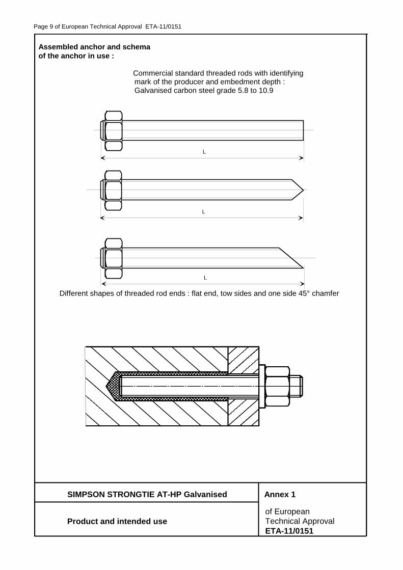
The SIMPSON STRONGTIE AT-HP galvanized in the sizes M8 to M20 is a bonded anchor (injection type) made of galvanised steel, which is placed into a drilled hole previously injected with a two components injection mortar using an applicator gun equipped with a special mixing nozzle. The threaded rod is inserted into the resin with a slow and slight twisting motion. The threaded rod can be used with a one side 45° chamfer, with a two sides 45° chamfer or with a flat tip end. The mortar cartridges are coaxial cartridges available in two different sizes as coaxial cartridges (280 ml and 345 ml) and two different sizes as side-by-side cartridges (380 ml and 825ml). The anchor is intended to be used with embedment depth from 8 diameters to 12 diameters. For the installed anchor see Figure given in Annex 1.
1.2. Intended use
The anchor is intended to be used for anchorages for which requirements for mechanical resistance and stability and safety in use in the sense of the Essential Requirements 1 and 4 of Council Directive 89/106/EEC shall be fulfilled and failure of anchorages made with these products would compromise the stability of the works, cause risk to human life and/or lead to considerable economic consequences. Safety in case of fire (Essential Requirement 2) is not covered in this ETA. The anchor is to be used only for anchorages subject to static or quasi-static loading in reinforced or unreinforced normal weight concrete of strength classes C 20/25 at least to C50/60 at most according to ENV 206-1: 2000. It may be anchored in non-cracked concrete only.
The anchor may only be used in concrete subject to dry internal conditions.
The anchor may be installed in dry or wet concrete (use category 1) for all diameters.
Installation Substrate
Dry concrete Wet concrete Flooded hole
All diameters Yes Yes No
All the diameters (i.e. from M8 to M20) may be used overhead.
The anchor may be used in the following temperature range : Temperature range : -40°C to +40°C (max short term temperature +40°C and
max long term temperature +24°C)
The provisions made in this European Technical Approval are based on an assumed intended working life of the anchor of 50 years. The indications given on the working life cannot be interpreted as a guarantee given by the producer, but are to be regarded only as a means for choosing the right products in relation to the expected economically reasonable working life of the works.
Page 4 of European Technical Approval ETA-11/0151
2 Characteristics of product and methods of verification
2.1. Characteristics of product
The anchor in the sizes of M8 to M20 and the mortar cartridges correspond to the drawings and provisions given in Annexes 1 and 2. The characteristic material values, dimensions and tolerances of the anchor not indicated in Annexes 3 and 4 shall correspond to the respective values laid down in the technical documentation
5 of this European Technical Approval. The
characteristic anchor values for the design of anchorages are given in Annexes 5 to 7.
Each mortar cartridge is marked with the identifying mark of the producer, the trade name, the charge code, storage life, curing and processing time. Commercial standard threaded rods can be used as metal part of the anchor system. If the threaded rods are supplied separately by another party than the approval holder, then it shall be ensured:
Mechanical properties according to EN ISO 898-1
Quality affirmation of the mechanical properties with an inspection document according to EN 10204
Marking of the threaded rod with the identifying mark of the producer of the rod and the envisage embedment depth.
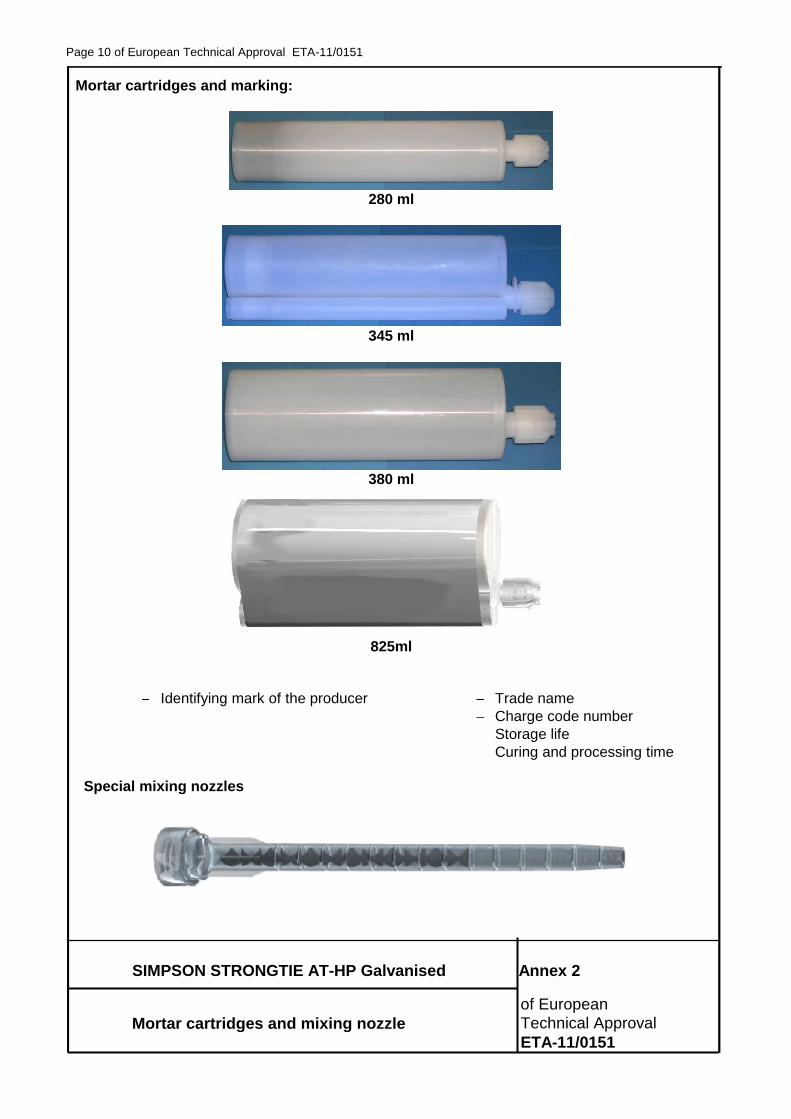
The two components of the injection mortar AT-HP could be delivered in unmixed condition in mortar cartridges of two different sizes as coaxial cartridges (280 ml, 345 ml) and two different sizes as side-by-side cartridges (380 ml, 825ml) as shown in Annex 2.
2.2. Methods of verification
The assessment of fitness of the anchor for the intended use in relation to the requirements for mechanical resistance and stability and safety in use in the sense of the Essential Requirements 1 and 4 has been made in accordance with the « Guideline for European Technical Approval of Metal Anchors for use in Concrete », Part 1 « Anchors in general » and Part 5 « Bonded anchors », on the basis of Option 8.
In addition to the specific clauses relating to dangerous substances contained in this European Technical Approval, there may be other requirements applicable to the products falling within its scope (e.g. transposed European legislation and national laws, regulations and administrative provisions). In order to meet the provisions of the UE Construction Products Directive, these requirements need also to be complied with, when and where they apply.
3 Evaluation of Conformity and CE marking
3.1. Attestation of conformity system
The system of attestation of conformity 2 (i) (referred to as system 1) according to Council Directive 89/106/EEC Annex III laid down by the European Commission provides:
a) tasks for the manufacturer:
1. factory production control, 2. further testing of samples taken at the factory by the manufacturer in accordance
with a prescribed test plan.
b) tasks for the approved body:
3. initial type-testing of the product, 4. initial inspection of factory and of factory production control, 5. continuous surveillance, assessment and approval of factory production control.
5 The technical documentation of this European Technical Approval is deposited at the Centre Scientifique
et Technique du Bâtiment and, as far as relevant for the tasks of the approved bodies involved in the attestation of conformity procedure, is handed over to the approved bodies.
Page 5 of European Technical Approval ETA-11/0151
3.2. Responsibilities
3.2.1. Tasks of the manufacturer, factory production control
The manufacturer has a factory production control system in the plant and exercises permanent internal control of production. All the elements, requirements and provisions adopted by the manufacturer are documented in a systematic manner in the form of written policies and procedures. This production control system ensures that the product is in conformity with the European Technical Approval.
The manufacturer shall only use raw materials supplied with the relevant inspection documents as laid down in the prescribed test plan
6. The incoming raw materials shall be subject to
controls and tests by the manufacturer before acceptance. Check of incoming materials such as resin and hardener shall include control of the inspection documents presented by suppliers (comparison with nominal values) by verifying the relevant material properties.
The manufactured components of the anchor shall be subjected to the following tests: Physical properties: resin (fill quantity, fill weight), hardener (fill quantity, fill weight).
Material properties: resin (composition, viscosity), hardener (composition, viscosity).
Visual control of the aspect of cartridges.
The frequency of controls and tests conducted during production is laid down in the prescribed test plan taking account of the automated manufacturing process of the anchor.
The results of factory production control are recorded and evaluated. The records include at least the following information:
designation of the product, basic material and components;
type of control or testing;
date of manufacture of the product and date of testing of the product or basic material and components;
result of control and testing and, if appropriate, comparison with requirements;
signature of person responsible for factory production control.
The records shall be presented to the inspection body during the continuous surveillance. On request, they shall be presented to the Centre Scientifique et Technique du Bâtiment.
Details of the extent, nature and frequency of testing and controls to be performed within the factory production control shall correspond to the prescribed test plan which is part of the technical documentation of this European Technical Approval.
3.2.2. Tasks of approved bodies
3.2.2.1. Initial type-testing of the product
For initial type-testing the results of the tests performed as part of the assessment for the European Technical Approval shall be used unless there are changes in the production line or plant. In such cases the necessary initial type-testing has to be agreed between the Centre Scientifique et Technique du Bâtiment and the approved bodies involved.
3.2.2.2. Initial inspection of factory and of factory production control
The approved body shall ascertain that, in accordance with the prescribed test plan, the factory and the factory production control are suitable to ensure continuous and orderly manufacturing of the anchor according to the specifications mentioned in 2.1. as well as to the Annexes to the European Technical Approval.
6 The prescribed test plan has been deposited at the Centre Scientifique et Technique du Bâtiment and is
only made available to the approved bodies involved in the conformity attestation procedure.
Page 6 of European Technical Approval ETA-11/0151
3.2.2.3. Continuous surveillance
The approved body shall visit the factory at least once a year for regular inspection. It has to be verified that the system of factory production control and the specified automated manufacturing process are maintained taking account of the prescribed test plan.
Continuous surveillance and assessment of factory production control have to be performed according to the prescribed test plan.
The results of product certification and continuous surveillance shall be made available on demand by the certification body or inspection body, respectively, to the Centre Scientifique et Technique du Bâtiment. In cases where the provisions of the European Technical Approval and the prescribed test plan are no longer fulfilled the conformity certificate shall be withdrawn.
3.3. CE-Marking
The CE marking shall be affixed on each packaging of anchors. The symbol « CE » shall be accompanied by the following information:
identification number of the certification body;
name or identifying mark of the producer and manufacturing plant;
the last two digits of the year in which the CE-marking was affixed;
number of the EC certificate of conformity;
number of the European Technical Approval;
use category (ETAG 001-1 Option 8);
size.
4 Assumptions under which the fitness of the product for the intended use was
favourably assessed
4.1. Manufacturing
The anchor is manufactured in accordance with the provisions of the European Technical Approval using the automated manufacturing process as identified during inspection of the plant by the Centre Scientifique et Technique du Bâtiment and the approved body and laid down in the technical documentation.
4.2. Installation
4.2.1. Design of anchorages
The fitness of the anchors for the intended use is given under the following conditions:
The anchorages are designed in accordance with the « Guideline for European Technical Approval of Metal Anchors for Use in Concrete », Annex C, Method A, for bonded anchors under the responsibility of an engineer experienced in anchorages and concrete work.
For the verifications given below according to annex C the following shall be observed :
- For the verification “concrete cone failure” (clause 5.2.2.4, Annex C of the ETAG, NRk,c shall be determined according to (1) and (2) : the smaller of the values according to (1) and (2) is decisive.
(1) NRk,c according to equation (5.2), Annex C of the ETAG where : N
0Rk,c according to Table 6a Annex 5
scr,N and ccr,N according to Table 6b Annex 6 ψucr,N = 1,0
Page 7 of European Technical Approval ETA-11/0151
In special cases according to clause 5.2.2.4 g, Annex C of the ETAG the method given there is valid. However the value N
0Rk,c shall be calculated according to the following equation :
N
0Rk,c = N
0Rk,c (Table 5) x (h’ef / hef)
(2) NRk,c according to equation (5.2), Annex C of the Guideline where : N
0Rk,c = 0,75 x 15,5 x hef
1,5 x fck,cube
0,5
scr,N = 3 hef and ccr,N = 1,5 hef ψucr,N = 1,0
- For the verification “splitting failure due to loading” (clause 5.2.2.6, Annex C of the ETAG), NRk,sp shall be determined according to (3).
(3) NRk,sp according to equation (5.3), Annex C of the ETAG where : N
0Rk,c according to Table 6a Annex 5
scr,sp and ccr,sp according to Table 6b Annex 6 ψucr,N= 1,0 and ψh,sp = 1,0
- For the verification “concrete pryout failure” (clause 5.2.3.3, Annex C of the ETAG), NRk,c for equation (5.6), Annex C of the ETAG shall be determined according to (1).
Verifiable calculation notes and drawings are prepared taking account of the loads to be anchored.
The position of the anchor is indicated on the design drawings (e.g. position of the anchor relative to reinforcement or to support, etc.).
4.2.2. Installation of anchors
The fitness for use of the anchor can only be assumed if the anchor is installed as follows:
anchor installation carried out by appropriately qualified personnel and under the supervision of the person responsible for technical matters on the site;
use of the anchor only as supplied by the manufacturer without exchanging the components of an anchor;
anchor installation in accordance with the manufacturer’s specifications and drawings using the tools indicated in the technical documentation of this European Technical Approval;
checks before placing the anchor to ensure that the strength class of the concrete in which the anchor is to be placed is in the range;
check of concrete being well compacted, e.g. without significant voids;
keeping the effective anchorage depth;
keeping of the edge distance and spacing to the specified values without minus tolerances;
positioning of the drill holes without damaging the reinforcement;
in case of aborted drill hole: the drill hole shall be filled with mortar;
clearing the hole of drilling dust : the hole shall be cleaned by at least two blowing operations, by at least two brushing operations followed again by at least two blowing, and again two brushing and two blowing operations; before brushing cleaning the brush and checking whether the brush diameter according to Annex 3 Table 2 is sufficient;
anchor installation ensuring the specified embedment depth, that is the appropriate depth marking of the anchor not exceeding the concrete surface;
mortar injection by using the equipment including the special mixing nozzle shown in Annex 2; discarding the first swings of mortar of each new cartridge until an homogeneous colour is achieved; taking from the manufacturer instruction the admissible processing time (open time) of a cartridge as a function of the ambient temperature of the concrete; filling the drill hole uniformly from the drill hole bottom, in order to avoid entrapment of air; removing the special mixing nozzle slowly bit by bit during pressing-out; filling the drill hole with a quantity of the injection mortar corresponding to ½ of the drill hole; inserting immediately the anchor rod or threaded rod, slowly and with a slight twisting motion, removing excess of injection
Page 8 of European Technical Approval ETA-11/0151
mortar around the rod; observing the curing time according to Annex 2 table 2 until the rod may be loaded; during curing of the injection mortar the temperature of the concrete must not fall below 0°C;
application of the torque moment given in Annex 4 Table 3 using a calibrated torque wrench.
4.2.3. Responsibility of the manufacturer
It is the manufacturer’s responsibility to ensure that the information on the specific conditions according to 1 and 2 including Annexes referred to in 4.2.1. and 4.2.2. is given to those who are concerned. This information may be made by reproduction of the respective parts of the European Technical Approval. In addition all installation data shall be shown clearly on the package and/or on an enclosed instruction sheet, preferably using illustration(s).
The minimum data required are:
drill bit diameter,
thread diameter,
maximum thickness of the fixture,
minimum installation depth,
required torque moment,
admissible service temperature range,
curing time of the bonding material depending on the installation temperature,
information on the installation procedure, including cleaning of the hole, preferably by means of an illustration,
reference to any special installation equipment needed,
identification of the manufacturing batch.
All data shall be presented in a clear and explicit form.
5 Recommendations concerning packaging, transport and storage.
The mortar cartridges shall be protected against sun radiation and shall be stored according to the manufacturer’s installation instructions in dry conditions at temperatures of at least 5°C to not more than +35°C.
Mortar cartridges with expired shelf life must no longer be used.
The original French version is signed by
Le Directeur Technique
C. BALOCHE
Page 9 of European Technical Approval ETA-11/0151
SIMPSON STRONGTIE AT-HP Galvanised Annex 1
of European
Product and intended use Technical Approval
ETA-11/0151
Assembled anchor and schema
of the anchor in use : Commercial standard threaded rods with identifying mark of the producer and embedment depth : Galvanised carbon steel grade 5.8 to 10.9
L
L
L
Different shapes of threaded rod ends : flat end, tow sides and one side 45° chamfer
Page 10 of European Technical Approval ETA-11/0151
SIMPSON STRONGTIE AT-HP Galvanised Annex 2
of European
Mortar cartridges and mixing nozzle Technical Approval
ETA-11/0151
Mortar cartridges and marking:
280 ml
345 ml
380 ml
825ml
Identifying mark of the producer
Trade name
Charge code number
Storage life
Curing and processing time
Special mixing nozzles
Page 11 of European Technical Approval ETA-11/0151
SIMPSON STRONGTIE AT-HP Galvanised Annex 3
of European
Materials and cleaning method Technical Approval
ETA-11/0151
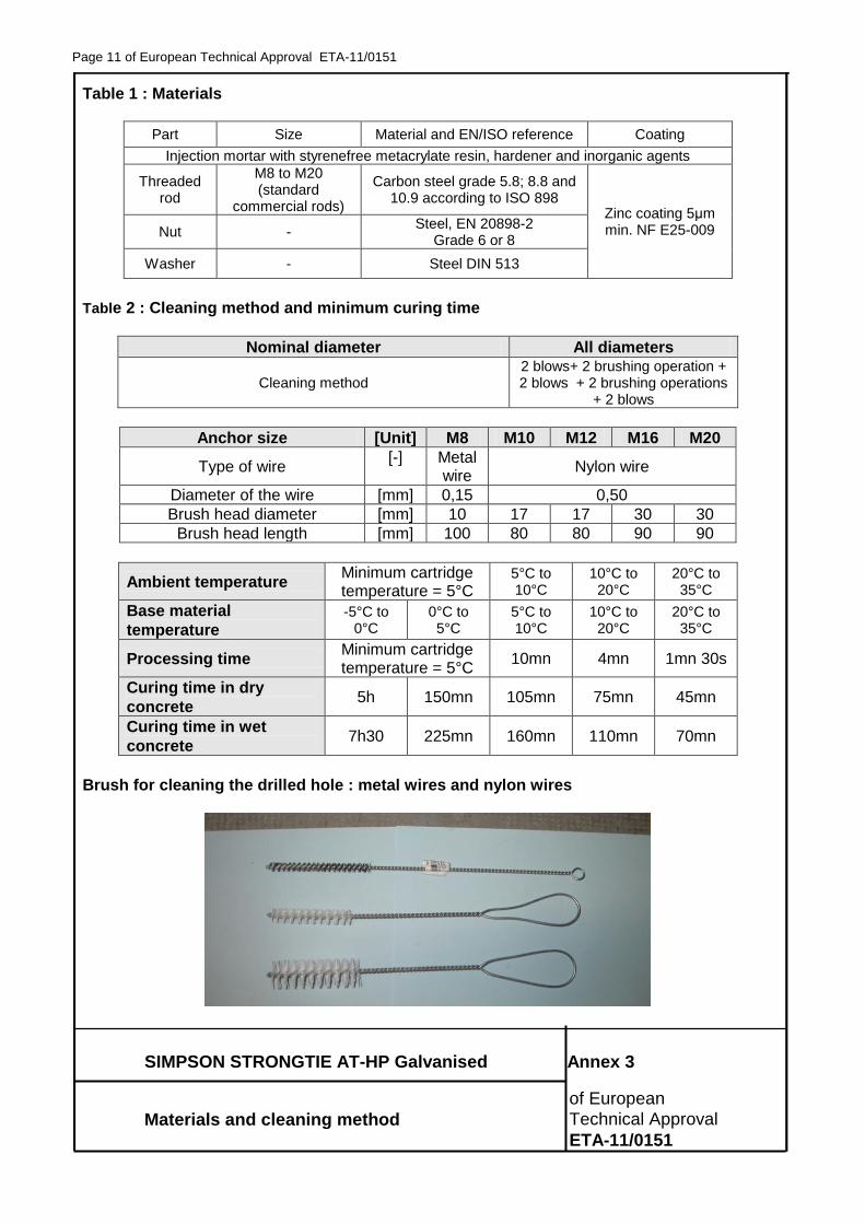
Table 1 : Materials
Part Size Material and EN/ISO reference Coating
Injection mortar with styrenefree metacrylate resin, hardener and inorganic agents
Threaded rod
M8 to M20 (standard
commercial rods)
Carbon steel grade 5.8; 8.8 and 10.9 according to ISO 898
Zinc coating 5μm min. NF E25-009 Nut -
Steel, EN 20898-2 Grade 6 or 8
Washer - Steel DIN 513
Table 2 : Cleaning method and minimum curing time
Nominal diameter All diameters
Cleaning method 2 blows+ 2 brushing operation + 2 blows + 2 brushing operations
+ 2 blows
Anchor size [Unit] M8 M10 M12 M16 M20
Type of wire [-] Metal
wire Nylon wire
Diameter of the wire [mm] 0,15 0,50
Brush head diameter [mm] 10 17 17 30 30
Brush head length [mm] 100 80 80 90 90
Ambient temperature Minimum cartridge temperature = 5°C
5°C to 10°C
10°C to 20°C
20°C to 35°C
Base material
temperature -5°C to
0°C
0°C to 5°C
5°C to 10°C
10°C to 20°C
20°C to 35°C
Processing time Minimum cartridge temperature = 5°C
10mn 4mn 1mn 30s
Curing time in dry
concrete 5h 150mn 105mn 75mn 45mn
Curing time in wet
concrete 7h30 225mn 160mn 110mn 70mn
Brush for cleaning the drilled hole : metal wires and nylon wires
Page 12 of European Technical Approval ETA-11/0151
SIMPSON STRONGTIE AT-HP Galvanised Annex 4
of European
Installation data Technical Approval
ETA-11/0151
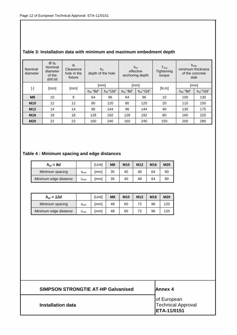
Table 3: Installation data with minimum and maximum embedment depth
Nominal diameter
Ø d0 Nominal diameter
of the drill bit
df Clearance hole in the
fixture
h0 depth of the hole
hef effective
anchoring depth
Tinst Tightening
torque
hmin minimum thickness
of the concrete slab
[-] [mm] [mm] [mm] [mm]
[N.m] [mm]
hef “8d” hef”12d” hef “8d” hef”12d” hef “8d” hef”12d”
M8 10 9 64 96 64 96 10 100 130
M10 12 12 80 120 80 120 20 110 150
M12 14 14 96 144 96 144 40 130 175
M16 18 18 128 192 128 192 80 160 225
M20 22 22 160 240 160 240 150 200 280
Table 4 : Minimum spacing and edge distances
hef = 8d [Unit] M8 M10 M12 M16 M20
Minimum spacing smin [mm] 35 40 48 64 80
Minimum edge distance cmin [mm] 35 40 48 64 80
hef = 12d [Unit] M8 M10 M12 M16 M20
Minimum spacing smin [mm] 48 60 72 96 120
Minimum edge distance cmin [mm] 48 60 72 96 120
Page 13 of European Technical Approval ETA-11/0151
SIMPSON STRONGTIE AT-HP Galvanised Annex 5
Characteristic resistance of European
under tension loads – design method A Technical Approval
ETA-11/0151
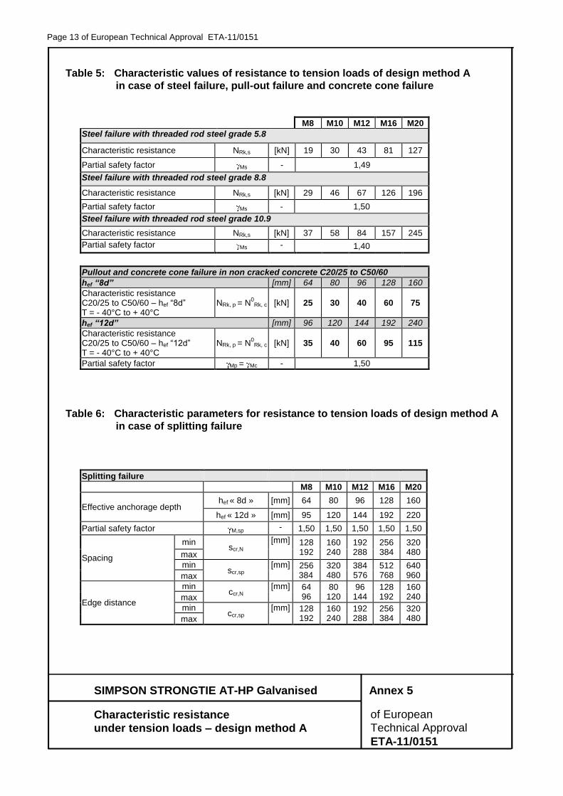
Table 5: Characteristic values of resistance to tension loads of design method A
in case of steel failure, pull-out failure and concrete cone failure
M8 M10 M12 M16 M20
Steel failure with threaded rod steel grade 5.8
Characteristic resistance NRk,s [kN] 19 30 43 81 127
Partial safety factor Ms - 1,49
Steel failure with threaded rod steel grade 8.8
Characteristic resistance NRk,s [kN] 29 46 67 126 196
Partial safety factor Ms - 1,50
Steel failure with threaded rod steel grade 10.9
Characteristic resistance NRk,s [kN] 37 58 84 157 245
Partial safety factor Ms - 1,40
Pullout and concrete cone failure in non cracked concrete C20/25 to C50/60
hef “8d” [mm] 64 80 96 128 160
Characteristic resistance C20/25 to C50/60 – hef “8d” T = - 40°C to + 40°C
NRk, p = N0
Rk, c [kN] 25 30 40 60 75
hef “12d” [mm] 96 120 144 192 240
Characteristic resistance C20/25 to C50/60 – hef “12d” T = - 40°C to + 40°C
NRk, p = N0
Rk, c [kN] 35 40 60 95 115
Partial safety factor Mp = Mc - 1,50
Table 6: Characteristic parameters for resistance to tension loads of design method A
in case of splitting failure
Splitting failure
M8 M10 M12 M16 M20
Effective anchorage depth hef « 8d » [mm] 64 80 96 128 160
hef « 12d » [mm] 95 120 144 192 220
Partial safety factor M,sp - 1,50 1,50 1,50 1,50 1,50
Spacing
min scr,N
[mm] 128 192
160 240
192 288
256 384
320 480 max
min scr,sp
[mm] 256 384
320 480
384 576
512 768
640 960 max
Edge distance
min ccr,N
[mm] 64 96
80 120
96 144
128 192
160 240 max
min ccr,sp
[mm] 128 192
160 240
192 288
256 384
320 480 max
Page 14 of European Technical Approval ETA-11/0151
SIMPSON STRONGTIE AT-HP Galvanised Annex 6
Characteristic resistance of European
under shear loads – design method A Technical Approval
ETA-11/0151
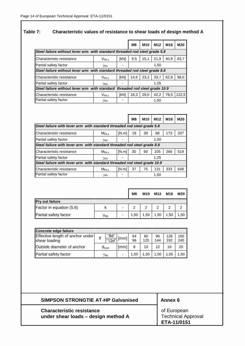
Table 7: Characteristic values of resistance to shear loads of design method A
M8 M10 M12 M16 M20
Steel failure without lever arm with standard threaded rod steel grade 5.8
Characteristic resistance VRk,s [kN] 9,5 15,1 21,9 40,8 63,7
Partial safety factor Ms - 1,50
Steel failure without lever arm with standard threaded rod steel grade 8.8
Characteristic resistance VRk,s [kN] 14,6 23,2 33,7 62,8 98,0
Partial safety factor Ms - 1,25
Steel failure without lever arm with standard threaded rod steel grade 10.9
Characteristic resistance VRk,s [kN] 18,3 29,0 42,2 78,5 122,5
Partial safety factor Ms - 1,50
M8 M10 M12 M16 M20
Steel failure with lever arm with standard threaded rod steel grade 5.8
Characteristic resistance MRk,s [N.m] 19 39 68 173 337
Partial safety factor Ms - 1,50
Steel failure with lever arm with standard threaded rod steel grade 8.8
Characteristic resistance MRk,s [N.m] 30 60 105 266 519
Partial safety factor Ms - 1,25
Steel failure with lever arm with standard threaded rod steel grade 10.9
Characteristic resistance MRk,s [N.m] 37 75 131 333 649
Partial safety factor Ms - 1,50
M8 M10 M12 M16 M20
Pry out failure
Factor in equation (5.6) k - 2 2 2 2 2
Partial safety factor Mp - 1,50 1,50 1,50 1,50 1,50
Concrete edge failure
Effective length of anchor under shear loading
lf “8d”
[mm] 64 96
80 120
96 144
128 192
160 240 “12d”
Outside diameter of anchor dnom [mm] 8 10 12 16 20
Partial safety factor Mc - 1,50 1,50 1,50 1,50 1,50
Page 15 of European Technical Approval ETA-11/0151
SIMPSON STRONGTIE AT-HP Galvanised Annex 7
Characteristic displacements of European
under tension and shear loads Technical Approval
ETA-11/0151
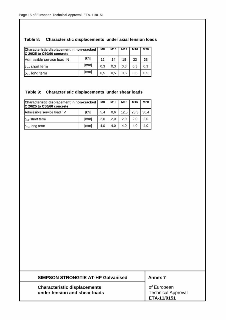
Table 8: Characteristic displacements under axial tension loads
Characteristic displacement in non-cracked
C 20/25 to C50/60 concrete
M8 M10 M12 M16 M20
Admissible service load :N [kN] 12 14 18 33 38
N0 short term [mm] 0,3 0,3 0,3 0,3 0,3
N long term [mm] 0,5 0,5 0,5 0,5 0,5
Table 9: Characteristic displacements under shear loads
Characteristic displacement in non-cracked
C 20/25 to C50/60 concrete
M8 M10 M12 M16 M20
Admissible service load : V [kN] 5,4 8,6 12,5 23,3 36,4
N0 short term [mm] 2,0 2,0 2,0 2,0 2,0
N long term [mm] 4,0 4,0 4,0 4,0 4,0