Embed Size (px)
Citation preview
Centre Scientifique et Technique du Bâtiment 84 avenue Jean Jaurès Champs sur Marne F-77447 Marne-la-Vallée Cedex 2 Tél. : (33) 01 64 68 82 82 Fax : (33) 01 60 05 70 37
Autorisé etnotifié conformément à
l’article 10 de la directive89/106/EEC du Conseil, du
21 décembre 1988, relative aurapprochement des dispositions
législatives, réglementaireset administratives des Etats
membres concernantles produits deconstruction.
MEMBRE DE L’EOTA
European Technical Approval ETA-11/0390 (English language translation, the original version is in French language)
Nom commercial :
Trade name: Injection System Hilti HIT-CT 1 for rebar connection
Titulaire :
Holder of approval: Hilti Corporation
Feldkircherstrasse 100 FL-9494 Schaan Principality of Liechtenstein
Type générique et utilisation prévue du produit de construction :
Scellement d’armatures rapportées, diamètres 8 à 25mm, avec Système d’injection Hilti HIT-CT 1
Generic type and use of construction product:
Post installed rebar connections diameter 8 to 25 mm made with Hilti HIT-CT 1 injection mortar.
Validité du : au : Validity from / to:
27/08/2012 31/10/2016
Usine de fabrication :
Manufacturing plant: Hilti Plants
Le présent Agrément technique européen contient :
This European Technical Approval contains:
30 pages incluant 20 annexes faisant partie intégrante du document. 30 pages including 20 annexes which form an integral part of the document.
Cet Agrément Technique Européen remplace l’Agrément ETA-11/0390 valide du 31/10/2011 au 31/10/2016
This European Technical Approval replaces ETA-11/0390 with validity from 31/10/2011 to 31/10/2016
Organisation pour l’Agrément Technique Européen
European Organisation for Technical Approvals

Page 2 of European technical approval ETA–11/0390, issued on 27.08.2012 English translation prepared by CSTB
I LEGAL BASES AND GENERAL CONDITIONS
1. This European Technical Approval is issued by the Centre Scientifique et Technique du Bâtiment in accordance with:
- Council Directive 89/106/EEC of 21 December 1988 on the approximation of laws, regulations
and administrative provisions of Member States relating to construction products1, modified by the
Council Directive 93/68/EEC of 22 July 19932 and Regulation (EC) N° 1882/2003 of the European
Parliament and of the Council3 ;
- Décret n° 92-647 du 8 juillet 19924 concernant l’aptitude à l’usage des produits de construction;
Common Procedural Rules for Requesting, Preparing and the Granting of European Technical
Approvals set out in the Annex of Commission Decision 94/23/EC5;
- Guideline for European Technical Approval of « Metal Anchors for use in Concrete » ETAG 001, edition 1997, Part 1 « Anchors in general », Part 5 « Bonded anchors» and Technical Report for Post Installed Rebar Connections TR23.
2. The Centre Scientifique et Technique du Bâtiment is authorised to check whether the provisions of
this European Technical Approval are met. Checking may take place in the manufacturing plant (for example concerning the fulfilment of assumptions made in this European Technical Approval with regard to manufacturing). Nevertheless, the responsibility for the conformity of the products with the European Technical Approval and for their fitness for the intended use remains with the holder of the European Technical Approval.
3. This European Technical Approval is not to be transferred to manufacturers or agents of manufacturer other than those indicated on page 1; or manufacturing plants other than those indicated on page 1 of this European Technical Approval.
4. This European Technical Approval may be withdrawn by the Centre Scientifique et Technique du Bâtiment pursuant to Article 5 (1) of the Council Directive 89/106/EEC.
5. Reproduction of this European Technical Approval including transmission by electronic means shall be in full. However, partial reproduction can be made with the written consent of the Centre Scientifique et Technique du Bâtiment. In this case partial reproduction has to be designated as such. Texts and drawings of advertising brochures shall not contradict or misuse the European Technical Approval.
6. The European Technical Approval is issued by the approval body in its official language. This version corresponds to the version circulated within EOTA. Translations into other languages have to be designated as such.
1 Official Journal of the European Communities n° L 40, 11.2.1989, p. 12 2 Official Journal of the European Communities n° L 220, 30.8.1993, p. 1 3 Official Journal of the European Union L 284, 31 October 2003, p. 25 4 Journal officiel de la République française du 14 juillet 1992 5 Official Journal of the European Communities n° L 17, 20.1.1994, p. 34
Page 3 of European technical approval ETA–11/0390, issued on 27.08.2012 English translation prepared by CSTB
II SPECIFIC CONDITIONS OF THE EUROPEAN TECHNICAL APPROVAL
1 Definition of product and intended use
1.1 Definition of product
The Hilti HIT-CT 1 is used for the connection, by anchoring or overlap joint, of reinforcing bars (rebars) in existing structures made of ordinary non-carbonated concrete C12/15 to C50/60. The design of the post-installed rebar connections is done in accordance with EN 1992-1-1 October 2005 (EN 1992-1-1).
Covered are rebar anchoring systems consisting of Hilti HIT-CT 1 bonding material and the Hilti tension anchor HZA-R sizes M12, M16 and M20 or an embedded straight deformed reinforcing bar diameter, d, from 8 to 25 mm with properties according to Annex C of EN 1992-1-1 and EN 10080. The classes B and C of the rebar are recommended.
1.2 Intended use
The ETA covers applications in non-carbonated concrete C 12/15 to C 50/60 (EN 206-1) only, which are also allowed with straight deformed cast-in bars according to EN 1992-1-1, e.g. those in the following applications:
overlapping joints with existing reinforcement in a building component, Figure 1 and 2 in annex 2.
anchoring of the reinforcement at an end support/bearing of a slab or a beam designed as simply supported as well as its reinforcement for restraint forces, Figure 3 in annex 2.
anchoring of reinforcement of building components stressed primarily in compression, Figure 4 in annex 2.
anchoring of reinforcement to cover the line of acting tensile force, Figure 5 in annex 2.
Rebar connections with the Hilti HZA-R may be used for the transmission of tensile forces in the direction of the bar axis only. The transmission of shear forces has to be ensured by appropriate measures, Figure 6, 7 and 8 in annex 3.
The Hilti HIT-CT 1anchoring systems can be used with the following limitations:
The rebars can be placed in holes made with hammer drilling, hollow drilling Hilti TE-CD/TE-YD or compress air drilling only
The rebars may be used in the following temperature range : -40°C to +80°C (max short term temperature +80°C and max long term temperature +50°C)
According to EN 206-1 the allowable chloride content in concrete is limited to 0.40% (Cl 0,40) related to cement content.
The rebars may be installed in dry or wet concrete, but must not be installed in flooded holes. The rebar connections may be used for predominantly static loads.
The fire resistance of post-installed rebar connections is not covered by this ETA.
Fatigue, dynamic or seismic loading of post-installed rebar connections are not covered by this ETA.
The provisions made in this European Technical Approval are based on an assumed intended working life of the rebar connections of 50 years. The indications given on the working life cannot be interpreted as a guarantee given by the producer, but are to be regarded only as a means for choosing the right products in relation to the expected economically reasonable working life of the works.

Page 4 of European technical approval ETA–11/0390, issued on 27.08.2012 English translation prepared by CSTB
2 Characteristics of product and methods of verification
2.1 Characteristics of product
The Hilti HIT-CT 1 injection adhesive corresponds to the drawings and provisions given in annexes 1 to 7.
The Hilti HIT-CT 1 injection adhesive is a two components system. The two components of the injection mortar are delivered in unmixed condition in foil packs of sizes 330ml or 500ml according to annex 1. Each foil pack is marked with the identifying mark “Hilti HIT-CT 1” with the production date and expiration date.
2.2 Methods of verification
The assessment of fitness of the rebar connection for the intended use in relation to the requirements for mechanical resistance and stability and safety in use in the sense of the Essential Requirements 1 and 4 has been made in accordance with the « Guideline for European Technical Approval of Metal Anchors for use in Concrete », Part 1 « Anchors in general », Part 5 « Bonded anchors » and Technical Report n° 023 “Assessment of post installed rebar connections”.
In addition to the specific clauses relating to dangerous substances contained in this European Technical Approval, there may be other requirements applicable to the products falling within its scope (e.g. transposed European legislation and national laws, regulations and administrative provisions). In order to meet the provisions of the UE Construction Products Directive, these requirements need also to be complied with, when and where they apply.
3 Evaluation of Conformity and CE marking
3.1 Attestation of conformity system
The system of attestation of conformity 2 (i) (referred to as system 1) according to Council Directive 89/106/EEC Annex III laid down by the European Commission provides:
a) tasks for the manufacturer:
1. factory production control, 2. further testing of samples taken at the factory by the manufacturer in accordance with a prescribed test plan.
b) tasks for the approved body:
3. initial type-testing of the product, 4. initial inspection of factory and of factory production control, 5. continuous surveillance, assessment and approval of factory production control.
3.2 Responsibilities
3.2.1 Tasks of the manufacturer, factory production control
The manufacturer has a factory production control system in the plant and exercises permanent internal control of production. All the elements, requirements and provisions adopted by the manufacturer are documented in a systematic manner in the form of written policies and procedures. This production control system ensures that the product is in conformity with the European Technical Approval.
The manufacturer shall only use raw materials supplied with the relevant inspection documents as
laid down in the prescribed test plan1. The incoming raw materials shall be subject to controls and tests by the manufacturer before acceptance. Check of incoming materials shall include control of the inspection documents presented by suppliers.
1 The prescribed test plan has been deposited at the Centre Scientifique et Technique du Bâtiment and is only made available
to the approved bodies involved in the conformity attestation procedure.

Page 5 of European technical approval ETA–11/0390, issued on 27.08.2012 English translation prepared by CSTB
The frequency of controls and tests conducted during production is laid down in the prescribed test plan taking account of the automated manufacturing process of the product.
The results of factory production control are recorded and evaluated. The records include at least the following information:
designation of the product, basic material and components;
type of control or testing;
date of manufacture of the product and date of testing of the product or basic material and components;
result of control and testing and, if appropriate, comparison with requirements;
signature of person responsible for factory production control.
The records shall be presented to the inspection body during the continuous surveillance. On request, they shall be presented to the Centre Scientifique et Technique du Bâtiment.
Details of the extent, nature and frequency of testing and controls to be performed within the factory production control shall correspond to the prescribed test plan which is part of the technical documentation of this European Technical Approval.
3.2.2 Tasks of approved bodies
3.2.2.1 Initial type-testing of the product
For initial type-testing the results of the tests performed as part of the assessment for the European Technical Approval shall be used unless there are changes in the production line or plant. In such cases the necessary initial type-testing has to be agreed between the Centre Scientifique et Technique du Bâtiment and the approved bodies involved.
3.2.2.2 Initial inspection of factory and of factory production control
The approved body shall ascertain that, in accordance with the prescribed test plan, the factory and the factory production control are suitable to ensure continuous and orderly manufacturing of the anchor according to the specifications mentioned in 2.1. as well as to the Annexes to the European Technical Approval.
3.2.2.3 Continuous surveillance
The approved body shall visit the factory at least once a year for regular inspection. It has to be verified that the system of factory production control and the specified automated manufacturing process are maintained taking account of the prescribed test plan.
Continuous surveillance and assessment of factory production control have to be performed according to the prescribed test plan.
The results of product certification and continuous surveillance shall be made available on demand by the certification body or inspection body, respectively, to the Centre Scientifique et Technique du Bâtiment. In cases where the provisions of the European Technical Approval and the prescribed test plan are no longer fulfilled the conformity certificate shall be withdrawn.
3.3 CE-Marking
The CE marking shall be affixed on each packaging of anchors. The symbol « CE » shall be accompanied by the following information:
name or identifying mark of the producer and manufacturing plant;
the last two digits of the year in which the CE-marking was affixed;
number of the EC certificate of conformity;
number of the European Technical Approval;
Page 6 of European technical approval ETA–11/0390, issued on 27.08.2012 English translation prepared by CSTB
4 Assumptions under which the fitness of the product for the intended use was favourably assessed
4.1 Manufacturing
The resin and the Hilti tension anchor HZA-R are manufactured in accordance with the provisions of the European Technical Approval using the automated manufacturing process as identified during inspection of the plant by the Centre Scientifique et Technique du Bâtiment and the approved body and laid down in the technical documentation. Changes to the product or production process, which could result in this deposited data/information being incorrect, should be notified to the Centre Scientifique et Technique du Bâtiment before the changes are introduced. The Centre Scientifique et Technique du Bâtiment will decide whether or not such changes affect the approval and consequently the validity of the CE marking on the basis of the approval and if so whether further assessment or alterations to the approval shall be necessary.
4.2 Drafting
Rebar connection must be designed in keeping with good engineering practice. Allowing for the loads to be anchored, design calculations and design drawings must be produced which can be checked. At least the following must be given in the design drawings:
Concrete strength.
Diameter, drilling technique, concrete cover, spacing and anchorage depth of the rebars.
Dimension for the depth of adhesive (dispensing amount to be marked on the mixer extension as per annex 14),
Use of a guide device (drilling aid) for the drilling holes close to edges (if necessary)
Kind of preparation of the joint between building component being connected.
4.3 Rebar connection design as per EN 1992-1-1
4.3.1 General points
The actual position of the reinforcement in the existing building component must be determined on the basis of the construction documentation and allowed for when drafting.
The transfer of internal section forces in the joint must be verified in accordance to EN 1992-1-1 when a new building component is being connected. The transfer of shear forces between new and old concrete shall be designed according to EN 1992-1-1. The joints for concreting must be roughened to at least such an extent that aggregate protrude.
The design of rebar connections and determination of the internal section forces to be transferred in the construction joint shall be in keeping with the EN 1992-1-1.
Hilti tension anchor HZA-R according to annexes 6 and 7 shall be designed for the welded-on reinforcement steel BSt 500S. The length of the bonded-in smooth shaft made of stainless steel may not be accounted as anchorage.
Verification of immediate local force transfer to the concrete has been provided.
Verification of the transfer of the loads to be anchored to the building component must be provided.
The spacing between post installed rebars - respectively Hilti tension anchor HZA-R shall be greater
than the maximum of 5ds and 50mm (according to Annex 5 - respectively Annex 7)
Page 7 of European technical approval ETA–11/0390, issued on 27.08.2012 English translation prepared by CSTB
4.3.2 Determination of anchorage depth.
4.3.2.1 General points
The design anchorage length lbd must be determined according to EN 1992-1-1, section 8.4.3.
The anchorage depths and overlap lengths must not be less than the minimum values given in annex 8. The maximum permissible anchorage depth is given in annex 8.
4.3.2.2 Calculation of the basic anchorage length lb,rqd
The basic anchorage length lb,rqd, for anchoring the force As.fyd in the rebar assuming constant bond stress equal to fbd follows from:
lb,rqd = (/4).(sd/fbd)
where : = diameter of the rebar
sd = calculated stress in the rebar under the design action
fbd = design value of the bond strength according to table 5 in annex 8
fbd = 2.25 1 2 fctd (according to EN 1992-1-1)
with fctd = ct fctk,0.05 / c
ct = 1 and c = 1.5
1 coefficient relative to the quality of the bond condition and position of the rebar during concreting
1 = 1,0 (“good” bond conditions)
1 = 0,7 (all other conditions)
2 = 1,0 (for 25mm)
4.3.2.3 Calculation of the minimum anchorage length lb,min
Anchoring rebar
In the case of anchoring rebar, the minimum anchorage length lb,min must be determined as follow:
lb,min = crack x Max (0,3 lb,rqd; 10 ; 100mm) under tension
lb,min = crack x Max (0,6 lb,rqd; 10 ; 100mm) under compression
Overlap joint
In the case of overlap joint, the minimum anchorage length l0,min must be determined as follow:
l0,min = crack x Max (0,3.6.lb,rqd; 15 ; 200mm)
where 6= (1/25)0.5≤ 1.5 1 is the percentage of reinforcement lapped within 0.65 l0 from the centre of the length considered.
Concrete class crack
C20/25 1.0
C25/35 1.2
C30/37 to C50/60 1.4
Page 8 of European technical approval ETA–11/0390, issued on 27.08.2012 English translation prepared by CSTB
4.3.2.4 Calculation of the design anchorage length lbd
Anchoring rebar
In the case of anchoring rebar, the design anchorage length lbd must be determined as follow:
lbd = 1 2 3 4 5 lb,rqd ≥ lb,min
where 1, 2, 3, 4, 5 determined according to EN 1992-1-1.Table 8.2.
Overlap joint
In the case of overlap joint, the design anchorage length lbd must be determined as follow:
l0 = 1 2 3 4 5 6 lb,rqd ≥ l0,min
Where 1, 2, 3, 4, 5, 6 determined according to, EN 1992-1-1.Table 8.2 and 8.3
1 Influence of the shape of the rebar 1 = 1 for straight rebar
2 Influence of the concrete cover 0.7 ≤ 2 ≤ 1.0 calculated according to EN 1992-1-1 Table 8.2
3 Influence of the confinement by transverse reinforcement not welded to main reinforcement
3 = 1 because no transverse reinforcement
4 Influence of the confinement by welded transverse reinforcement
4 = 1 because no transverse reinforcement
5 Influence of the confinement by transverse pressure
0.7 ≤ 5 ≤ 1.0
6 Influence of the overlapping length 1.0 ≤ 6 ≤ 1.5
Nota: Examples of calculations are published in annexes 18 and 19 for concrete C20/25. Other values can be calculated by using the above formulas.
4.3.2.5 Embedment depth for overlap joints with Hilti tension anchor HZA-R
The effective embedment depth is the same as the lap length lv = l0 (see Annex 7, Figure 12). The total embedment depth le.ges shall be determined as follows (see Annex 7, Figure 12):
le.ges ≥ l0 + le
with: l0 = required lap length acc. to Section 4.3.2 and to EN 1992-1-1 le = length of the smooth shaft see also Annex 7, le > c1
If the clear distance between overlapping rods exceeds 4ds, the overlap length shall be increased by
the difference between the actual clear distance and 4ds.
4.3.2.6 Transverse reinforcement
The transverse reinforcement required in the zone of the rebar or of the tension anchor HZA-R connection must fulfil the requirement of EN 1992-1-1, section 8.7.4.
4.3.2.7 Connection joint
In case of a connection being made between new and existing concrete where the surface layer of the existing concrete is carbonated, the layer should be removed in the area of the new reinforcing bar (with a diameter ds + 60mm) prior to the installation of the new bar. The foregoing may be neglected if building components are new and not carbonated.
4.3.2.8 Additional provisions
The concrete cover required for bonded-in rebars or tension anchor HZA-R is shown in Table 3 of Annex 8 in relation to the drilling method and the hole tolerance. Furthermore the minimum concrete cover given in EN 1992-1-1, Section 4.4.1.2 shall be observed.
Page 9 of European technical approval ETA–11/0390, issued on 27.08.2012 English translation prepared by CSTB
4.4 Installation
The fitness for use of the rebar connection can only be assumed if the rebar is installed as follows:
The installation of the post installed rebars respectively HZA-R shall be carried out according to the manufacturer’s installation instructions and this European technical approval, annexes 1 to 19;
The installation of post-installed rebars respectively HZA-R shall be done only by suitable trained installer and under supervision on site. The conditions under which an installer may be considered as suitable trained and the conditions for supervision on site are up to the Member States in which the installation is done.
Use of the system only as supplied by the manufacturer without exchanging the components of an system;
Checks before placing the rebar to ensure that the strength class of the concrete in which the rebar is to be placed is in the range;
The surface of the joint between new and existing concrete should be prepared (roughing, keying, according to the envisaged intended use according to EN 1992-1-1;
Check of concrete being well compacted, e.g. without significant voids;
Keeping the anchorage depth as specified in the design drawings;
Keeping of the concrete cover and spacing as specified in the design drawings;
The drilling and cleaning of the hole and the installation shall be performed only with the equipment as specified by the manufacturer given in annexes 9 to 17. It shall be ensured that this equipment is available on site and is used;
Positioning of the drill holes without damaging the reinforcement;
In case of aborted drill hole: the drill hole shall be filled with mortar;
The post installed rebar connection must not be installed in flooded holes;
Rebar installation ensuring the specified embedment depth, that is the appropriate depth marking of the rebar not exceeding the concrete surface;
4.5 Responsibility of the manufacturer
It is the manufacturer’s responsibility to ensure that the information on the specific conditions according to 1 and 2 including Annexes referred to in § 4.3. is given to those who are concerned. This information may be made by reproduction of the respective parts of the European Technical Approval. In addition all installation data shall be shown clearly on the package and/or on an enclosed instruction sheet, preferably using illustration(s).
The minimum data required are:
drill bit diameter,
rebar diameter,
admissible service temperature range
hole depth,
minimum effective anchorage depth,
information on the installation procedure, including cleaning of the hole with the cleaning equipments, preferably by means of an illustration,
material and property class of metal parts acc. to Annex 4 and Tables 1 and 2 of Annex 6,
anchor component installation temperature,
ambient temperature of the concrete during installation of the anchor,
admissible processing time (open time) of the mortar,
curing time until the anchor may be loaded as a function of the ambient temperature in the concrete during installation,
maximum torque moment, where applicable (HZA-R),
reference to any installation tool needed,
identification of the manufacturing batch,
All data shall be presented in a clear and explicit form.
Page 10 of European technical approval ETA–11/0390, issued on 27.08.2012 English translation prepared by CSTB
5 Recommendations concerning packaging, transport and storage.
Each cartridge of resin is marked with the identifying mark of the producer, the trade name, the charge code, storage life, curing and processing time.
The cartridges of resin shall be protected against sun radiation and shall be stored according to the manufacturer’s installation instructions in dry conditions at temperatures of at least +5°C to not more than +25°C.
Mortar cartridges with expired shelf life must no longer be used.
The original French version is signed by
Le Directeur Technique C. BALOCHE
Page 11 of European Technical Approval ETA-11/0390, issued on 27.08.2012 English translation prepared by CSTB
of the European Technical Approval
ETA - 11/0390
Injection System Hilti HIT-CT 1 for rebar connection
Product description and intended use
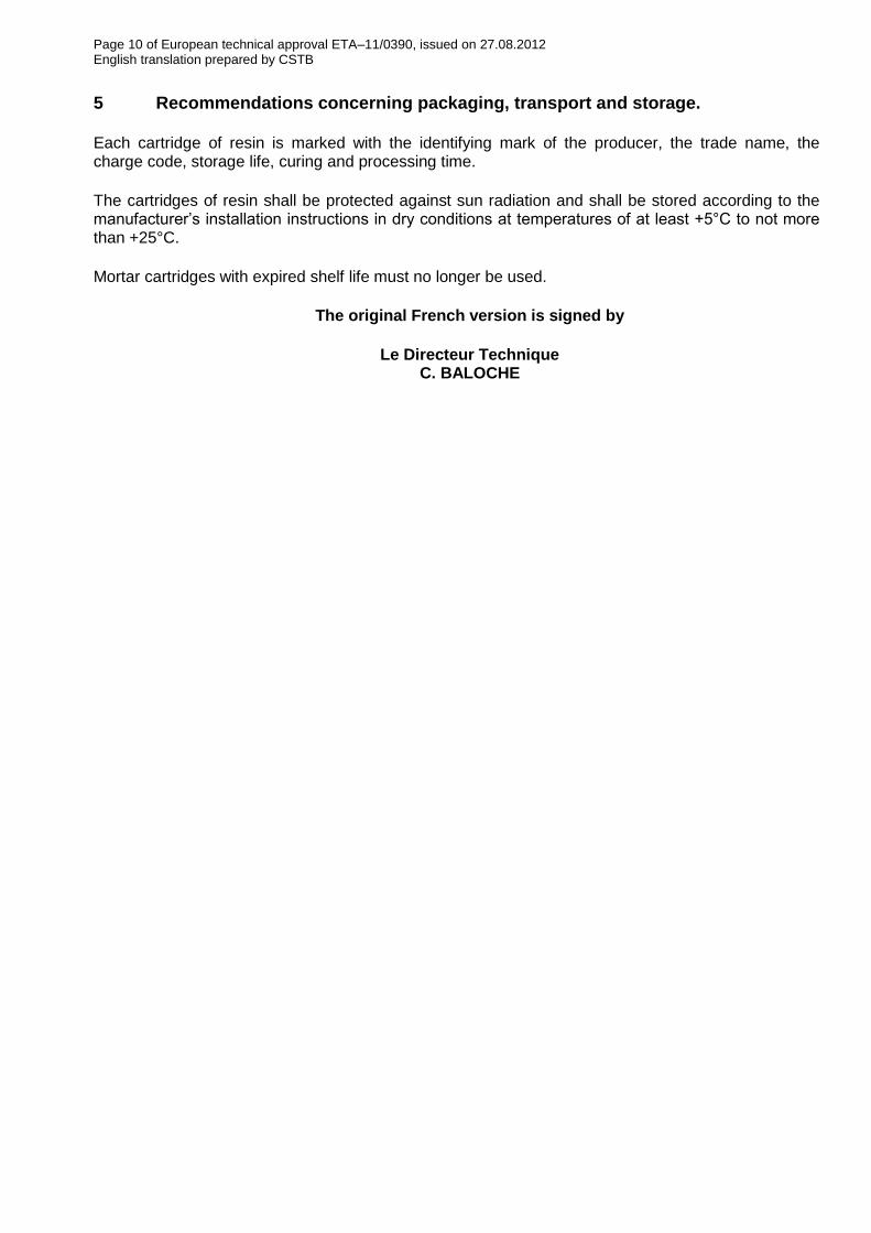
The post-installed rebar connection consists of injection mortar Hilti HIT-CT 1 and an embedded straight deformed reinforcing bar with properties of class B and C according to Annex C of EC 2 or the Hilti tension anchor HZA-R.
Injection mortar HIT-CT 1
Static mixer
Reinforcing bar according to EC 2 (see Annex 4):
Hilti Tension anchor HZA-R (see Annex 6):
Covered are post-installed rebar connections in non-carbonated concrete on the assumption only that the design of post-installed rebar connections is done in accordance to EC2.
Installation in dry or wet concrete, it must not be installed in flooded holes.
Temperature range: -40°C to +80°C (maximum long term temperature +50°C and maximum short term temperature +80°C)
Annex 1
Product description and intended use
Foil pack:
330 ml and 500 ml
HIT-CT 1
Page 12 of European Technical Approval ETA-11/0390, issued on 27.08.2012 English translation prepared by CSTB
of the European Technical Approval
ETA - 11/0390
Injection System Hilti HIT-CT 1 for rebar connection
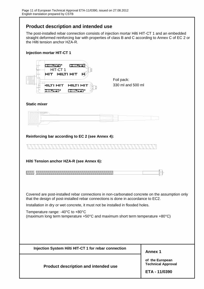
Annex 2
Examples of use
for rebars
Figure 1: Overlap joint for rebar connections of slabs and beams
0
v
10 ds
Figure 3: End anchoring of slabs or beams, designed as simply supported
Figure 4: Rebar connection for components stressed primarily in compression. The rebars are stressed in compression.
As
v = bd
N
Figure 5: Anchoring of reinforcement to cover the line of acting tensile force
acting tensile force bd
b,min
As,L ; ds,L
v
al
envelope of Med/z + Ned Note to Figure 1 to 5:
In the Figures no transverse reinforcement is plotted, the transverse reinforcement as required by EC 2 shall be present.
The shear transfer between old and new concrete shall be designed according to EC 2.
Description of the bonded-in rebars and overlap joints see Annex 4 and 5.
Prepare joint acc. to Section 4.3.1 and 4.3.2.7 of this approval
N,M,V
0
v
Prepare joint acc. to Section 4.3.1 and 4.3.2.7 of this approval
bd
bd
As,F
Prepare joint acc. to Section 4.3.1 and 4.3.2.7 of this approval
Figure 2: Overlap joint at a foundation of a column or wall where the rebars are stressed in tension
Page 13 of European Technical Approval ETA-11/0390, issued on 27.08.2012 English translation prepared by CSTB
of the European Technical Approval
ETA - 11/0390
Injection System Hilti HIT-CT 1 for rebar connection
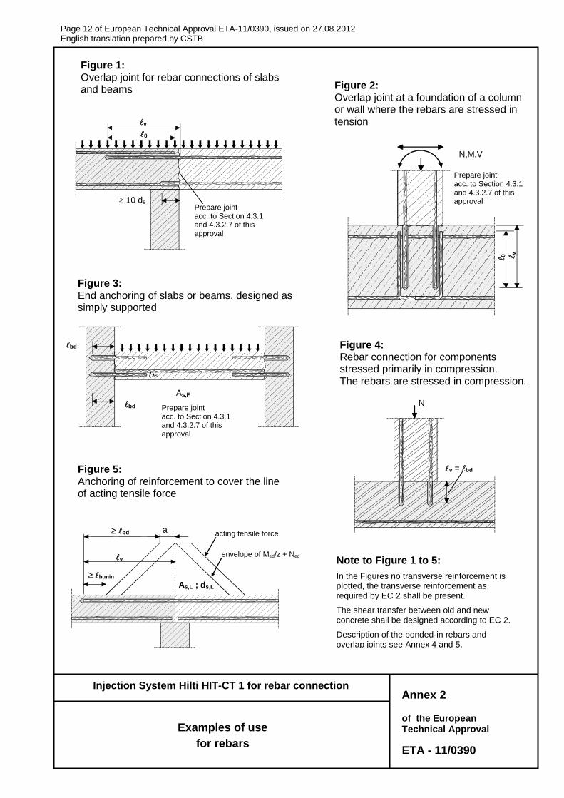
Note to Figure 6 to 8:
In the figures no transverse reinforcement is plotted. The transverse reinforcement as required by EN 1992-1-1 shall be present.
Only tension forces in the direction of the bar axis may be transmitted by the tension anchor HZA-R.
The tension force must be transferred via an overlap joint to the reinforcement in the building part.
The transmission of the shear load shall be ensured by appropriate additional measures, e.g. by shear lugs or by anchors with a European technical approval (ETA).
In the anchor plate, the holes for the tension anchor shall be executed as elongated holes with the axis in the direction of the shear force.
Description of anchorages and overlap joints see Annex 6 and 7.
Annex 3
Examples of use
for tension anchor HZA-R
Figure 6: Overlap joint of a column stressed in bending to a foundation
Figure 8:
Overlap joint for the anchorage of cantilever members
V
0 = v
e,ges Tension anchor HZA-R
Shear lug
Shear lug anchor
Figure 7: Overlap joint for the anchorage of barrier posts
Tension anchor HZA-R
shear lug
N, M, V
Tension anchor HZA-R
0
=
v
e,g
es
e,ges
0 = v
Tension anchor HZA-R
anchor
N, V
Page 14 of European Technical Approval ETA-11/0390, issued on 27.08.2012 English translation prepared by CSTB
of the European Technical Approval
ETA - 11/0390
Injection System Hilti HIT-CT 1 for rebar connection
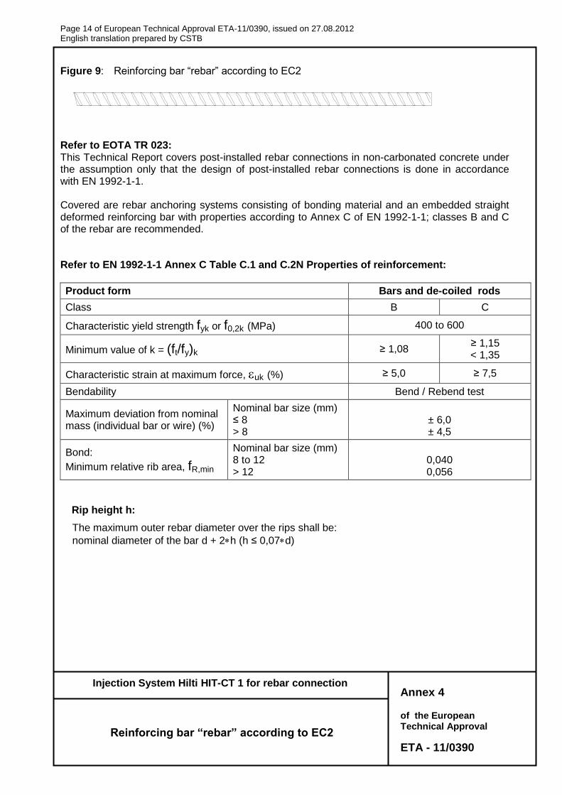
Figure 9: Reinforcing bar “rebar” according to EC2
Refer to EOTA TR 023: This Technical Report covers post-installed rebar connections in non-carbonated concrete under the assumption only that the design of post-installed rebar connections is done in accordance with EN 1992-1-1. Covered are rebar anchoring systems consisting of bonding material and an embedded straight deformed reinforcing bar with properties according to Annex C of EN 1992-1-1; classes B and C of the rebar are recommended. Refer to EN 1992-1-1 Annex C Table C.1 and C.2N Properties of reinforcement:
Product form Bars and de-coiled rods
Class B C
Characteristic yield strength fyk or f0,2k (MPa) 400 to 600
Minimum value of k = (ft/fy)k ≥ 1,08 ≥ 1,15 < 1,35
Characteristic strain at maximum force, uk (%) ≥ 5,0 ≥ 7,5
Bendability Bend / Rebend test
Maximum deviation from nominal mass (individual bar or wire) (%)
Nominal bar size (mm) ≤ 8 > 8
± 6,0 ± 4,5
Bond:
Minimum relative rib area, fR,min
Nominal bar size (mm) 8 to 12 > 12
0,040 0,056
Rip height h:
The maximum outer rebar diameter over the rips shall be:
nominal diameter of the bar d + 2h (h ≤ 0,07d)
Annex 4
Reinforcing bar “rebar” according to EC2
Page 15 of European Technical Approval ETA-11/0390, issued on 27.08.2012 English translation prepared by CSTB
of the European Technical Approval
ETA - 11/0390
Injection System Hilti HIT-CT 1 for rebar connection
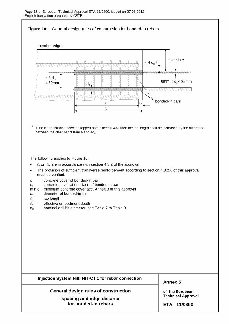
Figure 10: General design rules of construction for bonded-in rebars
1) If the clear distance between lapped bars exceeds 4ds, then the lap length shall be increased by the difference
between the clear bar distance and 4ds.
The following applies to Figure 10:
v or. 0 are in accordance with section 4.3.2 of the approval
The provision of sufficient transverse reinforcement according to section 4.3.2.6 of this approval must be verified.
c concrete cover of bonded-in bar c1 concrete cover at end-face of bonded-in bar min c minimum concrete cover acc. Annex 8 of this approval ds diameter of bonded-in bar
0 lap length
v effective embedment depth d0 nominal drill bit diameter, see Table 7 to Table 9
Annex 5
General design rules of construction
spacing and edge distance for bonded-in rebars
member edge
bonded-in bars
c
min c
5 d s
d 0
8mm d s 25mm 50mm
0 c 1
v
4 d s 1)
Page 16 of European Technical Approval ETA-11/0390, issued on 27.08.2012 English translation prepared by CSTB
of the European Technical Approval
ETA - 11/0390
Injection System Hilti HIT-CT 1 for rebar connection
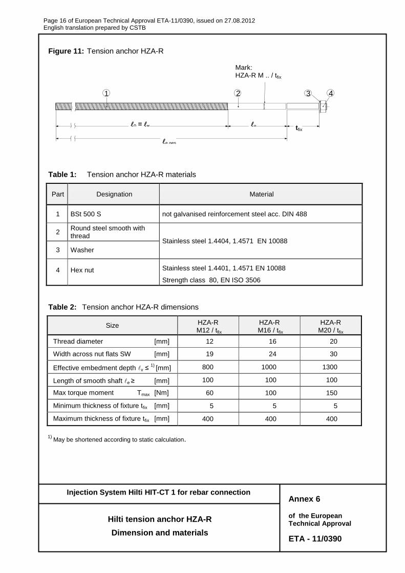
Figure 11: Tension anchor HZA-R
Table 1: Tension anchor HZA-R materials
Part Designation Material
1 BSt 500 S not galvanised reinforcement steel acc. DIN 488
2 Round steel smooth with thread
Stainless steel 1.4404, 1.4571 EN 10088
3 Washer
4 Hex nut Stainless steel 1.4401, 1.4571 EN 10088
Strength class 80, EN ISO 3506
Table 2: Tension anchor HZA-R dimensions
Size HZA-R M12 / tfix
HZA-R M16 / tfix
HZA-R(HCR) M16
HZA-R M20
HZA-R M20 / tfix
Thread diameter [mm] 12 16 20
Width across nut flats SW [mm] 19 24 30
Effective embedment depth v ≤ 1)
[mm]
[mm]
800 1000 1300
Length of smooth shaft e ≥ [mm] 100 100 100
Max torque moment Tmax [Nm] 60 100 150
Minimum thickness of fixture tfix [mm] 5 5 5
Maximum thickness of fixture tfix [mm] 400 400 400
1)
May be shortened according to static calculation.
Annex 6
Hilti tension anchor HZA-R
Dimension and materials
HZ
A-R
M
4321H
ZA
-R M
4321
0 = v e tfix
e,ges
Mark: HZA-R M .. / tfix
Page 17 of European Technical Approval ETA-11/0390, issued on 27.08.2012 English translation prepared by CSTB
of the European Technical Approval
ETA - 11/0390
Injection System Hilti HIT-CT 1 for rebar connection
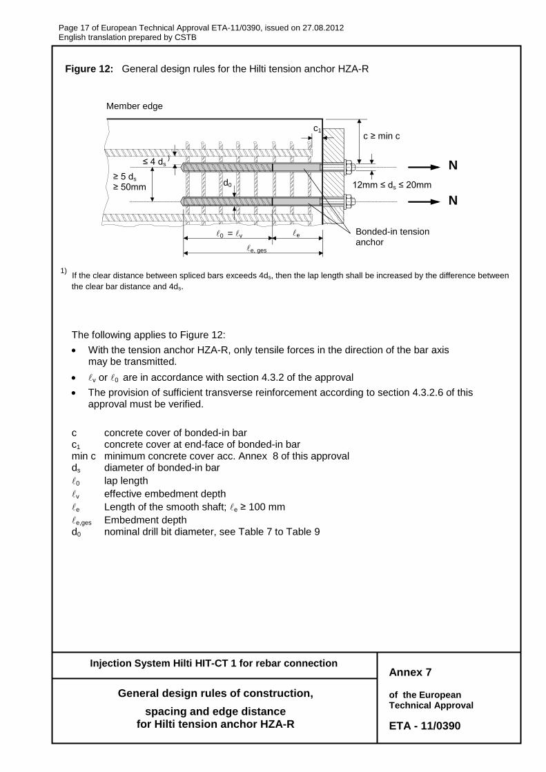
Figure 12: General design rules for the Hilti tension anchor HZA-R
1) If the clear distance between spliced bars exceeds 4ds, then the lap length shall be increased by the difference between
the clear bar distance and 4ds.
The following applies to Figure 12:
With the tension anchor HZA-R, only tensile forces in the direction of the bar axis may be transmitted.
v or 0 are in accordance with section 4.3.2 of the approval
The provision of sufficient transverse reinforcement according to section 4.3.2.6 of this approval must be verified.
c concrete cover of bonded-in bar c1 concrete cover at end-face of bonded-in bar min c minimum concrete cover acc. Annex 8 of this approval ds diameter of bonded-in bar
0 lap length
v effective embedment depth
e Length of the smooth shaft; e ≥ 100 mm
e,ges Embedment depth d0 nominal drill bit diameter, see Table 7 to Table 9
Annex 7
General design rules of construction,
spacing and edge distance for Hilti tension anchor HZA-R
≥ 5 ds ≥ 50mm
d0
c1
≤ 4 ds )
c ≥ min c
12mm ≤ ds ≤ 20mm
N
N
0 = v e
e, ges
Member edge
Bonded-in tension anchor
Page 18 of European Technical Approval ETA-11/0390, issued on 27.08.2012 English translation prepared by CSTB
of the European Technical Approval
ETA - 11/0390
Injection System Hilti HIT-CT 1 for rebar connection
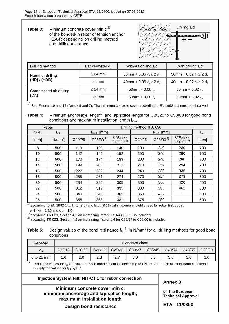
Table 3: Minimum concrete cover min c 1)
of the bonded-in rebar or tension anchor HZA-R depending on drilling method and drilling tolerance
Drilling method Bar diameter ds Without drilling aid With drilling aid
Hammer drilling (HD) / (HDB)
24 mm
30mm + 0,06 v 2 ds 30mm + 0,02 v 2 ds
25 mm 40mm + 0,06 v 2 ds 40mm + 0,02 v 2 ds
Compressed air drilling (CA)
24 mm 50mm + 0,08 v 50mm + 0,02 v
25 mm 60mm + 0,08 v 60mm + 0,02 v
1) See Figures 10 and 12 (Annex 5 and 7). The minimum concrete cover according to EN 1992-1-1 must be observed
Table 4: Minimum anchorage length1) and lap splice length for C20/25 to C50/60 for good bond
conditions and maximum installation length lmax
Rebar Drilling method HD, CA
Ø ds fy,k lb,min [mm] l0,min [mm] lmax
[mm] [N/mm²] C20/25 C25/30 2) C30/37-
C50/60 3) C20/25 C25/30
2) C30/37-
C50/60 3) [mm]
8 500 113 120 140 200 240 280 700
10 500 142 145 152 200 240 280 700
12 500 170 174 183 200 240 280 700
14 500 199 203 213 210 252 294 700
16 500 227 232 244 240 288 336 700
18 500 255 261 274 270 324 378 500
20 500 284 290 305 300 360 420 500
22 500 312 319 335 330 396 462 500
24 500 340 348 365 360 432 - 500
25 500 355 363 381 375 450 - 500 1)
according to EN 1992-1-1: lb,min (8.6) and l0,min (8.11) with maximum yield stress for rebar BSt 500S,
with M = 1,15 and α 6 = 1,0 2)
according TR 023, Section 4.2 an increasing factor 1,2 for C25/30 is included 3)
according TR 023, Section 4.2 an increasing factor 1,4 for C30/37 to C50/60 is included
Table 5: Design values of the bond resistance fbd 1) in N/mm² for all drilling methods for good bond
conditions
Rebar-Ø Concrete class
ds C12/15 C16/20 C20/25 C25/30 C30/37 C35/45 C40/50 C45/55 C50/60
8 to 25 mm 1,6 2,0 2,3 2,7 3,0 3,0 3,0 3,0 3,0
1) Tabulated values for fbd are valid for good bond conditions according to EN 1992-1-1. For all other bond conditions
multiply the values for fbd by 0.7.
Annex 8
Minimum concrete cover min c, minimum anchorage and lap splice length,
maximum installation length
Design bond resistance
Drilling aid
Page 19 of European Technical Approval ETA-11/0390, issued on 27.08.2012 English translation prepared by CSTB
of the European Technical Approval
ETA - 11/0390
Injection System Hilti HIT-CT 1 for rebar connection
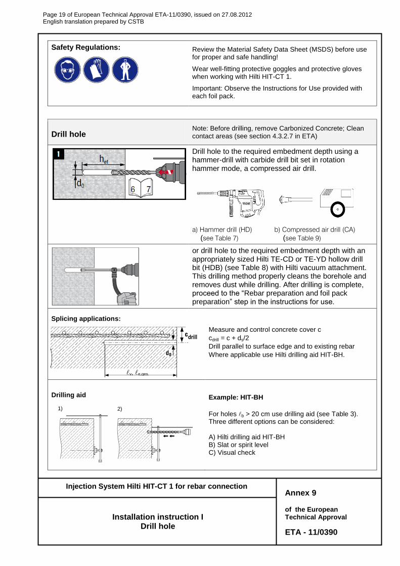
Safety Regulations:
Review the Material Safety Data Sheet (MSDS) before use for proper and safe handling!
Wear well-fitting protective goggles and protective gloves when working with Hilti HIT-CT 1.
Important: Observe the Instructions for Use provided with each foil pack.
Drill hole Note: Before drilling, remove Carbonized Concrete; Clean contact areas (see section 4.3.2.7 in ETA)
Drill hole to the required embedment depth using a hammer-drill with carbide drill bit set in rotation hammer mode, a compressed air drill.
a) Hammer drill (HD) b) Compressed air drill (CA) (see Table 7) (see Table 9)
or drill hole to the required embedment depth with an appropriately sized Hilti TE-CD or TE-YD hollow drill bit (HDB) (see Table 8) with Hilti vacuum attachment. This drilling method properly cleans the borehole and removes dust while drilling. After drilling is complete, proceed to the “Rebar preparation and foil pack preparation” step in the instructions for use.
Splicing applications:
Measure and control concrete cover c
cdrill = c + ds/2
Drill parallel to surface edge and to existing rebar
Where applicable use Hilti drilling aid HIT-BH.
Drilling aid
Example: HIT-BH
For holes b > 20 cm use drilling aid (see Table 3). Three different options can be considered: A) Hilti drilling aid HIT-BH B) Slat or spirit level C) Visual check
Annex 9
Installation instruction I Drill hole
1) 2)
drill
v, e,ges.
Page 20 of European Technical Approval ETA-11/0390, issued on 27.08.2012 English translation prepared by CSTB
of the European Technical Approval
ETA - 11/0390
Injection System Hilti HIT-CT 1 for rebar connection
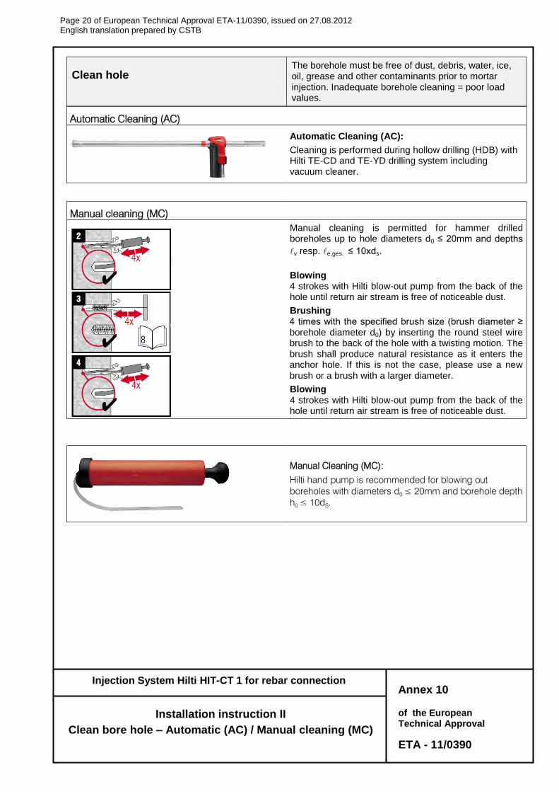
Clean hole
The borehole must be free of dust, debris, water, ice, oil, grease and other contaminants prior to mortar injection. Inadequate borehole cleaning = poor load values.
Automatic Cleaning (AC)
Automatic Cleaning (AC):
Cleaning is performed during hollow drilling (HDB) with Hilti TE-CD and TE-YD drilling system including vacuum cleaner.
Manual cleaning (MC)
Manual cleaning is permitted for hammer drilled boreholes up to hole diameters d0 ≤ 20mm and depths
v resp. e,ges. ≤ 10xds.
Blowing 4 strokes with Hilti blow-out pump from the back of the hole until return air stream is free of noticeable dust.
Brushing 4 times with the specified brush size (brush diameter ≥ borehole diameter d0) by inserting the round steel wire brush to the back of the hole with a twisting motion. The brush shall produce natural resistance as it enters the anchor hole. If this is not the case, please use a new brush or a brush with a larger diameter.
Blowing 4 strokes with Hilti blow-out pump from the back of the hole until return air stream is free of noticeable dust.
Manual Cleaning (MC):
Hilti hand pump is recommended for blowing out
boreholes with diameters d0 ≤ 20mm and borehole depth
h0 ≤ 10d
S.
Annex 10
Installation instruction II
Clean bore hole – Automatic (AC) / Manual cleaning (MC)
Page 21 of European Technical Approval ETA-11/0390, issued on 27.08.2012 English translation prepared by CSTB
of the European Technical Approval
ETA - 11/0390
Injection System Hilti HIT-CT 1 for rebar connection
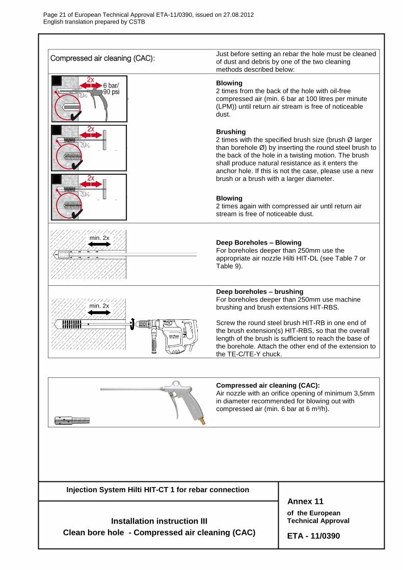
Compressed air cleaning (CAC): Just before setting an rebar the hole must be cleaned of dust and debris by one of the two cleaning methods described below:
Blowing 2 times from the back of the hole with oil-free compressed air (min. 6 bar at 100 litres per minute (LPM)) until return air stream is free of noticeable dust.
Brushing 2 times with the specified brush size (brush Ø larger than borehole Ø) by inserting the round steel brush to the back of the hole in a twisting motion. The brush shall produce natural resistance as it enters the anchor hole. If this is not the case, please use a new brush or a brush with a larger diameter.
Blowing 2 times again with compressed air until return air stream is free of noticeable dust.
Deep Boreholes – Blowing For boreholes deeper than 250mm use the appropriate air nozzle Hilti HIT-DL (see Table 7 or Table 9).
Deep boreholes – brushing For boreholes deeper than 250mm use machine brushing and brush extensions HIT-RBS. Screw the round steel brush HIT-RB in one end of the brush extension(s) HIT-RBS, so that the overall length of the brush is sufficient to reach the base of the borehole. Attach the other end of the extension to the TE-C/TE-Y chuck.
Compressed air cleaning (CAC): Air nozzle with an orifice opening of minimum 3,5mm in diameter recommended for blowing out with compressed air (min. 6 bar at 6 m³/h).
Annex 11
Installation instruction III
Clean bore hole - Compressed air cleaning (CAC)
min. 2x
min. 2x
Page 22 of European Technical Approval ETA-11/0390, issued on 27.08.2012 English translation prepared by CSTB
of the European Technical Approval
ETA - 11/0390
Injection System Hilti HIT-CT 1 for rebar connection
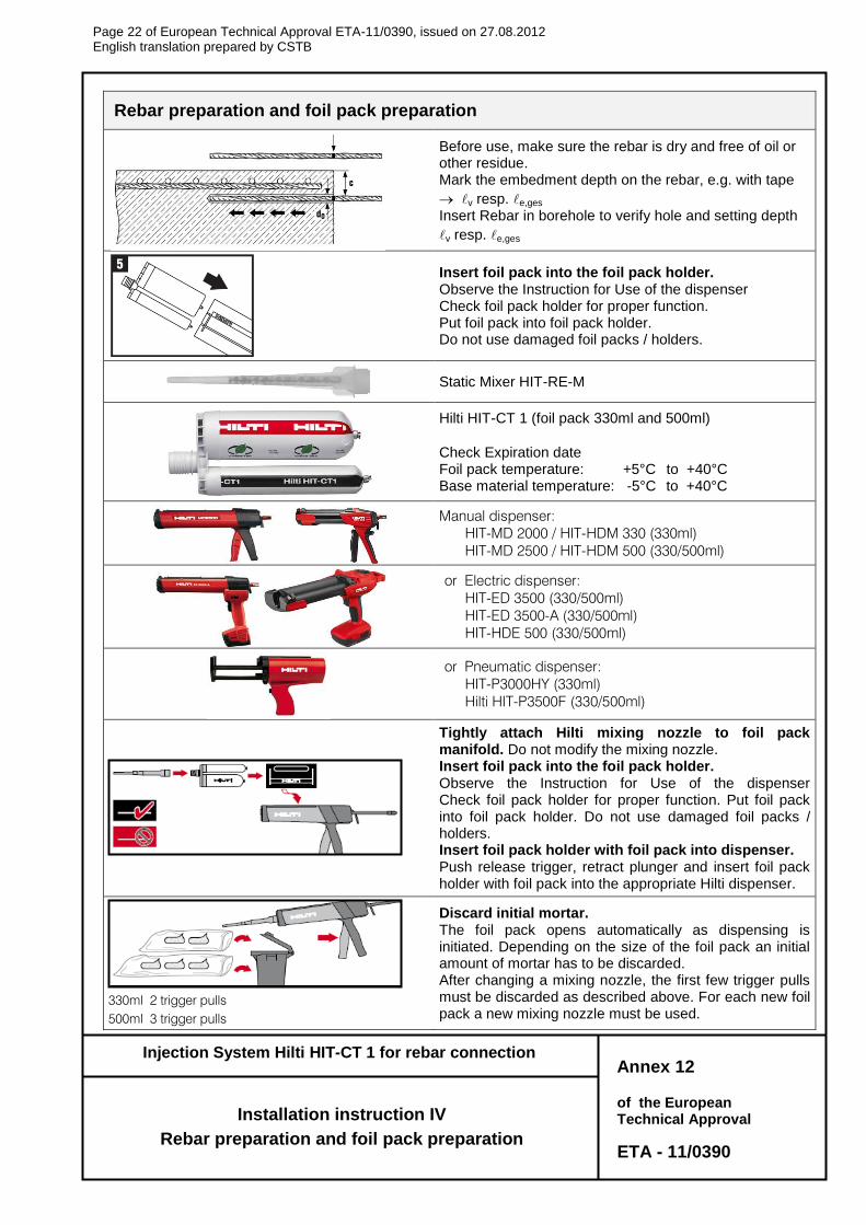
Rebar preparation and foil pack preparation
Before use, make sure the rebar is dry and free of oil or other residue. Mark the embedment depth on the rebar, e.g. with tape
v resp. e,ges Insert Rebar in borehole to verify hole and setting depth
v resp. e,ges
Insert foil pack into the foil pack holder. Observe the Instruction for Use of the dispenser Check foil pack holder for proper function. Put foil pack into foil pack holder. Do not use damaged foil packs / holders.
Static Mixer HIT-RE-M
Hilti HIT-CT 1 (foil pack 330ml and 500ml)
Check Expiration date Foil pack temperature: +5°C to +40°C Base material temperature: -5°C to +40°C
Manual dispenser:
HIT-MD 2000 / HIT-HDM 330 (330ml)
HIT-MD 2500 / HIT-HDM 500 (330/500ml)
or Electric dispenser:
HIT-ED 3500 (330/500ml)
HIT-ED 3500-A (330/500ml)
HIT-HDE 500 (330/500ml)
or Pneumatic dispenser:
HIT-P3000HY (330ml)
Hilti HIT-P3500F (330/500ml)
Tightly attach Hilti mixing nozzle to foil pack manifold. Do not modify the mixing nozzle. Insert foil pack into the foil pack holder. Observe the Instruction for Use of the dispenser Check foil pack holder for proper function. Put foil pack into foil pack holder. Do not use damaged foil packs / holders. Insert foil pack holder with foil pack into dispenser. Push release trigger, retract plunger and insert foil pack holder with foil pack into the appropriate Hilti dispenser.
330ml 2 trigger pulls
500ml 3 trigger pulls
Discard initial mortar. The foil pack opens automatically as dispensing is initiated. Depending on the size of the foil pack an initial amount of mortar has to be discarded. After changing a mixing nozzle, the first few trigger pulls must be discarded as described above. For each new foil pack a new mixing nozzle must be used.
Annex 12
Installation instruction IV
Rebar preparation and foil pack preparation
Page 23 of European Technical Approval ETA-11/0390, issued on 27.08.2012 English translation prepared by CSTB
of the European Technical Approval
ETA - 11/0390
Injection System Hilti HIT-CT 1 for rebar connection
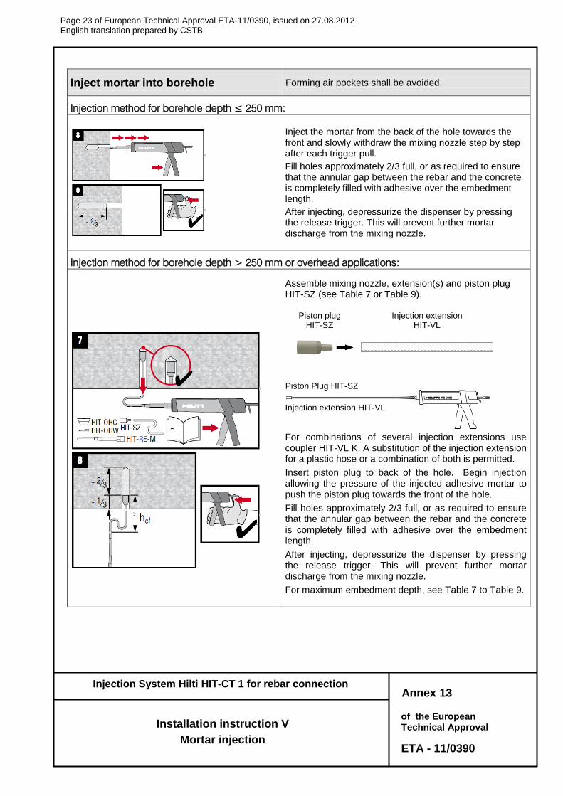
Inject mortar into borehole Forming air pockets shall be avoided.
Injection method for borehole depth ≤ 250 mm:
Inject the mortar from the back of the hole towards the front and slowly withdraw the mixing nozzle step by step after each trigger pull.
Fill holes approximately 2/3 full, or as required to ensure that the annular gap between the rebar and the concrete is completely filled with adhesive over the embedment length.
After injecting, depressurize the dispenser by pressing the release trigger. This will prevent further mortar discharge from the mixing nozzle.
Injection method for borehole depth > 250 mm or overhead applications:
Assemble mixing nozzle, extension(s) and piston plug HIT-SZ (see Table 7 or Table 9).
For combinations of several injection extensions use coupler HIT-VL K. A substitution of the injection extension for a plastic hose or a combination of both is permitted.
Insert piston plug to back of the hole. Begin injection allowing the pressure of the injected adhesive mortar to push the piston plug towards the front of the hole.
Fill holes approximately 2/3 full, or as required to ensure that the annular gap between the rebar and the concrete is completely filled with adhesive over the embedment length.
After injecting, depressurize the dispenser by pressing the release trigger. This will prevent further mortar discharge from the mixing nozzle.
For maximum embedment depth, see Table 7 to Table 9.
Annex 13
Installation instruction V
Mortar injection
Injection extension HIT-VL
Piston Plug HIT-SZ
Piston plug HIT-SZ
Injection extension HIT-VL
Page 24 of European Technical Approval ETA-11/0390, issued on 27.08.2012 English translation prepared by CSTB
of the European Technical Approval
ETA - 11/0390
Injection System Hilti HIT-CT 1 for rebar connection
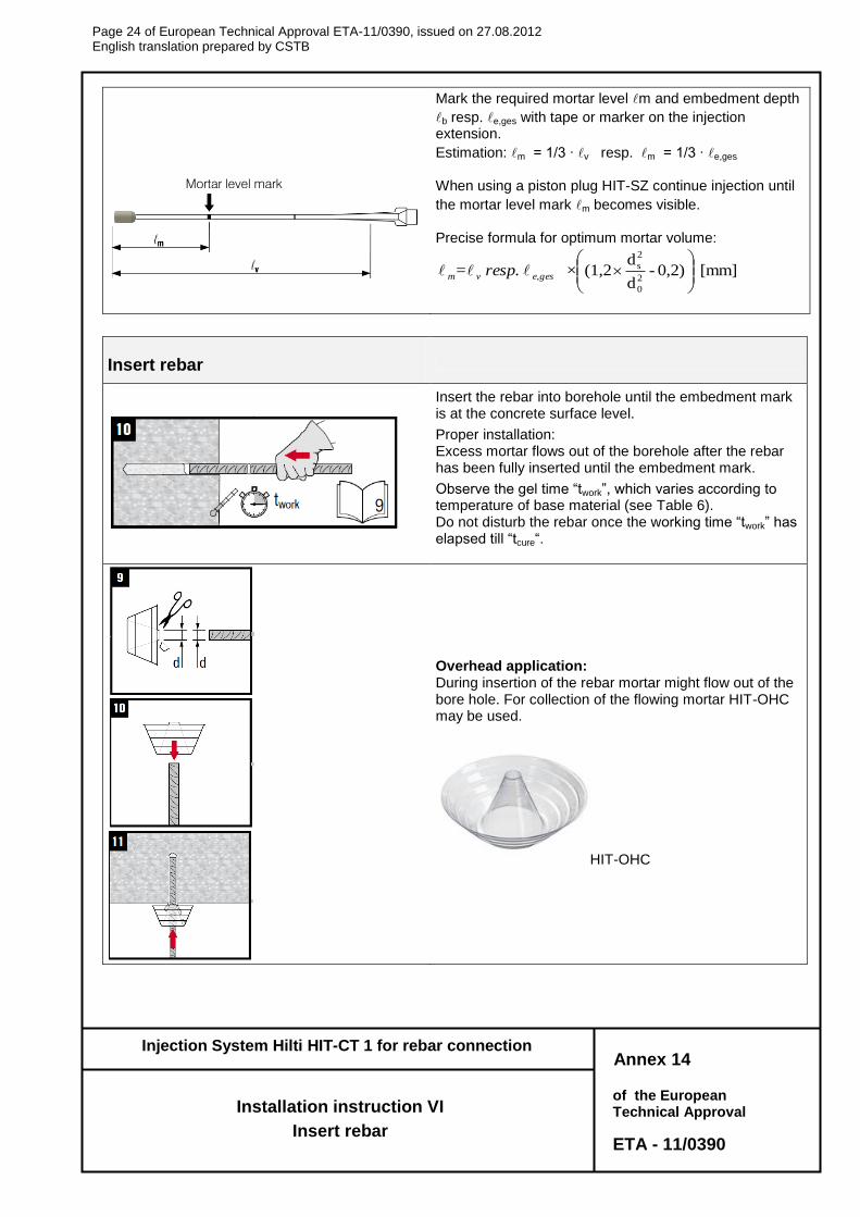
Mark the required mortar level m and embedment depth
b resp. e,ges with tape or marker on the injection extension.
Estimation: m = 1/3 ∙ v resp. m = 1/3 ∙ e,ges When using a piston plug HIT-SZ continue injection until
the mortar level mark m becomes visible. Precise formula for optimum mortar volume:
[mm]0,2)-d
d(1,2
2
0
2
s
×resp.= e,gesvm
Insert rebar
Insert the rebar into borehole until the embedment mark is at the concrete surface level.
Proper installation: Excess mortar flows out of the borehole after the rebar has been fully inserted until the embedment mark.
Observe the gel time “twork”, which varies according to temperature of base material (see Table 6). Do not disturb the rebar once the working time “twork” has elapsed till “tcure“.
Overhead application: During insertion of the rebar mortar might flow out of the bore hole. For collection of the flowing mortar HIT-OHC may be used.
HIT-OHC
Annex 14
Installation instruction VI
Insert rebar
Mortar level mark
v., e,ges
Page 25 of European Technical Approval ETA-11/0390, issued on 27.08.2012 English translation prepared by CSTB
of the European Technical Approval
ETA - 11/0390
Injection System Hilti HIT-CT 1 for rebar connection
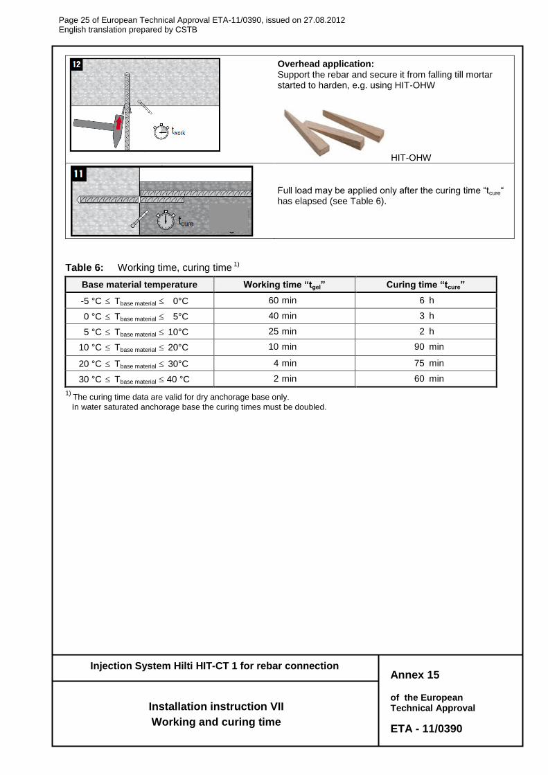
Overhead application: Support the rebar and secure it from falling till mortar started to harden, e.g. using HIT-OHW
HIT-OHW
Full load may be applied only after the curing time “tcure“ has elapsed (see Table 6).
Table 6: Working time, curing time 1)
Base material temperature Working time “tgel” Curing time “tcure”
-5 °C Tbase material 0°C 60 min 6 h
0 °C Tbase material 5°C 40 min 3 h
5 °C Tbase material 10°C 25 min 2 h
10 °C Tbase material 20°C 10 min 90 min
20 °C Tbase material 30°C 4 min 75 min
30 °C Tbase material 40 °C 2 min 60 min
1) The curing time data are valid for dry anchorage base only.
In water saturated anchorage base the curing times must be doubled.
Annex 15
Installation instruction VII
Working and curing time
Page 26 of European Technical Approval ETA-11/0390, issued on 27.08.2012 English translation prepared by CSTB
of the European Technical Approval
ETA - 11/0390
Injection System Hilti HIT-CT 1 for rebar connection
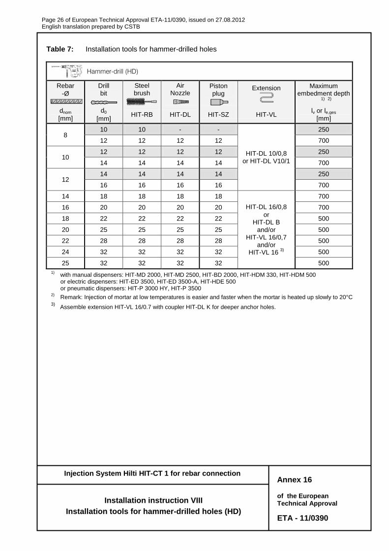
Table 7: Installation tools for hammer-drilled holes
Hammer-drill (HD)
Rebar
-Ø
Drill bit
Steel brush
Air Nozzle
Piston plug
Extension
Maximum embedment depth
1) 2)
dnom
[mm]
d0
[mm] HIT-RB HIT-DL HIT-SZ HIT-VL
lv or le,ges
[mm]
8 10 10 - -
HIT-DL 10/0,8 or HIT-DL V10/1
250
12 12 12 12 700
10 12 12 12 12 250
14 14 14 14 700
12 14 14 14 14 250
16 16 16 16 700
14 18 18 18 18
HIT-DL 16/0,8
or HIT-DL B
and/or HIT-VL 16/0,7
and/or HIT-VL 16
3)
700
16 20 20 20 20 700
18 22 22 22 22 500
20 25 25 25 25 500
22 28 28 28 28 500
24 32 32 32 32 500
25 32 32 32 32 500
1) with manual dispensers: HIT-MD 2000, HIT-MD 2500, HIT-BD 2000, HIT-HDM 330, HIT-HDM 500
or electric dispensers: HIT-ED 3500, HIT-ED 3500-A, HIT-HDE 500 or pneumatic dispensers: HIT-P 3000 HY, HIT-P 3500
2) Remark: Injection of mortar at low temperatures is easier and faster when the mortar is heated up slowly to 20°C
3) Assemble extension HIT-VL 16/0.7 with coupler HIT-DL K for deeper anchor holes.
Annex 16
Installation instruction VIII
Installation tools for hammer-drilled holes (HD)
Page 27 of European Technical Approval ETA-11/0390, issued on 27.08.2012 English translation prepared by CSTB
of the European Technical Approval
ETA - 11/0390
Injection System Hilti HIT-CT 1 for rebar connection
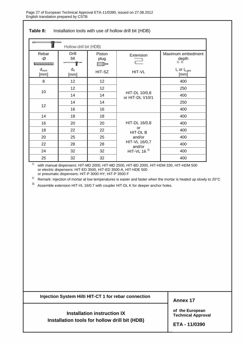
Table 8: Installation tools with use of hollow drill bit (HDB)
Hollow-drill bit (HDB)
Rebar
-Ø
Drill bit
Piston plug
Extension
Maximum embedment depth
1) 2)
dnom
[mm]
d0
[mm] HIT-SZ HIT-VL
lv or le,ges
[mm]
8 12 12
HIT-DL 10/0,8 or HIT-DL V10/1
400
10 12 12 250
14 14 400
12 14 14 250
16 16 400
14 18 18
HIT-DL 16/0,8
or HIT-DL B
and/or HIT-VL 16/0,7
and/or HIT-VL 16
3)
400
16 20 20 400
18 22 22 400
20 25 25 400
22 28 28 400
24 32 32 400
25 32 32 400
1) with manual dispensers: HIT-MD 2000, HIT-MD 2500, HIT-BD 2000, HIT-HDM 330, HIT-HDM 500
or electric dispensers: HIT-ED 3500, HIT-ED 3500-A, HIT-HDE 500 or pneumatic dispensers: HIT-P 3000 HY, HIT-P 3500 F
2) Remark: Injection of mortar at low temperatures is easier and faster when the mortar is heated up slowly to 20°C
3) Assemble extension HIT-VL 16/0.7 with coupler HIT-DL K for deeper anchor holes.
Annex 17
Installation instruction IX
Installation tools for hollow drill bit (HDB)
Page 28 of European technical approval ETA–11/0390, issued on 27.08.2012 English translation prepared by CSTB
of the European Technical Approval
ETA - 11/0390
Injection System Hilti HIT-CT 1 for rebar connection
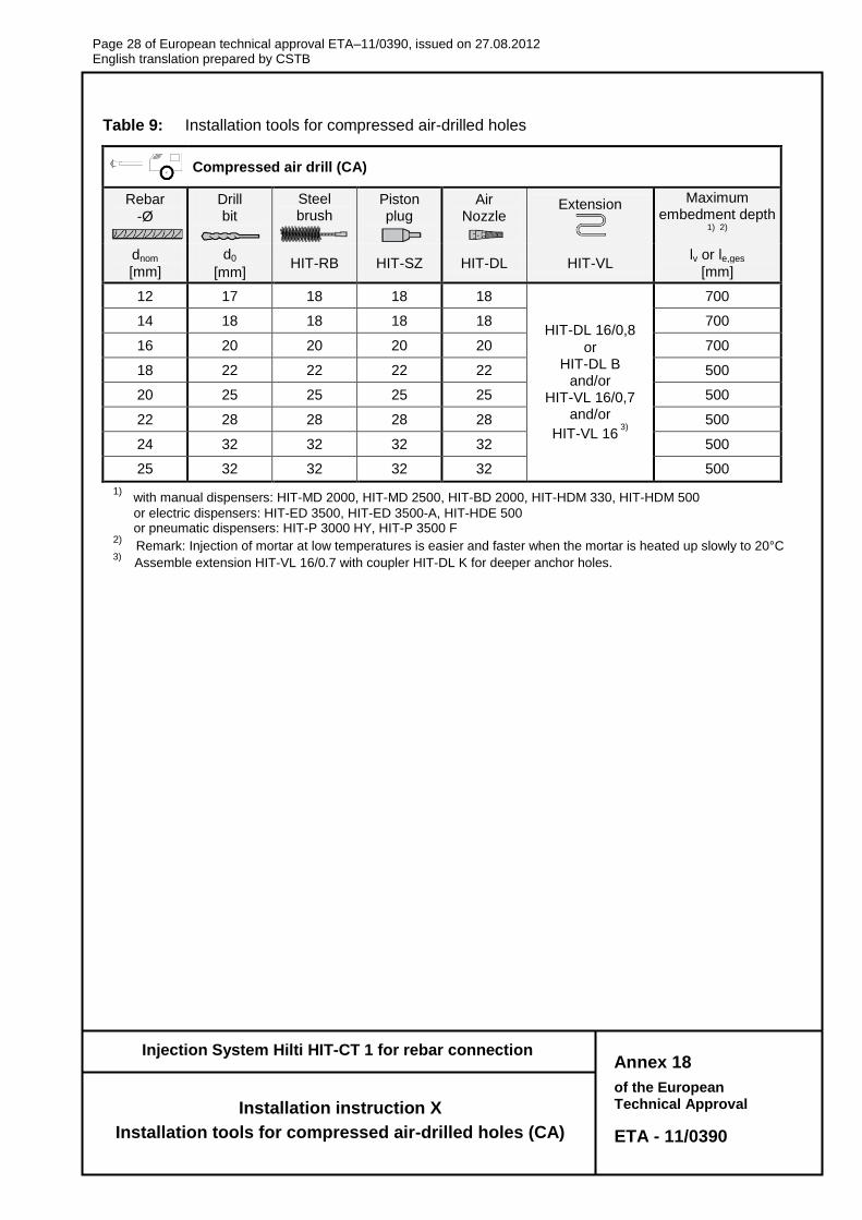
Table 9: Installation tools for compressed air-drilled holes
Compressed air drill (CA)
Rebar
-Ø
Drill bit
Steel brush
Piston plug
Air Nozzle
Extension
Maximum embedment depth
1) 2)
dnom
[mm]
d0
[mm] HIT-RB HIT-SZ HIT-DL HIT-VL
lv or le,ges
[mm]
12 17 18 18 18
HIT-DL 16/0,8
or HIT-DL B
and/or HIT-VL 16/0,7
and/or
HIT-VL 16 3)
700
14 18 18 18 18 700
16 20 20 20 20 700
18 22 22 22 22 500
20 25 25 25 25 500
22 28 28 28 28 500
24 32 32 32 32 500
25 32 32 32 32 500
1) with manual dispensers: HIT-MD 2000, HIT-MD 2500, HIT-BD 2000, HIT-HDM 330, HIT-HDM 500
or electric dispensers: HIT-ED 3500, HIT-ED 3500-A, HIT-HDE 500 or pneumatic dispensers: HIT-P 3000 HY, HIT-P 3500 F
2) Remark: Injection of mortar at low temperatures is easier and faster when the mortar is heated up slowly to 20°C
3) Assemble extension HIT-VL 16/0.7 with coupler HIT-DL K for deeper anchor holes.
Annex 18
Installation instruction X
Installation tools for compressed air-drilled holes (CA)
Page 29 of European technical approval ETA–11/0390, issued on 27.08.2012 English translation prepared by CSTB
of the European Technical Approval
ETA - 11/0390
Injection System Hilti HIT-CT 1 for rebar connection
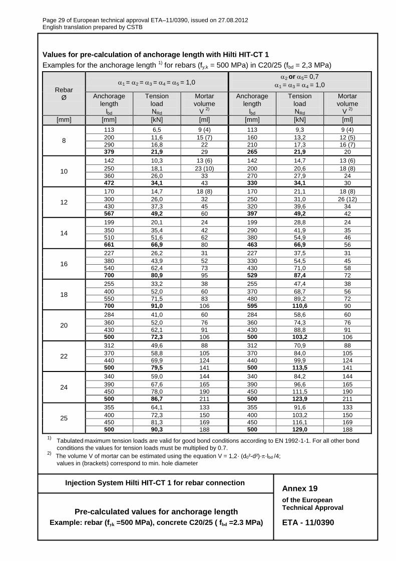
Values for pre-calculation of anchorage length with Hilti HIT-CT 1
Examples for the anchorage length 1) for rebars (fy,k = 500 MPa) in C20/25 (fbd = 2,3 MPa)
Rebar Ø
1 = 2 = 3 = 4 = 5 = 1,0 2 or 5= 0,7
1 = 3 = 4 = 1,0
Anchorage length
lbd
Tension load NRd
Mortar volume
V 2)
Anchorage length
lbd
Tension load NRd
Mortar volume
V 2)
[mm] [mm] [kN] [ml] [mm] [kN] [ml]
8
113 6,5 9 (4) 113 9,3 9 (4)
200 11,6 15 (7) 160 13,2 12 (5)
290 16,8 22 210 17,3 16 (7)
379 21,9 29 265 21,9 20
10
142 10,3 13 (6) 142 14,7 13 (6)
250 18,1 23 (10) 200 20,6 18 (8)
360 26,0 33 270 27,9 24
472 34,1 43 330 34,1 30
12
170 14,7 18 (8) 170 21,1 18 (8)
300 26,0 32 250 31,0 26 (12)
430 37,3 45 320 39,6 34
567 49,2 60 397 49,2 42
14
199 20,1 24 199 28,8 24
350 35,4 42 290 41,9 35
510 51,6 62 380 54,9 46
661 66,9 80 463 66,9 56
16
227 26,2 31 227 37,5 31
380 43,9 52 330 54,5 45
540 62,4 73 430 71,0 58
700 80,9 95 529 87,4 72
18
255 33,2 38 255 47,4 38
400 52,0 60 370 68,7 56
550 71,5 83 480 89,2 72
700 91,0 106 595 110,6 90
20
284 41,0 60 284 58,6 60
360 52,0 76 360 74,3 76
430 62,1 91 430 88,8 91
500 72,3 106 500 103,2 106
22
312 49,6 88 312 70,9 88
370 58,8 105 370 84,0 105
440 69,9 124 440 99,9 124
500 79,5 141 500 113,5 141
24
340 59,0 144 340 84,2 144
390 67,6 165 390 96,6 165
450 78,0 190 450 111,5 190
500 86,7 211 500 123,9 211
25
355 64,1 133 355 91,6 133
400 72,3 150 400 103,2 150
450 81,3 169 450 116,1 169
500 90,3 188 500 129,0 188
1) Tabulated maximum tension loads are valid for good bond conditions according to EN 1992-1-1. For all other bond
conditions the values for tension loads must be multiplied by 0.7. 2)
The volume V of mortar can be estimated using the equation V = 1,2· (d0²-d²)··lbd /4;
values in (brackets) correspond to min. hole diameter
Annex 19
Pre-calculated values for anchorage length
Example: rebar (fyk =500 MPa), concrete C20/25 ( fbd =2.3 MPa)
Page 30 of European technical approval ETA–11/0390, issued on 27.08.2012 English translation prepared by CSTB
of the European Technical Approval
ETA - 11/0390
Injection System Hilti HIT-CT 1 for rebar connection
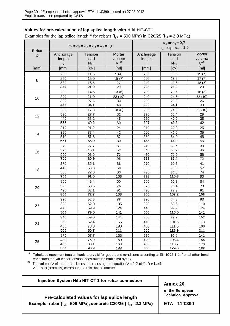
Values for pre-calculation of lap splice length with Hilti HIT-CT 1
Examples for the lap splice length 1) for rebars (fy,k = 500 MPa) in C20/25 (fbd = 2,3 MPa)
Rebar Ø
1 = 2 = 3 = 4 = 5 = 1,0 2 or 5= 0,7
1 = 3 = 4 = 1,0
Anchorage length
lbd
Tension load NRd
Mortar volume
V 2)
Anchorage length
lbd
Tension load NRd
Mortar volume
V 2)
[mm] [mm] [kN] [ml] [mm] [kN] [ml]
8
200 11,6 9 (4) 200 16,5 15 (7)
260 15,0 15 (7) 220 18,2 17 (7)
320 18,5 22 240 19,8 18 (8)
379 21,9 29 265 21,9 20
10
200 14,5 13 (6) 200 20,6 18 (8)
290 21,0 23 (10) 240 24,8 22 (10)
380 27,5 33 290 29,9 26
472 34,1 43 330 34,1 30
12
200 17,3 18 (8) 200 24,8 21 (10)
320 27,7 32 270 33,4 29
440 38,2 45 330 40,9 35
567 49,2 60 397 49,2 42
14
210 21,2 24 210 30,3 25
360 36,4 42 290 41,9 35
510 51,6 62 380 54,9 46
661 66,9 80 463 66,9 56
16
240 27,7 31 240 39,6 33
390 45,1 52 340 56,2 46
550 63,6 73 430 71,0 58
700 80,9 95 529 87,4 72
18
270 35,1 38 270 50,2 41
410 53,3 60 380 70,6 57
560 72,8 83 490 91,0 74
700 91,0 106 595 110,6 90
20
300 43,4 60 300 61,9 64
370 53,5 76 370 76,4 78
430 62,1 91 430 88,8 91
500 72,3 106 500 103,2 106
22
330 52,5 88 330 74,9 93
390 62,0 105 390 88,6 110
440 69,9 124 440 99,9 124
500 79,5 141 500 113,5 141
24
340 59,0 144 360 89,2 152
360 62,4 165 410 101,6 173
450 78,0 190 450 111,5 190
500 86,7 211 500 123,9 211
25
375 67,7 133 375 96,8 141
420 75,9 150 420 108,4 158
460 83,1 169 460 118,7 173
500 90,3 188 500 129,0 188
1) Tabulated maximum tension loads are valid for good bond conditions according to EN 1992-1-1. For all other bond
conditions the values for tension loads must be multiplied by 0.7. 2)
The volume V of mortar can be estimated using the equation V = 1,2·(d0²-d²)··lbd /4;
values in (brackets) correspond to min. hole diameter
Annex 20
Pre-calculated values for lap splice length
Example: rebar (fyk =500 MPa), concrete C20/25 ( fbd =2.3 MPa)