Embed Size (px)
Citation preview
Experimental results on Swirl-stabilized Syngas flames by transverse fuel injection
A.Bouziane, F.Cozzi, , A.Lahcene, M.Aminallah, A.Khalfi A. Coghe,
Corresponding author
Corresponding author. Tel.: +213 -779628346 fax : 0021348546322
E-mail address: [email protected](A.Bouziane)Address : Département de Génie Mécanique, Laboratoire de Matériaux et Systèmes Réactifs, Rue de Sétif, 19, 22000 Sidi bel abbés, Algérie.Corresponding author. Tel.: +213 -7772782574 fax : 0021348546322E-mail address: [email protected](A.Khalfi)Address : Département de Génie Mécanique, Laboratoire de Matériaux et Systèmes Réactifs, Rue de Sétif, 19, 22000 Sidi bel abbés, Algérie.
Corresponding author. Tel.: +39-02-2399.8616; Fax: 02-2399.8566E-mail address: [email protected] (F.Cozzi).Dipartimento di Energetica, Politecnico di Milano, via La Masa, 34, 20156 Milano, Italy
Corresponding author. Tel.: +39-02 2399 8621; fax: +39-02 2399 8063E-mail address: [email protected] (A.olivani).Dipartimento di Energetica, Politecnico di Milano, via La Masa, 34, 20156 Milano, Italy
Corresponding author. Tel.: +39-02-23998537; fax: +39-02-23998566.E-mail address: [email protected] (A. Coghe).Dipartimento di Energetica, Politecnico di Milano, via La Masa, 34, 20156 Milano, Italy
Abstract
Syngas offers a considerable opportunity for clean use of coal in power generation applications with potential decreasing of pollutant emissions. However, there are gaps in the fundamental understanding of syngas combustion characteristics and emissions. This paper reports an experimental preliminary investigation on the effects of different parameters inward the structure and emission characteristics of syngas non-premixed flames generated on an enclosed lean premixed swirl-stabilized combustor (input thermal power less to 20 kW) and equivalence ratio from 0.09 to 0.53 very lean flame giving interest to the behaviour of the syngas flame. The syngas fuel composition is a fixed mixture as 80 % H2, 4 % CH4, 10 % CO2, 2 % CO and 2 % N2. A qualitative analysis is carried out in let flame visualization by taking some direct photography to have more information about the flame. Measurements on NOx, CO emissions at the exhaust are undertaken by conventional gas analyzers. A comparison is made between syngas, GN (methane) and GN+ H2 flame emissions. Results show that the burner operates under very lean condition (below Φ = 0.1), NOx and CO emissions increase by decreasing the global equivalence ratio, and lower CO emission as compared to burning NG.
Keywords: Swirl-stabilized flames, syngas, NOx; Turbulent combustion; Hydrogen.
Nomenclature
Re: Reynolds numberρ: densityS: swirl numberU : axial velocityW : tangential velocity, respectively,r: radiusext: outerNG: Natural Gasφ : Global equivalence ratioUair/dburner: Strain parameter,Nl: Normal liter
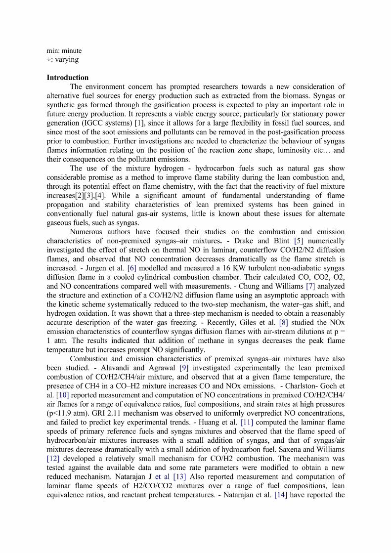
min: minute÷: varying
IntroductionThe environment concern has prompted researchers towards a new consideration of
alternative fuel sources for energy production such as extracted from the biomass. Syngas or synthetic gas formed through the gasification process is expected to play an important role in future energy production. It represents a viable energy source, particularly for stationary power generation (IGCC systems) [1], since it allows for a large flexibility in fossil fuel sources, and since most of the soot emissions and pollutants can be removed in the post-gasification process prior to combustion. Further investigations are needed to characterize the behaviour of syngas flames information relating on the position of the reaction zone shape, luminosity etc… and their consequences on the pollutant emissions.
The use of the mixture hydrogen - hydrocarbon fuels such as natural gas show considerable promise as a method to improve flame stability during the lean combustion and, through its potential effect on flame chemistry, with the fact that the reactivity of fuel mixture increases[2][3],[4]. While a significant amount of fundamental understanding of flame propagation and stability characteristics of lean premixed systems has been gained in conventionally fuel natural gas-air systems, little is known about these issues for alternate gaseous fuels, such as syngas.
Numerous authors have focused their studies on the combustion and emission characteristics of non-premixed syngas–air mixtures. - Drake and Blint [5] numerically investigated the effect of stretch on thermal NO in laminar, counterflow CO/H2/N2 diffusion flames, and observed that NO concentration decreases dramatically as the flame stretch is increased. - Jurgen et al. [6] modelled and measured a 16 KW turbulent non-adiabatic syngas diffusion flame in a cooled cylindrical combustion chamber. Their calculated CO, CO2, O2, and NO concentrations compared well with measurements. - Chung and Williams [7] analyzed the structure and extinction of a CO/H2/N2 diffusion flame using an asymptotic approach with the kinetic scheme systematically reduced to the two-step mechanism, the water–gas shift, and hydrogen oxidation. It was shown that a three-step mechanism is needed to obtain a reasonably accurate description of the water–gas freezing. - Recently, Giles et al. [8] studied the NOx emission characteristics of counterflow syngas diffusion flames with air-stream dilutions at p = 1 atm. The results indicated that addition of methane in syngas decreases the peak flame temperature but increases prompt NO significantly.
Combustion and emission characteristics of premixed syngas–air mixtures have also been studied. - Alavandi and Agrawal [9] investigated experimentally the lean premixed combustion of CO/H2/CH4/air mixture, and observed that at a given flame temperature, the presence of CH4 in a CO–H2 mixture increases CO and NOx emissions. - Charlston- Goch et al. [10] reported measurement and computation of NO concentrations in premixed CO/H2/CH4/air flames for a range of equivalence ratios, fuel compositions, and strain rates at high pressures (p<11.9 atm). GRI 2.11 mechanism was observed to uniformly overpredict NO concentrations, and failed to predict key experimental trends. - Huang et al. [11] computed the laminar flame speeds of primary reference fuels and syngas mixtures and observed that the flame speed of hydrocarbon/air mixtures increases with a small addition of syngas, and that of syngas/air mixtures decrease dramatically with a small addition of hydrocarbon fuel. Saxena and Williams [12] developed a relatively small mechanism for CO/H2 combustion. The mechanism was tested against the available data and some rate parameters were modified to obtain a new reduced mechanism. Natarajan J et al [13] Also reported measurement and computation of laminar flame speeds of H2/CO/CO2 mixtures over a range of fuel compositions, lean equivalence ratios, and reactant preheat temperatures. - Natarajan et al. [14] have reported the
effects of syngas addition on the laminar flame speeds and flammability limits of n-butane and iso-butane flames.
This paper deals with preliminary investigation and highlights the need for experimental investigation of syngas flames in order to provide well-characterized measurements that can be used for the development and validation of simulation models, and extrapolate the present results in a turbulent non-premixed swirling reactor similar to many industrial combustion systems to gas turbines applications.
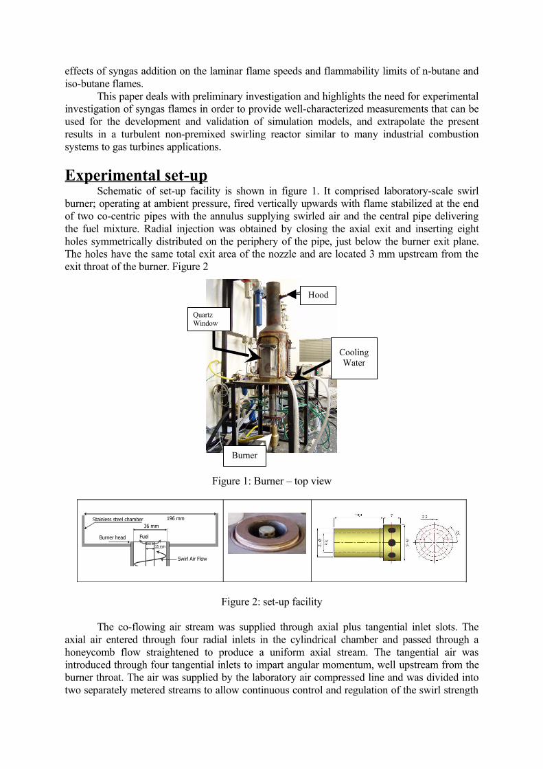
Experimental set-upSchematic of set-up facility is shown in figure 1. It comprised laboratory-scale swirl
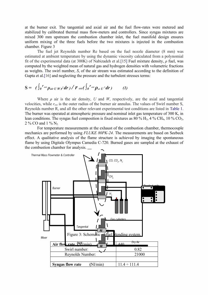
burner; operating at ambient pressure, fired vertically upwards with flame stabilized at the end of two co-centric pipes with the annulus supplying swirled air and the central pipe delivering the fuel mixture. Radial injection was obtained by closing the axial exit and inserting eight holes symmetrically distributed on the periphery of the pipe, just below the burner exit plane. The holes have the same total exit area of the nozzle and are located 3 mm upstream from the exit throat of the burner. Figure 2
Figure 1: Burner – top view
15 mm
Swirl Air Flow
Fuel
36 mm 196 mm Stainless steel chamber
Burner head
Figure 2: set-up facility
The co-flowing air stream was supplied through axial plus tangential inlet slots. The axial air entered through four radial inlets in the cylindrical chamber and passed through a honeycomb flow straightened to produce a uniform axial stream. The tangential air was introduced through four tangential inlets to impart angular momentum, well upstream from the burner throat. The air was supplied by the laboratory air compressed line and was divided into two separately metered streams to allow continuous control and regulation of the swirl strength
Quartz Window
Burner
Cooling Water
Hood
at the burner exit. The tangential and axial air and the fuel flow-rates were metered and stabilized by calibrated thermal mass flow-meters and controllers. Since syngas mixtures are mixed 300 mm upstream the combustion chamber inlet, the fuel manifold design ensures uniform mixing of the three fuels before the two mixtures is injected in the combustion chamber. Figure 3
The fuel jet Reynolds number Re based on the fuel nozzle diameter (8 mm) was estimated at ambient temperature by using the dynamic viscosity calculated from a polynomial fit of the experimental data (at 300K) of Nabizadeh et al.[15] Fuel mixture density, ρ fuel, was computed by the weighted mean of natural gas and hydrogen densities with volumetric fractions as weights. The swirl number, S, of the air stream was estimated according to the definition of Gupta et al.[16] and neglecting the pressure and the turbulent stresses terms:
S = ( ∫0 r ext ρair U W r2 dr ) / r ext ( ∫0
r ext ρair U 2 dr ) (1)
Where ρ air is the air density, U and W, respectively, are the axial and tangential velocities, while rext is the outer radius of the burner air annulus. The values of Swirl number S, Reynolds number R, and all the other relevant experimental test conditions are listed in Table 1. The burner was operated at atmospheric pressure and nominal inlet gas temperature of 300 K, in lean conditions. The syngas fuel composition is fixed mixtures as 80 % H2, 4 % CH4, 10 % CO2, 2 % CO and 1 % N2.
For temperature measurements at the exhaust of the combustion chamber, thermocouple mechanics are performed by using FLUKE 80PK-24. The measurements are based on Seebeck effect. A qualitative analysis of the flame structure is achieved by imaging the spontaneous flame by using Digitale Olympus Camedia C-720. Burned gases are sampled at the exhaust of the combustion chamber for analysis.
Figure 3: Schematic of fuel blending system.
Air flow rate (Nl/min) 440 Swirl number: 0.82 Reynolds Number: 21000
Syngas flow rate (Nl/min) 11.4 ÷ 111.4
Mixer
H2
CH4
CO, CO2, N
2
Burner1 12 l/m2 21 l/
AI
AIDry AirAxial
Tangential
Thermal Mass Flowmeter & Controller
Readout units
Gas cylinders
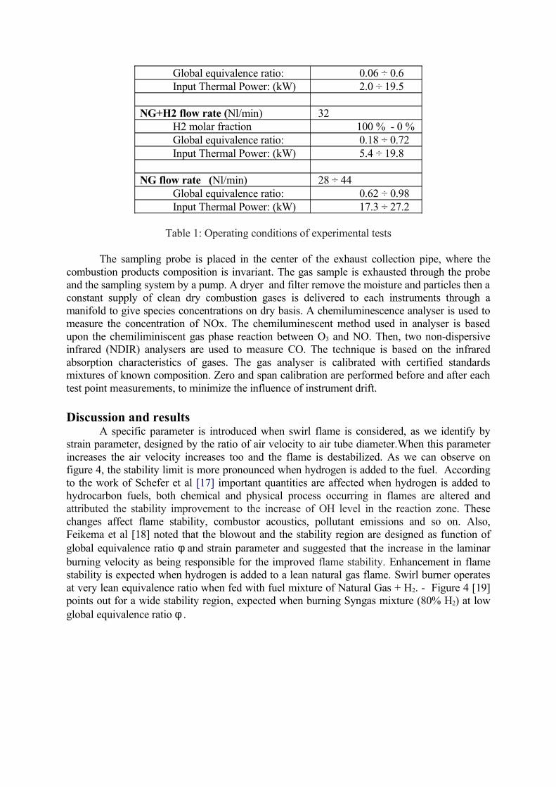
Global equivalence ratio: 0.06 ÷ 0.6 Input Thermal Power: (kW) 2.0 ÷ 19.5
NG+H2 flow rate (Nl/min) 32 H2 molar fraction 100 % - 0 % Global equivalence ratio: 0.18 ÷ 0.72 Input Thermal Power: (kW) 5.4 ÷ 19.8
NG flow rate (Nl/min) 28 ÷ 44 Global equivalence ratio: 0.62 ÷ 0.98 Input Thermal Power: (kW) 17.3 ÷ 27.2
Table 1: Operating conditions of experimental tests
The sampling probe is placed in the center of the exhaust collection pipe, where the combustion products composition is invariant. The gas sample is exhausted through the probe and the sampling system by a pump. A dryer and filter remove the moisture and particles then a constant supply of clean dry combustion gases is delivered to each instruments through a manifold to give species concentrations on dry basis. A chemiluminescence analyser is used to measure the concentration of NOx. The chemiluminescent method used in analyser is based upon the chemiliminiscent gas phase reaction between O3 and NO. Then, two non-dispersive infrared (NDIR) analysers are used to measure CO. The technique is based on the infrared absorption characteristics of gases. The gas analyser is calibrated with certified standards mixtures of known composition. Zero and span calibration are performed before and after each test point measurements, to minimize the influence of instrument drift.
Discussion and resultsA specific parameter is introduced when swirl flame is considered, as we identify by
strain parameter, designed by the ratio of air velocity to air tube diameter.When this parameter increases the air velocity increases too and the flame is destabilized. As we can observe on figure 4, the stability limit is more pronounced when hydrogen is added to the fuel. According to the work of Schefer et al [17] important quantities are affected when hydrogen is added to hydrocarbon fuels, both chemical and physical process occurring in flames are altered and attributed the stability improvement to the increase of OH level in the reaction zone. These changes affect flame stability, combustor acoustics, pollutant emissions and so on. Also, Feikema et al [18] noted that the blowout and the stability region are designed as function of global equivalence ratio φ and strain parameter and suggested that the increase in the laminar burning velocity as being responsible for the improved flame stability. Enhancement in flame stability is expected when hydrogen is added to a lean natural gas flame. Swirl burner operates at very lean equivalence ratio when fed with fuel mixture of Natural Gas + H2. - Figure 4 [19] points out for a wide stability region, expected when burning Syngas mixture (80% H2) at low global equivalence ratio φ .
Ugello radiale 8 fori
0
0.1
0.2
0.3
0.4
0.5
0.6
0.7
90 130 170 210 250 290 330 370 410 450 490 530Ua/Da [1/s]
Ph
i g
lob
ale
0% H210% H2
30% H2
Glo
bal é
quiv
alen
ce
rati
o Φ
Strain parameter, Uair
/dburner
, 1/s
Stable
Blowout
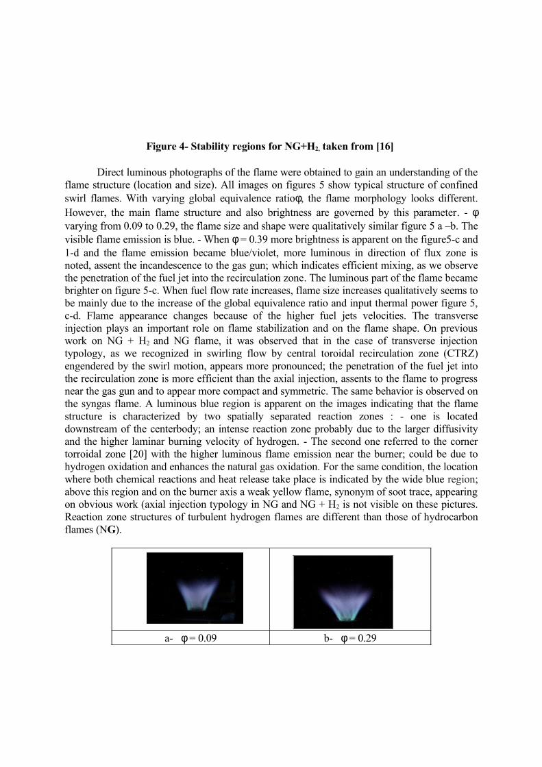
Figure 4- Stability regions for NG+H2, taken from [16]
Direct luminous photographs of the flame were obtained to gain an understanding of the flame structure (location and size). All images on figures 5 show typical structure of confined swirl flames. With varying global equivalence ratioφ, the flame morphology looks different. However, the main flame structure and also brightness are governed by this parameter. - φ varying from 0.09 to 0.29, the flame size and shape were qualitatively similar figure 5 a –b. The visible flame emission is blue. - When φ = 0.39 more brightness is apparent on the figure5-c and 1-d and the flame emission became blue/violet, more luminous in direction of flux zone is noted, assent the incandescence to the gas gun; which indicates efficient mixing, as we observe the penetration of the fuel jet into the recirculation zone. The luminous part of the flame became brighter on figure 5-c. When fuel flow rate increases, flame size increases qualitatively seems to be mainly due to the increase of the global equivalence ratio and input thermal power figure 5, c-d. Flame appearance changes because of the higher fuel jets velocities. The transverse injection plays an important role on flame stabilization and on the flame shape. On previous work on NG + H2 and NG flame, it was observed that in the case of transverse injection typology, as we recognized in swirling flow by central toroidal recirculation zone (CTRZ) engendered by the swirl motion, appears more pronounced; the penetration of the fuel jet into the recirculation zone is more efficient than the axial injection, assents to the flame to progress near the gas gun and to appear more compact and symmetric. The same behavior is observed on the syngas flame. A luminous blue region is apparent on the images indicating that the flame structure is characterized by two spatially separated reaction zones : - one is located downstream of the centerbody; an intense reaction zone probably due to the larger diffusivity and the higher laminar burning velocity of hydrogen. - The second one referred to the corner torroidal zone [20] with the higher luminous flame emission near the burner; could be due to hydrogen oxidation and enhances the natural gas oxidation. For the same condition, the location where both chemical reactions and heat release take place is indicated by the wide blue region; above this region and on the burner axis a weak yellow flame, synonym of soot trace, appearing on obvious work (axial injection typology in NG and NG + H2 is not visible on these pictures. Reaction zone structures of turbulent hydrogen flames are different than those of hydrocarbon flames (NG).
a- φ = 0.09 b- φ = 0.29
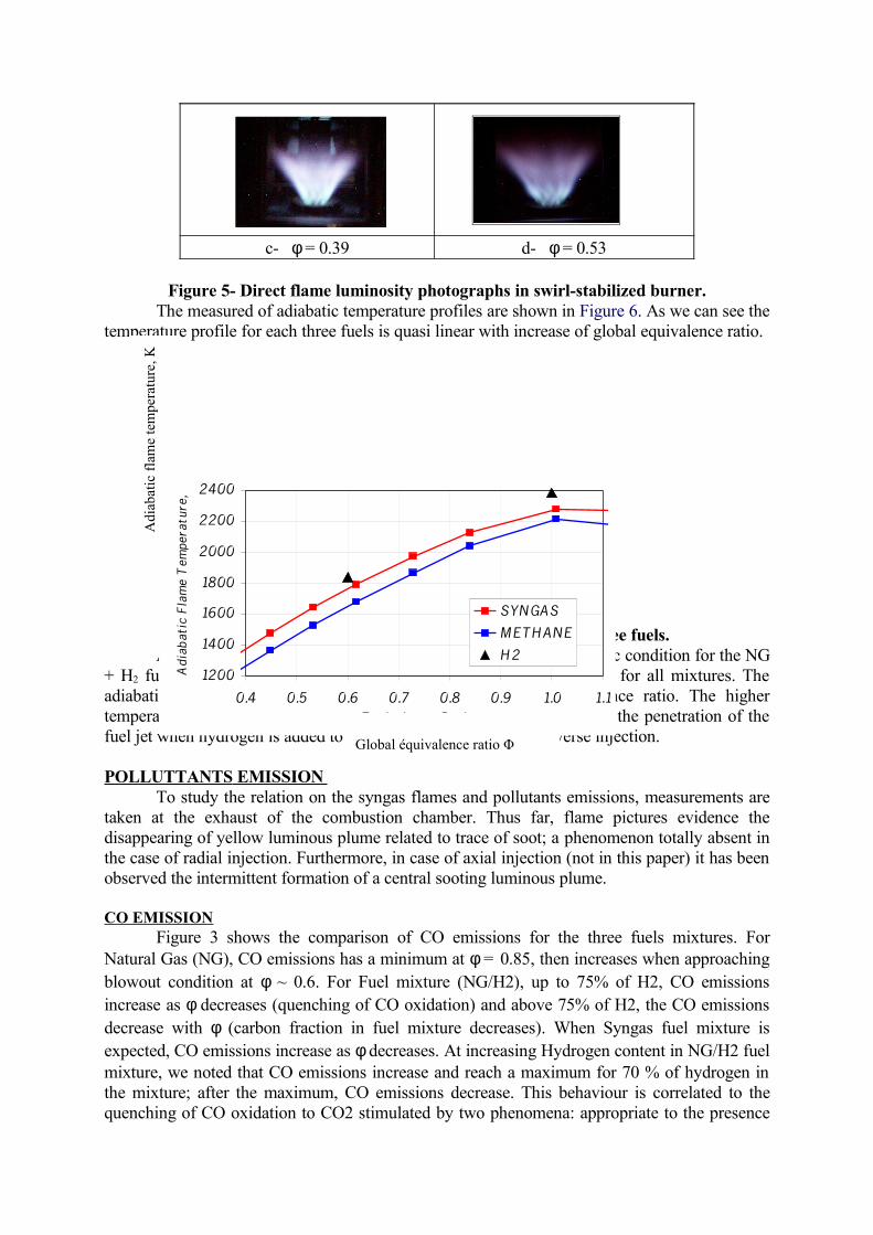
c- φ = 0.39 d- φ = 0.53
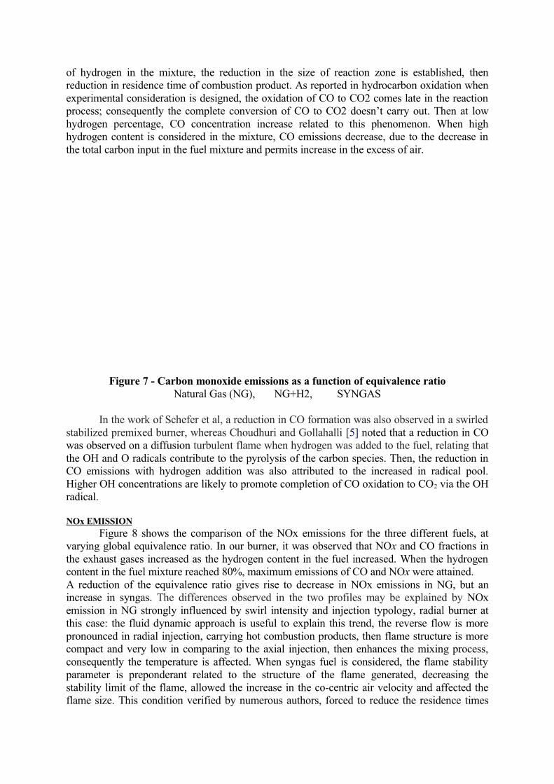
Figure 5- Direct flame luminosity photographs in swirl-stabilized burner.The measured of adiabatic temperature profiles are shown in Figure 6. As we can see the
temperature profile for each three fuels is quasi linear with increase of global equivalence ratio.
Figure 6- Measured of adiabatic temperature of the three fuels.A peak temperature is clearly visible in the profile at stochiometric condition for the NG
+ H2 fuels. The results generally revealed a rapid temperature increase for all mixtures. The adiabatic temperature profiles are strongly affected by the equivalence ratio. The higher temperature is attributed to the hydrogen fuels and can be associated to the penetration of the fuel jet when hydrogen is added to the mixture combined to transverse injection.
POLLUTTANTS EMISSION To study the relation on the syngas flames and pollutants emissions, measurements are
taken at the exhaust of the combustion chamber. Thus far, flame pictures evidence the disappearing of yellow luminous plume related to trace of soot; a phenomenon totally absent in the case of radial injection. Furthermore, in case of axial injection (not in this paper) it has been observed the intermittent formation of a central sooting luminous plume.
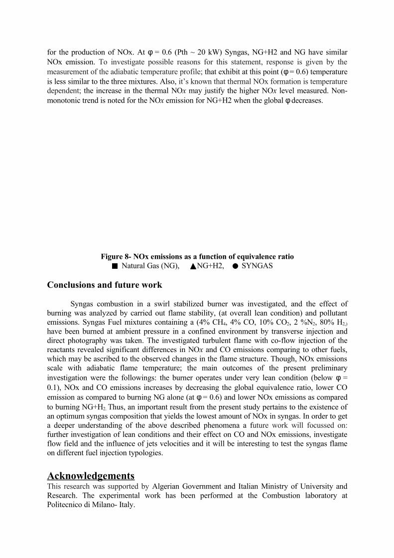
CO EMISSIONFigure 3 shows the comparison of CO emissions for the three fuels mixtures. For
Natural Gas (NG), CO emissions has a minimum at φ = 0.85, then increases when approaching blowout condition at φ ~ 0.6. For Fuel mixture (NG/H2), up to 75% of H2, CO emissions increase as φ decreases (quenching of CO oxidation) and above 75% of H2, the CO emissions decrease with φ (carbon fraction in fuel mixture decreases). When Syngas fuel mixture is expected, CO emissions increase as φ decreases. At increasing Hydrogen content in NG/H2 fuel mixture, we noted that CO emissions increase and reach a maximum for 70 % of hydrogen in the mixture; after the maximum, CO emissions decrease. This behaviour is correlated to the quenching of CO oxidation to CO2 stimulated by two phenomena: appropriate to the presence
1200
1400
1600
1800
2000
2200
2400
0.4 0.5 0.6 0.7 0.8 0.9 1.0 1.1Equivalence Rat io, φ
Adi
abat
ic F
lam
e T
empe
ratu
re, K
SYN GAS
M ET H AN E
H 2
Global équivalence ratio Φ
Adi
abat
ic f
lam
e te
mpe
ratu
re, K
of hydrogen in the mixture, the reduction in the size of reaction zone is established, then reduction in residence time of combustion product. As reported in hydrocarbon oxidation when experimental consideration is designed, the oxidation of CO to CO2 comes late in the reaction process; consequently the complete conversion of CO to CO2 doesn’t carry out. Then at low hydrogen percentage, CO concentration increase related to this phenomenon. When high hydrogen content is considered in the mixture, CO emissions decrease, due to the decrease in the total carbon input in the fuel mixture and permits increase in the excess of air.
Figure 7 - Carbon monoxide emissions as a function of equivalence ratioNatural Gas (NG), NG+H2, SYNGAS
In the work of Schefer et al, a reduction in CO formation was also observed in a swirled stabilized premixed burner, whereas Choudhuri and Gollahalli [5] noted that a reduction in CO was observed on a diffusion turbulent flame when hydrogen was added to the fuel, relating that the OH and O radicals contribute to the pyrolysis of the carbon species. Then, the reduction in CO emissions with hydrogen addition was also attributed to the increased in radical pool. Higher OH concentrations are likely to promote completion of CO oxidation to CO2 via the OH radical.
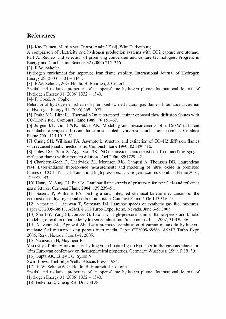
NOx EMISSIONFigure 8 shows the comparison of the NOx emissions for the three different fuels, at
varying global equivalence ratio. In our burner, it was observed that NOx and CO fractions in the exhaust gases increased as the hydrogen content in the fuel increased. When the hydrogen content in the fuel mixture reached 80%, maximum emissions of CO and NOx were attained. A reduction of the equivalence ratio gives rise to decrease in NOx emissions in NG, but an increase in syngas. The differences observed in the two profiles may be explained by NOx emission in NG strongly influenced by swirl intensity and injection typology, radial burner at this case: the fluid dynamic approach is useful to explain this trend, the reverse flow is more pronounced in radial injection, carrying hot combustion products, then flame structure is more compact and very low in comparing to the axial injection, then enhances the mixing process, consequently the temperature is affected. When syngas fuel is considered, the flame stability parameter is preponderant related to the structure of the flame generated, decreasing the stability limit of the flame, allowed the increase in the co-centric air velocity and affected the flame size. This condition verified by numerous authors, forced to reduce the residence times
0
500
1000
1500
2000
2500
0.0 0.2 0.4 0.6 0.8 1.0Global Equivalence Rat io, φ
CO
mg/N
m3 3%
O 2
0
10
20
30
40
50
60
70
80
90
100
0 % H 2100% H 2
75 % H 2
50 % H 2
87.5 % H 2
CO
mg/
Nm
3 3%
O2
Global equivalence ratio φ
for the production of NOx. At φ = 0.6 (Pth ~ 20 kW) Syngas, NG+H2 and NG have similar NOx emission. To investigate possible reasons for this statement, response is given by the measurement of the adiabatic temperature profile; that exhibit at this point (φ = 0.6) temperature is less similar to the three mixtures. Also, it’s known that thermal NOx formation is temperature dependent; the increase in the thermal NOx may justify the higher NOx level measured. Non-monotonic trend is noted for the NOx emission for NG+H2 when the global φ decreases.
Figure 8- NOx emissions as a function of equivalence ratioNatural Gas (NG), NG+H2, SYNGAS
Conclusions and future work
Syngas combustion in a swirl stabilized burner was investigated, and the effect of burning was analyzed by carried out flame stability, (at overall lean condition) and pollutant emissions. Syngas Fuel mixtures containing a (4% CH4, 4% CO, 10% CO2, 2 %N2, 80% H2,)
have been burned at ambient pressure in a confined environment by transverse injection and direct photography was taken. The investigated turbulent flame with co-flow injection of the reactants revealed significant differences in NOx and CO emissions comparing to other fuels, which may be ascribed to the observed changes in the flame structure. Though, NOx emissions scale with adiabatic flame temperature; the main outcomes of the present preliminary investigation were the followings: the burner operates under very lean condition (below φ = 0.1), NOx and CO emissions increases by decreasing the global equivalence ratio, lower CO emission as compared to burning NG alone (at φ = 0.6) and lower NOx emissions as compared to burning NG+H2. Thus, an important result from the present study pertains to the existence of an optimum syngas composition that yields the lowest amount of NOx in syngas. In order to get a deeper understanding of the above described phenomena a future work will focussed on: further investigation of lean conditions and their effect on CO and NOx emissions, investigate flow field and the influence of jets velocities and it will be interesting to test the syngas flame on different fuel injection typologies.
AcknowledgementsThis research was supported by Algerian Government and Italian Ministry of University and Research. The experimental work has been performed at the Combustion laboratory at Politecnico di Milano- Italy.
0
20
40
60
80
100
120
140
0 0.2 0.4 0.6 0.8 1Global equivalence r at io, φ
NO
x m
g/N
m3 3%
O2
0 % H 2
100% H 2
75 % H 2
50 % H 2
NO
x m
g/N
m3%
O2
Global equivalence ratio Φ
References
[1]- Kay Damen, Martijn van Troost, Andre´ Faaij, Wim TurkenburgA comparison of electricity and hydrogen production systems with CO2 capture and storage. Part A: Review and selection of promising conversion and capture technologies. Progress in Energy and Combustion Science 32 (2006) 215–246. [2]- R.W. ScheferHydrogen enrichment for improved lean flame stability. International Journal of Hydrogen Energy 28 (2003) 1131 – 1141.[3]- R.W. Schefer,W.G. Houfa, B. Bourneb, J. Coltonb Spatial and radiative properties of an open-flame hydrogen plume. International Journal of Hydrogen Energy 31 (2006) 1332 – 1340.[4]- F. Cozzi, A. CogheBehavior of hydrogen-enriched non-premixed swirled natural gas flames. International Journal of Hydrogen Energy 31 (2006) 669 – 677. [5] Drake MC, Blint RJ. Thermal NOx in stretched laminar opposed flow diffusion flames with CO/H2/N2 fuel. Combust Flame 1989; 76:151–67.[6] Jurgen JJL, Jim BWK, Sikke AK. Modeling and measurements of a 16-kW turbulent nonadiabatic syngas diffusion flame in a cooled cylindrical combustion chamber. Combust Flame 2001;125:1012–31.[7] Chung SH, Williams FA. Asymptotic structure and extinction of CO–H2 diffusion flames with reduced kinetic mechanisms. Combust Flame 1990; 82:389–410.[8] Giles DG, Som S, Aggarwal SK. NOx emission characteristics of counterflow syngas diffusion flames with airstream dilution. Fuel 2006; 85:1729–42.[9] Charlston-Goch D, Chadwick BL, Morrison RJS, Campisi A, Thomsen DD, Laurendeau NM. Laser-induced fluorescence measurements and modeling of nitric oxide in premixed flames of CO + H2 + CH4 and air at high pressures: I. Nitrogen fixation. Combust Flame 2001; 125:729–43.[10] Huang Y, Sung CJ, Eng JA. Laminar flame speeds of primary reference fuels and reformer gas mixtures. Combust Flame 2004; 139:239–51.[11] Saxena P, Williams FA. Testing a small detailed chemical-kinetic mechanism for the combustion of hydrogen and carbon monoxide. Combust Flame 2006;145:316–23.[12] Natarajan J, Lieuwen T, Seitzman JM. Laminar speeds of synthetic gas fuel mixtures. Paper GT2005-68917. ASME-IGTI Turbo Expo, Reno, Nevada, June 6–9, 2005.[13] Sun HY, Yang SI, Jomaas G, Law CK. High-pressure laminar flame speeds and kinetic modeling of carbon monoxide/hydrogen combustion. Proc combust Inst. 2007; 31:439–46[14] Alavandi SK, Agrawal AK. Lean premixed combustion of carbon monoxide–hydrogen–methane fuel mixtures using porous inert media. Paper GT2005-68586. ASME Turbo Expo 2005. Reno, Nevada, June 6–9, 2005.[15] Nabizadeh H, Mayinger F. Viscosity of binary mixtures of hydrogen and natural gas (Hythane) in the gaseous phase. In: 15th European conference on thermophysical properties. Germany: Würzburg; 1999. P.19–30. [16] Gupta AK, Lilley DG, Syred N. Swirl flows. Tunbridge Wells: Abacus Press; 1984.[17]- R.W. ScheferW.G. Houfa, B. Bourneb, J. Coltonb Spatial and radiative properties of an open-flame hydrogen plume. International Journal of Hydrogen Energy 31 (2006) 1332 – 1340.[18] Feikema D, Cheng RH, Driscoll JF.

Blowout of nonpremixed flames: maximum coaxial air velocities achievable, with and without swirl. Combust Flame 1991; 86:347–58. [19] Andrea Olivani, Giulio Solero, Fabio Cozzi, Aldo Coghe Near field flow structure of isothermal swirling flows and reacting non-premixed swirling flames. Experimental 4thMediterranean Combustion Symposium, Lisbon, 2005.[20]- David R. Noble, Qingguo Zhang, Akbar Shareef, Jeremiah Tootle, Andrew Meyers, Tim Lieuwen. Syngas Mixture Composition Effects upon Flaschback and Blowout. Proceedings of GT2006 ASME Turbo Expo 2006: Power for Land, Sea and Air May 8-11, 2006, Barcelona, Spain.