Embed Size (px)
Citation preview
584 TRANSFORMATION DE PHASE DANS LE FLUOSILICATE DE FER
orientations B pour une orientation A. Toutefois le groupe d'espace (P3) auquel nous sommes conduit ne permet pas de d~crire compl&ement la structure qui doit &re regardre comme une antiphase p~riodique orientationnelle se produisant dans la phase ordonn~e de basse temperature (P21/c). Les fronti~res d'anti- phase moyennes n'rtant jamais strictement perpen- diculaires ~ la direction d'antiphase, les fronti~res rrelles ne peuvent plus &re considrrres comme planes, ce qui pourrait se v~rifier exp~rimentalement en microscopie fi haute r~solution. Ces irr~gularit~s de fronti+res qui sont fi l'origine de la rupture de p~riodicitb suivant c hexagonal (Fig. 4) pourraient avoir un caract+re dynamique. Des mesures de dif- fusion inrlastique de neutrons ont +t+ entreprises pour essayer de prrciser ce point. Quoi qu'il en soit, il restera
s'interroger sur les conditions d'apparition de telles structures, aucune explication ne pouvant &re avancre
l'heure actuelle.
R6f~rences
CHEVRIER, G. & JISHANNO, G. (1979). Acta Cryst. A35, 912-916.
HAMILTON, W. (1962). Acta Cryst. 15, 353-360. J~HANNO, G. & VARRET, F. (1975). Acta Cryst. A31,
857-858. KODERA, E., TORRI, A., OSAKI, K. & WATANASE, T. (1972).
J. Phys. Soc. Jpn, 32, 863. OHTSUBO, A. (1965). J. Phys. Soc. Jpn, 20, 82-88. RAY, S. (1972). Symposium on Crystallography, Bombay. RAY, S., ZALKIN, A. & TEMPLETON, D. H. (1973). Acta
Cryst. B29, 2741-2747. SYOYAMA, S. & OSAKI, K. (1972). Acta Cryst. B28,
2626-2627. TOURNARIE, M. (1969). J. Phys. 10, 737. VOLLAND, U., HOSL, S., SPIERING, H., D~ZSl, I., KEMI~NY,
T. & NAGY, D. L. (1978). Solid State Commun. 27, 49-51.
WATANABE, D. t~ TAKASHIMA, K. (1975). J. Appl. Cryst. 8, 598-602.
Acta Cryst. (1981). A37, 584-593
Extinction, Polarization and Crystal Monochromators
BY L. D. JENNINGS
Army Research Center, Watertown, MA 02172, USA
(Received 17 September 1980;
Abstract
A number of theories are examined for their predictions of extinction coefficients at large values of extinction, especially as applied to polarization ratios. Although several theories give the behavior expected on the basis of physical reasoning (a polarization ratio approaching unity), the popular theories of Zachariasen [Acta Cryst. (1967), 23, 558-564] and Becker & Coppens [Acta Cryst. (1964), A30, 129-147, 148-153] do not show the correct asymptotic behavior. Although this short- coming may be of no consequence in ordinary crystallographic applications, it is misleading in predict- ing the correct polarization factor to be used in connection with a crystal-monochromated apparatus, where the monochromator is usually adjusted to maximize its extinction. The importance of measuring, rather than estimating, the polarization ratio of a crystal monochromator is therefore re-emphasized.
1. Introduction
Crystallographers and others who make use of X-ray (or neutron) diffraction for practical problems require
accepted 9 February 1981)
working formulas to relate measured intensities to structure factors. These formulas contain some para- meters which are known a priori, some measured parameters and, typically, other parameters which are determined by a least-squares fit. One of the para- meters is the polarization ratio of the X-ray beam, the ratio of the power with polarization in the plane of diffraction to that with perpendicular polarization. Another parameter, or set of parameters, characterizes the physical state of the sample; these are the extinction parameters. Because of the importance of these parameters in an accurate assessment of the data, there has been a fair amount of research in recent years into the appropriate use of extinction parameters. Unfortunately there has not been equal attention paid to the use of correct polarization ratios in the case of crystal monochromated radiation. As a matter of fact, the application of complete extinction theory to the properties of crystal monochromators shows that the expected value of the polarization ratio in a crystal- monochromatized experiment is far from the value usually quoted and must almost always be considered a parameter which is not known a priori. The purpose of this paper is to document that statement and to show
L. D. JENNINGS 585
Table 1. Nomenclature
Wavelength and Bragg angle are denoted by 2 and 0. The other symbols used are defined in connection with the indicated equations.
A (18) Q (12) y (6) p (3) E (39) Q' (34) Ys (21) a (19) K (1) R (1) 6 (4) r (16) Kp (3) S (17) e (2) q~ (19) K~ (4) t (29) ~ (29) oJ (13)
u
m (8) T (24) r/ (23) If (1) P (19) x (24) A (11) l (1)
X (25) U (11)
some qualitative shortcomings of the most used extinction theories.
Before getting involved with equations and cal- culations, it is well to consider a physical picture of the situation. 'Extinction' is used to describe a condition in which the incident beam is significantly reduced by diffraction processes. The concept may be made quantitative through the extinction coefficient y, which is the factor by which the integrated reflection is reduced compared to the value for an ideally mosaic sample. (Table 1 gives a reference to the precise definition of each symbol.) In crystallography it is usual to endeavor to reduce the extinction in the sample as much as possible, making y as near unity as possible. The reason for this is that it is then easiest to get a valid relationship between measured intensities and structure factors. This does not mean, however, that all aspects of a well designed diffraction experiment are free of extinction. In particular, if a crystal monochromator is used, it is advantageous that it diffract the desired radiation as strongly as possible. That is to say, it is desirable (in many cases) to design a monochromator to give the maximum possible extinction.
This extinction has a profound effect on the polarization ratio of a crystal monochromated beam. Consider an unpolarized beam incident on an ideally mosaic (i.e. extinction free) monochromator. In this case the polarization ratio is m 2 ---- c o s 2 20 m, where 0 m is the Bragg angle of the monochromator. On the other hand, a well designed monochromator will display so much extinction that the desired rays of both polarizations are almost totally diffracted. The polarization ratio is thus approximately unity. This result has been known for some time (Jennings, 1968). It is, however, often overlooked in crystallographic applications. For example, in their widely quoted paper emphasizing the importance of extinction, Becker & Coppens (1974b) give explicit formulas which assume, without comment, that the crystal monochromator is extinction free.
2. Statement of problem
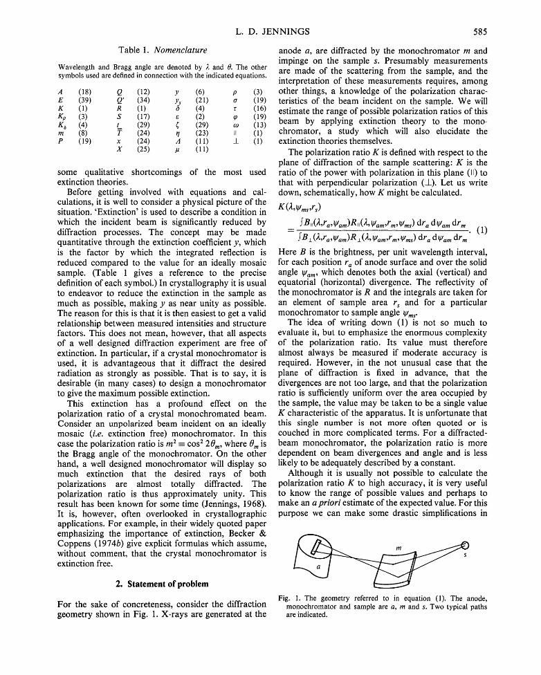
For the sake of concreteness, consider the diffraction geometry shown in Fig. 1. X-rays are generated at the
anode a, are diffracted by the monochromator m and impinge on the sample s. Presumably measurements are made of the scattering from the sample, and the interpretation of these measurements requires, among other things, a knowledge of the polarization charac- teristics of the beam incident on the sample. We will estimate the range of possible polarization ratios of this beam by applying extinction theory to the mono- chromator, a study which will also elucidate the extinction theories themselves.
The polarization ratio K is defined with respect to the plane of diffraction of the sample scattering: K is the ratio of the power with polarization in this plane (11) to that with perpendicular polarization (_L). Let us write down, schematically, how K might be calculated.
K (~,,v/ms,rs)
f B,, (2,ra, v/am)R ,, ( ~,, v/am,rm, v/ms) dra d V/am drm = (1)
f B ± (2,r,,, v/am)R ± ( 2 , v/am,rm, v/ms) dra d v/am drm "
Here B is the brightness, per unit wavelength interval, for each position r a of anode surface and over the solid angle V/am, which denotes both the axial (vertical) and equatorial (horizontal) divergence. The reflectivity of the monochromator is R and the integrals are taken for an element of sample area r s and for a particular monochromator to sample angle V/ms"
The idea of writing down (1) is not so much to evaluate it, but to emphasize the enormous complexity of the polarization ratio. Its value must therefore almost always be measured if moderate accuracy is required. However, in the not unusual case that the plane of diffraction is fixed in advance, that the divergences are not too large, and that the polarization ratio is sufficiently uniform over the area occupied by the sample, the value may be taken to be a single value K characteristic of the apparatus. It is unfortunate that this single number is not more often quoted or is couched in more complicated terms. For a diffracted- beam monochromator, the polarization ratio is more dependent on beam divergences and angle and is less likely to be adequately described by a constant.
Although it is usually not possible to calculate the polarization ratio K to high accuracy, it is very useful to know the range of possible values and perhaps to make an a priori estimate of the expected value. For this purpose we can make some drastic simplifications in
Fig. 1. The geometry referred to in equation (1). The anode, monochromator and sample are a, m and s. Two typical paths are indicated.
586 EXTINCTION, POLARIZATION AND CRYSTAL MONOCHROMATORS
(1). Consider a small portion of the monochromator surface over which its properties may be assumed uniform. Neglect the effects of axial divergence and of wavelength distribution (presumably the interest is in a single spectral line). Assume further that it is adequate to consider the polarization ratio of the entire beam and that the source is uniform and unpolarized. Then (1) can be written
fB(~)R,(c) dc K = fB(e)Rl (e ) de" (2)
Here e is the equatorial angle from a point on the monochromator to a point on the anode, conveniently measured from the peak of the reflectivity curve. To be even more definite, it is useful to consider two cases. At one extreme, the illuminated anode is so broad that B(e) has its (constant) value for all e for which R is appreciable. In this case, the numerator and denomi- nator in (2) are proportional to the integrated reflection p = f P de for each polarization state. (Recall that here, and in most of the rest of the paper, we will be thinking of the monochromator as the 'sample', i.e. we will be applying extinction theory to the monochromator.) We may then write
gp = P,,/Pt. (3)
At the other extreme, the anode spot may be narrow compared to the rocking curve R(e), in which case B(e) is effectively a ~ function. Then
K~(c) = R,,(e)/R ±(e). (4)
K~ has been called a polarization coefficient by Olekhnovich & Markovich (1978). In a practical case, for maximum monochromated power, the situation is likely to be intermediate between the cases represented by (3) and (4).
Even the very general equation (1) glosses over a number of important physical considerations. Many questions of coherence, discussed in the papers of Kato (1976a,b), Hart (1978) and Dmitrienko & Belyakov (1980), are ignored. One such question is the dis- tinction between the integrated reflection in (3) deter- mined by placing a fixed crystal in an incident spherical wave and that determined by rotating a crystal through an incident plane wave. The distinction is discussed by Kato (1976a) and Becker (1977b) and is of some importance in a number of experiments. For routine work with imperfect crystals it is generally assumed that the two evaluations of integrated reflection are effectively equal, and we shall use either one in connection with (3).
In the case of nearly perfect crystals, the peak of the reflectivity curve may come at a slightly different angle for the II and the _1_ components. This difference, in principle, causes conceptual difficulties with the position of e -- 0 in (4). The angle involved, however, is
of the order of a second of arc and is not of consequence in practical applications.
It is possible to set up situations where the polarization ratio is known or irrelevant. The use of polarizing monochromators is discussed by Hart & Rodrigues (1979), Hart (1978), Mitra & Samantaray (1975), Chandrasekhar, Ramaseshan & Singh (1969), Olekhnovich (1969b) and Olekhnovich & Markovich (1978).
The formula for the polarization factor to be applied to the sample reflection has been given in many places (e.g. Mathieson, 1978; Staun Olsen, Buras, Jensen, Alstrup, Gerward & Selsmark, 1978; Olekhnovich, 1969a; Azaroff, 1955). I fK 1 is the polarization ratio of the incident beam (referred to its principal axes), K2 the polarization ratio of the sample (referred to its principal axes) and Z a rotation angle defined in the references, then the polarization factor is given by
[ cos2 Z + KI sin 2 Z + K2( sin2 Z + K~ cos 2 ,~)]/(1 + K1).
(5)
It is immediately clear that this expression is inde- pendent of K~ for Z = 45 o, and in this case gives the same result as obtains for an unpolarized beam. [It should be cautioned that the beam is not actually unpolarized and that (5) is not complete in case coherence effects are important; cf. Hart (1978); Annaka, Suzuki & Onoue (1980). Some authors prefer a coherent separation, e.g. Alcock (1974).] Although it has been suggested that apparatus be constructed with Z = 45 o (Mathieson, 1978; Staun Olsen et al., 1978), most workers have preferred the simpler arrangements with Z = 0 or 90 o. The former, with the two diffraction planes parallel, is referred to as 'normal geometry' by Kerr & Ashmore (1974) and is the case we will use for illustration. Thus we will consider the situation with K -- g p
3. Extinction theory
Our objective is to make estimates of K based on (3) and (4) and on available extinction theories. It is therefore useful to add to and summarize the review of Becker (1977a), giving the most recent papers where references to earlier work are listed. There have been several attempts at alternative formulation which have not, up to now, led to practical equations (Balibar & Malgrange, 1975; Kuriyama, 1975). Some calculations have been carried through to practical form, but have stated limitations on sample perfection, sample form, etc., e.g. Sears (1977), Olekhnovich & Olekhnovich (1978, 1980), Werner (1974), Wilkins (1980), Boeuf, Lagomarsino, Mazkedian, Melone, Puliti & Rustichelli (1978) and Brown & Fatemi (1974). There are also limitations on the formulation of Kato (1976a, 1976b, 1979, 1980), but, since this work uses a distinctive
L. D. JENNINGS 587
sample model and is also carried through to practical equations, it deserves special mention. Extinction theory has also been examined by authors whose primary interest was the elimination of extinction, e.g. Seiler & Dunitz (1978) and Schneider, Hansen & Kretschmer (1981).
In spite of all this work, the formulations preferred by far by crystallographers are those of Zachariasen (1967) and of others who use a similar rationale. As we shall see, this preference is probably based more on the fact that these results are in a form immediately applicable to least-squares programs than to a cor- rectness of the physical models (Zachariasen, 1969).
To illustrate this remark, we may use the extinction coefficients
y± = p±/pid, (6a)
y ,f = p,,/p,Ja, (6b)
whence, from (3), the polarization ratio is
Kp = m 2 y,,/y ± (7)
with
m -- I cos 201. (8)
Here pia is the integrated reflection for an ideal mosaic and 0 is the Bragg angle for the monochromator (again being considered as the sample). Zachariasen's theory gives the extinction coefficients directly yielding
y± = (1 + 2 X z ) -1/2, (9)
Kp = m2[(1 + 2Xz)/(1 + 2 m 2 X z ) l u2, (10)
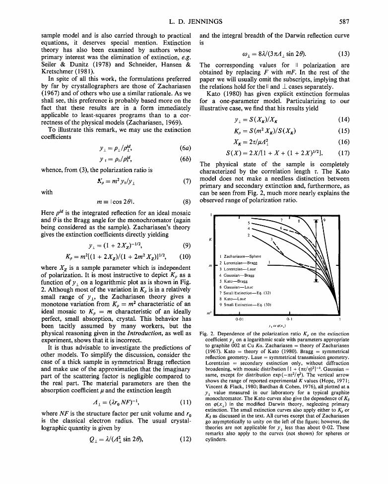
where X z is a sample parameter which is independent of polarization. It is most instructive to depict Kp as a function of y± on a logarithmic plot as is shown in Fig. 2. Although most of the variation in Kp is in a relatively small range of y±, the Zachariasen theory gives a monotone variation from Kp = m 2 characteristic of an ideal mosaic to Kp = m characteristic of an ideally perfect, small absorption, crystal. This behavior has been tacitly assumed by many workers, but the physical reasoning given in the Introduction, as well as experiment, shows that it is incorrect.
It is thus advisable to investigate the predictions of other models. To simplify the discussion, consider the case of a thick sample in symmetrical Bragg reflection and make use of the approximation that the imaginary part of the scattering factor is negligible compared to the real part. The material parameters are then the absorption coefficient # and the extinction length
A± = (2r 0 N F ) -1, (11)
where N F is the structure factor per unit volume and r o is the classical electron radius. The usual crystal- lographic quantity is given by
Q± = 2 / (A 2 sin 20), (12)
and the integral breadth of the Darwin reflection curve is
co I = 82/(3zcA l sin 20). (13)
The corresponding values for II polarization are obtained by replacing F with mF. In the rest of the paper we will usually omit the subscripts, implying that the relations hold for the II and I cases separately.
Kato (1980) has given explicit extinction formulas for a one-parameter model. Particularizing to our illustrative case, we find that his results yield
y± = S ( X x ) / X ~ (14)
Kp = S ( m 2 X r ) / S ( X K ) (15)
X K = 2r /#A z (16)
S ( X ) = 2X/[1 + X + (1 + 2X)1/2]. (17)
The physical state of the sample is completely characterized by the correlation length r. The Kato model does not make a needless distinction between primary and secondary extinction and, furthermore, as can be seen from Fig. 2, much more nearly explains the observed range of polarization ratio.
rr/2
\
I Zachariasen--Sphere ~
2 Lorentzian--Bragg I . "~
3 Lorentzian--Laue
4 Gaussian--Bragg
5 Kato--Bragg
6 Gaussian--Laue
7 Small Extinction--Eq. (32)
8 Kato--Laue
9 Small Extinction--Eq. (30)
I 0-01 0.1
y~ or ¢(x~)
Fig. 2. Dependence of the polarization ratio Kp on the extinction coefficient y± on a logarithmic scale with parameters appropriate to graphite 002 at Cu Ka. Zachariasen = theory of Zachariasen (1967). Kato = theory of Kato (1980). Bragg = symmetrical reflection geometry. Laue = symmetrical transmission geometry. Lorentzian = secondary extinction only, without diffraction broadening, with mosaic distribution [ 1 + (z~e/r/)2]-L Gaussian = same, except for distribution exp(-zce2/r/2). The vertical arrow shows the range of reported experimental K values (Hope, 1971; Vincent & Flack, 1980; Bardhan & Cohen, 1976), all plotted at a y± value measured in our laboratory for a typical graphite monochromator. The Kato curves also give the dependence of K6 on ~0(x±) in the modified Darwin theory, neglecting primary extinction. The small extinction curves also apply either to Kp or K6 as discussed in the text. All curves except that of Zachariasen go asymptotically to unity on the left of the figure; however, the theories are not applicable for y± less than about 0.02. These remarks also apply to the curves (not shown) for spheres or cylinders.
588 EXTIN C TIO N , P O L A R I Z A T I O N AND CRYSTAL M O N O C H R O M A T O R S
In spite of its advantages, the Kato model is incomplete. It does not address polarization coefficients and requires that r be small compared to A. It may also not have the flexibility to represent the average behavior of non-uniform samples as well as do other (no more correct) theories. It is therefore useful to consider yet additional models, for which we first give some general background.
4. Secondary extinction
Almost all theories except that of Kato distinguish between primary and secondary extinction. The former refers to effects which depend explicitly on A, the latter to cases where any A dependence is implicit or lacking. In the event that primary extinction and diffraction broadening of the beam may be neglected, it is possible to solve (perhaps numerically) the transfer equations (Hamilton, 1957; Werner, Arrott, King & Kendrick, 1966). The solution is conveniently given in two stages. Firstly, consider a collimated beam from which the sample area S O intercepts a power P0. Anticipating the application to large extinction, we find it is convenient to use the transmission factor in the form
A = f exp [-~t(t 1 + t2)] d V / S o. (18)
Then we define
(0(o) = P / ( P o A e ) = P/Pk, (19)
where o is the macroscopic scattering cross section per unit volume, P is the actual diffracted power and Pk is the extinction-free value. Within the assumptions the polarization coefficient may be written
K s = o, ~0(o,,)/[o± ~0(oz)]. (20)
The polarization ratio (equations 6 and 7) may be given in terms of the secondary extinction coefficient
y s = Q -1 f aq)(e) de, (21)
where we have used the result that in the absence of primary extinction
f o d e = a. (22)
Furthermore, it is convenient to characterize the function a(e) through its (extinction free) integral breadth r/so that
a ( e = o) = a/rl. (23)
We also use the parameters
x = aT (24)
and
X = Xma x = QT/rl, ( 2 5 )
with T = - (dA/dlu) /A, the average path length. Then,
to first order, q) = 1 - x + ... and the polarization ratio is determined through the relation X~, = m2X±.
It is useful to give a few examples to clarify the correct asymptoti_c behavior of ~0. For symmetrical Bragg reflection, T = 2A = l /a , independent of angle. The transfer equations (James, 1948; Zachariasen, 1945) yield
(on = 2/11 + x + (1 + 2x)1/2]. ( ~ ) /
Although the function in (26) is essentially the same ~s that in (17), it should be borne in mind that the former applies to an integrated reflection and the latter to a reflectivity. For large x, where there is nearly tot~tl reflection in Bragg geometry, we have the asymptoti:c relation ~o n ~ 2/x, as could be determined directly from (19) since P/Po ~ 1. The values of y depend on the form of a(e). Choosing a simple rectangular function so that y = ~0 (Hamilton, 1957), we have for large X, y ~ 2 / X = 21art~Q, showing that the integrated reflection p = yQA is asymptotically equal to r/, independent of Q. The same results are approximately true for other mosaic distributions, though the asymptotic behavior for y would not be approached so rapidly as for ~0.
The case of a cylinder of diameter Dc with its axis normal to the beam has been solved by Hamilton (1957, 1963), verifying the following results, which can also be obtained by physical reasoning. We illustrate this with the case of negligible absorption. Then A = rcDc/4 and T = 8Dc/3~z. For 2 0 = 180 ° we have Bragg geometry so the sample is totally reflecting for large x yielding ¢p~(180 °) ~ 1/o,4 = 32/3n a x. Because there is always a small portion of the cylinder that is not totally reflecting, the asymptotic condition is not achieved as rapidly as for the thick plate, but all the above discussion applies. For 20 = 0 °, at large x values the beam splits into equal forward diffracted and dif- fracted beams yielding ~0~(0 °) ~ 1/2aA = 16/377 x. For intermediate 20 values, the results are intermediate showing that the asymptotic integrated reflection (for the case y = ~0) lies between r /and r//2, depending on 20, but independent of Q.
The results for a sphere of diameter Ds can be obtained from those for a cylinder by breaking the sphere into a number of elementary cylinders and integrating. We have
1
(Os(aDs)=~f ~oc (aDc) (1 -~ )d~ (27) 0
aDc = aDs( 1 _ ~ 2 ) 1 / 2 (28)
with a similar formula for y. In case absorption is negligible we have A = 2Ds/3 and T - - - 3Ds/4. Although the asymptotic values would be approached even less rapidly than in the case of a cylinder, all the remarks about large-x behavior still apply.
These examples have been given to correct erroneous statements in the literature and to show that the
L. D. JENNINGS 589
situation does not depend in a fundamental way on sample shape or diffraction angle. It is simplest to consider cases for which ~0 depends only on x and for which y depends only on X. The functional dependence of the results is emphasized by calculating the polarization ratios as is shown in Fig. 2. The polarization coefficient for these secondary extinction examples, plotted against the natural parameter ~0(x±), happens to be identical to the Kato result for integrated reflection and is, of course, somewhat higher than the polarization ratio based on the same model.
5. Small extinction formalism
As is apparent from the Kato formulation, there is little need to distinguish primary from secondary extinction in case the extinction is small. This point had already been made by Chandrasekhar (1956), who realized that, to first order, all extinction theories yield
y = 1 - ~Q + . . . , (29)
where ~ is a parameter of the order of T/r/ for secondary extinction and of the order t2/2 for primary extinction, with t being the path length within a coherent domain, ff may depend somewhat on sample shape, diffracting angle, details of mosaic distribution, etc., but not on polarization. Taking cognizance of the relation Q,, = m 2 Ql, it is easy to show that
K29-=mEy,,/y_L=m 2 [m 2 + (1--m2)/y±], (30)
where the subscript indicates the assumption of (29). This result is plotted in Fig. 2. It is seen that the behavior near y± = 1 is correct, but that (30) cannot obtain for smaller y±. However, to the order carried, we could as well replace (29) with
y = 1/(1 + CQ) + . . . , (31)
in which case we obtain
K31 -----= m2/[m 2 + (1 -- m2)y_L], (32)
which gives results comparable to those of Kato or of the secondary extinction calculations.
This entire formalism obtains equally well for q~ instead of y. So the small extinction plots of Fig. 2 can also be considered as the expansion of K a as a function of~0(xl).
6. More complete formulations
The formulations discussed so far have limitations on their applicability. For example, the Kato theory is restricted to moderate correlation lengths and to divergent beams; the secondary extinction calculations assume negligible diffraction broadening; etc. Further-
more, these theories use a single parameter (at least in so far as polarization is concerned) to characterize the physical state of the sample. Actual samples may be much more complicated. Most of the ideas which have been used to deal with these complications can be included in a modified Darwin theory, which we now outline.
One considers a small region of ideally perfect material. The solution of the diffraction equations for such perfect platelets has been known for years (Zachariasen, 1945; James, 1948). If we neglect the distinction between the Ewald and the Darwin solution, the integrated reflection for Bragg geometry is
p = Q' t (33)
with
Q' = Q tanh (t/A)/(t/A). (34)
For Laue geometry, Pendell6sung effects lead to an oscillatory dependence of p on t/A, but the average behavior may be approximated adequately for the present purposes by an ad hoc function such as
Q ' = (Q/2)ttanh (t/A)/(t/A) + exp(-t2/3A2)l, (35)
which is chosen to have the correct initial behavior and also agrees with the result that beam splitting causes the large t asymptote to be only ½ that of the Bragg case (as is also true for secondary extinction). The solution for small perfect cylinders (Olekhnovich & Olekhnovich, 1980) is similar to the Bragg case at high angle and shows muted Pendelldsung at low angle. Thus (34) and (35) approximate the limiting behavior for Q', with the former favored at high 20 and the latter at low 20. Turning one's attention to the macroscopic sample, one then assumes that T is large compared to t and that the beam divergence is large compared to o) and thus that primary extinction can be corrected by replacing Q by Q' in (23) for the cross section, and elsewhere, as in (25).
The assumption of small diffracting regions implies particle-size broadening. Such broadening was well known to the early workers who explicitly did not consider cases where it is important. More recently (Kuznetsov, 1962; Zachariasen, 1967; Becker & Coppens, 1974a,b) it has become the custom to convolute this broadening with the true mosaic spread, though no justification for this procedure has been given and it has been severely criticized by Werner (1974). It seems to us that the convolution would be approximately valid for cases where extinction arises primarily from a single diffraction event, but would underestimate the broadening when many orders of multiple scattering occur. In any case, some estimate is usually better than none, so one assumes a particle size broadening 22/t sin 20. If the true mosaic spread has a
590 E X T I N C T I O N , P O L A R I Z A T I O N A N D C R Y S T A L M O N O C H R O M A T O R S
breadth %, we may indicate the value to be used in (23) by
rl = % • (22/t sin 20), (36)
where t h e , represents a combination appropriate to the assumed convolution function, for example, adding the two terms in quadrature.
Lastly, one may consider the range of validity of the formula implied by all this reasoning,
Po = O' Ays(Q' T/q). (37)
This result is plausible so long as t < T and r /> co. In other cases there would be the implication that fewer than one mosaic block is contributing to the dif- fraction, a clear contradiction. So, for Bragg geometry, we can write an ad hoe formula to ensure that p never goes below its value co for a single ideally perfect crystal:
p~___. (p2 -k- (./)2) 1/2. ( 38 )
For the transmission case, 09 would be replaced by o9/2. Implementation of (38) depends on the choice of t, r/,
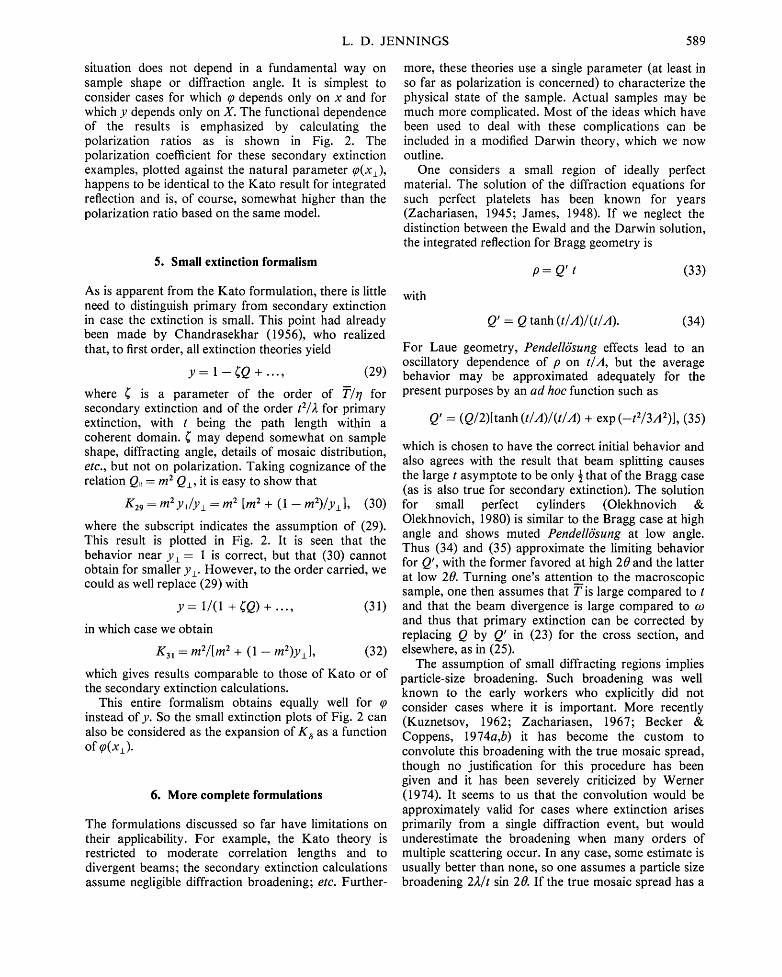
the form of the convoluted broadening function, and of the macroscopic extinction function Ys. Because real crystals so rarely have a smooth, uniform mosaic character (Schneider, 1977; Lehman & Schneider, 1977; Schneider, Hansen & Kretschmer, 1981), there seems little point in being fastidious about these choices. However, we believe that calculations, based on some possible, though perhaps unrealistic, model are useful in indicating the qualitative features of the results. Fig. 3 shows the range of K values obtained by assuming a Gaussian broadening function, ys based on (26), and Q' of (34). The lower part of the range is determined by primary extinction and the upper part is a combination of primary and secondary extinction. The left-hand portion shows the approach to ideally perfect single-crystal behavior at a value of y = E, where E is the ratio of the kinematic to the dynamical integrated reflection, given by
E = 16 pA/3zc. (39)
To be more specific, Fig. 3 also shows curves based on a 'dislocation model' (Olekhnovich & Markovich, 1978) of a reasonable behavior for a real material. For this model we chose % = 22/t sin z 0, yielding a single parameter curve.
Fig. 3 also indicates the increased range encom- passed by replacing (34) with (35) and/or (26) with ~0~ = [1 - exp ( - 2 x ) ] / 2 x appropriate to symmetrical transmission. In addition, the effect of assuming a Lorentziarl distribution is shown in Fig. 3. The decreased proportion of the sample showing strong extinction is evident, but the limiting behavior corres- ponds to the physical discussion given previously.
7. Experimental situation
There have been numerous proposals to use the polarization ratio to characterize crystal perfection, to assist in accurate determination of extinction-free structure factors, and to characterize diffraction ap- paratus. By contrast, very few data are available; even recent papers whose sole purpose is to characterize a monochromator have failed to give its polarization ratio. We have therefore only indicated the range of published values for graphite at Cu Ka in Fig. 2; in no case was the corresponding integrated reflection reported.
Although they have not explicitly discussed polari- zation ratios, the Harwell group have made a number of investigations of heavily extinguished reflections (e.g. Cooper & Rouse, 1970, 1976; Sakata, Cooper, Rouse & Willis, 1978). These workers have developed expressions which meet the requirements of (29) and
] I I
K~
K
/11
,,,~ I I 0.01 0-I
y~ or (Q'I/Q±)~o(X'~)
Fig. 3. The range of polarization ratios Kp (shown by the vertical hatched region) allowed by the modified Darwin calculation for graphite at Cu Ka (m = 0.894) in symmetrical reflection geometry with a Gaussian mosaic distribution. Note that the theory allows a very wide range where the values are greater than m = I cos 201, but converges on the left side of the figure to the correct value m at y± = E±. The solid curve shows the values of Kp predicted for a sample following the 'dislocation model'. The right-hand and upper horizontal hatched region shows that the deviation from ideally mosaic behavior is even more pronounced for transmission geometry with respect to primary and/or secondary extinction. The left-hand horizontal hatched region shows that the assumption of a Lorentzian mosaic distribution does not qualitatively change the behavior, though it does increase the fraction of the reflection curve for which extinction effects are not severe. The results also do not depend strongly on m for m > ½ (Jennings, 1968). The upper curve is Ka vs (Q'/Q)(o(Q'/21arl) for the dislocation model in symmetrical reflection. The factor Q'/Q is required so that the reference condition is one that is free of both primary and secondary extinction. The ad hoe assumptions made do not apply as well to Ka as to Kp, and the curve for the former does not necessarily give a good representation of the situation where both the 11 and _1_ reflectivities can approach unity for an (unrealistically) well collimated beam incident on an ideally perfect sample.
L. D. JENNINGS 591
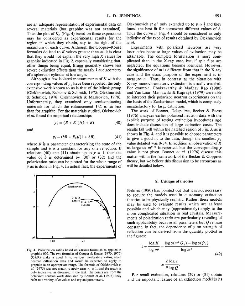
are an adequate representation of experimental data on several materials (but graphite was not examined). Thus the plot of Kp (Fig. 4) based on these expressions may be considered as experimental results for the region in which they obtain, say to the right of the maximum of each curve. Although the Cooper-Rouse formulas do lead to K values greater than m, it is clear that they would not explain the very high K values for graphite indicated in Fig. 2, especially considering that, other things being equal, Bragg geometry shows less severe extinction effects than the nearly Laue geometry of a sphere or cylinder at low angle.
Although a few isolated measurements of K with the corresponding values of y± have been reported, the only extensive work known to us is that of the Minsk group (Olekhnovich, Rubtsov & Schmidt, 1975; Olekhnovich & Schmidt, 1976; Olekhnovich & Markovich, 1978). Unfortunately, they examined only semiconducting materials for which the enhancement 1 /E is far less than for graphite. For the materials studied, Oleknovich et al. found the empirical relationships
y± = (B + E±)/(1 + B) (40)
and
y,, = (bB + E,,)/(1 + bB), (41)
where B is a parameter characterizing the state of the sample and b is a constant for any one reflection. If relations (40) and (41) obtain up to y = 1, then the value of b is determined by (30) or (32) and the polarization ratio can be plotted for the whole range of y as is done in Fig. 4. In actual fact, the experiments of
Olekhnovich et al. only extended up to y _~ ½ and they found the best fit for somewhat different values of b. Thus the curve in Fig. 4 should be considered as only indictive of the type of results obtained by Olekhnovich et al.
Experiments with polarized neutrons are very instructive because large values of extinction may be attainable. The complete formulation is more com- plicated than in the X-ray case, but, if spin flips are neglected, the equations become identical• However, the significance of m is different from that in the X-ray case and the usual purpose of the experiment is to measure m. Thus, in contrast to the situation with X-ray monochromators, extinction is usually avoided. For example, Chakravarthy & Madhav Rao (1980) and Van Laar, Maniawski & Kaprzyk (1979)were able to interpret their polarized neutron experiments on the the basis of the Zachariasen model, which is completely unsatisfactory for large extinction•
The work of Bonnet, Delapalme, Becker & Fuess (1976) analyzes earlier polarized neutron data with the explicit purpose of testing extinction hypotheses and does include discussion of large extinction cases. The results fall well within the hatched region of Fig. 3, as is shown in Fig. 4, and it is possible to choose parameters to give a good fit to the data, though the smallest yz value detailed was 0- 34. In addition an observation of K as large as m °'53 is reported, but the corresponding y value is not given. Bonnet et al. (1976) discuss this matter within the framework of the Becker & Coppens theory, but we believe this discussion to be erroneous as will be detailed below.
In
l / l 2
0.01 0.1 1
Y±
Fig. 4. Polarization ratios based on various formulas as applied to graphite 002. The two formulas of Cooper & Rouse (1970, 1976) (C&R) make a good fit to various moderately extinguished neutron diffraction data and would be expected to apply to graphite in an appropriate range. The formula of Olekhnovich et al. (1975) was not meant to apply near y± _~ 1, and the graph is only indicative, as discussed in the text. The points are from the polarized neutron work discussed by Bonnet et al. (1976); they refer to a variety ofm values and crystal parameters.
8. Critique of theories
Nelmes (1980) has pointed out that it is not necessary to require the models used in customary extinction theories to be physically realistic. Rather, these models may be used to evaluate results which are at least possible and which may (approximately) apply to the more complicated situation in real crystals. Measure- ments of polarization ratio are particularly revealing of such applicability because all parameters but Q remain constant. In fact, the dependence of y on strength of reflection can be derived from the quantity plotted in the figures:
log K log y ( m 2 Q l ) - log y ( Q ± )
log m 2 log m 2
8 log y
c3 log Q
(42)
For small extinction, relations (29) or (31) obtain and the important feature of an extinction model is its
592 EXTINCTION, POLARIZATION AND CRYSTAL MONOCHROMATORS
prediction about the angular and sample-shape depen- dence of the coefficient ¢. The theory of Zachariasen (1967), which attributes primary extinction to a path t and secondary extinction to a path T - t, yields (for a fixed ;I,) a simple one-parameter, angularly independent model. The theory of Olekhnovich, Markovich & Oleknovich (1980) gives a sin 20 dependence for ¢. Other theories may specify an intermediate angular dependence or may invoke additional parameters, allowing more complex behavior. Often, however, the data are not adequate to define such additional parameters, and only the limiting cases of ¢ indepen- dent of angle (type I) or ¢ proportional to sin 20 (type II) are considered. In any case, the most appropriate analysis of small extinction is still a matter of controversy which we will not discuss further.
For large extinction, the Zachariasen theory cannot explain the observed polarization ratios, though many of the other theories presented, including that of Kato, do yield physically plausible results. The Becker & Coppens (B&C) theory requires more complete dis- cussion. In their original presentation, which gives the explicit formulas usually used, B&C (1974a,b) sug- gested an unconventional separation of primary and secondary extinction. This separation is clearly incor- rect for large extinction. Perhaps for this reason, B&C (1975) suggested using the conventional separation of (37). In any event, B&C use an analytic approxi- mation to the secondary extinction coefficient which is a good fit at low to moderate extinction and suggests an X -1/2 behavior at large extinction. Stephan & L6schau (1976a,b, 1978) have come to a similar conclusion. Such behavior would lead to a limiting polarization ratio of m 1/2, as accepted by Bonnet et al. (1976). However, the physical reasoning given above (or calculation) shows that for reasonable mosaic distri- butions the secondary extinction coefficient goes approximately as 1/7( for large X. Thus one can understand the failure of the B&C theory to explain the large extinction cases discussed by Hutton, Nelmes & Scheel (1981) or the polarization ratios of high- efficiency monochromators.
It would go beyond the scope of this paper to discuss the theories in more detail. We will only note that the distinction among the various theories, in so far as crystallographic applications are concerned, is pri- marily in the moderate extinction region. It would seem that, even for the moderate extinction region, a theory such as the modified Darwin theory, making use of correct secondary extinction calculations, would be preferable, at least conceptually, to those theories which yield an incorrect large extinction result. Unfor- tunately, those theories which do yield correct limiting behavior have not been cast in a form convenient for a least-squares fit. It is presumably for this reason that t, he more approximate theories of Zachariasen and Becker & Coppens have been so widely used. In any
case, it is extremely unlikely that any current theory will be more than a very rough approximation to the complex physical state of an actual monochromator or sample.
9. Summary and recommendations
A crystal monochromator designed to reflect a single X-ray spectral line as strongly as possible will show strong extinction. We have compared the available experimental results on polarization ratios of such monochromators with a large number of extinction theories, emphasizing qualitative and physical aspects. These comparisons show that some of the theories and the bulk of the experimental results are plausible at large extinction, yielding a limiting value near unity for the polarization ratio. The discussion shows that the popular theories of Zachariasen (1967) and Becker & Coppens (1974), although giving a good first and second approximation to the situation at low to moderate extinction, may not be extrapolated correctly to large extinction.
Because of the complex physical state of a typical monochromator, it is unrealistic to attempt to calcu- late its polarization ratio on the basis of any of the theories; the purpose of the comparisons mentioned above is solely to give a qualitative picture of the situation. Therefore it is particularly important to measure the polarization ratio of any crystal mono- chromator as part of the routine of setting up a diffraction apparatus (if a correct polarization factor is required in the use of the apparatus). Furthermore, as a service to other diffractionists, I would urge that these measured values be communicated to me as a part of the IUCr survey of polarization ratios (International Union of Crystallography, 19 78).
I thank David Chipman for discussion and encouragement and Richard Nelmes for correspondence.
References
ALCOCK, N. W. (1974). Acta Cryst. A30, 332-335. ANNAKA, S., SUZUKI, T. & ONOUE, K. (1980). Acta Cryst.
A36, 151-152. AZAROFF, L. V. (1955). Acta Cryst. 8, 701-704. BALIBAR, F. & MALGRANGE, C. (1975). Acta Cryst. A31,
425-434. BARDHAN, P. & COHEN, J. B. (1976). Acta Cryst. A32,
597-614. BECKER, P. (1977a). Acta Cryst. A33, 243-249. BECKER, P. (1977b). Acta Cryst. A33, 667-671. BECKER, P. J. & COPPENS, P. (1974a). Acta Cryst. A30,
129-147. BECKER, P. J. & COPPENS, P. (1974b). Acta Cryst. A30,
148-153.
L. D. J E N N I N G S 593
BECKER, P. J. & COPPENS, P. (1975). Acta Cryst. A31, 417-425.
BOEUF, A., LAGOMARSINO, S., MAZKEDIAN, S., MELONE, S., PULITI, P. & RUSTICHELLI, F. (1978). J. Appl. Cryst. II, 442-449.
BONNET, M., DELAPALME, A., BECKER, P. & FUESS, H. (1976). Acta Cryst. A32, 945-953.
BROWN, D. B. & FATEMI, M. (1974). J. Appl. Phys. 45, 1544-1554.
CHAKRAVARTHY, R. & MADHAV RAO, L. (1980). Acta Cryst. A36, 139-142.
CHANDRASEKHAR, S. (1956). Acta Cryst. 9, 954-955. CHANDRASEKHAR, S., RAMASESHAN, S. & SINGH, A. K.
(1969). Acta Cryst. A25, 140-142. COOPER, M. J. & ROUSE, K. D. (1970). Acta Cryst. A24,
214-223. COOPER, M. J. & ROUSE, K. D. (1976). Acta Cryst. A32,
806-812. DMITRIENKO, V. E. & BELYAKOV, V. A. (1980). Acta Cryst.
A36, 1044-1050. HAMILTON, W. C. (1957). Acta Cryst. 10, 629-634. HAMILTON, W. C. (1963). Acta Cryst. 16, 609-611. HART, M. (1978). Philos. Mag. B38, 41-56. HART, M. & RODRIGUES, A. R. D. (1979). Philos. Mag.
B40, 149-157. HOPE, H. (1971). Acta Cryst. A27, 392-393. HUTTON, J., NELMES, R. J. & SCHEEL, H. J. (1981). To be
published. INTERNATIONAL UNION OF CRYSTALLOGRAPHY (1978). A cta
Cryst. A34, 159-160. JAMES, R. W. (1948). The Optical Principles of the
Diffraction of X-rays. London: Bell. JENNINGS, L. D. (1968). Acta Cryst. A24, 472-474. KATO, N. (1976a). Acta Cryst. A32, 453-457. KATO, N. (1976b). Acta Cryst. A32, 458-466. KATO, N. (1979). Acta Cryst. A35, 9-16. KATO, N. (1980). Acta Cryst. A36, 171-177. KERR, K. A. & ASHMORE, J. P. (1974). Acta Cryst. A30,
176-179. KURIYAMA, M. (1975). Acta Cryst. A31, 774-779. KUZNETSOV, A. V. (1962). Kristallografiya, 7, 121-123.
(Soy. Phys. Crystallogr. 7, 97-98.) LEHMANN, M. S. & SCHNEIDER, J. R. (1977). Acta Cryst.
A33, 789-800. MATHIESON, A. McL. (1978). Acta Cryst. A34, 404-406. MITRA, G. I . t~. SAMANTARAY, I . K. (1975). J. Appl. Cryst.
8, 15-16. NELMES, R. J. (1980). Acta Cryst. A36, 641-653.
OLEKHNOVICH, N. M. (1969a). Kristallografiya, 14, 261- 265. (Soy. Phys. Crystallogr. 14, 203-206.)
OLEKHNOVICH, N. M. (1969b). Kristallografiya, 14, 840- 844. (Soy. Phys. Crystallogr. 14, 724-727.)
OLEKHNOVICH, N. M. & MARKOVICH, V. L. (1978). Kristallografiya, 23, 658-661. (Soy. Phys. Crystallogr. 23, 369-370.)
OLEKHNOVICH, N. M., MARKOVICH, V. L. • OLEKHNOVICH, A. I. (1980).Acta Cryst. A36, 989-996.
OLEKHNOVICH, N. M. & OLEKHNOVICH, A. I. (1978). Acta Cryst. A34, 321-326.
OLEKHNOVICH, N. M. & OLEKHNOVICH, A. I. (1980). Acta Cryst. A36, 22-27.
OLEKHNOVICH, N. M., RUaTSOV, V. A. & SCHMIDT, M. P. (1975). Kristallografiya, 20, 796-802. (Soy. Phys. Crystallogr. 20, 488-491).
OLEKHNOVICH, N. M. & SCHMIDT, M. P. (1976). Kristallografiya, 21, 151-156. (Soy. Phys. Crystallogr. 21, 78-81,)
SAKATA, M., COOPER, M. J., ROUSE, K. D. & WILLIS, B. T. M. (1978). Acta Cryst. A34, 336-341.
SCHNEIDER, J. R. (1977). Acta Cryst. A33, 235-243. SCHNEIDER, J. R., HANSEN, N. K. & KRETSCHMER, H.
( 1981). In preparation. SEARS, V. F. (1977).Acta Cryst. A33, 373-381. SELLER, P. & DUNITZ, J. D. (1978). Acta Cryst. A34,
329-336. STAUN OLSEN, J., BURAS, B., JENSEN, T., ALSTRUP, O.,
GERWARD, L. & SELSMARK, B. (1978). Acta Cryst. A34, 84-87.
STEPHAN, D. & LSSCHAU, W. (1976a). Krist. Tech. 11, 1295-1301.
STEPHAN, D. & LOSCHAU, W. (1976b). Krist. Tech. II , 1303-1310.
STEPHAN, D. & LOSCHAU, W. (1978). Krist. Tech. 13, 155-163.
VAN LAAR, l . , MANIAWSKI, F. & KAPRZYK, S. (1979). Acta Cryst. A35,468-475.
VINCENT, M. G. & FLACK, H. D. (1980). Acta Cryst. A36, 614-620.
WERNER, S. A. (1974). J. Appl. Phys. 45, 3246-3254. WERNER, S. A., ARROTT, A., KING, J. S. & KENDRICK, H.
(1966). J. Appl. Phys. 37, 2343-2350. WILKrNS, S. W. (1980). Acta Cryst. A36, 143-146. ZACHARIASEN, W. H. (1945). Theory of X-ray Diffraction in
Crystals. New York: John Wiley. ZACHARIASEN, W. H. (1967). Acta Cryst. 23, 558-564. ZACHARIASEN, W. H. (1969). Acta Cryst. A25, 276.


![CRYSTAL GARANTIES 2011 BAT10ï Mise en page 1 - Net … · 2011-05-05 · [CRYSTAL STUDIES] Crystal Studies, l’assurance complète de vos études à l’étranger ! Crystal Studies](https://img.pdfslide.fr/doc/110x75/5ebc95e11463d476e401c447/crystal-garanties-2011-bat10-mise-en-page-1-net-2011-05-05-crystal-studies.jpg)