Embed Size (px)
Citation preview
Lire et comprendre ce manuel avant de
procéder à l'installation, à des réglages,
de l'entretien ou des réparations.
L'installation de cet appareil doit être
effectuée par un réparateur qualifié.
Toute modification de cet appareil peut
être extrêmement dangereuse et
entraîner des blessures ou dommages
matériels.
USA
SERVICE OFFICE
Dometic Corporation
509 South Poplar Street
Lagrange, IN 46761
260-463-4858
CANADA
Dometic
Distribution 866
Langs Drive
Cambridge, Ontario
CANADA N3H 2N7
519-653-4390
For Service Center
Assistance Call:
800-544-4881
828XXXX, 830XXXX, 833XXXX,
FABRIC ROLLER TUBE TORSION ASSEMBLY
This manual must be read and unT
derstood before installation, add
justment, service, or maintenance
is performed. This unit must be ini
stalled by a qualified service techs
nician. Modification of this product
can be extremely hazardous and
could result in personal injury or
property damage.
SERVI
REVISION
Form No.3105903.060 8/04
(Replaces 3105903.052)
(French 3108577.044)
©2004 Dometic Corporation
LaGrange, IN 46761 1
MODEL 8300 AND SUNCHASER AWNINGS
CE INSTRUCTIONS
MODELS
830(XXXX) 836(XXXX)
828(XXXX) 834(XXXX) 833(XXXX)
SAFETY INSTRUCTIONS
This manual has safety information and instrucT
tions to help users eliminate or reduce the risk of
accidents and injuries.
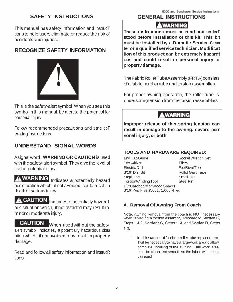
RECOGNIZE SAFETY INFORMATION
TOOLS AND HARDWARE REQUIRED:
End Cap Guide Socket Wrench Set Screwdriver Pliers Electric Drill
3/16" Drill Bit
Stepladder
Pop Rivet Tool
Roll of Gray Tape
Small File Torsion Winding Tool Steel Pin 1/8" Cardboard or Wood Spacer 3/16" Pop Rivet (308171.006) 4 req.
A. Removal Of Awning From Coach
Note: Awning removal from the coach is NOT necessary when replacing a torsion assembly. Proceed to Section B,
Steps 1 & 2, Sections C, Steps 1–3, and Section D, Steps
1–3.
1. In all instances of fabric or roller tube replacement,
it will be necessary to have a large work area to allow
complete unrolling of the awning. This work area
must be clean and smooth so the fabric will not be
damaged.
The Fabric Roller Tube Assembly (FRTA) consists
of a fabric, a roller tube and torsion assemblies.
For proper awning operation, the roller tube is
under spring tension from the torsion assemblies.
Improper release of this spring tension can
result in damage to the awning, severe perr
sonal injury, or both.
These instructions must be read and underT
stood before installation of this kit. This kit
must be installed by a Dometic Service Cenm
ter or a qualified service technician. Modificat
tion of this product can be extremely hazardt
ous and could result in personal injury or
property damage.
!
This is the safety-alert symbol. When you see this
symbol in this manual, be alert to the potential for
personal injury.
Follow recommended precautions and safe opF
erating instructions.
UNDERSTAND SIGNAL WORDS
A signal word , WARNING OR CAUTION is used
with the safety-alert symbol. They give the level of
risk for potential injury.
Indicates a potentially hazard ous situation which, if not avoided, could result in death or serious injury.
Indicates a potentially hazardI
ous situation which, if not avoided may result in
minor or moderate injury.
When used without the safety
alert symbol indicates, a potentially hazardous situa
ation which, if not avoided may result in property
damage.
Read and follow all safety information and instrucR
tions.
2
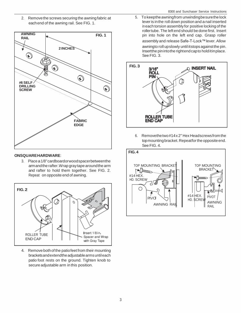
FIG. 1
FIG. 4
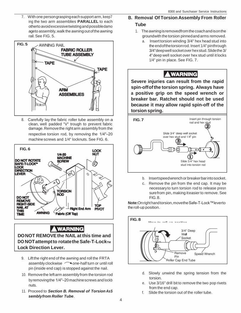
TOP MOUNTING BRACKET
#14 HEX. HD. SCREW
PIVOT
TOP MOUNTING BRACKET
8300 and Sunchaser Service Instructions
2. Remove the screws securing the awning fabric at
each end of the awning rail. See FIG. 1.
AWNING RAIL
2 INCHES
FIG. 3
#6 SELF DRILLING SCREW
FABRIC EDGE
6. Remove the two #14 x 2" Hex Head screws from the
top mounting bracket. Repeat for the opposite end.
See FIG. 4.
ON SQUARE HARDWARE:
3. Place a 1/8" cardboard or wood spacer between the
arm and the rafter. Wrap gray tape around the arm
and rafter to hold them together. See FIG. 2.
Repeat on opposite end of awning.
FIG. 2
#14 HEX. HD. SCREW
AWNING RAIL
ROLLER TUBE END CAP
4. Remove both of the patio feet from their mounting
brackets and extend the adjustable arms until each
patio foot rests on the ground. Tighten knob to
secure adjustable arm in this position.
3
AWNING RAIL
5. To keep the awning from unwinding be sure the lock lever is in the roll down position and a nail inserted in each torsion assembly for positive locking of the roller tube. The left end should be done first. Insert pin into hole on the left end cap. Grasp roller
assembly and release Safe-T-Lock™ lever. Allow
awning to roll up slowly until it stops against the pin. Insert the pin into the right end cap to hold it in place. See FIG. 3.
4
B. Removal Of Torsion Assembly From Roller
Tube
1. The awning is removed from the coach and is on the
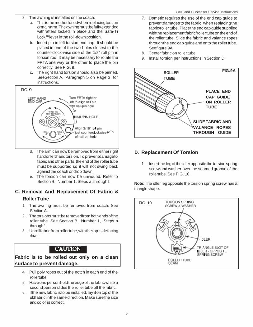
ground with the torsion pinned and arms removed. a. Insert torsion winding 3/4" hex head stud into
the end of the torsion rod. Insert 1/4" pin through
3/4" deep well socket over hex stud. Slide the 3/
4" deep well socket over hex stud until it locks
1/4" pin in place. See FIG. 7.
b. Insert speed wrench or breaker bar into socket.
c. Remove the pin from the end cap. It may be
necessary to turn torsion rod to release presn
sure from pin, making it easier to remove. See
FIG. 8.
Note:On right hand torsion, move the Safe-T-Lock™ lever to the roll-up position.
d. Slowly unwind the spring tension from the
torsion. e. Use 3/16" drill bit to remove the two pop rivets
from the end cap. f. Slide the torsion out of the roller tube.
Severe injuries can result from the rapid
spin-off of the torsion spring. Always have
a positive grip on the speed wrench or
breaker bar. Ratchet should not be used
because it may allow rapid spin-off of the
torsion spring.
FIG. 7
8300 and Sunchaser Service Instructions
7. With one person grasping each support arm, keep7
ing the two arm assemblies PARALLEL to each
other to avoid excessive twisting and possible damo
age to assembly, walk the awning out of the awning
rail. See FIG. 5.
FIG. 5
8. Carefully lay the fabric roller tube assembly on a clean, well padded "V" trough to prevent fabric damage. Remove the right arm assembly from the
respective torsion rod, by removing the 1/4"–20
machine screws and 1/4" locknuts. See FIG. 6.
FIG. 6
FIG. 8
DO NOT REMOVE the NAIL at this time and
DO NOT attempt to rotate the Safe-T-LockTM
Lock Direction Lever.
9. Lift the right end of the awning and roll the FRTA
assembly clockwise one-half turn or until roll
pin (inside end cap) is stopped against the nail.
10. Remove the left arm assembly from the torsion rod
by removing the 1/4"–20 machine screws and lockb
nuts.
11. Proceed to Section B. Removal of Torsion AsS
sembly from Roller Tube.
Move to roll up position
7. Dometic requires the use of the end cap guide to
prevent damages to the fabric, when replacing the
fabric/roller tube. Place the end cap guide supplied
with the replacement fabric/roller tube on the end of
the roller tube. Slide the fabric and valance ropes
through the end cap guide and onto the roller tube.
See figure 9A. 8. Center fabric on roller tube. 9. Install torsion per instructions in Section D.
FIG. 9A
PLACE END
CAP GUIDE ON ROLLER TUBE
ROLLER
TUBE
D. Replacement Of Torsion
1. Insert the leg of the idler opposite the torsion spring
screw and washer over the seamed groove of the
rollertube. See FIG. 10.
Note: The idler leg opposite the torsion spring screw has a
triangle shape.
FIG. 10
8300 and Sunchaser Service Instructions
2. The awning is installed on the coach. a. This is the method used when replacing torsion
or main arm. The awning must be fully extended withrafters locked in place and the Safe-Tr
Lock™ lever in the roll-down position.
b. Insert pin in left torsion end cap. It should be
placed in one of the two holes closest to the
counter-clock-wise side of the 1/8" roll pin in
torsion rod. It may be necessary to rotate the
FRTA one way or the other to place the pin
correctly. See FIG. 9. c. The right hand torsion should also be pinned.
SeeSection A, Paragraph 5 on Page 3, for
instructions.
FIG. 9
SLIDE FABRIC AND
VALANCE ROPES THROUGH GUIDE
d. The arm can now be removed from either right
hand or left hand torsion. To prevent damage to
fabric and other parts, the end of the roller tube
must be supported so it will not swing back
against the coach or drop down. e. The torsion can now be unwound. Refer to
Section B., Number 1, Steps a. through f.
C. Removal And Replacement Of Fabric &
Roller Tube
1. The awning must be removed from coach. See
Section A. 2. The torsions must be removed from both ends of the
roller tube. See Section B., Number 1, Steps a
through f. 3. Unroll fabric from roller tube, with the top-side facing
down.
Fabric is to be rolled out only on a clean
surface to prevent damage.
4. Pull poly ropes out of the notch in each end of the
rollertube. 5. Have one person hold the edge of the fabric while a
second person slides the roller tube off the fabric. 6. If the new fabric is to be installed, lay it on top of the
old fabric in the same direction. Make sure the size
and color is correct.
5

WIND TO ADD TORSION
ROLL DN
ROLL UP ROLL DN
5. Mark the location of rivet holes in the end cap on
rollertube. Drill 3/16" hole. Remove any drill burrs
from inside roller tube. 6. Attach end cap to roller tube with two 3/16" x 3/8"
pop rivets. Repeat on opposite end.
E. Winding Torsions
1. Insert torsion winding tool into torsion rod. See FIG.
7. 2. Always have the speed wrench handle at the 6 O2
clock positions and turn towards the side of the
coach. Left hand end cap is turned clock-wise and
right hand end cap is turned counter-clock-wise to
add tension.
Note: Right hand torsion must have Safe-T-Lock™ lever in
the roll-down position.
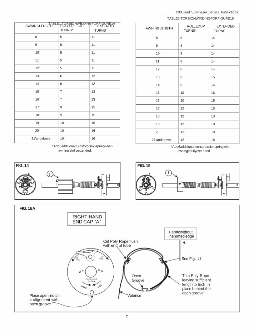
3. After torsion spring is wound to proper number of
turns, insert a steel pin in the end cap to prevent
rapid spin-off when reinstalling on coach. See FIG.
3, page 3 and Table 1 & 2. Torsion assembly in figure 14 has a larger stabilizer than the torsion assembly
in figure 15, shown with bubble 1 in both figures.
4. Reinstall awning per the Operating and Installation
Manual. If the awning is not removed from the coach,
reverse disassembly procedure.
Spring pins on right & left
ends need to align when
nails are installed.
TORSION WIND
Select correct torsion assembly and wind torS
sion to the appropriate winds as specified in
table 1 or 2.
8300 and Sunchaser Service Instructions
2. Installation of a new roller tube may require a notch
cut in the side of the groove away from lock lever for
each poly rope. See FIG. 11.
Note: Insert torsion idler into roller tube before the poly rope
is stretched. See Section D. Step 1.
FIG. 11
FIG. 13
3. Use pliers to stretch the poly rope 1/4" – 1/2" and
tuck it into the notch and place off to the side. See FIG. 16A-16G on pages 7-9. Repeat Steps 1 and 2 on opposite end.
4. Slide torsion assembly into roller tube. Identify the end cap "A", "B" or "C" (refer to FIG. 12). Position the
Safety-T-Lock™ Lever as shown in FIGS. 16A–16F
on pages 7-9.
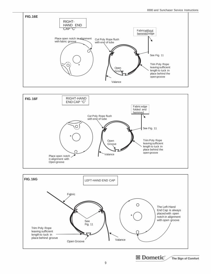
The left-hand end cap is always positioned with the
open notch over the open groove. See FIG. 16G on
page 9.
FIG. 12
CAP A
ROLL UP
WIND TO ADD TORSION
CAP B
CAP C
6
WINDTO ADDTORSION
ROLL UP ROLL DN
Open Groove
Valance
Trim Poly Rope leaving sufficient length to tuck in place behind the open groove
Fabricwithout hemmed edge
TABLE2:TORSIONWINDINGFORFIGURE15 TABLE1:TORSIONWINDINGFORFIGURE14
*Add6additionalturnstotorsionspringwhen
awningisfullyextended.
AWNINGLENGTH ROLLEDUP
TURNS* EXTENDED
TURNS
8' 8 14
9' 8 14
10' 8 14
11' 8 14
12' 8 14
13' 9 15
14' 9 15
15' 10 16
16' 10 16
17' 12 18
18' 12 18
19' 12 18
20' 12 18
21'andabove 12 18
*Add6additionalturnstotorsionspringwhen
awningisfullyextended.
FIG. 15
8300 and Sunchaser Service Instructions
AWNINGLENGTH ROLLED UP
TURNS* EXTENDED
TURNS
8' 5 11
9' 5 11
10' 5 11
11' 5 11
12' 5 11
13' 6 12
14' 6 12
15' 7 13
16' 7 13
17' 9 15
18' 9 15
19' 10 16
20' 10 16
21'andabove 10 16
FIG. 14
1
FIG. 16A
RIGHT-HAND END CAP “A”
Cut Poly Rope flush with end of tube
See Fig. 11
Place open notch in alignment with open groove
7
1
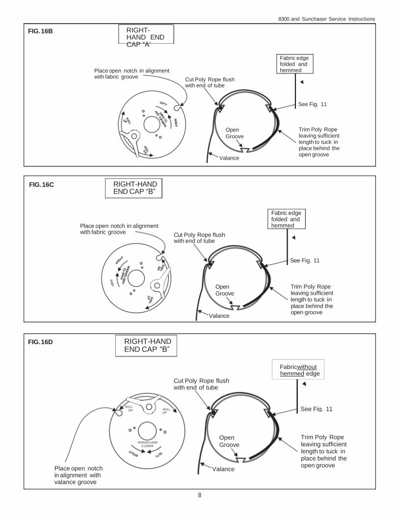
See Fig. 11
Open Groove
Valance
Trim Poly Rope leaving sufficient length to tuck in place behind the open groove
Fabricwithout hemmed edge
RIGHT-HAND END CAP “B”
WINDTO ADDTORSION
ROLL UP
Fabric edge folded and hemmed
Cut Poly Rope flush with end of tube
Trim Poly Rope leaving sufficient length to tuck in place behind the open groove
RIGHT-HAND END CAP “A’
8300 and Sunchaser Service Instructions
FIG. 16B
Place open notch in alignment with fabric groove
See Fig. 11
Open Groove
Valance
FIG. 16C
Place open notch in alignment with fabric groove
See Fig. 11
Open Groove
Valance
FIG. 16D
Cut Poly Rope flush with end of tube
ROLL DN
Place open notch in alignment with valance groove
8
Fabric edge folded and hemmed
Cut Poly Rope flush with end of tube
Trim Poly Rope leaving sufficient length to tuck in place behind the open groove
RIGHT-HAND END CAP “B”
LEFT-HAND END CAP
Valance
The Left-Hand End Cap is always placed with open notch in alignment with open groove
Cut Poly Rope flush with end of tube
Trim Poly Rope leaving sufficient length to tuck in place behind the open groove
8300 and Sunchaser Service Instructions
FIG. 16E
RIGHT-HAND END CAP “C”
Place open notch in alignment with fabric groove
See Fig. 11
Open Groove
Valance
FIG. 16F
Cut Poly Rope flush with end of tube
See Fig. 11
Open Groove
Place open notch in alignment with Open groove
FIG. 16G
Fabric
See Fig. 11
Trim Poly Rope leaving sufficient length to tuck in place behind groove
Open Groove
9
Valance
Trim Poly Rope leaving sufficient length to tuck in place behind the open groove
Fabric edge folded and hemmed
RIGHT-HAND END CAP “C”
Fabricwithout hemmed edge
![Calcul des caractéristiques d’une poutre de sectio[] · 2.3.3 Exemple ... 3.4 Constante de torsion des sections circulaire et rectangulaire.....19 3.5 Le rayon de torsion efficace](https://img.pdfslide.fr/doc/110x75/5b3201687f8b9aae458b92c8/calcul-des-caracteristiques-dune-poutre-de-sectio-233-exemple-34.jpg)

![Calcul des caractéristiques d’une poutre de sectio[] · 3.3 Calcul du rayon de torsion dans une section quelconque.....18 3.4 Constante de torsion des sections circulaire et](https://img.pdfslide.fr/doc/110x75/5b96bf7109d3f206218bcb05/calcul-des-caracteristiques-dune-poutre-de-sectio-33-calcul-du-rayon.jpg)


![ANNALES DE L INSTITUT OURIER · Quillen metric is the product of the L2 metric on A(^) by the analytic torsion of Ray-Singer of ^. The analytic torsion of Ray-Singer [RS] is the regularized](https://img.pdfslide.fr/doc/110x75/60ed6b4ed83f822d92295f50/annales-de-l-institut-ourier-quillen-metric-is-the-product-of-the-l2-metric-on-a.jpg)