Embed Size (px)
Citation preview

Record the following information from the motor and pump nameplates for future reference:
Sur les lignes qui suivent, indiquer les informations suivantes qui se trouvent sur les plaques signalétiques du moteur et de la pompe de façon à pouvoir s’y reporter ultérieurement :
Anote la siguiente información de las chapas del motor y de la bomba para referencia futura:
English ......................................................Pages 2-12Français ..................................................Pages 13-23Español ................................................. Paginas 24-34
Tables • Tableaux • Cuadros ...................Pages 35-47Diagrams • Schémas • Diagramas ...........Pages 48-64
Pump Model No.N° de modèle de la pompeNo. de modelo de la bombaPump Serial No.N° de série de la pompeNo. de serie de la bombaMotor Model No.N° de modèle du moteurNo. de modelo del motorMotor Serial No.N° de série du moteurNo. de serie del motorH.P., Volts/Hz/PhPuissance en CH Volts/Hz/Phase(s)H.P. Voltios/Hz/FaseRated Amp DrawDébit nominal en ampèresCorriente nominal extraída
INSTALLATION AND OPERATING MANUAL
4” Submersible Pumps Two and Three Wire, Single and Three
Phase, 1/2 through 10 H.P., 60 HzNOTICE D’INSTALLATION ET DE
FONCTIONNEMENT
Pompes submersibles de 4 pouces Moteurs bifilaires et trifilaires,
Monophasés et triphasés, Puissance de 1/2 à 10 ch, 60 Hz
MANUAL DE INSTALACIÓN Y FUNCIONAMIENTO
Bombas sumergibles de 4” Bifilares y Trifilares, Monofásicas y
trifásicas, 1/2 hasta 10 H.P., 60 Hz
© 2013 Pentair Ltd. All Rights Reserved. PN280 (REV 02/20/13)
293 WRIGHT STREET, DELAVAN, WI 53115 WWW.PENTAIR.COMPH: 262-728-5551
Safety 2
Important Safety InstructionsSAVE THESE INSTRUCTIONS - This manual contains important instructions that should be followed during installation, operation, and maintenance of the product. Save this manual for future reference.
This is the safety alert symbol. When you see this symbol on your pump or in this manual, look for one of the following signal words and be alert to the potential for personal injury!
indicates a hazard which, if not avoided, will result in death or serious injury.
indicates a hazard which, if not avoided, could result in death or serious injury.
indicates a hazard which, if not avoided, could result in minor or moderate injury.NOTICE addresses practices not related to personal injury.To avoid serious or fatal personal injury and possible property damage, carefully read and follow the safety instructions.
Hazardous voltage. Can shock, burn or cause death. To avoid dangerous or fatal electric shock hazard, use pump only in a water well.
Risk of electrical shock. Do not install this pump in any pond, river, or other open body of water that could be used for swimming or recreation. Do not swim, wade or play in a body of water in which a submersible pump has been installed.• InstallationmustmeetUnitedStatesNational
Electrical Code, Canadian Electrical Code, and local codes (as applicable) for all wiring.
• Disconnectelectricalpowersupplybeforeinstalling or servicing pump.
• Makesurelinevoltageandfrequencyofpower supply match motor nameplate voltage and frequency.
Hazardous pressure.Undercertainconditions, submersible pumps can develop extremelyhighpressure.Installapressurerelief
valve capable of passing entire pump flow at 75PSI(517kPa)whenusinganairoverwaterpressuretank.Installapressurereliefvalvecapableofpassingentirepumpflowat100PSI(690kPa)when using a pre-charged pressure tank.
Risk of freezing. Do not allow pump, pressure tank, piping, or any other system component containing water to freeze. Freezing may damage system, leading to injury or flooding. Allowing pump or system components to freeze will void warranty.California Proposition 65 Warning
This product and related accessories contain chemicals known to the State of California to cause cancer, birth defects or other reproductive harm.
Electrical Grounding Information Hazardous voltage. Can shock, burn, or
kill. To reduce the risk of electrical shock during pump operation, ground and bond the pump and motor as follows:• Toreduceriskofelectricalshockfrommetal
parts of the assembly other than the pump, bond together all metal parts accessible at the well head (including metal discharge pipe, metal well casing, andthelike).Useametalbondingconductorat least as large as the power cable conductors running down the well to the pump’s motor.
• Clamporweld(orbothifnecessary)thisbondingconductor to the grounding means provided with thepump,whichwillbetheequipment-groundingterminal, the grounding conductor on the pump housing,oranequipment-groundinglead.Theequipment-groundinglead,whenprovided,willbe the conductor having green insulation; it may also have one or more yellow stripes.
• Groundthepump,motor,andanymetallicconduit that carries power cable conductors. Groundthesebacktotheservicebyconnectinga copper conductor from the pump, motor, and conduit to the grounding screw provided within the supply-connection box wiring compartment. This conductor must be at least as large as the circuit conductors supplying the pump
Allowing pump or system components to freeze will void warranty.Installpumpaccordingtoallplumbing,pumpandwellcoderequirements.Test well water for purity before using well. Call your local health department for testing procedure.During installation, keep well covered as much as possible to prevent leaves and foreign matter from falling into well. Foreign objects in well can contaminate the water and cause serious mechanical damage to the pump.Pipe joint compound can cause cracking in plastics. UseonlyPTFEpipethreadsealingtapewhensealingjoints in plastic pipe or when connecting pipe to thermoplastic pumps.
Table of ContentsImportantSafetyInstructions . . . . . . . . . . . . . . . 2Pre-Installation . . . . . . . . . . . . . . . . . . . . . . . . . . 3Rotation – (3 Phase only) . . . . . . . . . . . . . . . . . . 3Cabling . . . . . . . . . . . . . . . . . . . . . . . . . . . . . . . . 6Cable Splicing . . . . . . . . . . . . . . . . . . . . . . . . . . 7InitialStart-Up . . . . . . . . . . . . . . . . . . . . . . . . . . 9Effluent Applications . . . . . . . . . . . . . . . . . . . . . . 9C onnecting To Tank / Water System . . . . . . . . . . 9Troubleshooting . . . . . . . . . . . . . . . . . . . . . . . . 10Warranty . . . . . . . . . . . . . . . . . . . . . . . . . . . . . 12Tables . . . . . . . . . . . . . . . . . . . . . . . . . . . . . . . . 35Diagrams . . . . . . . . . . . . . . . . . . . . . . . . . . . . . 48
Pre-Installation 3
Pre-InstallationInspectpumpandmotorfordeliverydamage.Report any damage immediately to the shipping carrier or to your dealer.The well driller should thoroughly develop the well (that is, pump out all fine sand and foreign matter) before pump is installed.Pump performance is based on pumping clear, cold,liquidwater.Warranty is void in the following conditions:• Ifpumphaspumpedexcessivesand–
excessive sand can cause premature wear to pump.
• Ifwateriscorrosive.• Ifentrainedgasorairarepresentinthewater
being pumped – these can reduce flow and cause cavitation which can damage pump.
• Ifpumphasbeenoperatedwithdischargevalve closed – severe internal damage will result.
Installpumpatleast15to20’(4.5to6m)belowthe lowest water level reached with pump running (lowest draw-down water level), and at least 5’ (1.5m)abovethebottomofthewell.See Tables for information on submersible motor overload protection, control box specifications, recommended fusing, and service wiring requirements.AlsoseeDiagrams for typical submersible pump installation wiring.
Wiring/Grounding Hazardous voltage. Can shock, burn,
or cause death. Permanently ground pump, motor and control box before connecting power supply to motor.Groundpumpandmotorinaccordancewithlocalcodesandordinances.Useacoppergroundwireatleast as large as wires carrying current to motor.Motorissuppliedwithacoppergroundwire.Splice this ground wire to a copper conductor that matches motor wire size specified in Cable Sizing Tables. Also see Cable Splicing instructions.Permanently ground pump, motor and control box before connecting power cable to power supply. Connect ground wire to approved ground first and thenconnecttoequipmentbeinginstalled.Donotground to a gas supply line.
Fire and electrical shock hazard.IfusingadropcablelargerthanAWG10(5.5mm²)[forexample,AWG8(8.4mm²)wire]betweenpump and control box, run drop cable to a separate junction box. Connect junction box to controlboxwithAWG10 (5.5mm²)wire.For more information, contact your local code authority.
Wiring ConnectionsInstallationmustmeetUnitedStatesNationalElectrical Code, Canadian Electrical Code and local codes for all wiring (as applicable).Useonlycopperwirewhenmakingconnectionstopump and control box.To avoid over-heating wire and excessive voltage drop at motor, be sure that wire size is at least as large as size listed in cable sizing tables for your horsepower pump and length of wire run.NOTICE See Diagrams for typical wiring hookups and control box identification.NOTICE When built-in overheating protection is not provided, install an approved overload equippedmotorcontrolthatmatchesmotorinput in full load amps. Select or adjust overload element(s) in accordance with control instructions. When built-in overheating protection is provided, use an approved motor control that matches motor input in full load amperes.
Rotation – (3 Phase only)To make sure motor is running in the correct direction, proceed carefully as follows:After electrical connections have been made as outlined, and with pump hanging in well supported from clamp on the discharge pipe, turn on then turn off the switch connecting the motor to the power supply line.Observetherotationofpumpasmotorstarts.Ifconnections are properly made, pump will “jerk” clockwise when looking into the pump discharge whenstarted.Ifthe“jerk”iscounter-clockwise,the motor is running in the wrong direction. Interchangeanytwocableleadswheretheyconnect to the “lead” terminals in the magnetic starter. With connections properly made, and pump loweredintowater,turntheswitchONagainandthe pump should deliver water according to the performance charts.
Overload Protection Of Three Phase Submersible Motors – Class 10 Protection Required
The characteristics of submersible motors are different from standard motors and special overloadprotectionisrequired.Ifthemotorisstalled,theoverloadmusttripwithin10secondstoprotectthemotorwindings.All recommended overload selections are of the ambient compensated type to maintain protection at high and low air temperatures.All heaters and amp settings shown are based on total line amps. When a six-lead motor is used with a Wye-Delta starter, divide motor amps by 1.732tomakeyourselectionoradjustmentforheaters carrying phase amps.
Pre-Installation 4
See Table IforoverloadspecificationsforPENTEKmotors.NOTICE Warranty on three phase submersible motorsisvoidunlessproperquicktripprotectionin all three motor lines is used.
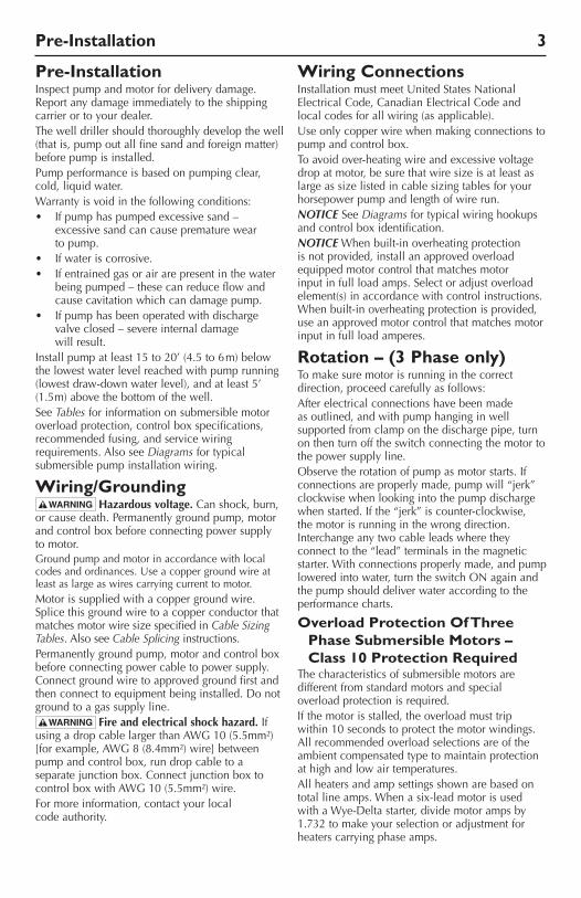
Surge Arresters in Control BoxGrounding: When the box has a surge arrester, the surgearresterMUSTbegrounded,metaltometal,all the way to the water strata for the arrester to be effective.Groundingthearrestertoadrivengroundrod provides little or no protection for the motor.NOTICESurgearrestersDONOTprotectagainstdirect lightning strikes.Installgroundedsurgearresterstoprotectpumpfromhighvoltagesurges.Installarresterontheincoming power line to control box or pressure switch, as close to pump motor as possible. See Figures1and2forinstallationwiringdiagramsfor arresters.
NOTICEGroundthearresterwithaAWG10orlargerbarewire.Groundaccordingtolocalcode requirements.NOTICEIfsurgearresterswiredintothecontrol box do not comply with local electrical code, contact power company for correct wiring information.
Recommended Adjustable Overload Relays
AEGSeries: B17S,B27S,B27-2.Allen Bradley: Bulletin193,SMP-Class10only.Fanal Types: K7orK7DthroughK400.Franklin Electric: Subtrol-Plus.GeneralElectric: CR4G,CR7G,RT*1,RT*2,RTF3,RT*4,
CR324X-Class10only.Klockner-MoellerTypes: Z00,Z1,Z4,PKZM1,PKZM3,PKZ2.Lovato: RC9,RC22,RC80,RF9,RF25,RF95.Siemens Types: 3UA50,-52,-54,-55,-58,-59,-60,-61,-62,
-66,-68,-70,3VUI3,3VE,3UB(Class5).Sprecher and Schuh Types: CT,CT1,CTA1,CT3K,CT3-12thruCT3-42,
KTA3,CEF1&CET3setat6sec.max.,CEP7Class10,CT4,6,&7,CT3.
SquareD/Telemecanique: Class9065typesTD,TE,TF,TG,TJ,TK,TR,
TJE,TJF(Class10)orLR1-D,LR1-F,LR2-D13,-D23,-D33,Types18A,32A,SS-Class10,SR-Class10and63-A-LBSeries.Integral18,32,63,GV2-L,GV2-M,GV2-P,GV3-M(1.6-10amponly).
Westinghouse Types: FT13,FT23,FT33,FT43,K7D,K27D,K67D,
Advantage(Class10),MOR,IQ500(Class5).Other relay types from these manufacturers or from other manufacturers may or may not provide acceptable protection. Contact Pentair Customer Service for more information.Some approved overload types may not be available for all of the listed motor ratings. When relays are used with current transformers, divide the specified amps by the transformer ratio to obtain the relay setting.
Surge�Arrester
Line
L1 L2 L3
T1 T2 T3
3 Phase Surge Arrester�(650 Volt Maximum)
Figure 2 - Three Phase Surge Arrester (650 Volt Maximum) Wiring Diagram
Control�Box
L1 L2 R Y B
Surge�Arrester
Typical Surge Arrester�230V Single Phase
Figure 1 – Typical 3 Wire, Single Phase, 230 Volt Surge Arrester Wiring Diagram
Pre-Installation 5
Calculating Cable SizeWhen two different sizes can
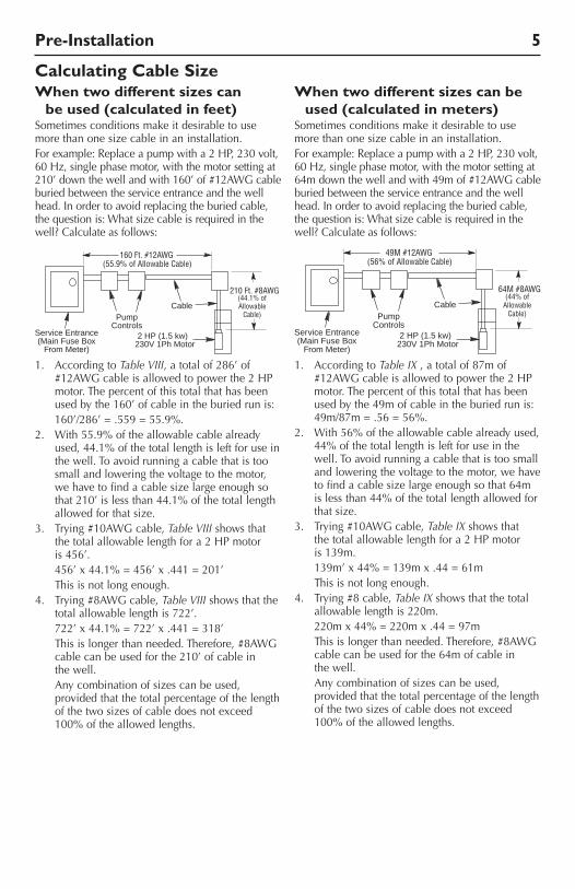
be used (calculated in feet)Sometimes conditions make it desirable to use more than one size cable in an installation.Forexample:Replaceapumpwitha2HP,230volt,60Hz,singlephasemotor,withthemotorsettingat210’downthewellandwith160’of#12AWGcableburied between the service entrance and the well head.Inordertoavoidreplacingtheburiedcable,thequestionis:Whatsizecableisrequiredinthewell? Calculate as follows:
1. AccordingtoTable VIII,atotalof286’of#12AWGcableisallowedtopowerthe2HPmotor. The percent of this total that has been usedbythe160’ofcableintheburiedrunis:
160’/286’=.559=55.9%.2. With55.9%oftheallowablecablealready
used,44.1%ofthetotallengthisleftforuseinthe well. To avoid running a cable that is too small and lowering the voltage to the motor, we have to find a cable size large enough so that210’islessthan44.1%ofthetotallengthallowed for that size.
3. Trying#10AWGcable, Table VIII shows that the total allowable length for a 2 HP motor is 456’.
456’x44.1%=456’x.441=201’ This is not long enough.4. Trying#8AWGcable,Table VIII shows that the
total allowable length is 722’. 722’x44.1%=722’x.441=318’ Thisislongerthanneeded.Therefore,#8AWG
cablecanbeusedforthe210’ofcableinthe well.
Any combination of sizes can be used, provided that the total percentage of the length of the two sizes of cable does not exceed 100%oftheallowedlengths.
When two different sizes can be used (calculated in meters)
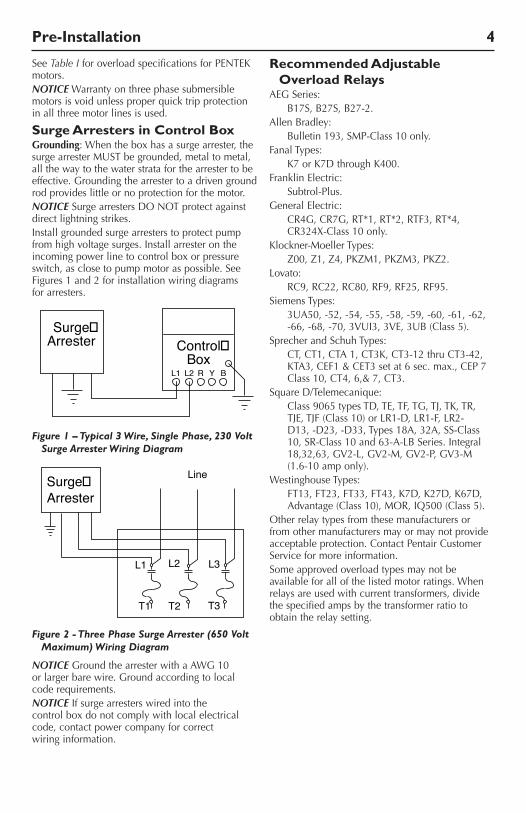
Sometimes conditions make it desirable to use more than one size cable in an installation.Forexample:Replaceapumpwitha2HP,230volt,60Hz,singlephasemotor,withthemotorsettingat64mdownthewellandwith49mof#12AWGcableburied between the service entrance and the well head.Inordertoavoidreplacingtheburiedcable,thequestionis:Whatsizecableisrequiredinthewell? Calculate as follows:
1. AccordingtoTable IX , a total of 87m of #12AWGcableisallowedtopowerthe2HPmotor. The percent of this total that has been usedbythe49mofcableintheburiedrunis:49m/87m=.56=56%.
2. With56%oftheallowablecablealreadyused,44%ofthetotallengthisleftforuseinthewell. To avoid running a cable that is too small and lowering the voltage to the motor, we have tofindacablesizelargeenoughsothat64mislessthan44%ofthetotallengthallowedforthat size.
3. Trying#10AWGcable,Table IX shows that the total allowable length for a 2 HP motor is 139m.
139m’x44%=139mx.44=61m This is not long enough.4. Trying#8cable,Table IX shows that the total
allowablelengthis220m. 220mx44%=220mx.44=97m Thisislongerthanneeded.Therefore,#8AWG
cablecanbeusedforthe64mofcableinthe well.
Any combination of sizes can be used, provided that the total percentage of the length of the two sizes of cable does not exceed 100%oftheallowedlengths.
CablePump
ControlsService Entrance(Main Fuse Box
From Meter)
2 HP (1.5 kw) 230V 1Ph Motor
49M #12AWG
64M #8AWG
(56% of Allowable Cable)
(44% ofAllowable
Cable)
5731 1207
CablePump
ControlsService Entrance(Main Fuse Box
From Meter)
2 HP (1.5 kw) 230V 1Ph Motor
160 Ft. #12AWG
210 Ft. #8AWG
(55.9% of Allowable Cable)
(44.1% ofAllowable
Cable)
5731 1207
Cabling
Cabling 6
Installation Wiring Diagrams - Single Phase, 3 Wire
Hazardous voltage. Can shock, burn, orkill.Groundcontrolbox,allmetalplumbing,and motor frame with copper wire in compliance withlocalcodes.Useagroundwireatleastaslarge in gauge as the wires supplying power to the motor.NOTICEFormotorsof1-1/2HPandabove,usea magnetic starter to avoid damage to pressure switch. Consult factory for wiring information.Permanently close all unused openings in this and otherequipmentenclosures.Disconnect power to control box before working on or around control box, pipes, cable, pump, or motor.To be sure that starting relay will function and that overload will not “nuisance trip”, install control box vertically with top side up.Wire control box as shown in Diagrams. Submersible pump will not operate without a controlbox,andsomeboxesrequireaswitchora jumper lead between ‘SW’ and ‘L2’ terminals. Operation without control box will burn out the pump motor.InstallationmustmeetUnitedStatesNationalElectrical Code, Canadian Electrical Code, and local codes for all wiring (as applicable).If main overload trips, look for:1. Shortedcapacitor2. Voltageproblems3. Overloaded or locked pump.NOTICE Matchmotortocontrolboxormotorcontrol as shown in Specifications.
Liquid Level (Pump Down) Controls:
Usepumpdowncontrolsonwellswithlowflowto prevent pumping well dry. See Installation Diagramsforproperinstallation.Groundcontrolsaccordingtolocalcoderequirements.Ifstartoverloadtrips,replacestartrelay.Resetandanalyze for tripping cause. To avoid motor burnout, do not remove or short circuit overload protection.
C hecking Procedure (All Control Boxes):
Hazardous voltage. Can shock, burn, or cause death. Disconnect power to control box before doing these check procedures.
A. General Procedures. (Power to control box disconnected)1. Disconnectline.2. Inspectfordamagedorburnedparts,loose
connections, etc.3. Check for misconnections against diagram
in control box.4. Ifboxistoohot,circuitbreakersmaytrip
orfusesblow.Ventilateorshadebox.Moveawayfromheatsource.
5. Ifproblemhasnotbeenfound,checkmotorandcontrolbox.Usetestprocedures that follow.
B. Ground (Insulation Resistance) Test. (Power to control box disconnected)1. OhmmeterSetting:Highestscale(usually
Rx100KorRx10,000).2. Terminal Connections: One ohmmeter lead
to“Ground”screwoncontrolboxandtouch other lead to each of the terminals on terminal board.
3. Ohmmeter Reading: Pointer should remain at infinity (∞) and not deflect.
C. Capacitor Tests. (Power to control box disconnected)
Risk of electric shock. Short capacitor across terminals before testing.1. OhmmeterSetting:Rx1000.2. Terminal Connections: Connect ohmmeter
leads to black and orange wires out of capacitor case.
3. Ohmmeter Reading: Pointer should swing toward “zero” and “float” back to (∞). Capacitor is shorted if pointer does not move back to (∞), open if it does not move from (∞).
4. To reset capacitor, reverse ohmmeter connection to capacitor terminals.
D. Triac Test. (Solid state switch only)1. OhmmeterSetting:Rx1000.2. Connect the leads to “R” (start) terminal
and to orange lead terminal on start switch.
3. Ohmmeterreading:Infinity(∞).E. Coil Test. (Solid state switch only)
1. OhmmeterSetting:Rx1.2. Connect leads to “Y” (common) and L2
terminal and to orange lead terminal on start switch.
3. Ohmmeterreading:Infinity(∞).
Cable Splicing 7
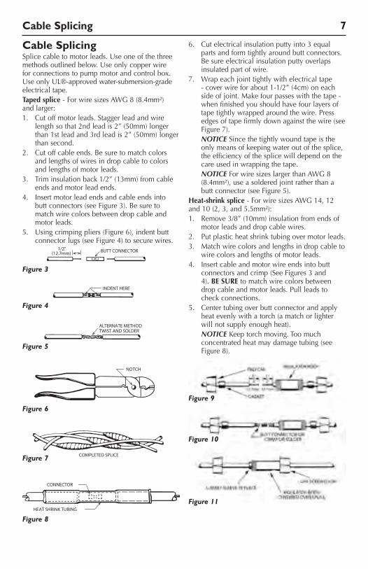
Cable SplicingSplicecabletomotorleads.Useoneofthethreemethodsoutlinedbelow.Useonlycopperwirefor connections to pump motor and control box. UseonlyUL®-approvedwater-submersion-gradeelectrical tape.Taped splice-ForwiresizesAWG8(8.4mm²)and larger:1. Cutoffmotorleads.Staggerleadandwire
lengthsothat2ndleadis2”(50mm)longerthan1stleadand3rdleadis2”(50mm)longerthan second.
2. Cut off cable ends. Be sure to match colors and lengths of wires in drop cable to colors and lengths of motor leads.
3. Triminsulationback1/2”(13mm)fromcableends and motor lead ends.
4. Insertmotorleadendsandcableendsintobutt connectors (see Figure 3). Be sure to match wire colors between drop cable and motor leads.
5. Usingcrimpingpliers(Figure6),indentbuttconnector lugs (see Figure 4) to secure wires.
6. Cutelectricalinsulationputtyinto3equalparts and form tightly around butt connectors. Be sure electrical insulation putty overlaps insulated part of wire.
7. Wrap each joint tightly with electrical tape -coverwireforabout1-1/2”(4cm)oneachsideofjoint.Makefourpasseswiththetape-when finished you should have four layers of tape tightly wrapped around the wire. Press edges of tape firmly down against the wire (see Figure 7).
NOTICE Since the tightly wound tape is the only means of keeping water out of the splice, the efficiency of the splice will depend on the care used in wrapping the tape.
NOTICEForwiresizeslargerthanAWG8(8.4mm²),useasolderedjointratherthanabutt connector (see Figure 5).
Heat-shrink splice -ForwiresizesAWG14,12and10(2,3,and5.5mm²):1. Remove3/8”(10mm)insulationfromendsof
motor leads and drop cable wires.2. Put plastic heat shrink tubing over motor leads.3. Matchwirecolorsandlengthsindropcableto
wire colors and lengths of motor leads.4. Insertcableandmotorwireendsintobutt
connectors and crimp (See Figures 3 and 4). BE SURE to match wire colors between drop cable and motor leads. Pull leads to check connections.
5. Center tubing over butt connector and apply heat evenly with a torch (a match or lighter will not supply enough heat).
NOTICEKeeptorchmoving.Toomuchconcentrated heat may damage tubing (see Figure 8).
Figure 9
Figure 10
Figure 11
Figure 3
Figure 4
Figure 5
Figure 6
Figure 7
Figure 8
Installation 8
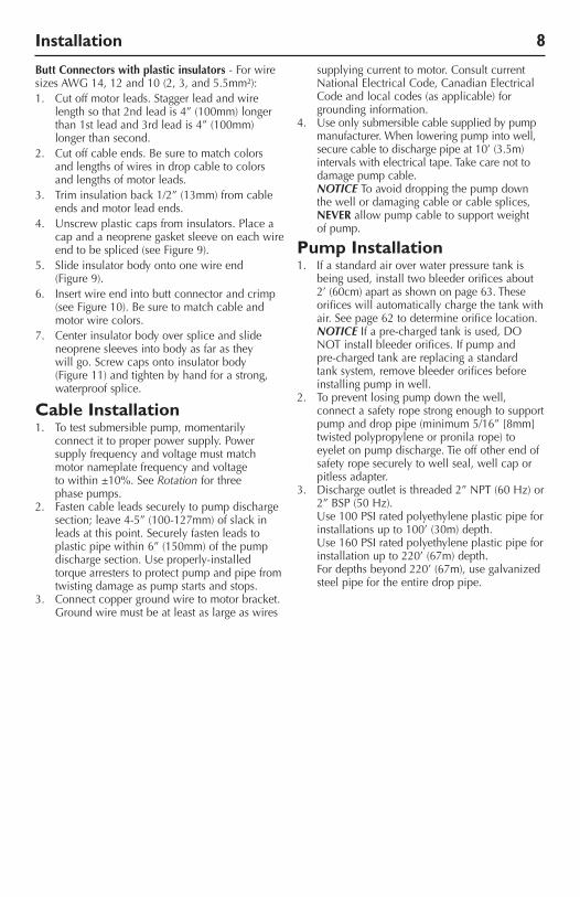
Butt Connectors with plastic insulators - For wire sizesAWG14,12and10(2,3,and5.5mm²):1. Cutoffmotorleads.Staggerleadandwire
lengthsothat2ndleadis4”(100mm)longerthan1stleadand3rdleadis4”(100mm)longer than second.
2. Cut off cable ends. Be sure to match colors and lengths of wires in drop cable to colors and lengths of motor leads.
3. Triminsulationback1/2”(13mm)fromcableends and motor lead ends.
4. Unscrewplasticcapsfrominsulators.Placeacap and a neoprene gasket sleeve on each wire endtobespliced(seeFigure9).
5. Slide insulator body onto one wire end (Figure 9).
6. Insertwireendintobuttconnectorandcrimp(seeFigure10).Besuretomatchcableandmotor wire colors.
7. Center insulator body over splice and slide neoprene sleeves into body as far as they will go. Screw caps onto insulator body (Figure11)andtightenbyhandforastrong,waterproof splice.
Cable Installation1. Totestsubmersiblepump,momentarily
connect it to proper power supply. Power supplyfrequencyandvoltagemustmatchmotornameplatefrequencyandvoltagetowithin±10%.SeeRotation for three phase pumps.
2. Fasten cable leads securely to pump discharge section;leave4-5”(100-127mm)ofslackinleads at this point. Securely fasten leads to plasticpipewithin6”(150mm)ofthepumpdischargesection.Useproperly-installedtorquearresterstoprotectpumpandpipefromtwisting damage as pump starts and stops.
3. Connect copper ground wire to motor bracket. Groundwiremustbeatleastaslargeaswires
supplying current to motor. Consult current NationalElectricalCode,CanadianElectricalCode and local codes (as applicable) for grounding information.
4. Useonlysubmersiblecablesuppliedbypumpmanufacturer. When lowering pump into well, securecabletodischargepipeat10’(3.5m)intervals with electrical tape. Take care not to damage pump cable.
NOTICE To avoid dropping the pump down the well or damaging cable or cable splices, NEVER allow pump cable to support weight of pump.
Pump Installation1. Ifastandardairoverwaterpressuretankis
being used, install two bleeder orifices about 2’(60cm)apartasshownonpage63.Theseorifices will automatically charge the tank with air.Seepage62todetermineorificelocation.
NOTICE Ifapre-chargedtankisused,DONOTinstallbleederorifices.Ifpumpandpre-charged tank are replacing a standard tank system, remove bleeder orifices before installing pump in well.
2. To prevent losing pump down the well, connect a safety rope strong enough to support pumpanddroppipe(minimum5/16”[8mm]twisted polypropylene or pronila rope) to eyelet on pump discharge. Tie off other end of safety rope securely to well seal, well cap or pitless adapter.
3. Dischargeoutletisthreaded2”NPT(60Hz)or2”BSP(50Hz).
Use100PSIratedpolyethyleneplasticpipeforinstallationsupto100’(30m)depth.
Use160PSIratedpolyethyleneplasticpipeforinstallationupto220’(67m)depth.
Fordepthsbeyond220’(67m),usegalvanizedsteel pipe for the entire drop pipe.
Installation 9
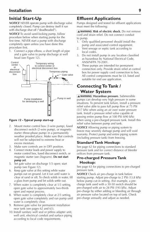
Initial Start-UpNOTICE NEVERoperatepumpwithdischargevalvecompletely closed. Pump can destroy itself if run with discharge shut off (“deadheaded”).NOTICE To avoid sand-locking pump, follow procedure below when starting pump for the firsttime.NEVERstartapumpwithdischargecompletely open unless you have done this procedure first.1. Connectapipeelbow,ashortlengthofpipe
and a gate valve to pump discharge at well head(seeFigure12).
2. Mountmotorcontrolbox(3-wirepump),fuseddisconnect switch (2-wire pump), or magnetic starter (three-phase pump) in a permanently weatherproofedplace.Makesurethatcontrolswill not be subjected to extreme heat or excess moisture.
3. MakesurecontrolsareinOFFposition.4. Connect motor leads and power supply to
motor control box, fused disconnect switch, or magnetic starter (see Diagrams). Do not start pump yet.
5. Setgatevalveondischarge1/3open;startpump(seeFigure12).
6. Keepgatevalveatthissettingwhilewaterpumps out on ground. Let it run until water is clear of sand or silt. To check solids in water, fill a glass from pump and let solids settle out.
7. Whenwateriscompletelyclearat1/3setting,open gate valve to approximately two-thirds open and repeat process.
8. When water is completely clear at 2/3 setting, open gate valve completely and run pump until water is completely clear.
9. Removegatevalveforpermanentinstallationneartank(seepages62and63).
10.Installsanitarywellsealorpitlessadapterunit,well unit, electrical conduit and surface piping accordingtolocalcoderequirements.
Effluent ApplicationsPumps designed and tested for effluent applications must meet the following:
Risk of electric shock. Do not remove cord and strain relief. Do not connect conduit to pump.1. Onlyqualifiedpersonnelshouldinstallthe
pumpandassociatedcontrolequipment.2. Ventsewageorseptictankaccordingto
local codes.3. Do not install pump in any location classified
ashazardousbyNationalElectricalCode,ANSI/NFPA70-2001.
4. These pumps are intended for permanent connection only. Provide strain relief at control box for power supply cord connection to box. AllcontrolcomponentsmustbeULlistedandsuitable for end use application.
C onnecting To Tank / Water System
Hazardous pressure. Submersible pumps can develop very high pressure in some situations. To prevent tank failure, install a pressure reliefvalveabletopassfullpumpflowat75 PSI(517 kPa)whenusinganairoverwaterpressuretank.Installapressurereliefvalvecapableofpassingentirepumpflowat100 PSI(690 kPa)whenusingapre-chargedpressuretank.Installthisrelief valve between pump and tank.NOTICE Allowing pump or piping system to freeze may severely damage pump and will void warranty. Protect pump and entire piping system (including pressure tank) from freezing.
Standard Tank Hookup:Seepage62forpipingconnectionstostandardpressure tank and for correct distance of bleeder orifices from pressure tank.
Pre-charged Pressure Tank Hookup:
Seepage63forpipingconnectionstopre-chargedpressure tank.NOTICE Check air pre-charge in tank before startingpump.Adjustpre-chargeto2 PSI(13.8 kPa)below pump cut-in setting. (For example, a pre-chargetankusedwitha30-50switchshouldbepre-chargedwithairto28PSI(193kPa).Adjustpre-charge by either adding or bleeding air through air pressure valve located on top of tank. Check pre-charge annually and adjust as needed.
Controlcenter
orelectrical
disconnectbox
Temporary wiringto control center or
electrical disconnect boxTemporary piping
Gate valve
Pump in wellPump installationfor developing a well
689 0993
Figure 12 - Typical pump start-up
Troubleshooting
Troubleshooting 10
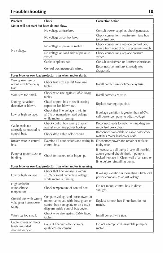
Problem Check Corrective ActionMotor will not start but fuses do not blow.
Novoltage.
Novoltageatfusebox. Consult power supplier, check generator.
Novoltageatcontrolbox.Check connections, rewire from fuse box to control box.
Novoltageatpressureswitch.Check connections, replace control box, rewire from control box to pressure switch.
Novoltageonloadsideofpressureswitch.
Check connections, replace pressure switch.
Cable or splices bad. Consult serviceman or licensed electrician.
Control box incorrectly wired.Reconnect control box correctly (see Diagrams).
Fuses blow or overload protector trips when motor starts.Wrong size fuse or wrong size time delay fuse.
Check fuse size against Fuse Size tables.
Installcorrectfuseortimedelayfuse.
Wire size too small.Check wire size against Cable Sizing tables.
Installcorrectsizewire.
Starting capacitor defective or blown.
Check control box to see if starting capacitor has blown out.
Replace starting capacitor.
Low or high voltage.Check that line voltage is within ±10%ofnameplateratedvoltagewhile motor is running.
Ifvoltagevariationisgreaterthan±10%,call power company to adjust voltage.
Cable leads not correctly connected to control box.
Check control box wiring diagram against incoming power hookup.
Reconnect leads to match wiring diagram in control box cover.
Check drop cable color coding.Reconnect drop cable so cable color code matches motor lead color code.
Broken wire in control box.
Examine all connections and wiring in control box.
Disconnect power and repair or replace faulty wire.
Pump or motor stuck or binding.
Check for locked rotor in pump.
Ifnecessary,pullpump(makeallpossibleabovegroundchecksfirst).Ifpumpislocked, replace it. Clean well of all sand or lime before reinstalling pump.
Fuses blow or overload protector trips when motor is running.
Low or high voltage.Check that line voltage is within ±10%ofratednameplatevoltagewhile motor is running.
Ifvoltagevariationismorethan±10%,callpower company to adjust voltage.
High ambient (atmospheric temperature).
Check temperature of control box.Do not mount control box in direct sunlight.
Control box with wrong voltage or horsepower rating.
Compare voltage and horsepower on motor nameplate with those given on control box nameplate or on circuit diagram inside control box cover.
Replace control box if numbers do not match.
Wire size too small.Check wire size against Cable Sizing tables.
Installcorrectwiresize.
Cable splices or motor leads grounded, shorted, or open.
Consult licensed electrician or qualifiedserviceman.
Do not attempt to disassemble pump or motor.
Troubleshooting 11
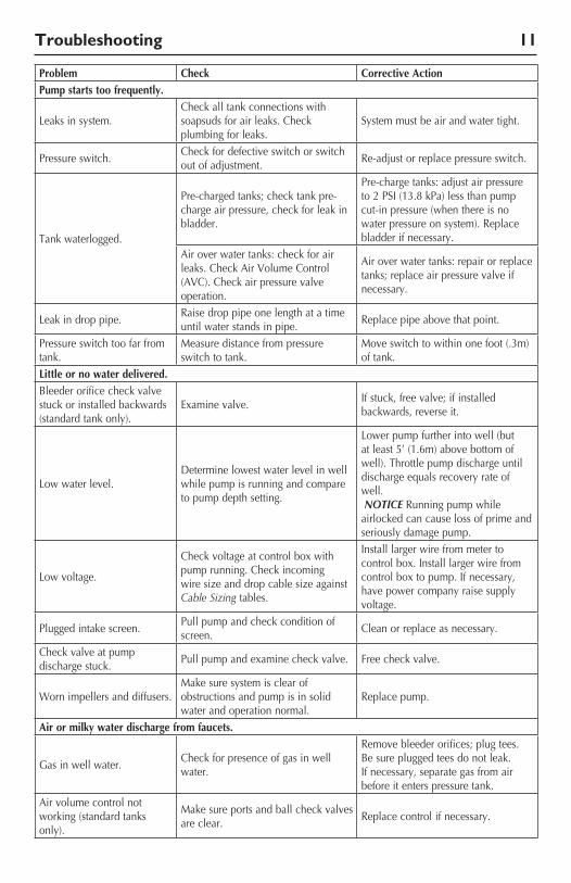
Problem Check Corrective ActionPump starts too frequently.
Leaks in system.Check all tank connections with soapsuds for air leaks. Check plumbing for leaks.
System must be air and water tight.
Pressure switch.Check for defective switch or switch out of adjustment.
Re-adjust or replace pressure switch.
Tank waterlogged.
Pre-charged tanks; check tank pre-charge air pressure, check for leak in bladder.
Pre-charge tanks: adjust air pressure to2PSI(13.8kPa)lessthanpumpcut-in pressure (when there is no water pressure on system). Replace bladder if necessary.
Air over water tanks: check for air leaks.CheckAirVolumeControl(AVC).Checkairpressurevalveoperation.
Air over water tanks: repair or replace tanks; replace air pressure valve if necessary.
Leak in drop pipe.Raise drop pipe one length at a time until water stands in pipe.
Replace pipe above that point.
Pressure switch too far from tank.
Measuredistancefrompressureswitch to tank.
Moveswitchtowithinonefoot(.3m)of tank.
Little or no water delivered.Bleeder orifice check valve stuck or installed backwards (standard tank only).
Examine valve.Ifstuck,freevalve;ifinstalledbackwards, reverse it.
Low water level.Determine lowest water level in well while pump is running and compare to pump depth setting.
Lower pump further into well (but atleast5’(1.6m)abovebottomofwell). Throttle pump discharge until dischargeequalsrecoveryrateofwell. NOTICE Running pump while airlocked can cause loss of prime and seriously damage pump.
Low voltage.
Check voltage at control box with pump running. Check incoming wire size and drop cable size against Cable Sizing tables.
Installlargerwirefrommetertocontrolbox.Installlargerwirefromcontrolboxtopump.Ifnecessary,have power company raise supply voltage.
Plugged intake screen.Pull pump and check condition of screen.
Clean or replace as necessary.
Check valve at pump discharge stuck.
Pull pump and examine check valve. Free check valve.
Worn impellers and diffusers.Makesuresystemisclearofobstructions and pump is in solid water and operation normal.
Replace pump.
Air or milky water discharge from faucets.
Gasinwellwater.Check for presence of gas in well water.
Remove bleeder orifices; plug tees. Be sure plugged tees do not leak. Ifnecessary,separategasfromairbefore it enters pressure tank.
Air volume control not working (standard tanks only).
Makesureportsandballcheckvalvesare clear.
Replace control if necessary.

Warranty 12
WarrantyLimited WarrantyPENTAIRwarrantstotheoriginalconsumerpurchaser(“Purchaser”or“You”)oftheproductslistedbelow,thattheywillbefreefrom defects in material and workmanship for the Warranty Period shown below.
Product Warranty Period
Water Systems Products — jet pumps, small centrifugal pumps, submersible pumps and related accessories
whichever occurs first: 12monthsfromdateoforiginalinstallation, 18monthsfromdateofmanufacture
PENTEKINTELLIDRIVE™12monthsfromdateoforiginalinstallation,or 18monthsfromdateofmanufacture
Pro-Source® Composite Tanks 5 years from date of original installationPro-Source® Steel Pressure Tanks 5 years from date of original installationPro-Source® Epoxy-Line Tanks 3 years from date of original installation
Sump/Sewage/Effluent Products12monthsfromdateoforiginalinstallation,or 18monthsfromdateofmanufacture
Our warranty will not apply to any product that, in our sole judgment, has been subject to negligence, misapplication, improper installation, or improper maintenance. Without limiting the foregoing, operating a three phase motor with single phasepowerthroughaphaseconverterwillvoidthewarranty.Notealsothatthreephasemotorsmustbeprotectedbythree-leg,ambientcompensated,extra-quicktripoverloadrelaysoftherecommendedsizeorthewarrantyisvoid.Youronlyremedy,andPENTAIR’sonlyduty,isthatPENTAIRrepairorreplacedefectiveproducts(atPENTAIR’schoice).Youmustpayalllaborandshippingchargesassociatedwiththiswarrantyandmustrequestwarrantyservicethroughtheinstallingdealerassoonasaproblemisdiscovered.NorequestforservicewillbeacceptedifreceivedaftertheWarrantyPeriodhasexpired.Thiswarranty is not transferable.PENTAIRISNOTLIABLEFORANYCONSEQUENTIAL,INCIDENTAL,ORCONTINGENTDAMAGESWHATSOEVER.THEFOREGOINGLIMITEDWARRANTIESAREEXCLUSIVEANDINLIEUOFALLOTHEREXPRESSANDIMPLIEDWARRANTIES,INCLUDINGBUTNOTLIMITEDTOIMPLIEDWARRANTIESOFMERCHANTABILITYANDFITNESSFORAPARTICULARPURPOSE.THEFOREGOINGLIMITEDWARRANTIESSHALLNOTEXTENDBEYONDTHEDURATIONPROVIDEDHEREIN.Somestatesdonotallowtheexclusionorlimitationofincidentalorconsequentialdamagesorlimitationsonhowlonganimpliedwarranty lasts, so the above limitations or exclusions may not apply to You. This warranty gives You specific legal rights and You may also have other rights which vary from state to state.ThisLimitedWarrantyiseffectiveJune1,2011andreplacesallundatedwarrantiesandwarrantiesdatedbeforeJune1,2011.
PENTAIR 293 Wright St., Delavan, WI 53115
Phone (262) 728-5551 • Fax (262) 728-7323
Tables • Tableaux • Cuadros 35
S ubmersible Motor Control, Fusing, and Wiring Specifications • Boîte à commande du moteur submersible et des caractéristiques des fusibles et des fils • Control de motor sumergible y Especificaciones sobre los fusibles y cables
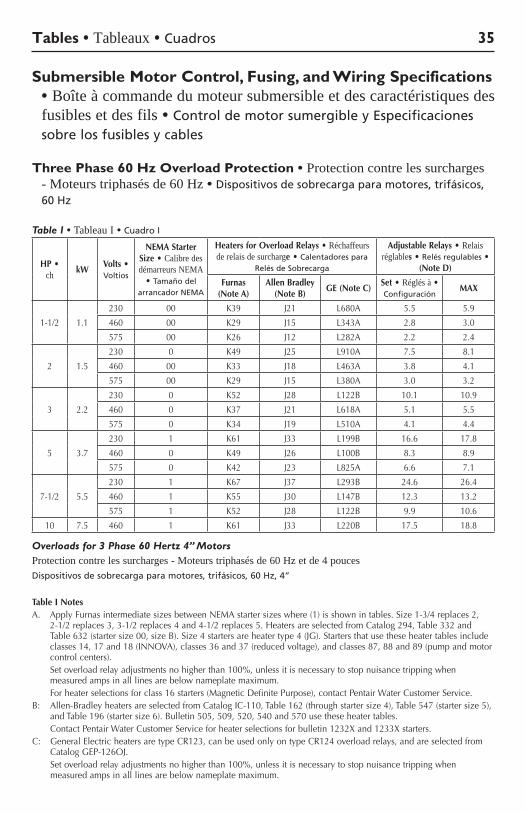
Three Phase 60 Hz Overload Protection • Protection contre les surcharges - Moteurs triphasés de 60 Hz • Dispositivos de sobrecarga para motores, trifásicos, 60 Hz
Table I • Tableau I • Cuadro I
HP • ch kW
Volts • Voltios
NEMA Starter Size • Calibre des démarreurs NEMA
• Tamaño del arrancador NEMA
Heaters for Overload Relays • Réchaffeurs de relais de surcharge • Calentadores para
Relés de Sobrecarga
Adjustable Relays • Relais réglables • Relés regulables •
(Note D)
Furnas (Note A)
Allen Bradley (Note B)
GE (Note C)Set • Réglés à • Configuración
MAX
1-1/2 1.1
230 00 K39 J21 L680A 5.5 5.9
460 00 K29 J15 L343A 2.8 3.0
575 00 K26 J12 L282A 2.2 2.4
2 1.5
230 0 K49 J25 L910A 7.5 8.1
460 00 K33 J18 L463A 3.8 4.1
575 00 K29 J15 L380A 3.0 3.2
3 2.2
230 0 K52 J28 L122B 10.1 10.9
460 0 K37 J21 L618A 5.1 5.5
575 0 K34 J19 L510A 4.1 4.4
5 3.7
230 1 K61 J33 L199B 16.6 17.8
460 0 K49 J26 L100B 8.3 8.9
575 0 K42 J23 L825A 6.6 7.1
7-1/2 5.5
230 1 K67 J37 L293B 24.6 26.4
460 1 K55 J30 L147B 12.3 13.2
575 1 K52 J28 L122B 9.9 10.6
10 7.5 460 1 K61 J33 L220B 17.5 18.8
Overloads for 3 Phase 60 Hertz 4” MotorsProtection contre les surcharges - Moteurs triphasés de 60 Hz et de 4 poucesDispositivos de sobrecarga para motores, trifásicos, 60 Hz, 4”
Table I NotesA. ApplyFurnasintermediatesizesbetweenNEMAstartersizeswhere(1)isshownintables.Size1-3/4replaces2,
2-1/2replaces3,3-1/2replaces4and4-1/2replaces5.HeatersareselectedfromCatalog294,Table332andTable632(startersize00,sizeB).Size4startersareheatertype4(JG).Startersthatusetheseheatertablesincludeclasses14,17and18(INNOVA),classes36and37(reducedvoltage),andclasses87,88and89(pumpandmotorcontrol centers).
Setoverloadrelayadjustmentsnohigherthan100%,unlessitisnecessarytostopnuisancetrippingwhenmeasured amps in all lines are below nameplate maximum.
Forheaterselectionsforclass16starters(MagneticDefinitePurpose),contactPentairWaterCustomerService.B: Allen-BradleyheatersareselectedfromCatalogIC-110,Table162(throughstartersize4),Table547(startersize5),
andTable196(startersize6).Bulletin505,509,520,540and570usetheseheatertables. ContactPentairWaterCustomerServiceforheaterselectionsforbulletin1232Xand1233Xstarters.C: GeneralElectricheatersaretypeCR123,canbeusedonlyontypeCR124overloadrelays,andareselectedfrom
CatalogGEP-126OJ. Setoverloadrelayadjustmentsnohigherthan100%,unlessitisnecessarytostopnuisancetrippingwhen
measured amps in all lines are below nameplate maximum.
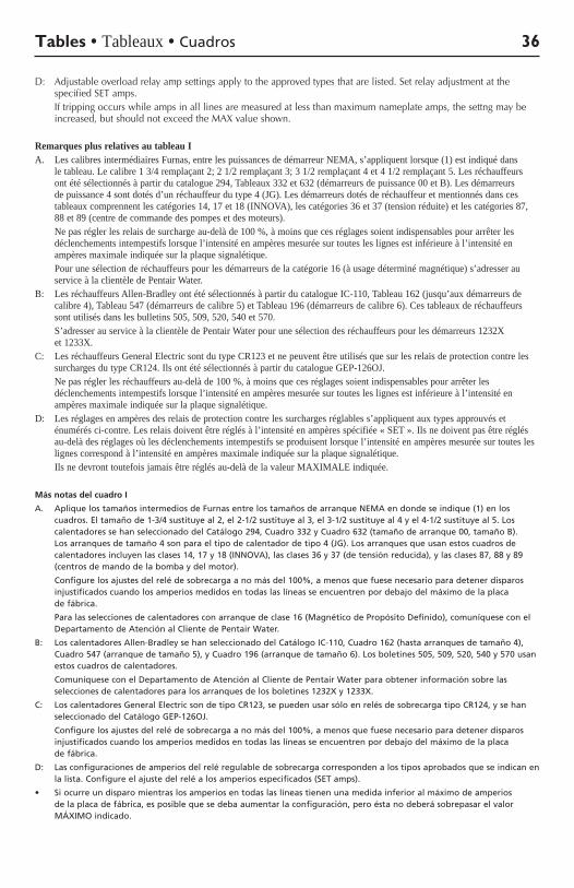
D: Adjustable overload relay amp settings apply to the approved types that are listed. Set relay adjustment at the specified SET amps.
Iftrippingoccurswhileampsinalllinesaremeasuredatlessthanmaximumnameplateamps,thesettngmaybeincreased,butshouldnotexceedtheMAXvalueshown.
Remarques plus relatives au tableau IA. Les calibres intermédiaires Furnas, entre les puissances de démarreur NEMA, s’appliquent lorsque (1) est indiqué dans
le tableau. Le calibre 1 3/4 remplaçant 2; 2 1/2 remplaçant 3; 3 1/2 remplaçant 4 et 4 1/2 remplaçant 5. Les réchauffeurs ont été sélectionnés à partir du catalogue 294, Tableaux 332 et 632 (démarreurs de puissance 00 et B). Les démarreurs de puissance 4 sont dotés d’un réchauffeur du type 4 (JG). Les démarreurs dotés de réchauffeur et mentionnés dans ces tableaux comprennent les catégories 14, 17 et 18 (INNOVA), les catégories 36 et 37 (tension réduite) et les catégories 87, 88 et 89 (centre de commande des pompes et des moteurs).
Ne pas régler les relais de surcharge au-delà de 100 %, à moins que ces réglages soient indispensables pour arrêter les déclenchements intempestifs lorsque l’intensité en ampères mesurée sur toutes les lignes est inférieure à l’intensité en ampères maximale indiquée sur la plaque signalétique.
Pour une sélection de réchauffeurs pour les démarreurs de la catégorie 16 (à usage déterminé magnétique) s’adresser au service à la clientèle de Pentair Water.
B: Les réchauffeurs Allen-Bradley ont été sélectionnés à partir du catalogue IC-110, Tableau 162 (jusqu’aux démarreurs de calibre 4), Tableau 547 (démarreurs de calibre 5) et Tableau 196 (démarreurs de calibre 6). Ces tableaux de réchauffeurs sont utilisés dans les bulletins 505, 509, 520, 540 et 570.
S’adresser au service à la clientèle de Pentair Water pour une sélection des réchauffeurs pour les démarreurs 1232X et 1233X.
C: Les réchauffeurs General Electric sont du type CR123 et ne peuvent être utilisés que sur les relais de protection contre les surcharges du type CR124. Ils ont été sélectionnés à partir du catalogue GEP-126OJ.
Ne pas régler les réchauffeurs au-delà de 100 %, à moins que ces réglages soient indispensables pour arrêter les déclenchements intempestifs lorsque l’intensité en ampères mesurée sur toutes les lignes est inférieure à l’intensité en ampères maximale indiquée sur la plaque signalétique.
D: Les réglages en ampères des relais de protection contre les surcharges réglables s’appliquent aux types approuvés et énumérés ci-contre. Les relais doivent être réglés à l’intensité en ampères spécifiée « SET ». Ils ne doivent pas être réglés au-delà des réglages où les déclenchements intempestifs se produisent lorsque l’intensité en ampères mesurée sur toutes les lignes correspond à l’intensité en ampères maximale indiquée sur la plaque signalétique.
Ils ne devront toutefois jamais être réglés au-delà de la valeur MAXIMALE indiquée.
Más notas del cuadro I
A. Aplique los tamaños intermedios de Furnas entre los tamaños de arranque NEMA en donde se indique (1) en los cuadros. El tamaño de 1-3/4 sustituye al 2, el 2-1/2 sustituye al 3, el 3-1/2 sustituye al 4 y el 4-1/2 sustituye al 5. Los calentadores se han seleccionado del Catálogo 294, Cuadro 332 y Cuadro 632 (tamaño de arranque 00, tamaño B). Los arranques de tamaño 4 son para el tipo de calentador de tipo 4 (JG). Los arranques que usan estos cuadros de calentadores incluyen las clases 14, 17 y 18 (INNOVA), las clases 36 y 37 (de tensión reducida), y las clases 87, 88 y 89 (centros de mando de la bomba y del motor).
Configure los ajustes del relé de sobrecarga a no más del 100%, a menos que fuese necesario para detener disparos injustificados cuando los amperios medidos en todas las líneas se encuentren por debajo del máximo de la placa de fábrica.
Para las selecciones de calentadores con arranque de clase 16 (Magnético de Propósito Definido), comuníquese con el Departamento de Atención al Cliente de Pentair Water.
B: Los calentadores Allen-Bradley se han seleccionado del Catálogo IC-110, Cuadro 162 (hasta arranques de tamaño 4), Cuadro 547 (arranque de tamaño 5), y Cuadro 196 (arranque de tamaño 6). Los boletines 505, 509, 520, 540 y 570 usan estos cuadros de calentadores.
Comuníquese con el Departamento de Atención al Cliente de Pentair Water para obtener información sobre las selecciones de calentadores para los arranques de los boletines 1232X y 1233X.
C: Los calentadores General Electric son de tipo CR123, se pueden usar sólo en relés de sobrecarga tipo CR124, y se han seleccionado del Catálogo GEP-126OJ.
Configure los ajustes del relé de sobrecarga a no más del 100%, a menos que fuese necesario para detener disparos injustificados cuando los amperios medidos en todas las líneas se encuentren por debajo del máximo de la placa de fábrica.
D: Las configuraciones de amperios del relé regulable de sobrecarga corresponden a los tipos aprobados que se indican en la lista. Configure el ajuste del relé a los amperios especificados (SET amps).
• Siocurreundisparomientraslosamperiosentodaslaslíneastienenunamedidainferioralmáximodeamperiosde la placa de fábrica, es posible que se deba aumentar la configuración, pero ésta no deberá sobrepasar el valor MÁXIMO indicado.
Tables • Tableaux • Cuadros 36

Motor/Control Coordination • Coordination du moteur/boîte de commande • Coordinación del control / motor
Table II • Tableau II • Cuadro II
Model • Modèle • Modelo
SMC Submersible Motor Control Type • Type de commande de moteur submersible • Tipo de control de motor sumergible SMC
HP • ch Volts/Hz/Ph • Voltios/Hz/Fase CSIR CSCR
P43B0005A1 1/2 115/60/1 SMC-IR0511 –
P43B0005A2 1/2 230/60/1 SMC-IR0521 SMC-CR0521
P43B0007A2 3/4 230/60/1 SMC-IR0721 SMC-CR0721
P43B0010A2 1 230/60/1 SMC-IR1021 SMC-CR1021
P43B0015A2 1-1/2 230/60/1 – SMC-CR1521
P43B0020A2 2 230/60/1 – SMC-CR2021
Motor/Control CoordinationCoordination du moteur/boîte de commandeCoordinación del control / motor
Table II Notes • Remarques relatives au tableau II • Notas del cuadro II:Motorswithmodelnumbersbeginning‘P42’orare2-WiremotorsanddonotuseaSubmersibleMotorControl.Les moteurs avec des numéros de modèles qui commencent par « P42 » sont des moteurs bifilaires et n’utilisent pas une commande de moteur submersible.Los motores con números de modelo que comienzan en ‘P42’ son motores bifilares y no usan un control de motor sumergible.
Tables • Tableaux • Cuadros 37
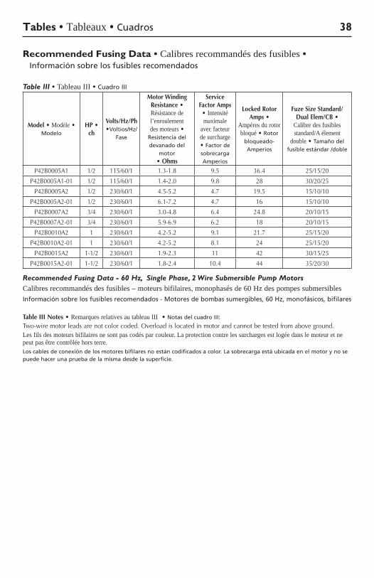
Recommended Fusing Data • Calibres recommandés des fusibles • Información sobre los fusibles recomendados
Table III • Tableau III • Cuadro III
Model • Modèle • Modelo
HP • ch
Volts/Hz/Ph •Voltios/Hz/
Fase
Motor Winding Resistance • Résistance de l’enroulement des moteurs •
Resistencia del devanado del
motor • Ohms
Service Factor Amps • Intensité maximale
avec facteur de surcharge • Factor de sobrecarga Amperios
Locked Rotor Amps •
Ampères du rotor bloqué • Rotor
bloqueado-Amperios
Fuze Size Standard/ Dual Elem/CB •
Calibre des fusibles standard/A élement
double • Tamaño del fusible estándar /doble
P42B0005A1 1/2 115/60/1 1.3-1.8 9.5 36.4 25/15/20
P42B0005A1-01 1/2 115/60/1 1.4-2.0 9.8 28 30/20/25
P42B0005A2 1/2 230/60/1 4.5-5.2 4.7 19.5 15/10/10
P42B0005A2-01 1/2 230/60/1 6.1-7.2 4.7 16 15/10/10
P42B0007A2 3/4 230/60/1 3.0-4.8 6.4 24.8 20/10/15
P42B0007A2-01 3/4 230/60/1 5.9-6.9 6.2 18 20/10/15
P42B0010A2 1 230/60/1 4.2-5.2 9.1 21.7 25/15/20
P42B0010A2-01 1 230/60/1 4.2-5.2 8.1 24 25/15/20
P42B0015A2 1-1/2 230/60/1 1.9-2.3 11 42 30/15/25
P42B0015A2-01 1-1/2 230/60/1 1.8-2.4 10.4 44 35/20/30
Recommended Fusing Data - 60 Hz, Single Phase, 2 Wire Submersible Pump MotorsCalibres recommandés des fusibles – moteurs bifilaires, monophasés de 60 Hz des pompes submersiblesInformación sobre los fusibles recomendados - Motores de bombas sumergibles, 60 Hz, monofásicos, bifilares
Table III Notes • Remarques relatives au tableau III • Notas del cuadro III:
Two-wire motor leads are not color coded. Overload is located in motor and cannot be tested from above ground.Les fils des moteurs bifilaires ne sont pas codés par couleur. La protection contre les surcharges est logée dans le moteur et ne peut pas être contrôlée hors terre.Los cables de conexión de los motores bifilares no están codificados a color. La sobrecarga está ubicada en el motor y no se puede hacer una prueba de la misma desde la superficie.
Tables • Tableaux • Cuadros 38
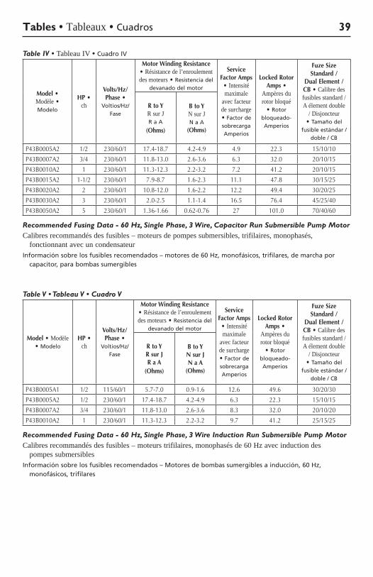
Table IV • Tableau IV • Cuadro IV
Model • Modèle • Modelo
HP • ch
Volts/Hz/Phase •
Voltios/Hz/Fase
Motor Winding Resistance • Résistance de l’enroulement des moteurs • Resistencia del
devanado del motor
Service Factor Amps • Intensité maximale
avec facteur de surcharge • Factor de sobrecarga Amperios
Locked Rotor Amps •
Ampères du rotor bloqué
• Rotor bloqueado-Amperios
Fuze Size Standard /
Dual Element /CB • Calibre des fusibles standard / A élement double
/ Disjoncteur • Tamaño del
fusible estándar /doble / CB
R to Y R sur J R a A
(Ohms)
B to Y N sur J N a A
(Ohms)
P43B0005A2 1/2 230/60/1 17.4-18.7 4.2-4.9 4.9 22.3 15/10/10
P43B0007A2 3/4 230/60/1 11.8-13.0 2.6-3.6 6.3 32.0 20/10/15
P43B0010A2 1 230/60/1 11.3-12.3 2.2-3.2 7.2 41.2 20/10/15
P43B0015A2 1-1/2 230/60/1 7.9-8.7 1.6-2.3 11.1 47.8 30/15/25
P43B0020A2 2 230/60/1 10.8-12.0 1.6-2.2 12.2 49.4 30/20/25
P43B0030A2 3 230/60/1 2.0-2.5 1.1-1.4 16.5 76.4 45/25/40
P43B0050A2 5 230/60/1 1.36-1.66 0.62-0.76 27 101.0 70/40/60
Recommended Fusing Data - 60 Hz, Single Phase, 3 Wire, Capacitor Run Submersible Pump MotorCalibres recommandés des fusibles – moteurs de pompes submersibles, trifilaires, monophasés,
fonctionnant avec un condensateurInformación sobre los fusibles recomendados – motores de 60 Hz, monofásicos, trifilares, de marcha por
capacitor, para bombas sumergibles
Table V • Tableau V • Cuadro V
Model • Modèle • Modelo
HP • ch
Volts/Hz/Phase •
Voltios/Hz/Fase
Motor Winding Resistance • Résistance de l’enroulement des moteurs • Resistencia del
devanado del motor
Service Factor Amps • Intensité maximale
avec facteur de surcharge • Factor de sobrecarga Amperios
Locked Rotor Amps •
Ampères du rotor bloqué
• Rotor bloqueado-Amperios
Fuze Size Standard /
Dual Element /CB • Calibre des fusibles standard / A élement double
/ Disjoncteur • Tamaño del
fusible estándar /doble / CB
R to Y R sur J R a A
(Ohms)
B to Y N sur J N a A
(Ohms)
P43B0005A1 1/2 115/60/1 5.7-7.0 0.9-1.6 12.6 49.6 30/20/30
P43B0005A2 1/2 230/60/1 17.4-18.7 4.2-4.9 6.3 22.3 15/10/15
P43B0007A2 3/4 230/60/1 11.8-13.0 2.6-3.6 8.3 32.0 20/10/20
P43B0010A2 1 230/60/1 11.3-12.3 2.2-3.2 9.7 41.2 25/15/25
Recommended Fusing Data - 60 Hz, Single Phase, 3 Wire Induction Run Submersible Pump MotorCalibres recommandés des fusibles – moteurs trifilaires, monophasés de 60 Hz avec induction des
pompes submersiblesInformación sobre los fusibles recomendados – Motores de bombas sumergibles a inducción, 60 Hz,
monofásicos, trifilares
Tables • Tableaux • Cuadros 39
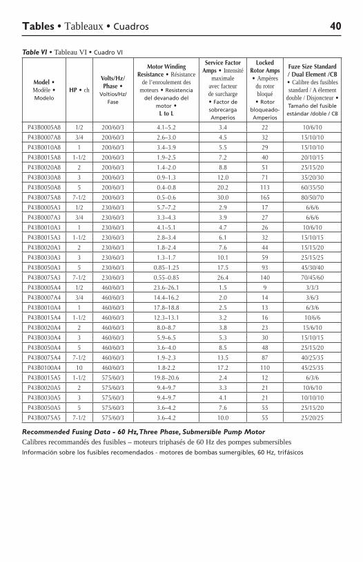
Table VI • Tableau VI • Cuadro VI
Model • Modèle • Modelo
HP • ch
Volts/Hz/Phase •
Voltios/Hz/Fase
Motor Winding Resistance • Résistance
de l’enroulement des moteurs • Resistencia
del devanado del motor •
L to L
Service Factor Amps • Intensité
maximale avec facteur de surcharge • Factor de sobrecarga Amperios
Locked Rotor Amps • Ampères
du rotor bloqué
• Rotor bloqueado-Amperios
Fuze Size Standard / Dual Element /CB • Calibre des fusibles standard / A élement
double / Disjoncteur • Tamaño del fusible estándar /doble / CB
P43B0005A8 1/2 200/60/3 4.1–5.2 3.4 22 10/6/10
P43B0007A8 3/4 200/60/3 2.6–3.0 4.5 32 15/10/10
P43B0010A8 1 200/60/3 3.4–3.9 5.5 29 15/10/10
P43B0015A8 1-1/2 200/60/3 1.9–2.5 7.2 40 20/10/15
P43B0020A8 2 200/60/3 1.4–2.0 8.8 51 25/15/20
P43B0030A8 3 200/60/3 0.9–1.3 12.0 71 35/20/30
P43B0050A8 5 200/60/3 0.4–0.8 20.2 113 60/35/50
P43B0075A8 7-1/2 200/60/3 0.5–0.6 30.0 165 80/50/70
P43B0005A3 1/2 230/60/3 5.7–7.2 2.9 17 6/6/6
P43B0007A3 3/4 230/60/3 3.3–4.3 3.9 27 6/6/6
P43B0010A3 1 230/60/3 4.1–5.1 4.7 26 10/6/10
P43B0015A3 1-1/2 230/60/3 2.8–3.4 6.1 32 15/10/15
P43B0020A3 2 230/60/3 1.8–2.4 7.6 44 15/15/20
P43B0030A3 3 230/60/3 1.3–1.7 10.1 59 25/15/25
P43B0050A3 5 230/60/3 0.85–1.25 17.5 93 45/30/40
P43B0075A3 7-1/2 230/60/3 0.55–0.85 26.4 140 70/45/60
P43B0005A4 1/2 460/60/3 23.6–26.1 1.5 9 3/3/3
P43B0007A4 3/4 460/60/3 14.4–16.2 2.0 14 3/6/3
P43B0010A4 1 460/60/3 17.8–18.8 2.5 13 6/3/6
P43B0015A4 1-1/2 460/60/3 12.3–13.1 3.2 16 10/6/6
P43B0020A4 2 460/60/3 8.0–8.7 3.8 23 15/6/10
P43B0030A4 3 460/60/3 5.9–6.5 5.3 30 15/10/15
P43B0050A4 5 460/60/3 3.6–4.0 8.5 48 25/15/20
P43B0075A4 7-1/2 460/60/3 1.9–2.3 13.5 87 40/25/35
P43B0100A4 10 460/60/3 1.8-2.2 17.2 110 45/25/35
P43B0015A5 1-1/2 575/60/3 19.8–20.6 2.4 12 6/3/6
P43B0020A5 2 575/60/3 9.4–9.7 3.3 21 10/6/10
P43B0030A5 3 575/60/3 9.4–9.7 4.1 21 10/10/10
P43B0050A5 5 575/60/3 3.6–4.2 7.6 55 25/15/20
P43B0075A5 7-1/2 575/60/3 3.6–4.2 10.0 55 25/20/25
Recommended Fusing Data - 60 Hz, Three Phase, Submersible Pump MotorCalibres recommandés des fusibles – moteurs triphasés de 60 Hz des pompes submersiblesInformación sobre los fusibles recomendados - motores de bombas sumergibles, 60 Hz, trifásicos
Tables • Tableaux • Cuadros 40
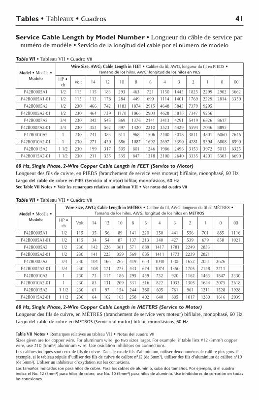
Service Cable Length by Model Number • Longueur du câble de service par numéro de modèle • Servicio de la longitud del cable por el número de modelo
Table VII • Tableau VII • Cuadro VII
Model • Modèle • Modelo
Wire Size, AWG; Cable Length in FEET • Calibre du fil, AWG, longueur du fil en PIEDS • Tamaño de los hilos, AWG; longitud de los hilos en PIES
HP•ch Volt 14 12 10 8 6 4 3 2 1 0 00
P42B0005A1 1/2 115 115 183 293 463 721 1150 1445 1825 2299 2902 3662
P42B0005A1-01 1/2 115 112 178 284 449 699 1114 1401 1769 2229 2814 3350
P42B0005A2 1/2 230 466 742 1183 1874 2915 4648 5843 7379 9295
P42B0005A2-01 1/2 230 464 739 1178 1866 2903 4628 5818 7347 9256
P42B0007A2 3/4 230 342 545 869 1376 2141 3413 4291 5419 6826 8617
P42B0007A2-01 3/4 230 353 562 897 1420 2210 3523 4429 5594 7046 8895
P42B0010A2 1 230 241 383 611 968 1506 2400 3018 3811 4801 6060 7646
P42B0010A2-01 1 230 271 430 686 1087 1692 2697 3390 4281 5394 6808 8590
P42B0015A2 11/2 230 199 317 505 801 1246 1986 2496 3153 3972 5013 6325
P42B0015A2-01 11/2 230 211 335 535 847 1318 2100 2640 3335 4201 5303 6690
60 Hz, Single Phase, 2-Wire Copper Cable Length in FEET (Service to Motor)Longueur des fils de cuivre, en PIEDS (branchement de service vers moteur) bifilaire, monophasé, 60 HzLargo del cable de cobre en PIES (Servicio al motor) bifilar, monofásicos, 60 HzSee Table ViI Notes •Voir les remarques relatives au tableau VII •Ver notas del cuadro VII
Table VII • Tableau VII • Cuadro VII
Model • Modèle • Modelo
Wire Size, AWG; Cable Length in METERS • Calibre du fil, AWG, longueur du fil en MÈTRES • Tamaño de los hilos, AWG; longitud de los hilos en METROS
HP•ch Volt 14 12 10 8 6 4 3 2 1 0 00
P42B0005A1 1/2 115 35 56 89 141 220 350 441 556 701 885 1116
P42B0005A1-01 1/2 115 34 54 87 137 213 340 427 539 679 858 1021
P42B0005A2 1/2 230 142 226 361 571 889 1417 1781 2249 2833
P42B0005A2-01 1/2 230 141 225 359 569 885 1411 1773 2239 2821
P42B0007A2 3/4 230 104 166 265 419 653 1040 1308 1652 2081 2626
P42B0007A2-01 3/4 230 108 171 273 433 674 1074 1350 1705 2148 2711
P42B0010A2 1 230 73 117 186 295 459 732 920 1162 1463 1847 2330
P42B0010A2-01 1 230 83 131 209 331 516 822 1033 1305 1644 2075 2618
P42B0015A2 11/2 230 61 97 154 244 380 605 761 961 1211 1528 1928
P42B0015A2-01 11/2 230 64 102 163 258 402 640 805 1017 1280 1616 2039
60 Hz, Single Phase, 2-Wire Copper Cable Length in METERS (Service to Motor)Longueur des fils de cuivre, en MÈTRES (branchement de service vers moteur) bifilaire, monophasé, 60 HzLargo del cable de cobre en METROS (Servicio al motor) bifilar, monofásicos, 60 Hz
Table VII Notes • Remarques relatives au tableau VII • Notas del cuadro VII
Sizesgivenareforcopperwire.Foraluminumwire,gotwosizeslarger.Forexample,iftablelists#12(3mm²)copperwire,use#10(5mm²)aluminumwire.Useoxidationinhibitorsonconnections.Les calibres indiqués sont ceux de fils de cuivre. Dans le cas de fils d’aluminium, utiliser deux numéros de calibre plus gros. Par exemple, si le tableau stipule d’utiliser des fils de cuivre de calibre n°12 (de 3mm²), utiliser des fils d’aluminium de calibre n°10 (de 5mm²). Utiliser un inhibiteur d’oxydation sur les connexions. Los tamaños indicados son para hilos de cobre. Para los cables de aluminio, suba dos tamaños. Por ejemplo, si el cuadro indica el No. 12 (3mm²) para hilos de cobre, use No. 10 (5mm²) para hilos de aluminio. Use inhibidores de corrosión en todas las conexiones.
Tables • Tableaux • Cuadros 41
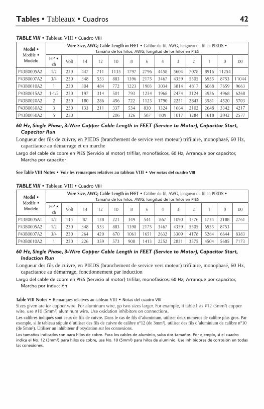
TABLE VIII • Tableau VIII • Cuadro VIII
Model • Modèle • Modelo
Wire Size, AWG; Cable Length in FEET • Calibre du fil, AWG, longueur du fil en PIEDS • Tamaño de los hilos, AWG; longitud de los hilos en PIES
HP•ch Volt 14 12 10 8 6 4 3 2 1 0 00
P43B0005A2 1/2 230 447 711 1135 1797 2796 4458 5604 7078 8916 11254
P43B0007A2 3/4 230 348 553 883 1396 2175 3467 4359 5505 6935 8753 11044
P43B0010A2 1 230 304 484 772 1223 1903 3034 3814 4817 6068 7659 9663
P43B0015A2 1-1/2 230 197 314 501 793 1234 1968 2474 3124 3936 4968 6268
P43B0020A2 2 230 180 286 456 722 1123 1790 2251 2843 3581 4520 5703
P43B0030A2 3 230 133 211 337 534 830 1324 1664 2102 2648 3342 4217
P43B0050A2 5 230 206 326 507 809 1017 1284 1618 2042 2577
60 Hz, Single Phase, 3-Wire Copper Cable Length in FEET (Service to Motor), Capacitor Start, Capacitor Run
Longueur des fils de cuivre, en PIEDS (branchement de service vers moteur) trifilaire, monophasé, 60 Hz, capacitance au démarrage et en marche
Largo del cable de cobre en PIES (Servicio al motor) trifilar, monofásicos, 60 Hz, Arranque por capacitor, Marcha por capacitor
See Table VIII Notes •Voir les remarques relatives au tableau VIII •Ver notas del cuadro VIII
TABLE VIII • Tableau VIII • Cuadro VIII
Model • Modèle • Modelo
Wire Size, AWG; Cable Length in FEET • Calibre du fil, AWG, longueur du fil en PIEDS • Tamaño de los hilos, AWG; longitud de los hilos en PIES
HP•ch Volt 14 12 10 8 6 4 3 2 1 0 00
P43B0005A1 1/2 115 87 138 221 349 544 867 1090 1376 1734 2188 2761
P43B0005A2 1/2 230 348 553 883 1398 2175 3467 4359 5505 6935 8753
P43B0007A2 3/4 230 264 420 670 1061 1651 2632 3309 4178 5264 6644 8383
P43B0010A2 1 230 226 359 573 908 1413 2252 2831 3575 4504 5685 7173
60 Hz, Single Phase, 3-Wire Copper Cable Length in FEET (Service to Motor), Capacitor Start, Induction Run
Longueur des fils de cuivre, en PIEDS (branchement de service vers moteur) trifilaire, monophasé, 60 Hz, capacitance au démarrage, fonctionnement par induction
Largo del cable de cobre en PIES (Servicio al motor) trifilar, monofásicos, 60 Hz, Arranque por capacitor, Marcha por inducción
Table VIII Notes • Remarques relatives au tableau VIII • Notas del cuadro VIII
Sizesgivenareforcopperwire.Foraluminumwire,gotwosizeslarger.Forexample,iftablelists#12(3mm²)copperwire,use#10(5mm²)aluminumwire.Useoxidationinhibitorsonconnections.Les calibres indiqués sont ceux de fils de cuivre. Dans le cas de fils d’aluminium, utiliser deux numéros de calibre plus gros. Par exemple, si le tableau stipule d’utiliser des fils de cuivre de calibre n°12 (de 3mm²), utiliser des fils d’aluminium de calibre n°10 (de 5mm²). Utiliser un inhibiteur d’oxydation sur les connexions. Los tamaños indicados son para hilos de cobre. Para los cables de aluminio, suba dos tamaños. Por ejemplo, si el cuadro indica el No. 12 (3mm²) para hilos de cobre, use No. 10 (5mm²) para hilos de aluminio. Use inhibidores de corrosión en todas las conexiones.
Tables • Tableaux • Cuadros 42
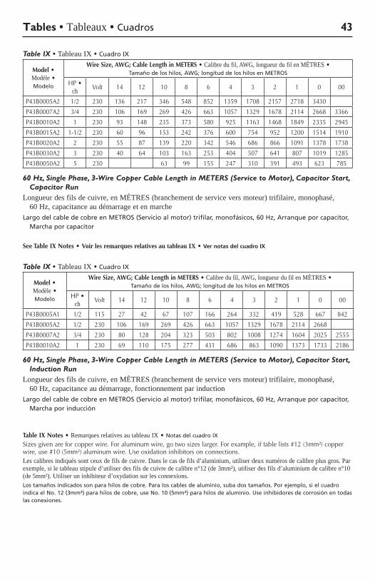
Table IX • Tableau IX • Cuadro IX
Model • Modèle • Modelo
Wire Size, AWG; Cable Length in METERS • Calibre du fil, AWG, longueur du fil en MÈTRES • Tamaño de los hilos, AWG; longitud de los hilos en METROS
HP•ch Volt 14 12 10 8 6 4 3 2 1 0 00
P43B0005A2 1/2 230 136 217 346 548 852 1359 1708 2157 2718 3430
P43B0007A2 3/4 230 106 169 269 426 663 1057 1329 1678 2114 2668 3366
P43B0010A2 1 230 93 148 235 373 580 925 1163 1468 1849 2335 2945
P43B0015A2 1-1/2 230 60 96 153 242 376 600 754 952 1200 1514 1910
P43B0020A2 2 230 55 87 139 220 342 546 686 866 1091 1378 1738
P43B0030A2 3 230 40 64 103 163 253 404 507 641 807 1019 1285
P43B0050A2 5 230 63 99 155 247 310 391 493 623 785
60 Hz, Single Phase, 3-Wire Copper Cable Length in METERS (Service to Motor), Capacitor Start, Capacitor Run
Longueur des fils de cuivre, en MÈTRES (branchement de service vers moteur) trifilaire, monophasé, 60 Hz, capacitance au démarrage et en marche
Largo del cable de cobre en METROS (Servicio al motor) trifilar, monofásicos, 60 Hz, Arranque por capacitor, Marcha por capacitor
See Table IX Notes •Voir les remarques relatives au tableau IX •Ver notas del cuadro IX
Table IX • Tableau IX • Cuadro IX
Model • Modèle • Modelo
Wire Size, AWG; Cable Length in METERS • Calibre du fil, AWG, longueur du fil en MÈTRES • Tamaño de los hilos, AWG; longitud de los hilos en METROS
HP•ch Volt 14 12 10 8 6 4 3 2 1 0 00
P43B0005A1 1/2 115 27 42 67 107 166 264 332 419 528 667 842
P43B0005A2 1/2 230 106 169 269 426 663 1057 1329 1678 2114 2668
P43B0007A2 3/4 230 80 128 204 323 503 802 1008 1274 1604 2025 2555
P43B0010A2 1 230 69 110 175 277 431 686 863 1090 1373 1733 2186
60 Hz, Single Phase, 3-Wire Copper Cable Length in METERS (Service to Motor), Capacitor Start, Induction Run
Longueur des fils de cuivre, en MÈTRES (branchement de service vers moteur) trifilaire, monophasé, 60 Hz, capacitance au démarrage, fonctionnement par induction
Largo del cable de cobre en METROS (Servicio al motor) trifilar, monofásicos, 60 Hz, Arranque por capacitor, Marcha por inducción
Table IX Notes • Remarques relatives au tableau IX • Notas del cuadro IX
Sizesgivenareforcopperwire.Foraluminumwire,gotwosizeslarger.Forexample,iftablelists#12(3mm²)copperwire,use#10(5mm²)aluminumwire.Useoxidationinhibitorsonconnections.Les calibres indiqués sont ceux de fils de cuivre. Dans le cas de fils d’aluminium, utiliser deux numéros de calibre plus gros. Par exemple, si le tableau stipule d’utiliser des fils de cuivre de calibre n°12 (de 3mm²), utiliser des fils d’aluminium de calibre n°10 (de 5mm²). Utiliser un inhibiteur d’oxydation sur les connexions. Los tamaños indicados son para hilos de cobre. Para los cables de aluminio, suba dos tamaños. Por ejemplo, si el cuadro indica el No. 12 (3mm²) para hilos de cobre, use No. 10 (5mm²) para hilos de aluminio. Use inhibidores de corrosión en todas las conexiones.
Tables • Tableaux • Cuadros 43
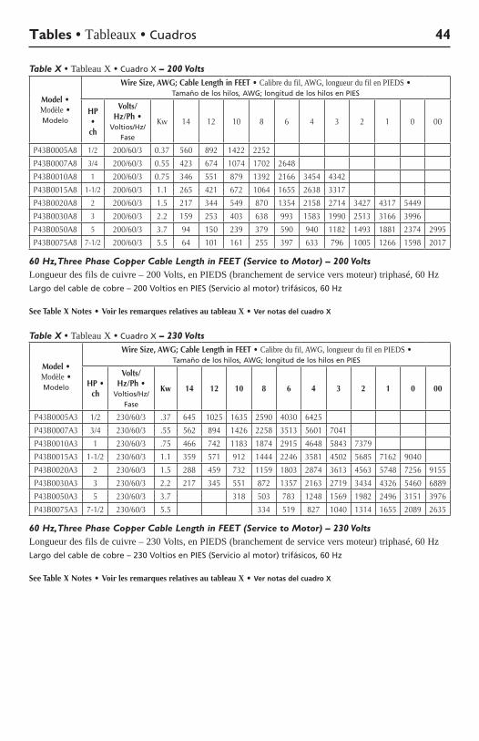
Table X • Tableau X • Cuadro X – 200 Volts
Model • Modèle • Modelo
Wire Size, AWG; Cable Length in FEET • Calibre du fil, AWG, longueur du fil en PIEDS • Tamaño de los hilos, AWG; longitud de los hilos en PIES
HP • ch
Volts/Hz/Ph •
Voltios/Hz/Fase
Kw 14 12 10 8 6 4 3 2 1 0 00
P43B0005A8 1/2 200/60/3 0.37 560 892 1422 2252
P43B0007A8 3/4 200/60/3 0.55 423 674 1074 1702 2648
P43B0010A8 1 200/60/3 0.75 346 551 879 1392 2166 3454 4342
P43B0015A8 1-1/2 200/60/3 1.1 265 421 672 1064 1655 2638 3317
P43B0020A8 2 200/60/3 1.5 217 344 549 870 1354 2158 2714 3427 4317 5449
P43B0030A8 3 200/60/3 2.2 159 253 403 638 993 1583 1990 2513 3166 3996
P43B0050A8 5 200/60/3 3.7 94 150 239 379 590 940 1182 1493 1881 2374 2995
P43B0075A8 7-1/2 200/60/3 5.5 64 101 161 255 397 633 796 1005 1266 1598 2017
60 Hz, Three Phase Copper Cable Length in FEET (Service to Motor) – 200 VoltsLongueur des fils de cuivre – 200 Volts, en PIEDS (branchement de service vers moteur) triphasé, 60 HzLargo del cable de cobre – 200 Voltios en PIES (Servicio al motor) trifásicos, 60 Hz
See Table X Notes •Voir les remarques relatives au tableau X •Ver notas del cuadro X
Table X • Tableau X • Cuadro X – 230 Volts
Model • Modèle • Modelo
Wire Size, AWG; Cable Length in FEET • Calibre du fil, AWG, longueur du fil en PIEDS • Tamaño de los hilos, AWG; longitud de los hilos en PIES
HP • ch
Volts/Hz/Ph •
Voltios/Hz/Fase
Kw 14 12 10 8 6 4 3 2 1 0 00
P43B0005A3 1/2 230/60/3 .37 645 1025 1635 2590 4030 6425
P43B0007A3 3/4 230/60/3 .55 562 894 1426 2258 3513 5601 7041
P43B0010A3 1 230/60/3 .75 466 742 1183 1874 2915 4648 5843 7379
P43B0015A3 1-1/2 230/60/3 1.1 359 571 912 1444 2246 3581 4502 5685 7162 9040
P43B0020A3 2 230/60/3 1.5 288 459 732 1159 1803 2874 3613 4563 5748 7256 9155
P43B0030A3 3 230/60/3 2.2 217 345 551 872 1357 2163 2719 3434 4326 5460 6889
P43B0050A3 5 230/60/3 3.7 318 503 783 1248 1569 1982 2496 3151 3976
P43B0075A3 7-1/2 230/60/3 5.5 334 519 827 1040 1314 1655 2089 2635
60 Hz, Three Phase Copper Cable Length in FEET (Service to Motor) – 230 VoltsLongueur des fils de cuivre – 230 Volts, en PIEDS (branchement de service vers moteur) triphasé, 60 HzLargo del cable de cobre – 230 Voltios en PIES (Servicio al motor) trifásicos, 60 Hz
See Table X Notes •Voir les remarques relatives au tableau X •Ver notas del cuadro X
Tables • Tableaux • Cuadros 44
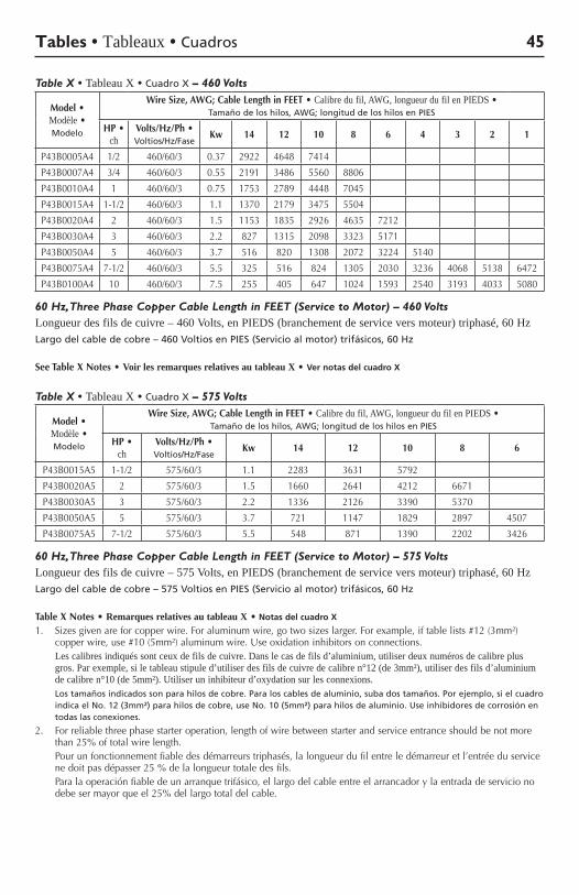
Table X • Tableau X • Cuadro X – 460 Volts
Model • Modèle • Modelo
Wire Size, AWG; Cable Length in FEET • Calibre du fil, AWG, longueur du fil en PIEDS • Tamaño de los hilos, AWG; longitud de los hilos en PIES
HP • ch
Volts/Hz/Ph • Voltios/Hz/Fase
Kw 14 12 10 8 6 4 3 2 1
P43B0005A4 1/2 460/60/3 0.37 2922 4648 7414
P43B0007A4 3/4 460/60/3 0.55 2191 3486 5560 8806
P43B0010A4 1 460/60/3 0.75 1753 2789 4448 7045
P43B0015A4 1-1/2 460/60/3 1.1 1370 2179 3475 5504
P43B0020A4 2 460/60/3 1.5 1153 1835 2926 4635 7212
P43B0030A4 3 460/60/3 2.2 827 1315 2098 3323 5171
P43B0050A4 5 460/60/3 3.7 516 820 1308 2072 3224 5140
P43B0075A4 7-1/2 460/60/3 5.5 325 516 824 1305 2030 3236 4068 5138 6472
P43B0100A4 10 460/60/3 7.5 255 405 647 1024 1593 2540 3193 4033 5080
60 Hz, Three Phase Copper Cable Length in FEET (Service to Motor) – 460 VoltsLongueur des fils de cuivre – 460 Volts, en PIEDS (branchement de service vers moteur) triphasé, 60 HzLargo del cable de cobre – 460 Voltios en PIES (Servicio al motor) trifásicos, 60 Hz
See Table X Notes •Voir les remarques relatives au tableau X •Ver notas del cuadro X
Table X • Tableau X • Cuadro X – 575 Volts
Model • Modèle • Modelo
Wire Size, AWG; Cable Length in FEET • Calibre du fil, AWG, longueur du fil en PIEDS • Tamaño de los hilos, AWG; longitud de los hilos en PIES
HP • ch
Volts/Hz/Ph • Voltios/Hz/Fase
Kw 14 12 10 8 6
P43B0015A5 1-1/2 575/60/3 1.1 2283 3631 5792
P43B0020A5 2 575/60/3 1.5 1660 2641 4212 6671
P43B0030A5 3 575/60/3 2.2 1336 2126 3390 5370
P43B0050A5 5 575/60/3 3.7 721 1147 1829 2897 4507
P43B0075A5 7-1/2 575/60/3 5.5 548 871 1390 2202 3426
60 Hz, Three Phase Copper Cable Length in FEET (Service to Motor) – 575 VoltsLongueur des fils de cuivre – 575 Volts, en PIEDS (branchement de service vers moteur) triphasé, 60 HzLargo del cable de cobre – 575 Voltios en PIES (Servicio al motor) trifásicos, 60 Hz
Table X Notes•Remarques relatives au tableau X• Notas del cuadro X
1. Sizesgivenareforcopperwire.Foraluminumwire,gotwosizeslarger.Forexample,iftablelists#12(3mm²)copperwire,use#10(5mm²)aluminumwire.Useoxidationinhibitorsonconnections.
Les calibres indiqués sont ceux de fils de cuivre. Dans le cas de fils d’aluminium, utiliser deux numéros de calibre plus gros. Par exemple, si le tableau stipule d’utiliser des fils de cuivre de calibre n°12 (de 3mm²), utiliser des fils d’aluminium de calibre n°10 (de 5mm²). Utiliser un inhibiteur d’oxydation sur les connexions.
Los tamaños indicados son para hilos de cobre. Para los cables de aluminio, suba dos tamaños. Por ejemplo, si el cuadro indica el No. 12 (3mm²) para hilos de cobre, use No. 10 (5mm²) para hilos de aluminio. Use inhibidores de corrosión en todas las conexiones.
2. For reliable three phase starter operation, length of wire between starter and service entrance should be not more than25%oftotalwire length.
Pour un fonctionnement fiable des démarreurs triphasés, la longueur du fil entre le démarreur et l’entrée du service nedoitpasdépasser25%delalongueurtotaledesfils.
Paralaoperaciónfiabledeunarranquetrifásico,ellargodelcableentreelarrancadorylaentradadeservicionodebesermayorqueel25%dellargototaldelcable.
Tables • Tableaux • Cuadros 45
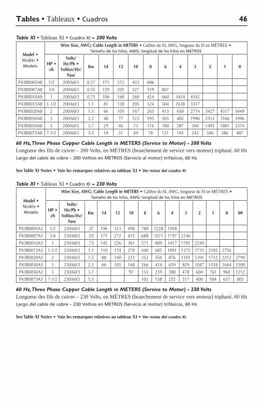
Table XI • Tableau XI • Cuadro XI – 200 Volts
Model • Modèle • Modelo
Wire Size, AWG; Cable Length in METERS • Calibre du fil, AWG, longueur du fil en MÈTRES • Tamaño de los hilos, AWG; longitud de los hilos en METROS
HP • ch
Volts/Hz/Ph •
Voltios/Hz/Fase
Kw 14 12 10 8 6 4 3 2 1 0
P43B0005A8 1/2 200/60/3 0.37 171 272 433 686
P43B0007A8 3/4 200/60/3 0.55 129 205 327 519 807
P43B0010A8 1 200/60/3 0.75 106 168 268 424 660 3454 4342
P43B0015A8 1-1/2 200/60/3 1.1 81 128 205 324 504 2638 3317
P43B0020A8 2 200/60/3 1.5 66 105 167 265 413 658 2714 3427 4317 5449
P43B0030A8 3 200/60/3 2.2 48 77 123 195 303 482 1990 2513 3166 3996
P43B0050A8 5 200/60/3 3.7 29 46 73 116 180 287 360 1493 1881 2374
P43B0075A8 7-1/2 200/60/3 5.5 19 31 49 78 121 193 243 306 386 487
60 Hz, Three Phase Copper Cable Length in METERS (Service to Motor) - 200 VoltsLongueur des fils de cuivre – 200 Volts, en MÈTRES (branchement de service vers moteur) triphasé, 60 HzLargo del cable de cobre – 200 Voltios en METROS (Servicio al motor) trifásicos, 60 Hz
See Table XI Notes •Voir les remarques relatives au tableau XI •Ver notas del cuadro XI
Table XI • Tableau XI • Cuadro XI – 230 Volts
Model • Modèle • Modelo
Wire Size, AWG; Cable Length in METERS • Calibre du fil, AWG, longueur du fil en MÈTRES • Tamaño de los hilos, AWG; longitud de los hilos en METROS
HP • ch
Volts/Hz/Ph •
Voltios/Hz/Fase
Kw 14 12 10 8 6 4 3 2 1 0 00
P43B0005A3 1/2 230/60/3 .37 196 313 498 789 1228 1958
P43B0007A3 3/4 230/60/3 .55 171 272 435 688 1071 1797 2146
P43B0010A3 1 230/60/3 .75 142 226 361 571 889 1417 1781 2249
P43B0015A3 1-1/2 230/60/3 1.1 110 174 278 440 685 1091 1372 1733 2183 2756
P43B0020A3 2 230/60/3 1.5 88 140 223 353 550 876 1101 1391 1752 2212 2790
P43B0030A3 3 230/60/3 2.2 66 105 168 266 414 659 829 1047 1318 1664 2100
P43B0050A3 5 230/60/3 3.7 97 153 239 380 478 604 761 960 1212
P43B0075A3 7-1/2 230/60/3 5.5 102 158 252 317 400 504 637 803
60 Hz, Three Phase Copper Cable Length in METERS (Service to Motor) - 230 VoltsLongueur des fils de cuivre – 230 Volts, en MÈTRES (branchement de service vers moteur) triphasé, 60 HzLargo del cable de cobre – 230 Voltios en METROS (Servicio al motor) trifásicos, 60 Hz
See Table XI Notes •Voir les remarques relatives au tableau XI •Ver notas del cuadro XI
Tables • Tableaux • Cuadros 46
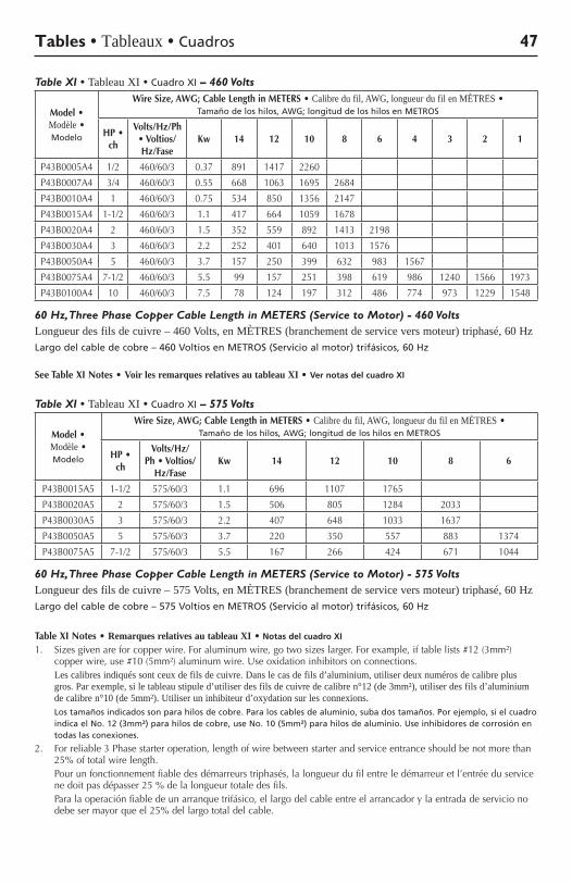
Table XI • Tableau XI • Cuadro XI – 460 Volts
Model • Modèle • Modelo
Wire Size, AWG; Cable Length in METERS • Calibre du fil, AWG, longueur du fil en MÈTRES • Tamaño de los hilos, AWG; longitud de los hilos en METROS
HP • ch
Volts/Hz/Ph • Voltios/Hz/Fase
Kw 14 12 10 8 6 4 3 2 1
P43B0005A4 1/2 460/60/3 0.37 891 1417 2260
P43B0007A4 3/4 460/60/3 0.55 668 1063 1695 2684
P43B0010A4 1 460/60/3 0.75 534 850 1356 2147
P43B0015A4 1-1/2 460/60/3 1.1 417 664 1059 1678
P43B0020A4 2 460/60/3 1.5 352 559 892 1413 2198
P43B0030A4 3 460/60/3 2.2 252 401 640 1013 1576
P43B0050A4 5 460/60/3 3.7 157 250 399 632 983 1567
P43B0075A4 7-1/2 460/60/3 5.5 99 157 251 398 619 986 1240 1566 1973
P43B0100A4 10 460/60/3 7.5 78 124 197 312 486 774 973 1229 1548
60 Hz, Three Phase Copper Cable Length in METERS (Service to Motor) - 460 VoltsLongueur des fils de cuivre – 460 Volts, en MÈTRES (branchement de service vers moteur) triphasé, 60 HzLargo del cable de cobre – 460 Voltios en METROS (Servicio al motor) trifásicos, 60 Hz
See Table XI Notes •Voir les remarques relatives au tableau XI •Ver notas del cuadro XI
Table XI • Tableau XI • Cuadro XI – 575 Volts
Model • Modèle • Modelo
Wire Size, AWG; Cable Length in METERS • Calibre du fil, AWG, longueur du fil en MÈTRES • Tamaño de los hilos, AWG; longitud de los hilos en METROS
HP • ch
Volts/Hz/Ph • Voltios/
Hz/FaseKw 14 12 10 8 6
P43B0015A5 1-1/2 575/60/3 1.1 696 1107 1765
P43B0020A5 2 575/60/3 1.5 506 805 1284 2033
P43B0030A5 3 575/60/3 2.2 407 648 1033 1637
P43B0050A5 5 575/60/3 3.7 220 350 557 883 1374
P43B0075A5 7-1/2 575/60/3 5.5 167 266 424 671 1044
60 Hz, Three Phase Copper Cable Length in METERS (Service to Motor) - 575 VoltsLongueur des fils de cuivre – 575 Volts, en MÈTRES (branchement de service vers moteur) triphasé, 60 HzLargo del cable de cobre – 575 Voltios en METROS (Servicio al motor) trifásicos, 60 Hz
Table XI Notes•Remarques relatives au tableau XI• Notas del cuadro XI
1. Sizesgivenareforcopperwire.Foraluminumwire,gotwosizeslarger.Forexample,iftablelists#12(3mm²)copperwire,use#10(5mm²)aluminumwire.Useoxidationinhibitorsonconnections.
Les calibres indiqués sont ceux de fils de cuivre. Dans le cas de fils d’aluminium, utiliser deux numéros de calibre plus gros. Par exemple, si le tableau stipule d’utiliser des fils de cuivre de calibre n°12 (de 3mm²), utiliser des fils d’aluminium de calibre n°10 (de 5mm²). Utiliser un inhibiteur d’oxydation sur les connexions.
Los tamaños indicados son para hilos de cobre. Para los cables de aluminio, suba dos tamaños. Por ejemplo, si el cuadro indica el No. 12 (3mm²) para hilos de cobre, use No. 10 (5mm²) para hilos de aluminio. Use inhibidores de corrosión en todas las conexiones.
2. For reliable 3 Phase starter operation, length of wire between starter and service entrance should be not more than 25%oftotalwire length.
Pour un fonctionnement fiable des démarreurs triphasés, la longueur du fil entre le démarreur et l’entrée du service nedoitpasdépasser25%delalongueurtotaledesfils.
Paralaoperaciónfiabledeunarranquetrifásico,ellargodelcableentreelarrancadorylaentradadeservicionodebesermayorqueel25%dellargototaldelcable.
Tables • Tableaux • Cuadros 47
Diagrams • Schémas • Diagramas 48
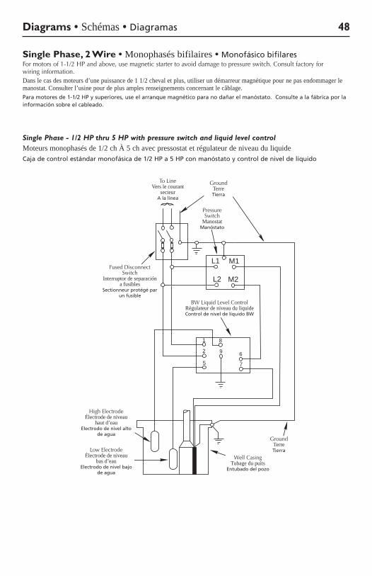
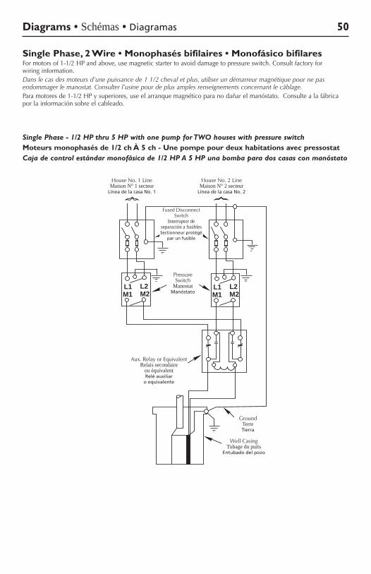
Single Phase, 2 Wire • Monophasés bifilaires • Monofásico bifilaresFormotorsof1-1/2HPandabove,usemagneticstartertoavoiddamagetopressureswitch.Consultfactoryforwiring information.Dans le cas des moteurs d’une puissance de 1 1/2 cheval et plus, utiliser un démarreur magnétique pour ne pas endommager le manostat. Consulter l’usine pour de plus amples renseignements concernant le câblage.Para motores de 1-1/2 HP y superiores, use el arranque magnético para no dañar el manóstato. Consulte a la fábrica por la información sobre el cableado.
Single Phase - 1/2 HP thru 5 HP with pressure switch and liquid level controlMoteurs monophasés de 1/2 ch À 5 ch avec pressostat et régulateur de niveau du liquideCaja de control estándar monofásica de 1/2 HP a 5 HP con manóstato y control de nivel de líquido
WellCasing
Ground
FusedDisconnect
Switch
To LineGround
1
2
5
8
9 6
7
HighElectrode
LowElectrode
BW LiquidLevel Control
L1 M1
L2 M2
PressureSwitch
363 0994
Pressure Switch
Manostat Manóstato
High Electrode Électrode de niveau
haut d’eau Electrodo de nivel alto
de agua
Low Electrode Électrode de niveau
bas d’eau Electrodo de nivel bajo
de agua
BWLiquidLevelControl Régulateur de niveau du liquide Control de nivel de líquido BW
To Line Vers le courant
secteur A la línea
Ground Terre Tierra
Fused Disconnect Switch
Interruptor de separación a fusibles
Sectionneur protégé par un fusible
Ground Terre Tierra
Well Casing Tubage du puits
Entubado del pozo
Diagrams • Schémas • Diagramas 49
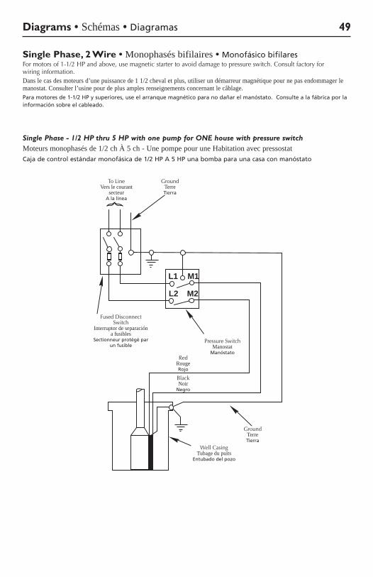
Single Phase, 2 Wire • Monophasés bifilaires • Monofásico bifilaresFormotorsof1-1/2HPandabove,usemagneticstartertoavoiddamagetopressureswitch.Consultfactoryforwiring information.Dans le cas des moteurs d’une puissance de 1 1/2 cheval et plus, utiliser un démarreur magnétique pour ne pas endommager le manostat. Consulter l’usine pour de plus amples renseignements concernant le câblage.Para motores de 1-1/2 HP y superiores, use el arranque magnético para no dañar el manóstato. Consulte a la fábrica por la información sobre el cableado.
Single Phase - 1/2 HP thru 5 HP with one pump for ONE house with pressure switchMoteurs monophasés de 1/2 ch À 5 ch - Une pompe pour une Habitation avec pressostatCaja de control estándar monofásica de 1/2 HP A 5 HP una bomba para una casa con manóstato
L1 M1
M2L2
FusedDisconnect
Switch
To Line Ground
Red
Black
PressureSwitch
WellCasing
Ground(Green)
360 0893
Red Rouge Rojo
Black Noir
Negro
Pressure Switch Manostat
Manóstato
To Line Vers le courant
secteur A la línea
Ground Terre Tierra
Ground Terre Tierra
Fused Disconnect Switch
Interruptor de separación a fusibles
Sectionneur protégé par un fusible
Well Casing Tubage du puits
Entubado del pozo
Diagrams • Schémas • Diagramas 50
Single Phase, 2 Wire • Monophasés bifilaires • Monofásico bifilaresFormotorsof1-1/2HPandabove,usemagneticstartertoavoiddamagetopressureswitch.Consultfactoryforwiring information.Dans le cas des moteurs d’une puissance de 1 1/2 cheval et plus, utiliser un démarreur magnétique pour ne pas endommager le manostat. Consulter l’usine pour de plus amples renseignements concernant le câblage.Paramotoresde1-1/2HPysuperiores,useelarranquemagnéticoparanodañarelmanóstato.Consultealafábricapor la información sobre el cableado.
Single Phase - 1/2 HP thru 5 HP with one pump for TWO houses with pressure switchMoteurs monophasés de 1/2 ch À 5 ch - Une pompe pour deux habitations avec pressostatCaja de control estándar monofásica de 1/2 HP A 5 HP una bomba para dos casas con manóstato
WellCasing
Ground
LineLine
L1M1 M2
L2 L1M1 M2
L2
FusedDisconnect
Switch
PressureSwitch
Aux. Relayor Equivalent
House No. 1 House No. 2
3109 1197
Aux.RelayorEquivalent Relais secondaire
ou équivalent Relé auxiliar
o equivalente
HouseNo.1Line Maison N° 1 secteur
Línea de la casa No. 1
HouseNo.2Line Maison N° 2 secteur
Línea de la casa No. 2
Pressure Switch
Manostat Manóstato
Ground Terre Tierra
Fused Disconnect Switch
Interruptor de separación a fusibles Sectionneur protégé
par un fusible
Well Casing Tubage du puits
Entubado del pozo
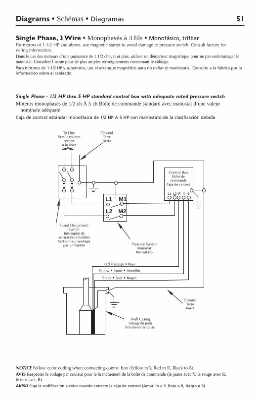
Diagrams • Schémas • Diagramas 51
Single Phase, 3 Wire • Monophasés à 3 fils • Monofásico, trifilarFormotorsof1-1/2HPandabove,usemagneticstartertoavoiddamagetopressureswitch.Consultfactoryforwiring information.Dans le cas des moteurs d’une puissance de 1 1/2 cheval et plus, utiliser un démarreur magnétique pour ne pas endommager le manostat. Consulter l’usine pour de plus amples renseignements concernant le câblage.Para motores de 1-1/2 HP y superiores, use el arranque magnético para no dañar el manóstato. Consulte a la fábrica por la información sobre el cableado.
Single Phase - 1/2 HP thru 5 HP standard control box with adequate rated pressure switchMoteurs monophasés de 1/2 ch À 5 ch Boîte de commande standard avec manostat d’une valeur
nominale adéquateCaja de control estándar monofásica de 1/2 HP A 5 HP con manóstato de la clasificación debida
NOTICE Follow color coding when connecting control box (Yellow to Y, Red to R, Black to B).AVIS Respecter le codage par couleur pour le branchement de la boîte de commande (le jaune avec Y, le rouge avec R, le noir avec B).AVISO Siga la codificación a color cuando conecte la caja de control (Amarillo a Y, Rojo a R, Negro a B)
L1 M1
M2L2
CONTROL
BOX
L1 L2 R Y B
FusedDisconnect
Switch
To Line Ground
RedYellowBlack
PressureSwitch
WellCasing
Ground
355 0893
Yellow•Jaune•Amarillo
Red•Rouge•Rojo
Black•Noir•Negro
Pressure Switch Manostat
Manóstato
To Line Vers le courant
secteur A la línea
Ground Terre Tierra
Ground Terre Tierra
Fused Disconnect Switch
Interruptor de separación a fusibles Sectionneur protégé
par un fusible
Well Casing Tubage du puits
Entubado del pozo
Control Box Boîte de
commande Caja de control
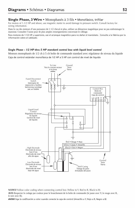
NOTICE Follow color coding when connecting control box (Yellow to Y, Red to R, Black to B).AVIS Respecter le codage par couleur pour le branchement de la boîte de commande (le jaune avec Y, le rouge avec R, le noir avec B).AVISO Siga la codificación a color cuando conecte la caja de control (Amarillo a Y, Rojo a R, Negro a B)
Diagrams • Schémas • Diagramas 52
Single Phase - 1/2 HP thru 5 HP standard control box with liquid level controlMoteurs monophasés de 1/2 ch à 5 ch boîte de commande standard avec régulateur de niveau du liquideCaja de control estándar monofásica de 1/2 HP a 5 HP con control de nivel de líquido
Single Phase, 3 Wire • Monophasés à 3 fils • Monofásico, trifilarFormotorsof1-1/2HPandabove,usemagneticstartertoavoiddamagetopressureswitch.Consultfactoryforwiring information.Dans le cas des moteurs d’une puissance de 1 1/2 cheval et plus, utiliser un démarreur magnétique pour ne pas endommager le manostat. Consulter l’usine pour de plus amples renseignements concernant le câblage.Para motores de 1-1/2 HP y superiores, use el arranque magnético para no dañar el manóstato. Consulte a la fábrica por la información sobre el cableado.
Black
RedYellow
WellCasing
Ground
ControlBox
L1 L2 R Y B
FusedDisconnect
Switch
To Line Ground
6
7
1
2
5
8
9
HighElectrode
LowElectrode
LiquidLevel
Control
353 0893
To Line Vers le courant secteur
A la línea
Ground Terre Tierra
Fused Disconnect Switch
Interruptor de separación a fusibles Sectionneur protégé
par un fusible Control Box Boîte de
commande Caja de control
High Electrode Électrode de niveau
haut d’eau Electrodo de nivel
alto de agua
Low Electrode Électrode de niveau
bas d’eau Electrodo de nivel
bajo de agua
LiquidLevelControl
Régulateur de niveau du liquide
Control de nivel de líquido
Yellow•Jaune•Amarillo
Red•Rouge•Rojo
Black•Noir•Negro
Ground Terre Tierra
Well Casing Tubage du puits
Entubado del pozo
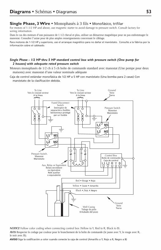
Diagrams • Schémas • Diagramas 53
Single Phase - 1/2 HP thru 5 HP standard control box with pressure switch (One pump for 2 houses) with adequate rated pressure switch
Moteurs monophasés de 1/2 ch à 5 ch boîte de commande standard avec manostat (Une pompe pour deux maisons) avec manostat d’une valeur nominale adéquate
Caja de control estándar monofásica de 1/2 HP a 5 HP con manóstato (Una bomba para 2 casas) Con manóstato de la clasificación debida.
Single Phase, 3 Wire • Monophasés à 3 fils • Monofásico, trifilarFormotorsof1-1/2HPandabove,usemagneticstartertoavoiddamagetopressureswitch.Consultfactoryforwiring information.Dans le cas des moteurs d’une puissance de 1 1/2 cheval et plus, utiliser un démarreur magnétique pour ne pas endommager le manostat. Consulter l’usine pour de plus amples renseignements concernant le câblage.Para motores de 1-1/2 HP y superiores, use el arranque magnético para no dañar el manóstato. Consulte a la fábrica por la información sobre el cableado.
CONTROLBOX
L1 L2 R Y B
RedYellow
Black
WellCasing
Ground
GroundTo LineTo Line
L1 M1
M2L2L1 M1
M2L2
FusedDisconnect
Switch
PressureSwitch
PressureSwitch
Aux. Relayor Equivalent
359 0893
Pressure Switch Manostat
Manóstato
Pressure Switch Manostat
Manóstato
To Line Vers le courant secteur
A la línea
To Line Vers le courant secteur
A la línea
Ground Terre Tierra
Fused Disconnect Switch
Interruptor de separación a fusibles Sectionneur protégé
par un fusible
Control Box Boîte de commande
Caja de control
Aux.RelayorEquivalent Relais secondaire
ou équivalent Relé auxiliar
o equivalente
Yellow•Jaune•Amarillo
Red•Rouge•Rojo
Black•Noir•Negro
Ground Terre TierraWell Casing
Tubage du puits Entubado del pozo
NOTICE Follow color coding when connecting control box (Yellow to Y, Red to R, Black to B).AVIS Respecter le codage par couleur pour le branchement de la boîte de commande (le jaune avec Y, le rouge avec R, le noir avec B).AVISO Siga la codificación a color cuando conecte la caja de control (Amarillo a Y, Rojo a R, Negro a B)
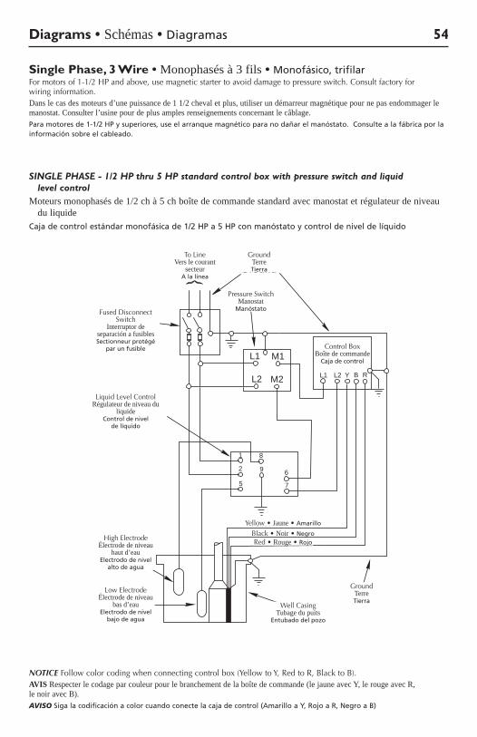
Diagrams • Schémas • Diagramas 54
SINGLE PHASE - 1/2 HP thru 5 HP standard control box with pressure switch and liquid level control
Moteurs monophasés de 1/2 ch à 5 ch boîte de commande standard avec manostat et régulateur de niveau du liquide
Caja de control estándar monofásica de 1/2 HP a 5 HP con manóstato y control de nivel de líquido
Single Phase, 3 Wire • Monophasés à 3 fils • Monofásico, trifilarFormotorsof1-1/2HPandabove,usemagneticstartertoavoiddamagetopressureswitch.Consultfactoryforwiring information.Dans le cas des moteurs d’une puissance de 1 1/2 cheval et plus, utiliser un démarreur magnétique pour ne pas endommager le manostat. Consulter l’usine pour de plus amples renseignements concernant le câblage.Para motores de 1-1/2 HP y superiores, use el arranque magnético para no dañar el manóstato. Consulte a la fábrica por la información sobre el cableado.
NOTICE Follow color coding when connecting control box (Yellow to Y, Red to R, Black to B).AVIS Respecter le codage par couleur pour le branchement de la boîte de commande (le jaune avec Y, le rouge avec R, le noir avec B).AVISO Siga la codificación a color cuando conecte la caja de control (Amarillo a Y, Rojo a R, Negro a B)
Red
YellowBlack
WellCasing
Ground
ControlBox
L1 L2 Y B R
FusedDisconnect
Switch
To Line Ground
1
2
5
8
9 6
7
HighElectrode
LowElectrode
BW LiquidLevel Control
L1 M1
L2 M2
PressureSwitch
1271 0994
To Line Vers le courant
secteur A la línea
Ground Terre Tierra
Fused Disconnect Switch
Interruptor de separación a fusibles Sectionneur protégé
par un fusible Control Box Boîte de commande
Caja de control
High Electrode Électrode de niveau
haut d’eau Electrodo de nivel
alto de agua
Low Electrode Électrode de niveau
bas d’eau Electrodo de nivel
bajo de agua
LiquidLevelControl Régulateur de niveau du
liquide Control de nivel
de líquido
Pressure Switch Manostat
Manóstato
Yellow•Jaune•Amarillo
Red•Rouge•RojoBlack•Noir•Negro
Ground Terre Tierra
Well Casing Tubage du puits
Entubado del pozo
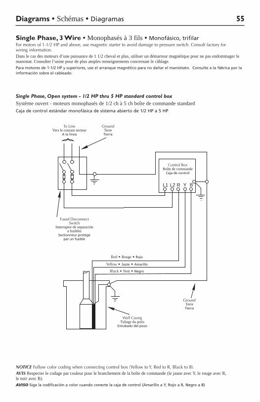
Diagrams • Schémas • Diagramas 55
Single Phase, Open system - 1/2 HP thru 5 HP standard control boxSystème ouvert - moteurs monophasés de 1/2 ch à 5 ch boîte de commande standardCaja de control estándar monofásica de sistema abierto de 1/2 HP a 5 HP
Single Phase, 3 Wire • Monophasés à 3 fils • Monofásico, trifilarFormotorsof1-1/2HPandabove,usemagneticstartertoavoiddamagetopressureswitch.Consultfactoryforwiring information.Dans le cas des moteurs d’une puissance de 1 1/2 cheval et plus, utiliser un démarreur magnétique pour ne pas endommager le manostat. Consulter l’usine pour de plus amples renseignements concernant le câblage.Para motores de 1-1/2 HP y superiores, use el arranque magnético para no dañar el manóstato. Consulte a la fábrica por la información sobre el cableado.
ControlBox
L1 L2 R Y B
FusedDisconnect
Switch
To Line Ground
RedYellowBlack
WellCasing
Ground
357 0893
To Line Vers le courant secteur
A la línea
Ground Terre Tierra
Fused Disconnect Switch
Interruptor de separación a fusibles
Sectionneur protégé par un fusible
Control Box Boîte de commande
Caja de control
Yellow•Jaune•Amarillo
Red•Rouge•Rojo
Black•Noir•Negro
Ground Terre Tierra
Well Casing Tubage du puits
Entubado del pozo
NOTICE Follow color coding when connecting control box (Yellow to Y, Red to R, Black to B).AVIS Respecter le codage par couleur pour le branchement de la boîte de commande (le jaune avec Y, le rouge avec R, le noir avec B).AVISO Siga la codificación a color cuando conecte la caja de control (Amarillo a Y, Rojo a R, Negro a B)
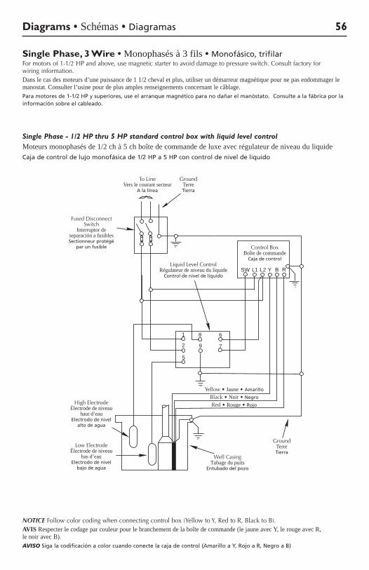
Diagrams • Schémas • Diagramas 56
Single Phase - 1/2 HP thru 5 HP standard control box with liquid level controlMoteurs monophasés de 1/2 ch à 5 ch boîte de commande de luxe avec régulateur de niveau du liquideCaja de control de lujo monofásica de 1/2 HP a 5 HP con control de nivel de líquido
Single Phase, 3 Wire • Monophasés à 3 fils • Monofásico, trifilarFormotorsof1-1/2HPandabove,usemagneticstartertoavoiddamagetopressureswitch.Consultfactoryforwiring information.Dans le cas des moteurs d’une puissance de 1 1/2 cheval et plus, utiliser un démarreur magnétique pour ne pas endommager le manostat. Consulter l’usine pour de plus amples renseignements concernant le câblage.Para motores de 1-1/2 HP y superiores, use el arranque magnético para no dañar el manóstato. Consulte a la fábrica por la información sobre el cableado.
NOTICE Follow color coding when connecting control box (Yellow to Y, Red to R, Black to B).AVIS Respecter le codage par couleur pour le branchement de la boîte de commande (le jaune avec Y, le rouge avec R, le noir avec B).AVISO Siga la codificación a color cuando conecte la caja de control (Amarillo a Y, Rojo a R, Negro a B)
Red
YellowBlack
WellCasing
Ground
ControlBox
L1 L2 Y B R
FusedDisconnect
Switch
To Line Ground
1
2
5
8
9
6
7
HighElectrode
LowElectrode
SWBW Liquid
Level Control
354 0893
Yellow•Jaune•Amarillo
Red•Rouge•Rojo
Black•Noir•Negro
To Line Vers le courant secteur
A la línea
Ground Terre Tierra
Fused Disconnect Switch
Interruptor de separación a fusibles Sectionneur protégé
par un fusible Control Box Boîte de commande
Caja de control
High Electrode Électrode de niveau
haut d’eau Electrodo de nivel
alto de agua
Low Electrode Électrode de niveau
bas d’eau Electrodo de nivel
bajo de agua
LiquidLevelControl Régulateur de niveau du liquide
Control de nivel de líquido
Well Casing Tubage du puits
Entubado del pozo
Ground Terre Tierra
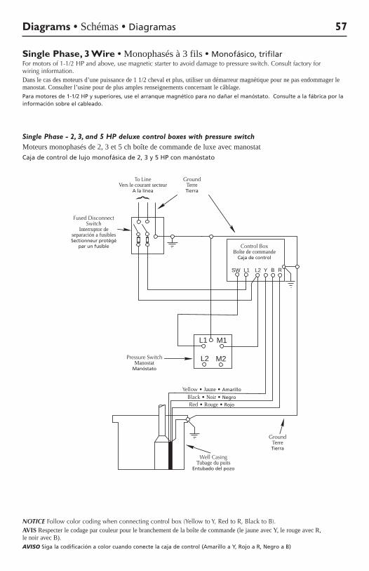
Diagrams • Schémas • Diagramas 57
Single Phase - 2, 3, and 5 HP deluxe control boxes with pressure switchMoteurs monophasés de 2, 3 et 5 ch boîte de commande de luxe avec manostatCaja de control de lujo monofásica de 2, 3 y 5 HP con manóstato
Single Phase, 3 Wire • Monophasés à 3 fils • Monofásico, trifilarFormotorsof1-1/2HPandabove,usemagneticstartertoavoiddamagetopressureswitch.Consultfactoryforwiring information.Dans le cas des moteurs d’une puissance de 1 1/2 cheval et plus, utiliser un démarreur magnétique pour ne pas endommager le manostat. Consulter l’usine pour de plus amples renseignements concernant le câblage.Para motores de 1-1/2 HP y superiores, use el arranque magnético para no dañar el manóstato. Consulte a la fábrica por la información sobre el cableado.
Red
YellowBlack
WellCasing
Ground
ControlBox
L1 L2 Y B R
FusedDisconnect
Switch
To Line Ground
SW
L1 M1
L2 M2PressureSwitch
3108 1197
To Line Vers le courant secteur
A la línea
Ground Terre Tierra
Fused Disconnect Switch
Interruptor de separación a fusibles Sectionneur protégé
par un fusible Control Box Boîte de commande
Caja de control
Pressure Switch Manostat
Manóstato
Yellow•Jaune•Amarillo
Red•Rouge•Rojo
Black•Noir•Negro
Ground Terre Tierra
Well Casing Tubage du puits
Entubado del pozo
NOTICE Follow color coding when connecting control box (Yellow to Y, Red to R, Black to B).AVIS Respecter le codage par couleur pour le branchement de la boîte de commande (le jaune avec Y, le rouge avec R, le noir avec B).AVISO Siga la codificación a color cuando conecte la caja de control (Amarillo a Y, Rojo a R, Negro a B)
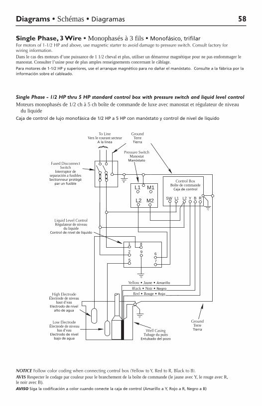
Diagrams • Schémas • Diagramas 58
Single Phase - 1/2 HP thru 5 HP standard control box with pressure switch and liquid level controlMoteurs monophasés de 1/2 ch à 5 ch boîte de commande de luxe avec manostat et régulateur de niveau
du liquideCaja de control de lujo monofásica de 1/2 HP a 5 HP con manóstato y control de nivel de líquido
Single Phase, 3 Wire • Monophasés à 3 fils • Monofásico, trifilarFormotorsof1-1/2HPandabove,usemagneticstartertoavoiddamagetopressureswitch.Consultfactoryforwiring information.Dans le cas des moteurs d’une puissance de 1 1/2 cheval et plus, utiliser un démarreur magnétique pour ne pas endommager le manostat. Consulter l’usine pour de plus amples renseignements concernant le câblage.Para motores de 1-1/2 HP y superiores, use el arranque magnético para no dañar el manóstato. Consulte a la fábrica por la información sobre el cableado.
Red
YellowBlack
WellCasing
Ground
ControlBox
L1 L2 Y B R
FusedDisconnect
Switch
To Line Ground
1
2
5
8
9 6
7
HighElectrode
LowElectrode
SW
BW LiquidLevel Control
L1 M1
L2 M2
PressureSwitch
358 0893
To Line Vers le courant secteur
A la línea
Ground Terre Tierra
Fused Disconnect Switch
Interruptor de separación a fusibles Sectionneur protégé
par un fusibleControl Box
Boîte de commande Caja de control
High Electrode Électrode de niveau
haut d’eau Electrodo de nivel
alto de agua
Low Electrode Électrode de niveau
bas d’eau Electrodo de nivel
bajo de agua
LiquidLevelControl Régulateur de niveau
du liquide Control de nivel de líquido
Pressure Switch Manostat
Manóstato
Yellow•Jaune•Amarillo
Red•Rouge•Rojo
Black•Noir•Negro
Ground Terre TierraWell Casing
Tubage du puits Entubado del pozo
NOTICE Follow color coding when connecting control box (Yellow to Y, Red to R, Black to B).AVIS Respecter le codage par couleur pour le branchement de la boîte de commande (le jaune avec Y, le rouge avec R, le noir avec B).AVISO Siga la codificación a color cuando conecte la caja de control (Amarillo a Y, Rojo a R, Negro a B)
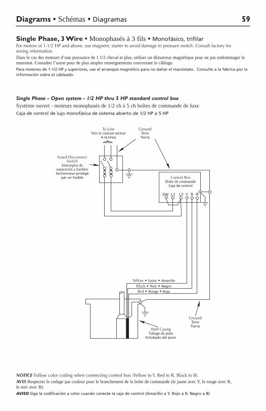
Diagrams • Schémas • Diagramas 59
Single Phase - Open system - 1/2 HP thru 5 HP standard control boxSystème ouvert - moteurs monophasés de 1/2 ch à 5 ch boîtes de commande de luxeCaja de control de lujo monofásica de sistema abierto de 1/2 HP a 5 HP
Single Phase, 3 Wire • Monophasés à 3 fils • Monofásico, trifilarFormotorsof1-1/2HPandabove,usemagneticstartertoavoiddamagetopressureswitch.Consultfactoryforwiring information.Dans le cas des moteurs d’une puissance de 1 1/2 cheval et plus, utiliser un démarreur magnétique pour ne pas endommager le manostat. Consulter l’usine pour de plus amples renseignements concernant le câblage.Para motores de 1-1/2 HP y superiores, use el arranque magnético para no dañar el manóstato. Consulte a la fábrica por la información sobre el cableado.
Red
YellowBlack
WellCasing
Ground
ControlBox
L1 L2 Y B R
FusedDisconnect
Switch
To Line Ground
SW
1270 0994
To Line Vers le courant secteur
A la línea
Ground Terre Tierra
Fused Disconnect Switch
Interruptor de separación a fusibles Sectionneur protégé
par un fusible Control Box Boîte de commande
Caja de control
Yellow•Jaune•Amarillo
Red•Rouge•Rojo
Black•Noir•Negro
Ground Terre Tierra
Well Casing Tubage du puits
Entubado del pozo
NOTICE Follow color coding when connecting control box (Yellow to Y, Red to R, Black to B).AVIS Respecter le codage par couleur pour le branchement de la boîte de commande (le jaune avec Y, le rouge avec R, le noir avec B).AVISO Siga la codificación a color cuando conecte la caja de control (Amarillo a Y, Rojo a R, Negro a B)
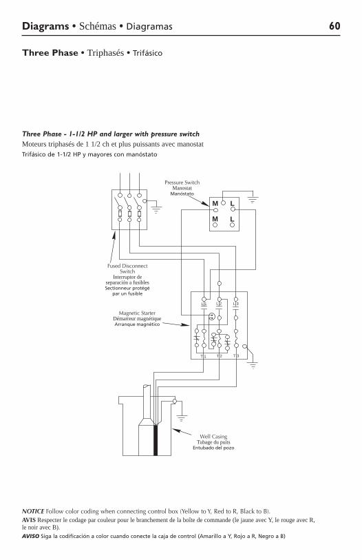
Diagrams • Schémas • Diagramas 60
Three Phase • Triphasés • Trifásico
Three Phase - 1-1/2 HP and larger with pressure switchMoteurs triphasés de 1 1/2 ch et plus puissants avec manostatTrifásico de 1-1/2 HP y mayores con manóstato
FusedDisconnectSwitch
WellCasing
LM
M L
MagneticStarter
PressureSwitch
L 1 L 2 L 3
T 1 T 2 T 3
362 0893
Pressure Switch Manostat
Manóstato
Fused Disconnect Switch
Interruptor de separación a fusibles Sectionneur protégé
par un fusible
MagneticStarter Démarreur magnétique Arranque magnético
Well Casing Tubage du puits
Entubado del pozo
NOTICE Follow color coding when connecting control box (Yellow to Y, Red to R, Black to B).AVIS Respecter le codage par couleur pour le branchement de la boîte de commande (le jaune avec Y, le rouge avec R, le noir avec B).AVISO Siga la codificación a color cuando conecte la caja de control (Amarillo a Y, Rojo a R, Negro a B)
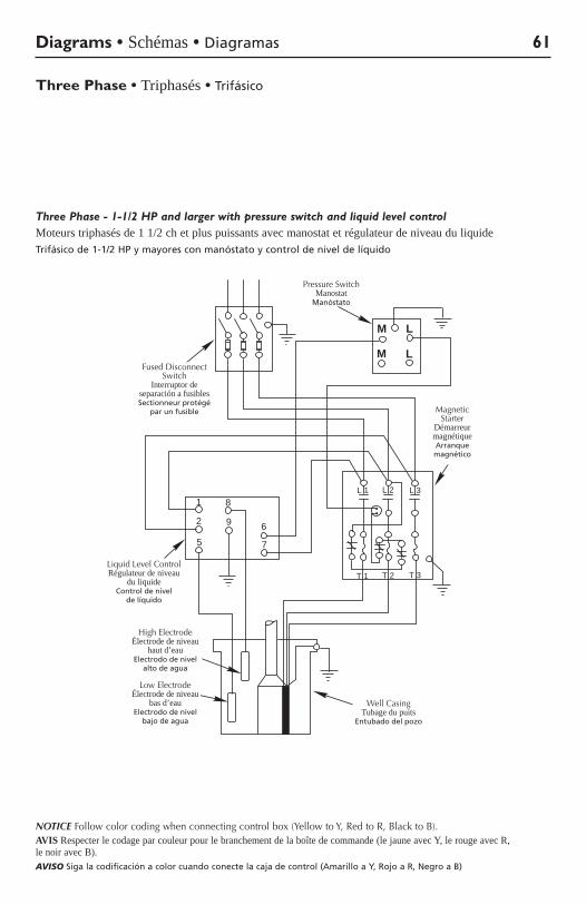
Diagrams • Schémas • Diagramas 61
Three Phase - 1-1/2 HP and larger with pressure switch and liquid level controlMoteurs triphasés de 1 1/2 ch et plus puissants avec manostat et régulateur de niveau du liquideTrifásico de 1-1/2 HP y mayores con manóstato y control de nivel de líquido
Three Phase • Triphasés • Trifásico
FusedDisconnect
Switch
WellCasing
LM
M L
MagneticStarter
PressureSwitch
1
2
5
8
9 6
7
L 1 L 2 L 3
T 1 T 2 T 3LiquidLevelControl
High Electrode
LowElectrode
361 0893
Pressure Switch Manostat
Manóstato
Fused Disconnect Switch
Interruptor de separación a fusibles Sectionneur protégé
par un fusible MagneticStarter
Démarreur magnétique Arranque magnético
High Electrode Électrode de niveau
haut d’eau Electrodo de nivel
alto de agua
Low Electrode Électrode de niveau
bas d’eau Electrodo de nivel
bajo de agua
LiquidLevelControl Régulateur de niveau
du liquide Control de nivel
de líquido
Well Casing Tubage du puits
Entubado del pozo
NOTICE Follow color coding when connecting control box (Yellow to Y, Red to R, Black to B).AVIS Respecter le codage par couleur pour le branchement de la boîte de commande (le jaune avec Y, le rouge avec R, le noir avec B).AVISO Siga la codificación a color cuando conecte la caja de control (Amarillo a Y, Rojo a R, Negro a B)
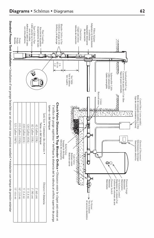
Diagrams • Schémas • Diagramas 62
Standard Pressure Tank Installation • Installation d’une pompe branchée sur un réservoir sous pression standard • Instalación con tanque de presión estándar
Ch
eck Valve D
istance To
Top
Bleed
er Orifice • D
istance entre le clapet anti-retour et l’orifice de purge supérieur • V
erifiqu
e la distan
cia del la válvu
la al orificio
sup
erior d
e pu
rga
tama—
o d
el tanq
ue
TankSize•Contenance des réservoirs• Tam
a—o
del tan
qu
eDistance•D
istancia
42Gallon(159L)
2’(60cm)
82Gallon(310L)
3’(90cm)
120Gallon(454L)
5’(1.4m)
220Gallon(833L)
5’(1.4m)
315Gallon(1192L)
10’(3.0m)
525Gallon(1987L)
15’(4.6m)
PITLESSA
DA
PTOR
CH
ECK
VA
LVE
BLEED
ER
OR
IFICE
& TEE
PIPEC
OU
PLING
TAPE C
AB
LETO
PIPEPUM
P
VEN
TILATED
WELL C
AP
SUB
MER
SIBLE
CA
BLE
UN
ION
CO
NTR
OL B
OX
(3 WIR
E MO
DELS)
ELECTR
ICA
L DISC
ON
NEC
TPRESSU
RE G
AU
GE
AIR
VO
LUM
E CO
NTR
OL
PRESSU
RE SW
ITCH
TO H
OU
SE SERV
ICE
GA
TE VA
LVE
RELIEF V
ALV
E
2 ft.(.6m
)
SEE TAB
LESee Table
Voir le tableau V
er cuad
ro
2 ft. 60cm
2 pi
BleederOrifice&
Tee O
rifices de purge et tés O
rificio y te d
e pu
rga
AirVolum
eControl
Régulateur de volume d’air
Co
ntro
l del vo
lum
en d
e aire
Pipe Coupling
Raccord de tuyauterie A
cop
lamien
to d
e tub
o
VentilatedWellC
ap Couvercle de puits m
is à l’air libre Tap
a de p
ozo
ventilad
o
Submersible C
able Câble subm
ersible C
able su
merg
ible
Union
Raccord union
ReliefValve Soupape de décharge
Válvu
la de co
mp
uerta
GateValve
Robinet-vanne R
ob
inet-van
ne
Control Box (3-w
ire models)
Boîte de comm
ande (modèles à 3 fils)
Caja d
e con
trol (m
od
elos trifilares)
Electrical Disconnect
Sélectionneur électrique D
escon
exión
eléctrica
Pressure Switch
Manostat
Man
óstato
PressureGauge
Manom
ètre M
anó
metro
To House
Vers la maison
Al servicio
do
méstico
Pump
Pompe
Bo
mb
a
Tape Cable to Pipe
Câble attaché sur le tuyau avec du ruban
Ad
hiera el cab
le al tub
o
con
cinta ad
hesiva
CheckValve
Clapet anti-retour V
álvula d
e retenció
n
Pitless Adapter
Adaptateur de branchem
ent à coulisseau
Ad
aptad
or d
eslizante
de d
erivación
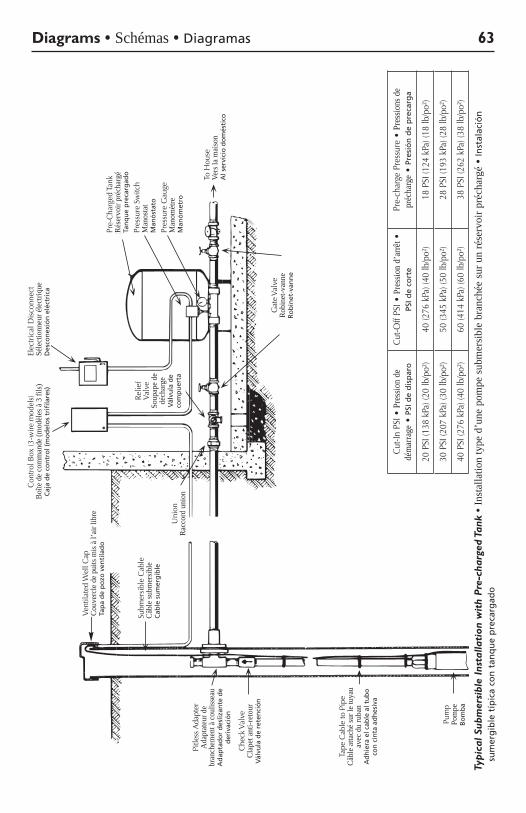
Diagrams • Schémas • Diagramas 63
Typ
ical
Sub
mer
sibl
e In
stal
lati
on w
ith
Pre
-cha
rged
Tan
k •
Inst
alla
tion
type
d’u
ne p
ompe
sub
mer
sibl
e br
anch
ée s
ur u
n ré
serv
oir p
réch
argé
• In
stal
ació
n
sum
erg
ible
típ
ica
con
tan
qu
e p
reca
rgad
o
Cut-In
PSI•
Pre
ssio
n de
dé
mar
rage• P
SI d
e d
isp
aro
Cut-O
ffPS
I•P
ress
ion
d’ar
rêt •
PS
I de
cort
ePre-ch
argePressure•
Pres
sions
de
préc
harg
e•
Pres
ión
de
pre
carg
a
20PSI(1
38kPa)(20
lb/po²)
40(2
76kPa)(40
lb/po²)
18PSI(1
24kPa)(18
lb/po²)
30PSI(2
07kPa)(30
lb/po²)
50(3
45kPa)(50
lb/po²)
28PSI(1
93kPa)(28
lb/po²)
40PSI(2
76kPa)(40
lb/po²)
60(4
14kPa)(60
lb/po²)
38PSI(2
62kPa)(38
lb/po²)
VEN
TILA
TED
WEL
L C
AP
SUB
MER
SIB
LEC
AB
LE
PITL
ESS
AD
APT
OR
CH
ECK
VA
LVE
TAPE
CA
BLE
TO P
IPE
PUM
P
CO
NTR
OL
BO
X(3
WIR
E M
OD
ELS)
ELEC
TRIC
AL
DIS
CO
NN
ECT PR
E-C
HA
RG
ED T
AN
K
PRES
SUR
E SW
ITC
H
PRES
SUR
E G
AU
GE
TO H
OU
SE S
ERV
ICE
REL
IEF
VA
LVE
UN
ION
GA
TE V
ALV
E
Ventila
tedWellC
ap
Couv
ercl
e de
pui
ts m
is à
l’air
libre
Ta
pa
de
po
zo v
enti
lad
o
Subm
ersi
ble
Cab
le
Câbl
e su
bmer
sible
C
able
su
mer
gib
le
Union
Ra
ccor
d un
ion
Relie
f Va
lve
Soup
ape
de
déch
arge
V
álvu
la d
e co
mp
uer
ta
GateVa
lve
Robi
net-v
anne
R
ob
inet
-van
ne
Con
trol B
ox (3
-wire
mod
els)
Bo
îte d
e co
mm
ande
(mod
èles
à 3
fils)
C
aja
de
con
tro
l (m
od
elo
s tr
ifila
res)
Elec
trica
l Dis
conn
ect
Séle
ctio
nneu
r éle
ctriq
ue
Des
con
exió
n e
léct
rica
Pres
sure
Sw
itch
Man
osta
t M
anó
stat
o
Pre-
Cha
rged
Tan
k Ré
serv
oir p
réch
argé
Ta
nq
ue
pre
carg
ado
PressureG
auge
M
anom
ètre
M
anó
met
ro
To H
ouse
Ve
rs la
mai
son
Al s
ervi
cio
do
més
tico
Pum
p Po
mpe
B
om
ba
Tape
Cab
le to
Pip
e Câ
ble
atta
ché
sur l
e tu
yau
avec
du
ruba
n A
dh
iera
el c
able
al t
ub
o
con
cin
ta a
dh
esiv
a
Che
ckValve
Cl
apet
ant
i-ret
our
Vál
vula
de
rete
nci
ón
Pitle
ss A
dapt
er
Ada
ptat
eur d
e br
anch
emen
t à c
oulis
seau
A
dap
tad
or
des
lizan
te d
e d
eriv
ació
n