Embed Size (px)
Citation preview
U.Porto Journal of Engineering, 2:3 (2016) 53-65
ISSN 2183-6493
DOI 10.24840/2183-6493_002.003_0006
Received: 28 October, 2015
Accepted: 8 December, 2016
Published: 13 January, 2017
53
Grillage modeling approach applied to simple-span slab-
girder skewed bridges for dynamic analysis
Miriam Guadalupe López Chávez1, António Arêde2, José Manuel Jara
Guerrero3, Pedro Delgado4, Humberto Varum5 1,2,5Department of Civil Engineering, Faculty of Engineering, University of Porto, Porto,
Portugal; 3Faculty of Civil Engineering, University of Michoacan, Michoacan, Mexico; 4Polytechnic Institute of Viana do Castelo, Viana do Castelo, Portugal
([email protected], [email protected], [email protected], [email protected], [email protected])
Abstract
This study involves the applicability of a simplified modeling technique to simple-
span slab-girder skewed bridges for dynamic analysis, based on grillage modeling
strategies. To evaluate the applicability of this technique, skew angles ranging from
0° to 60° are studied. The ability to capture vibration modes of grillage models is
compared with three-dimensional (3-D) finite element (FE) models, using shell and
frame elements. The effect of the skew angle in the grillage modeling technique of
the bridge's deck and the grillage model accuracy associated with the orientation of
the transverse grillage members (TGMs) are studied. The grillage modeling
technique eliminates shell elements to model the slab, reducing the number of
degrees of freedom and the computational time in the bridge model, but, although
its simplicity, demonstrates good ability to capture the vibration modes.
Subject Headings. Bridge, Civil Engineering
Author Keywords. Skewed Bridges, Modeling Technique, Grillage Analogy, Modal
Analysis
1. Introduction
In order to maintain the geometry and the straight alignment in a road design, bridges with
skew-angled supports (a.k.a. 'skewed bridges') have been used frequently for planning and
design of highways, and their number has increased all over the world in the last years.
However, skewed bridges are more vulnerable to severe earthquake-induced damage than
straight bridges with regular geometry (Jennings et al. 1971). Skewed bridges are
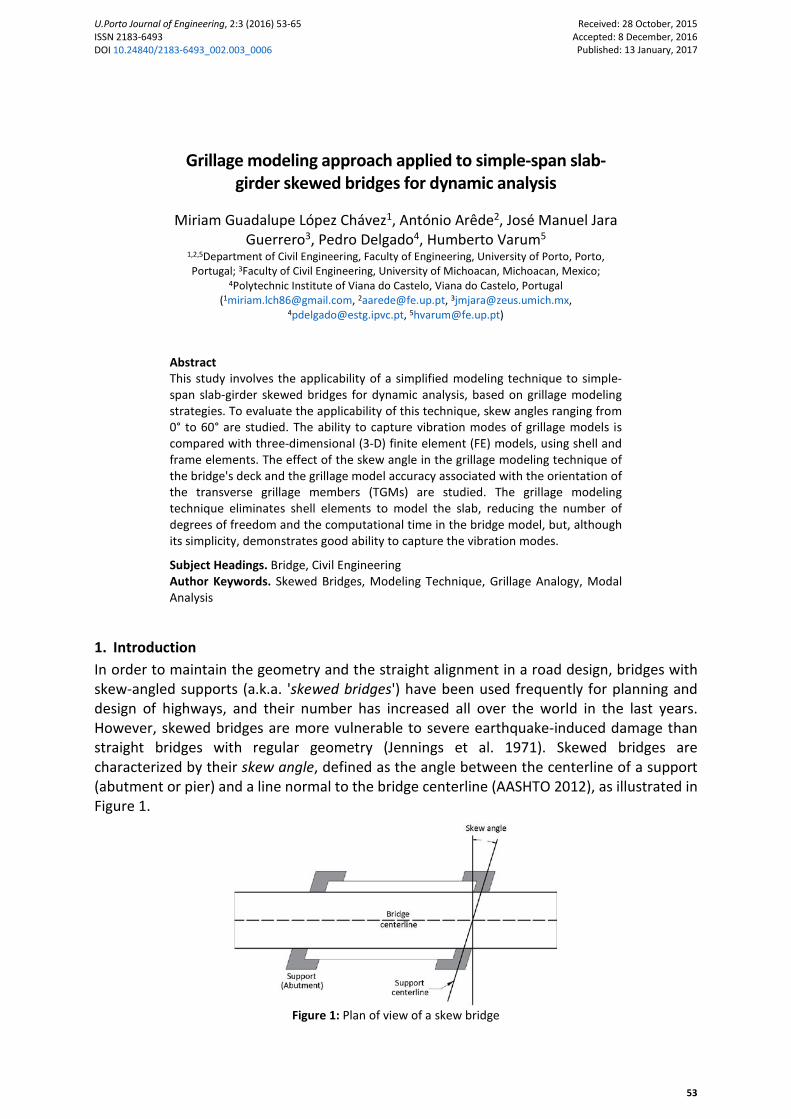
characterized by their skew angle, defined as the angle between the centerline of a support
(abutment or pier) and a line normal to the bridge centerline (AASHTO 2012), as illustrated in
Figure 1.
Figure 1: Plan of view of a skew bridge
Grillage modeling approach applied to simple-span slab-girder skewed bridges for dynamic analysis
Miriam Guadalupe López Chávez, António Arêde, José Manuel Jara Guerrero, Pedro Delgado, Humberto Varum
U.Porto Journal of Engineering, 2:3 (2016) 53-65 54
Scientific research after major earthquakes has contributed to improve the understanding of
seismic performance of bridges, and to modify existing design guidelines and analysis
procedures. Simultaneously, a large number of studies on the modeling and seismic response
of skewed bridges have been carried out (e.g. Abdel-Mohti and Pekcan 2013, Bjornsoon,
Stanton, and Eberhard 1998, Ghobarah and Tso 1974, Kaviani, Zareian, and Taciroglu 2014,
Maleki 2001, Maragakis and Jennings 1987, Meng, Lui, and Liu 2001, Saiidi and Orie 1992,
Wakefield, Nazmy, and Billington 1991). Notwithstanding this progress, the inherent and
complex behavior of skewed bridges subjected to seismic loads is not completely clarified. As
a result, the seismic vulnerability of this type of bridges remains uncertain.
The assumptions in the analytical modelling of skewed bridges have a direct effect on the
results. The underlying assumptions relate to material modeling, response characteristics of
the components, boundary conditions, soil-structure interaction, component modeling [i.e.
beam-stick (BS) & finite element (FE)], superstructure, seismic mass, etc. (Abdel-Mohti and
Pekcan 2013, Haque and Bhuiyan 2012). This paper discusses typical modeling techniques
used for skewed bridges, which is the first step in the development of a bridge model.
Over the years, different modeling techniques have been developed by researchers to analyze
bridges under seismic loads. A bridge superstructure can be modeled in a variety of ways,
most of them focused in the superstructure idealization, ranging from the very simple BS
model to the rather sophisticated FE model. However, some modeling techniques of bridges
available in the literature introduce geometric and compatibility errors, which can affect their
ability to capture the actual seismic behavior of the structure. Furthermore, an irregular
geometry, as in the case of skewed bridges, can increase the model errors.
A suitable modeling technique should be capable of capturing the vibration modes of the
bridge subjected to seismic excitation (Meng and Lui 2002). Since the free vibration of skewed
bridges is greatly affected by the skew angle, the modeling technique selected must take into
consideration the effect of this parameter. Higher modes such as twisting and coupled
flexural-torsional are important in assessing the seismic response of skewed bridges.
Neglecting higher modes can introduce significant errors in the results of dynamic analysis
(Aviram, Mackie, and Stojadinovic 2008).
Since BS models are incapable to properly capture twisting and coupled flexural-torsional
vibrations, some researches propose the use of refined models for dynamic analysis of skewed
bridges. The improved BS models proposed by Meng and Lui (2002) and Abdel-Mohti and
Pekcan (2013), conduct to conclude that the increase of the number of lines of frame elements
in BS models, produces more accurate results.
Alternatively to BS models, accurate results can be expected when idealizing a bridge
superstructure as a grillage (Memory, Thambiratnam, and Brameld 1995). In the grillage
modeling approach applied to slab-girder bridges, an equivalent grillage represents the three
primary components of this type of bridges, namely: (1) the longitudinal girders, (2) the
transverse end and intermediate diaphragms, and (3) the slab. Frame elements model the
superstructure in both directions, eliminating the shell elements representing the slab.
This study analyzes the applicability of a simplified technique to model slab-girder skewed
bridges, based on grillage modeling strategies. The ability of models, constructed with a
grillage modeling approach (hereinafter referred to as 'grillage models') to accurately capture
vibration modes is compared with three-dimensional (3-D) FE models, using shell and frame
elements. Due to the inherent behavior of skewed bridges, this paper discusses the influence
of skew angle in the grillage modeling technique of the bridge's deck.
Grillage modeling approach applied to simple-span slab-girder skewed bridges for dynamic analysis
Miriam Guadalupe López Chávez, António Arêde, José Manuel Jara Guerrero, Pedro Delgado, Humberto Varum
U.Porto Journal of Engineering, 2:3 (2016) 53-65 55
2. Description of the Study
To evaluate the applicability of grillage modeling approach to simple-span slab-girder skewed
bridges, the response of bridge models with skew angle ranging from 0° to 60° is studied. The
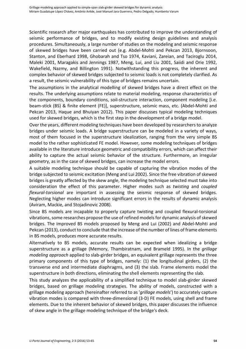
bridges have a span length of L = 20 m, with a superstructure width of W = 10.60 m. The
superstructure is composed by six Type-IV AASTHO prestressed concrete (PC) girders (equally
spaced at 1.80m on-center), behaving compositely with a 0.20m thick reinforced concrete (RC)
slab. Figure 2 shows the transverse cross-section of the superstructure. The bridges have RC
end diaphragms and an intermediate diaphragm, aligned along the skew angle. These
transverse members provide stability of longitudinal girders and distribute vertical and lateral
loads, while providing restraint for lateral-torsional buckling of the girders (Maleki and Hojat
Jalali 2012).
Figure 2: Transverse cross-section of the superstructure
Two types of support conditions are considered in the models, namely: (a) girders supported
on pinned bearings, and (b) girders supported on elastomeric bearings, whose size is
0.30 x 0.30 x 0.057m (width x length x height). There is an expansion joint at both ends of the
bridges and the abutment stiffness was not explicitly included in the models.
The compressive strength of the RC bridge members is f'c = 25MPa, and f'c = 35MPa for the PC
bridge members. The elastic modulus of concrete, Ec, depends on the concrete compressive
strength [Ec = 4 400√(f'c)], then Ec of the RC bridge members is EcR = 22’000MPa, and EcP =
26’030MPa for the PC bridge members. The modular ratio, m, between RC and PC is given by
m = EcR/EcP. Thus, the modular ratio for the RC slab and PC girders is m = 0.8452. The yield
strength of the reinforcing bars is Fy = 411.90MPa.
The dynamic behavior of the RC simple-span bridges is studied with 3-D FE models and grillage
models, both considering flexible deck. The analytical models for the bridges were developed
with SAP2000 software (CSI 2015).
2.1. Finite Element (FE) Models
The simplest 3-D FE model represents the superstructure components using shell and beam
elements. Special consideration is required on the interface of the slab and the beams to
account for the beam's center of gravity position (Mabsout et al. 1997, Meng and Lui 2000,
Zahrai and Bruneau 1998).
RC slabs in the 3-D FE models were modeled with quadrilateral shell elements, using a mesh
of 1.67 x 1.80m, whereas girders and diaphragms were modeled with frame elements. Small
discrete segments divide frame elements with mass assigned equally at each node, and same
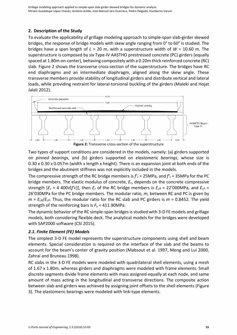
amount of mass acting in the longitudinal and transverse directions. The composite action
between slab and girders was achieved by assigning joint offsets to the shell elements (Figure
3). The elastomeric bearings were modeled with link-type elements.
Grillage modeling approach applied to simple-span slab-girder skewed bridges for dynamic analysis
Miriam Guadalupe López Chávez, António Arêde, José Manuel Jara Guerrero, Pedro Delgado, Humberto Varum
U.Porto Journal of Engineering, 2:3 (2016) 53-65 56
Figure 3: Slab and girders composite action
2.2. Grillage Models
There are two important steps in grillage modeling approach: (i) to simulate the bridge
structure into equivalent grillage mesh, and (ii) to assign appropriate elastic properties to each
member of the grillage. For the first step and given the great variety of bridge typologies, there
are not specific guidelines to choose a grillage mesh for a skewed bridge. A suitable grillage
mesh for skewed bridges depends on the skew angle, the span length, and the deck width. In
this study, we considered the general recommendations suggested in the literature (Hambly
1991, OBrien, Keogh, and O'Connor 2015, Surana and Agrawal 1998).
The second step of the grillage modeling approach is to assign appropriate properties to the
grillage members to obtain similitude between the grillage model and the corresponding
bridge slab. To achieve similitude of bending moments between the slab and the
corresponding grillage, it is necessary to adopt the same elastic modulus, Ec, and second
moment of area, I, per unit breadth in the grillage as that of the slab. To achieve similitude of
twisting moments in the slab and torques in the grillage members, it is necessary to adopt the
same shear modulus, Gc, and torsion constant, T, in the grillage member as in the slab.
2.2.1. Longitudinal Grillage Members (LGMs) – Geometric Definition and Properties
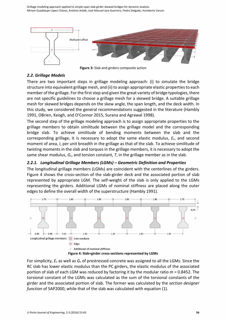
The longitudinal grillage members (LGMs) are coincident with the centerlines of the girders.
Figure 4 shows the cross-section of the slab-girder deck and the associated portion of slab
represented by appropriate LGM. The self-weight of the slab is only applied to the LGMs
representing the girders. Additional LGMs of nominal stiffness are placed along the outer
edges to define the overall width of the superstructure (Hambly 1991).
Figure 4: Slab+girder cross-sections represented by LGMs
For simplicity, Ec as well as Gc of prestressed concrete was assigned to all the LGMs. Since the
RC slab has lower elastic modulus than the PC girders, the elastic modulus of the associated
portion of slab of each LGM was reduced by factoring it by the modular ratio m = 0.8452. The
torsional constant of the LGMs was calculated as the sum of the torsional constants of the
girder and the associated portion of slab. The former was calculated by the section designer
function of SAP2000, while that of the slab was calculated with equation (1).

Grillage modeling approach applied to simple-span slab-girder skewed bridges for dynamic analysis
Miriam Guadalupe López Chávez, António Arêde, José Manuel Jara Guerrero, Pedro Delgado, Humberto Varum
U.Porto Journal of Engineering, 2:3 (2016) 53-65 57
T = (bd3)/6 (1)
where b is the slab width represented by the LGM, while d is the slab thickness.
2.2.2. Transverse Grillage Members (TGMs) – Geometric Definition and Properties
According to OBrien, Keogh, and O'Connor (2015), the recommended spacing of transverse
grillage members (TGMs) should be similar to that of LGMs. Since the spacing between LGMs
is 1.80 m, the effective span length was divided into 12 parts. Thus, the resulting spacing of
TGMs is 1.67 m. The I and T properties of the TGMs representing the slab are calculated with
equation (2) and equation (1), respectively. In this case, b is the slab width represented by the
TGM.
I = (bd3)/12 (2)
The TGMs should generally be oriented perpendicular to the LGMs unless the transverse
reinforcement is in the skew direction. To assess the grillage model accuracy of the TGMs,
bridge models with two different TGM orientations were developed, as shown in Figure 5: (a)
TGMs in the skew direction, and (b) TGMs perpendicular to the LGMs.
(a)
(b)
–– end diaphragms –– intermediate diaphragms
Figure 5: TGM orientation: (a) TGMs in the skew direction,
and (b) TGMs perpendicular to the LGMs
RC end diaphragms and an intermediate diaphragm represented by TGMs are considered in
the bridge models. As the diaphragms are aligned along the skew angle, their properties were
only modified when the TGMs, representing the slab, were oriented in the skew direction
(Figure 5a). In this case, the second moment of area of each TGMs was calculated about the
centroid of the section it represents. In addition, the torsional constant is calculated as the
sum of the torsional constants of the diaphragm and the associated portion of slab. Ec and Gc
of reinforced concrete were assigned to all the TGMs.
3. Modal Analysis
3.1. Terminology
To compare the natural vibration frequencies, the mode shapes, and mass participation
factors of the first 12 modes, modal analyses were conducted. The following nomenclature,
uvwwxxy-zz, identifies the bridge models:
u model type: "S" = 3-D FE Spatial model, or "G" = Grillage model;
v model name: "T" if the grillage model has TGMs perpendicular to the LGMs (or
if the 3-D FE model has right-angled shell elements);
ww skew angle: "00", "15", "30", "45", or "60";
xx model name: "ID" if the bridge model has an Intermediate Diaphragm;
y type of supports: "a" = pinned bearings, or "b" = elastomeric bearings, and
Grillage modeling approach applied to simple-span slab-girder skewed bridges for dynamic analysis
Miriam Guadalupe López Chávez, António Arêde, José Manuel Jara Guerrero, Pedro Delgado, Humberto Varum
U.Porto Journal of Engineering, 2:3 (2016) 53-65 58
zz number of elements to divide the girder; in the study the girders were divided
into 12 elements.
3.2. Natural Vibration Frequencies – 3-D FE Bridge Models
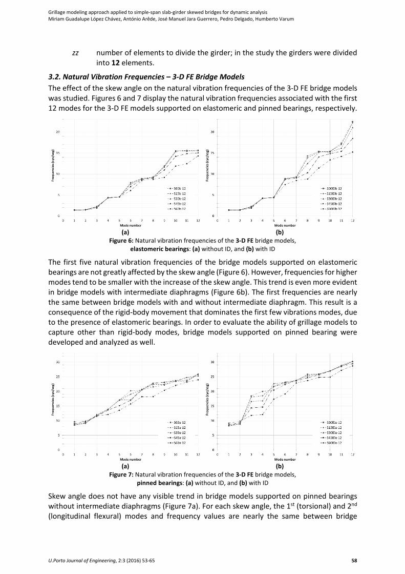
The effect of the skew angle on the natural vibration frequencies of the 3-D FE bridge models
was studied. Figures 6 and 7 display the natural vibration frequencies associated with the first
12 modes for the 3-D FE models supported on elastomeric and pinned bearings, respectively.
(a)
(b)
Figure 6: Natural vibration frequencies of the 3-D FE bridge models,
elastomeric bearings: (a) without ID, and (b) with ID
The first five natural vibration frequencies of the bridge models supported on elastomeric
bearings are not greatly affected by the skew angle (Figure 6). However, frequencies for higher
modes tend to be smaller with the increase of the skew angle. This trend is even more evident
in bridge models with intermediate diaphragms (Figure 6b). The first frequencies are nearly
the same between bridge models with and without intermediate diaphragm. This result is a
consequence of the rigid-body movement that dominates the first few vibrations modes, due
to the presence of elastomeric bearings. In order to evaluate the ability of grillage models to
capture other than rigid-body modes, bridge models supported on pinned bearing were
developed and analyzed as well.
(a)
(b)
Figure 7: Natural vibration frequencies of the 3-D FE bridge models,
pinned bearings: (a) without ID, and (b) with ID
Skew angle does not have any visible trend in bridge models supported on pinned bearings
without intermediate diaphragms (Figure 7a). For each skew angle, the 1st (torsional) and 2nd
(longitudinal flexural) modes and frequency values are nearly the same between bridge
Grillage modeling approach applied to simple-span slab-girder skewed bridges for dynamic analysis
Miriam Guadalupe López Chávez, António Arêde, José Manuel Jara Guerrero, Pedro Delgado, Humberto Varum
U.Porto Journal of Engineering, 2:3 (2016) 53-65 59
models, independently of the presence of intermediate diaphragms. Nonetheless, the 3rd and
4th modes of models with intermediate diaphragms are greatly affected by the skew angle
(Figure 7b).
The 3rd mode of 0° and 15° skewed bridge models is a transverse flexural mode, which is
independent of the intermediate diaphragms. However, for 30° and 45° skewed bridge
models, the 3rd mode (transverse flexural) of models without ID corresponds to the 4th mode
of models with ID. The 3rd mode of the latter models is a coupled flexural-torsional mode and
its frequency is almost the same of the 4th mode. The coupled flexural-torsional mode for the
15° skewed bridge is the 4th one. In all cases, the intermediate diaphragm increases the
frequency values of the 3rd and 4th modes. This effect tends to be smaller with the increase of
the skew angle.
The 60° skewed bridge models (with and without ID) present the highest frequency values for
the first two modes and the lowest one’s for the remaining modes. The intermediate
diaphragm does not affect the behavior of such bridge models for the first few modes,
presenting correspondence between mode shapes and frequencies of the first four modes.
3.3. Comparison of Bridge Modeling Techniques
To continue evaluating the grillage and 3-D FE models methodologies, natural vibration
frequencies, mode shapes, and modal participating mass ratios were studied. To compare
mode shapes of both models, the Modal Assurance Criterion (MAC) was used. The MAC is a
mathematical tool used to compare two vectors, providing a measure of the least-squares
deviation or scatter of the point from straight-line correlation. The MAC can be used to
determine the degree of consistency between modes shapes (Pastor, Binda, and Harčarik 2012), and it is bounded between 0 and 1; 1 indicating fully consistent mode shapes.
The MAC between two modes shape vectors �𝜑𝜑𝑔𝑔�𝑟𝑟 and {𝜑𝜑𝑠𝑠}𝑞𝑞 is defined as,
MAC ��𝜑𝜑𝑔𝑔�𝑟𝑟 , {𝜑𝜑𝑠𝑠}𝑞𝑞� =��𝜑𝜑𝑔𝑔�𝑟𝑟𝑇𝑇 {𝜑𝜑𝑠𝑠}𝑞𝑞 �2��𝜑𝜑𝑔𝑔�𝑟𝑟𝑇𝑇�𝜑𝜑𝑔𝑔�𝑟𝑟� �{𝜑𝜑𝑠𝑠}𝑞𝑞𝑇𝑇{𝜑𝜑𝑠𝑠}𝑞𝑞� (3)
where �𝜑𝜑𝑔𝑔�𝑟𝑟 and {𝜑𝜑𝑠𝑠}𝑞𝑞 are the modal vector of the grillage model for mode 𝑟𝑟 and the modal
vector of the 3-D FE model for mode 𝑞𝑞, respectively, while �𝜑𝜑𝑔𝑔�𝑟𝑟𝑇𝑇and {𝜑𝜑𝑠𝑠}𝑞𝑞𝑇𝑇 are the transpose
of the aforementioned modal vectors.
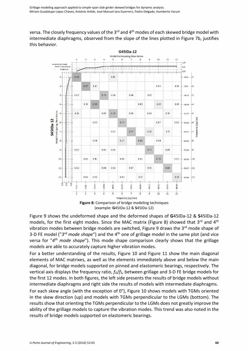
Figure 8 shows the comparison of the natural vibration frequencies, mode shapes, and modal
participating mass ratios between grillage models and 3-D FE models. The information
included in these figures is:
(i) MAC matrix (in 2-D plot) for the first 12 modes;
(ii) Cumulative sum of the square root of the squares’ sum of modal participating mass
ratios for each of the degrees of freedom (translational – solid line; rotational ---
dashed line). Grillage model and 3-D FE model plotted at the top and at the left side of
the figure, respectively. This information illustrates how many modes shall be deemed
to capture a certain level of accuracy for dynamic analysis, and
(iii) The bottom and the right side of the figure displays the computed natural vibration
frequencies for the grillage model and 3-D FE model, respectively.
Figure 8 shows the results of the 45° skewed bridge models with intermediate diaphragm
supported on pinned bearings. Some modes switch, particularly the 3rd and 4th modes. In this
case, the 3rd mode of 3-D FE model corresponds to the 4th mode of grillage model, and vice
Grillage modeling approach applied to simple-span slab-girder skewed bridges for dynamic analysis
Miriam Guadalupe López Chávez, António Arêde, José Manuel Jara Guerrero, Pedro Delgado, Humberto Varum
U.Porto Journal of Engineering, 2:3 (2016) 53-65 60
versa. The closely frequency values of the 3rd and 4th modes of each skewed bridge model with
intermediate diaphragms, observed from the slope of the lines plotted in Figure 7b, justifies
this behavior.
Figure 8: Comparison of bridge modeling techniques
(example: G45IDa-12 & S45IDa-12)
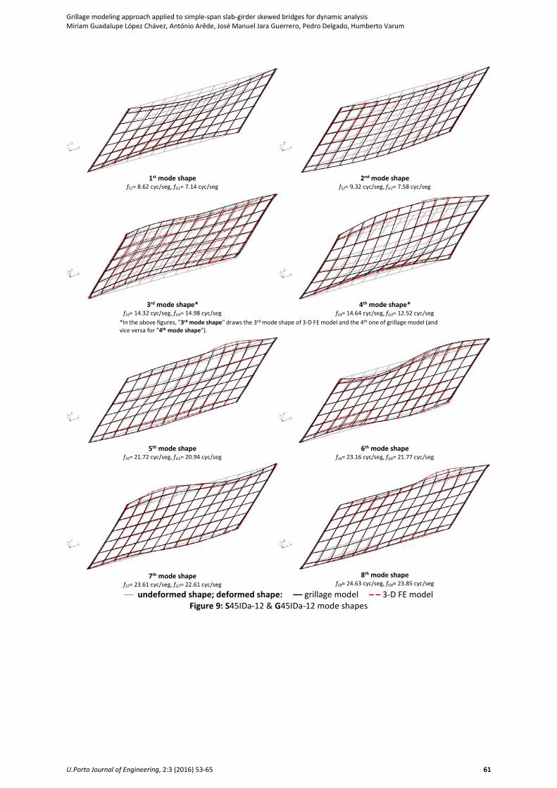
Figure 9 shows the undeformed shape and the deformed shapes of G45IDa-12 & S45IDa-12
models, for the first eight modes. Since the MAC matrix (Figure 8) showed that 3rd and 4th
vibration modes between bridge models are switched, Figure 9 draws the 3rd mode shape of
3-D FE model ("3rd mode shape") and the 4th one of grillage model in the same plot (and vice
versa for "4th mode shape"). This mode shape comparison clearly shows that the grillage
models are able to accurately capture higher vibration modes.
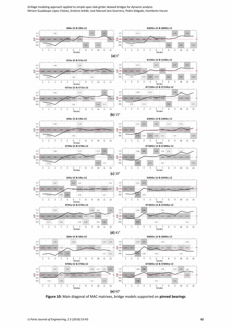
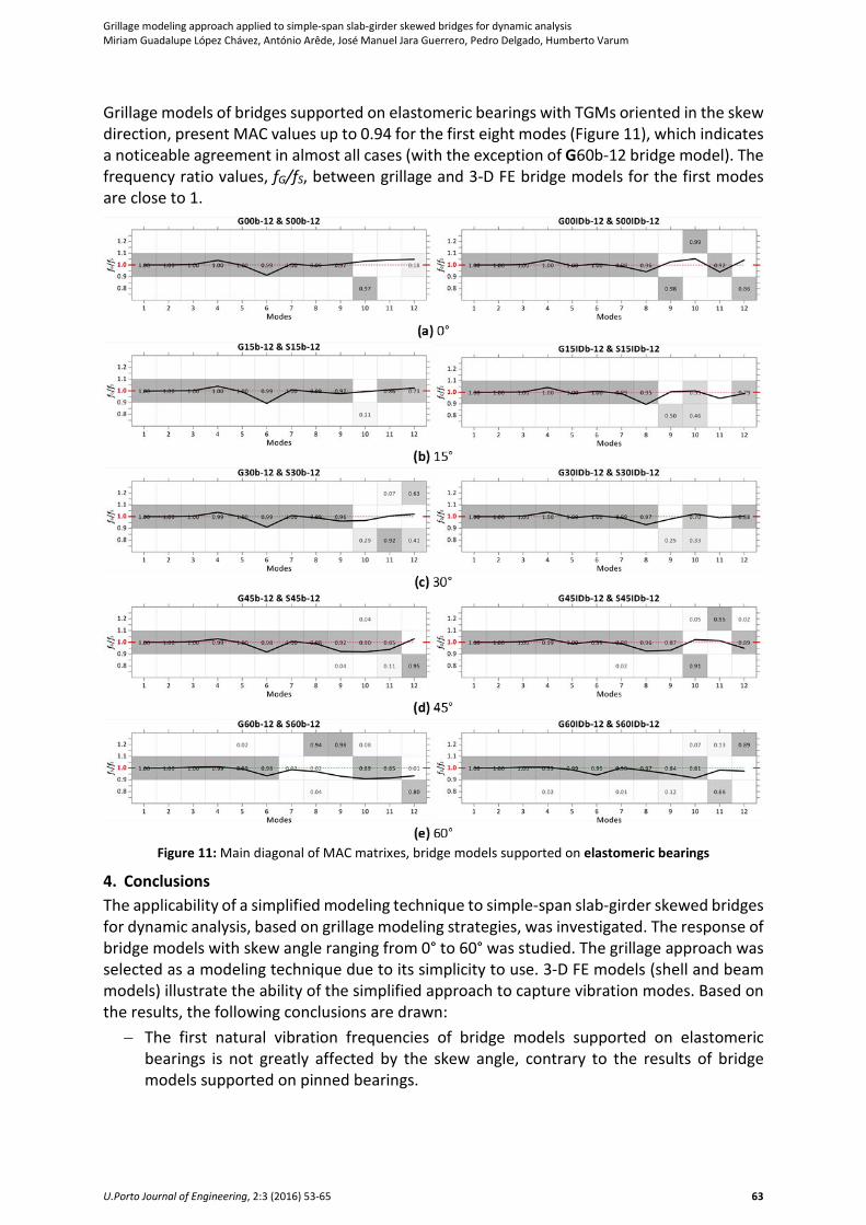
For a better understanding of the results, Figure 10 and Figure 11 show the main diagonal
elements of MAC matrixes, as well as the elements immediately above and below the main
diagonal, for bridge models supported on pinned and elastomeric bearings, respectively. The
vertical axis displays the frequency ratio, fG/fS, between grillage and 3-D FE bridge models for
the first 12 modes. In both figures, the left side presents the results of bridge models without
intermediate diaphragms and right side the results of models with intermediate diaphragms.
For each skew angle (with the exception of 0°), Figure 10 shows models with TGMs oriented
in the skew direction (up) and models with TGMs perpendicular to the LGMs (bottom). The
results show that orienting the TGMs perpendicular to the LGMs does not greatly improve the
ability of the grillage models to capture the vibration modes. This trend was also noted in the
results of bridge models supported on elastomeric bearings.
Grillage modeling approach applied to simple-span slab-girder skewed bridges for dynamic analysis
Miriam Guadalupe López Chávez, António Arêde, José Manuel Jara Guerrero, Pedro Delgado, Humberto Varum
U.Porto Journal of Engineering, 2:3 (2016) 53-65 61
1st mode shape
fS1= 8.62 cyc/seg, fG1= 7.14 cyc/seg
2nd mode shape fS2= 9.32 cyc/seg, fG2= 7.58 cyc/seg
3rd mode shape*
fS3= 14.32 cyc/seg, fG4= 14.98 cyc/seg
4th mode shape* fS4= 14.64 cyc/seg, fG3= 12.52 cyc/seg
*In the above figures, "3rd mode shape" draws the 3rd mode shape of 3-D FE model and the 4th one of grillage model (and
vice versa for "4th mode shape").
5th mode shape
fS5= 21.72 cyc/seg, fG5= 20.94 cyc/seg
6th mode shape fS6= 23.16 cyc/seg, fG6= 21.77 cyc/seg
7th mode shape
fS7= 23.61 cyc/seg, fG7= 22.61 cyc/seg
8th mode shape fS8= 24.63 cyc/seg, fG8= 23.85 cyc/seg
–– undeformed shape; deformed shape: –– grillage model – – 3-D FE model
Figure 9: S45IDa-12 & G45IDa-12 mode shapes
Grillage modeling approach applied to simple-span slab-girder skewed bridges for dynamic analysis
Miriam Guadalupe López Chávez, António Arêde, José Manuel Jara Guerrero, Pedro Delgado, Humberto Varum
U.Porto Journal of Engineering, 2:3 (2016) 53-65 62
Figure 10: Main diagonal of MAC matrixes, bridge models supported on pinned bearings
Grillage modeling approach applied to simple-span slab-girder skewed bridges for dynamic analysis
Miriam Guadalupe López Chávez, António Arêde, José Manuel Jara Guerrero, Pedro Delgado, Humberto Varum
U.Porto Journal of Engineering, 2:3 (2016) 53-65 63
Grillage models of bridges supported on elastomeric bearings with TGMs oriented in the skew
direction, present MAC values up to 0.94 for the first eight modes (Figure 11), which indicates
a noticeable agreement in almost all cases (with the exception of G60b-12 bridge model). The
frequency ratio values, fG/fS, between grillage and 3-D FE bridge models for the first modes
are close to 1.
Figure 11: Main diagonal of MAC matrixes, bridge models supported on elastomeric bearings
4. Conclusions
The applicability of a simplified modeling technique to simple-span slab-girder skewed bridges
for dynamic analysis, based on grillage modeling strategies, was investigated. The response of
bridge models with skew angle ranging from 0° to 60° was studied. The grillage approach was
selected as a modeling technique due to its simplicity to use. 3-D FE models (shell and beam
models) illustrate the ability of the simplified approach to capture vibration modes. Based on
the results, the following conclusions are drawn:
− The first natural vibration frequencies of bridge models supported on elastomeric
bearings is not greatly affected by the skew angle, contrary to the results of bridge
models supported on pinned bearings.
Grillage modeling approach applied to simple-span slab-girder skewed bridges for dynamic analysis
Miriam Guadalupe López Chávez, António Arêde, José Manuel Jara Guerrero, Pedro Delgado, Humberto Varum
U.Porto Journal of Engineering, 2:3 (2016) 53-65 64
− The intermediate diaphragm, aligned along the skew angle, introduces an additional
mode (coupled flexural-torsional mode), increasing the frequency values for the first
few modes. However, this effect tends to be smaller with the increase of the skew angle.
− The orientation of TGMs perpendicular to the LGMs does not greatly improve the ability
of the grillage models to capture the vibration modes.
− According to the comparative analysis, grillage models are able to accurately capture
higher vibration modes
− Even though a bridge superstructure is usually strong enough to remain elastic under
seismic loads, the reduction of degrees of freedom in the bridge models makes grillage
modeling approach suitable for computationally intensive studies, as those involving a
large number of nonlinear time-history analyses.
− For further validation of the modeling techniques, a comparison of the methods
performance should be carried out, in terms of nonlinear analysis.
References
AASHTO. 2012. AASHTO LRFD Bridge Design Specifications, Customary U.S. Units. 6th ed.
Washington D.C.: American Association of State Highway and Transportation Officials.
Abdel-Mohti, A., and G. Pekcan. 2013. "Assessment of seismic performance of skew reinforced
concrete box girder bridges." International Journal of Advanced Structural Engineering
(IJASE) 5 (1):1-18. DOI: 10.1186/2008-6695-5-1.
Aviram, A., K. R. Mackie, and B. Stojadinovic. 2008. Guidelines for nonlinear analysis of bridge
structures in California. Berkeley, California: Pacific Earthquake Engineering Research
Center, University of California.
Bjornsoon, S., J. Stanton, and M. Eberhard. 1998. "Seismic response of skew bridges."
Proceedings of the 6th U.S. National Conference on Earthquake Engineering, Seattle,
Washington.
SAP2000 17.3.0. Computers and Structures, Inc., Berkeley, California.
Ghobarah, A. A., and W. K. Tso. 1974. "Seismic analysis of skewed highway bridges with
intermediate supports." Earthquake Engineering & Structural Dynamics 2 (3):235-248. DOI:
10.1002/eqe.4290020304.
Hambly, E. C. 1991. Bridge deck behaviour. New York: Taylor & Francis.
Haque, M. N., and M. A. R. Bhuiyan. 2012. "Seismic response analysis of simple span concrete
deck girder skewed bridge: effect of skew angles." Journal of Civil Engineering (IEB) 40
(2):227-237.
Jennings, P. C., G. W. Housner, D. E. Hudson, M. D. Trifunac, G. A. Frazier, J. H. Wood, R. F.
Scott, W. D. Iwan, and A. G. Brady. 1971. Engineering features of the San Fernando
earthquake of February 9, 1971. Pasadena, California: California Institute of Technology.
Kaviani, P., F. Zareian, and E. Taciroglu. 2014. Performance-based seismic assessment of
skewed bridges. Berkeley, California: Pacific Earthquake Engineering Research Center,
University of California.
Mabsout, M. E., K. M. Tarhini, G. R. Frederick, and C. Tayar. 1997. "Finite-element analysis of
steel girder highway bridges." ASCE Journal of Bridge Engineering 2 (3):83-87. DOI:
10.1061/(ASCE)1084-0702(1997)2:3(83).
Maleki, S. 2001. "Free vibration of skewed bridges." Journal of Vibration and Control 7 (7):935-
952. DOI: 10.1177/107754630100700701.

Grillage modeling approach applied to simple-span slab-girder skewed bridges for dynamic analysis
Miriam Guadalupe López Chávez, António Arêde, José Manuel Jara Guerrero, Pedro Delgado, Humberto Varum
U.Porto Journal of Engineering, 2:3 (2016) 53-65 65
Maleki, S., and H. Hojat Jalali. 2012. "Seismic behavior of concrete end-diaphragms in straight
slab girder bridges." Proceedings of the 1st ASEA-SEC International Structural Engineering
& Construction Conference, Perth, Australia.
Maragakis, E. A., and P. C. Jennings. 1987. "Analytical models for the rigid body motions of
skew bridges." Earthquake Engineering & Structural Dynamics 15 (8):923-944. DOI:
10.1002/eqe.4290150802.
Memory, T. J., D. P. Thambiratnam, and G. H. Brameld. 1995. "Free vibration analysis of
bridges." Engineering Structures 17 (10):705-713. DOI: 10.1016/0141-0296(95)00037-8.
Meng, J. Y., and E. M. Lui. 2000. "Seismic analysis and assessment of a skew highway bridge."
Engineering Structures 22 (11):1433-1452. DOI: 10.1016/s0141-0296(99)00097-8.
Meng, J. Y., and E. M. Lui. 2002. "Refined stick model for dynamic analysis of skew highway
bridges." ASCE Journal of Bridge Engineering 7 (3):184-194. DOI: 10.1061/(ASCE)1084-
0702(2002)7:3(184).
Meng, J. Y., E. M. Lui, and Y. Liu. 2001. "Dynamic response of skew highway bridges." Journal
of Earthquake Engineering 5 (2):205-223. DOI: 10.1080/13632460109350392.
OBrien, E. J., D. Keogh, and A. O'Connor. 2015. Bridge deck analysis. 2nd ed. Boca Raton,
Florida: CRC Press.
Pastor, M., M. Binda, and T. Harčarik. 2012. "Modal assurance criterion." Modelling of
Mechanical and Mechatronics Systems 48:543-548. DOI: 10.1016/j.proeng.2012.09.551.
Saiidi, M., and D. Orie. 1992. "Earthquake design forces in regular highway bridges."
Computers & Structures 44 (5):1047-1054. DOI: 10.1016/0045-7949(92)90327-v.
Surana, C. S., and R. Agrawal. 1998. Grillage analogy in bridge deck analysis. New Delhi: Narosa
Publishing House.
Wakefield, R. R., A. S. Nazmy, and D. P. Billington. 1991. "Analysis of seismic failure in skew RC
bridge." ASCE Journal of Structural Engineering 117 (3):972-986. DOI: 10.1061/(ASCE)0733-
9445(1991)117:3(972).
Zahrai, S. M., and M. Bruneau. 1998. "Impact of diaphragms on seismic response of straight
slab-on-girder steel bridges." ASCE Journal of Structural Engineering 124 (8):938-947. DOI:
10.1061/(ASCE)0733-9445(1998)124:8(938).