Embed Size (px)
Citation preview
Guide de Commandes
Pour AutoCad Versions 2009 et ultérieures
AutoCad Command
Guide For versions 2009 and later
©ilasallecampus 2011
2
2
Introduction
Cher étudiant (e), C’est avec plaisir que nous vous offrons ce guide pour vous aider à résoudre les problèmes lors de l’utilisation des commandes d'Autocad. Dans les pages suivantes, nous vous détaillons, étape par étape, la plupart des commandes avancées nécessaires aux dessins 2D. Le logiciel Autocad évolue depuis de nombreuses années et les utilisateurs apprennent continuellement de nouvelles façons de faire pour améliorer leur efficacité. Avec le temps et la pratique, vous apprendrez d'autres fonctions et commandes simplement en cliquant sur une commande que vous n’avez jamais utilisée et en suivant les instructions apparaissant sur la ligne de commandes. Vous avez certainement remarqué que dans Autocad, on peut exécuter une tâche de différentes façons. C’est en fait pour vous permettre de choisir la méthode qui vous convient le mieux. Les étapes décrites dans ce guide pour exécuter une commande ne sont pas uniques; on peut accéder à une commande de diverses manières. Veuillez noter que ce guide se base sur la version anglaise d'Autocad. Si votre version n'est pas en anglais, vous devez d’abord mettre un soulignement (_) devant chaque commande. par exemple : la fonction MOVE dans la version française d'Autocad s’écrirait plutôt _move. Nous espérons que ce guide vous sera pratique. Cordialement, L’équipe d’ilasalle campus
Dear Student, We are pleased to offer you this guide to help you when you are experiencing any difficulties with commands in AutoCad. In the folllowing pages, you will find step by step instructions for many of the more advance commands used in 2D drawing. AutoCad is a program that has envolved through the years and users of the program are constantly learning new ways of doing things in order to be at their most efficient. With time and practice you will learn more commands and tricks simply by clicking on something you have never used and following the directions in the command line. As I’m sure you have noticed, there are many different ways of doing the same thing on AutoCad. This is in order for you to choose which way works best for you. The step by step instructions for the commands in this guide are not the only way of doing these commands. Please consider that this guide is based on an english version of AutoCad. If you are working on a version of AutoCad in another language you must first type _ before each command line entry. Example : the MOVE command in a french version would be typed as: _move instead of just move. We hope this command guide is useful to you. Best Regards, The ilasalle campus team
©ilasallecampus 2011
3
3
Index
Introduction
Index Paramètres de base d’Autocad Arrière-plan noir Grandeur du réticule Fenêtre de nouveau dessin Outils Interface Créer un nouveau dessin Nouveau dessin impérial Nouveau dessin métrique Unités Icône SCU Créer un gabarit personnel Sauvegarder Blocs Créer un bloc Insérer un bloc Éditer de bloc Importer un bloc (design center/DC Online) Télécharger un bloc Bloc W / Créer une librairie Créer des attributs Créer un cartouche Résoudre un problème de bloc Design Center Importer des calques, blocs, etc. Cotation Dessiner une cote Modifier une cote Choisir un style de cote Importer un style de cote
2 3 5 6 7 8 9 10 11 12 13 14 15 16 17 18 19 20 21 22 24 26
28
29 30 31 33
Introduction
Index Startup parameters of AutoCad Black background Size of Crosshairs New drawing window Tools Interface Starting a new drawing New Imperial drawing New Metric drawing Units UCS icon Creating a personal template Saving Blocks Creating a block Inserting a block Block Editor Importing a block (design center/DC Online) Downloading blocks W blocks / Creating a Library Creating attributes Creating a title block Blocks trouble shoot Design Center Importing layers, layouts, etc… Dimensions Drawing dimensions Modifying dimensions Choosing dimension styles Importing dimension styles
2 3 5 6 7 8 9 10 11 12 13 14 15 16 17 18 19 20 21 22 24 26
28
29 30 31 33
©ilasallecampus 2011
4
4
Index
Texte Dessiner du texte Choisir un style de texte Importer un style de texte Ajouter du texte avec des flèches Créer un style de texte Échelle Échelle des symboles, des titres ou bulles de référence La commande Échelle avec référence Épaisseur de lignes Appliquer des épaisseurs de lignes Créer un style de tracé Utiliser un style de tracé Imprimer un dessin à échelle Mise en page Imprimer en PDF Fenêtres de présentations (unique et multiple)
34 35 36 37 38 39 41
43 46 48
50 51
52
Text Drawing text Choosing a text style Importing a text style Adding text with arrows (leaders) Creating a text style Scale Scale for symbols, title or reference bubbles The Scale command with reference Lineweights Applying lineweights Creating a Plot Style Table Using a Plot Style Table Printing a drawing to scale Page setup Printing as a PDF Viewports (single and multiple)
34 35 36 37 38 39 41
43 46 48
50 51 52
Cliquez sur le titre dans l’index pour accéder directement aux étapes permettant d’utiliser cette commande. Les mots écrits en MAJUSCULES dans ce guide sont des raccourcis dans AutoCad. Vous n’avez pas besoin de les taper en majuscule dans AutoCad. Veuillez noter que la plupart de ces commandes ont besoin d’être réutilisées pour chaque nouveau dessin à moins que vous utilisiez un gabarit. La première partie de ce guide, « Paramètres de base d’Autocad » a seulement besoin d’être faite une fois.
Click on any title above to go directly to the step by step guide of how to do this command. Words written in this guide using CAPITAL letters are for keyboard entries in AutoCad. You do not need to type them in capital letters. Please note that most of these commands must be redone for each new drawing unless you are using a template. The first portion of this guide “Startup Parameters of AutoCad need only to be done once.
©ilasallecampus 2011
5
5
Paramètres de base d’Autocad Startup parameters of AutoCad
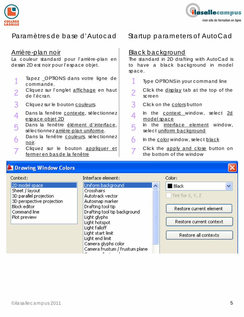
Arrière-plan noir La couleur standard pour l’arrière-plan en dessin 2D est noir pour l’espace objet.
Black background The standard in 2D drafting with AutoCad is to have a black background in model space.
1 Tapez _OPTIONS dans votre ligne de commande.
1 Type OPTIONS in your command line
2 Cliquez sur l’onglet affichage en haut de l’écran.
2 Click the display tab at the top of the screen
3 Cliquez sur le bouton couleurs. 3 Click on the colors button
4 Dans la fenêtre contexte, sélectionnez espace objet 2D
4 In the context window, select 2d model space
5 Dans la fenêtre élément d’interface, sélectionnez arrière-plan uniforme.
5 In the interface element window, select uniform background
6 Dans la fenêtre couleurs, sélectionnez noir.
6 In the color window, select black
7 Cliquez sur le bouton appliquer et fermer en bas de la fenêtre
7 Click the apply and close button on the bottom of the window
©ilasallecampus 2011
6
6
Paramètres de base d’Autocad Startup parameters of AutoCad
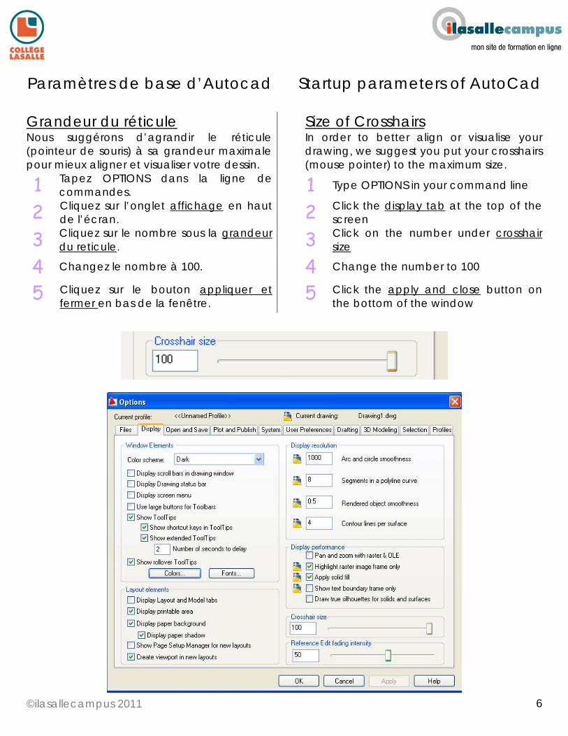
Grandeur du réticule Nous suggérons d’agrandir le réticule (pointeur de souris) à sa grandeur maximale pour mieux aligner et visualiser votre dessin.
Size of Crosshairs In order to better align or visualise your drawing, we suggest you put your crosshairs (mouse pointer) to the maximum size.
1 Tapez OPTIONS dans la ligne de commandes.
1 Type OPTIONS in your command line
2 Cliquez sur l’onglet affichage en haut de l’écran.
2 Click the display tab at the top of the screen
3 Cliquez sur le nombre sous la grandeur du reticule.
3 Click on the number under crosshair size
4 Changez le nombre à 100. 4 Change the number to 100
5 Cliquez sur le bouton appliquer et fermer en bas de la fenêtre.
5 Click the apply and close button on the bottom of the window
©ilasallecampus 2011
7
7
Paramètres de base d’Autocad Startup parameters of AutoCad
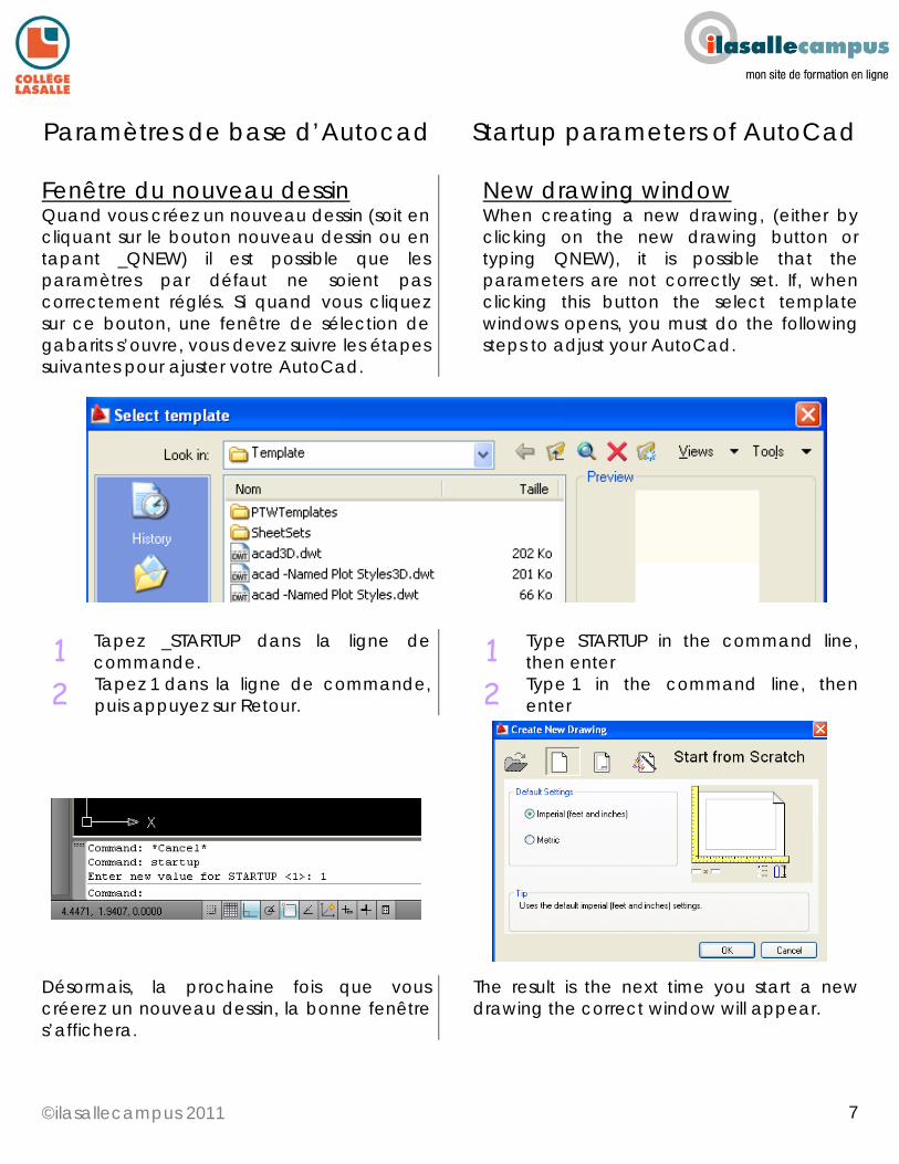
Fenêtre du nouveau dessin Quand vous créez un nouveau dessin (soit en cliquant sur le bouton nouveau dessin ou en tapant _QNEW) il est possible que les paramètres par défaut ne soient pas correctement réglés. Si quand vous cliquez sur ce bouton, une fenêtre de sélection de gabarits s’ouvre, vous devez suivre les étapes suivantes pour ajuster votre AutoCad.
New drawing window When creating a new drawing, (either by clicking on the new drawing button or typing QNEW), it is possible that the parameters are not correctly set. If, when clicking this button the select template windows opens, you must do the following steps to adjust your AutoCad.
1 Tapez _STARTUP dans la ligne de commande.
1 Type STARTUP in the command line, then enter
2 Tapez 1 dans la ligne de commande, puis appuyez sur Retour.
2 Type 1 in the command line, then enter
Désormais, la prochaine fois que vous créerez un nouveau dessin, la bonne fenêtre s’affichera.
The result is the next time you start a new drawing the correct window will appear.
©ilasallecampus 2011
8
8
Paramètres de base d’Autocad Startup parameters of AutoCad
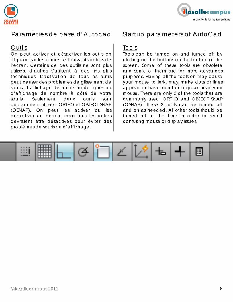
Outils On peut activer et désactiver les outils en cliquant sur les icônes se trouvant au bas de l’écran. Certains de ces outils ne sont plus utilisés, d’autres s’utilisent à des fins plus techniques. L’activation de tous les outils peut causer des problèmes de glissement de souris, d’affichage de points ou de lignes ou d’affichage de nombre à côté de votre souris. Seulement deux outils sont couramment utilisés : ORTHO et OBJECT SNAP (OSNAP). On peut les activer ou les désactiver au besoin, mais tous les autres devraient être désactivés pour éviter des problèmes de souris ou d’affichage.
Tools Tools can be turned on and turned off by clicking on the buttons on the bottom of the screen. Some of these tools are obsolete and some of them are for more advances purposes. Having all the tools on may cause your mouse to jerk, may make dots or lines appear or have number appear near your mouse. There are only 2 of the tools that are commonly used. ORTHO and OBJECT SNAP (OSNAP). These 2 tools can be turned off and on as needed. All other tools should be turned off all the time in order to avoid confusing mouse or display issues.
©ilasallecampus 2011
9
9
Paramètres de base d’Autocad Startup parameters of AutoCad
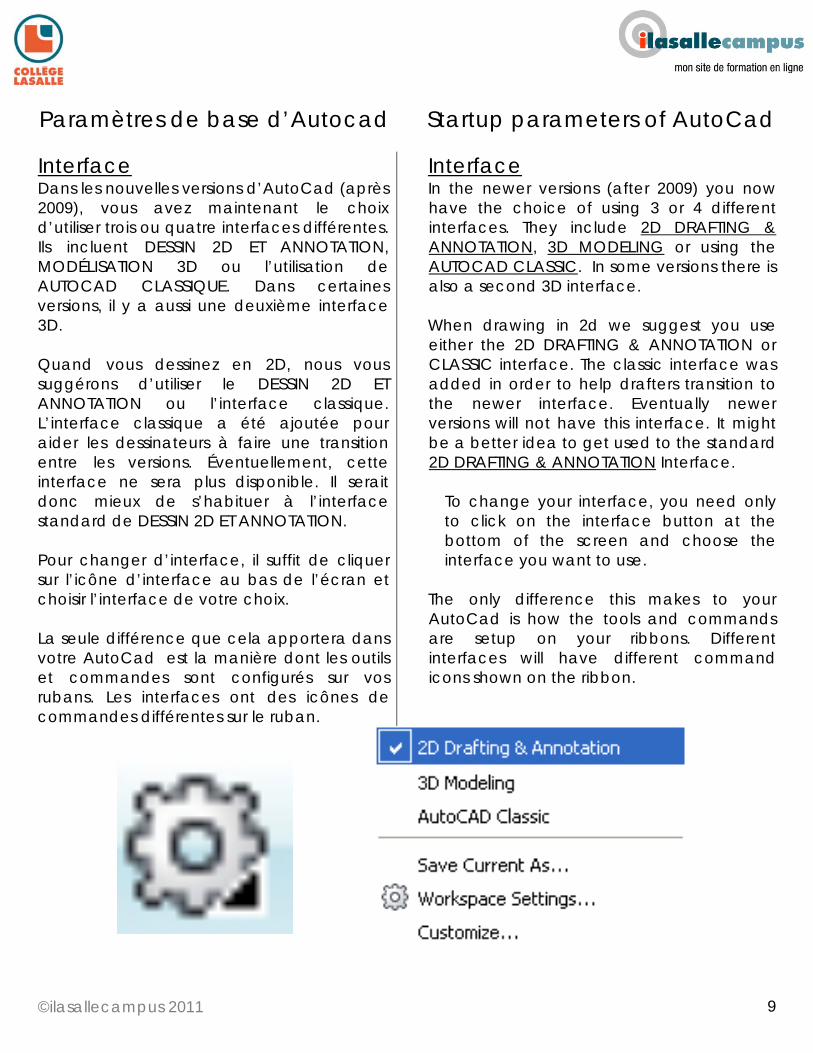
Interface Dans les nouvelles versions d’AutoCad (après 2009), vous avez maintenant le choix d’utiliser trois ou quatre interfaces différentes. Ils incluent DESSIN 2D ET ANNOTATION, MODÉLISATION 3D ou l’utilisation de AUTOCAD CLASSIQUE. Dans certaines versions, il y a aussi une deuxième interface 3D. Quand vous dessinez en 2D, nous vous suggérons d’utiliser le DESSIN 2D ET ANNOTATION ou l’interface classique. L’interface classique a été ajoutée pour aider les dessinateurs à faire une transition entre les versions. Éventuellement, cette interface ne sera plus disponible. Il serait donc mieux de s’habituer à l’interface standard de DESSIN 2D ET ANNOTATION. Pour changer d’interface, il suffit de cliquer sur l’icône d’interface au bas de l’écran et choisir l’interface de votre choix. La seule différence que cela apportera dans votre AutoCad est la manière dont les outils et commandes sont configurés sur vos rubans. Les interfaces ont des icônes de commandes différentes sur le ruban.
Interface In the newer versions (after 2009) you now have the choice of using 3 or 4 different interfaces. They include 2D DRAFTING & ANNOTATION, 3D MODELING or using the AUTOCAD CLASSIC. In some versions there is also a second 3D interface. When drawing in 2d we suggest you use either the 2D DRAFTING & ANNOTATION or CLASSIC interface. The classic interface was added in order to help drafters transition to the newer interface. Eventually newer versions will not have this interface. It might be a better idea to get used to the standard 2D DRAFTING & ANNOTATION Interface.
To change your interface, you need only to click on the interface button at the bottom of the screen and choose the interface you want to use.
The only difference this makes to your AutoCad is how the tools and commands are setup on your ribbons. Different interfaces will have different command icons shown on the ribbon.
©ilasallecampus 2011
10
10
Créer un Nouveau Dessin Starting a New Drawing
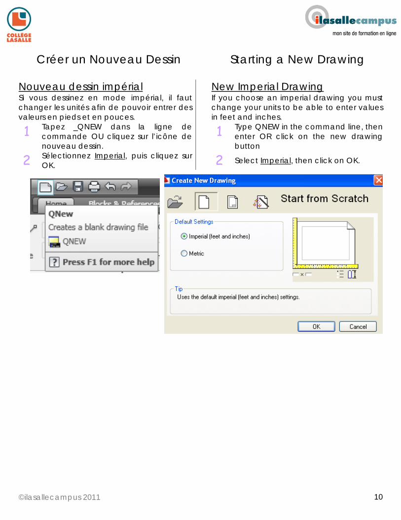
Nouveau dessin impérial Si vous dessinez en mode impérial, il faut changer les unités afin de pouvoir entrer des valeurs en pieds et en pouces.
New Imperial Drawing If you choose an imperial drawing you must change your units to be able to enter values in feet and inches.
1 Tapez _QNEW dans la ligne de commande OU cliquez sur l’icône de nouveau dessin.
1 Type QNEW in the command line, then enter OR click on the new drawing button
2 Sélectionnez Imperial, puis cliquez sur OK.
2 Select Imperial, then click on OK.
©ilasallecampus 2011
11
11
Créer un Nouveau Dessin Starting a New Drawing
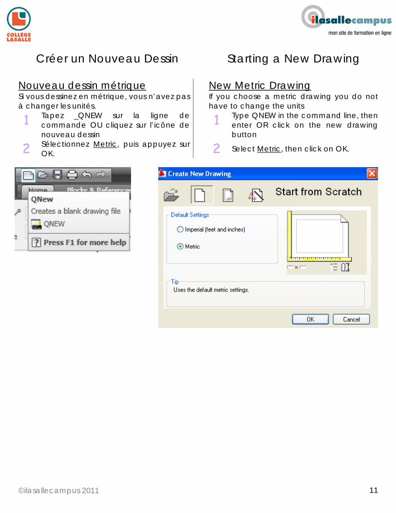
Nouveau dessin métrique Si vous dessinez en métrique, vous n’avez pas à changer les unités.
New Metric Drawing If you choose a metric drawing you do not have to change the units
1 Tapez _QNEW sur la ligne de commande OU cliquez sur l’icône de nouveau dessin
1 Type QNEW in the command line, then enter OR click on the new drawing button
2 Sélectionnez Metric, puis appuyez sur OK.
2 Select Metric, then click on OK.
©ilasallecampus 2011
12
12
Créer un Nouveau Dessin Starting a New Drawing
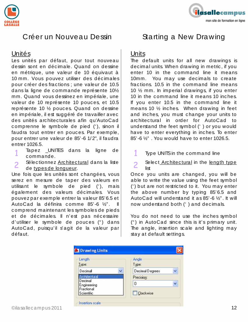
Unités Les unités par défaut, pour tout nouveau dessin sont en décimale. Quand on dessine en métrique, une valeur de 10 équivaut à 10 mm. Vous pouvez utiliser des décimales pour créer des fractions ; une valeur de 10.5 dans la ligne de commande représente 10½ mm. Quand vous dessinez en impériale, une valeur de 10 représente 10 pouces, et 10.5 représente 10 ½ pouces. Quand on dessine en impériale, il est suggéré de travailler avec des unités architecturales afin qu'AutoCad comprenne le symbole de pied (‘), sinon il faudra tout entrer en pouces. Par exemple, pour entrer une valeur de 85’-6 1/2", il faudra entrer 1026.5.
Units The default units for all new drawings is decimal units. When drawing in metric, if you enter 10 in the command line it means 10mm. You may use decimals to create fractions. 10.5 in the command line means 10 ½ mm. In imperial drawings, if you enter 10 in the command line it means 10 inches. If you enter 10.5 in the command line it means 10 ½ inches. When drawing in feet and inches, you must change your units to architectural in order for AutoCad to understand the feet symbol (‘ ) or you would have to enter everything in inches. To enter 85’-6 ½” . You would have to enter 1026.5.
1 Tapez _UNITES dans la ligne de commande.
1 Type UNITS in the command line
2 Sélectionnez Architectural dans la liste de types de longueur.
2 Select Architectural in the length type list
Une fois que les unités sont changées, vous serez en mesure de taper des valeurs en utilisant le symbole de pied (‘), mais également des valeurs décimales. Vous pouvez par exemple entrer la valeur 85’6.5 et AutoCad la définira comme 85’-6 ½”. Il comprend maintenant les symboles de pieds et de décimales. Il n’est pas nécessaire d’utiliser le symbole de pouces (“) dans AutoCad, puisqu’il s’agit de la valeur par défaut.
Once you units are changed, you will be able to write the value using the feet symbol (‘) but are not restricted to it. You may enter the above number by typing 85’6.5 and AutoCad will understand it as 85’-6 ½”. It will now understand both (‘ ) and decimals. You do not need to use the inches symbol (“) in AutoCad since this is it’s primary unit. The angle, insertion scale and lighting may stay at default settings.
©ilasallecampus 2011
13
13
Créer un Nouveau Dessin Starting a New Drawing
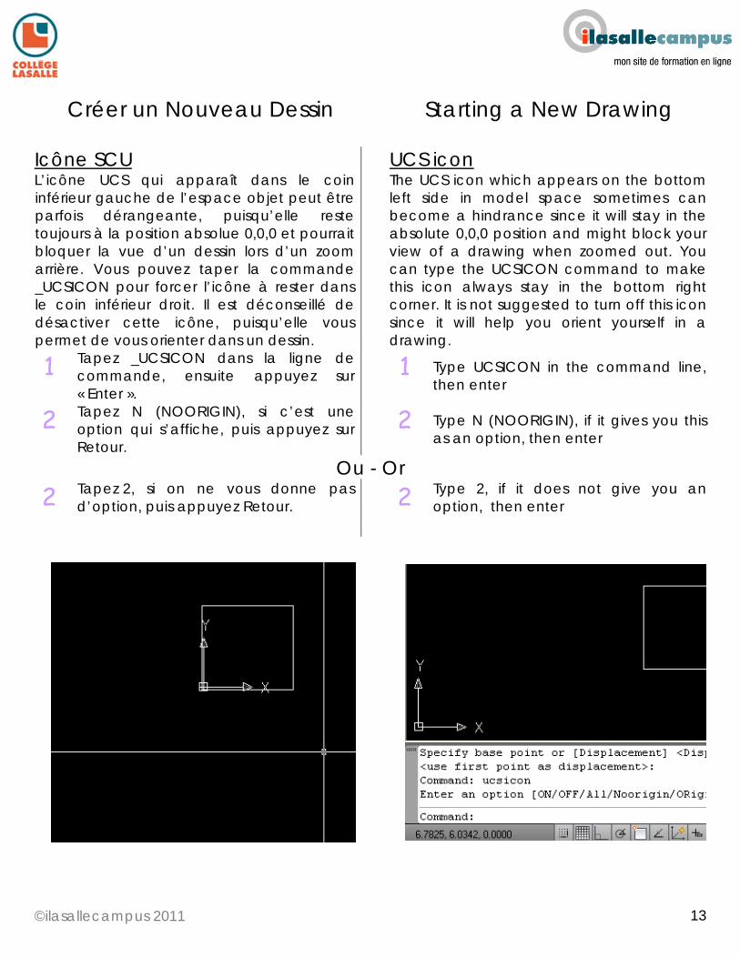
Icône SCU L’icône UCS qui apparaît dans le coin inférieur gauche de l’espace objet peut être parfois dérangeante, puisqu’elle reste toujours à la position absolue 0,0,0 et pourrait bloquer la vue d’un dessin lors d’un zoom arrière. Vous pouvez taper la commande _UCSICON pour forcer l’icône à rester dans le coin inférieur droit. Il est déconseillé de désactiver cette icône, puisqu’elle vous permet de vous orienter dans un dessin.
UCS icon The UCS icon which appears on the bottom left side in model space sometimes can become a hindrance since it will stay in the absolute 0,0,0 position and might block your view of a drawing when zoomed out. You can type the UCSICON command to make this icon always stay in the bottom right corner. It is not suggested to turn off this icon since it will help you orient yourself in a drawing.
1 Tapez _UCSICON dans la ligne de commande, ensuite appuyez sur « Enter ».
1 Type UCSICON in the command line, then enter
2 Tapez N (NOORIGIN), si c’est une option qui s’affiche, puis appuyez sur Retour.
2 Type N (NOORIGIN), if it gives you this as an option, then enter
Ou - Or 2 Tapez 2, si on ne vous donne pas
d’option, puis appuyez Retour. 2 Type 2, if it does not give you an
option, then enter
©ilasallecampus 2011
14
14
Créer un Nouveau Dessin Starting a New Drawing
Créer un gabarit personnel Un dessin AutoCad peut inclure une panoplie de choses différentes. On peut avoir des styles de cotes, des styles de texte, des styles de tableaux, des blocs, des calques, des onglets de présentations, et beaucoup plus encore. Pour les designers, il est très commun de créer un fichier .dwg qui contient tous les outils de travail dans un dessin et de tout simplement s’en servir comme gabarit. Pour créer votre propre gabarit, ouvrez un nouveau fichier, choisissez les mesures métriques ou impériales, changez les unités au besoin et utilisez le Design center pour importer vos styles, blocs ou mise en page dans votre dessin provenant d’autres dessins. Enregistrez-le ensuite sur votre ordinateur. La prochaine fois que vous créerez un nouveau dessin, plutôt que d’en créer un dans AutoCad, ouvrez le gabarit que vous avez créé et sauvegardez-le immédiatement sous un autre nom. Vous aurez ainsi tout ce dont vous avez besoin sous la main et gagnerez énormément de temps.
Creating a personal template AutoCad drawings can include a lot of different things. You may have dimension styles, text styles, table styles, title blocks, layers, page setups, blocks and many more things. For designers, it common to create a dwg file that has all the working tools included in one drawing and simply use it as a template. To create your own template, open a new file, pick whether it is metric or imperial, change your units, if needed, and using the design center, import your styles, layers, blocks and layouts into your drawing from other drawings. Save it somewhere on your computer. The next time you want to start a new drawing, instead of creating one in AutoCad, open this template file you created and immediately save it under another name. You will then have all the things you need already imported and will save a lot of time.
©ilasallecampus 2011
15
15
Créer un Nouveau Dessin Starting a New Drawing
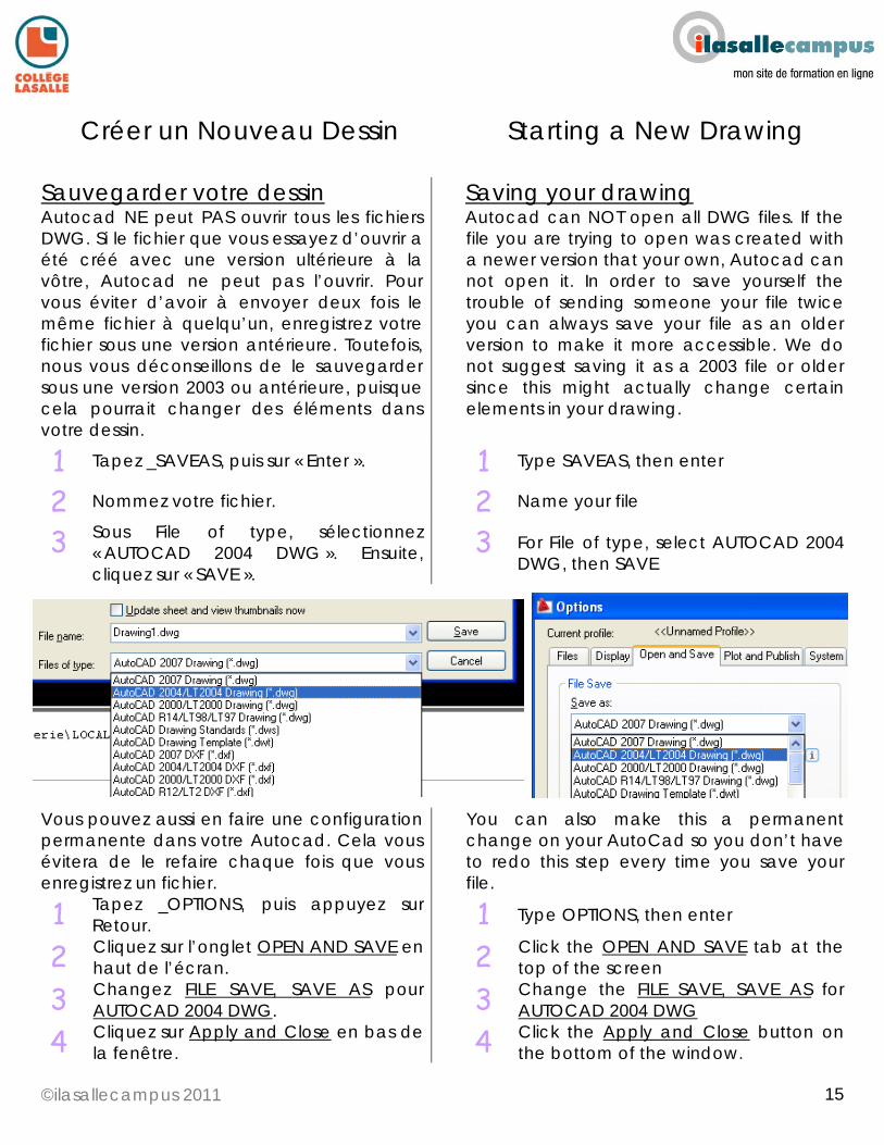
Sauvegarder votre dessin Autocad NE peut PAS ouvrir tous les fichiers DWG. Si le fichier que vous essayez d’ouvrir a été créé avec une version ultérieure à la vôtre, Autocad ne peut pas l’ouvrir. Pour vous éviter d’avoir à envoyer deux fois le même fichier à quelqu’un, enregistrez votre fichier sous une version antérieure. Toutefois, nous vous déconseillons de le sauvegarder sous une version 2003 ou antérieure, puisque cela pourrait changer des éléments dans votre dessin.
Saving your drawing Autocad can NOT open all DWG files. If the file you are trying to open was created with a newer version that your own, Autocad can not open it. In order to save yourself the trouble of sending someone your file twice you can always save your file as an older version to make it more accessible. We do not suggest saving it as a 2003 file or older since this might actually change certain elements in your drawing.
1 Tapez _SAVEAS, puis sur « Enter ». 1 Type SAVEAS, then enter
2 Nommez votre fichier. 2 Name your file
3 Sous File of type, sélectionnez « AUTOCAD 2004 DWG ». Ensuite, cliquez sur « SAVE ».
3 For File of type, select AUTOCAD 2004 DWG, then SAVE
Vous pouvez aussi en faire une configuration permanente dans votre Autocad. Cela vous évitera de le refaire chaque fois que vous enregistrez un fichier.
You can also make this a permanent change on your AutoCad so you don’t have to redo this step every time you save your file.
1 Tapez _OPTIONS, puis appuyez sur Retour.
1 Type OPTIONS, then enter
2 Cliquez sur l’onglet OPEN AND SAVE en haut de l’écran.
2 Click the OPEN AND SAVE tab at the top of the screen
3 Changez FILE SAVE, SAVE AS pour AUTOCAD 2004 DWG.
3 Change the FILE SAVE, SAVE AS for AUTOCAD 2004 DWG
4 Cliquez sur Apply and Close en bas de la fenêtre.
4 Click the Apply and Close button on the bottom of the window.
©ilasallecampus 2011
16
16
Blocs Blocks
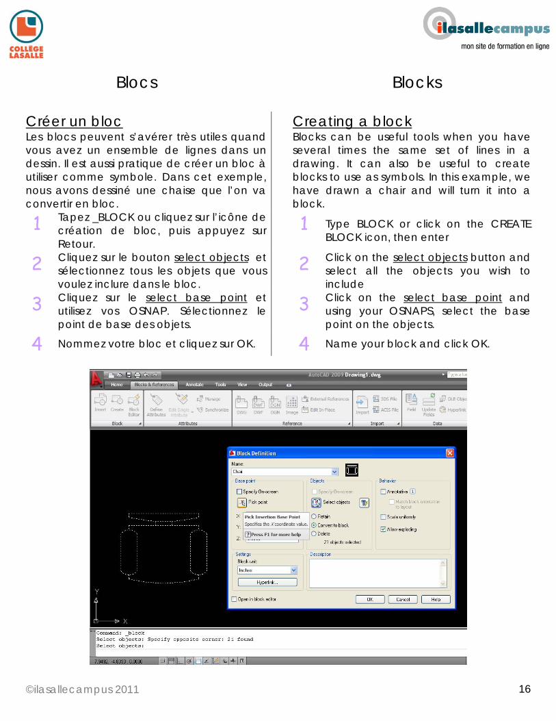
Créer un bloc Les blocs peuvent s’avérer très utiles quand vous avez un ensemble de lignes dans un dessin. Il est aussi pratique de créer un bloc à utiliser comme symbole. Dans cet exemple, nous avons dessiné une chaise que l’on va convertir en bloc.
Creating a block Blocks can be useful tools when you have several times the same set of lines in a drawing. It can also be useful to create blocks to use as symbols. In this example, we have drawn a chair and will turn it into a block.
1 Tapez _BLOCK ou cliquez sur l’icône de création de bloc, puis appuyez sur Retour.
1 Type BLOCK or click on the CREATE BLOCK icon, then enter
2 Cliquez sur le bouton select objects et sélectionnez tous les objets que vous voulez inclure dans le bloc.
2 Click on the select objects button and select all the objects you wish to include
3 Cliquez sur le select base point et utilisez vos OSNAP. Sélectionnez le point de base des objets.
3 Click on the select base point and using your OSNAPS, select the base point on the objects.
4 Nommez votre bloc et cliquez sur OK. 4 Name your block and click OK.
©ilasallecampus 2011
17
17
Blocs Blocks
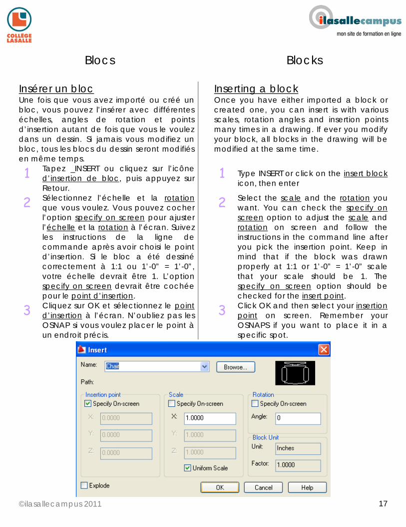
Insérer un bloc Une fois que vous avez importé ou créé un bloc, vous pouvez l’insérer avec différentes échelles, angles de rotation et points d’insertion autant de fois que vous le voulez dans un dessin. Si jamais vous modifiez un bloc, tous les blocs du dessin seront modifiés en même temps.
Inserting a block Once you have either imported a block or created one, you can insert is with various scales, rotation angles and insertion points many times in a drawing. If ever you modify your block, all blocks in the drawing will be modified at the same time.
1 Tapez _INSERT ou cliquez sur l’icône d’insertion de bloc, puis appuyez sur Retour.
1 Type INSERT or click on the insert block icon, then enter
2 Sélectionnez l’échelle et la rotation que vous voulez. Vous pouvez cocher l’option specify on screen pour ajuster l’échelle et la rotation à l’écran. Suivez les instructions de la ligne de commande après avoir choisi le point d’insertion. Si le bloc a été dessiné correctement à 1:1 ou 1’-0” = 1’-0”, votre échelle devrait être 1. L’option specify on screen devrait être cochée pour le point d’insertion.
2 Select the scale and the rotation you want. You can check the specify on screen option to adjust the scale and rotation on screen and follow the instructions in the command line after you pick the insertion point. Keep in mind that if the block was drawn properly at 1:1 or 1’-0” = 1’-0” scale that your scale should be 1. The specify on screen option should be checked for the insert point.
3 Cliquez sur OK et sélectionnez le point d’insertion à l’écran. N’oubliez pas les OSNAP si vous voulez placer le point à un endroit précis.
3 Click OK and then select your insertion point on screen. Remember your OSNAPS if you want to place it in a specific spot.
©ilasallecampus 2011
18
18
Blocs Blocks
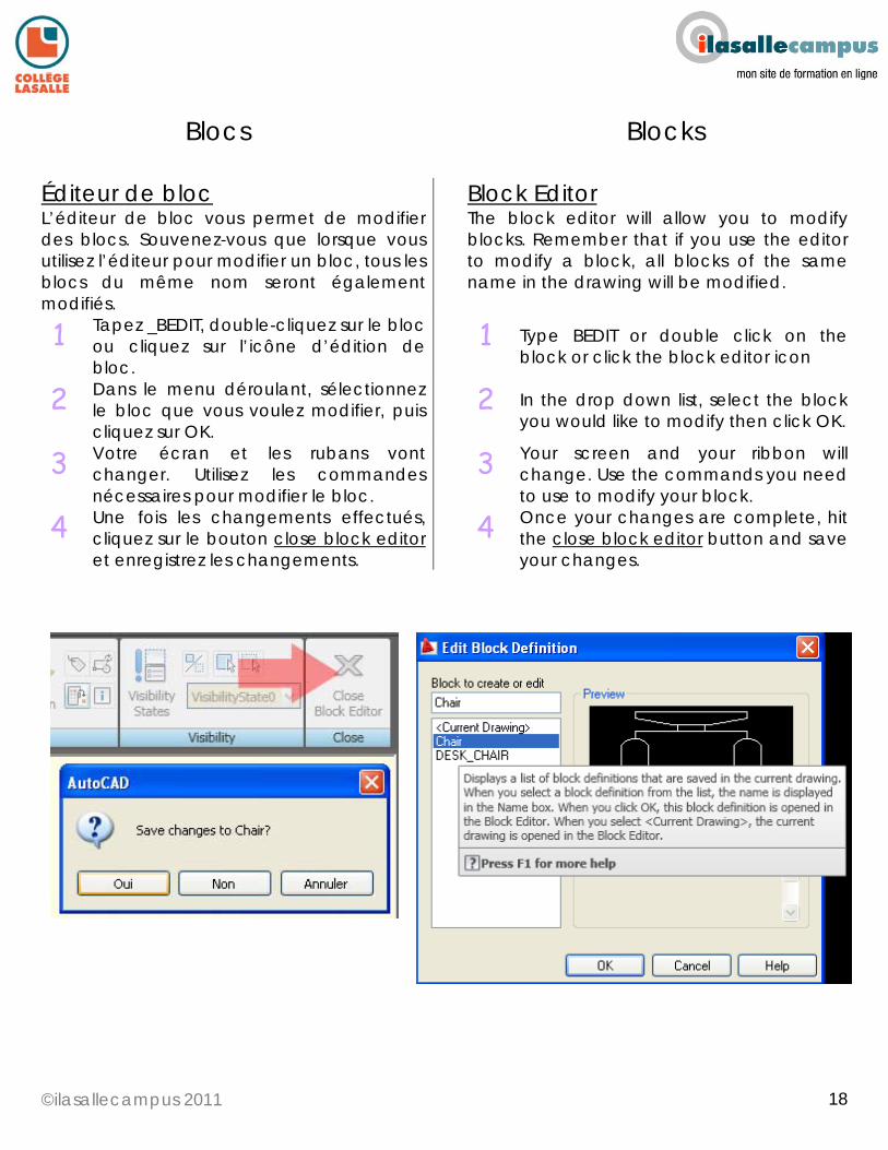
Éditeur de bloc L’éditeur de bloc vous permet de modifier des blocs. Souvenez-vous que lorsque vous utilisez l’éditeur pour modifier un bloc, tous les blocs du même nom seront également modifiés.
Block Editor The block editor will allow you to modify blocks. Remember that if you use the editor to modify a block, all blocks of the same name in the drawing will be modified.
1 Tapez _BEDIT, double-cliquez sur le bloc ou cliquez sur l’icône d’édition de bloc.
1 Type BEDIT or double click on the block or click the block editor icon
2 Dans le menu déroulant, sélectionnez le bloc que vous voulez modifier, puis cliquez sur OK.
2 In the drop down list, select the block you would like to modify then click OK.
3 Votre écran et les rubans vont changer. Utilisez les commandes nécessaires pour modifier le bloc.
3 Your screen and your ribbon will change. Use the commands you need to use to modify your block.
4 Une fois les changements effectués, cliquez sur le bouton close block editor et enregistrez les changements.
4 Once your changes are complete, hit the close block editor button and save your changes.
©ilasallecampus 2011
19
19
Blocs Blocks
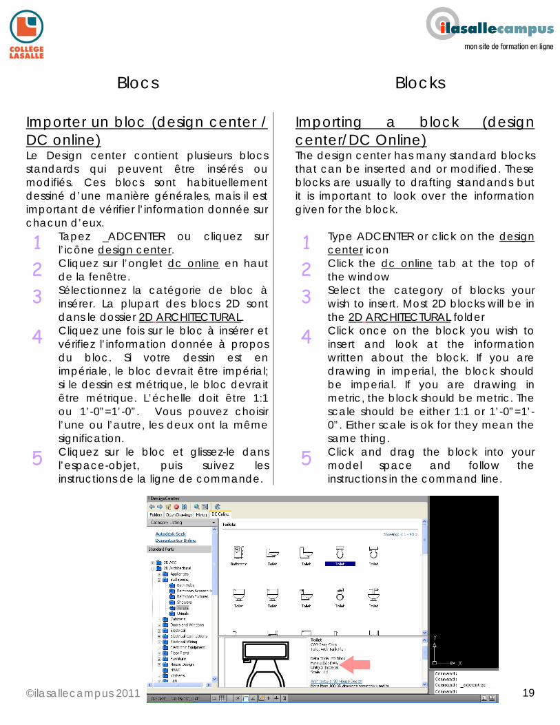
Importer un bloc (design center / DC online) Le Design center contient plusieurs blocs standards qui peuvent être insérés ou modifiés. Ces blocs sont habituellement dessiné d’une manière générales, mais il est important de vérifier l’information donnée sur chacun d’eux.
Importing a block (design center/DC Online) The design center has many standard blocks that can be inserted and or modified. These blocks are usually to drafting standands but it is important to look over the information given for the block.
1 Tapez _ADCENTER ou cliquez sur l’icône design center.
1 Type ADCENTER or click on the design center icon
2 Cliquez sur l’onglet dc online en haut de la fenêtre.
2 Click the dc online tab at the top of the window
3 Sélectionnez la catégorie de bloc à insérer. La plupart des blocs 2D sont dans le dossier 2D ARCHITECTURAL.
3 Select the category of blocks your wish to insert. Most 2D blocks will be in the 2D ARCHITECTURAL folder
4 Cliquez une fois sur le bloc à insérer et vérifiez l’information donnée à propos du bloc. Si votre dessin est en impériale, le bloc devrait être impérial; si le dessin est métrique, le bloc devrait être métrique. L’échelle doit être 1:1 ou 1’-0”=1’-0”. Vous pouvez choisir l’une ou l’autre, les deux ont la même signification.
4 Click once on the block you wish to insert and look at the information written about the block. If you are drawing in imperial, the block should be imperial. If you are drawing in metric, the block should be metric. The scale should be either 1:1 or 1’-0”=1’-0”. Either scale is ok for they mean the same thing.
5 Cliquez sur le bloc et glissez-le dans l’espace-objet, puis suivez les instructions de la ligne de commande.
5 Click and drag the block into your model space and follow the instructions in the command line.
©ilasallecampus 2011
20
20
Blocs Blocks
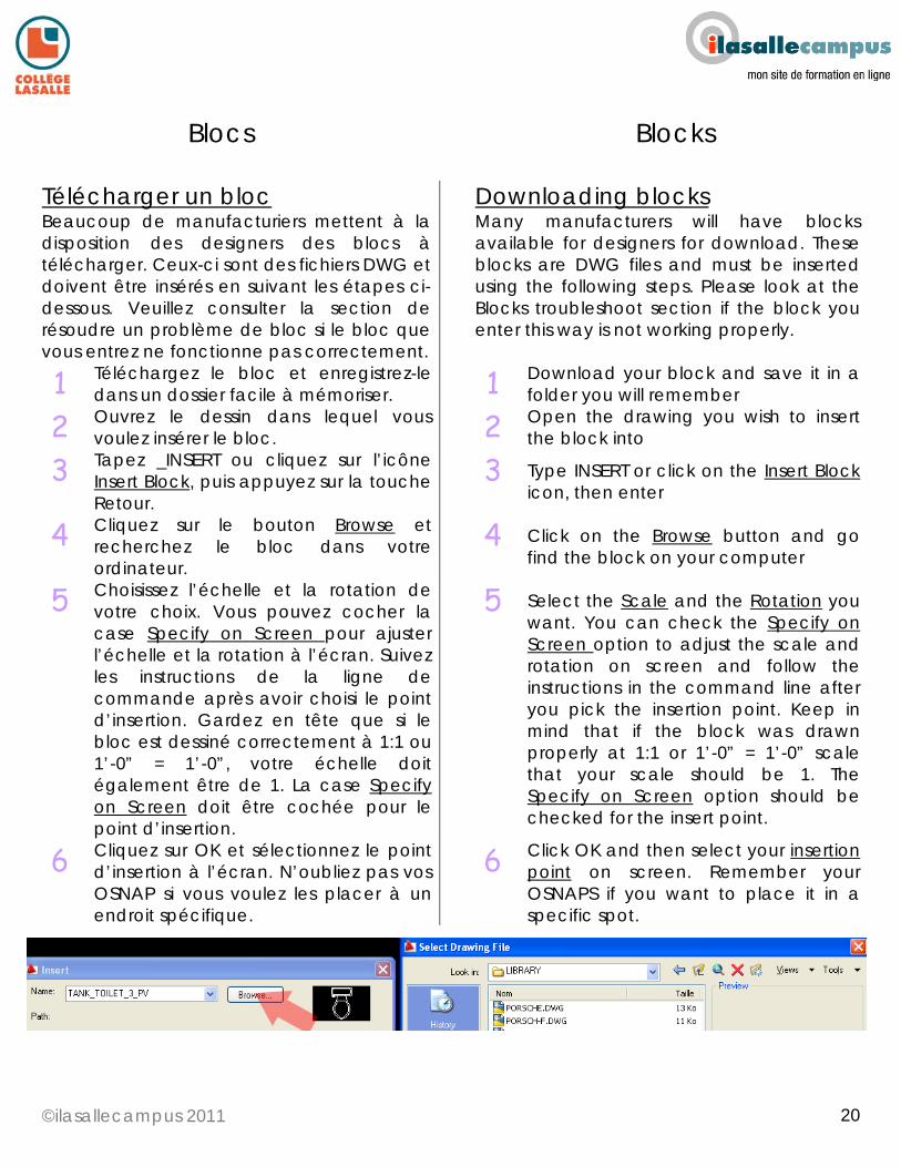
Télécharger un bloc Beaucoup de manufacturiers mettent à la disposition des designers des blocs à télécharger. Ceux-ci sont des fichiers DWG et doivent être insérés en suivant les étapes ci-dessous. Veuillez consulter la section de résoudre un problème de bloc si le bloc que vous entrez ne fonctionne pas correctement.
Downloading blocks Many manufacturers will have blocks available for designers for download. These blocks are DWG files and must be inserted using the following steps. Please look at the Blocks troubleshoot section if the block you enter this way is not working properly.
1 Téléchargez le bloc et enregistrez-le dans un dossier facile à mémoriser.
1 Download your block and save it in a folder you will remember
2 Ouvrez le dessin dans lequel vous voulez insérer le bloc.
2 Open the drawing you wish to insert the block into
3 Tapez _INSERT ou cliquez sur l’icône Insert Block, puis appuyez sur la touche Retour.
3 Type INSERT or click on the Insert Block icon, then enter
4 Cliquez sur le bouton Browse et recherchez le bloc dans votre ordinateur.
4 Click on the Browse button and go find the block on your computer
5 Choisissez l’échelle et la rotation de votre choix. Vous pouvez cocher la case Specify on Screen pour ajuster l’échelle et la rotation à l’écran. Suivez les instructions de la ligne de commande après avoir choisi le point d’insertion. Gardez en tête que si le bloc est dessiné correctement à 1:1 ou 1’-0” = 1’-0”, votre échelle doit également être de 1. La case Specify on Screen doit être cochée pour le point d’insertion.
5 Select the Scale and the Rotation you want. You can check the Specify on Screen option to adjust the scale and rotation on screen and follow the instructions in the command line after you pick the insertion point. Keep in mind that if the block was drawn properly at 1:1 or 1’-0” = 1’-0” scale that your scale should be 1. The Specify on Screen option should be checked for the insert point.
6 Cliquez sur OK et sélectionnez le point d’insertion à l’écran. N’oubliez pas vos OSNAP si vous voulez les placer à un endroit spécifique.
6 Click OK and then select your insertion point on screen. Remember your OSNAPS if you want to place it in a specific spot.
©ilasallecampus 2011
21
21
Blocs Blocks
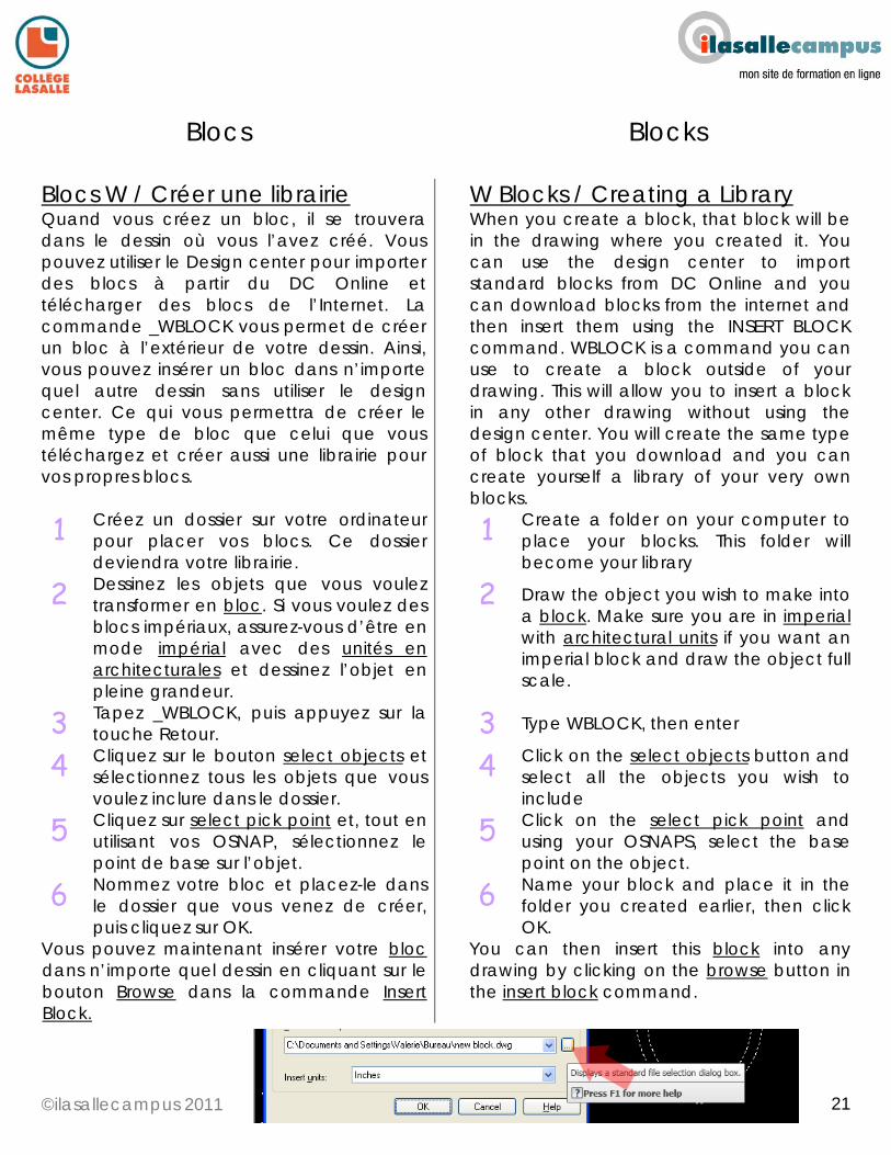
Blocs W / Créer une librairie Quand vous créez un bloc, il se trouvera dans le dessin où vous l’avez créé. Vous pouvez utiliser le Design center pour importer des blocs à partir du DC Online et télécharger des blocs de l’Internet. La commande _WBLOCK vous permet de créer un bloc à l’extérieur de votre dessin. Ainsi, vous pouvez insérer un bloc dans n’importe quel autre dessin sans utiliser le design center. Ce qui vous permettra de créer le même type de bloc que celui que vous téléchargez et créer aussi une librairie pour vos propres blocs.
W Blocks / Creating a Library When you create a block, that block will be in the drawing where you created it. You can use the design center to import standard blocks from DC Online and you can download blocks from the internet and then insert them using the INSERT BLOCK command. WBLOCK is a command you can use to create a block outside of your drawing. This will allow you to insert a block in any other drawing without using the design center. You will create the same type of block that you download and you can create yourself a library of your very own blocks.
1 Créez un dossier sur votre ordinateur pour placer vos blocs. Ce dossier deviendra votre librairie.
1 Create a folder on your computer to place your blocks. This folder will become your library
2 Dessinez les objets que vous voulez transformer en bloc. Si vous voulez des blocs impériaux, assurez-vous d’être en mode impérial avec des unités en architecturales et dessinez l’objet en pleine grandeur.
2 Draw the object you wish to make into a block. Make sure you are in imperial with architectural units if you want an imperial block and draw the object full scale.
3 Tapez _WBLOCK, puis appuyez sur la touche Retour.
3 Type WBLOCK, then enter
4 Cliquez sur le bouton select objects et sélectionnez tous les objets que vous voulez inclure dans le dossier.
4 Click on the select objects button and select all the objects you wish to include
5 Cliquez sur select pick point et, tout en utilisant vos OSNAP, sélectionnez le point de base sur l’objet.
5 Click on the select pick point and using your OSNAPS, select the base point on the object.
6 Nommez votre bloc et placez-le dans le dossier que vous venez de créer, puis cliquez sur OK.
6 Name your block and place it in the folder you created earlier, then click OK.
Vous pouvez maintenant insérer votre bloc dans n’importe quel dessin en cliquant sur le bouton Browse dans la commande Insert Block.
You can then insert this block into any drawing by clicking on the browse button in the insert block command.
©ilasallecampus 2011
22
22
Blocs Blocks
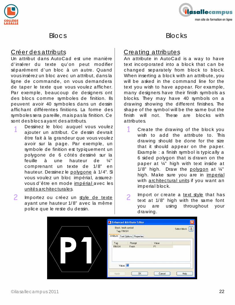
Créer des attributs Un attribut dans AutoCad est une manière d’insérer du texte qu’on peut modifier séparément d’un bloc à un autre. Quand vous insérez un bloc avec un attribut, dans la ligne de commande, on vous demandera de taper le texte que vous voulez afficher. Par exemple, beaucoup de designers ont des blocs comme symboles de finition. Ils peuvent avoir 40 symboles dans un dessin affichant différentes finitions. La forme des symboles sera pareille, mais pas la finition. Ce sont des blocs ayant des attributs.
Creating attributes An attribute in AutoCad is a way to have text incorporated into a block that can be changed separately from block to block. When inserting a block with an attribute, you will be asked in the command line for the text you wish to have appear. For example, many designers have their finish symbols as blocks. They may have 40 symbols on a drawing showing the different finishes. The shape of the symbol will be the same but the finish will not. These are blocks with attributes.
1 Dessinez le bloc auquel vous voulez ajouter un attribut. Ce dessin devrait être fait à la grandeur que vous voulez avoir sur la page. Par exemple, un symbole de finition est typiquement un polygone de 6 côtés dessiné sur la feuille à une hauteur de ¼” comprenant un texte de 1/8” en hauteur. Dessinez le polygone à 1/4". Si vous voulez un bloc impérial, assurez-vous d’être en mode impérial avec les unités architecturales.
1 Create the drawing of the block you wish to add the attribute to. This drawing should be done for the size that it should appear on the paper. Example : a finish symbol is typically a 6 sided polygon that is drawn on the paper at ¼” high with text inside at 1/8” high. Draw the polygon at ¼” high. Make sure you are in imperial with architectural units if you want an imperial block.
2 Importez ou créez un style de texte ayant une hauteur 1/8” avec la même police que le reste du dessin.
2 Import or create a text style that has text at 1/8” high with the same font you are using throughout your drawing.
©ilasallecampus 2011
23
23
Blocs Blocks
Créer des attributs (suite) Creating attributes con’t
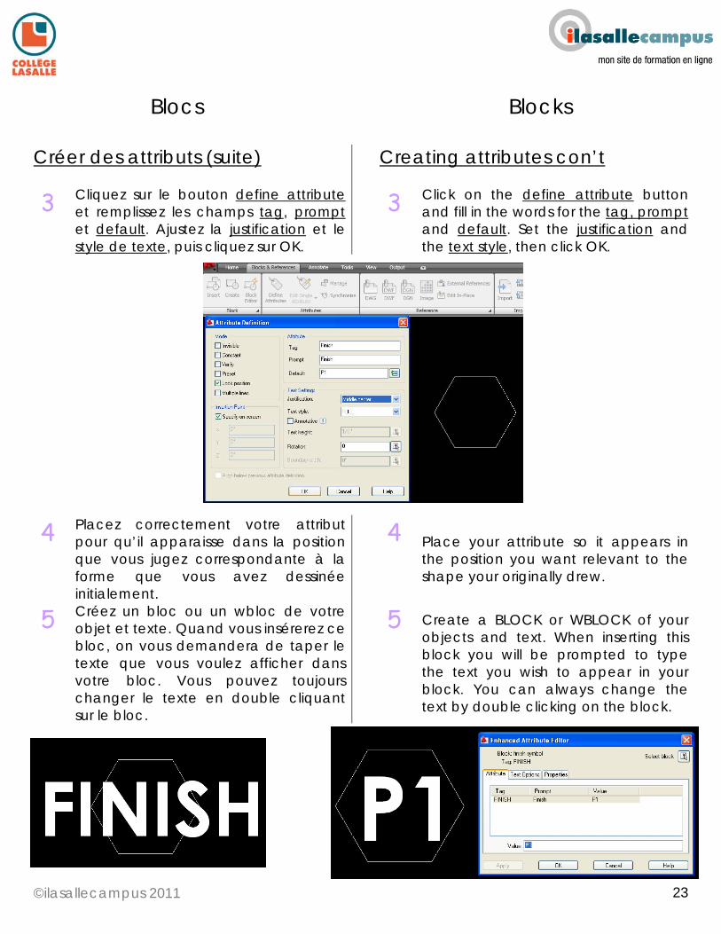
3 Cliquez sur le bouton define attribute et remplissez les champs tag, prompt et default. Ajustez la justification et le style de texte, puis cliquez sur OK.
3 Click on the define attribute button and fill in the words for the tag, prompt and default. Set the justification and the text style, then click OK.
4 Placez correctement votre attribut pour qu’il apparaisse dans la position que vous jugez correspondante à la forme que vous avez dessinée initialement.
4 Place your attribute so it appears in the position you want relevant to the shape your originally drew.
5 Créez un bloc ou un wbloc de votre objet et texte. Quand vous insérerez ce bloc, on vous demandera de taper le texte que vous voulez afficher dans votre bloc. Vous pouvez toujours changer le texte en double cliquant sur le bloc.
5 Create a BLOCK or WBLOCK of your objects and text. When inserting this block you will be prompted to type the text you wish to appear in your block. You can always change the text by double clicking on the block.
©ilasallecampus 2011
24
24
Blocs Blocks
Créer un cartouche Les cartouches sont un mélange de lignes et de textes dessinés sur une feuille à sa cote actuelle. Ils peuvent être transformés en blocs avec ou sans attributs pour permettre leur utilisation dans différents dessins.
Creating a title block Title blocks are a mixture of lines and text that are drawn in paper space to the actual size. They can be turned into blocks with and without attributes in order to use in different drawings.
1 Ouvrez un nouvel onglet de mise en page.
1 Open a new layout tab
2 Ajustez la mise en page pour que la page soit à la dimensions appropriée et à l’échelle 1:1 en pouces pour un dessin impérial, OU 1:1 mm pour un dessin métrique.
2 Do your page setup so that your page is the correct size and at 1:1 scale in inches for an imperial drawing OR mm for a metric one.
3 Dessinez un rectangle sur la feuille avec les mêmes dimensions que votre page. Si la grandeur de la page que vous choisissez est de 11x17, dessinez un rectangle de 11x17. Celui-ci servira d’exemple pour le décalage de vos lignes. Alignez ce rectangle avec la page. Il faut faire un zoom en avant, car OSNAP ne fonctionne pas sur la page blanche.
3 Draw a rectangle in paper space that is the same size as your page. If the page size you choose is 11 x 17, make a rectangle that is 11 x 17. This rectangle will serve as a base for offsetting your lines. Align this rectangle with your page. You will have to zoom in for this because OSNAP does not work with the white page.
4 Décalez le rectangle de ½”. Ainsi, le cadrage du cartouche se créera. La ligne devrait être à l’intérieur de la ligne tiretée. Si elle ne l’est pas, ajustez-la. Elle devrait être plus épaisse que toutes les autres lignes dans le dessin. Tapez _PE pour avoir la commande polyligne edit et ajoutez une largeur à la polyligne. Pour un cartouche de 11X17, .1 fonctionne bien pour des dessins impériaux de 11x17.
4 Offset your rectangle by ½”. This will create the boarder of your title block. This line should be inside the dashed line. If it is not, adjust it so it is. This line should be thicker than anything else on your drawing. Type PE for the polyline edit command and add a width to your polyline. For an 11x17 title block .1 wide works well for 11x17 imperial drawings
5 Dessinez une polyligne à +/-2” à partir de la marge de la page. Le cartouche se créera. Cette ligne devrait être épaisse. Encore une fois, utilisez la commande _PE, une largeur de .08 fonctionne bien avec des dessins impériaux de 11X17.
5 Draw a polyline +/-2” from the border of the page. This will create the title block. This line should also be thicker. Again, use the PE command the change the width. .08 works well for 11x17 imperial drawings.
©ilasallecampus 2011
25
25
Blocs Blocks
Créer un cartouche (suite) Creating a title block con’t
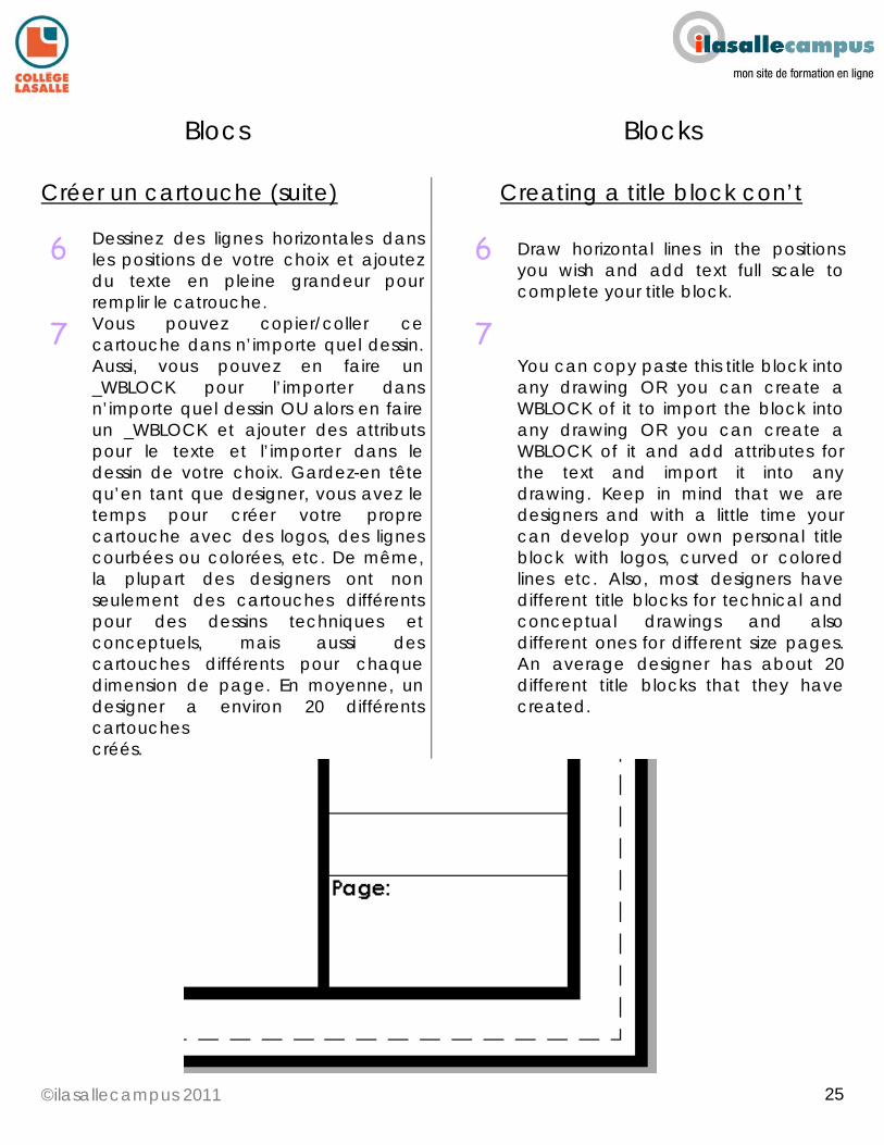
6 Dessinez des lignes horizontales dans les positions de votre choix et ajoutez du texte en pleine grandeur pour remplir le catrouche.
6 Draw horizontal lines in the positions you wish and add text full scale to complete your title block.
7 Vous pouvez copier/coller ce cartouche dans n’importe quel dessin. Aussi, vous pouvez en faire un _WBLOCK pour l’importer dans n’importe quel dessin OU alors en faire un _WBLOCK et ajouter des attributs pour le texte et l’importer dans le dessin de votre choix. Gardez-en tête qu’en tant que designer, vous avez le temps pour créer votre propre cartouche avec des logos, des lignes courbées ou colorées, etc. De même, la plupart des designers ont non seulement des cartouches différents pour des dessins techniques et conceptuels, mais aussi des cartouches différents pour chaque dimension de page. En moyenne, un designer a environ 20 différents cartouches créés.
7 You can copy paste this title block into any drawing OR you can create a WBLOCK of it to import the block into any drawing OR you can create a WBLOCK of it and add attributes for the text and import it into any drawing. Keep in mind that we are designers and with a little time your can develop your own personal title block with logos, curved or colored lines etc. Also, most designers have different title blocks for technical and conceptual drawings and also different ones for different size pages. An average designer has about 20 different title blocks that they have created.
©ilasallecampus 2011
26
26
Blocs Blocks
Résoudre un problème de bloc • Aucun bloc ne s’affiche dans la section DC ONLINE du DESIGN CENTER. Quand vous cliquez sur DC Online, vous avez besoin d’être connecté à Internet. Si c’est la première fois que vous ouvrez DC Online, il faudra cliquer sur GET BLOCS pour vous connecter au serveur. • Quand je télécharge un bloc d’un fabricant ou d’une autre source, il n’apparaît pas. Le bloc que vous essayez d’insérer pourrait se trouver dans votre dessin, mais vous ne le voyez pas parce que vous avez fait beaucoup trop de zoom avant ou arrière. Insérez le bloc de nouveau en utilisant OSNAP et faites attention à l’endroit où vous cliquez pour le point d’insertion. Faites ensuite un zoom avant sur le point pour voir si votre bloc est présent. S’il ne l’est pas, faites un zoom en arrière en double cliquant sur la boule de votre souris pour faire un zoom étendu. Si votre bloc ne s’affiche toujours pas, vérifiez votre calque pour voir s’il est actif. • J’ai importé un bloc à partir du Design center et il n’est pas de la bonne grandeur, il contient trop de lignes, manque une ligne que j’aimerais avoir OU ne correspond pas exactement à ce que je recherche. Importez le bloc, éclatez-le et changez les éléments selon vos désirs. Recréez un nouveau bloc sous un autre nom et vous aurez exactement ce que vous cherchez. Les blocs dans le Design center sont des blocs standards de base qui ne fonctionnent pas dans toutes les situations.
Blocks trouble shoot • I don’t have any blocks in the DC ONLINE portion of the DESIGN CENTER. When you click on DC Online you must be connected to the internet. If this is the first time you open DC Online you may have to click on the GET BLOCKS in order to connect to the server. • When I insert a block downloaded from a manufacturer or other online source, my block does not appear. The block you are trying to insert may be inserted into your drawing but you can’t see it because you are too zoomed out or too zoomed in. Insert the block again using OSNAP and pay attention to where you click for the insertion point. Then zoom in to that point to see if your block is there. If it is not, zoom out by double clicking on the scroll ball of your mouse to do a zoom extents. If you still don’t see your block check to make sure your active layer is turned on. • I imported a block from the design center and it is not the right size…. has too many lines …. Is missing a line I need OR is not exactly what I want. Import the block, explode it, then change what you want to change. Recreate a new block with another name and you will have exactly what you want. Blocks in the design center are standard base blocks and do not function in every situation.
©ilasallecampus 2011
27
27
Bloc Blocks
Résoudre un problème de bloc • Quand j’insère un bloc téléchargé d’un fabricant ou d’une autre source en ligne, mon bloc n’est pas de la bonne grandeur. Beaucoup de choses peuvent être à l’origine de cela. 1. Il se peut que le bloc soit de la bonne grandeur, mais pas le dessin.2. Il se peut que vous ayez changé l’échelle de votre bloc lors de son insertion. Sélectionnez le bloc et vérifiez son échelle dans la fenêtre des propriétés. 3. Le bloc que vous insérez ne correspond pas aux unités de votre dessin (insérer un bloc métrique dans un dessin impérial ou vice versa). 4. Le bloc n’est pas correctement dessiné et vous devez utiliser la commande de l’échelle. Pour les raisons 3 et 4, référez-vous à la section de la commande échelle avec référence de ce guide. • J’ai téléchargé un bloc et je ne le retrouve pas sur mon ordinateur. Dans Windows, faites une recherche de *.dwg et vous aurez tous les fichiers AutoCad se trouvant dans votre ordinateur. Si vous ne le retrouvez toujours pas, il faudra le télécharger de nouveau. • Le bloc que j’ai inséré n’est pas de la couleur par défaut du calque dans lequel je l’ai placé. Tous les objets dans AutoCad auront la couleur du calque à moins qu’ils soient spécifiés autrement. Si votre bloc n’a pas la couleur du calque, il faudra utiliser l’éditeur de bloc. Sélectionnez toutes les lignes et réglez la couleur PAR CALQUE. Sauvegardez les changements et a couleur devrait être la même que celle du calque. N’oubliez pas que certains blocs contiennent d’autres blocs. Si tel est le cas, il faudra les exclater du bloc principal. N’extrayez PAS le bloc initial. Vous pouvez ajuster les couleurs du bloc pour qu’elles soient du même style que votre dessin, ce qui vous permettra d'avoir plus d’une épaisseur de trait dans votre bloc. Dans ce cas, le bloc n’aura pas la couleur du calque.
Blocks trouble shoot • When I insert a block downloaded from a manufacturer or other online source, my block is not the right size. There are several reasons why this could happen. 1, your block is OK and your drawing is not. 2, You changed the scale of your block. Look in the properties window with the block selected and double check the scale of the block. 3, The block you are inserting is not meant for the units of your drawing. (inserting a metric block into an imperial drawing or vice versa)4, the block is not drawn properly and you must use the scale command. For reason 3 or 4, refer to the Scale reference portion of this guide. • I downloaded a block and I can’t find it on my computer. In windows do a search for *.dwg and this will show you all AutoCad files you have on your computer. If you still can’t find it you will have to download the block again. • The block I inserted is not using the default color of the layer I placed it on. As with all objects in AutoCad, they will take the color of the layer unless otherwise specified. If your block is not taking the color of the layer you will need to use the block editor, select all the lines and set the color to BY LAYER. Save your block and the color should change to the color of the layer it’s on. Keep in mind some blocks have blocks included therefore you may have to explode the blocks that are inside the main block. Do NOT explode the original block. You can also adjust the colors in the block to follow your plot styles so you have more than one lineweight in your block… in this case the block may not take the color of the layer.
©ilasallecampus 2011
28
28
Design Center
Importer des calques, blocs, etc. À partir du Design center, vous pouvez importer plusieurs éléments.
Importing layers, layouts, etc… From the design center ADCENTER you can add many things.
1 Ouvrez le Design center en tapant _ADCENTER ou en cliquant sur l’icône correspondante.
1 Open the design center by typing ADCENTER or clicking on the icon
2 Sélectionnez l’onglet de dossiers en haut de la fenêtre.
2 Select the folders tab at the top of the window.
3 Recherchez le fichier à partir duquel vous voulez importer des éléments. Vous pouvez ouvrir un dossier (pour voir ce qu’il contient en cliquant sur le signe + se trouvant devant le nom.
3 Search for the file you wish to import something from. You can open a folder (to see what is in it by clicking on the + symbol before the name.
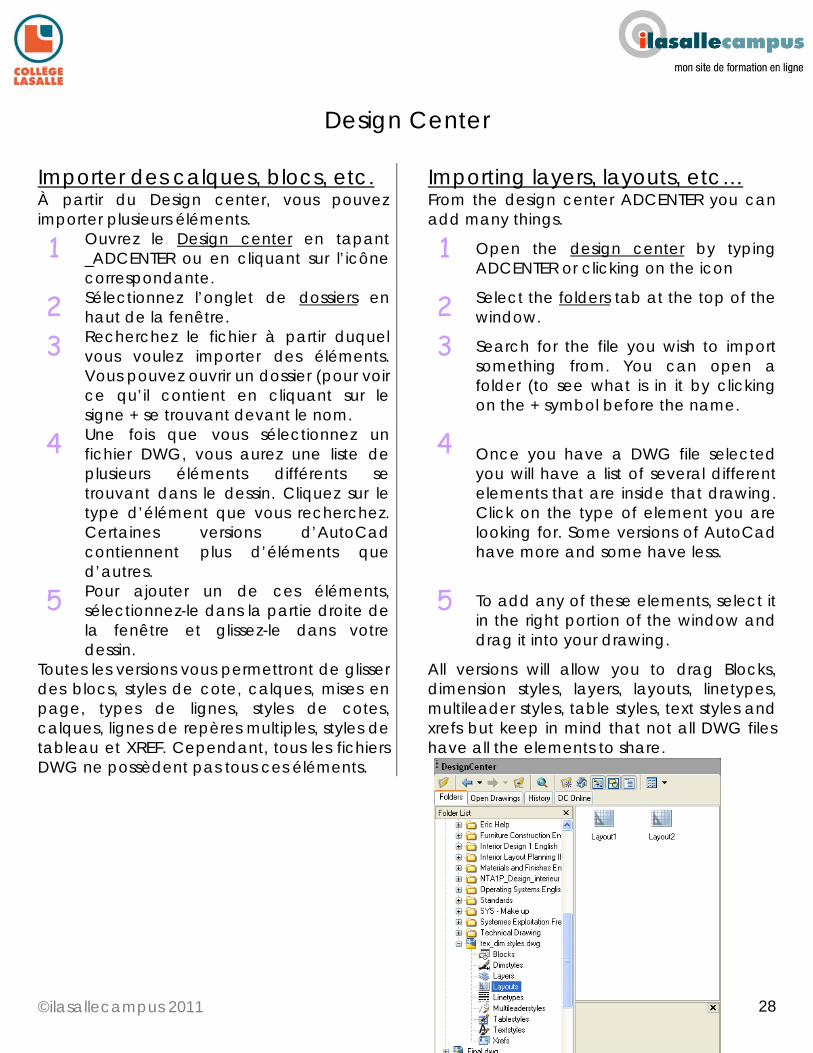
4 Une fois que vous sélectionnez un fichier DWG, vous aurez une liste de plusieurs éléments différents se trouvant dans le dessin. Cliquez sur le type d’élément que vous recherchez. Certaines versions d’AutoCad contiennent plus d’éléments que d’autres.
4 Once you have a DWG file selected you will have a list of several different elements that are inside that drawing. Click on the type of element you are looking for. Some versions of AutoCad have more and some have less.
5 Pour ajouter un de ces éléments, sélectionnez-le dans la partie droite de la fenêtre et glissez-le dans votre dessin.
5 To add any of these elements, select it in the right portion of the window and drag it into your drawing.
Toutes les versions vous permettront de glisser des blocs, styles de cote, calques, mises en page, types de lignes, styles de cotes, calques, lignes de repères multiples, styles de tableau et XREF. Cependant, tous les fichiers DWG ne possèdent pas tous ces éléments.
All versions will allow you to drag Blocks, dimension styles, layers, layouts, linetypes, multileader styles, table styles, text styles and xrefs but keep in mind that not all DWG files have all the elements to share.
©ilasallecampus 2011
29
29
Cotation Dimensions
Dessiner une cote Les cotes sont très importantes dans un dessin technique et doivent suivre les standards de dessin.
Drawing dimensions Dimensions are very important in technical 2D drawings and must be to drafting standards.
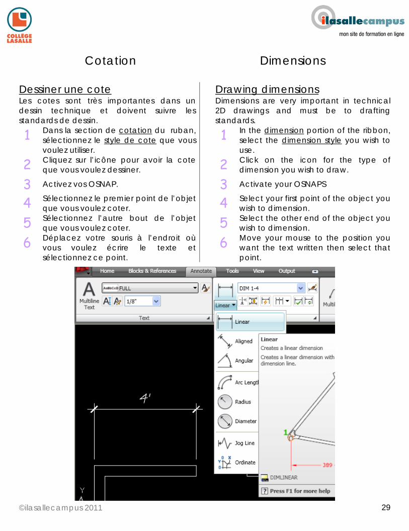
1 Dans la section de cotation du ruban, sélectionnez le style de cote que vous voulez utiliser.
1 In the dimension portion of the ribbon, select the dimension style you wish to use.
2 Cliquez sur l’icône pour avoir la cote que vous voulez dessiner.
2 Click on the icon for the type of dimension you wish to draw.
3 Activez vos OSNAP. 3 Activate your OSNAPS
4 Sélectionnez le premier point de l’objet que vous voulez coter.
4 Select your first point of the object you wish to dimension.
5 Sélectionnez l’autre bout de l’objet que vous voulez coter.
5 Select the other end of the object you wish to dimension.
6 Déplacez votre souris à l’endroit où vous voulez écrire le texte et sélectionnez ce point.
6 Move your mouse to the position you want the text written then select that point.
©ilasallecampus 2011
30
30
Cotation Dimensions
Modifier une cote Les cotes ne sont pas faciles à modifier. Gardez en tête que le OSNAP des cotes ne devrait JAMAIS être modifié, puisque la cote ne sera plus modifiable ni correcte.
Modifying dimensions Dimensions are very tricky to modify. You must keep in mind that the OSNAP point of the dimensions should NEVER be modified since this will cause the dimension to no longer be modifiable or accurate.
* Si vous voulez modifier la mesure de la cote, vous pouvez cliquer sur la cote et déplacer les poignées bleues dans un autre endroit. Si vous utilisez cette technique, vous devez activer les OSNAP quand vous choisissez l’autre endroit.
* If you want to modify what your dimension is dimensioning you may click on the dimension and move the blue grips to another location. If you change your dimension this way you must still use OSNAP when selecting the other location.
* Si vous voulez déplacer le texte plus loin ou plus près du dessin, vous pouvez sélectionner les poignées bleues aussi.
* If you want to move the text closer or further from the drawing you can select the Blue grips as well.
* Si vous voulez dessiner d’autres cotes alignées avec celles déjà dessinées, vous pouvez utiliser la commande de cote continue.
* If you want to draw more dimensions to aligned with a the dimensions you already drew you can use the continue dimension command.
* Si vous voulez modifier le style de la cote après avoir dessiné une cote, sélectionnez la cote et cliquez sur le bouton droit de votre souris. Sélectionnez ensuite le style de cote, puis choisissez le style approprié.
* If you want to change the dimension style after you have drawn a dimension, select the dimension(s) and right click on your mouse. Select dimension style and select the correct style.
* Si vous dessinez une cote sans l’activation des OSNAP, votre cote ne sera pas utilisable puisqu’il n’est pas précis. Si votre cote n’est pas de la bonne grandeur, c’est que vous n’avez pas choisi le bon style de cote. La couleur de la cote peut être la même que celle du calque, à moins qu’elle soit définie autrement dans le style de cote.
* If a dimension is drawn without OSNAP active, your dimension is then useless since it is not accurate. If your dimension is not the right size, it is because you did not use the correct dimension style. The color of the dimension can follow the color of the layer unless otherwise changed in the dimension style.
©ilasallecampus 2011
31
31
Cotation Dimensions
Choisir un style de cote Quand vous dessinez des cotes dans AutoCad, vous devez d’abord choisir le style de cote. Sans style de cote, il est presque impossible de dessiner une cote qui suit les règles de dessin standard. Un style de cote est un ensemble de paramètres prédéfinis qui détermine l’apparence de la cote une fois dessinée. Il inclut du texte, des couleurs, des unités et plusieurs autres éléments notamment la grandeur. Pour choisir un style, il faut comprendre les principes de dessin dans AutoCad. Quand vous dessinez dans AutoCad, vous le faites à pleine échelle. Par exemple, on a une pièce qui mesure 10’-0” x 10.’-0” est dessinée à 10’-0” x 10.’-0”. Ces dimensions ne rentrent pas sur une page de 11 x 17, parce la page est beaucoup trop petite par rapport à la pièce (c’est comme si on avait une feuille de papier par terre dans une pièce). La solution est d’appliquer une échelle au dessin. Si dans votre mise en page, vous utilisez une fenêtre d’affichage ayant une échelle de 1/2” = 1’-0”, l’image de la pièce qui mesure 10’-0” x 10’-0” aura une grandeur 5” x 5” sur le papier. Il y a des standards en dessin qui indiquent que la cote du texte devrait être la même dans toutes les pages d’un projet. Bien que certains designers ont des normes peu différentes, le texte devrait toujours être entre1/8” et 1/4" en hauteur. L’échelle varie selon les différents dessins. Par exemple, on n’utiliserait jamais la même échelle pour imprimer le plan d’un centre commercial et imprimer un plan d’un meuble. Puisqu’on utilise différentes échelles quand on dessine nos plans, on doit avoir des dimensions différentes selon l’échelle à laquelle le dessin sera imprimé.
Choosing dimension styles When drawing a dimension in AutoCad you must first choose your dimension style. Without a dimension style, it is almost impossible to make a dimension follow drafting standards. A dimension style is a predefined set of parameters for how the dimension will look once it is drawn. It included text, colors, units, and many more things including the size. To choose a style, you must understand the principals of drawing in AutoCad. When you draw in AutoCad you are drawing in full scale. For example, a room which is 10’-0” x 10.’-0” is drawn 10’-0” x 10’-0”. This same room would not fit on a piece of paper which is 11”x17” because the paper is very small in proportion to the room. (Picture a piece of paper on the floor to visualise the problem.) The solution is to apply a scale to your drawing. If, in your layout, you use a viewport that has a scale of 1/2” = 1’-0” the image of your 10’-0” x 10’-0” room will actually be 5” x 5” on the piece of paper. There are standards in drafting that dictate that the size of the text in a dimension should be the same size on all pages of a project. Although some designers have slightly different standards, the text should always be between 1/8” and 1/4" in height. Different drawings require different scales. For example printing a plan view of a shopping center and printing a plan view of a piece of furniture would never be at the same scale. Because we use different scales when drawing our plans, we must have different sized dimensions depending on the scale that the drawing will be printed at.
©ilasallecampus 2011
32
32
Cotation Dimensions
Choisir un style de cote (suite) Pour déterminer le style de cote dont vous avez besoin, il faut d’abord déterminer l’échelle à laquelle votre dessin sera imprimé. Une fois déterminée, vous pouvez choisir votre style de cote à partir du fichier fourni, nommé tex_dim_styles.DWG. Les cotes doivent toujours être dessinées dans l’espace objet en utilisant les OSNAP et les styles de cote. Si vous importez les styles de cote à partir du fichier fourni, les styles de texte seront aussi importés. Les styles de cotes utilisent des styles de texte pour les paramètres de leur texte. Les styles de cotes sont nommés avec l’échelle à laquelle ils devraient être imprimés (Par exemple : DIM1-4 s’utilisent pour imprimer à une l’échelle de 1/4"=1’-0”)
Choosing dimension styles cont’ To determine the dimension style you need, you must first determine the scale that you will be printing your drawing at. Once this is determined, you may choose your dimension style from the tex_dim_styles. DWG provided. Dimensions should always be drawn in model space using OSNAPS and dimension styles. If you import the dimension styles from the file provided, the text styles are inserted as well. Dimension styles use text styles for the parameters of their text. The dimension styles are named with the scale they should be printed at. (Example : DIM1-4 is for printing at 1/4"=1’-0”)
©ilasallecampus 2011
33
33
Cotation Dimensions
Importer un style de cote Chez ilasalle, on vous a fourni un fichier nommé tex_dim_styles.DWG. Dans ce fichier, vous trouverez tous les styles de cotes impériales standards.
Importing Dimension styles At ilasalle you have been provided with a file named tex_dim_styles.DWG. In this file, you will find all the standard imperial dimension styles.
1 Ouvrez le fichier DWG auquel vous voulez importer le style.
1 Open the DWG file you wish to import the style to.
2 Ouvrez le Design center en tapant _ADCENTER ou en cliquant sur l’icône correspondante.
2 Open the design center by typing ADCENTER or clicking on the icon
3 Sélectionnez l’onglet dossiers en haut de la fenêtre et cherchez le fichier tex_dim_styles.DWG, ou un autre fichier à partir duquel vous voulez importer les styles.
3 Select the folders tab at the top of the window and search for the tex_dim_styles.DWG file or another file you wish to import the styles from.
4 Une fois que le fichier DWG est sélectionné, cliquez sur le signe + se trouvant à côté des styles cotes.
4 Once you have the DWG file selected, click on the + beside the dimension styles.
5 Sur le côté droit de la fenêtre, choisissez le style que vous voulez importer et glissez-le dans votre espace objet.
5 Choose the style you wish to import on the right side of the window and drag it into your model space.
©ilasallecampus 2011
34
34
Texte Text
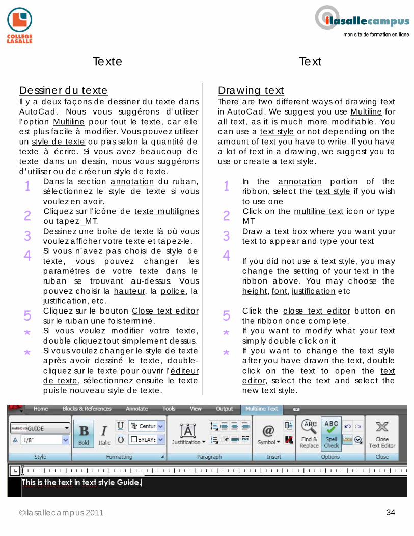
Dessiner du texte Il y a deux façons de dessiner du texte dans AutoCad. Nous vous suggérons d’utiliser l’option Multiline pour tout le texte, car elle est plus facile à modifier. Vous pouvez utiliser un style de texte ou pas selon la quantité de texte à écrire. Si vous avez beaucoup de texte dans un dessin, nous vous suggérons d’utiliser ou de créer un style de texte.
Drawing text There are two different ways of drawing text in AutoCad. We suggest you use Multiline for all text, as it is much more modifiable. You can use a text style or not depending on the amount of text you have to write. If you have a lot of text in a drawing, we suggest you to use or create a text style.
1 Dans la section annotation du ruban, sélectionnez le style de texte si vous voulez en avoir.
1 In the annotation portion of the ribbon, select the text style if you wish to use one
2 Cliquez sur l’icône de texte multilignes ou tapez _MT.
2 Click on the multiline text icon or type MT
3 Dessinez une boîte de texte là où vous voulez afficher votre texte et tapez-le.
3 Draw a text box where you want your text to appear and type your text
4 Si vous n’avez pas choisi de style de texte, vous pouvez changer les paramètres de votre texte dans le ruban se trouvant au-dessus. Vous pouvez choisir la hauteur, la police, la justification, etc.
4 If you did not use a text style, you may change the setting of your text in the ribbon above. You may choose the height, font, justification etc
5 Cliquez sur le bouton Close text editor sur le ruban une fois terminé.
5 Click the close text editor button on the ribbon once complete.
* Si vous voulez modifier votre texte, double cliquez tout simplement dessus.
* If you want to modify what your text simply double click on it
* Si vous voulez changer le style de texte après avoir dessiné le texte, double-cliquez sur le texte pour ouvrir l’éditeur de texte, sélectionnez ensuite le texte puis le nouveau style de texte.
* If you want to change the text style after you have drawn the text, double click on the text to open the text editor, select the text and select the new text style.
©ilasallecampus 2011
35
35
Texte Text
Choisir un style de texte Pour choisir un style de texte, il faut comprendre les principes de dessin dans AutoCad. Veuillez lire la section CHOISIR UN STYLE DE COTE de ce guide. Le texte que vous écrivez dans un dessin doit être le même que celui des styles de cote. (police, grandeur, etc.) Pour déterminer le style de texte dont vous avez besoin, il faut, à priori, déterminer l’échelle à laquelle vous voulez imprimer votre dessin. Une fois celle-ci définie, vous pouvez choisir le style de texte à partir du fichier tex_dim_styles.DWG fourni.
Choosing text styles To choose a style, you must understand the principals of drawing in AutoCad. Please see the CHOOSING A DIMENSION STYLE portion of this guide. The text you write on a drawing must be the same text as is in the dimensions. (font, size etc.) To determine the text style you need, you must first determine the scale that you will be printing your drawing at. Once this is determined, you may choose your text style from the tex_dim_styles.DWG provided.
©ilasallecampus 2011
36
36
Texte Text
Importer un style de texte Chez ilasalle, on vous a fourni un fichier nommé tex_dim_styles.DWG. Dans celui-ci, vous trouverez tous les styles de texte impériaux standards.
Importing text styles At ilasalle you have been provided with a file named tex_dim_styles.DWG. In this file, you will find all the standard imperial text styles.
1 Ouvrez le fichier dans lequel vous voulez importer le style et ouvrez le Design center en tapant _ADCENTER ou en cliquant sur l’icône correspondante.
1 Open the DWG file you wish to import the style to and open the design center by typing ADCENTER or clicking on the icon
2 Sélectionnez l’onglet dossiers en haut de la fenêtre et cherchez le fichier tex_dim_styles.DWG, ou un autre fichier à partir duquel vous voulez importer les styles.
2 Select the folders tab at the top of the window and search for the tex_dim_style.DWG file or another file you wish to import the styles from
3 Une fois que vous avez sélectionné le fichier DWG, cliquez sur le signe + à côté des styles de texte.
3 Once you have the DWG file selected, click on the + beside the text styles
4 Sur le côté droit de la fenêtre, choisissez le style que vous voulez importer et glissez-le dans votre espace objet.
4 Choose the style you wish to import on the right side of the window and drag it into your model space
Si vous importez vos styles de cote à partir du fichier fourni, les styles de texte y seront aussi inclus. Les styles de cote utilisent des styles de texte pour les paramètres de leur texte. Les styles de texte sont nommés avec l’échelle à laquelle ils devraient être imprimés (par exemple, TEX1-4 DIM1-4 est pour l’échelle de 1/4"=1’-0”)
If you import the dimension styles from the file provided, the text styles are inserted as well. Dimension styles use text styles for the parameters of their text. The text styles are named with the scale they should be printed at. (Example : TEX1-4 is for printing at 1/4"=1’-0”)
©ilasallecampus 2011
37
37
Texte Text
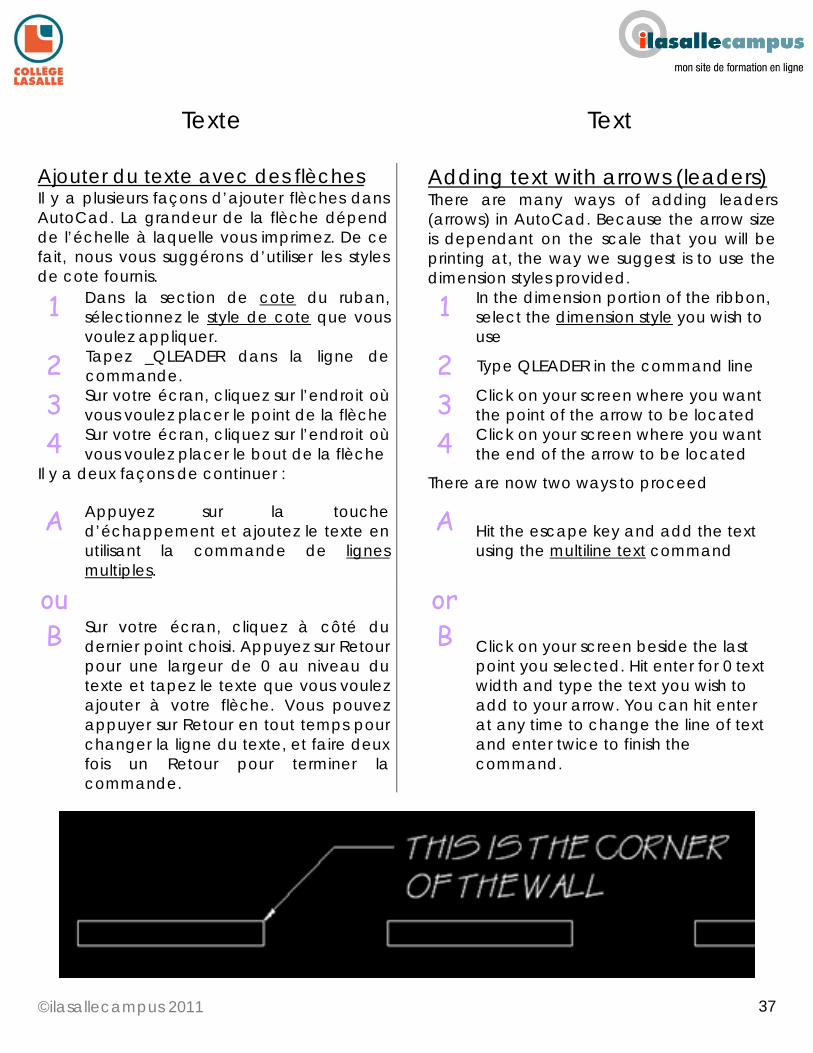
Ajouter du texte avec des flèches Il y a plusieurs façons d’ajouter flèches dans AutoCad. La grandeur de la flèche dépend de l’échelle à laquelle vous imprimez. De ce fait, nous vous suggérons d’utiliser les styles de cote fournis.
Adding text with arrows (leaders) There are many ways of adding leaders (arrows) in AutoCad. Because the arrow size is dependant on the scale that you will be printing at, the way we suggest is to use the dimension styles provided.
1 Dans la section de cote du ruban, sélectionnez le style de cote que vous voulez appliquer.
1 In the dimension portion of the ribbon, select the dimension style you wish to use
2 Tapez _QLEADER dans la ligne de commande.
2 Type QLEADER in the command line
3 Sur votre écran, cliquez sur l’endroit où vous voulez placer le point de la flèche
3 Click on your screen where you want the point of the arrow to be located
4 Sur votre écran, cliquez sur l’endroit où vous voulez placer le bout de la flèche
4 Click on your screen where you want the end of the arrow to be located
Il y a deux façons de continuer :
There are now two ways to proceed
A Appuyez sur la touche d’échappement et ajoutez le texte en utilisant la commande de lignes multiples.
A Hit the escape key and add the text using the multiline text command
ou or
B Sur votre écran, cliquez à côté du dernier point choisi. Appuyez sur Retour pour une largeur de 0 au niveau du texte et tapez le texte que vous voulez ajouter à votre flèche. Vous pouvez appuyer sur Retour en tout temps pour changer la ligne du texte, et faire deux fois un Retour pour terminer la commande.
B Click on your screen beside the last point you selected. Hit enter for 0 text width and type the text you wish to add to your arrow. You can hit enter at any time to change the line of text and enter twice to finish the command.

©ilasallecampus 2011
38
38
Texte Text
Créer un style de texte Les styles de texte sont créés et utilisés pour standardiser tous les textes d’un projet.
Creating a text style Text styles are created and used to standardise all the text draw in a project.
1 Tapez STYLE ou cliquez sur l’icône de style de texte.
1 Type STYLE or click on the text style icon
2 Cliquez sur le bouton new et nommez votre style de texte. de
2 Click on the new button and name your text style
3 Changez les paramètres de votre texte (la police et le style).
3 Change the parameters of your text. The font and style
4 Sélectionnez la hauteur de votre texte. Gardez en tête que la hauteur du texte dépend de l’échelle à laquelle vous allez imprimer. Les standards de dessin indiquent que le texte devrait être entre une hauteur de 1/8” et 1/4". Mais, une hauteur de 1/8” pour le texte, serait seulement applicable quand on imprime à une échelle de 1:1 ou 1’-0”=1’-0”. Veuillez consulter la section sur les échelles de ce guide pour connaître les valeurs des différentes échelles.
4 Select the height of your text. Keep in mind that the height of the text is dependant on what scale you will be printing it at. Drafting standards dictate that text should be between 1/8” and 1/4" in height but giving the text a height of 1/8” would only be applicable when printing at 1:1 or 1’-0”=1’-0”. Please see the scaling part of this guide for the values for different scales.
5 Cliquez sur appliquer et fermer. 5 Click on apply and then close
©ilasallecampus 2011
39
39
Échelle Scale
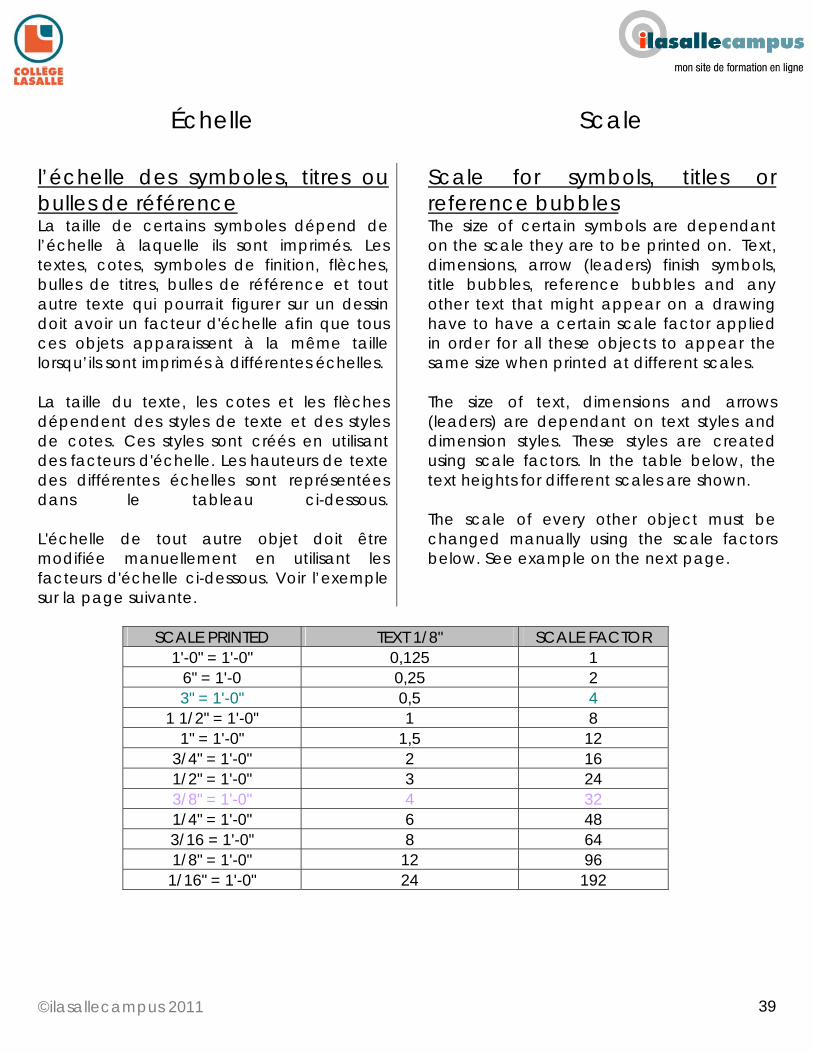
l’échelle des symboles, titres ou bulles de référence La taille de certains symboles dépend de l’échelle à laquelle ils sont imprimés. Les textes, cotes, symboles de finition, flèches, bulles de titres, bulles de référence et tout autre texte qui pourrait figurer sur un dessin doit avoir un facteur d'échelle afin que tous ces objets apparaissent à la même taille lorsqu’ils sont imprimés à différentes échelles. La taille du texte, les cotes et les flèches dépendent des styles de texte et des styles de cotes. Ces styles sont créés en utilisant des facteurs d'échelle. Les hauteurs de texte des différentes échelles sont représentées dans le tableau ci-dessous. L'échelle de tout autre objet doit être modifiée manuellement en utilisant les facteurs d'échelle ci-dessous. Voir l’exemple sur la page suivante.
Scale for symbols, titles or reference bubbles The size of certain symbols are dependant on the scale they are to be printed on. Text, dimensions, arrow (leaders) finish symbols, title bubbles, reference bubbles and any other text that might appear on a drawing have to have a certain scale factor applied in order for all these objects to appear the same size when printed at different scales. The size of text, dimensions and arrows (leaders) are dependant on text styles and dimension styles. These styles are created using scale factors. In the table below, the text heights for different scales are shown. The scale of every other object must be changed manually using the scale factors below. See example on the next page.
SCALE PRINTED TEXT 1/8" SCALE FACTOR
1'-0" = 1'-0" 0,125 1 6" = 1'-0 0,25 2 3" = 1'-0" 0,5 4
1 1/2" = 1'-0" 1 8 1" = 1'-0" 1,5 12
3/4" = 1'-0" 2 16 1/2" = 1'-0" 3 24 3/8" = 1'-0" 4 32 1/4" = 1'-0" 6 48 3/16 = 1'-0" 8 64 1/8" = 1'-0" 12 96 1/16" = 1'-0" 24 192
©ilasallecampus 2011
40
40
Échelle Scale
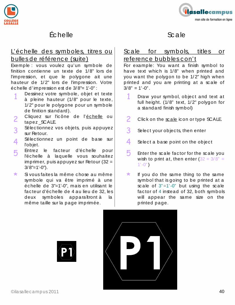
L’échelle des symboles, titres ou bulles de référence (suite) Exemple : vous voulez qu’un symbole de finition contienne un texte de 1/8" lors de l'impression, et que le polygone ait une hauteur de 1/2" lors de l'impression. Votre échelle d’impression est de 3/8"= 1'-0" :
Scale for symbols, titles or reference bubbles con’t For example: You want a finish symbol to have text which is 1/8” when printed and you want the polygon to be 1/2" high when printed and you are printing at a scale of 3/8” = 1’-0”.
1 Dessinez votre symbole, objet et texte à pleine hauteur (1/8" pour le texte, 1/2" pour le polygone pour un symbole de finition standard).
1 Draw your symbol, object and text at full height. (1/8” text, 1/2" polygon for a standard finish symbol)
2 Cliquez sur l'icône de l’échelle ou tapez _SCALE.
2 Click on the scale icon or type SCALE.
3 Sélectionnez vos objets, puis appuyez sur Retour.
3 Select your objects, then enter
4 Sélectionnez un point de base sur l'objet.
4 Select a base point on the object
5 Entrez le facteur d'échelle pour l'échelle à laquelle vous souhaitez imprimer, puis appuyez sur Retour (32 = 3/8"=1'-0").
5 Enter the scale factor for the scale you wish to print at, then enter (32 = 3/8” = 1’-0”)
* Si vous faites la même chose au même symbole qui va être imprimé à une échelle de 3"=1'-0", mais en utilisant le facteur d'échelle de 4 au lieu de 32, les deux symboles apparaîtront à la même taille sur la page imprimée.
* If you do the same thing to the same symbol that is going to be printed at a scale of 3”=1’-0” but using the scale factor of 4 instead of 32, both symbols will appear the same size on the printed page.
©ilasallecampus 2011
41
41
Échelle Scale
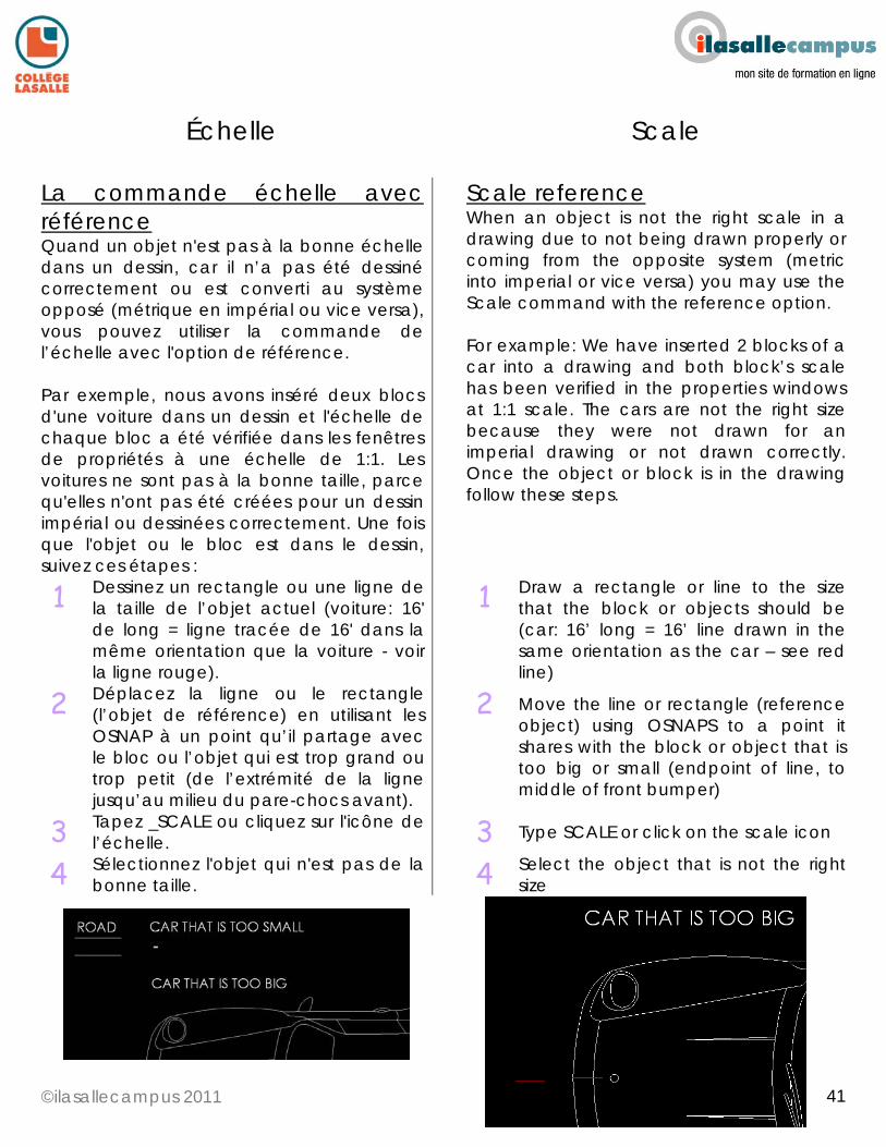
La commande échelle avec référence Quand un objet n'est pas à la bonne échelle dans un dessin, car il n’a pas été dessiné correctement ou est converti au système opposé (métrique en impérial ou vice versa), vous pouvez utiliser la commande de l’échelle avec l'option de référence. Par exemple, nous avons inséré deux blocs d'une voiture dans un dessin et l'échelle de chaque bloc a été vérifiée dans les fenêtres de propriétés à une échelle de 1:1. Les voitures ne sont pas à la bonne taille, parce qu'elles n'ont pas été créées pour un dessin impérial ou dessinées correctement. Une fois que l'objet ou le bloc est dans le dessin, suivez ces étapes :
Scale reference When an object is not the right scale in a drawing due to not being drawn properly or coming from the opposite system (metric into imperial or vice versa) you may use the Scale command with the reference option. For example: We have inserted 2 blocks of a car into a drawing and both block’s scale has been verified in the properties windows at 1:1 scale. The cars are not the right size because they were not drawn for an imperial drawing or not drawn correctly. Once the object or block is in the drawing follow these steps.
1 Dessinez un rectangle ou une ligne de la taille de l’objet actuel (voiture: 16' de long = ligne tracée de 16' dans la même orientation que la voiture - voir la ligne rouge).
1 Draw a rectangle or line to the size that the block or objects should be (car: 16’ long = 16’ line drawn in the same orientation as the car – see red line)
2 Déplacez la ligne ou le rectangle (l’objet de référence) en utilisant les OSNAP à un point qu’il partage avec le bloc ou l’objet qui est trop grand ou trop petit (de l’extrémité de la ligne jusqu’au milieu du pare-chocs avant).
2 Move the line or rectangle (reference object) using OSNAPS to a point it shares with the block or object that is too big or small (endpoint of line, to middle of front bumper)
3 Tapez _SCALE ou cliquez sur l'icône de l’échelle.
3 Type SCALE or click on the scale icon
4 Sélectionnez l'objet qui n'est pas de la bonne taille.
4 Select the object that is not the right size
©ilasallecampus 2011
42
42
Échelle Scale
La commande échelle avec références (suite)
Scale reference con’t
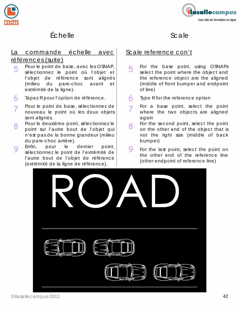
5 Pour le point de base, avec les OSNAP, sélectionnez le point où l’objet et l’objet de référence sont alignés (milieu du pare-choc avant et extrémité de la ligne).
5 For the base point, using OSNAPs select the point where the object and the reference object are the aligned (middle of front bumper and endpoint of line)
6 Tapez R pour l’option de référence. 6 Type R for the reference option
7 Pour le point de base, sélectionnez de nouveau le point où les deux objets sont alignés.
7 For a base point, select the point where the two objects are aligned again
8 Pour le deuxième point, sélectionnez le point sur l’autre bout de l’objet qui n’est pas de la bonne grandeur (milieu du pare-choc arrière).
8 For the second point, select the point on the other end of the object that is not the right size (middle of back bumper)
9 Enfin, pour le dernier point, sélectionnez le point de l’extrémité de l’autre bout de l’objet de référence (extrémité de la ligne de référence).
9 For the last point, select the point on the other end of the reference line (other endpoint of reference line)
©ilasallecampus 2011
43
43
Épaisseur des lignes Lineweights
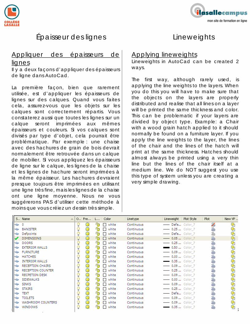
Appliquer des épaisseurs de lignes Il y a deux façons d’appliquer des épaisseurs de ligne dans AutoCad. La première façon, bien que rarement utilisée, est d’appliquer les épaisseurs de lignes sur des calques. Quand vous faites cela, assurez-vous que les objets sur les calques sont correctement répartis. Vous constaterez aussi que toutes les lignes sur un calque seront imprimées aux mêmes épaisseurs et couleurs. Si vos calques sont divisés par type d’objet, cela pourrait être problématique. Par exemple : une chaise avec des hachures de grain de bois devrait normalement être retrouvée dans un calque de mobilier. Si vous appliquez les épaisseurs de ligne sur le calque, les lignes de la chaise et les lignes de hachure seront imprimées à la même épaisseur. Les hachures devraient presque toujours être imprimées en utilisant une ligne très fine, mais les lignes de la chaise ont une ligne moyenne. Nous ne vous suggérerons PAS d’utiliser cette méthode à moins que vous créiez un dessin très simple.
Applying lineweights Lineweights in AutoCad can be created 2 ways. The first way, although rarely used, is applying the line weights to the layers. When you do this you will have to make sure that the objects on the layers are properly distributed and realise that all lines on a layer will be printed the same thickness and color. This can be problematic if your layers are divided by object type. Example: a Chair with a wood grain hatch applied to it should normally be found on a furniture layer. If you apply the line weights to the layer, the lines of the chair and the lines of the hatch will print at the same thickness. Hatches should almost always be printed using a very thin line but the lines of the chair itself at a medium line. We do NOT suggest you use this type of system unless you are creating a very simple drawing.
©ilasallecampus 2011
44
44
Épaisseur de lignes Lineweights
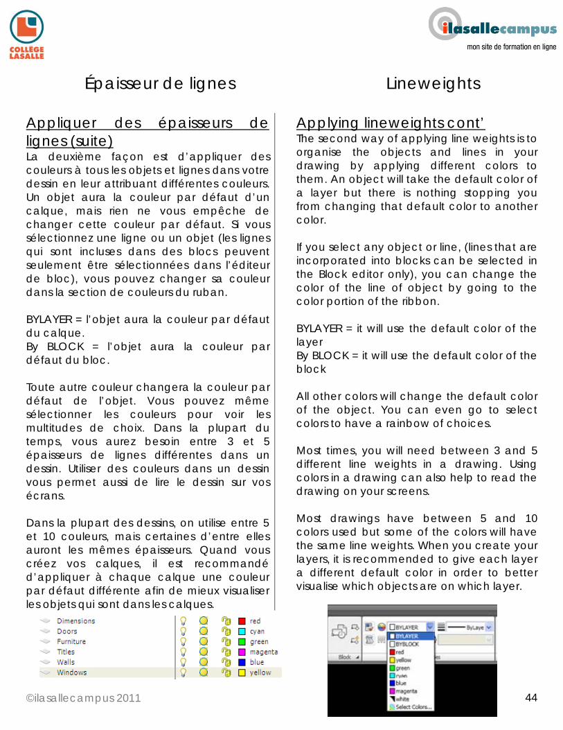
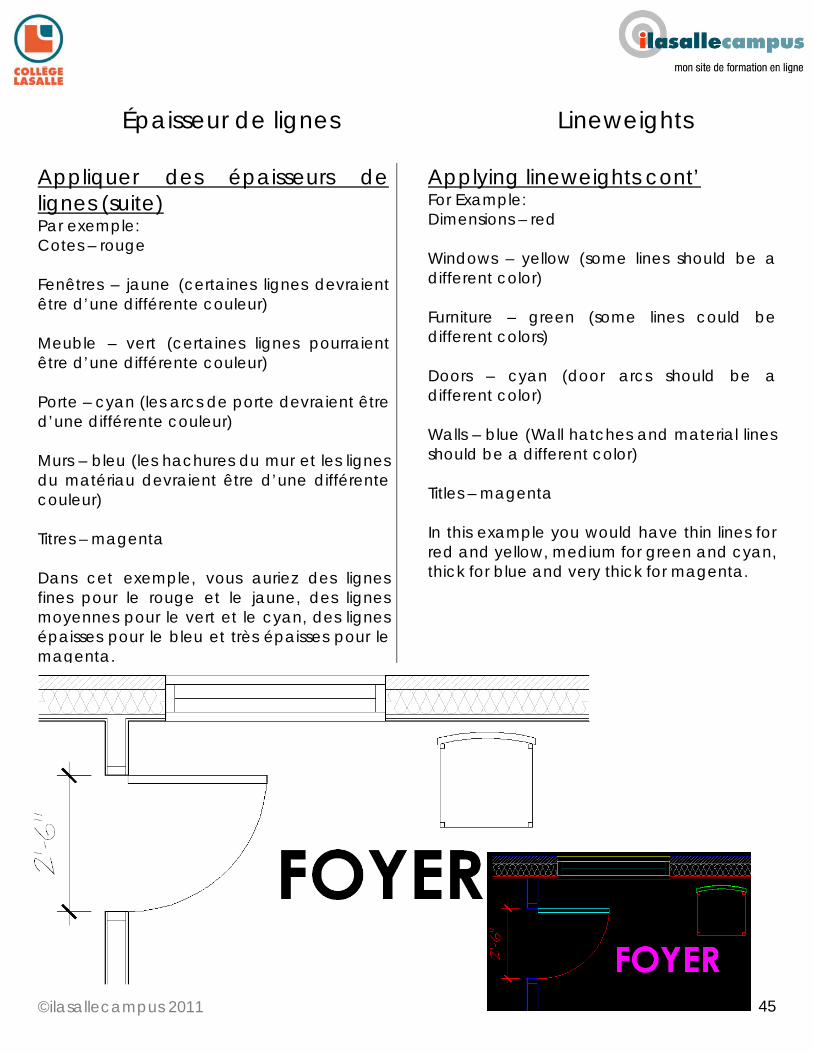
Appliquer des épaisseurs de lignes (suite) La deuxième façon est d’appliquer des couleurs à tous les objets et lignes dans votre dessin en leur attribuant différentes couleurs. Un objet aura la couleur par défaut d’un calque, mais rien ne vous empêche de changer cette couleur par défaut. Si vous sélectionnez une ligne ou un objet (les lignes qui sont incluses dans des blocs peuvent seulement être sélectionnées dans l’éditeur de bloc), vous pouvez changer sa couleur dans la section de couleurs du ruban. BYLAYER = l’objet aura la couleur par défaut du calque. By BLOCK = l’objet aura la couleur par défaut du bloc. Toute autre couleur changera la couleur par défaut de l’objet. Vous pouvez même sélectionner les couleurs pour voir les multitudes de choix. Dans la plupart du temps, vous aurez besoin entre 3 et 5 épaisseurs de lignes différentes dans un dessin. Utiliser des couleurs dans un dessin vous permet aussi de lire le dessin sur vos écrans. Dans la plupart des dessins, on utilise entre 5 et 10 couleurs, mais certaines d’entre elles auront les mêmes épaisseurs. Quand vous créez vos calques, il est recommandé d’appliquer à chaque calque une couleur par défaut différente afin de mieux visualiser les objets qui sont dans les calques.
Applying lineweights cont’ The second way of applying line weights is to organise the objects and lines in your drawing by applying different colors to them. An object will take the default color of a layer but there is nothing stopping you from changing that default color to another color. If you select any object or line, (lines that are incorporated into blocks can be selected in the Block editor only), you can change the color of the line of object by going to the color portion of the ribbon. BYLAYER = it will use the default color of the layer By BLOCK = it will use the default color of the block All other colors will change the default color of the object. You can even go to select colors to have a rainbow of choices. Most times, you will need between 3 and 5 different line weights in a drawing. Using colors in a drawing can also help to read the drawing on your screens. Most drawings have between 5 and 10 colors used but some of the colors will have the same line weights. When you create your layers, it is recommended to give each layer a different default color in order to better visualise which objects are on which layer.
©ilasallecampus 2011
45
45
Épaisseur de lignes Lineweights
Appliquer des épaisseurs de lignes (suite) Par exemple: Cotes – rouge Fenêtres – jaune (certaines lignes devraient être d’une différente couleur) Meuble – vert (certaines lignes pourraient être d’une différente couleur) Porte – cyan (les arcs de porte devraient être d’une différente couleur) Murs – bleu (les hachures du mur et les lignes du matériau devraient être d’une différente couleur) Titres – magenta Dans cet exemple, vous auriez des lignes fines pour le rouge et le jaune, des lignes moyennes pour le vert et le cyan, des lignes épaisses pour le bleu et très épaisses pour le magenta.
Applying lineweights cont’ For Example: Dimensions – red Windows – yellow (some lines should be a different color) Furniture – green (some lines could be different colors) Doors – cyan (door arcs should be a different color) Walls – blue (Wall hatches and material lines should be a different color) Titles – magenta In this example you would have thin lines for red and yellow, medium for green and cyan, thick for blue and very thick for magenta.
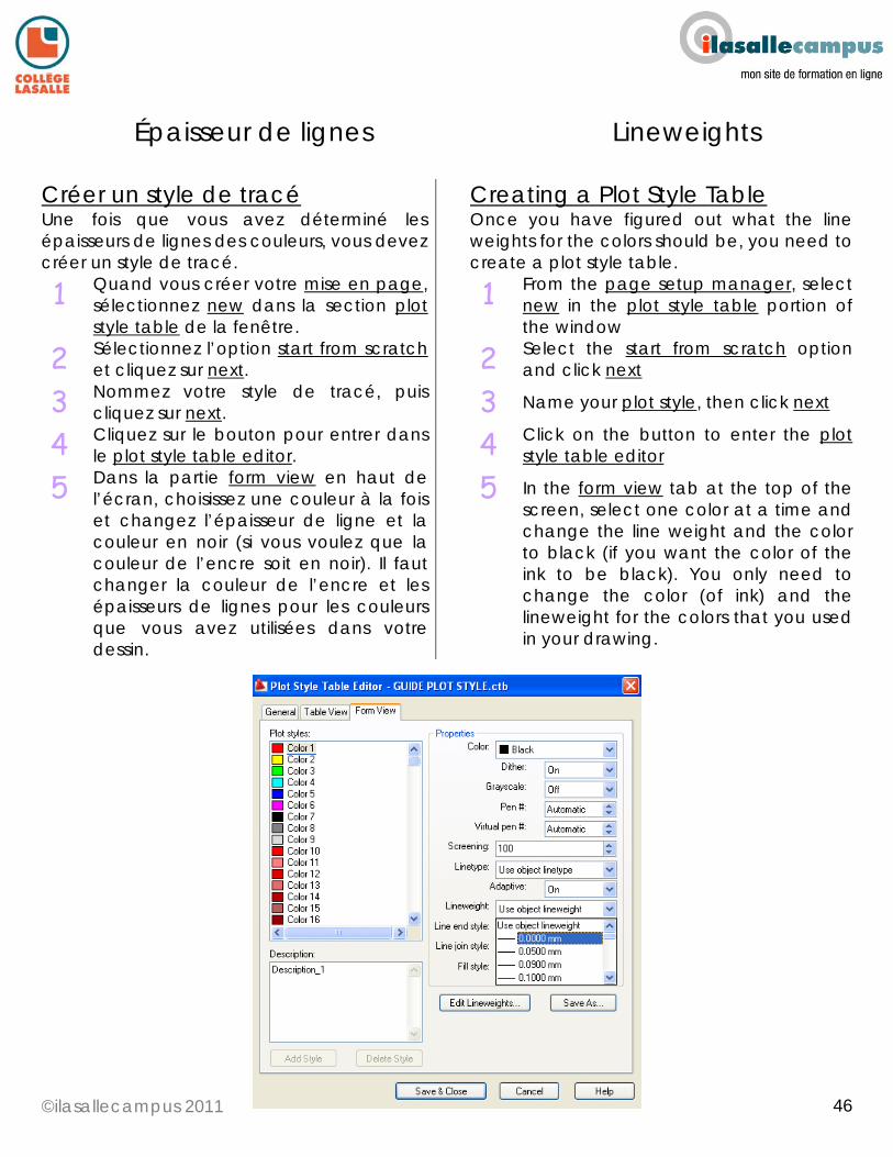
©ilasallecampus 2011
46
46
Épaisseur de lignes Lineweights
Créer un style de tracé Une fois que vous avez déterminé les épaisseurs de lignes des couleurs, vous devez créer un style de tracé.
Creating a Plot Style Table Once you have figured out what the line weights for the colors should be, you need to create a plot style table.
1 Quand vous créer votre mise en page, sélectionnez new dans la section plot style table de la fenêtre.
1 From the page setup manager, select new in the plot style table portion of the window
2 Sélectionnez l’option start from scratch et cliquez sur next.
2 Select the start from scratch option and click next
3 Nommez votre style de tracé, puis cliquez sur next.
3 Name your plot style, then click next
4 Cliquez sur le bouton pour entrer dans le plot style table editor.
4 Click on the button to enter the plot style table editor
5 Dans la partie form view en haut de l’écran, choisissez une couleur à la fois et changez l’épaisseur de ligne et la couleur en noir (si vous voulez que la couleur de l’encre soit en noir). Il faut changer la couleur de l’encre et les épaisseurs de lignes pour les couleurs que vous avez utilisées dans votre dessin.
5 In the form view tab at the top of the screen, select one color at a time and change the line weight and the color to black (if you want the color of the ink to be black). You only need to change the color (of ink) and the lineweight for the colors that you used in your drawing.
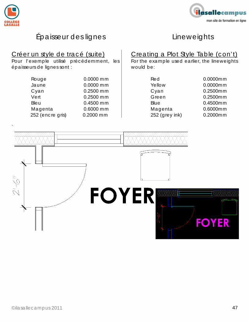
©ilasallecampus 2011
47
47
Épaisseur des lignes Lineweights
Créer un style de tracé (suite) Pour l’exemple utilisé précédemment, les épaisseurs de lignes sont :
Rouge 0.0000 mm Jaune 0.0000 mm Cyan 0.2500 mm Vert 0.2500 mm Bleu 0.4500 mm Magenta 0.6000 mm
252 (encre gris) 0.2000 mm
Creating a Plot Style Table (con’t) For the example used earlier, the lineweights would be:
Red 0.0000mm Yellow 0.0000mm Cyan 0.2500mm Green 0.2500mm Blue 0.4500mm Magenta 0.6000mm 252 (grey ink) 0.2000mm
`
©ilasallecampus 2011
48
48
Épaisseur de lignes Lineweights
Utiliser un style de tracé Une fois que vous avez créé un style de tracé, vous pouvez utiliser le même fichier pour tous les dessins du moment que vous continuez à utiliser les mêmes couleurs pour vos objets. Une fois que votre dessin est terminé et que les paramètres de votre page et mise en page sont réglés, choisissez tout simplement le style de tracé dans le menu déroulant dans la fenêtre de la mise en page. Votre style de tracé n’est pas attaché à votre fichier AutoCad comme les styles de cote ou style de texte. Ce fichier est seulement sur votre ordinateur. Si vous décidez d’envoyer votre dessin à un entrepreneur ou architecte, vous devez aussi leur envoyer votre STYLE DE TRACÉ (fichier .CTB). Pour le trouver dans votre ordinateur, il suffit de suivre les étapes suivantes :
Using a Plot Style Table Once you have created a plot style table you may reuse this same file for all of your drawings as long as you continue to use the same colors for your objects. Once your drawing is completed, your page setup and layout are set, you simply choose this plot style table from the drop down menu in the page setup window. The plot style table is not attached to your autocad file like a dimension or text style. This file is only on your computer. If you decided to send your drawing to a contactor or architect, you must remember to send them your PLOT STYLE TABLE (.CTB file )as well. To find this file, you must follow these steps:
1 Tapez _OPTIONS dans la ligne de commandes.
1 Type OPTIONS in your command line
2 Cliquez sur l’onglet files. 2 Click on the files tab
3 Cliquez sur le signe + à côté de printer support file path
3 Click on the + beside printer support file path
4 Cliquez sur le signe + à côté plot style table search path, et vous aurez l’emplacement sur votre disque dur. Écrivez les informations sur une feuille (vous ne verrez pas cette fenêtre dans les étapes suivantes).
4 Click on the + beside plot style table search path and this will give you the location on your hard drive of where the file is saved. Write this down on a piece of paper.
5 Dans les paramètres de votre système d’exploitation (Windows), vous devez changer les paramètres de vos dossiers pour afficher les fichiers et dossiers cachés. Si vous ne faites pas cette étape, quand vous suivrez les chemins indiqués par la fenêtre d’option, vous ne serez pas en mesure de voir le fichier, puisqu’il se trouve dans un dossier caché.
5 In the setting of your operating system (windows) you must change your folder setting in order to display hidden files and folders. If you do not do this step, when you follow the path given by the options window you will end up at a dead end since there are folders in the path that are hidden.
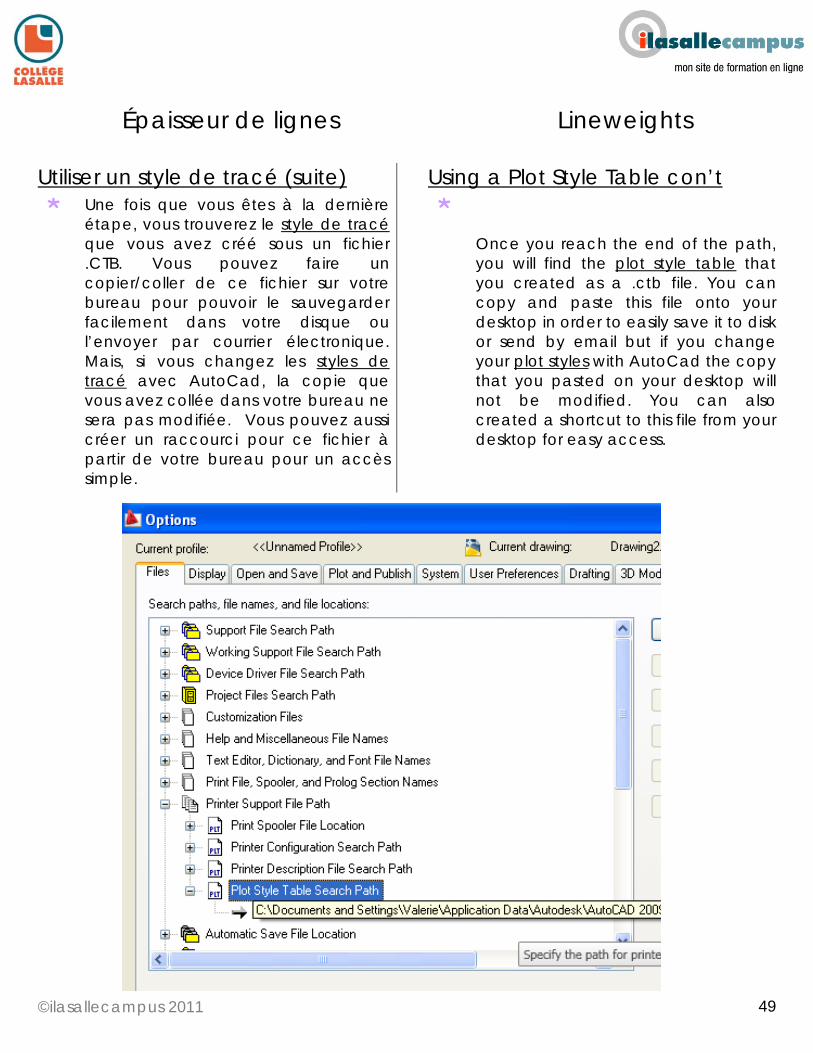
©ilasallecampus 2011
49
49
Épaisseur de lignes Lineweights
Utiliser un style de tracé (suite) Using a Plot Style Table con’t
* Une fois que vous êtes à la dernière étape, vous trouverez le style de tracé que vous avez créé sous un fichier .CTB. Vous pouvez faire un copier/coller de ce fichier sur votre bureau pour pouvoir le sauvegarder facilement dans votre disque ou l’envoyer par courrier électronique. Mais, si vous changez les styles de tracé avec AutoCad, la copie que vous avez collée dans votre bureau ne sera pas modifiée. Vous pouvez aussi créer un raccourci pour ce fichier à partir de votre bureau pour un accès simple.
* Once you reach the end of the path, you will find the plot style table that you created as a .ctb file. You can copy and paste this file onto your desktop in order to easily save it to disk or send by email but if you change your plot styles with AutoCad the copy that you pasted on your desktop will not be modified. You can also created a shortcut to this file from your desktop for easy access.
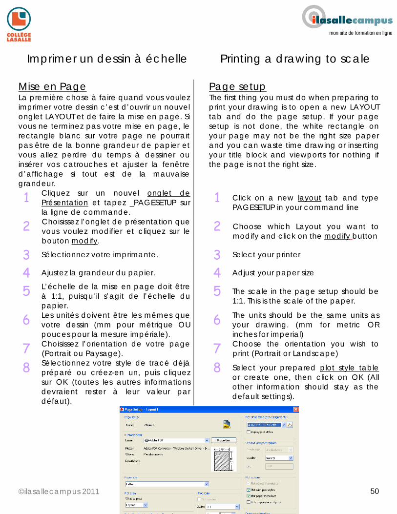
©ilasallecampus 2011
50
50
Imprimer un dessin à échelle Printing a drawing to scale
Mise en Page La première chose à faire quand vous voulez imprimer votre dessin c’est d’ouvrir un nouvel onglet LAYOUT et de faire la mise en page. Si vous ne terminez pas votre mise en page, le rectangle blanc sur votre page ne pourrait pas être de la bonne grandeur de papier et vous allez perdre du temps à dessiner ou insérer vos catrouches et ajuster la fenêtre d’affichage si tout est de la mauvaise grandeur.
Page setup The first thing you must do when preparing to print your drawing is to open a new LAYOUT tab and do the page setup. If your page setup is not done, the white rectangle on your page may not be the right size paper and you can waste time drawing or inserting your title block and viewports for nothing if the page is not the right size.
1 Cliquez sur un nouvel onglet de Présentation et tapez _PAGESETUP sur la ligne de commande.
1 Click on a new layout tab and type PAGESETUP in your command line
2 Choisissez l’onglet de présentation que vous voulez modifier et cliquez sur le bouton modify.
2 Choose which Layout you want to modify and click on the modify button
3 Sélectionnez votre imprimante. 3 Select your printer
4 Ajustez la grandeur du papier. 4 Adjust your paper size
5 L’échelle de la mise en page doit être à 1:1, puisqu’il s’agit de l’échelle du papier.
5 The scale in the page setup should be 1:1. This is the scale of the paper.
6 Les unités doivent être les mêmes que votre dessin (mm pour métrique OU pouces pour la mesure impériale).
6 The units should be the same units as your drawing. (mm for metric OR inches for imperial)
7 Choisissez l’orientation de votre page (Portrait ou Paysage).
7 Choose the orientation you wish to print (Portrait or Landscape)
8 Sélectionnez votre style de tracé déjà préparé ou créez-en un, puis cliquez sur OK (toutes les autres informations devraient rester à leur valeur par défaut).
8 Select your prepared plot style table or create one, then click on OK (All other information should stay as the default settings).
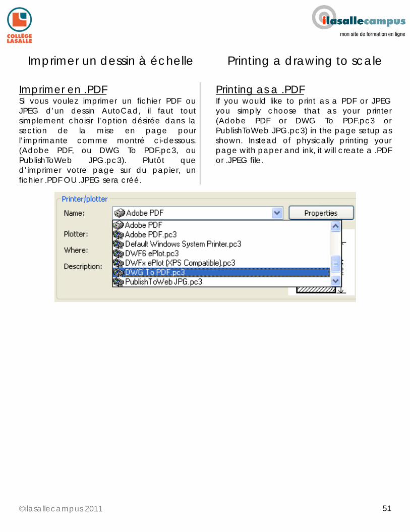
©ilasallecampus 2011
51
51
Imprimer un dessin à échelle Printing a drawing to scale
Imprimer en .PDF Si vous voulez imprimer un fichier PDF ou JPEG d’un dessin AutoCad, il faut tout simplement choisir l’option désirée dans la section de la mise en page pour l’imprimante comme montré ci-dessous. (Adobe PDF, ou DWG To PDF.pc3, ou PublishToWeb JPG.pc3). Plutôt que d’imprimer votre page sur du papier, un fichier .PDF OU .JPEG sera créé.
Printing as a .PDF If you would like to print as a PDF or JPEG you simply choose that as your printer (Adobe PDF or DWG To PDF.pc3 or PublishToWeb JPG.pc3) in the page setup as shown. Instead of physically printing your page with paper and ink, it will create a .PDF or .JPEG file.
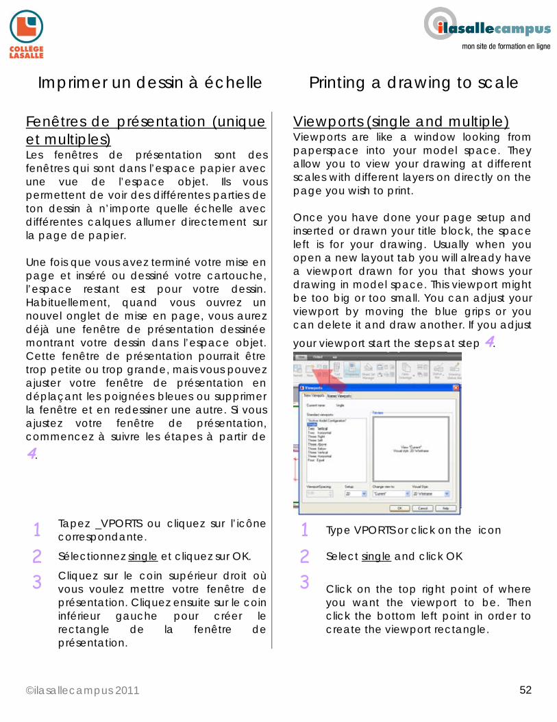
©ilasallecampus 2011
52
52
Imprimer un dessin à échelle Printing a drawing to scale
Fenêtres de présentation (unique et multiples) Les fenêtres de présentation sont des fenêtres qui sont dans l’espace papier avec une vue de l’espace objet. Ils vous permettent de voir des différentes parties de ton dessin à n’importe quelle échelle avec différentes calques allumer directement sur la page de papier. Une fois que vous avez terminé votre mise en page et inséré ou dessiné votre cartouche, l’espace restant est pour votre dessin. Habituellement, quand vous ouvrez un nouvel onglet de mise en page, vous aurez déjà une fenêtre de présentation dessinée montrant votre dessin dans l’espace objet. Cette fenêtre de présentation pourrait être trop petite ou trop grande, mais vous pouvez ajuster votre fenêtre de présentation en déplaçant les poignées bleues ou supprimer la fenêtre et en redessiner une autre. Si vous ajustez votre fenêtre de présentation, commencez à suivre les étapes à partir de 4.
Viewports (single and multiple) Viewports are like a window looking from paperspace into your model space. They allow you to view your drawing at different scales with different layers on directly on the page you wish to print. Once you have done your page setup and inserted or drawn your title block, the space left is for your drawing. Usually when you open a new layout tab you will already have a viewport drawn for you that shows your drawing in model space. This viewport might be too big or too small. You can adjust your viewport by moving the blue grips or you can delete it and draw another. If you adjust your viewport start the steps at step 4.
1 Tapez _VPORTS ou cliquez sur l’icône correspondante.
1 Type VPORTS or click on the icon
2 Sélectionnez single et cliquez sur OK. 2 Select single and click OK
3 Cliquez sur le coin supérieur droit où vous voulez mettre votre fenêtre de présentation. Cliquez ensuite sur le coin inférieur gauche pour créer le rectangle de la fenêtre de présentation.
3 Click on the top right point of where you want the viewport to be. Then click the bottom left point in order to create the viewport rectangle.
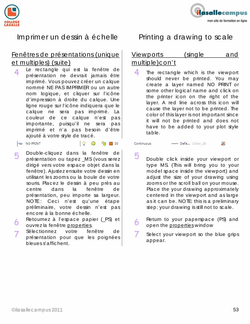
©ilasallecampus 2011
53
53
Imprimer un dessin à échelle Printing a drawing to scale
Fenêtres de présentations (unique et multiples) (suite)
Viewports (single and multiple)con’t
4 Le rectangle qui est la fenêtre de présentation ne devrait jamais être imprimé. Vous pouvez créer un calque nommé NE PAS IMPRIMER ou un autre nom logique, et cliquer sur l’icône d’impression à droite du calque. Une ligne rouge sur l’icône indiquera que le calque ne sera pas imprimé. La couleur de ce calque n’est pas importante, puisqu’il ne sera pas imprimé et n’a pas besoin d’être ajouté à votre style de tracé.
4 The rectangle which is the viewport should never be printed. You may create a layer named NO PRINT or some other logical name and click on the printer icon on the right of the layer. A red line across this icon will cause the layer not to be printed. The color of this layer is not important since it will not be printed and does not have to be added to your plot style table.
5 Double-cliquez dans la fenêtre de présentation ou tapez _MS (vous serez dirigé vers votre espace objet dans la fenêtre). Ajustez ensuite votre dessin en utilisant les zooms ou la boule de votre souris. Placez le dessin à peu près au centre dans la fenêtre de présentation, peu importe sa largeur. NOTE : Ceci n’est qu’une étape préliminaire, votre dessin n’est pas encore à la bonne échelle.
5 Double click inside your viewport or type MS. (This will bring you to your model space inside the viewport) and adjust the size of your drawing using zooms or the scroll ball on your mouse. Place the your drawing approximately centered in the viewport and as large as it can be. NOTE: this is a preliminary step: your drawing is still not to scale.
6 Retournez à l’espace papier (_PS) et ouvrez la fenêtre properties.
6 Return to your paperspace (PS) and open the properties window
7 Sélectionnez votre fenêtre de présentation pour que les poignées bleues s’affichent.
7 Select your viewport so the blue grips appear.
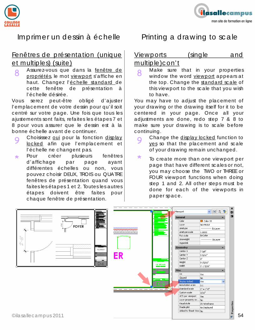
©ilasallecampus 2011
54
54
Imprimer un dessin à échelle Printing a drawing to scale
Fenêtres de présentation (unique et multiples) (suite)
Viewports (single and multiple)con’t
8 Assurez-vous que dans la fenêtre de propriétés, le mot viewport s’affiche en haut. Changez l’échelle standard de cette fenêtre de présentation à l’échelle désirée.
8 Make sure that in your properties window the word viewport appears at the top. Change the standard scale of this viewport to the scale that you wish to have.
Vous serez peut-être obligé d’ajuster l’emplacement de votre dessin pour qu’il soit centré sur votre page. Une fois que tous les ajustements sont faits, refaites les étapes 7 et 8 pour vous assurer que le dessin est à la bonne échelle avant de continuer.
You may have to adjust the placement of your drawing or the drawing itself for it to be centered in your page. Once all your adjustments are done, redo step 7 & 8 to make sure your drawing is to scale before continuing.
9 Choisissez oui pour la fonction display locked afin que l’emplacement et l’échelle ne changent pas.
9 Change the display locked function to yes so that the placement and scale of your drawing remain unchanged.
* Pour créer plusieurs fenêtres d’affichage par page ayant différentes échelles ou non, vous pouvez choisir DEUX, TROIS ou QUATRE fenêtres de présentation quand vous faites les étapes 1 et 2. Toutes les autres étapes doivent être faites pour chaque fenêtre de présentation.
* To create more than one viewport per page that have different scales or not, you may choose the TWO or THREE or FOUR viewport functions when doing step 1 and 2. All other steps must be done for each of the viewports in paper space.