Embed Size (px)
Citation preview
MONTAGE SUR LA PROUE :Il est recommandé de se faire assister pour cette procédure.1. Pour la pose, ne séparez pas l’arbre/moteur du garde-
proue Bowguard. Le ressort du garde-proue est sous tension et doit toujours rester assuré.
2. 2. Posez le support, le moteur ramené à fond (à plat), sur le pont du bateau :
• Montez le moteur le plus près possible de l’axe du bateau.
• Assurez-vous qu’il n’y a pas d’obstacle au perçage dans la zone de la proue située sous l’emplacement choisi.
• Assurez-vous que le support du moteur est assez loin du bord du bateau. Le moteur ne doit rencontrer aucun obstacle lorsqu’il est abaissé ou remonté.
3. 5. Montez la plaque sur la proue avec les boulons (1/4-20 x 8,89 cm (3-1/2 po)), rondelles et écrous fournis.
REMARQUE : Si possible, serrez tout les jeux de boulons de montage, écrous et rondelles.
4. Installez la bande Velcro entre le moteur et le pont du bateau, entre les deuxième et troisième jeux de trous de montage.
5. Montez la plaque sur la proue par les trous percés au moyen des boulons de 1/4-20 x 8,89 cm (3-1/2 po), écrous et rondelles fournis.
REMARQUE: Si possible, fixez tous les jeux de boulons, écrous et rondelles de montage.
6. Installez le stabilisateur de montant de proue (si compris). Voyez la page 5 pour ses instructions d’installation.
CAUTION: MAKE SURE YOUR MOTOR IS MOUNTED ON A LEVEL SURFACEPRÉCAUTION : ASSUREZ-VOUS QUE LE MOTEUR EST MONTÉ SUR UNE SURFACE DE NIVEAU.
INSTALLATION OF THE BOWMOUNT:We recommend that you have another person help with this
procedure.1. For installation, do not remove the shaft/motor from the
Bowguard. The Bowguard spring is under tension and must always remain secured.
2. Place the mount, with the motor in the fully retracted (flat) position, on the deck of the boat:
• The motor should be mounted as close to the centerline of the boat as possible.
• Make sure bow area under the chosen location is clear and unobstructed for drilling.
• Make sure the motor rest is positioned far enough beyond the edge of the boat. The motor, as it is lowered into the water or raised into the boat, must not encounter any obstructions.
3. Once in position, determine which bolt pattern is to be used (see below), mark at-least 4 of the holes in the bow
plate and drill through with a 9/32” drill bit. Either pattern may be used when installing the motor.
Pattern 1. Minnkota 3” bolt pattern standard motors. Pattern 2. Alternate 4” bolt pattern commonly used.
NOTE: If pattern 2 is to be used, the right side plate must be removed to access the mounting holes in the bow plate.
4. Install Velcro strap between the motor and deck of boat between second and third set of mounting holes.
5. Mount the plate to the bow through the drilled holes using the provided (1/4-20 x 3-1/2”) bolts, nuts and washers.
NOTE: If possible, secure all sets of mounting bolts, nuts and washers.
6. Install the bow mount stabilizer (if included). See page 5 for installation instructions.
Velcro Strapla bande Velcro
Position the Bowmount close to the centerline of the boat and in an area free of obstructions.
Positionnez le support de proue le plus près possible de l’axe du bateau et dans une zone sans obstacles.
INSTA
LLATIO
N
PO
SE
4
796
200
500700
720 721
980
710
815
725730
735
740
745
750
760
765810
715
830
835
820
825
845
860
865870
875
880
940
975
950
955
885
890 910
920915
925
935
930
932
905900895
770775
780
785
790
795
800
850
855
510
515 520525
530
550
555
560
565
575
580
585
590
595
600
605
610
615
620
625
630635
640
535540
545
205
210
212215
220
225
230
235
240245
250255
260
265
270 274
275
280
285290
586
295
300
340
345
350
355
360
365
370
400275
460
455
425
430
435
440 450
445465
470
475
480
485
490
415
420
137
136135
375
385
380390
395
305
310
315
320
325
330
295
715
737
752
751
753
871
711
776
125
30
70
115
120
10
20
5
8565
50
15
35
100
95
90
80
110
71
25
40
41
1010
1000
1015
1020
60
1
570
296
297
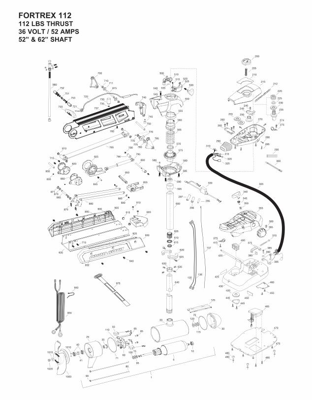
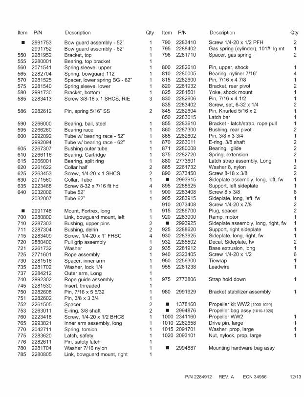
FORTREX 112112 LBS THRUST36 VOLT / 52 AMPS52” & 62” SHAFT
PA
RTS D
IAG
RA
M
* This item is part of an assembly. This item cannot be sold separately due to machining and /or assembly that is required.
PA
RTS LIST
Item P/N Description Qty Item P/N Description Qty 1 2317081 36V Motor 52” FW 1 2327081 36V Motor US2 52” 1 2327082 36V Motor US2 62” 1 5 2-100-245 Armature assembly 1 10 140-014 Bearing 1 15 788-040 Retaining ring 1 20 2-200-240 Center housing assemby 25 2-300-150 Brush end housing assembly 1 30 421-240 Plain end housing assembly STD 1 9421-245 Plain end housing US2 52” 1 9421-246 Plain end housing US2 62” 1 35 144-017 Flange bearing 1 40 880-025 Seal 2 41 725-095 Paper tube - seal bore 1 50 188-095 Brush 2 60 9-738-011 Brush plate assembly 1 65 975-045 Brush spring 2 2881450 Seal & Oring Kit 70 701-098 O-ring, plain end 1 71 701-046 O-ring, brush end 1 80 701-009 O-ring, thru-bolt 2 85 2053410 Screw, 10-32 x 1/2” 2 90 830-094 Thru-bolt 12-24 2 95 990-051 Washer, steel 1 100 990-052 Washer, nylatron 2110 2777312 Ferrite bead w/ shrink 1115 990-011 Washer, shim 1120 992-011 Washer, belleville 2125 582-016 Clip, retaining 1135 640-043 Leadwire, black 52” 1 640-047 Leadwire, black 62” 1 136 640-143 Leadwire, red 52” 1 640-147 Leadwire, red 62” 1 137 640-316 Leadwire, brown 52” 1 640-317 Leadwire, brown 62” 1
200 2990140 Indicator assembly 1205 2282730 Spring, indicator 1210 2285611 Decal, Cover 112#, fw 1 2285612 Decal, Cover 112# US2, fw 1212 2285616 Decal, Control box, fw 2215 2280200 Cover, control box 1220 2232360 Pulley, cable drum 1225 2261730 Washer, nylon 1230 2267800 Gear, indicator 1235 2996247 Top bearing, pinion drive 1240 2301310 Screw 8-18 x 1/2 1245 2261905 Bracket, indicator 1250 2262221 Indicator, drive 1255 2267800 Gear, indicator 2260 2223430 Screw 8 x 3/4 4265 2261901 Bracket, conduit 1270 2282500 Control box 1274 2372100 8-18 x 5/8 1
275 2263201 Clamp, wire harness 2280 2053414 8-32 x 1/2 tri-lobe 3285 2372100 Screw 8-18 x 2/8 4290 2265110 Boot, control box 1295 2355410 Shrik tube 3/8 3296 2335400 Shrink Tube 1/2” OD x 2” 2297 2375400 Shrink Tube 1/4” OD x 1 3/4” 1300 2264015 Light, indicator 1305 2265430 Cable jacket, 5’ 1310 2261220 Wire harness, max 1315 2267505 Cable assembly, right, 5’ 1320 2267515 Cably assembly, left, 5’ 1325 2211410 Cable extension, US2 175” 1330 2218200 Fuse holder assembly 1340 2993705 Push button w/ magnet 1345 2260810 Clip, reed sensor 1350 2302732 Spring, pedal button 1355 2994496 Foot pedal w/ plug 1360 2263000 E-ring, knob 1365 2280115 Knob, speed control VARS 1370 2263466 Screw 1/4-20 x 2 1375 2263210 Bracket, conduit adjustment 1380 2263140 Nylock keeper 1385 2372100 Screw 8-18 x 5/8 2390 2261714 Washer, max foot pedal 2395 2265115 Boot, foot pedal 1400 2254031 Switch, mom/off/con 1415 2332103 Screw 6-20 x 3/8 1420 2260511 Pin, pivot, foot pedal 1425 2266610 Decal, on/off switch 1430 2992104 Foot pedal base 1435 2262301 Pully, foot pedal 1440 2266401 Cover, pulley 1445 2301310 Screw 8-18 x 1/2 2450 2266413 Tension Screw 1455 2332103 Screw 6-20 x 3/8 2460 2266412 Switch plate, foot pedal 1465 2264056 Control board max 24/36 1470 2264511 Bottom plate, max 1475 2372100 Screw 8-18 x 5/8 5480 2223455 Screw 10-32 x 1/2 zp 2485 2265126 Bumper pad, foot pedal 4490 2378600 Pop rivet, 3/16 x 3/4 alum 4
2991550 Clamp collar assembly 1500 2073102 Nut, 1/4-28 ss 1510 2071550 Collar clamp, “A” side 1515 2072621 Pin, knurled 1520 2071718 Washer #10 nylon retaining 1525 2071555 Collar clamp, “B” side 1530 2281505 Knob - Soft grip, FW 1535 2075120 Pad, urethane, depth collar 1540 2283414 Screw 5/16-18 SHCS, RIE 1545 2281700 Washer 5/16 Lock 1
ASSEM
BLY
A
SSEMB
LAG
E
3
ASSEMBLY OF MOTOR TO MOUNT:1. Place the mount on an elevated surface such as a work-
bench or tailgate of pickup. 2. Remove the 5/16” Allen screw and lock washer from the
mount using an Allen wrench. (See picture) 3. Align the key ways on the inside of the bowguard with
the ends links on the mount. Lower the motor assembly straight down until seated.
4. Install the 5/16” Allen screw / lock washer and tighten to 10-12 ft/lbs.
5. Stow the motor into the flat position by pulling the rope/handle to disengage the latch bar, allowing the motor to fold into the flat position.
6. Once in the stowed or flat position, the gas spring pin can be installed. Follow the steps below to install the gas spring pin and spacers:
• Locate the upper gas spring pin and spacers in bag assembly
• Align the end of the gas spring with the holes in the outer arm
• Install pin, spacers and Phillips flat head screws • Tighten screws until the heads are flush with the
outer arm NOTE: Screws have a pre-applied thread locker, DO
NOT apply additional thread locker to screws as that may prevent future removal.
7. Motor / mount can now be installed onto the boat. Proceed to next page for mounting instructions.
ATTENTION: The 5/16” Allen screw must be tight when installed and periodically tightened to 10-12 ft/lbs (Step 4), which will allow the motor to be stowed prop-erly. Tighten the Allen screw when the mount is in the deployed position.
ASSEMBLAGE DU MOTEUR AU MONTANT :
1. Placez le montant sur une surface élevée, un banc de tra-vail ou le hayon d’une camionnette par exemple.
2. Enlevez la vis Allen de 7,93 mm (5/16 po) et la rondelle de sûreté du montant au moyen d’une clé Allen de 6,35 mm (⁄ po). (Voyez la photo.)
3. Alignez la rainure à l’intérieur du protège proue par rap-port aux maillons en bout du montant. Abaissez l’assem-blage du moteur tout droit pour l’asseoir.
4. Installez le 5/16” la vis d’Allen / la machine à laver de serrure et serrez-vous à 10-12 ft/lbs.
5. Rangez le moteur à plat en tirant la poignée/corde pour débrayer la barre de blocage, permettant ainsi de plier le moteur.
6. Une fois le moteur à plat, la goupille du vérin pneuma-tique peut être remontée. Suivez les étapes ci-dessous pour installer cette goupille.
• Trouvez l’épingle printanière supérieure du gaz dans l’as-semblage de sac.
• Alignez l’extrémité du vérin pneumatique par rapport aux trous du bras externe.
• Remettez la goupille et la vis cruciforme à tête plate. • Serrez la vis jusqu’à ce que sa tête soit au ras du bras
externe.
REMARQUE: Les vis ont été enduites de colle pour filetage, N’APPLIQUEZ PAS plus de colle pour filetage sur les vis car cela pourrait empêcher de les enlever à l’avenir.
7. L’assemblage de moteur/montant peut maintenant être installé sur le bateau. Continuez à la page suivante pour les instructions de montage.
ATTENTION: le 5/16” la vis d’Allen doit être serré quand installé et périodiquement serré à 10-12 ft/lbs (le Pas 4), qui permettra au moteur d’être rangé correctement. Serrez la vis d’Allen quand le mont est dans la position déployée.
Allen ScrewVis Allen
Safety LatchLevier De Sécurité
keysClavettes
2
BowGuard 360°®Breakaway ProtectionProtection BowGuard 360°®
Mom/Off/Con SwitchCommande Mom./Arrêt/Continu
Heel BlockButée du talon
Rugged Aluminum ExtrusionExtrusion En aluminium Robuste
Weedless Wedge PropellerHélice à bord anti-herbe
Permanent Magnet MotorMoteur à aimant permanent
Momentary SwitchCommande momentanée
Rotary Speed ControlMolette de réglage de la vitesse
FEATU
RE IN
FOR
MA
TION
DESC
RIPTIO
N
2
Specifications subject to change without notice.Ces caractéristiques peuvent faire l’objet de modifications sans préavis.
Depth Collar KnobBouton du collier de profondeur
Lighted Direction IndicatorIndicateur de direction éclairé
Lifetime WarrantyFlexible Composite ShaftArbre composite flexible à garantie à vie
Gas Assist Lift MechanismMécanisme de levage assisté
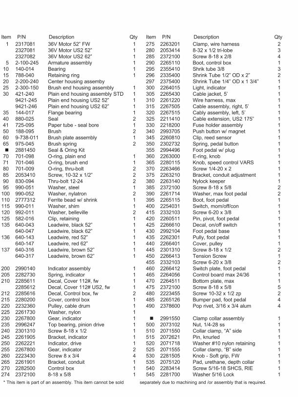
PA
RTS LIST
2991753 Bow guard assembly - 52” 1 2991752 Bow guard assembly - 62” 1 550 2281952 Bracket, top 1555 2280001 Bearing, top bracket 1560 2071541 Spring sleeve, upper 1565 2282704 Spring, bowguard 112 1570 2281525 Spacer, lower spring BG - 62” 1 575 2281540 Spring sleeve, lower 1580 2991730 Bracket, bottom 1585 2283413 Screw 3/8-16 x 1 SHCS, RIE 3
586 2282612 Pin, spring 5/16” SS 2
590 2266000 Bearing, ball, steel 1595 2266260 Bearing race 1600 2992092 Tube w/ bearing race - 52” 1 2992094 Tube w/ bearing race - 62” 1605 2267307 Bushing outer tube 1610 2266116 Bearing, Cartridge 1615 2266001 Bearing, split ring 1620 2261622 Collar half 2625 2263453 Screw, 1/4-20 x 1 SHCS 2630 2071560 Collar, Tube 1635 2223468 Screw 8-32 x 7/16 flt hd 4640 2032006 Tube 52” 1 2032007 Tube 62” 1
2991748 Mount, Fortrex, long 1700 2280800 Link, bowguard mount, left 1710 2287303 Bushing, upper pins 2711 2287304 Bushing, delrin 2715 2283409 Screw, 1/4-20 x 1” FHSC 4720 2880400 Pull grip assembly 1721 2261732 Washer 2725 2771601 Rope assembly 1730 2281516 Spacer, inner arm 1735 2281702 Washer, lock 1/4 1737 2284212 Outer arm, Long 1740 2992302 Rope guide assembly 1745 2281530 Insert, threaded 1750 2282608 Pin, 7/16 x 5 5/32 1751 2282602 Pin, 3/8 x 3 3/4 1752 2261505 Spacer 2753 2263011 E-ring, 3/8 shaft 2760 2223418 Screw, 1/4-20 x 1/2 BHCS 1765 2993821 Inner arm assembly, long 1770 2042711 Spring, torsion 1775 2283620 Latch, safety 1776 2282611 Pin, safety latch 1780 2281704 Washer 7/16 nylon 1785 2280805 Link, bowguard mount, right 1
790 2283410 Screw 1/4-20 x 1/2 PFH 2795 2288402 Gas spring (cylinder), 101#, lg mt 1796 2281710 Spacer, gas spring 2
800 2282610 Pin, upper, shock 1810 2280005 Bearing, nyliner 7/16” 4815 2282600 Pin, 7/16 x 4 7/8 1820 2281932 Bracket, rear pivot 2825 2281501 Yoke, shock mount 1830 2282606 Pin, 7/16 x 4 1/2 1835 2283402 Screw, set, 6-32 x 1/4 2845 2282604 Pin, Knurled 5/16 x 2 1850 2283615 Latch bar 1855 2283610 Bracket - latch/strap, rope pull 1860 2287300 Bushing, rear pivot 2865 2282602 Pin, 3/8 x 3 3/4 1870 2263011 E-ring, 3/8 shaft 2871 2280008 Bearing, Iglide 2875 2282720 Spring, extension 2880 2773601 Latch strap assembly, Long 1885 2261732 Washer 8, nylon 2890 2373450 Screw 8-18 x 3/8 2 2993915 Sideplate assembly, long, left, fw 1895 2288625 Support, left sideplate 1900 2283408 Screw 8 x 3/8 8905 2283915 Sideplate, long, left, fw 1910 2073408 Screw 1/4-20 x 7/8 2915 2286700 Plug, spacer 2920 2283900 Ramp, motor 1 2993925 Sideplate assembly, long, right, fw 1925 2288620 Support, right sideplate 1930 2283925 Sideplate, long, right, fw 1932 2285502 Decal, Sideplate, fw 2935 2281912 Base extrusion, long 1940 2323405 Screw 1/4-20 x 1/2 6950 2256300 Tiewrap 1955 2261238 Leadwire 1
975 2773806 Strap hold down 1
980 2991929 Bracket stabilizer assembly 1
1378160 Propeller kit WW2 [1000-1020] 2994876 Propeller bag assy [1010-1020]1000 2341160 Propeller WW2 11010 2262658 Drive pin, large 11015 2091701 Washer, prop, large 11020 2093101 Nut, nylock, prop, large 1
2994887 Mounting hardware bag assy
Item P/N Description Qty Item P/N Description Qty
P/N 2284912 REV. A ECN 34956 12/13
BA
TTERY C
ON
NEC
TION
BR
AN
CH
EMEN
T DE LA
BA
TTERIE
14
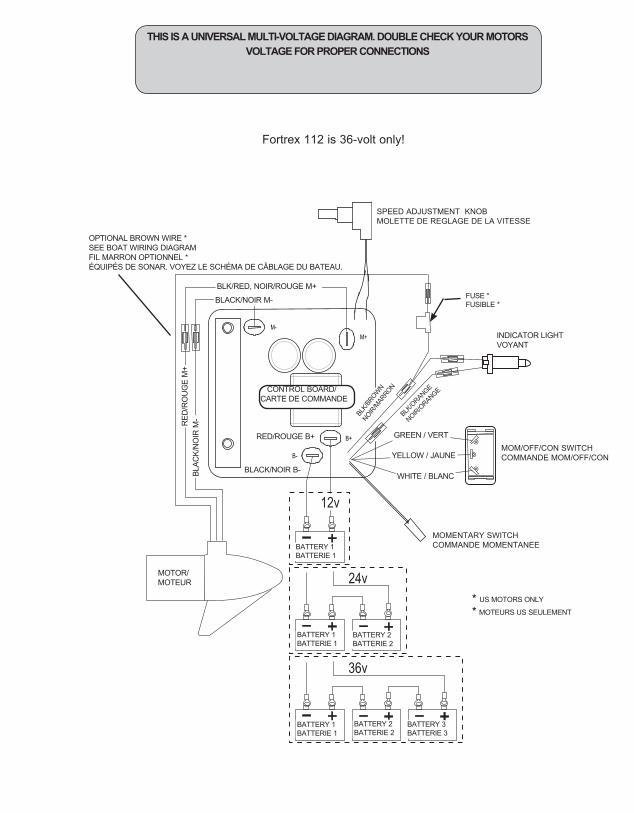
WARNING: • BEFORE CONNECTING BATTERY, MAKE SURE THE MOM/CON SWITCH IS IN THE OFF POSI-TION.• IMPROPER WIRING OF 24 OR 36 VOLT SYSTEMS COULD CAUSE BATTERY EXPLOSION!• KEEP LEADWIRE WING NUT CONNECTION TIGHT AND SOLID TO BATTERY TERMINALS.• LOCATE BATTERY IN A VENTILATED COMPART-MENT.
AVERTISSEMENT : • AVANT DE RACCORDER LA BATTERIE, VÉRIFIEZ QUE LA COMMANDE MOM/OFF/CON EST SUR ARRÊT.• UNE ERREUR DE POLARITÉ DANS UN CIRCUIT DE 24 V PEUT PROVOQUER L’EXPLOSION DE LA BATTERIE !• VEILLEZ À CE QUE LES ÉCROUS PAPILLONS SUR LES BORNES DE LA BATTERIE SOIENT BIEN SERRÉS. • PLACEZ LA BATTERIE DANS UN COMPARTIMENT AÉRÉ.
BATTERY CONNECTION:24 Volt Systems: FORTREX 801. Make sure that the motor is switched off (speed selector on
“0”). 2. Two 12 volt batteries are required.3. The batteries must be wired in series, only as directed in wir-
ing diagram, to provide 24 volts. a. Connect a connector cable to positive ( + ) terminal of bat-
tery 1 and to negative ( – ) terminal of battery 2. b. Connect positive (+) red lead to positive (+) terminal on
battery 2. c. Connect negative (–) black lead to negative (–) terminal of
battery 1.4. For safety reasons do not switch the motor on until the propel-
ler is in the water.
36 Volt Systems FORTREX 101 / 1121. Make sure that the motor is switched off (speed selector on “0”). 2. Three 12 volt batteries are required. 3. The batteries must be wired in series, only as directed in wiring
diagram, to provide 36 volts. a. Connect a connector cable to positive ( + ) terminal of battery
1 and to negative ( – ) terminal of battery 2. b. Connect a connector cable to positive (+) terminal of battery
2 and to negative (–) terminal of battery 3. c. Connect positive (+) red lead to positive (+) terminal on bat-
tery 3. d. Connect negative (–) black lead to negative (–) terminal of
battery 1.
4. For safety reasons do not switch the motor on until the propeller is in the water.
Note: Do not use your crank battery as one of the two or three supply batteries; crank batteries are not built for deep discharge service.
RACCORDEMENT DE LA BATTERIE :Systèmes de 24 V FORTREX 80 1. Assurer que le moteur est éteint (le sélectionneur de vitesse sur
“0”). 2. Deux 12 volts batteries sont exigés. 3. Le batteries doit être télégraphié en série, seulement comme
dirigé dans le schéma de connexions, fournir 24 volts. a. Raccordez un câble de connecteur à positif (+) le terminus de
batterie 1 et à négatif (-) le terminus de batterie 2. b. Communiquez positif (+) l’avance rouge à positif (+) le termi-
nus sur la batterie 2. c. Communiquez négatif (–) le graphite pour enduit à négatif (–)
le terminus de batterie 1.4. Pour la sécurité les raisons n’allument pas le moteur avant que
l’hélice ne soit dans l’eau.
Système de 36 V FORTREX 101 / 1121. Assurer que le moteur est éteint (le sélectionneur de vitesse sur
“0”). 2. Trois 12 volts batteries êtes exigés. 3. Le batteries doit être télégraphié en série, seulement comme dirigé
dans le schéma de connexions, fournir 36 volts. a. Raccordez un câble de connecteur à positif (+) le terminus de
batterie 1 et à négatif (-) le terminus de batterie 2. b. Raccordez un câble de connecteur à positif (–) le terminus de
batterie 2 et à négatif (–) le terminus de batterie 3. c. Communiquez positif (+) l’avance rouge à positif (+) le terminus
sur la batterie 3. d. Communiquer négatif (–) le graphite pour enduit à négatif (–) le
terminus de batterie 1.4. Pour la sécurité les raisons n’allument pas le moteur jusqu’à ce
que l’hélice soit dans l’eau.
En installant une prise de courant sur le leadwire, observez la polarité nécessaire et suivez des instructions dans votre manuel de propriétaire de bateau.Voir le schéma de connexions sur les pages suivantes.
WIR
ING
DIA
GR
AM
SC
HÉM
A D
E CÂ
BLA
GE
15
12v
24v
36v
B+
M-
B-
M+
BLK/RED, NOIR/ROUGE M+
BLACK/NOIR M-
CONTROL BOARD/CARTE DE COMMANDE
INDICATOR LIGHTVOYANT
BLACK/NOIR B-
RED/ROUGE B+
MOTOR/MOTEUR
MOMENTARY SWITCHCOMMANDE MOMENTANEE
SPEED ADJUSTMENT KNOBMOLETTE DE REGLAGE DE LA VITESSE
BATTERY 1BATTERIE 1
BATTERY 2BATTERIE 2
BATTERY 3BATTERIE 3
BATTERY 1BATTERIE 1
BATTERY 2BATTERIE 2
BATTERY 1BATTERIE 1
YELLOW / JAUNE
GREEN / VERT
WHITE / BLANC
BLK/
BROW
N
NOIR/M
ARRON
BLK/O
RANGE
NOIR/O
RANGE
OPTIONAL BROWN WIRE *SEE BOAT WIRING DIAGRAMFIL MARRON OPTIONNEL *ÉQUIPÉS DE SONAR. VOYEZ LE SCHÉMA DE CÂBLAGE DU BATEAU.
MOM/OFF/CON SWITCHCOMMANDE MOM/OFF/CON
RED
/RO
UG
E M
+BL
ACK/
NO
IR M
-
FUSE *FUSIBLE *
* US MOTORS ONLY
* MOTEURS US SEULEMENT
THIS IS A UNIVERSAL MULTI-VOLTAGE DIAGRAM. DOUBLE CHECK YOUR MOTORS VOLTAGE FOR PROPER CONNECTIONS
Fortrex 112 is 36-volt only!