Embed Size (px)
Citation preview
ROBOV. 010
MANUALE ISTRU ZIO NIE CATALOGO RICAMBI
LIVRET D’INSTRUCTIONS ET CATALOGUE DES RECHANGES
INSTRUCTIONS MANUALAND SPARE PARTS CATALOGUE
ANLEITUNGSHEFT UND ERSATZTEIL-KATALOG
Motoriduttore elettromeccanico per cancelli scorrevoli
Electromechanical gearmotor for sliding gates
MANUAL DE INSTRUCCIONES Y CATÁLOGO DE RECAMBIOS
Motorreductor electromecánico para cancelas correderas
Elektromechanischer Antrieb für Gleittore
Mototréducteur électromécanique pour portails coulissants
I GB F D E
QUESTO LIBRETTO È DESTINATO SOLO ALL'INSTALLATORE.L'installazione dovrà essere effettuata solamente da per so na le professionalmente qualifi cato in conformità a quanto previsto dalla legge n° 46 del 5 marzo 1990 e successive mo di fi che ed integrazioni e nel pieno rispetto delle norme UNI 8612.
ROBO
22
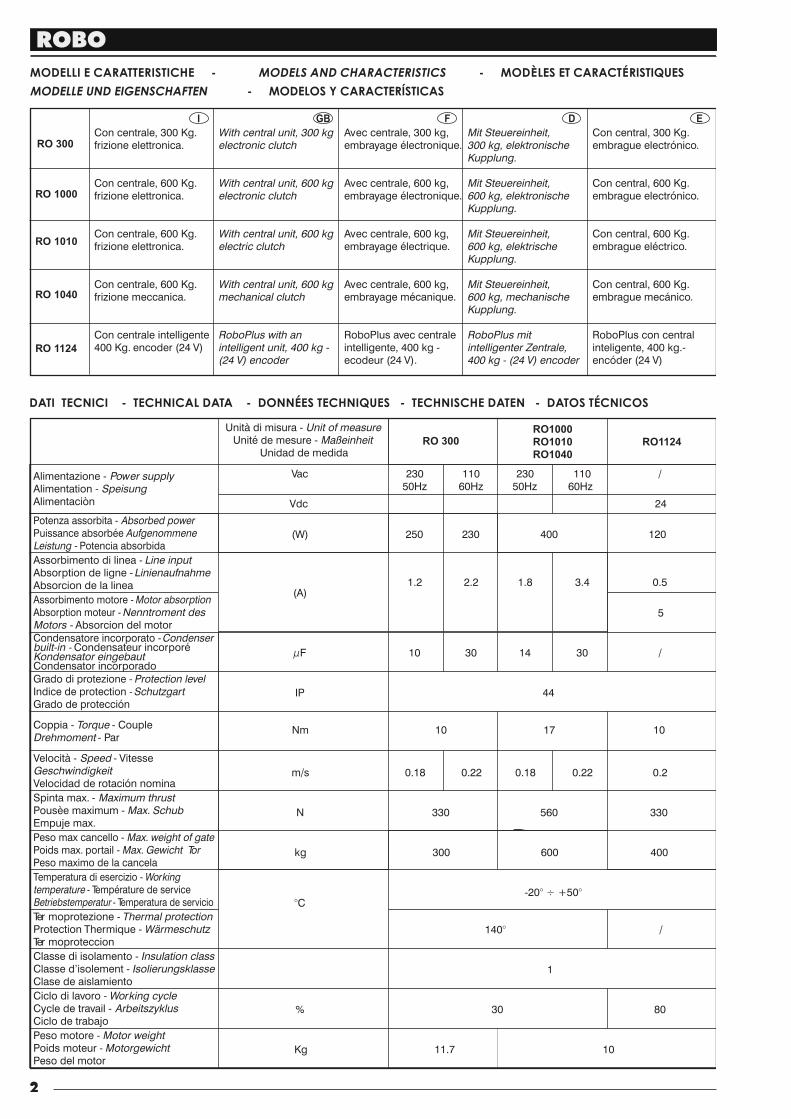
DATI TECNICI - TECHNICAL DATA - DONNÉES TECHNIQUES - TECHNISCHE DATEN - DATOS TÉCNICOS
MODELLI E CARATTERISTICHE - MODELS AND CHARACTERISTICS - MODÈLES ET CARACTÉRISTIQUES
MODELLE UND EIGENSCHAFTEN - MODELOS Y CARACTERÍSTICAS
Alimentazione - Power supplyAlimentation - SpeisungAlimentaciòn
Assorbimento motore - Motor absorptionAbsorption moteur - Nenntroment desMotors - Absorcion del motor
Assorbimento di linea - Line inputAbsorption de ligne -LinienaufnahmeAbsorcion de la linea
Potenza assorbita - Absorbed powerPuissance absorbée AufgenommeneLeistung - Potencia absorbida
Grado di protezione - Protection levelIndice de protection -SchutzgartGrado de protección
Condensatore incorporato -Condenserbuilt-in - Condensateur incorporéKondensator eingebautCondensator incorporado
Coppia - Torque - CoupleDrehmoment - Par
Velocità - Speed - VitesseGeschwindigkeitVelocidad de rotación nomina
Spinta max. - Maximum thrustPousèe maximum - Max. SchubEmpuje max.
Peso max cancello - Max. weight of gatePoids max. portail - Max. Gewicht TorPeso maximo de la cancela
Temperatura di esercizio - Workingtemperature - Température de serviceBetriebstemperatur - Temperatura de servicio
Classe di isolamento - Insulation classClasse d’isolement - IsolierungsklasseClase de aislamiento
Ter moprotezione - Thermal protectionProtection Thermique - WärmeschutzTer moproteccion
Ciclo di lavoro - Working cycleCycle de travail - ArbeitszyklusCiclo de trabajo
Peso motore - Motor weightPoids moteur - MotorgewichtPeso del motor
Unità di misura - Unit of measureUnité de mesure - Maßeinheit
Unidad de medida
Vac 230 110 230 110 /50Hz 60Hz 50Hz 60Hz
Vdc 24
(W) 250 230 400 120
(A)1.2 2.2 1.8 3.4 0.5
5
µF 10 30 14 30 /
IP 44
Nm 10 17 10
m/s 0.18 0.22 0.18 0.22 0.2
N 330 560 330
kg 300 600 400
°C-20 +50° ÷ °
140° /
1
% 30 80
Kg 10
RO 300
RO1000
RO1010
RO1040
RO1124
I GB F D E
RO 1000
RO 1010
RO 1040
RO 1124
Con central, 300 Kg.embrague electrónico.
Con central, 600 Kg.embrague electrónico.
Con central, 600 Kg.embrague eléctrico.
Con central, 600 Kg.embrague mecánico.
RoboPlus con centralinteligente, 400 kg.-encóder (24 V)
RO 300
Mit Steuereinheit,300 kg, elektronischeKupplung.
Mit Steuereinheit,600 kg, elektronischeKupplung.
Mit Steuereinheit,600 kg, elektrischeKupplung.
Mit Steuereinheit,600 kg, mechanischeKupplung.
RoboPlus mitintelligenter Zentrale,400 kg - (24 V) encoder
Avec centrale, 300 kg,embrayage électronique.
Avec centrale, 600 kg,embrayage électronique.
Avec centrale, 600 kg,embrayage électrique.
Avec centrale, 600 kg,embrayage mécanique.
RoboPlus avec centraleintelligente, 400 kg -ecodeur (24 V).
With central unit, 300 kgelectronic clutch
With central unit, 600 kgelectronic clutch
With central unit, 600 kgelectric clutch
With central unit, 600 kgmechanical clutch
RoboPlus with anintelligent unit, 400 kg -(24 V) encoder
Con centrale, 300 Kg.frizione elettronica.
Con centrale, 600 Kg.frizione elettronica.
Con centrale, 600 Kg.frizione elettronica.
Con centrale, 600 Kg.frizione meccanica.
Con centrale intelligente400 Kg. encoder (24 V)
11.7
ROBO
3
VERIFICHE E PRE LI MI NA RI
I GB F D E CHECKING AND PRELIMINARY PROCEDURES
CONTRÔLES PRÉLIMINAIRES
CONTROLES Y PRELIMINARES
A) Leer atentamente las
instrucciones.
B) Antes de efectuar la
instalación, comprobar que
la estructura de la cancela
sea robusta y adecuada.
C) Comprobar que la
cancela, durante todo su
movimiento, no pre sen te
puntos de roce y que no
exista peligro de
descarrilamiento.
D) Comprobar la presencia
de los costados de
seguridad.
A) Lire attentivement les
instructions.
B) Avant de passer à
l’installation, s’assurer que
la structure de la grille soit
solide et appropriée.
C) S’assurer que la grille
n’ait pas de points de
frottement durant tout le
mouvement et qu’il n’y a pas
de danger de déraillement.
D) S’assurer que les côtés
de sécurité sont présents
A) Read the instructions
carefully.
B) Before starting
installation, ensure that the
structure of the gate is
sturdy and appropriate.
C) Ensure that there is no
point of friction during the
entire movement of the gate.
and that there is no danger
of derailment.
D) Ensure that the safety
side panels are present.
A) Leggere at ten ta men te
le istruzioni.
B) Prima di passare al l'in -
stal la zio ne, ac cer tar si che
la struttura del can cel lo sia
solida ed ap pro pria ta.
C) Accertarsi che il can cel-
lo, durante tutto il suo mo vi -
men to, non su bi sca punti di
attrito e che non vi sia pe ri -
co lo di deragliamento.
D) Accertarsi della pre sen -
za dei franchi di sicurezza.
A) Lesen Sie die
Anleitungen aufmerksam
durch.
B) Vor der Installation
sicherstellen, daß die
Struktur Ihres Tors so li de
und für die Montage
geeignet ist.
C) Sicherstellen, daß das
Tor während der gesamten
Bewegung auf keine
Reibpunkte trifft und keine
E n t g l e i s u n g s g e f a h r
besteht.
D) Stellen Sie die Präsenz
der Sicherheitsflanken
sicher.
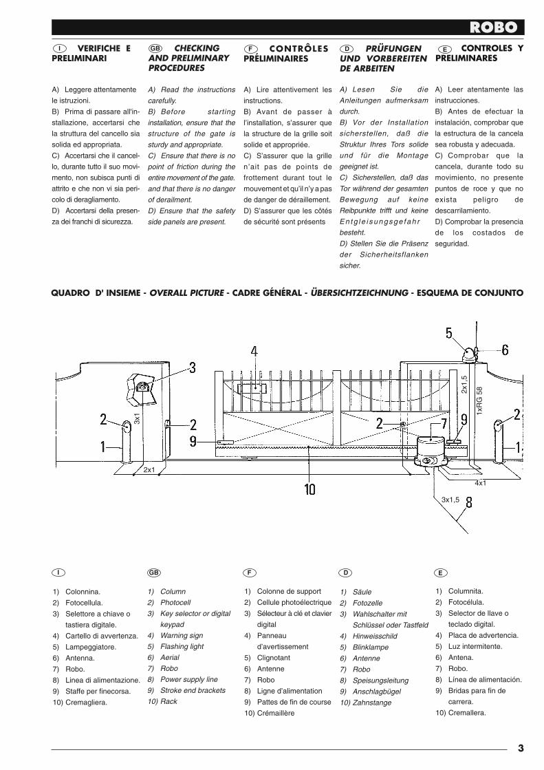
1) Colonnina.
2) Fotocellula.
3) Selettore a chiave o
tastiera digitale.
4) Cartello di avvertenza.
5) Lampeggiatore.
6) Antenna.
7) Robo.
8) Linea di alimentazione.
9) Staffe per fi necorsa.
10) Cremagliera.
I GB F D E
1) Colonne de support
2) Cellule photoélectrique
3) Sélecteur à clé et clavier
digital
4) Panneau
d’avertissement
5) Clignotant
6) Antenne
7) Robo
8) Ligne d’alimentation
9) Pattes de fi n de course
10) Crémaillère
1) Säule
2) Fotozelle
3) Wahlschalter mit
Schlüssel oder Tastfeld
4) Hinweisschild
5) Blinklampe
6) Antenne
7) Robo
8) Speisungsleitung
9) Anschlagbügel
10) Zahnstange
1) Columnita.
2) Fotocélula.
3) Selector de llave o
teclado digital.
4) Placa de advertencia.
5) Luz intermitente.
6) Antena.
7) Robo.
8) Línea de alimentación.
9) Bridas para fi n de
carrera.
10) Cremallera.
1) Column
2) Photocell
3) Key selector or digital
keypad
4) Warning sign
5) Flashing light
6) Aerial
7) Robo
8) Power supply line
9) Stroke end brackets
10) Rack
2x1,
5
QUADRO D' INSIEME - OVERALL PICTURE - CADRE GÉNÉRAL - ÜBERSICHTZEICHNUNG - ESQUEMA DE CONJUNTO
2x1
3x1,5
4x1
3x1 1x
RG
58
PRÜFUNGEN UND VORBEREITEN DE ARBEITEN
ROBO
4
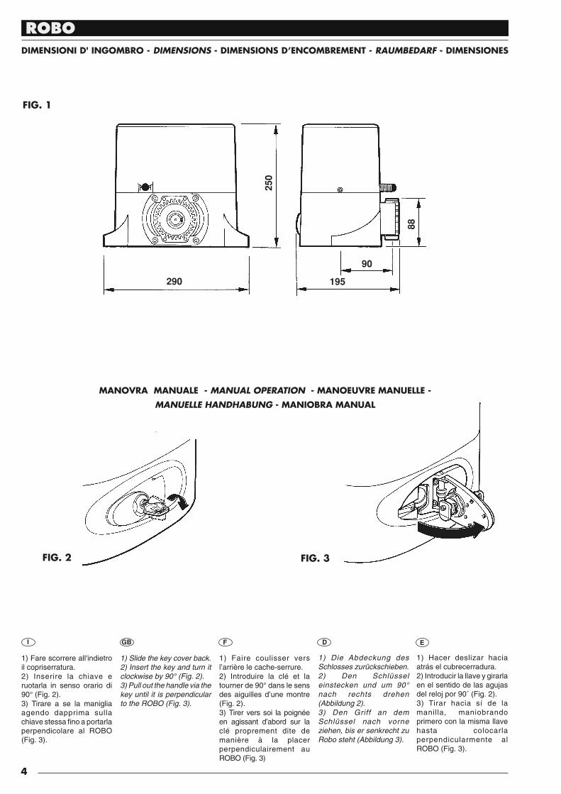
FIG. 1
29025
0
88
90
195
FIG. 2 FIG. 3
MANOVRA MANUALE - MANUAL OPERATION - MANOEUVRE MANUELLE -
MANUELLE HANDHABUNG - MANIOBRA MANUAL
DIMENSIONI D' INGOMBRO - DIMENSIONS - DIMENSIONS D’ENCOMBREMENT - RAUMBEDARF - DIMENSIONES
1) Slide the key cover back. 2) Insert the key and turn it clockwise by 90° (Fig. 2). 3) Pull out the handle via the key until it is perpendicular to the ROBO (Fig. 3).
1) Faire coulisser vers l’arrière le cache-serrure.2) Introduire la clé et la tourner de 90° dans le sens des aiguilles d’une montre (Fig. 2).3) Tirer vers soi la poignée en agissant d’abord sur la clé proprement dite de manière à la placer perpendiculairement au ROBO (Fig. 3)
1) Die Abdeckung des Schlosses zurückschieben.2) Den Schlüssel einstecken und um 90° nach rechts drehen (Abbildung 2). 3) Den Griff an dem Schlüssel nach vorne ziehen, bis er senkrecht zu Robo steht (Abbildung 3).
1) Hacer deslizar hacia atrás el cubrecerradura.2) Introducir la llave y girarla en el sentido de las agujas del reloj por 90˚ (Fig. 2).3) Tirar hacia sí de la manilla, maniobrando primero con la misma llave hasta colocarla perpendicularmente al ROBO (Fig. 3).
1) Fare scorrere al l'in die tro il copriserratura.2) Inserire la chiave e ruotarla in senso orario di 90° (Fig. 2).3) Tirare a se la maniglia agendo dapprima sulla chia ve stessa fi no a por tar la perpendicolare al ROBO (Fig. 3).
I GB F D E
ROBO
5
FIJACIÓN DE LA PLACA DE BASE
Respetando las medidas externas (Fig. 1), fi jar al suelo la placa de base mediante 4 resistentes tacos de expansión (Fig. 4), o bien introducir en hormigón la contraplaca.Preparar una o varias vainas para el paso de los cables eléctricos (Fig. 4).
Nota. Si la cancela supera los 200 kg de peso o bien trabaja en condiciones gravosas, es obligatorio sumergir totalmente en el hormigón la placa de base.
E
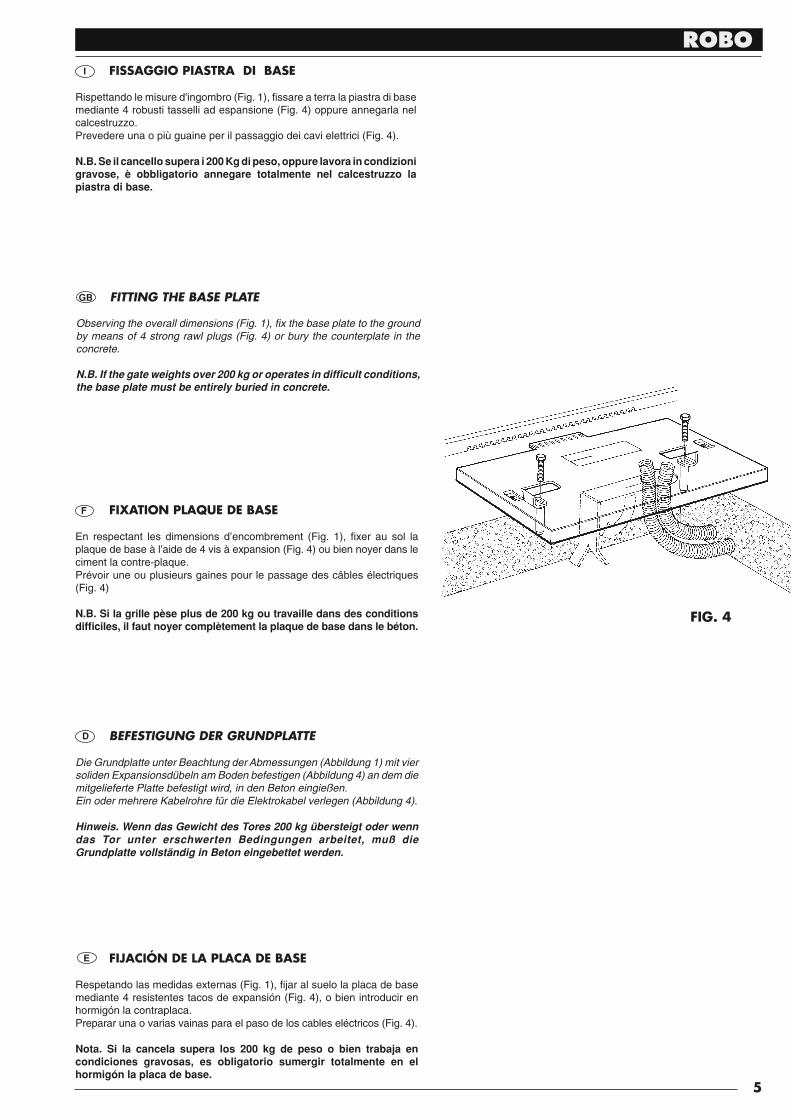
I FISSAGGIO PIASTRA DI BASE
Rispettando le misure d'in gom bro (Fig. 1), fi ssare a terra la piastra di base me dian te 4 robusti tasselli ad espansione (Fig. 4) oppure annegarla nel calcestruzzo.Prevedere una o più guaine per il passaggio dei cavi elet tri ci (Fig. 4).
N.B. Se il cancello supera i 200 Kg di peso, oppure lavora in condizioni gravose, è obbligatorio annegare totalmente nel calcestruzzo la piastra di base.
GB FITTING THE BASE PLATE
Observing the overall dimensions (Fig. 1), fi x the base plate to the ground by means of 4 strong rawl plugs (Fig. 4) or bury the counterplate in the concrete.
N.B. If the gate weights over 200 kg or operates in diffi cult conditions, the base plate must be entirely buried in concrete.
F FIXATION PLAQUE DE BASE
En respectant les dimensions d’encombrement (Fig. 1), fi xer au sol la plaque de base à l’aide de 4 vis à expansion (Fig. 4) ou bien noyer dans le ciment la contre-plaque.Prévoir une ou plusieurs gaines pour le passage des câbles électriques (Fig. 4)
N.B. Si la grille pèse plus de 200 kg ou travaille dans des conditions diffi ciles, il faut noyer complètement la plaque de base dans le béton.
D BEFESTIGUNG DER GRUNDPLATTE
Die Grundplatte unter Beachtung der Abmessungen (Abbildung 1) mit vier soliden Expansionsdübeln am Boden befestigen (Abbildung 4) an dem die mitgelieferte Platte befestigt wird, in den Beton eingießen.Ein oder mehrere Kabelrohre für die Elektrokabel verlegen (Abbildung 4).
Hinweis. Wenn das Gewicht des Tores 200 kg übersteigt oder wenn das Tor unter erschwerten Bedingungen arbeitet, muß die Grundplatte vollständig in Beton eingebettet werden.
FIG. 4
ROBO
6
FIG. 5
FIG. 7
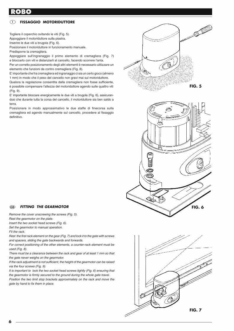
FITTING THE GEARMOTOR
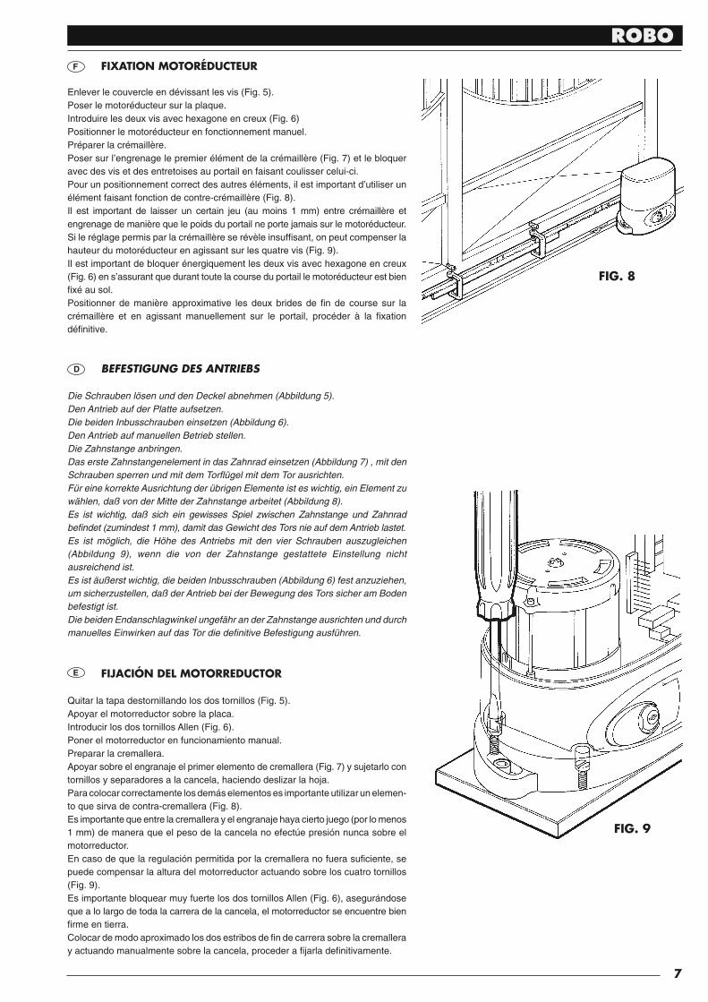
Remove the cover unscrewing the screws (Fig. 5). Rest the gearmotor on the plate. Insert the two socket head screws (Fig. 6). Set the gearmotor to manual operation. Fit the rack. Rest the fi rst rack element on the gear (Fig. 7) and lock it to the gate with screws and spacers, sliding the gate backwards and forwards. For correct positioning of the other elements, a counter-rack element must be used (Fig. 8). There must be a clearance between the rack and gear of at least 1 mm so that the gate never weighs on the gearmotor. If the rack adjustment is not suffi cient, the height of the gearmotor can be raised via the four screws (Fig. 9). It is important to lock the two socket head screws tightly (Fig. 6) ensuring that the gearmotor is fi rmly secured to the ground during the whole gate travel. Position the two limit stop brackets approximately on the rack and move the gate by hand to fi x them in place.
I
GB
Togliere il coperchio svitando le viti (Fig. 5).Appoggiare il motoriduttore sulla piastra.Inserire le due viti a brugola (Fig. 6).Posizionare il motoriduttore in funzionamento manuale.Predisporre la cremagliera.Appoggiare sul l'in gra nag gio il primo elemento di cremagliera (Fig. 7) e bloc car lo con viti e distanziarli al cancello, facendo scorrere l'anta.Per un corretto posizionamento degli altri elementi è necessario uti liz za re un ele men to che fun zio ni da contro cremagliera (Fig. 8).E' importante che fra cremagliera ed ingranaggio ci sia un certo gioco (almeno 1 mm) in modo che il peso del cancello non gravi mai sul motoriduttore.Qualora la regolazione con sen ti ta dalla cremagliera non fosse suffi ciente, è pos si bi le compensare l'altezza del motoriduttore agendo sulle quattro viti (Fig. 9). E' im por tan te bloccare ener gi ca men te le due viti a brugola (Fig. 6), as si cu ran-do si che durante tutta la cor sa del cancello, il motoriduttore sia ben saldo a terra.Posizionare in modo approssimativo le due staffe di fi necorsa sulla cremagliera ed agendo manualmente sul cancello, procedere al fi ssaggio defi nitivo.
FISSAGGIO MOTORIDUTTORE
FIG. 6
ROBO
7
FIG. 8
FIG. 9
FIXATION MOTORÉDUCTEUR
Enlever le couvercle en dévissant les vis (Fig. 5).Poser le motoréducteur sur la plaque.Introduire les deux vis avec hexagone en creux (Fig. 6)Positionner le motoréducteur en fonctionnement manuel.Préparer la crémaillère.Poser sur l’engrenage le premier élément de la crémaillère (Fig. 7) et le bloquer avec des vis et des entretoises au portail en faisant coulisser celui-ci.Pour un positionnement correct des autres éléments, il est important d’utiliser un élément faisant fonction de contre-crémaillère (Fig. 8).Il est important de laisser un certain jeu (au moins 1 mm) entre crémaillère et engrenage de manière que le poids du portail ne porte jamais sur le motoréducteur.Si le réglage permis par la crémaillère se révèle insuffi sant, on peut compenser la hauteur du motoréducteur en agissant sur les quatre vis (Fig. 9).Il est important de bloquer énergiquement les deux vis avec hexagone en creux (Fig. 6) en s’assurant que durant toute la course du portail le motoréducteur est bien fi xé au sol.Positionner de manière approximative les deux brides de fi n de course sur la crémaillère et en agissant manuellement sur le portail, procéder à la fi xation défi nitive.
F
BEFESTIGUNG DES ANTRIEBS
Die Schrauben lösen und den Deckel abnehmen (Abbildung 5).Den Antrieb auf der Platte aufsetzen.Die beiden Inbusschrauben einsetzen (Abbildung 6).Den Antrieb auf manuellen Betrieb stellen.Die Zahnstange anbringen.Das erste Zahnstangenelement in das Zahnrad einsetzen (Abbildung 7) , mit den Schrauben sperren und mit dem Torfl ügel mit dem Tor ausrichten.Für eine korrekte Ausrichtung der übrigen Elemente ist es wichtig, ein Element zu wählen, daß von der Mitte der Zahnstange arbeitet (Abbildung 8).Es ist wichtig, daß sich ein gewisses Spiel zwischen Zahnstange und Zahnrad befi ndet (zumindest 1 mm), damit das Gewicht des Tors nie auf dem Antrieb lastet.Es ist möglich, die Höhe des Antriebs mit den vier Schrauben auszugleichen (Abbildung 9), wenn die von der Zahnstange gestattete Einstellung nicht ausreichend ist.Es ist äußerst wichtig, die beiden Inbusschrauben (Abbildung 6) fest anzuziehen, um sicherzustellen, daß der Antrieb bei der Bewegung des Tors sicher am Boden befestigt ist.Die beiden Endanschlagwinkel ungefähr an der Zahnstange ausrichten und durch manuelles Einwirken auf das Tor die defi nitive Befestigung ausführen.
D
FIJACIÓN DEL MOTORREDUCTOR
Quitar la tapa destornillando los dos tornillos (Fig. 5).Apoyar el motorreductor sobre la placa.Introducir los dos tornillos Allen (Fig. 6).Poner el motorreductor en funcionamiento manual.Preparar la cremallera.Apoyar sobre el engranaje el primer elemento de cremallera (Fig. 7) y sujetarlo con tornillos y separadores a la cancela, haciendo deslizar la hoja.Para colocar correctamente los demás elementos es importante utilizar un ele men -to que sirva de contra-cremallera (Fig. 8).Es importante que entre la cremallera y el engranaje haya cierto juego (por lo menos 1 mm) de manera que el peso de la cancela no efectúe presión nunca sobre el motorreductor.En caso de que la regulación permitida por la cremallera no fuera sufi ciente, se puede compensar la altura del motorreductor actuando sobre los cuatro tornillos (Fig. 9).Es importante bloquear muy fuerte los dos tornillos Allen (Fig. 6), asegurándose que a lo largo de toda la carrera de la cancela, el motorreductor se encuentre bien fi rme en tierra.Colocar de modo aproximado los dos estribos de fi n de carrera sobre la cremallera y actuando ma nual men te sobre la cancela, pro ce der a fi jarla defi nitivamente.
E
ROBO
8
I
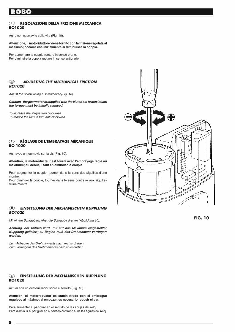
ADJUSTING THE MECHANICAL FRICTIONRO1020
Adjust the screw using a screwdriver (Fig. 10).
Caution - the gearmotor is supplied with the clutch set to maximum; the torque must be initially reduced.
To increase the torque turn clockwise. To reduce the torque turn anti-clockwise.
E
EINSTELLUNG DER MECHANISCHEN KUPPLUNG RO1020
Mit einem Schraubenzieher die Schraube drehen (Abbildung 10).
Achtung, der Antrieb wird mit auf das Maximum eingestellter Kupplung geliefert; zu Beginn muß das Drehmoment verringert werden.
Zum Anheben des Drehmoments nach rechts drehen.Zum Verringern des Drehmoments nach links drehen.
REGOLAZIONE DELLA FRIZIONE MECCANICARO1020
Agire con cacciavite sulla vite (Fig. 10).
Attenzione, il motoriduttore viene fornito con la frizione re go la ta al mas si mo; oc cor re che ini zial men te si di mi nu i sca la coppia.
Per aumentare la coppia ruotare in senso orario.Per diminuire la coppia ruotare in senso antiorario.
GB
F RÉGLAGE DE L’EMBRAYAGE MÉCANIQUERO 1020
Agir avec un tournevis sur la vis (Fig. 10).
Attention, le motoréducteur est fourni avec l’embrayage réglé au maximum; au début, il faut en diminuer le couple.
Pour augmenter le couple, tourner dans le sens des aiguilles d’une montre.Pour diminuer le couple, tourner dans le sens contraire aux aiguilles d’une montre.
D
FIG. 10
EINSTELLUNG DER MECHANISCHEN KUPPLUNGRO1020
Actuar con un destornillador sobre el tornillo (Fig. 10).
Atención, el motorreductor es suministrado con el embrague regulado al máximo; al empezar, es necesario reducir el par.
Para aumentar el par girar en el sentido de las agujas del reloj.Para disminuir el par girar en el sentido contrario al de las agujas del reloj.
ROBO
9
I
EINSTELLUNG DER ELEKTRISCHEN KUPPLUNG RO1010
D
Die Einstellung des Drehmoments erfolgt durch den integrierten Transformator.
Es gibt fünf Positionen mit der Anzeige 30 % bis 100 % (Abbildung 11)
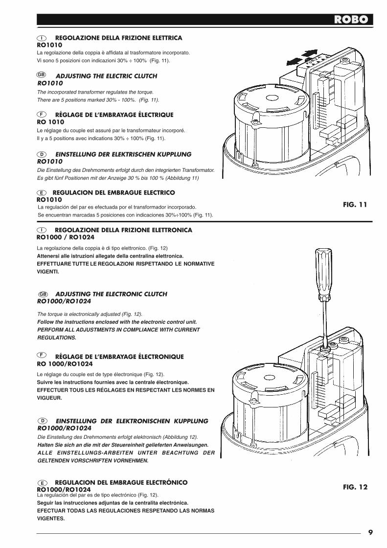
REGOLAZIONE DELLA FRIZIONE ELETTRICARO1010La regolazione della coppia è affi data al trasformatore incorporato.
Vi sono 5 posizioni con in di ca zio ni 30% ÷ 100% (Fig. 11).
ADJUSTING THE ELECTRIC CLUTCH RO1010GB
The incorporated transformer regulates the torque.
There are 5 positions marked 30% - 100%. (Fig. 11).
RÉGLAGE DE L’EMBRAYAGE ÉLECTRIQUE RO 1010
F
Le réglage du couple est assuré par le transformateur incorporé.
Il y a 5 positions avec indications 30% ÷ 100% (Fig. 11).
E REGULACION DEL EMBRAGUE ELECTRICO RO1010La regulación del par es efectuada por el transformador incorporado.
Se encuentran marcadas 5 posiciones con indicaciones 30%÷100% (Fig. 11).
I REGOLAZIONE DELLA FRIZIONE ELETTRONICARO1000 / RO1024
La regolazione della coppia è di tipo elettronico. (Fig. 12)
Attenersi alle istruzioni al le ga te del la centralina elettronica.
EFFETTUARE TUTTE LE REGOLAZIONI RI SPET TAN DO LE NORMATIVE
VIGENTI.
ADJUSTING THE ELECTRONIC CLUTCH RO1000/RO1024
The torque is electronically adjusted (Fig. 12).
Follow the instructions enclosed with the electronic control unit. PERFORM ALL ADJUSTMENTS IN COMPLIANCE WITH CURRENT REGULATIONS.
GB
RÉGLAGE DE L’EMBRAYAGE ÉLECTRONIQUE RO 1000/RO1024
Le réglage du couple est de type électronique (Fig. 12).
Suivre les instructions fournies avec la centrale électronique.
EFFECTUER TOUS LES RÉGLAGES EN RESPECTANT LES NORMES EN
VIGUEUR.
F
D EINSTELLUNG DER ELEKTRONISCHEN KUPPLUNG RO1000/RO1024Die Einstellung des Drehmoments erfolgt elektronisch (Abbildung 12).
Halten Sie sich an die mit der Steuereinheit gelieferten Anweisungen.ALLE EINSTELLUNGS-ARBEITEN UNTER BEACHTUNG DER GELTENDEN VORSCHRIFTEN VORNEHMEN.
E REGULACION DEL EMBRAGUE ELECTRÓNICO RO1000/RO1024La regulación del par es de tipo electrónico (Fig. 12).
Seguir las instrucciones adjuntas de la centralita electrónica.
EFECTUAR TODAS LAS REGULACIONES RESPETANDO LAS NORMAS
VIGENTES.
FIG. 11
FIG. 12
ROBO
10
CATALOGUE DES RECHANGES ERSATZTEILKATALOG CATÁLOGO DE RECAMBIOSED
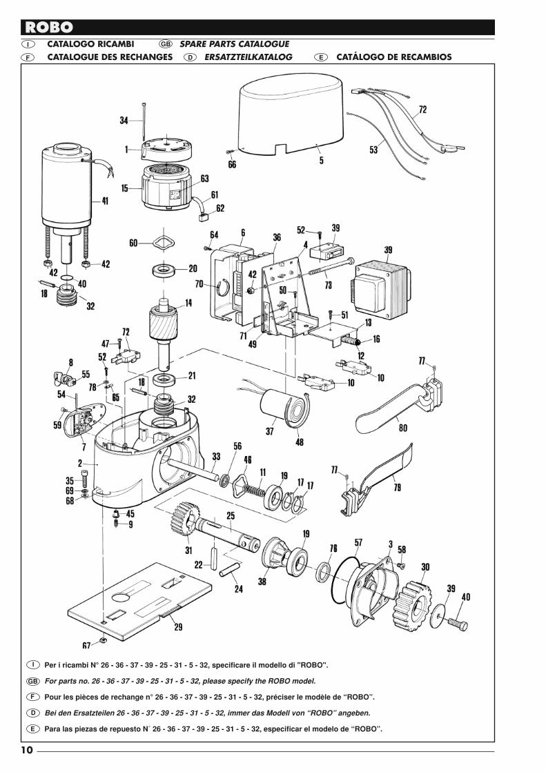
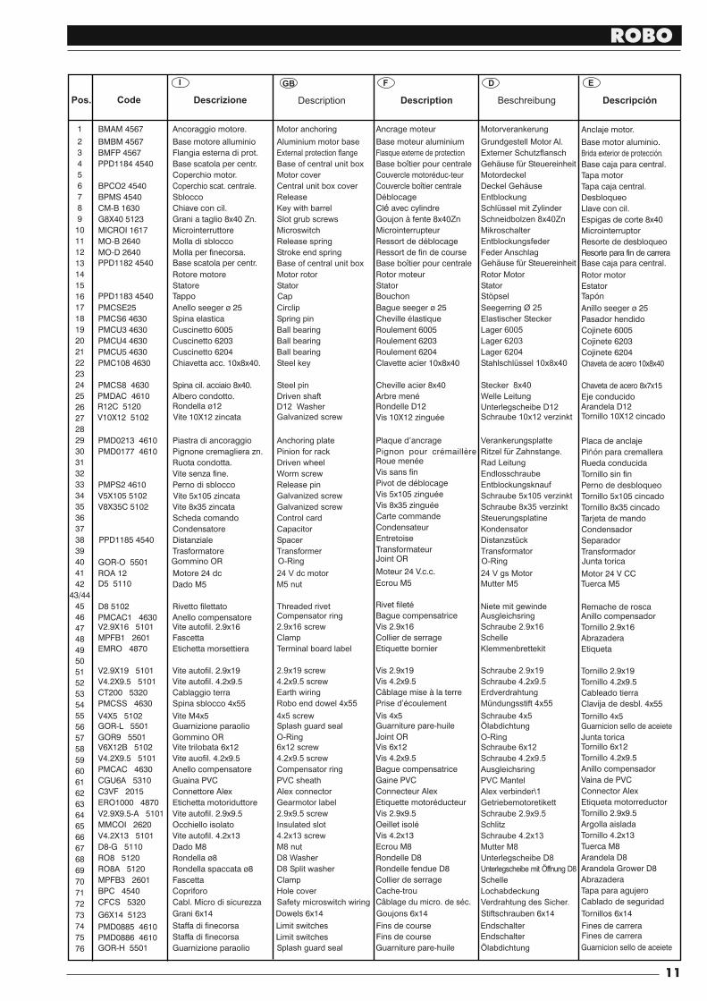
I CATALOGO RICAMBI SPARE PARTS CATALOGUE GB
F
Per i ricambi N° 26 - 36 - 37 - 39 - 25 - 31 - 5 - 32, spe ci fi ca re il modello di "ROBO".
For parts no. 26 - 36 - 37 - 39 - 25 - 31 - 5 - 32, please specify the ROBO model.
Pour les pièces de rechange n° 26 - 36 - 37 - 39 - 25 - 31 - 5 - 32, préciser le modèle de “ROBO”.
Bei den Ersatzteilen 26 - 36 - 37 - 39 - 25 - 31 - 5 - 32, immer das Modell von “ROBO” angeben.
Para las piezas de repuesto N˚ 26 - 36 - 37 - 39 - 25 - 31 - 5 - 32, especifi car el modelo de “ROBO”.
I
GB
F
D
E
ROBO
11
1
2
3
4
5
6
7
8
9
10
11
12
13
14
15
16
17
18
19
20
21
22
23
24
25
26
27
28
29
30
31
32
33
34
35
36
37
38
39
40
41
42
43/44
45
46
47
48
49
50
51
52
53
54
55
56
57
58
59
60
61
62
63
64
65
66
67
68
69
70
71
72
73
74
75
76
BMAM 4567
BMBM 4567
BMFP 4567
PPD1184 4540
BPCO2 4540
BPMS 4540
CM-B 1630
G8X40 5123
MICROI 1617
MO-B 2640
MO-D 2640
PMCSE25
PMCS6 4630
PMCU3 4630
PMCU4 4630
PMCU5 4630
PMC108 4630
PMCS8 4630
PMD0213 4610
PMD0177 4610
PMPS2 4610
V5X105 5102
V8X35C 5102
GOR-O 5501
ROA 12
D8 5102
PMCAC1 4630V2.9X16 5101
MPFB1 2601
EMRO 4870
V2.9X19 5101
V4.2X9.5 5101
CT200 5320
PMCSS 4630
V4X5 5102GOR-L 5501
GOR9 5501V6X12B 5102
V4.2X9.5 5101
PMCAC 4630
CGU6A 5310
C3VF 2015
ERO1000 4870
V2.9X9.5-A 5101
MMCOI 2620
V4.2X13 5101
D8-G 5110
RO8 5120
RO8A 5120
MPFB3 2601
BPC 4540
CFCS 5320
GOR-H 5501
Ancoraggio motore.
Base motore alluminio
Flangia esterna di prot.
Base scatola per centr.
Coperchio motor.
Coperchio scat. centrale.
Sblocco
Chiave con cil.
Grani a taglio 8x40 Zn.
Microinterruttore
Molla di sblocco
Molla per finecorsa.
Rotore motore
Statore
Anello seeger ø 25
Spina elastica
Cuscinetto 6005
Cuscinetto 6203
Cuscinetto 6204
Chiavetta acc. 10x8x40.
Spina cil. acciaio 8x40.
Albero condotto.
Piastra di ancoraggio
Pignone cremagliera zn.
Ruota condotta.
Vite senza fine.
Perno di sblocco
Vite 5x10⁵ zincata
Vite 8x35 zincata
Scheda comando
Condensatore
Distanziale
Trasformatore
Motore 24 dc
Rivetto filettato
Anello compensatoreVite autofil. 2.9x16
Fascetta
Etichetta morsettiera
Vite autofil. 2.9x19
Vite autofil. 4.2x9.5
Cablaggio terra
Spina sblocco 4x55
Vite M4x5Guarnizione paraolio
Gommino ORVite trilobata 6x12
Vite auofil. 4.2x9.5
Anello compensatore
Guaina PVC
Connettore Alex
Etichetta motoriduttore
Vite autofil. 2.9x9.5
Occhiello isolato
Vite autofil. 4.2x13
Dado M8
Rondella ø8
Rondella spaccata ø8
Fascetta
Copriforo
Cabl. Micro di sicurezza
Guarnizione paraolio
Motor anchoring
Aluminium motor baseExternal protection flangeBase of central unit boxMotor coverCentral unit box coverReleaseKey with barrelSlot grub screwsMicroswitchRelease springStroke end spring
Motor rotorStator
CirclipSpring pinBall bearingBall bearingBall bearingSteel key
Steel pinDriven shaft
Anchoring platePinion for rackDriven wheelWorm screwRelease pinGalvanized screwGalvanized screwControl cardCapacitorSpacerTransformer
24 V dc motor
Threaded rivetCompensator ring2.9x16 screwClampTerminal board label
2.9x19 screw4.2x9.5 screwEarth wiringRobo end dowel 4x55
4x5 screwSplash guard sealO-Ring6x12 screw4.2x9.5 screwCompensator ringPVC sheathAlex connectorGearmotor label2.9x9.5 screwInsulated slot4.2x13 screwM8 nutD8 WasherD8 Split washerClampHole coverSafety microswitch wiring
Splash guard seal
Descrizione DescriptionPos. Code Description
I GB D EF
Beschreibung
Ancrage moteur
Base moteur aluminium
Flasque externe de protection
Base boîtier pour centrale
Couvercle motor duc-teuréCouvercle boîtier centrale
D blocageéCl avec cylindreéGoujon à fente 8x40Zn
Microinterrupteur
Ressort de d blocageéRessort de fin de course
Rotor moteur
Stator
Bague seeger ø 25
Cheville lastiqueéRoulement 6005
Roulement 6203
Roulement 6204
Clavette acier 10x8x40
Cheville acier 8x40
Arbre mené
Plaque d’ancrage
Pignon pour cr maillèreéRoue men eéVis sans fin
Pivot de d blocageéVis 5x10⁵ zingu eéVis 8x35 zingu eéCarte commande
Condensateur
Entretoise
Transformateur
Moteur 24 V.c.c.
Rivet filetéBague compensatrice
Vis 2.9x16
Collier de serrage
Etiquette bornier
Vis 2.9x19
Vis 4.2x9.5
Câblage mise à la terre
Prise d’écoulement
Vis 4x5Guarniture pare-huile
Joint ORVis 6x12
Vis 4.2x9.5
Bague compensatrice
Gaine PVC
Connecteur Alex
Etiquette motor ducteuréVis 2.9x9.5
Oeillet isoléVis 4.2x13
Ecrou M8
Rondelle D8
Rondelle fendue D8
Collier de serrage
Cache-trou
Câblage du micro. de s c.é
Guarniture pare-huile
Motorverankerung
Grundgestell Motor Al.Externer SchutzflanschGehäuse für SteuereinheitMotordeckelDeckel GehäuseEntblockungSchlüssel mit ZylinderSchneidbolzen 8x40ZnMikroschalterEntblockungsfederFeder Anschlag
Rotor MotorStator
Seegerring Ø 25Elastischer SteckerLager 6005Lager 6203Lager 6204Stahlschlüssel 10x8x40
Stecker 8x40Welle Leitung
VerankerungsplatteRitzel für Zahnstange.Rad LeitungEndlosschraubeEntblockungsknaufSchraube 5x10⁵ verzinktSchraube 8x35 verzinktSteuerungsplatineKondensatorDistanzstückTransformator
24 V gs Motor
Niete mit gewindeAusgleichsringSchraube 2.9x16SchelleKlemmenbrettekit
Schraube 2.9x19Schraube 4.2x9.5ErdverdrahtungMündungsstift 4x55
Schraube 4x5ÖlabdichtungO-RingSchraube 6x12Schraube 4.2x9.5AusgleichsringPVC MantelAlex verbinder\1GetriebemotoretikettSchraube 2.9x9.5SchlitzSchraube 4.2x13Mutter M8Unterlegscheibe D8Unterlegscheibe mit Öffnung D8SchelleLochabdeckungVerdrahtung des Sicher.
Ölabdichtung
Anclaje motor.
Base motor aluminio.
Brida exterior de protección.
Base caja para central.
Tapa motor
Tapa caja central.
Desbloqueo
Llave con cil.
Espigas de corte 8x40
Microinterruptor
Resorte de desbloqueo
Resorte para fin de carrera
Rotor motor
Estator
Anillo seeger ø 25
Pasador hendido
Cojinete 6005
Cojinete 6203
Cojinete 6204
Chaveta de acero 10x8x40
Chaveta de acero 8x7x15
Eje conducido
Placa de anclaje
Pi ón para cremallerañ
Rueda conducida
Tornillo sin fin
Perno de desbloqueo
Tornillo 5x10⁵ cincado
Tornillo 8x35 cincado
Tarjeta de mando
Condensador
Separador
Transformador
Motor 24 V CC
Remache de roscaAnillo compensador
Tornillo 2.9x16
Abrazadera
Etiqueta
Tornillo 2.9x19
Tornillo 4.2x9.5
Cableado tierra
Clavija de desbl. 4x55
Tornillo 4x5Guarnicion sello de aceiete
Junta toricaTornillo 6x12
Tornillo 4.2x9.5
Anillo compensador
Vaina de PVC
Connector Alex
Etiqueta motorreductor
Tornillo 2.9x9.5
Argolla aislada
Tornillo 4.2x13
Tuerca M8
Arandela D8
Arandela Grower D8
Abrazadera
Tapa para agujero
Cablado de seguridad
Guarnicion sello de aceiete
Descripción
PMDAC 4610
PPD1185 4540
Gommino OR O-Ring Joint OR O-Ring Junta torica
D5 5110 Dado M5 M5 nut Ecrou M5 Mutter M5 Tuerca M5
R12C 5120
V10X12 5102 Vite 10X12 zincata Galvanized screw Vis 10X12 zingu eé Schraube 10x12 verzinkt Tornillo 10X12 cincadoRondella ø12 D12 Washer Rondelle D12 Unterlegscheibe D12 Arandela D12
PMD0886 4610
PMD0885 4610
G6X14 5123 Grani 6x14
Staffa di finecorsa
Staffa di finecorsa
Dowels 6x14 Goujons 6x14 Stiftschrauben 6x14 Tornillos 6x14
Limit switches
Limit switches
Fins de course
Fins de course
Endschalter
Endschalter
Fines de carreraFines de carrera
PPD1182 4540 Base scatola per centr. Base of central unit box Base boîtier pour centrale Gehäuse für Steuereinheit Base caja para central.
PPD1183 4540 Tappo Cap Bouchon Stöpsel Tapón
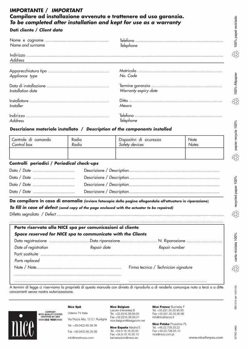
Dati cliente / Client data
Nome e cognome ....................................................Name and surname
Indirizzo ....................................................................................................................................................................Address
IMPORTANTE / IMPORTANTCompilare ad installazione avvenuta e trattenere ad uso garanzia.To be completed after installation and kept for use as a warranty
Telefono .........................................................................Telephone
Apparecchiatura tipo ...................................................Appliance type
Data di installazione ....................................................Installation date
Installatore ..................................................................Installer
Indirizzo .....................................................................Address
Matricola .......................................................................No. Code
Termine garanzia ...........................................................Warranty expiry date
Ditta ..............................................................................Messrs
Telefono .........................................................................Telephone
Controlli periodici / Periodical check-ups
Data / Date ................................... Descrizione / Description............................................................................
Data / Date ................................... Descrizione / Description............................................................................
Data / Date ................................... Descrizione / Description............................................................................
Data / Date ................................... Descrizione / Description............................................................................
Descrizione materiale installato / Description of the components installed
Da compilare in caso di anomalia (inviare fotocopia della pagina allegandola all'attuatore in riparazione)
To fi ll in case of defect (send copy of the page enclosed with the actuator to be repaired)
Difetto segnalato / Defect ...........................................................................................................................................
..................................................................................................................................................................................
Parte riservata alla NICE spa per comunicazioni al cliente Space reserved for NICE spa to communicate with the Clients Data registrazione ..................................Data riparazione............................... N. Riparazione ..............................
Date of registration Repair date Repair number
Parti sostituite .......................................................................................................................................................
Parts replaced
Note / Note....................................................................... Firma tecnico / Technician signature
.........................................................................................
........................................................................................ .................................................................A termini di legge ci riserviamo la proprietà di questo manuale con divieto di riprodurlo o di renderlo co mun que noto a terzi o a ditte concorrenti senza nostra au to riz za zio ne.
cart
a ric
icla
ta 1
00%
recy
cled
pap
er 1
00%
papi
er r
ecyc
le 1
00%
100%
Altp
apie
r10
0% p
apel
rec
icla
doIS
TR
O 4
865
RE
V.01
0 de
l 13/
01/0
5
Centrale di comando Radio Dispositivi di sicurezza NoteControl box Radio Safety devices Notes

control units
robo,thorIstruzioni ed avvertenze per l’installatore
Instructions and warnings for the fitter
Instructions et recommandations pour l’installateur
Anweisungen und Hinweise für den Installateur
Instrucciones y advertencias para el instalador
Instrukcje i uwagi dla instalatora

robo

GB
I
F
D
E
PL thorGB
I
F
D
E
PL
4
control unit gearmotorsrobo, thor
Warnings:
This manual has been especially written for use byqualified fitters. No information given in this manual can beconsidered as being of interest to end users! The control unit has been designed to control electro-mechanical actuators for automated swing gates ar doors;any other use is considered improper and is consequentlyforbidden by current laws. Do not install the unit before you have read all the instructions at leastonce.
!
Table of contents: page
1 Description of the product 5
2 Installation 52.1 Typical system layout 52.2 Electrical connections 62.2.1 Electrical diagram 62.2.2 Description of connections 62.2.3 Phototest 72.2.4 Checking connections 8
3 Adjustments 8
4 Testing 9
5 Operating modes 10
page
6 Programmable functions 106.1 Description of functions 11
7 How to... 12
8 Accessories 13
9 Maintenance 13
10 Disposal 13
11 What to do if... 13
12 Technical specifications 13
GB
5
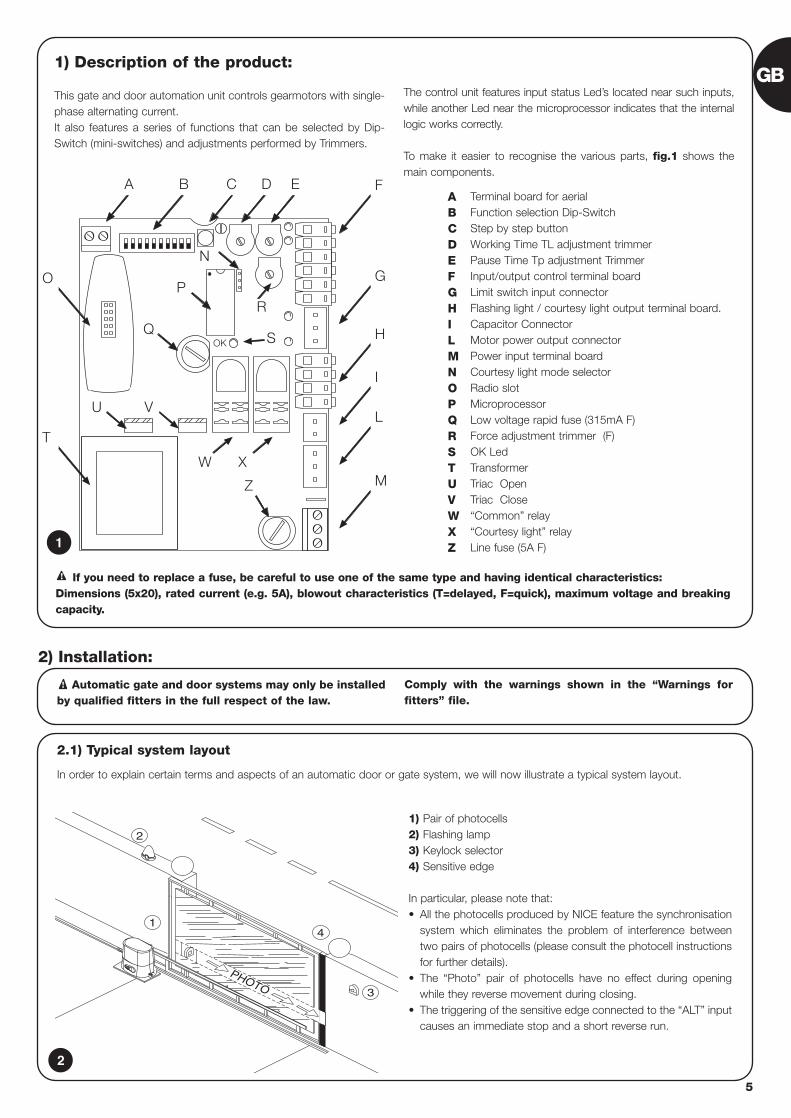
1) Description of the product:
This gate and door automation unit controls gearmotors with single-phase alternating current.It also features a series of functions that can be selected by Dip-Switch (mini-switches) and adjustments performed by Trimmers.
The control unit features input status Led’s located near such inputs,while another Led near the microprocessor indicates that the internallogic works correctly.
To make it easier to recognise the various parts, fig.1 shows themain components.
OK
BA C
R
D E F
G
H
I
L
M
P
S
Z
O
T
U V
Q
N
W X
Terminal board for aerialFunction selection Dip-SwitchStep by step buttonWorking Time TL adjustment trimmer Pause Time Tp adjustment Trimmer Input/output control terminal boardLimit switch input connectorFlashing light / courtesy light output terminal board.Capacitor ConnectorMotor power output connectorPower input terminal boardCourtesy light mode selectorRadio slotMicroprocessorLow voltage rapid fuse (315mA F)Force adjustment trimmer (F)OK Led TransformerTriac OpenTriac Close“Common” relay“Courtesy light” relayLine fuse (5A F)
ABCDEFGHILMNOPQRSTUVWXZ1
2.1) Typical system layout
In order to explain certain terms and aspects of an automatic door or gate system, we will now illustrate a typical system layout.
Automatic gate and door systems may only be installedby qualified fitters in the full respect of the law.
Comply with the warnings shown in the “Warnings forfitters” file.
!
2) Installation:
2
4
3
PHOTO
2
1
1) Pair of photocells2) Flashing lamp3) Keylock selector4) Sensitive edge
In particular, please note that:• All the photocells produced by NICE feature the synchronisation
system which eliminates the problem of interference betweentwo pairs of photocells (please consult the photocell instructionsfor further details).
• The “Photo” pair of photocells have no effect during openingwhile they reverse movement during closing.
• The triggering of the sensitive edge connected to the “ALT” inputcauses an immediate stop and a short reverse run.
If you need to replace a fuse, be careful to use one of the same type and having identical characteristics: Dimensions (5x20), rated current (e.g. 5A), blowout characteristics (T=delayed, F=quick), maximum voltage and breakingcapacity.
!
6
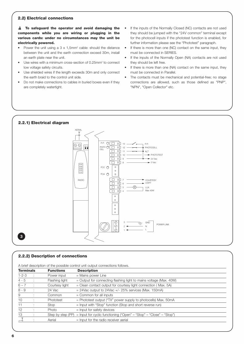
2.2.1) Electrical diagram
POWER LINE
P.P.
PHOTOCELL
FCA
FCC
PHOTOTEST
24 Vac
0 Vac
8
GND
LUXMax 40W
AERIAL
PHOTOCELL
P.P.
ALT11
10
9
12
13
COURTESY LIGHT
4
5
6
L
3
1
2
7
N
RADIO
2.2) Electrical connections
To safeguard the operator and avoid damaging thecomponents while you are wiring or plugging in thevarious cards: under no circumstances may the unit beelectrically powered.• Power the unit using a 3 x 1,5mm2 cable: should the distance
between the unit and the earth connection exceed 30m, installan earth plate near the unit.
• Use wires with a minimum cross-section of 0.25mm2 to connectlow voltage safety circuits.
• Use shielded wires if the length exceeds 30m and only connectthe earth braid to the control unit side.
• Do not make connections to cables in buried boxes even if theyare completely watertight.
• If the inputs of the Normally Closed (NC) contacts are not usedthey should be jumped with the “24V common” terminal exceptfor the photocell inputs if the phototest function is enabled, forfurther information please see the “Phototest” paragraph.
• If there is more than one (NC) contact on the same input, theymust be connected in SERIES.
• If the inputs of the Normally Open (NA) contacts are not usedthey should be left free.
• If there is more than one (NA) contact on the same input, theymust be connected in Parallel.
• The contacts must be mechanical and potential-free; no stageconnections are allowed, such as those defined as "PNP","NPN", "Open Collector" etc.
!
2.2.2) Description of connections
A brief description of the possible control unit output connections follows.Terminals Functions Description1-2-3 : Power input = Mains power Line4 - 5 : Flashing light = Output for connecting flashing light to mains voltage (Max. 40W)6 – 7 : Courtesy light = Clean contact output for courtesy light connection ( Max. 5A)8 - 9 : 24 Vac = 24Vac output to 24Vac +/- 25% services (Max. 150mA) 9 : Common = Common for all inputs10 : Phototest = Phototest output (“TX” power supply to photocells) Max. 50mA11 : Stop = Input with “Stop” function (Stop and short reverse run)12 : Photo = Input for safety devices13 : Step by step (PP) = Input for cyclic functioning (“Open” – “Stop” – “Close” – “Stop”)
: Aerial = Input for the radio receiver aerial
3
GB
7
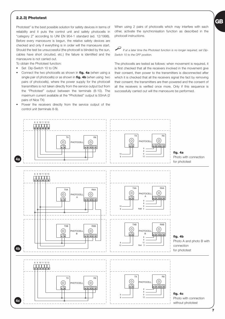
2.2.3) Phototest
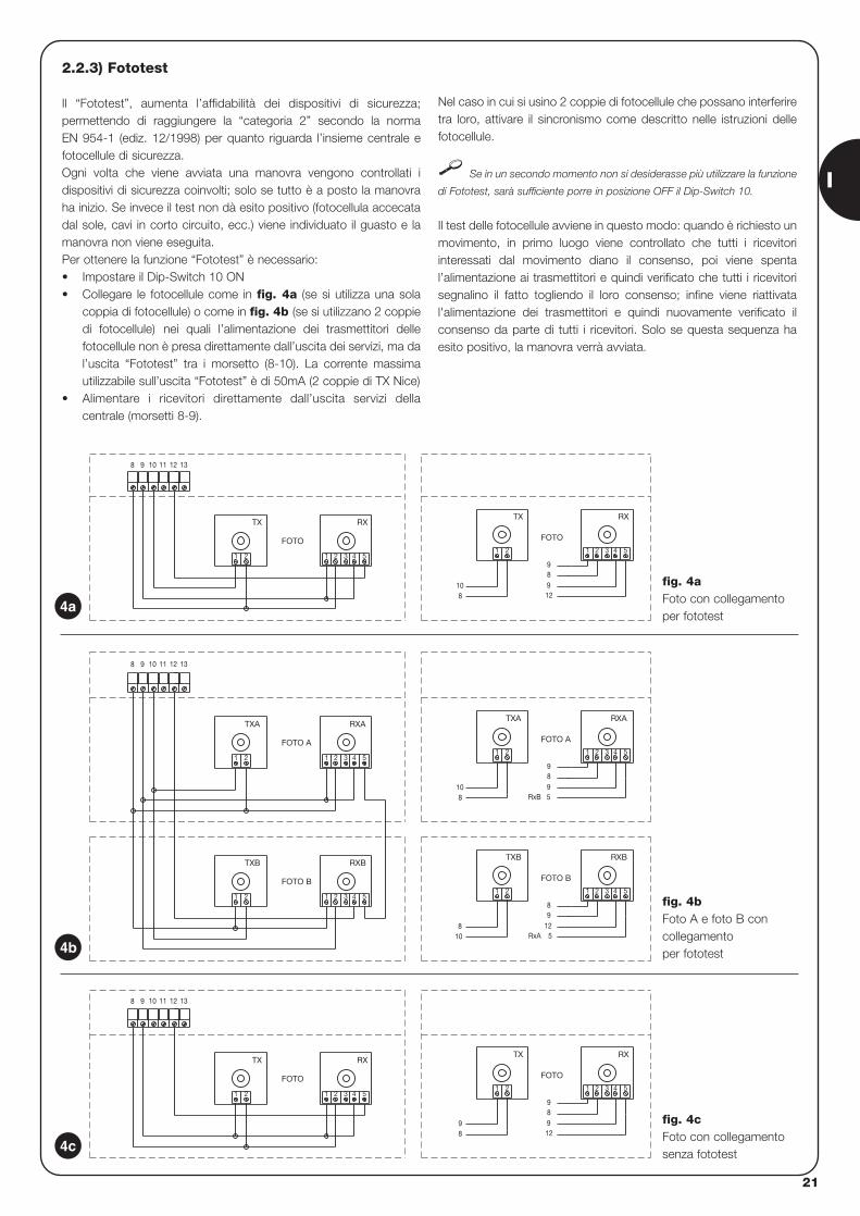
Phototest” is the best possible solution for safety devices in terms ofreliability and it puts the control unit and safety photocells in“category 2” according to UNI EN 954-1 standard (ed. 12/1998).Before every manoeuvre is begun, the relative safety devices arechecked and only if everything is in order will the manoeuvre start.Should the test be unsuccessful (the photocell is blinded by the sun,cables have short circuited, etc.) the failure is identified and themanoeuvre is not carried out.To obtain the Phototest function:• Set Dip-Switch 10 to ON • Connect the two photocells as shown in fig. 4a (when using a
single pair of photocells) or as shown in fig. 4b (when using twopairs of photocells), where the power supply for the photocelltransmitters is not taken directly from the service output but fromthe “Phototest” output between the terminals (8-10). Themaximum current available at the “Phototest” output is 50mA (2pairs of Nice TX)
• Power the receivers directly from the service output of thecontrol unit (terminals 8-9).
When using 2 pairs of photocells which may interfere with eachother, activate the synchronisation function as described in thephotocell instructions.
If at a later time the Phototest function is no longer required, set Dip-
Switch 10 to the OFF position.
The photocells are tested as follows: when movement is required, itis first checked that all the receivers involved in the movement givetheir consent, then power to the transmitters is disconnected afterwhich it is checked that all the receivers signal the fact by removingtheir consent; the transmitters are then powered and the consent ofall the receivers is verified once more. Only if this sequence issuccessfully carried out will the manoeuvre be performed.
3 4 5
RX
1 2
9
98
TX
21
98 12
RX
4 5
PHOTOCELL
321
TX
PHOTOCELL
21
1311 1298 10
RxA
RxB
5421 3
1298
PHOTOCELLB
5
RXBTXB
21
810
RXB
4 5321
TXB
PHOTOCELLB
21
5421 3
98
PHOTOCELLA
59
RXATXA
21
810
4 5
RXA
1311 12
2 31
TXA
PHOTOCELLA
1 2
98 10
12 13111098
RX
3 4 51 2
9
912
8
PHOTOCELL
1 2
108
RX
3 4 51 2
TX
1 2
PHOTOCELL
TX
4a
4b
4c
fig. 4aPhoto with connectionfor phototest
fig. 4bPhoto A and photo B withconnection for phototest
fig. 4cPhoto with connection without phototest
8
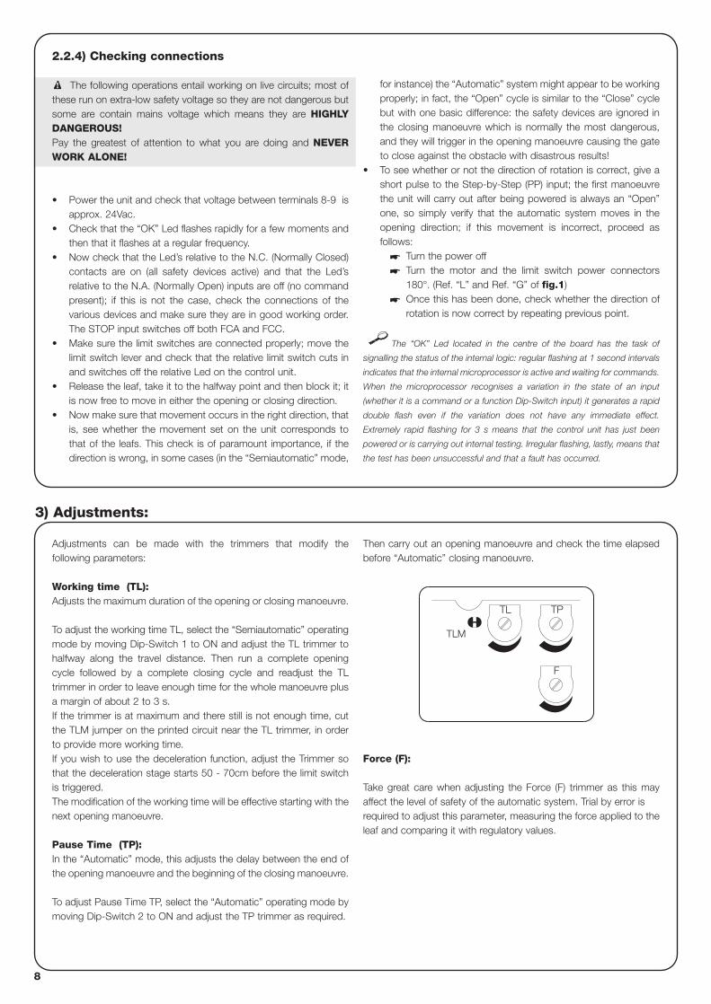
2.2.4) Checking connections
The following operations entail working on live circuits; most ofthese run on extra-low safety voltage so they are not dangerous butsome are contain mains voltage which means they are HIGHLYDANGEROUS!Pay the greatest of attention to what you are doing and NEVERWORK ALONE!
• Power the unit and check that voltage between terminals 8-9 isapprox. 24Vac.
• Check that the “OK” Led flashes rapidly for a few moments andthen that it flashes at a regular frequency.
• Now check that the Led’s relative to the N.C. (Normally Closed)contacts are on (all safety devices active) and that the Led’srelative to the N.A. (Normally Open) inputs are off (no commandpresent); if this is not the case, check the connections of thevarious devices and make sure they are in good working order.The STOP input switches off both FCA and FCC.
• Make sure the limit switches are connected properly; move thelimit switch lever and check that the relative limit switch cuts inand switches off the relative Led on the control unit.
• Release the leaf, take it to the halfway point and then block it; itis now free to move in either the opening or closing direction.
• Now make sure that movement occurs in the right direction, thatis, see whether the movement set on the unit corresponds tothat of the leafs. This check is of paramount importance, if thedirection is wrong, in some cases (in the “Semiautomatic” mode,
for instance) the “Automatic” system might appear to be workingproperly; in fact, the “Open” cycle is similar to the “Close” cyclebut with one basic difference: the safety devices are ignored inthe closing manoeuvre which is normally the most dangerous,and they will trigger in the opening manoeuvre causing the gateto close against the obstacle with disastrous results!
• To see whether or not the direction of rotation is correct, give ashort pulse to the Step-by-Step (PP) input; the first manoeuvrethe unit will carry out after being powered is always an “Open”one, so simply verify that the automatic system moves in theopening direction; if this movement is incorrect, proceed asfollows:
� Turn the power off� Turn the motor and the limit switch power connectors
180°. (Ref. “L” and Ref. “G” of fig.1)� Once this has been done, check whether the direction of
rotation is now correct by repeating previous point.
The “OK” Led located in the centre of the board has the task of
signalling the status of the internal logic: regular flashing at 1 second intervals
indicates that the internal microprocessor is active and waiting for commands.
When the microprocessor recognises a variation in the state of an input
(whether it is a command or a function Dip-Switch input) it generates a rapid
double flash even if the variation does not have any immediate effect.
Extremely rapid flashing for 3 s means that the control unit has just been
powered or is carrying out internal testing. Irregular flashing, lastly, means that
the test has been unsuccessful and that a fault has occurred.
!
Adjustments can be made with the trimmers that modify thefollowing parameters:
Working time (TL): Adjusts the maximum duration of the opening or closing manoeuvre.
To adjust the working time TL, select the “Semiautomatic” operatingmode by moving Dip-Switch 1 to ON and adjust the TL trimmer tohalfway along the travel distance. Then run a complete openingcycle followed by a complete closing cycle and readjust the TLtrimmer in order to leave enough time for the whole manoeuvre plusa margin of about 2 to 3 s.If the trimmer is at maximum and there still is not enough time, cutthe TLM jumper on the printed circuit near the TL trimmer, in orderto provide more working time.If you wish to use the deceleration function, adjust the Trimmer sothat the deceleration stage starts 50 - 70cm before the limit switchis triggered. The modification of the working time will be effective starting with thenext opening manoeuvre.
Pause Time (TP):In the “Automatic” mode, this adjusts the delay between the end ofthe opening manoeuvre and the beginning of the closing manoeuvre.
To adjust Pause Time TP, select the “Automatic” operating mode bymoving Dip-Switch 2 to ON and adjust the TP trimmer as required.
Then carry out an opening manoeuvre and check the time elapsedbefore “Automatic” closing manoeuvre.
Force (F):
Take great care when adjusting the Force (F) trimmer as this mayaffect the level of safety of the automatic system. Trial by error isrequired to adjust this parameter, measuring the force applied to theleaf and comparing it with regulatory values.
3) Adjustments:
F
TL TP
TLM
GB
9
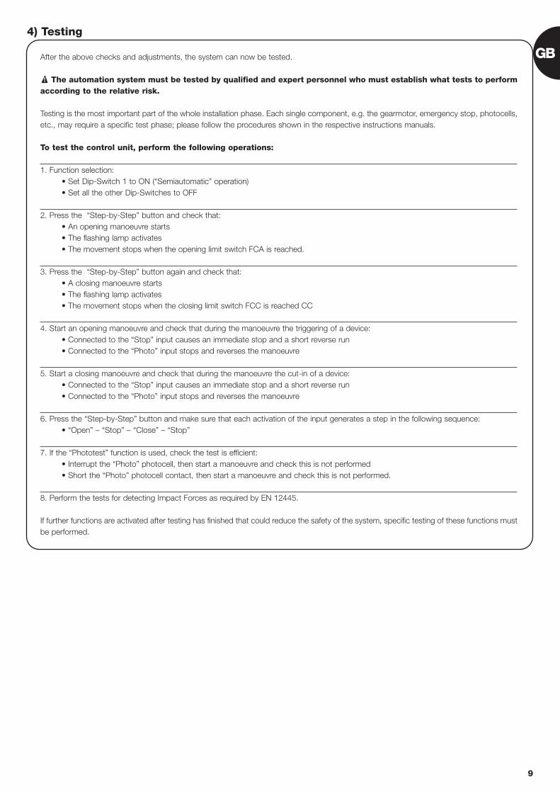
After the above checks and adjustments, the system can now be tested.
The automation system must be tested by qualified and expert personnel who must establish what tests to performaccording to the relative risk.
Testing is the most important part of the whole installation phase. Each single component, e.g. the gearmotor, emergency stop, photocells,etc., may require a specific test phase; please follow the procedures shown in the respective instructions manuals.
To test the control unit, perform the following operations:
1. Function selection: • Set Dip-Switch 1 to ON (“Semiautomatic” operation)• Set all the other Dip-Switches to OFF
2. Press the “Step-by-Step” button and check that:• An opening manoeuvre starts• The flashing lamp activates• The movement stops when the opening limit switch FCA is reached.
3. Press the “Step-by-Step” button again and check that:• A closing manoeuvre starts• The flashing lamp activates• The movement stops when the closing limit switch FCC is reached CC
4. Start an opening manoeuvre and check that during the manoeuvre the triggering of a device:• Connected to the “Stop” input causes an immediate stop and a short reverse run• Connected to the “Photo” input stops and reverses the manoeuvre
5. Start a closing manoeuvre and check that during the manoeuvre the cut-in of a device:• Connected to the “Stop” input causes an immediate stop and a short reverse run• Connected to the “Photo” input stops and reverses the manoeuvre
6. Press the “Step-by-Step” button and make sure that each activation of the input generates a step in the following sequence:• “Open” – “Stop” – “Close” – “Stop”
7. If the “Phototest” function is used, check the test is efficient:• Interrupt the “Photo” photocell, then start a manoeuvre and check this is not performed• Short the “Photo” photocell contact, then start a manoeuvre and check this is not performed.
8. Perform the tests for detecting Impact Forces as required by EN 12445.
If further functions are activated after testing has finished that could reduce the safety of the system, specific testing of these functions mustbe performed.
!
4) Testing

10
5) Operating modes
In the manual operating mode, the “Step-by-Step” input enables analternating closing and opening manoeuvre.Movement stops as soon as the input command stops. During anopening or closing manoeuvre, movement will stop also when the limitswitches are triggered; moreover, during a closing manoeuvre,movement will stop also if the “Photocell” enable signal fails. During bothopening and closing manoeuvres, the activation of the “ALT” commandwill always cause an immediate stopping of movement and a shortreverse run. When a movement is stopped, stop the input commandbefore giving a command to start a new movement.When one of the automatic functioning modes (“Semiautomatic”,“Automatic” o “Close Always”) is operational, a command impulse tothe “Step by step” input begins an alternating closing and openingmanoeuvre. A second impulse to the “Step by step” will cause it to stop.
Both in the opening and closing phases, the activation of the “ALT”command will cause an immediate stopping of movement and ashort reverse run.
If an automatic functioning mode has been chosen, the openingmanoeuvre will be followed by a pause and then a closingmanoeuvre. If “Photocell” triggers during the pause, the timer will bereset with a new pause time; if, on the other hand, there is a “Stop”during the pause, the closing function will be cancelled and thesystem will “Stop”.Nothing will happen if “Photocell” triggers during an openingmanoeuvre; if “Photocell” triggers during a closing manoeuvre, thiswill invert the direction of movement followed by a pause and then aclosing manoeuvre.
The unit features a set of microswitches used to operate variousfunctions so as to make the system more suitable to user needs andsafer in various conditions of use. All the functions can be activated bymoving the relative Dip-Switch to the “On” position and deactivated bymoving them to “Off”.
Some of the programmable functions are linked tosafety aspects; carefully evaluate the effects of a functionand see which gives the highest possible level of safety.
!
Use the Dip-Switches to select the various operating modes and add the functions required according to this table:
Switch 1-2: Off-Off = “Manual” movement (i.e.: man Present)On -Off = “Semiautomatic” movementOff-On = Automatic” movement (i.e.: automatic closingOn -On = “Automatic + always “Closes” movement
Switch 3: On = Condominium operating mode <not available in the manual mode>Switch 4: On = Pre-flashingSwitch 5: On = Close 5” after “Photo” < in “Automatic” > or “Close” after Photo <in “Semiautomatic” >Switch 6: On = “Photo” safety also in openingSwitch 7: On = Gradual departureSwitch 8: On = DecelerationSwitch 9: On = BrakeSwitch 10: On = PhototestSelector switch JP1: = Courtesy light in impulse mode
6) Programmable functions
101
JP1
GB
11
6.1) Description of functions
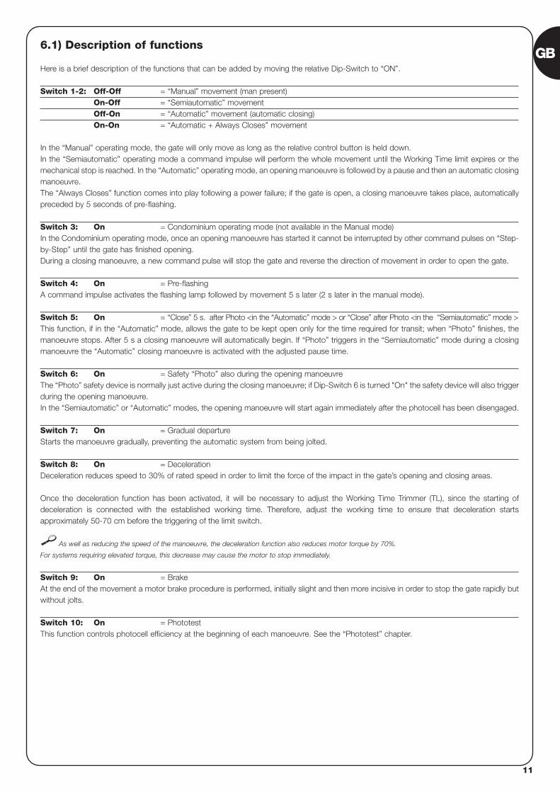
Here is a brief description of the functions that can be added by moving the relative Dip-Switch to “ON”.
Switch 1-2: Off-Off = “Manual” movement (man present)On-Off = “Semiautomatic” movementOff-On = “Automatic” movement (automatic closing)On-On = “Automatic + Always Closes” movement
In the “Manual” operating mode, the gate will only move as long as the relative control button is held down. In the “Semiautomatic” operating mode a command impulse will perform the whole movement until the Working Time limit expires or themechanical stop is reached. In the “Automatic” operating mode, an opening manoeuvre is followed by a pause and then an automatic closingmanoeuvre.The “Always Closes” function comes into play following a power failure; if the gate is open, a closing manoeuvre takes place, automaticallypreceded by 5 seconds of pre-flashing.
Switch 3: On = Condominium operating mode (not available in the Manual mode)In the Condominium operating mode, once an opening manoeuvre has started it cannot be interrupted by other command pulses on “Step-by-Step” until the gate has finished opening.During a closing manoeuvre, a new command pulse will stop the gate and reverse the direction of movement in order to open the gate.
Switch 4: On = Pre-flashingA command impulse activates the flashing lamp followed by movement 5 s later (2 s later in the manual mode).
Switch 5: On = “Close” 5 s. after Photo <in the “Automatic” mode > or “Close” after Photo <in the “Semiautomatic” mode >This function, if in the “Automatic” mode, allows the gate to be kept open only for the time required for transit; when “Photo” finishes, themanoeuvre stops. After 5 s a closing manoeuvre will automatically begin. If “Photo” triggers in the “Semiautomatic” mode during a closingmanoeuvre the “Automatic” closing manoeuvre is activated with the adjusted pause time.
Switch 6: On = Safety “Photo” also during the opening manoeuvreThe “Photo” safety device is normally just active during the closing manoeuvre; if Dip-Switch 6 is turned "On" the safety device will also triggerduring the opening manoeuvre.In the “Semiautomatic” or “Automatic” modes, the opening manoeuvre will start again immediately after the photocell has been disengaged.
Switch 7: On = Gradual departureStarts the manoeuvre gradually, preventing the automatic system from being jolted.
Switch 8: On = Deceleration Deceleration reduces speed to 30% of rated speed in order to limit the force of the impact in the gate’s opening and closing areas.
Once the deceleration function has been activated, it will be necessary to adjust the Working Time Trimmer (TL), since the starting ofdeceleration is connected with the established working time. Therefore, adjust the working time to ensure that deceleration startsapproximately 50-70 cm before the triggering of the limit switch.
As well as reducing the speed of the manoeuvre, the deceleration function also reduces motor torque by 70%.
For systems requiring elevated torque, this decrease may cause the motor to stop immediately.
Switch 9: On = BrakeAt the end of the movement a motor brake procedure is performed, initially slight and then more incisive in order to stop the gate rapidly butwithout jolts.
Switch 10: On = PhototestThis function controls photocell efficiency at the beginning of each manoeuvre. See the “Phototest” chapter.
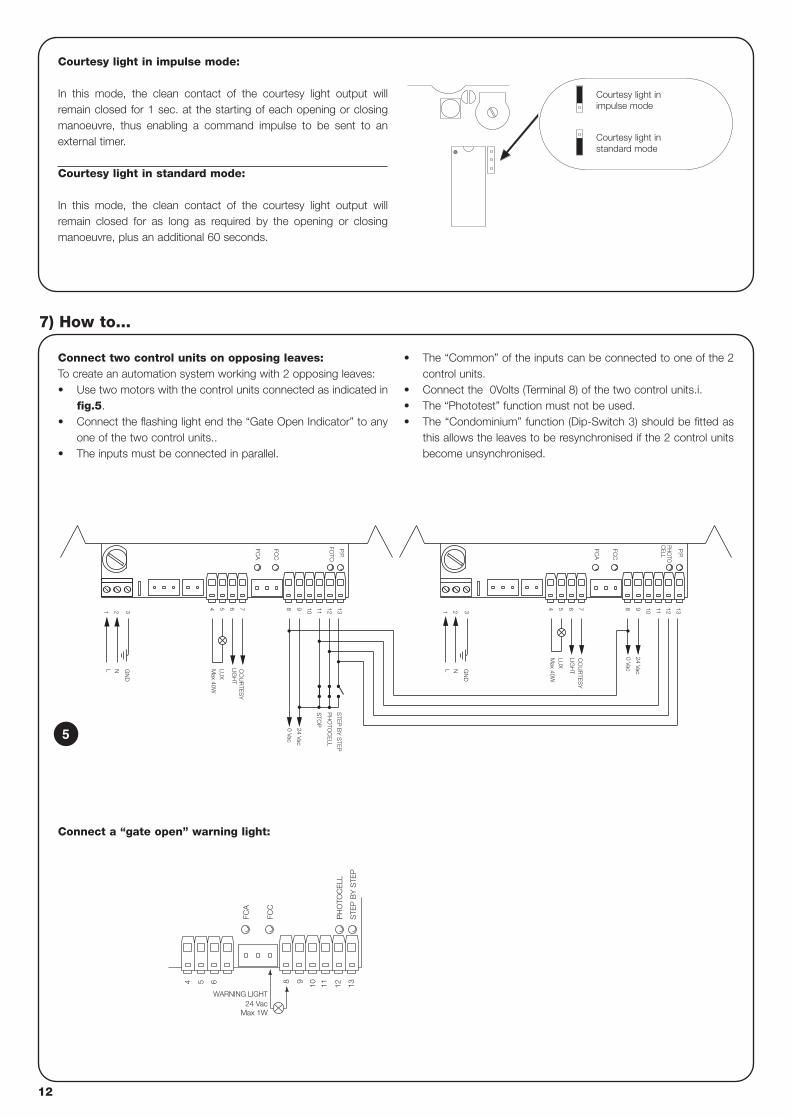
Connect two control units on opposing leaves:To create an automation system working with 2 opposing leaves: • Use two motors with the control units connected as indicated in
fig.5.• Connect the flashing light end the “Gate Open Indicator” to any
one of the two control units..• The inputs must be connected in parallel.
• The “Common” of the inputs can be connected to one of the 2control units.
• Connect the 0Volts (Terminal 8) of the two control units.i.• The “Phototest” function must not be used.• The “Condominium” function (Dip-Switch 3) should be fitted as
this allows the leaves to be resynchronised if the 2 control unitsbecome unsynchronised.
7) How to...
N
7
21 3
L
654
CO
UR
TES
YLIG
HT
13129 10 11S
TOP
P.P.
FOTO
Max 40W
LUX
GN
D
8
0 Vac
24 Vac
FCC
FCA
PH
OTO
CE
LL
STE
P B
Y S
TEP
11
0 Vac
24 Vac
LIGH
T
Max 40W
GN
D3
NL
1 2
LUX
CO
UR
TES
Y
54 76 8 9 10
FCA
FCC
12 13
PHO
TOC
ELL
P.P.
5
Courtesy light in impulse mode:
In this mode, the clean contact of the courtesy light output willremain closed for 1 sec. at the starting of each opening or closingmanoeuvre, thus enabling a command impulse to be sent to anexternal timer.
Courtesy light in standard mode:
In this mode, the clean contact of the courtesy light output willremain closed for as long as required by the opening or closingmanoeuvre, plus an additional 60 seconds.
Courtesy light inimpulse mode
Courtesy light instandard mode
FCC
FCA
STE
P B
Y S
TEP
54 6 1198 10 12 13
24 VacWARNING LIGHT
Max 1W
PH
OTO
CE
LL
Connect a “gate open” warning light:
12
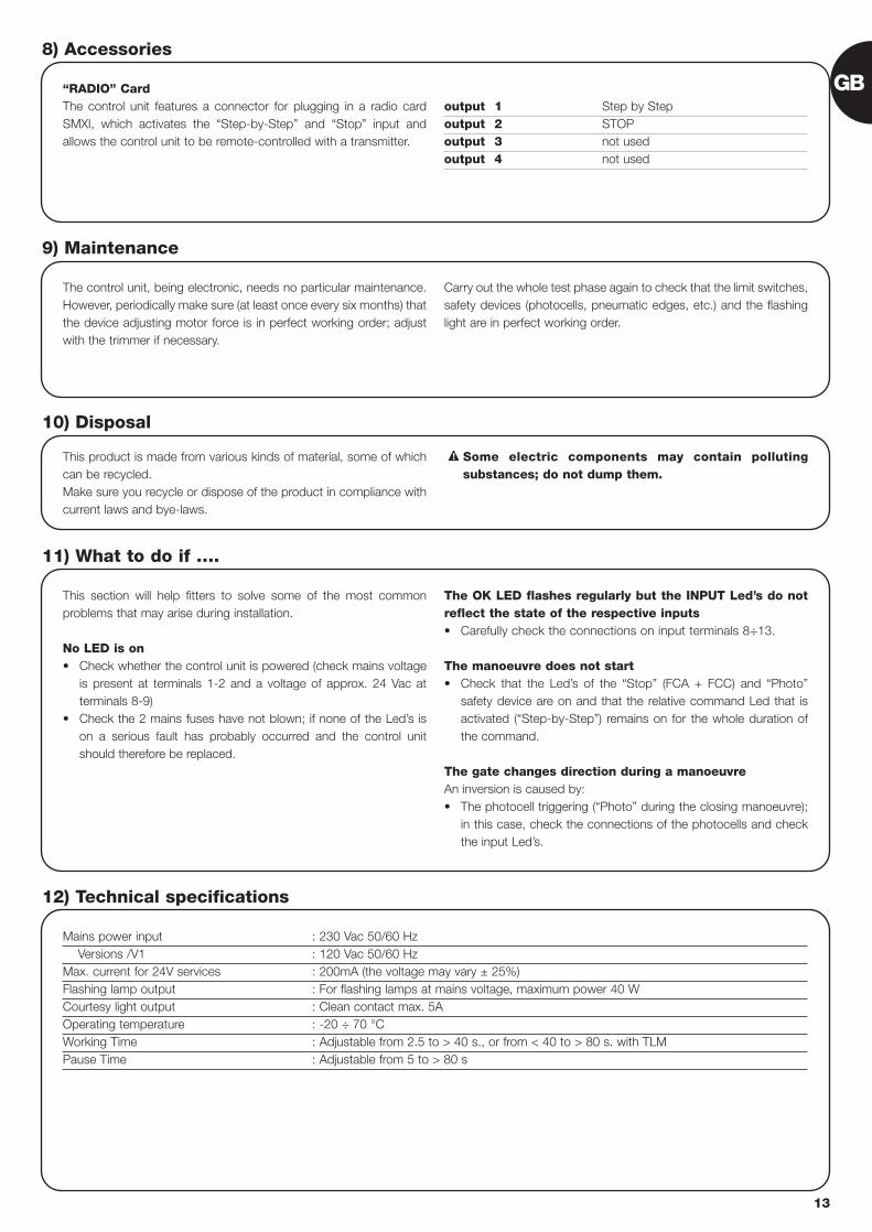
“RADIO” CardThe control unit features a connector for plugging in a radio cardSMXI, which activates the “Step-by-Step” and “Stop” input andallows the control unit to be remote-controlled with a transmitter.
output 1 Step by Stepoutput 2 STOPoutput 3 not usedoutput 4 not used
8) Accessories
The control unit, being electronic, needs no particular maintenance.However, periodically make sure (at least once every six months) thatthe device adjusting motor force is in perfect working order; adjustwith the trimmer if necessary.
Carry out the whole test phase again to check that the limit switches,safety devices (photocells, pneumatic edges, etc.) and the flashinglight are in perfect working order.
9) Maintenance
This product is made from various kinds of material, some of whichcan be recycled.Make sure you recycle or dispose of the product in compliance withcurrent laws and bye-laws.
Some electric components may contain pollutingsubstances; do not dump them.
!
10) Disposal
This section will help fitters to solve some of the most commonproblems that may arise during installation.
No LED is on• Check whether the control unit is powered (check mains voltage
is present at terminals 1-2 and a voltage of approx. 24 Vac atterminals 8-9)
• Check the 2 mains fuses have not blown; if none of the Led’s ison a serious fault has probably occurred and the control unitshould therefore be replaced.
The OK LED flashes regularly but the INPUT Led’s do notreflect the state of the respective inputs• Carefully check the connections on input terminals 8÷13.
The manoeuvre does not start• Check that the Led’s of the “Stop” (FCA + FCC) and “Photo”
safety device are on and that the relative command Led that isactivated (“Step-by-Step”) remains on for the whole duration ofthe command.
The gate changes direction during a manoeuvreAn inversion is caused by:• The photocell triggering (“Photo” during the closing manoeuvre);
in this case, check the connections of the photocells and checkthe input Led’s.
11) What to do if ….
Mains power input : 230 Vac 50/60 HzVersions /V1 : 120 Vac 50/60 Hz
Max. current for 24V services : 200mA (the voltage may vary ± 25%)Flashing lamp output : For flashing lamps at mains voltage, maximum power 40 WCourtesy light output : Clean contact max. 5AOperating temperature : -20 ÷ 70 °CWorking Time : Adjustable from 2.5 to > 40 s., or from < 40 to > 80 s. with TLMPause Time : Adjustable from 5 to > 80 s
12) Technical specifications
GB
13

smxi radio receiver
Description of the product
The special thing about this type of radio receiver is that therecognition code is different for each transmitter (it also changesevery time it is used).Therefore, in order to allow the receiver to recognise a determinedtransmitter, the recognition code must be memorised. This operationmust repeated for each transmitter required to communicate with thecontrol unit.
Up to a maximum of 256 transmitters can be memorised in the receiver.
No one transmitter can be cancelled; all the codes must be deleted.
During the transmitter code memorisation phase, one of theseoptions may be chosen:
Mode I. Each transmitter button activates the corresponding outputin the receiver, that is, button 1 activates output 1, button 2 activatesoutput 2, and so on. In this case there is a single memorisation phasefor each transmitter; during this phase, it doesn’t matter which buttonis pressed and just one memory sector is occupied.Mode II. Each transmitter button can be associated with a particularoutput in the receiver, e.g., button 1 activates output 2, button 2activates output 1, and so on. In this case, the transmitter must bememorised, pressing the required button, for each output to activate.Naturally, each button can activate just one output while the sameoutput can be activated by more than one button. One memorysection is occupied for each button.
Installing the aerial
The receiver requires an ABF or ABFKIT type aerial to work properly;without an aerial the range is limited to just a few metres. The aerialmust be installed as high as possible; if there are metal or reinforcedconcrete structures nearby you can install the aerial on top. If thecable supplied with the aerial is too short, use a coaxial cable with 50-Ohm impedance (e.g. low dispersion RG58), the cable must be nolonger than 10 m.
If the aerial is installed in a place that is not connected to earth(masonry structures), the braid’s terminal can be earthed to provide alarger range of action. The earth point must, of course, be local andof good quality. If an ABF or ABFKIT aerial cannot be installed, youcan get quite good results using the length of wire supplied with thereceiver as the aerial, laying it flat.
14
AB
Memorising a remote control
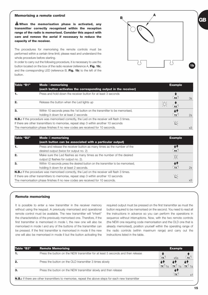
When the memorisation phase is activated, anytransmitter correctly recognised within the receptionrange of the radio is memorised. Consider this aspect withcare and remove the aerial if necessary to reduce thecapacity of the receiver.
The procedures for memorising the remote controls must beperformed within a certain time limit; please read and understand thewhole procedure before starting. In order to carry out the following procedure, it is necessary to use thebutton located on the box of the radio receiver (reference A, Fig. 1b),and the corresponding LED (reference B, Fig. 1b) to the left of thebutton.
!
3s
2s
x3
2s
x3
1. Press and hold down the receiver button for at least 3 seconds
2. Release the button when the Led lights up
3. Within 10 seconds press the 1st button on the transmitter to be memorised, holding it down for at least 2 seconds
N.B.: If the procedure was memorised correctly, the Led on the receiver will flash 3 times.If there are other transmitters to memorise, repeat step 3 within another 10 secondsThe memorisation phase finishes if no new codes are received for 10 seconds.
Table “B1” Mode I memorising Example(each button activates the corresponding output in the receiver)
1. Press and release the receiver button as many times as the number of the desired output (twice for output no. 2)
2. Make sure the Led flashes as many times as the number of the desired output (2 flashes for output no. 2).
3. Within 10 seconds press the desired button on the transmitter to be memorised, holding it down for at least 2 seconds.
N.B.: If the procedure was memorised correctly, the Led on the receiver will flash 3 times.If there are other transmitters to memorise, repeat step 3 within another 10 secondsThe memorisation phase finishes if no new codes are received for 10 seconds.
Table “B2” Mode II memorising Example(each button can be associated with a particular output)
RX
RX
TX
TX
RX
1b
x5s
1s 1s 1s
x1
1. Press the button on the NEW transmitter for at least 5 seconds and then release
2. Press the button on the OLD transmitter 3 times slowly
3. Press the button on the NEW transmitter slowly and then release
N.B.: If there are other transmitters to memorise, repeat the above steps for each new transmitter
Table “B3” Remote Memorising Example
TX
TX TX TX
TX
TX
Remote memorising
It is possible to enter a new transmitter in the receiver memorywithout using the keypad. A previously memorised and operationalremote control must be available. The new transmitter will “inherit”the characteristics of the previously memorised one. Therefore, if thefirst transmitter is memorised in mode I, the new one will also bememorised in mode I and any of the buttons of the transmitter canbe pressed. If the first transmitter is memorised in mode II the newone will also be memorised in mode II but the button activating the
required output must be pressed on the first transmitter as must thebutton required to be memorised on the second. You need to read allthe instructions in advance so you can perform the operations insequence without interruptions. Now, with the two remote controls(the NEW one requiring code memorisation and the OLD one that isalready memorised), position yourself within the operating range ofthe radio controls (within maximum range) and carry out theinstructions listed in the table.
GB
15
16
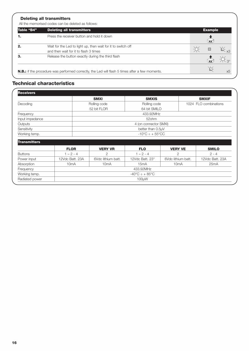
FLOR VERY VR FLO VERY VE SMILOButtons 1 – 2 - 4 2 1 – 2 - 4 2 2 - 4Power input 12Vdc Batt. 23A 6Vdc lithium batt. 12Vdc Batt. 23° 6Vdc lithium batt. 12Vdc Batt. 23AAbsorption 10mA 10mA 15mA 10mA 25mAFrequency 433.92MHzWorking temp. -40°C ÷ + 85°CRadiated power 100µW
Deleting all transmittersAll the memorised codes can be deleted as follows:
x3
3°
x5
1. Press the receiver button and hold it down
2. Wait for the Led to light up, then wait for it to switch off and then wait for it to flash 3 times
3. Release the button exactly during the third flash
N.B.: if the procedure was performed correctly, the Led will flash 5 times after a few moments.
Receivers
Transmitters
Table “B4” Deleting all transmitters Example
RX
RX
SMXI SMXIS SMXIFDecoding Rolling code Rolling code 1024 FLO combinations
52 bit FLOR 64 bit SMILO Frequency 433.92MHzInput impedance 52ohmOutputs 4 (on connector SMXI)Sensitivity better than 0.5µVWorking temp. -10°C ÷ + 55°CC
Technical characteristics
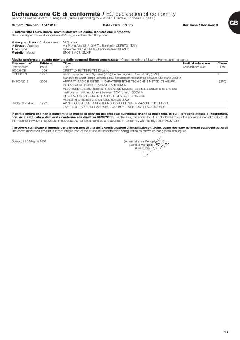
Dichiarazione CE di conformità / EC declaration of conformity(secondo Direttiva 98/37/EC, Allegato II, parte B) (according to 98/37/EC Directive, Enclosure II, part B)
Numero /Number : 151/SMXI Data / Date: 5/2002 Revisione / Revision: 0
Il sottoscritto Lauro Buoro, Amministratore Delegato, dichiara che il prodotto:The undersigned Lauro Buoro, General Manager, declares that the product:
Nome produttore / Producer name: NICE s.p.a.Indirizzo / Address: Via Pezza Alta 13, 31046 Z.I. Rustignè –ODERZO- ITALYTipo / Type: Ricevitore radio 433MHz / Radio receiver 433MHzModello / Model: SMXI, SMXIS, SMXIF
Risulta conforme a quanto previsto dalle seguenti Norme armonizzate / Complies with the following Harmonised standardsRiferimento n° Edizione Titolo Livello di valutazione ClasseReference n° Issue Title Assessment level Class1999/5/CE 1999 DIRETTIVA R&TTE/R&TTE DirectiveETS300683 1997 Radio Equipment and Systems (RES);Electromagnetic Compatibility (EMC) II
standard for Short Range Devices (SRD) operating on frequencies between 9KHz and 25GHzEN300220-3 2000 APPARATI RADIO E SISTEMI - CARATTERISTICHE TECNICHE E METODI DI MISURA I (LPD)
PER APPARATI RADIO TRA 25MHz A 1000MHzRadio Equipment and Sistems- Short Range Devices-Technical characteristics and test methods for radio equipment between 25MHz and 1000MHzREGOLAZIONE ALL’USO DEI DISPOSITIVI A CORTO RAGGIORegolating to the use of short range devices (SRD)
EN60950 2nd ed. 1992 APPARECCHIATURE PERLA TECNOLOGIA DELL’INFORMAZIONE. SICUREZZA. +A1: 1993 + A2: 1993 + A3: 1995 + A4: 1997 + A11: 1997 + EN41003/1993.
Inoltre dichiara che non è consentita la messa in servizio del prodotto suindicato finché la macchina, in cui il prodotto stesso è incorporato,non sia identificata e dichiarata conforme alla direttiva 98/37/CEE/ He declares, moreover, that it is not allowed to use the above mentioned product untilthe machine, in which this product is incorporated, has been identified and declared in conformity with the regulation 98/37/CEE.
Il prodotto suindicato si intende parte integrante di una delle configurazioni di installazione tipiche, come riportato nei nostri cataloghi generaliThe above mentioned product is meant integral part of the of one of the installation configuration as shown on our general catalogues
Oderzo, li 13 Maggio 2002 (Amministratore Delegato)(General Manager)
Lauro Buoro
17
GB
18
centrale comandomotoriduttorirobo, thor
Avvertenze:
Il presente manuale è destinato solamente al personaletecnico qualificato per l'installazione. Nessuna informazionecontenuta nel presente fascicolo può essere consideratad’interesse per l'utilizzatore finale!La centrale è destinata al comando di attuatori elettromec-canici per l’automazione di cancelli, ogni altro uso èimproprio e quindi vietato dalle normative vigenti.Si consiglia di leggere attentamente tutte le istruzioni, almeno una volta,prima di procedere con l’installazione.
!
Indice: pag.
1 Descrizione del prodotto 19
2 Installazione 192.1 Impianto tipico 192.2 Collegamenti elettrici 202.2.1 Schema elettrico 202.2.2 Descrizione dei collegamenti 202.2.3 Fototest 212.2.4 Verifica dei collegamenti 22
3 Regolazioni 22
4 Collaudo 23
5 Modi di funzionamento 24
pag.
6 Funzioni programmabili 246.1 Descrizione delle funzioni 25
7 Come fare per... 26
8 Accessori Opzionali 27
9 Manutenzione 27
10 Smaltimento 27
11 Cosa fare se… 27
12 Caratteristiche tecniche 27
I
19
I
1) Descrizione del prodotto:
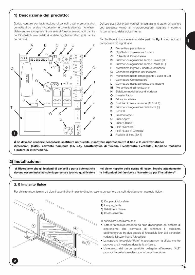
Questa centrale per l’automazione di cancelli e porte automatiche,permette di comandare motoriduttori in corrente alternata monofase.Nella centrale sono presenti una serie di funzioni selezionabili tramitedei Dip-Switch (mini selettori) e delle regolazioni effettuabili tramitedei Trimmer.
Dei Led posti vicino agli ingressi ne segnalano lo stato; un ulterioreLed presente vicino al microprocessore, segnala il correttofunzionamento della logica interna.
Per facilitare il riconoscimento delle parti, in fig.1 sono indicati icomponenti più significativi.
OK
BA C
R
D E F
G
H
I
L
M
P
S
Z
O
T
U V
Q
N
W X
Morsettiera per antennaDip-Switch di selezione funzioniPulsante di Passo PassoTrimmer di regolazione Tempo Lavoro (TL)Trimmer di regolazione Tempo Pausa (TP)Morsettiera Ingressi / Uscite di comandoConnettore ingresso dei finecorsaMorsettiera uscita lampeggiante / Luce di Cor.Connettore CondensatoreConnettore uscita alimentazione motoreMorsettiera di alimentazioneSelettore modalità luce di cortesiaInnesto RadioMicroprocessoreFusibile di bassa tensione (315mA T)Trimmer di regolazione della forza (F)Led OKTrasformatoreTriac “Apre”Triac “Chiude”Relè “Comune”Relè “Luce di Cortesia”Fusibile di linea (5A T)
ABCDEFGHILMNOPQRSTUVWXZ1
2.1) Impianto tipico
Per chiarire alcuni termini ed alcuni aspetti di un impianto di automazione per porte o cancelli, riportiamo un esempio tipico.
Ricordiamo che gli impianti di cancelli e porte automatichedevono essere installati solo da personale tecnico qualificato e
nel pieno rispetto delle norme di legge. Seguire attentamentele indicazioni del fascicolo : “Avvertenze per l’installatore”.
!
2) Installazione:
2
4
3
FOTO
2
1
1) Coppia di fotocellule2) Lampeggiante3) Selettore a chiave4) Bordo sensibile
In particolare ricordiamo che:• Tutte le fotocellule prodotte da Nice dispongono del sistema di
sincronismo che permette di eliminare il problemadell’interferenza tra due coppie di fotocellule (per altri particolarivedere le istruzioni delle fotocellule)
• La coppia di fotocellule “Foto” in apertura non ha effetto mentreprovoca una inversione durante la chiusura.
• L’intervento del bordo sensibile collegato all’ingresso “ALT”provoca l’arresto immediato e una breve inversione.
Se dovesse rendersi necessario sostituire un fusibile, rispettare rigorosamente il tipo e le caratteristiche: Dimensioni (5x20), corrente nominale (es. 5A), caratteristica di fusione (T=ritardata, F=rapida), tensione massima e potere di interruzione.
!
20
2.2.1) Schema elettrico
DA RETE
ALIMENTAZIONE
P.P.
FOTO
FCA
FCC
FOTOTEST
24 Vac
0 Vac
8
GND
LUXMax 40W
ANT.
FOTO
P.P.
ALT11
10
9
12
13
CORTESIALUCE DI
4
5
6
L
3
1
2
7
N
RADIO
2.2) Collegamenti elettrici
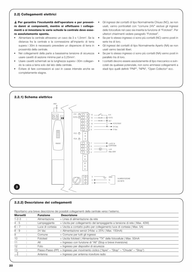
Per garantire l'incolumità dell'operatore e per preveni-re danni ai componenti, mentre si effettuano i collega-menti o si innestano le varie schede la centrale deve esse-re assolutamente spenta.• Alimentare la centrale attraverso un cavo da 3 x 1,5mm2. Se la
distanza fra la centrale e la connessione all'impianto di terrasupera i 30m è necessario prevedere un dispersore di terra inprossimità della centrale.
• Nei collegamenti della parte a bassissima tensione di sicurezzausare cavetti di sezione minima pari a 0,25mm2.
• Usare cavetti schermati se la lunghezza supera i 30m collegan-do la calza a terra solo dal lato della centrale.
• Evitare di fare connessioni ai cavi in casse interrate anche secompletamente stagne.
• Gli ingressi dei contatti di tipo Normalmente Chiuso (NC), se nonusati, vanno ponticellati con “comune 24V” esclusi gli ingressidelle fotocellule nel caso sia inserita la funzione di “Fototest”. Perulteriori chiarimenti vedere paragrafo “Fototest”.
• Se per lo stesso ingresso ci sono più contatti (NC) vanno posti inserie tra di loro.
• Gli ingressi dei contatti di tipo Normalmente Aperto (NA) se nonusati vanno lasciati liberi.
• Se per lo stesso ingresso ci sono più contatti (NA) vanno posti inparallelo tra di loro.
• I contatti devono essere assolutamente di tipo meccanico e svin-colati da qualsiasi potenziale, non sono ammessi collegamenti astadi tipo quelli definiti "PNP", "NPN", "Open Collector" ecc.
!
2.2.2) Descrizione dei collegamenti
Riportiamo una breve descrizione dei possibili collegamenti della centrale verso l’esterno.Morsetti Funzione Descrizione1-2-3 : Alimentazione = Linea di alimentazione da rete4 - 5 : Lampeggiante = Uscita per collegamento del lampeggiante a tensione di rete ( Max. 40W)6 – 7 : Luce di cortesia = Uscita a contatto pulito per collegamento luce di cortesia ( Max. 5A)8 - 9 : 24 Vac = Alimentazione servizi 24Vac ± 25% ( Max. 150mA) 9 : Comune = Comune per tutti gli ingressi10 : Fototest = Uscita fototest ( Alimentazione “TX” delle fotocellule ) Max. 50mA11 : Alt = Ingresso con funzione di “Alt” (Stop e breve inversione)12 : Foto = Ingresso per dispositivi di sicurezza13 : Passo-Passo (PP) = Ingresso per movimento ciclico (“Apre” – “Stop” – “Chiude” – “Stop”)
: Antenna = Ingresso per antenna ricevitore radio
3
I
21
2.2.3) Fototest
Il “Fototest”, aumenta l’affidabilità dei dispositivi di sicurezza;permettendo di raggiungere la “categoria 2” secondo la norma EN 954-1 (ediz. 12/1998) per quanto riguarda l’insieme centrale efotocellule di sicurezza.Ogni volta che viene avviata una manovra vengono controllati idispositivi di sicurezza coinvolti; solo se tutto è a posto la manovraha inizio. Se invece il test non dà esito positivo (fotocellula accecatadal sole, cavi in corto circuito, ecc.) viene individuato il guasto e lamanovra non viene eseguita.Per ottenere la funzione “Fototest” è necessario:• Impostare il Dip-Switch 10 ON • Collegare le fotocellule come in fig. 4a (se si utilizza una sola
coppia di fotocellule) o come in fig. 4b (se si utilizzano 2 coppiedi fotocellule) nei quali l’alimentazione dei trasmettitori dellefotocellule non è presa direttamente dall’uscita dei servizi, ma dal’uscita “Fototest” tra i morsetto (8-10). La corrente massimautilizzabile sull’uscita “Fototest” è di 50mA (2 coppie di TX Nice)
• Alimentare i ricevitori direttamente dall’uscita servizi dellacentrale (morsetti 8-9).
Nel caso in cui si usino 2 coppie di fotocellule che possano interferiretra loro, attivare il sincronismo come descritto nelle istruzioni dellefotocellule.
Se in un secondo momento non si desiderasse più utilizzare la funzione
di Fototest, sarà sufficiente porre in posizione OFF il Dip-Switch 10.
Il test delle fotocellule avviene in questo modo: quando è richiesto unmovimento, in primo luogo viene controllato che tutti i ricevitoriinteressati dal movimento diano il consenso, poi viene spental’alimentazione ai trasmettitori e quindi verificato che tutti i ricevitorisegnalino il fatto togliendo il loro consenso; infine viene riattivatal'alimentazione dei trasmettitori e quindi nuovamente verificato ilconsenso da parte di tutti i ricevitori. Solo se questa sequenza haesito positivo, la manovra verrà avviata.
3 4 5
RX
1 2
9
98
TX
21
98 12
RX
4 5
FOTO
321
TX
FOTO
21
1311 1298 10
RxA
RxB
5421 3
1298
FOTO B
5
RXBTXB
21
810
RXB
4 5321
TXB
FOTO B
21
5421 3
98
FOTO A
59
RXATXA
21
810
4 5
RXA
1311 12
2 31
TXA
FOTO A
1 2
98 10
12 13111098
RX
3 4 51 2
9
912
8
FOTO
1 2
108
RX
3 4 51 2
TX
1 2
FOTO
TX
4a
4b
4c
fig. 4aFoto con collegamento per fototest
fig. 4bFoto A e foto B concollegamento per fototest
fig. 4cFoto con collegamento senza fototest
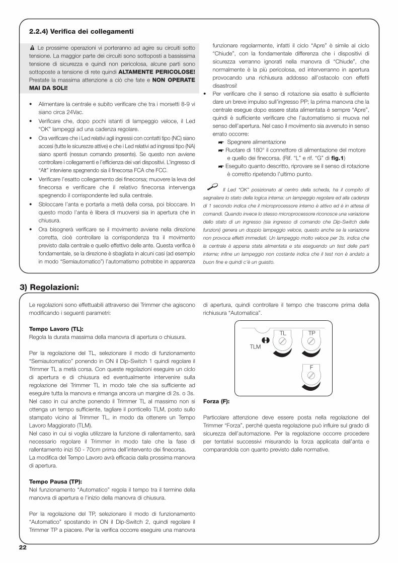
22
2.2.4) Verifica dei collegamenti
Le prossime operazioni vi porteranno ad agire su circuiti sottotensione. La maggior parte dei circuiti sono sottoposti a bassissimatensione di sicurezza e quindi non pericolosa, alcune parti sonosottoposte a tensione di rete quindi ALTAMENTE PERICOLOSE!Prestate la massima attenzione a ciò che fate e NON OPERATEMAI DA SOLI!
• Alimentare la centrale e subito verificare che tra i morsetti 8-9 visiano circa 24Vac.
• Verificare che, dopo pochi istanti di lampeggio veloce, il Led“OK” lampeggi ad una cadenza regolare.
• Ora verificare che i Led relativi agli ingressi con contatti tipo (NC) sianoaccesi (tutte le sicurezze attive) e che i Led relativi ad ingressi tipo (NA)siano spenti (nessun comando presente). Se questo non avvienecontrollare i collegamenti e l’efficienza dei vari dispositivi. L’ingresso di“Alt” interviene spegnendo sia il finecorsa FCA che FCC.
• Verificare l’esatto collegamento dei finecorsa; muovere la leva delfinecorsa e verificare che il relativo finecorsa intervengaspegnendo il corrispondente led sulla centrale.
• Sbloccare l’anta e portarla a metà della corsa, poi bloccare. Inquesto modo l’anta è libera di muoversi sia in apertura che inchiusura.
• Ora bisognerà verificare se il movimento avviene nella direzionecorretta, cioè controllare la corrispondenza tra il movimentoprevisto dalla centrale e quello effettivo delle ante. Questa verifica èfondamentale, se la direzione è sbagliata in alcuni casi (ad esempioin modo “Semiautomatico”) l’automatismo potrebbe in apparenza
funzionare regolarmente, infatti il ciclo “Apre” è simile al ciclo“Chiude”, con la fondamentale differenza che i dispositivi disicurezza verranno ignorati nella manovra di “Chiude”, chenormalmente è la più pericolosa, ed interverranno in aperturaprovocando una richiusura addosso all’ostacolo con effettidisastrosi!
• Per verificare che il senso di rotazione sia esatto è sufficientedare un breve impulso sull’ingresso PP; la prima manovra che lacentrale esegue dopo essere stata alimentata è sempre “Apre”,quindi è sufficiente verificare che l’automatismo si muova nelsenso dell’apertura. Nel caso il movimento sia avvenuto in sensoerrato occorre:
� Spegnere alimentazione� Ruotare di 180° il connettore di alimentazione del motore
e quello dei finecorsa. (Rif. “L” e rif. “G” di fig.1)� Eseguito quanto descritto, riprovare se il senso di rotazione
è corretto ripetendo l’ultimo punto.
Il Led “OK” posizionato al centro della scheda, ha il compito di
segnalare lo stato della logica interna: un lampeggio regolare ed alla cadenza
di 1 secondo indica che il microprocessore interno è attivo ed è in attesa di
comandi. Quando invece lo stesso microprocessore riconosce una variazione
dello stato di un ingresso (sia ingresso di comando che Dip-Switch delle
funzioni) genera un doppio lampeggio veloce, questo anche se la variazione
non provoca effetti immediati. Un lampeggio molto veloce per 3s. indica che
la centrale è appena stata alimentata e sta eseguendo un test delle parti
interne; infine un lampeggio non costante indica che il test non è andato a
buon fine e quindi c’è un guasto.
!
Le regolazioni sono effettuabili attraverso dei Trimmer che agisconomodificando i seguenti parametri:
Tempo Lavoro (TL): Regola la durata massima della manovra di apertura o chiusura.
Per la regolazione del TL, selezionare il modo di funzionamento“Semiautomatico” ponendo in ON il Dip-Switch 1 quindi regolare ilTrimmer TL a metà corsa. Con queste regolazioni eseguire un ciclodi apertura e di chiusura ed eventualmente intervenire sullaregolazione del Trimmer TL in modo tale che sia sufficiente adeseguire tutta la manovra e rimanga ancora un margine di 2s. o 3s.Nel caso in cui anche ponendo il Trimmer TL al massimo non siottenga un tempo sufficiente, tagliare il ponticello TLM, posto sullostampato vicino al Trimmer TL, in modo da ottenere un TempoLavoro Maggiorato (TLM).Nel caso in cui si voglia utilizzare la funzione di rallentamento, sarànecessario regolare il Trimmer in modo tale che la fase dirallentamento inizi 50 - 70cm prima dell’intervento dei finecorsa.La modifica del Tempo Lavoro avrà efficacia dalla prossima manovradi apertura.
Tempo Pausa (TP):Nel funzionamento “Automatico” regola il tempo tra il termine dellamanovra di apertura e l’inizio della manovra di chiusura.
Per la regolazione del TP, selezionare il modo di funzionamento“Automatico” spostando in ON il Dip-Switch 2, quindi regolare ilTrimmer TP a piacere. Per la verifica occorre eseguire una manovra
di apertura, quindi controllare il tempo che trascorre prima dellarichiusura “Automatica”.
Forza (F):
Particolare attenzione deve essere posta nella regolazione delTrimmer “Forza”, perché questa regolazione può influire sul grado disicurezza dell’automazione. Per la regolazione occorre procedereper tentativi successivi misurando la forza applicata dall’anta ecomparandola con quanto previsto dalle normative.
3) Regolazioni:
F
TL TP
TLM
I
23
Terminate le verifiche e le regolazioni è possibile passare al collaudo dell’impianto.
Il collaudo dell’automazione deve essere eseguito da personale qualificato ed esperto che dovrà farsi carico distabilire le prove previste in funzione del rischio presente.
Il collaudo è la parte più importante di tutta la realizzazione dell’automazione. Ogni singolo componente, ad esempio motoriduttore, arrestodi emergenza, fotocellule ecc. può richiedere una specifica fase di collaudo e per questo si consiglia di seguire le procedure riportate neirispettivi manuali di istruzioni.
Per il collaudo della centrale eseguire la seguente sequenza di operazioni:
1. Selezione funzioni: • Impostare ON il Dip-Switch 1 (Funzionamento “Semiautomatico”)• Impostare OFF tutti gli altri Dip-Switch
2. Premere il tasto di comando “Passo Passo” e verificare che:• Inizi una manovra di apertura• Si attivi il lampeggiante• Il movimento si arresti al raggiungimento del finecorsa di apertura FCA
3. Premere nuovamente il tasto di “Passo Passo” e verificare che:• Inizi una manovra di chiusura• Si attivi il lampeggiante• Il movimento si arresti al raggiungimento del finecorsa di chiusura FCC
4. Far partire una manovra di apertura e verificare che durante la manovra, l’intervento di un dispositivo:• Collegato all’ingresso di “Alt”, provochi l’arresto immediato del movimento e una breve inversione• Collegato all’ingresso di “Foto”, non abbia nessun effetto
5. Far partire una manovra di chiusura e verificare che durante la manovra, l’intervento di un dispositivo:• Collegato all’ingresso di “Alt”, provochi l’arresto immediato del movimento e una breve inversione• Collegato all’ingresso di “Foto”, provochi la fermata e l’inversione della manovra
6. Premere il tasto di “Passo Passo” e verificare che ogni attivazione dell’ingresso provochi un passo nella sequenza:• “Apre” – “Stop” – “Chiude” – “Stop”
7. Se si utilizza la funzione di “Fototest” verificare l’efficienza del test:• Interrompere la fotocellula “Foto”, quindi far partire una manovra e verificare che questa non venga eseguita• Cortocircuitare il contatto della fotocellula “Foto” quindi far partire una manovra e verificare che questa non venga eseguita.
8. Eseguire le prove per la rilevazione delle “Forze di impatto” come previsto dalla norma EN 12445.
Se al termine del collaudo vengono attivate ulteriori funzioni programmabili che possono ridurre la sicurezza dell’impianto, è necessarioeffettuare un collaudo specifico di tali funzioni
!
4) Collaudo
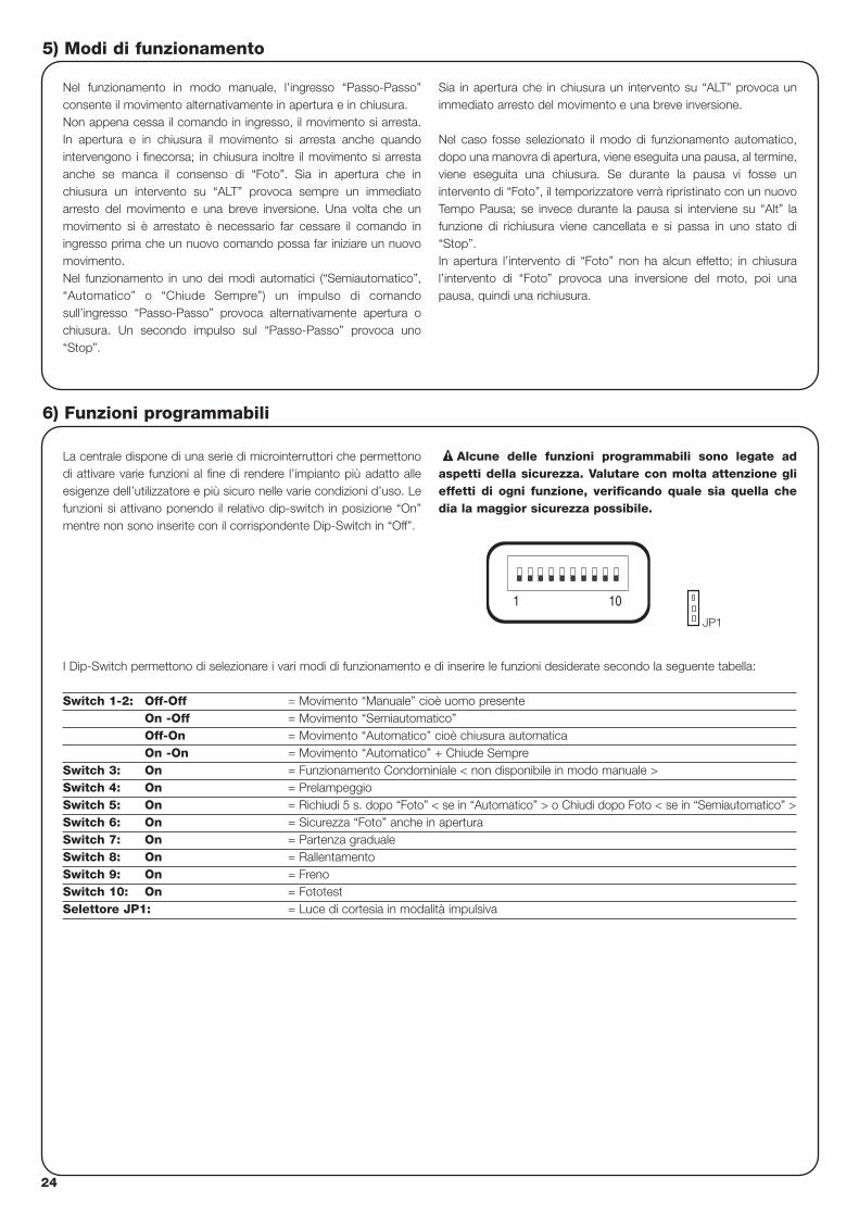
24
5) Modi di funzionamento
Nel funzionamento in modo manuale, l’ingresso “Passo-Passo”consente il movimento alternativamente in apertura e in chiusura. Non appena cessa il comando in ingresso, il movimento si arresta.In apertura e in chiusura il movimento si arresta anche quandointervengono i finecorsa; in chiusura inoltre il movimento si arrestaanche se manca il consenso di “Foto”. Sia in apertura che inchiusura un intervento su “ALT” provoca sempre un immediatoarresto del movimento e una breve inversione. Una volta che unmovimento si è arrestato è necessario far cessare il comando iningresso prima che un nuovo comando possa far iniziare un nuovomovimento.Nel funzionamento in uno dei modi automatici (“Semiautomatico”,“Automatico” o “Chiude Sempre”) un impulso di comandosull’ingresso “Passo-Passo” provoca alternativamente apertura ochiusura. Un secondo impulso sul “Passo-Passo” provoca uno“Stop”.
Sia in apertura che in chiusura un intervento su “ALT” provoca unimmediato arresto del movimento e una breve inversione.
Nel caso fosse selezionato il modo di funzionamento automatico,dopo una manovra di apertura, viene eseguita una pausa, al termine,viene eseguita una chiusura. Se durante la pausa vi fosse unintervento di “Foto”, il temporizzatore verrà ripristinato con un nuovoTempo Pausa; se invece durante la pausa si interviene su “Alt” lafunzione di richiusura viene cancellata e si passa in uno stato di“Stop”.In apertura l’intervento di “Foto” non ha alcun effetto; in chiusural’intervento di “Foto” provoca una inversione del moto, poi unapausa, quindi una richiusura.
La centrale dispone di una serie di microinterruttori che permettonodi attivare varie funzioni al fine di rendere l’impianto più adatto alleesigenze dell’utilizzatore e più sicuro nelle varie condizioni d’uso. Lefunzioni si attivano ponendo il relativo dip-switch in posizione “On”mentre non sono inserite con il corrispondente Dip-Switch in “Off”.
Alcune delle funzioni programmabili sono legate adaspetti della sicurezza. Valutare con molta attenzione glieffetti di ogni funzione, verificando quale sia quella chedia la maggior sicurezza possibile.
!
I Dip-Switch permettono di selezionare i vari modi di funzionamento e di inserire le funzioni desiderate secondo la seguente tabella:
Switch 1-2: Off-Off = Movimento “Manuale” cioè uomo presenteOn -Off = Movimento “Semiautomatico”Off-On = Movimento “Automatico” cioè chiusura automaticaOn -On = Movimento “Automatico” + Chiude Sempre
Switch 3: On = Funzionamento Condominiale < non disponibile in modo manuale >Switch 4: On = PrelampeggioSwitch 5: On = Richiudi 5 s. dopo “Foto” < se in “Automatico” > o Chiudi dopo Foto < se in “Semiautomatico” >Switch 6: On = Sicurezza “Foto” anche in aperturaSwitch 7: On = Partenza gradualeSwitch 8: On = RallentamentoSwitch 9: On = FrenoSwitch 10: On = FototestSelettore JP1: = Luce di cortesia in modalità impulsiva
6) Funzioni programmabili
101
JP1
I
25
6.1) Descrizione delle funzioni
Riportiamo ora una breve descrizione delle funzioni che si possono inserire portando in “On” il relativo Dip-Switch
Switch 1-2: Off-Off = Movimento “Manuale” (uomo presente)On-Off = Movimento “Semiautomatico”Off-On = Movimento “Automatico” (chiusura automatica)On-On = Movimento “Automatico” + “Chiude Sempre”
Nel funzionamento “Manuale” il movimento viene eseguito solo fino alla presenza del comando (tasto premuto).In “Semiautomatico” basta un impulso di comando per far eseguire tutto il movimento fino allo scadere del Tempo Lavoro o alraggiungimento del finecorsa. Nel funzionamento in modo “Automatico”, dopo una apertura viene eseguita una pausa, quindi la chiusuraavviene automaticamente.La funzione “Chiude Sempre” interviene dopo una mancanza di alimentazione; se viene rilevato il cancello aperto si avvia automaticamenteuna manovra di chiusura preceduta da 5 secondi di prelampeggio.
Switch 3: On = Funzionamento Condominiale (non disponibile in modo manuale)Nel funzionamento condominiale, una volta avviato un movimento in apertura la manovra non può essere interrotta da altri impulsi dicomando su “Passo-Passo” fino alla fine del movimento in apertura.Nel movimento in chiusura un nuovo impulso di comando provoca l’arresto e l’inversione del movimento in apertura.
Switch 4: On = PrelampeggioAll’impulso di comando viene prima attivato il lampeggiante poi, dopo 5s. (2s. se in “Manuale”), inizia il movimento.
Switch 5: On = Richiudi 5 s. dopo Foto < se in “Automatico” > o Chiudi dopo Foto < se in “Semiautomatico” >Questa funzione, se in “Automatico” permette di tenere il cancello aperto solo per il tempo necessario al transito, infatti al terminedell’intervento di “Foto” la manovra si arresta. Dopo 5s. partirà automaticamente una manovra di chiusura. Se in “Semiautomatico”, unintervento di “Foto” nella manovra di chiusura attiva la chiusura automatica con il Tempo Pausa regolato.
Switch 6: On = Sicurezza “Foto” anche in aperturaNormalmente la sicurezza “Foto” è attiva solo nella manovra di chiusura, se lo Dip-Switch 6 viene posto su "On" l'intervento del dispositivodi sicurezza provoca una interruzione del movimento anche in apertura.Se in “Semiautomatico” o “Automatico” si avrà la ripresa del moto in apertura subito dopo il disimpegno.
Switch 7: On = Partenza gradualeEsegue l’inizio del movimento in modo graduale evitando gli indesiderati scossoni dell’automazione
Switch 8: On = Rallentamento Il rallentamento consiste in una riduzione della velocità al 30% della velocità nominale in modo da ridurre la forza di impatto nelle zone diapertura e chiusura del cancello.
Una volta attivata la funzione di rallentamento, sarà necessario agire sul Trimmer Tempo Lavoro (TL) in quanto, l’inizio del rallentamento è legato al tempo lavoro impostato. Quindi regolare il tempo Lavoro affinchè il rallentamento inizi circa 50-70 cm prima dell’intervento dei finecorsa.
La funzione di rallentamento oltre che diminuire la velocità dell’automazione riduce del 70% la coppia del motore.
In automazioni che richiedono una coppia elevata, questa riduzione potrebbe provocare l’arresto immediato del motore.
Switch 9: On = FrenoAl termine del movimento viene eseguita una procedura di freno al motore, inizialmente blanda poi più incisiva in modo da fermare il cancellovelocemente ma senza scossoni.
Switch 10: On = FototestQuesta funzione permette di eseguire ad ogni inizio manovra un controllo dell’efficienza delle fotocellule. Vedere capitolo “Fototest”.
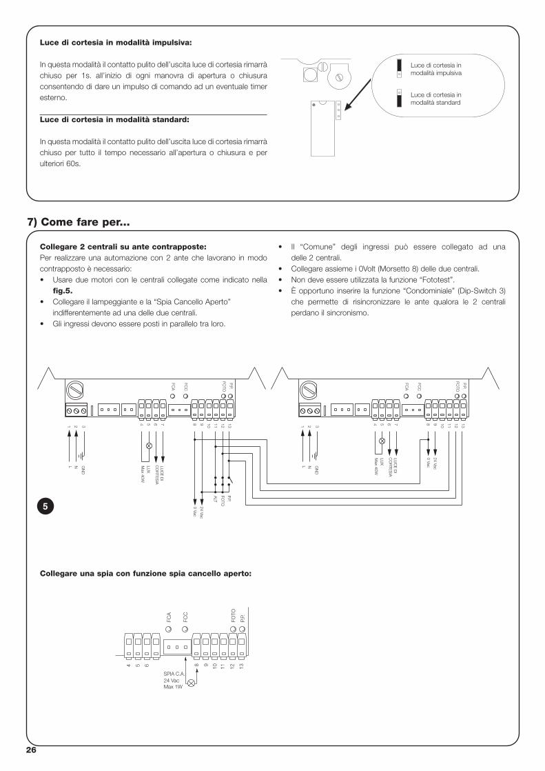
26
Collegare 2 centrali su ante contrapposte:Per realizzare una automazione con 2 ante che lavorano in modocontrapposto è necessario:• Usare due motori con le centrali collegate come indicato nella
fig.5.• Collegare il lampeggiante e la “Spia Cancello Aperto”
indifferentemente ad una delle due centrali.• Gli ingressi devono essere posti in parallelo tra loro.
• Il “Comune” degli ingressi può essere collegato ad una delle 2 centrali.
• Collegare assieme i 0Volt (Morsetto 8) delle due centrali.• Non deve essere utilizzata la funzione “Fototest”.• È opportuno inserire la funzione “Condominiale” (Dip-Switch 3)
che permette di risincronizzare le ante qualora le 2 centraliperdano il sincronismo.
7) Come fare per...
N
7
21 3
L
654
LUC
E D
IC
OR
TES
IA
13129 10 11A
LT
P.P.
FOTO
Max 40W
LUX
GN
D
8
0 Vac
24 Vac
FCC
FCA
FOTO
P.P.
11
0 Vac
24 Vac
CO
RTE
SIA
Max 40W
GN
D3
NL
1 2
LUX
LUC
E D
I
54 76 8 9 10
FCA
FCC
12 13FO
TO
P.P.
5
Luce di cortesia in modalità impulsiva:
In questa modalità il contatto pulito dell’uscita luce di cortesia rimarràchiuso per 1s. all’inizio di ogni manovra di apertura o chiusuraconsentendo di dare un impulso di comando ad un eventuale timeresterno.
Luce di cortesia in modalità standard:
In questa modalità il contatto pulito dell’uscita luce di cortesia rimarràchiuso per tutto il tempo necessario all’apertura o chiusura e perulteriori 60s.
Luce di cortesia inmodalità impulsiva
Luce di cortesia inmodalità standard
FCC
FCA
P.P.
54 6 1198 10 12 13
24 VacSPIA C.A.
Max 1W
FOTO
Collegare una spia con funzione spia cancello aperto:
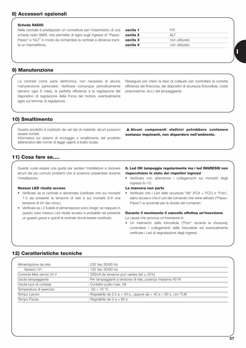
I
27
Scheda RADIONelle centrale è predisposto un connettore per l’inserimento di unascheda radio SMXI, che permette di agire sugli ingressi di “Passo-Passo” e “ALT” in modo da comandare la centrale a distanza trami-te un trasmettitore.
uscita 1 P.P.uscita 2 ALTuscita 3 non utilizzatouscita 4 non utilizzato
8) Accessori opzionali
La centrale come parte elettronica, non necessita di alcunamanutenzione particolare. Verificare comunque periodicamente(almeno ogni 6 mesi), la perfetta efficienza e la regolazione deldispositivo di regolazione della Forza del motore, eventualmenteagire sul trimmer di regolazione.
Rieseguire per intero la fase di collaudo per controllare la correttaefficienza dei finecorsa, dei dispositivi di sicurezza (fotocellule, costepneumatiche, ecc.) del lampeggiante.
9) Manutenzione
Questo prodotto è costituito da vari tipi di materiali, alcuni possonoessere riciclati.Informatevi sui sistemi di riciclaggio o smaltimento del prodottoattenendovi alle norme di legge vigenti a livello locale.
Alcuni componenti elettrici potrebbero conteneresostanze inquinanti, non disperdere nell’ambiente.
!
10) Smaltimento
Questa vuole essere una guida per aiutare l’installatore a risolverealcuni dei più comuni problemi che si possono presentare durantel’installazione.
Nessun LED risulta acceso• Verificare se la centrale è alimentata (verificare che sui morsetti
1-2 sia presente la tensione di rete e sui morsetti 8-9 unatensione di 24 Vac circa.)
• Verificare se i 2 fusibili di alimentazione sono integri: se neppure inquesto caso nessun Led risulta acceso è probabile sia presenteun guasto grave e quindi la centrale dovrà essere sostituita.
IL Led OK lampeggia regolarmente ma i led INGRESSI nonrispecchiano lo stato dei rispettivi ingressi• Verificare con attenzione i collegamenti sui morsetti degli
ingressi 8÷13.La manovra non parte• Verificare che i Led delle sicurezze “Alt” (FCA + FCC) e “Foto”,
siano accesi e che il Led del comando che viene attivato (“Passo-Passo”) si accenda per la durata del comando.
Durante il movimento il cancello effettua un’inversioneLa causa che provoca un’inversione è: • Un intervento della fotocellula (“Foto” durante la chiusura);
controllare i collegamenti delle fotocellule ed eventualmenteverificare i Led di segnalazione degli ingressi.
11) Cosa fare se….
Alimentazione da rete : 230 Vac 50/60 HzVersioni /V1 : 120 Vac 50/60 Hz
Corrente Max servizi 24 V : 200mA (la tensione può variare del ± 25%)Uscita lampeggiante : Per lampeggianti a tensione di rete, potenza massima 40 WUscita luce di cortesia : Contatto pulito max. 5ATemperatura di esercizio : -20 ÷ 70 °CTempo Lavoro : Regolabile da 2.5 a > 40 s., oppure da < 40 a > 80 s. con TLMTempo Pausa : Regolabile da 5 a > 80 s.
12) Caratteristiche tecniche
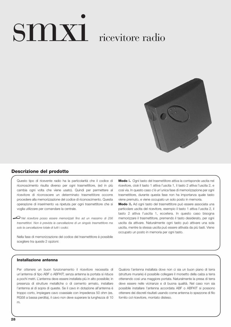
28
smxi ricevitore radio
Descrizione del prodotto
Questo tipo di ricevente radio ha la particolarità che il codice diriconoscimento risulta diverso per ogni trasmettitore, (ed in piùcambia ogni volta che viene usato). Quindi per permettere alricevitore di riconoscere un determinato trasmettitore occorreprocedere alla memorizzazione del codice di riconoscimento. Questaoperazione di inserimento va ripetuta per ogni trasmettitore che sivoglia utilizzare per comandare la centrale.
Nel ricevitore posso essere memorizzati fino ad un massimo di 256
trasmettitori. Non è prevista la cancellazione di un singolo trasmettitore ma
solo la cancellazione totale di tutti i codici.
Nella fase di memorizzazione del codice del trasmettitore è possibilescegliere tra queste 2 opzioni:
Modo I. Ogni tasto del trasmettitore attiva la corrisponde uscita nelricevitore, cioè il tasto 1 attiva l’uscita 1, il tasto 2 attiva l’uscita 2, ecosì via. In questo caso c’è un’unica fase di memorizzazione per ognitrasmettitore, durante questa fase non ha importanza quale tastoviene premuto, e viene occupato un solo posto in memoria.Modo II. Ad ogni tasto del trasmettitore può essere associata unaparticolare uscita del ricevitore, esempio il tasto 1 attiva l’uscita 2, iltasto 2 attiva l’uscita 1, eccetera. In questo caso bisognamemorizzare il trasmettitore, premendo il tasto desiderato, per ogniuscita da attivare. Naturalmente ogni tasto può attivare una solauscita, mentre la stessa uscita può essere attivata da più tasti. Vieneoccupato un posto in memoria per ogni tasto.
Installazione antenna
Per ottenere un buon funzionamento il ricevitore necessita diun’antenna di tipo ABF o ABFKIT; senza antenna la portata si riducea pochi metri. L’antenna deve essere installata più in alto possibile; inpresenza di strutture metalliche o di cemento armato, installarel’antenna al di sopra di queste. Se il cavo in dotazione all’antenna ètroppo corto, impiegare cavo coassiale con impedenza 50 ohm (es.RG58 a bassa perdita), il cavo non deve superare la lunghezza di 10m.
Qualora l’antenna installata dove non ci sia un buon piano di terra(strutture murarie) è possibile collegare il morsetto della calza a terraottenendo così una maggiore portata. Naturalmente la presa di terradeve essere nelle vicinanze e di buona qualità. Nel caso non siapossibile installare l’antenna accordata ABF o ABFKIT si possonoottenere dei discreti risultati usando come antenna lo spezzone di filofornito col ricevitore, montato disteso.
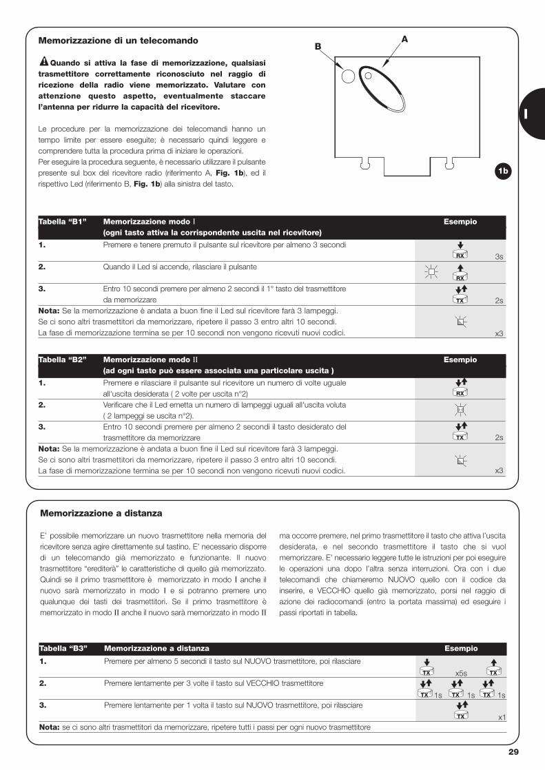
I
29
AB
Memorizzazione di un telecomando
Quando si attiva la fase di memorizzazione, qualsiasitrasmettitore correttamente riconosciuto nel raggio diricezione della radio viene memorizzato. Valutare conattenzione questo aspetto, eventualmente staccarel’antenna per ridurre la capacità del ricevitore.
Le procedure per la memorizzazione dei telecomandi hanno untempo limite per essere eseguite; è necessario quindi leggere ecomprendere tutta la procedura prima di iniziare le operazioni. Per eseguire la procedura seguente, è necessario utilizzare il pulsantepresente sul box del ricevitore radio (riferimento A, Fig. 1b), ed ilrispettivo Led (riferimento B, Fig. 1b) alla sinistra del tasto.
!
3s
2s
x3
2s
x3
1. Premere e tenere premuto il pulsante sul ricevitore per almeno 3 secondi
2. Quando il Led si accende, rilasciare il pulsante
3. Entro 10 secondi premere per almeno 2 secondi il 1° tasto del trasmettitoreda memorizzare
Nota: Se la memorizzazione è andata a buon fine il Led sul ricevitore farà 3 lampeggi.Se ci sono altri trasmettitori da memorizzare, ripetere il passo 3 entro altri 10 secondi.La fase di memorizzazione termina se per 10 secondi non vengono ricevuti nuovi codici.
Tabella “B1” Memorizzazione modo I Esempio(ogni tasto attiva la corrispondente uscita nel ricevitore)
1. Premere e rilasciare il pulsante sul ricevitore un numero di volte ugualeall'uscita desiderata ( 2 volte per uscita n°2)
2. Verificare che il Led emetta un numero di lampeggi uguali all'uscita voluta( 2 lampeggi se uscita n°2).
3. Entro 10 secondi premere per almeno 2 secondi il tasto desiderato del trasmettitore da memorizzare
Nota: Se la memorizzazione è andata a buon fine il Led sul ricevitore farà 3 lampeggi.Se ci sono altri trasmettitori da memorizzare, ripetere il passo 3 entro altri 10 secondi.La fase di memorizzazione termina se per 10 secondi non vengono ricevuti nuovi codici.
Tabella “B2” Memorizzazione modo II Esempio(ad ogni tasto può essere associata una particolare uscita )
RX
RX
TX
TX
RX
1b
x5s
1s 1s 1s
x1
1. Premere per almeno 5 secondi il tasto sul NUOVO trasmettitore, poi rilasciare
2. Premere lentamente per 3 volte il tasto sul VECCHIO trasmettitore
3. Premere lentamente per 1 volta il tasto sul NUOVO trasmettitore, poi rilasciare
Nota: se ci sono altri trasmettitori da memorizzare, ripetere tutti i passi per ogni nuovo trasmettitore
Tabella “B3” Memorizzazione a distanza Esempio
TX
TX TX TX
TX
TX
Memorizzazione a distanza
E’ possibile memorizzare un nuovo trasmettitore nella memoria delricevitore senza agire direttamente sul tastino. E’ necessario disporredi un telecomando già memorizzato e funzionante. Il nuovotrasmettitore “erediterà” le caratteristiche di quello già memorizzato.Quindi se il primo trasmettitore è memorizzato in modo I anche ilnuovo sarà memorizzato in modo I e si potranno premere unoqualunque dei tasti dei trasmettitori. Se il primo trasmettitore èmemorizzato in modo II anche il nuovo sarà memorizzato in modo II
ma occorre premere, nel primo trasmettitore il tasto che attiva l’uscitadesiderata, e nel secondo trasmettitore il tasto che si vuolmemorizzare. E’ necessario leggere tutte le istruzioni per poi eseguirele operazioni una dopo l’altra senza interruzioni. Ora con i duetelecomandi che chiameremo NUOVO quello con il codice dainserire, e VECCHIO quello già memorizzato, porsi nel raggio diazione dei radiocomandi (entro la portata massima) ed eseguire ipassi riportati in tabella.
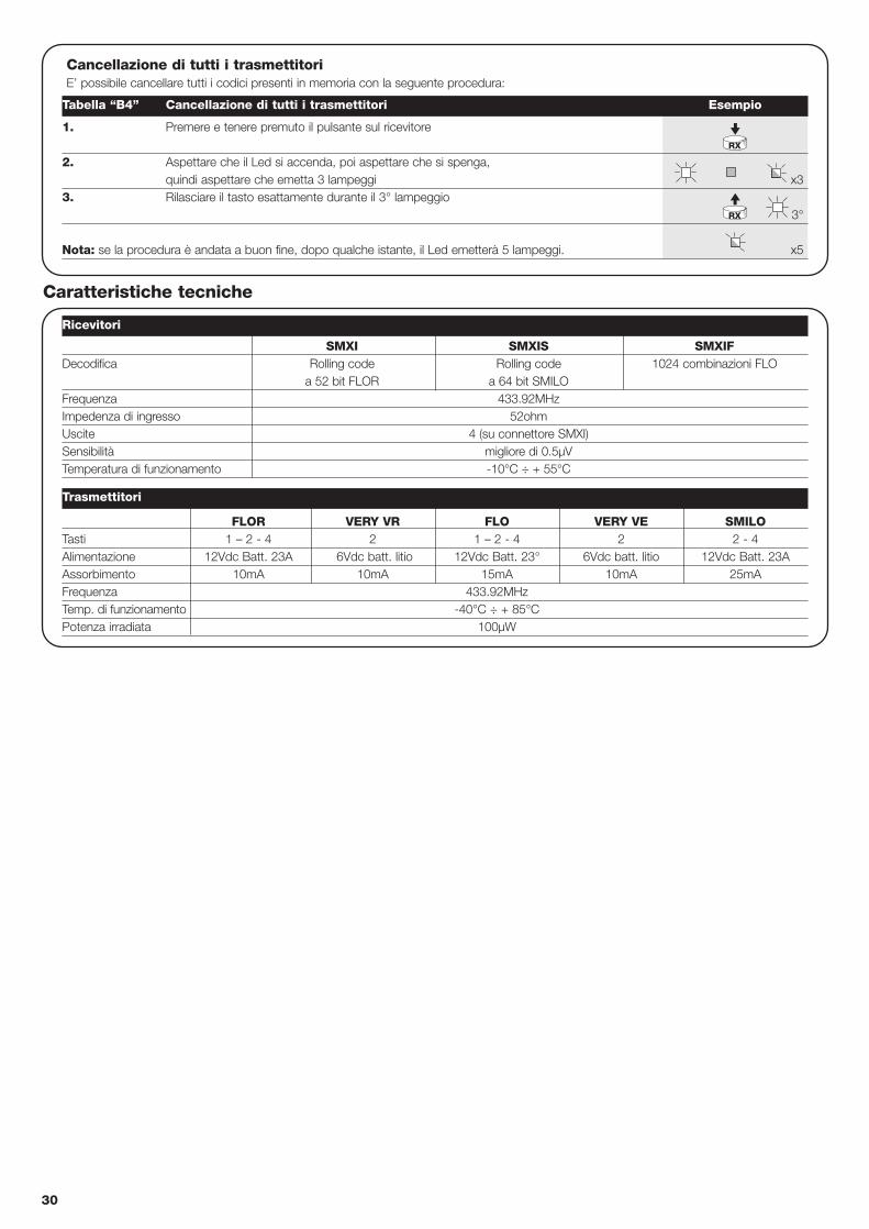
FLOR VERY VR FLO VERY VE SMILOTasti 1 – 2 - 4 2 1 – 2 - 4 2 2 - 4Alimentazione 12Vdc Batt. 23A 6Vdc batt. litio 12Vdc Batt. 23° 6Vdc batt. litio 12Vdc Batt. 23AAssorbimento 10mA 10mA 15mA 10mA 25mAFrequenza 433.92MHzTemp. di funzionamento -40°C ÷ + 85°CPotenza irradiata 100µW
30
Cancellazione di tutti i trasmettitoriE’ possibile cancellare tutti i codici presenti in memoria con la seguente procedura:
x3
3°
x5
1. Premere e tenere premuto il pulsante sul ricevitore
2. Aspettare che il Led si accenda, poi aspettare che si spenga, quindi aspettare che emetta 3 lampeggi
3. Rilasciare il tasto esattamente durante il 3° lampeggio
Nota: se la procedura è andata a buon fine, dopo qualche istante, il Led emetterà 5 lampeggi.
Ricevitori
Trasmettitori
Tabella “B4” Cancellazione di tutti i trasmettitori Esempio
RX
RX
SMXI SMXIS SMXIFDecodifica Rolling code Rolling code 1024 combinazioni FLO
a 52 bit FLOR a 64 bit SMILOFrequenza 433.92MHzImpedenza di ingresso 52ohmUscite 4 (su connettore SMXI)Sensibilità migliore di 0.5µVTemperatura di funzionamento -10°C ÷ + 55°C
Caratteristiche tecniche
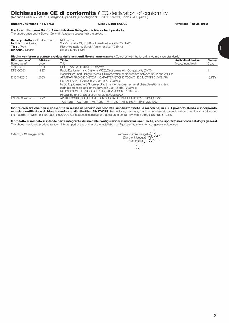
Dichiarazione CE di conformità / EC declaration of conformity(secondo Direttiva 98/37/EC, Allegato II, parte B) (according to 98/37/EC Directive, Enclosure II, part B)
Numero /Number : 151/SMXI Data / Date: 5/2002 Revisione / Revision: 0
Il sottoscritto Lauro Buoro, Amministratore Delegato, dichiara che il prodotto:The undersigned Lauro Buoro, General Manager, declares that the product:
Nome produttore / Producer name: NICE s.p.a.Indirizzo / Address: Via Pezza Alta 13, 31046 Z.I. Rustignè –ODERZO- ITALYTipo / Type: Ricevitore radio 433MHz / Radio receiver 433MHzModello / Model: SMXI, SMXIS, SMXIF
Risulta conforme a quanto previsto dalle seguenti Norme armonizzate / Complies with the following Harmonised standardsRiferimento n° Edizione Titolo Livello di valutazione ClasseReference n° Issue Title Assessment level Class1999/5/CE 1999 DIRETTIVA R&TTE/R&TTE DirectiveETS300683 1997 Radio Equipment and Systems (RES);Electromagnetic Compatibility (EMC) II
standard for Short Range Devices (SRD) operating on frequencies between 9KHz and 25GHzEN300220-3 2000 APPARATI RADIO E SISTEMI - CARATTERISTICHE TECNICHE E METODI DI MISURA I (LPD)
PER APPARATI RADIO TRA 25MHz A 1000MHzRadio Equipment and Sistems- Short Range Devices-Technical characteristics and test methods for radio equipment between 25MHz and 1000MHzREGOLAZIONE ALL’USO DEI DISPOSITIVI A CORTO RAGGIORegolating to the use of short range devices (SRD)
EN60950 2nd ed. 1992 APPARECCHIATURE PERLA TECNOLOGIA DELL’INFORMAZIONE. SICUREZZA. +A1: 1993 + A2: 1993 + A3: 1995 + A4: 1997 + A11: 1997 + EN41003/1993.
Inoltre dichiara che non è consentita la messa in servizio del prodotto suindicato finché la macchina, in cui il prodotto stesso è incorporato,non sia identificata e dichiarata conforme alla direttiva 98/37/CEE/ He declares, moreover, that it is not allowed to use the above mentioned product untilthe machine, in which this product is incorporated, has been identified and declared in conformity with the regulation 98/37/CEE.
Il prodotto suindicato si intende parte integrante di una delle configurazioni di installazione tipiche, come riportato nei nostri cataloghi generaliThe above mentioned product is meant integral part of the of one of the installation configuration as shown on our general catalogues
Oderzo, li 13 Maggio 2002 (Amministratore Delegato)(General Manager)
Lauro Buoro
31
I
32
armoire de commande opérateursrobo, thor
Recommandations :
Ce manuel est destiné exclusivement au personneltechnique qualifié pour l’installation. Aucune informationcontenue dans ce fascicule ne peut être considérée commeintéressante pour l’utilisateur final! L’armoire de commande est destinée à l’actionnement desopérateurs électromécaniques pour l’automatisation deportails ou portes à battant, toute autre utilisation estimpropre et donc interdite par la réglementation en vigueur.Nous conseillons de lire attentivement toutes les instructions, au moinsune fois, avant de procéder à l’installation.
!
Table des matières: page
1 Description du produit 33
2 Installation 332.1 IInstallation typique 332.2 Connexions électriques 342.2.1 Schéma électrique 342.2.2 Description des connexions 342.2.3 Photo-test 352.2.4 Vérification des connexions 36
3 Réglages 36
4 Essai de fonctionnement 37
5 Modes de fonctionnement 38
page
6 Fonctions programmables 386.1 Description des fonctions 39
7 Comment faire pour... 40
8 Accessoires en options 41
9 Maintenance 41
10 Mise au rebut 41
11 Que faire si… 41
12 Caractéristiques techniques 41
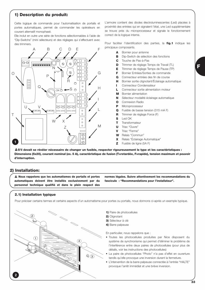
F
33
1) Description du produit:
Cette logique de commande pour l’automatisation de portails etportes automatiques, permet de commander les opérateurs encourant alternatif monophasé.Elle inclut en outre une série de fonctions sélectionnables à l’aide de“Dip-Switchs” (mini sélecteurs) et des réglages qui s’effectuent avecdes trimmers.
L’armoire contient des diodes électroluminescentes (Led) placées àproximité des entrées qui en signalent l’état, une Led supplémentairese trouve près du microprocesseur et signale le fonctionnementcorrect de la logique interne.
Pour faciliter l’identification des parties, la fig.1 indique lesprincipaux composants.
OK
BA C
R
D E F
G
H
I
L
M
P
S
Z
O
T
U V
Q
N
W X
Bornier pour antenneDip-Switch de sélection des fonctionsTouche de Pas-à-PasTrimmer de réglage Temps de Travail (TL)Trimmer de réglage Temps de Pause (TP)Bornier Entrées/Sorties de commandeConnecteur entrées des fin de courseBornier sortie clignotant/Éclairage automatiqueConnecteur CondensateurConnecteur sortie alimentation moteurBornier alimentationSélecteur modalité éclairage automatiqueConnexion RadioMicroprocesseurFusible de basse tension (315 mA F)Trimmer de réglage Force (F)Led OKTransformateurTriac “Ouvre”Triac “Ferme”Relais “Commun”Relais “Éclairage Automatique”Fusible de ligne (5A F)
ABCDEFGHILMNOPQRSTUVWXZ1
2.1) Installation typique
Pour préciser certains termes et certains aspects d’un automatisme pour portes ou portails, nous donnons ci-après un exemple typique.
Nous rappelons que les automatismes de portails et portesautomatiques doivent être installés exclusivement par dupersonnel technique qualifié et dans le plein respect des
normes légales. Suivre attentivement les recommandations dufascicule : “Recommandations pour l’installateur”.
!
2) Installation:
2
4
3
PHOTO
2
1
1) Paire de photocellules2) Clignotant3) Sélecteur à clé4) Barre palpeuse
En particulier, nous rappelons que :• Toutes les photocellules produites par Nice disposent du
système de synchronisme qui permet d’éliminer le problème del’interférence entre deux paires de photocellules (pour plus dedétails, voir les instructions des photocellules)
• La paire de photocellules “Photo” n’a pas d’effet en ouverturetandis qu’elle provoque une inversion durant la fermeture.
• L’intervention de la barre palpeuse connectée à l’entrée “HALTE”provoque l’arrêt immédiat et une brève inversion.
S’il devait se révéler nécessaire de changer un fusible, respecter rigoureusement le type et les caractéristiques :Dimensions (5x20), courant nominal (ex. 5 A), caractéristique de fusion (T=retardée, F=rapide), tension maximum et pouvoird’interruption.
!
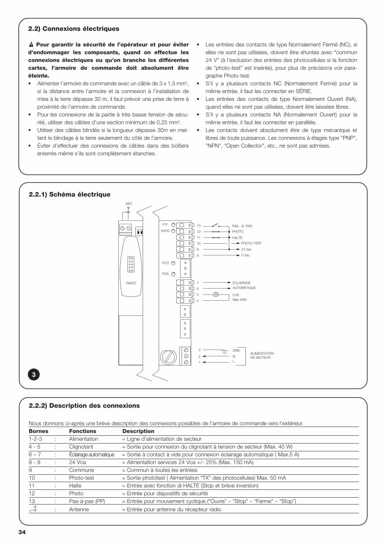
34
2.2.1) Schéma électrique
ALIMENTATIONDE SECTEUR
PAS - À- PAS
PHOTO
FCA
FCC
PHOTO-TEST
24 Vac
0 Vac
8
GND
LUXMax 40W
ANT.
PHOTO
P.P.
HALTE11
10
9
12
13
ÉCLAIRAGEAUTOMATIQUE
4
5
6
L
3
1
2
7
N
RADIO
2.2) Connexions électriques
Pour garantir la sécurité de l’opérateur et pour éviterd’endommager les composants, quand on effectue lesconnexions électriques ou qu’on branche les différentescartes, l’armoire de commande doit absolument êtreéteinte.• Alimenter l’armoire de commande avec un câble de 3 x 1,5 mm2,
si la distance entre l’armoire et la connexion à l’installation demise à la terre dépasse 30 m, il faut prévoir une prise de terre àproximité de l’armoire de commande.
• Pour les connexions de la partie à très basse tension de sécu-rité, utiliser des câbles d’une section minimum de 0,25 mm2.
• Utiliser des câbles blindés si la longueur dépasse 30m en met-tant le blindage à la terre seulement du côté de l’armoire.
• Éviter d’effectuer des connexions de câbles dans des boîtiersenterrés même s’ils sont complètement étanches.
• Les entrées des contacts de type Normalement Fermé (NC), sielles ne sont pas utilisées, doivent être shuntés avec “commun24 V” (à l’exclusion des entrées des photocellules si la fonctionde “photo-test” est insérée), pour plus de précisions voir para-graphe Photo-test.
• S’il y a plusieurs contacts NC (Normalement Fermé) pour lamême entrée, il faut les connecter en SÉRIE.
• Les entrées des contacts de type Normalement Ouvert (NA),quand elles ne sont pas utilisées, doivent être laissées libres.
• S’il y a plusieurs contacts NA (Normalement Ouvert) pour lamême entrée, il faut les connecter en parallèle.
• Les contacts doivent absolument être de type mécanique etlibres de toute puissance. Les connexions à étages type "PNP","NPN", "Open Collector", etc., ne sont pas admises.
!
2.2.2) Description des connexions
Nous donnons ci-après une brève description des connexions possibles de l’armoire de commande vers l’extérieur.Bornes Fonctions Description1-2-3 : Alimentation = Ligne d’alimentation de secteur4 - 5 : Clignotant = Sortie pour connexion du clignotant à tension de secteur (Max. 40 W)6 – 7 : Éclairage automatique = Sortie à contact à vide pour connexion éclairage automatique ( Max.5 A)8 - 9 : 24 Vca = Alimentation services 24 Vca +/- 25% (Max. 150 mA) 9 : Commune = Commun à toutes les entrées10 : Photo-test = Sortie phototest ( Alimentation “TX” des photocellules) Max. 50 mA11 : Halte = Entrée avec fonction di HALTE (Stop et brève inversion)12 : Photo = Entrée pour dispositifs de sécurité13 : Pas-à-pas (PP) = Entrée pour mouvement cyclique (“Ouvre” – “Stop” – “Ferme” – “Stop”)
: Antenne = Entrée pour antenne du récepteur radio
3
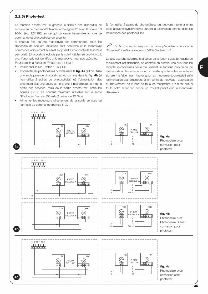
F
35
2.2.3) Photo-test
La fonction “Photo-test” augmente la fiabilité des dispositifs desécurité en permettant d’atteindre la “catégorie 2” selon la norme EN954-1 (éd. 12/1998) en ce qui concerne l’ensemble armoire decommande et photocellules de sécurité.À chaque fois qu’une manœuvre est commandée, tous lesdispositifs de sécurité impliqués sont contrôlés et la manœuvrecommence uniquement si le test est positif. Si par contre le test n’estpas positif (photocellule éblouie par le soleil, câbles en court-circuit,etc.) l’anomalie est identifiée et la manœuvre n’est pas exécutée.Pour obtenir la Fonction “Photo-test”, il faut :• Positionner le Dip-Switch 10 sur ON • Connecter les photocellules comme dans la fig. 4a (si l’on utilise
une seule paire de photocellules) ou comme dans la fig. 4b (sil’on utilise 2 paires de photocellules) où l’alimentation desémetteurs des photocellules ne provient pas directement de lasortie des services, mais de la sortie “Photo-test” entre lesbornes (8-10). Le courant maximum utilisable sur la sortie“Photo-test” est de 500 mA (2 paires de TX Nice)
• Alimenter les récepteurs directement de la sortie services del’armoire de commande (bornes 8-9).
Si l’on utilise 2 paires de photocellules qui peuvent interférer entreelles, activer le synchronisme suivant la description donnée dans lesinstructions des photocellules.
Si dans un second temps on ne désire plus utiliser la fonction de
“Photo-test”, il suffira de mettre sur OFF le Dip-Switch 10.
Le test des photocellules s’effectue de la façon suivante: quand unmouvement est demandé, on contrôle en premier lieu que tous lesrécepteurs concernés par le mouvement l’autorisent, puis on coupel’alimentation des émetteurs et on vérifie que tous les récepteurssignalent le fait en niant l’autorisation au mouvement; on rétablit enfinl'alimentation des émetteurs et on vérifie de nouveau l’autorisationau mouvement de la part de tous les récepteurs. Ce n’est que sitoute cette séquence donne un résultat positif que la manœuvredémarrera.
3 4 5
RX
1 2
9
98
TX
21
98 12
RX
4 5
PHOTOCELLULE
321
TX
PHOTOCELLULE
21
1311 1298 10
RxA
RxB
5421 3
1298
PHOTOCELLULE B
5
RXBTXB
21
810
RXB
4 5321
TXB
PHOTOCELLULE B21
5421 3
98
PHOTOCELLULE A
59
RXATXA
21
810
4 5
RXA
1311 12
2 31
TXA
PHOTOCELLULE A
1 2
98 10
12 13111098
RX
3 4 51 2
9
912
8
PHOTOCELLULE1 2
108
RX
3 4 51 2
TX
1 2
PHOTOCELLULE
TX
4a
4b
4c
fig. 4aPhotocellule avecconnexion pour phototest
fig. 4bPhotocellule A etPhotocellule B avecconnexion pour phototest
fig. 4cPhotocellule avecconnexion sans phototest
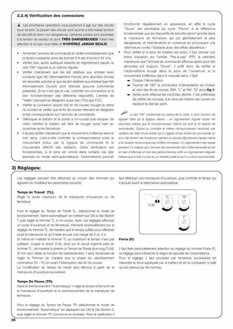
36
2.2.4) Vérification des connexions
Les prochaines opérations vous porteront à agir sur des circuitssous tension, la plupart des circuits sont soumis à très basse tensionde sécurité et donc non dangereuse, certaines parties sont soumisesà la tension de secteur et donc TRÈS DANGEREUSES! Faites trèsattention à ce que vous faites et N’OPÉREZ JAMAIS SEULS!
• Alimenter l’armoire de commande et vérifier immédiatement quela tension présente entre les bornes 8-9 est d’environ 24 Vca.
• Vérifier que, après quelques instants de clignotement rapide, laLed “OK” clignote à un rythme régulier.
• Vérifier maintenant que les led relatives aux entrées aveccontacts type NC (Normalement Fermé) sont allumées (toutesles sécurités actives) et que les led relatives aux entrées type NA(Normalement Ouvert) sont éteintes (aucune commandeprésente). Si ce n’est pas le cas, contrôler les connexions et lebon fonctionnement des différents dispositifs. L’entrée de“Halte” intervient en éteignant aussi bien FCA que FCC.
• Vérifier la connexion exacte des fin de course; bouger la camedu contact et vérifier que le fin de course intervient en éteignantla led correspondante sur l’armoire de commande.
• Débloquer le battant et le porter à mi-course puis bloquer, decette manière le battant est libre de bouger aussi bien enouverture qu’en fermeture.
• Il faudra vérifier maintenant que le mouvement s’effectue dans lebon sens, c’est-à-dire contrôler la correspondance entre lemouvement prévu par la logique de commande et lemouvement effectif des battants. Cette vérification estfondamentale, si le sens est erroné dans certains cas (parexemple en mode semi-automatique), l’automatisme pourrait
fonctionner régulièrement en apparence, en effet le cycle“Ouvre” est semblable au cycle “Ferme” à la différencefondamentale que les dispositifs de sécurité seront ignorés dansla manœuvre de fermeture, qui est généralement la plusdangereuse, et interviendront en ouverture en provoquant unerefermeture contre l’obstacle avec des effets désastreux !
• Pour vérifier si le sens de rotation est exact, il faut donner unebrève impulsion sur l’entrée “Pas-à-pas” (PP); la premièremanœuvre que l’armoire de commande effectue après avoir étéalimentée est toujours “Ouvre”, il suffit donc de vérifier sil’automatisme bouge dans le sens de l’ouverture; si lemouvement s’effectue dans le mauvais sens, il faut:
� Couper l’alimentation� Tourner de 180° le connecteur d’alimentation du moteur
et celui des fin de course. (Réf. “L” et Réf. “G” de la fig.1)� Après avoir effectué les contrôles décrits, il est préférable
de vérifier de nouveau si le sens de rotation est correct enrépétant le dernier point.
La led “OK” positionnée au centre de la carte, a pour fonction de
signaler l’état de la logique interne : un clignotement régulier toutes les
secondes indique que le microprocesseur interne est actif et en attente de
commandes. Quand au contraire le même microprocesseur reconnaît une
variation de l’état d’une entrée (qu’il s’agisse d’une entrée de commande ou
d’un Dip-Switch des fonctions) il génère un double clignotement rapide même
si la variation ne provoque pas d’effets immédiats. Un clignotement très rapide
pendant 3 s indique que l’armoire de commande vient d’être alimentée et est
en train d’effectuer un test des parties internes, enfin un clignotement irrégulier
indique que le test n’a pas eu un résultat positif et qu’il y a donc une anomalie.
!
Les réglages peuvent être effectués au moyen des trimmers quiagissent en modifiant les paramètres suivants:
Temps de Travail (TL): Règle la durée maximum de la manœuvre d’ouverture ou defermeture.
Pour le réglage du Temps de Travail TL, sélectionner le mode defonctionnement “Semi-automatique” en mettant sur ON le Dip-Switch1 puis régler le trimmer TL à mi-course. Avec ces réglages effectuerun cycle d’ouverture et de fermeture, intervenir éventuellement sur leréglage du trimmer TL de manière que le temps suffise pour effectuertoute la manœuvre et qu’il reste encore une marge de 2 ou 3 s. Si même en mettant le trimmer TL au maximum le temps n’est passuffisant, couper le shunt TLM, situé sur le circuit imprimé près dutrimmer TL, de manière à obtenir un Temps de Travail plus long (TLM).Si l’on veut utiliser la fonction de ralentissement, il sera nécessaire derégler le Trimmer de manière que la phase de ralentissementcommence 50 - 70 cm avant l’interruption des fin de course.La modification du temps de travail sera efficace à partir de lamanœuvre d’ouverture successive.
Temps De Pause (TP):Dans le fonctionnement “Automatique” il règle le temps entre la fin dela manœuvre d’ouverture et le commencement de la manœuvre defermeture.
Pour le réglage du Temps de Pause TP, sélectionner le mode defonctionnement “Automatique” en déplaçant sur ON le Dip-Switch 2,puis régler le trimmer TP comme on le souhaite. Pour la vérification il
faut effectuer une manœuvre d’ouverture, puis contrôler le temps quis’écoule avant la refermeture automatique.
Force (F):
Il faut faire particulièrement attention au réglage du trimmer Force (F),ce réglage peut influencer le degré de sécurité de l’automatisme.Pour le réglage, il faut procéder par tentatives successives enmesurant la force appliquée par le battant et en la comparant à cellequi est prévue par les normes.
3) Réglages:
F
TL TP
TLM
F
37
Après avoir terminé les contrôles et les réglages, il est possible de passer à l’essai de fonctionnement de l’installation.
L’essai de fonctionnement de l’automatisme doit être effectué par du personnel qualifié et expérimenté qui devra secharger d’établir les essais prévus en fonction du risque présent.
L’essai de fonctionnement est la partie la plus importante de toute la phase de réalisation de l’automatisme. Chaque composant, commel’opérateur, l’arrêt d’urgence, les photocellules, etc., peut nécessiter une phase d’essai spécifique ; nous conseillons de suivre les procéduresindiquées dans les manuels d’instructions correspondants.
Pour l’essai de l’armoire de commande, exécuter la procédure qui suit:
1. Sélections fonctions: • Positionner sur ON le Dip-Switch 1 (Fonctionnement “Semi-automatique”)• Positionner sur OFF tous les autres Dip-Switchs
2. Presser la touche de commande “Pas-à-pas” et vérifier que:• Une manœuvre d’ouverture commence• Le clignotant s’active• Le mouvement s’arrête quand le fin de course en ouverture FCA est atteint.
3. Presser de nouveau la touche de commande“Pas-à-pas” et vérifier que:• Une manœuvre de fermeture commence• Le clignotant s’active• Le mouvement s’arrête quand le fin de course en fermeture FCC est atteint.
4. Faire partir une manœuvre d’ouverture et vérifier que durant la manœuvre l’intervention d’un dispositif:• Connecté à l’entrée Halte, provoque l’arrêt immédiat du mouvement et une brève inversion• Connecté à l’entrée “Photo”, n’a aucun effet
5. Faire partir une manœuvre de fermeture et vérifier que durant la manœuvre l’intervention d’un dispositif:• Connecté à l’entrée “Halte”, provoque l’arrêt immédiat du mouvement et une brève inversion• Connecté à l’entrée “Photo”, provoque l’arrêt et l’inversion de la manœuvre
6. Presser la touche de “Pas-à-Pas” et vérifier que chaque activation de l’entrée provoque un pas dans la séquence:• “Ouvre” – “Stop” – “Ferme” – “Stop”
7. Si on utilise la fonction “Photo-test” vérifier l’efficacité du test• Interrompre la photocellule “Photo”, puis faire partir une manœuvre et vérifier que celle-ci n’est pas exécutée• Court-circuiter le contact de la photocellule “Photo”, puis faire partir une manœuvre et vérifier que celle-ci n’est pas exécutée.
8. Effectuer les essais pour la détection des “Forces d’Impact” comme le prévoit la norme EN 12445.
Si à la fin de l’essai d’autres fonctions programmables qui peuvent réduire la sécurité de l’installation sont activées, il faut effectuer uncontrôle spécifique de ces fonctions.
!
4) Essai de fonctionnement
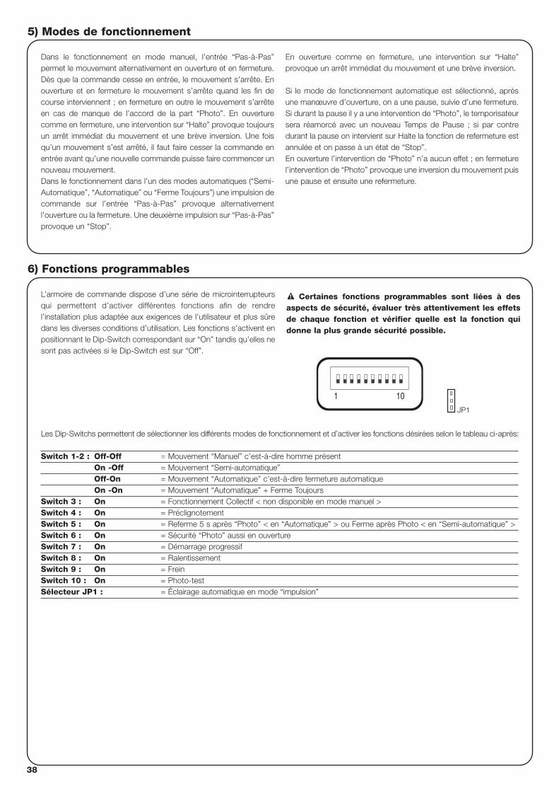
38
5) Modes de fonctionnement
Dans le fonctionnement en mode manuel, l’entrée “Pas-à-Pas”permet le mouvement alternativement en ouverture et en fermeture.Dès que la commande cesse en entrée, le mouvement s’arrête. Enouverture et en fermeture le mouvement s’arrête quand les fin decourse interviennent ; en fermeture en outre le mouvement s’arrêteen cas de manque de l’accord de la part “Photo”. En ouverturecomme en fermeture, une intervention sur “Halte” provoque toujoursun arrêt immédiat du mouvement et une brève inversion. Une foisqu’un mouvement s’est arrêté, il faut faire cesser la commande enentrée avant qu’une nouvelle commande puisse faire commencer unnouveau mouvement.Dans le fonctionnement dans l’un des modes automatiques (“Semi-Automatique”, “Automatique” ou “Ferme Toujours”) une impulsion decommande sur l’entrée “Pas-à-Pas” provoque alternativementl’ouverture ou la fermeture. Une deuxième impulsion sur “Pas-à-Pas”provoque un “Stop”.
En ouverture comme en fermeture, une intervention sur “Halte”provoque un arrêt immédiat du mouvement et une brève inversion.
Si le mode de fonctionnement automatique est sélectionné, aprèsune manœuvre d’ouverture, on a une pause, suivie d’une fermeture.Si durant la pause il y a une intervention de “Photo”, le temporisateursera réamorcé avec un nouveau Temps de Pause ; si par contredurant la pause on intervient sur Halte la fonction de refermeture estannulée et on passe à un état de “Stop”.En ouverture l’intervention de “Photo” n’a aucun effet ; en fermeturel’intervention de “Photo” provoque une inversion du mouvement puisune pause et ensuite une refermeture.
L’armoire de commande dispose d’une série de microinterrupteursqui permettent d’activer différentes fonctions afin de rendrel’installation plus adaptée aux exigences de l’utilisateur et plus sûredans les diverses conditions d’utilisation. Les fonctions s’activent enpositionnant le Dip-Switch correspondant sur “On” tandis qu’elles nesont pas activées si le Dip-Switch est sur “Off”.
Certaines fonctions programmables sont liées à desaspects de sécurité, évaluer très attentivement les effetsde chaque fonction et vérifier quelle est la fonction quidonne la plus grande sécurité possible.
!
Les Dip-Switchs permettent de sélectionner les différents modes de fonctionnement et d’activer les fonctions désirées selon le tableau ci-après:
Switch 1-2 : Off-Off = Mouvement “Manuel” c’est-à-dire homme présentOn -Off = Mouvement “Semi-automatique”Off-On = Mouvement “Automatique” c’est-à-dire fermeture automatiqueOn -On = Mouvement “Automatique” + Ferme Toujours
Switch 3 : On = Fonctionnement Collectif < non disponible en mode manuel >Switch 4 : On = PréclignotementSwitch 5 : On = Referme 5 s après “Photo” < en “Automatique” > ou Ferme après Photo < en “Semi-automatique” >Switch 6 : On = Sécurité “Photo” aussi en ouvertureSwitch 7 : On = Démarrage progressifSwitch 8 : On = RalentissementSwitch 9 : On = FreinSwitch 10 : On = Photo-testSélecteur JP1 : = Éclairage automatique en mode “impulsion”
6) Fonctions programmables
101
JP1
F
39
6.1) Description des fonctions
Nous reportons maintenant une brève description des fonctions qui peuvent s’activer en portant sur “On” le Dip-Switch correspondant
Switch 1-2: Off-Off = Mouvement “Manuel” (homme présent)On-Off = Mouvement “Semi-automatique”Off-On = Mouvement “Automatique” (fermeture automatique)On-On = Mouvement “Automatique” + “Ferme Toujours”
Dans le fonctionnement “Manuel” le mouvement est exécuté seulement jusqu’à la présence de la commande (touche pressée).En “Semi-automatique” il suffit d’une impulsion de commande et tout le mouvement est exécuté jusqu’à l’expiration du Temps de Travail ouquand le fin de course est atteint. Dans le fonctionnement en mode “Automatique” après une ouverture, il y a une pause et donc la fermeturea lieu automatiquement.La fonction “Ferme Toujours” intervient après un manque d’alimentation ; si la logique de commande détecte le portail ouvert, une manœuvrede fermeture démarre automatiquement, précédée de 5 s de préclignotement.
Switch 3: On = Fonctionnement Collectif (non disponible en mode manuel) Dans le fonctionnement collectif, une fois qu’un mouvement en ouverture a démarré, la manœuvre ne peut pas être interrompue par d’autresimpulsions de commande sur Pas-à-Pas jusqu’à la fin du mouvement en ouverture.Dans le mouvement en fermeture une nouvelle impulsion de commande provoque l’arrêt et l’inversion du mouvement en ouverture.
Switch 4: On = PréclignotementÀ l’impulsion de commande on a d’abord l’activation du clignotant puis, au bout de 5 s (2 en manuel), le mouvement commence.
Switch 5: On = Referme 5 s après “Photo” < en “automatique” > ou “Ferme” après “Photo” < en “Semi-automatique”> Cette fonction, si on est en mode Automatique, permet de maintenir le portail ouvert seulement le temps nécessaire au transit, en effet, à lafin de l’intervention de “Photo” la manœuvre s’arrête. Au bout de 5 s, une manœuvre de fermeture commencera automatiquement. Si onest en mode Semi-automatique, une intervention de “Photo” dans la manœuvre de fermeture active la fermeture automatique avec le Tempsde Pause réglé.
Switch 6: On = Sécurité “Photo” également en ouvertureNormalement la sécurité “Photo” est active seulement dans la manœuvre de fermeture, si le Dip-Switch 6 est positionné sur “ON”,l'intervention du dispositif de sécurité provoque une interruption du mouvement également en ouverture.Si on est en mode Semi-automatique ou Automatique on aura la reprise du mouvement en ouverture jusqu’après la libération de laphotocellule.
Switch 7: On = Démarrage progressifExécute le début du mouvement de manière progressive en évitant les secousses de l’automatisme.
Switch 8: On = Ralentissement Le ralentissement consiste en une réduction de la vitesse à 30% de la vitesse nominale de manière à diminuer la force d’impact dans leszones d’ouverture et de fermeture du portail.
Une fois que la fonction de ralentissement est activée, il faut agir sur le Trimmer Temps de Travail (TL) dans la mesure où le début duralentissement est lié au temps de travail programmé. Régler par conséquent le temps de travail de manière que le ralentissementcommence environ 50-70 cm avant l’intervention des fin de course.
La fonction de ralentissement en plus de diminuer la vitesse de l’automatisme réduit de 70% le couple du moteur.
Dans les automatismes nécessitant un couple élevé, cette réduction pourrait provoquer l’arrêt immédiat du moteur.
Switch 9: On = FreinÀ la fin du mouvement, l’automatisme prévoit dans ce cas une procédure de freinage du moteur, d’abord légère puis plus forte de manièreà arrêter le portail rapidement mais sans secousses.
Switch 10: On = PhototestCette fonction permet d’effectuer à chaque début de manœuvre un contrôle du bon fonctionnement des photocellules. Voir chapitre “Photo-test”.
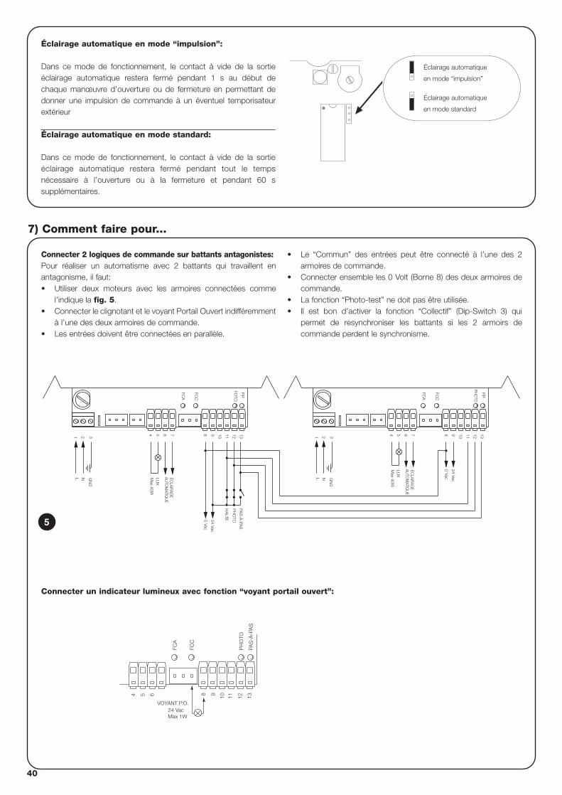
40
Connecter 2 logiques de commande sur battants antagonistes:Pour réaliser un automatisme avec 2 battants qui travaillent enantagonisme, il faut:• Utiliser deux moteurs avec les armoires connectées comme
l’indique la fig. 5.• Connecter le clignotant et le voyant Portail Ouvert indifféremment
à l’une des deux armoires de commande.• Les entrées doivent être connectées en parallèle.
• Le “Commun” des entrées peut être connecté à l’une des 2armoires de commande.
• Connecter ensemble les 0 Volt (Borne 8) des deux armoires decommande.
• La fonction “Photo-test” ne doit pas être utilisée.• Il est bon d’activer la fonction “Collectif” (Dip-Switch 3) qui
permet de resynchroniser les battants si les 2 armoirs decommande perdent le synchronisme.
7) Comment faire pour...
N
7
21 3
L
654 13129 10 11H
ALTE
P.P.
FOTO
Max 40W
LUX
GN
D
8
0 Vac
24 Vac
FCC
FCA
PH
OTO
PAS
-À-PA
S
11
0 Vac
24 Vac
AUTO
MATIQ
UE
Max 40W
GN
D3
NL
1 2
LUX
ÉCLAIR
AGE
54 76 8 9 10
FCA
FCC
12 13
PHO
TO
P.P.
AUTO
MATIQ
UE
ÉCLAIR
AGE
5
Éclairage automatique en mode “impulsion”:
Dans ce mode de fonctionnement, le contact à vide de la sortieéclairage automatique restera fermé pendant 1 s au début dechaque manœuvre d’ouverture ou de fermeture en permettant dedonner une impulsion de commande à un éventuel temporisateurextérieur
Éclairage automatique en mode standard:
Dans ce mode de fonctionnement, le contact à vide de la sortieéclairage automatique restera fermé pendant tout le tempsnécessaire à l’ouverture ou à la fermeture et pendant 60 ssupplémentaires.
Éclairage automatique
en mode “impulsion”
Éclairage automatique
en mode standard
FCC
FCA
PAS
-À-P
AS
54 6 1198 10 12 13
24 VacVOYANT P.O.
Max 1W
PH
OTO
Connecter un indicateur lumineux avec fonction “voyant portail ouvert”:
F
41
Carte RADIOL’armoire comprend un connecteur pour brancher une carte radio,SMXI, qui permet d’agir sur l’entrée de “Pas-à-Pas” et “Halte” etcommander de cette manière l’armoire à distance avec un émetteur.
sortie 1 P.P.sortie 2 HALTEsortie 3 non utiliséesortie 4 non utilisée
8) Accessoires en option
L’armoire de commande, en tant que partie électronique, n’a besoind’aucune maintenance particulière. Vérifier dans tous les caspériodiquement (au moins tous les 6 mois), le bon fonctionnement etle réglage du dispositif de réglage de la Force du moteur, agiréventuellement sur le trimmer de réglage.
Refaire en entier la phase d’essai de fonctionnement pour contrôlerle bon fonctionnement des fin de course, des dispositifs de sécurité(photocellules, barres palpeuses, etc.) et le fonctionnement correctdu clignotant.
9) Maintenance
Ce produit est constitué de différents types de matériaux dontcertains peuvent être recyclés.Informez-vous sur les méthodes de recyclage ou de mise au rebuten suivant les normes en vigueur sur le plan local.
Certains composants électriques peuvent contenir dessubstances polluantes, ne les abandonnez pas dans lanature.
!
10) Mise au rebut
Ce chapitre est un guide visant à aider l’installateur à résoudrequelques uns des problèmes les plus courants qui peuvent seprésenter durant l’installation.
Aucune led n’est allumée: • Vérifier si l’armoire de commande est alimentée (vérifier que la
tension de secteur arrive aux bornes 1-2 et qu’il y a une tensiond’environ 24 Vca aux bornes 8-9)
• Vérifier si les 2 fusibles d’alimentation sont intacts et si aucuneLed n’est allumée même dans ce cas, on est probablement enprésence d’une panne grave et l’armoire de commande devraêtre remplacée.
La led OK clignote régulièrement mais les LED ENTRÉESne reflètent pas l’état des entrées respectives• Vérifier attentivement les connexions sur les bornes des entrées
8÷13.La manœuvre ne démarre pas • Vérifier que les Led des sécurités “Halte” (FCA + FCC) et “Photo”
sont allumées et que la Led de la commande qui est activée(“Pas-à-Pas”) s’allume pendant la durée de la commande.
Durant le mouvement le portail effectue une inversion Les causes qui provoquent une inversion sont: • Une intervention des photocellules (“Foto” durant la fermeture);
dans ce cas contrôler les connexions des photocellules et vérifieréventuellement les Led de signalisation des entrées.
11) Que faire si….
Alimentation de secteur : 230 Vac 50/60 HzVersions /V1 : 120 Vac 50/60 Hz
Courant Max. services 24 V : 200 mA (la tension peut varier de ± 25%)Sortie clignotant : Pour clignotants à la tension de secteur, puissance maximum 40 WSortie éclairage automatique : Contact à vide max. 5 ATempérature de fonctionnement : -20 ÷ 70°CTemps de Travail : Réglable de 2.5 à > 40 s, ou de < 40 à > 80 s avec TLMTemps de Pause : Réglable de 5 à > 80 s
12) Caractéristiques techniques
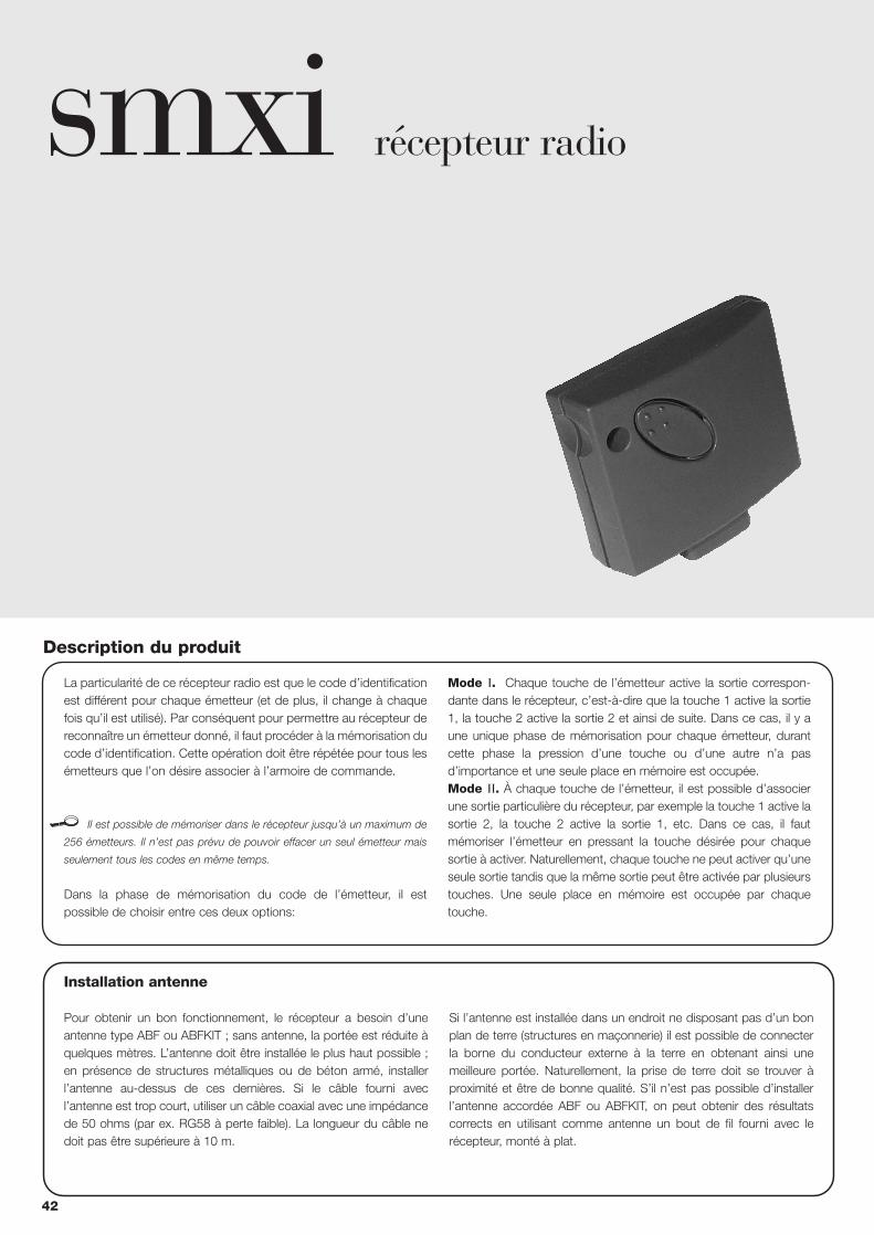
smxi récepteur radio
Description du produit
La particularité de ce récepteur radio est que le code d’identificationest différent pour chaque émetteur (et de plus, il change à chaquefois qu’il est utilisé). Par conséquent pour permettre au récepteur dereconnaître un émetteur donné, il faut procéder à la mémorisation ducode d’identification. Cette opération doit être répétée pour tous lesémetteurs que l’on désire associer à l’armoire de commande.
Il est possible de mémoriser dans le récepteur jusqu’à un maximum de
256 émetteurs. Il n’est pas prévu de pouvoir effacer un seul émetteur mais
seulement tous les codes en même temps.
Dans la phase de mémorisation du code de l’émetteur, il estpossible de choisir entre ces deux options:
Mode I. Chaque touche de l’émetteur active la sortie correspon-dante dans le récepteur, c’est-à-dire que la touche 1 active la sortie1, la touche 2 active la sortie 2 et ainsi de suite. Dans ce cas, il y aune unique phase de mémorisation pour chaque émetteur, durantcette phase la pression d’une touche ou d’une autre n’a pasd’importance et une seule place en mémoire est occupée.Mode II. À chaque touche de l’émetteur, il est possible d’associerune sortie particulière du récepteur, par exemple la touche 1 active lasortie 2, la touche 2 active la sortie 1, etc. Dans ce cas, il fautmémoriser l’émetteur en pressant la touche désirée pour chaquesortie à activer. Naturellement, chaque touche ne peut activer qu’uneseule sortie tandis que la même sortie peut être activée par plusieurstouches. Une seule place en mémoire est occupée par chaquetouche.
Installation antenne
Pour obtenir un bon fonctionnement, le récepteur a besoin d’uneantenne type ABF ou ABFKIT ; sans antenne, la portée est réduite àquelques mètres. L’antenne doit être installée le plus haut possible ;en présence de structures métalliques ou de béton armé, installerl’antenne au-dessus de ces dernières. Si le câble fourni avecl’antenne est trop court, utiliser un câble coaxial avec une impédancede 50 ohms (par ex. RG58 à perte faible). La longueur du câble nedoit pas être supérieure à 10 m.
Si l’antenne est installée dans un endroit ne disposant pas d’un bonplan de terre (structures en maçonnerie) il est possible de connecterla borne du conducteur externe à la terre en obtenant ainsi unemeilleure portée. Naturellement, la prise de terre doit se trouver àproximité et être de bonne qualité. S’il n’est pas possible d’installerl’antenne accordée ABF ou ABFKIT, on peut obtenir des résultatscorrects en utilisant comme antenne un bout de fil fourni avec lerécepteur, monté à plat.
42
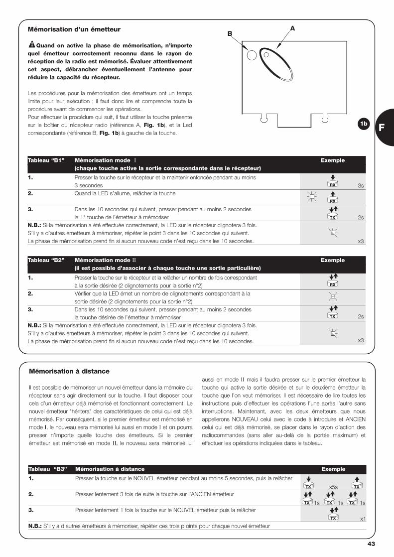
AB
Mémorisation d’un émetteur
Quand on active la phase de mémorisation, n’importequel émetteur correctement reconnu dans le rayon deréception de la radio est mémorisé. Évaluer attentivementcet aspect, débrancher éventuellement l’antenne pourréduire la capacité du récepteur.
Les procédures pour la mémorisation des émetteurs ont un tempslimite pour leur exécution ; il faut donc lire et comprendre toute laprocédure avant de commencer les opérations.Pour effectuer la procédure qui suit, il faut utiliser la touche présentesur le boîtier du récepteur radio (référence A, Fig. 1b), et la Ledcorrespondante (référence B, Fig. 1b) à gauche de la touche.
!
3s
2s
x3
2s
x3
1. Presser la touche sur le récepteur et la maintenir enfoncée pendant au moins 3 secondes
2. Quand la LED s’allume, relâcher la touche
3. Dans les 10 secondes qui suivent, presser pendant au moins 2 secondes la 1° touche de l’émetteur à mémoriser
N.B.: Si la mémorisation a été effectuée correctement, la LED sur le récepteur clignotera 3 fois. S’il y a d’autres émetteurs à mémoriser, répéter le point 3 dans les 10 secondes qui suivent.La phase de mémorisation prend fin si aucun nouveau code n’est reçu dans les 10 secondes.
Tableau “B1” Mémorisation mode I Exemple(chaque touche active la sortie correspondante dans le récepteur)
1. Presser la touche sur le récepteur et la relâcher un nombre de fois correspondant à la sortie désirée (2 clignotements pour la sortie n°2)
2. Vérifier que la LED émet un nombre de clignotements correspondant à la sortie désirée (2 clignotements pour la sortie n°2)
3. Dans les 10 secondes qui suivent, presser pendant au moins 2 secondesla touche désirée de l’émetteur à mémoriser
N.B.: Si la mémorisation a été effectuée correctement, la LED sur le récepteur clignotera 3 fois.S’il y a d’autres émetteurs à mémoriser, répéter le point 3 dans les 10 secondes qui suivent. La phase de mémorisation prend fin si aucun nouveau code n’est reçu dans les 10 secondes.
Tableau “B2” Mémorisation mode II Exemple(il est possible d’associer à chaque touche une sortie particulière)
RX
RX
TX
TX
RX
1b
x5s
1s 1s 1s
x1
1. Presser la touche sur le NOUVEL émetteur pendant au moins 5 secondes, puis la relâcher
2. Presser lentement 3 fois de suite la touche sur l’ANCIEN émetteur
3. Presser lentement 1 fois la touche sur le NOUVEL émetteur puis la relâcher
N.B.: S’il y a d’autres émetteurs à mémoriser, répéter ces trois p oints pour chaque nouvel émetteur
Tableau “B3” Mémorisation à distance Exemple
TX
TX TX TX
TX
TX
Mémorisation à distance
Il est possible de mémoriser un nouvel émetteur dans la mémoire durécepteur sans agir directement sur la touche. Il faut disposer pourcela d’un émetteur déjà mémorisé et fonctionnant correctement. Lenouvel émetteur "héritera" des caractéristiques de celui qui est déjàmémorisé. Par conséquent, si le premier émetteur est mémorisé enmode I, le nouveau sera mémorisé lui aussi en mode I et on pourrapresser n’importe quelle touche des émetteurs. Si le premierémetteur est mémorisé en mode II, le nouveau sera mémorisé lui
aussi en mode II mais il faudra presser sur le premier émetteur latouche qui active la sortie désirée et sur le deuxième émetteur latouche que l’on veut mémoriser. Il est nécessaire de lire toutes lesinstructions puis d’effectuer les opérations l’une après l’autre sansinterruptions. Maintenant, avec les deux émetteurs que nousappellerons NOUVEAU celui avec le code à introduire et ANCIENcelui qui est déjà mémorisé, se placer dans le rayon d’action desradiocommandes (sans aller au-delà de la portée maximum) eteffectuer les opérations indiquées dans le tableau.
F
43
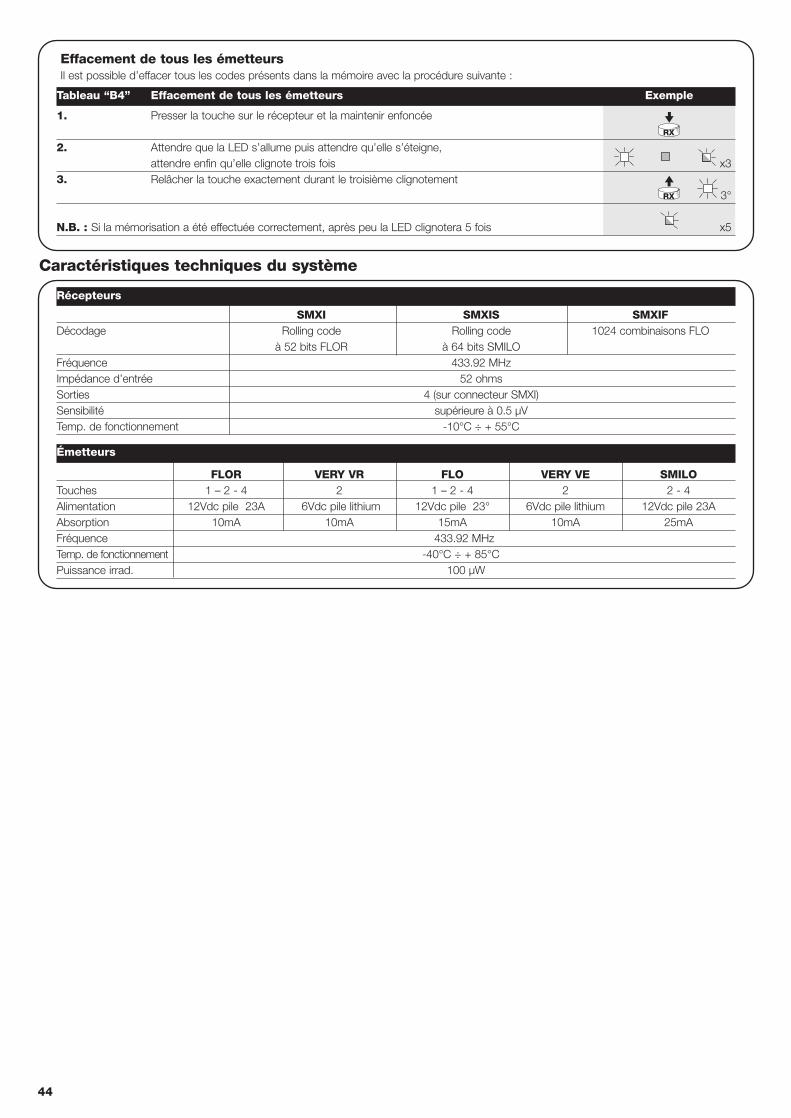
44
FLOR VERY VR FLO VERY VE SMILOTouches 1 – 2 - 4 2 1 – 2 - 4 2 2 - 4Alimentation 12Vdc pile 23A 6Vdc pile lithium 12Vdc pile 23° 6Vdc pile lithium 12Vdc pile 23AAbsorption 10mA 10mA 15mA 10mA 25mAFréquence 433.92 MHzTemp. de fonctionnement -40°C ÷ + 85°CPuissance irrad. 100 µW
Effacement de tous les émetteursIl est possible d’effacer tous les codes présents dans la mémoire avec la procédure suivante :
x3
3°
x5
1. Presser la touche sur le récepteur et la maintenir enfoncée
2. Attendre que la LED s’allume puis attendre qu’elle s’éteigne,attendre enfin qu’elle clignote trois fois
3. Relâcher la touche exactement durant le troisième clignotement
N.B. : Si la mémorisation a été effectuée correctement, après peu la LED clignotera 5 fois
Récepteurs
Émetteurs
Tableau “B4” Effacement de tous les émetteurs Exemple
RX
RX
SMXI SMXIS SMXIFDécodage Rolling code Rolling code 1024 combinaisons FLO
à 52 bits FLOR à 64 bits SMILOFréquence 433.92 MHzImpédance d’entrée 52 ohmsSorties 4 (sur connecteur SMXI)Sensibilité supérieure à 0.5 µVTemp. de fonctionnement -10°C ÷ + 55°C
Caractéristiques techniques du système
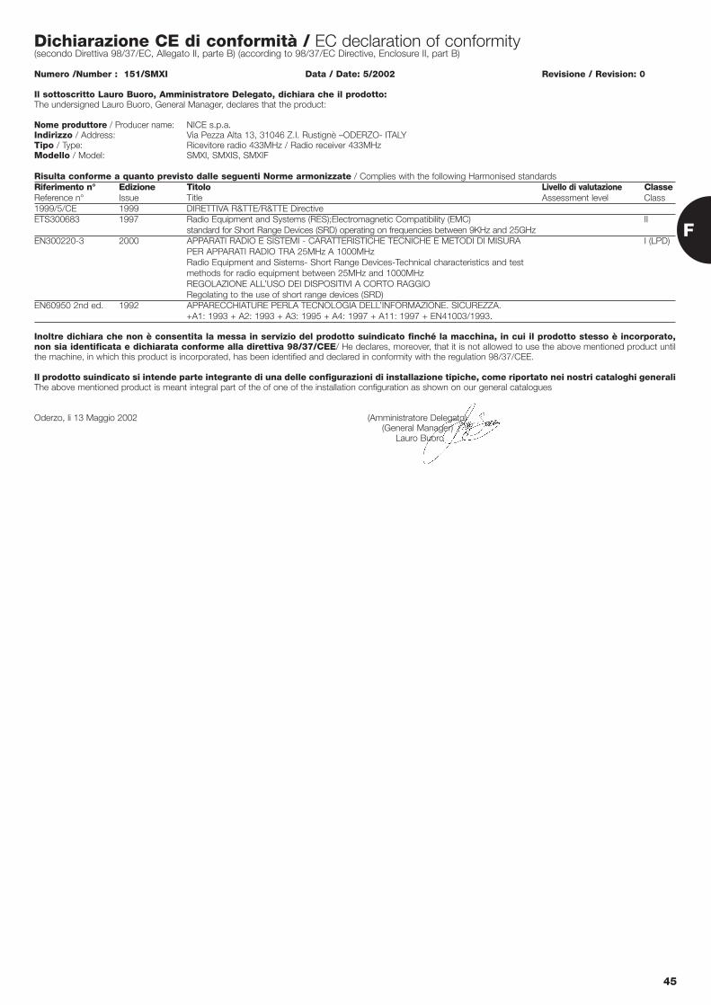
Dichiarazione CE di conformità / EC declaration of conformity(secondo Direttiva 98/37/EC, Allegato II, parte B) (according to 98/37/EC Directive, Enclosure II, part B)
Numero /Number : 151/SMXI Data / Date: 5/2002 Revisione / Revision: 0
Il sottoscritto Lauro Buoro, Amministratore Delegato, dichiara che il prodotto:The undersigned Lauro Buoro, General Manager, declares that the product:
Nome produttore / Producer name: NICE s.p.a.Indirizzo / Address: Via Pezza Alta 13, 31046 Z.I. Rustignè –ODERZO- ITALYTipo / Type: Ricevitore radio 433MHz / Radio receiver 433MHzModello / Model: SMXI, SMXIS, SMXIF
Risulta conforme a quanto previsto dalle seguenti Norme armonizzate / Complies with the following Harmonised standardsRiferimento n° Edizione Titolo Livello di valutazione ClasseReference n° Issue Title Assessment level Class1999/5/CE 1999 DIRETTIVA R&TTE/R&TTE DirectiveETS300683 1997 Radio Equipment and Systems (RES);Electromagnetic Compatibility (EMC) II
standard for Short Range Devices (SRD) operating on frequencies between 9KHz and 25GHzEN300220-3 2000 APPARATI RADIO E SISTEMI - CARATTERISTICHE TECNICHE E METODI DI MISURA I (LPD)
PER APPARATI RADIO TRA 25MHz A 1000MHzRadio Equipment and Sistems- Short Range Devices-Technical characteristics and test methods for radio equipment between 25MHz and 1000MHzREGOLAZIONE ALL’USO DEI DISPOSITIVI A CORTO RAGGIORegolating to the use of short range devices (SRD)
EN60950 2nd ed. 1992 APPARECCHIATURE PERLA TECNOLOGIA DELL’INFORMAZIONE. SICUREZZA. +A1: 1993 + A2: 1993 + A3: 1995 + A4: 1997 + A11: 1997 + EN41003/1993.
Inoltre dichiara che non è consentita la messa in servizio del prodotto suindicato finché la macchina, in cui il prodotto stesso è incorporato,non sia identificata e dichiarata conforme alla direttiva 98/37/CEE/ He declares, moreover, that it is not allowed to use the above mentioned product untilthe machine, in which this product is incorporated, has been identified and declared in conformity with the regulation 98/37/CEE.
Il prodotto suindicato si intende parte integrante di una delle configurazioni di installazione tipiche, come riportato nei nostri cataloghi generaliThe above mentioned product is meant integral part of the of one of the installation configuration as shown on our general catalogues
Oderzo, li 13 Maggio 2002 (Amministratore Delegato)(General Manager)
Lauro Buoro
F
45
46
steuerung Toröffnerrobo, thor
Hinweise:
Die vorliegende Anleitung ist nur für technisches Personalbestimmt, das für die Installation qualifiziert ist. Keine imvorliegenden Heft enthaltene Information kann als interessant fürden Endbenutzer betrachtet werden! Der Zweck dieser Zentrale ist die Steuerung elektromechanischerArbeitszylinder für die Automatisierung von Toren oderSchwingtüren; jede andere Art von Verwendung ist unzulässigund nach den geltenden Normen verboten.Es wird empfohlen, alle Anweisungen mindestens einmal vor derInstallation genau zu lesen.
!
Inhalt: S.
1 Beschreibung des Produktes 47
2 Installation 472.1 Typische Anlage 472.2 Elektrische Anschlüsse 482.2.1 Schaltplan 482.2.2 Beschreibung der Anschlüsse 482.2.3 Photozellentest 492.2.4 Überprüfung der Anschlüsse 50
3 Einstellungen 50
4 Prüfung 51
5 Betriebsarten 52
S.
6 Programmierbare Funktionen 526.1 Beschreibung der Funktionen 53
7 Was tun, um ... 54
8 Sonderzubehör 55
9 Wartung 55
10 Entsorgung 55
11 Was tun, wenn… 55
12 Technische Merkmale 55
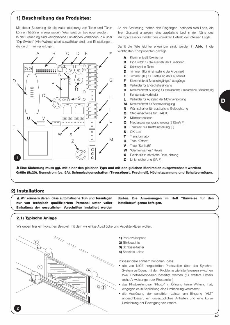
D
47
1) Beschreibung des Produktes:
Mit dieser Steuerung für die Automatisierung von Toren und Türenkönnen Töröffner in einphasigem Wechselstrom betrieben werden.In der Steuerung sind verschiedene Funktionen vorhanden, die über“Dip-Switch” (Mini-Wählschalter) auswählbar sind, und Einstellungen,die durch Trimmer erfolgen.
An der Steuerung, neben den Eingängen, befinden sich Leds, dieihren Zustand anzeigen; eine zuzügliche Led in der Nähe desMikroprozessors meldet den korrekten Betrieb der internen Logik.
Damit die Teile leichter erkennbar sind, werden in Abb. 1 diewichtigsten Komponenten gezeigt.
OK
BA C
R
D E F
G
H
I
L
M
P
S
Z
O
T
U V
Q
N
W X
Klemmenbrett fürAntenneDip-Switch für die Auswahl der FunktionenSchrittzyklus-TasteTrimmer (TL) für Einstellung der ArbeitszeitTrimmer (TP) für Einstellung der PausenzeitKlemmenbrett Steuereingänge / -ausgängeVerbinder für EndschaltereingangKlemmenbrett Ausgang für Blinkleuchte / zusätzliche BeleuchtungKondensatorverbinderVerbinder für Ausgang der Motorversorgung Klemmenbrett für StromversorgungWählschalter für zusätzliche BeleuchtungSteckanschluss für RADIOMikroprozessorNiederspannungssicherung (315mA F)Trimmer für Krafteinstellung (F)OK-Led TransformatorTriac “Öffnet”Triac “Schließt”“Gemeinsames” RelaisRelais für zusätzliche BeleuchtungLiniensicherung (5A F)
ABCDEFGHILMNOPQRSTUVWXZ1
2.1) Typische Anlage
Wir geben hier ein typisches Beispiel, mit dem wir einige Ausdrücke und Aspekte klären wollen.
Wir erinnern daran, dass automatische Tür- und Toranlagennur von technisch qualifiziertem Personal unter vollerEinhaltung der gesetzlichen Vorschriften installiert werden
dürfen. Die Anweisungen im Heft “Hinweise für denInstallateur” genau befolgen.
!
2) Installation:
2
4
3
PHOTOZELLEN
2
1
1) Photozellenpaar2) Blinkleuchte3) Schlüsseltaster4) Sensible Leiste
Insbesondere erinnern wir daran, dass:• alle von NICE hergestellten Photozellen über das Synchro-
System verfügen, mit dem Probleme wie Interferenzen zwischenzwei Photozellenpaaren beseitigt werden (für weitere Detailssiehe Anweisungen der Photozellen)
• das Photozellenpaar “Photo” in Öffnung keine Wirkung hat,wogegen es in Schließung eine Umkehrung verursacht.
• die Auslösung der sensiblen Leiste, am Eingang “ALT”angeschlossen, ein unverzügliches Anhalten und eine kurzeUmkehrung der Bewegung verursacht.
Eine Sicherung muss ggf. mit einer des gleichen Typs und mit den gleichen Merkmalen ausgewechselt werden: Größe (5x20), Nennstrom (es. 5A), Schmelzeigenschaften (T=verzögert, F=schnell), Höchstspannung und Schaltvermögen.
!
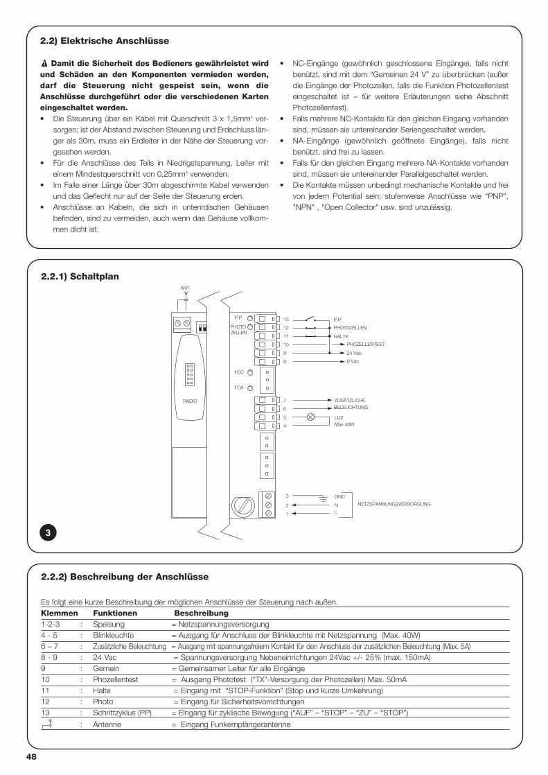
2.2.1) Schaltplan
NETZSPANNUNGSVERSORGUNG
P.P.
PHOTOZELLEN
FCA
FCC
PHOZELLENTEST
24 Vac
0 Vac
8
GND
LUXMax 40W
ANT.
PHOTOZELLEN
P.P.
HALTE11
10
9
12
13
BELEUCHTUNG
ZUSÄTZLICHE
4
5
6
L
3
1
2
7
N
RADIO
2.2) Elektrische Anschlüsse
Damit die Sicherheit des Bedieners gewährleistet wirdund Schäden an den Komponenten vermieden werden,darf die Steuerung nicht gespeist sein, wenn dieAnschlüsse durchgeführt oder die verschiedenen Karteneingeschaltet werden.• Die Steuerung über ein Kabel mit Querschnitt 3 x 1,5mm2 ver-
sorgen; ist der Abstand zwischen Steuerung und Erdschluss län-ger als 30m, muss ein Erdleiter in der Nähe der Steuerung vor-gesehen werden.
• Für die Anschlüsse des Teils in Niedrigstspannung, Leiter miteinem Mindestquerschnitt von 0,25mm2 verwenden.
• Im Falle einer Länge über 30m abgeschirmte Kabel verwendenund das Geflecht nur auf der Seite der Steuerung erden.
• Anschlüsse an Kabeln, die sich in unterirdischen Gehäusenbefinden, sind zu vermeiden, auch wenn das Gehäuse vollkom-men dicht ist.
• NC-Eingänge (gewöhnlich geschlossene Eingänge), falls nichtbenützt, sind mit dem “Gemeinen 24 V” zu überbrücken (außerdie Eingänge der Photozellen, falls die Funktion Photozellentesteingeschaltet ist – für weitere Erläuterungen siehe AbschnittPhotozellentest).
• Falls mehrere NC-Kontakte für den gleichen Eingang vorhandensind, müssen sie untereinander Seriengeschaltet werden.
• NA-Eingänge (gewöhnlich geöffnete Eingänge), falls nichtbenützt, sind frei zu lassen.
• Falls für den gleichen Eingang mehrere NA-Kontakte vorhandensind, müssen sie untereinander Parallelgeschaltet werden.
• Die Kontakte müssen unbedingt mechanische Kontakte und freivon jedem Potential sein; stufenweise Anschlüsse wie “PNP","NPN" , "Open Collector" usw. sind unzulässig.
!
2.2.2) Beschreibung der Anschlüsse
Es folgt eine kurze Beschreibung der möglichen Anschlüsse der Steuerung nach außen.Klemmen Funktionen Beschreibung1-2-3 : Speisung = Netzspannungsversorgung4 - 5 : Blinkleuchte = Ausgang für Anschluss der Blinkleuchte mit Netzspannung (Max. 40W)6 – 7 : Zusätzliche Beleuchtung = Ausgang mit spannungsfreiem Kontakt für den Anschluss der zusätzlichen Beleuchtung (Max. 5A)8 - 9 : 24 Vac = Spannungsversorgung Nebeneinrichtungen 24Vac +/- 25% (max. 150mA) 9 : Gemein = Gemeinsamer Leiter für alle Eingänge10 : Phozellentest = Ausgang Phototest (“TX”-Versorgung der Photozellen) Max. 50mA11 : Halte = Eingang mit “STOP-Funktion” (Stop und kurze Umkehrung)12 : Photo = Eingang für Sicherheitsvorrichtungen13 : Schrittzyklus (PP) = Eingang für zyklische Bewegung (“AUF” – “STOP” – “ZU” – “STOP”)
: Antenne = Eingang Funkempfängerantenne
3
48
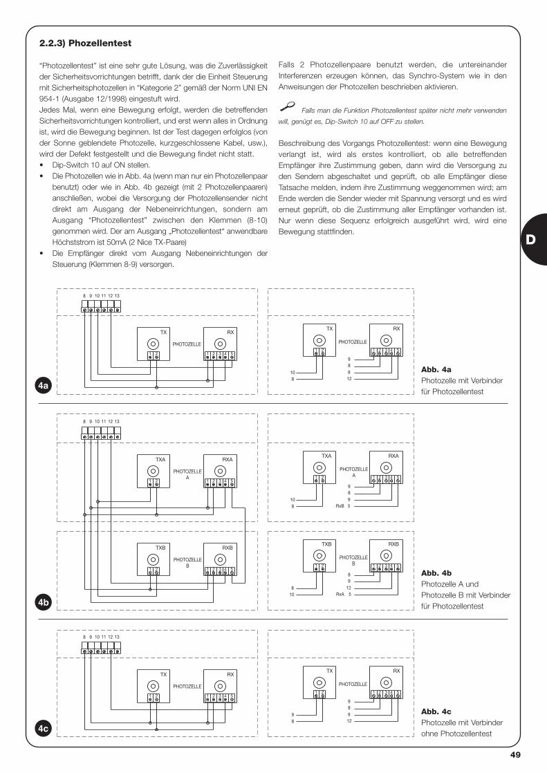
2.2.3) Phozellentest
“Photozellentest” ist eine sehr gute Lösung, was die Zuverlässigkeitder Sicherheitsvorrichtungen betrifft, dank der die Einheit Steuerungmit Sicherheitsphotozellen in “Kategorie 2” gemäß der Norm UNI EN954-1 (Ausgabe 12/1998) eingestuft wird.Jedes Mal, wenn eine Bewegung erfolgt, werden die betreffendenSicherheitsvorrichtungen kontrolliert, und erst wenn alles in Ordnungist, wird die Bewegung beginnen. Ist der Test dagegen erfolglos (vonder Sonne geblendete Photozelle, kurzgeschlossene Kabel, usw.),wird der Defekt festgestellt und die Bewegung findet nicht statt.• Dip-Switch 10 auf ON stellen. • Die Photozellen wie in Abb. 4a (wenn man nur ein Photozellenpaar
benutzt) oder wie in Abb. 4b gezeigt (mit 2 Photozellenpaaren)anschließen, wobei die Versorgung der Photozellensender nichtdirekt am Ausgang der Nebeneinrichtungen, sondern amAusgang “Photozellentest” zwischen den Klemmen (8-10)genommen wird. Der am Ausgang „Photozellentest“ anwendbareHöchststrom ist 50mA (2 Nice TX-Paare)
• Die Empfänger direkt vom Ausgang Nebeneinrichtungen derSteuerung (Klemmen 8-9) versorgen.
Falls 2 Photozellenpaare benutzt werden, die untereinanderInterferenzen erzeugen können, das Synchro-System wie in denAnweisungen der Photozellen beschrieben aktivieren.
Falls man die Funktion Photozellentest später nicht mehr verwenden
will, genügt es, Dip-Switch 10 auf OFF zu stellen.
Beschreibung des Vorgangs Photozellentest: wenn eine Bewegungverlangt ist, wird als erstes kontrolliert, ob alle betreffendenEmpfänger ihre Zustimmung geben, dann wird die Versorgung zuden Sendern abgeschaltet und geprüft, ob alle Empfänger dieseTatsache melden, indem ihre Zustimmung weggenommen wird; amEnde werden die Sender wieder mit Spannung versorgt und es wirderneut geprüft, ob die Zustimmung aller Empfänger vorhanden ist.Nur wenn diese Sequenz erfolgreich ausgeführt wird, wird eineBewegung stattfinden.
3 4 5
RX
1 2
9
98
TX
21
98 12
RX
4 5
PHOTOZELLE
321
TX
PHOTOZELLE
21
1311 1298 10
RxA
RxB
5421 3
1298
PHOTOZELLEB
5
RXBTXB
21
810
RXB
4 5321
TXB
PHOTOZELLEB
21
5421 3
98
PHOTOZELLEA
59
RXATXA
21
810
4 5
RXA
1311 12
2 31
TXA
PHOTOZELLEA
1 2
98 10
12 13111098
RX
3 4 51 2
9
912
8
PHOTOZELLE
1 2
108
RX
3 4 51 2
TX
1 2
PHOTOZELLE
TX
4a
4b
4c
Abb. 4aPhotozelle mit Verbinder für Photozellentest
Abb. 4bPhotozelle A undPhotozelle B mit Verbinder für Photozellentest
Abb. 4cPhotozelle mit Verbinder ohne Photozellentest
D
49
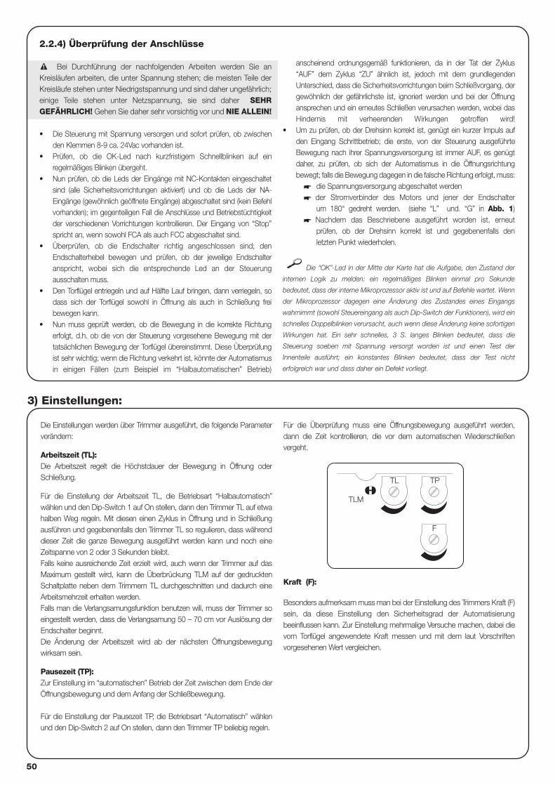
2.2.4) Überprüfung der Anschlüsse
Bei Durchführung der nachfolgenden Arbeiten werden Sie anKreisläufen arbeiten, die unter Spannung stehen; die meisten Teile derKreisläufe stehen unter Niedrigstspannung und sind daher ungefährlich;einige Teile stehen unter Netzspannung, sie sind daher SEHRGEFÄHRLICH! Gehen Sie daher sehr vorsichtig vor und NIE ALLEIN!
• Die Steuerung mit Spannung versorgen und sofort prüfen, ob zwischenden Klemmen 8-9 ca. 24Vac vorhanden ist.
• Prüfen, ob die OK-Led nach kurzfristigem Schnellblinken auf einregelmäßiges Blinken übergeht.
• Nun prüfen, ob die Leds der Eingänge mit NC-Kontakten eingeschaltetsind (alle Sicherheitsvorrichtungen aktiviert) und ob die Leds der NA-Eingänge (gewöhnlich geöffnete Eingänge) abgeschaltet sind (kein Befehlvorhanden); im gegenteiligen Fall die Anschlüsse und Betriebstüchtigkeitder verschiedenen Vorrichtungen kontrollieren. Der Eingang von “Stop”spricht an, wenn sowohl FCA als auch FCC abgeschaltet sind.
• Überprüfen, ob die Endschalter richtig angeschlossen sind; denEndschalterhebel bewegen und prüfen, ob der jeweilige Endschalteranspricht, wobei sich die entsprechende Led an der Steuerungausschalten muss.
• Den Torflügel entriegeln und auf Hälfte Lauf bringen, dann verriegeln, sodass sich der Torflügel sowohl in Öffnung als auch in Schließung freibewegen kann.
• Nun muss geprüft werden, ob die Bewegung in die korrekte Richtungerfolgt, d.h. ob die von der Steuerung vorgesehene Bewegung mit dertatsächlichen Bewegung der Torflügel übereinstimmt. Diese Überprüfungist sehr wichtig; wenn die Richtung verkehrt ist, könnte der Automatismusin einigen Fällen (zum Beispiel im “Halbautomatischen” Betrieb)
anscheinend ordnungsgemäß funktionieren, da in der Tat der Zyklus“AUF” dem Zyklus “ZU” ähnlich ist, jedoch mit dem grundlegendenUnterschied, dass die Sicherheitsvorrichtungen beim Schließvorgang, dergewöhnlich der gefährlichste ist, ignoriert werden und bei der Öffnungansprechen und ein erneutes Schließen verursachen werden, wobei dasHindernis mit verheerenden Wirkungen getroffen wird!
• Um zu prüfen, ob der Drehsinn korrekt ist, genügt ein kurzer Impuls aufden Eingang Schrittbetrieb; die erste, von der Steuerung ausgeführteBewegung nach ihrer Spannungsversorgung ist immer AUF, es genügtdaher, zu prüfen, ob sich der Automatismus in die Öffnungsrichtungbewegt; falls die Bewegung dagegen in die falsche Richtung erfolgt, muss:
� die Spannungsversorgung abgeschaltet werden� der Stromverbinder des Motors und jener der Endschalter
um 180° gedreht werden. (siehe “L” und. “G” in Abb. 1)� Nachdem das Beschriebene ausgeführt worden ist, erneut
prüfen, ob der Drehsinn korrekt ist und gegebenenfalls denletzten Punkt wiederholen.
Die “OK”-Led in der Mitte der Karte hat die Aufgabe, den Zustand der
internen Logik zu melden: ein regelmäßiges Blinken einmal pro Sekunde
bedeutet, dass der interne Mikroprozessor aktiv ist und auf Befehle wartet. Wenn
der Mikroprozessor dagegen eine Änderung des Zustandes eines Eingangs
wahrnimmt (sowohl Steuereingang als auch Dip-Switch der Funktionen), wird ein
schnelles Doppelblinken verursacht, auch wenn diese Änderung keine sofortigen
Wirkungen hat. Ein sehr schnelles, 3 S. langes Blinken bedeutet, dass die
Steuerung soeben mit Spannung versorgt worden ist und einen Test der
Innenteile ausführt; ein konstantes Blinken bedeutet, dass der Test nicht
erfolgreich war und dass daher ein Defekt vorliegt.
!
Die Einstellungen werden über Trimmer ausgeführt, die folgende Parameterverändern:
Arbeitszeit (TL): Die Arbeitszeit regelt die Höchstdauer der Bewegung in Öffnung oderSchließung.
Für die Einstellung der Arbeitszeit TL, die Betriebsart “Halbautomatisch”wählen und den Dip-Switch 1 auf On stellen, dann den Trimmer TL auf etwahalben Weg regeln. Mit diesen einen Zyklus in Öffnung und in Schließungausführen und gegebenenfalls den Trimmer TL so regulieren, dass währenddieser Zeit die ganze Bewegung ausgeführt werden kann und noch eineZeitspanne von 2 oder 3 Sekunden bleibt.Falls keine ausreichende Zeit erzielt wird, auch wenn der Trimmer auf dasMaximum gestellt wird, kann die Überbrückung TLM auf der gedrucktenSchaltplatte neben dem Trimmern TL durchgeschnitten und dadurch eineArbeitsmehrzeit erhalten werden.Falls man die Verlangsamungsfunktion benutzen will, muss der Trimmer soeingestellt werden, dass die Verlangsamung 50 – 70 cm vor Auslösung derEndschalter beginnt.Die Änderung der Arbeitszeit wird ab der nächsten Öffnungsbewegungwirksam sein.
Pausezeit (TP):Zur Einstellung im “automatischen” Betrieb der Zeit zwischen dem Ende derÖffnungsbewegung und dem Anfang der Schließbewegung.
Für die Einstellung der Pausezeit TP, die Betriebsart “Automatisch” wählenund den Dip-Switch 2 auf On stellen, dann den Trimmer TP beliebig regeln.
Für die Überprüfung muss eine Öffnungsbewegung ausgeführt werden,dann die Zeit kontrollieren, die vor dem automatischen Wiederschließenvergeht.
Kraft (F):
Besonders aufmerksam muss man bei der Einstellung des Trimmers Kraft (F)sein, da diese Einstellung den Sicherheitsgrad der Automatisierungbeeinflussen kann. Zur Einstellung mehrmalige Versuche machen, dabei dievom Torflügel angewendete Kraft messen und mit dem laut Vorschriftenvorgesehenen Wert vergleichen.
3) Einstellungen:
F
TL TP
TLM
50
Nachdem die Überprüfungen und Einstellungen beendet sind, kann man auf die Prüfung der Anlage übergehen.
Die Automatisierung muss von erfahrenem Fachpersonal geprüft werden, das die vorzusehenden Tests je nachvorhandenem Risiko festzulegen hat.
Die Prüfung ist das Wichtigste bei der Durchführung der ganzen Automatisierung. Jedes einzelne Teil wie Motor, Notstop, Photozellen usw.kann eine spezielle Prüfung erfordern, daher wird empfohlen, sich an die Verfahren in den jeweiligen Anleitungen zu halten.
Für die Prüfung der Steuerung sind der Reihe nach folgende Schritte auszuführen:
1. Auswahl der Funktionen: • Den Dip-Switch 1 auf ON stellen (halbautomatischer Betrieb)• Alle anderen Dip-Switch auf OFF stellen.
2. Auf die Steuertaste “Schrittbetrieb” drücken und prüfen, ob:• Eine Öffnungsbewegung beginnt• Sich die Blinkleuchte aktiviert• Die Bewegung anhält, wenn der Endschalter FCA in Öffnung erreicht wird.
3. Wieder auf die Steuertaste “Schrittbetrieb” drücken und prüfen, ob• Eine Schließbewegung beginnt• Sich die Blinkleuchte aktiviert• Die Bewegung anhält, wenn der Endschalter FCC in Schließung erreicht wird.
4. Eine Bewegung in Öffnung beginnen und prüfen, ob das Ansprechen einer Vorrichtung während der Bewegung:• Die am Eingang Stop angeschlossen ist, ein umgehendes Anhalten der Bewegung verursacht und eine kurze Umkehrung• Die am Eingang Photo angeschlossen ist, keine Wirkung hat
5. Eine Bewegung in Schließung beginnen und prüfen, ob das Ansprechen einer Vorrichtung während der Bewegung:• Die am Eingang Stop angeschlossen ist, ein umgehendes Anhalten der Bewegung verursacht und eine kurze Umkehrung• Die am Eingang Photo angeschlossen ist, das Anhalten und die Umkehrung der Bewegung verursacht
6. Auf Taste “Schrittbetrieb” drücken und prüfen, ob jede Aktivierung des Eingangs einen Schritt in der folgenden Sequenz verursacht:• “Auf” – “Stop” – “Zu” – “Stop”
7. Falls die Funktion Photozellentest benützt wird, die Effizienz des Test überprüfen:• Die Photozelle “Photo” abblenden, dann eine Bewegung beginnen und prüfen, dass diese nicht ausgeführt wird• Den Kontakt der Photozelle “Photo” kurzschließen, dann eine Bewegung beginnen und prüfen, dass diese nicht ausgeführt wird.
8. Die Tests für die Messung der Aufprallkraft durchführen, wie von der Vorschrift EN 12445 vorgesehen.
Werden am Ende der Prüfung weitere Funktionen aktiviert, welche die Sicherheit der Anlage reduzieren können, so sind diese Funktionenbesonders zu prüfen.
!
4) Prüfung
D
51
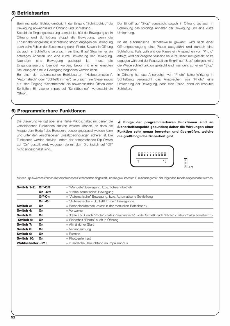
52
5) Betriebsarten
Beim manuellen Betrieb ermöglicht der Eingang “Schrittbetrieb” dieBewegung abwechselnd in Öffnung und Schließung. Sobald die Eingangssteuerung beendet ist, hält die Bewegung an. InÖffnung und Schließung stoppt die Bewegung, wenn dieEndschalter eingreifen; in Schließung stoppt dagegen die Bewegungauch beim Fehlen der Zustimmung durch Photo. Sowohl in Öffnungals auch in Schließung verursacht ein Eingriff auf Stop immer einsofortiges Anhalten und eine kurze Umkehrung der Bewegung.Nachdem eine Bewegung gestoppt ist, muss dieEingangssteuerung beendet werden, bevor mit einer erneutenSteuerung eine neue Bewegung begonnen werden kann.Bei einer der automatischen Betriebsarten “(Halbautomatisch”,“Automatisch” oder “Schließt immer”) verursacht ein Steuerimpulsauf den Eingang “Schrittbetrieb” ein abwechselndes Öffnen oderSchließen. Ein zweiter Impuls auf “Schrittbetrieb” verursacht ein“Stop”.
Der Eingriff auf “Stop” verursacht sowohl in Öffnung als auch inSchließung das sofortige Anhalten der Bewegung und eine kurzeUmkehrung.
Ist die automatische Betriebsweise gewählt, wird nach einerÖffnungsbewegung eine Pause ausgeführt und danach eineSchließung. Falls während der Pause ein Ansprechen von “Photo”erfolgt, wird der Zeitgeber auf eine neue Pausezeit rückgestellt; solltedagegen während der Pausezeit ein Eingriff auf “Stop” erfolgen, wirddie Wiederschließfunktion gelöscht und man geht auf einen “Stop”Zustand über.In Öffnung hat das Ansprechen von “Photo” keine Wirkung; inSchließung verursacht das Ansprechen von “Photo” eineUmkehrung der Bewegung, dann eine Pause, dann ein erneutesSchließen.
Die Steuerung verfügt über eine Reihe Mikroschalter, mit denen dieverschiedenen Funktionen aktiviert werden können, so dass dieAnlage dem Bedarf des Benutzers besser angepasst werden kannund unter den verschiedenen Einsatzbedingungen sicherer ist. DieFunktionen werden aktiviert, indem der entsprechende Dip-Switchauf “On” gestellt wird, wogegen sie mit dem Dip-Switch auf “Off”nicht eingeschaltet sind..
Einige der programmierbaren Funktionen sind anSicherheitsaspekte gebunden; daher die Wirkungen einerFunktion sehr genau bewerten und überprüfen, welchedie größtmögliche Sicherheit gibt
!
Mit den Dip-Switches können die verschiedenen Betriebsarten eingestellt und die gewünschten Funktionen gemäß der folgenden Tabelle eingeschaltet werden:
Switch 1-2: Off-Off = “Manuelle” Bewegung, bzw. TotmannbetriebOn -Off = “Halbautomatische” BewegungOff-On = “Automatische” Bewegung, bzw. Automatische SchließungOn -On = “Automatische + Schließt Immer” Bewegunge
Switch 3: On = Wohnblockbetrieb <nicht in der manuellen Betriebsart>Switch 4: On = VorwarnenSwitch 5: On = Schließt 5 S. nach “Photo” < falls in “automatisch” > oder Schließt nach “Photo” < falls in “halbautomatisch” >Switch 6: On = Sicherheit “Photo” auch in ÖffnungSwitch 7: On = Allmählicher StartSwitch 8: On = VerlangsamungSwitch 9: On = BremseSwitch 10: On = PhotozellentestWählschalter JP1: = zusätzliche Beleuchtung im Impulsmodus
6) Programmierbare Funktionen
101
JP1
D
53
6.1) Beschreibung der Funktionen
Wir geben nun eine kurze Beschreibung der Funktionen, die eingeschaltet werden können, indem der entsprechende Dip-Switch auf “On” gestellt wird.
Switch 1-2: Off-Off = “Manuelle” Bewegung, bzw. TotmannbetriebOn-Off = “Halbautomatische Bewegung”Off-On = “Automatische” Bewegung, bzw. Automatische SchließungOn-On = “Automatische + Schließt Immer” Bewegung
In der “manuellen” Betriebsart wird die Bewegung nur bis zum Vorhandensein der Steuerung (Taste gedrückt) ausgeführt.In der “halbautomatischen” Betriebsart genügt ein Steuerimpuls, damit die gesamte Bewegung bis zum Ablauf der Arbeitszeit oder Erreichendes Endschalters ausgeführt wird. In der “automatischen” Betriebsart folgt nach einer Öffnung eine Pause und dann ein automatischesSchließen.Die Funktion “Schließt immer” greift nach einem Stromausfall ein; falls das offene Tor wahrgenommen wird, wird automatisch einSchließvorgang gestartet, dem ein 5 Sekunden langes Vorwarnen vorausgeht
Switch 3: On = Wohnblockbetrieb (nicht in der manuellen Betriebsart) Im Wohnblockbetrieb kann nach dem Start einer Öffnungsbewegung die Bewegung nicht mehr durch andere Steuerimpulse aufSchrittbetrieb bis zum Ende der Öffnungsbewegung unterbrochen werden. In der Schließbewegung verursacht ein neuer Steuerimpuls das Anhalten und die Umkehrung der Öffnungsbewegung.
Switch 4: On = VorwarnenBei Steuerimpuls wird zuerst das Blinklicht aktiviert und nach 5 S. (2 S. in manueller Betriebsart) beginnt die Bewegung.
Switch 5: On = Schließt 5 S. nach “Photo” < falls in “automatisch” > oder Schließt nach “Photo” <falls in “halbautomatisch” >Mit dieser Funktion, falls in der “Automatischen” Betriebsart, kann das Tor nur die für das Durchfahren notwendige Zeit geöffnet gehaltenwerden; nach dem Ansprechen von “Photo” wird die Bewegung angehalten. 5 S. danach wird automatisch eine Bewegung in Schließungbeginnen. Falls in der halbautomatischen Betriebsart, aktiviert ein Ansprechen von “Photo” während der Schließbewegung das automatischeSchließen je nach eingestellter Pausezeit.
Switch 6: On = Sicherheit “Photo” auch in ÖffnungGewöhnlich ist die Sicherheit “Photo” nur bei der Schließung aktiviert, wenn der Dip-Switch 6 auf “On” gestellt wird, verursacht dieSicherheitsvorrichtung auch in Öffnung eine Unterbrechung der Bewegung.In “halbautomatisch” oder “automatisch” erfolgt erneut eine Bewegung, wenn die Photozelle wieder frei ist.
Switch 7: On = Allmählicher StartDer Beginn der Bewegung wird stufenweise ausgeführt, wodurch ruckartige Bewegungen der Automatisierung verhindert werden.
Switch 8: On = Verlangsamung Die Verlangsamung ist eine Geschwindigkeitsreduzierung von 30% der Nenngeschwindigkeit, so dass die Aufprallkraft im Öffnungs- undSchließbereich des Tors verringert wird.
Nach der Aktivierung der Funktion Verlangsamung muss der Trimmer Arbeitszeit (TL) betätigt werden, da der Beginn der Verlangsamung andie eingestellte Arbeitszeit gebunden ist. Daher die Arbeitszeit so regeln, dass die Verlangsamung ca. 50-70 cm vor der Auslösung derEndschalter beginnt.
Neben der Reduzierung der Geschwindigkeit verringert die Verlangsamungsfunktion den Drehmoment des Motors um 70%..
Bei Automatisierungen, für die ein hoher Drehmoment erforderlich ist, könnte diese Reduzierung das sofortige Anhalten des Motors verursachen.
Switch 9: On = BremseAm Ende der Bewegung wird ein Bremsvorgang am Motor ausgeführt, anfänglich nur schwach, dann kräftiger, so dass das Tor schnell, abernicht ruckartig angehalten wird.
Switch 10: On = PhototestMit dieser Funktion kann bei Beginn einer jeden Bewegung die Betriebstüchtigkeit der Photozellen kontrolliert werden. Siehe AbschnittPHOTOZELLENTEST.
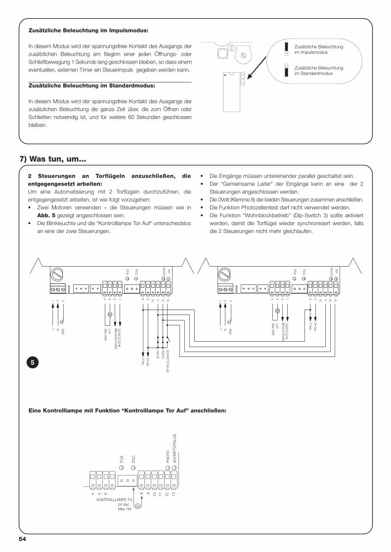
2 Steuerungen an Torflügeln anzuschließen, dieentgegengesetzt arbeiten:Um eine Automatisierung mit 2 Torflügeln durchzuführen, dieentgegengesetzt arbeiten, ist wie folgt vorzugehen:• Zwei Motoren verwenden – die Steuerungen müssen wie in
Abb. 5 gezeigt angeschlossen sein.• Die Blinkleuchte und die “Kontrolllampe Tor Auf“ unterschiedslos
an eine der zwei Steuerungen.
• Die Eingänge müssen untereinander parallel geschaltet sein. • Der “Gemeinsame Leiter” der Eingänge kann an eine der 2
Steuerungen angeschlossen werden.• Die 0Volt (Klemme 8) der beiden Steuerungen zusammen anschließen.• Die Funktion Photozellentest darf nicht verwendet werden.• Die Funktion “Wohnblockbetrieb” (Dip-Switch 3) sollte aktiviert
werden, damit die Torflügel wieder synchronisiert werden, fallsdie 2 Steuerungen nicht mehr gleichlaufen.
7) Was tun, um...
N
7
21 3
L
654
ZUS
ÄTZLIC
HE
BE
LEU
CH
TUN
G
13129 10 11H
ALTE
P.P.
PHO
TO
Max 40W
LUX
GN
D
8
0 Vac
24 Vac
FCC
FCA
PHO
TO
SC
HR
ITTZYK
LUS
11
0 Vac
24 Vac
BELEUC
HTU
NG
Max 40W
GN
D3
NL
1 2
LUX
ZUSÄTZLIC
HE
54 76 8 9 10
FCA
FCC
12 13PH
OTO
P.P.
5
Zusätzliche Beleuchtung im Impulsmodus:
In diesem Modus wird der spannungsfreie Kontakt des Ausgangs derzusätzlichen Beleuchtung am Beginn einer jeden Öffnungs- oderSchließbewegung 1 Sekunde lang geschlossen bleiben, so dass einemeventuellen, externen Timer ein Steuerimpuls gegeben werden kann.
Zusätzliche Beleuchtung im Standardmodus:
In diesem Modus wird der spannungsfreie Kontakt des Ausgangs derzusätzlichen Beleuchtung die ganze Zeit über, die zum Öffnen oderSchließen notwendig ist, und für weitere 60 Sekunden geschlossenbleiben.
Zusätzliche Beleuchtungim Impulsmodus
Zusätzliche Beleuchtungim Standardmodus
FCC
FCA
SC
HR
ITTZ
YK
LUS
54 6 1198 10 12 13
24 VacKONTROLLLAMPE T.A.
Max 1W
PH
OTO
Eine Kontrolllampe mit Funktion “Kontrolllampe Tor Auf” anschließen:
54
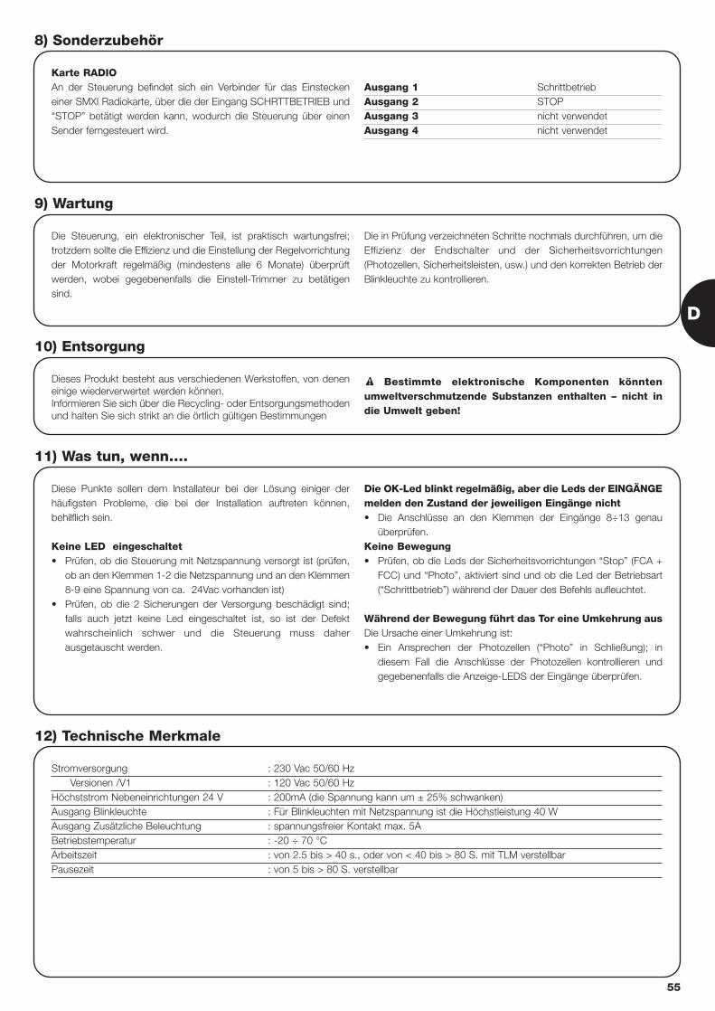
Karte RADIOAn der Steuerung befindet sich ein Verbinder für das Einsteckeneiner SMXI Radiokarte, über die der Eingang SCHRTTBETRIEB und“STOP” betätigt werden kann, wodurch die Steuerung über einenSender ferngesteuert wird.
Ausgang 1 SchrittbetriebAusgang 2 STOPAusgang 3 nicht verwendetAusgang 4 nicht verwendet
8) Sonderzubehör
Die Steuerung, ein elektronischer Teil, ist praktisch wartungsfrei;trotzdem sollte die Effizienz und die Einstellung der Regelvorrichtungder Motorkraft regelmäßig (mindestens alle 6 Monate) überprüftwerden, wobei gegebenenfalls die Einstell-Trimmer zu betätigensind.
Die in Prüfung verzeichneten Schritte nochmals durchführen, um dieEffizienz der Endschalter und der Sicherheitsvorrichtungen(Photozellen, Sicherheitsleisten, usw.) und den korrekten Betrieb derBlinkleuchte zu kontrollieren.
9) Wartung
Dieses Produkt besteht aus verschiedenen Werkstoffen, von deneneinige wiederverwertet werden können. Informieren Sie sich über die Recycling- oder Entsorgungsmethodenund halten Sie sich strikt an die örtlich gültigen Bestimmungen
Bestimmte elektronische Komponenten könntenumweltverschmutzende Substanzen enthalten – nicht indie Umwelt geben!
!
10) Entsorgung
Diese Punkte sollen dem Installateur bei der Lösung einiger derhäufigsten Probleme, die bei der Installation auftreten können,behilflich sein.
Keine LED eingeschaltet• Prüfen, ob die Steuerung mit Netzspannung versorgt ist (prüfen,
ob an den Klemmen 1-2 die Netzspannung und an den Klemmen8-9 eine Spannung von ca. 24Vac vorhanden ist)
• Prüfen, ob die 2 Sicherungen der Versorgung beschädigt sind;falls auch jetzt keine Led eingeschaltet ist, so ist der Defektwahrscheinlich schwer und die Steuerung muss daherausgetauscht werden.
Die OK-Led blinkt regelmäßig, aber die Leds der EINGÄNGEmelden den Zustand der jeweiligen Eingänge nicht • Die Anschlüsse an den Klemmen der Eingänge 8÷13 genau
überprüfen.Keine Bewegung• Prüfen, ob die Leds der Sicherheitsvorrichtungen “Stop” (FCA +
FCC) und “Photo”, aktiviert sind und ob die Led der Betriebsart(“Schrittbetrieb”) während der Dauer des Befehls aufleuchtet.
Während der Bewegung führt das Tor eine Umkehrung aus Die Ursache einer Umkehrung ist: • Ein Ansprechen der Photozellen (“Photo” in Schließung); in
diesem Fall die Anschlüsse der Photozellen kontrollieren undgegebenenfalls die Anzeige-LEDS der Eingänge überprüfen.
11) Was tun, wenn….
Stromversorgung : 230 Vac 50/60 HzVersionen /V1 : 120 Vac 50/60 Hz
Höchststrom Nebeneinrichtungen 24 V : 200mA (die Spannung kann um ± 25% schwanken)Ausgang Blinkleuchte : Für Blinkleuchten mit Netzspannung ist die Höchstleistung 40 WAusgang Zusätzliche Beleuchtung : spannungsfreier Kontakt max. 5ABetriebstemperatur : -20 ÷ 70 °CArbeitszeit : von 2.5 bis > 40 s., oder von < 40 bis > 80 S. mit TLM verstellbarPausezeit : von 5 bis > 80 S. verstellbar
12) Technische Merkmale
D
55

smxi Funkempfänger
Beschreibung des Produktes
Die Besonderheit dieses Funkempfängers liegt in demErkennungscode, der für jeden Sender unterschiedlich ist (zudemändert er sich nach jedem Gebrauch). Damit der Empfänger einenbestimmten Sender erkennt, muss der Erkennungscode gespeichertwerden. Dieser Vorgang wird für jeden Sender, der zur Steuerung derSteuerzentrale benutzt werden soll, einzeln wiederholt.
Im Empfänger können bis max. 256 Sender gespeichert werden. Ein
einzelner Sender kann nicht gelöscht werden, die Codenummern können nur
alle gleichzeitig gelöscht werden..
In der Speicherphase der Codenummer des Senders stehen 2Möglichkeiten zur Auswahl:
Art I. Jede Taste des Senders aktiviert den entsprechendenAusgang des Empfängers, d.h. die Taste 1 aktiviert Ausgang 1, Taste2 aktiviert Ausgang 2, usw. In diesem Fall gibt es nur eineSpeicherphase für jeden Sender. Während dieser Phase ist esunwichtig, welche Taste gedrückt wird, es wird nur eine einzigeSpeicherstelle besetzt.Art II. Jeder Taste des Senders kann ein bestimmter Ausgang desEmpfängers zugeordnet werden, z.B. Taste 1 aktiviert Ausgang 2,Taste 2 aktiviert Ausgang 1 usw. In diesem Fall muss der Sendergespeichert werden, indem man die gewünschte Taste für jedenAusgang, der aktiviert werden soll, drückt. Natürlich kann jede Tastenur einen einzigen Ausgang aktivieren, während derselbe Ausgangdurch Drücken mehrerer Tasten aktiviert werden kann. Für jede Tastewird nur eine Speicherstelle belegt.
Installieren einer Antenne
Für einen einwandfreien Betrieb muss der Empfänger mit einer ABF-oder ABFKIT-Antenne ausgestattet werden; ohne Antenne ist dieLeistung auf wenige Meter begrenzt. Die Antenne muss so hoch wiemöglich angebracht werden; wenn Strukturen aus Metall oderStahlbeton vorhanden sind, installieren Sie die Antenne über diesenStrukturen. Wenn das zur Antenne gehörige Kabel zu kurz ist,benutzen Sie ein Koaxialkabel mit 50 Ohm Impedanz (z.B. RG58 mitniedrigem Verlust), das Kabel darf nicht länger als 10 m.
Wenn die Antenne nicht auf einer ebenen Unterlage (Wand) montiertwird, kann die Klemme des Geflechts geerdet werden, um einegrößere Leistung zu gewährleisten. Natürlich muss die Erdungsachgemäß in der Nähe ausgeführt werden. Sollte die Montage einerABF- oder ABFKIT-Antenne unmöglich sein, können guteErgebnisse mit der dem Empfänger beiliegenden Leitung alsAntenne erzielt werden. Diese Leitung muss ausgebreitet, in dervollen Länge montiert.
56
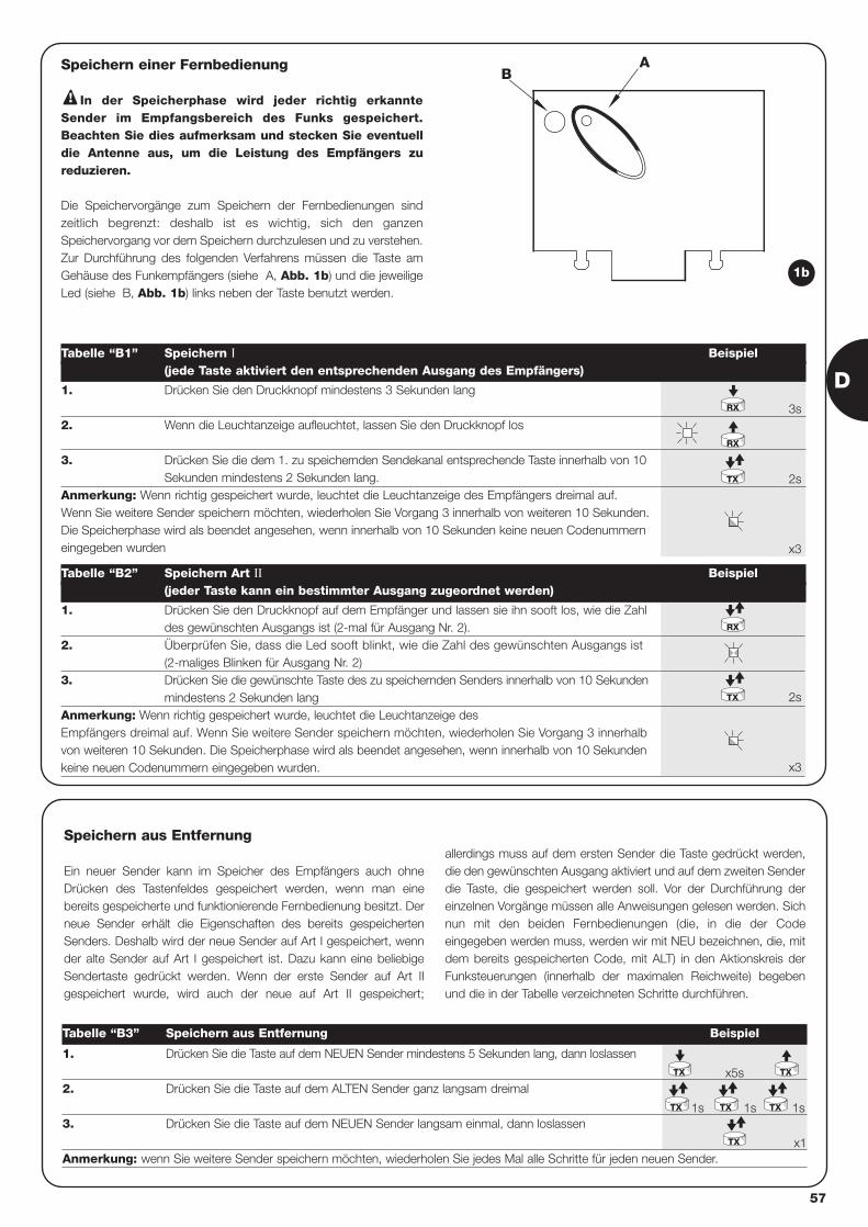
AB
Speichern einer Fernbedienung
In der Speicherphase wird jeder richtig erkannteSender im Empfangsbereich des Funks gespeichert.Beachten Sie dies aufmerksam und stecken Sie eventuelldie Antenne aus, um die Leistung des Empfängers zureduzieren.
Die Speichervorgänge zum Speichern der Fernbedienungen sindzeitlich begrenzt: deshalb ist es wichtig, sich den ganzenSpeichervorgang vor dem Speichern durchzulesen und zu verstehen.Zur Durchführung des folgenden Verfahrens müssen die Taste amGehäuse des Funkempfängers (siehe A, Abb. 1b) und die jeweiligeLed (siehe B, Abb. 1b) links neben der Taste benutzt werden.
!
3s
2s
x3
2s
x3
1. Drücken Sie den Druckknopf mindestens 3 Sekunden lang
2. Wenn die Leuchtanzeige aufleuchtet, lassen Sie den Druckknopf los
3. Drücken Sie die dem 1. zu speichernden Sendekanal entsprechende Taste innerhalb von 10Sekunden mindestens 2 Sekunden lang.
Anmerkung: Wenn richtig gespeichert wurde, leuchtet die Leuchtanzeige des Empfängers dreimal auf.Wenn Sie weitere Sender speichern möchten, wiederholen Sie Vorgang 3 innerhalb von weiteren 10 Sekunden.Die Speicherphase wird als beendet angesehen, wenn innerhalb von 10 Sekunden keine neuen Codenummerneingegeben wurden
Tabelle “B1” Speichern I Beispiel(jede Taste aktiviert den entsprechenden Ausgang des Empfängers)
1. Drücken Sie den Druckknopf auf dem Empfänger und lassen sie ihn sooft los, wie die Zahldes gewünschten Ausgangs ist (2-mal für Ausgang Nr. 2).
2. Überprüfen Sie, dass die Led sooft blinkt, wie die Zahl des gewünschten Ausgangs ist (2-maliges Blinken für Ausgang Nr. 2)
3. Drücken Sie die gewünschte Taste des zu speichernden Senders innerhalb von 10 Sekundenmindestens 2 Sekunden lang
Anmerkung: Wenn richtig gespeichert wurde, leuchtet die Leuchtanzeige des Empfängers dreimal auf. Wenn Sie weitere Sender speichern möchten, wiederholen Sie Vorgang 3 innerhalbvon weiteren 10 Sekunden. Die Speicherphase wird als beendet angesehen, wenn innerhalb von 10 Sekundenkeine neuen Codenummern eingegeben wurden.
Tabelle “B2” Speichern Art II Beispiel(jeder Taste kann ein bestimmter Ausgang zugeordnet werden)
RX
RX
TX
TX
RX
1b
x5s
1s 1s 1s
x1
1. Drücken Sie die Taste auf dem NEUEN Sender mindestens 5 Sekunden lang, dann loslassen
2. Drücken Sie die Taste auf dem ALTEN Sender ganz langsam dreimal
3. Drücken Sie die Taste auf dem NEUEN Sender langsam einmal, dann loslassen
Anmerkung: wenn Sie weitere Sender speichern möchten, wiederholen Sie jedes Mal alle Schritte für jeden neuen Sender.
Tabelle “B3” Speichern aus Entfernung Beispiel
TX
TX TX TX
TX
TX
Speichern aus Entfernung
Ein neuer Sender kann im Speicher des Empfängers auch ohneDrücken des Tastenfeldes gespeichert werden, wenn man einebereits gespeicherte und funktionierende Fernbedienung besitzt. Derneue Sender erhält die Eigenschaften des bereits gespeichertenSenders. Deshalb wird der neue Sender auf Art I gespeichert, wennder alte Sender auf Art I gespeichert ist. Dazu kann eine beliebigeSendertaste gedrückt werden. Wenn der erste Sender auf Art IIgespeichert wurde, wird auch der neue auf Art II gespeichert;
allerdings muss auf dem ersten Sender die Taste gedrückt werden,die den gewünschten Ausgang aktiviert und auf dem zweiten Senderdie Taste, die gespeichert werden soll. Vor der Durchführung dereinzelnen Vorgänge müssen alle Anweisungen gelesen werden. Sichnun mit den beiden Fernbedienungen (die, in die der Codeeingegeben werden muss, werden wir mit NEU bezeichnen, die, mitdem bereits gespeicherten Code, mit ALT) in den Aktionskreis derFunksteuerungen (innerhalb der maximalen Reichweite) begebenund die in der Tabelle verzeichneten Schritte durchführen.
D
57

58
FLOR VERY VR FLO VERY VE SMILOTasten 1 – 2 - 4 2 1 – 2 - 4 2 2 - 4Stromversorgung 12Vdc Batt. 23A 6Vdc Lithiumbatt. 12Vdc Batt. 23° 6Vdc Lithiumbatt. 12Vdc Batt. 23AStromaufnahme 10mA 10mA 15mA 10mA 25mAFrequenz 433.92MHzBetriebstemp. -40°C ÷ + 85°CAusgestrahlte Leistung 100µW
Löschen aller SenderDank folgendem Ablauf können alle Codenummern des Speichers gelöscht werden.
x3
3°
x5
1. Drücken Sie den Druckknopf des Empfängers und halten sie ihn gedrückt
2. Warten Sie bis die Leuchtanzeige angeht und anschließend wieder ausgeht, solange, bis diese dreimal aufgeleuchtet hat.
3. Lassen Sie die Taste genau während dem 3. Mal Aufleuchten los.
Anmerkung: Wenn der Vorgang richtig ausgeführt wurde, leuchtet die Leuchtanzeige nach kurzem fünfmal auf.
Empfänger
Sender
Tabelle “B4” Löschen aller Sende Beispiel
RX
RX
SMXI SMXIS SMXIFKodifizierung Rolling code Rolling code 1024 Kombinationen FLO
52 bit FLOR 64 bit SMILOFrequenz 433.92MHzEingangsimpedanz 52ohmAusgänge 4 (auf Verbinder SMXI)Sensibilität besser als 0.5µVBetriebstemp. -10°C ÷ + 55°C
Technische Merkmale
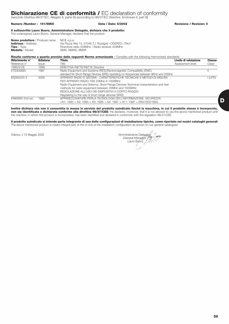
Dichiarazione CE di conformità / EC declaration of conformity(secondo Direttiva 98/37/EC, Allegato II, parte B) (according to 98/37/EC Directive, Enclosure II, part B)
Numero /Number : 151/SMXI Data / Date: 5/2002 Revisione / Revision: 0
Il sottoscritto Lauro Buoro, Amministratore Delegato, dichiara che il prodotto:The undersigned Lauro Buoro, General Manager, declares that the product:
Nome produttore / Producer name: NICE s.p.a.Indirizzo / Address: Via Pezza Alta 13, 31046 Z.I. Rustignè –ODERZO- ITALYTipo / Type: Ricevitore radio 433MHz / Radio receiver 433MHzModello / Model: SMXI, SMXIS, SMXIF
Risulta conforme a quanto previsto dalle seguenti Norme armonizzate / Complies with the following Harmonised standardsRiferimento n° Edizione Titolo Livello di valutazione ClasseReference n° Issue Title Assessment level Class1999/5/CE 1999 DIRETTIVA R&TTE/R&TTE DirectiveETS300683 1997 Radio Equipment and Systems (RES);Electromagnetic Compatibility (EMC) II
standard for Short Range Devices (SRD) operating on frequencies between 9KHz and 25GHzEN300220-3 2000 APPARATI RADIO E SISTEMI - CARATTERISTICHE TECNICHE E METODI DI MISURA I (LPD)
PER APPARATI RADIO TRA 25MHz A 1000MHzRadio Equipment and Sistems- Short Range Devices-Technical characteristics and test methods for radio equipment between 25MHz and 1000MHzREGOLAZIONE ALL’USO DEI DISPOSITIVI A CORTO RAGGIORegolating to the use of short range devices (SRD)
EN60950 2nd ed. 1992 APPARECCHIATURE PERLA TECNOLOGIA DELL’INFORMAZIONE. SICUREZZA. +A1: 1993 + A2: 1993 + A3: 1995 + A4: 1997 + A11: 1997 + EN41003/1993.
Inoltre dichiara che non è consentita la messa in servizio del prodotto suindicato finché la macchina, in cui il prodotto stesso è incorporato,non sia identificata e dichiarata conforme alla direttiva 98/37/CEE/ He declares, moreover, that it is not allowed to use the above mentioned product untilthe machine, in which this product is incorporated, has been identified and declared in conformity with the regulation 98/37/CEE.
Il prodotto suindicato si intende parte integrante di una delle configurazioni di installazione tipiche, come riportato nei nostri cataloghi generaliThe above mentioned product is meant integral part of the of one of the installation configuration as shown on our general catalogues
Oderzo, li 13 Maggio 2002 (Amministratore Delegato)(General Manager)
Lauro Buoro
D
59
60
central de mandomotorreductoresrobo, thor
Advertencias:
Este manual está destinado sólo al personal técnicocualificado para la instalación. Ninguna información contenidaen este manual puede ser considerada de interés para elusuario final. La central está destinada al accionemiento de actuadoreselectromecánicos para la automatización de cancelas opuertas de hojas de batiente. Cualquier otro uso se consideraimpropio y, por lo tanto, está prohibido por las normas vigentes.Se aconseja leer con atención, una vez como mínimo, todas lasinstrucciones antes de proceder con la instalación.
!
Índice: pág.
1 Descripción del producto 61
2 Instalación 612.1 Instalación típica 612.2 Conexiones eléctricas 622.2.1 Esquema eléctrico 622.2.2 Descripción de las conexiones 622.2.3 Fototest 632.2.4 Control de las conexiones 64
3 Regulaciones 64
4 Ensayo 65
5 Modos de funcionamiento 66
pág.
6 Funciones programables 666.1 Descripción de las funciones 67
7 Cómo hacer para... 68
8 Accesorios Opcionales 69
9 Mantenimiento 69
10 Desguace 69
11 Qué hay que hacer si… 69
12 Características técnicas 69
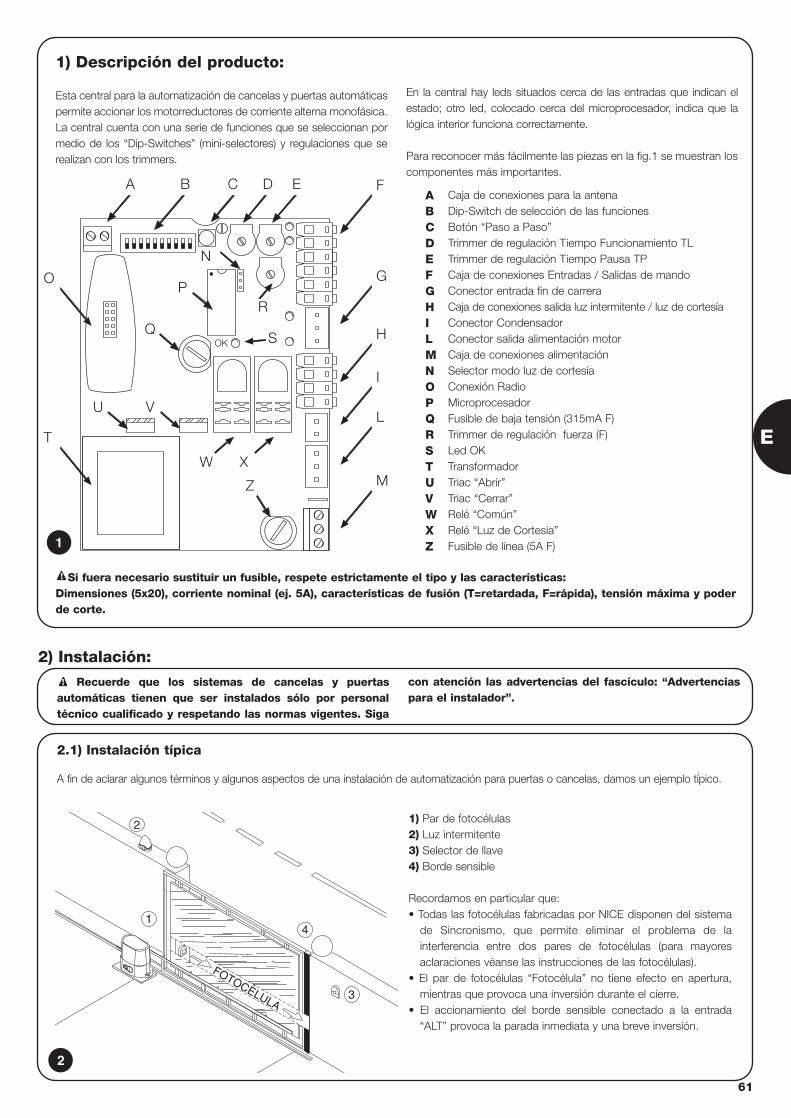
E
61
1) Descripción del producto:
Esta central para la automatización de cancelas y puertas automáticaspermite accionar los motorreductores de corriente alterna monofásica.La central cuenta con una serie de funciones que se seleccionan pormedio de los “Dip-Switches” (mini-selectores) y regulaciones que serealizan con los trimmers.
En la central hay leds situados cerca de las entradas que indican elestado; otro led, colocado cerca del microprocesador, indica que lalógica interior funciona correctamente.
Para reconocer más fácilmente las piezas en la fig.1 se muestran loscomponentes más importantes.
OK
BA C
R
D E F
G
H
I
L
M
P
S
Z
O
T
U V
Q
N
W X
Caja de conexiones para la antenaDip-Switch de selección de las funcionesBotón “Paso a Paso”Trimmer de regulación Tiempo Funcionamiento TLTrimmer de regulación Tiempo Pausa TPCaja de conexiones Entradas / Salidas de mandoConector entrada fin de carreraCaja de conexiones salida luz intermitente / luz de cortesíaConector CondensadorConector salida alimentación motorCaja de conexiones alimentaciónSelector modo luz de cortesíaConexión RadioMicroprocesadorFusible de baja tensión (315mA F)Trimmer de regulación fuerza (F)Led OKTransformadorTriac “Abrir”Triac “Cerrar”Relé “Común”Relé “Luz de Cortesía”Fusible de línea (5A F)
ABCDEFGHILMNOPQRSTUVWXZ1
2.1) Instalación típica
A fin de aclarar algunos términos y algunos aspectos de una instalación de automatización para puertas o cancelas, damos un ejemplo típico.
Recuerde que los sistemas de cancelas y puertasautomáticas tienen que ser instalados sólo por personaltécnico cualificado y respetando las normas vigentes. Siga
con atención las advertencias del fascículo: “Advertenciaspara el instalador”.
!
2) Instalación:
2
4
3
FOTOCÈLULA
2
1
1) Par de fotocélulas2) Luz intermitente3) Selector de llave4) Borde sensible
Recordamos en particular que:• Todas las fotocélulas fabricadas por NICE disponen del sistema
de Sincronismo, que permite eliminar el problema de lainterferencia entre dos pares de fotocélulas (para mayoresaclaraciones véanse las instrucciones de las fotocélulas).
• El par de fotocélulas “Fotocélula” no tiene efecto en apertura,mientras que provoca una inversión durante el cierre.
• El accionamiento del borde sensible conectado a la entrada“ALT” provoca la parada inmediata y una breve inversión.
Si fuera necesario sustituir un fusible, respete estrictamente el tipo y las características: Dimensiones (5x20), corriente nominal (ej. 5A), características de fusión (T=retardada, F=rápida), tensión máxima y poderde corte.
!
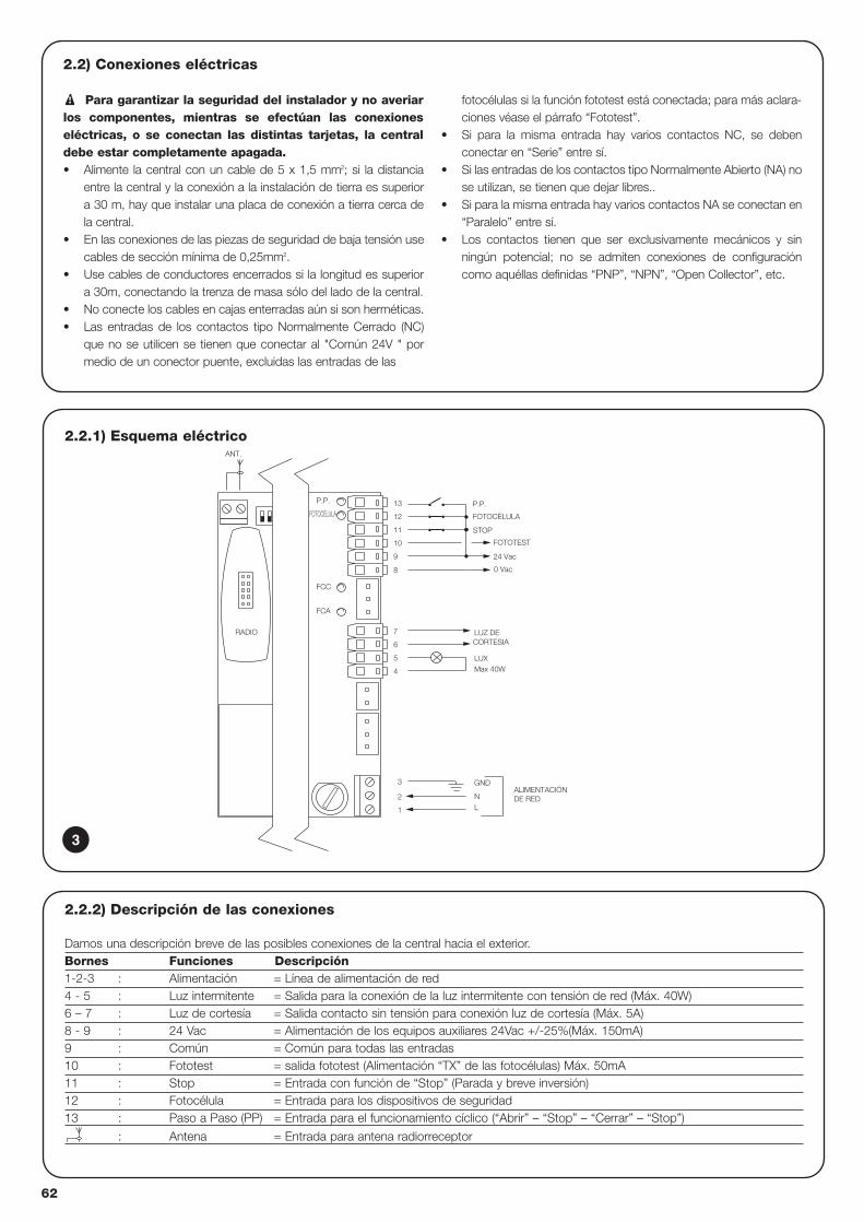
62
2.2.1) Esquema eléctrico
ALIMENTACIÓN DE RED
P.P.
FOTOCÈLULA
FCA
FCC
FOTOTEST
24 Vac
0 Vac
8
GND
LUXMax 40W
ANT.
FOTOCÈLULA
P.P.
STOP11
10
9
12
13
CORTESIALUZ DE
4
5
6
L
3
1
2
7
N
RADIO
2.2) Conexiones eléctricas
Para garantizar la seguridad del instalador y no averiarlos componentes, mientras se efectúan las conexioneseléctricas, o se conectan las distintas tarjetas, la centraldebe estar completamente apagada.• Alimente la central con un cable de 5 x 1,5 mm2; si la distancia
entre la central y la conexión a la instalación de tierra es superiora 30 m, hay que instalar una placa de conexión a tierra cerca dela central.
• En las conexiones de las piezas de seguridad de baja tensión usecables de sección mínima de 0,25mm2.
• Use cables de conductores encerrados si la longitud es superiora 30m, conectando la trenza de masa sólo del lado de la central.
• No conecte los cables en cajas enterradas aún si son herméticas. • Las entradas de los contactos tipo Normalmente Cerrado (NC)
que no se utilicen se tienen que conectar al "Común 24V " pormedio de un conector puente, excluidas las entradas de las
fotocélulas si la función fototest está conectada; para más aclara-ciones véase el párrafo “Fototest”.
• Si para la misma entrada hay varios contactos NC, se debenconectar en “Serie” entre sí.
• Si las entradas de los contactos tipo Normalmente Abierto (NA) nose utilizan, se tienen que dejar libres..
• Si para la misma entrada hay varios contactos NA se conectan en“Paralelo” entre sí.
• Los contactos tienen que ser exclusivamente mecánicos y sinningún potencial; no se admiten conexiones de configuracióncomo aquéllas definidas “PNP”, “NPN”, “Open Collector”, etc.
!
2.2.2) Descripción de las conexiones
Damos una descripción breve de las posibles conexiones de la central hacia el exterior.Bornes Funciones Descripción1-2-3 : Alimentación = Línea de alimentación de red4 - 5 : Luz intermitente = Salida para la conexión de la luz intermitente con tensión de red (Máx. 40W)6 – 7 : Luz de cortesía = Salida contacto sin tensión para conexión luz de cortesía (Máx. 5A)8 - 9 : 24 Vac = Alimentación de los equipos auxiliares 24Vac +/-25%(Máx. 150mA) 9 : Común = Común para todas las entradas10 : Fototest = salida fototest (Alimentación “TX” de las fotocélulas) Máx. 50mA11 : Stop = Entrada con función de “Stop” (Parada y breve inversión)12 : Fotocélula = Entrada para los dispositivos de seguridad13 : Paso a Paso (PP) = Entrada para el funcionamiento cíclico (“Abrir” – “Stop” – “Cerrar” – “Stop”)
: Antena = Entrada para antena radiorreceptor
3
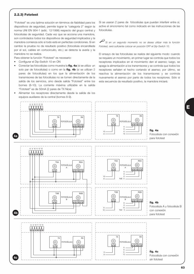
E
63
2.2.3) Fototest
“Fototest” es una óptima solución en términos de fiabilidad para losdispositivos de seguridad, permite lograr la “categoría 2” según lanorma UNI EN 954-1 (edic. 12/1998) respecto del grupo central yfotocélulas de seguridad. Cada vez que se acciona una maniobra,son controlados todos los dispositivos de seguridad implicados y lamaniobra comienza sólo si todo está en perfectas condiciones. Si encambio la prueba no da resultado positivo (fotocélula encandiladapor el sol, cables en cortocircuito, etc.) se detecta la avería y lamaniobra no se realiza.Para obtener la función “Fototest” es necesario:• Configurar el Dip-Switch 10 en ON • Conectar las fotocélulas como muestra la fig. 4a (si se utiliza un
solo par de fotocélulas) o como en la fig. 4b (si se utilizan 2pares de fotocélulas) en los que la alimentación de lostransmisores de las fotocélulas no se tomen directamente de lasalida de los servicios, sino desde salida “Fototest” entre losbornes (8-10). La corriente máxima utilizable en la salida“Fototest” es de 50mA (2 pares de TX Nice)
• Alimentar los receptores directamente desde la salida de losequipos auxiliares de la central (bornes 8-9).
Si se usaran 2 pares de fotocélulas que puedan interferir entre sí,active el sincronismo tal como indicado en las instrucciones de lasfotocélulas.
Si en un segundo momento no se desea utilizar más la función
Fototest, será suficiente colocar en posición OFF el Dip-Switch 10.
El ensayo de las fotocélulas se realiza del siguiente modo: cuandose requiere un movimiento, en primer lugar se controla que todos losreceptores implicados en el movimiento den el asenso; luego, seapaga la alimentación a los transmisores y se controla que todos losreceptores señalen el hecho cortando el asenso; por último, sereactiva la alimentación de los transmisores y se controlanuevamente el asenso por parte de todos los receptores. Sólo siesta secuencia da resultado positivo, la maniobra iniciará.
3 4 5
RX
1 2
9
98
TX
21
98 12
RX
4 5321
TX
21
1311 1298 10
FOTOCÈLULA FOTOCÈLULA
RxA
RxB
5421 3
1298
5
RXBTXB
21
810
RXB
4 5321
TXB
21
5421 3
98
59
RXATXA
21
810
4 5
RXA
1311 12
2 31
TXA
1 2
98 10
FOTOCÈLULAA
FOTOCÈLULAA
FOTOCÈLULAB
FOTOCÈLULAB
12 13111098
RX
3 4 51 2
9
912
8
1 2
108
RX
3 4 51 2
TX
1 2
FOTOCÈLULA FOTOCÈLULA
TX
4a
4b
4c
fig. 4aFotocélula con conexión para fototest
fig. 4bFotocélula A y fotocélula Bcon conexión para fototest
fig. 4cFotocélula con conexión sin fototest
64
2.2.4) Control de las conexiones
Las siguientes operaciones se efectúan con los circuitos bajotensión; la mayoría de los circuitos es a muy baja tensión deseguridad y, por ello, no son peligrosos; algunas piezas están bajotensión de red, es decir, “¡MUY PELIGROSAS”!Tenga mucho cuidado en lo que está haciendo y NUNCATRABAJE SOLO!
• Alimente la central y controle de inmediato que entre los bornes 8-9haya una tensión de 24Vca.
• Controle que, después de un parpadeo rápido, el led “OK” parpadeecon una cadencia regular.
• Entonces, controle que los leds que corresponden a las entradas concontactos tipo NC estén encendidos (todos los dispositivos deseguridad accionados) y que los leds que corresponden a lasentradas con contactos tipo NA estén apagados (ningúnaccionamiento activo); si esto no se produce, controle las conexionesy que todos los dispositivos funcionen correctamente. La entradaSTOP se acciona apagando FCA y FCC.
• Controle que los fines de carrera estén bien conectados; mueva lapalanca del fin de carrera y controle que el fin de carreracorrespondiente se accione, apagando el led respectivo en la central.
• Desbloquee la hoja y colóquela en la mitad de la carrera, luegobloquéela para que se pueda abrir o cerrar libremente.
• Entonces, controle si el movimiento se efectúa en la direccióncorrecta, es decir, controle que el movimiento previsto por la central y aquél efectivo de las hojas correspondan. Ese control esfundamental; si la dirección es incorrecta, en algunos casos (porejemplo en modo “semiautomático”) la automatización
aparentemente podría funcionar regularmente; en efecto, el ciclo“Abrir” es parecido al ciclo “Cerrar” con la diferencia fundamental deque los dispositivos de seguridad son ignorados en la maniobra decierre, la cual es generalmente más peligrosa, y se accionan durantela apertura provocando el cierre sobre el obstáculo con resultadosdesastrosos.
• Para controlar si el sentido de rotación es correcto, es suficiente darun breve impulso en la entrada Paso a Paso (PP); la primera maniobraque la central efectúa tras haber sido accionada siempre es Abrir,luego es suficiente controlar si la automatización se abre; por último,si el movimiento se ha efectuado en el sentido incorrecto esnecesario:
� Apagar la alimentación� Girar 180° el conector de alimentación del motor y el de los fines de carrera. (Ref. “L” y Ref. “G” de fig.1)� Una vez efectuado lo anterior, conviene probar nuevamente
si el sentido de rotación es correcto, repitiendo el último punto.
El led “OK”, situado en el centro de la tarjeta, tiene la función de señalar
el estado de la lógica interior: un parpadeo regular cada 1 segundo indica que el
microprocesador interior está activo y espera el mando. En cambio, cuando el
microprocesador reconoce una variación del estado de una entrada (bien de una
entrada de mando o de un Dip-Switch de las funciones) produce un parpadeo
doble rápido, incluso si la variación no provoca efectos inmediatos. Un parpadeo
rápido de 3 s. indica que la central se ha apenas encendido y está realizando un
ensayo de las piezas internas; por último un parpadeo inconstante indica que el
ensayo no tuvo resultados positivos y, por consiguiente, hay una avería.
!
Las regulaciones se efectúan con los trimmers que actúanmodificando los siguientes parámetros:
Tiempo Funcionamiento (TL): Regula la duración máxima de la maniobra de apertura o cierre.
Para regular el tiempo de funcionamiento TL, seleccione el modo defuncionamiento “Semiautomático” desplazando hacia ON el Dip-Switch 1 y luego regule el Trimmer TL a la mitad de la carrera. Condichas regulaciones realice un ciclo de apertura y de cierre; si fueranecesario, actúe sobre la regulación del Trimmer TL de manera quesea suficiente para cumplir toda la maniobra y que todavía quede unmargen de 2 ó 3s.Si al colocar el Trimmer TL al máximo no se obtiene un tiemposuficiente, corte el conector puente TLM, colocado en el circuitoimpreso cerca del Trimmer TL, para obtener un tiempo deFuncionamiento Mayor (TLM).Si usted quisiera utilizar la función de deceleración, tendrá queregular el Trimmer de manera que la etapa de deceleracióncomience 50 - 70cm antes del accionamiento del fin de carrera.La modificación del Tiempo de funcionamiento tendrá efecto a partirde la próxima maniobra de apertura.
Tiempo Pausa (TP):En el funcionamiento “Automático” regula el tiempo entre el final dela maniobra de apertura y el comienzo de la maniobra de cierre.
Para regular el Tiempo Pausa TP, seleccione el modo defuncionamiento “Automático” desplazando hacia ON el Dip-Switch
2, luego regule el trimmer TP a placer. Para el control, ejecute unamaniobra de apertura y controle el tiempo que transcurre antes delcierre “Automático”.
Fuerza (F):
Preste mucha atención cuando regule el trimmer “Fuerza” (F),puesto que puede influir sobre el grado de seguridad de laautomatización. Para la regulación hay que actuar por tentativassucesivas, midiendo la fuerza aplicada a la hoja y comparándola concuanto previsto por las normas.
3) Regulaciones:
F
TL TP
TLM
E
65
Concluidos los controles y regulaciones es posible efectuar el ensayo de la instalación.
El ensayo de la automatización tiene que ser efectuado por personal cualificado y experto que deberá establecerlos ensayos previstos de acuerdo con el riesgo presente.
El ensayo es la parte más importante de toda la etapa de realización de la automatización. Cada componente, por ejemplo motor,dispositivo de parada de emergencia, fotocélulas, etc. puede requerir un ensayo específico; por consiguiente, se aconseja seguir losprocedimientos indicados en los manuales de instrucciones respectivos.
Para el ensayo de la central lleve a cabo el siguiente procedimiento:
1. Seleccione las funciones: • Configure en ON el Dip-Switch 1 (Funcionamiento “Semiautomático”)• Configure en OFF todos los demás Dip-Switches
2. Oprima el botón de mando “Paso a Paso” y compruebe que:• Empiece una maniobra de apertura• Se active la luz intermitente• El movimiento se detenga al alcanzar el fin de carrera de apertura FCA.
3. Oprima de nuevo el botón de mando “Paso a Paso” y compruebe que:• Empiece una maniobra de cierre• Se active la luz intermitente• El movimiento se detenga al alcanzar el fin de carrera de cierre FCC
4. Haga iniciar una maniobra de apertura y controle que durante la maniobra, el accionamiento de un dispositivo:• Conectado a la entrada “Stop”, provoque la parada inmediata de un movimiento y una breve inversión• Conectado a la entrada “Fotocélula”, no tenga ningún efecto
5. Haga iniciar una maniobra de cierre y controle que durante la maniobra, el accionamiento de un dispositivo:• Conectado a la entrada “Stop”, provoque la parada inmediata de un movimiento y una breve inversión• Conectado a la entrada “Fotocélula”, provoque la parada y la inversión de la maniobra
6. Oprima el botón “Paso a Paso” y controle que la activación de la entrada provoque un paso en la secuencia:• “Abrir” – “Stop” – “Cerrar” – “Stop”
7. Si se utiliza la función fototest, controle la eficiencia del ensayo:• Cubra la fotocélula "Fotocélula", haga iniciar una maniobra y controle que dicha maniobra no arranque• Realice un cortocircuito en el contacto de la fotocélula "Fotocélula", haga iniciar una maniobra y controle que dicha maniobra no arranque.
8. Realice los ensayos para medir las “Fuerzas de Impacto”, como previsto por la norma EN 12445.
Si al final del ensayo se activan otras funciones que puedan reducir la seguridad de la instalación, es necesario efectuar el ensayo específicode dichas funciones.
!
4) Ensayo
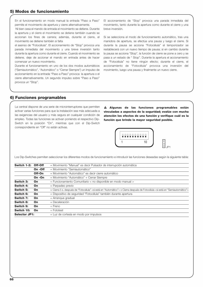
66
5) Modos de funcionamiento
En el funcionamiento en modo manual la entrada “Paso a Paso”permite el movimiento de apertura y cierre alternativamente.Ni bien cesa el mando de entrada el movimiento se detiene. Durantela apertura y el cierre el movimiento se detiene también cuando seaccionan los fines de carrera; además, durante el cierre, elmovimiento se detiene también si faltael asenso de “Fotocélula”. El accionamiento de “Stop” provoca unaparada inmediata del movimiento y una breve inversión tantodurante la apertura como durante el cierre. Cuando el movimiento sedetiene, deje de accionar el mando en entrada antes de hacercomenzar un nuevo movimiento.Durante el funcionamiento en uno de los dos modos automáticos(“Semiautomático”, “Automático” o “Cerrar Siempre”) un impulso deaccionamiento en la entrada “Paso a Paso” provoca la apertura o elcierre alternativamente. Un segundo impulso sobre “Paso a Paso”provoca un “Stop”.
El accionamiento de “Stop” provoca una parada inmediata delmovimiento, tanto durante la apertura como durante el cierre y unabreve inversión.
Si se selecciona el modo de funcionamiento automático, tras unamaniobra de apertura, se efectúa una pausa y luego el cierre. Sidurante la pausa se acciona “Fotocélula” el temporizador serestablecerá con un nuevo tiempo de pausa; si en cambio durantela pausa se acciona “Stop”, la función de cierre se pone a cero y sepasa a un estado de “ Stop”. Durante la apertura el accionamientode “Fotocélula” no tiene ningún efecto; durante el cierre, elaccionamiento de “Fotocélula” provoca una inversión delmovimiento, luego una pausa y finalmente un nuevo cierre.
La central dispone de una serie de microinterruptores que permitenactivar varias funciones para que la instalación sea más adecuada alas exigencias del usuario y más segura en cualquier condición deempleo. Todas las funciones se activan poniendo el respectivo Dip-Switch en la posición “On”, mientras que con el Dip-Switchcorrespondiente en “Off” no están activas.
Algunas de las funciones programables estánvinculadas a aspectos de la seguridad; evalúe con muchaatención los efectos de una función y verifique cuál es lafunción que brinde la mayor seguridad posible.
!
Los Dip-Switches permiten seleccionar los diferentes modos de funcionamiento e introducir las funciones deseadas según la siguiente tabla:
Switch 1-2: Off-Off = Movimiento “Manual” es decir Pulsador de interrupción automáticaOn -Off = Movimiento “Semiautomático”Off-On = Movimiento “Automático” es decir cierre automáticoOn -On = Movimiento “Automático” + Cerrar Siempre
Switch 3: On = Funcionamiento Comunitario < no disponible en modo manual >Switch 4: On = Parpadeo previoSwitch 5: On = Cierra 5 s. después de “Fotocélula” <si está en “Automático”> o Cierra después de Fotocélula <si está en “Semiautomático”>
Switch 6: On = Dispositivo de seguridad “Fotocélula” también durante aperturaSwitch 7: On = Arranque gradualSwitch 8: On = DeceleraciónSwitch 9: On = FrenoSwitch 10: On = FototestSelector JP1: = Luz de cortesía en modo por impulsos
6) Funciones programables
101
JP1
E
67
6.1) Descripción de las funciones
A continuación, damos una breve descripción de las funciones que se pueden configurar colocando en “On” el Dip-Switch correspondiente.
Switch 1-2: Off-Off = Movimiento “Manual” (Pulsador de interrupción automática)On-Off = Movimiento “Semiautomático”Off-On = Movimiento “Automático” (cierre automático)On-On = Movimiento “Automático” + “Cerrar Siempre”
Durante el funcionamiento “Manual” el movimiento se efectúa sólo hasta que se acciona el mando (botón apretado).En modo “Semiautomático” es suficiente dar un impulso de mando para que se cumpla todo el movimiento, hasta que termine el TiempoFuncionamiento o hasta alcanzar el fin de carrera. En el funcionamiento en modo “Automático”, después de la apertura, se efectúa unapausa y luego un cierre automático. La función “Cerrar Siempre” se acciona tras un corte de alimentación, si detecta que la cancela está abierta, se pone en marchaautomáticamente una maniobra de cierre, antecedida por 5 segundos de parpadeo previo.
Switch 3: On = Funcionamiento Comunitario (no disponible en modo manual)Durante el funcionamiento comunitario, una vez que se puso en marcha un movimiento de apertura, la maniobra no puede ser interrumpidapor otros impulsos de mando en “Paso a Paso”, hasta que no finalice el movimiento de apertura. Durante el movimiento de cierre, al efectuar un nuevo accionamiento, se produce la parada y la inversión del movimiento y se abrenuevamente.
Switch 4: On = Parpadeo previoAl recibir el impulso de mando, primero se activa la luz intermitente, luego, transcurridos 5 s. (2 s. si está en modo “manual”) comienza elmovimiento
Switch 5: On = Cierra 5 s. después de Fotocélula <si está en “Automático”> o Cierra después de Fotocélula <si está en “Semiautomático”>Esta función, si está en ciclo automático, permite mantener la cancela abierta sólo por el tiempo necesario para el paso; en efecto, despuésde la activación de Fotocélula la maniobra se detiene. Después de 5 s., arrancará automáticamente una maniobra de cierre. Si está en ciclosemiautomático, un accionamiento de fotocélula en la maniobra de cierre activa el cierre automático con el tiempo de pausa regulado.
Switch 6: On = Dispositivo de seguridad “Fotocélula” también durante aperturaNormalmente, el dispositivo de seguridad “Fotocélula” está activo sólo durante la maniobra de cierre, si el Dip-Switch 6 se coloca en "On"el accionamiento del dispositivo de seguridad provoca una interrupción del movimiento también durante la apertura.Si está en “Semiautomático” o “Automático”, el movimiento de apertura se reanudará inmediatamente después de la desconexión.
Switch 7: On = Arranque gradualEjecuta el arranque gradual del movimiento evitando sacudidas indeseables de la automatización.
Switch 8: On = Deceleración La deceleración consiste en una disminución de la velocidad del 30% de la velocidad nominal, para reducir la fuerza de impacto en las zonasde apertura y cierre de la cancela.
Una vez activada la función de deceleración, habrá que regular el Trimmer Tiempo de funcionamiento (TL) puesto que al comienzo de ladeceleración está asociado el tiempo de funcionamiento configurado. Hay que regular el tiempo de funcionamiento para que la deceleracióncomience a alrededor de 50-70cm antes del accionamiento del fin de carrera.
La función de deceleración, además de disminuir la velocidad de la automatización, disminuye un 70% el par del motor.
En automatizaciones que requieren un par elevado, dicha disminución podría provocar la parada inmediata del motor.
Switch 9: On = FrenoAl final del movimiento se ejecuta un procedimiento de frenado en el motor: primero suave y luego más intenso, para detener la cancelarápidamente pero sin sacudidas.
Switch 10: On = Fototes Esta función permite efectuar un control de la eficiencia de las fotocélulas cada vez que comienza una maniobra. Véase el capítulo Fototest
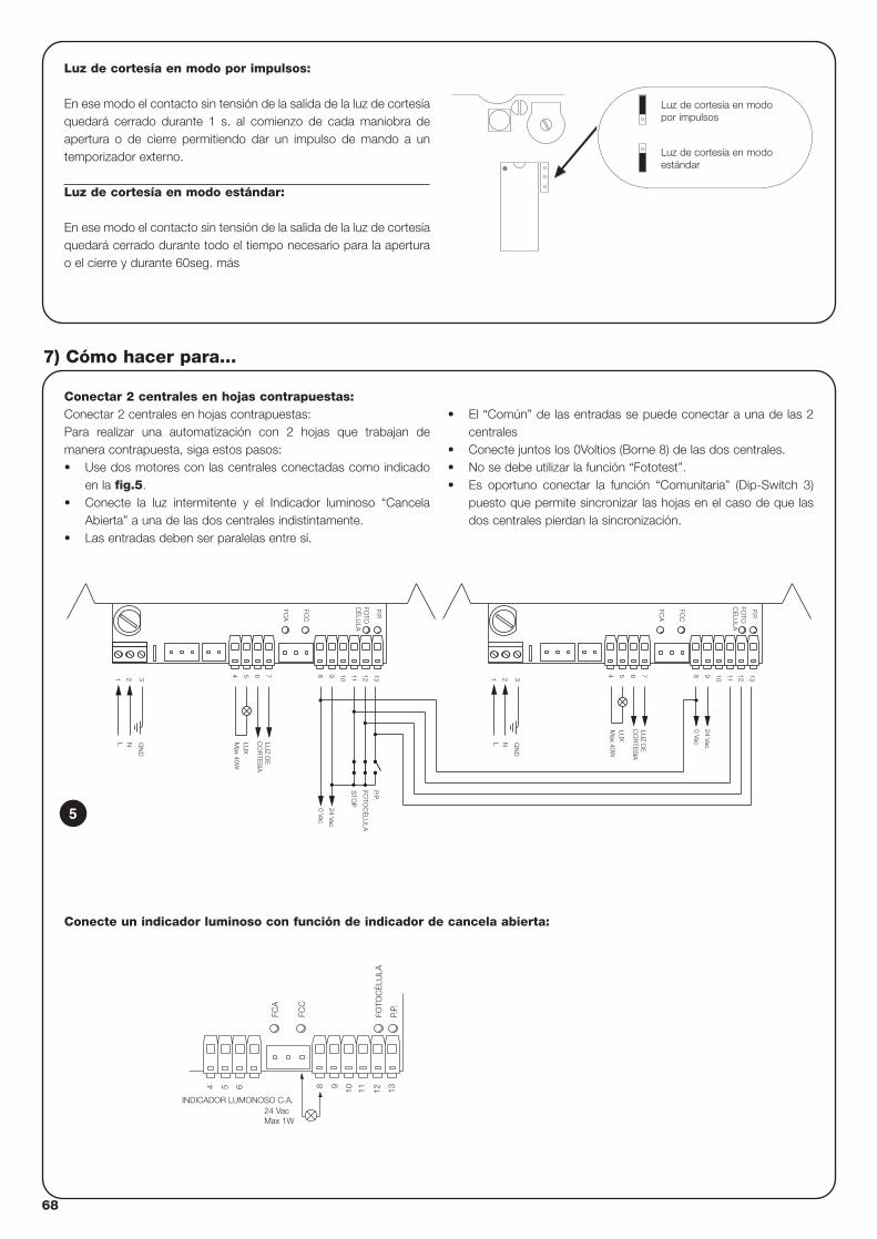
68
Conectar 2 centrales en hojas contrapuestas:Conectar 2 centrales en hojas contrapuestas:Para realizar una automatización con 2 hojas que trabajan demanera contrapuesta, siga estos pasos:• Use dos motores con las centrales conectadas como indicado
en la fig.5.• Conecte la luz intermitente y el Indicador luminoso “Cancela
Abierta” a una de las dos centrales indistintamente.• Las entradas deben ser paralelas entre sí.
• El “Común” de las entradas se puede conectar a una de las 2centrales
• Conecte juntos los 0Voltios (Borne 8) de las dos centrales.• No se debe utilizar la función “Fototest”.• Es oportuno conectar la función “Comunitaria” (Dip-Switch 3)
puesto que permite sincronizar las hojas en el caso de que lasdos centrales pierdan la sincronización.
7) Cómo hacer para...
N
7
21 3
L
654
LUZ D
EC
OR
TES
IA
13129 10 11S
TOP
P.P.
FOTO
CÈ
LULA
FOTO
CÈ
LULA
Max 40W
LUX
GN
D
8
0 Vac
24 Vac
FCC
FCA
FOTO
CÈ
LULA
P.P.
11
0 Vac
24 Vac
CO
RTE
SIA
Max 40W
GN
D3
NL
1 2
LUX
LUZ D
E
54 76 8 9 10
FCA
FCC
12 13P.P.
5
Luz de cortesía en modo por impulsos:
En ese modo el contacto sin tensión de la salida de la luz de cortesíaquedará cerrado durante 1 s. al comienzo de cada maniobra deapertura o de cierre permitiendo dar un impulso de mando a untemporizador externo.
Luz de cortesía en modo estándar:
En ese modo el contacto sin tensión de la salida de la luz de cortesíaquedará cerrado durante todo el tiempo necesario para la aperturao el cierre y durante 60seg. más
Luz de cortesía en modopor impulsos
Luz de cortesía en modoestándar
FCC
FCA
P.P.
54 6 1198 10 12 13
24 VacINDICADOR LUMONOSO C.A.
Max 1W
FOTO
CÈ
LULA
Conecte un indicador luminoso con función de indicador de cancela abierta:
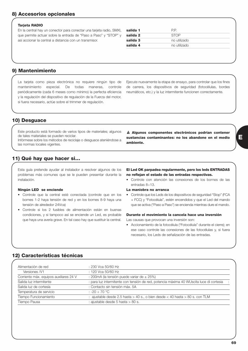
Tarjeta RADIOEn la central hay un conector para conectar una tarjeta radio, SMXI,que permite actuar sobre la entrada de “Paso a Paso” y “STOP” yasí accionar la central a distancia con un transmisor.
salida 1 P.P.salida 2 STOPsalida 3 no utilizadosalida 4 no utilizado
8) Accesorios opcionales
La tarjeta como pieza electrónica no requiere ningún tipo demantenimiento especial. De todas maneras, controleperiódicamente (cada 6 meses como mínimo) la perfecta eficienciay la regulación del dispositivo de regulación de la Fuerza del motor,si fuera necesario, actúe sobre el trimmer de regulación.
Ejecute nuevamente la etapa de ensayo, para controlar que los finesde carrera, los dispositivos de seguridad (fotocélulas, bordesneumáticos, etc.) y la luz intermitente funcionen correctamente.
9) Mantenimiento
Este producto está formado de varios tipos de materiales; algunosde tales materiales se pueden reciclar.Infórmese sobre los métodos de reciclaje o desguace ateniéndose alas normas locales vigentes.
Algunos componentes electrónicos podrían contenersustancias contaminantes: no los abandone en el medioambiente.
!
10) Desguace
Esta guía pretende ayudar al instalador a resolver algunos de losproblemas más comunes que se le pueden presentar durante lainstalación.
Ningún LED se enciende• Controle que la central esté conectada (controle que en los
bornes 1-2 haya tensión de red y en los bornes 8-9 haya unatensión de alrededor 24Vca)
• Controle si los 2 fusibles de alimentación están en buenascondiciones, y si tampoco así se enciende un Led, es probableque haya una avería grave. En tal caso hay que sustituir la central.
El Led OK parpadea regularmente, pero los leds ENTRADASno reflejan el estado de las entradas respectivas.• Controle con atención las conexiones de los bornes de las
entradas 8÷13.La maniobra no arranca• Controle que los Leds de los dispositivos de seguridad “Stop” (FCA
+ FCC) y “Fotocélula”, estén encendidos y que el Led del mandoque se activa (“Paso a Paso”) se encienda mientras dure el mando.
Durante el movimiento la cancela hace una inversión Las causas que provocan una inversión son: • Accionamiento de la fotocélula (“Fotocélula” durante el cierre); en
ese caso controle las conexiones de las fotocélulas y, si fueranecesario, los Leds de señalización de las entradas.
11) Qué hay que hacer si…
Alimentación de red : 230 Vca 50/60 HzVersiones /V1 : 120 Vca 50/60 Hz
Corriente máx. equipos auxiliares 24 V : 200mA (la tensión puede variar de ± 25%)Salida luz intermitente : para luz intermitente con tensión de red, potencia máxima 40 WUscita luce di cortesia :Salida luz de cortesía : Contacto sin tensión máx. 5ATemperatura de servicio : -20 ÷ 70 °CTiempo Funcionamiento : ajustable desde 2.5 hasta > 40 s., o bien desde < 40 hasta > 80 s. con TLMTiempo Pausa : ajustable desde 5 hasta > 80 s.
12) Características técnicas
E
69

70
smxi radiorreceptor
Descripción del producto
La peculiaridad de este tipo de radiorreceptor es que el código dereconocimiento es distinto para cada transmisor (y además cambiacada vez que se lo usa). Es decir que para que el receptor puedareconocer determinado transmisor hay que memorizar los códigosde reconocimiento. Dicha operación se repite para cada transmisorque se quiera usar para accionar la central.
En el receptor se pueden memorizar hasta un máximo de 256
transmisores. No está prevista la cancelación de un solo transmisor, sino la
cancelación total de todos los códigos.
Durante la memorización del código del transmisor es posibleescoger entre estas 2 opciones:
Modo I. Cada botón del transmisor activa la salida correspondienteen el receptor, es decir el botón 1 activa la salida 1, el botón 2 activala salida 2, etc. En tal caso, hay una única etapa de memorizaciónpara cada transmisor, durante dicha etapa no importa qué botón seoprima y se ocupa un solo lugar en la memoria.Modo II. A cada botón del transmisor se puede asociar una salidaparticular del receptor, ejemplo: el botón 1 activa la salida 2, el botón2 activa la salida 1, etc. De esa manera hay que memorizar eltransmisor oprimiendo el botón deseado para cada salida que se hade activar. Obviamente, cada botón puede activar una salida sola,mientras que la misma salida puede ser activada por varios botones.Se ocupa un lugar en la memoria por cada botón.
Instalación de la antena
Para funcionar correctamente el receptor requiere una antena tipoABF o ABFKIT; sin antena el alcance se reduce a pocos metros. Laantena se debe instalar lo más alta posible; en presencia deestructuras metálicas o de cemento armado, instale la antena porencima de tales estructuras. Si el cable suministrado con la antena esmuy corto, use un cable coaxial con impedancia 50 ohm (por ej.:RG58 de baja pérdida). El cable no debe medir más de 10 m delongitud.
Si la antena está instalada donde no hay un buen plano de tierra(estructuras de mampostería) es posible conectar el borne del cablede masa, así obteniendo un alcance mayor. Naturalmente la toma detierra debe estar cerca y ser de buena calidad. Si no fuera posibleinstalar la antena sintonizada ABF o ABFKIT, se pueden obtenerresultados discretos usando como antena el trozo de cableentregado con el receptor, colocándolo extendido.
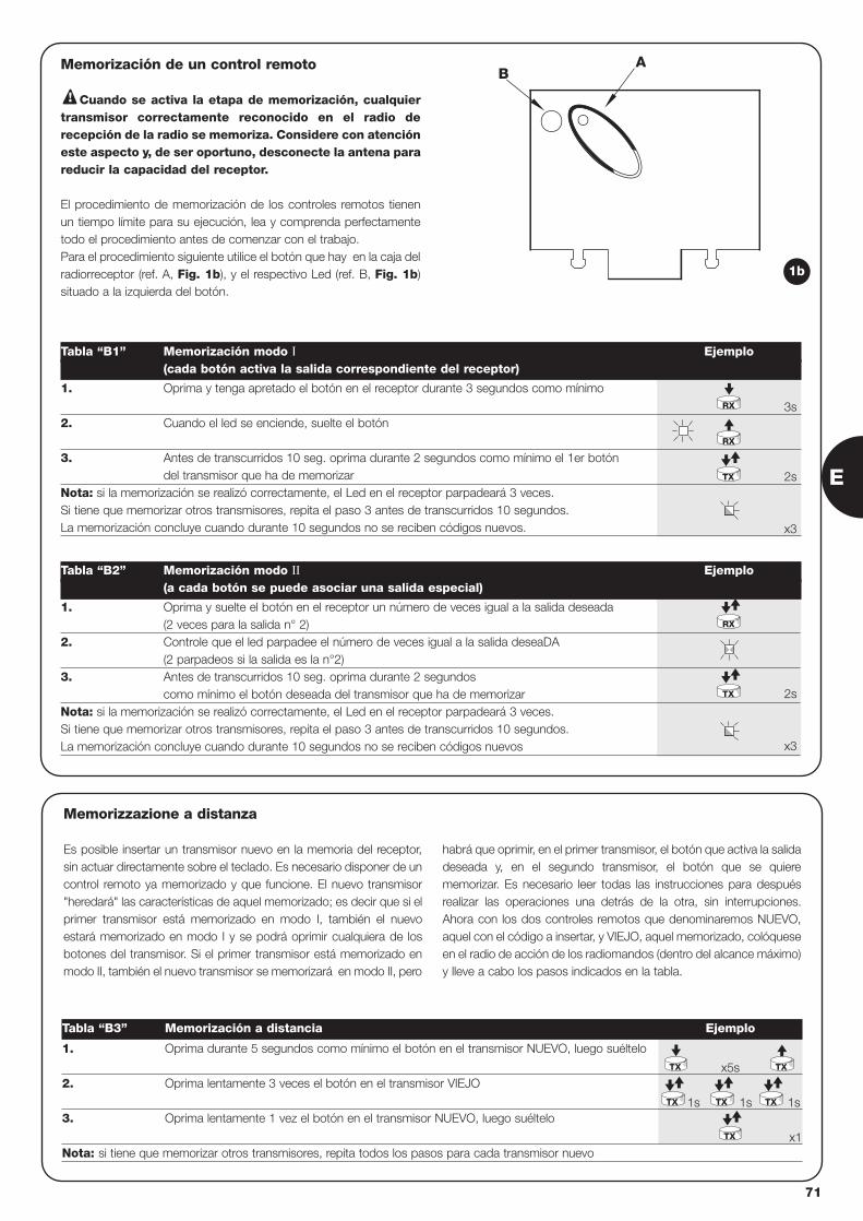
AB
Memorización de un control remoto
Cuando se activa la etapa de memorización, cualquiertransmisor correctamente reconocido en el radio derecepción de la radio se memoriza. Considere con atencióneste aspecto y, de ser oportuno, desconecte la antena parareducir la capacidad del receptor.
El procedimiento de memorización de los controles remotos tienenun tiempo límite para su ejecución, lea y comprenda perfectamentetodo el procedimiento antes de comenzar con el trabajo.Para el procedimiento siguiente utilice el botón que hay en la caja delradiorreceptor (ref. A, Fig. 1b), y el respectivo Led (ref. B, Fig. 1b)situado a la izquierda del botón.
!
3s
2s
x3
2s
x3
1. Oprima y tenga apretado el botón en el receptor durante 3 segundos como mínimo
2. Cuando el led se enciende, suelte el botón
3. Antes de transcurridos 10 seg. oprima durante 2 segundos como mínimo el 1er botóndel transmisor que ha de memorizar
Nota: si la memorización se realizó correctamente, el Led en el receptor parpadeará 3 veces. Si tiene que memorizar otros transmisores, repita el paso 3 antes de transcurridos 10 segundos.La memorización concluye cuando durante 10 segundos no se reciben códigos nuevos.
Tabla “B1” Memorización modo I Ejemplo(cada botón activa la salida correspondiente del receptor)
1. Oprima y suelte el botón en el receptor un número de veces igual a la salida deseada (2 veces para la salida n° 2)
2. Controle que el led parpadee el número de veces igual a la salida deseaDA (2 parpadeos si la salida es la n°2)
3. Antes de transcurridos 10 seg. oprima durante 2 segundos como mínimo el botón deseada del transmisor que ha de memorizar
Nota: si la memorización se realizó correctamente, el Led en el receptor parpadeará 3 veces. Si tiene que memorizar otros transmisores, repita el paso 3 antes de transcurridos 10 segundos.La memorización concluye cuando durante 10 segundos no se reciben códigos nuevos
Tabla “B2” Memorización modo II Ejemplo(a cada botón se puede asociar una salida especial)
RX
RX
TX
TX
RX
1b
x5s
1s 1s 1s
x1
1. Oprima durante 5 segundos como mínimo el botón en el transmisor NUEVO, luego suéltelo
2. Oprima lentamente 3 veces el botón en el transmisor VIEJO
3. Oprima lentamente 1 vez el botón en el transmisor NUEVO, luego suéltelo
Nota: si tiene que memorizar otros transmisores, repita todos los pasos para cada transmisor nuevo
Tabla “B3” Memorización a distancia Ejemplo
TX
TX TX TX
TX
TX
Memorizzazione a distanza
Es posible insertar un transmisor nuevo en la memoria del receptor,sin actuar directamente sobre el teclado. Es necesario disponer de uncontrol remoto ya memorizado y que funcione. El nuevo transmisor"heredará" las características de aquel memorizado; es decir que si elprimer transmisor está memorizado en modo I, también el nuevoestará memorizado en modo I y se podrá oprimir cualquiera de losbotones del transmisor. Si el primer transmisor está memorizado enmodo II, también el nuevo transmisor se memorizará en modo II, pero
habrá que oprimir, en el primer transmisor, el botón que activa la salidadeseada y, en el segundo transmisor, el botón que se quierememorizar. Es necesario leer todas las instrucciones para despuésrealizar las operaciones una detrás de la otra, sin interrupciones.Ahora con los dos controles remotos que denominaremos NUEVO,aquel con el código a insertar, y VIEJO, aquel memorizado, colóqueseen el radio de acción de los radiomandos (dentro del alcance máximo)y lleve a cabo los pasos indicados en la tabla.
E
71
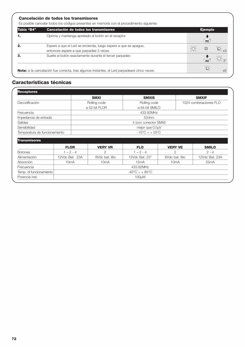
FLOR VERY VR FLO VERY VE SMILOBotones 1 – 2 - 4 2 1 – 2 - 4 2 2 - 4Alimentación 12Vdc Bat. 23A 6Vdc bat. litio 12Vdc Bat. 23° 6Vdc bat. litio 12Vdc Bat. 23AAbsorción 10mA 10mA 15mA 10mA 25mAFrecuencia 433.92MHzTemp. di funcionamiento -40°C ÷ + 85°CPotencia inst. 100µW
Cancelación de todos los transmisores Es posible cancelar todos los códigos presentes en memoria con el procedimiento siguiente:
x3
3°
x5
1. Oprima y mantenga apretado el botón en el receptor
2. Espere a que el Led se encienda, luego espere a que se apague, entonces espere a que parpadee 3 veces
3. Suelte el botón exactamente durante el tercer parpadeo
Nota: si la cancelación fue correcta, tras algunos instantes, el Led parpadeará cinco veces.
Receptores
Transmisores
Tabla “B4” Cancelación de todos los transmisores Ejemplo
RX
RX
SMXI SMXIS SMXIFDecodificación Rolling code Rolling code 1024 combinaciones FLO
a 52 bit FLOR a 64 bit SMILOFrecuencia 433.92MHzImpedancia de entrada 52ohmSalidas 4 (con conector SMXI)Sensibilidad mejor que 0.5µVTemperatura de funcionamiento -10°C ÷ + 55°C
Características técnicas
72
Dichiarazione CE di conformità / EC declaration of conformity(secondo Direttiva 98/37/EC, Allegato II, parte B) (according to 98/37/EC Directive, Enclosure II, part B)
Numero /Number : 151/SMXI Data / Date: 5/2002 Revisione / Revision: 0
Il sottoscritto Lauro Buoro, Amministratore Delegato, dichiara che il prodotto:The undersigned Lauro Buoro, General Manager, declares that the product:
Nome produttore / Producer name: NICE s.p.a.Indirizzo / Address: Via Pezza Alta 13, 31046 Z.I. Rustignè –ODERZO- ITALYTipo / Type: Ricevitore radio 433MHz / Radio receiver 433MHzModello / Model: SMXI, SMXIS, SMXIF
Risulta conforme a quanto previsto dalle seguenti Norme armonizzate / Complies with the following Harmonised standardsRiferimento n° Edizione Titolo Livello di valutazione ClasseReference n° Issue Title Assessment level Class1999/5/CE 1999 DIRETTIVA R&TTE/R&TTE DirectiveETS300683 1997 Radio Equipment and Systems (RES);Electromagnetic Compatibility (EMC) II
standard for Short Range Devices (SRD) operating on frequencies between 9KHz and 25GHzEN300220-3 2000 APPARATI RADIO E SISTEMI - CARATTERISTICHE TECNICHE E METODI DI MISURA I (LPD)
PER APPARATI RADIO TRA 25MHz A 1000MHzRadio Equipment and Sistems- Short Range Devices-Technical characteristics and test methods for radio equipment between 25MHz and 1000MHzREGOLAZIONE ALL’USO DEI DISPOSITIVI A CORTO RAGGIORegolating to the use of short range devices (SRD)
EN60950 2nd ed. 1992 APPARECCHIATURE PERLA TECNOLOGIA DELL’INFORMAZIONE. SICUREZZA. +A1: 1993 + A2: 1993 + A3: 1995 + A4: 1997 + A11: 1997 + EN41003/1993.
Inoltre dichiara che non è consentita la messa in servizio del prodotto suindicato finché la macchina, in cui il prodotto stesso è incorporato,non sia identificata e dichiarata conforme alla direttiva 98/37/CEE/ He declares, moreover, that it is not allowed to use the above mentioned product untilthe machine, in which this product is incorporated, has been identified and declared in conformity with the regulation 98/37/CEE.
Il prodotto suindicato si intende parte integrante di una delle configurazioni di installazione tipiche, come riportato nei nostri cataloghi generaliThe above mentioned product is meant integral part of the of one of the installation configuration as shown on our general catalogues
Oderzo, li 13 Maggio 2002 (Amministratore Delegato)(General Manager)
Lauro Buoro
73
E
74
centrale sterujace silownikirobo, thor
Ostrzeżenie:
Niniejsza instrukcja przeznaczona jest jedynie dla personelutechnicznego z odpowiednimi kwalifikacjami do instalowania.Żadne informacje znajdujące się w niniejszej instrukcji nie sąskierowana do końcowego użytkownika!Instrukcja ta odnosi się tylko do tej centrali i nie może byćzastosowana do innych produktów.Przed przystąpieniem do instalowania zalecamy przeczytać całąinstrukcję!
!
Spis: str.
1 Opis produktu 75
2 Instalowanie 752.1 Zastosowanie typowe 752.2 Połączenia elektryczne 762.2.1 Schemat elektryczne 762.2.2 Opis połączeń 762.2.3 Fototest 772.2.4 Kontrola połączeń 78
3 Regulacje 78
4 Próby ostateczne 79
5 Sposoby funkcjonowania 80
str.
6 Funkcje z możliwością programowania 806.1 Opis funkcji 81
7 Jak postąpić gdy .... 82
8 Akcesoria dodatkowe 83
9 Czynności konserwacyjne 83
10 Utylizacja i recykling 83
11 Co robić gdy... 83
12 Dane techniczne 83
¸
/
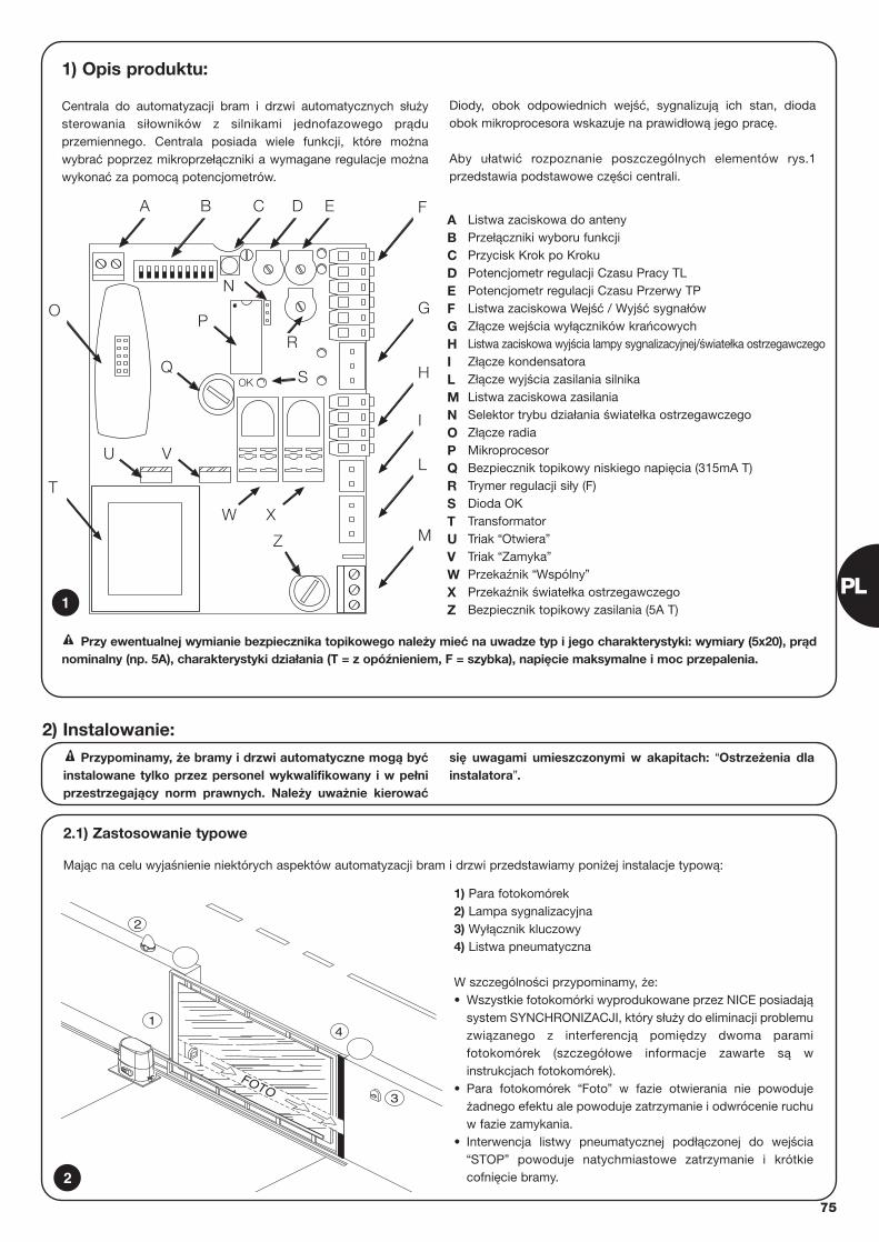
75
1) Opis produktu:
Centrala do automatyzacji bram i drzwi automatycznych służysterowania siłowników z silnikami jednofazowego prąduprzemiennego. Centrala posiada wiele funkcji, które możnawybrać poprzez mikroprzełączniki a wymagane regulacje możnawykonać za pomocą potencjometrów.
Diody, obok odpowiednich wejść, sygnalizują ich stan, diodaobok mikroprocesora wskazuje na prawidłową jego pracę.
Aby ułatwić rozpoznanie poszczególnych elementów rys.1przedstawia podstawowe części centrali.
OK
BA C
R
D E F
G
H
I
L
M
P
S
Z
O
T
U V
Q
N
W X
Listwa zaciskowa do antenyPrzełączniki wyboru funkcjiPrzycisk Krok po KrokuPotencjometr regulacji Czasu Pracy TLPotencjometr regulacji Czasu Przerwy TPListwa zaciskowa Wejść / Wyjść sygnałówZłącze wejścia wyłączników krańcowychListwa zaciskowa wyjścia lampy sygnalizacyjnej/światełka ostrzegawczegoZłącze kondensatoraZłącze wyjścia zasilania silnikaListwa zaciskowa zasilaniaSelektor trybu działania światełka ostrzegawczegoZłącze radiaMikroprocesorBezpiecznik topikowy niskiego napięcia (315mA T)Trymer regulacji siły (F)Dioda OKTransformatorTriak “Otwiera”Triak “Zamyka”Przekaźnik “Wspólny”Przekaźnik światełka ostrzegawczegoBezpiecznik topikowy zasilania (5A T)
ABCDEFGHILMNOPQRSTUVWXZ1
2.1) Zastosowanie typowe
Mając na celu wyjaśnienie niektórych aspektów automatyzacji bram i drzwi przedstawiamy poniżej instalacje typową:
Przypominamy, że bramy i drzwi automatyczne mogą byćinstalowane tylko przez personel wykwalifikowany i w pełniprzestrzegający norm prawnych. Należy uważnie kierować
się uwagami umieszczonymi w akapitach: “Ostrzeżenia dlainstalatora”.
!
2) Instalowanie:
2
4
3
FOTO
2
1
1) Para fotokomórek 2) Lampa sygnalizacyjna3) Wyłącznik kluczowy4) Listwa pneumatyczna
W szczególności przypominamy, że:• Wszystkie fotokomórki wyprodukowane przez NICE posiadają
system SYNCHRONIZACJI, który służy do eliminacji problemuzwiązanego z interferencją pomiędzy dwoma paramifotokomórek (szczegółowe informacje zawarte są winstrukcjach fotokomórek).
• Para fotokomórek “Foto” w fazie otwierania nie powodujeżadnego efektu ale powoduje zatrzymanie i odwrócenie ruchuw fazie zamykania.
• Interwencja listwy pneumatycznej podłączonej do wejścia“STOP” powoduje natychmiastowe zatrzymanie i krótkiecofnięcie bramy.
Przy ewentualnej wymianie bezpiecznika topikowego należy mieć na uwadze typ i jego charakterystyki: wymiary (5x20), prądnominalny (np. 5A), charakterystyki działania (T = z opóźnieniem, F = szybka), napięcie maksymalne i moc przepalenia. !
PL
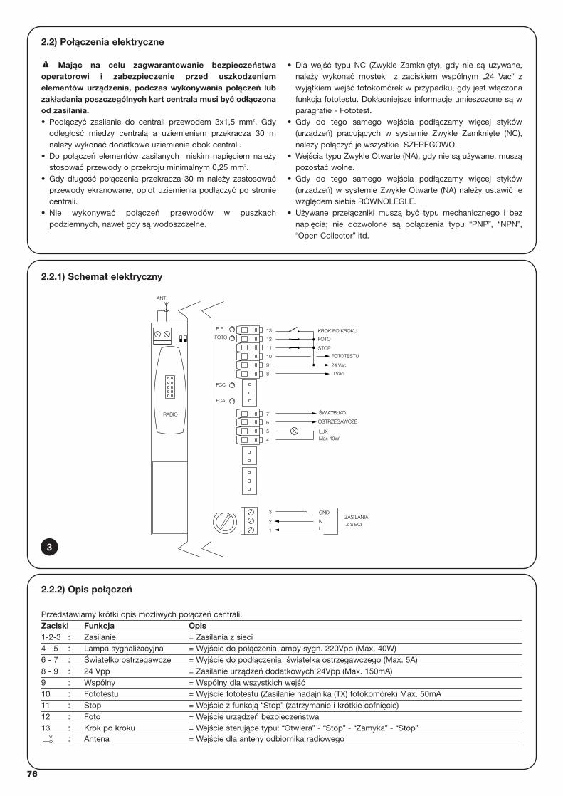
76
2.2.1) Schemat elektryczny
Z SIECI
ZASILANIA
KROK PO KROKU
FOTO
FCA
FCC
FOTOTESTU
24 Vac
0 Vac
8
GND
LUXMax 40W
ANT.
FOTO
P.P.
STOP11
10
9
12
13
OSTRZEGAWCZEOSTRZEGAWCZE
ŚŚWIATEWIATEŁŁKOKO
4
5
6
L
3
1
2
7
N
RADIO
2.2) Połączenia elektryczne
Mając na celu zagwarantowanie bezpieczeństwaoperatorowi i zabezpieczenie przed uszkodzeniemelementów urządzenia, podczas wykonywania połączeń lubzakładania poszczególnych kart centrala musi być odłączonaod zasilania.• Podłączyć zasilanie do centrali przewodem 3x1,5 mm2. Gdy
odległość między centralą a uziemieniem przekracza 30 mnależy wykonać dodatkowe uziemienie obok centrali.
• Do połączeń elementów zasilanych niskim napięciem należystosować przewody o przekroju minimalnym 0,25 mm2.
• Gdy długość połączenia przekracza 30 m należy zastosowaćprzewody ekranowane, oplot uziemienia podłączyć po stroniecentrali.
• Nie wykonywać połączeń przewodów w puszkachpodziemnych, nawet gdy są wodoszczelne.
• Dla wejść typu NC (Zwykle Zamknięty), gdy nie są używane,należy wykonać mostek z zaciskiem wspólnym „24 Vac“ zwyjątkiem wejść fotokomórek w przypadku, gdy jest włączonafunkcja fototestu. Dokładniejsze informacje umieszczone są wparagrafie - Fototest.
• Gdy do tego samego wejścia podłączamy więcej styków(urządzeń) pracujących w systemie Zwykle Zamknięte (NC),należy połączyć je wszystkie SZEREGOWO.
• Wejścia typu Zwykle Otwarte (NA), gdy nie są używane, musząpozostać wolne.
• Gdy do tego samego wejścia podłączamy więcej styków(urządzeń) w systemie Zwykle Otwarte (NA) należy ustawić jewzględem siebie RÓWNOLEGLE.
• Używane przełączniki muszą być typu mechanicznego i beznapięcia; nie dozwolone są połączenia typu “PNP”, “NPN”,“Open Collector” itd.
!
2.2.2) Opis połączeń
Przedstawiamy krótki opis możliwych połączeń centrali.Zaciski Funkcja Opis1-2-3 : Zasilanie = Zasilania z sieci4 - 5 : Lampa sygnalizacyjna = Wyjście do połączenia lampy sygn. 220Vpp (Max. 40W)6 - 7 : Światełko ostrzegawcze = Wyjście do podłączenia światełka ostrzegawczego (Max. 5A)8 - 9 : 24 Vpp = Zasilanie urządzeń dodatkowych 24Vpp (Max. 150mA) 9 : Wspólny = Wspólny dla wszystkich wejść10 : Fototestu = Wyjście fototestu (Zasilanie nadajnika (TX) fotokomórek) Max. 50mA11 : Stop = Wejście z funkcją “Stop” (zatrzymanie i krótkie cofnięcie)12 : Foto = Wejście urządzeń bezpieczeństwa13 : Krok po kroku = Wejście sterujące typu: “Otwiera” - “Stop” - “Zamyka” - “Stop”
: Antena = Wejście dla anteny odbiornika radiowego
3
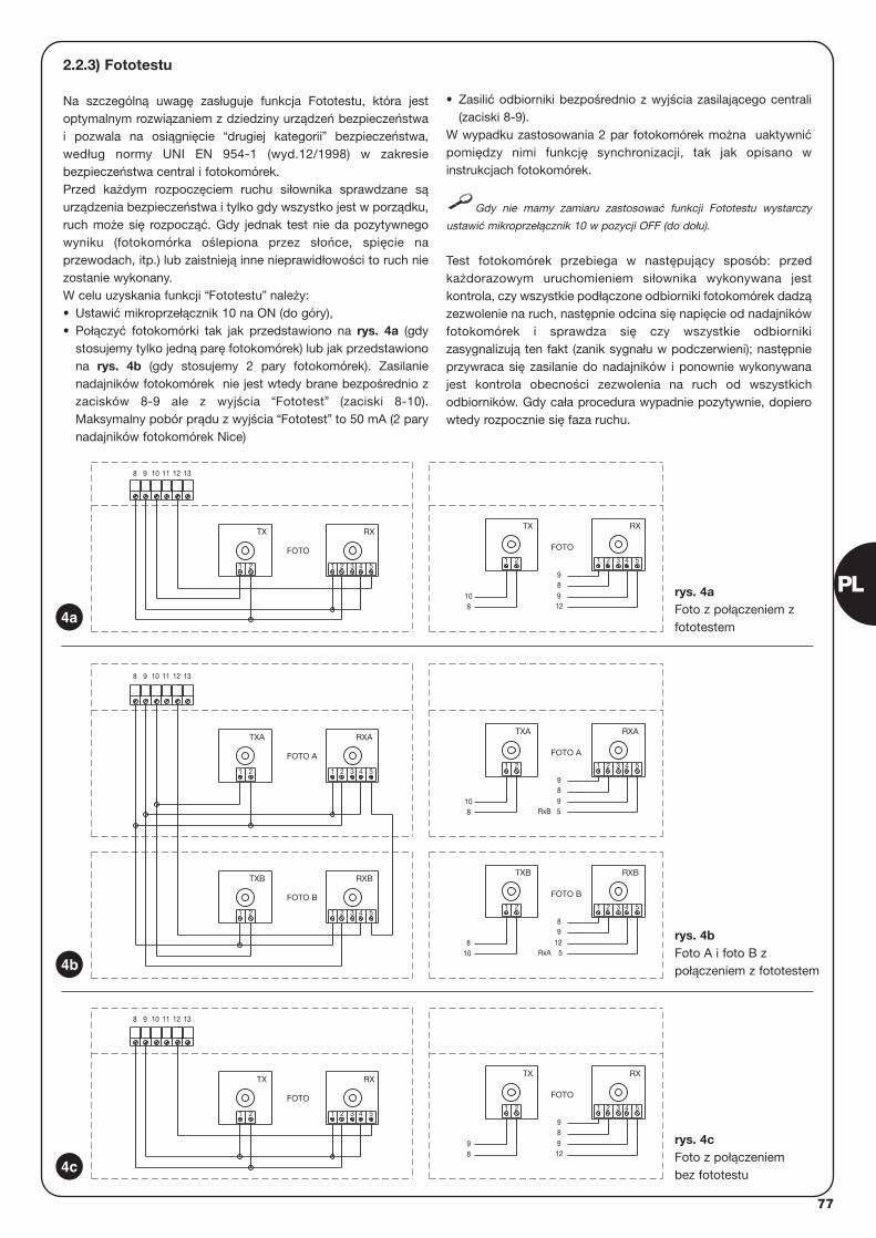
77
2.2.3) Fototestu
Na szczególną uwagę zasługuje funkcja Fototestu, która jestoptymalnym rozwiązaniem z dziedziny urządzeń bezpieczeństwai pozwala na osiągnięcie “drugiej kategorii” bezpieczeństwa,według normy UNI EN 954-1 (wyd.12/1998) w zakresiebezpieczeństwa central i fotokomórek.Przed każdym rozpoczęciem ruchu siłownika sprawdzane sąurządzenia bezpieczeństwa i tylko gdy wszystko jest w porządku,ruch może się rozpocząć. Gdy jednak test nie da pozytywnegowyniku (fotokomórka oślepiona przez słońce, spięcie naprzewodach, itp.) lub zaistnieją inne nieprawidłowości to ruch niezostanie wykonany.W celu uzyskania funkcji “Fototestu” należy: • Ustawić mikroprzełącznik 10 na ON (do góry), • Połączyć fotokomórki tak jak przedstawiono na rys. 4a (gdy
stosujemy tylko jedną parę fotokomórek) lub jak przedstawionona rys. 4b (gdy stosujemy 2 pary fotokomórek). Zasilanienadajników fotokomórek nie jest wtedy brane bezpośrednio zzacisków 8-9 ale z wyjścia “Fototest” (zaciski 8-10).Maksymalny pobór prądu z wyjścia “Fototest” to 50 mA (2 parynadajników fotokomórek Nice)
• Zasilić odbiorniki bezpośrednio z wyjścia zasilającego centrali(zaciski 8-9).
W wypadku zastosowania 2 par fotokomórek można uaktywnićpomiędzy nimi funkcję synchronizacji, tak jak opisano winstrukcjach fotokomórek.
Gdy nie mamy zamiaru zastosować funkcji Fototestu wystarczy
ustawić mikroprzełącznik 10 w pozycji OFF (do dołu).
Test fotokomórek przebiega w następujący sposób: przedkażdorazowym uruchomieniem siłownika wykonywana jestkontrola, czy wszystkie podłączone odbiorniki fotokomórek dadzązezwolenie na ruch, następnie odcina się napięcie od nadajnikówfotokomórek i sprawdza się czy wszystkie odbiornikizasygnalizują ten fakt (zanik sygnału w podczerwieni); następnieprzywraca się zasilanie do nadajników i ponownie wykonywanajest kontrola obecności zezwolenia na ruch od wszystkichodbiorników. Gdy cała procedura wypadnie pozytywnie, dopierowtedy rozpocznie się faza ruchu.
3 4 5
RX
1 2
9
98
TX
21
98 12
RX
4 5
FOTO
321
TX
FOTO
21
1311 1298 10
RxA
RxB
5421 3
1298
FOTO B
5
RXBTXB
21
810
RXB
4 5321
TXB
FOTO B
21
5421 3
98
FOTO A
59
RXATXA
21
810
4 5
RXA
1311 12
2 31
TXA
FOTO A
1 2
98 10
12 13111098
RX
3 4 51 2
9
912
8
FOTO
1 2
108
RX
3 4 51 2
TX
1 2
FOTO
TX
4a
4b
4c
rys. 4aFoto z połączeniem zfototestem
rys. 4b Foto A i foto B zpołączeniem z fototestem
rys. 4cFoto z połączeniembez fototestu
PL
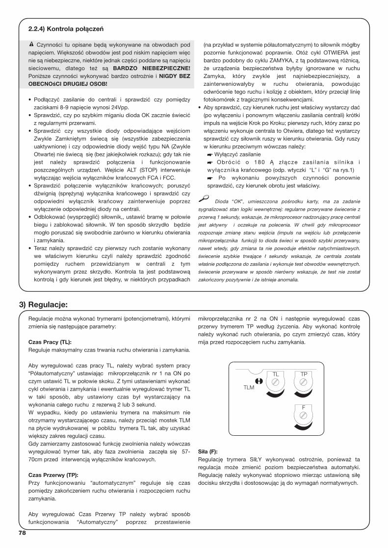
78
Regulacje można wykonać trymerami (potencjometrami), którymizmienia się następujące parametry:
Czas Pracy (TL): Reguluje maksymalny czas trwania ruchu otwierania i zamykania.
Aby wyregulować czas pracy TL, należy wybrać system pracy“Półautomatyczny” ustawiając mikroprzełącznik nr 1 na ON poczym ustawić TL w połowie skoku. Z tymi ustawieniami wykonaćcykl otwierania i zamykania i ewentualnie wyregulować trymer TLw taki sposób, aby ustawiony czas był wystarczający nawykonania całego ruchu z rezerwą 2 lub 3 sekund. W wypadku, kiedy po ustawieniu trymera na maksimum nieotrzymamy wystarczającego czasu, należy przeciąć mostek TLMna płycie wydrukowanej w pobliżu trymera TL tak, aby uzyskaćwiększy zakres regulacji czasu. Gdy zamierzamy zastosować funkcję zwolnienia należy wówczaswyregulować trymer tak, aby faza zwolnienia zaczęła się 57-70cm przed interwencją wyłączników krańcowych.
Czas Przerwy (TP):Przy funkcjonowaniu “automatycznym” reguluje się czaspomiędzy zakończeniem ruchu otwierania i rozpoczęciem ruchuzamykania.
Aby wyregulować Czas Przerwy TP należy wybrać sposóbfunkcjonowania “Automatyczny” poprzez przestawienie
mikroprzełącznika nr 2 na ON i następnie wyregulować czasprzerwy trymerem TP według życzenia. Aby wykonać kontrolęnależy wykonać ruch otwierania, po czym zmierzyć czas, którymija przed rozpoczęciem ruchu zamykania.
Siła (F): Regulację trymera SIŁY wykonywać ostrożnie, ponieważ taregulacja może zmienić poziom bezpieczeństwa automatyki.Regulację należy wykonywać stopniowo mierząc ustawioną siłędocisku skrzydła i dostosowując ją do wymagań normatywnych.
3) Regulacje:
F
TL TP
TLM
2.2.4) Kontrola połączeń
Czynności tu opisane będą wykonywane na obwodach podnapięciem. Większość obwodów jest pod niskim napięciem więcnie są niebezpieczne, niektóre jednak części poddane są napięciusieciowemu, dlatego też są BARDZO NIEBEZPIECZNE!Poniższe czynności wykonywać bardzo ostrożnie i NIGDY BEZOBECNOśCI DRUGIEJ OSOB!
• Podłączyć zasilanie do centrali i sprawdzić czy pomiędzyzaciskami 8-9 napięcie wynosi 24Vpp.
• Sprawdzić, czy po szybkim miganiu dioda OK zacznie świecićz regularnymi przerwami.
• Sprawdzić czy wszystkie diody odpowiadające wejściomZwykle Zamkniętym świecą się (wszystkie zabezpieczeniauaktywnione) i czy odpowiednie diody wejść typu NA (ZwykleOtwarte) nie świecą się (bez jakiejkolwiek rozkazu); gdy tak niejest należy sprawdzić połączenia i funkcjonowanieposzczególnych urządzeń. Wejście ALT (STOP) interweniujewyłączając wejścia wyłączników krańcowych FCA i FCC.
• Sprawdzić połączenie wyłączników krańcowych; poruszyćdźwignią (sprężyną) wyłącznika krańcowego i sprawdzić czyodpowiedni wyłącznik krańcowy zainterweniuje poprzezwyłączenie odpowiedniej diody na centrali.
• Odblokować (wysprzęglić) siłownik,, ustawić bramę w połowiebiegu i zablokować siłownik. W ten sposób skrzydło będziemogło poruszać się swobodnie zarówno w kierunku otwieraniai zamykania.
• Teraz należy sprawdzić czy pierwszy ruch zostanie wykonanywe właściwym kierunku czyli należy sprawdzić zgodnośćpomiędzy ruchem przewidzianym w centrali z tymwykonywanym przez skrzydło. Kontrola ta jest podstawowąkontrolą i gdy kierunek jest błędny, w niektórych przypadkach
(na przykład w systemie półautomatycznym) to siłownik mógłbypozornie funkcjonować poprawnie. Otóż cykl OTWIERA jestbardzo podobny do cyklu ZAMYKA, z tą podstawową różnicą,że urządzenia bezpieczeństwa byłyby ignorowane w ruchuZamyka, który zwykle jest najniebezpieczniejszy, azainterweniowałyby w ruchu otwierania, powodującodwrócenie tego ruchu i kolizję z obiektem, który przeciął linięfotokomórek z tragicznymi konsekwencjami.
• Aby sprawdzić, czy kierunek ruchu jest właściwy wystarczy dać(po wyłączeniu i ponownym włączeniu zasilania centrali) krótkiimpuls na wejście Krok po Kroku; pierwszy ruch, który zaraz powłączeniu wykonuje centrala to Otwiera, dlatego też wystarczysprawdzić czy siłownik ruszy w kierunku otwierania. Gdy ruszyw kierunku przeciwnym wówczas należy:
� Wyłączyć zasilanie� Obrócić o 180 Ą z łącze zas i lan ia s i ln ika iwyłącznika krańcowego (odp. wtyczki “L” i “G” na rys.1)� Po wykonaniu powyższych czynności ponowniesprawdzić, czy kierunek obrotu jest właściwy.
Dioda “OK”, umieszczona pośrodku karty, ma za zadanie
sygnalizować stan logiki wewnętrznej: regularne przerywane świecenie z
przerwą 1 sekundy, wskazuje, że mikroprocesor nadzorujący pracę centrali
jest aktywny i oczekuje na polecenia. W chwili gdy mikroprocesor
rozpoznaje zmianę stanu wejścia (impuls na wejściu lub przełączenie
mikroprzełącznika funkcji) to dioda świeci w sposób szybki przerywany,
nawet wtedy, gdy zmiana ta nie powoduje efektów natychmiastowych.
świecenie szybkie trwające ł sekundy wskazuje, że centrala została
właśnie podłączona do zasilania i wykonuje test obwodów wewnętrznych.
świecenie przerywane w sposób nierówny wskazuje, że test nie został
zakończony pozytywnie i że istnieje anomalia.
!
79
PL
Po zakończeniu kontroli i regulacji można przejść do prób ostatecznych urządzenia.
Próby ostateczne automatyki muszą być wykonane przez doświadczony i wykwalifikowany personel ze względu na to, żeniosą pewne zagrożenia.
Próby są fazą najważniejszą w realizacji automatyki. Każdy pojedynczy element, na przykład silnik, wyłącznik bezpieczeństwa,fotokomórki, itp., mogą wymagać specyficznych testów i dlatego też należy kierować się tutaj procedurami odpowiednich instrukcjiobsługi.
Próby ostateczne centrali należy wykonać według poniższej kolejności:
1. Wybór funkcji: • Ustawić mikroprzełącznik nr 1 na ON (Funkcjonowanie “Półautomatyczne”)• Ustawić wszystkie pozostałe mikroprzełączniki na OFF
2. Przycisnąć przycisk “Krok po Kroku” i sprawdzić czy:• Zacznie się ruch otwierania• Zaświeci się lampa sygnalizacyjna• Ruch zatrzyma się po zadziałaniu wyłącznika krańcowego otwierania FCA
3. Ponownie przycisnąć przycisk “Krok po Kroku” i sprawdzić czy:• Zacznie się ruch zamykania• Zaświeci się lampa sygnalizacyjna• Ruch zatrzyma się po zadziałaniu wyłącznika krańcowego zamykania FCC
4. Rozpocząć ruch otwierania i sprawdzić czy podczas ruchu interwencja urządzenia:• Podłączonego do wejścia “Alt”, powoduje natychmiastowe zatrzymanie ruchu i krótkie jego odwrócenie• Podłączonego do wejścia “Foto”, nie powoduje żadnego efektu
5. Rozpocząć ruch zamykania i sprawdzić czy podczas ruchu interwencja urządzenia:• Podłączonego do wejścia “Alt”, powoduje natychmiastowe zatrzymanie ruchu i krótkie jego odwrócenie• Podłączonego do wejścia “Foto”, spowoduje zatrzymanie i odwrócenie ruchu
6. Przycisnąć kilkakrotnie przycisk “Krok po Kroku” i sprawdzić czy siłownik działa w trybie:• “Otwiera” – “Stop” – “Zamyka” – “Stop”
7. Gdy używa się funkcji fototestu sprawdzić efektywność testu:• “Przeciąć” linię fotokomórek “Foto”, podać sygnał do ruszenia siłownika i sprawdzić czy test zostanie wykonany – brama nie
powinna ruszyć • Zewrzeć wejście “Foto” (12) do wspólnego (9), podać sygnał do ruszenia siłownika i sprawdzić czy zostanie wykonany test –
brama nie powinna ruszyć
8. Wykonać próby rozpoznania przez centralę przeszkody i określić “Siłę Uderzenia” według normy EN 12445.
Gdy po zakończeniu prób odbiorczych zostaną uaktywnione funkcje, które mogą zmniejszyć poziom bezpieczeństwa urządzenia,należy wykonać dla takich funkcji odpowiednie próby.
!
4) Próby ostateczne
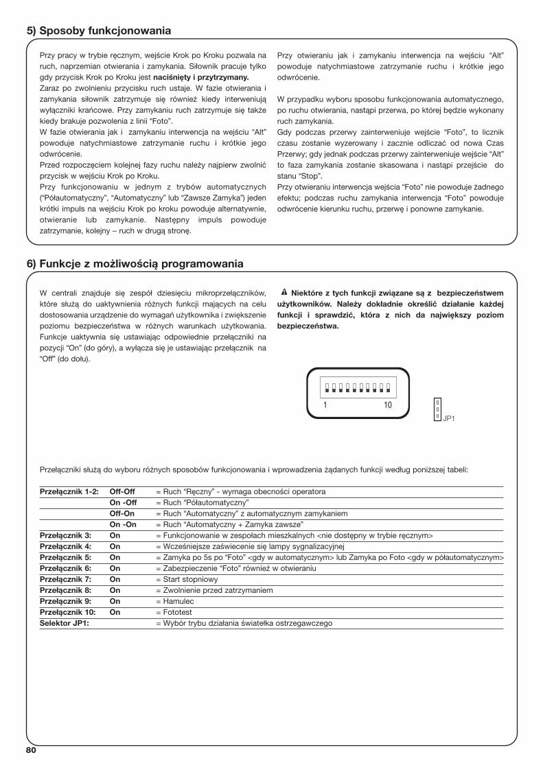
80
5) Sposoby funkcjonowania
Przy pracy w trybie ręcznym, wejście Krok po Kroku pozwala naruch, naprzemian otwierania i zamykania. Siłownik pracuje tylkogdy przycisk Krok po Kroku jest naciśnięty i przytrzymany.Zaraz po zwolnieniu przycisku ruch ustaje. W fazie otwierania izamykania siłownik zatrzymuje się również kiedy interweniująwyłączniki krańcowe. Przy zamykaniu ruch zatrzymuje się takżekiedy brakuje pozwolenia z linii “Foto”.W fazie otwierania jak i zamykaniu interwencja na wejściu “Alt”powoduje natychmiastowe zatrzymanie ruchu i krótkie jegoodwrócenie. Przed rozpoczęciem kolejnej fazy ruchu należy najpierw zwolnićprzycisk w wejściu Krok po Kroku.Przy funkcjonowaniu w jednym z trybów automatycznych(“Półautomatyczny”, “Automatyczny” lub “Zawsze Zamyka”) jedenkrótki impuls na wejściu Krok po kroku powoduje alternatywnie,otwieranie lub zamykanie. Następny impuls powodujezatrzymanie, kolejny – ruch w drugą stronę.
Przy otwieraniu jak i zamykaniu interwencja na wejściu “Alt”powoduje natychmiastowe zatrzymanie ruchu i krótkie jegoodwrócenie.
W przypadku wyboru sposobu funkcjonowania automatycznego,po ruchu otwierania, nastąpi przerwa, po której będzie wykonanyruch zamykania.Gdy podczas przerwy zainterweniuje wejście “Foto”, to licznikczasu zostanie wyzerowany i zacznie odliczać od nowa CzasPrzerwy; gdy jednak podczas przerwy zainterweniuje wejście “Alt”to faza zamykania zostanie skasowana i nastąpi przejście dostanu “Stop”. Przy otwieraniu interwencja wejścia “Foto” nie powoduje żadnegoefektu; podczas ruchu zamykania interwencja “Foto” powodujeodwrócenie kierunku ruchu, przerwę i ponowne zamykanie.
W centrali znajduje się zespół dziesięciu mikroprzełączników,które służą do uaktywnienia różnych funkcji mających na celudostosowania urządzenie do wymagań użytkownika i zwiększeniepoziomu bezpieczeństwa w różnych warunkach użytkowania.Funkcje uaktywnia się ustawiając odpowiednie przełączniki napozycji “On” (do góry), a wyłącza się je ustawiając przełącznik na“Off” (do dołu).
Niektóre z tych funkcji związane są z bezpieczeństwemużytkowników. Należy dokładnie określić działanie każdejfunkcji i sprawdzić, która z nich da największy poziombezpieczeństwa.
!
Przełączniki służą do wyboru różnych sposobów funkcjonowania i wprowadzenia żądanych funkcji według poniższej tabeli:
Przełącznik 1-2: Off-Off = Ruch “Ręczny” - wymaga obecności operatoraOn -Off = Ruch “Półautomatyczny”Off-On = Ruch “Automatyczny” z automatycznym zamykaniemOn -On = Ruch “Automatyczny + Zamyka zawsze”
Przełącznik 3: On = Funkcjonowanie w zespołach mieszkalnych <nie dostępny w trybie ręcznym>Przełącznik 4: On = Wcześniejsze zaświecenie się lampy sygnalizacyjnejPrzełącznik 5: On = Zamyka po 5s po “Foto” <gdy w automatycznym> lub Zamyka po Foto <gdy w półautomatycznym>Przełącznik 6: On = Zabezpieczenie “Foto” również w otwieraniuPrzełącznik 7: On = Start stopniowyPrzełącznik 8: On = Zwolnienie przed zatrzymaniemPrzełącznik 9: On = HamulecPrzełącznik 10: On = FototestSelektor JP1: = Wybór trybu działania światełka ostrzegawczego
6) Funkcje z możliwością programowania
101
JP1
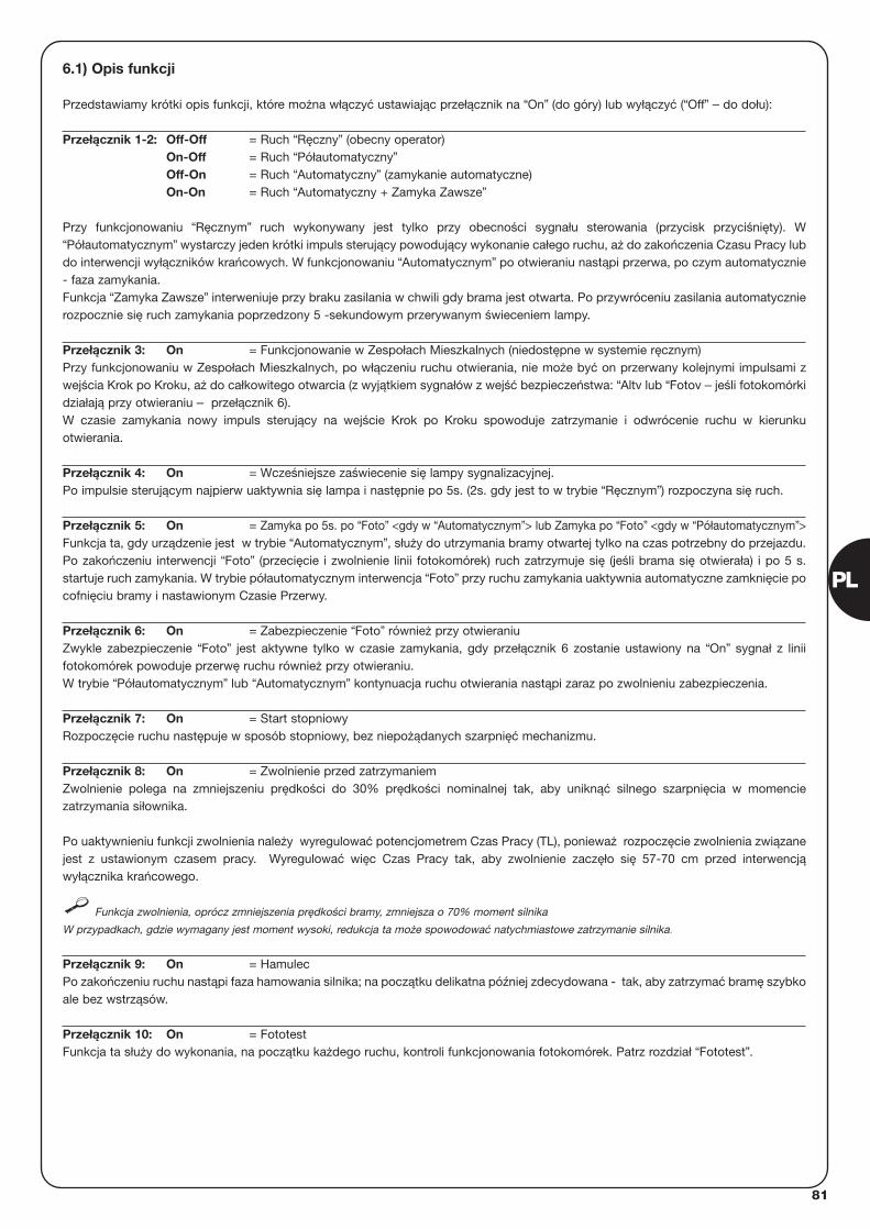
81
PL
6.1) Opis funkcji
Przedstawiamy krótki opis funkcji, które można włączyć ustawiając przełącznik na “On” (do góry) lub wyłączyć (“Off” – do dołu):
Przełącznik 1-2: Off-Off = Ruch “Ręczny” (obecny operator)On-Off = Ruch “Półautomatyczny”Off-On = Ruch “Automatyczny” (zamykanie automatyczne)On-On = Ruch “Automatyczny + Zamyka Zawsze”
Przy funkcjonowaniu “Ręcznym” ruch wykonywany jest tylko przy obecności sygnału sterowania (przycisk przyciśnięty). W“Półautomatycznym” wystarczy jeden krótki impuls sterujący powodujący wykonanie całego ruchu, aż do zakończenia Czasu Pracy lubdo interwencji wyłączników krańcowych. W funkcjonowaniu “Automatycznym” po otwieraniu nastąpi przerwa, po czym automatycznie- faza zamykania.Funkcja “Zamyka Zawsze” interweniuje przy braku zasilania w chwili gdy brama jest otwarta. Po przywróceniu zasilania automatycznierozpocznie się ruch zamykania poprzedzony 5 -sekundowym przerywanym świeceniem lampy.
Przełącznik 3: On = Funkcjonowanie w Zespołach Mieszkalnych (niedostępne w systemie ręcznym) Przy funkcjonowaniu w Zespołach Mieszkalnych, po włączeniu ruchu otwierania, nie może być on przerwany kolejnymi impulsami zwejścia Krok po Kroku, aż do całkowitego otwarcia (z wyjątkiem sygnałów z wejść bezpieczeństwa: “Altv lub “Fotov – jeśli fotokomórkidziałają przy otwieraniu – przełącznik 6).W czasie zamykania nowy impuls sterujący na wejście Krok po Kroku spowoduje zatrzymanie i odwrócenie ruchu w kierunkuotwierania.
Przełącznik 4: On = Wcześniejsze zaświecenie się lampy sygnalizacyjnej.Po impulsie sterującym najpierw uaktywnia się lampa i następnie po 5s. (2s. gdy jest to w trybie “Ręcznym”) rozpoczyna się ruch.
Przełącznik 5: On = Zamyka po 5s. po “Foto” <gdy w “Automatycznym”> lub Zamyka po “Foto” <gdy w “Półautomatycznym”> Funkcja ta, gdy urządzenie jest w trybie “Automatycznym”, służy do utrzymania bramy otwartej tylko na czas potrzebny do przejazdu.Po zakończeniu interwencji “Foto” (przecięcie i zwolnienie linii fotokomórek) ruch zatrzymuje się (jeśli brama się otwierała) i po 5 s.startuje ruch zamykania. W trybie półautomatycznym interwencja “Foto” przy ruchu zamykania uaktywnia automatyczne zamknięcie pocofnięciu bramy i nastawionym Czasie Przerwy.
Przełącznik 6: On = Zabezpieczenie “Foto” również przy otwieraniuZwykle zabezpieczenie “Foto” jest aktywne tylko w czasie zamykania, gdy przełącznik 6 zostanie ustawiony na “On” sygnał z liniifotokomórek powoduje przerwę ruchu również przy otwieraniu.W trybie “Półautomatycznym” lub “Automatycznym” kontynuacja ruchu otwierania nastąpi zaraz po zwolnieniu zabezpieczenia.
Przełącznik 7: On = Start stopniowyRozpoczęcie ruchu następuje w sposób stopniowy, bez niepożądanych szarpnięć mechanizmu.
Przełącznik 8: On = Zwolnienie przed zatrzymaniemZwolnienie polega na zmniejszeniu prędkości do 30% prędkości nominalnej tak, aby uniknąć silnego szarpnięcia w momenciezatrzymania siłownika.
Po uaktywnieniu funkcji zwolnienia należy wyregulować potencjometrem Czas Pracy (TL), ponieważ rozpoczęcie zwolnienia związanejest z ustawionym czasem pracy. Wyregulować więc Czas Pracy tak, aby zwolnienie zaczęło się 57-70 cm przed interwencjąwyłącznika krańcowego.
Funkcja zwolnienia, oprócz zmniejszenia prędkości bramy, zmniejsza o 70% moment silnika
W przypadkach, gdzie wymagany jest moment wysoki, redukcja ta może spowodować natychmiastowe zatrzymanie silnika.
Przełącznik 9: On = HamulecPo zakończeniu ruchu nastąpi faza hamowania silnika; na początku delikatna później zdecydowana - tak, aby zatrzymać bramę szybkoale bez wstrząsów.
Przełącznik 10: On = FototestFunkcja ta służy do wykonania, na początku każdego ruchu, kontroli funkcjonowania fotokomórek. Patrz rozdział “Fototest”.
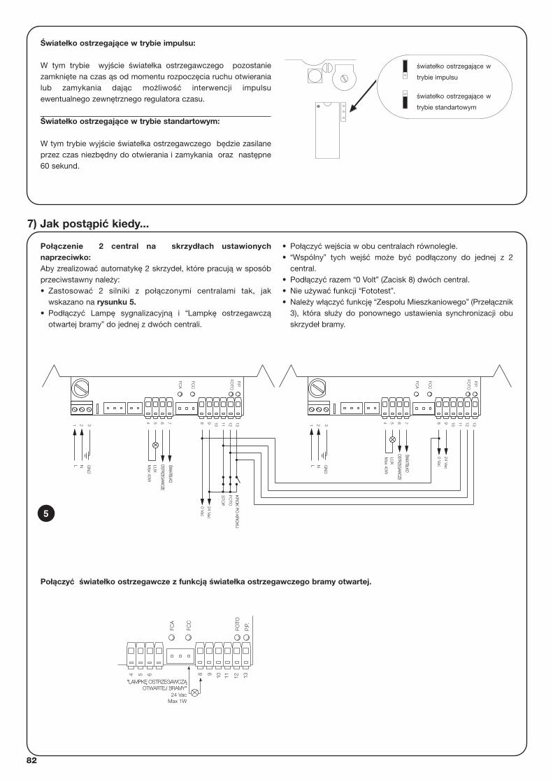
82
Połączenie 2 central na skrzydłach ustawionychnaprzeciwko:Aby zrealizować automatykę 2 skrzydeł, które pracują w sposóbprzeciwstawny należy:• Zastosować 2 silniki z połączonymi centralami tak, jak
wskazano na rysunku 5.• Podłączyć Lampę sygnalizacyjną i “Lampkę ostrzegawczą
otwartej bramy” do jednej z dwóch centrali.
• Połączyć wejścia w obu centralach równolegle.• “Wspólny” tych wejść może być podłączony do jednej z 2
central.• Podłączyć razem “0 Volt” (Zacisk 8) dwóch central.• Nie używać funkcji “Fototest”.• Należy włączyć funkcję “Zespołu Mieszkaniowego” (Przełącznik
3), która służy do ponownego ustawienia synchronizacji obuskrzydeł bramy.
7) Jak postąpić kiedy...
N
7
21 3
L
654
ŚŚWIATE
WIATEŁŁKOKO
OSTRZEG
AWCZE
OSTRZEG
AWCZE
13129 10 11S
TOP
P.P.
FOTO
Max 40W
LUX
GN
D
8
0 Vac
24 Vac
FCC
FCA
FOTO
KR
OK
PO
KR
OK
U
11
0 Vac
24 Vac
OSTRZEG
AWCZE
OSTRZEG
AWCZE
Max 40W
GN
D3
NL
1 2
LUX
ŚŚWIATE
WIATEŁŁKOKO
54 76 8 9 10
FCA
FCC
12 13FO
TO
P.P.
5
Światełko ostrzegające w trybie impulsu:
W tym trybie wyjście światełka ostrzegawczego pozostaniezamknięte na czas ąs od momentu rozpoczęcia ruchu otwieranialub zamykania dając możliwość interwencji impulsuewentualnego zewnętrznego regulatora czasu.
Światełko ostrzegające w trybie standartowym:
W tym trybie wyjście światełka ostrzegawczego będzie zasilaneprzez czas niezbędny do otwierania i zamykania oraz następne60 sekund.
światełko ostrzegające w
trybie impulsu
światełko ostrzegające w
trybie standartowym
FCC
FCA
P.P.
54 6 1198 10 12 13
24 Vac
"LAMPKLAMPKĘ OSTRZEGA OSTRZEGAWCZWCZĄOTWOTWARTEJ BRAMYARTEJ BRAMY"
Max 1W
FOTO
Połączyć światełko ostrzegawcze z funkcją światełka ostrzegawczego bramy otwartej.
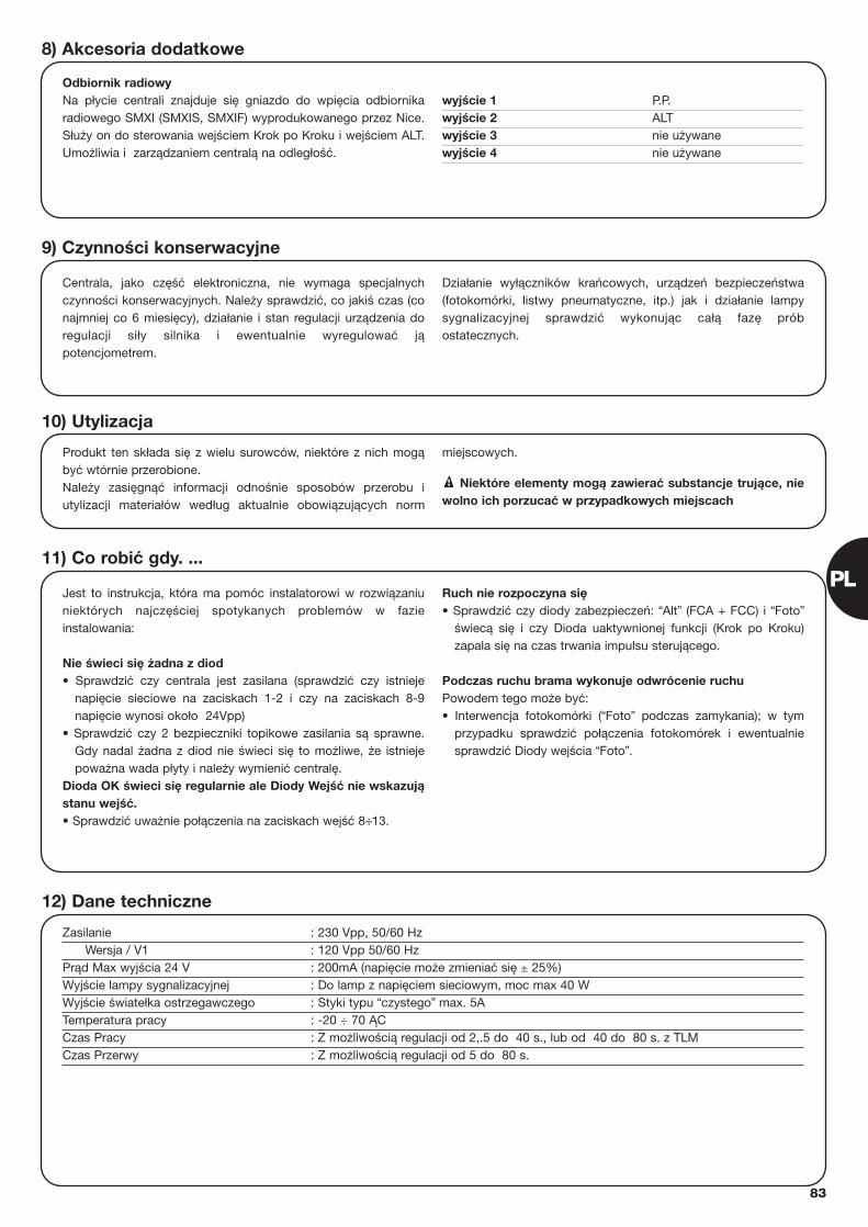
83
PL
Odbiornik radiowyNa płycie centrali znajduje się gniazdo do wpięcia odbiornikaradiowego SMXI (SMXIS, SMXIF) wyprodukowanego przez Nice.Służy on do sterowania wejściem Krok po Kroku i wejściem ALT.Umożliwia i zarządzaniem centralą na odległość.
wyjście 1 P.P.wyjście 2 ALTwyjście 3 nie używanewyjście 4 nie używane
8) Akcesoria dodatkowe
Centrala, jako część elektroniczna, nie wymaga specjalnychczynności konserwacyjnych. Należy sprawdzić, co jakiś czas (conajmniej co 6 miesięcy), działanie i stan regulacji urządzenia doregulacji siły silnika i ewentualnie wyregulować jąpotencjometrem.
Działanie wyłączników krańcowych, urządzeń bezpieczeństwa(fotokomórki, listwy pneumatyczne, itp.) jak i działanie lampysygnalizacyjnej sprawdzić wykonując całą fazę próbostatecznych.
9) Czynności konserwacyjne
Produkt ten składa się z wielu surowców, niektóre z nich mogąbyć wtórnie przerobione. Należy zasięgnąć informacji odnośnie sposobów przerobu iutylizacji materiałów według aktualnie obowiązujących norm
miejscowych.
Niektóre elementy mogą zawierać substancje trujące, niewolno ich porzucać w przypadkowych miejscach!
10) Utylizacja
Jest to instrukcja, która ma pomóc instalatorowi w rozwiązaniuniektórych najczęściej spotykanych problemów w fazieinstalowania:
Nie świeci się żadna z diod • Sprawdzić czy centrala jest zasilana (sprawdzić czy istnieje
napięcie sieciowe na zaciskach 1-2 i czy na zaciskach 8-9napięcie wynosi około 24Vpp)
• Sprawdzić czy 2 bezpieczniki topikowe zasilania są sprawne.Gdy nadal żadna z diod nie świeci się to możliwe, że istniejepoważna wada płyty i należy wymienić centralę.
Dioda OK świeci się regularnie ale Diody Wejść nie wskazująstanu wejść. • Sprawdzić uważnie połączenia na zaciskach wejść 8÷13.
Ruch nie rozpoczyna się• Sprawdzić czy diody zabezpieczeń: “Alt” (FCA + FCC) i “Foto”
świecą się i czy Dioda uaktywnionej funkcji (Krok po Kroku)zapala się na czas trwania impulsu sterującego.
Podczas ruchu brama wykonuje odwrócenie ruchu Powodem tego może być: • Interwencja fotokomórki (“Foto” podczas zamykania); w tym
przypadku sprawdzić połączenia fotokomórek i ewentualniesprawdzić Diody wejścia “Foto”.
11) Co robić gdy. ...
Zasilanie : 230 Vpp, 50/60 HzWersja / V1 : 120 Vpp 50/60 Hz
Prąd Max wyjścia 24 V : 200mA (napięcie może zmieniać się ± 25%)Wyjście lampy sygnalizacyjnej : Do lamp z napięciem sieciowym, moc max 40 WWyjście światełka ostrzegawczego : Styki typu “czystego” max. 5ATemperatura pracy : -20 ÷ 70 ĄCCzas Pracy : Z możliwością regulacji od 2,.5 do 40 s., lub od 40 do 80 s. z TLMCzas Przerwy : Z możliwością regulacji od 5 do 80 s.
12) Dane techniczne

84
smxi odbiornik radiowy
Opis produktu
Cechą charakterystyczną systemu z kodem dynamiczniezmiennym jest to, że kod wysyłany jest inny dla każdegonadajnika (i zmienia się po każdorazowym jego użyciu). Dlategoteż, aby odbiornik rozpoznał dany nadajnik należy wczytaćuprzednio kod rozpoznawczy. Czynność ta musi być powtórzonaprzy każdym nadajniku używanym do sterowania centralą.
Do pamięci odbiornika może być wczytanych maksymalnie 256
nadajników. Istnieje możliwość skasowania kodu pojedynczego nadajnika
za pomocą programatora SMU, lub wszystkich kodów.
W fazie wczytywania kodu nadajnika można wybrać jeden z 2sposobów:
Sposób I. Kolejny przycisk nadajnika uaktywnia odpowiedniewyjście w odbiorniku, to znaczy, że 1 przycisk uaktywnia 1wyjście, przycisk nr 2 uaktywnia wyjście 2, i tak dalej. Takiegoautomatycznego przypisania dokonujemy naciskając w procesieprogramowania dowolny przycisk pilota. Jeden wczytany pilotzajmie w pamięci tylko jedno miejsce.Sposób II. Dowolny przycisk pilota można powiązać z dowolnymkanałem odbiornika, na przykład przycisk 1 uaktywnia wyjście 2,przycisk 2 uaktywnia wyjście 1, itd. W tym przypadku wpisujemynadajnik (pilot) poprzez przyciśnięcie tego jego przycisku, któryma uruchamiać żądane (wybrane uprzednio) wyjście odbiornika.Oczywiście każdy przycisk może uaktywnić tylko jedno wyjście,ale to samo wyjście może być uaktywnione prze więcejprzycisków. Każdy przycisk zajmie jedną pozycję w pamięci.
Instalowanie anteny
Mając na uwadze poprawne działanie odbiornika niezbędne jestzastosowanie anteny typu ABF lub ABFKIT. Bez anteny zasięgzmniejszy się do kilku metrów. Antena ma być zamontowana najak największej wysokości i nad ewentualnymi elementamimetalowymi i żelbetonowymi. Aby przedłużyć przewód antenynależy zastosować przewód współosiowy z impedancją 50 omów(np. RG58 o niskiej stratności). Przewód ten nie może być dłuższyniż 10 m.
W przypadku, gdy antena jest umieszczona na nieuziemionymelemencie (np. mur),można dodatkowo podłączyć wtedy ekranprzewodu do innego punktu uziemienia, otrzymując jeszczelepszy zasięg. Oczywiście uziemienie (dobrej jakości) powinno sięznajdować w pobliżu. W przypadku, gdy nie można zamontowaćanteny ABF lub ABFKIT można uzyskać dosyć dobre wynikiużywając zamiast anteny odcinka przewodu znajdującego się wzestawie, który należy rozprostować i podłączyć do zacisku ANT.
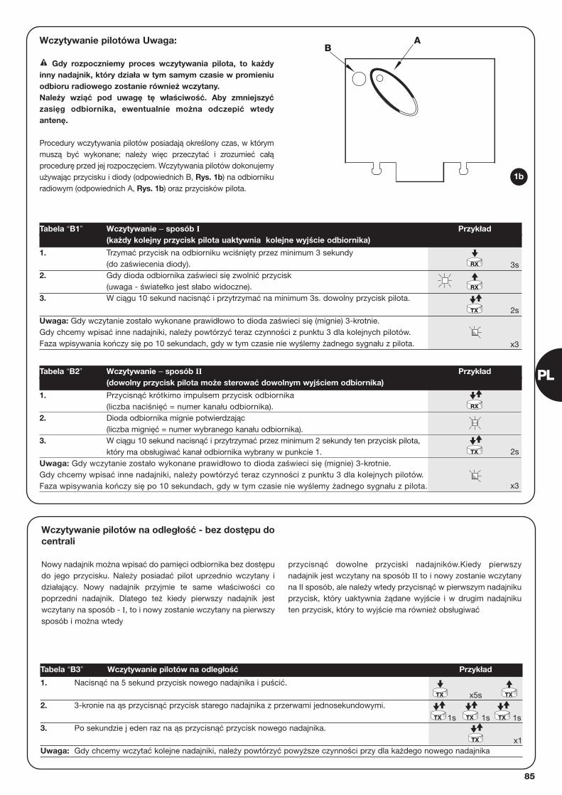
85
PL
AB
Wczytywanie pilotówa Uwaga:
Gdy rozpoczniemy proces wczytywania pilota, to każdyinny nadajnik, który działa w tym samym czasie w promieniuodbioru radiowego zostanie również wczytany. Należy wziąć pod uwagę tę właściwość. Aby zmniejszyćzasięg odbiornika, ewentualnie można odczepić wtedyantenę.
Procedury wczytywania pilotów posiadają określony czas, w którymmuszą być wykonane; należy więc przeczytać i zrozumieć całąprocedurę przed jej rozpoczęciem. Wczytywania pilotów dokonujemyużywając przycisku i diody (odpowiednich B, Rys. 1b) na odbiornikuradiowym (odpowiednich A, Rys. 1b) oraz przycisków pilota.
!
3s
2s
x3
2s
x3
1. Trzymać przycisk na odbiorniku wciśnięty przez minimum 3 sekundy(do zaświecenia diody).
2. Gdy dioda odbiornika zaświeci się zwolnić przycisk(uwaga - światełko jest słabo widoczne).
3. W ciągu 10 sekund nacisnąć i przytrzymać na minimum 3s. dowolny przycisk pilota.
Uwaga: Gdy wczytanie zostało wykonane prawidłowo to dioda zaświeci się (mignie) 3-krotnie.Gdy chcemy wpisać inne nadajniki, należy powtórzyć teraz czynności z punktu 3 dla kolejnych pilotów.Faza wpisywania kończy się po 10 sekundach, gdy w tym czasie nie wyślemy żadnego sygnału z pilota.
Tabela “B1” Wczytywanie – sposób I Przykład(każdy kolejny przycisk pilota uaktywnia kolejne wyjście odbiornika)
1. Przycisnąć krótkimo impulsem przycisk odbiornika (liczba naciśnięć = numer kanału odbiornika).
2. Dioda odbiornika mignie potwierdzając (liczba mignięć = numer wybranego kanału odbiornika).
3. W ciągu 10 sekund nacisnąć i przytrzymać przez minimum 2 sekundy ten przycisk pilota,który ma obsługiwać kanał odbiornika wybrany w punkcie 1.
Uwaga: Gdy wczytanie zostało wykonane prawidłowo to dioda zaświeci się (mignie) 3-krotnie.Gdy chcemy wpisać inne nadajniki, należy powtórzyć teraz czynności z punktu 3 dla kolejnych pilotów.Faza wpisywania kończy się po 10 sekundach, gdy w tym czasie nie wyślemy żadnego sygnału z pilota.
Tabela “B2” Wczytywanie – sposób II Przykład(dowolny przycisk pilota może sterować dowolnym wyjściem odbiornika)
RX
RX
TX
TX
RX
1b
x5s
1s 1s 1s
x1
1. Nacisnąć na 5 sekund przycisk nowego nadajnika i puścić.
2. 3-kronie na ąs przycisnąć przycisk starego nadajnika z przerwami jednosekundowymi.
3. Po sekundzie j eden raz na ąs przycisnąć przycisk nowego nadajnika.
Uwaga: Gdy chcemy wczytać kolejne nadajniki, należy powtórzyć powyższe czynności przy dla każdego nowego nadajnika
Tabela “B3” Wczytywanie pilotów na odległość Przykład
TX
TX TX TX
TX
TX
Wczytywanie pilotów na odległość - bez dostępu docentrali
Nowy nadajnik można wpisać do pamięci odbiornika bez dostępudo jego przycisku. Należy posiadać pilot uprzednio wczytany idziałający. Nowy nadajnik przyjmie te same właściwości copoprzedni nadajnik. Dlatego też kiedy pierwszy nadajnik jestwczytany na sposób - I, to i nowy zostanie wczytany na pierwszysposób i można wtedy
przycisnąć dowolne przyciski nadajników.Kiedy pierwszynadajnik jest wczytany na sposób II to i nowy zostanie wczytanyna II sposób, ale należy wtedy przycisnąć w pierwszym nadajnikuprzycisk, który uaktywnia żądane wyjście i w drugim nadajnikuten przycisk, który to wyjście ma również obsługiwać
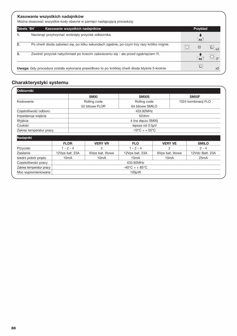
86
FLOR VERY VR FLO VERY VE SMILOPrzyciski 1 - 2 - 4 2 1 - 2 - 4 2 2 - 4Zasilanie 12Vps bat. 23A 6Vps bat. litowe 12Vps bat. 23A 6Vps bat. litowe 12Vdc Batt. 23Aśredni pobór prądu 10mA 10mA 15mA 10mA 25mACzęstotliwość pracy 433.92MHzZakres temperatur pracy -40°C ÷ + 85°CMoc wypromieniowana 100µW
Kasowanie wszystkich nadajnikówMożna skasować wszystkie kody obecne w pamięci następującą procedurą:
x3
3°
x5
1. Nacisnąć przytrzymać wciśnięty przycisk odbiornika.
2. Po chwili dioda zaświeci się, po kilku sekundach zgaśnie, po czym trzy razy krótko mignie.
3. Zwolnić przycisk natychmiast po trzecim zaświeceniu się - ale przed zgaśnięciem !!!.
Uwaga: Gdy procedura została wykonana prawidłowo to po krótkiej chwili dioda błyśnie 5-krotnie
Odbiorniki
Nadajniki
Tabela “B4” Kasowanie wszystkich nadajników Przykład
RX
RX
SMXI SMXIS SMXIFKodowanie Rolling code Rolling code 1024 kombinacji FLO
52 bitowe FLOR 64 bitowe SMILOCzęstotliwość odbioru 433.92MHzImpedancja wejścia 52ohmWyjścia 4 (na złączu SMXI)Czułość lepsza niż 0.5µVZakres temperatur pracy -10°C ÷ + 55°C
Charakterystyki systemu
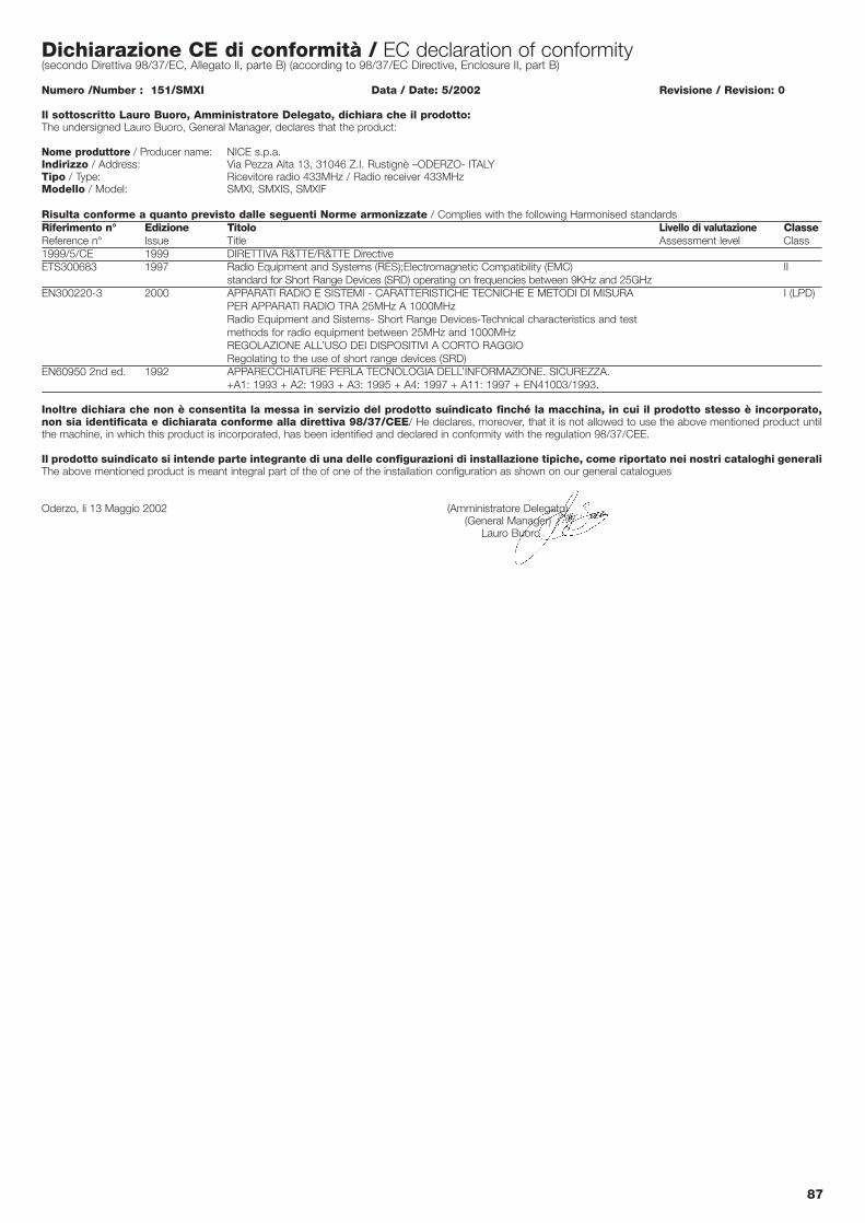
87
Dichiarazione CE di conformità / EC declaration of conformity(secondo Direttiva 98/37/EC, Allegato II, parte B) (according to 98/37/EC Directive, Enclosure II, part B)
Numero /Number : 151/SMXI Data / Date: 5/2002 Revisione / Revision: 0
Il sottoscritto Lauro Buoro, Amministratore Delegato, dichiara che il prodotto:The undersigned Lauro Buoro, General Manager, declares that the product:
Nome produttore / Producer name: NICE s.p.a.Indirizzo / Address: Via Pezza Alta 13, 31046 Z.I. Rustignè –ODERZO- ITALYTipo / Type: Ricevitore radio 433MHz / Radio receiver 433MHzModello / Model: SMXI, SMXIS, SMXIF
Risulta conforme a quanto previsto dalle seguenti Norme armonizzate / Complies with the following Harmonised standardsRiferimento n° Edizione Titolo Livello di valutazione ClasseReference n° Issue Title Assessment level Class1999/5/CE 1999 DIRETTIVA R&TTE/R&TTE DirectiveETS300683 1997 Radio Equipment and Systems (RES);Electromagnetic Compatibility (EMC) II
standard for Short Range Devices (SRD) operating on frequencies between 9KHz and 25GHzEN300220-3 2000 APPARATI RADIO E SISTEMI - CARATTERISTICHE TECNICHE E METODI DI MISURA I (LPD)
PER APPARATI RADIO TRA 25MHz A 1000MHzRadio Equipment and Sistems- Short Range Devices-Technical characteristics and test methods for radio equipment between 25MHz and 1000MHzREGOLAZIONE ALL’USO DEI DISPOSITIVI A CORTO RAGGIORegolating to the use of short range devices (SRD)
EN60950 2nd ed. 1992 APPARECCHIATURE PERLA TECNOLOGIA DELL’INFORMAZIONE. SICUREZZA. +A1: 1993 + A2: 1993 + A3: 1995 + A4: 1997 + A11: 1997 + EN41003/1993.
Inoltre dichiara che non è consentita la messa in servizio del prodotto suindicato finché la macchina, in cui il prodotto stesso è incorporato,non sia identificata e dichiarata conforme alla direttiva 98/37/CEE/ He declares, moreover, that it is not allowed to use the above mentioned product untilthe machine, in which this product is incorporated, has been identified and declared in conformity with the regulation 98/37/CEE.
Il prodotto suindicato si intende parte integrante di una delle configurazioni di installazione tipiche, come riportato nei nostri cataloghi generaliThe above mentioned product is meant integral part of the of one of the installation configuration as shown on our general catalogues
Oderzo, li 13 Maggio 2002 (Amministratore Delegato)(General Manager)
Lauro Buoro
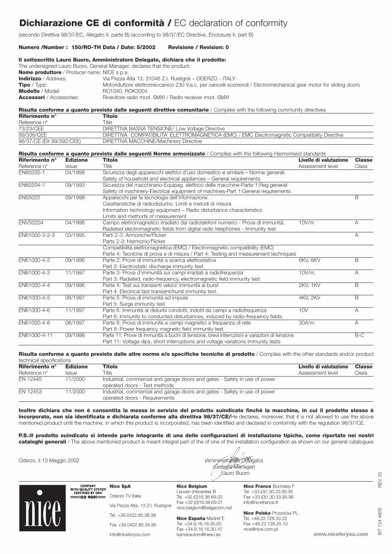
(secondo Direttiva 98/37/EC, Allegato II, parte B) (according to 98/37/EC Directive, Enclosure II, part B)
Numero /Number : 150/RO-TH Data / Date: 5/2002 Revisione / Revision: 0
Il sottoscritto Lauro Buoro, Amministratore Delegato, dichiara che il prodotto:The undersigned Lauro Buoro, General Manager, declares that the product:Nome produttore / Producer name: NICE s.p.a.Indirizzo / Address: Via Pezza Alta 13, 31046 Z.I. Rustignè – ODERZO - ITALYTipo / Type: Motoriduttore elettromeccanico 230 V.a.c. per cancelli scorrevoli / Electromechanical gear motor for sliding doorsModello / Model: RO1040, ROK3004Accessori / Accessories: Ricevitore radio mod. SMXI / Radio receiver mod. SMXI
Risulta conforme a quanto previsto dalle seguenti direttive comunitarie / Complies with the following community directivesRiferimento n° TitoloReference n° Title73/23/CEE DIRETTIVA BASSA TENSIONE/ Low Voltage Directive89/336/CEE DIRETTIVA COMPATIBILITA’ ELETTROMAGNETICA (EMC) / EMC Electromagnetic Compatibility Directive98/37/CE (EX 89/392/CEE) DIRETTIVA MACCHINE/Machinery Directive
Risulta conforme a quanto previsto dalle seguenti Norme armonizzate / Complies with the following Harmonised standardsRiferimento n° Edizione Titolo Livello di valutazione ClasseReference n° Issue Title Assessment level ClassEN60335-1 04/1998 Sicurezza degli apparecchi elettrici d’uso domestico e similare – Norme generali.
Safety of household and electrical appliances – General requirementsEN60204-1 09/1993 Sicurezza del macchinario-Equipag. elettrico delle macchine-Parte 1:Reg.generali
Safety of machinery-Electrical equipment of machines-Part 1:General requirementsEN55022 09/1998 Apparecchi per la tecnologia dell’informazione. B
Caratteristiche di radiodisturbo. Limiti e metodi di misuraInformation technology equipment – Radio disturbance characteristicsLimits and methods of measurement
ENV50204 04/1996 Campo elettromagnetico irradiato dai radiotelefoni numerici - Prova di immunità. 10V/m ARadiated electromagnetic fields from digital radio telephones - Immunity test
EN61000-3-2-3 03/1995 Parti 2-3: Armoniche/Flicker AParts 2-3: Harmonic/FlickerCompatibilità elettromagnetica (EMC) / Electromagnetic compatibility (EMC)Parte 4: Tecniche di prova e di misura / Part 4: Testing and measurement techniques
EN61000-4-2 09/1996 Parte 2: Prove di immunità a scarica elettrostatica 6KV, 8KV BPart 2: Electrostatic discharge immunity test
EN61000-4-3 11/1997 Parte 3: Prova d’immunità sui campi irradiati a radiofrequenza 10V/m, APart 3: Radiated, radio-frequency, electromagnetic field immunity test
EN61000-4-4 09/1996 Parte 4: Test sui transienti veloci/ immunità ai burst 2KV, 1KV BPart 4: Electrical fast transient/burst immunity test.
EN61000-4-5 06/1997 Parte 5: Prova di immunità ad impulsi 4KV, 2KV BPart 5: Surge immunity test
EN61000-4-6 11/1997 Parte 6: Immunità ai disturbi condotti, indotti da campi a radiofrequenza 10V APart 6: Immunity to conducted disturbances, induced by radio-frequency fields.
EN61000-4-8 06/1997 Parte 8: Prova di immunità a campi magnetici a frequenza di rete 30A/m APart 8: Power frequency magnetic field immunity test.
EN61000-4-11 09/1996 Parte 11: Prove di immunità a buchi di tensione, brevi interruzioni e variazioni di tensione B-CPart 11: Voltage dips, short interruptions and voltage variations immunity tests
Risulta conforme a quanto previsto dalle altre norme e/o specifiche tecniche di prodotto / Complies with the other standards and/or producttechnical specifications Riferimento n° Edizione Titolo Livello di valutazione ClasseReference n° Issue Title Assessment level ClassEN 12445 11/2000 Industrial, commercial and garage doors and gates - Safety in use of power
operated doors - Test methodsEN 12453 11/2000 Industrial, commercial and garage doors and gates - Safety in use of power
operated doors - Requirements
Inoltre dichiara che non è consentita la messa in servizio del prodotto suindicato finché la macchina, in cui il prodotto stesso èincorporato, non sia identificata e dichiarata conforme alla direttiva 98/37/CE/He declares, moreover, that it is not allowed to use the abovementioned product until the machine, in which this product is incorporated, has been identified and declared in conformity with the regulation 98/37/CE.
P.S.:Il prodotto suindicato si intende parte integrante di una delle configurazioni di installazione tipiche, come riportato nei nostricataloghi generali / The above mentioned product is meant integral part of the of one of the installation configuration as shown on our general catalogues
Oderzo, li 13 Maggio 2002 (Amministratore Delegato)(General Manager)
Lauro Buoro
Dichiarazione CE di conformità / EC declaration of conformity
IST
124
4858
RE
V. 0
0
Nice SpA
Oderzo TV Italia
Via Pezza Alta, 13 Z.I. Rustignè
Tel. +39.0422.85.38.38
Fax +39.0422.85.35.85
Nice BelgiumLeuven (Heverlee) BTel. +32.(0)16.38.69.00Fax +32.(0)[email protected]
Nice España Madrid ETel. +34.9.16.16.33.00Fax [email protected]
Nice France Buchelay FTel. +33.(0)1.30.33.95.95 Fax +33.(0)[email protected]
Nice Polska Pruszków PLTel. +48.22.728.33.22Fax [email protected]
www.niceforyou.com