Embed Size (px)
DESCRIPTION
Â
Citation preview

CATALOGUE TECHNIQUE GÉNÉRALGENERAL TECHNICAL CATALOGUE
1.07.12
PALIERS A ROTULE • TÊTES ARTICULÉES • CHAPES SPHERICAL PLAIN BEARINGS • ROD ENDS • CLEVISES
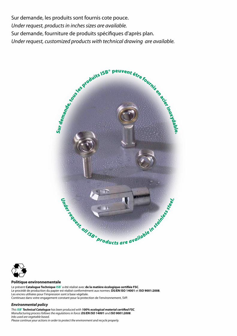
Sur demande, les produits sont fournis cote pouce. Under request, products in inches sizes are available.
Sur demande, fourniture de produits spécifiques d'après plan. Under request, customized products with technical drawing are available.
Sur
dem
ande
, tous l
es produits ISB® peuvent être fournis en acier inoxydab
le.
Under request, all ISB® products are available in
stain
less
ste
el.
Politique environnementaleLe présent Catalogue Technique ISB® a été réalisé avec de la matière écologique certifiée FSC.Le procédé de production du papier est réalisé conformément aux normes: DS/EN ISO 14001 et ISO 9001:2008.Les encres utilisées pour l'impression sont à base végétale.Continuez dans votre engagement constant pour la protection de l'environnement, SVP.
Environmental policyThis ISB® Technical Catalogue has been produced with 100% ecological material certified FSC.Manufacturing process follows the regulations in force: DS/EN ISO 14001 and ISO 9001:2008.Inks used are vegetable based. Please continue your actions in order to protect the environment and recycle properly.
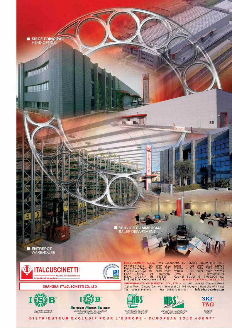
SIÈGE PRINCIPALHEAD OFFICE
ENTREPÔTWAREHOUSE
SERVICE COMMERCIALSALES DEPARTMENT
D I S T R I B U T E U R E X C L U S I F P O U R L ' E U R O P E - E U R O P E A N S O L E A G E N T *
ROULEMENTS ET COMPOSANTSBEARINGS AND COMPONENTS *
ROULEMENTS A AIGUILLES - ROUES LIBRESNEEDLE BEARINGS - FREE WHEELS *
���
COMPOSANTS POUR LE MOUVEMENT LINÉAIRECOMPONENTS FOR LINEAR MOTION *
ROULEMENTSBEARINGS
SHANGHAI ITALCUSCINETTI CO., LTD. - No. 89, Lane 85 Qianyun Road Xuj ing Town, Qingpu Distr ict - Shanghai 201702 (People’s Republ ic of China)Tél. 00862134313431 - Fax 00862134314431 - [email protected]
ITALCUSCINETTIforniture industriali
industrial supplies
S.p
.A.
SHANGHAI ITALCUSCINETTI CO., LTD.
ITALCUSCINETTI S.p.A. - Via Caponnetto, 15 - 42048 Rubiera (RE) ITALIEVe nte s I TA L I E Tél. 0039 0522 621811 - Fax 0039 0522 628926Export Sales Dept. Tél. 0039 0522 621830 - Fax 0039 0522 626149Purchasing Dept. Tél. 0039 0522 621880 - Fax 0039 0522 629255Code Fiscal et Numéro TVA CEE IT 00966080350R.E.A. C.C.I.A.A. RE 153325 - Capital Social € 1.000.000 i.v.i n f o @ i t a l c u s c i n e t t i . i t - w w w . i t a l c u s c i n e t t i . i t
ROULEMENTS POUR APPLICATIONS “FAIBLE NIVEAU SONORE”BEARINGS FOR “LOW NOISE” APPLICATIONS *
ElEctrical Motors standard
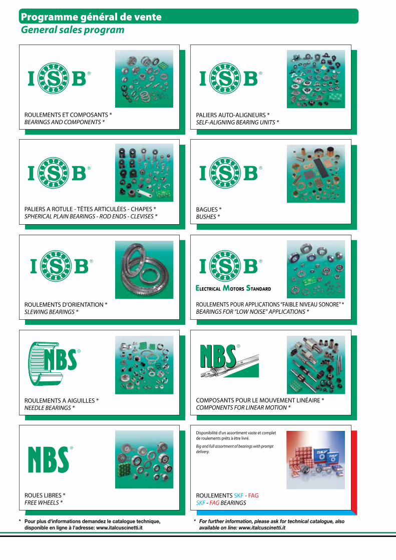
Programme général de venteGeneral sales program
* Pour plus d'informations demandez le catalogue technique, disponible en ligne à l'adresse: www.italcuscinetti.it
* For further information, please ask for technical catalogue, also available on line: www.italcuscinetti.it
ROULEMENTS SKF - FAGSKF - FAG BEARINGS
Disponibilité d'un assortiment vaste et complet de roulements prêts à être livré.
Big and full assortment of bearings with prompt delivery.
ROUES LIBRES *FREE WHEELS *
ROULEMENTS POUR APPLICATIONS “FAIBLE NIVEAU SONORE” *BEARINGS FOR “LOW NOISE” APPLICATIONS *
BAGUES *BUSHES *
ROULEMENTS D'ORIENTATION *SLEWING BEARINGS *
���
COMPOSANTS POUR LE MOUVEMENT LINÉAIRE *COMPONENTS FOR LINEAR MOTION *
ROULEMENTS ET COMPOSANTS *BEARINGS AND COMPONENTS *
ROULEMENTS A AIGUILLES *NEEDLE BEARINGS *
PALIERS AUTO-ALIGNEURS *SELF-ALIGNING BEARING UNITS *
PALIERS A ROTULE - TÊTES ARTICULÉES - CHAPES *SPHERICAL PLAIN BEARINGS - ROD ENDS - CLEVISES *
ElEctrical Motors standard

CATALOGUE TECHNIQUE GÉNÉRALGENERAL TECHNICAL CATALOGUE
Distributeur / Distributor

PAYS OÙ NOUS SOMMES PRÉSENTSCOUNTRIES WHERE WE ARE REPRESENTED
*heure légale (en Italie, période allant de mars à octobre) heure solaire (-1) les capitales avec l'horaire indiqué en rouge n'utilisent pas l'heure légale
*summer time (from March to October in Italy) standard time (-1) time is indicated in red for capitals with no daylight saving time (DST)
9
58
40
1
67
19
68
12
43
15
70
63
62
41
53
20
16
13
72
748
3
10
47
212
3235
59
27
31
30 51
44 6423
562234
36
69
18
4952 54
55
8
25
57160
17
3728
5733
39
65
466
24
6150

*heure légale (en Italie, période allant de mars à octobre) heure solaire (-1) les capitales avec l'horaire indiqué en rouge n'utilisent pas l'heure légale
*summer time (from March to October in Italy) standard time (-1) time is indicated in red for capitals with no daylight saving time (DST)
1
2
3
4
5
6
7
8
9
10
11
12
13
14
15
16
17
18
19
20
21
22
23
24
25
26
27
28
29
30
31
32
33
34
35
36
37
38
39
40
41
42
43
44
45
46
47
48
49
50
51
52
53
54
55
56
57
58
59
60
61
62
63
64
65
66
67
68
69
70
71
72
ALGÉRIE (Alger - 11h00)
ARABIE SAOUDITE (Riyadh - 13h00)
ARGENTINE (Buenos Aires - 07h00)
AUSTRALIE (Canberra - 20h00)
AUTRICHE (Vienne - 12h00)
BELGIQUE (Bruxelles - 12h00)
BRÉSIL (Brasilia - 07h00)
BULGARIE (Sofia - 13h00)
CANADA (Ottawa - 06h00)
CHILI (Santiago - 06h00)
CHINE (Pékin - 18h00)
CHYPRE (Nicosie -13h00 )
COLOMBIE (Bogotà - 05h00)
CORÉE DU SUD (Séoul - 19h00)
CÔTE D'IVOIRE (Abidjan - 10h00)
COSTA RICA (San José - 04h00)
CROATIE (Zagreb - 12h00)
DANEMARK (Copenhague - 12h00)
EGYPTE (Caire - 13h00)
EL SALVADOR (San Salvador - 04h00)
EMIRATS ARABES UNIS (Abu Dhabi - 14h00)
ESTONIE (Tallinn - 13h00)
FINLANDE (Helsinki - 13h00)
FRANCE (Paris - 12h00)
ALLEMAGNE (Berlin - 12h00)
JAPON (Tokyo - 19h00)
JORDANIE (Amman - 13h00)
GRÈCE (Athènes - 13h00)
INDE (Nouvelle-Delhi - 15h30)
IRLANDE (Dublin - 11h00)
ISLANDE (Reykjavik - 10h00)
ISRAËL (Jérusalem - 13h00)
ITALIE (Rome - 12h00)*
LETTONIE (Riga - 13h00)
LIBAN (Beyrouth - 13h00)
LITUANIE (Vilnius - 13h00)
MACÉDOINE (Skopje - 12h00)
MALAISIE (Kuala Lumpur - 18h00)
MALTE (La Valette - 12h00)
MAROC (Rabat - 10h00)
MEXIQUE (Mexico - 06h00)
NÉPAL (Katmandou - 15h45)
NIGERIA (Abuja - 11h00)
NORVÈGE (Oslo - 12h00)
NOUVELLE ZÉLANDE (Wellington - 22h00)
HOLLANDE (Amsterdam - 12h00)
PAKISTAN (Islamabad - 16h00)
PÉROU (Lima - 05h00)
POLOGNE (Varsovie - 12h00)
PORTUGAL (Lisbonne - 11h00)
ROYAUME UNI (Londres - 11h00)
REP. TCHÈQUE (Prague - 12h00)
REP. DOMINICAINE (Saint-Domingue - 06h00)
REP. DE SLOVAQUIE (Bratislava - 12h00)
ROUMANIE (Bucarest - 13h00)
RUSSIE (Moscou - 14h00)
SAINT-MARIN (Saint-Marin - 12h00)
SÉNÉGAL (Dakar - 10h00)
SYRIE (Damas - 13h00)
SLOVÉNIE (Lubiana - 12h00)
ESPAGNE (Madrid - 12h00)
ETATS-UNIS D'AMÉRIQUE (Washington - 06h00)
AFRIQUE DU SUD (Pretoria - 12h00)
SUÈDE (Stockholm - 12h00)
SUISSE (Berne - 12h00)
TAIWAN (Taipei - 18h00)
TUNISIE (Tunis - 11h00)
TURQUIE (Ankara - 13h00)
UKRAINE (Kiev - 13h00)
OUGANDA (Kampala - 14h00)
HONGRIE (Budapest - 12h00)
VENEZUELA (Caracas - 06h00)
29
11
42
66
38
2614
4
45
ALGERIA
SAUDI ARABIA
ARGENTINA
AUSTRALIA
AUSTRIA
BELGIUM
BRAZIL
BULGARIA
CANADA
CHILE
CHINA
CYPRUS
COLOMBIA
SOUTH KOREA
IVORY COAST
COSTA RICA
CROATIA
DENMARK
EGYPT
EL SALVADOR
UNITED ARAB EMIRATES
ESTONIA
FINLAND
FRANCE
GERMANY
JAPAN
JORDAN
GREECE
INDIA
IRELAND
ICELAND
ISRAEL
ITALY
LATVIA
LEBANON
LITHUANIA
MACEDONIA
MALAYSIA
MALTA
MOROCCO
MEXICO
NEPAL
NIGERIA
NORWAY
NEW ZEALAND
NETHERLANDS
PAKISTAN
PERU
POLAND
PORTUGAL
UNITED KINGDOM
CZECH REPUBLIC
DOMINICAN REPUBLIC
SLOVAKIAN REPUBLIC
RUMANIA
RUSSIA
SAN MARINO
SENEGAL
SYRIA
SLOVENIA
SPAIN
UNITED STATES OF AMERICA
SOUTH AFRICA
SWEDEN
SWITZERLAND
TAIWAN
TUNISIA
TURKEY
UKRAINE
REPUBLIC OF UGANDA
HUNGARY
VENEZUELA
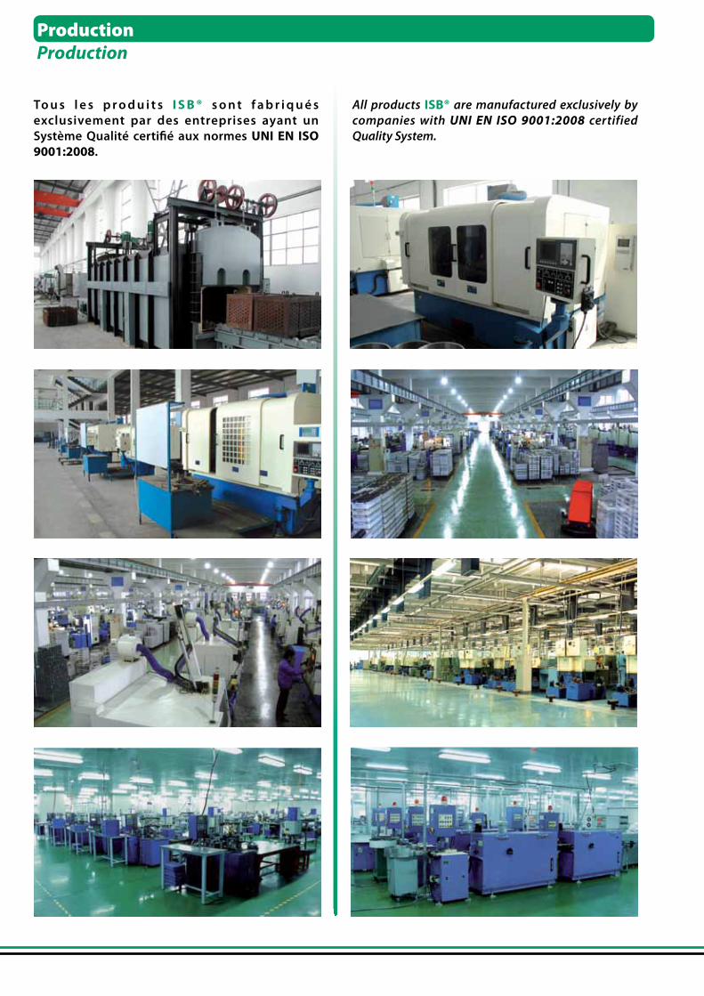
To u s l e s p r o d u i t s I S B ® s o n t f a b r i q u é s exclusivement par des entreprises ayant un Système Qualité certifié aux normes UNI EN ISO 9001:2008.
All products ISB® are manufactured exclusively by companies with UNI EN ISO 9001:2008 certified Quality System.
ProductionProduction
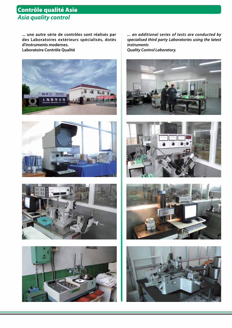
... une autre série de contrôles sont réalisés par des Laboratoires extérieurs spécialisés, dotés d'instruments modernes.Laboratoire Contrôle Qualité
... an additional series of tests are conducted by specialised third party Laboratories using the latest instrumentsQuality Control Laboratory.
Contrôle qualité AsieAsia quality control
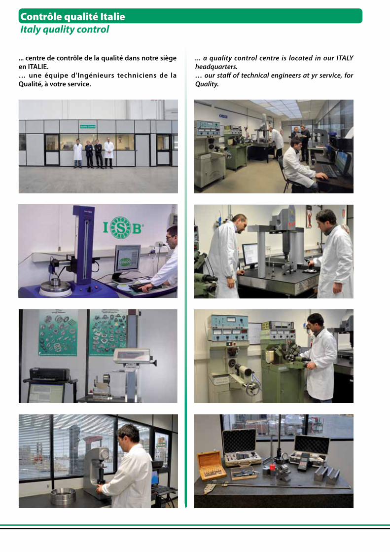
... centre de contrôle de la qualité dans notre siège en ITALIE.… une équipe d'Ingénieurs techniciens de la Qualité, à votre service.
... a quality control centre is located in our ITALY headquarters.… our staff of technical engineers at yr service, for Quality.
Contrôle qualité ItalieItaly quality control
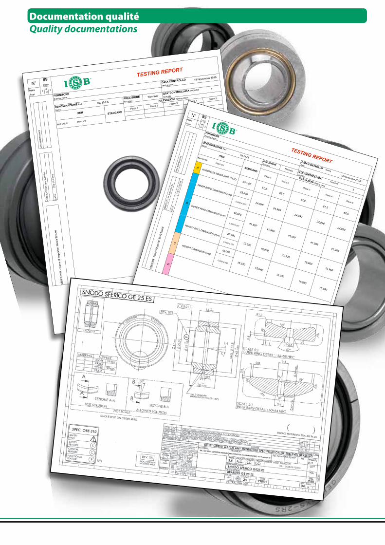
Documentation qualitéQuality documentations
DA
TA
18-1
1-2
010
N°
STANDARD
2Pagina
TESTING REPORT
89
2010
di
of
FORNITORE
Supplier name
DATA CONTROLLO
Testing Date:
DENOMINAZIONE Part
Name
PRECISIONE
Accuracy
Normale
GE 25 ES
QTA' CONTROLLATA Inspected
Quantity:
18 Novembre 2010
5
RILEVAZIONI Testing Value
Piece 3Piece 4
Piece 5
Page
2
Lis
ta d
istr
ibuzio
ne
Piece 1
VERIF
ICA
TO
DA
appro
ved b
y:
Piece 2
ITEM
BAR CODE 81007135
VÉRI
FIÉ
PAR
- N
ame
of In
spec
tor:
Nic
ola
Bavu
tti
19,950
15,940
15,930
15,940
15,950
15,960
HEIGHT DIMENSION (mm)
16,000
0,000/-0,240
20,000
C
19,920
19,960
HEIGHT BALL DIMENSION (mm)
19,950
19,970
DATA CONTROLLO Testing
Date:
DENOMINAZIONE Part
Name
PRECISIONE Accuracy
Normale
GE 25 ES
QTA' CONTROLLATA Inspected
Quantity:18 Novembre 2010
VERIF
ICA
TO
DA
appro
ved b
y:
DA
TA
A
5
RILEVAZIONI Testing Value
62,0
Piece 5B
25,000
0,000/-0,010
18/11/20
OUTER RING DIMENSION (mm)
41,997
Piece 4
0,000/-0,011
41,999
41,997
41,998
61,5
41,996
0,000/-0,120
D
Piece 1
Piece 2
Piece 3
42,000
HARDNESS INNER RING (HRC)
Lis
ta d
istr
ibuzio
ne
N°Pagina
Page
BAR CODE 81007135
INNER BORE DIMENSION (mm)
STANDARD
2
ITEM
FORNITORE
Supplier name
892010
1 di of
60 ÷ 63
TESTING REPORT
24,998
24,994
24,993
24,996
24,994
61,5
62,5
61,0
10
VÉRIF
IÉ PA
R - N
ame o
f Insp
ecto
r: Nico
la Ba
vutti

ApplicationsApplications
AGRICULTURE AGRICULTUREMAISON HOMEINDUSTRIE INDUSTRYMACHINES MACHINERIESLOISIRS FREE TIMEBUREAU OFFICEVÉHICULES VEHICLES
Les nombreuses lignes de roulements et de composants ISB® permettent de satisfaire les exigences dans les secteurs d'application les plus variés. La vaste gamme et la qualité des produits est en mesure de garantir les applications même dans les conditions d'utilisation les plus contraignantes. Les roulements et composants ISB®, compte une production structurée et complète de toutes les typologies, apte à répondre aux exigences d'application les plus variées.
The diverse product lines of ISB® bearings and components, make it possible to satisfy the needs of a wide variety of fields of application. The wide range and quality of products is also a guarantee for heavy duty applications. ISB® bearings and components are available in versions across-the-board and can meet the requirements of a wide variety of demanding applications.
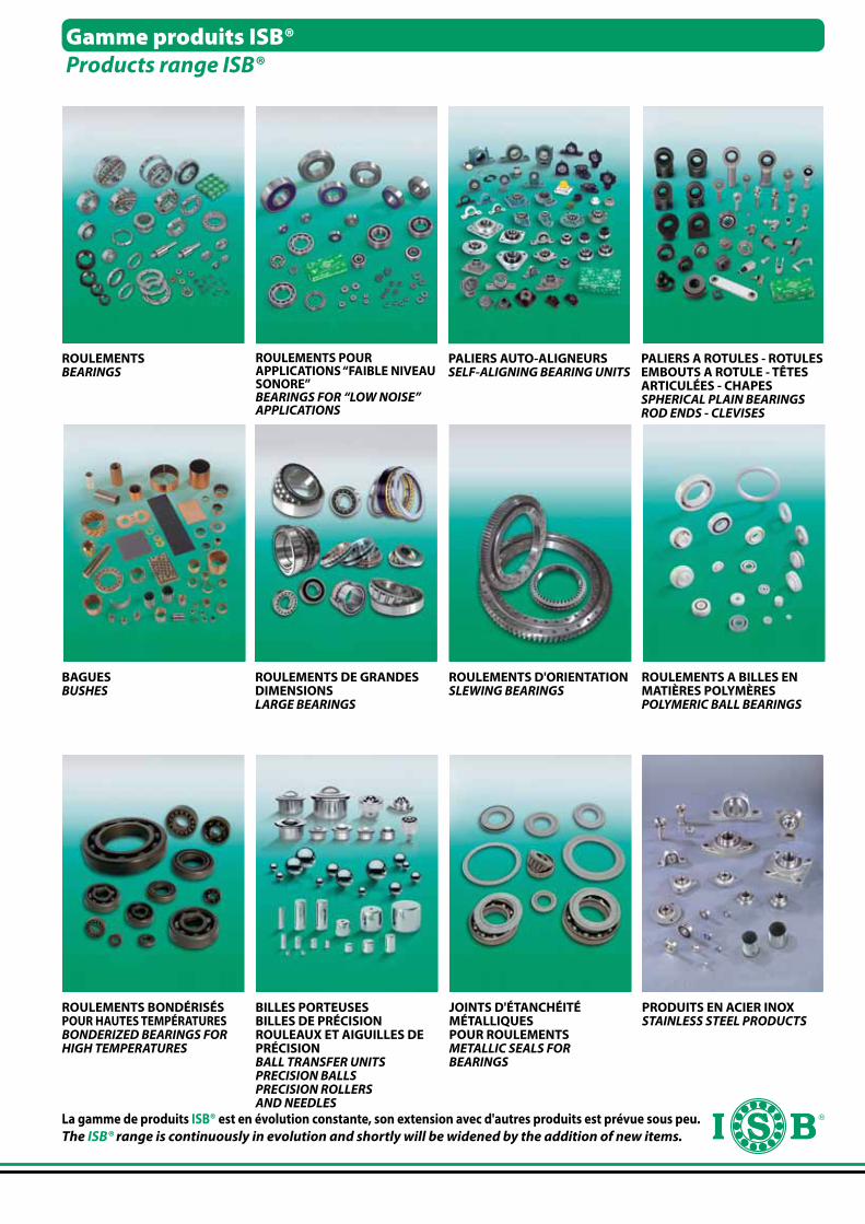
Gamme produits ISB®Products range ISB®
ROULEMENTSBEARINGS
JOINTS D'ÉTANCHÉITÉ MÉTALLIQUES POUR ROULEMENTSMETALLIC SEALS FORBEARINGS
BAGUESBUSHES
ROULEMENTS A BILLES ENMATIÈRES POLYMÈRESPOLYMERIC BALL BEARINGS
ROULEMENTS DE GRANDESDIMENSIONSLARGE BEARINGS
ROULEMENTS D'ORIENTATIONSLEWING BEARINGS
PALIERS AUTO-ALIGNEURSSELF-ALIGNING BEARING UNITS
ROULEMENTS BONDÉRISÉS POUR HAUTES TEMPÉRATURESBONDERIZED BEARINGS FORHIGH TEMPERATURES
PRODUITS EN ACIER INOXSTAINLESS STEEL PRODUCTS
PALIERS A ROTULES - ROTULESEMBOUTS A ROTULE - TÊTES ARTICULÉES - CHAPESSPHERICAL PLAIN BEARINGSROD ENDS - CLEVISES
BILLES PORTEUSESBILLES DE PRÉCISIONROULEAUX ET AIGUILLES DE PRÉCISIONBALL TRANSFER UNITSPRECISION BALLSPRECISION ROLLERSAND NEEDLES
La gamme de produits ISB® est en évolution constante, son extension avec d'autres produits est prévue sous peu.The ISB® range is continuously in evolution and shortly will be widened by the addition of new items.
ROULEMENTS POUR APPLICATIONS “FAIBLE NIVEAU SONORE” BEARINGS FOR “LOW NOISE” APPLICATIONS

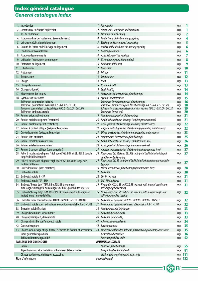
1. Introduction 1. Introduction page 1 2. Dimensions, tolérances et précision 2. Dimensions, tollerances and precisions page 1 3. Jeu du roulement 3. Clearance of the bearing page 2 4. Fixation radiale des roulements (accouplements) 4. Radial fixing of the bearings (coupling) page 4 5. Usinage et réalisation du logement 5. Working and execution of the housing page 5 6. Qualité de l'arbre et de l'alésage du logement 6. Quality of the shaft and the housing opening page 6 7. Conditions d'accouplement 7. Coupling conditions pag. 6 8. Fixations des roulements 8. Axial fixtures of the bearings page 7 9. Utilisation (montage et démontage) 9. Use (mounting and dismounting) page 810. Protection du logement 10. Protection of the seat page 911. Lubrification 11. Lubrication page 1012. Frottement 12. Friction page 1113. Température 13. Temperature page 1214. Charge 14. Load page 1315. Charge dynamique C 15. Dynamic load C page 1316. Charge statique C
016. Static load C
0page 14
17. Mouvements des rotules 17. Movements of the spherical plain bearings page 14 18. Symboles et tolérances 18. Symbols and tolerances page 15 Tolérances pour rotules radiales Tolerances for radial spherical plain bearings page 16 Tolérances pour rotules axiales (GX..S - GX..CP - GX..SP) Tolerances for spherical plain thrust bearings (GX..S - GX..CP - GX..SP) page 18 Tolérances pour rotules à contact oblique (GAC..S - GAC..CP - GAC..SP) Tolerance for angular contact spherical plain bearings (GAC..S - GAC..CP - GAC..SP) page 19 Tolérances embouts à rotule Tolerances for rod ends page 2019. Rotules exigeant l'entretien 19. Maintenance spherical plain bearings page 2120. Rotules radiales (exigeant l'entretien) 20. Radial spherical plain bearings (requiring maintenance) page 2121. Rotules axiales (exigeant l'entretien) 21. Axial spherical plain bearings (requiring maintenance) page 2222. Rotules à contact oblique (exigeant l'entretien) 22. Angular contact spherical plain bearings (requiring maintenance) page 2223. Durée des rotules (exigeant l'entretien) 23. Life of the spherical plain bearings (requiring maintenance) page 2324. Rotules sans entretien 24. Maintenance-free spherical plain bearings page 2525. Rotules radiales (sans entretien) 25. Radial spherical plain bearings (maintenance-free) page 2626. Rotules axiales (sans entretien) 26. Axial spherical plain bearings (maintenance-free) page 2627. Rotules à contact oblique (sans entretien) 27. Angular contact spherical plain bearings (maintenance-free) page 2728. Palier à rotule auto-aligneur “high speed” GE..BBH et GE..BBL à double
rangée de billes intégrée28. High-speed GE..BBH and GE..BBL centripetal ball joint with integral
double-row ball bearingpage 27
29. Palier à rotule auto-aligneur “high speed” GE..RB à une rangée de rouleaux intégrée
29. High-speed GE..RB centripetal ball joint with integral single-row roller bearing
page 2730. Durée des rotules (sans entretien) 30. Life of the spherical plain bearings (maintenance-free) page 2831. Embouts à rotule 31. Rod ends page 3032. Embouts à rotule SI - SA 32. SI - SA rod ends page 3133. Embouts à rotule TSF - TSM 33. TSF -TSM rod ends page 3134. Embouts “heavy duty” TSM..BB et TSF..BB à roulement
auto-aligneur intégré à deux rangées de billes pour hautes vitesses34. Heavy-duty TSM..BB and TSF..BB rod ends with integral double-row
self-aligning ball bearingpage 31
35. Embouts “heavy duty” TSM..RB et TSF..RB à roulement auto-aligneur intégré à une rangée de billes
35. Heavy-duty TSM..RB and TSF..RB rod ends with integral single-row self-aligning roller bearing
page 32
36. Embouts à rotule pour hydraulique TAPR.N - TAPR.U - TAPR.DO - TAPR.CE 36. Rod ends for hydraulic TAPR.N - TAPR.U - TAPR.DO - TAPR.CE page 3237. Embouts à rotule pour hydraulique à corps forgé soudable T.A.C. - T.P.N. 37. Rod ends for hydraulic with weld able housing T.A.C. - T.P.N. page 3238. Entretien et lubrification 38. Maintenance and lubrication page 3339. Charge dynamique C des embouts 39. Rod ends dynamic load C page 3340. Charge dynamique C
0 des embouts 40. Rod ends static load C
0page 33
41. Charge admissible sur l'embout à rotule 41. Allowed load on rod ends page 3442. Causes de rupture 42. Breaking causes page 3543. Chapes avec alésage et tige filetée, éléments de fixation et accessoires 43. Clevises with threaded hole and pins with complementary accessories page 35 Index général des produits General products index page 36 Tableau d'interchangeabilité Interchangeability table page 52 TABLEAUX DES DIMENSIONS DIMENSIONAL TABLES Rotules Spherical plain bearings page 55 Tiges d'embouts et articulations sphériques - Têtes articulées Ball joint rod ends - Rod ends page 81 Chapes et éléments de fixation accessoires Clevises and complementary accessories page 111Fiche d'information Informative card page 122
Index général catalogueGeneral catalogue index
1
La marque ISB® comprend une vaste gamme de produits d'excellente qualité. La production est développée par un groupe de constructeurs qui ont su mettre leur expérience de plusieurs décennies au service de ce secteur spécifique. Les ateliers de ces usines sont dotés de machines modernes en mesure de gérer et de contrôler toutes les phases de fabrication, garantissant des produis finis d'une grande précision et qualité. Les Bureaux d'Etudes présents dans ces établissements, sont voués à une recherche continue, dans le but précis d'obtenir une amélioration constante des standards de production et du renouvellement technologique des équipements destinés à la production. Les Bureaux d'Etudes sont côtoyés par des laboratoires spécialisés dans le contrôle de la qualité des produits finis, afin de prévenir la mise en circulation de produits ne respectant pas les standards de fabrication. Les Laboratoires de contrôle qualité sont dotés des équipements les plus modernes. Tous les produits ISB® sont fabriqués dans le respect de la norme RoHS.
1. Introduction1. Introduction
2. Dimensions, tolérances et précision2. Dimensions, tollerances and precisions
Les rotules sont des composants mécaniques orientables, prêts à être montés. Leurs dimensions sont normalisées et elles permettent la transmission des forces statiques et dynamiques, ainsi que les mouvements oscillatoires d'alignement, rotatoire et de déversement multidirectionnel. La bague intérieure est dotée d'une surface extérieure sphérique convexe et la bague extérieure est elle aussi sphérique, mais sa surface interne est concave. Des surfaces de glissement réalisées dans la combinaison acier sur acier et dans beaucoup d'autres exécutions sans entretien sont disponibles. Les embouts sont formées d'un corps en forme de tête, défini pièce de fonderie, dans lequel est insérée en mode permanent une rotule, dont la précision dimensionnelle et de forme du diamètre intérieur et extérieur, fait référence aux mêmes normes DIN que celles des roulements.
The ISB® brand includes a wide range of excellent quality products. Our production is divided among a pool of constructors who have accumulated decades of experience in this specific sector.Production takes place in factories equipped with modern machinery capable of managing and controlling every phase of construction guaranteeing precision and quality in the finished product.The factories have Technical Offices dedicating their time to continuous research with the precise goal of obtaining constant improvement in the standards of production. They also have the task of overseeing upgrading and technological renewal of the equipment used for production.Specialized Laboratories stand along side the Technical Offices to control the quality of finished products. The objective of these Laboratories is to prevent, by every possible means, the circulation of sub-standard products.These Laboratories are furnished with modern, state of the art, instruments to control quality. All ISB® products are constructed according to RoHS normatives.
Spherical plain bearings are guidable mechanical components ready to be applied. The dimensions are unified and permit the transmission of both static and dynamic strength in conjunction with oscillating alignment, rotar y and bouncing movements in several directions. The internal ring is provided with an external convex spherical surface while the external ring is equally spherical with a concave internal surface. They are available with sliding surfaces realized in a combination of steel on steel and in many other executions which do not require maintenance.The rod ends consist of a body, also defined as housing, in the form of a head in which is permanently inserted, in the proper seat, a spherical plain bearing, with dimensional precision and in the shape of the internal and external diameter, which comply with the same DIN specifications for
2
3. Jeu du roulement3. Clearance of the bearing
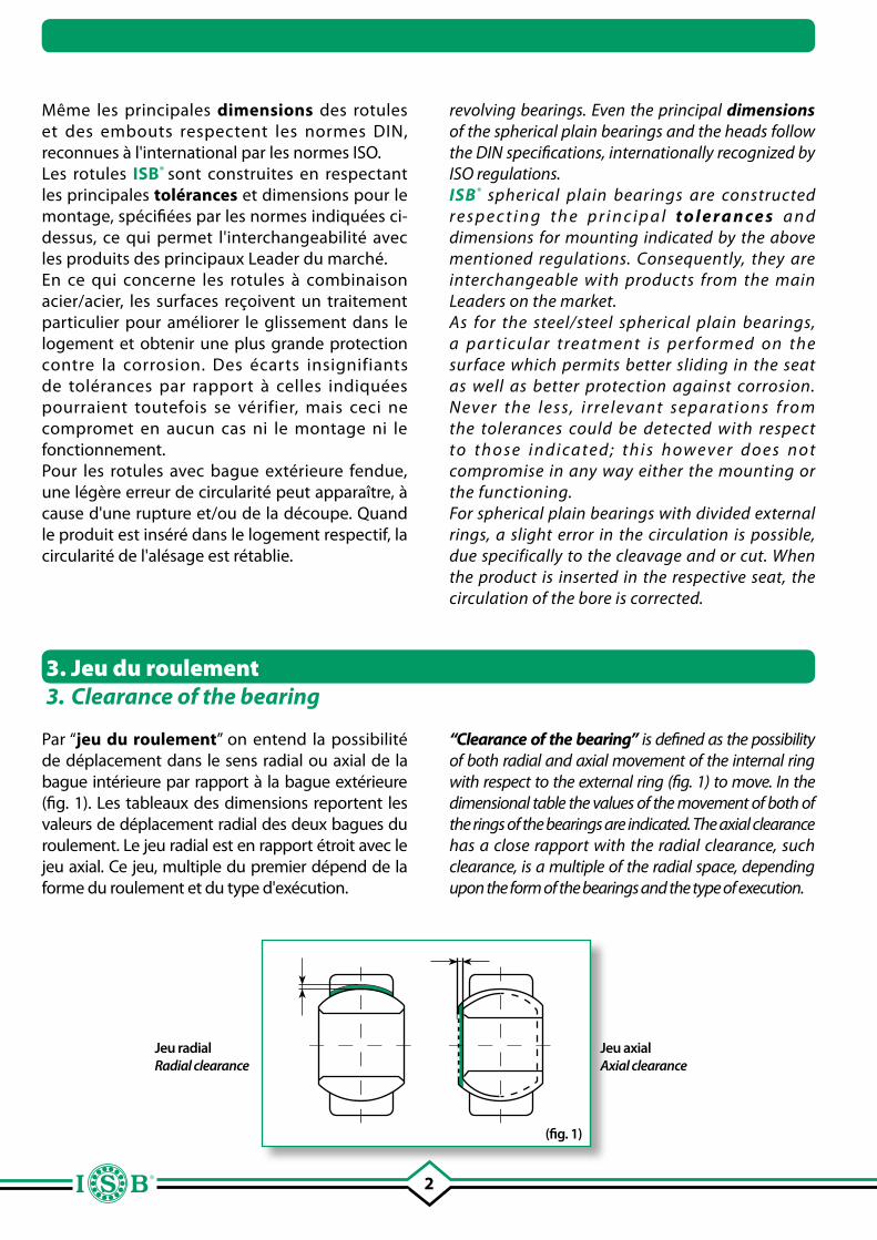
Par “jeu du roulement” on entend la possibilité de déplacement dans le sens radial ou axial de la bague intérieure par rapport à la bague extérieure (fig. 1). Les tableaux des dimensions reportent les valeurs de déplacement radial des deux bagues du roulement. Le jeu radial est en rapport étroit avec le jeu axial. Ce jeu, multiple du premier dépend de la forme du roulement et du type d'exécution.
(fig. 1)
Jeu radialRadial clearance
Jeu axialAxial clearance
Même les principales dimensions des rotules et des embouts respectent les normes DIN, reconnues à l'international par les normes ISO.Les rotules ISB® sont construites en respectant les principales tolérances et dimensions pour le montage, spécifiées par les normes indiquées ci-dessus, ce qui permet l'interchangeabilité avec les produits des principaux Leader du marché.En ce qui concerne les rotules à combinaison acier/acier, les surfaces reçoivent un traitement particulier pour améliorer le glissement dans le logement et obtenir une plus grande protection contre la corrosion. Des écarts insignifiants de tolérances par rapport à celles indiquées pourraient toutefois se vérifier, mais ceci ne compromet en aucun cas ni le montage ni le fonctionnement.Pour les rotules avec bague extérieure fendue, une légère erreur de circularité peut apparaître, à cause d'une rupture et/ou de la découpe. Quand le produit est inséré dans le logement respectif, la circularité de l'alésage est rétablie.
“Clearance of the bearing” is defined as the possibility of both radial and axial movement of the internal ring with respect to the external ring (fig. 1) to move. In the dimensional table the values of the movement of both of the rings of the bearings are indicated. The axial clearance has a close rapport with the radial clearance, such clearance, is a multiple of the radial space, depending upon the form of the bearings and the type of execution.
revolving bearings. Even the principal dimensions of the spherical plain bearings and the heads follow the DIN specifications, internationally recognized by ISO regulations.ISB® spherical plain bearings are constructed r e s p e c t i n g t h e p r i n c i p a l t o l e r a n c e s a n d dimensions for mounting indicated by the above mentioned regulations. Consequently, they are interchangeable with products from the main Leaders on the market.As for the steel/steel spherical plain bearings, a par ticular treatment is per formed on the surface which permits better sliding in the seat as well as better protection against corrosion. Never the less, i rrelevant separations from the tolerances could be detected with respect t o t h o s e i n d i ca t e d ; t h i s h owe ve r d o e s n o t compromise in any way either the mounting or the functioning.For spherical plain bearings with divided external rings, a slight error in the circulation is possible, due specifically to the cleavage and or cut. When the product is inserted in the respective seat, the circulation of the bore is corrected.
3
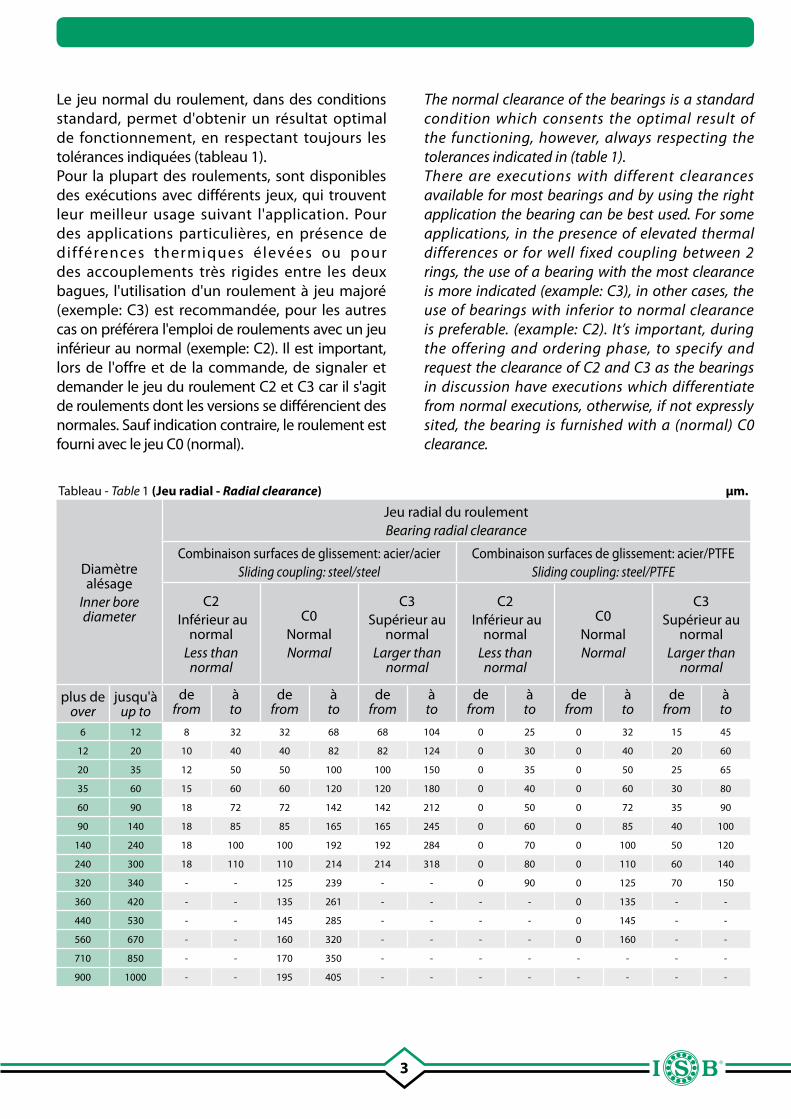
Le jeu normal du roulement, dans des conditions standard, permet d'obtenir un résultat optimal de fonctionnement, en respectant toujours les tolérances indiquées (tableau 1).Pour la plupart des roulements, sont disponibles des exécutions avec différents jeux, qui trouvent leur meilleur usage suivant l'application. Pour des applications particulières, en présence de différences thermiques élevées ou pour des accouplements très rigides entre les deux bagues, l'utilisation d'un roulement à jeu majoré (exemple: C3) est recommandée, pour les autres cas on préférera l'emploi de roulements avec un jeu inférieur au normal (exemple: C2). Il est important, lors de l'offre et de la commande, de signaler et demander le jeu du roulement C2 et C3 car il s'agit de roulements dont les versions se différencient des normales. Sauf indication contraire, le roulement est fourni avec le jeu C0 (normal).
Tableau - Table 1 (Jeu radial - Radial clearance) µm.
Diamètre alésage
Inner bore diameter
Jeu radial du roulement Bearing radial clearance
Combinaison surfaces de glissement: acier/acierSliding coupling: steel/steel
Combinaison surfaces de glissement: acier/PTFESliding coupling: steel/PTFE
C2 Inférieur au
normalLess than
normal
C0 NormalNormal
C3 Supérieur au
normalLarger than
normal
C2 Inférieur au
normalLess than
normal
C0 NormalNormal
C3 Supérieur au
normalLarger than
normal
plus deover
jusqu'àup to
defrom
àto
defrom
àto
defrom
àto
defrom
àto
defrom
àto
defrom
àto
6 12 8 32 32 68 68 104 0 25 0 32 15 45
12 20 10 40 40 82 82 124 0 30 0 40 20 60
20 35 12 50 50 100 100 150 0 35 0 50 25 65
35 60 15 60 60 120 120 180 0 40 0 60 30 80
60 90 18 72 72 142 142 212 0 50 0 72 35 90
90 140 18 85 85 165 165 245 0 60 0 85 40 100
140 240 18 100 100 192 192 284 0 70 0 100 50 120
240 300 18 110 110 214 214 318 0 80 0 110 60 140
320 340 - - 125 239 - - 0 90 0 125 70 150
360 420 - - 135 261 - - - - 0 135 - -
440 530 - - 145 285 - - - - 0 145 - -
560 670 - - 160 320 - - - - 0 160 - -
710 850 - - 170 350 - - - - - - - -
900 1000 - - 195 405 - - - - - - - -
The normal clearance of the bearings is a standard condition which consents the optimal result of the functioning, however, always respecting the tolerances indicated in (table 1). There are executions with different clearances available for most bearings and by using the right application the bearing can be best used. For some applications, in the presence of elevated thermal differences or for well fixed coupling between 2 rings, the use of a bearing with the most clearance is more indicated (example: C3), in other cases, the use of bearings with inferior to normal clearance is preferable. (example: C2). It’s important, during the offering and ordering phase, to specify and request the clearance of C2 and C3 as the bearings in discussion have executions which differentiate from normal executions, otherwise, if not expressly sited, the bearing is furnished with a (normal) C0 clearance.
4
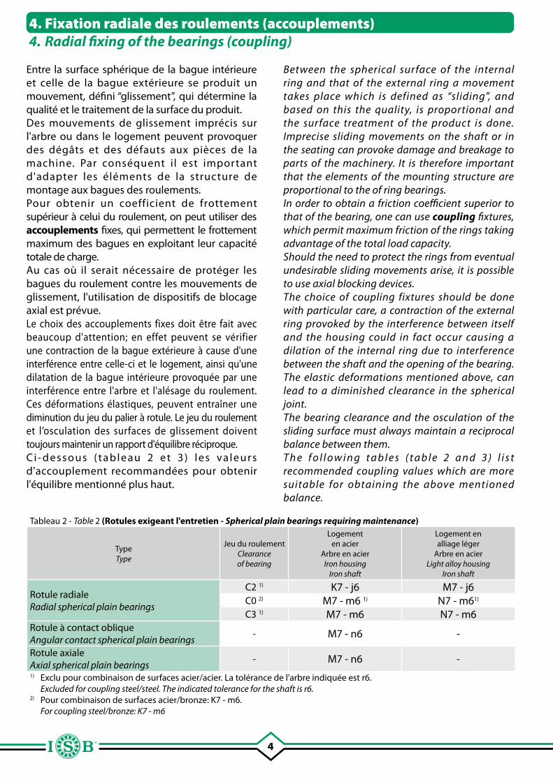
Entre la surface sphérique de la bague intérieure et celle de la bague extérieure se produit un mouvement, défini “glissement”, qui détermine la qualité et le traitement de la surface du produit. Des mouvements de glissement imprécis sur l'arbre ou dans le logement peuvent provoquer des dégâts et des défauts aux pièces de la machine. Par conséquent il est important d'adapter les éléments de la structure de montage aux bagues des roulements.Pour obtenir un coefficient de frottement supérieur à celui du roulement, on peut utiliser des accouplements fixes, qui permettent le frottement maximum des bagues en exploitant leur capacité totale de charge. Au cas où il serait nécessaire de protéger les bagues du roulement contre les mouvements de glissement, l'utilisation de dispositifs de blocage axial est prévue.Le choix des accouplements fixes doit être fait avec beaucoup d'attention; en effet peuvent se vérifier une contraction de la bague extérieure à cause d'une interférence entre celle-ci et le logement, ainsi qu'une dilatation de la bague intérieure provoquée par une interférence entre l'arbre et l'alésage du roulement. Ces déformations élastiques, peuvent entraîner une diminution du jeu du palier à rotule. Le jeu du roulement et l’osculation des surfaces de glissement doivent toujours maintenir un rapport d'équilibre réciproque. C i - dessous ( tableau 2 et 3 ) les va leurs d'accouplement recommandées pour obtenir l'équilibre mentionné plus haut.
4. Fixation radiale des roulements (accouplements)4. Radial fixing of the bearings (coupling)
Tableau 2 - Table 2 (Rotules exigeant l'entretien - Spherical plain bearings requiring maintenance)
TypeType
Jeu du roulementClearanceof bearing
Logementen acier
Arbre en acierIron housing
Iron shaft
Logement enalliage léger
Arbre en acierLight alloy housing
Iron shaft
Rotule radialeRadial spherical plain bearings
C2 1) K7 - j6 M7 - j6C0 2) M7 - m6 1) N7 - m61)
C3 1) M7 - m6 N7 - m6Rotule à contact obliqueAngular contact spherical plain bearings
- M7 - n6 -
Rotule axialeAxial spherical plain bearings
- M7 - n6 -1) Exclu pour combinaison de surfaces acier/acier. La tolérance de l'arbre indiquée est r6. Excluded for coupling steel/steel. The indicated tolerance for the shaft is r6.2) Pour combinaison de surfaces acier/bronze: K7 - m6. For coupling steel/bronze: K7 - m6
Between the spherical surface of the internal ring and that of the external ring a movement takes place which is defined as “sliding”, and based on this the quality, is proportional and the surface treatment of the product is done. Imprecise sliding movements on the shaft or in the seating can provoke damage and breakage to parts of the machinery. It is therefore important that the elements of the mounting structure are proportional to the of ring bearings.In order to obtain a friction coefficient superior to that of the bearing, one can use coupling fixtures, which permit maximum friction of the rings taking advantage of the total load capacity.Should the need to protect the rings from eventual undesirable sliding movements arise, it is possible to use axial blocking devices.The choice of coupling fixtures should be done with particular care, a contraction of the external ring provoked by the interference between itself and the housing could in fact occur causing a dilation of the internal ring due to interference between the shaft and the opening of the bearing. The elastic deformations mentioned above, can lead to a diminished clearance in the spherical joint.The bearing clearance and the osculation of the sliding surface must always maintain a reciprocal balance between them.T h e f o l l o w i n g t a b l e s ( t a b l e 2 a n d 3 ) l i s t recommended coupling values which are more suitable for obtaining the above mentioned balance.
5
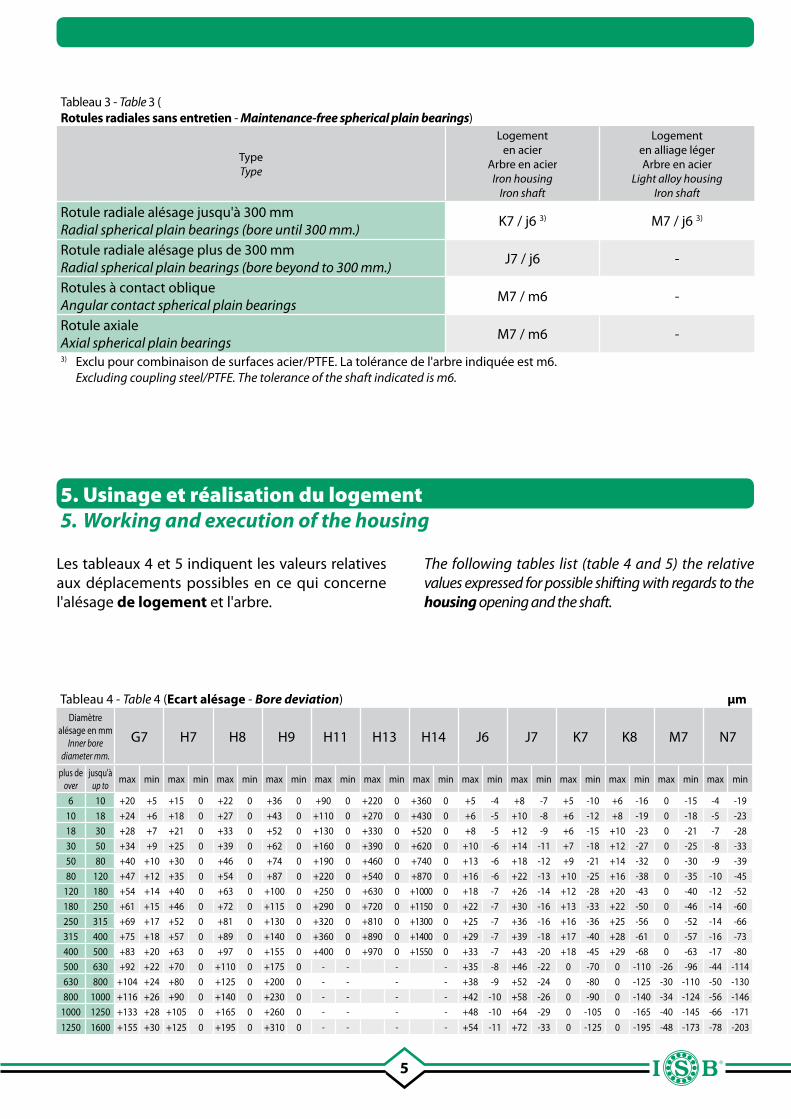
Tableau 3 - Table 3 (Rotules radiales sans entretien - Maintenance-free spherical plain bearings)
TypeType
Logementen acier
Arbre en acierIron housing
Iron shaft
Logementen alliage légerArbre en acier
Light alloy housingIron shaft
Rotule radiale alésage jusqu'à 300 mmRadial spherical plain bearings (bore until 300 mm.)
K7 / j6 3) M7 / j6 3)
Rotule radiale alésage plus de 300 mmRadial spherical plain bearings (bore beyond to 300 mm.)
J7 / j6 -
Rotules à contact obliqueAngular contact spherical plain bearings
M7 / m6 -
Rotule axialeAxial spherical plain bearings
M7 / m6 -
3) Exclu pour combinaison de surfaces acier/PTFE. La tolérance de l'arbre indiquée est m6. Excluding coupling steel/PTFE. The tolerance of the shaft indicated is m6.
5. Usinage et réalisation du logement5. Working and execution of the housing
Les tableaux 4 et 5 indiquent les valeurs relatives aux déplacements possibles en ce qui concerne l'alésage de logement et l'arbre.
Tableau 4 - Table 4 (Ecart alésage - Bore deviation) µmDiamètre
alésage en mmInner bore
diameter mm.
G7 H7 H8 H9 H11 H13 H14 J6 J7 K7 K8 M7 N7
plus deover
jusqu'àup to
max min max min max min max min max min max min max min max min max min max min max min max min max min
6 10 +20 +5 +15 0 +22 0 +36 0 +90 0 +220 0 +360 0 +5 -4 +8 -7 +5 -10 +6 -16 0 -15 -4 -19
10 18 +24 +6 +18 0 +27 0 +43 0 +110 0 +270 0 +430 0 +6 -5 +10 -8 +6 -12 +8 -19 0 -18 -5 -23
18 30 +28 +7 +21 0 +33 0 +52 0 +130 0 +330 0 +520 0 +8 -5 +12 -9 +6 -15 +10 -23 0 -21 -7 -28
30 50 +34 +9 +25 0 +39 0 +62 0 +160 0 +390 0 +620 0 +10 -6 +14 -11 +7 -18 +12 -27 0 -25 -8 -33
50 80 +40 +10 +30 0 +46 0 +74 0 +190 0 +460 0 +740 0 +13 -6 +18 -12 +9 -21 +14 -32 0 -30 -9 -39
80 120 +47 +12 +35 0 +54 0 +87 0 +220 0 +540 0 +870 0 +16 -6 +22 -13 +10 -25 +16 -38 0 -35 -10 -45
120 180 +54 +14 +40 0 +63 0 +100 0 +250 0 +630 0 +1000 0 +18 -7 +26 -14 +12 -28 +20 -43 0 -40 -12 -52
180 250 +61 +15 +46 0 +72 0 +115 0 +290 0 +720 0 +1150 0 +22 -7 +30 -16 +13 -33 +22 -50 0 -46 -14 -60
250 315 +69 +17 +52 0 +81 0 +130 0 +320 0 +810 0 +1300 0 +25 -7 +36 -16 +16 -36 +25 -56 0 -52 -14 -66
315 400 +75 +18 +57 0 +89 0 +140 0 +360 0 +890 0 +1400 0 +29 -7 +39 -18 +17 -40 +28 -61 0 -57 -16 -73
400 500 +83 +20 +63 0 +97 0 +155 0 +400 0 +970 0 +1550 0 +33 -7 +43 -20 +18 -45 +29 -68 0 -63 -17 -80
500 630 +92 +22 +70 0 +110 0 +175 0 - - - - +35 -8 +46 -22 0 -70 0 -110 -26 -96 -44 -114
630 800 +104 +24 +80 0 +125 0 +200 0 - - - - +38 -9 +52 -24 0 -80 0 -125 -30 -110 -50 -130
800 1000 +116 +26 +90 0 +140 0 +230 0 - - - - +42 -10 +58 -26 0 -90 0 -140 -34 -124 -56 -146
1000 1250 +133 +28 +105 0 +165 0 +260 0 - - - - +48 -10 +64 -29 0 -105 0 -165 -40 -145 -66 -171
1250 1600 +155 +30 +125 0 +195 0 +310 0 - - - - +54 -11 +72 -33 0 -125 0 -195 -48 -173 -78 -203
The following tables list (table 4 and 5) the relative values expressed for possible shifting with regards to the housing opening and the shaft.
6
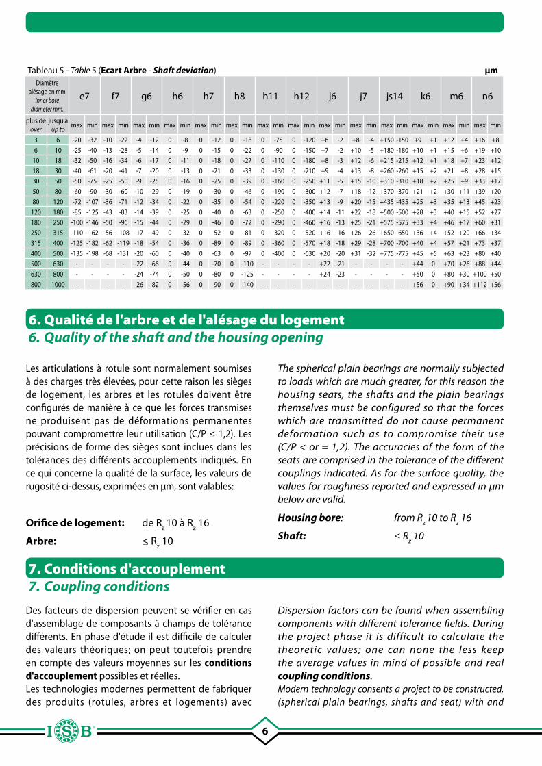
Les articulations à rotule sont normalement soumises à des charges très élevées, pour cette raison les sièges de logement, les arbres et les rotules doivent être configurés de manière à ce que les forces transmises ne produisent pas de déformations permanentes pouvant compromettre leur utilisation (C/P ≤ 1,2). Les précisions de forme des sièges sont inclues dans les tolérances des différents accouplements indiqués. En ce qui concerne la qualité de la surface, les valeurs de rugosité ci-dessus, exprimées en µm, sont valables:
Orifice de logement: de Rz 10 à R
z 16
Arbre: ≤ Rz 10
6. Qualité de l'arbre et de l'alésage du logement6. Quality of the shaft and the housing opening
Des facteurs de dispersion peuvent se vérifier en cas d'assemblage de composants à champs de tolérance différents. En phase d'étude il est difficile de calculer des valeurs théoriques; on peut toutefois prendre en compte des valeurs moyennes sur les conditions d'accouplement possibles et réelles.Les technologies modernes permettent de fabriquer des produits (rotules, arbres et logements) avec
7. Conditions d'accouplement7. Coupling conditions
Tableau 5 - Table 5 (Ecart Arbre - Shaft deviation) µmDiamètre
alésage en mmInner bore
diameter mm.
e7 f7 g6 h6 h7 h8 h11 h12 j6 j7 js14 k6 m6 n6
plus deover
jusqu'àup to
max min max min max min max min max min max min max min max min max min max min max min max min max min max min
3 6 -20 -32 -10 -22 -4 -12 0 -8 0 -12 0 -18 0 -75 0 -120 +6 -2 +8 -4 +150 -150 +9 +1 +12 +4 +16 +8
6 10 -25 -40 -13 -28 -5 -14 0 -9 0 -15 0 -22 0 -90 0 -150 +7 -2 +10 -5 +180 -180 +10 +1 +15 +6 +19 +10
10 18 -32 -50 -16 -34 -6 -17 0 -11 0 -18 0 -27 0 -110 0 -180 +8 -3 +12 -6 +215 -215 +12 +1 +18 +7 +23 +12
18 30 -40 -61 -20 -41 -7 -20 0 -13 0 -21 0 -33 0 -130 0 -210 +9 -4 +13 -8 +260 -260 +15 +2 +21 +8 +28 +15
30 50 -50 -75 -25 -50 -9 -25 0 -16 0 -25 0 -39 0 -160 0 -250 +11 -5 +15 -10 +310 -310 +18 +2 +25 +9 +33 +17
50 80 -60 -90 -30 -60 -10 -29 0 -19 0 -30 0 -46 0 -190 0 -300 +12 -7 +18 -12 +370 -370 +21 +2 +30 +11 +39 +20
80 120 -72 -107 -36 -71 -12 -34 0 -22 0 -35 0 -54 0 -220 0 -350 +13 -9 +20 -15 +435 -435 +25 +3 +35 +13 +45 +23
120 180 -85 -125 -43 -83 -14 -39 0 -25 0 -40 0 -63 0 -250 0 -400 +14 -11 +22 -18 +500 -500 +28 +3 +40 +15 +52 +27
180 250 -100 -146 -50 -96 -15 -44 0 -29 0 -46 0 -72 0 -290 0 -460 +16 -13 +25 -21 +575 -575 +33 +4 +46 +17 +60 +31
250 315 -110 -162 -56 -108 -17 -49 0 -32 0 -52 0 -81 0 -320 0 -520 +16 -16 +26 -26 +650 -650 +36 +4 +52 +20 +66 +34
315 400 -125 -182 -62 -119 -18 -54 0 -36 0 -89 0 -89 0 -360 0 -570 +18 -18 +29 -28 +700 -700 +40 +4 +57 +21 +73 +37
400 500 -135 -198 -68 -131 -20 -60 0 -40 0 -63 0 -97 0 -400 0 -630 +20 -20 +31 -32 +775 -775 +45 +5 +63 +23 +80 +40
500 630 - - - - -22 -66 0 -44 0 -70 0 -110 - - - - +22 -21 - - - - +44 0 +70 +26 +88 +44
630 800 - - - - -24 -74 0 -50 0 -80 0 -125 - - - - +24 -23 - - - - +50 0 +80 +30 +100 +50
800 1000 - - - - -26 -82 0 -56 0 -90 0 -140 - - - - - - - - - - +56 0 +90 +34 +112 +56
The spherical plain bearings are normally subjected to loads which are much greater, for this reason the housing seats, the shafts and the plain bearings themselves must be configured so that the forces which are transmitted do not cause permanent deformation such as to compromise their use (C/P < or = 1,2). The accuracies of the form of the seats are comprised in the tolerance of the different couplings indicated. As for the surface quality, the values for roughness reported and expressed in µm below are valid.
Housing bore: from Rz 10 to R
z 16
Shaft: ≤ Rz 10
Dispersion factors can be found when assembling components with different tolerance fields. During the project phase it is difficult to calculate the theoretic values; one can none the less keep the average values in mind of possible and real coupling conditions. Modern technology consents a project to be constructed, (spherical plain bearings, shafts and seat) with and
7
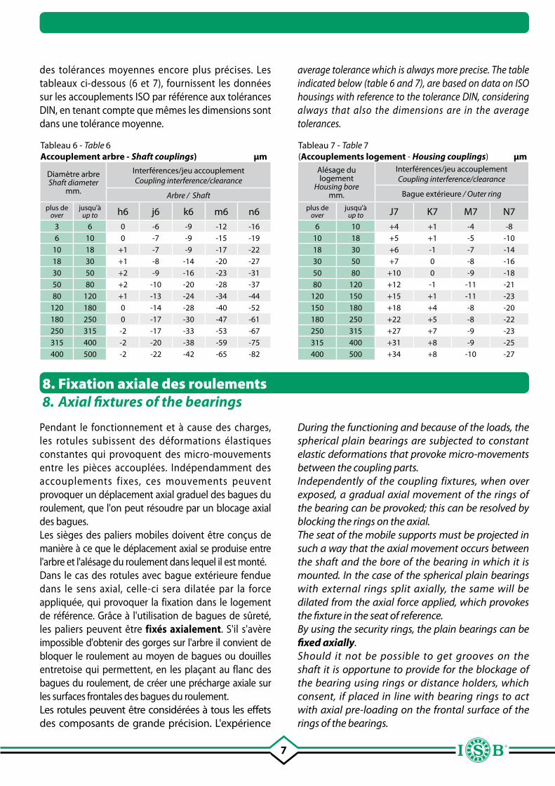
Tableau 6 - Table 6Accouplement arbre - Shaft couplings) µm
Diamètre arbreShaft diameter
mm.
Interférences/jeu accouplementCoupling interference/clearance
Arbre / Shaft
plus deover
jusqu'àup to h6 j6 k6 m6 n6
3 6 0 -6 -9 -12 -166 10 0 -7 -9 -15 -19
10 18 +1 -7 -9 -17 -2218 30 +1 -8 -14 -20 -2730 50 +2 -9 -16 -23 -3150 80 +2 -10 -20 -28 -3780 120 +1 -13 -24 -34 -44
120 180 0 -14 -28 -40 -52180 250 0 -17 -30 -47 -61250 315 -2 -17 -33 -53 -67315 400 -2 -20 -38 -59 -75400 500 -2 -22 -42 -65 -82
Tableau 7 - Table 7 (Accouplements logement - Housing couplings) µm
Alésage du logement
Housing boremm.
Interférences/jeu accouplementCoupling interference/clearance
Bague extérieure / Outer ring
plus deover
jusqu'àup to J7 K7 M7 N7
6 10 +4 +1 -4 -810 18 +5 +1 -5 -1018 30 +6 -1 -7 -1430 50 +7 0 -8 -1650 80 +10 0 -9 -1880 120 +12 -1 -11 -21
120 150 +15 +1 -11 -23150 180 +18 +4 -8 -20180 250 +22 +5 -8 -22250 315 +27 +7 -9 -23315 400 +31 +8 -9 -25400 500 +34 +8 -10 -27
8. Fixation axiale des roulements8. Axial fixtures of the bearings
des tolérances moyennes encore plus précises. Les tableaux ci-dessous (6 et 7), fournissent les données sur les accouplements ISO par référence aux tolérances DIN, en tenant compte que mêmes les dimensions sont dans une tolérance moyenne.
Pendant le fonctionnement et à cause des charges, les rotules subissent des déformations élastiques constantes qui provoquent des micro-mouvements entre les pièces accouplées. Indépendamment des accouplements fixes, ces mouvements peuvent provoquer un déplacement axial graduel des bagues du roulement, que l'on peut résoudre par un blocage axial des bagues.Les sièges des paliers mobiles doivent être conçus de manière à ce que le déplacement axial se produise entre l'arbre et l'alésage du roulement dans lequel il est monté.Dans le cas des rotules avec bague extérieure fendue dans le sens axial, celle-ci sera dilatée par la force appliquée, qui provoquer la fixation dans le logement de référence. Grâce à l'utilisation de bagues de sûreté, les paliers peuvent être fixés axialement. S'il s'avère impossible d'obtenir des gorges sur l'arbre il convient de bloquer le roulement au moyen de bagues ou douilles entretoise qui permettent, en les plaçant au flanc des bagues du roulement, de créer une précharge axiale sur les surfaces frontales des bagues du roulement.Les rotules peuvent être considérées à tous les effets des composants de grande précision. L'expérience
average tolerance which is always more precise. The table indicated below (table 6 and 7), are based on data on ISO housings with reference to the tolerance DIN, considering always that also the dimensions are in the average tolerances.
During the functioning and because of the loads, the spherical plain bearings are subjected to constant elastic deformations that provoke micro-movements between the coupling parts.Independently of the coupling fixtures, when over exposed, a gradual axial movement of the rings of the bearing can be provoked; this can be resolved by blocking the rings on the axial. The seat of the mobile supports must be projected in such a way that the axial movement occurs between the shaft and the bore of the bearing in which it is mounted. In the case of the spherical plain bearings with external rings split axially, the same will be dilated from the axial force applied, which provokes the fixture in the seat of reference.By using the security rings, the plain bearings can be fixed axially. Should it not be possible to get grooves on the shaft it is opportune to provide for the blockage of the bearing using rings or distance holders, which consent, if placed in line with bearing rings to act with axial pre-loading on the frontal surface of the rings of the bearings.
8
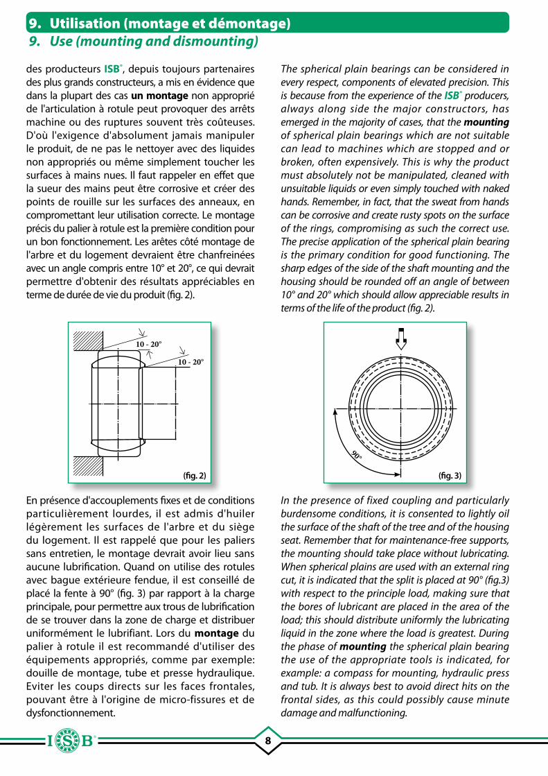
des producteurs ISB®, depuis toujours partenaires des plus grands constructeurs, a mis en évidence que dans la plupart des cas un montage non approprié de l'articulation à rotule peut provoquer des arrêts machine ou des ruptures souvent très coûteuses. D'où l'exigence d'absolument jamais manipuler le produit, de ne pas le nettoyer avec des liquides non appropriés ou même simplement toucher les surfaces à mains nues. Il faut rappeler en effet que la sueur des mains peut être corrosive et créer des points de rouille sur les surfaces des anneaux, en compromettant leur utilisation correcte. Le montage précis du palier à rotule est la première condition pour un bon fonctionnement. Les arêtes côté montage de l'arbre et du logement devraient être chanfreinées avec un angle compris entre 10° et 20°, ce qui devrait permettre d'obtenir des résultats appréciables en terme de durée de vie du produit (fig. 2).
9. Utilisation (montage et démontage)9. Use (mounting and dismounting)
(fig. 2) (fig. 3)
En présence d'accouplements fixes et de conditions particulièrement lourdes, il est admis d'huiler légèrement les surfaces de l'arbre et du siège du logement. Il est rappelé que pour les paliers sans entretien, le montage devrait avoir lieu sans aucune lubrification. Quand on utilise des rotules avec bague extérieure fendue, il est conseillé de placé la fente à 90° (fig. 3) par rapport à la charge principale, pour permettre aux trous de lubrification de se trouver dans la zone de charge et distribuer uniformément le lubrifiant. Lors du montage du palier à rotule il est recommandé d'utiliser des équipements appropriés, comme par exemple: douille de montage, tube et presse hydraulique. Eviter les coups directs sur les faces frontales, pouvant être à l'origine de micro-fissures et de dysfonctionnement.
90°
10 - 20°
10 - 20°
The spherical plain bearings can be considered in every respect, components of elevated precision. This is because from the experience of the ISB® producers, always along side the major constructors, has emerged in the majority of cases, that the mounting of spherical plain bearings which are not suitable can lead to machines which are stopped and or broken, often expensively. This is why the product must absolutely not be manipulated, cleaned with unsuitable liquids or even simply touched with naked hands. Remember, in fact, that the sweat from hands can be corrosive and create rusty spots on the surface of the rings, compromising as such the correct use. The precise application of the spherical plain bearing is the primary condition for good functioning. The sharp edges of the side of the shaft mounting and the housing should be rounded off an angle of between 10° and 20° which should allow appreciable results in terms of the life of the product (fig. 2).
In the presence of fixed coupling and particularly burdensome conditions, it is consented to lightly oil the surface of the shaft of the tree and of the housing seat. Remember that for maintenance-free supports, the mounting should take place without lubricating. When spherical plains are used with an external ring cut, it is indicated that the split is placed at 90° (fig.3) with respect to the principle load, making sure that the bores of lubricant are placed in the area of the load; this should distribute uniformly the lubricating liquid in the zone where the load is greatest. During the phase of mounting the spherical plain bearing the use of the appropriate tools is indicated, for example: a compass for mounting, hydraulic press and tub. It is always best to avoid direct hits on the frontal sides, as this could possibly cause minute damage and malfunctioning.
9
S'il n'est pas possible d'utiliser des outils ordinaires, comme ceux indiqués ci-dessus, le montage peut être fait à travers la technique du chauffage et du refroidissement, mais il est toujours conseillé de s'adresser aux producteurs ISB® car une mauvaise application de ces techniques pourrait compromettre définitivement l'utilisation du palier à rotule.La phase de démontage du palier à rotule, peut s'avérer extrêmement délicat, car grâce à la conformation du produit en agissant sur la bague à démonter, la résistance due à l'accouplement de l'autre bague, créé justement un effet de blocage. Pour remédier à ce problème, il conviendrait, dès la phase d'études, de prévoir sur le siège des trous filetés pour les vis de démontage ou des fraisages sur l'arbre pour l'utilisation d'outils de démontage.
10. Protection du logement10. Protection of the seat
Pour obtenir un fonctionnement et une usure correcte des rotules, il est fondamental d'utiliser une protection contre les contaminants extérieurs (poussière, humidité etc…), en appliquant un joint d'étanchéité approprié.Il existe plusieurs critères de sélection du joint: espace, mouvement radial, angle de déversement du roulement, conditions ambiantes etc.Une solution d'étanchéité simple et efficace peut être apportée par la couche de graisse utilisée pour la lubrification. En prévoyant un entretien constant, ce type d'étanchéité donne d'excellents résultats dans des conditions particulières de fonctionnement.Dans le cas d'applications internes, le joint ordinaire 2RS constitué de polyuréthane, monté des deux côtés, suffit. Il existe des "joints spéciaux" adaptés aux applications pour les milieux avec conditions extrêmes (jusqu'à +200 °C). A l'extérieur on peut utiliser des joints simples en polyuréthane élastomère, particulièrement indiqués pour les rotules radiales. On peut aussi utiliser des bagues type V, particulièrement indiquées en présence de mouvements basculant importants, ou encore des bagues en plastique à armature en acier et des joints à lèvre anti-poussière.
Should it not be possible to use the ordinary tools, it is possible to mount using heating and cooling techniques, but it is always advisable to seek assistance from ISB® producers because the incorrect application of these techniques could compromise definitively the use of the spherical plain bearing.The dismounting phase of the spherical plain bearing can be extremely delicate thanks to the conformation of the product acting on the ring to dismount, the resistance due to the coupling of the other ring, creates a blocking effect. To overcome this problem, it would be already indicated, in the project phase to foresee on the seat of the bores threads for screws for dismounting or profiling on the shaft to use instruments for dismounting.
In order to obtain a good functioning and correct wear of the spherical plain bearings it is fundamental to use protection from eventual external contaminating agents (dust, humidity etc…) applying an adequate amount. Different criteria exist for the choice of protection: s p a ce, ra d i a l m ove m e n t , b o u n c i n g a n g l e, environmental conditions etc.A possible setting which is ver y simple and effective could be given from the layer of grease used for lubrication. With constant maintenance, this type of setting gives excellent results in particular functioning conditions. In the case of internal applications, the common hold 2RS, consisting of polyurethane, mounted bi lateral ly, is suff icient. There are “special holds” which are adapted for applications in an ambient with extreme conditions (up to +200 °C). Externally it is possible to use a simple hold in elastic polyurethane, particularly indicated for the spherical radial bearings. It is also possible to use V rings, particularly indicated in the presence of significant bouncing movements; rings in plastic with steel armature and rings with anti-dust lips are supplementary.
10
En général, la lubrification des roulements est sans aucun doute importante, car elle porte à une réduction du frottement, protège contre les agents corrosifs et crée une séparation entre les surfaces de glissement. Le choix du lubrifiant à utiliser dépend de plusieurs facteurs, comme par exemple: charge, direction de la charge, angle d'oscillation, vitesse et conditions ambiantes. Pour les applications standard, il est conseillé d'utiliser les lubrifiants ordinaires que l'on trouve dans le commerce, résistants à la pression, à base de savon de lithium, lubrifiants solides et additifs EP. Ces additifs solides, mélangés au lubrifiant, permettent une séparation parfaite des surfaces de glissement même en cas de haute pression superficielle, en évitant ainsi la rupture du roulement. Les lubrifiant avec environ 3% de MoS
2, ou les additifs
solides contenant du calcium et du phosphate de zinc combinés sont appropriés.Le lubrifiant particulièrement indiqué pour les rotules avec combinaison acier/bronze, doit être à base de savon de lithium, anti-corrosion, hydrofuge et de consistance normale, ne contenant pas d'additifs de MoS
2 ou d'autres lubrifiants solides.
La phase initiale de la lubrification est très importante; il faut faire attention aux conditions techniques dans lesquelles on travaille, pour obtenir une détérioration uniforme et un rendement optimal du palier à rotule dans le temps. Pour les rotules lisses à combinaison acier/acier, la lubrification doit être régulière; cette action permet d'éliminer les résidus du lubrifiant usagé qui est remplacé par du lubrifiant frais, ainsi que les résidus d'usure et les impuretés . La fréquence et les intervalles de lubrification doivent être évalués attentivement, à partir de plusieurs facteurs, tels que: charge, vitesse, conditions d'utilisation etc… étant donné qu'une lubrification trop fréquente peut porter aussi à un mauvais fonctionnement de la rotule en réduisant sa durée.Les rotules sans entretien ne doivent pas être lubrifiées, raison pour laquelle elles sont fournies sans dispositif de lubrification. L'action de glissement est facilitée pendant la période de rodage, quand le transfert de particules de PTFE, de la bague extérieure à la surface de glissement de la bague intérieure, sert à compenser les rugosités éventuelles qui pourraient être présentes sur la
11. Lubrification11. Lubrication
In a general sense, the lubrication of the bearings is particularly important, because it leads to a reduction in friction, protects from corrosive external agents, and acts as a separator from the sliding surface.The choice of lubricant to use is determined by different factors, for example: load, direction of the load, angle of oscillation, speed and ambient condition.For standard applications, common lubricants that can be found on the commercial market that are anticorrosive, resistant to pressure and based on lithium soap with solid lubricants and EP added are indicated.These solid additives, mixed with the lubricant, allow the perfect separation between the sliding surfaces, even in cases of elevated surface pressure, avoiding, in addition, breakage of the bearing. Lubricants with about 3% of MoS
2 are suitable,
or solid additives containing calcium and zinc phosphate combined.For spherical plain bearings with iron/bronze coupling, lubricants with a base of lithium soap, anticorrosive, hydro repellant and of normal consistency, but without MoS
2 or other solid
lubricants are particularly indicated. The initial phase of lubrication is very important; one must pay a lot of attention to the technical conditions in which one is working in order to obtain a uniform consumption and an optimal yield from a spherical plain bearing over time.For spherical plain bearings with steel/steel couplings, a regular lubrication is required; through this activity, residual used lubricant is eliminated and substituted with new lubricant, abrasive residue impurities are expulsed. The frequency as well as the intervals of lubrication must be evaluated carefully confronting different factors, such as: load, speed, conditions of use etc. because a lubrication which is too frequent can lead to malfunctioning for the spherical plain bearing reducing its lifetime.Maintenance-free spherical plain bearings must not be lubricated; which is why they are not supplied with relubrication devices.The running process is facilitated during the running period when the PTFE par ticles are transferred from the external ring to the surface of the internal ring, this smoothes the roughness that
11
surface de la bague intérieure. Si les rotules sans entretien sont lubrifiées, l'effet de transfert et lissage vient à manquer, compte tenu des faibles capacité adhésives des particules de PTFE sur les surfaces lubrifiées.Toutes les notions énoncées ci-dessus sont valables même pour les embouts.
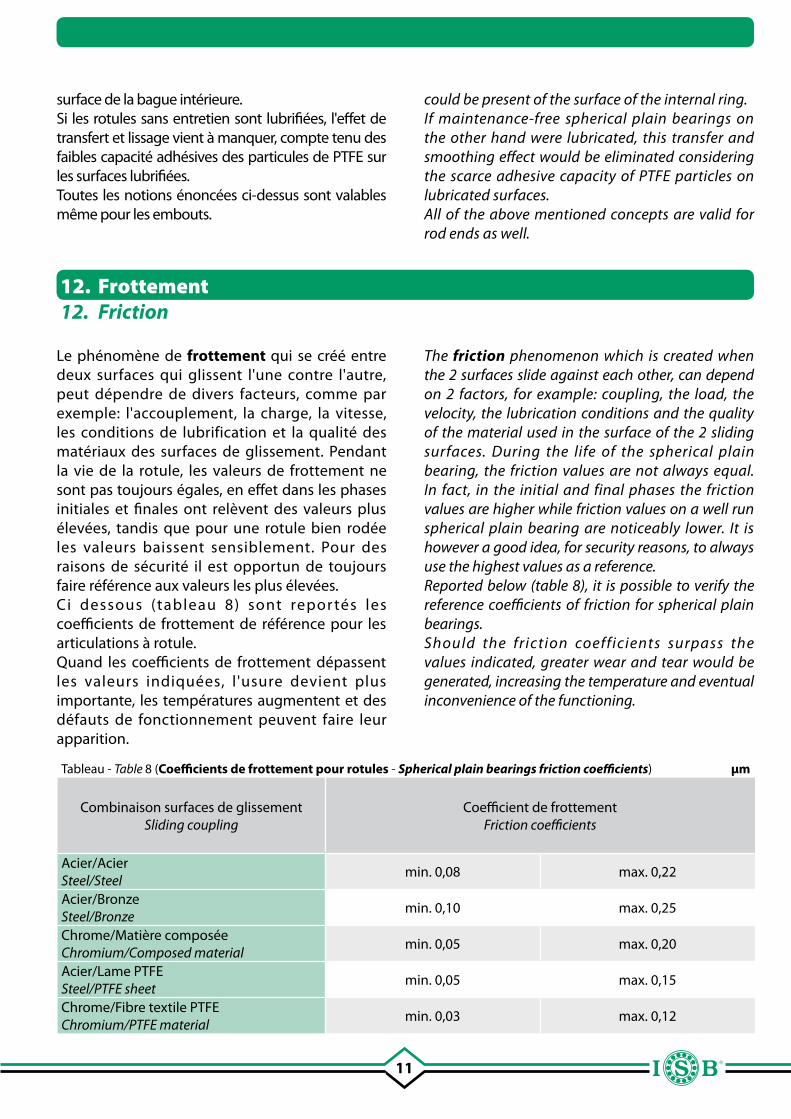
Tableau - Table 8 (Coefficients de frottement pour rotules - Spherical plain bearings friction coefficients) µm
Combinaison surfaces de glissementSliding coupling
Coefficient de frottement Friction coefficients
Acier/AcierSteel/Steel
min. 0,08 max. 0,22
Acier/BronzeSteel/Bronze
min. 0,10 max. 0,25
Chrome/Matière composéeChromium/Composed material
min. 0,05 max. 0,20
Acier/Lame PTFESteel/PTFE sheet
min. 0,05 max. 0,15
Chrome/Fibre textile PTFEChromium/PTFE material
min. 0,03 max. 0,12
Le phénomène de frottement qui se créé entre deux surfaces qui glissent l'une contre l'autre, peut dépendre de divers facteurs, comme par exemple: l'accouplement, la charge, la vitesse, les conditions de lubrification et la qualité des matériaux des surfaces de glissement. Pendant la vie de la rotule, les valeurs de frottement ne sont pas toujours égales, en effet dans les phases initiales et finales ont relèvent des valeurs plus élevées, tandis que pour une rotule bien rodée les valeurs baissent sensiblement. Pour des raisons de sécurité il est opportun de toujours faire référence aux valeurs les plus élevées.Ci dessous (tableau 8) sont repor tés les coefficients de frottement de référence pour les articulations à rotule.Quand les coefficients de frottement dépassent les valeurs indiquées, l 'usure devient plus importante, les températures augmentent et des défauts de fonctionnement peuvent faire leur apparition.
12. Frottement12. Friction
could be present of the surface of the internal ring.If maintenance-free spherical plain bearings on the other hand were lubricated, this transfer and smoothing effect would be eliminated considering the scarce adhesive capacity of PTFE particles on lubricated surfaces.All of the above mentioned concepts are valid for rod ends as well.
The friction phenomenon which is created when the 2 surfaces slide against each other, can depend on 2 factors, for example: coupling, the load, the velocity, the lubrication conditions and the quality of the material used in the surface of the 2 sliding surfaces. During the life of the spherical plain bearing, the friction values are not always equal. In fact, in the initial and final phases the friction values are higher while friction values on a well run spherical plain bearing are noticeably lower. It is however a good idea, for security reasons, to always use the highest values as a reference.Reported below (table 8), it is possible to verify the reference coefficients of friction for spherical plain bearings.Should the friction coefficients surpass the values indicated, greater wear and tear would be generated, increasing the temperature and eventual inconvenience of the functioning.
12
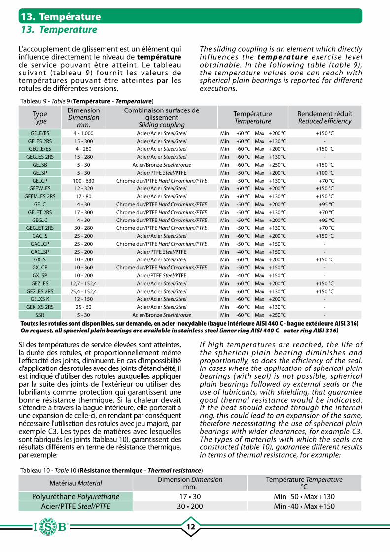
L'accouplement de glissement est un élément qui influence directement le niveau de température de service pouvant être atteint. Le tableau suivant (tableau 9) fournit les valeurs de températures pouvant être atteintes par les rotules de différentes versions.
Tableau 10 - Table 10 (Résistance thermique - Thermal resistance)
Matériau Material Dimension Dimensionmm.
Température Temperature°C
Polyuréthane Polyurethane 17 • 30 Min -50 • Max +130Acier/PTFE Steel/PTFE 30 • 200 Min -40 • Max +150
Tableau 9 - Table 9 (Température - Temperature)
Type Type
Dimension Dimension
mm.
Combinaison surfaces de glissement
Sliding coupling
Température Temperature
Rendement réduit Reduced efficiency
GE..E/ES 4 - 1.000 Acier/Acier Steel/Steel Min -60 °C Max +200 °C +150 °C
GE..ES 2RS 15 - 300 Acier/Acier Steel/Steel Min -60 °C Max +130 °C -
GEG..E/ES 4 - 280 Acier/Acier Steel/Steel Min -60 °C Max +200 °C +150 °C
GEG..ES 2RS 15 - 280 Acier/Acier Steel/Steel Min -60 °C Max +130 °C -
GE..SB 5 - 30 Acier/Bronze Steel/Bronze Min -60 °C Max +250 °C +150 °C
GE..SP 5 - 30 Acier/PTFE Steel/PTFE Min -50 °C Max +200 °C +100 °C
GE..CP 100 - 630 Chrome dur/PTFE Hard Chromium/PTFE Min -50 °C Max +130 °C +70 °C
GEEW..ES 12 - 320 Acier/Acier Steel/Steel Min -60 °C Max +200 °C +150 °C
GEEM..ES 2RS 17 - 80 Acier/Acier Steel/Steel Min -60 °C Max +130 °C +150 °C
GE..C 4 - 30 Chrome dur/PTFE Hard Chromium/PTFE Min -50 °C Max +200 °C +95 °C
GE..ET 2RS 17 - 300 Chrome dur/PTFE Hard Chromium/PTFE Min -50 °C Max +130 °C +70 °C
GEG..C 4 - 30 Chrome dur/PTFE Hard Chromium/PTFE Min -50 °C Max +200 °C +95 °C
GEG..ET 2RS 30 - 280 Chrome dur/PTFE Hard Chromium/PTFE Min -50 °C Max +130 °C +70 °C
GAC..S 25 - 200 Acier/Acier Steel/Steel Min -60 °C Max +200 °C +150 °C
GAC..CP 25 - 200 Chrome dur/PTFE Hard Chromium/PTFE Min -50 °C Max +150 °C -
GAC..SP 25 - 200 Acier/PTFE Steel/PTFE Min -40 °C Max +150 °C -
GX..S 10 - 200 Acier/Acier Steel/Steel Min -60 °C Max +200 °C +150 °C
GX..CP 10 - 360 Chrome dur/PTFE Hard Chromium/PTFE Min -50 °C Max +150 °C -
GX..SP 10 - 200 Acier/PTFE Steel/PTFE Min -40 °C Max +150 °C -
GEZ..ES 12,7 - 152,4 Acier/Acier Steel/Steel Min -60 °C Max +200 °C +150 °C
GEZ..ES 2RS 25,4 - 152,4 Acier/Acier Steel/Steel Min -60 °C Max +130 °C +150 °C
GE..XS K 12 - 150 Acier/Acier Steel/Steel Min -60 °C Max +200 °C -
GEK..XS 2RS 25 - 60 Acier/Acier Steel/Steel Min -60 °C Max +130 °C -
SSR 5 - 30 Acier/Bronze Steel/Bronze Min -60 °C Max +250 °C -
Toutes les rotules sont disponibles, sur demande, en acier inoxydable (bague intérieure AISI 440 C - bague extérieure AISI 316)On request, all spherical plain bearings are available in stainless steel (inner ring AISI 440 C - outer ring AISI 316)
Si des températures de service élevées sont atteintes, la durée des rotules, et proportionnellement même l'efficacité des joints, diminuent. En cas d'impossibilité d'application des rotules avec des joints d'étanchéité, il est indiqué d'utiliser des rotules auxquelles appliquer par la suite des joints de l'extérieur ou utiliser des lubrifiants comme protection qui garantissent une bonne résistance thermique. Si la chaleur devait s'étendre à travers la bague intérieure, elle porterait à une expansion de celle-ci, en rendant par conséquent nécessaire l'utilisation des rotules avec jeu majoré, par exemple C3. Les types de matières avec lesquelles sont fabriqués les joints (tableau 10), garantissent des résultats différents en terme de résistance thermique, par exemple:
13. Température13. Temperature
The sliding coupling is an element which directly i n f l u e n ce s t h e te m p e ra t u r e e xe rc i s e l e ve l obtainable. In the following table (table 9), the temperature values one can reach with spherical plain bearings is reported for different executions.
If high temperatures are reached, the life of the spherical plain bearing diminishes and proportionally, so does the efficiency of the seal. In cases where the application of spherical plain bearings (with seal) is not possible, spherical plain bearings followed by external seals or the use of lubricants, with shielding, that guarantee good thermal resistance would be indicated. If the heat should extend through the internal ring, this could lead to an expansion of the same, therefore necessitating the use of spherical plain bearings with wider clearances, for example C3. The types of materials with which the seals are constructed (table 10), guarantee different results in terms of thermal resistance, for example:
13
La charge appliquée, est certainement l'un des principaux éléments qui influencent la durée et le choix d'un palier à rotule. Ensemble à la charge il faut toujours prendre en compte d'autres éléments, comme le mouvement, la durée et l'entretien, si prévu. Le choix de la dimension du roulement varie en fonction de la charge, de la direction et de l'accouplement de glissement. Sur la base de tous les éléments ci-dessus, on peut faire le choix approprié du type de palier à rotule à utiliser. Après avoir déterminé la valeur de la charge, on peut déterminer la durée théorique, en sachant que la charge agit dans le sens radial pour les rotules radiales et dans le sens axial pour les rotules axiales et que pendant le fonctionnement, la direction et la grandeur de la charge demeurent inchangées. Il se peut que les rotules soient sollicitées simultanément dans la direction radiale et axiale, il faut par conséquent indiquer une valeur P dans la formule de la durée, qui sera calculée de la manière suivante:
P = “X” • Fr
P = “Y” • Fa
Où,
• P: charge dynamique équivalente kN
• Fr: charge radiale kN
• Fa: charge axiale kN
• “X”: facteur de support charge axiale, par référence aux rotules radiales
• “Y”: facteur de support charge radiale, par référence aux rotules axiales
14. Charge14. Load
15. Charge dynamique C15. Dynamic load C
On défini “charge dynamique C” la charge appliquée sur les rotules ou les embouts soumis à des contraintes dynamiques, en présence de mouvements oscillants, de déversement ou de rotation. L'action de la charge sera dans le sens radial pour les rotules radiales et à contact oblique et pour les embouts, mais purement axial et centré pour les rotules axiales. Chaque mouvement sur le surface de glissement produit une usure et de la fatigue, dont il faut tenir compte. Les indications des coefficients de charge sont souvent associées au producteur et par conséquent il deviendrait difficile d'effectuer des comparaisons avec d'autres produits de la même catégorie.
The applicable load is surely one of the principle elements which influence the duration and the choice of the spherical plain bearing. Together with the load, other elements must be considered, such as the movement, the duration and the maintenance if foreseen. The choice of the dimension of the bearing varies when the load as well as the direction and sliding coupling vary. Based on all of the above mentioned elements, the best choice can be carried out on which spherical plain bearing to use. Once the load value is determined, determine the theoretic duration, knowing that the load acts in radial sense for radial spherical plain bearings and in axial sense for axial spherical plain bearings and that during the functioning, the direction and entity remain unvaried.I t i s p o s s i b l e t h e b e a r i n g s a r e s o l i c i t e d contemporaneously in both radial and axial direction, it is therefore a good idea to indicate P value in the duration formula which will be calculated as follows:
P = “X” • Fr
P = “Y” • Fa
considering,
• P: dynamic load kN equivalent
• Fr: radial load kN
• Fa: axial load kN
• “X”: axial load movement factor referred to radial spherical plain bearings
• “Y”: radial load movement factor referring to axial spherical plain bearings
The “C dynamic load” is defined the load applied on spherical plain bearings or heads subjected to dynamic solicitations, in the presence as such of oscillating movements of bouncing or rotation. The action of the load will be in a radial sense for radial spherical plain bearings and at angular contact for the rod ends, while purely axial and centered for axial spherical plain bearings. Every movement on the sliding surface generates wear and tear and this should be kept in mind. The indications of the load coefficients are often tied to the producer and as such could become difficult to make comparisons with other products of the same category.
14
17. Mouvements des rotules17. Movements of the spherical plain bearings
On défini “charge statique C0” la charge maximale appliquée sur les rotules ou les embouts en présence de:• petits mouvements d'ajustement • charges supplémentaires dues au chocs• situations statiques. A température ambiante la charge statique ne doit pas influer sur le fonctionnement du produit, de manière à ne pas provoquer de ruptures ou de dégâts sur les surfaces de glissement. Pour obtenir une bonne durée de service il est fondamental que la charge soit adaptée aux conditions de fonctionnement. La charge statique détermine la pression superficielle sur la rotule. Pour déterminer cette pression spécifique on peut adopter la formule suivante:
p = K • PC
où:• p: pression N/mm2
• K: valeur charge spécifique N/mm2
• P: charge équivalente sur le roulement kN• C: charge dynamique kN
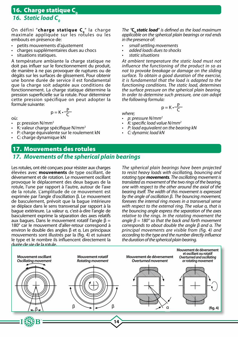
Les rotules, ont été conçues pour résister aux charges élevées avec mouvements de type oscillant, de déversement et de rotation. Le mouvement oscillant provoque le déplacement des deux bagues de la rotule, l'une par rapport à l'autre, autour de l'axe de la rotule. L'amplitude de ce mouvement est exprimée par l'angle d'oscillation β. Le mouvement de basculement, prévoit que la bague intérieure se déplace dans le sens transversal par rapport à la bague extérieure. La valeur α, c'est-à-dire l’angle de basculement exprime la séparation des axes relatifs aux bagues. Dans le mouvement rotatif l’angle β = 180° car le mouvement d'aller-retour correspond à environ le double des angles β et α. Les principaux mouvements sont illustrés par la (fig. 4) et suivant le type et le nombre ils influencent directement la durée de vie de la rotule.
(fig. 4)
Mouvement oscillantOscillating movement
Mouvement rotatifRotating movement
Mouvement de déversementOverturned movement
Mouvement de déversement et oscillant ou rotatif
Overturned and oscillatingor rotating movement
16. Charge statique C0
16. Static load C0
ββ β α
The “C0 static load” is defined as the load maximum applicable on the spherical plain bearings or rod ends in the presence of:• small settling movements• added loads dues to shocks• static situationsAt ambient temperature the static load must not influence the functioning of the product in so as not to provoke breakage or damage on the sliding surface. To obtain a good duration of the exercise, it is fundamental that the load is adapted to the functioning conditions. The static load, determines the surface pressure on the spherical plain bearing. In order to determine such pressure, one can adopt the following formula:
p = K • PC
where;• p: pressure N/mm2
• K: specific load value N/mm2
• P: load equivalent on the bearing kN• C: dynamic load kN
The spherical plain bearings have been projected to resist heavy loads with oscillating, bouncing and rotating type movements. The oscillating movement is translated as movement of the two rings of the bearing, one with respect to the other around the axial of the bearing itself. The width of this movement is expressed by the angle of oscillation β. The bouncing movement, foresees the internal ring moves in a transversal sense with respect to the external ring. The value α, that is the bouncing angle express the separation of the axes relative to the rings. In the rotating movement the angle β = 180° so that the back and forth movement corresponds to about double the angle β and α. The principal movements are visible from (fig. 4) and according to the type and the number directly influence the duration of the spherical plain bearing.
15
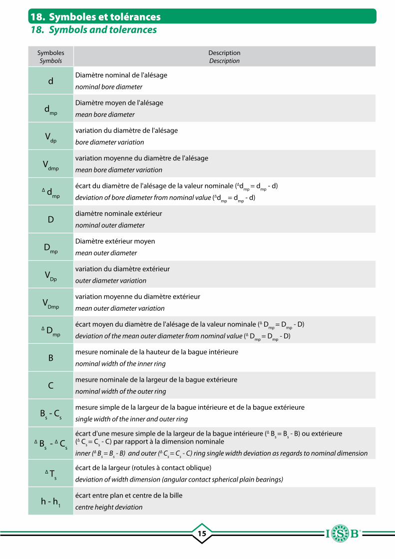
18. Symboles et tolérances18. Symbols and tolerances
SymbolesSymbols
DescriptionDescription
dDiamètre nominal de l'alésage
nominal bore diameter
dmp
Diamètre moyen de l'alésage
mean bore diameter
Vdp
variation du diamètre de l'alésage
bore diameter variation
Vdmp
variation moyenne du diamètre de l'alésage
mean bore diameter variation
∆ dmp
écart du diamètre de l'alésage de la valeur nominale (∆dmp
= dmp
- d)
deviation of bore diameter from nominal value (∆dmp
= dmp
- d)
Ddiamètre nominale extérieur
nominal outer diameter
Dmp
Diamètre extérieur moyen
mean outer diameter
VDp
variation du diamètre extérieur
outer diameter variation
VDmp
variation moyenne du diamètre extérieur
mean outer diameter variation
∆ Dmp
écart moyen du diamètre de l'alésage de la valeur nominale (∆ Dmp
= Dmp
- D)
deviation of the mean outer diameter from nominal value (∆ Dmp
= Dmp
- D)
Bmesure nominale de la hauteur de la bague intérieure
nominal width of the inner ring
Cmesure nominale de la largeur de la bague extérieure
nominal width of the outer ring
Bs - C
s
mesure simple de la largeur de la bague intérieure et de la bague extérieure
single width of the inner and outer ring
∆ Bs
- ∆ Cs
écart d'une mesure simple de la largeur de la bague intérieure (∆ Bs = B
s - B) ou extérieure
(∆ Cs = C
s - C) par rapport à la dimension nominale
inner (∆ Bs = B
s - B) and outer (∆ C
s = C
s - C) ring single width deviation as regards to nominal dimension
∆ Ts
écart de la largeur (rotules à contact oblique)
deviation of width dimension (angular contact spherical plain bearings)
h - h1
écart entre plan et centre de la bille
centre height deviation
16
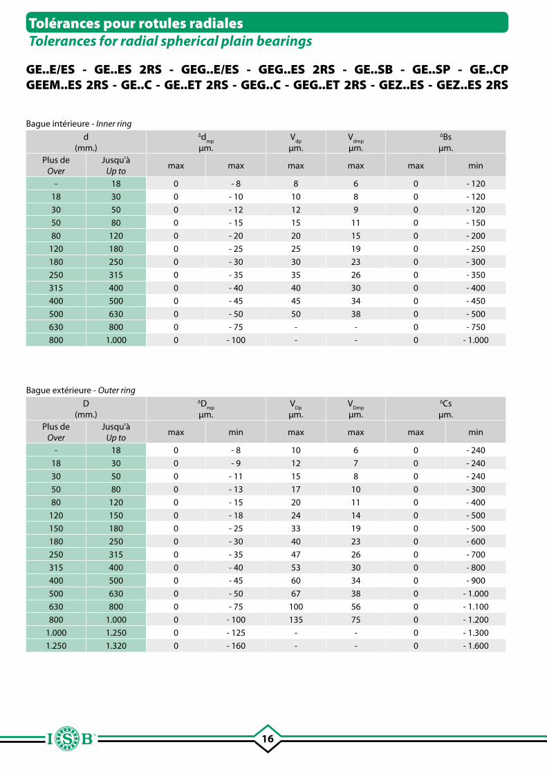
GE..E/ES - GE..ES 2RS - GEG..E/ES - GEG..ES 2RS - GE..SB - GE..SP - GE..CPGEEM..ES 2RS - GE..C - GE..ET 2RS - GEG..C - GEG..ET 2RS - GEZ..ES - GEZ..ES 2RS
Bague intérieure - Inner ring
d(mm.)
∆dmp
µm.
Vdp
µm.
Vdmp
µm.
∆Bs µm.
Plus deOver
Jusqu'àUp to
max max max max max min
- 18 0 - 8 8 6 0 - 120
18 30 0 - 10 10 8 0 - 120
30 50 0 - 12 12 9 0 - 120
50 80 0 - 15 15 11 0 - 150
80 120 0 - 20 20 15 0 - 200
120 180 0 - 25 25 19 0 - 250
180 250 0 - 30 30 23 0 - 300
250 315 0 - 35 35 26 0 - 350
315 400 0 - 40 40 30 0 - 400
400 500 0 - 45 45 34 0 - 450
500 630 0 - 50 50 38 0 - 500
630 800 0 - 75 - - 0 - 750
800 1.000 0 - 100 - - 0 - 1.000
Bague extérieure - Outer ring
D(mm.)
∆Dmp
µm.
VDp
µm.
VDmp
µm.
∆Cs µm.
Plus de Over
Jusqu'à Up to
max min max max max min
- 18 0 - 8 10 6 0 - 240
18 30 0 - 9 12 7 0 - 240
30 50 0 - 11 15 8 0 - 240
50 80 0 - 13 17 10 0 - 300
80 120 0 - 15 20 11 0 - 400
120 150 0 - 18 24 14 0 - 500
150 180 0 - 25 33 19 0 - 500
180 250 0 - 30 40 23 0 - 600
250 315 0 - 35 47 26 0 - 700
315 400 0 - 40 53 30 0 - 800
400 500 0 - 45 60 34 0 - 900
500 630 0 - 50 67 38 0 - 1.000
630 800 0 - 75 100 56 0 - 1.100
800 1.000 0 - 100 135 75 0 - 1.200
1.000 1.250 0 - 125 - - 0 - 1.300
1.250 1.320 0 - 160 - - 0 - 1.600
Tolérances pour rotules radiales Tolerances for radial spherical plain bearings
17
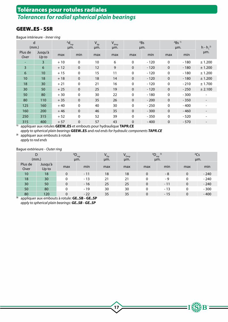
Tolérances pour rotules radiales Tolerances for radial spherical plain bearings
GEEW..ES - SSR
Bague intérieure - Inner ring
d (mm.)
∆dmp
µm.
Vdp
µm.
Vdmp
µm.
∆Bs µm.
∆Bs 1)
µm. h - h1
2) µm.
Plus de Over
Jusqu'àUp to
max min max max max min max min
- 3 + 10 0 10 6 0 - 120 0 - 180 ± 1.200
3 6 + 12 0 12 9 0 - 120 0 - 180 ± 1.200
6 10 + 15 0 15 11 0 - 120 0 - 180 ± 1.200
10 18 + 18 0 18 14 0 - 120 0 - 180 ± 1.200
18 30 + 21 0 21 16 0 - 120 0 - 210 ± 1.700
30 50 + 25 0 25 19 0 - 120 0 - 250 ± 2.100
50 80 + 30 0 30 22 0 - 180 0 - 300 -
80 110 + 35 0 35 26 0 - 200 0 - 350 -
125 160 + 40 0 40 30 0 - 250 0 - 400 -
160 200 + 46 0 46 35 0 - 300 0 - 460 -
250 315 + 52 0 52 39 0 - 350 0 - 520 -
315 400 + 57 0 57 43 0 - 400 0 - 570 -1) appliquer aux rotules GEEW..ES et embouts pour hydraulique TAPR.CE apply to spherical plain bearings GEEW..ES and rod ends for hydraulic components TAPR.CE2) appliquer aux embouts à rotule apply to rod ends
Bague extérieure - Outer ring
D (mm.)
∆Dmp
µm.
VDp
µm.
VDmp
µm.
∆Dmp
3)
µm.
∆Cs µm.
Plus deOver
Jusqu'àUp to
max min max max max min max min
10 18 0 - 11 18 18 0 - 8 0 - 24018 30 0 - 13 21 21 0 - 9 0 - 24030 50 0 - 16 25 25 0 - 11 0 - 24050 80 0 - 19 30 30 0 - 13 0 - 30080 120 0 - 22 35 35 0 - 15 0 - 400
3) appliquer aux embouts à rotule: GE..SB - GE..SP apply to spherical plain bearings: GE..SB - GE..SP
18
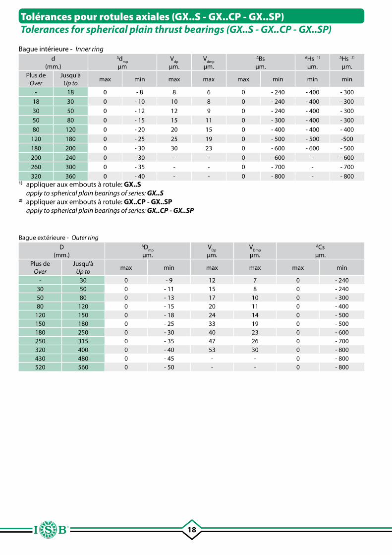
Bague intérieure - Inner ring d
(mm.)
∆dmp
µm
Vdp
µm.
Vdmp
µm.
∆Bs µm.
∆Hs 1)
µm.
∆Hs 2)
µm.Plus de
OverJusqu'à
Up tomax min max max max min min min
- 18 0 - 8 8 6 0 - 240 - 400 - 300
18 30 0 - 10 10 8 0 - 240 - 400 - 300
30 50 0 - 12 12 9 0 - 240 - 400 - 300
50 80 0 - 15 15 11 0 - 300 - 400 - 300
80 120 0 - 20 20 15 0 - 400 - 400 - 400
120 180 0 - 25 25 19 0 - 500 - 500 -500
180 200 0 - 30 30 23 0 - 600 - 600 - 500
200 240 0 - 30 - - 0 - 600 - - 600
260 300 0 - 35 - - 0 - 700 - - 700
320 360 0 - 40 - - 0 - 800 - - 8001) appliquer aux embouts à rotule: GX..S apply to spherical plain bearings of series: GX..S2) appliquer aux embouts à rotule: GX..CP - GX..SP apply to spherical plain bearings of series: GX..CP - GX..SP
Bague extérieure - Outer ring
D (mm.)
∆Dmp
µm.
VDp
µm.
VDmp
µm.
∆Cs µm.
Plus deOver
Jusqu'à Up to
max min max max max min
- 30 0 - 9 12 7 0 - 24030 50 0 - 11 15 8 0 - 24050 80 0 - 13 17 10 0 - 30080 120 0 - 15 20 11 0 - 400
120 150 0 - 18 24 14 0 - 500150 180 0 - 25 33 19 0 - 500180 250 0 - 30 40 23 0 - 600250 315 0 - 35 47 26 0 - 700320 400 0 - 40 53 30 0 - 800430 480 0 - 45 - - 0 - 800520 560 0 - 50 - - 0 - 800
Tolérances pour rotules axiales (GX..S - GX..CP - GX..SP)Tolerances for spherical plain thrust bearings (GX..S - GX..CP - GX..SP)
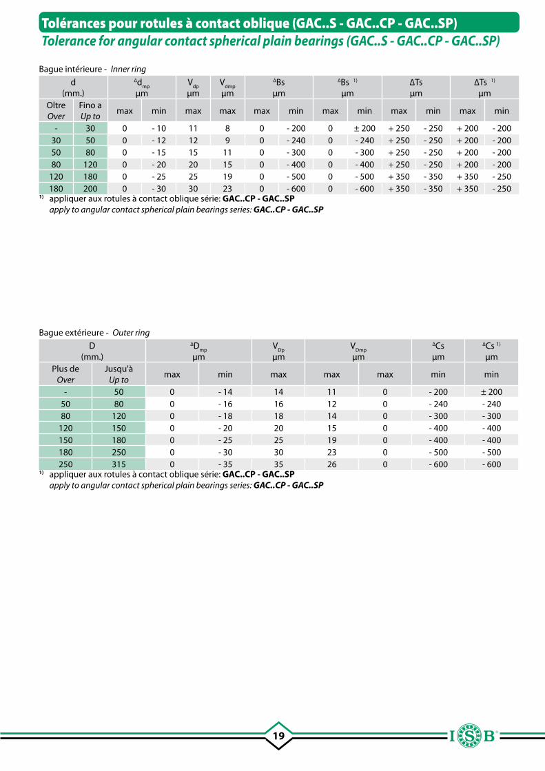
19
Tolérances pour rotules à contact oblique (GAC..S - GAC..CP - GAC..SP)Tolerance for angular contact spherical plain bearings (GAC..S - GAC..CP - GAC..SP)
Bague intérieure - Inner ring
d (mm.)
∆dmp
µm
Vdp
µm
Vdmp
µm
∆Bs µm
∆Bs 1)
µm∆Tsµm
∆Ts 1)
µmOltre Over
Fino aUp to
max min max max max min max min max min max min
- 30 0 - 10 11 8 0 - 200 0 ± 200 + 250 - 250 + 200 - 20030 50 0 - 12 12 9 0 - 240 0 - 240 + 250 - 250 + 200 - 20050 80 0 - 15 15 11 0 - 300 0 - 300 + 250 - 250 + 200 - 20080 120 0 - 20 20 15 0 - 400 0 - 400 + 250 - 250 + 200 - 200
120 180 0 - 25 25 19 0 - 500 0 - 500 + 350 - 350 + 350 - 250180 200 0 - 30 30 23 0 - 600 0 - 600 + 350 - 350 + 350 - 250
1) appliquer aux rotules à contact oblique série: GAC..CP - GAC..SP apply to angular contact spherical plain bearings series: GAC..CP - GAC..SP
Bague extérieure - Outer ring
D (mm.)
∆Dmp
µm
VDp
µm
VDmp
µm
∆Cs µm
∆Cs 1) µm
Plus de Over
Jusqu'àUp to
max min max max max min min
- 50 0 - 14 14 11 0 - 200 ± 20050 80 0 - 16 16 12 0 - 240 - 24080 120 0 - 18 18 14 0 - 300 - 300
120 150 0 - 20 20 15 0 - 400 - 400150 180 0 - 25 25 19 0 - 400 - 400180 250 0 - 30 30 23 0 - 500 - 500250 315 0 - 35 35 26 0 - 600 - 600
1) appliquer aux rotules à contact oblique série: GAC..CP - GAC..SP apply to angular contact spherical plain bearings series: GAC..CP - GAC..SP
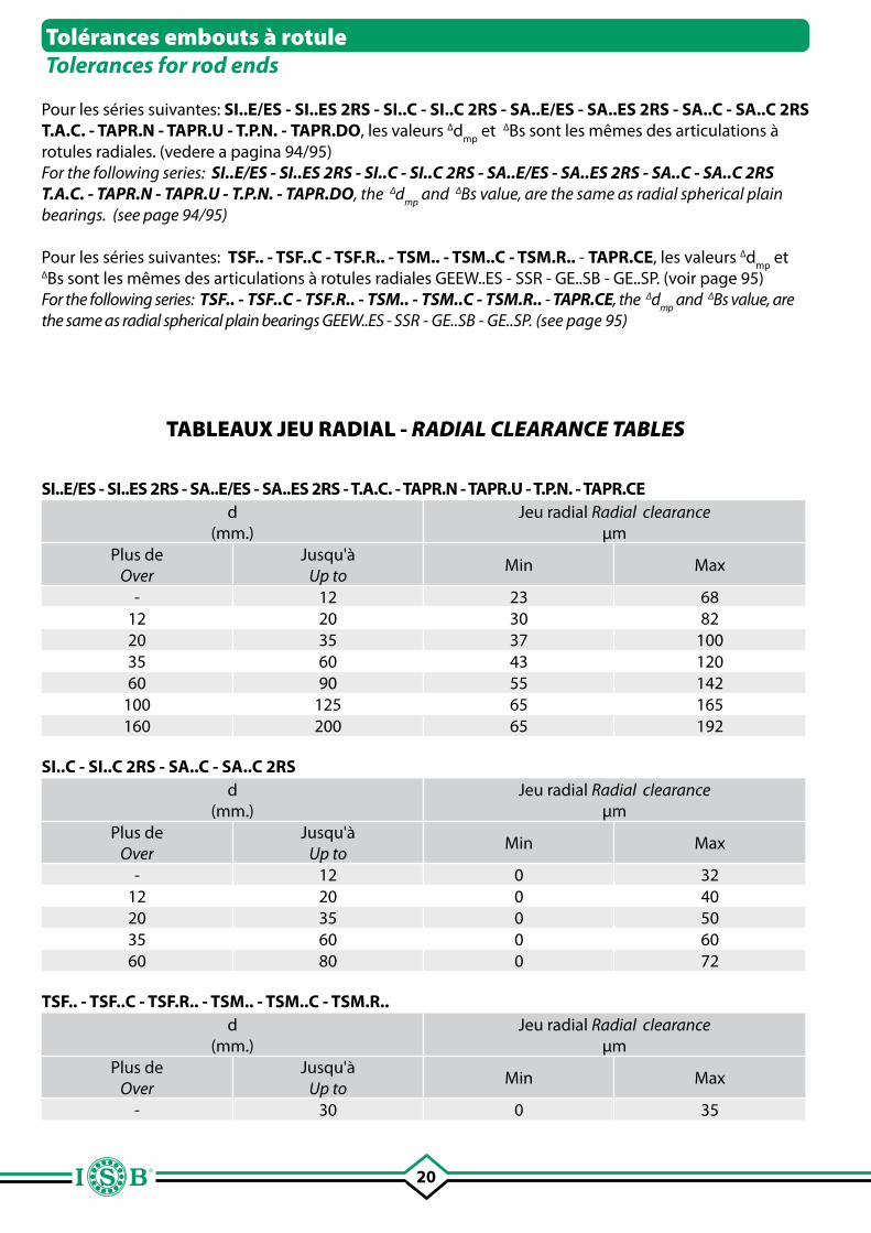
20
Pour les séries suivantes: SI..E/ES - SI..ES 2RS - SI..C - SI..C 2RS - SA..E/ES - SA..ES 2RS - SA..C - SA..C 2RS T.A.C. - TAPR.N - TAPR.U - T.P.N. - TAPR.DO, les valeurs ∆d
mp et ∆Bs sont les mêmes des articulations à
rotules radiales. (vedere a pagina 94/95)For the following series: SI..E/ES - SI..ES 2RS - SI..C - SI..C 2RS - SA..E/ES - SA..ES 2RS - SA..C - SA..C 2RS T.A.C. - TAPR.N - TAPR.U - T.P.N. - TAPR.DO, the ∆d
mp and ∆Bs value, are the same as radial spherical plain
bearings. (see page 94/95)
Pour les séries suivantes: TSF.. - TSF..C - TSF.R.. - TSM.. - TSM..C - TSM.R.. - TAPR.CE, les valeurs ∆dmp
et ∆Bs sont les mêmes des articulations à rotules radiales GEEW..ES - SSR - GE..SB - GE..SP. (voir page 95)For the following series: TSF.. - TSF..C - TSF.R.. - TSM.. - TSM..C - TSM.R.. - TAPR.CE, the ∆d
mp and ∆Bs value, are
the same as radial spherical plain bearings GEEW..ES - SSR - GE..SB - GE..SP. (see page 95)
Tolérances embouts à rotuleTolerances for rod ends
SI..E/ES - SI..ES 2RS - SA..E/ES - SA..ES 2RS - T.A.C. - TAPR.N - TAPR.U - T.P.N. - TAPR.CEd
(mm.)Jeu radial Radial clearance
µmPlus de
Over Jusqu'à
Up toMin Max
- 12 23 6812 20 30 8220 35 37 10035 60 43 12060 90 55 142
100 125 65 165160 200 65 192
SI..C - SI..C 2RS - SA..C - SA..C 2RS d
(mm.)Jeu radial Radial clearance
µmPlus de
Over Jusqu'à
Up toMin Max
- 12 0 3212 20 0 4020 35 0 5035 60 0 6060 80 0 72
TSF.. - TSF..C - TSF.R.. - TSM.. - TSM..C - TSM.R..d
(mm.)Jeu radial Radial clearance
µmPlus de
Over Jusqu'à
Up toMin Max
- 30 0 35
TABLEAUX JEU RADIAL - RADIAL CLEARANCE TABLES
21
19. Rotules exigeant l'entretien19. Maintenance spherical plain bearings
L'introduction des rotules, il y a plus d'un demi siècle, aussi bien exigeant l'entretien que sans entretien (autolubrifiante), a permis d'obtenir un avantage considérable, à savoir: la transmission du mouvement et la charge en absence de couples et donc en l'absence de charges radiales et de tension de flexion dans les éléments structuraux. L'utilisation des articulations à rotule est extrêmement variée justement parce qu'elle concerne tous les secteurs de construction de machines, équipements et véhicules automobiles. Normalement quand on parle de rotules, on entend avec combinaison acier/acier, des produits tout particulièrement utilisés en présence de charges alternées, contraintes de type dynamique et de choc. Le rotules à combinaison acier/acier, sont produites en utilisant l'acier haute qualité des roulements radiaux; les deux bagues sont usinées au tour, trempées et rectifiées sur tous les côtés, dont les surfaces de glissement sont ensuite traitées à travers un procédé (phosphatation au manganèse) désormais adoptée depuis un certain temps, puis protégées avec une couche de bisulfure de molybdène. Ce procédé garanti une excellente résistance à l'usure, à condition que les rotules soient lubrifiées aux intervalles prévus. Les rotules et embouts acier/acier peuvent être classés en trois catégories suivant la direction de la charge: radiales, axiales et à contact oblique.
20. Rotules radiales (exigeant l'entretien)20. Radial spherical plain bearings (requiring maintenance)
Les rotules radiales (exigeant l'entretien) sont formées par une bague intér ieure à alésage cylindrique et surface de glissement extérieure sphérique, et d'une bague extérieure à surface extérieure cylindrique et une surface de glissement interne sphérique creuse. Pour les dimensions jusqu'à 300 mm les bagues sont fendues dans le sens axial dans la phase de trempe; c'est justement cette dilatation de la bague extérieure fendue qui permet le montage de la bague intérieure. Les rotules radiales sont particulièrement adaptées à supporter des forces radiales élevées, comme par exemple celles des vérins hydrauliques.
With the introduction of spherical plain bearings, both those that require maintenance as well as those that do not require maintenance, since more than a half a century ago, it has been possible, thanks to their application, to obtain notable advantages, such as: the transmission of movement and load in the absence of cups and therefore in the absence of radial loads and flexion tension in the structural elements. The use of spherical plain bearings is extremely varied because it covers every sector of the construction of a machine, plants and vehicles.Normally when one speaks about spherical plain bearings, one intends coupled steel/steel, products particularly used in the presence of alternating loads, dynamic and crash t ype s o l i c i t a t i o n . T h e s p h e r i ca l p l a i n b e a r i n g s with steel/steel coupling are products which u s e p r e c i o u s s t e e l o f r e v o l v i n g b e a r i n g s ; together the rings are polished, tempered and rectified on all sides, the successively treated on the sliding sur face using (phosphate to manganese) procedure, adopted long ago, then successively protec ted with l a ye r s o f bisulphide of molybdenum This procedure insures excellent resistance to wear, given the bearings are lubricated at the foreseen intervals. The steel/steel spherical plain bearings can be divided into 3 categories based on the direction of the load: radial, axial and angular contact.
The radial spherical plain bearings (requiring maintenance) are formed with an internal ring with a cylindrical bore and sliding external spherical surface and with an external ring with a cylindrical external surface and a groove internal sliding spherical surface.For dimensions up to 300 mm. the external rings are spaced axially during the tempering phase; it is precisely this dilation of the external split ring that permits the mounting of the internal ring.The radial bearings are particularly adapt to support elevated radial force, like for example, those present in hydraulic cylinders.
22
21. Rotules axiales (exigeant l'entretien)21. Axial spherical plain bearings (requiring maintenance)
Les rotules axiales (exigeant l'entretien), quand l'application le prévoit, sont très appropriées en présence de charges axiales, elles peuvent toutefois aussi soutenir les efforts combinés des charges.Les rotules axiales ont des surfaces de contact à glissement dans l'arbre avec des roulements d'orientation pour le logement, disposés à angle par rapport à l'axe de la rotule. En présence de charges, la rondelle subit une expansion qui provoque l'élargissement de son diamètre. Pour éviter cette situation, en diminuant la part portante de la rotule, il convient d'utiliser un logement fermé aux dimensions appropriées, faisant opposition et permettant d'exploiter toutes les potentialités de la rotule de type axial.
Les rotules à contact oblique (exigeant l'entretien) sont formées par une rondelle-arbre à surface de glissement extérieure sphérique placée en oblique, et d'une rondelle de logement à surface de glissement interne sphérique creuse. Les rotules à contact oblique ont la caractéristique d'absorber les charges combinées (dans la direction axiale et radiale), elles peuvent donc être montées accouplées. Ils ont les mêmes dimensions d'encombrement que les roulements à rouleaux conique de la série 320..; elles peuvent par conséquent être un complément comme roulements de glissement, au cas où l'application des roulements radiaux devraient créer des complications de fonctionnement. En ce qui concerne leur entretien, les modèles standard exigent une lubrification à la graisse; d'autres types exigent une lubrification à bain d'huile à travers les gorges de lubrification.
22. Rotules à contact oblique (exigeant l'entretien)22. Angular contact spherical plain bearings (requiring maintenance)
Axial spherical plain bearings (requiring maintenance), as long as the applications p r o v i d e s , t h e s e b e a r i n g s a r e p a r t i c u l a r l y indicated in the presence of axial loads; never the less, they can even sustain, up to a certain force, combined loads.Axial spherical plain bearings, present running sur faces in the sha f t with washers for the housing placed at angles with respect to the axial of the bearing itself. When loads are present, the washer is subjected to an expansion which provokes it to enlarge in diameter. To obviate this situation, diminishing the size of the bearing it is opportune to use a closed housing which is the right size to take advantage of all of the potentiality of the axial type spherical plain bearing.
A n g u l a r c o n t a c t s p h e r i c a l p l a i n b e a r i n g s ( r e q u i r i n g m a i n t e n a n c e ) a r e c o n s t r u c t e d w i t h a wa s h e r f o r t h e s h a f t w i t h a s l i d i n g e x t e r n a l s p h e r i ca l s u r fa ce positioned obliquely and with a washer for housing with a s l iding concave spherical sur face. The spherical plain bearings with oblique contact have the characteristic of a b s o r b i n g c o m b i n e d l o a d s ( i n a x i a l a n d r a d i a l d i r e c t i o n ) , t h e y c a n t h e r e f o r e b e mounted in pairs (coupled) . They present t h e s a m e e n c u m b r a n c e a s s e r i e s 3 2 0 . . ; tapered roller bearings; they can therefore be supplementary as sliding bearings, where the application of revolving bearings would create functional complications. A for their maintenance, the standard models require a lubrication with grease; other types require a oil bath lubrication means a grooves.
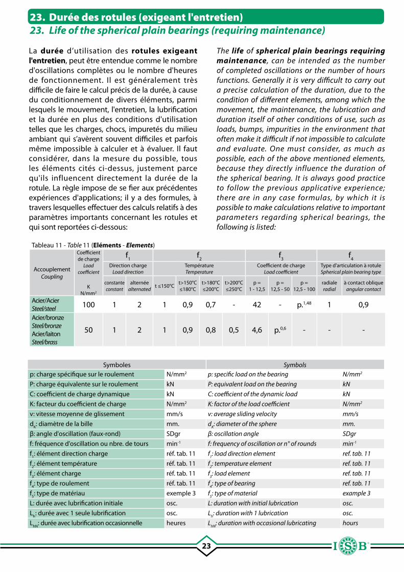
23
23. Durée des rotules (exigeant l'entretien)23. Life of the spherical plain bearings (requiring maintenance)
La durée d’utilisation des rotules exigeant l'entretien, peut être entendue comme le nombre d'oscillations complètes ou le nombre d'heures de fonctionnement. Il est généralement très difficile de faire le calcul précis de la durée, à cause du conditionnement de divers éléments, parmi lesquels le mouvement, l'entretien, la lubrification et la durée en plus des conditions d'utilisation telles que les charges, chocs, impuretés du milieu ambiant qui s’avèrent souvent difficiles et parfois même impossible à calculer et à évaluer. Il faut considérer, dans la mesure du possible, tous les éléments cités ci-dessus, justement parce qu'ils influencent directement la durée de la rotule. La règle impose de se fier aux précédentes expériences d'applications; il y a des formules, à travers lesquelles effectuer des calculs relatifs à des paramètres importants concernant les rotules et qui sont reportées ci-dessous:
Tableau 11 - Table 11 (Eléments - Elements)
AccouplementCoupling
Coefficient de charge
Load coefficient
KN/mm2
f1
f2
f3
f4
Direction charge Load direction
Température Temperature
Coefficient de chargeLoad coefficient
Type d'articulation à rotuleSpherical plain bearing type
constante constant
alternée alternated
t ≤150°Ct>150°C ≤180°C
t>180°C ≤200°C
t>200°C ≤250°C
p =1 - 12,5
p =12,5 - 50
p =12,5 - 100
radialeradial
à contact obliqueangular contact
Acier/AcierSteel/steel 100 1 2 1 0,9 0,7 - 42 - p.1,48 1 0,9
Acier/bronzeSteel/bronzeAcier/laitonSteel/brass
50 1 2 1 0,9 0,8 0,5 4,6 p.0,6 - - -
Symboles Symbolsp: charge spécifique sur le roulement N/mm2 p: specific load on the bearing N/mm2
P: charge équivalente sur le roulement kN P: equivalent load on the bearing kN
C: coefficient de charge dynamique kN C: coefficient of the dynamic load kN
K: facteur du coefficient de charge N/mm2 K: factor of the load coefficient N/mm2
v: vitesse moyenne de glissement mm/s v: average sliding velocity mm/s
dK: diamètre de la bille mm. d
K: diameter of the sphere mm.
β: angle d'oscillation (faux-rond) SDgr β: oscillation angle SDgr
f: fréquence d'oscillation ou nbre. de tours min-1 f: frequency of oscillation or n° of rounds min-1
f1: élément direction charge réf. tab. 11 f
1: load direction element ref. tab. 11
f2: élément température réf. tab. 11 f
2: temperature element ref. tab. 11
f3: élément charge réf. tab. 11 f
3: load element ref. tab. 11
f4: type de roulement réf. tab. 11 f
4: type of bearing ref. tab. 11
f5: type de matériau exemple 3 f
5: type of material example 3
L: durée avec lubrification initiale osc. L: duration with initial lubrication osc.
Lh: durée avec 1 seule lubrification osc. L
h: duration with 1 lubrication osc.
LhN
: durée avec lubrification occasionnelle heures LhN
: duration with occasional lubricating hours
The life of spherical plain bearings requiring maintenance, can be intended as the number of completed oscillations or the number of hours functions. Generally it is very difficult to carry out a precise calculation of the duration, due to the condition of different elements, among which the movement, the maintenance, the lubrication and duration itself of other conditions of use, such as loads, bumps, impurities in the environment that often make it difficult if not impossible to calculate and evaluate. One must consider, as much as possible, each of the above mentioned elements, because they directly influence the duration of the spherical bearing. It is always good practice to follow the previous applicative experience; there are in any case formulas, by which it is possible to make calculations relative to important parameters regarding spherical bearings, the following is listed:
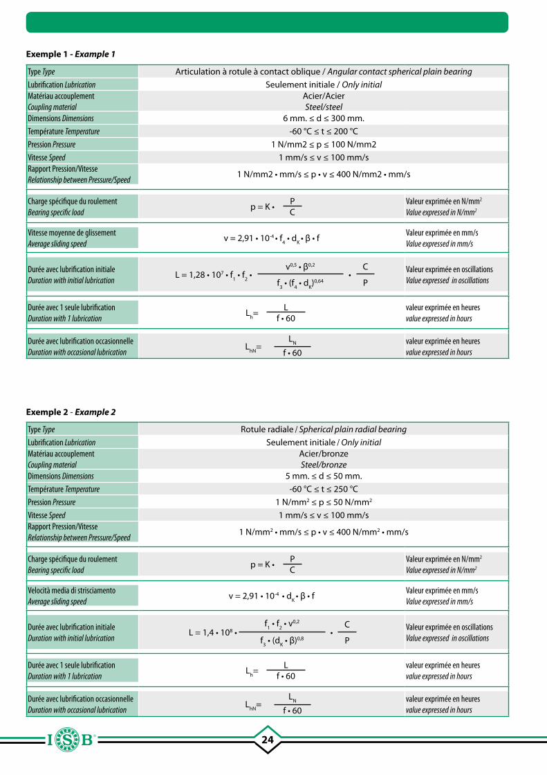
24
Exemple 1 - Example 1
Type Type Articulation à rotule à contact oblique / Angular contact spherical plain bearing
Lubrification Lubrication Seulement initiale / Only initialMatériau accouplement Coupling material
Acier/Acier Steel/steel
Dimensions Dimensions 6 mm. ≤ d ≤ 300 mm.
Température Temperature -60 °C ≤ t ≤ 200 °C
Pression Pressure 1 N/mm2 ≤ p ≤ 100 N/mm2
Vitesse Speed 1 mm/s ≤ v ≤ 100 mm/sRapport Pression/VitesseRelationship between Pressure/Speed
1 N/mm2 • mm/s ≤ p • v ≤ 400 N/mm2 • mm/s
Charge spécifique du roulement Bearing specific load
p = K •PC
Valeur exprimée en N/mm2
Value expressed in N/mm2
Vitesse moyenne de glissement Average sliding speed
v = 2,91 • 10-4 • f4 • d
K • β • f
Valeur exprimée en mm/s
Value expressed in mm/s
Durée avec lubrification initialeDuration with initial lubrication
L = 1,28 • 107 • f1 • f
2 •
v0,5 • β0,2
•C
f3 • (f
4 • d
K)0,64 P
Valeur exprimée en oscillations Value expressed in oscillations
Durée avec 1 seule lubrification Duration with 1 lubrication
Lh=
Lf • 60
valeur exprimée en heures value expressed in hours
Durée avec lubrification occasionnelleDuration with occasional lubrication
LhN
=L
N
f • 60valeur exprimée en heures value expressed in hours
Type Type Rotule radiale / Spherical plain radial bearing
Lubrification Lubrication Seulement initiale / Only initialMatériau accouplement Coupling material
Acier/bronze Steel/bronze
Dimensions Dimensions 5 mm. ≤ d ≤ 50 mm.
Température Temperature -60 °C ≤ t ≤ 250 °C
Pression Pressure 1 N/mm2 ≤ p ≤ 50 N/mm2
Vitesse Speed 1 mm/s ≤ v ≤ 100 mm/sRapport Pression/VitesseRelationship between Pressure/Speed
1 N/mm2 • mm/s ≤ p • v ≤ 400 N/mm2 • mm/s
Charge spécifique du roulement Bearing specific load
p = K •PC
Valeur exprimée en N/mm2
Value expressed in N/mm2
Velocità media di strisciamento Average sliding speed
v = 2,91 • 10-4 • dK
• β • fValeur exprimée en mm/s
Value expressed in mm/s
Durée avec lubrification initialeDuration with initial lubrication
L = 1,4 • 108 •f
1 • f
2 • v0,2
•C
f3 • (d
K • β)0,8 P
Valeur exprimée en oscillations Value expressed in oscillations
Durée avec 1 seule lubrification Duration with 1 lubrication
Lh=
Lf • 60
valeur exprimée en heures value expressed in hours
Durée avec lubrification occasionnelleDuration with occasional lubrication
LhN
=L
N
f • 60valeur exprimée en heures value expressed in hours
Exemple 2 - Example 2
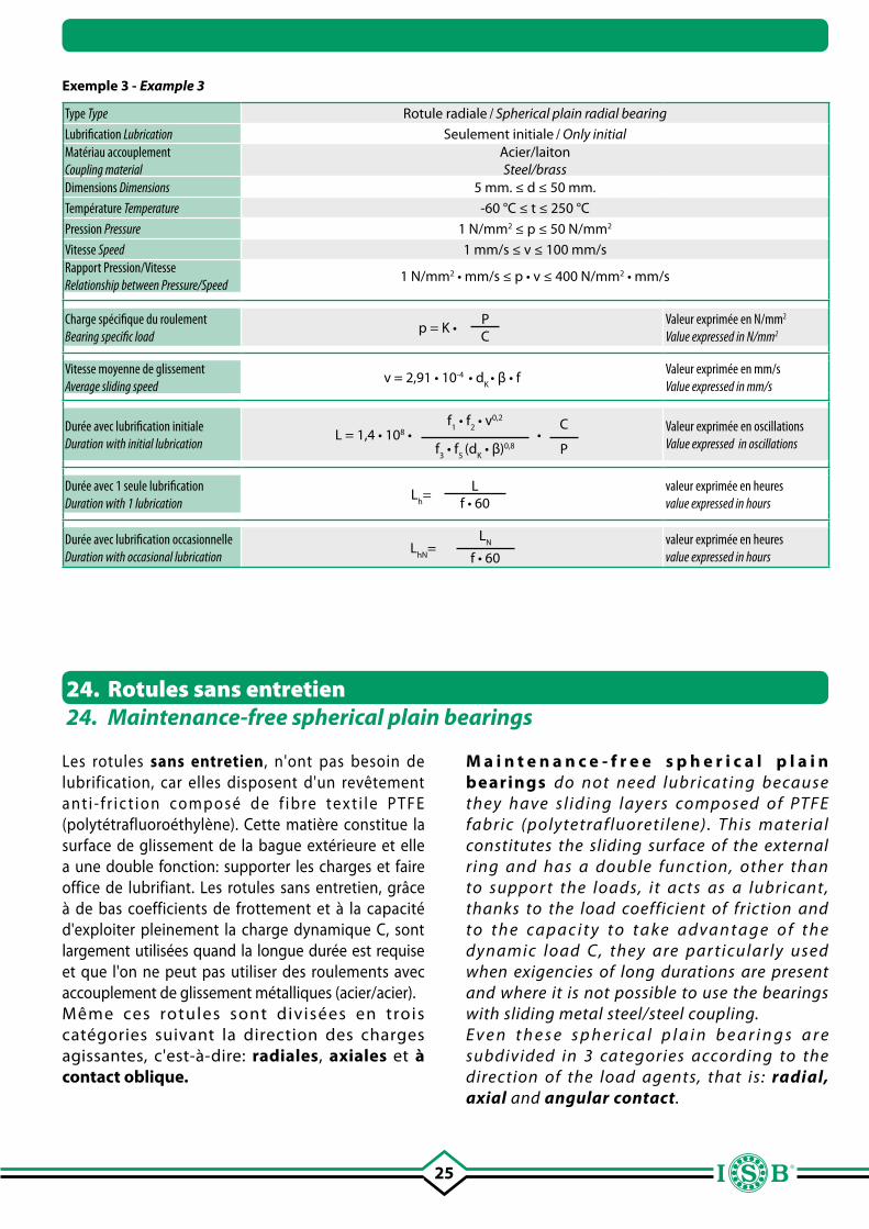
25
Exemple 3 - Example 3
Type Type Rotule radiale / Spherical plain radial bearing
Lubrification Lubrication Seulement initiale / Only initialMatériau accouplement Coupling material
Acier/laiton Steel/brass
Dimensions Dimensions 5 mm. ≤ d ≤ 50 mm.
Température Temperature -60 °C ≤ t ≤ 250 °C
Pression Pressure 1 N/mm2 ≤ p ≤ 50 N/mm2
Vitesse Speed 1 mm/s ≤ v ≤ 100 mm/sRapport Pression/VitesseRelationship between Pressure/Speed
1 N/mm2 • mm/s ≤ p • v ≤ 400 N/mm2 • mm/s
Charge spécifique du roulement Bearing specific load
p = K •PC
Valeur exprimée en N/mm2
Value expressed in N/mm2
Vitesse moyenne de glissement Average sliding speed
v = 2,91 • 10-4 • dK
• β • fValeur exprimée en mm/s
Value expressed in mm/s
Durée avec lubrification initialeDuration with initial lubrication
L = 1,4 • 108 •f
1 • f
2 • v0,2
•C
f3 • f
5 (d
K • β)0,8 P
Valeur exprimée en oscillations Value expressed in oscillations
Durée avec 1 seule lubrification Duration with 1 lubrication
Lh=
Lf • 60
valeur exprimée en heures value expressed in hours
Durée avec lubrification occasionnelleDuration with occasional lubrication
LhN
=L
N
f • 60valeur exprimée en heures value expressed in hours
Les rotules sans entretien, n'ont pas besoin de lubrification, car elles disposent d'un revêtement a nt i - f r i c t i o n co m p o s é d e f i b re te x t i l e P T F E (polytétrafluoroéthylène). Cette matière constitue la surface de glissement de la bague extérieure et elle a une double fonction: supporter les charges et faire office de lubrifiant. Les rotules sans entretien, grâce à de bas coefficients de frottement et à la capacité d'exploiter pleinement la charge dynamique C, sont largement utilisées quand la longue durée est requise et que l'on ne peut pas utiliser des roulements avec accouplement de glissement métalliques (acier/acier). Même ces rotules sont divisées en trois catégories suivant la direction des charges agissantes, c'est-à-dire: radiales, axiales et à contact oblique.
24. Rotules sans entretien24. Maintenance-free spherical plain bearings
M a i n t e n a n c e - f r e e s p h e r i c a l p l a i n bearings do not need lubricating because they have s l iding layers composed of PTFE fabric (polytetrafluoreti lene). This material constitutes the sliding surface of the external ring and has a double function, other than to suppor t the loads, it acts as a lubricant, thanks to the load coefficient of friction and t o t h e ca p a c i t y t o t a ke a d va n t a g e o f t h e dynamic load C, they are par ticularly used when exigencies of long durations are present and where it is not possible to use the bearings with sliding metal steel/steel coupling.E v e n t h e s e s p h e r i c a l p l a i n b e a r i n g s a r e subdivided in 3 categories according to the direction of the load agents, that is: radial, axial and angular contact.
26
26. Rotules axiales (sans entretien)26. Axial spherical plain bearings (maintenance-free)
Les rotules axiales (sans entretien), ont des surfaces de contact à glissement dans l'arbre avec rondelle pour le logement disposées à angle par rapport à l'axe de la rotule elle même; la surface chromée a la forme d’une calotte et se trouve dans la zone de frottement en forme de cavité sphérique revêtue de fibre PTFE. Pour les dimensions d'alésage max de 140 mm, elles sont produites avec de l'acier pour roulement, trempées avec finition par usinage d'ultra-précision. Les rotules axiales, vue la structure, sont indiquées pour absorber les charges unidirectionnelles, surtout dans la direction axiale. Sous effort, le diamètre de la rondelle de logement se dilate; pour éviter cette condition, on peut utiliser un siège fermé et dimensionné correctement, faisant contraste et permettant d'exploiter toute les potentialités de la rotule axiale. Tous les composants des rotules sont réalisés et adaptés aux contre-pièces respectives, par conséquent il ne sont pas interchangeables.
25. Rotules radiales (sans entretien)25. Radial spherical plain bearings (maintenance-free)
Les rotules radiales (sans entretien) sont formées d'une bague intérieure trempée en acier pour roulements radiaux avec surface chromée et d'une bague extérieure composée de deux douilles introduites l'une dans l'autre en utilisant la méthode du “rivetage”. Successivement le revêtement en acier de la bague extérieure est usiné avec précision et entre ce dernier et la bague intérieure est placé la fibre de PTFE.Pour certains types de rotules, version 2RS, les bagues extérieures ont une fente, tandis que pour les dimensions supérieure, les bagues extérieures sont divisées et soudées à l'aide de rondelles à forte résistance.La principale caractéristiques de ce type de rotules est d'absorber les charges radiales, provenant toujours de la même direction.
Axial spherical plain bearings (maintenance-free) present contact surfaces with running shafts with washers for housing provided with angles with respect to the axial of the bearing itself; the chromed surface is in the form of a cap and is positioned in the sliding zone in the form of a spherical cavity covered with PTFE fabric. For bore dimensions within 140 mm., they are produced with steel for revolving bearings, tempered and refined with extremely precise equipment. The axial spherical plain bearings, considering the structure, are indicated to absorb undirectional load, especially in axial directions. Under force, there is a diameter dilation of the washer for housing; to obviate this situation, it is possible to use a closed seat with the correct dimensions, that faces the contrast and consents taking advantage of the potential of the axial spherical plain bearing. All of the single components of the bearings are realized and adapted to correspective counterparts, and therefore it is not possible to interchange them.
R a d i a l s p h e r i c a l p l a i n b e a r i n g s (maintenance-free) are formed by an internal tempered steel r ing for revolving bearings with chromed surfaces and with external rings composed of 2 bushes inserted one inside the other using the “riveting” method.In a subsequent phase, the steel covering of the external ring is worked with precision, between the internal and the external r ing the PTFE material is collocated. For some type of 2RS spherical plain execution, the ex ternal r ings present a split while for superior dimensions, the external rings are divided and soldered by washers with massive strength.The principal charac terist ic of this t ype of bearing is the radial load absorption always deriving from the same direction.
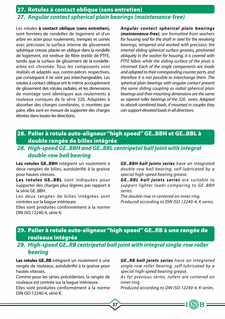
27
Les rotules à contact oblique (sans entretien), sont formées de rondelles de logement et d'un arbre en acier pour roulements, trempés et usinés avec précision; la surface interne de glissement sphérique creuse, placée en oblique dans la rondelle de logement, est revêtue de fibre textile de PTFE, tandis que la surface de glissement de la rondelle-arbre est chromée. Tous les composants sont réalisés et adaptés aux contre-pièces respectives, par conséquent il ne sont pas interchangeables. Les rotules à contact oblique ont le même accouplement de glissement des rotules radiales, et les dimensions de montage sont identiques aux roulements à rouleaux coniques de la série 320. Adaptées à absorber des charges combinées, si montées par paire, elles sont en mesure de supporter des charges élevées dans toutes les directions.
Les rotules GE..BBH intègrent un roulement à deux rangées de billes, autolubrifié à la graisse pour hautes vitesses.Les rotules GE..BBL sont indiquées pour supporter des charges plus légères par rapport à la série GE..BBH.Les deux rangées de billes intégrées sont centrées sur la bague intérieure.Elles sont produites conformément à la norme DIN ISO 12240-4, série K.
Les rotules GE..RB intègrent un roulement à une rangée de rouleaux, autolubrifié à la graisse pour hautes vitesses.Comme pour les séries précédentes, la rangée de rouleaux est centrée sur la bague intérieure.Elles sont produites conformément à la norme DIN ISO 12240-4, série K.
27. Rotules à contact oblique (sans entretien)27. Angular contact spherical plain bearings (maintenance-free)
28. Palier à rotule auto-aligneur “high speed” GE..BBH et GE..BBL à double rangée de billes intégrée
28. High-speed GE..BBH and GE..BBL centripetal ball joint with integral double-row ball bearing
29. Palier à rotule auto-aligneur “high speed” GE..RB à une rangée de rouleaux intégrée
29. High-speed GE..RB centripetal ball joint with integral single-row roller bearing
Angular contact spherical plain bearings (maintenance-free), are formatted from washers for housing and for the shaft in steel for the revolving bearings, tempered and worked with precision; the internal sliding spherical surface grooves, positioned obliquely in the washer for housing, it is covered with PTFE fabric while the sliding surface of the pivot is chromed. Each of the single components are made and adapted to their corresponding counter parts, and therefore it is not possible to interchange them. The spherical plain bearings with angular contact present the same sliding coupling as radial spherical plain bearings and their mounting dimensions are the same as tapered roller bearings of the 320.. series. Adapted to absorb combined loads, if mounted in couples they can support elevated loads in all directions.
GE..BBH ball joints series have an integrated double-row ball bearing, self-lubricated by a special high-speed bearing grease.GE..BBL ball joints series are suitable to suppor t l ighter loads comparing to GE..BBH series.The double-row in centered on inner ring.Produced according to DIN ISO 12240-4, K series.
GE..RB ball joints series have an integrated single-row roller bearing, self-lubricated by a special high-speed bearing grease.As for previous series, rollers are centered on inner ring.Produced according to DIN ISO 12240-4, K series.
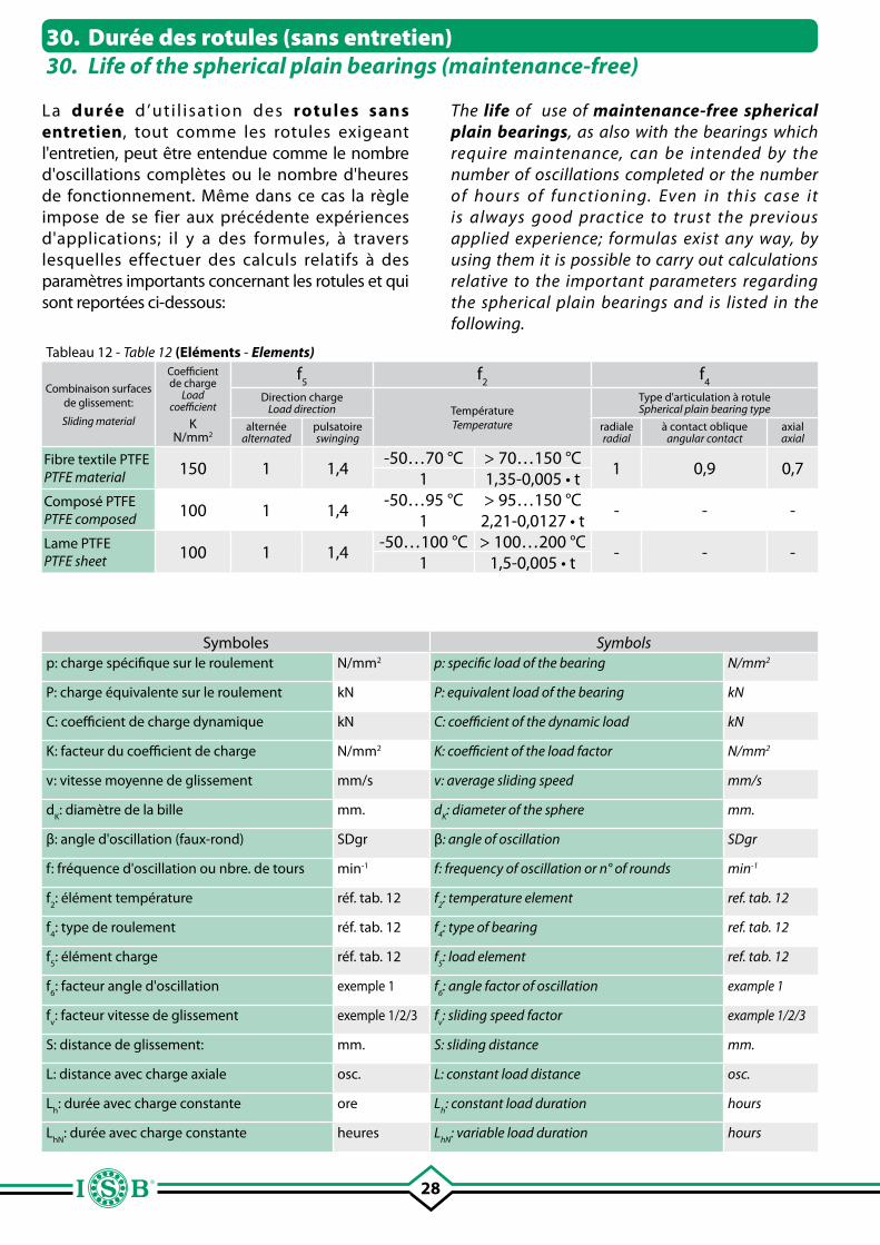
28
La durée d ’ut i l isat ion des rotules sans entretien, tout comme les rotules exigeant l'entretien, peut être entendue comme le nombre d'oscillations complètes ou le nombre d'heures de fonctionnement. Même dans ce cas la règle impose de se fier aux précédente expériences d'applications; il y a des formules, à travers lesquelles effectuer des calculs relatifs à des paramètres importants concernant les rotules et qui sont reportées ci-dessous:
Tableau 12 - Table 12 (Eléments - Elements)
Combinaison surfaces de glissement:
Sliding material
Coefficient de charge
Load coefficient
KN/mm2
f5
f2
f4
Direction charge Load direction Température
Temperature
Type d'articulation à rotuleSpherical plain bearing type
alternée alternated
pulsatoire swinging
radialeradial
à contact obliqueangular contact
axialaxial
Fibre textile PTFEPTFE material 150 1 1,4
-50…70 °C > 70…150 °C1 0,9 0,7
1 1,35-0,005 • tComposé PTFEPTFE composed 100 1 1,4
-50…95 °C > 95…150 °C- - -
1 2,21-0,0127 • tLame PTFEPTFE sheet 100 1 1,4
-50…100 °C > 100…200 °C- - -
1 1,5-0,005 • t
Symboles Symbolsp: charge spécifique sur le roulement N/mm2 p: specific load of the bearing N/mm2
P: charge équivalente sur le roulement kN P: equivalent load of the bearing kN
C: coefficient de charge dynamique kN C: coefficient of the dynamic load kN
K: facteur du coefficient de charge N/mm2 K: coefficient of the load factor N/mm2
v: vitesse moyenne de glissement mm/s v: average sliding speed mm/s
dK: diamètre de la bille mm. d
K: diameter of the sphere mm.
β: angle d'oscillation (faux-rond) SDgr β: angle of oscillation SDgr
f: fréquence d'oscillation ou nbre. de tours min-1 f: frequency of oscillation or n° of rounds min-1
f2: élément température réf. tab. 12 f
2: temperature element ref. tab. 12
f4: type de roulement réf. tab. 12 f
4: type of bearing ref. tab. 12
f5: élément charge réf. tab. 12 f
5: load element ref. tab. 12
f6: facteur angle d'oscillation exemple 1 f
6: angle factor of oscillation example 1
fv: facteur vitesse de glissement exemple 1/2/3 f
v: sliding speed factor example 1/2/3
S: distance de glissement: mm. S: sliding distance mm.
L: distance avec charge axiale osc. L: constant load distance osc.
Lh: durée avec charge constante ore L
h: constant load duration hours
LhN
: durée avec charge constante heures LhN
: variable load duration hours
30. Durée des rotules (sans entretien)30. Life of the spherical plain bearings (maintenance-free)
The life of use of maintenance-free spherical plain bearings, as also with the bearings which require maintenance, can be intended by the number of oscillations completed or the number of hours of functioning. Even in this case it is always good practice to trust the previous applied experience; formulas exist any way, by using them it is possible to carry out calculations relative to the important parameters regarding the spherical plain bearings and is listed in the following.
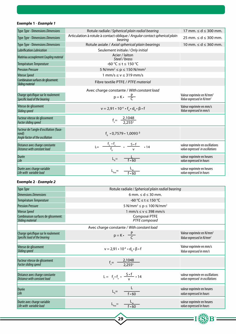
29
Exemple 1 - Example 1
Type Type - Dimensions Dimensions Rotule radiale / Spherical plain radial bearing 17 mm. ≤ d ≤ 300 mm.
Type Type - Dimensions Dimensions Articulation à rotule à contact oblique / Angular contact spherical plain bearing 25 mm. ≤ d ≤ 300 mm.
Type Type - Dimensions Dimensions Rotule axiale / Axial spherical plain bearings 10 mm. ≤ d ≤ 360 mm.
Lubrification Lubrication Seulement initiale / Only initial
Matériau accouplement Coupling material Acier / laiton Steel / brass
Température Temperature -60 °C ≤ t ≤ 150 °C
Pression Pressure 5 N/mm2 ≤ p ≤ 150 N/mm2
Vitesse Speed 1 mm/s ≤ v ≤ 319 mm/sCombinaison surfaces de glissement: Sliding material Fibre textile PTFE / PTFE material
Avec charge constante / With constant loadCharge spécifique sur le roulement Specific load of the bearing p = K • P
CValeur exprimée en N/mm2
Value expressed in N/mm2
Vitesse de glissement Sliding speed
v = 2,91 • 10-4 • f4 • d
K • β • f Valeur exprimée en mm/s
Value expressed in mm/s
Facteur vitesse de glissement Factor sliding speed f
v=
2,10482,255x
Facteur de l'angle d'oscillation (faux-rond) Angle factor of the oscillation
f6 • 0,7579 • 1,0093 β
Distance avec charge constanteDistance with constant load L=
f2 • f
v•
S • f• 14f
6 vvaleur exprimée en oscillations value expressed in oscillations
DuréeLife L
h= L
f • 60valeur exprimée en heures value expressed in hours
Durée avec charge variableLife with variable load L
hw=
Lw
f • 60valeur exprimée en heures value expressed in hours
Type Type Rotule radiale / Spherical plain radial bearing
Dimensions Dimensions 6 mm. ≤ d ≤ 30 mm.
Température Temperature -60 °C ≤ t ≤ 150 °C
Pression Pressure 5 N/mm2 ≤ p ≤ 100 N/mm2
Vitesse Speed 1 mm/s ≤ v ≤ 398 mm/sCombinaison surfaces de glissement:Sliding material
Composé PTFEPTFE composed
Avec charge constante / With constant load
Charge spécifique sur le roulement Specific load of the bearing p = K •
PC
Valeur exprimée en N/mm2
Value expressed in N/mm2
Vitesse de glissement Sliding speed v = 2,91 • 10-4 • d
K • β • f
Valeur exprimée en mm/s
Value expressed in mm/s
Facteur vitesse de glissementFactor sliding speed f
v=
2,10482,255x
Distance avec charge constante Distance with constant load L = f
2 • f
v •
S • f• 14
vvaleur exprimée en oscillations value expressed in oscillations
DuréeLife L
h=
L
f • 60valeur exprimée en heures value expressed in hours
Durée avec charge variableLife with variable load L
hw=
Lw
f • 60valeur exprimée en heures value expressed in hours
Exemple 2 - Example 2
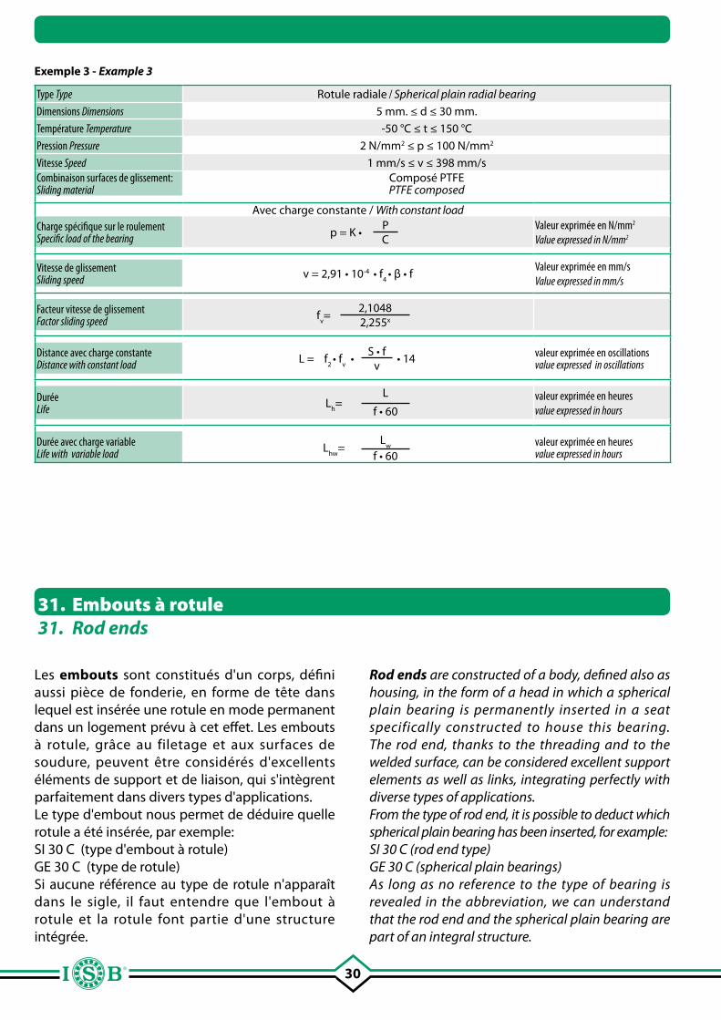
30
Exemple 3 - Example 3
Type Type Rotule radiale / Spherical plain radial bearing
Dimensions Dimensions 5 mm. ≤ d ≤ 30 mm.
Température Temperature -50 °C ≤ t ≤ 150 °C
Pression Pressure 2 N/mm2 ≤ p ≤ 100 N/mm2
Vitesse Speed 1 mm/s ≤ v ≤ 398 mm/sCombinaison surfaces de glissement:Sliding material
Composé PTFEPTFE composed
Avec charge constante / With constant loadCharge spécifique sur le roulement Specific load of the bearing p = K •
PC
Valeur exprimée en N/mm2
Value expressed in N/mm2
Vitesse de glissement Sliding speed v = 2,91 • 10-4 • f
4 • β • f
Valeur exprimée en mm/s
Value expressed in mm/s
Facteur vitesse de glissementFactor sliding speed f
v=
2,10482,255x
Distance avec charge constante Distance with constant load L = f
2 • f
v •
S • f• 14
vvaleur exprimée en oscillations value expressed in oscillations
DuréeLife L
h=
L
f • 60valeur exprimée en heures value expressed in hours
Durée avec charge variableLife with variable load L
hw=
Lw
f • 60valeur exprimée en heures value expressed in hours
31. Embouts à rotule31. Rod ends
Les embouts sont constitués d'un corps, défini aussi pièce de fonderie, en forme de tête dans lequel est insérée une rotule en mode permanent dans un logement prévu à cet effet. Les embouts à rotule, grâce au filetage et aux surfaces de soudure, peuvent être considérés d'excellents éléments de support et de liaison, qui s'intègrent parfaitement dans divers types d'applications.Le type d'embout nous permet de déduire quelle rotule a été insérée, par exemple:SI 30 C (type d'embout à rotule)GE 30 C (type de rotule)Si aucune référence au type de rotule n'apparaît dans le sigle, il faut entendre que l'embout à rotule et la rotule font partie d'une structure intégrée.
Rod ends are constructed of a body, defined also as housing, in the form of a head in which a spherical plain bearing is permanently inserted in a seat specifically constructed to house this bearing. The rod end, thanks to the threading and to the welded surface, can be considered excellent support elements as well as links, integrating perfectly with diverse types of applications.From the type of rod end, it is possible to deduct which spherical plain bearing has been inserted, for example:SI 30 C (rod end type)GE 30 C (spherical plain bearings)As long as no reference to the type of bearing is revealed in the abbreviation, we can understand that the rod end and the spherical plain bearing are part of an integral structure.
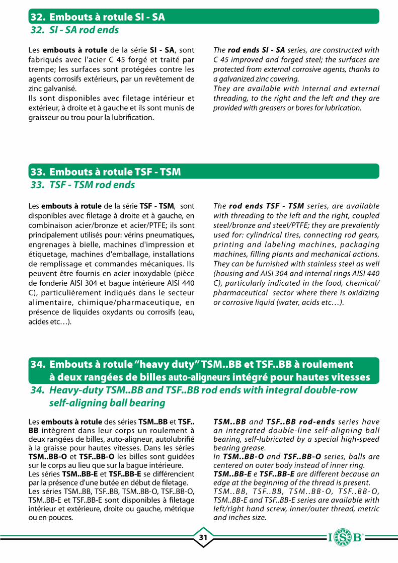
31
32. Embouts à rotule SI - SA32. SI - SA rod ends
Les embouts à rotule de la série SI - SA, sont fabriqués avec l'acier C 45 forgé et traité par trempe; les surfaces sont protégées contre les agents corrosifs extérieurs, par un revêtement de zinc galvanisé. Ils sont disponibles avec filetage intérieur et extérieur, à droite et à gauche et ils sont munis de graisseur ou trou pour la lubrification.
Les embouts à rotule de la série TSF - TSM, sont disponibles avec filetage à droite et à gauche, en combinaison acier/bronze et acier/PTFE; ils sont principalement utilisés pour: vérins pneumatiques, engrenages à bielle, machines d'impression et étiquetage, machines d'emballage, installations de remplissage et commandes mécaniques. Ils peuvent être fournis en acier inoxydable (pièce de fonderie AISI 304 et bague intérieure AISI 440 C), particulièrement indiqués dans le secteur alimentaire, chimique/pharmaceutique, en présence de liquides oxydants ou corrosifs (eau, acides etc…).
33. Embouts à rotule TSF - TSM 33. TSF - TSM rod ends
34. Embouts à rotule “heavy duty” TSM..BB et TSF..BB à roulement à deux rangées de billes auto-aligneurs intégré pour hautes vitesses
34. Heavy-duty TSM..BB and TSF..BB rod ends with integral double-row self-aligning ball bearing
Les embouts à rotule des séries TSM..BB et TSF.. BB intègrent dans leur corps un roulement à deux rangées de billes, auto-aligneur, autolubrifié à la graisse pour hautes vitesses. Dans les séries TSM..BB-O et TSF..BB-O les billes sont guidées sur le corps au lieu que sur la bague intérieure.Les séries TSM..BB-E et TSF..BB-E se différencient par la présence d'une butée en début de filetage.Les séries TSM..BB, TSF..BB, TSM..BB-O, TSF..BB-O, TSM..BB-E et TSF..BB-E sont disponibles à filetage intérieur et extérieure, droite ou gauche, métrique ou en pouces.
The rod ends SI - SA series, are constructed with C 45 improved and forged steel; the surfaces are protected from external corrosive agents, thanks to a galvanized zinc covering. They are available with internal and external threading, to the right and the left and they are provided with greasers or bores for lubrication.
The rod ends TSF - TSM series, are available with threading to the left and the right, coupled steel/bronze and steel/PTFE; they are prevalently used for: cylindrical tires, connecting rod gears, printing and labeling machines, packaging machines, filling plants and mechanical actions. They can be furnished with stainless steel as well (housing and AISI 304 and internal rings AISI 440 C), particularly indicated in the food, chemical/pharmaceutical sector where there is oxidizing or corrosive liquid (water, acids etc…).
TSM..BB and TSF..BB rod- ends series have an integrated double-line self- aligning ball bearing, self-lubricated by a special high-speed bearing grease.In TSM..BB-O and TSF..BB-O series, balls are centered on outer body instead of inner ring.TSM..BB-E e TSF..BB-E are different because an edge at the beginning of the thread is present.T S M . . B B , T S F. . B B , T S M . . B B - O , T S F. . B B - O , TSM..BB-E and TSF..BB-E series are available with left/right hand screw, inner/outer thread, metric and inches size.
32
37. Embouts à rotule pour hydraulique à corps forgé soudable T.A.C. - T.P.N.37. Rod ends for hydraulic with weld able housing T.A.C. - T.P.N.
Il existe deux types d'embouts à rotule pour l'hydraulique avec corps soudable, tous deux disponibles dans la combinaison acier/acier. Le premier (T.A.C.), fabriqué en acier forgé, prévoit aux extrémités circulaires, un chanfrein de soudure à 45° qui permet un soudage facile à la tige du piston; ils peuvent être centrés grâce à une broche de référence placée au centre de la surface d'appui. La rotule est fixée axialement dans le trou de montage grâce à un bord.Le deuxième type (T.P.N.), construit en acier forgé jusqu'à un diamètre de 50 mm, au-delà il est produit en acier laminé, avec les extrémités à souder de forme rectangulaire, ce qui facilite considérablement l'assemblage sur les fonds des vérins; les rotules sont fixées axialement dans le trou de montage au moyen de deux bagues de sûreté.
36. Embouts à rotule pour hydraulique TAPR.N - TAPR.U - TAPR.DO - TAPR.CE36. Rod ends for hydraulic TAPR.N - TAPR.U - TAPR.DO - TAPR.CE
35. Embouts “heavy duty” TSM..RB et TSF..RB à roulement à une rangée de rouleaux auto-aligneurs intégré
35. Heavy-duty TSM..RB and TSF..RB rod ends with integral single-row self-aligning roller bearing
Ils sont produits conformément à la norme DIN ISO 12240-4, série K.Les embouts à rotule pour l'hydraulique , sont formés d'un corps taraudé avec une coupe longitudinale et deux vis six pans creux permettant le blocage sur la tige filetée. Au moyen de deux bagues de sûreté, les rotules, dans la combinaison acier/acier, sont fixées axialement dans le trou de montage. Les embouts à rotule pour l'hydraulique sont fabriqués en acier forgé C45, jusqu'à un diamètre nominal de 50 mm, au-delà on utilise la fonte à graphite sphéroïdal; les surfaces sont traitées pour résister à la corrosion.
Les embouts à rotule des séries TSM..RB et TSF.. RB intègrent dans leur corps un roulement à une rangée de rouleaux, autolubrifié à la graisse pour hautes vitesses.Les séries TSM..RB et TSF..RB sont disponibles avec filetage intérieur et extérieur, droite ou gauche, métriques ou en pouces.Elles sont produites conformément à la norme DIN ISO 12240-4, série K.
There are two types of rod ends for hydraulics with weld able housing ; both are available in steel/steel coupling. The first type ( T.A.C.), constructed in forged steel, provides for circular extremes, a blunted welding at 45° that permits easy welding to the stem of the piston; they are can be centered using a reference pin situated at the center of the support surface. The spherical plain bearing is fixed axially in the mounting bore thanks to a border.The second type ( T.P.N.), constructed in forged s t e e l u p t o a 5 0 m m . b o r e d i a m e t e r a n d produced in laminated steel, presents extremes of welding in rectangular form, this particular facilitates notably the assembly on the bottoms of cylinders; using two rings for security the bearings are fixed axially in the mounting bore.
Produced according to DIN ISO 12240-4, K series.Ro d e n d s f o r hyd ra u l i c , a re f o r m e d by a threaded stem with a lengthwise cut and two incased hexagon screws which permit blockage on the threads of the pole. Using two security rings, the bearings, in steel/steel coupling, are fixed axially in the mounting bore.The rod ends for hydraulics are constructed in forged C45 steel, until a nominal diameter of 50 mm., in addition, spheroid cast iron is used and the surfaces are treated to resist corrosion.
TSM..RB and TSF..RB rod- ends series have an integrated single line roller bearing, self-lubricated by a special high-speed bearing grease.TSM..RB and TSF..RB series are available with left/right hand screw, inner/ outer thread, metric and inches.Produced according to DIN ISO 12240-4, K series.
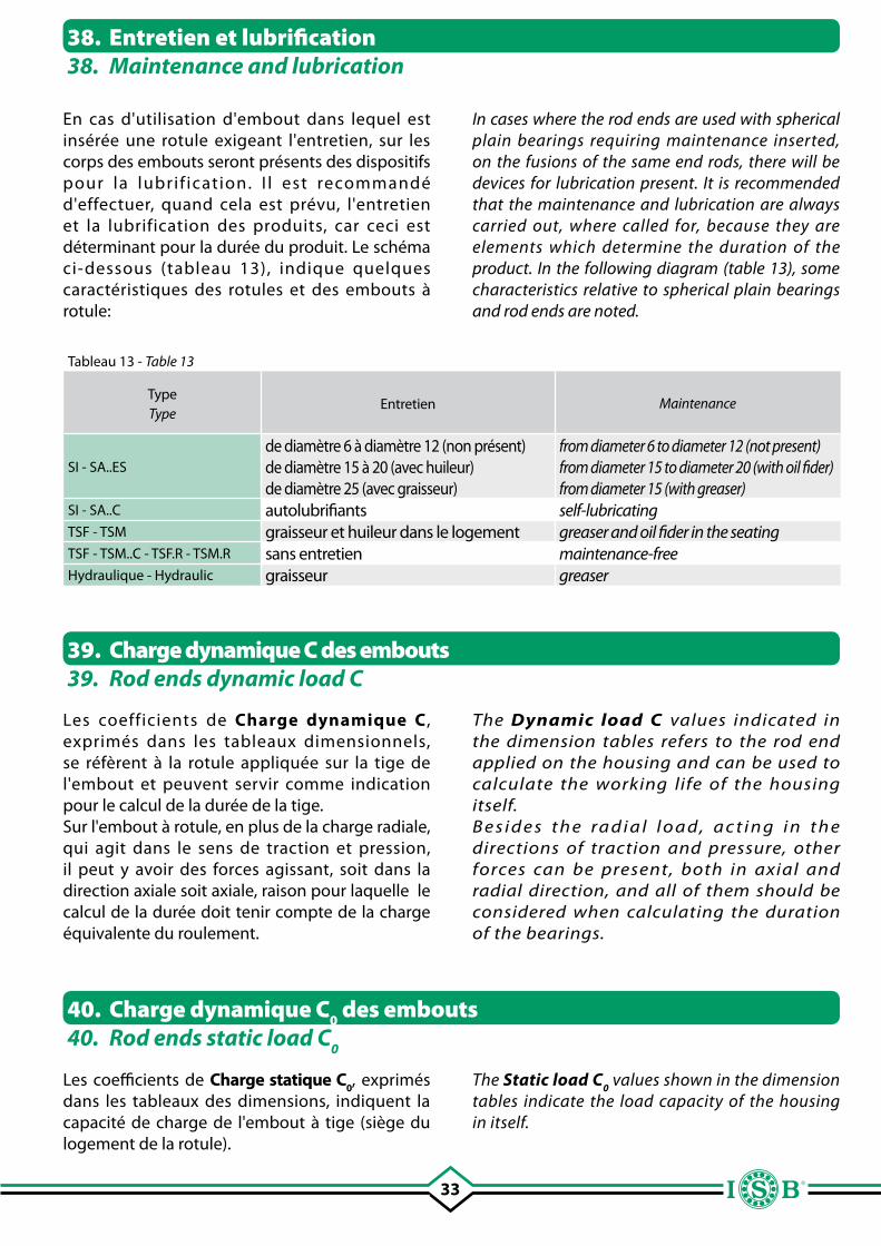
33
38. Entretien et lubrification38. Maintenance and lubrication
En cas d'utilisation d'embout dans lequel est insérée une rotule exigeant l'entretien, sur les corps des embouts seront présents des dispositifs pour la lubrif ication. I l est recommandé d'effectuer, quand cela est prévu, l'entretien et la lubrification des produits, car ceci est déterminant pour la durée du produit. Le schéma ci-dessous (tableau 13), indique quelques caractéristiques des rotules et des embouts à rotule:
Tableau 13 - Table 13
TypeType
Entretien Maintenance
SI - SA..ESde diamètre 6 à diamètre 12 (non présent)de diamètre 15 à 20 (avec huileur) de diamètre 25 (avec graisseur)
from diameter 6 to diameter 12 (not present)from diameter 15 to diameter 20 (with oil fider) from diameter 15 (with greaser)
SI - SA..C autolubrifiants self-lubricatingTSF - TSM graisseur et huileur dans le logement greaser and oil fider in the seatingTSF - TSM..C - TSF.R - TSM.R sans entretien maintenance-freeHydraulique - Hydraulic graisseur greaser
39. Charge dynamique C des embouts39. Rod ends dynamic load C
Les coefficients de Charge dynamique C , exprimés dans les tableaux dimensionnels, se réfèrent à la rotule appliquée sur la tige de l'embout et peuvent servir comme indication pour le calcul de la durée de la tige. Sur l'embout à rotule, en plus de la charge radiale, qui agit dans le sens de traction et pression, il peut y avoir des forces agissant, soit dans la direction axiale soit axiale, raison pour laquelle le calcul de la durée doit tenir compte de la charge équivalente du roulement.
Les coefficients de Charge statique C0, exprimés dans les tableaux des dimensions, indiquent la capacité de charge de l'embout à tige (siège du logement de la rotule).
40. Charge dynamique C0 des embouts40. Rod ends static load C
0
In cases where the rod ends are used with spherical plain bearings requiring maintenance inserted, on the fusions of the same end rods, there will be devices for lubrication present. It is recommended that the maintenance and lubrication are always carried out, where called for, because they are elements which determine the duration of the product. In the following diagram (table 13), some characteristics relative to spherical plain bearings and rod ends are noted.
The Dynamic load C values indicated in the dimension tables refers to the rod end applied on the housing and can be used to calculate the working life of the housing itself.B e s i d e s t h e ra d i a l l o a d, a c t i n g i n t h e directions of traction and pressure, other forces can be present, both in axial and radial direction, and all of them should be considered when calculating the duration of the bearings.
The Static load C0 values shown in the dimension
tables indicate the load capacity of the housing in itself.
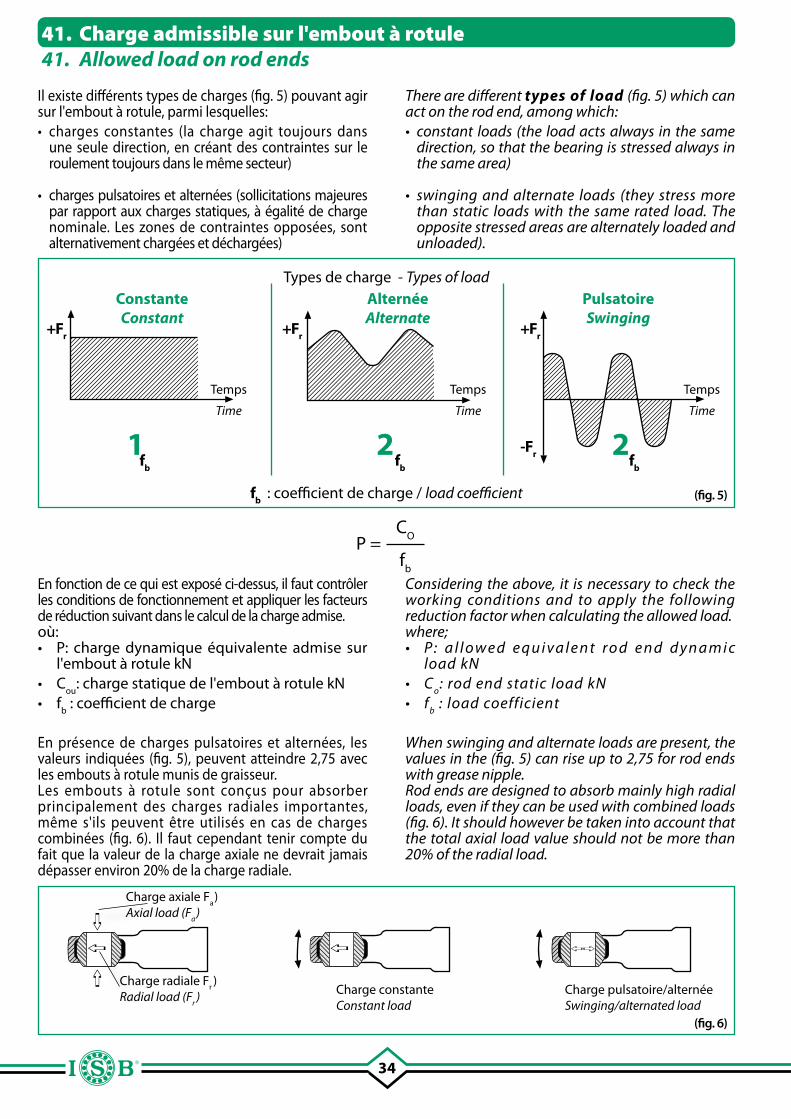
34
Types de charge - Types of loadConstanteConstant
AlternéeAlternate
PulsatoireSwinging
Temps
Time
Temps
Time
Temps
Time
+Fr +Fr +Fr
-Fr
fb : coefficient de charge / load coefficient
1 2 2(fig. 5)
P = C
O
fb
En fonction de ce qui est exposé ci-dessus, il faut contrôler les conditions de fonctionnement et appliquer les facteurs de réduction suivant dans le calcul de la charge admise.où:• P: charge dynamique équivalente admise sur
l'embout à rotule kN• C
ou: charge statique de l'embout à rotule kN
• fb : coefficient de charge
En présence de charges pulsatoires et alternées, les valeurs indiquées (fig. 5), peuvent atteindre 2,75 avec les embouts à rotule munis de graisseur.Les embouts à rotule sont conçus pour absorber principalement des charges radiales importantes, même s'ils peuvent être utilisés en cas de charges combinées (fig. 6). Il faut cependant tenir compte du fait que la valeur de la charge axiale ne devrait jamais dépasser environ 20% de la charge radiale.
fb fb fb
Charge axiale Fa)
Axial load (Fa)
(fig. 6)
Charge radiale Fr)
Radial load (Fr) Charge constante
Constant loadCharge pulsatoire/alternéeSwinging/alternated load
41. Charge admissible sur l'embout à rotule41. Allowed load on rod ends
Il existe différents types de charges (fig. 5) pouvant agir sur l'embout à rotule, parmi lesquelles:• charges constantes (la charge agit toujours dans
une seule direction, en créant des contraintes sur le roulement toujours dans le même secteur)
• charges pulsatoires et alternées (sollicitations majeures par rapport aux charges statiques, à égalité de charge nominale. Les zones de contraintes opposées, sont alternativement chargées et déchargées)
Considering the above, it is necessary to check the working conditions and to apply the following reduction factor when calculating the allowed load.where;• P : a l l o w e d e q u i va l e n t r o d e n d d y n a m i c
load kN• C
o: rod end static load kN
• fb : load coefficient
When swinging and alternate loads are present, the values in the (fig. 5) can rise up to 2,75 for rod ends with grease nipple.Rod ends are designed to absorb mainly high radial loads, even if they can be used with combined loads (fig. 6). It should however be taken into account that the total axial load value should not be more than 20% of the radial load.
There are different types of load (fig. 5) which can act on the rod end, among which:• constant loads (the load acts always in the same
direction, so that the bearing is stressed always in the same area)
• swinging and alternate loads (they stress more than static loads with the same rated load. The opposite stressed areas are alternately loaded and unloaded).
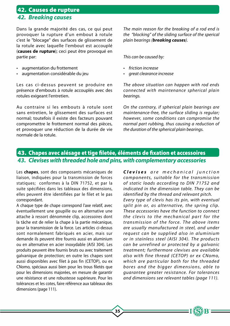
35
42. Causes de rupture42. Breaking causes
Dans la grande majorité des cas, ce qui peut provoquer la rupture d'un embout à rotule c'est le "blocage" des surfaces de glissement de la rotule avec laquelle l'embout est accouplé (causes de rupture); ceci peut être provoqué en partie par:
• augmentation du frottement • augmentation considérable du jeu
Les cas ci-dessus peuvent se produire en présence d'embouts à rotule accouplés avec des rotules exigeant l'entretien.
Au contraire si les embouts à rotule sont sans entretien, le glissement des surfaces est normal; toutefois il existe des facteurs pouvant compromettre le frottement normal des pièces, et provoquer une réduction de la durée de vie normale de la rotule.
43. Chapes avec alésage et tige filetée, éléments de fixation et accessoires43. Clevises with threaded hole and pins, with complementary accessories
Les chapes, sont des composants mécaniques de liaison, indiquées pour la transmission de forces statiques; conformes à la DIN 71752, et par la suite spécifiées dans les tableaux des dimensions, elles peuvent être identifiées par le filet et le pas correspondant. A chaque type de chape correspond l'axe relatif, avec éventuellement une goupille ou en alternative une attache à ressort dénommée clip, accessoires dont la tâche est de relier la chape à la partie mécanique, pour la transmission de la force. Les articles ci-dessus sont normalement fabriqués en acier, mais sur demande ils peuvent être fournis aussi en aluminium ou en alternative en acier inoxydable (AISI 304). Les produits peuvent être fournis bruts ou avec traitement galvanique de protection; en outre les chapes sont aussi disponibles avec filet à pas fin (CETOP), ou ex CNomo, spéciaux aussi bien pour les trous filetés que pour les dimensions majorées, en mesure de garantir une résistance et une robustesse supérieure. Pour les tolérances et les cotes, faire référence aux tableaux des dimensions (page 111).
C l e v i s e s a r e m e c h a n i c a l j u n c t i o n components, suitable for the transmission of static loads according to DIN 71752 and indicated in the dimension table. They can be identified by the thread and relevant pitch. Every type of clevis has its pin, with eventual split pin or, as alternative, the spring cl ip. These accessories have the function to connect t h e c l e v i s t o t h e m e c h a n i ca l p a r t f o r t h e transmission of the force. The above items are usually manufactured in steel, and under request can be supplied also in aluminium or in stainless steel (AISI 304). The products can be unrefined or protected by a galvanic treatment; furthermore clevises are available also with fine thread (CETOP) or ex CNomo, which are par ticular both for the threaded b o re s a n d t h e b i g g e r d i m e n s i o n s, a b l e t o guarantee greater resistance. For tolerances and dimensions see relevant tables (page 111).
The main reason for the breaking of a rod end is the “blocking” of the sliding surface of the sperical plain bearings (breaking causes).
This can be caused by:
• friction increase• great clearance increase
The above situation can happen with rod ends connected with maintenance spherical plain bearings.
On the contrary, if spherical plain bearings are maintenance-free, the surface sliding is regular; however, some conditions can compromise the normal part rubbing, thus causing a reduction of the duration of the spherical plain bearings.
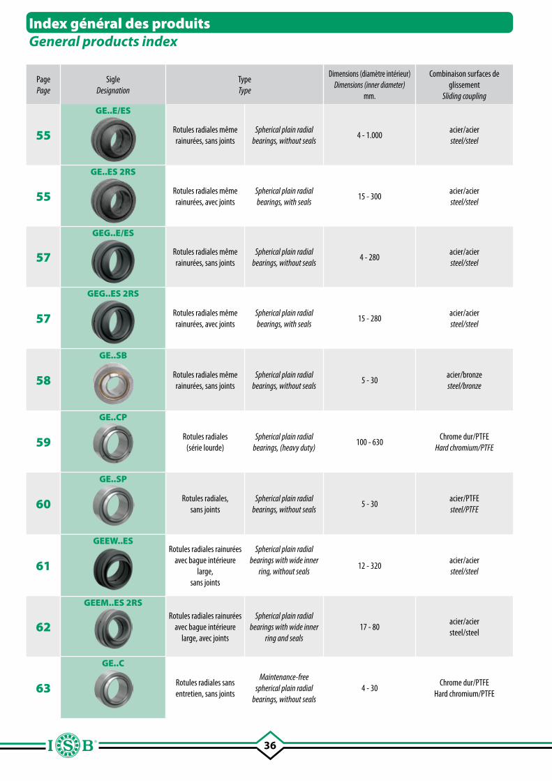
36
Index général des produitsGeneral products index
Page Page
SigleDesignation
TypeType
Dimensions (diamètre intérieur) Dimensions (inner diameter)
mm.
Combinaison surfaces de glissement
Sliding coupling
Lubrification Lubrication
Température °C Temperature °C
Caractéristiques techniques et principaux domaines d'applicationTechnical details and main application fields
55
GE..E/ES
Rotules radiales même rainurées, sans joints
Spherical plain radial bearings, without seals
4 - 1.000acier/acier steel/steel
OuiYes
-60 ~ +200
Bague extérieure et bague intérieure trempées avec rainure sur la bague extérieure et trou de lubrification, version avec et sans joints. Particulièrement indiquées en conditions de fonctionnement à charges élevées alternées et charges de choc; applications appropriées pour machine de construction, vérins hydrauliques, secteur véhicules de transport routier et naval.Hardened outer and inner ring, with groove on outer ring and lubrication hole, with or without seals. Particularly suitable for working with high alternate loads and impact loads; suitable for building machinery, hydraulic cylinders, vehicles for road and naval transport.
55
GE..ES 2RS
Rotules radiales même rainurées, avec joints
Spherical plain radial bearings, with seals
15 - 300acier/acier steel/steel
OuiYes
-60 ~ +130
57
GEG..E/ES
Rotules radiales même rainurées, sans joints
Spherical plain radial bearings, without seals
4 - 280acier/acier steel/steel
OuiYes
-60 ~ +200
La bague intérieure majorée, permet un meilleur angle de basculement α. Les caractéristiques techniques et les principaux domaines d'application sont équivalents au type GE.The oversize inner ring allows a wider turnover angle α. Technical characteristics and main applications are the same as for GE type.
57
GEG..ES 2RS
Rotules radiales même rainurées, avec joints
Spherical plain radial bearings, with seals
15 - 280acier/acier steel/steel
OuiYes
-60 ~ +130
58
GE..SB
Rotules radiales même rainurées, sans joints
Spherical plain radial bearings, without seals
5 - 30acier/bronze steel/bronze
OuiYes
-60 ~ +250
Bague extérieure profilée sur la bague intérieure Particulièrement indiquées à être utilisées sur machines d'emballage, machine à imprimer, machines de transport et tri.Outer ring shaped on inner ring. Particularly suitable for packing machinery, printing machinery, conveyor and sorting machinery.
59
GE..CP
Rotules radiales(série lourde)
Spherical plain radial bearings, (heavy duty)
100 - 630Chrome dur/PTFE
Hard chromium/PTFENon -50 ~ +130
Bague intérieure trempée, bague extérieure pas trempée, fendue radialement et fixée par vis de blocage. Particulièrement indiquées pour la construction de machines lourdes, équipements de levage, grues, ponts roulant.Hardened inner ring, outer ring not hardened, radial cut and tightened with a blocking screws. Particularly suitable for building heavy vehicles, lifting equipments, cranes, bridge cranes.
60
GE..SP
Rotules radiales,sans joints
Spherical plain radial bearings, without seals
5 - 30acier/PTFE steel/PTFE
Non -50 ~ +200
Bague extérieure profilée sur la bague intérieure Particulièrement indiquées à être utilisées sur machines d'emballage, machine à imprimer, appareils de levage.Outer ring shaped on inner ring. Particularly suitable for packing machinery, printing machinery, lifting devices.
61
GEEW..ESRotules radiales rainurées
avec bague intérieure large,
sans joints
Spherical plain radial bearings with wide inner
ring, without seals12 - 320
acier/aciersteel/steel
OuiYes
-60 ~ +200
Bague intérieure et extérieure trempées. Une fente axiale est présente sur la bague extérieure pour le montage de la bague intérieure. Fabrication conforme DIN 24338, particulièrement indiquées pour la liaison de pistons et cylindres normalisés.Hardened inner and outer ring. The outer ring has an axial rift for inner ring mounting. Manufactured according to DIN 24338, and particularly suitable for coupling pistons and standardized cylinders.
62
GEEM..ES 2RSRotules radiales rainurées
avec bague intérieure large, avec joints
Spherical plain radial bearings with wide inner
ring and seals17 - 80
acier/acier steel/steel
OuiYes
-60 ~ +130
Les caractéristiques techniques et les principaux domaines d'application sont équivalents au type GE. Elles se différencient par des prolongements cylindriques particuliers sur la bague intérieure, qui permet le montage en évitant l'application d'entretoises, entre les épaulements.Main technical characteristics and application fields are equivalent to the GE type. However, they are different for the presence of special cylindrical extensions on the inner ring, which allow the assembling without using spacer rings between shoulders.
63
GE..C
Rotules radiales sans entretien, sans joints
Maintenance-free spherical plain radial
bearings, without seals4 - 30
Chrome dur/PTFEHard chromium/PTFE
Non -50 ~ +200
Bague intérieure trempée, bague extérieure constituée d'une partie extérieure en acier et une partie intérieure avec fibre textile PTFE qui glisse sur la bague intérieure. Particulièrement indiquées en conditions normales de fonctionnement pour pistons de vérins hydrauliques, équipements de levage en général.Hardened inner ring, outer ring formed by an external steel part and an internal PTFE part. In normal working conditions they are particularly suitable for hydraulic cylinders pistons of and lifting equipment.
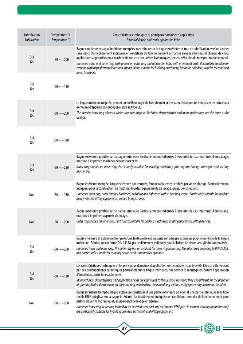
37
Page Page
SigleDesignation
TypeType
Dimensions (diamètre intérieur) Dimensions (inner diameter)
mm.
Combinaison surfaces de glissement
Sliding coupling
Lubrification Lubrication
Température °C Temperature °C
Caractéristiques techniques et principaux domaines d'applicationTechnical details and main application fields
55
GE..E/ES
Rotules radiales même rainurées, sans joints
Spherical plain radial bearings, without seals
4 - 1.000acier/acier steel/steel
OuiYes
-60 ~ +200
Bague extérieure et bague intérieure trempées avec rainure sur la bague extérieure et trou de lubrification, version avec et sans joints. Particulièrement indiquées en conditions de fonctionnement à charges élevées alternées et charges de choc; applications appropriées pour machine de construction, vérins hydrauliques, secteur véhicules de transport routier et naval.Hardened outer and inner ring, with groove on outer ring and lubrication hole, with or without seals. Particularly suitable for working with high alternate loads and impact loads; suitable for building machinery, hydraulic cylinders, vehicles for road and naval transport.
55
GE..ES 2RS
Rotules radiales même rainurées, avec joints
Spherical plain radial bearings, with seals
15 - 300acier/acier steel/steel
OuiYes
-60 ~ +130
57
GEG..E/ES
Rotules radiales même rainurées, sans joints
Spherical plain radial bearings, without seals
4 - 280acier/acier steel/steel
OuiYes
-60 ~ +200
La bague intérieure majorée, permet un meilleur angle de basculement α. Les caractéristiques techniques et les principaux domaines d'application sont équivalents au type GE.The oversize inner ring allows a wider turnover angle α. Technical characteristics and main applications are the same as for GE type.
57
GEG..ES 2RS
Rotules radiales même rainurées, avec joints
Spherical plain radial bearings, with seals
15 - 280acier/acier steel/steel
OuiYes
-60 ~ +130
58
GE..SB
Rotules radiales même rainurées, sans joints
Spherical plain radial bearings, without seals
5 - 30acier/bronze steel/bronze
OuiYes
-60 ~ +250
Bague extérieure profilée sur la bague intérieure Particulièrement indiquées à être utilisées sur machines d'emballage, machine à imprimer, machines de transport et tri.Outer ring shaped on inner ring. Particularly suitable for packing machinery, printing machinery, conveyor and sorting machinery.
59
GE..CP
Rotules radiales(série lourde)
Spherical plain radial bearings, (heavy duty)
100 - 630Chrome dur/PTFE
Hard chromium/PTFENon -50 ~ +130
Bague intérieure trempée, bague extérieure pas trempée, fendue radialement et fixée par vis de blocage. Particulièrement indiquées pour la construction de machines lourdes, équipements de levage, grues, ponts roulant.Hardened inner ring, outer ring not hardened, radial cut and tightened with a blocking screws. Particularly suitable for building heavy vehicles, lifting equipments, cranes, bridge cranes.
60
GE..SP
Rotules radiales,sans joints
Spherical plain radial bearings, without seals
5 - 30acier/PTFE steel/PTFE
Non -50 ~ +200
Bague extérieure profilée sur la bague intérieure Particulièrement indiquées à être utilisées sur machines d'emballage, machine à imprimer, appareils de levage.Outer ring shaped on inner ring. Particularly suitable for packing machinery, printing machinery, lifting devices.
61
GEEW..ESRotules radiales rainurées
avec bague intérieure large,
sans joints
Spherical plain radial bearings with wide inner
ring, without seals12 - 320
acier/aciersteel/steel
OuiYes
-60 ~ +200
Bague intérieure et extérieure trempées. Une fente axiale est présente sur la bague extérieure pour le montage de la bague intérieure. Fabrication conforme DIN 24338, particulièrement indiquées pour la liaison de pistons et cylindres normalisés.Hardened inner and outer ring. The outer ring has an axial rift for inner ring mounting. Manufactured according to DIN 24338, and particularly suitable for coupling pistons and standardized cylinders.
62
GEEM..ES 2RSRotules radiales rainurées
avec bague intérieure large, avec joints
Spherical plain radial bearings with wide inner
ring and seals17 - 80
acier/acier steel/steel
OuiYes
-60 ~ +130
Les caractéristiques techniques et les principaux domaines d'application sont équivalents au type GE. Elles se différencient par des prolongements cylindriques particuliers sur la bague intérieure, qui permet le montage en évitant l'application d'entretoises, entre les épaulements.Main technical characteristics and application fields are equivalent to the GE type. However, they are different for the presence of special cylindrical extensions on the inner ring, which allow the assembling without using spacer rings between shoulders.
63
GE..C
Rotules radiales sans entretien, sans joints
Maintenance-free spherical plain radial
bearings, without seals4 - 30
Chrome dur/PTFEHard chromium/PTFE
Non -50 ~ +200
Bague intérieure trempée, bague extérieure constituée d'une partie extérieure en acier et une partie intérieure avec fibre textile PTFE qui glisse sur la bague intérieure. Particulièrement indiquées en conditions normales de fonctionnement pour pistons de vérins hydrauliques, équipements de levage en général.Hardened inner ring, outer ring formed by an external steel part and an internal PTFE part. In normal working conditions they are particularly suitable for hydraulic cylinders pistons of and lifting equipment.
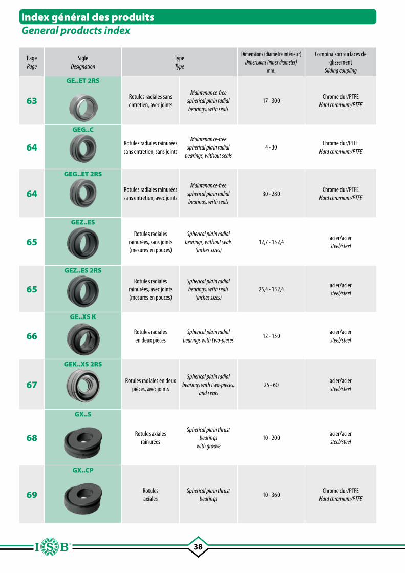
38
Page Page
SigleDesignation
TypeType
Dimensions (diamètre intérieur) Dimensions (inner diameter)
mm.
Combinaison surfaces de glissement
Sliding coupling
Lubrification Lubrication
Température °C Temperature °C
Caractéristiques techniques et principaux domaines d'applicationTechnical details and main application fields
63
GE..ET 2RS
Rotules radiales sans entretien, avec joints
Maintenance-free spherical plain radial bearings, with seals
17 - 300Chrome dur/PTFE
Hard chromium/PTFENon -50 ~ +130
Bague intérieure et extérieure trempées. Bague extérieure avec fente axiale pour le montage (jusqu'au diamètre 120 mm.); pour les diamètres supérieurs, la bague extérieure est divisée axialement et fixée par des bagues. Les caractéristiques techniques et les principaux domaines d'application sont équivalents au type GE...C, mais avec de meilleures performances.Hardened inner and outer ring. An axial rift for assemblying is present on the outer ring (up to diameter 120 mm.); for bigger diameters the external ring is splitted and blocked by rings. The technical characteristics and application fields are equivalent to the GE..C type, but with better performances.
64
GEG..C
Rotules radiales rainurées sans entretien, sans joints
Maintenance-free spherical plain radial
bearings, without seals4 - 30
Chrome dur/PTFEHard chromium/PTFE
Non -50 ~ +200
Les caractéristiques techniques et les principaux domaines d'applications sont équivalents au type GE..C. Elle se différencient toutefois par la bague intérieure majorée, qui permet un plus grand angle de basculement α..The main technical characteristics and application fields are equivalent to the GE C. type. However, they are different for the bigger inner ring, which allows a wider turnover angle α.
64
GEG..ET 2RS
Rotules radiales rainurées sans entretien, avec joints
Maintenance-free spherical plain radial bearings, with seals
30 - 280Chrome dur/PTFE
Hard chromium/PTFENon -50 ~ +130
Les caractéristiques techniques et les principaux domaines d'application sont équivalents au type GE..ET 2RS. Elles se différencient toutefois par la bague intérieure majorée, qui permet un meilleur angle de basculement α.The main technical characteristics and application fields are equivalent to the GE..ET 2RS type. However, they are different for the bigger inner ring, which allows a wider turnover angle α.
65
GEZ..ES
Rotules radiales rainurées, sans joints (mesures en pouces)
Spherical plain radial bearings, without seals
(inches sizes)12,7 - 152,4
acier/acier steel/steel
OuiYes
-60 ~ +200
Les caractéristiques techniques et les principaux domaines d'application sont équivalents au type GE. Elles se différencient par l'utilisation dans des applications exigeant des produits avec mesures en pouces.The technical characteristics and the main application fields are equivalent to the GE type. They are however different for the use in application where inches measures are required.
65
GEZ..ES 2RS
Rotules radiales rainurées, avec joints (mesures en pouces)
Spherical plain radial bearings, with seals
(inches sizes)25,4 - 152,4
acier/acier steel/steel
OuiYes
-60 ~ +130
66
GE..XS K
Rotules radialesen deux pièces
Spherical plain radial bearings with two-pieces
12 - 150acier/acier steel/steel
OuiYes
-60 ~ +200
Bague extérieure en deux pièces axiales. Rainure et trou de lubrification sur la bague intérieure et extérieure Rotule traitée par phosphatation-bondérisation.Outer ring with two-pieces in axial direction. Lubrication groove and hole in the outer and inner ring. Joint is bonderized and phosphorlylate-treated.
67
GEK..XS 2RS
Rotules radiales en deux pièces, avec joints
Spherical plain radial bearings with two-pieces,
and seals25 - 60
acier/acier steel/steel
OuiYes
-60 ~ +130
Bague extérieure en deux pièces et deux schémas, bille interne en acier chromé avec rainure et trou de lubrification.Outer ring with two axial pieces and two seals. Inner sphere is chrome steel plates with lubrication groove and hole.
68
GX..S
Rotules axialesrainurées
Spherical plain thrust bearings
with groove10 - 200
acier/acier steel/steel
OuiYes
-60 ~ +200
Couronne de l'arbre et du logement trempées et toutes deux séparables l'une de l'autre; elles peuvent être combinées directement avec des rotules radiales. Elles ont une rainure et un trou de lubrification sur la couronne de logement. Elles représentent une alternative valable aux roulements à rouleaux coniques de la série 320..; adaptées à supporter des forces axiales et radiales, dans les mouvements de réglage elles sont sujettes à une charge unidirectionnelle. Shaft and housing fifth wheel both hardened and separable, they can be joined directly with spherical radial bearings. They have groove and lubrication hole on the fifth wheel. They represent an alternative for taper roller bearing of the series 320..; they can bear axial and radial loads, in the adjustment movement are subject only to unidirectional load.
69
GX..CP
Rotules axiales
Spherical plain thrust bearings
10 - 360Chrome dur/PTFE
Hard chromium/PTFENon -50 ~ +150
Les caractéristiques techniques et les principaux domaines d'application sont équivalents au type GX...S. Particulièrement indiquées en présence de mouvements minimum, mais avec fortes charges. La couronne pour logement à partir du diamètre 160 mm n'est pas trempée.The technical characteristics and applications fields are equivalent to the GAC..S type. They are particularly suitable in case of minimum movements and heavy loads. The fifth wheel starting from diameter 160 mm is not hardened.
Index général des produitsGeneral products index
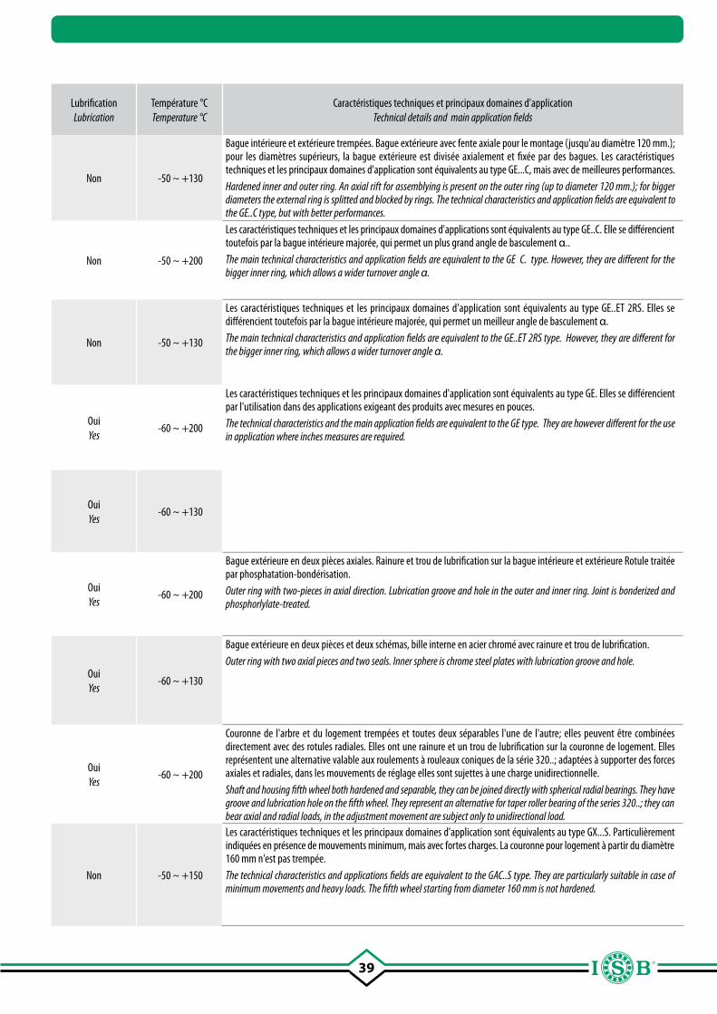
39
Page Page
SigleDesignation
TypeType
Dimensions (diamètre intérieur) Dimensions (inner diameter)
mm.
Combinaison surfaces de glissement
Sliding coupling
Lubrification Lubrication
Température °C Temperature °C
Caractéristiques techniques et principaux domaines d'applicationTechnical details and main application fields
63
GE..ET 2RS
Rotules radiales sans entretien, avec joints
Maintenance-free spherical plain radial bearings, with seals
17 - 300Chrome dur/PTFE
Hard chromium/PTFENon -50 ~ +130
Bague intérieure et extérieure trempées. Bague extérieure avec fente axiale pour le montage (jusqu'au diamètre 120 mm.); pour les diamètres supérieurs, la bague extérieure est divisée axialement et fixée par des bagues. Les caractéristiques techniques et les principaux domaines d'application sont équivalents au type GE...C, mais avec de meilleures performances.Hardened inner and outer ring. An axial rift for assemblying is present on the outer ring (up to diameter 120 mm.); for bigger diameters the external ring is splitted and blocked by rings. The technical characteristics and application fields are equivalent to the GE..C type, but with better performances.
64
GEG..C
Rotules radiales rainurées sans entretien, sans joints
Maintenance-free spherical plain radial
bearings, without seals4 - 30
Chrome dur/PTFEHard chromium/PTFE
Non -50 ~ +200
Les caractéristiques techniques et les principaux domaines d'applications sont équivalents au type GE..C. Elle se différencient toutefois par la bague intérieure majorée, qui permet un plus grand angle de basculement α..The main technical characteristics and application fields are equivalent to the GE C. type. However, they are different for the bigger inner ring, which allows a wider turnover angle α.
64
GEG..ET 2RS
Rotules radiales rainurées sans entretien, avec joints
Maintenance-free spherical plain radial bearings, with seals
30 - 280Chrome dur/PTFE
Hard chromium/PTFENon -50 ~ +130
Les caractéristiques techniques et les principaux domaines d'application sont équivalents au type GE..ET 2RS. Elles se différencient toutefois par la bague intérieure majorée, qui permet un meilleur angle de basculement α.The main technical characteristics and application fields are equivalent to the GE..ET 2RS type. However, they are different for the bigger inner ring, which allows a wider turnover angle α.
65
GEZ..ES
Rotules radiales rainurées, sans joints (mesures en pouces)
Spherical plain radial bearings, without seals
(inches sizes)12,7 - 152,4
acier/acier steel/steel
OuiYes
-60 ~ +200
Les caractéristiques techniques et les principaux domaines d'application sont équivalents au type GE. Elles se différencient par l'utilisation dans des applications exigeant des produits avec mesures en pouces.The technical characteristics and the main application fields are equivalent to the GE type. They are however different for the use in application where inches measures are required.
65
GEZ..ES 2RS
Rotules radiales rainurées, avec joints (mesures en pouces)
Spherical plain radial bearings, with seals
(inches sizes)25,4 - 152,4
acier/acier steel/steel
OuiYes
-60 ~ +130
66
GE..XS K
Rotules radialesen deux pièces
Spherical plain radial bearings with two-pieces
12 - 150acier/acier steel/steel
OuiYes
-60 ~ +200
Bague extérieure en deux pièces axiales. Rainure et trou de lubrification sur la bague intérieure et extérieure Rotule traitée par phosphatation-bondérisation.Outer ring with two-pieces in axial direction. Lubrication groove and hole in the outer and inner ring. Joint is bonderized and phosphorlylate-treated.
67
GEK..XS 2RS
Rotules radiales en deux pièces, avec joints
Spherical plain radial bearings with two-pieces,
and seals25 - 60
acier/acier steel/steel
OuiYes
-60 ~ +130
Bague extérieure en deux pièces et deux schémas, bille interne en acier chromé avec rainure et trou de lubrification.Outer ring with two axial pieces and two seals. Inner sphere is chrome steel plates with lubrication groove and hole.
68
GX..S
Rotules axialesrainurées
Spherical plain thrust bearings
with groove10 - 200
acier/acier steel/steel
OuiYes
-60 ~ +200
Couronne de l'arbre et du logement trempées et toutes deux séparables l'une de l'autre; elles peuvent être combinées directement avec des rotules radiales. Elles ont une rainure et un trou de lubrification sur la couronne de logement. Elles représentent une alternative valable aux roulements à rouleaux coniques de la série 320..; adaptées à supporter des forces axiales et radiales, dans les mouvements de réglage elles sont sujettes à une charge unidirectionnelle. Shaft and housing fifth wheel both hardened and separable, they can be joined directly with spherical radial bearings. They have groove and lubrication hole on the fifth wheel. They represent an alternative for taper roller bearing of the series 320..; they can bear axial and radial loads, in the adjustment movement are subject only to unidirectional load.
69
GX..CP
Rotules axiales
Spherical plain thrust bearings
10 - 360Chrome dur/PTFE
Hard chromium/PTFENon -50 ~ +150
Les caractéristiques techniques et les principaux domaines d'application sont équivalents au type GX...S. Particulièrement indiquées en présence de mouvements minimum, mais avec fortes charges. La couronne pour logement à partir du diamètre 160 mm n'est pas trempée.The technical characteristics and applications fields are equivalent to the GAC..S type. They are particularly suitable in case of minimum movements and heavy loads. The fifth wheel starting from diameter 160 mm is not hardened.
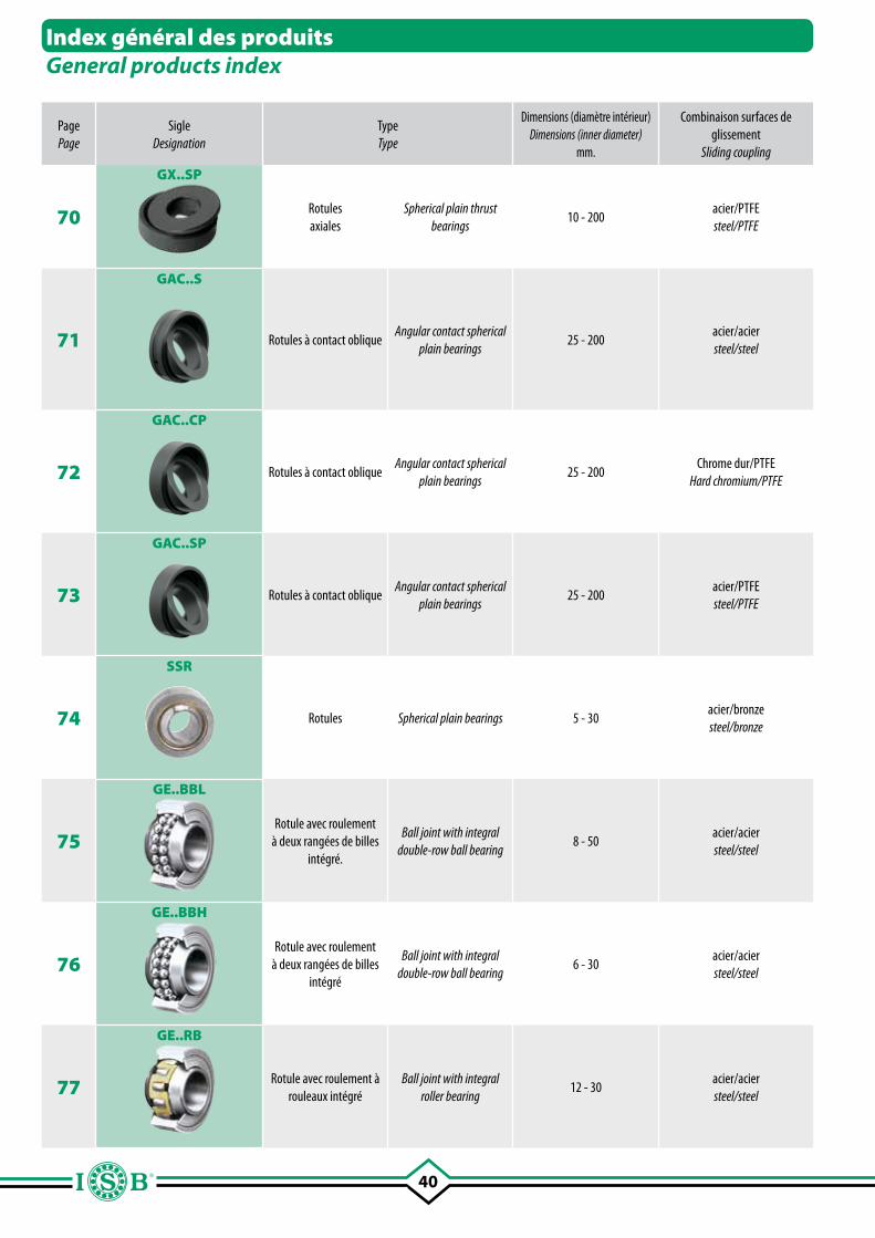
40
Page Page
SigleDesignation
TypeType
Dimensions (diamètre intérieur) Dimensions (inner diameter)
mm.
Combinaison surfaces de glissement
Sliding coupling
Lubrification Lubrication
Température °C Temperature °C
Caractéristiques techniques et principaux domaines d'applicationTechnical details and main application fields
70
GX..SP
Rotules axiales
Spherical plain thrust bearings
10 - 200acier/PTFE steel/PTFE
Non -40 ~ +150
Les caractéristiques techniques et les principaux domaines d'application sont équivalents au type GX..S et GX..CP. Combinées à des rotules radiales, elles peuvent supporter des charges radiales et axiales dans les deux sens. The technical characteristics and the main application fields are equivalent to the GX..S e GX..CP types. In case they are combined with plain radial bearings, they can bear radial and axial loads in both directions.
71
GAC..S
Rotules à contact oblique Angular contact spherical
plain bearings25 - 200
acier/acier steel/steel
OuiYes
-60 ~ +200
Bague intérieure et extérieure complètement séparables et trempées; considérées comme l'alternative aux roulements à rouleaux coniques. Elles ont une rainure et un trou de lubrification sur la bague extérieure. Adaptées par leur forme aux charges dynamiques changeantes et au cas où les charges de choc, associées à de petits angles d'oscillation produisent des dégâts. Particulièrement indiqués pour les supports à charnière élastique, essieux de remorques, en général dans le secteur des transports.Inner and outer ring are both hardened and completely separable; they can be considered as an alternative to taper roller bearing. They have grooves and lubrication hole on the outer ring. Due to their shape they are suitable in case of dynamic loads or when impact loads, together with little oscillation angles, should cause damages. They are particularly suitable for elastic inge support, trailers’ axle and general in the transport field.
72
GAC..CP
Rotules à contact oblique Angular contact spherical
plain bearings25 - 200
Chrome dur/PTFEHard chromium/PTFE
Non -50 ~ +150
Les caractéristiques techniques et les principaux domaines d'application sont équivalents au type GAC.S. Particulièrement indiquées en présence de mouvements minimum, mais avec fortes charges.The technical characteristics and applications fields are equivalent to GAC..S. type. Particularly suitable in case of minimum movements and heavy loads.
73
GAC..SP
Rotules à contact oblique Angular contact spherical
plain bearings25 - 200
acier/PTFEsteel/PTFE
Non -40 ~ +150
Les caractéristiques techniques et les principaux domaines d'application sont équivalents au type GAC..S et GAC..CP. Si utilisées par paire, elles peuvent supporter des charges axiales dans les deux sens. The technical characteristics and application fields can be considered equivalent to the GAC...S and GAC...CP types. When used paired, they can bear axial loads in both directions.
74
SSR
Rotules Spherical plain bearings 5 - 30acier/bronze steel/bronze
OuiYes
-60 ~ +250
Bague extérieure avec rainure circonférentielle, avec trou de lubrification. Les caractéristiques techniques et les principaux domaines d'application sont équivalents au type GE..SB Outer ring with circumference groove and lubrication hole. The technical characteristics and the main application fields are equivalent to the GE...SB type.
75
GE..BBL
Rotule avec roulement à deux rangées de billes
intégré.
Ball joint with integral double-row ball bearing
8 - 50acier/acier steel/steel
OuiYes
-45 ~ +120
Bague extérieure: acier 100 Cr 6; trempé, rectifié, avec joints. Bague intérieure: acier 100 Cr 6; trempé, rectifié. Lubrification: graisse pour roulements haute vitesse.Jeu radial: 10 ÷ 30 µm.Outer ring: 100 Cr 6 steel; hardened, superfinished, with seals.Inner ring: 100 Cr 6 steel; hardened, superfinished.Lubrication: high speed bearing grease (temp. range -45° to +120°).Radial clearance: 10 ÷ 30 µm.
76
GE..BBH
Rotule avec roulement à deux rangées de billes
intégré
Ball joint with integral double-row ball bearing
6 - 30acier/acier steel/steel
OuiYes
-45 ~ +120
Bague extérieure: acier 100 Cr 6; trempé, rectifié, avec flasques protecteurs. Bague intérieure: acier 100 Cr 6; trempé, rectifié. Lubrification: graisse pour roulements haute vitesse.Jeu radial: 10 ÷ 30 µm.Outer ring: 100 Cr 6 steel; hardened, superfinished, with shields.Inner ring: 100 Cr 6 steel; hardened, superfinished.Lubrication: high speed bearing grease (temp. range -45° to +120°).Radial clearance: 10 ÷ 30 µm.
77
GE..RB
Rotule avec roulement à rouleaux intégré
Ball joint with integral roller bearing
12 - 30acier/acier steel/steel
OuiYes
-45 ~ +120
Bague extérieure: acier 100 Cr 6; trempé, rectifié, avec flasques protecteurs. Bague intérieure: acier 100 Cr 6; trempé, rectifié. Lubrification: graisse pour roulements haute vitesse.Jeu radial: 10 ÷ 30 µm.Outer ring: 100 Cr 6 steel; hardened, superfinished, with shields.Inner ring: 100 Cr 6 steel; hardened, superfinished.Lubrication: high speed bearing grease (temp. range -45° to +120°).Radial clearance: 10 ÷ 30 µm.
Index général des produitsGeneral products index
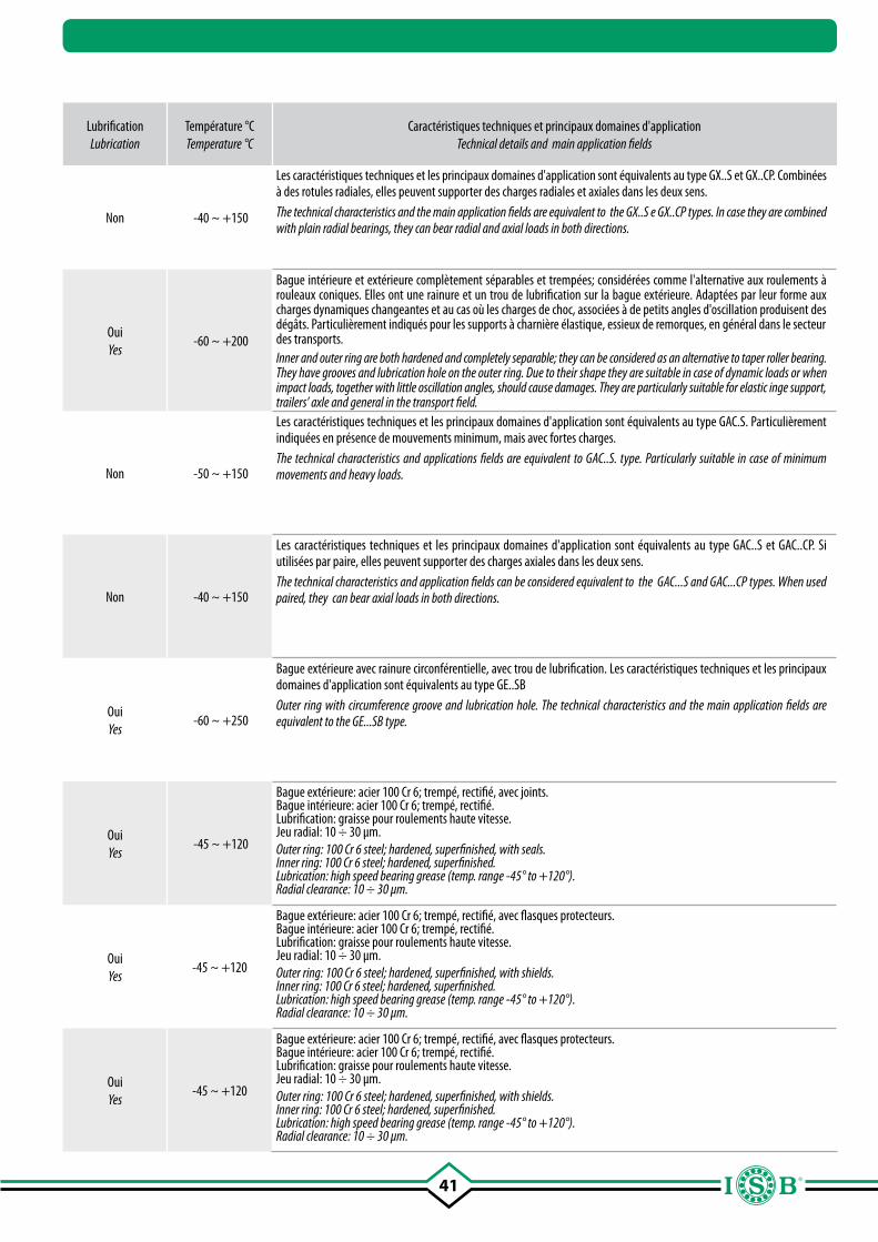
41
Page Page
SigleDesignation
TypeType
Dimensions (diamètre intérieur) Dimensions (inner diameter)
mm.
Combinaison surfaces de glissement
Sliding coupling
Lubrification Lubrication
Température °C Temperature °C
Caractéristiques techniques et principaux domaines d'applicationTechnical details and main application fields
70
GX..SP
Rotules axiales
Spherical plain thrust bearings
10 - 200acier/PTFE steel/PTFE
Non -40 ~ +150
Les caractéristiques techniques et les principaux domaines d'application sont équivalents au type GX..S et GX..CP. Combinées à des rotules radiales, elles peuvent supporter des charges radiales et axiales dans les deux sens. The technical characteristics and the main application fields are equivalent to the GX..S e GX..CP types. In case they are combined with plain radial bearings, they can bear radial and axial loads in both directions.
71
GAC..S
Rotules à contact oblique Angular contact spherical
plain bearings25 - 200
acier/acier steel/steel
OuiYes
-60 ~ +200
Bague intérieure et extérieure complètement séparables et trempées; considérées comme l'alternative aux roulements à rouleaux coniques. Elles ont une rainure et un trou de lubrification sur la bague extérieure. Adaptées par leur forme aux charges dynamiques changeantes et au cas où les charges de choc, associées à de petits angles d'oscillation produisent des dégâts. Particulièrement indiqués pour les supports à charnière élastique, essieux de remorques, en général dans le secteur des transports.Inner and outer ring are both hardened and completely separable; they can be considered as an alternative to taper roller bearing. They have grooves and lubrication hole on the outer ring. Due to their shape they are suitable in case of dynamic loads or when impact loads, together with little oscillation angles, should cause damages. They are particularly suitable for elastic inge support, trailers’ axle and general in the transport field.
72
GAC..CP
Rotules à contact oblique Angular contact spherical
plain bearings25 - 200
Chrome dur/PTFEHard chromium/PTFE
Non -50 ~ +150
Les caractéristiques techniques et les principaux domaines d'application sont équivalents au type GAC.S. Particulièrement indiquées en présence de mouvements minimum, mais avec fortes charges.The technical characteristics and applications fields are equivalent to GAC..S. type. Particularly suitable in case of minimum movements and heavy loads.
73
GAC..SP
Rotules à contact oblique Angular contact spherical
plain bearings25 - 200
acier/PTFEsteel/PTFE
Non -40 ~ +150
Les caractéristiques techniques et les principaux domaines d'application sont équivalents au type GAC..S et GAC..CP. Si utilisées par paire, elles peuvent supporter des charges axiales dans les deux sens. The technical characteristics and application fields can be considered equivalent to the GAC...S and GAC...CP types. When used paired, they can bear axial loads in both directions.
74
SSR
Rotules Spherical plain bearings 5 - 30acier/bronze steel/bronze
OuiYes
-60 ~ +250
Bague extérieure avec rainure circonférentielle, avec trou de lubrification. Les caractéristiques techniques et les principaux domaines d'application sont équivalents au type GE..SB Outer ring with circumference groove and lubrication hole. The technical characteristics and the main application fields are equivalent to the GE...SB type.
75
GE..BBL
Rotule avec roulement à deux rangées de billes
intégré.
Ball joint with integral double-row ball bearing
8 - 50acier/acier steel/steel
OuiYes
-45 ~ +120
Bague extérieure: acier 100 Cr 6; trempé, rectifié, avec joints. Bague intérieure: acier 100 Cr 6; trempé, rectifié. Lubrification: graisse pour roulements haute vitesse.Jeu radial: 10 ÷ 30 µm.Outer ring: 100 Cr 6 steel; hardened, superfinished, with seals.Inner ring: 100 Cr 6 steel; hardened, superfinished.Lubrication: high speed bearing grease (temp. range -45° to +120°).Radial clearance: 10 ÷ 30 µm.
76
GE..BBH
Rotule avec roulement à deux rangées de billes
intégré
Ball joint with integral double-row ball bearing
6 - 30acier/acier steel/steel
OuiYes
-45 ~ +120
Bague extérieure: acier 100 Cr 6; trempé, rectifié, avec flasques protecteurs. Bague intérieure: acier 100 Cr 6; trempé, rectifié. Lubrification: graisse pour roulements haute vitesse.Jeu radial: 10 ÷ 30 µm.Outer ring: 100 Cr 6 steel; hardened, superfinished, with shields.Inner ring: 100 Cr 6 steel; hardened, superfinished.Lubrication: high speed bearing grease (temp. range -45° to +120°).Radial clearance: 10 ÷ 30 µm.
77
GE..RB
Rotule avec roulement à rouleaux intégré
Ball joint with integral roller bearing
12 - 30acier/acier steel/steel
OuiYes
-45 ~ +120
Bague extérieure: acier 100 Cr 6; trempé, rectifié, avec flasques protecteurs. Bague intérieure: acier 100 Cr 6; trempé, rectifié. Lubrification: graisse pour roulements haute vitesse.Jeu radial: 10 ÷ 30 µm.Outer ring: 100 Cr 6 steel; hardened, superfinished, with shields.Inner ring: 100 Cr 6 steel; hardened, superfinished.Lubrication: high speed bearing grease (temp. range -45° to +120°).Radial clearance: 10 ÷ 30 µm.
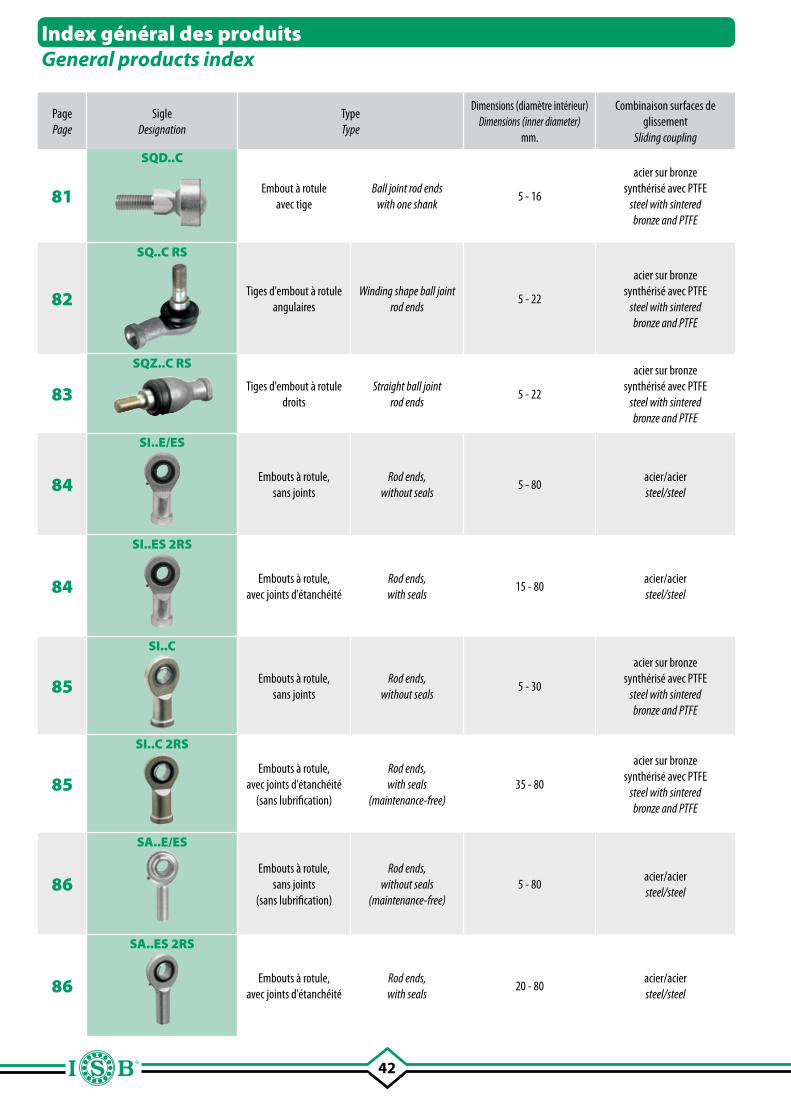
42
Page Page
SigleDesignation
TypeType
Dimensions (diamètre intérieur) Dimensions (inner diameter)
mm.
Combinaison surfaces de glissement
Sliding coupling
Lubrification Lubrication
Température °C Temperature °C
Caractéristiques techniques et principaux domaines d'applicationTechnical details and main application fields
81
SQD..C
Embout à rotule avec tige
Ball joint rod endswith one shank
5 - 16
acier sur bronze synthérisé avec PTFE
steel with sinteredbronze and PTFE
Non -50 ~ +130
Rotule radiale avec bille interne à tige filetée. Indiqué dans les applications qui exigent un auto-alignement entre la bague extérieure et le siège du logement.Radial spherical plain bearing with internal ball and threaded rod. It is suitable in application which require self-aligning between the outer ring and the housing.
82
SQ..C RS
Tiges d'embout à rotule angulaires
Winding shape ball joint rod ends
5 - 22
acier sur bronze synthérisé avec PTFE
steel with sinteredbronze and PTFE
Non -50 ~ +130
Tige d'embout à rotule en forme de “L” avec joint anti-poussière. Particulièrement indiqués pour être utilisés sur des organes en mouvement, directions, essieux, quand est nécessaire un auto-alignement.Ball joint bearing “L” shaped with dust cover. Particularly suitable to be used on moving parts, steering, axles whereas self-alignig is necessary.
83
SQZ..C RS
Tiges d'embout à rotule droits
Straight ball joint rod ends
5 - 22
acier sur bronze synthérisé avec PTFE
steel with sinteredbronze and PTFE
Non -50 ~ +130
Les caractéristiques techniques et les principaux domaines d'application sont équivalents au type SQ..C RS, mais la forme change car elle est droite.The technical characteristics and the main application field are equivalent to the SQ..C RS type, the only difference is the shape which is straight.
84
SI..E/ES
Embouts à rotule, sans joints
Rod ends, without seals
5 - 80acier/aciersteel/steel
OuiYes
-
Embouts à rotule fabriqués en acier C45 (zingué) conforme aux normes DIN 648 série E. Le filetage de réglage, se trouve dans la partie interne de la tige et il est très long. La rotule exige un entretien, au moyen d'un graisseur sur le corps de fonderie ou par un trou dans le logement. Particulièrement indiqués pour des fonctionnements avec charges élevées, alternées et de choc. Peuvent être fournis avec joints d'étanchéité 2RS.Rod ends manufactured in steel C45 (zinc plated) according to regulation DIN 648 series E. The registration thread is located in the internal part of the shank and it is very long. The spherical rod end need to be lubricated with a grease nipple on the housing or a lubrication hole. They are particularly suitable in presence of high alternate and impact loads. They can be supplied with seals 2RS.
84
SI..ES 2RS
Embouts à rotule, avec joints d'étanchéité
Rod ends, with seals
15 - 80acier/aciersteel/steel
OuiYes
-
85
SI..C
Embouts à rotule, sans joints
Rod ends, without seals
5 - 30
acier sur bronze synthérisé avec PTFE
steel with sinteredbronze and PTFE
Non -
Embouts à rotule fabriqués en acier C45 (zingué) conforme aux normes DIN 648 série E. Le filetage de réglage, se trouve dans la partie interne de la tige et il est très long. La rotule n'exige pas d'entretien. Particulièrement indiqués pour des fonctionnements avec charges unilatérales constantes et mouvements lents. Peuvent être fournis avec joints d'étanchéité 2RS.Rod ends manufactured in steel C45 (zinc plated) according to regulation DIN 648 series E. The registration thread is located in the internal part of the shank and it is very long. The rod end is maintenance-free. They are particularly suitable in presence of steady unilateral loads and slow movements. They can be supplied with seals 2RS.
85
SI..C 2RS
Embouts à rotule, avec joints d'étanchéité
(sans lubrification)
Rod ends, with seals
(maintenance-free)35 - 80
acier sur bronze synthérisé avec PTFE
steel with sinteredbronze and PTFE
Non -
86
SA..E/ES
Embouts à rotule, sans joints
(sans lubrification)
Rod ends, without seals
(maintenance-free)5 - 80
acier/aciersteel/steel
OuiYes
-
Embouts à rotule fabriqués en acier C45 (zingué) conforme aux normes DIN 648 série E. Le filetage de réglage, se trouve dans la partie extérieure de la tige et il est très long. La rotule exige un entretien, au moyen d'un graisseur sur le corps de fonderie ou par un trou dans le logement. Particulièrement indiqués pour des fonctionnements avec charges élevées, alternées et de choc. Peuvent être fournis avec joints d'étanchéité 2RS.Rod ends manufactured in steel C45 (zinc plated) according to regulation DIN 648 series E. The registration thread is located in the internal part of the shank and it is very long. The rod end needs to be lubricated with a grease nipple on the housing or a lubrication hole. They are particularly suitable in presence of high alternate and impact loads. They can be supplied with seals 2RS.
86
SA..ES 2RS
Embouts à rotule, avec joints d'étanchéité
Rod ends, with seals
20 - 80acier/aciersteel/steel
OuiYes
-
Index général des produitsGeneral products index
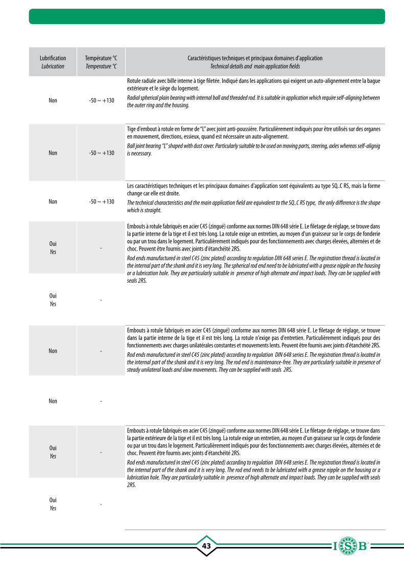
43
Page Page
SigleDesignation
TypeType
Dimensions (diamètre intérieur) Dimensions (inner diameter)
mm.
Combinaison surfaces de glissement
Sliding coupling
Lubrification Lubrication
Température °C Temperature °C
Caractéristiques techniques et principaux domaines d'applicationTechnical details and main application fields
81
SQD..C
Embout à rotule avec tige
Ball joint rod endswith one shank
5 - 16
acier sur bronze synthérisé avec PTFE
steel with sinteredbronze and PTFE
Non -50 ~ +130
Rotule radiale avec bille interne à tige filetée. Indiqué dans les applications qui exigent un auto-alignement entre la bague extérieure et le siège du logement.Radial spherical plain bearing with internal ball and threaded rod. It is suitable in application which require self-aligning between the outer ring and the housing.
82
SQ..C RS
Tiges d'embout à rotule angulaires
Winding shape ball joint rod ends
5 - 22
acier sur bronze synthérisé avec PTFE
steel with sinteredbronze and PTFE
Non -50 ~ +130
Tige d'embout à rotule en forme de “L” avec joint anti-poussière. Particulièrement indiqués pour être utilisés sur des organes en mouvement, directions, essieux, quand est nécessaire un auto-alignement.Ball joint bearing “L” shaped with dust cover. Particularly suitable to be used on moving parts, steering, axles whereas self-alignig is necessary.
83
SQZ..C RS
Tiges d'embout à rotule droits
Straight ball joint rod ends
5 - 22
acier sur bronze synthérisé avec PTFE
steel with sinteredbronze and PTFE
Non -50 ~ +130
Les caractéristiques techniques et les principaux domaines d'application sont équivalents au type SQ..C RS, mais la forme change car elle est droite.The technical characteristics and the main application field are equivalent to the SQ..C RS type, the only difference is the shape which is straight.
84
SI..E/ES
Embouts à rotule, sans joints
Rod ends, without seals
5 - 80acier/aciersteel/steel
OuiYes
-
Embouts à rotule fabriqués en acier C45 (zingué) conforme aux normes DIN 648 série E. Le filetage de réglage, se trouve dans la partie interne de la tige et il est très long. La rotule exige un entretien, au moyen d'un graisseur sur le corps de fonderie ou par un trou dans le logement. Particulièrement indiqués pour des fonctionnements avec charges élevées, alternées et de choc. Peuvent être fournis avec joints d'étanchéité 2RS.Rod ends manufactured in steel C45 (zinc plated) according to regulation DIN 648 series E. The registration thread is located in the internal part of the shank and it is very long. The spherical rod end need to be lubricated with a grease nipple on the housing or a lubrication hole. They are particularly suitable in presence of high alternate and impact loads. They can be supplied with seals 2RS.
84
SI..ES 2RS
Embouts à rotule, avec joints d'étanchéité
Rod ends, with seals
15 - 80acier/aciersteel/steel
OuiYes
-
85
SI..C
Embouts à rotule, sans joints
Rod ends, without seals
5 - 30
acier sur bronze synthérisé avec PTFE
steel with sinteredbronze and PTFE
Non -
Embouts à rotule fabriqués en acier C45 (zingué) conforme aux normes DIN 648 série E. Le filetage de réglage, se trouve dans la partie interne de la tige et il est très long. La rotule n'exige pas d'entretien. Particulièrement indiqués pour des fonctionnements avec charges unilatérales constantes et mouvements lents. Peuvent être fournis avec joints d'étanchéité 2RS.Rod ends manufactured in steel C45 (zinc plated) according to regulation DIN 648 series E. The registration thread is located in the internal part of the shank and it is very long. The rod end is maintenance-free. They are particularly suitable in presence of steady unilateral loads and slow movements. They can be supplied with seals 2RS.
85
SI..C 2RS
Embouts à rotule, avec joints d'étanchéité
(sans lubrification)
Rod ends, with seals
(maintenance-free)35 - 80
acier sur bronze synthérisé avec PTFE
steel with sinteredbronze and PTFE
Non -
86
SA..E/ES
Embouts à rotule, sans joints
(sans lubrification)
Rod ends, without seals
(maintenance-free)5 - 80
acier/aciersteel/steel
OuiYes
-
Embouts à rotule fabriqués en acier C45 (zingué) conforme aux normes DIN 648 série E. Le filetage de réglage, se trouve dans la partie extérieure de la tige et il est très long. La rotule exige un entretien, au moyen d'un graisseur sur le corps de fonderie ou par un trou dans le logement. Particulièrement indiqués pour des fonctionnements avec charges élevées, alternées et de choc. Peuvent être fournis avec joints d'étanchéité 2RS.Rod ends manufactured in steel C45 (zinc plated) according to regulation DIN 648 series E. The registration thread is located in the internal part of the shank and it is very long. The rod end needs to be lubricated with a grease nipple on the housing or a lubrication hole. They are particularly suitable in presence of high alternate and impact loads. They can be supplied with seals 2RS.
86
SA..ES 2RS
Embouts à rotule, avec joints d'étanchéité
Rod ends, with seals
20 - 80acier/aciersteel/steel
OuiYes
-
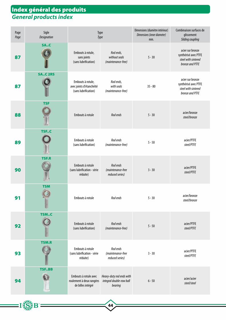
44
Page Page
SigleDesignation
TypeType
Dimensions (diamètre intérieur) Dimensions (inner diameter)
mm.
Combinaison surfaces de glissement
Sliding coupling
Lubrification Lubrication
Température °C Temperature °C
Caractéristiques techniques et principaux domaines d'applicationTechnical details and main application fields
87
SA..C
Embouts à rotule, sans joints
(sans lubrification)
Rod ends, without seals
(maintenance-free)5 - 30
acier sur bronze synthérisé avec PTFE
steel with sinteredbronze and PTFE
Non -
Embouts à rotule fabriqués en acier C45 (zingué) conforme aux normes DIN 648 série E. Le filetage de réglage, se trouve dans la partie extérieure de la tige et il est très long. La rotule n'exige pas d'entretien. Particulièrement indiqués pour des fonctionnements avec charges unilatérales constantes et mouvements lents. Peuvent être fournis avec joints d'étanchéité 2RS.Rod ends manufactured in steel C45 (zinc plated) according to regulation DIN 648 series E. The registration thread is located in the internal part of the shank and it is very long. The rod end is maintenance-free. They are particularly suitable in presence of steady and unilateral loads. They can be supplied with seals 2RS.
87
SA..C 2RS
Embouts à rotule, avec joints d'étanchéité
(sans lubrification)
Rod ends, with seals
(maintenance-free)35 - 80
acier sur bronze synthérisé avec PTFE
steel with sinteredbronze and PTFE
Non -
88
TSF
Embouts à rotule Rod ends 5 - 30acier/bronze steel/bronze
OuiYes
-
Embouts à rotule fabriqués en acier C45 (zingué) conforme aux normes DIN 648 série K. Le filetage de réglage, se trouve dans la partie interne de la tige et il est très long. La rotule exige un entretien, au moyen d'un graisseur à entonnoir sur le corps de fonderie ou par un trou dans le logement. Particulièrement indiqués pour des emplois universels (charges alternées - unilatérales, mouvements lents de rotation, angles d'oscillation moyens-grands). Indiqués aussi à l'accouplement sur dispositifs de mouvement et chaînes de transmission du mouvement. Disponibles aussi avec filet CETOP 1). Rod end manufactured in steel C45 (zinc plated) according to the regulation DIN 648 series K. The registration thread is located in the internal part of the shank and it is very long. The spherical rod end needs to be lubricated with a funnel on the housings or a lubrication hole (for series TSF). They are particularly suitable for universal applications (alternate and unilateral loads - slow rotation movements, medium to wide oscillation angles). They are also suitable for joining movement devices and transmission chains. Available also with CETOP 1) thread.89
TSF..C
Embouts à rotule(sans lubrification)
Rod ends(maintenance-free)
5 - 50acier/PTFE steel/PTFE
Non -
90
TSF.R
Embouts à rotule(sans lubrification - série
réduite)
Rod ends(maintenance-free
reduced series)3 - 30
acier/PTFE steel/PTFE
Non -
91
TSM
Embouts à rotule Rod ends 5 - 30acier/bronze steel/bronze
OuiYes
-
Embouts à rotule fabriqués en acier C45 (zingué) conforme aux normes DIN 648 série K. Le filetage de réglage, se trouve dans la partie extérieure de la tige et il est très long. La rotule exige un entretien, au moyen d'un graisseur à entonnoir sur le corps de fonderie ou par un trou dans le logement (pour la série TSM). Particulièrement indiqués pour des emplois universels (charges alternées - unilatérales, mouvements lents de rotation, angles d'oscillation moyens-grands). Indiqués aussi à l'accouplement sur dispositifs de mouvement et chaînes de transmission du mouvement. Disponibles aussi avec filet CETOP 1). Rod end manufactured in steel C45 (zinc plated) according to the regulation DIN 648 series K. The registration thread is located in the internal part of the shank and it is very long. The spherical rod end needs to be lubricated with a funnel on the housings or a lubrication hole (for series TSM). They are particularly suitable for universal applications (alternate and unilateral loads - slow rotation movements, medium to wide oscillation angles). They are suitable also for joining movement devices and transmission chains. Available also with CETOP 1) thread.92
TSM..C
Embouts à rotule(sans lubrification)
Rod ends(maintenance-free)
5 - 50acier/PTFE steel/PTFE
Non -
93
TSM.R
Embouts à rotule(sans lubrification - série
réduite)
Rod ends(maintenance-free
reduced series)3 - 30
acier/PTFE steel/PTFE
Non -
94
TSF..BB
Embouts à rotule avec roulement à deux rangées
de billes intégré
Heavy-duty rod ends with integral double-row ball
bearing6 - 50
acier/acier steel/steel
OuiYes
-45 ~ +120
Corps: acier embouti; chemin de roulement trempé, rectifié, surface zinguée, sans chrome hexavalent. Bague intérieure: acier 100 Cr 6; trempé, rectifié. Lubrification: graisse pour roulements haute vitesse. Température d'utilisation : de -45°C à +120°C. Jeu radial roulement: 10 ÷ 30 µmHousing forged steel case-hardened bearing race superfinished galvanized surface chromium VI free. Inner ring ball bearing steel: (100 Cr 6); hardened, superfinished. Lubrication: high speed bearing grease (temp. range -45° to +120°). Temperature range: -45°C to +120°C. Radial clearance (radial): 10 ÷ 30 µm
Index général des produitsGeneral products index
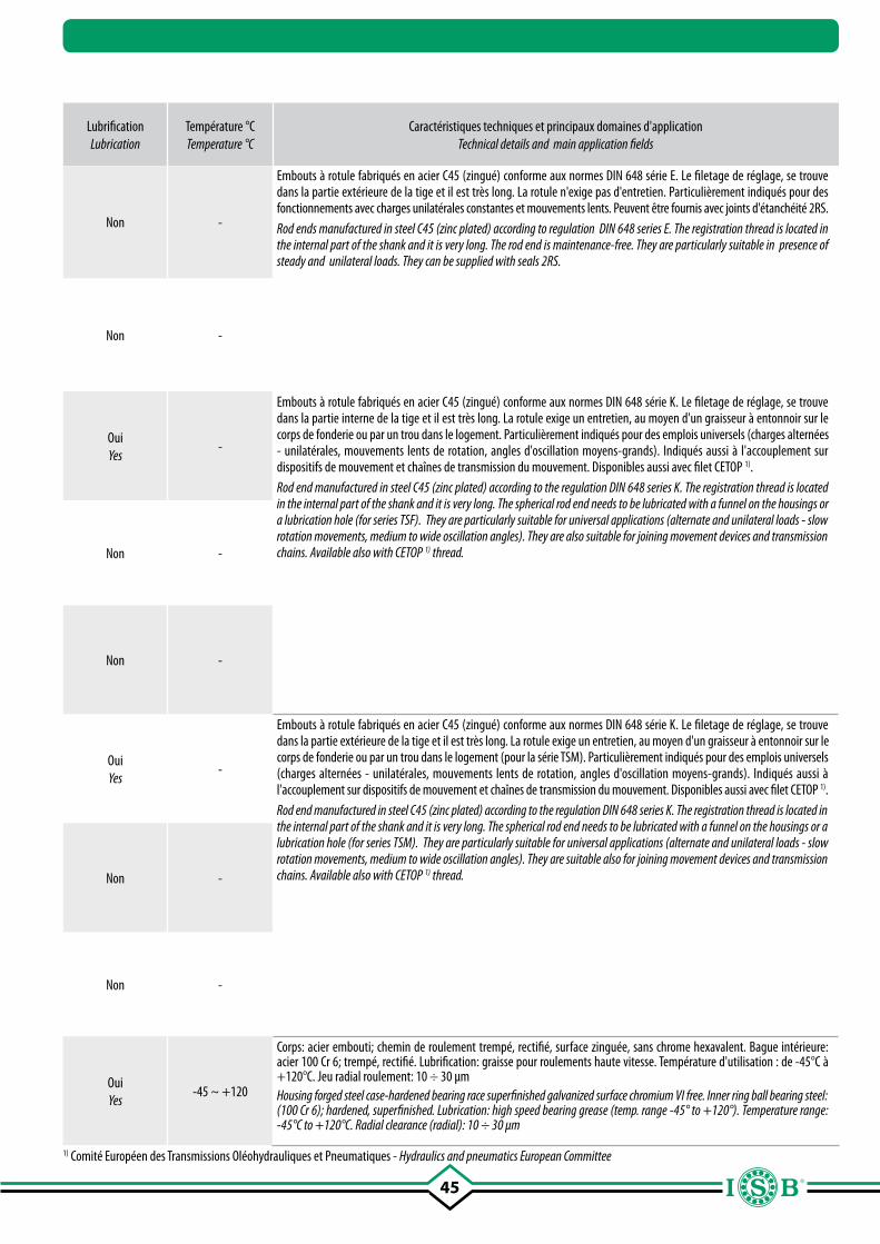
45
Page Page
SigleDesignation
TypeType
Dimensions (diamètre intérieur) Dimensions (inner diameter)
mm.
Combinaison surfaces de glissement
Sliding coupling
Lubrification Lubrication
Température °C Temperature °C
Caractéristiques techniques et principaux domaines d'applicationTechnical details and main application fields
87
SA..C
Embouts à rotule, sans joints
(sans lubrification)
Rod ends, without seals
(maintenance-free)5 - 30
acier sur bronze synthérisé avec PTFE
steel with sinteredbronze and PTFE
Non -
Embouts à rotule fabriqués en acier C45 (zingué) conforme aux normes DIN 648 série E. Le filetage de réglage, se trouve dans la partie extérieure de la tige et il est très long. La rotule n'exige pas d'entretien. Particulièrement indiqués pour des fonctionnements avec charges unilatérales constantes et mouvements lents. Peuvent être fournis avec joints d'étanchéité 2RS.Rod ends manufactured in steel C45 (zinc plated) according to regulation DIN 648 series E. The registration thread is located in the internal part of the shank and it is very long. The rod end is maintenance-free. They are particularly suitable in presence of steady and unilateral loads. They can be supplied with seals 2RS.
87
SA..C 2RS
Embouts à rotule, avec joints d'étanchéité
(sans lubrification)
Rod ends, with seals
(maintenance-free)35 - 80
acier sur bronze synthérisé avec PTFE
steel with sinteredbronze and PTFE
Non -
88
TSF
Embouts à rotule Rod ends 5 - 30acier/bronze steel/bronze
OuiYes
-
Embouts à rotule fabriqués en acier C45 (zingué) conforme aux normes DIN 648 série K. Le filetage de réglage, se trouve dans la partie interne de la tige et il est très long. La rotule exige un entretien, au moyen d'un graisseur à entonnoir sur le corps de fonderie ou par un trou dans le logement. Particulièrement indiqués pour des emplois universels (charges alternées - unilatérales, mouvements lents de rotation, angles d'oscillation moyens-grands). Indiqués aussi à l'accouplement sur dispositifs de mouvement et chaînes de transmission du mouvement. Disponibles aussi avec filet CETOP 1). Rod end manufactured in steel C45 (zinc plated) according to the regulation DIN 648 series K. The registration thread is located in the internal part of the shank and it is very long. The spherical rod end needs to be lubricated with a funnel on the housings or a lubrication hole (for series TSF). They are particularly suitable for universal applications (alternate and unilateral loads - slow rotation movements, medium to wide oscillation angles). They are also suitable for joining movement devices and transmission chains. Available also with CETOP 1) thread.89
TSF..C
Embouts à rotule(sans lubrification)
Rod ends(maintenance-free)
5 - 50acier/PTFE steel/PTFE
Non -
90
TSF.R
Embouts à rotule(sans lubrification - série
réduite)
Rod ends(maintenance-free
reduced series)3 - 30
acier/PTFE steel/PTFE
Non -
91
TSM
Embouts à rotule Rod ends 5 - 30acier/bronze steel/bronze
OuiYes
-
Embouts à rotule fabriqués en acier C45 (zingué) conforme aux normes DIN 648 série K. Le filetage de réglage, se trouve dans la partie extérieure de la tige et il est très long. La rotule exige un entretien, au moyen d'un graisseur à entonnoir sur le corps de fonderie ou par un trou dans le logement (pour la série TSM). Particulièrement indiqués pour des emplois universels (charges alternées - unilatérales, mouvements lents de rotation, angles d'oscillation moyens-grands). Indiqués aussi à l'accouplement sur dispositifs de mouvement et chaînes de transmission du mouvement. Disponibles aussi avec filet CETOP 1). Rod end manufactured in steel C45 (zinc plated) according to the regulation DIN 648 series K. The registration thread is located in the internal part of the shank and it is very long. The spherical rod end needs to be lubricated with a funnel on the housings or a lubrication hole (for series TSM). They are particularly suitable for universal applications (alternate and unilateral loads - slow rotation movements, medium to wide oscillation angles). They are suitable also for joining movement devices and transmission chains. Available also with CETOP 1) thread.92
TSM..C
Embouts à rotule(sans lubrification)
Rod ends(maintenance-free)
5 - 50acier/PTFE steel/PTFE
Non -
93
TSM.R
Embouts à rotule(sans lubrification - série
réduite)
Rod ends(maintenance-free
reduced series)3 - 30
acier/PTFE steel/PTFE
Non -
94
TSF..BB
Embouts à rotule avec roulement à deux rangées
de billes intégré
Heavy-duty rod ends with integral double-row ball
bearing6 - 50
acier/acier steel/steel
OuiYes
-45 ~ +120
Corps: acier embouti; chemin de roulement trempé, rectifié, surface zinguée, sans chrome hexavalent. Bague intérieure: acier 100 Cr 6; trempé, rectifié. Lubrification: graisse pour roulements haute vitesse. Température d'utilisation : de -45°C à +120°C. Jeu radial roulement: 10 ÷ 30 µmHousing forged steel case-hardened bearing race superfinished galvanized surface chromium VI free. Inner ring ball bearing steel: (100 Cr 6); hardened, superfinished. Lubrication: high speed bearing grease (temp. range -45° to +120°). Temperature range: -45°C to +120°C. Radial clearance (radial): 10 ÷ 30 µm
1) Comité Européen des Transmissions Oléohydrauliques et Pneumatiques - Hydraulics and pneumatics European Committee
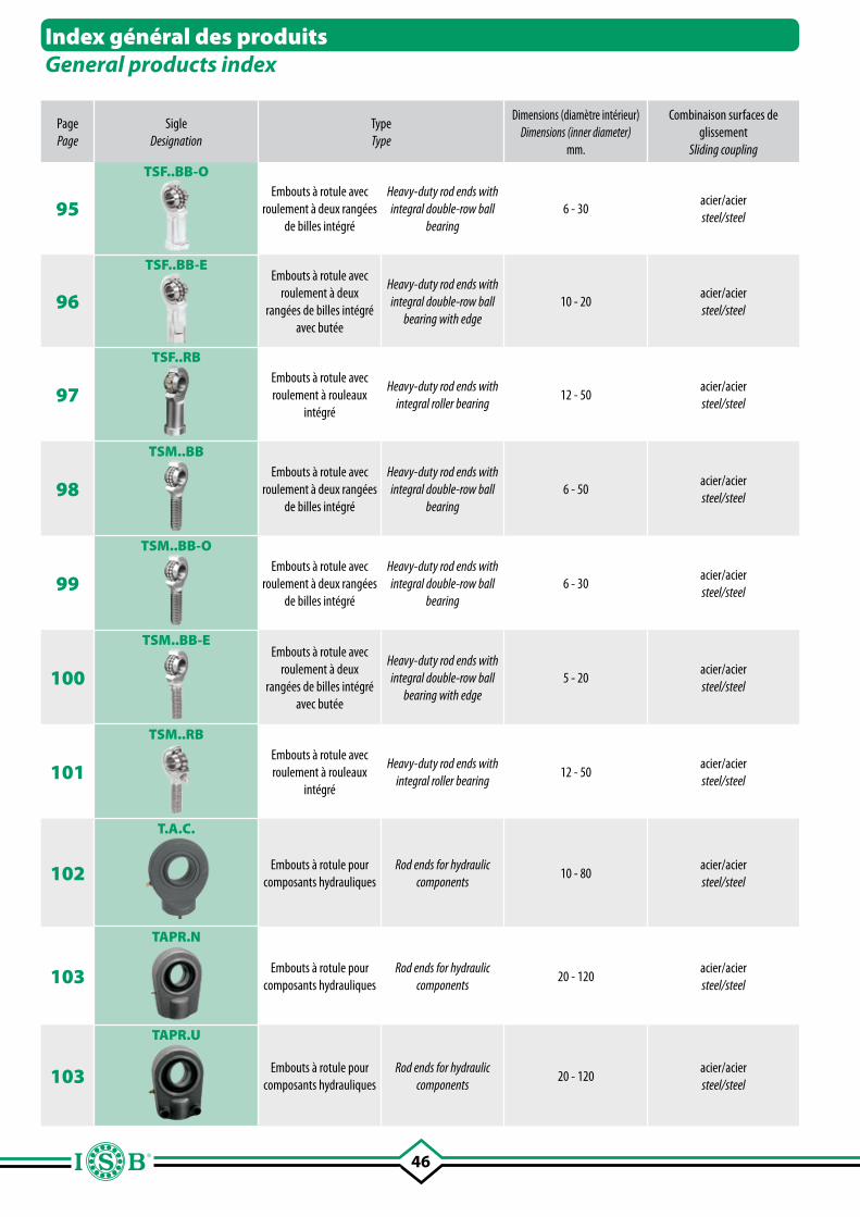
46
Page Page
SigleDesignation
TypeType
Dimensions (diamètre intérieur) Dimensions (inner diameter)
mm.
Combinaison surfaces de glissement
Sliding coupling
Lubrification Lubrication
Température °C Temperature °C
Caractéristiques techniques et principaux domaines d'applicationTechnical details and main application fields
95
TSF..BB-OEmbouts à rotule avec
roulement à deux rangées de billes intégré
Heavy-duty rod ends with integral double-row ball
bearing6 - 30
acier/acier steel/steel
OuiYes
-45 ~ +120
Corps: acier embouti; chemin de roulement trempé, rectifié, surface zinguée, sans chrome hexavalent. Bague intérieure: acier 100 Cr 6; trempé, rectifié. Lubrification: graisse pour roulements haute vitesse. Température d'utilisation : de -45°C à +120°C. Jeu radial roulement: 10 ÷ 30 µm.Housing forged steel case-hardened bearing race superfinished galvanized surface chromium VI free. Inner ring ball bearing steel: (100 Cr 6); hardened, superfinished. Lubrication: high speed bearing grease (temp. range -45° to +120°). Temperature range: -45°C to +120°C. Radial clearance (radial): 10 ÷ 30 µm
96
TSF..BB-EEmbouts à rotule avec
roulement à deux rangées de billes intégré
avec butée
Heavy-duty rod ends with integral double-row ball
bearing with edge10 - 20
acier/acier steel/steel
OuiYes
-45 ~ +120
Corps: acier embouti; chemin de roulement trempé, rectifié, surface zinguée, sans chrome hexavalent. Bague intérieure: acier 100 Cr 6; trempé, rectifié. Lubrification: graisse pour roulements haute vitesse. Température d'utilisation : de -45°C à +120°C. Jeu radial roulement: 10 ÷ 30 µm.Housing forged steel case-hardened bearing race superfinished galvanized surface chromium VI free. Inner ring ball bearing steel: (100 Cr 6); hardened, superfinished. Lubrication: high speed bearing grease (temp. range -45° to +120°). Temperature range: -45°C to +120°C. Radial clearance (radial): 10 ÷ 30 µm
97
TSF..RBEmbouts à rotule avec roulement à rouleaux
intégré
Heavy-duty rod ends with integral roller bearing
12 - 50acier/acier steel/steel
OuiYes
-45 ~ +120
Corps: acier embouti; chemin de roulement trempé, rectifié, surface zinguée, sans chrome hexavalent. Bague intérieure: acier 100 Cr 6; trempé, rectifié. Lubrification: graisse pour roulements haute vitesse. Température d'utilisation : de -45°C à +120°C. Jeu radial roulement: 10 ÷ 30 µm.Housing forged steel case-hardened bearing race superfinished galvanized surface chromium VI free. Inner ring ball bearing steel: (100 Cr 6); hardened, superfinished. Lubrication: high speed bearing grease (temp. range -45° to +120°). Temperature range: -45°C to +120°C. Radial clearance (radial): 10 ÷ 30 µm
98
TSM..BBEmbouts à rotule avec
roulement à deux rangées de billes intégré
Heavy-duty rod ends with integral double-row ball
bearing6 - 50
acier/acier steel/steel
OuiYes
-45 ~ +120
Corps: acier embouti; chemin de roulement trempé, rectifié, filet laminé, surface zinguée, sans chrome hexavalent. Bague intérieure: acier 100 Cr 6; trempé, rectifié. Lubrification: graisse pour roulements haute vitesse. Température d'utilisation : de -45°C à +120°C. Jeu radial roulement: 10 ÷ 30 µm.Housing forged steel case-hardened bearing race superfinished rolled thread galvanized surface chromium VI free. Inner ring ball bearing steel: (100 Cr 6); hardened, superfinished. Lubrication: high speed bearing grease (temp. range -45° to +120°). Temperature range: -45°C to +120°C. Radial clearance (radial): 10 ÷ 30 µm.
99
TSM..BB-OEmbouts à rotule avec
roulement à deux rangées de billes intégré
Heavy-duty rod ends with integral double-row ball
bearing6 - 30
acier/acier steel/steel
OuiYes
-45 ~ +120
Corps: acier embouti; chemin de roulement trempé, rectifié, filet laminé, surface zinguée, sans chrome hexavalent. Bague intérieure: acier 100 Cr 6; trempé, rectifié. Lubrification: graisse pour roulements haute vitesse. Température d'utilisation : de -45°C à +120°C. Jeu radial roulement: 10 ÷ 30 µm.Housing forged steel case-hardened bearing race superfinished rolled thread galvanized surface chromium VI free. Inner ring ball bearing steel: (100 Cr 6); hardened, superfinished. Lubrication: high speed bearing grease (temp. range -45° to +120°). Temperature range: -45°C to +120°C.Radial clearance (radial): 10 ÷ 30 µm.
100
TSM..BB-EEmbouts à rotule avec
roulement à deux rangées de billes intégré
avec butée
Heavy-duty rod ends with integral double-row ball
bearing with edge5 - 20
acier/acier steel/steel
OuiYes
-45 ~ +120
Corps: acier embouti; chemin de roulement trempé, rectifié, filet laminé, surface zinguée, sans chrome hexavalent. Bague intérieure: acier 100 Cr 6; trempé, rectifié. Lubrification: graisse pour roulements haute vitesse. Température d'utilisation : de -45°C à +120°C. Jeu radial roulement: 10 ÷ 30 µm.Housing forged steel case-hardened bearing race superfinished rolled thread galvanized surface chromium VI free. Inner ring ball bearing steel: (100 Cr 6); hardened, superfinished. Lubrication: high speed bearing grease (temp. range -45° to +120°). Temperature range: -45°C to +120°C. Radial clearance (radial): 10 ÷ 30 µm.
101
TSM..RBEmbouts à rotule avec roulement à rouleaux
intégré
Heavy-duty rod ends with integral roller bearing
12 - 50acier/acier steel/steel
OuiYes
-45 ~ +120
Corps: acier embouti; chemin de roulement trempé, rectifié, filet laminé, surface zinguée, sans chrome hexavalent. Bague intérieure: acier 100 Cr 6; trempé, rectifié. Lubrification: graisse pour roulements haute vitesse. Température d'utilisation : de -45°C à +120°C. Jeu radial roulement: 10 ÷ 30 µm.Housing forged steel case-hardened bearing race superfinished rolled thread galvanized surface chromium VI free. Inner ring ball bearing steel: (100 Cr 6); hardened, superfinished. Lubrication: high speed bearing grease (temp. range -45° to +120°). Temperature range: -45°C to +120°C. Radial clearance (radial): 10 ÷ 30 µm
102
T.A.C.
Embouts à rotule pour composants hydrauliques
Rod ends for hydraulic components
10 - 80acier/acier steel/steel
OuiYes
-
Embout à rotule avec surface de soudure circulaire, conforme aux normes DIN 648 série E, forme C. Le corps de fonderie est en acier forgé, avec axe de centrage sur le fond de la tige, chanfrein de soudage à 45° et doté de graisseur pour la lubrification. Particulièrement indiqué dans le secteur hydraulique, applicables à l'extrémité de la tige et sur le fond du vérin. Rod end with circular welding surface, according to DIN 648 series E, shape C. The external housing is made of forged steel, with pin at the bottom of the shank, welding bevel at 45° and with grease nipple for lubrication. Particularly suitable in the hydraulic field, can be applied on the rod and cylinder ends.
103
TAPR.N
Embouts à rotule pour composants hydrauliques
Rod ends for hydraulic components
20 - 120acier/acier steel/steel
OuiYes
-
Embout a rotule pour hydraulique et oléodynamique, à filetage intérieur court, conforme DIN 648 série E. Jusqu'à la dimension 50 mm, le corps extérieur est en acier forgé, à partir du diamètre 60 mm il est en fonte à graphite sphéroïdale; doté de graisseur pour la lubrification. Particulièrement indiqué dans le secteur des vérins oléodynamiques et hydrauliques; la structure particulière permet d'exploiter au maximum la course grâce à des entraxes minimes de fixation. Le type TAPR.U permet de fixer le filetage à l'axe au moyen de dispositifs de blocage.Rod ends for hydraulic and oleodinamic components, with short internal thread according to DIN 648 series E. Up to size 50 mm. the external housing is made of forged steel, starting from size 60 mm. is made of cast iron; it has a grease nipple for lubrication. They are particularly suitable in the field of oleodynamics and hydraulic cylinders, the special structure allows the stroke maximum exploitation due to shortest axel base connection. Type TAPR.U allows to fix the thread to the pin with a blocking system.103
TAPR.U
Embouts à rotule pour composants hydrauliques
Rod ends for hydraulic components
20 - 120acier/acier steel/steel
OuiYes
-
Index général des produitsGeneral products index
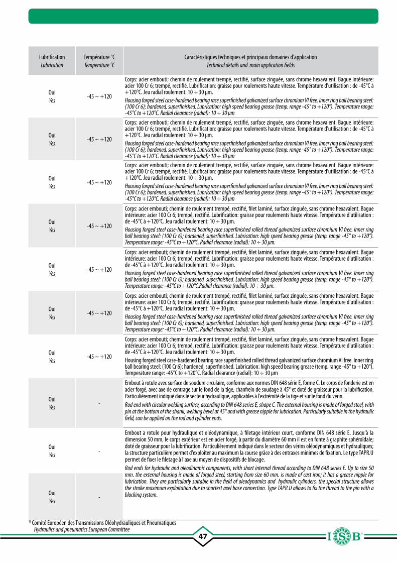
47
Page Page
SigleDesignation
TypeType
Dimensions (diamètre intérieur) Dimensions (inner diameter)
mm.
Combinaison surfaces de glissement
Sliding coupling
Lubrification Lubrication
Température °C Temperature °C
Caractéristiques techniques et principaux domaines d'applicationTechnical details and main application fields
95
TSF..BB-OEmbouts à rotule avec
roulement à deux rangées de billes intégré
Heavy-duty rod ends with integral double-row ball
bearing6 - 30
acier/acier steel/steel
OuiYes
-45 ~ +120
Corps: acier embouti; chemin de roulement trempé, rectifié, surface zinguée, sans chrome hexavalent. Bague intérieure: acier 100 Cr 6; trempé, rectifié. Lubrification: graisse pour roulements haute vitesse. Température d'utilisation : de -45°C à +120°C. Jeu radial roulement: 10 ÷ 30 µm.Housing forged steel case-hardened bearing race superfinished galvanized surface chromium VI free. Inner ring ball bearing steel: (100 Cr 6); hardened, superfinished. Lubrication: high speed bearing grease (temp. range -45° to +120°). Temperature range: -45°C to +120°C. Radial clearance (radial): 10 ÷ 30 µm
96
TSF..BB-EEmbouts à rotule avec
roulement à deux rangées de billes intégré
avec butée
Heavy-duty rod ends with integral double-row ball
bearing with edge10 - 20
acier/acier steel/steel
OuiYes
-45 ~ +120
Corps: acier embouti; chemin de roulement trempé, rectifié, surface zinguée, sans chrome hexavalent. Bague intérieure: acier 100 Cr 6; trempé, rectifié. Lubrification: graisse pour roulements haute vitesse. Température d'utilisation : de -45°C à +120°C. Jeu radial roulement: 10 ÷ 30 µm.Housing forged steel case-hardened bearing race superfinished galvanized surface chromium VI free. Inner ring ball bearing steel: (100 Cr 6); hardened, superfinished. Lubrication: high speed bearing grease (temp. range -45° to +120°). Temperature range: -45°C to +120°C. Radial clearance (radial): 10 ÷ 30 µm
97
TSF..RBEmbouts à rotule avec roulement à rouleaux
intégré
Heavy-duty rod ends with integral roller bearing
12 - 50acier/acier steel/steel
OuiYes
-45 ~ +120
Corps: acier embouti; chemin de roulement trempé, rectifié, surface zinguée, sans chrome hexavalent. Bague intérieure: acier 100 Cr 6; trempé, rectifié. Lubrification: graisse pour roulements haute vitesse. Température d'utilisation : de -45°C à +120°C. Jeu radial roulement: 10 ÷ 30 µm.Housing forged steel case-hardened bearing race superfinished galvanized surface chromium VI free. Inner ring ball bearing steel: (100 Cr 6); hardened, superfinished. Lubrication: high speed bearing grease (temp. range -45° to +120°). Temperature range: -45°C to +120°C. Radial clearance (radial): 10 ÷ 30 µm
98
TSM..BBEmbouts à rotule avec
roulement à deux rangées de billes intégré
Heavy-duty rod ends with integral double-row ball
bearing6 - 50
acier/acier steel/steel
OuiYes
-45 ~ +120
Corps: acier embouti; chemin de roulement trempé, rectifié, filet laminé, surface zinguée, sans chrome hexavalent. Bague intérieure: acier 100 Cr 6; trempé, rectifié. Lubrification: graisse pour roulements haute vitesse. Température d'utilisation : de -45°C à +120°C. Jeu radial roulement: 10 ÷ 30 µm.Housing forged steel case-hardened bearing race superfinished rolled thread galvanized surface chromium VI free. Inner ring ball bearing steel: (100 Cr 6); hardened, superfinished. Lubrication: high speed bearing grease (temp. range -45° to +120°). Temperature range: -45°C to +120°C. Radial clearance (radial): 10 ÷ 30 µm.
99
TSM..BB-OEmbouts à rotule avec
roulement à deux rangées de billes intégré
Heavy-duty rod ends with integral double-row ball
bearing6 - 30
acier/acier steel/steel
OuiYes
-45 ~ +120
Corps: acier embouti; chemin de roulement trempé, rectifié, filet laminé, surface zinguée, sans chrome hexavalent. Bague intérieure: acier 100 Cr 6; trempé, rectifié. Lubrification: graisse pour roulements haute vitesse. Température d'utilisation : de -45°C à +120°C. Jeu radial roulement: 10 ÷ 30 µm.Housing forged steel case-hardened bearing race superfinished rolled thread galvanized surface chromium VI free. Inner ring ball bearing steel: (100 Cr 6); hardened, superfinished. Lubrication: high speed bearing grease (temp. range -45° to +120°). Temperature range: -45°C to +120°C.Radial clearance (radial): 10 ÷ 30 µm.
100
TSM..BB-EEmbouts à rotule avec
roulement à deux rangées de billes intégré
avec butée
Heavy-duty rod ends with integral double-row ball
bearing with edge5 - 20
acier/acier steel/steel
OuiYes
-45 ~ +120
Corps: acier embouti; chemin de roulement trempé, rectifié, filet laminé, surface zinguée, sans chrome hexavalent. Bague intérieure: acier 100 Cr 6; trempé, rectifié. Lubrification: graisse pour roulements haute vitesse. Température d'utilisation : de -45°C à +120°C. Jeu radial roulement: 10 ÷ 30 µm.Housing forged steel case-hardened bearing race superfinished rolled thread galvanized surface chromium VI free. Inner ring ball bearing steel: (100 Cr 6); hardened, superfinished. Lubrication: high speed bearing grease (temp. range -45° to +120°). Temperature range: -45°C to +120°C. Radial clearance (radial): 10 ÷ 30 µm.
101
TSM..RBEmbouts à rotule avec roulement à rouleaux
intégré
Heavy-duty rod ends with integral roller bearing
12 - 50acier/acier steel/steel
OuiYes
-45 ~ +120
Corps: acier embouti; chemin de roulement trempé, rectifié, filet laminé, surface zinguée, sans chrome hexavalent. Bague intérieure: acier 100 Cr 6; trempé, rectifié. Lubrification: graisse pour roulements haute vitesse. Température d'utilisation : de -45°C à +120°C. Jeu radial roulement: 10 ÷ 30 µm.Housing forged steel case-hardened bearing race superfinished rolled thread galvanized surface chromium VI free. Inner ring ball bearing steel: (100 Cr 6); hardened, superfinished. Lubrication: high speed bearing grease (temp. range -45° to +120°). Temperature range: -45°C to +120°C. Radial clearance (radial): 10 ÷ 30 µm
102
T.A.C.
Embouts à rotule pour composants hydrauliques
Rod ends for hydraulic components
10 - 80acier/acier steel/steel
OuiYes
-
Embout à rotule avec surface de soudure circulaire, conforme aux normes DIN 648 série E, forme C. Le corps de fonderie est en acier forgé, avec axe de centrage sur le fond de la tige, chanfrein de soudage à 45° et doté de graisseur pour la lubrification. Particulièrement indiqué dans le secteur hydraulique, applicables à l'extrémité de la tige et sur le fond du vérin. Rod end with circular welding surface, according to DIN 648 series E, shape C. The external housing is made of forged steel, with pin at the bottom of the shank, welding bevel at 45° and with grease nipple for lubrication. Particularly suitable in the hydraulic field, can be applied on the rod and cylinder ends.
103
TAPR.N
Embouts à rotule pour composants hydrauliques
Rod ends for hydraulic components
20 - 120acier/acier steel/steel
OuiYes
-
Embout a rotule pour hydraulique et oléodynamique, à filetage intérieur court, conforme DIN 648 série E. Jusqu'à la dimension 50 mm, le corps extérieur est en acier forgé, à partir du diamètre 60 mm il est en fonte à graphite sphéroïdale; doté de graisseur pour la lubrification. Particulièrement indiqué dans le secteur des vérins oléodynamiques et hydrauliques; la structure particulière permet d'exploiter au maximum la course grâce à des entraxes minimes de fixation. Le type TAPR.U permet de fixer le filetage à l'axe au moyen de dispositifs de blocage.Rod ends for hydraulic and oleodinamic components, with short internal thread according to DIN 648 series E. Up to size 50 mm. the external housing is made of forged steel, starting from size 60 mm. is made of cast iron; it has a grease nipple for lubrication. They are particularly suitable in the field of oleodynamics and hydraulic cylinders, the special structure allows the stroke maximum exploitation due to shortest axel base connection. Type TAPR.U allows to fix the thread to the pin with a blocking system.103
TAPR.U
Embouts à rotule pour composants hydrauliques
Rod ends for hydraulic components
20 - 120acier/acier steel/steel
OuiYes
-
1) Comité Européen des Transmissions Oléohydrauliques et Pneumatiques Hydraulics and pneumatics European Committee
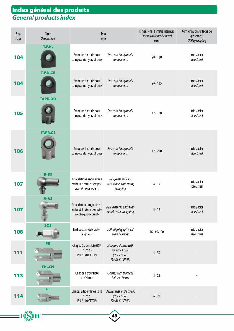
48
Page Page
SigleDesignation
TypeType
Dimensions (diamètre intérieur) Dimensions (inner diameter)
mm.
Combinaison surfaces de glissement
Sliding coupling
Lubrification Lubrication
Température °C Temperature °C
Caractéristiques techniques et principaux domaines d'applicationTechnical details and main application fields
104
T.P.N.
Embouts à rotule pour composants hydrauliques
Rod ends for hydraulic components
20 - 120acier/acier steel/steel
OuiYes
-
Embouts à rotule pour hydraulique, à base rectangulaire, sans axe de centrage; fixation par soudure en acier ST 52-3. Embouts à rotule démontables, conforme DIN 648 série E, fixé à la rotule par des anneaux élastiques. Particulièrement indiqués pour vérins oléodynamiques, réalisés d'après les normes CETOP 1), ils sont dotés de graisseur pour la lubrification.Rod end for hydraulic components with rectangular basis, without dowel pin, it can be connected with steel welding ST 52-3. Detachable spherical rod ends according to DIN 648 series E, joined to the rod end through elastic rings. They are particularly suitable for oleodinamic cylinders, manufactured according CETOP 1) regulations, with grease nipple for lubrication.
104
T.P.N.CE
Embouts à rotule pour composants hydrauliques
Rod ends for hydraulic components
20 - 125acier/acier steel/steel
OuiYes
-
105
TAPR.DO
Embouts à rotule pour composants hydrauliques
Rod ends for hydraulic components
12 - 100acier/acier steel/steel
OuiYes
-
Embout a rotule pour hydraulique, à filetage intérieur conforme DIN 24555. Le corps extérieur est en acier forgé C 45 N et il est doté de graisseur pour la lubrification. Le blocage du filetage se fait à travers des dispositifs présents sur la tige. Rotule conforme DIN 648 série E (ISO 6124/1 série E). Particulièrement indiqués dans le secteur hydraulique pour vérins avec 160 bars de pression, conformes ISO 6020/II.Rod ends for hydraulic components, with internal thread according to DIN 24555. The external housing is made of forged steel C 45 N and has a grease nipple for lubrication. The thread is blocked by devices on the shank. Spherical plain bearing according to DIN 648 series E (ISO 6124/1 series E). They are particularly suitable in the hydraulic field for cylinders with 160 bar pressure according to ISO 6020/II.
106
TAPR.CE
Embouts à rotule pour composants hydrauliques
Rod ends for hydraulic components
12 - 200acier/acier steel/steel
OuiYes
-
Embout a rotule pour hydraulique, à filetage intérieur conforme DIN 24338, plus long par rapport à la série TAPR.N et TAPR.U. Le corps extérieur, doté de graisseur pour la lubrification, est en acier forgé, Jusqu'à la dimension 50 mm, à partir du diamètre 63 mm il est produit en fonte à graphite sphéroïdale. Le blocage du filetage se fait à travers des dispositifs présents sur la tige. Rotule fixée à la tige de l'embout au moyen d'anneaux élastiques. Particulièrement indiqués dans le secteur hydraulique pour vérins avec 160 bars de pression, conforme ISO 6020/II et réalisés d'après les normes CETOP 1) et les normes DIN 2433-24336, ISO 6020/I et 6022.Rod ends for hydraulic components with internal thread according to DIN 24338, longer in comparison to the series TAPR.N and TAPR.U. The external housing, with grease nipple for lubrication, is made of forged steel up to size 50 mm.; starting from diameter 63 mm. it is made of cast iron. The thread is blocked through devices on the shank. Spherical plain bearing connected to the rod end through elastic rings. They are particularly suitable in the hydraulic field for cylinders with 160 bar pressure, according to ISO 6020/II and manufactured as per CETOP 1), DIN 2433-24336 and ISO 6020/I e 6022 regulations.
107
B-BSArticulations angulaires à embout à rotule trempée,
avec étrier à ressort
Ball joints rod ends with shank, with spring
clamping8 - 19
acier/acier steel/steel
OuiYes
-
Les articulations angulaires, tout comme les embouts à rotule auto-aligneurs, sont des dispositifs mécaniques indiqués pour la liaison des parties perpendiculaires. Grâce à leurs caractéristiques de fabrication, elles permettent la transmission de forces alternées et mouvements angulaires et oscillatoires à vitesse réduite, en compensant les flexions angulaires et les déplacements radiaux. La forme A se différencie de la forme B car la première est dotée de bague de sûreté et la deuxième d'un étrier à ressort.Ball joint rod ends, as well as self-aligning rod ends, are mechanical devices suitable to connect perpendicular parts. Their constructive features allow the transmission of alternate forces and angular low speed oscillations, thus compensating angular flexions and radial movements. Type A is different from type B as the first has a safety ring, the second a spring seal.
107
A-AS
Articulations angulaires à embout à rotule trempée,
avec bague de sûreté
Ball joints rod ends with shank, with safety ring
8 - 19acier/acier steel/steel
OuiYes
-
108SQS
Embouts à rotule auto-aligneurs
Self-aligning spherical plain bearings
16 - 80/100acier/acier steel/steel
OuiYes
-
111
FK Chapes à trou fileté (DIN 71752 -
ISO 8140 CETOP)
Standard clevises with threaded hole(DIN 71752 -
ISO 8140 CETOP)
4 - 50 - - -
Les chapes sont des composants mécaniques; particulièrement indiqués dans le secteur pneumatique, hydraulique et mécanique en général. Le montage est normalement effectué avec d'autres pièces, telles que: axes, clips, ressorts, goupilles, rondelles etc... Les chapes peuvent être produites en différents matériaux: acier, acier inoxydable et aluminium et elles ont un filetage dans la partie intérieure de la tige (FK - FK..CN), tandis que dans le modèle FT, le filetage se trouve dans la partie extérieure de la tige.Clevis are mechanical devices particularly suitable in the pneumatic, hydraulic and mechanical field in general. The application usually works together with other products such as pins, clips, springs, split pins, washers an so on. Clevises can be made in different materials: steel, stainless steel and aluminium and have a thread in the internal part of the shank (FK - FK..CN), whereas in the type FT, the thread is located in the external part of the shank.
113
FK..CN
Chapes à trou fileté ex CNomo
Clevises with threaded hole ex CNomo
8 - 25 - - -
114FT Chapes à tige filetée (DIN
71752 - ISO 8140 CETOP)
Clevises with male thread(DIN 71752 -
ISO 8140 CETOP)6 - 20 - - -
Index général des produitsGeneral products index
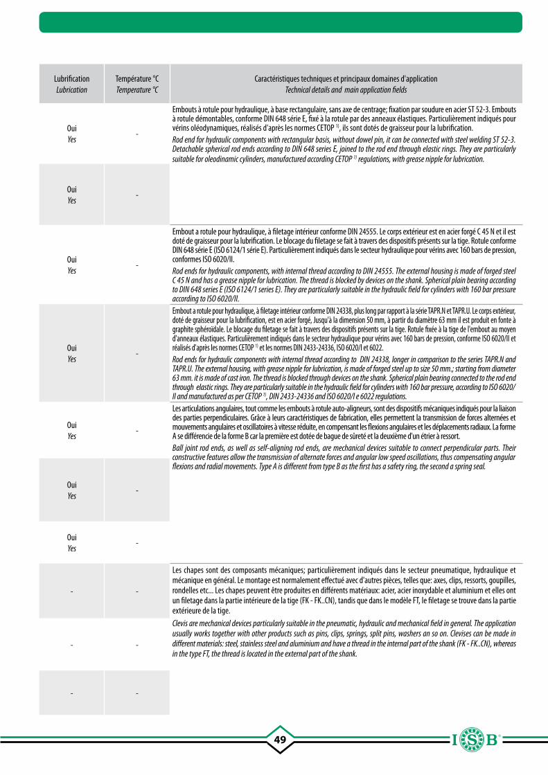
49
Page Page
SigleDesignation
TypeType
Dimensions (diamètre intérieur) Dimensions (inner diameter)
mm.
Combinaison surfaces de glissement
Sliding coupling
Lubrification Lubrication
Température °C Temperature °C
Caractéristiques techniques et principaux domaines d'applicationTechnical details and main application fields
104
T.P.N.
Embouts à rotule pour composants hydrauliques
Rod ends for hydraulic components
20 - 120acier/acier steel/steel
OuiYes
-
Embouts à rotule pour hydraulique, à base rectangulaire, sans axe de centrage; fixation par soudure en acier ST 52-3. Embouts à rotule démontables, conforme DIN 648 série E, fixé à la rotule par des anneaux élastiques. Particulièrement indiqués pour vérins oléodynamiques, réalisés d'après les normes CETOP 1), ils sont dotés de graisseur pour la lubrification.Rod end for hydraulic components with rectangular basis, without dowel pin, it can be connected with steel welding ST 52-3. Detachable spherical rod ends according to DIN 648 series E, joined to the rod end through elastic rings. They are particularly suitable for oleodinamic cylinders, manufactured according CETOP 1) regulations, with grease nipple for lubrication.
104
T.P.N.CE
Embouts à rotule pour composants hydrauliques
Rod ends for hydraulic components
20 - 125acier/acier steel/steel
OuiYes
-
105
TAPR.DO
Embouts à rotule pour composants hydrauliques
Rod ends for hydraulic components
12 - 100acier/acier steel/steel
OuiYes
-
Embout a rotule pour hydraulique, à filetage intérieur conforme DIN 24555. Le corps extérieur est en acier forgé C 45 N et il est doté de graisseur pour la lubrification. Le blocage du filetage se fait à travers des dispositifs présents sur la tige. Rotule conforme DIN 648 série E (ISO 6124/1 série E). Particulièrement indiqués dans le secteur hydraulique pour vérins avec 160 bars de pression, conformes ISO 6020/II.Rod ends for hydraulic components, with internal thread according to DIN 24555. The external housing is made of forged steel C 45 N and has a grease nipple for lubrication. The thread is blocked by devices on the shank. Spherical plain bearing according to DIN 648 series E (ISO 6124/1 series E). They are particularly suitable in the hydraulic field for cylinders with 160 bar pressure according to ISO 6020/II.
106
TAPR.CE
Embouts à rotule pour composants hydrauliques
Rod ends for hydraulic components
12 - 200acier/acier steel/steel
OuiYes
-
Embout a rotule pour hydraulique, à filetage intérieur conforme DIN 24338, plus long par rapport à la série TAPR.N et TAPR.U. Le corps extérieur, doté de graisseur pour la lubrification, est en acier forgé, Jusqu'à la dimension 50 mm, à partir du diamètre 63 mm il est produit en fonte à graphite sphéroïdale. Le blocage du filetage se fait à travers des dispositifs présents sur la tige. Rotule fixée à la tige de l'embout au moyen d'anneaux élastiques. Particulièrement indiqués dans le secteur hydraulique pour vérins avec 160 bars de pression, conforme ISO 6020/II et réalisés d'après les normes CETOP 1) et les normes DIN 2433-24336, ISO 6020/I et 6022.Rod ends for hydraulic components with internal thread according to DIN 24338, longer in comparison to the series TAPR.N and TAPR.U. The external housing, with grease nipple for lubrication, is made of forged steel up to size 50 mm.; starting from diameter 63 mm. it is made of cast iron. The thread is blocked through devices on the shank. Spherical plain bearing connected to the rod end through elastic rings. They are particularly suitable in the hydraulic field for cylinders with 160 bar pressure, according to ISO 6020/II and manufactured as per CETOP 1), DIN 2433-24336 and ISO 6020/I e 6022 regulations.
107
B-BSArticulations angulaires à embout à rotule trempée,
avec étrier à ressort
Ball joints rod ends with shank, with spring
clamping8 - 19
acier/acier steel/steel
OuiYes
-
Les articulations angulaires, tout comme les embouts à rotule auto-aligneurs, sont des dispositifs mécaniques indiqués pour la liaison des parties perpendiculaires. Grâce à leurs caractéristiques de fabrication, elles permettent la transmission de forces alternées et mouvements angulaires et oscillatoires à vitesse réduite, en compensant les flexions angulaires et les déplacements radiaux. La forme A se différencie de la forme B car la première est dotée de bague de sûreté et la deuxième d'un étrier à ressort.Ball joint rod ends, as well as self-aligning rod ends, are mechanical devices suitable to connect perpendicular parts. Their constructive features allow the transmission of alternate forces and angular low speed oscillations, thus compensating angular flexions and radial movements. Type A is different from type B as the first has a safety ring, the second a spring seal.
107
A-AS
Articulations angulaires à embout à rotule trempée,
avec bague de sûreté
Ball joints rod ends with shank, with safety ring
8 - 19acier/acier steel/steel
OuiYes
-
108SQS
Embouts à rotule auto-aligneurs
Self-aligning spherical plain bearings
16 - 80/100acier/acier steel/steel
OuiYes
-
111
FK Chapes à trou fileté (DIN 71752 -
ISO 8140 CETOP)
Standard clevises with threaded hole(DIN 71752 -
ISO 8140 CETOP)
4 - 50 - - -
Les chapes sont des composants mécaniques; particulièrement indiqués dans le secteur pneumatique, hydraulique et mécanique en général. Le montage est normalement effectué avec d'autres pièces, telles que: axes, clips, ressorts, goupilles, rondelles etc... Les chapes peuvent être produites en différents matériaux: acier, acier inoxydable et aluminium et elles ont un filetage dans la partie intérieure de la tige (FK - FK..CN), tandis que dans le modèle FT, le filetage se trouve dans la partie extérieure de la tige.Clevis are mechanical devices particularly suitable in the pneumatic, hydraulic and mechanical field in general. The application usually works together with other products such as pins, clips, springs, split pins, washers an so on. Clevises can be made in different materials: steel, stainless steel and aluminium and have a thread in the internal part of the shank (FK - FK..CN), whereas in the type FT, the thread is located in the external part of the shank.
113
FK..CN
Chapes à trou fileté ex CNomo
Clevises with threaded hole ex CNomo
8 - 25 - - -
114FT Chapes à tige filetée (DIN
71752 - ISO 8140 CETOP)
Clevises with male thread(DIN 71752 -
ISO 8140 CETOP)6 - 20 - - -
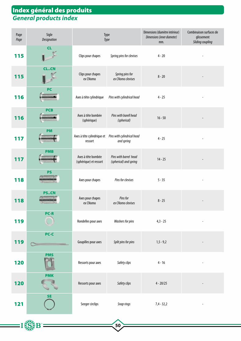
50
Index général des produitsGeneral products index
Page Page
SigleDesignation
TypeType
Dimensions (diamètre intérieur) Dimensions (inner diameter)
mm.
Combinaison surfaces de glissement
Sliding coupling
Lubrification Lubrication
Température °C Temperature °C
Caractéristiques techniques et principaux domaines d'applicationTechnical details and main application fields
115
CL
Clips pour chapes Spring pins for clevises 4 - 20 - - -
Tous les produits (clips, axes, rondelle, goupilles, ressorts, anneau seeger) doivent être utilisés principalement avec les chapes. Les principales caractéristiques sont reportées dans les tableaux des dimensions correspondants, avec aussi les cotes et les tolérances des produits.
All items (clips, pins, washers, split pins, springs, seeger) are to be used mainly together with clevises. The main characteristics are suitable in the relevant dimension tables, together with dimensions and tolerances of the different products.
115
CL..CNClips pour chapes
ex CNomoSpring pins for
ex CNomo clevises8 - 20 - - -
116
PC
Axes à tête cylindrique Pins with cylindrical head 4 - 25 - - -
116
PCBAxes à tête bombée
(sphérique)Pins with barell head
(spherical)16 - 50 - - -
117
PMAxes à tête cylindrique et
ressortPins with cylindrical head
and spring4 - 25 - - -
117
PMBAxes à tête bombée
(sphérique) et ressortPins with barrel head (spherical) and spring
14 - 25 - - -
118
PS
Axes pour chapes Pins for clevises 5 - 35 - - -
118
PS..CNAxes pour chapes
ex CNomo Pins for
ex CNomo clevises8 - 25 - - -
119
PC-R
Rondelles pour axes Washers for pins 4,3 - 25 - - -
119
PC-C
Goupilles pour axes Split pins for pins 1,5 - 9,2 - - -
120
PMS
Ressorts pour axes Safety clips 4 - 16 - - -
120
PMK
Ressorts pour axes Safety clips 4 - 20/25 - - -
121
SE
Seeger circlips Snap rings 7,4 - 32,2 - - -
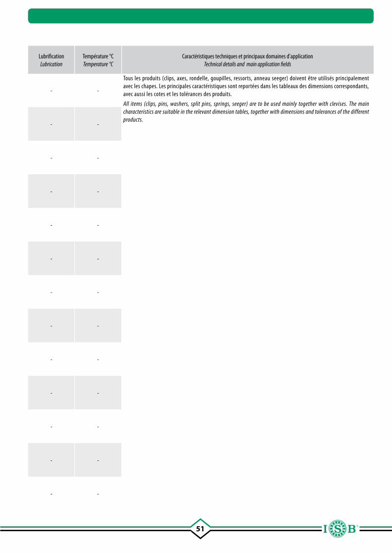
51
Page Page
SigleDesignation
TypeType
Dimensions (diamètre intérieur) Dimensions (inner diameter)
mm.
Combinaison surfaces de glissement
Sliding coupling
Lubrification Lubrication
Température °C Temperature °C
Caractéristiques techniques et principaux domaines d'applicationTechnical details and main application fields
115
CL
Clips pour chapes Spring pins for clevises 4 - 20 - - -
Tous les produits (clips, axes, rondelle, goupilles, ressorts, anneau seeger) doivent être utilisés principalement avec les chapes. Les principales caractéristiques sont reportées dans les tableaux des dimensions correspondants, avec aussi les cotes et les tolérances des produits.
All items (clips, pins, washers, split pins, springs, seeger) are to be used mainly together with clevises. The main characteristics are suitable in the relevant dimension tables, together with dimensions and tolerances of the different products.
115
CL..CNClips pour chapes
ex CNomoSpring pins for
ex CNomo clevises8 - 20 - - -
116
PC
Axes à tête cylindrique Pins with cylindrical head 4 - 25 - - -
116
PCBAxes à tête bombée
(sphérique)Pins with barell head
(spherical)16 - 50 - - -
117
PMAxes à tête cylindrique et
ressortPins with cylindrical head
and spring4 - 25 - - -
117
PMBAxes à tête bombée
(sphérique) et ressortPins with barrel head (spherical) and spring
14 - 25 - - -
118
PS
Axes pour chapes Pins for clevises 5 - 35 - - -
118
PS..CNAxes pour chapes
ex CNomo Pins for
ex CNomo clevises8 - 25 - - -
119
PC-R
Rondelles pour axes Washers for pins 4,3 - 25 - - -
119
PC-C
Goupilles pour axes Split pins for pins 1,5 - 9,2 - - -
120
PMS
Ressorts pour axes Safety clips 4 - 16 - - -
120
PMK
Ressorts pour axes Safety clips 4 - 20/25 - - -
121
SE
Seeger circlips Snap rings 7,4 - 32,2 - - -
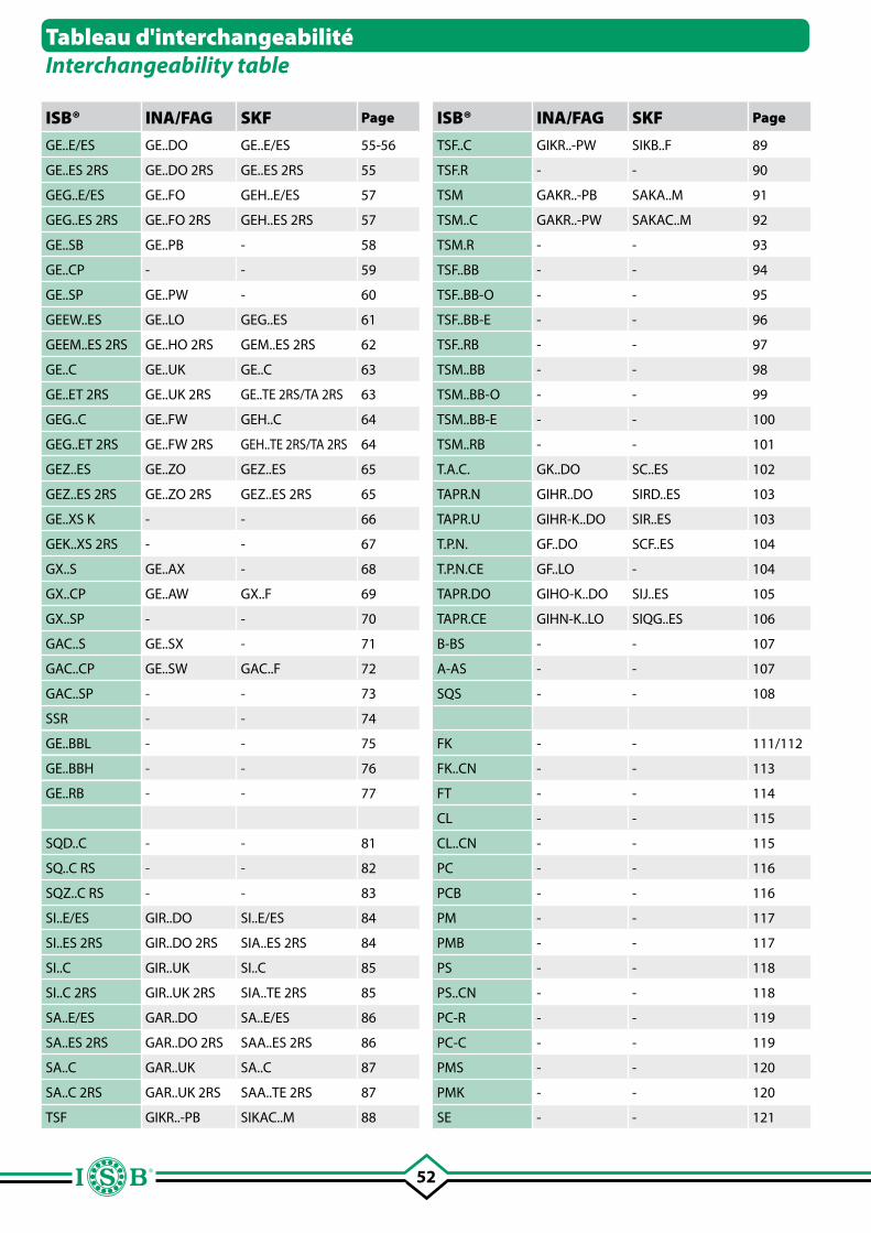
52
Tableau d'interchangeabilitéInterchangeability table
ISB® INA/FAG SKF Page
GE..E/ES GE..DO GE..E/ES 55-56
GE..ES 2RS GE..DO 2RS GE..ES 2RS 55
GEG..E/ES GE..FO GEH..E/ES 57
GEG..ES 2RS GE..FO 2RS GEH..ES 2RS 57
GE..SB GE..PB - 58
GE..CP - - 59
GE..SP GE..PW - 60
GEEW..ES GE..LO GEG..ES 61
GEEM..ES 2RS GE..HO 2RS GEM..ES 2RS 62
GE..C GE..UK GE..C 63
GE..ET 2RS GE..UK 2RS GE..TE 2RS/TA 2RS 63
GEG..C GE..FW GEH..C 64
GEG..ET 2RS GE..FW 2RS GEH..TE 2RS/TA 2RS 64
GEZ..ES GE..ZO GEZ..ES 65
GEZ..ES 2RS GE..ZO 2RS GEZ..ES 2RS 65
GE..XS K - - 66
GEK..XS 2RS - - 67
GX..S GE..AX - 68
GX..CP GE..AW GX..F 69
GX..SP - - 70
GAC..S GE..SX - 71
GAC..CP GE..SW GAC..F 72
GAC..SP - - 73
SSR - - 74
GE..BBL - - 75
GE..BBH - - 76
GE..RB - - 77
SQD..C - - 81
SQ..C RS - - 82
SQZ..C RS - - 83
SI..E/ES GIR..DO SI..E/ES 84
SI..ES 2RS GIR..DO 2RS SIA..ES 2RS 84
SI..C GIR..UK SI..C 85
SI..C 2RS GIR..UK 2RS SIA..TE 2RS 85
SA..E/ES GAR..DO SA..E/ES 86
SA..ES 2RS GAR..DO 2RS SAA..ES 2RS 86
SA..C GAR..UK SA..C 87
SA..C 2RS GAR..UK 2RS SAA..TE 2RS 87
TSF GIKR..-PB SIKAC..M 88
ISB® INA/FAG SKF Page
TSF..C GIKR..-PW SIKB..F 89
TSF.R - - 90
TSM GAKR..-PB SAKA..M 91
TSM..C GAKR..-PW SAKAC..M 92
TSM.R - - 93
TSF..BB - - 94
TSF..BB-O - - 95
TSF..BB-E - - 96
TSF..RB - - 97
TSM..BB - - 98
TSM..BB-O - - 99
TSM..BB-E - - 100
TSM..RB - - 101
T.A.C. GK..DO SC..ES 102
TAPR.N GIHR..DO SIRD..ES 103
TAPR.U GIHR-K..DO SIR..ES 103
T.P.N. GF..DO SCF..ES 104
T.P.N.CE GF..LO - 104
TAPR.DO GIHO-K..DO SIJ..ES 105
TAPR.CE GIHN-K..LO SIQG..ES 106
B-BS - - 107
A-AS - - 107
SQS - - 108
FK - - 111/112
FK..CN - - 113
FT - - 114
CL - - 115
CL..CN - - 115
PC - - 116
PCB - - 116
PM - - 117
PMB - - 117
PS - - 118
PS..CN - - 118
PC-R - - 119
PC-C - - 119
PMS - - 120
PMK - - 120
SE - - 121
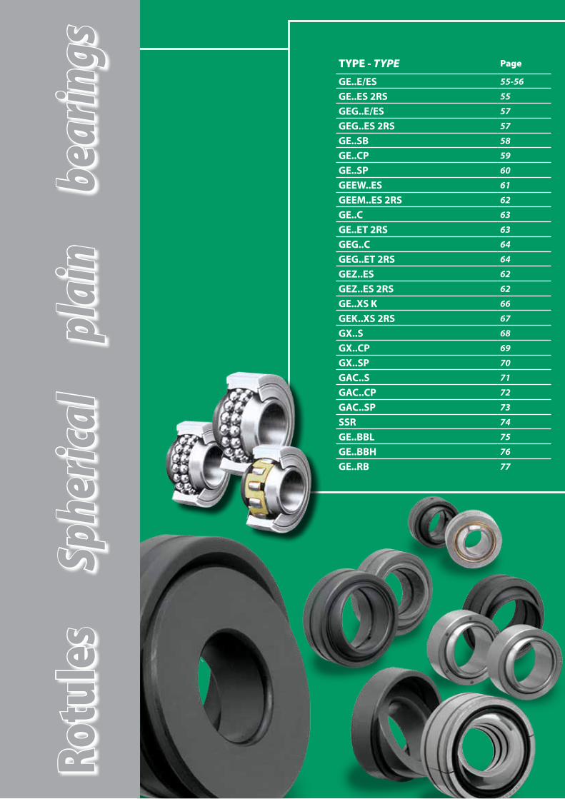
Rotu
les
Sphe
rical
pl
ain
bear
ings TYPE - TYPE Page
GE..E/ES 55-56
GE..ES 2RS 55
GEG..E/ES 57
GEG..ES 2RS 57
GE..SB 58
GE..CP 59
GE..SP 60
GEEW..ES 61
GEEM..ES 2RS 62
GE..C 63
GE..ET 2RS 63
GEG..C 64
GEG..ET 2RS 64
GEZ..ES 62
GEZ..ES 2RS 62
GE..XS K 66
GEK..XS 2RS 67
GX..S 68
GX..CP 69
GX..SP 70
GAC..S 71
GAC..CP 72
GAC..SP 73
SSR 74
GE..BBL 75
GE..BBH 76
GE..RB 77

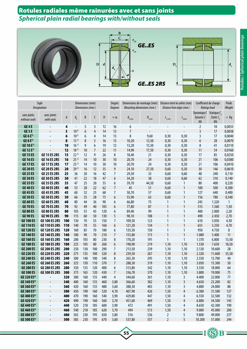
55
BC r2S
r1S
D d
αdk
Da da
Rotules radiales même rainurées avec et sans jointsSpherical plain radial bearings with/without seals
GE..ES
GE..ES 2RS
SigleDesignation
Dimensions (mm)Dimensions (mm.)
DegrésDegrees
Dimensions de montage (mm)Mounting dimensions (mm.)
Distance entre les arêtes (mm)Distance from edges (mm.)
Coefficient de chargeRatings load
PoidsWeight
sans joints without seals
avec jointswith seals
d dk
B C D ≈ α da max
Da min
r1s min
r2smin
Dynamique CDynamic C
KN
Statique Co
Static Co
KN≈ Kg
GE 4 E - 4 - 5 3 12 16 6 - - - 2 10 0,0033GE 5 E - 5 10 2) 6 4 14 13 7 - - - 3 17 0,0038
GE 6 E1) - 6 10 2) 6 4 14 13 8 9,60 0,30 0,30 3 17 0,0040GE 8 E1) - 8 13 2) 8 5 16 15 10,20 12,50 0,30 0,30 6 28 0,0070
GE 10 E1) - 10 16 2) 9 6 19 12 13,20 15,50 0,30 0,30 8 41 0,0110GE 12 E1) - 12 18 2) 10 7 22 11 14,90 17,50 0,30 0,30 11 54 0,0160GE 15 ES GE 15 ES 2RS 15 22 2) 12 9 26 8 18,40 21 0,30 0,30 17 85 0,0250GE 16 ES GE 16 ES 2RS 16 25 2) 14 10 30 10 20,70 24 0,30 0,30 21 106 0,0380GE 17 ES GE 17 ES 2RS 17 25 2) 14 10 30 10 20,70 24 0,30 0,30 21 106 0,0410GE 20 ES GE 20 ES 2RS 20 29 2) 16 12 35 9 24,10 27,50 0,60 0,30 30 146 0,0610GE 25 ES GE 25 ES 2RS 25 36 20 16 42 7 29,30 33 0,60 0,60 48 240 0,110GE 30 ES GE 30 ES 2RS 30 41 22 18 47 6 34,20 38 0,60 0,60 62 310 0,140GE 35 ES GE 35 ES 2RS 35 47 25 20 55 6 39,70 44,50 0,60 1 80 400 0,220GE 40 ES GE 40 ES 2RS 40 53 28 22 62 7 45 51 0,60 1 100 500 0,300GE 45 ES GE 45 ES 2RS 45 60 32 25 68 7 50,70 57 0,60 1 127 640 0,400GE 50 ES GE 50 ES 2RS 50 66 35 28 75 6 55,90 63 0,60 1 156 780 0,540GE 60 ES GE 60 ES 2RS 60 80 44 36 90 6 66,80 75 1 1 245 1.220 1GE 70 ES GE 70 ES 2RS 70 92 49 40 105 6 77,80 87 1 1 315 1.560 1,50GE 80 ES GE 80 ES 2RS 80 105 55 45 120 6 89,40 99 1 1 400 2.000 2,20GE 90 ES GE 90 ES 2RS 90 115 60 50 130 5 98,10 108 1 1 490 2.450 2,70
GE 100 ES GE 100 ES 2RS 100 130 70 55 150 7 109,50 123 1 1 610 3.050 4,30GE 110 ES GE 110 ES 2RS 110 140 70 55 160 6 121,20 134 1 1 655 3.250 4,70GE 120 ES GE 120 ES 2RS 120 160 85 70 180 6 135,50 150 1 1 950 4.750 8GE 140 ES GE 140 ES 2RS 140 180 90 70 210 7 155,80 173 1 1 1.080 5.400 11GE 160 ES GE 160 ES 2RS 160 200 105 80 230 8 170,20 191 1 1 1.370 6.800 13,50GE 180 ES GE 180 ES 2RS 180 225 105 80 260 6 198,90 219 1,10 1,10 1.530 7.650 18,50GE 200 ES GE 200 ES 2RS 200 250 130 100 290 7 213,50 239 1,10 1,10 2.120 10.600 28GE 220 ES GE 220 ES 2RS 220 275 135 100 320 8 239,50 267 1,10 1,10 2.320 11.600 35,50GE 240 ES GE 240 ES 2RS 240 300 140 100 340 8 265,30 295 1,10 1,10 2.550 12.700 40GE 260 ES GE 260 ES 2RS 260 325 150 110 370 7 288,30 319 1,10 1,10 3.050 15.300 50GE 280 ES GE 280 ES 2RS 280 350 155 120 400 6 313,80 342 1,10 1,10 3.550 18.000 64GE 300 ES GE 300 ES 2RS 300 375 165 120 430 7 336,70 370 1,10 1,10 3.800 19.000 75
GE 320 ES* - 320 380 160 135 440 4 344,60 361 1,10 3 4.400 22.000 77GE 340 ES* - 340 400 160 135 460 3,80 366,60 382 1,10 3 4.650 23.200 82GE 360 ES* - 360 420 160 135 480 3,60 388,30 403 1,10 3 4.800 24.000 88GE 380 ES* - 380 450 190 160 520 4,10 407,90 426 1,50 4 6.300 31.500 127GE 400 ES* - 400 470 190 160 540 3,90 429,80 447 1,50 4 6.550 32.500 132GE 420 ES* - 420 490 190 160 560 3,70 451,60 469 1,50 4 6.800 34.500 145GE 440 ES* - 440 520 218 185 600 3,90 472 491 1,50 4 8.650 42.300 190GE 460 ES* - 460 540 218 185 620 3,70 494 513 1,50 4 9.000 45.000 200GE 480 ES* - 480 565 230 195 650 3,80 516 536 2 5 9.800 49.000 237GE 500 ES* - 500 585 230 195 670 3,60 537,80 557 2 5 10.200 51.000 244
Rotu
les
/ Sph
eric
al p
lain
bea
ring
s
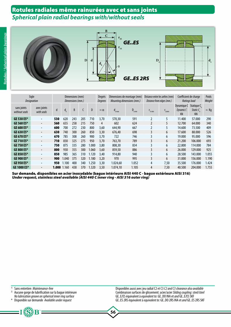
56
Rotules radiales même rainurées avec et sans jointsSpherical plain radial bearings with/without seals
SigleDesignation
Dimensions (mm)Dimensions (mm.)
DegrésDegrees
Dimensions de montage (mm)Mounting dimensions (mm.)
Distance entre les arêtes (mm)Distance from edges (mm.)
Coefficient de chargeRatings load
PoidsWeight
sans joints without seals
avec jointswith seals
d dk
B C D ≈ α da max
Da min
r1s min
r2smin
Dynamique CDynamic C
KN
Statique Co
Static Co
KN≈ Kg
GE 530 ES* - 530 620 243 205 710 3,70 570,30 591 2 5 11.400 57.000 290GE 560 ES* - 560 655 258 215 750 4 602 624 2 5 12.700 64.000 340GE 600 ES* - 600 700 272 230 800 3,60 644,90 667 2 5 14.600 73.500 409GE 630 ES* - 630 740 300 260 850 3,30 676,40 698 3 6 17.600 88.000 526GE 670 ES* - 670 785 308 260 900 3,70 722 746 3 6 19.000 95.000 596GE 710 ES* - 710 830 325 275 950 3,70 763,70 789 3 6 21.200 106.000 693GE 750 ES* - 750 875 335 280 1.000 3,80 808,30 834 3 6 22.800 114.000 784GE 800 ES* - 800 930 355 300 1.060 3,60 859,50 886 3 6 26.000 129.000 925GE 850 ES* - 850 985 365 310 1.120 3,40 914,80 940 3 6 28.500 143.000 1.055GE 900 ES* - 900 1.040 375 320 1.180 3,20 970 995 3 6 31.000 156.000 1.190GE 950 ES* - 950 1.100 400 340 1.250 3,30 1.024,60 1.052 4 7,50 35.500 176.000 1.424
GE 1000 ES* - 1.000 1.160 438 370 1.320 3,50 1.074,10 1.105 4 7,50 40.500 204.000 1.755
1) Sans entretien Maintenance-free2) Aucune gorge de lubrification sur la bague intérieure No lubrication groove on spherical inner ring surface* Disponible sur demande Available under request
Disponibles aussi avec jeu radial C2 et C3 C2 and C3 clearance also available Combinaison surfaces de glissement: acier/acier Sliding coupling: steel/steelGE..E/ES équivalent à equivalent to: GE..DO INA et and GE..E/ES SKFGE..ES 2RS équivalent à equivalent to: GE..DO 2RS INA et and GE..ES 2RS SKF
Sur demande, disponibles en acier inoxydable (bague intérieure AISI 440 C - bague extérieure AISI 316)Under request, stainless steel available (AISI 440 C inner ring - AISI 316 outer ring)
BC r2S
r1S
D d
αdk
Da da
GE..ES
GE..ES 2RS
Rotu
les
/ Sph
eric
al p
lain
bea
ring
s
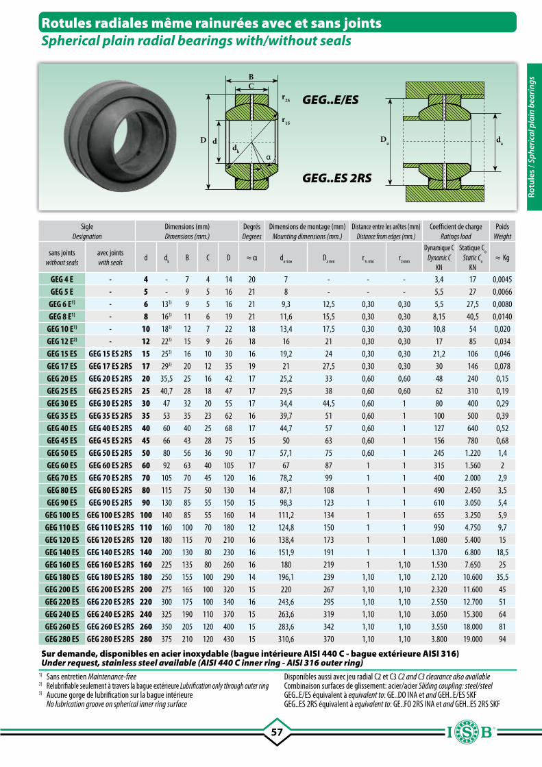
57
Sur demande, disponibles en acier inoxydable (bague intérieure AISI 440 C - bague extérieure AISI 316)Under request, stainless steel available (AISI 440 C inner ring - AISI 316 outer ring)
BC
r2S
r1S
D d
αdk
daDa
SigleDesignation
Dimensions (mm)Dimensions (mm.)
DegrésDegrees
Dimensions de montage (mm)Mounting dimensions (mm.)
Distance entre les arêtes (mm)Distance from edges (mm.)
Coefficient de chargeRatings load
PoidsWeight
sans jointswithout seals
avec jointswith seals
d dk
B C D ≈ α da max
Da min
r1s min
r2smin
Dynamique CDynamic C
KN
Statique Co
Static Co
KN≈ Kg
GEG 4 E - 4 - 7 4 14 20 7 - - - 3,4 17 0,0045GEG 5 E - 5 - 9 5 16 21 8 - - - 5,5 27 0,0066
GEG 6 E1) - 6 133) 9 5 16 21 9,3 12,5 0,30 0,30 5,5 27,5 0,0080GEG 8 E1) - 8 163) 11 6 19 21 11,6 15,5 0,30 0,30 8,15 40,5 0,0140
GEG 10 E1) - 10 183) 12 7 22 18 13,4 17,5 0,30 0,30 10,8 54 0,020GEG 12 E2) - 12 223) 15 9 26 18 16 21 0,30 0,30 17 85 0,034GEG 15 ES GEG 15 ES 2RS 15 253) 16 10 30 16 19,2 24 0,30 0,30 21,2 106 0,046GEG 17 ES GEG 17 ES 2RS 17 293) 20 12 35 19 21 27,5 0,30 0,30 30 146 0,078GEG 20 ES GEG 20 ES 2RS 20 35,5 25 16 42 17 25,2 33 0,60 0,60 48 240 0,15GEG 25 ES GEG 25 ES 2RS 25 40,7 28 18 47 17 29,5 38 0,60 0,60 62 310 0,19GEG 30 ES GEG 30 ES 2RS 30 47 32 20 55 17 34,4 44,5 0,60 1 80 400 0,29GEG 35 ES GEG 35 ES 2RS 35 53 35 23 62 16 39,7 51 0,60 1 100 500 0,39GEG 40 ES GEG 40 ES 2RS 40 60 40 25 68 17 44,7 57 0,60 1 127 640 0,52GEG 45 ES GEG 45 ES 2RS 45 66 43 28 75 15 50 63 0,60 1 156 780 0,68GEG 50 ES GEG 50 ES 2RS 50 80 56 36 90 17 57,1 75 0,60 1 245 1.220 1,4GEG 60 ES GEG 60 ES 2RS 60 92 63 40 105 17 67 87 1 1 315 1.560 2GEG 70 ES GEG 70 ES 2RS 70 105 70 45 120 16 78,2 99 1 1 400 2.000 2,9GEG 80 ES GEG 80 ES 2RS 80 115 75 50 130 14 87,1 108 1 1 490 2.450 3,5GEG 90 ES GEG 90 ES 2RS 90 130 85 55 150 15 98,3 123 1 1 610 3.050 5,4
GEG 100 ES GEG 100 ES 2RS 100 140 85 55 160 14 111,2 134 1 1 655 3.250 5,9GEG 110 ES GEG 110 ES 2RS 110 160 100 70 180 12 124,8 150 1 1 950 4.750 9,7GEG 120 ES GEG 120 ES 2RS 120 180 115 70 210 16 138,4 173 1 1 1.080 5.400 15GEG 140 ES GEG 140 ES 2RS 140 200 130 80 230 16 151,9 191 1 1 1.370 6.800 18,5GEG 160 ES GEG 160 ES 2RS 160 225 135 80 260 16 180 219 1 1,10 1.530 7.650 25GEG 180 ES GEG 180 ES 2RS 180 250 155 100 290 14 196,1 239 1,10 1,10 2.120 10.600 35,5GEG 200 ES GEG 200 ES 2RS 200 275 165 100 320 15 220 267 1,10 1,10 2.320 11.600 45GEG 220 ES GEG 220 ES 2RS 220 300 175 100 340 16 243,6 295 1,10 1,10 2.550 12.700 51GEG 240 ES GEG 240 ES 2RS 240 325 190 110 370 15 263,6 319 1,10 1,10 3.050 15.300 64GEG 260 ES GEG 260 ES 2RS 260 350 205 120 400 15 283,6 342 1,10 1,10 3.550 18.000 81GEG 280 ES GEG 280 ES 2RS 280 375 210 120 430 15 310,6 370 1,10 1,10 3.800 19.000 94
Rotules radiales même rainurées avec et sans jointsSpherical plain radial bearings with/without seals
GEG..E/ES
GEG..ES 2RS
1) Sans entretien Maintenance-free2) Relubrifiable seulement à travers la bague extérieure Lubrification only through outer ring3) Aucune gorge de lubrification sur la bague intérieure No lubrication groove on spherical inner ring surface
Disponibles aussi avec jeu radial C2 et C3 C2 and C3 clearance also availableCombinaison surfaces de glissement: acier/acier Sliding coupling: steel/steelGEG..E/ES équivalent à equivalent to: GE..DO INA et and GEH..E/ES SKFGEG..ES 2RS équivalent à equivalent to: GE..FO 2RS INA et and GEH..ES 2RS SKF
Rotu
les
/ Sph
eric
al p
lain
bea
ring
s
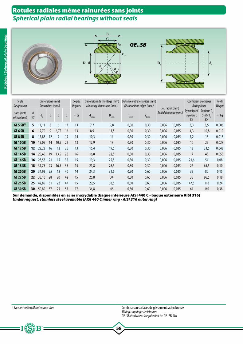
58
BC
r2S
r1S
D d
αdk
daDa
SigleDesignation
Dimensions (mm)Dimensions (mm.)
DegrésDegrees
Dimensions de montage (mm)Mounting dimensions (mm.)
Distance entre les arêtes (mm)Distance from edges (mm.)
Jeu radial (mm)Radial clearance (mm.)
Coefficient de chargeRatings load
PoidsWeight
sans jointswithout seals
dH7
dk
B C D ≈ α da max
Da min
r1s min
r2smin
Dynamique CDynamic C
KN
Statique Co
Static Co
KN≈ Kg
GE 5 SB1) 5 11,11 8 6 13 13 7,7 9,8 0,30 0,30 0,006 0,035 3,3 8,5 0,006
GE 6 SB 6 12,70 9 6,75 16 13 8,9 11,5 0,30 0,30 0,006 0,035 4,3 10,8 0,010
GE 8 SB 8 15,88 12 9 19 14 10,3 14 0,30 0,30 0,006 0,035 7,2 18 0,018
GE 10 SB 10 19,05 14 10,5 22 13 12,9 17 0,30 0,30 0,006 0,035 10 25 0,027
GE 12 SB 12 22,23 16 12 26 13 15,4 19,5 0,30 0,30 0,006 0,035 13 33,5 0,043
GE 14 SB 14 25,40 19 13,5 28 16 16,8 22,5 0,30 0,30 0,006 0,035 17 43 0,055
GE 16 SB 16 28,58 21 15 32 15 19,3 25,5 0,30 0,30 0,006 0,035 21,6 54 0,08
GE 18 SB 18 31,75 23 16,5 35 15 21,8 28,5 0,30 0,30 0,006 0,035 26 65,5 0,10
GE 20 SB 20 34,93 25 18 40 14 24,3 31,5 0,30 0,60 0,006 0,035 32 80 0,15
GE 22 SB 22 38,10 28 20 42 15 25,8 34 0,30 0,60 0,006 0,035 38 96,5 0,18
GE 25 SB 25 42,85 31 22 47 15 29,5 38,5 0,30 0,60 0,006 0,035 47,5 118 0,24
GE 30 SB 30 50,80 37 25 55 17 34,8 46 0,30 0,60 0,006 0,035 64 160 0,38
Rotules radiales même rainurées sans jointsSpherical plain radial bearings without seals
GE..SB
1) Sans entretien Maintenance-free Combinaison surfaces de glissement: acier/bronze Sliding coupling: steel/bronzeGE..SB équivalent à equivalent to: GE..PB INA
Sur demande, disponibles en acier inoxydable (bague intérieure AISI 440 C - bague extérieure AISI 316)Under request, stainless steel available (AISI 440 C inner ring - AISI 316 outer ring)
Rotu
les
/ Sph
eric
al p
lain
bea
ring
s
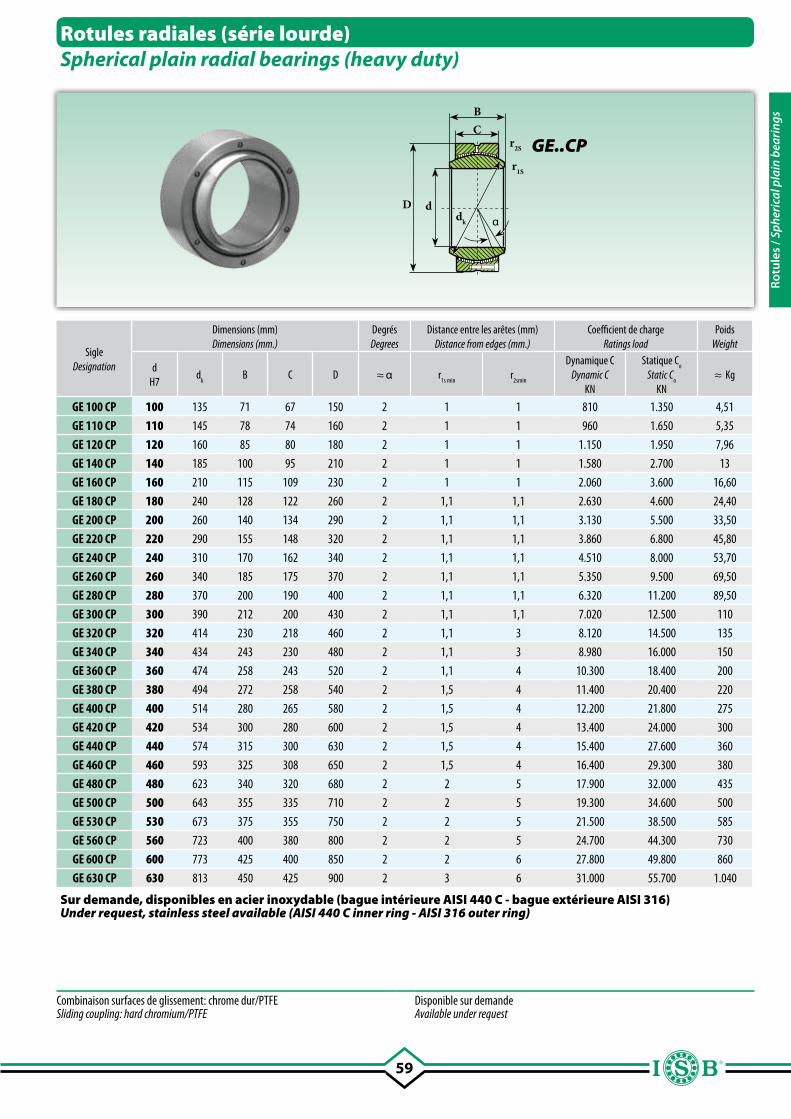
59
BC
r2S
r1S
Dαdk
d
SigleDesignation
Dimensions (mm)Dimensions (mm.)
DegrésDegrees
Distance entre les arêtes (mm)Distance from edges (mm.)
Coefficient de chargeRatings load
PoidsWeight
dH7
dk
B C D ≈ α r1s min
r2smin
Dynamique CDynamic C
KN
Statique Co
Static Co
KN≈ Kg
GE 100 CP 100 135 71 67 150 2 1 1 810 1.350 4,51
GE 110 CP 110 145 78 74 160 2 1 1 960 1.650 5,35
GE 120 CP 120 160 85 80 180 2 1 1 1.150 1.950 7,96
GE 140 CP 140 185 100 95 210 2 1 1 1.580 2.700 13
GE 160 CP 160 210 115 109 230 2 1 1 2.060 3.600 16,60
GE 180 CP 180 240 128 122 260 2 1,1 1,1 2.630 4.600 24,40
GE 200 CP 200 260 140 134 290 2 1,1 1,1 3.130 5.500 33,50
GE 220 CP 220 290 155 148 320 2 1,1 1,1 3.860 6.800 45,80
GE 240 CP 240 310 170 162 340 2 1,1 1,1 4.510 8.000 53,70
GE 260 CP 260 340 185 175 370 2 1,1 1,1 5.350 9.500 69,50
GE 280 CP 280 370 200 190 400 2 1,1 1,1 6.320 11.200 89,50
GE 300 CP 300 390 212 200 430 2 1,1 1,1 7.020 12.500 110
GE 320 CP 320 414 230 218 460 2 1,1 3 8.120 14.500 135
GE 340 CP 340 434 243 230 480 2 1,1 3 8.980 16.000 150
GE 360 CP 360 474 258 243 520 2 1,1 4 10.300 18.400 200
GE 380 CP 380 494 272 258 540 2 1,5 4 11.400 20.400 220
GE 400 CP 400 514 280 265 580 2 1,5 4 12.200 21.800 275
GE 420 CP 420 534 300 280 600 2 1,5 4 13.400 24.000 300
GE 440 CP 440 574 315 300 630 2 1,5 4 15.400 27.600 360
GE 460 CP 460 593 325 308 650 2 1,5 4 16.400 29.300 380
GE 480 CP 480 623 340 320 680 2 2 5 17.900 32.000 435
GE 500 CP 500 643 355 335 710 2 2 5 19.300 34.600 500
GE 530 CP 530 673 375 355 750 2 2 5 21.500 38.500 585
GE 560 CP 560 723 400 380 800 2 2 5 24.700 44.300 730
GE 600 CP 600 773 425 400 850 2 2 6 27.800 49.800 860
GE 630 CP 630 813 450 425 900 2 3 6 31.000 55.700 1.040
Rotules radiales (série lourde)Spherical plain radial bearings (heavy duty)
Combinaison surfaces de glissement: chrome dur/PTFE Sliding coupling: hard chromium/PTFE
Disponible sur demande Available under request
GE..CP
Sur demande, disponibles en acier inoxydable (bague intérieure AISI 440 C - bague extérieure AISI 316)Under request, stainless steel available (AISI 440 C inner ring - AISI 316 outer ring)
Rotu
les
/ Sph
eric
al p
lain
bea
ring
s
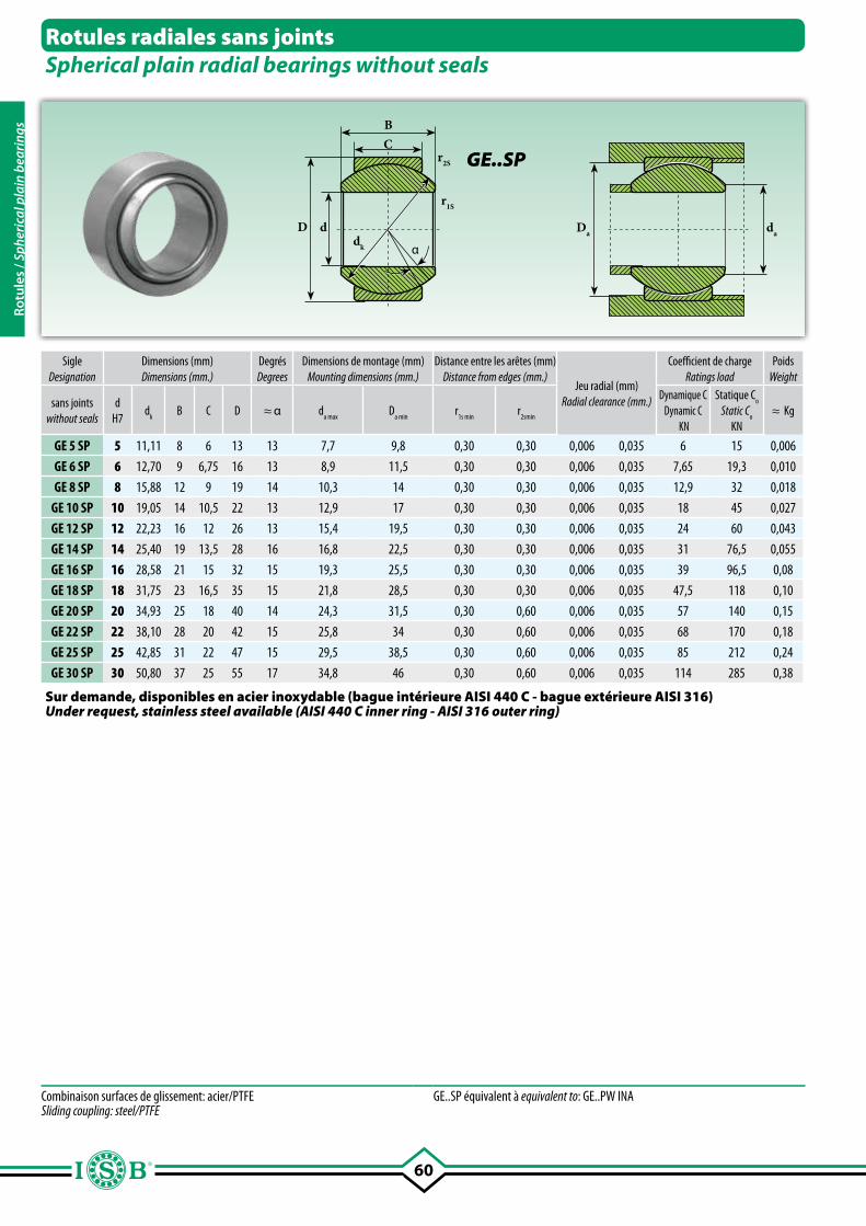
60
BC
D ddk
r1S
α
r2S
daDa
Sur demande, disponibles en acier inoxydable (bague intérieure AISI 440 C - bague extérieure AISI 316)Under request, stainless steel available (AISI 440 C inner ring - AISI 316 outer ring)
SigleDesignation
Dimensions (mm)Dimensions (mm.)
DegrésDegrees
Dimensions de montage (mm)Mounting dimensions (mm.)
Distance entre les arêtes (mm)Distance from edges (mm.)
Jeu radial (mm)Radial clearance (mm.)
Coefficient de chargeRatings load
PoidsWeight
sans jointswithout seals
dH7
dk
B C D ≈ α da max
Da min
r1s min
r2smin
Dynamique C Dynamic C
KN
Statique Co
Static Co
KN≈ Kg
GE 5 SP 5 11,11 8 6 13 13 7,7 9,8 0,30 0,30 0,006 0,035 6 15 0,006
GE 6 SP 6 12,70 9 6,75 16 13 8,9 11,5 0,30 0,30 0,006 0,035 7,65 19,3 0,010
GE 8 SP 8 15,88 12 9 19 14 10,3 14 0,30 0,30 0,006 0,035 12,9 32 0,018
GE 10 SP 10 19,05 14 10,5 22 13 12,9 17 0,30 0,30 0,006 0,035 18 45 0,027
GE 12 SP 12 22,23 16 12 26 13 15,4 19,5 0,30 0,30 0,006 0,035 24 60 0,043
GE 14 SP 14 25,40 19 13,5 28 16 16,8 22,5 0,30 0,30 0,006 0,035 31 76,5 0,055
GE 16 SP 16 28,58 21 15 32 15 19,3 25,5 0,30 0,30 0,006 0,035 39 96,5 0,08
GE 18 SP 18 31,75 23 16,5 35 15 21,8 28,5 0,30 0,30 0,006 0,035 47,5 118 0,10
GE 20 SP 20 34,93 25 18 40 14 24,3 31,5 0,30 0,60 0,006 0,035 57 140 0,15
GE 22 SP 22 38,10 28 20 42 15 25,8 34 0,30 0,60 0,006 0,035 68 170 0,18
GE 25 SP 25 42,85 31 22 47 15 29,5 38,5 0,30 0,60 0,006 0,035 85 212 0,24
GE 30 SP 30 50,80 37 25 55 17 34,8 46 0,30 0,60 0,006 0,035 114 285 0,38
Rotules radiales sans jointsSpherical plain radial bearings without seals
GE..SP
Combinaison surfaces de glissement: acier/PTFESliding coupling: steel/PTFE
GE..SP équivalent à equivalent to: GE..PW INA
Rotu
les
/ Sph
eric
al p
lain
bea
ring
s
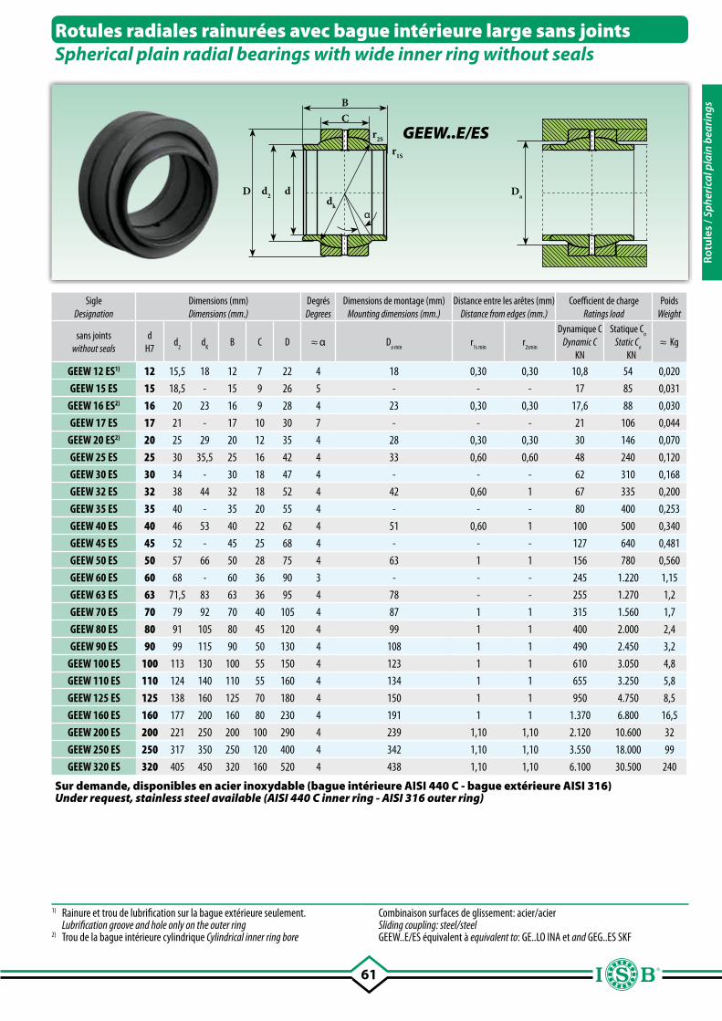
61
BC
r2S
r1S
dk
D dd2
α
Da
Rotules radiales rainurées avec bague intérieure large sans jointsSpherical plain radial bearings with wide inner ring without seals
SigleDesignation
Dimensions (mm)Dimensions (mm.)
DegrésDegrees
Dimensions de montage (mm)Mounting dimensions (mm.)
Distance entre les arêtes (mm)Distance from edges (mm.)
Coefficient de chargeRatings load
PoidsWeight
sans jointswithout seals
dH7
d2
dK
B C D ≈ α Da min
r1s min
r2smin
Dynamique CDynamic C
KN
Statique Co
Static Co
KN≈ Kg
GEEW 12 ES1) 12 15,5 18 12 7 22 4 18 0,30 0,30 10,8 54 0,020
GEEW 15 ES 15 18,5 - 15 9 26 5 - - - 17 85 0,031
GEEW 16 ES2) 16 20 23 16 9 28 4 23 0,30 0,30 17,6 88 0,030
GEEW 17 ES 17 21 - 17 10 30 7 - - - 21 106 0,044
GEEW 20 ES2) 20 25 29 20 12 35 4 28 0,30 0,30 30 146 0,070
GEEW 25 ES 25 30 35,5 25 16 42 4 33 0,60 0,60 48 240 0,120
GEEW 30 ES 30 34 - 30 18 47 4 - - - 62 310 0,168
GEEW 32 ES 32 38 44 32 18 52 4 42 0,60 1 67 335 0,200
GEEW 35 ES 35 40 - 35 20 55 4 - - - 80 400 0,253
GEEW 40 ES 40 46 53 40 22 62 4 51 0,60 1 100 500 0,340
GEEW 45 ES 45 52 - 45 25 68 4 - - - 127 640 0,481
GEEW 50 ES 50 57 66 50 28 75 4 63 1 1 156 780 0,560
GEEW 60 ES 60 68 - 60 36 90 3 - - - 245 1.220 1,15
GEEW 63 ES 63 71,5 83 63 36 95 4 78 - - 255 1.270 1,2
GEEW 70 ES 70 79 92 70 40 105 4 87 1 1 315 1.560 1,7
GEEW 80 ES 80 91 105 80 45 120 4 99 1 1 400 2.000 2,4
GEEW 90 ES 90 99 115 90 50 130 4 108 1 1 490 2.450 3,2
GEEW 100 ES 100 113 130 100 55 150 4 123 1 1 610 3.050 4,8
GEEW 110 ES 110 124 140 110 55 160 4 134 1 1 655 3.250 5,8
GEEW 125 ES 125 138 160 125 70 180 4 150 1 1 950 4.750 8,5
GEEW 160 ES 160 177 200 160 80 230 4 191 1 1 1.370 6.800 16,5
GEEW 200 ES 200 221 250 200 100 290 4 239 1,10 1,10 2.120 10.600 32
GEEW 250 ES 250 317 350 250 120 400 4 342 1,10 1,10 3.550 18.000 99
GEEW 320 ES 320 405 450 320 160 520 4 438 1,10 1,10 6.100 30.500 240
GEEW..E/ES
1) Rainure et trou de lubrification sur la bague extérieure seulement. Lubrification groove and hole only on the outer ring 2) Trou de la bague intérieure cylindrique Cylindrical inner ring bore
Combinaison surfaces de glissement: acier/acier Sliding coupling: steel/steelGEEW..E/ES équivalent à equivalent to: GE..LO INA et and GEG..ES SKF
Sur demande, disponibles en acier inoxydable (bague intérieure AISI 440 C - bague extérieure AISI 316)Under request, stainless steel available (AISI 440 C inner ring - AISI 316 outer ring)
Rotu
les
/ Sph
eric
al p
lain
bea
ring
s
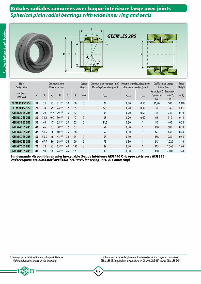
62
BC
r2S
r1S
dk
D dd2
α
Da
Rotules radiales rainurées avec bague intérieure large avec jointsSpherical plain radial bearings with wide inner ring and seals
GEEM..ES 2RS
SigleDesignation
Dimensions mmDimensions mm
DegrésDegrees
Dimensions de montage (mm)Mounting dimensions (mm.)
Distance entre les arêtes (mm)Distance from edges (mm.)
Coefficient de chargeRatings load
Poids Weight
avec jointswith seals
d d2
dK
B C D ≈ α Da min
r1s min
r2smin
Dynamique CDynamic C
KN
Statique Co
Static Co
KN≈ Kg
GEEM 17 ES 2RS1) 17 21 25 21±0,2 10 30 3 24 0,20 0,30 21,20 106 0,040
GEEM 20 ES 2RS1) 20 24 29 24±0,2 12 35 3 27,5 0,20 0,30 30 146 0,057
GEEM 25 ES 2RS 25 29 35,5 29±0,3 16 42 3 33 0,20 0,60 48 240 0,10
GEEM 30 ES 2RS 30 34,2 40,7 30±0,3 18 47 3 38 0,20 0,60 62 310 0,14
GEEM 35 ES 2RS 35 40 47 35±0,3 20 55 3 44,5 0,30 1 80 400 0,24
GEEM 40 ES 2RS 40 45 53 38±0,3 22 62 3 51 0,30 1 100 500 0,29
GEEM 45 ES 2RS 45 51,5 60 40±0,3 25 68 3 57 0,30 1 127 640 0,43
GEEM 50 ES 2RS 50 56,5 66 43±0,3 28 75 3 63 0,30 1 156 780 0,54
GEEM 60 ES 2RS 60 67,7 80 54±0,3 36 90 3 75 0,30 1 245 1.220 1,10
GEEM 70 ES 2RS 70 78 92 65±0,3 40 105 3 87 0,30 1 315 1.560 1,60
GEEM 80 ES 2RS 80 90 105 74±0,3 45 120 3 99 0,30 1 400 2.000 2,40
1) Sans gorge de lubrification sur la bague intérieure Without lubrication groove on the inner ring
Combinaison surfaces de glissement: acier/acier Sliding coupling: steel/steelGEEM..ES 2RS équivalent à equivalent to: GE..HO..2RS INA et and GEM..ES SKF
Sur demande, disponibles en acier inoxydable (bague intérieure AISI 440 C - bague extérieure AISI 316)Under request, stainless steel available (AISI 440 C inner ring - AISI 316 outer ring)
Rotu
les
/ Sph
eric
al p
lain
bea
ring
s
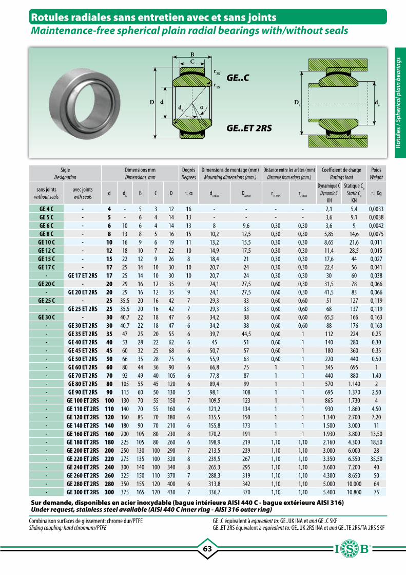
63
BC
r2S
r1S
D dαdk
Da da
Rotules radiales sans entretien avec et sans jointsMaintenance-free spherical plain radial bearings with/without seals
GE..C
SigleDesignation
Dimensions mmDimensions mm
DegrésDegrees
Dimensions de montage (mm)Mounting dimensions (mm.)
Distance entre les arêtes (mm)Distance from edges (mm.)
Coefficient de chargeRatings load
PoidsWeight
sans jointswithout seals
avec jointswith seals
d dK
B C D ≈ α da max
Da min
r1s min
r2smin
Dynamique CDynamic C
KN
Statique Co
Static Co
KN≈ Kg
GE 4 C - 4 - 5 3 12 16 - - - - 2,1 5,4 0,0033GE 5 C - 5 - 6 4 14 13 - - - - 3,6 9,1 0,0038GE 6 C - 6 10 6 4 14 13 8 9,6 0,30 0,30 3,6 9 0,0042GE 8 C - 8 13 8 5 16 15 10,2 12,5 0,30 0,30 5,85 14,6 0,0075
GE 10 C - 10 16 9 6 19 11 13,2 15,5 0,30 0,30 8,65 21,6 0,011GE 12 C - 12 18 10 7 22 10 14,9 17,5 0,30 0,30 11,4 28,5 0,015GE 15 C - 15 22 12 9 26 8 18,4 21 0,30 0,30 17,6 44 0,027GE 17 C - 17 25 14 10 30 10 20,7 24 0,30 0,30 22,4 56 0,041
- GE 17 ET 2RS 17 25 14 10 30 10 20,7 24 0,30 0,30 30 60 0,038GE 20 C - 20 29 16 12 35 9 24,1 27,5 0,60 0,30 31,5 78 0,066
- GE 20 ET 2RS 20 29 16 12 35 9 24,1 27,5 0,60 0,30 41,5 83 0,066GE 25 C - 25 35,5 20 16 42 7 29,3 33 0,60 0,60 51 127 0,119
- GE 25 ET 2RS 25 35,5 20 16 42 7 29,3 33 0,60 0,60 68 137 0,119GE 30 C - 30 40,7 22 18 47 6 34,2 38 0,60 0,60 65,5 166 0,163
- GE 30 ET 2RS 30 40,7 22 18 47 6 34,2 38 0,60 0,60 88 176 0,163- GE 35 ET 2RS 35 47 25 20 55 6 39,7 44,5 0,60 1 112 224 0,25- GE 40 ET 2RS 40 53 28 22 62 6 45 51 0,60 1 140 280 0,30- GE 45 ET 2RS 45 60 32 25 68 6 50,7 57 0,60 1 180 360 0,35- GE 50 ET 2RS 50 66 35 28 75 6 55,9 63 0,60 1 220 440 0,50- GE 60 ET 2RS 60 80 44 36 90 6 66,8 75 1 1 345 695 1- GE 70 ET 2RS 70 92 49 40 105 6 77,8 87 1 1 440 880 1,40- GE 80 ET 2RS 80 105 55 45 120 6 89,4 99 1 1 570 1.140 2- GE 90 ET 2RS 90 115 60 50 130 5 98,1 108 1 1 695 1.370 2,50- GE 100 ET 2RS 100 130 70 55 150 7 109,5 123 1 1 865 1.730 4- GE 110 ET 2RS 110 140 70 55 160 6 121,2 134 1 1 930 1.860 4,50- GE 120 ET 2RS 120 160 85 70 180 6 135,5 150 1 1 1.340 2.700 7,20- GE 140 ET 2RS 140 180 90 70 210 6 155,8 173 1 1 1.500 3.000 11- GE 160 ET 2RS 160 200 105 80 230 8 170,2 191 1 1 1.930 3.800 13,50- GE 180 ET 2RS 180 225 105 80 260 6 198,9 219 1,10 1,10 2.160 4.300 18,50- GE 200 ET 2RS 200 250 130 100 290 7 213,5 239 1,10 1,10 3.000 6.000 28- GE 220 ET 2RS 220 275 135 100 320 8 239,5 267 1,10 1,10 3.350 6.550 35,50- GE 240 ET 2RS 240 300 140 100 340 8 265,3 295 1,10 1,10 3.600 7.200 40- GE 260 ET 2RS 260 325 150 110 370 7 288,3 319 1,10 1,10 4.300 8.650 50- GE 280 ET 2RS 280 350 155 120 400 6 313,8 342 1,10 1,10 5.000 10.000 64- GE 300 ET 2RS 300 375 165 120 430 7 336,7 370 1,10 1,10 5.400 10.800 75
GE..ET 2RS
Combinaison surfaces de glissement: chrome dur/PTFE Sliding coupling: hard chromium/PTFE
GE..C équivalent à equivalent to: GE..UK INA et and GE..C SKFGE..ET 2RS équivalent à equivalent to: GE..UK 2RS INA et and GE..TE 2RS/TA 2RS SKF
Sur demande, disponibles en acier inoxydable (bague intérieure AISI 440 C - bague extérieure AISI 316)Under request, stainless steel available (AISI 440 C inner ring - AISI 316 outer ring)
Rotu
les
/ Sph
eric
al p
lain
bea
ring
s
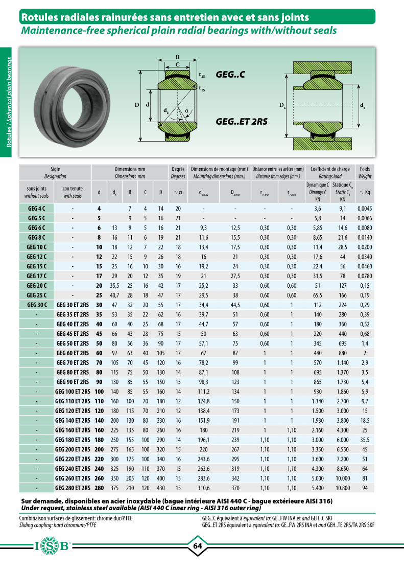
64
BC
r2S
r1S
D dαdk
Da da
Rotules radiales rainurées sans entretien avec et sans jointsMaintenance-free spherical plain radial bearings with/without seals
GEG..C
GEG..ET 2RS
SigleDesignation
Dimensions mmDimensions mm
DegrésDegrees
Dimensions de montage (mm)Mounting dimensions (mm.)
Distance entre les arêtes (mm)Distance from edges (mm.)
Coefficient de chargeRatings load
PoidsWeight
sans jointswithout seals
con tenutewith seals
d dK
B C D ≈ α da max
Da min
r1s min
r2smin
Dynamique CDinamyc C
KN
Statique Co
Static Co
KN≈ Kg
GEG 4 C - 4 7 4 14 20 - - - - 3,6 9,1 0,0045
GEG 5 C - 5 9 5 16 21 - - - - 5,8 14 0,0066
GEG 6 C - 6 13 9 5 16 21 9,3 12,5 0,30 0,30 5,85 14,6 0,0080
GEG 8 C - 8 16 11 6 19 21 11,6 15,5 0,30 0,30 8,65 21,6 0,0140
GEG 10 C - 10 18 12 7 22 18 13,4 17,5 0,30 0,30 11,4 28,5 0,0200
GEG 12 C - 12 22 15 9 26 18 16 21 0,30 0,30 17,6 44 0,0340
GEG 15 C - 15 25 16 10 30 16 19,2 24 0,30 0,30 22,4 56 0,0460
GEG 17 C - 17 29 20 12 35 19 21 27,5 0,30 0,30 31,5 78 0,0780
GEG 20 C - 20 35,5 25 16 42 17 25,2 33 0,60 0,60 51 127 0,15
GEG 25 C - 25 40,7 28 18 47 17 29,5 38 0,60 0,60 65,5 166 0,19
GEG 30 C GEG 30 ET 2RS 30 47 32 20 55 17 34,4 44,5 0,60 1 112 224 0,29
- GEG 35 ET 2RS 35 53 35 22 62 16 39,7 51 0,60 1 140 280 0,39
- GEG 40 ET 2RS 40 60 40 25 68 17 44,7 57 0,60 1 180 360 0,52
- GEG 45 ET 2RS 45 66 43 28 75 15 50 63 0,60 1 220 440 0,68
- GEG 50 ET 2RS 50 80 56 36 90 17 57,1 75 0,60 1 345 695 1,4
- GEG 60 ET 2RS 60 92 63 40 105 17 67 87 1 1 440 880 2
- GEG 70 ET 2RS 70 105 70 45 120 16 78,2 99 1 1 570 1.140 2,9
- GEG 80 ET 2RS 80 115 75 50 130 14 87,1 108 1 1 695 1.370 3,5
- GEG 90 ET 2RS 90 130 85 55 150 15 98,3 123 1 1 865 1.730 5,4
- GEG 100 ET 2RS 100 140 85 55 160 14 111,2 134 1 1 930 1.860 5,9
- GEG 110 ET 2RS 110 160 100 70 180 12 124,8 150 1 1 1.340 2.700 9,7
- GEG 120 ET 2RS 120 180 115 70 210 12 138,4 173 1 1 1.500 3.000 15
- GEG 140 ET 2RS 140 200 130 80 230 16 151,9 191 1 1 1.930 3.800 18,5
- GEG 160 ET 2RS 160 225 135 80 260 16 180 219 1 1,10 2.160 4.300 25
- GEG 180 ET 2RS 180 250 155 100 290 14 196,1 239 1,10 1,10 3.000 6.000 35,5
- GEG 200 ET 2RS 200 275 165 100 320 15 220 267 1,10 1,10 3.350 6.550 45
- GEG 220 ET 2RS 220 300 175 100 340 16 243,6 295 1,10 1,10 3.600 7.200 51
- GEG 240 ET 2RS 240 325 190 110 370 15 263,6 319 1,10 1,10 4.300 8.650 64
- GEG 260 ET 2RS 260 350 205 120 400 15 283,6 342 1,10 1,10 5.000 10.000 81
- GEG 280 ET 2RS 280 375 210 120 430 15 310,6 370 1,10 1,10 5.400 10.800 94
Combinaison surfaces de glissement: chrome dur/PTFE Sliding coupling: hard chromium/PTFE
GEG..C équivalent à equivalent to: GE..FW INA et and GEH..C SKFGEG..ET 2RS équivalent à equivalent to: GE..FW 2RS INA et and GEH..TE 2RS/TA 2RS SKF
Sur demande, disponibles en acier inoxydable (bague intérieure AISI 440 C - bague extérieure AISI 316)Under request, stainless steel available (AISI 440 C inner ring - AISI 316 outer ring)
Rotu
les
/ Sph
eric
al p
lain
bea
ring
s
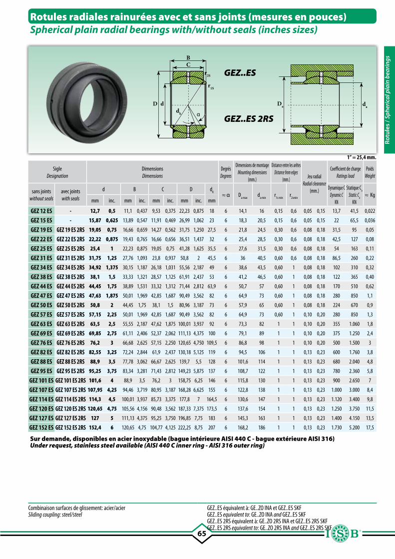
65
Da da
1” = 25,4 mm.
Sur demande, disponibles en acier inoxydable (bague intérieure AISI 440 C - bague extérieure AISI 316)Under request, stainless steel available (AISI 440 C inner ring - AISI 316 outer ring)
BC
dk
D d
α
r1S
r2S
Rotules radiales rainurées avec et sans joints (mesures en pouces)Spherical plain radial bearings with/without seals (inches sizes)
GEZ..ES
GEZ..ES 2RS
SigleDesignation
Dimensions Dimensions
DegrésDegrees
Dimensions de montageMounting dimensions
(mm.)
Distance entre les arêtesDistance from edges
(mm.) Jeu radialRadial clearance
(mm.)
Coefficient de chargeRatings load
PoidsWeight
sans jointswithout seals
avec jointswith seals
d B C D dK
≈ α Da max
da min
r1s min
r2smin
Dynamique CDynamic C
KN
Statique Co
Static Co
KN≈ Kg
mm inc. mm inc. mm inc. mm inc. mm
GEZ 12 ES - 12,7 0,5 11,1 0,437 9,53 0,375 22,23 0,875 18 6 14,1 16 0,15 0,6 0,05 0,15 13,7 41,5 0,022
GEZ 15 ES - 15,87 0,625 13,89 0,547 11,91 0,469 26,99 1,062 23 6 18,3 20,5 0,15 0,6 0,05 0,15 22 65,5 0,036
GEZ 19 ES GEZ 19 ES 2RS 19,05 0,75 16,66 0,659 14,27 0,562 31,75 1,250 27,5 6 21,8 24,5 0,30 0,6 0,08 0,18 31,5 95 0,05
GEZ 22 ES GEZ 22 ES 2RS 22,22 0,875 19,43 0,765 16,66 0,656 36,51 1,437 32 6 25,4 28,5 0,30 0,6 0,08 0,18 42,5 127 0,08
GEZ 25 ES GEZ 25 ES 2RS 25,4 1 22,23 0,875 19,05 0,75 41,28 1,625 35,5 6 27,6 31,5 0,30 0,6 0,08 0,18 54 163 0,11
GEZ 31 ES GEZ 31 ES 2RS 31,75 1,25 27,76 1,093 23,8 0,937 50,8 2 45,5 6 36 40,5 0,60 0,6 0,08 0,18 86,5 260 0,22
GEZ 34 ES GEZ 34 ES 2RS 34,92 1,375 30,15 1,187 26,18 1,031 55,56 2,187 49 6 38,6 43,5 0,60 1 0,08 0,18 102 310 0,32
GEZ 38 ES GEZ 38 ES 2RS 38,1 1,5 33,33 1,321 28,57 1,125 61,91 2,437 53 6 41,2 46,5 0,60 1 0,08 0,18 122 365 0,40
GEZ 44 ES GEZ 44 ES 2RS 44,45 1,75 38,89 1,531 33,32 1,312 71,44 2,812 63,9 6 50,7 57 0,60 1 0,08 0,18 170 510 0,62
GEZ 47 ES GEZ 47 ES 2RS 47,63 1,875 50,01 1,969 42,85 1,687 90,49 3,562 82 6 64,9 73 0,60 1 0,08 0,18 280 850 1,1
GEZ 50 ES GEZ 50 ES 2RS 50,8 2 44,45 1,75 38,1 1,5 80,96 3,187 73 6 57,9 65 0,60 1 0,08 0,18 224 670 0,9
GEZ 57 ES GEZ 57 ES 2RS 57,15 2,25 50,01 1,969 42,85 1,687 90,49 3,562 82 6 64,9 73 0,60 1 0,10 0,20 280 850 1,3
GEZ 63 ES GEZ 63 ES 2RS 63,5 2,5 55,55 2,187 47,62 1,875 100,01 3,937 92 6 73,3 82 1 1 0,10 0,20 355 1.060 1,8
GEZ 69 ES GEZ 69 ES 2RS 69,85 2,75 61,11 2,406 52,37 2,062 111,13 4,375 100 6 79,1 89 1 1 0,10 0,20 375 1.250 2,4
GEZ 76 ES GEZ 76 ES 2RS 76,2 3 66,68 2,625 57,15 2,250 120,65 4,750 109,5 6 86,8 98 1 1 0,10 0,20 500 1.500 3
GEZ 82 ES GEZ 82 ES 2RS 82,55 3,25 72,24 2,844 61,9 2,437 130,18 5,125 119 6 94,5 106 1 1 0,13 0,23 600 1.760 3,8
GEZ 88 ES GEZ 88 ES 2RS 88,9 3,5 77,78 3,062 66,67 2,625 139,7 5,5 128 6 101,6 114 1 1 0,13 0,23 680 2.040 4,8
GEZ 95 ES GEZ 95 ES 2RS 95,25 3,75 83,34 3,281 71,43 2,812 149,23 5,875 137 6 108,7 122 1 1 0,13 0,23 780 2.360 5,8
GEZ 101 ES GEZ 101 ES 2RS 101,6 4 88,9 3,5 76,2 3 158,75 6,25 146 6 115,8 130 1 1 0,13 0,23 900 2.650 7
GEZ 107 ES GEZ 107 ES 2RS 107,95 4,25 94,46 3,719 80,95 3,187 168,28 6,625 155 6 122,8 138 1 1 0,13 0,23 1.000 3.000 8,4
GEZ 114 ES GEZ 114 ES 2RS 114,3 4,5 100,01 3,937 85,73 3,375 177,8 7 164,5 6 130,6 147 1 1 0,13 0,23 1.120 3.400 9,8
GEZ 120 ES GEZ 120 ES 2RS 120,65 4,75 105,56 4,156 90,48 3,562 187,33 7,375 173,5 6 137,6 154 1 1 0,13 0,23 1.250 3.750 11,5
GEZ 127 ES GEZ 127 ES 2RS 127 5 111,13 4,375 95,25 3,750 196,85 7,75 183 6 145,3 163 1 1 0,13 0,23 1.400 4.150 13,5
GEZ 152 ES GEZ 152 ES 2RS 152,4 6 120,65 4,75 104,77 4,125 222,25 8,75 207 6 168,2 186 1 1 0,13 0,23 1.730 5.200 17,5
Combinaison surfaces de glissement: acier/acier Sliding coupling: steel/steel
GEZ..ES équivalent à: GE..ZO INA et GEZ..ES SKFGEZ..ES equivalent to: GE..ZO INA and GEZ..ES SKFGEZ..ES 2RS équivalent à: GE..ZO 2RS INA et GEZ..ES 2RS SKFGEZ..ES 2RS equivalent to: GE..ZO 2RS INA and GEZ..ES 2RS SKF
Rotu
les
/ Sph
eric
al p
lain
bea
ring
s
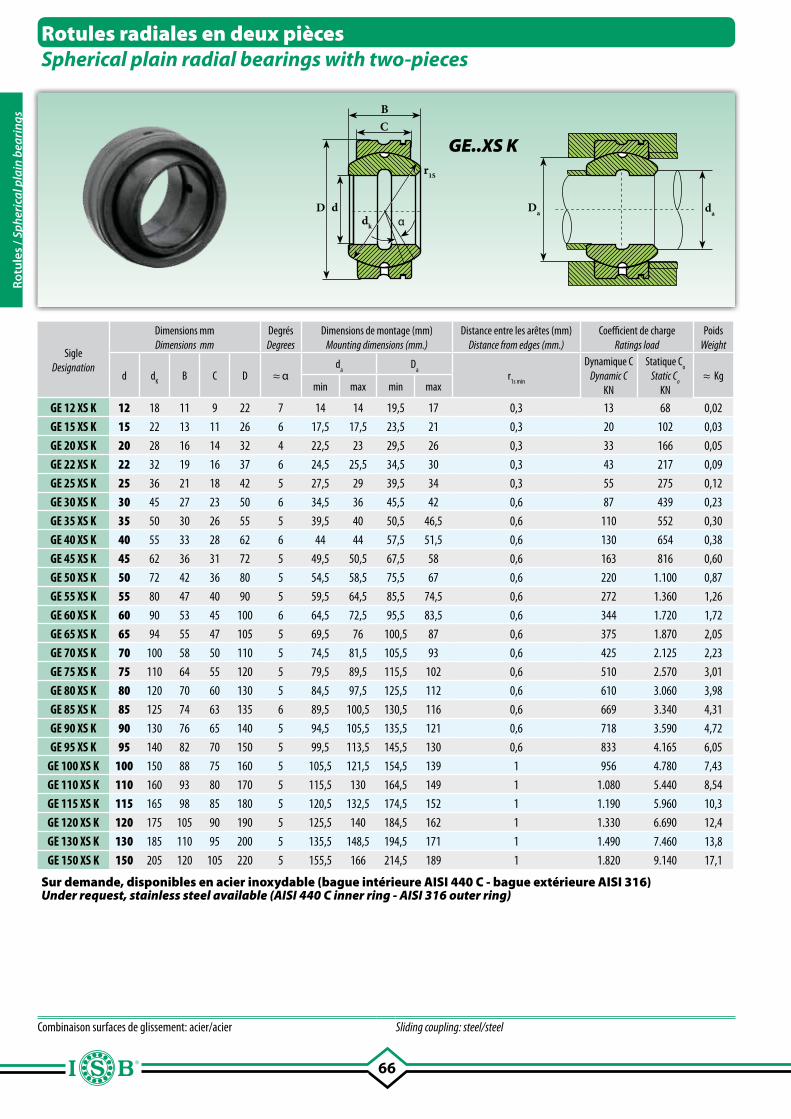
66
BC
dk
D dα
Da da
r1S
SigleDesignation
Dimensions mmDimensions mm
DegrésDegrees
Dimensions de montage (mm)Mounting dimensions (mm.)
Distance entre les arêtes (mm)Distance from edges (mm.)
Coefficient de chargeRatings load
PoidsWeight
d dK
B C D ≈ αd
a D
ar
1s min
Dynamique CDynamic C
KN
Statique Co
Static Co
KN≈ Kg
min max min max
GE 12 XS K 12 18 11 9 22 7 14 14 19,5 17 0,3 13 68 0,02
GE 15 XS K 15 22 13 11 26 6 17,5 17,5 23,5 21 0,3 20 102 0,03
GE 20 XS K 20 28 16 14 32 4 22,5 23 29,5 26 0,3 33 166 0,05
GE 22 XS K 22 32 19 16 37 6 24,5 25,5 34,5 30 0,3 43 217 0,09
GE 25 XS K 25 36 21 18 42 5 27,5 29 39,5 34 0,3 55 275 0,12
GE 30 XS K 30 45 27 23 50 6 34,5 36 45,5 42 0,6 87 439 0,23
GE 35 XS K 35 50 30 26 55 5 39,5 40 50,5 46,5 0,6 110 552 0,30
GE 40 XS K 40 55 33 28 62 6 44 44 57,5 51,5 0,6 130 654 0,38
GE 45 XS K 45 62 36 31 72 5 49,5 50,5 67,5 58 0,6 163 816 0,60
GE 50 XS K 50 72 42 36 80 5 54,5 58,5 75,5 67 0,6 220 1.100 0,87
GE 55 XS K 55 80 47 40 90 5 59,5 64,5 85,5 74,5 0,6 272 1.360 1,26
GE 60 XS K 60 90 53 45 100 6 64,5 72,5 95,5 83,5 0,6 344 1.720 1,72
GE 65 XS K 65 94 55 47 105 5 69,5 76 100,5 87 0,6 375 1.870 2,05
GE 70 XS K 70 100 58 50 110 5 74,5 81,5 105,5 93 0,6 425 2.125 2,23
GE 75 XS K 75 110 64 55 120 5 79,5 89,5 115,5 102 0,6 510 2.570 3,01
GE 80 XS K 80 120 70 60 130 5 84,5 97,5 125,5 112 0,6 610 3.060 3,98
GE 85 XS K 85 125 74 63 135 6 89,5 100,5 130,5 116 0,6 669 3.340 4,31
GE 90 XS K 90 130 76 65 140 5 94,5 105,5 135,5 121 0,6 718 3.590 4,72
GE 95 XS K 95 140 82 70 150 5 99,5 113,5 145,5 130 0,6 833 4.165 6,05
GE 100 XS K 100 150 88 75 160 5 105,5 121,5 154,5 139 1 956 4.780 7,43
GE 110 XS K 110 160 93 80 170 5 115,5 130 164,5 149 1 1.080 5.440 8,54
GE 115 XS K 115 165 98 85 180 5 120,5 132,5 174,5 152 1 1.190 5.960 10,3
GE 120 XS K 120 175 105 90 190 5 125,5 140 184,5 162 1 1.330 6.690 12,4
GE 130 XS K 130 185 110 95 200 5 135,5 148,5 194,5 171 1 1.490 7.460 13,8
GE 150 XS K 150 205 120 105 220 5 155,5 166 214,5 189 1 1.820 9.140 17,1
Rotules radiales en deux piècesSpherical plain radial bearings with two-pieces
GE..XS K
Combinaison surfaces de glissement: acier/acier Sliding coupling: steel/steel
Sur demande, disponibles en acier inoxydable (bague intérieure AISI 440 C - bague extérieure AISI 316)Under request, stainless steel available (AISI 440 C inner ring - AISI 316 outer ring)
Rotu
les
/ Sph
eric
al p
lain
bea
ring
s
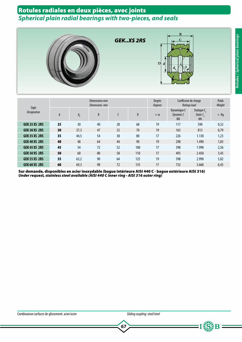
67
BC
D dαdk
Rotules radiales en deux pièces, avec jointsSpherical plain radial bearings with two-pieces, and seals
GEK..XS 2RS
SigleDesignation
Dimensions mmDimensions mm
DegrésDegrees
Coefficient de chargeRatings load
PoidsWeight
d dK
B C D ≈ αDynamique C
Dynamic CKN
Statique Co
Static Co
KN≈ Kg
GEK 25 XS 2RS 25 30 40 28 68 19 117 590 0,52
GEK 30 XS 2RS 30 37,3 47 32 70 19 163 813 0,79
GEK 35 XS 2RS 35 44,5 54 38 80 17 226 1.130 1,23
GEK 40 XS 2RS 40 48 64 44 90 19 298 1.490 1,83
GEK 45 XS 2RS 45 54 72 52 100 17 398 1.990 2,56
GEK 50 XS 2RS 50 60 80 58 110 17 493 2.450 3,43
GEK 55 XS 2RS 55 63,2 90 64 125 19 598 2.990 5,02
GEK 60 XS 2RS 60 69,3 98 72 135 17 732 3.660 6,43
Combinaison surfaces de glissement: acier/acier Sliding coupling: steel/steel
Sur demande, disponibles en acier inoxydable (bague intérieure AISI 440 C - bague extérieure AISI 316)Under request, stainless steel available (AISI 440 C inner ring - AISI 316 outer ring)
Rotu
les
/ Sph
eric
al p
lain
bea
ring
s
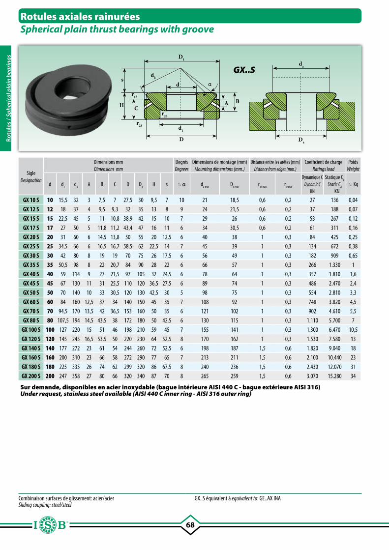
68
sdk
A
d
d1
D
α
D1
H CB
Da
da
r2S
r1S
r2S
Rotules axiales rainuréesSpherical plain thrust bearings with groove
GX..S
SigleDesignation
Dimensions mmDimensions mm
DegrésDegrees
Dimensions de montage (mm)Mounting dimensions (mm.)
Distance entre les arêtes (mm)Distance from edges (mm.)
Coefficient de chargeRatings load
PoidsWeight
d d1
dK
A B C D D1
H s ≈ α da min
Da min
r1s min
r2smin
Dynamique CDynamic C
KN
Statique Co
Static Co
KN≈ Kg
GX 10 S 10 15,5 32 3 7,5 7 27,5 30 9,5 7 10 21 18,5 0,6 0,2 27 136 0,04
GX 12 S 12 18 37 4 9,5 9,3 32 35 13 8 9 24 21,5 0,6 0,2 37 188 0,07
GX 15 S 15 22,5 45 5 11 10,8 38,9 42 15 10 7 29 26 0,6 0,2 53 267 0,12
GX 17 S 17 27 50 5 11,8 11,2 43,4 47 16 11 6 34 30,5 0,6 0,2 61 311 0,16
GX 20 S 20 31 60 6 14,5 13,8 50 55 20 12,5 6 40 38 1 0,3 84 425 0,25
GX 25 S 25 34,5 66 6 16,5 16,7 58,5 62 22,5 14 7 45 39 1 0,3 134 672 0,38
GX 30 S 30 42 80 8 19 19 70 75 26 17,5 6 56 49 1 0,3 182 909 0,65
GX 35 S 35 50,5 98 8 22 20,7 84 90 28 22 6 66 57 1 0,3 266 1.330 1
GX 40 S 40 59 114 9 27 21,5 97 105 32 24,5 6 78 64 1 0,3 357 1.810 1,6
GX 45 S 45 67 130 11 31 25,5 110 120 36,5 27,5 6 89 74 1 0,3 486 2.470 2,4
GX 50 S 50 70 140 10 33 30,5 120 130 42,5 30 5 98 75 1 0,3 554 2.810 3,3
GX 60 S 60 84 160 12,5 37 34 140 150 45 35 7 108 92 1 0,3 748 3.820 4,5
GX 70 S 70 94,5 170 13,5 42 36,5 153 160 50 35 6 121 102 1 0,3 902 4.610 5,5
GX 80 S 80 107,5 194 14,5 43,5 38 172 180 50 42,5 6 130 115 1 0,3 1.110 5.700 7
GX 100 S 100 127 220 15 51 46 198 210 59 45 7 155 141 1 0,3 1.300 6.470 10,5
GX 120 S 120 145 245 16,5 53,5 50 220 230 64 52,5 8 170 162 1 0,3 1.530 7.580 13
GX 140 S 140 177 272 23 61 54 244 260 72 52,5 6 198 187 1,5 0,6 1.820 9.040 18
GX 160 S 160 200 310 23 66 58 272 290 77 65 7 213 211 1,5 0,6 2.100 10.440 23
GX 180 S 180 225 335 26 74 62 299 320 86 67,5 8 240 236 1,5 0,6 2.430 12.070 31
GX 200 S 200 247 358 27 80 66 320 340 87 70 8 265 259 1,5 0,6 3.070 15.280 34
Combinaison surfaces de glissement: acier/acier Sliding coupling: steel/steel
GX..S équivalent à equivalent to: GE..AX INA
Sur demande, disponibles en acier inoxydable (bague intérieure AISI 440 C - bague extérieure AISI 316)Under request, stainless steel available (AISI 440 C inner ring - AISI 316 outer ring)
Rotu
les
/ Sph
eric
al p
lain
bea
ring
s
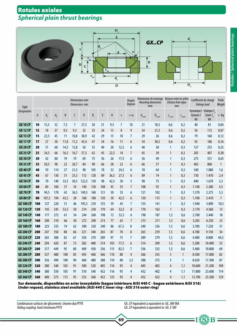
69
sdk
d
d1
D
α
D1
H CB
Da
da E
r2S
r1S
r2S
SigleDesignation
Dimensions mmDimensions mm
DegrésDegrees
Dimensions de montageMounting dimensions
mm
Distance entre les arêtesDistance from edges
mm
Coefficient de chargeRatings load
PoidsWeight
d d1
dK
B C D D1
E H s ≈ α da min
Da min
r1s min
r2smin
Dynamique CDynamic C
KN
Statique Co
Static Co
KN≈ Kg
GX 10 CP 10 15,5 32 7,5 7 27,5 30 21 9,5 7 10 21 18,5 0,6 0,2 40 81 0,04
GX 12 CP 12 18 37 9,5 9,3 32 35 24 13 8 9 24 21,5 0,6 0,2 56 112 0,07
GX 15 CP 15 22,5 45 11 10,8 38,9 42 29 15 10 7 29 26 0,6 0,2 79 160 0,12
GX 17 CP 17 27 50 11,8 11,2 43,4 47 34 16 11 6 34 30,5 0,6 0,2 92 186 0,16
GX 20 CP 20 31 60 14,5 13,8 50 55 40 20 12,5 6 40 38 1 0,3 127 255 0,25
GX 25 CP 25 34,5 66 16,5 16,7 57,5 62 45 22,5 14 7 45 39 1 0,3 203 407 0,38
GX 30 CP 30 42 80 19 19 69 75 56 26 17,5 6 56 49 1 0,3 275 551 0,65
GX 35 CP 35 50,5 98 22 20,7 84 90 66 28 22 6 66 57 1 0,3 403 806 1
GX 40 CP 40 59 114 27 21,5 98 105 78 32 24,5 6 78 64 1 0,3 540 1.080 1,6
GX 45 CP 45 67 130 31 25,5 112 120 89 36,5 27,5 6 89 74 1 0,3 730 1.470 2,4
GX 50 CP 50 70 140 33,5 30,5 122,5 130 98 42,5 30 5 98 75 1 0,3 840 1.670 3,3
GX 60 CP 60 84 160 37 34 140 150 108 45 35 7 108 92 1 0,3 1.140 2.280 4,5
GX 70 CP 70 94,5 170 42 36,5 149,5 160 121 50 35 6 121 102 1 0,3 1.370 2.275 5,5
GX 80 CP 80 107,5 194 43,5 38 168 180 130 50 42,5 6 130 115 1 0,3 1.700 3.410 7
GX 100 CP 100 127 220 51 46 195,5 210 155 59 45 7 155 141 1 0,3 1.940 3.890 10,5
GX 120 CP 120 145 245 53,5 50 214 230 170 64 52,5 8 170 162 1 0,3 2.170 4.560 13
GX 140 CP 140 177 272 61 54 244 260 198 72 52,5 6 198 187 1,5 0,6 2.700 5.440 18
GX 160 CP 160 200 310 66 58 272 290 213 77 65 7 213 211 1,5 0,6 3.265 6.250 23
GX 180 CP 180 225 335 74 62 300 320 240 86 67,5 8 240 236 1,5 0,6 3.700 7.220 31
GX 200 CP 200 247 358 80 66 321 340 265 87 70 8 265 259 1,5 0,6 4.780 9.150 34
GX 220 CP 220 265 388 82 67 350 370 289 97 75 7 289 279 1,5 0,6 4.400 8.800 44,5
GX 240 CP 240 294 420 87 73 382 400 314 103 77,5 6 314 309 1,5 0,6 5.200 10.400 55
GX 260 CP 260 317 449 95 80 409 430 336 115 82,5 7 336 332 1,5 0,6 5.400 10.800 69
GX 280 CP 280 337 480 100 85 445 460 366 110 80 4 366 355 3 1 8.500 17.000 82
GX 300 CP 300 356 490 100 90 460 480 388 110 80 3,5 388 375 3 1 8.650 17.300 87
GX 320 CP 320 380 540 105 91 500 520 405 116 95 4 405 402 4 1,1 10.600 21.200 109
GX 340 CP 340 380 550 105 91 510 540 432 116 95 4 432 402 4 1,1 11.800 23.600 114
GX 360 CP 360 400 575 115 95 535 560 452 125 95 4 452 422 4 1,1 12.700 25.500 129
Rotules axialesSpherical plain thrust bearings
Combinaison surfaces de glissement: chrome dur/PTFE Sliding coupling: hard chromium/PTFE
GX..CP équivalent à equivalent to: GE..AW INAGX..CP équivalent à equivalent to: GX..F SKF
GX..CP
Sur demande, disponibles en acier inoxydable (bague intérieure AISI 440 C - bague extérieure AISI 316)Under request, stainless steel available (AISI 440 C inner ring - AISI 316 outer ring)
Rotu
les
/ Sph
eric
al p
lain
bea
ring
s
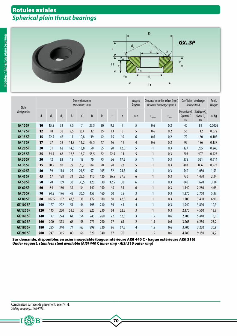
70
sdk
d
d1
D
α
D1
H CB
r2S
r1S
r2S
Rotules axialesSpherical plain thrust bearings
GX..SP
Combinaison surfaces de glissement: acier/PTFE Sliding coupling: steel/PTFE
SigleDesignation
Dimensions mmDimensions mm
Degrés Degrees
Distance entre les arêtes (mm)Distance from edges (mm.)
Coefficient de chargeRatings load
PoidsWeight
d d1
dK
B C D D1
H s ≈ α r1s min
r2smin
Dynamique CDynamic C
KN
Statique Co
Static Co
KN≈ Kg
GX 10 SP 10 15,5 32 7,5 7 27,5 30 9,5 7 5 0,6 0,2 40 81 0,0026
GX 12 SP 12 18 38 9,5 9,3 32 35 13 8 5 0,6 0,2 56 112 0,072
GX 15 SP 15 22,5 46 11 10,8 39 42 15 10 6 0,6 0,2 79 160 0,108
GX 17 SP 17 27 52 11,8 11,2 43,5 47 16 11 4 0,6 0,2 92 186 0,137
GX 20 SP 20 31 62 14,5 13,8 50 55 20 12,5 5 1 0,3 127 255 0,246
GX 25 SP 25 34,5 68 16,5 16,7 58,5 62 22,5 14 5 1 0,3 203 407 0,425
GX 30 SP 30 42 82 19 19 70 75 26 17,5 5 1 0,3 275 551 0,614
GX 35 SP 35 50,5 98 22 20,7 84 90 28 22 5 1 0,3 403 806 0,973
GX 40 SP 40 59 114 27 21,5 97 105 32 24,5 6 1 0,3 540 1.080 1,59
GX 45 SP 45 67 128 31 25,5 110 120 36,5 27,5 6 1 0,3 730 1.470 2,24
GX 50 SP 50 70 139 33 30,5 120 130 42,5 30 6 1 0,3 840 1.670 3,14
GX 60 SP 60 84 160 37 34 140 150 45 35 6 1 0,3 1.140 2.280 4,63
GX 70 SP 70 94,5 176 42 36,5 153 160 50 35 3 1 0,3 1.370 2.750 5,37
GX 80 SP 80 107,5 197 43,5 38 172 180 50 42,5 4 1 0,3 1.700 3.410 6,91
GX 100 SP 100 127 222 51 46 198 210 59 45 4 1 0,3 1.940 3.890 10,9
GX 120 SP 120 145 250 53,5 50 220 230 64 52,5 3 1 0,3 2.170 4.560 13,9
GX 140 SP 140 177 274 61 54 243 260 72 52,5 3 1,5 0,6 2.700 5.440 18,1
GX 160 SP 160 200 313 66 58 271 290 77 65 2 1,5 0,6 3.265 6.250 23,2
GX 180 SP 180 225 340 74 62 299 320 86 67,5 4 1,5 0,6 3.700 7.220 30,9
GX 200 SP 200 247 365 80 66 320 340 87 70 1 1,5 0,6 4.780 9.150 34,2
Sur demande, disponibles en acier inoxydable (bague intérieure AISI 440 C - bague extérieure AISI 316)Under request, stainless steel available (AISI 440 C inner ring - AISI 316 outer ring)
Rotu
les
/ Sph
eric
al p
lain
bea
ring
s
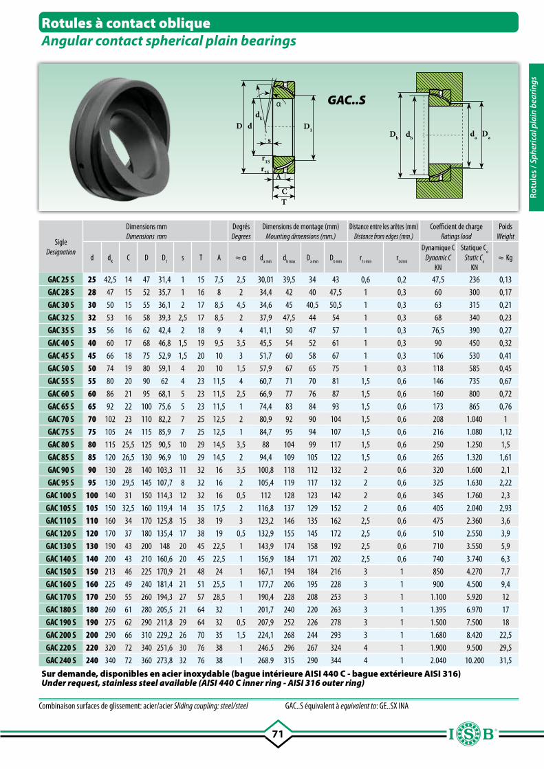
71
C
r1S
D ddk
s
A
T
Db dbda Da
α
r2S
D1
SigleDesignation
Dimensions mmDimensions mm
DegrésDegrees
Dimensions de montage (mm)Mounting dimensions (mm.)
Distance entre les arêtes (mm)Distance from edges (mm.)
Coefficient de chargeRatings load
PoidsWeight
d dK
C D D1
s T A ≈ α da min
db max
Da min
Db min
r1s min
r2smin
Dynamique CDynamic C
KN
Statique Co
Static Co
KN≈ Kg
GAC 25 S 25 42,5 14 47 31,4 1 15 7,5 2,5 30,01 39,5 34 43 0,6 0,2 47,5 236 0,13GAC 28 S 28 47 15 52 35,7 1 16 8 2 34,4 42 40 47,5 1 0,3 60 300 0,17GAC 30 S 30 50 15 55 36,1 2 17 8,5 4,5 34,6 45 40,5 50,5 1 0,3 63 315 0,21GAC 32 S 32 53 16 58 39,3 2,5 17 8,5 2 37,9 47,5 44 54 1 0,3 68 340 0,23GAC 35 S 35 56 16 62 42,4 2 18 9 4 41,1 50 47 57 1 0,3 76,5 390 0,27GAC 40 S 40 60 17 68 46,8 1,5 19 9,5 3,5 45,5 54 52 61 1 0,3 90 450 0,32GAC 45 S 45 66 18 75 52,9 1,5 20 10 3 51,7 60 58 67 1 0,3 106 530 0,41GAC 50 S 50 74 19 80 59,1 4 20 10 1,5 57,9 67 65 75 1 0,3 118 585 0,45GAC 55 S 55 80 20 90 62 4 23 11,5 4 60,7 71 70 81 1,5 0,6 146 735 0,67GAC 60 S 60 86 21 95 68,1 5 23 11,5 2,5 66,9 77 76 87 1,5 0,6 160 800 0,72GAC 65 S 65 92 22 100 75,6 5 23 11,5 1 74,4 83 84 93 1,5 0,6 173 865 0,76GAC 70 S 70 102 23 110 82,2 7 25 12,5 2 80,9 92 90 104 1,5 0,6 208 1.040 1GAC 75 S 75 105 24 115 85,9 7 25 12,5 1 84,7 95 94 107 1,5 0,6 216 1.080 1,12GAC 80 S 80 115 25,5 125 90,5 10 29 14,5 3,5 88 104 99 117 1,5 0,6 250 1.250 1,5GAC 85 S 85 120 26,5 130 96,9 10 29 14,5 2 94,4 109 105 122 1,5 0,6 265 1.320 1,61GAC 90 S 90 130 28 140 103,3 11 32 16 3,5 100,8 118 112 132 2 0,6 320 1.600 2,1GAC 95 S 95 130 29,5 145 107,7 8 32 16 2 105,4 119 117 132 2 0,6 325 1.630 2,22
GAC 100 S 100 140 31 150 114,3 12 32 16 0,5 112 128 123 142 2 0,6 345 1.760 2,3GAC 105 S 105 150 32,5 160 119,4 14 35 17,5 2 116,8 137 129 152 2 0,6 405 2.040 2,93GAC 110 S 110 160 34 170 125,8 15 38 19 3 123,2 146 135 162 2,5 0,6 475 2.360 3,6GAC 120 S 120 170 37 180 135,4 17 38 19 0,5 132,9 155 145 172 2,5 0,6 510 2.550 3,9GAC 130 S 130 190 43 200 148 20 45 22,5 1 143,9 174 158 192 2,5 0,6 710 3.550 5,9GAC 140 S 140 200 43 210 160,6 20 45 22,5 1 156,9 184 171 202 2,5 0,6 740 3.740 6,3GAC 150 S 150 213 46 225 170,9 21 48 24 1 167,1 194 184 216 3 1 850 4.270 7,7GAC 160 S 160 225 49 240 181,4 21 51 25,5 1 177,7 206 195 228 3 1 900 4.500 9,4GAC 170 S 170 250 55 260 194,3 27 57 28,5 1 190,4 228 208 253 3 1 1.100 5.920 12GAC 180 S 180 260 61 280 205,5 21 64 32 1 201,7 240 220 263 3 1 1.395 6.970 17GAC 190 S 190 275 62 290 211,8 29 64 32 0,5 207,9 252 226 278 3 1 1.500 7.500 18GAC 200 S 200 290 66 310 229,2 26 70 35 1,5 224,1 268 244 293 3 1 1.680 8.420 22,5GAC 220 S 220 320 72 340 251,6 30 76 38 1 246.5 296 267 324 4 1 1.900 9.500 29,5GAC 240 S 240 340 72 360 273,8 32 76 38 1 268.9 315 290 344 4 1 2.040 10.200 31,5
Rotules à contact obliqueAngular contact spherical plain bearings
GAC..S
Combinaison surfaces de glissement: acier/acier Sliding coupling: steel/steel GAC..S équivalent à equivalent to: GE..SX INA
Sur demande, disponibles en acier inoxydable (bague intérieure AISI 440 C - bague extérieure AISI 316)Under request, stainless steel available (AISI 440 C inner ring - AISI 316 outer ring)
Rotu
les
/ Sph
eric
al p
lain
bea
ring
s
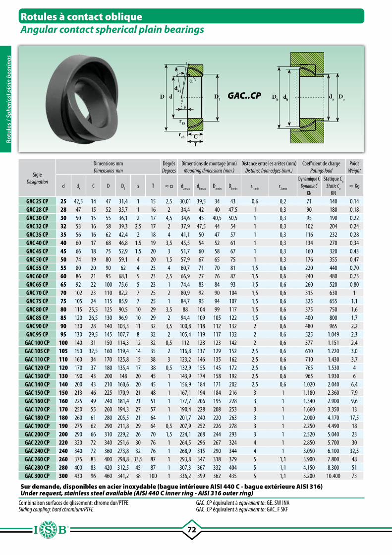
72
Rotules à contact obliqueAngular contact spherical plain bearings
Cr2S
r1S
D ddk
s
T
Db dbda Da
α
D1
Combinaison surfaces de glissement: chrome dur/PTFE Sliding coupling: hard chromium/PTFE
GAC..CP équivalent à equivalent to: GE..SW INA GAC..CP équivalent à equivalent to: GAC..F SKF
SigleDesignation
Dimensions mmDimensions mm
DegrésDegrees
Dimensions de montage (mm)Mounting dimensions (mm.)
Distance entre les arêtes (mm)Distance from edges (mm.)
Coefficient de chargeRatings load
PoidsWeight
d dK
C D D1
s T ≈ α da max
db max
Da min
Db min
r1s min
r2smin
Dynamique CDynamic C
KN
Statique Co
Static Co
KN≈ Kg
GAC 25 CP 25 42,5 14 47 31,4 1 15 2,5 30,01 39,5 34 43 0,6 0,2 71 140 0,14GAC 28 CP 28 47 15 52 35,7 1 16 2 34,4 42 40 47,5 1 0,3 90 180 0,18GAC 30 CP 30 50 15 55 36,1 2 17 4,5 34,6 45 40,5 50,5 1 0,3 95 190 0,22GAC 32 CP 32 53 16 58 39,3 2,5 17 2 37,9 47,5 44 54 1 0,3 102 204 0,24GAC 35 CP 35 56 16 62 42,4 2 18 4 41,1 50 47 57 1 0,3 116 232 0,28GAC 40 CP 40 60 17 68 46,8 1,5 19 3,5 45,5 54 52 61 1 0,3 134 270 0,34GAC 45 CP 45 66 18 75 52,9 1,5 20 3 51,7 60 58 67 1 0,3 160 320 0,43GAC 50 CP 50 74 19 80 59,1 4 20 1,5 57,9 67 65 75 1 0,3 176 355 0,47GAC 55 CP 55 80 20 90 62 4 23 4 60,7 71 70 81 1,5 0,6 220 440 0,70GAC 60 CP 60 86 21 95 68,1 5 23 2,5 66,9 77 76 87 1,5 0,6 240 480 0,75GAC 65 CP 65 92 22 100 75,6 5 23 1 74,4 83 84 93 1,5 0,6 260 520 0,80GAC 70 CP 70 102 23 110 82,2 7 25 2 80,9 92 90 104 1,5 0,6 315 630 1GAC 75 CP 75 105 24 115 85,9 7 25 1 84,7 95 94 107 1,5 0,6 325 655 1,1GAC 80 CP 80 115 25,5 125 90,5 10 29 3,5 88 104 99 117 1,5 0,6 375 750 1,6GAC 85 CP 85 120 26,5 130 96,9 10 29 2 94,4 109 105 122 1,5 0,6 400 800 1,7GAC 90 CP 90 130 28 140 103,3 11 32 3,5 100,8 118 112 132 2 0,6 480 965 2,2GAC 95 CP 95 130 29,5 145 107,7 8 32 2 105,4 119 117 132 2 0,6 525 1.049 2,3
GAC 100 CP 100 140 31 150 114,3 12 32 0,5 112 128 123 142 2 0,6 577 1.151 2,4GAC 105 CP 105 150 32,5 160 119,4 14 35 2 116,8 137 129 152 2,5 0,6 610 1.220 3,0GAC 110 CP 110 160 34 170 125,8 15 38 3 123,2 146 135 162 2,5 0,6 710 1.430 3,7GAC 120 CP 120 170 37 180 135,4 17 38 0,5 132,9 155 145 172 2,5 0,6 765 1.530 4GAC 130 CP 130 190 43 200 148 20 45 1 143,9 174 158 192 2,5 0,6 965 1.930 6GAC 140 CP 140 200 43 210 160,6 20 45 1 156,9 184 171 202 2,5 0,6 1.020 2.040 6,4GAC 150 CP 150 213 46 225 170,9 21 48 1 167,1 194 184 216 3 1 1.180 2.360 7,9GAC 160 CP 160 225 49 240 181,4 21 51 1 177,7 206 195 228 3 1 1.340 2.900 9,6GAC 170 CP 170 250 55 260 194,3 27 57 1 190,4 228 208 253 3 1 1.660 3.350 13GAC 180 CP 180 260 61 280 205,5 21 64 1 201,7 240 220 263 3 1 2.000 4.170 17,5GAC 190 CP 190 275 62 290 211,8 29 64 0,5 207,9 252 226 278 3 1 2.250 4.490 18GAC 200 CP 200 290 66 310 229,2 26 70 1,5 224,1 268 244 293 3 1 2.520 5.040 23GAC 220 CP 220 320 72 340 251,6 30 76 1 264,5 296 267 324 4 1 2.850 5.700 30GAC 240 CP 240 340 72 360 273,8 32 76 1 268,9 315 290 344 4 1 3.050 6.100 32,5GAC 260 CP 260 375 83 400 298,8 33,5 87 1 293,8 347 318 379 5 1,1 3.900 7.800 48GAC 280 CP 280 400 83 420 312,5 45 87 1 307,3 367 332 404 5 1,1 4.150 8.300 51GAC 300 CP 300 430 96 460 341,2 38 100 1 336,2 399 362 435 5 1,1 5.200 10.400 73
Sur demande, disponibles en acier inoxydable (bague intérieure AISI 440 C - bague extérieure AISI 316)Under request, stainless steel available (AISI 440 C inner ring - AISI 316 outer ring)
GAC..CP
Rotu
les
/ Sph
eric
al p
lain
bea
ring
s
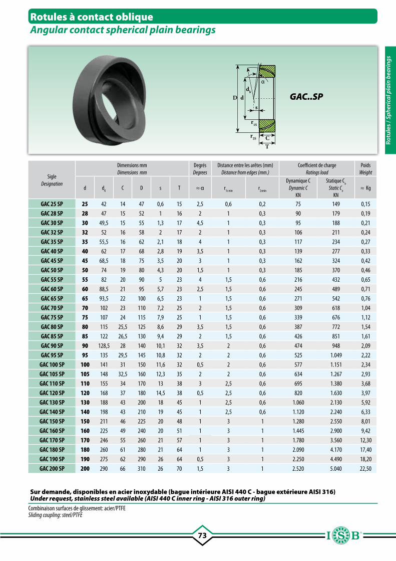
73
Sur demande, disponibles en acier inoxydable (bague intérieure AISI 440 C - bague extérieure AISI 316)Under request, stainless steel available (AISI 440 C inner ring - AISI 316 outer ring)
Cr2S
r1S
D ddk
s
T
α
SigleDesignation
Dimensions mmDimensions mm
DegrésDegrees
Distance entre les arêtes (mm)Distance from edges (mm.)
Coefficient de chargeRatings load
PoidsWeight
d dK
C D s T ≈ α r1s min
r2smin
Dynamique CDynamic C
KN
Statique Co
Static Co
KN≈ Kg
GAC 25 SP 25 42 14 47 0,6 15 2,5 0,6 0,2 75 149 0,15
GAC 28 SP 28 47 15 52 1 16 2 1 0,3 90 179 0,19
GAC 30 SP 30 49,5 15 55 1,3 17 4,5 1 0,3 95 188 0,21
GAC 32 SP 32 52 16 58 2 17 2 1 0,3 106 211 0,24
GAC 35 SP 35 55,5 16 62 2,1 18 4 1 0,3 117 234 0,27
GAC 40 SP 40 62 17 68 2,8 19 3,5 1 0,3 139 277 0,33
GAC 45 SP 45 68,5 18 75 3,5 20 3 1 0,3 162 324 0,42
GAC 50 SP 50 74 19 80 4,3 20 1,5 1 0,3 185 370 0,46
GAC 55 SP 55 82 20 90 5 23 4 1,5 0,6 216 432 0,65
GAC 60 SP 60 88,5 21 95 5,7 23 2,5 1,5 0,6 245 489 0,71
GAC 65 SP 65 93,5 22 100 6,5 23 1 1,5 0,6 271 542 0,76
GAC 70 SP 70 102 23 110 7,2 25 2 1,5 0,6 309 618 1,04
GAC 75 SP 75 107 24 115 7,9 25 1 1,5 0,6 339 676 1,12
GAC 80 SP 80 115 25,5 125 8,6 29 3,5 1,5 0,6 387 772 1,54
GAC 85 SP 85 122 26,5 130 9,4 29 2 1,5 0,6 426 851 1,61
GAC 90 SP 90 128,5 28 140 10,1 32 3,5 2 0,6 474 948 2,09
GAC 95 SP 95 135 29,5 145 10,8 32 2 2 0,6 525 1.049 2,22
GAC 100 SP 100 141 31 150 11,6 32 0,5 2 0,6 577 1.151 2,34
GAC 105 SP 105 148 32,5 160 12,3 35 2 2 0,6 634 1.267 2,93
GAC 110 SP 110 155 34 170 13 38 3 2,5 0,6 695 1.380 3,68
GAC 120 SP 120 168 37 180 14,5 38 0,5 2,5 0,6 820 1.630 3,97
GAC 130 SP 130 188 43 200 18 45 1 2,5 0,6 1.060 2.130 5,92
GAC 140 SP 140 198 43 210 19 45 1 2,5 0,6 1.120 2.240 6,33
GAC 150 SP 150 211 46 225 20 48 1 3 1 1.280 2.550 8,01
GAC 160 SP 160 225 49 240 20 51 1 3 1 1.445 2.900 9,42
GAC 170 SP 170 246 55 260 21 57 1 3 1 1.780 3.560 12,30
GAC 180 SP 180 260 61 280 21 64 1 3 1 2.090 4.170 17,40
GAC 190 SP 190 275 62 290 26 64 0,5 3 1 2.250 4.490 18,20
GAC 200 SP 200 290 66 310 26 70 1,5 3 1 2.520 5.040 22,50
Combinaison surfaces de glissement: acier/PTFE Sliding coupling: steel/PTFE
Rotules à contact obliqueAngular contact spherical plain bearings
GAC..SP
Rotu
les
/ Sph
eric
al p
lain
bea
ring
s
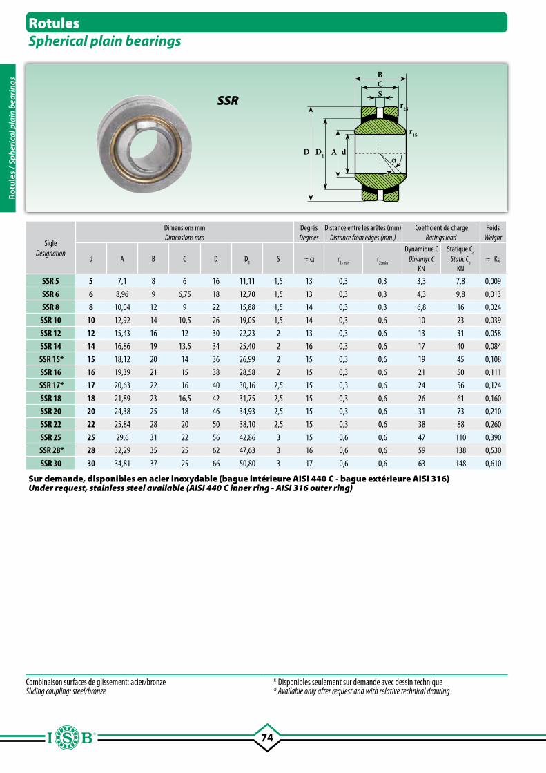
74
BC
D dα
AD1
S
r1S
r2S
RotulesSpherical plain bearings
SSR
SigleDesignation
Dimensions mmDimensions mm
DegrésDegrees
Distance entre les arêtes (mm)Distance from edges (mm.)
Coefficient de chargeRatings load
PoidsWeight
d A B C D D1
S ≈ α r1s min
r2smin
Dynamique CDinamyc C
KN
Statique Co
Static Co
KN≈ Kg
SSR 5 5 7,1 8 6 16 11,11 1,5 13 0,3 0,3 3,3 7,8 0,009
SSR 6 6 8,96 9 6,75 18 12,70 1,5 13 0,3 0,3 4,3 9,8 0,013
SSR 8 8 10,04 12 9 22 15,88 1,5 14 0,3 0,3 6,8 16 0,024
SSR 10 10 12,92 14 10,5 26 19,05 1,5 14 0,3 0,6 10 23 0,039
SSR 12 12 15,43 16 12 30 22,23 2 13 0,3 0,6 13 31 0,058
SSR 14 14 16,86 19 13,5 34 25,40 2 16 0,3 0,6 17 40 0,084
SSR 15* 15 18,12 20 14 36 26,99 2 15 0,3 0,6 19 45 0,108
SSR 16 16 19,39 21 15 38 28,58 2 15 0,3 0,6 21 50 0,111
SSR 17* 17 20,63 22 16 40 30,16 2,5 15 0,3 0,6 24 56 0,124
SSR 18 18 21,89 23 16,5 42 31,75 2,5 15 0,3 0,6 26 61 0,160
SSR 20 20 24,38 25 18 46 34,93 2,5 15 0,3 0,6 31 73 0,210
SSR 22 22 25,84 28 20 50 38,10 2,5 15 0,3 0,6 38 88 0,260
SSR 25 25 29,6 31 22 56 42,86 3 15 0,6 0,6 47 110 0,390
SSR 28* 28 32,29 35 25 62 47,63 3 16 0,6 0,6 59 138 0,530
SSR 30 30 34,81 37 25 66 50,80 3 17 0,6 0,6 63 148 0,610
Combinaison surfaces de glissement: acier/bronze Sliding coupling: steel/bronze
* Disponibles seulement sur demande avec dessin technique* Available only after request and with relative technical drawing
Sur demande, disponibles en acier inoxydable (bague intérieure AISI 440 C - bague extérieure AISI 316)Under request, stainless steel available (AISI 440 C inner ring - AISI 316 outer ring)
Rotu
les
/ Sph
eric
al p
lain
bea
ring
s
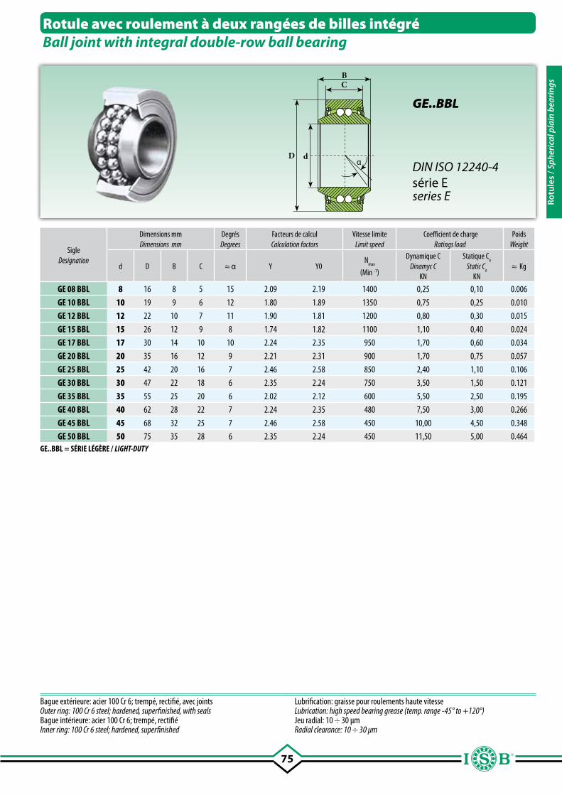
75
BC
D dα
SigleDesignation
Dimensions mmDimensions mm
DegrésDegrees
Facteurs de calculCalculation factors
Vitesse limiteLimit speed
Coefficient de chargeRatings load
PoidsWeight
d D B C ≈ α Y Y0N
max
(Min -1)
Dynamique CDinamyc C
KN
Statique Co
Static Co
KN≈ Kg
GE 08 BBL 8 16 8 5 15 2.09 2.19 1400 0,25 0,10 0.006
GE 10 BBL 10 19 9 6 12 1.80 1.89 1350 0,75 0,25 0.010
GE 12 BBL 12 22 10 7 11 1.90 1.81 1200 0,80 0,30 0.015
GE 15 BBL 15 26 12 9 8 1.74 1.82 1100 1,10 0,40 0.024
GE 17 BBL 17 30 14 10 10 2.24 2.35 950 1,70 0,60 0.034
GE 20 BBL 20 35 16 12 9 2.21 2.31 900 1,70 0,75 0.057
GE 25 BBL 25 42 20 16 7 2.46 2.58 850 2,40 1,10 0.106
GE 30 BBL 30 47 22 18 6 2.35 2.24 750 3,50 1,50 0.121
GE 35 BBL 35 55 25 20 6 2.02 2.12 600 5,50 2,50 0.195
GE 40 BBL 40 62 28 22 7 2.24 2.35 480 7,50 3,00 0.266
GE 45 BBL 45 68 32 25 7 2.46 2.58 450 10,00 4,50 0.348
GE 50 BBL 50 75 35 28 6 2.35 2.24 450 11,50 5,00 0.464
Bague extérieure: acier 100 Cr 6; trempé, rectifié, avec joints Outer ring: 100 Cr 6 steel; hardened, superfinished, with sealsBague intérieure: acier 100 Cr 6; trempé, rectifié Inner ring: 100 Cr 6 steel; hardened, superfinished
Lubrification: graisse pour roulements haute vitesseLubrication: high speed bearing grease (temp. range -45° to +120°)Jeu radial: 10 ÷ 30 µmRadial clearance: 10 ÷ 30 µm
Rotule avec roulement à deux rangées de billes intégréBall joint with integral double-row ball bearing
GE..BBL
DIN ISO 12240-4série Eseries E
GE..BBL = SÉRIE LÉGÈRE / LIGHT-DUTY
Rotu
les
/ Sph
eric
al p
lain
bea
ring
s
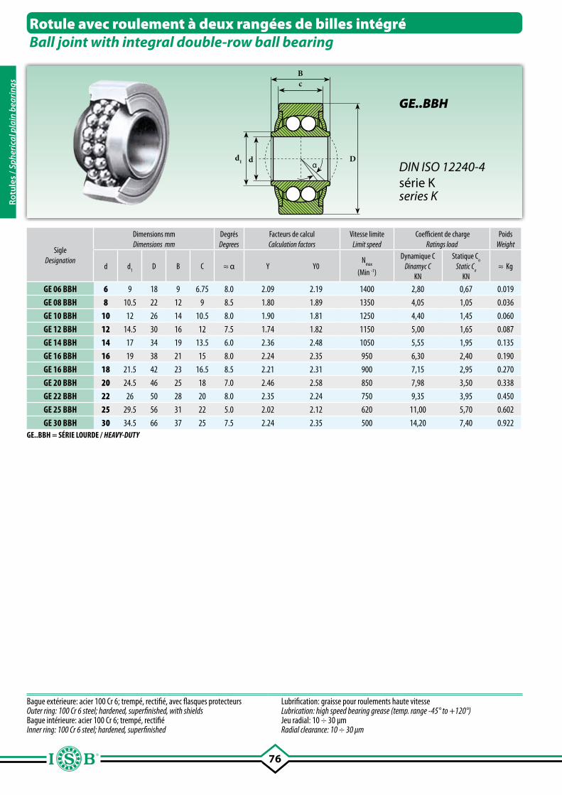
76
Bc
Ddα
d1
SigleDesignation
Dimensions mmDimensions mm
DegrésDegrees
Facteurs de calculCalculation factors
Vitesse limiteLimit speed
Coefficient de chargeRatings load
PoidsWeight
d d1
D B C ≈ α Y Y0N
max
(Min -1)
Dynamique CDinamyc C
KN
Statique Co
Static Co
KN≈ Kg
GE 06 BBH 6 9 18 9 6.75 8.0 2.09 2.19 1400 2,80 0,67 0.019
GE 08 BBH 8 10.5 22 12 9 8.5 1.80 1.89 1350 4,05 1,05 0.036
GE 10 BBH 10 12 26 14 10.5 8.0 1.90 1.81 1250 4,40 1,45 0.060
GE 12 BBH 12 14.5 30 16 12 7.5 1.74 1.82 1150 5,00 1,65 0.087
GE 14 BBH 14 17 34 19 13.5 6.0 2.36 2.48 1050 5,55 1,95 0.135
GE 16 BBH 16 19 38 21 15 8.0 2.24 2.35 950 6,30 2,40 0.190
GE 16 BBH 18 21.5 42 23 16.5 8.5 2.21 2.31 900 7,15 2,95 0.270
GE 20 BBH 20 24.5 46 25 18 7.0 2.46 2.58 850 7,98 3,50 0.338
GE 22 BBH 22 26 50 28 20 8.0 2.35 2.24 750 9,35 3,95 0.450
GE 25 BBH 25 29.5 56 31 22 5.0 2.02 2.12 620 11,00 5,70 0.602
GE 30 BBH 30 34.5 66 37 25 7.5 2.24 2.35 500 14,20 7,40 0.922
Bague extérieure: acier 100 Cr 6; trempé, rectifié, avec flasques protecteurs Outer ring: 100 Cr 6 steel; hardened, superfinished, with shieldsBague intérieure: acier 100 Cr 6; trempé, rectifié Inner ring: 100 Cr 6 steel; hardened, superfinished
Lubrification: graisse pour roulements haute vitesseLubrication: high speed bearing grease (temp. range -45° to +120°)Jeu radial: 10 ÷ 30 µmRadial clearance: 10 ÷ 30 µm
Rotule avec roulement à deux rangées de billes intégréBall joint with integral double-row ball bearing
GE..BBH
DIN ISO 12240-4série Kseries K
GE..BBH = SÉRIE LOURDE / HEAVY-DUTY
Rotu
les
/ Sph
eric
al p
lain
bea
ring
s
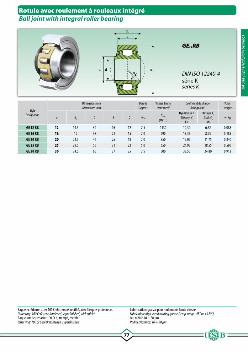
77
Bc
Ddα
d1
SigleDesignation
Dimensions mmDimensions mm
DegrésDegrees
Vitesse limiteLimit speed
Coefficient de chargeRatings load
PoidsWeight
d d1
D B C ≈ αN
max
(Min -1)
Dynamique CDinamyc C
KN
Statique Co
Static Co
KN≈ Kg
GE 12 RB 12 14.5 30 16 12 7.5 1130 10,30 6,62 0.088
GE 16 RB 16 19 38 21 15 7.0 990 13,35 8,95 0.185
GE 20 RB 20 24.5 46 25 18 7.0 850 17,05 11,75 0.340
GE 25 RB 25 29.5 56 31 22 5.0 650 24,95 18,55 0.596
GE 30 RB 30 34.5 66 37 25 7.5 500 32,55 24,80 0.912
Bague extérieure: acier 100 Cr 6; trempé, rectifié, avec flasques protecteurs Outer ring: 100 Cr 6 steel; hardened, superfinished, with shieldsBague intérieure: acier 100 Cr 6; trempé, rectifié Inner ring: 100 Cr 6 steel; hardened, superfinished
Lubrification: graisse pour roulements haute vitesseLubrication: high speed bearing grease (temp. range -45° to +120°)Jeu radial: 10 ÷ 30 µmRadial clearance: 10 ÷ 30 µm
Rotule avec roulement à rouleaux intégréBall joint with integral roller bearing
GE..RB
DIN ISO 12240-4série Kseries K Ro
tule
s / S
pher
ical
pla
in b
eari
ngs

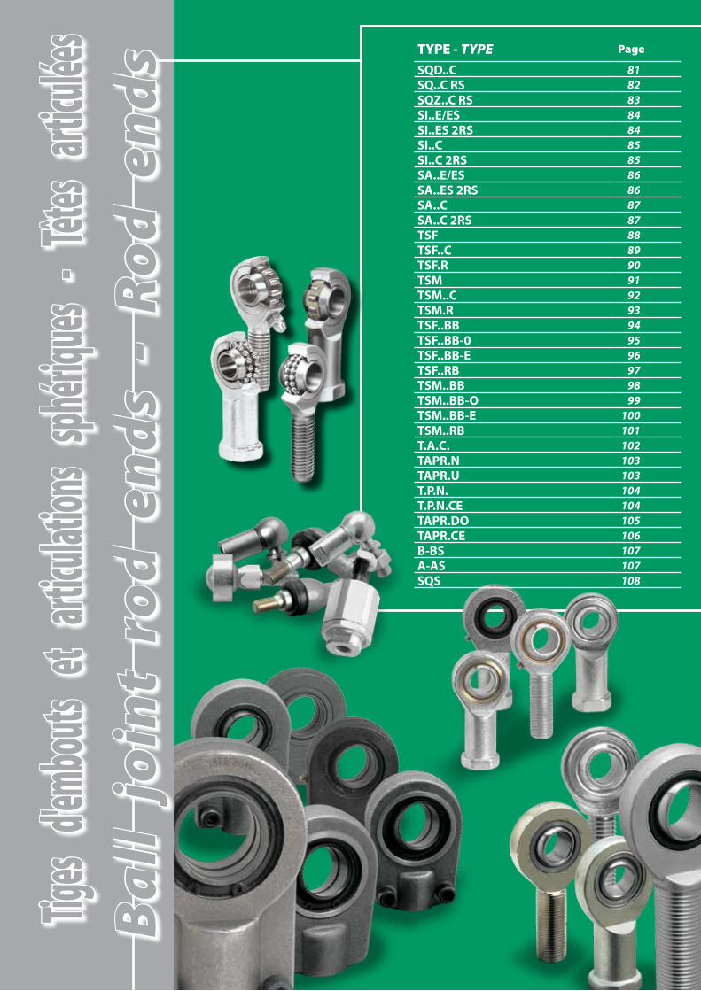
Tiges
d'emb
outs
et art
iculati
ons s
phériq
ues -
Têtes
articu
lées TYPE - TYPE Page
SQD..C 81SQ..C RS 82SQZ..C RS 83SI..E/ES 84SI..ES 2RS 84SI..C 85SI..C 2RS 85SA..E/ES 86SA..ES 2RS 86SA..C 87SA..C 2RS 87TSF 88TSF..C 89TSF.R 90TSM 91TSM..C 92TSM.R 93TSF..BB 94TSF..BB-0 95TSF..BB-E 96TSF..RB 97TSM..BB 98TSM..BB-O 99TSM..BB-E 100TSM..RB 101T.A.C. 102TAPR.N 103TAPR.U 103T.P.N. 104T.P.N.CE 104TAPR.DO 105TAPR.CE 106B-BS 107A-AS 107SQS 108
Ba
ll j
oin
t ro
d e
nd
s -
Ro
d e
nd
s

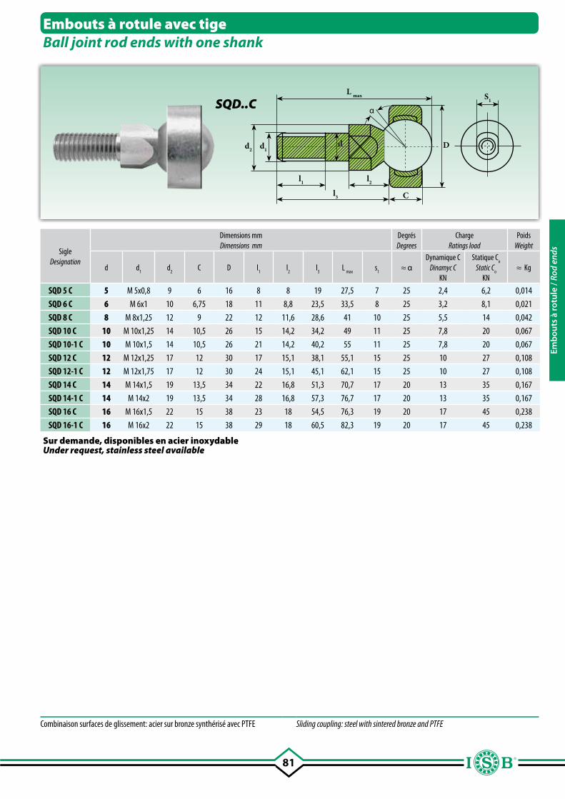
81
C
α
d1d2d
l1 l2
l3
D
S1L max
SigleDesignation
Dimensions mmDimensions mm
DegrésDegrees
ChargeRatings load
PoidsWeight
d d1
d2
C D l1
l2
l3
L max
s1
≈ αDynamique C
Dinamyc CKN
Statique Co
Static Co
KN≈ Kg
SQD 5 C 5 M 5x0,8 9 6 16 8 8 19 27,5 7 25 2,4 6,2 0,014
SQD 6 C 6 M 6x1 10 6,75 18 11 8,8 23,5 33,5 8 25 3,2 8,1 0,021
SQD 8 C 8 M 8x1,25 12 9 22 12 11,6 28,6 41 10 25 5,5 14 0,042
SQD 10 C 10 M 10x1,25 14 10,5 26 15 14,2 34,2 49 11 25 7,8 20 0,067
SQD 10-1 C 10 M 10x1,5 14 10,5 26 21 14,2 40,2 55 11 25 7,8 20 0,067
SQD 12 C 12 M 12x1,25 17 12 30 17 15,1 38,1 55,1 15 25 10 27 0,108
SQD 12-1 C 12 M 12x1,75 17 12 30 24 15,1 45,1 62,1 15 25 10 27 0,108
SQD 14 C 14 M 14x1,5 19 13,5 34 22 16,8 51,3 70,7 17 20 13 35 0,167
SQD 14-1 C 14 M 14x2 19 13,5 34 28 16,8 57,3 76,7 17 20 13 35 0,167
SQD 16 C 16 M 16x1,5 22 15 38 23 18 54,5 76,3 19 20 17 45 0,238
SQD 16-1 C 16 M 16x2 22 15 38 29 18 60,5 82,3 19 20 17 45 0,238
Embouts à rotule avec tigeBall joint rod ends with one shank
SQD..C
Combinaison surfaces de glissement: acier sur bronze synthérisé avec PTFE Sliding coupling: steel with sintered bronze and PTFE
Sur demande, disponibles en acier inoxydableUnder request, stainless steel available
Emb
outs
à ro
tule
/ Ro
d en
ds
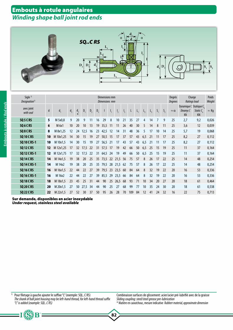
82
d3D3 S2S1
l2
d
L1
L
l
L3
L2
l1
d2
l3
d1D1D2
α α
Sigle 1)
Designation1)
Dimensions mmDimensions mm
DegrésDegrees
ChargeRatings load
PoidsWeight
avec joint with seal
d d1
d2 d
3
*D
1 D
2D
3 l l
1 l
2l
3 L L
1L
2 L
3 S
1S
2≈ α
Dynamique CDinamyc C
KN
Statique Co
Static Co
KN≈ Kg
SQ 5 C RS 5 M 5x0,8 9 20 9 11 16 29 8 10 21 35 27 4 14 7 9 25 2,7 9,2 0,026
SQ 6 C RS 6 M 6x1 10 20 10 13 19 35,5 11 11 26 40 30 5 14 8 11 25 3,6 12 0,039
SQ 8 C RS 8 M 8x1,25 12 24 12,5 16 23 42,5 12 14 31 48 36 5 17 10 14 25 5,7 19 0,068
SQ 10 C RS 10 M 10x1,25 14 30 15 19 27 50,5 15 17 37 57 43 6,5 21 11 17 25 8,2 27 0,112
SQ 10 C RS-1 10 M 10x1,5 14 30 15 19 27 56,5 21 17 43 57 43 6,5 21 11 17 25 8,2 27 0,112
SQ 12 C RS 12 M 12x1,25 17 32 17,5 22 31 57,5 17 19 42 66 50 6,5 25 15 19 25 11 37 0,164
SQ 12 C RS-1 12 M 12x1,75 17 32 17,5 22 31 64,5 24 19 49 66 50 6,5 25 15 19 25 11 37 0,164
SQ 14 C RS 14 M 14x1,5 19 38 20 25 35 73,5 22 21,5 56 75 57 8 26 17 22 25 14 48 0,254
SQ 14 C RS-1 14 M 14x2 19 38 20 25 35 79,5 28 21,5 62 75 57 8 26 17 22 25 14 48 0,254
SQ 16 C RS 16 M 16x1,5 22 44 22 27 39 79,5 23 23,5 60 84 64 8 32 19 22 20 16 53 0,336
SQ 16 C RS-1 16 M 16x2 22 44 22 27 39 85,5 29 23,5 66 84 64 8 32 19 22 20 16 53 0,336
SQ 18 C RS 18 M 18x1,5 23 45 25 31 44 90 25 26,5 68 93 71 10 34 20 27 20 18 61 0,464
SQ 20 C RS 20 M 20x1,5 27 50 27,5 34 44 90 25 27 68 99 77 10 35 24 30 20 18 61 0,538
SQ 22 C RS 22 M 22x1,5 27 52 30 37 50 95 26 28 70 109 84 12 41 24 32 16 22 75 0,713
Embouts à rotule angulairesWinding shape ball joint rod ends
SQ..C RS
1) Pour filetage à gauche ajouter le suffixe “L” (exemple: SQL..C RS) The shank of ball joint housing may be left-hand thread, for left-hand thread suffix
“L” is added (example: SQL..C RS)
Combinaison surfaces de glissement: acier/acier pré-lubrifié avec de la graisseSliding coupling: steel/steel grease pre-lubrication* Matière en caoutchouc, mesure indicative Rubberr material, approximate dimension
Sur demande, disponibles en acier inoxydableUnder request, stainless steel available
Emb
outs
à ro
tule
/ Ro
d en
ds
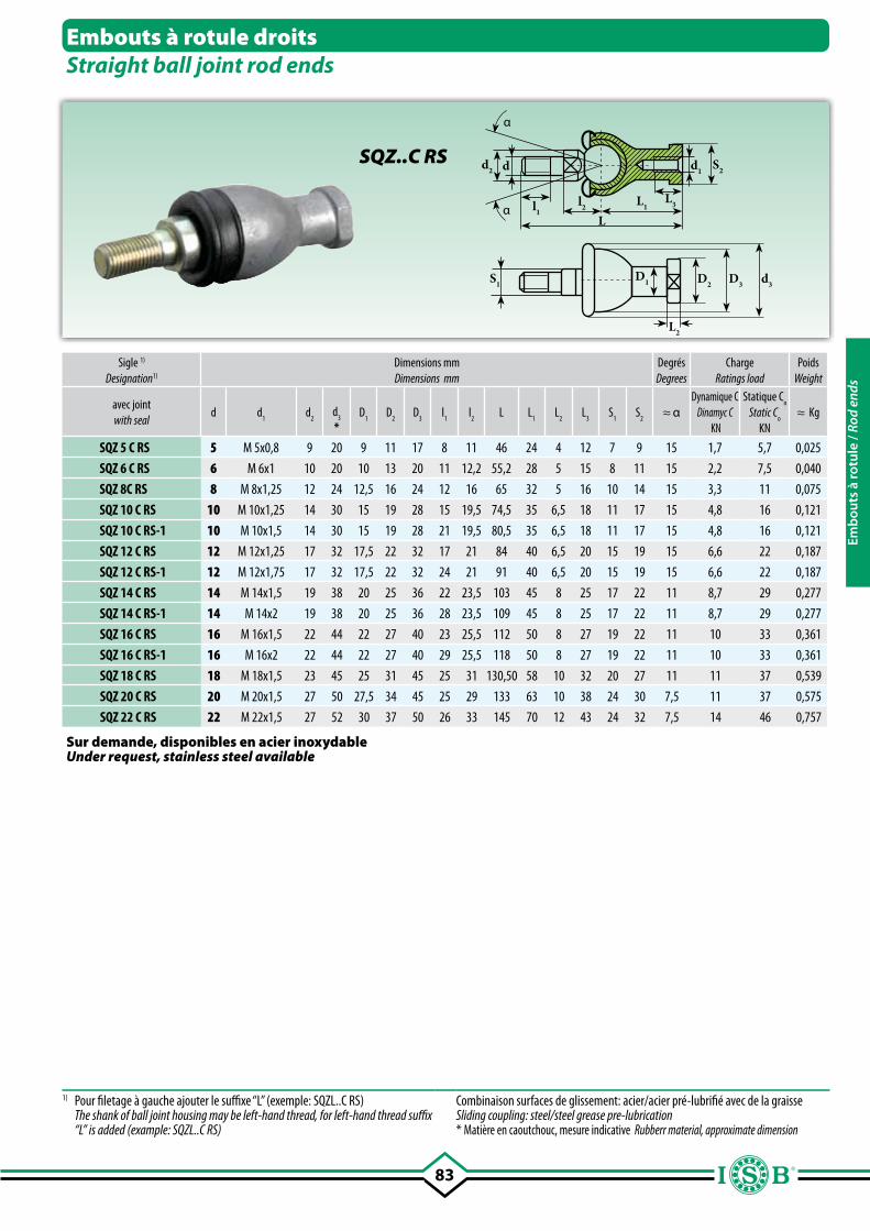
83
L2
D1S1 D2 D3 d3
L3l1
α
α
d d1d2 S2
Ll2 L1
Sigle 1)
Designation1)
Dimensions mmDimensions mm
DegrésDegrees
ChargeRatings load
PoidsWeight
avec jointwith seal
d d1
d2 d
3
*D
1 D
2 D
3 l
1 l
2L L
1L
2 L
3 S
1S
2≈ α
Dynamique CDinamyc C
KN
Statique Co
Static Co
KN≈ Kg
SQZ 5 C RS 5 M 5x0,8 9 20 9 11 17 8 11 46 24 4 12 7 9 15 1,7 5,7 0,025
SQZ 6 C RS 6 M 6x1 10 20 10 13 20 11 12,2 55,2 28 5 15 8 11 15 2,2 7,5 0,040
SQZ 8C RS 8 M 8x1,25 12 24 12,5 16 24 12 16 65 32 5 16 10 14 15 3,3 11 0,075
SQZ 10 C RS 10 M 10x1,25 14 30 15 19 28 15 19,5 74,5 35 6,5 18 11 17 15 4,8 16 0,121
SQZ 10 C RS-1 10 M 10x1,5 14 30 15 19 28 21 19,5 80,5 35 6,5 18 11 17 15 4,8 16 0,121
SQZ 12 C RS 12 M 12x1,25 17 32 17,5 22 32 17 21 84 40 6,5 20 15 19 15 6,6 22 0,187
SQZ 12 C RS-1 12 M 12x1,75 17 32 17,5 22 32 24 21 91 40 6,5 20 15 19 15 6,6 22 0,187
SQZ 14 C RS 14 M 14x1,5 19 38 20 25 36 22 23,5 103 45 8 25 17 22 11 8,7 29 0,277
SQZ 14 C RS-1 14 M 14x2 19 38 20 25 36 28 23,5 109 45 8 25 17 22 11 8,7 29 0,277
SQZ 16 C RS 16 M 16x1,5 22 44 22 27 40 23 25,5 112 50 8 27 19 22 11 10 33 0,361
SQZ 16 C RS-1 16 M 16x2 22 44 22 27 40 29 25,5 118 50 8 27 19 22 11 10 33 0,361
SQZ 18 C RS 18 M 18x1,5 23 45 25 31 45 25 31 130,50 58 10 32 20 27 11 11 37 0,539
SQZ 20 C RS 20 M 20x1,5 27 50 27,5 34 45 25 29 133 63 10 38 24 30 7,5 11 37 0,575
SQZ 22 C RS 22 M 22x1,5 27 52 30 37 50 26 33 145 70 12 43 24 32 7,5 14 46 0,757
Embouts à rotule droitsStraight ball joint rod ends
SQZ..C RS
1) Pour filetage à gauche ajouter le suffixe “L” (exemple: SQZL..C RS) The shank of ball joint housing may be left-hand thread, for left-hand thread suffix
“L” is added (example: SQZL..C RS)
Combinaison surfaces de glissement: acier/acier pré-lubrifié avec de la graisseSliding coupling: steel/steel grease pre-lubrication* Matière en caoutchouc, mesure indicative Rubberr material, approximate dimension
Sur demande, disponibles en acier inoxydableUnder request, stainless steel available
Emb
outs
à ro
tule
/ Ro
d en
ds
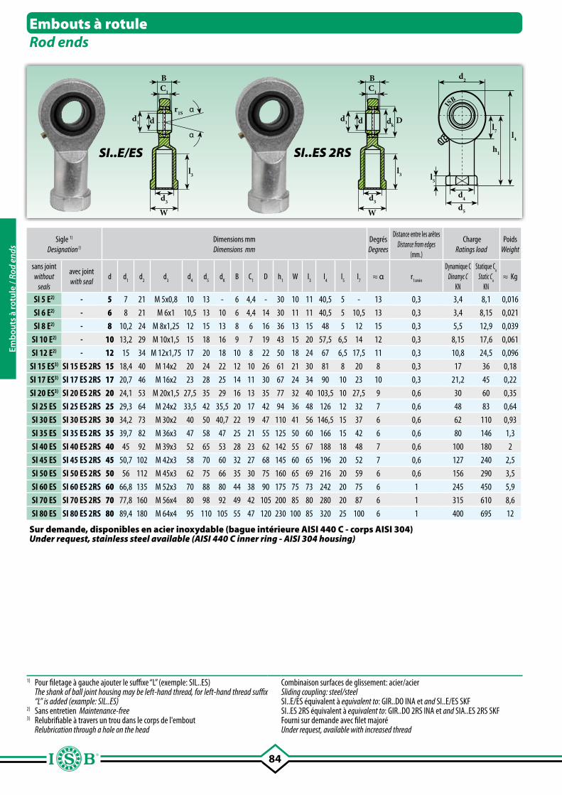
84
dd1
d3
W
α
α
BC1
l3
r1S
dd1
d3
W
BC1
l3
dkD
l5
d2
d4
d5
l7
h1
l4
ISB
Sigle 1)
Designation1)
Dimensions mmDimensions mm
DegrésDegrees
Distance entre les arêtesDistance from edges
(mm.)
ChargeRatings load
PoidsWeight
sans joint without
seals
avec jointwith seal
d d1 d
2 d
3d
4 d
5 d
K B C
1 D h
1W l
3 l
4 l
5 l
7≈ α r
1smin
Dynamique CDinamyc C
KN
Statique Co
Static Co
KN≈ Kg
SI 5 E2) - 5 7 21 M 5x0,8 10 13 - 6 4,4 - 30 10 11 40,5 5 - 13 0,3 3,4 8,1 0,016
SI 6 E2) - 6 8 21 M 6x1 10,5 13 10 6 4,4 14 30 11 11 40,5 5 10,5 13 0,3 3,4 8,15 0,021
SI 8 E2) - 8 10,2 24 M 8x1,25 12 15 13 8 6 16 36 13 15 48 5 12 15 0,3 5,5 12,9 0,039
SI 10 E2) - 10 13,2 29 M 10x1,5 15 18 16 9 7 19 43 15 20 57,5 6,5 14 12 0,3 8,15 17,6 0,061
SI 12 E2) - 12 15 34 M 12x1,75 17 20 18 10 8 22 50 18 24 67 6,5 17,5 11 0,3 10,8 24,5 0,096
SI 15 ES3) SI 15 ES 2RS 15 18,4 40 M 14x2 20 24 22 12 10 26 61 21 30 81 8 20 8 0,3 17 36 0,18
SI 17 ES3) SI 17 ES 2RS 17 20,7 46 M 16x2 23 28 25 14 11 30 67 24 34 90 10 23 10 0,3 21,2 45 0,22
SI 20 ES3) SI 20 ES 2RS 20 24,1 53 M 20x1,5 27,5 35 29 16 13 35 77 32 40 103,5 10 27,5 9 0,6 30 60 0,35
SI 25 ES SI 25 ES 2RS 25 29,3 64 M 24x2 33,5 42 35,5 20 17 42 94 36 48 126 12 32 7 0,6 48 83 0,64
SI 30 ES SI 30 ES 2RS 30 34,2 73 M 30x2 40 50 40,7 22 19 47 110 41 56 146,5 15 37 6 0,6 62 110 0,93
SI 35 ES SI 35 ES 2RS 35 39,7 82 M 36x3 47 58 47 25 21 55 125 50 60 166 15 42 6 0,6 80 146 1,3
SI 40 ES SI 40 ES 2RS 40 45 92 M 39x3 52 65 53 28 23 62 142 55 67 188 18 48 7 0,6 100 180 2
SI 45 ES SI 45 ES 2RS 45 50,7 102 M 42x3 58 70 60 32 27 68 145 60 65 196 20 52 7 0,6 127 240 2,5
SI 50 ES SI 50 ES 2RS 50 56 112 M 45x3 62 75 66 35 30 75 160 65 69 216 20 59 6 0,6 156 290 3,5
SI 60 ES SI 60 ES 2RS 60 66,8 135 M 52x3 70 88 80 44 38 90 175 75 73 242 20 75 6 1 245 450 5,9
SI 70 ES SI 70 ES 2RS 70 77,8 160 M 56x4 80 98 92 49 42 105 200 85 80 280 20 87 6 1 315 610 8,6
SI 80 ES SI 80 ES 2RS 80 89,4 180 M 64x4 95 110 105 55 47 120 230 100 85 320 25 100 6 1 400 695 12
Embouts à rotuleRod ends
SI..ES 2RSSI..E/ES
1) Pour filetage à gauche ajouter le suffixe “L” (exemple: SIL..ES) The shank of ball joint housing may be left-hand thread, for left-hand thread suffix
“L” is added (example: SIL..ES)2) Sans entretien Maintenance-free3) Relubrifiable à travers un trou dans le corps de l'embout Relubrication through a hole on the head
Combinaison surfaces de glissement: acier/acier Sliding coupling: steel/steel SI..E/ES équivalent à equivalent to: GIR..DO INA et and SI..E/ES SKFSI..ES 2RS équivalent à equivalent to: GIR..DO 2RS INA et and SIA..ES 2RS SKFFourni sur demande avec filet majoréUnder request, available with increased thread
Sur demande, disponibles en acier inoxydable (bague intérieure AISI 440 C - corps AISI 304)Under request, stainless steel available (AISI 440 C inner ring - AISI 304 housing)
Emb
outs
à ro
tule
/ Ro
d en
ds
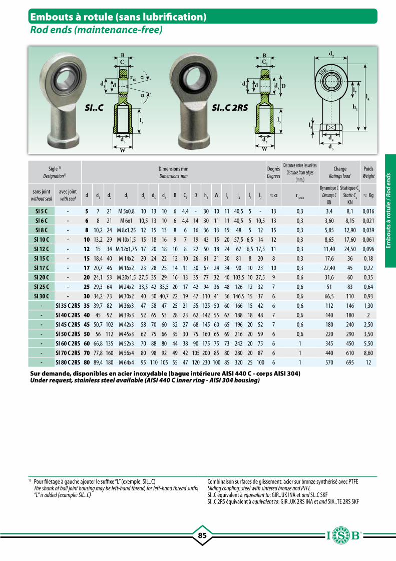
85
dd1
d3
W
α
α
BC1
l3
r1S
dd1
d3
W
BC1
l3
dk D
l5
d2
d4
d5
l7
h1
l4
ISB
Sigle 1)
Designation1)
Dimensions mmDimensions mm
DegrésDegrees
Distance entre les arêtesDistance from edges
(mm.)
ChargeRatings load
PoidsWeight
sans jointwithout seal
avec jointwith seal
d d1 d
2 d
3d
4 d
5 d
K B C
1 D h
1W l
3 l
4 l
5 l
7≈ α r
1smin
Dynamique CDinamyc C
KN
Statique Co
Static Co
KN≈ Kg
SI 5 C - 5 7 21 M 5x0,8 10 13 10 6 4,4 - 30 10 11 40,5 5 - 13 0,3 3,4 8,1 0,016
SI 6 C - 6 8 21 M 6x1 10,5 13 10 6 4,4 14 30 11 11 40,5 5 10,5 13 0,3 3,60 8,15 0,021
SI 8 C - 8 10,2 24 M 8x1,25 12 15 13 8 6 16 36 13 15 48 5 12 15 0,3 5,85 12,90 0,039
SI 10 C - 10 13,2 29 M 10x1,5 15 18 16 9 7 19 43 15 20 57,5 6,5 14 12 0,3 8,65 17,60 0,061
SI 12 C - 12 15 34 M 12x1,75 17 20 18 10 8 22 50 18 24 67 6,5 17,5 11 0,3 11,40 24,50 0,096
SI 15 C - 15 18,4 40 M 14x2 20 24 22 12 10 26 61 21 30 81 8 20 8 0,3 17,6 36 0,18
SI 17 C - 17 20,7 46 M 16x2 23 28 25 14 11 30 67 24 34 90 10 23 10 0,3 22,40 45 0,22
SI 20 C - 20 24,1 53 M 20x1,5 27,5 35 29 16 13 35 77 32 40 103,5 10 27,5 9 0,6 31,6 60 0,35
SI 25 C - 25 29,3 64 M 24x2 33,5 42 35,5 20 17 42 94 36 48 126 12 32 7 0,6 51 83 0,64
SI 30 C - 30 34,2 73 M 30x2 40 50 40,7 22 19 47 110 41 56 146,5 15 37 6 0,6 66,5 110 0,93
- SI 35 C 2RS 35 39,7 82 M 36x3 47 58 47 25 21 55 125 50 60 166 15 42 6 0,6 112 146 1,30
- SI 40 C 2RS 40 45 92 M 39x3 52 65 53 28 23 62 142 55 67 188 18 48 7 0,6 140 180 2
- SI 45 C 2RS 45 50,7 102 M 42x3 58 70 60 32 27 68 145 60 65 196 20 52 7 0,6 180 240 2,50
- SI 50 C 2RS 50 56 112 M 45x3 62 75 66 35 30 75 160 65 69 216 20 59 6 0,6 220 290 3,50
- SI 60 C 2RS 60 66,8 135 M 52x3 70 88 80 44 38 90 175 75 73 242 20 75 6 1 345 450 5,50
- SI 70 C 2RS 70 77,8 160 M 56x4 80 98 92 49 42 105 200 85 80 280 20 87 6 1 440 610 8,60
- SI 80 C 2RS 80 89,4 180 M 64x4 95 110 105 55 47 120 230 100 85 320 25 100 6 1 570 695 12
Embouts à rotule (sans lubrification)Rod ends (maintenance-free)
SI..C SI..C 2RS
1) Pour filetage à gauche ajouter le suffixe “L” (exemple: SIL..C) The shank of ball joint housing may be left-hand thread, for left-hand thread suffix
“L” is added (example: SIL..C)
Combinaison surfaces de glissement: acier sur bronze synthérisé avec PTFESliding coupling: steel with sintered bronze and PTFE SI..C équivalent à equivalent to: GIR..UK INA et and SI..C SKFSI..C 2RS équivalent à equivalent to: GIR..UK 2RS INA et and SIA..TE 2RS SKF
Sur demande, disponibles en acier inoxydable (bague intérieure AISI 440 C - corps AISI 304)Under request, stainless steel available (AISI 440 C inner ring - AISI 304 housing)
Emb
outs
à ro
tule
/ Ro
d en
ds
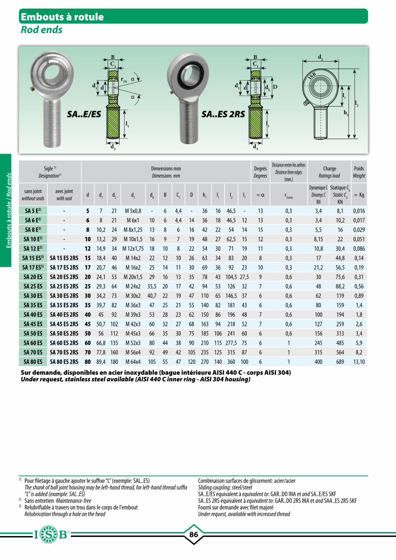
86
dd1
d3
α
α
BC1
l1
r1S
dk Ddd1
d3
BC1
l1
d2
l7
h1
l2
ISB
Embouts à rotuleRod ends
SA..E/ES
Sigle 1)
Designation1)
Dimensions mmDimensions mm
DegrésDegrees
Distance entre les arêtesDistance from edges
(mm.)
ChargeRatings load
PoidsWeight
sans joint without seals
avec jointwith seal
d d1 d
2 d
3d
K B C
1 D h
1l
1 l
2 l
7≈ α r
1smin
Dynamique CDinamyc C
KN
Statique Co
Static Co
KN≈ Kg
SA 5 E2) - 5 7 21 M 5x0,8 - 6 4,4 - 36 16 46,5 - 13 0,3 3,4 8,1 0,016
SA 6 E2) - 6 8 21 M 6x1 10 6 4,4 14 36 18 46,5 12 13 0,3 3,4 10,2 0,017
SA 8 E2) - 8 10,2 24 M 8x1,25 13 8 6 16 42 22 54 14 15 0,3 5,5 16 0,029
SA 10 E2) - 10 13,2 29 M 10x1,5 16 9 7 19 48 27 62,5 15 12 0,3 8,15 22 0,051
SA 12 E2) - 12 14,9 34 M 12x1,75 18 10 8 22 54 30 71 19 11 0,3 10,8 30,4 0,086
SA 15 ES3) SA 15 ES 2RS 15 18,4 40 M 14x2 22 12 10 26 63 34 83 20 8 0,3 17 44,8 0,14
SA 17 ES3) SA 17 ES 2RS 17 20,7 46 M 16x2 25 14 11 30 69 36 92 23 10 0,3 21,2 56,5 0,19
SA 20 ES SA 20 ES 2RS 20 24,1 53 M 20x1,5 29 16 13 35 78 43 104,5 27,5 9 0,6 30 75,6 0,31
SA 25 ES SA 25 ES 2RS 25 29,3 64 M 24x2 35,5 20 17 42 94 53 126 32 7 0,6 48 88,2 0,56
SA 30 ES SA 30 ES 2RS 30 34,2 73 M 30x2 40,7 22 19 47 110 65 146,5 37 6 0,6 62 119 0,89
SA 35 ES SA 35 ES 2RS 35 39,7 82 M 36x3 47 25 21 55 140 82 181 43 6 0,6 80 159 1,4
SA 40 ES SA 40 ES 2RS 40 45 92 M 39x3 53 28 23 62 150 86 196 48 7 0,6 100 194 1,8
SA 45 ES SA 45 ES 2RS 45 50,7 102 M 42x3 60 32 27 68 163 94 218 52 7 0,6 127 259 2,6
SA 50 ES SA 50 ES 2RS 50 56 112 M 45x3 66 35 30 75 185 106 241 60 6 0,6 156 313 3,4
SA 60 ES SA 60 ES 2RS 60 66,8 135 M 52x3 80 44 38 90 210 115 277,5 75 6 1 245 485 5,9
SA 70 ES SA 70 ES 2RS 70 77,8 160 M 56x4 92 49 42 105 235 125 315 87 6 1 315 564 8,2
SA 80 ES SA 80 ES 2RS 80 89,4 180 M 64x4 105 55 47 120 270 140 360 100 6 1 400 689 13,10
SA..ES 2RS
1) Pour filetage à gauche ajouter le suffixe “L” (exemple: SAL..ES) The shank of ball joint housing may be left-hand thread, for left-hand thread suffix
“L” is added (example: SAL..ES)2) Sans entretien Maintenance-free3) Relubrifiable à travers un trou dans le corps de l'embout Relubrication through a hole on the head
Combinaison surfaces de glissement: acier/acier Sliding coupling: steel/steel SA..E/ES équivalent à equivalent to: GAR..DO INA et and SA..E/ES SKFSA..ES 2RS équivalent à equivalent to: GAR..DO 2RS INA et and SAA..ES 2RS SKFFourni sur demande avec filet majoréUnder request, available with increased thread
Sur demande, disponibles en acier inoxydable (bague intérieure AISI 440 C - corps AISI 304)Under request, stainless steel available (AISI 440 C inner ring - AISI 304 housing)
Emb
outs
à ro
tule
/ Ro
d en
ds
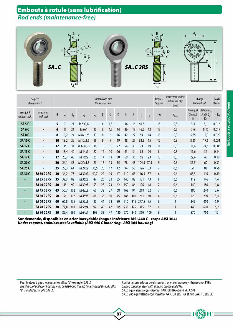
87
d2
l7
h1
l2
dk Ddd1
d3
BC1
l1
dd1
d3
α
α
BC1
l1
r1S
ISB
Sigle 1)
Designation1)
Dimensions mmDimensions mm
DegrésDegrees
Distance entre les arêtesDistance from edges
(mm.)
ChargeRatings load
PoidsWeight
sans joint without seals
avec jointwith seal
d d1 d
2 d
3d
K B C
1 D h
1 l
1 l
2 l
7≈ α r
1smin
Dynamique CDinamyc C
KN
Statique Co
Static Co
KN≈ Kg
SA 5 C - 5 7 21 M 5x0,8 - 6 4,3 - 36 16 46,5 - 13 0,3 3,4 8,1 0,016
SA 6 C - 6 8 21 M 6x1 10 6 4,3 14 36 18 46,5 12 13 0,3 3,6 8,15 0,017
SA 8 C - 8 10,2 24 M 8x1,25 13 8 6 16 42 22 54 14 15 0,3 5,85 12,9 0,029
SA 10 C - 10 13,2 29 M 10x1,5 16 9 7 19 48 27 62,5 15 12 0,3 8,65 17,6 0,051
SA 12 C - 12 15 34 M 12x1,75 18 10 8 22 54 30 71 19 11 0,3 11,4 24,5 0,086
SA 15 C - 15 18,4 40 M 14x2 22 12 10 26 63 34 83 20 8 0,3 17,6 36 0,14
SA 17 C - 17 20,7 46 M 16x2 25 14 11 30 69 36 92 23 10 0,3 22,4 45 0,19
SA 20 C - 20 24,1 53 M 20x1,5 29 16 13 35 78 43 104,5 27,5 9 0,6 31,5 60 0,31
SA 25 C - 25 29,3 64 M 24x2 35,5 20 17 42 94 53 126 33 7 0,6 51 83 0,56
SA 30 C SA 30 C 2RS 30 34,2 73 M 30x2 40,7 22 19 47 110 65 146,5 37 6 0,6 65,5 110 0,89
- SA 35 C 2RS 35 39,7 82 M 36x3 47 25 21 55 140 82 181 43 6 0,6 112 146 1,4
- SA 40 C 2RS 40 45 92 M 39x3 53 28 23 62 150 86 196 48 7 0,6 140 180 1,8
- SA 45 C 2RS 45 50,7 102 M 42x3 60 32 27 68 163 94 218 52 7 0,6 180 240 2,6
- SA 50 C 2RS 50 56 112 M 45x3 66 35 30 75 185 106 241 60 6 0,6 220 290 3,4
- SA 60 C 2RS 60 66,8 135 M 52x3 80 44 38 90 210 115 277,5 75 6 1 345 450 5,9
- SA 70 C 2RS 70 77,8 160 M 56x4 92 49 42 105 235 125 315 87 6 1 440 610 8,2
- SA 80 C 2RS 80 89,4 180 M 64x4 105 55 47 120 270 140 360 100 6 1 570 750 12
Embouts à rotule (sans lubrification)Rod ends (maintenance-free)
SA..C SA..C 2RS
1) Pour filetage à gauche ajouter le suffixe “L” (exemple: SAL..C) The shank of ball joint housing may be left-hand thread, for left-hand thread suffix
“L” is added (example: SAL..C)
Combinaison surfaces de glissement: acier sur bronze synthérisé avec PTFESliding coupling: steel with sintered bronze and PTFE SA..C équivalent à equivalent to: GAR..UK INA et and SA..C SKFSA..C 2RS équivalent à equivalent to: GAR..UK 2RS INA et and SAA..TE 2RS SKF
Sur demande, disponibles en acier inoxydable (bague intérieure AISI 440 C - corps AISI 304)Under request, stainless steel available (AISI 440 C inner ring - AISI 304 housing)
Emb
outs
à ro
tule
/ Ro
d en
ds
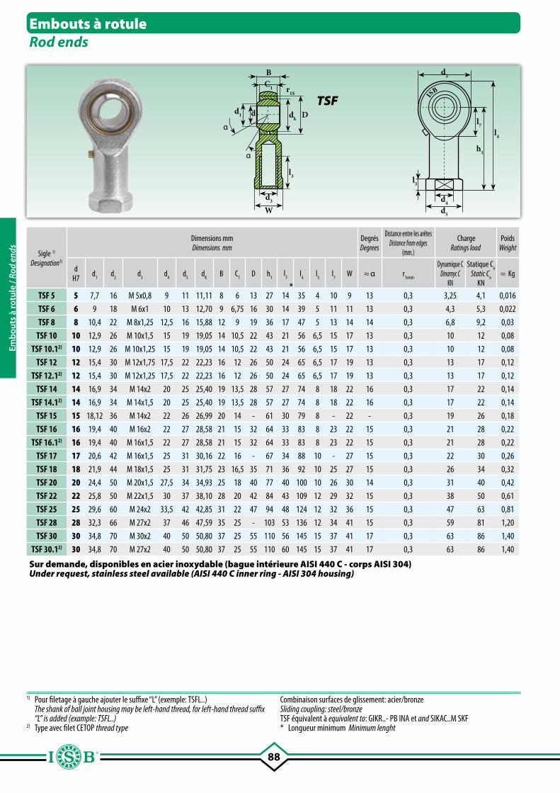
88
W
dd1
d3
BC1
l3
r1S
dk Dα
α
l5
d4
d2
l7
h1
l4
d5
ISB
Embouts à rotuleRod ends
TSF
Sigle 1)
Designation1)
Dimensions mmDimensions mm
DegrésDegrees
Distance entre les arêtesDistance from edges
(mm.)
ChargeRatings load
PoidsWeight
dH7 d
1d
2d
3d
4d
5d
KB C
1D h
1l
3
*
l4
l5
l7
W ≈ α r1smin
Dynamique CDinamyc C
KN
Statique Co
Static Co
KN≈ Kg
TSF 5 5 7,7 16 M 5x0,8 9 11 11,11 8 6 13 27 14 35 4 10 9 13 0,3 3,25 4,1 0,016
TSF 6 6 9 18 M 6x1 10 13 12,70 9 6,75 16 30 14 39 5 11 11 13 0,3 4,3 5,3 0,022
TSF 8 8 10,4 22 M 8x1,25 12,5 16 15,88 12 9 19 36 17 47 5 13 14 14 0,3 6,8 9,2 0,03
TSF 10 10 12,9 26 M 10x1,5 15 19 19,05 14 10,5 22 43 21 56 6,5 15 17 13 0,3 10 12 0,08
TSF 10.12) 10 12,9 26 M 10x1,25 15 19 19,05 14 10,5 22 43 21 56 6,5 15 17 13 0,3 10 12 0,08
TSF 12 12 15,4 30 M 12x1,75 17,5 22 22,23 16 12 26 50 24 65 6,5 17 19 13 0,3 13 17 0,12
TSF 12.12) 12 15,4 30 M 12x1,25 17,5 22 22,23 16 12 26 50 24 65 6,5 17 19 13 0,3 13 17 0,12
TSF 14 14 16,9 34 M 14x2 20 25 25,40 19 13,5 28 57 27 74 8 18 22 16 0,3 17 22 0,14
TSF 14.12) 14 16,9 34 M 14x1,5 20 25 25,40 19 13,5 28 57 27 74 8 18 22 16 0,3 17 22 0,14
TSF 15 15 18,12 36 M 14x2 22 26 26,99 20 14 - 61 30 79 8 - 22 - 0,3 19 26 0,18
TSF 16 16 19,4 40 M 16x2 22 27 28,58 21 15 32 64 33 83 8 23 22 15 0,3 21 28 0,22
TSF 16.12) 16 19,4 40 M 16x1,5 22 27 28,58 21 15 32 64 33 83 8 23 22 15 0,3 21 28 0,22
TSF 17 17 20,6 42 M 16x1,5 25 31 30,16 22 16 - 67 34 88 10 - 27 15 0,3 22 30 0,26
TSF 18 18 21,9 44 M 18x1,5 25 31 31,75 23 16,5 35 71 36 92 10 25 27 15 0,3 26 34 0,32
TSF 20 20 24,4 50 M 20x1,5 27,5 34 34,93 25 18 40 77 40 100 10 26 30 14 0,3 31 40 0,42
TSF 22 22 25,8 50 M 22x1,5 30 37 38,10 28 20 42 84 43 109 12 29 32 15 0,3 38 50 0,61
TSF 25 25 29,6 60 M 24x2 33,5 42 42,85 31 22 47 94 48 124 12 32 36 15 0,3 47 63 0,81
TSF 28 28 32,3 66 M 27x2 37 46 47,59 35 25 - 103 53 136 12 34 41 15 0,3 59 81 1,20
TSF 30 30 34,8 70 M 30x2 40 50 50,80 37 25 55 110 56 145 15 37 41 17 0,3 63 86 1,40
TSF 30.12) 30 34,8 70 M 27x2 40 50 50,80 37 25 55 110 60 145 15 37 41 17 0,3 63 86 1,40
1) Pour filetage à gauche ajouter le suffixe “L” (exemple: TSFL..) The shank of ball joint housing may be left-hand thread, for left-hand thread suffix “L” is added (example: TSFL..)
2) Type avec filet CETOP thread type
Combinaison surfaces de glissement: acier/bronzeSliding coupling: steel/bronzeTSF équivalent à equivalent to: GIKR..- PB INA et and SIKAC..M SKF* Longueur minimum Minimum lenght
Sur demande, disponibles en acier inoxydable (bague intérieure AISI 440 C - corps AISI 304)Under request, stainless steel available (AISI 440 C inner ring - AISI 304 housing)
Emb
outs
à ro
tule
/ Ro
d en
ds
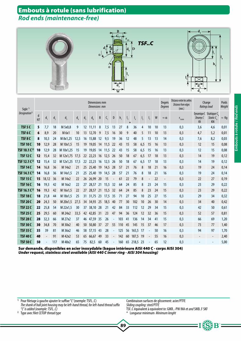
89
W
dd1
d3
BC1
l3
r1S
dkD
α
α
l5
d4
d2
l7
h1
l4
d5
ISB
Sigle 1)
Designation1)
Dimensions mmDimensions mm
DegrésDegrees
Distance entre les arêtesDistance from edges
(mm.)
ChargeRatings load
PoidsWeight
dH7 d
1d
2d
3d
4d
5d
KB C
1D h
1l
3
*
l4
l5
l7
W ≈ α r1smin
Dynamique CDinamyc C
KN
Statique Co
Static Co
KN≈ Kg
TSF 5 C 5 7,7 18 M 5x0,8 9 12 11,11 8 7,5 13 27 8 36 4 10 10 13 0,3 3,6 4,6 0,01
TSF 6 C 6 8,9 20 M 6x1 10 13 12,70 9 7,5 16 30 9 40 5 11 10 13 0,3 4,7 5,2 0,01
TSF 8 C 8 10,3 24 M 8x1,25 12,5 16 15,88 12 9,5 19 36 12 48 5 13 13 14 0,3 7,6 8,2 0,03
TSF 10 C 10 12,9 28 M 10x1,5 15 19 19,05 14 11,5 22 43 15 58 6,5 15 16 13 0,3 12 15 0,08
TSF 10.1 C 2) 10 12,9 28 M 10x1,25 15 19 19,05 14 11,5 22 43 15 58 6,5 15 16 13 0,3 12 15 0,08
TSF 12 C 12 15,4 32 M 12x1,75 17,5 22 22,23 16 12,5 26 50 18 67 6,5 17 18 13 0,3 14 19 0,12
TSF 12.1 C 2) 12 15,4 32 M 12x1,25 17,5 22 22,23 16 12,5 26 50 18 67 6,5 17 18 13 0,3 14 19 0,12
TSF 14 C 14 16,8 36 M 14x2 21 25 25,40 19 14,5 28 57 21 76 8 18 21 16 0,3 19 24 0,14
TSF 14.1 C 2) 14 16,8 36 M 14x1,5 21 25 25,40 19 14,5 28 57 21 76 8 18 21 16 0,3 19 24 0,14
TSF 15 C 15 18,12 36 M 14x2 22 26 26,99 20 15 - 61 22 79 8 - 22 - 0,3 22 27 0,19
TSF 16 C 16 19,3 42 M 16x2 22 27 28,57 21 15,5 32 64 24 85 8 23 24 15 0,3 23 29 0,22
TSF 16.1 C 2) 16 19,3 42 M 16x1,5 22 27 28,57 21 15,5 32 64 24 85 8 23 24 15 0,3 23 29 0,22
TSF 18 C 18 21,8 44 M 18x1,5 25 31 31,75 23 17,5 35 71 27 94 10 25 27 15 0,3 29 34 0,32
TSF 20 C 20 24,3 50 M 20x1,5 27,5 34 34,93 25 18,5 40 77 30 102 10 26 30 14 0,3 34 40 0,42
TSF 22 C 22 25,8 54 M 22x1,5 30 37 38,10 28 21 42 84 33 112 12 29 34 15 0,3 42 50 0,61
TSF 25 C 25 29,5 60 M 24x2 33,5 42 42,85 31 23 47 94 36 124 12 32 36 15 0,3 52 57 0,81
TSF 28 C 28 32,3 66 M 27x2 37 46 47,59 35 26 - 103 41 136 14 34 41 15 0,3 66 69 1,20
TSF 30 C 30 34,8 70 M 30x2 40 50 50,80 37 27 55 110 45 145 15 37 46 17 0,3 73 77 1,40
TSF 35 C 35 39 81 M 36x2 46 58 57,15 43 28 - 125 56 165,5 17 - 50 16 0,3 94 97 1,70
TSF 40 C 40 - 91 M 42x2 53 65 66,67 49 33 - 142 60 187,5 19 - 55 16 0,3 - - 2,40
TSF 50 C 50 - 117 M 48x2 65 75 82,5 60 45 - 160 65 218,5 23 - 65 12 0,3 - - 5,00
Embouts à rotule (sans lubrification)Rod ends (maintenance-free)
TSF..C
1) Pour filetage à gauche ajouter le suffixe “L” (exemple: TSFL..C) The shank of ball joint housing may be left-hand thread, for left-hand thread suffix
“L” is added (example: TSFL..C)2) Type avec filet CETOP thread type
Combinaison surfaces de glissement: acier/PTFESliding coupling: steel/PTFETSF..C équivalent à equivalent to: GIKR..-PW INA et and SIKB..F SKF* Longueur minimum Minimum lenght
Sur demande, disponibles en acier inoxydable (bague intérieure AISI 440 C - corps AISI 304)Under request, stainless steel available (AISI 440 C inner ring - AISI 304 housing)
Emb
outs
à ro
tule
/ Ro
d en
ds
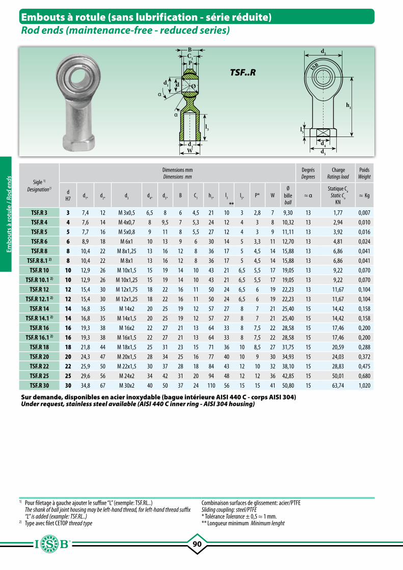
90
l5
d4
d2
h1
d5
P
α
α
dd1
BC1
Wd3
l3
Ø
ISB
Sigle 1)
Designation1)
Dimensions mmDimensions mm
DegrésDegrees
ChargeRatings load
PoidsWeight
dH7 d
1*d
2*d
3d
4*d
5*B C
1h
1*l
3
**
l5*
P* WØ
billeball
≈ αStatique C
oStatic C
oKN
≈ Kg
TSF.R 3 3 7,4 12 M 3x0,5 6,5 8 6 4,5 21 10 3 2,8 7 9,30 13 1,77 0,007
TSF.R 4 4 7,6 14 M 4x0,7 8 9,5 7 5,3 24 12 4 3 8 10,32 13 2,94 0,010
TSF.R 5 5 7,7 16 M 5x0,8 9 11 8 5,5 27 12 4 3 9 11,11 13 3,92 0,016
TSF.R 6 6 8,9 18 M 6x1 10 13 9 6 30 14 5 3,3 11 12,70 13 4,81 0,024
TSF.R 8 8 10,4 22 M 8x1,25 13 16 12 8 36 17 5 4,5 14 15,88 13 6,86 0,041
TSF.R 8.1 2) 8 10,4 22 M 8x1 13 16 12 8 36 17 5 4,5 14 15,88 13 6,86 0,041
TSF.R 10 10 12,9 26 M 10x1,5 15 19 14 10 43 21 6,5 5,5 17 19,05 13 9,22 0,070
TSF.R 10.1 2) 10 12,9 26 M 10x1,25 15 19 14 10 43 21 6,5 5,5 17 19,05 13 9,22 0,070
TSF.R 12 12 15,4 30 M 12x1,75 18 22 16 11 50 24 6,5 6 19 22,23 13 11,67 0,104
TSF.R 12.1 2) 12 15,4 30 M 12x1,25 18 22 16 11 50 24 6,5 6 19 22,23 13 11,67 0,104
TSF.R 14 14 16,8 35 M 14x2 20 25 19 12 57 27 8 7 21 25,40 15 14,42 0,158
TSF.R 14.1 2) 14 16,8 35 M 14x1,5 20 25 19 12 57 27 8 7 21 25,40 15 14,42 0,158
TSF.R 16 16 19,3 38 M 16x2 22 27 21 13 64 33 8 7,5 22 28,58 15 17,46 0,200
TSF.R 16.1 2) 16 19,3 38 M 16x1,5 22 27 21 13 64 33 8 7,5 22 28,58 15 17,46 0,200
TSF.R 18 18 21,8 44 M 18x1,5 25 31 23 15 71 36 10 8,5 27 31,75 15 20,59 0,288
TSF.R 20 20 24,3 47 M 20x1,5 28 34 25 16 77 40 10 9 30 34,93 15 24,03 0,372
TSF.R 22 22 25,9 50 M 22x1,5 30 37 28 18 84 43 12 10 32 38,10 15 28,83 0,475
TSF.R 25 25 29,6 56 M 24x2 34 42 31 20 94 48 12 12 36 42,85 15 50,01 0,680
TSF.R 30 30 34,8 67 M 30x2 40 50 37 24 110 56 15 15 41 50,80 15 63,74 1,020
Embouts à rotule (sans lubrification - série réduite)Rod ends (maintenance-free - reduced series)
TSF..R
1) Pour filetage à gauche ajouter le suffixe “L” (exemple: TSF.RL..) The shank of ball joint housing may be left-hand thread, for left-hand thread suffix
“L” is added (example: TSF.RL..)2) Type avec filet CETOP thread type
Combinaison surfaces de glissement: acier/PTFESliding coupling: steel/PTFE* Tolérance Tolerance ± 0,5 ≈ 1 mm.** Longueur minimum Minimum lenght
Sur demande, disponibles en acier inoxydable (bague intérieure AISI 440 C - corps AISI 304)Under request, stainless steel available (AISI 440 C inner ring - AISI 304 housing)
Emb
outs
à ro
tule
/ Ro
d en
ds
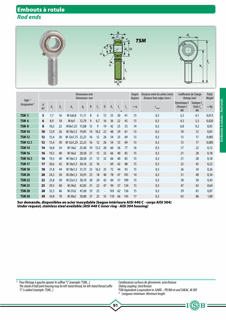
91
d2
h1
l4
dd1
d3
BC1
l3
r1S
dk Dα
α
ISB
Embouts à rotuleRod ends
TSM
Sigle 1)
Designation1)
Dimensions mmDimensions mm
DegrésDegrees
Distance entre les arêtes (mm)Distance from edges (mm.)
Coefficients de ChargeRatings load
PoidsWeight
dH7 d
1d
2d
3d
KB C
1D h
1l
3
*
l4
≈ α r1smin
Dynamique CDinamyc C
KN
Statique Co
Static Co
KN≈ Kg
TSM 5 5 7,7 16 M 5x0,8 11,11 8 6 13 33 20 41 13 0,3 3,3 4,1 0,013
TSM 6 6 8,9 18 M 6x1 12,70 9 6,7 16 36 22 45 13 0,3 4,3 5,3 0,020
TSM 8 8 10,3 22 M 8x1,25 15,88 12 9 19 42 25 53 14 0,3 6,8 9,2 0,03
TSM 10 10 12,9 26 M 10x1,5 19,05 14 10,5 22 48 29 61 13 0,3 10 12 0,05
TSM 12 12 15,4 30 M 12x1,75 22,23 16 12 26 54 33 69 13 0,3 13 17 0,085
TSM 12.1 12 15,4 30 M 12x1,25 22,23 16 12 26 54 33 69 13 0,3 13 17 0,085
TSM 14 14 16,8 34 M 14x2 25,40 19 13,5 28 60 36 77 16 0,3 17 22 0,12
TSM 16 16 19,3 40 M 16x2 28,58 21 15 32 66 40 85 15 0,3 21 28 0,18
TSM 16.1 16 19,3 40 M 16x1,5 28,58 21 15 32 66 40 85 15 0,3 21 28 0,18
TSM 17 17 20,6 42 M 16x1,5 30,16 22 16 - 69 42 88 15 0,3 22 45 0,23
TSM 18 18 21,8 44 M 18x1,5 31,75 23 16,5 35 72 44 93 15 0,3 26 34 0,26
TSM 20 20 24,3 50 M 20x1,5 34,93 25 18 40 78 47 101 14 0,3 31 40 0,34
TSM 22 22 25,8 50 M 22x1,5 38,10 28 20 42 84 51 109 15 0,3 38 50 0,43
TSM 25 25 29,5 60 M 24x2 42,85 31 22 47 94 57 124 15 0,3 47 63 0,64
TSM 28 28 32,3 66 M 27x2 47,60 35 25 - 103 62 136 15 0,3 59 81 0,87
TSM 30 30 34,8 70 M 30x2 50,80 37 25 55 110 66 145 17 0,3 63 86 1,00
1) Pour filetage à gauche ajouter le suffixe “L” (exemple: TSML..) The shank of ball joint housing may be left-hand thread, for left-hand thread suffix
“L” is added (example: TSML..)
Combinaison surfaces de glissement: acier/bronzeSliding coupling: steel/bronzeTSM équivalent à equivalent to: GAKR..- PB INA et and SAKAC..M SKF* Longueur minimum Minimum lenght
Sur demande, disponibles en acier inoxydable (bague intérieure AISI 440 C - corps AISI 304)Under request, stainless steel available (AISI 440 C inner ring - AISI 304 housing)
Emb
outs
à ro
tule
/ Ro
d en
ds
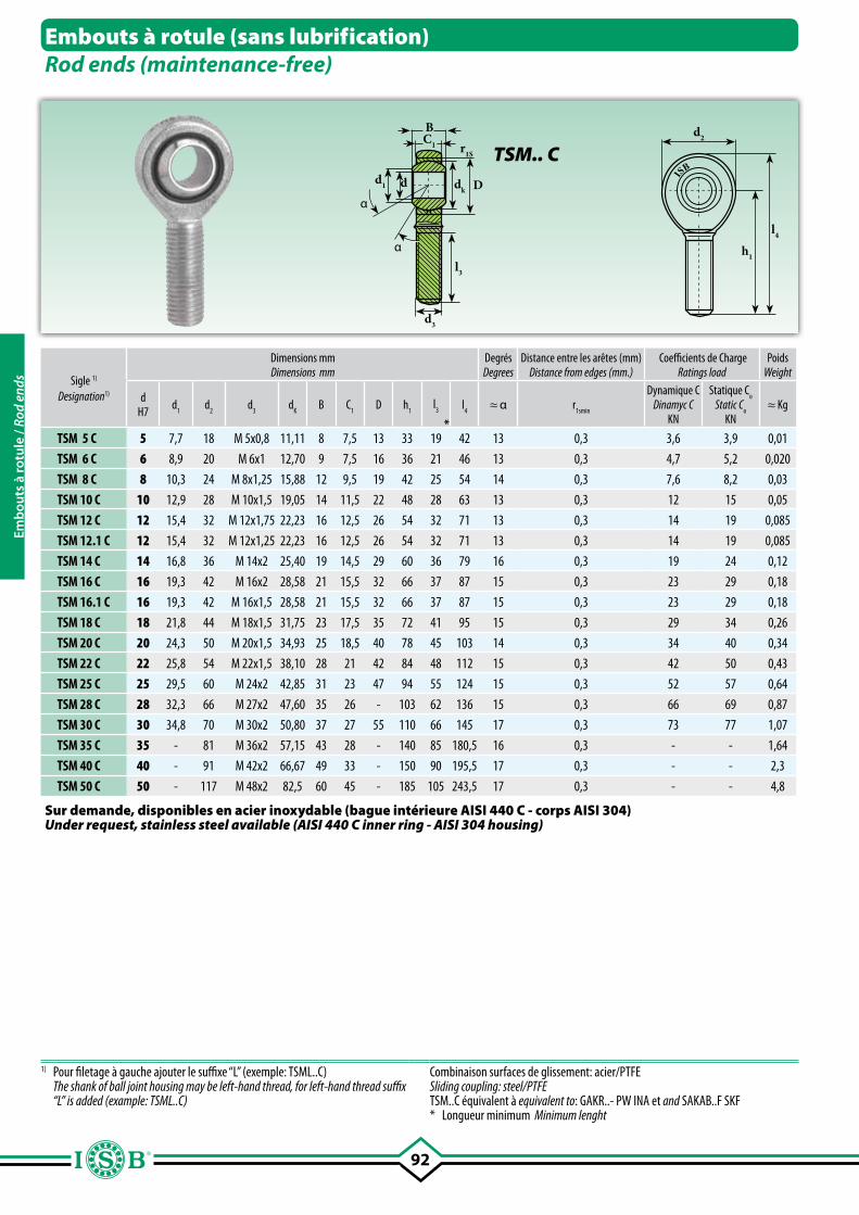
92
d2
h1
l4
dd1
d3
BC1
l3
r1S
dk Dα
α
ISB
Embouts à rotule (sans lubrification)Rod ends (maintenance-free)
TSM.. C
Sigle 1)
Designation1)
Dimensions mmDimensions mm
DegrésDegrees
Distance entre les arêtes (mm)Distance from edges (mm.)
Coefficients de ChargeRatings load
PoidsWeight
dH7 d
1d
2d
3d
KB C
1D h
1l
3
*
l4
≈ α r1smin
Dynamique CDinamyc C
KN
Statique Co
Static Co
KN≈ Kg
TSM 5 C 5 7,7 18 M 5x0,8 11,11 8 7,5 13 33 19 42 13 0,3 3,6 3,9 0,01
TSM 6 C 6 8,9 20 M 6x1 12,70 9 7,5 16 36 21 46 13 0,3 4,7 5,2 0,020
TSM 8 C 8 10,3 24 M 8x1,25 15,88 12 9,5 19 42 25 54 14 0,3 7,6 8,2 0,03
TSM 10 C 10 12,9 28 M 10x1,5 19,05 14 11,5 22 48 28 63 13 0,3 12 15 0,05
TSM 12 C 12 15,4 32 M 12x1,75 22,23 16 12,5 26 54 32 71 13 0,3 14 19 0,085
TSM 12.1 C 12 15,4 32 M 12x1,25 22,23 16 12,5 26 54 32 71 13 0,3 14 19 0,085
TSM 14 C 14 16,8 36 M 14x2 25,40 19 14,5 29 60 36 79 16 0,3 19 24 0,12
TSM 16 C 16 19,3 42 M 16x2 28,58 21 15,5 32 66 37 87 15 0,3 23 29 0,18
TSM 16.1 C 16 19,3 42 M 16x1,5 28,58 21 15,5 32 66 37 87 15 0,3 23 29 0,18
TSM 18 C 18 21,8 44 M 18x1,5 31,75 23 17,5 35 72 41 95 15 0,3 29 34 0,26
TSM 20 C 20 24,3 50 M 20x1,5 34,93 25 18,5 40 78 45 103 14 0,3 34 40 0,34
TSM 22 C 22 25,8 54 M 22x1,5 38,10 28 21 42 84 48 112 15 0,3 42 50 0,43
TSM 25 C 25 29,5 60 M 24x2 42,85 31 23 47 94 55 124 15 0,3 52 57 0,64
TSM 28 C 28 32,3 66 M 27x2 47,60 35 26 - 103 62 136 15 0,3 66 69 0,87
TSM 30 C 30 34,8 70 M 30x2 50,80 37 27 55 110 66 145 17 0,3 73 77 1,07
TSM 35 C 35 - 81 M 36x2 57,15 43 28 - 140 85 180,5 16 0,3 - - 1,64
TSM 40 C 40 - 91 M 42x2 66,67 49 33 - 150 90 195,5 17 0,3 - - 2,3
TSM 50 C 50 - 117 M 48x2 82,5 60 45 - 185 105 243,5 17 0,3 - - 4,8
1) Pour filetage à gauche ajouter le suffixe “L” (exemple: TSML..C) The shank of ball joint housing may be left-hand thread, for left-hand thread suffix
“L” is added (example: TSML..C)
Combinaison surfaces de glissement: acier/PTFESliding coupling: steel/PTFETSM..C équivalent à equivalent to: GAKR..- PW INA et and SAKAB..F SKF* Longueur minimum Minimum lenght
Sur demande, disponibles en acier inoxydable (bague intérieure AISI 440 C - corps AISI 304)Under request, stainless steel available (AISI 440 C inner ring - AISI 304 housing)
Emb
outs
à ro
tule
/ Ro
d en
ds
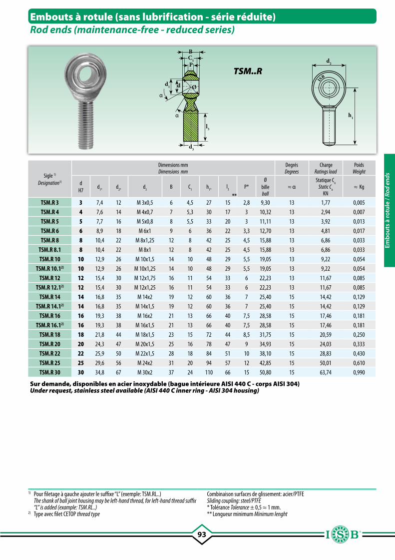
93
d2
h1
P
α
α
dd1
BC1
d3
l3
Ø
ISB
Embouts à rotule (sans lubrification - série réduite)Rod ends (maintenance-free - reduced series)
TSM..R
Sigle 1)
Designation1)
Dimensions mmDimensions mm
DegrésDegrees
ChargeRatings load
PoidsWeight
dH7
d1*
d2*
d3
B C1
h1*
l3
**
P*Ø
billeball
≈ αStatique C
oStatic C
oKN
≈ Kg
TSM.R 3 3 7,4 12 M 3x0,5 6 4,5 27 15 2,8 9,30 13 1,77 0,005
TSM.R 4 4 7,6 14 M 4x0,7 7 5,3 30 17 3 10,32 13 2,94 0,007
TSM.R 5 5 7,7 16 M 5x0,8 8 5,5 33 20 3 11,11 13 3,92 0,013
TSM.R 6 6 8,9 18 M 6x1 9 6 36 22 3,3 12,70 13 4,81 0,017
TSM.R 8 8 10,4 22 M 8x1,25 12 8 42 25 4,5 15,88 13 6,86 0,033
TSM.R 8.1 8 10,4 22 M 8x1 12 8 42 25 4,5 15,88 13 6,86 0,033
TSM.R 10 10 12,9 26 M 10x1,5 14 10 48 29 5,5 19,05 13 9,22 0,054
TSM.R 10.12) 10 12,9 26 M 10x1,25 14 10 48 29 5,5 19,05 13 9,22 0,054
TSM.R 12 12 15,4 30 M 12x1,75 16 11 54 33 6 22,23 13 11,67 0,085
TSM.R 12.12) 12 15,4 30 M 12x1,25 16 11 54 33 6 22,23 13 11,67 0,085
TSM.R 14 14 16,8 35 M 14x2 19 12 60 36 7 25,40 15 14,42 0,129
TSM.R 14.12) 14 16,8 35 M 14x1,5 19 12 60 36 7 25,40 15 14,42 0,129
TSM.R 16 16 19,3 38 M 16x2 21 13 66 40 7,5 28,58 15 17,46 0,181
TSM.R 16.12) 16 19,3 38 M 16x1,5 21 13 66 40 7,5 28,58 15 17,46 0,181
TSM.R 18 18 21,8 44 M 18x1,5 23 15 72 44 8,5 31,75 15 20,59 0,250
TSM.R 20 20 24,3 47 M 20x1,5 25 16 78 47 9 34,93 15 24,03 0,333
TSM.R 22 22 25,9 50 M 22x1,5 28 18 84 51 10 38,10 15 28,83 0,430
TSM.R 25 25 29,6 56 M 24x2 31 20 94 57 12 42,85 15 50,01 0,610
TSM.R 30 30 34,8 67 M 30x2 37 24 110 66 15 50,80 15 63,74 0,990
1) Pour filetage à gauche ajouter le suffixe “L” (exemple: TSM.RL..) The shank of ball joint housing may be left-hand thread, for left-hand thread suffix
“L” is added (example: TSM.RL..)2) Type avec filet CETOP thread type
Combinaison surfaces de glissement: acier/PTFESliding coupling: steel/PTFE* Tolérance Tolerance ± 0,5 ≈ 1 mm.** Longueur minimum Minimum lenght
Sur demande, disponibles en acier inoxydable (bague intérieure AISI 440 C - corps AISI 304)Under request, stainless steel available (AISI 440 C inner ring - AISI 304 housing)
Emb
outs
à ro
tule
/ Ro
d en
ds
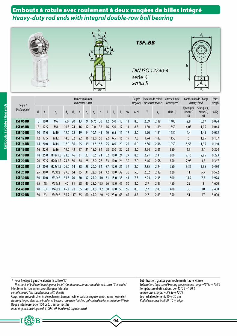
94
b1
b3
l3
d4d1
d3
sw
l1
l
d6
d2
d7
h
α
Embouts à rotule avec roulement à deux rangées de billes intégréHeavy-duty rod ends with integral double-row ball bearing
Sigle 1)
Designation1)
Dimensions mmDimensions mm
DegrésDegrees
Facteurs de calculCalculation factors
Vitesse limiteLimit speed
Coefficients de ChargeRatings load
PoidsWeight
d1
d2
d3
d4
d6
d7
b1
b3
h l l1
l3
sw ≈ α Y Y0
(Min -1)Dynamique C
Dinamyc CKN
Statique Co
Static Co
KN≈ Kg
TSF 06 BB 6 10.0 M6 9.0 20 13 9 6.75 30 12 5.0 10 11 8.0 2.09 2.19 1400 2,8 0,67 0.024
TSF 08 BB 8 12.5 M8 10.5 24 16 12 9.0 36 16 5.0 12 14 8.5 1.80 1.89 1350 4,05 1,05 0.044
TSF 10 BB 10 15.0 M10 12.0 28 19 14 10.5 43 20 6,5 15 17 8.0 1.90 1.81 1250 4,4 1,45 0.072
TSF 12 BB 12 17.5 M12 14.5 32 22 16 12.0 50 22 6.5 16 19 7.5 1.74 1.82 1150 5 1,85 0.107
TSF 14 BB 14 20.0 M14 17.0 36 25 19 13.5 57 25 8.0 20 22 6.0 2.36 2.48 1050 5,55 1,95 0.160
TSF 16 BB 16 22.0 M16 19.0 42 27 21 15.0 64 28 8.0 22 22 8.0 2.24 2.35 950 6,3 2,4 0.224
TSF 18 BB 18 25.0 M18x1.5 21.5 46 31 23 16.5 71 32 10.0 24 27 8.5 2.21 2.31 900 7,15 2,95 0.293
TSF 20 BB 20 27.5 M20x1.5 24.5 50 34 25 18.0 77 33 10.0 26 30 7.0 2.46 2.58 850 7,98 3,5 0.367
TSF 22 BB 22 30.0 M22x1.5 26.0 54 38 28 20.0 84 37 12.0 26 32 8.0 2.35 2.24 750 9,35 3,95 0.480
TSF 25 BB 25 30.0 M24x2 29.5 64 35 31 22.0 94 42 10.0 32 30 5.0 2.02 2.12 620 11 5,7 0.572
TSF 30 BB 30 40.0 M30x2 34.5 70 50 37 25.0 110 51 15.0 35 41 7.5 2.24 2.35 500 14,2 7,5 0.978
TSF 35 BB 35 48 M36x2 40 81 58 43 28.0 125 56 17.0 45 50 8.0 2.7 2.83 450 25 8 1.600
TSF 40 BB 40 53 M48x2 45.1 91 65 49 33.0 142 60 19.0 50 55 8.0 2.7 2.83 400 30 10 2.400
TSF 50 BB 50 63 M48x2 56.7 117 75 60 45.0 160 65 23.0 65 65 8.5 2.7 2.83 350 51 17 5.000
1) Pour filetage à gauche ajouter le suffixe “L” The shank of ball joint housing may be left-hand thread, for left-hand thread suffix “L” is addedFilet femelle, roulement avec flasques latéralesFemale thread low maintenance with shieldsCorps: acier embouti; chemin de roulement trempé, rectifié, surface zinguée, sans chrome hexavalentHousing forged steel case-hardened bearing race superfinished galvanized surface chromium VI freeBague intérieure: acier 100 Cr 6; trempé, rectifié Inner ring ball bearing steel: (100 Cr 6); hardened, superfinished
Lubrification: graisse pour roulements haute vitesseLubrication: high speed bearing grease (temp. range -45° to +120°) Température d'utilisation : de -45°C à +120°CTemperature range: -45°C to +120°CJeu radial roulement: 10 ÷ 30 µmRadial clearance (radial): 10 ÷ 30 µm
TSF..BB
DIN ISO 12240-4série Kseries K
Emb
outs
à ro
tule
/ Ro
d en
ds
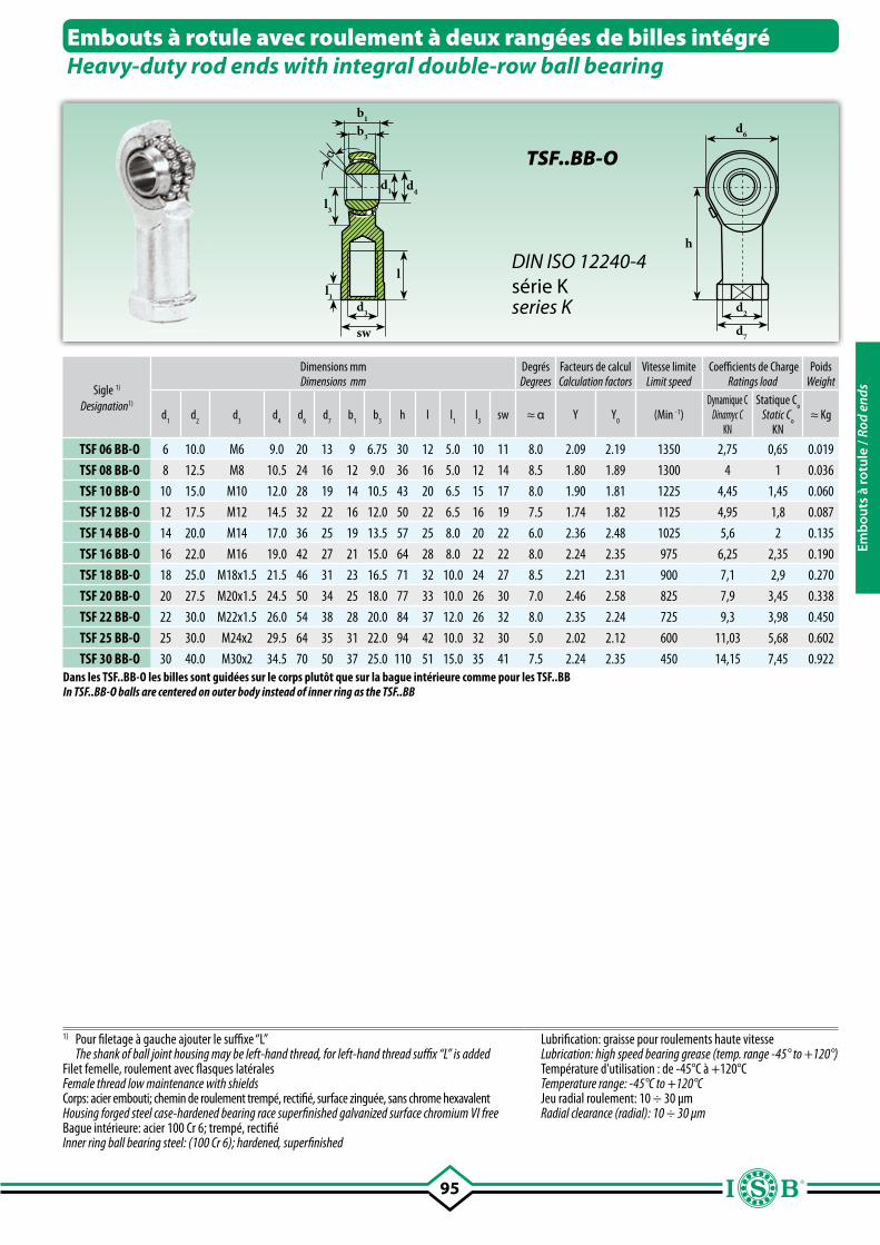
95
b1
b3
l3
d4d1
d3
sw
l1
l
d6
d2
d7
h
α
Embouts à rotule avec roulement à deux rangées de billes intégréHeavy-duty rod ends with integral double-row ball bearing
Sigle 1)
Designation1)
Dimensions mmDimensions mm
DegrésDegrees
Facteurs de calculCalculation factors
Vitesse limiteLimit speed
Coefficients de ChargeRatings load
PoidsWeight
d1
d2
d3
d4
d6
d7
b1
b3
h l l1
l3
sw ≈ α Y Y0
(Min -1)Dynamique C
Dinamyc CKN
Statique Co
Static Co
KN≈ Kg
TSF 06 BB-O 6 10.0 M6 9.0 20 13 9 6.75 30 12 5.0 10 11 8.0 2.09 2.19 1350 2,75 0,65 0.019
TSF 08 BB-O 8 12.5 M8 10.5 24 16 12 9.0 36 16 5.0 12 14 8.5 1.80 1.89 1300 4 1 0.036
TSF 10 BB-O 10 15.0 M10 12.0 28 19 14 10.5 43 20 6.5 15 17 8.0 1.90 1.81 1225 4,45 1,45 0.060
TSF 12 BB-O 12 17.5 M12 14.5 32 22 16 12.0 50 22 6.5 16 19 7.5 1.74 1.82 1125 4,95 1,8 0.087
TSF 14 BB-O 14 20.0 M14 17.0 36 25 19 13.5 57 25 8.0 20 22 6.0 2.36 2.48 1025 5,6 2 0.135
TSF 16 BB-O 16 22.0 M16 19.0 42 27 21 15.0 64 28 8.0 22 22 8.0 2.24 2.35 975 6,25 2,35 0.190
TSF 18 BB-O 18 25.0 M18x1.5 21.5 46 31 23 16.5 71 32 10.0 24 27 8.5 2.21 2.31 900 7,1 2,9 0.270
TSF 20 BB-O 20 27.5 M20x1.5 24.5 50 34 25 18.0 77 33 10.0 26 30 7.0 2.46 2.58 825 7,9 3,45 0.338
TSF 22 BB-O 22 30.0 M22x1.5 26.0 54 38 28 20.0 84 37 12.0 26 32 8.0 2.35 2.24 725 9,3 3,98 0.450
TSF 25 BB-O 25 30.0 M24x2 29.5 64 35 31 22.0 94 42 10.0 32 30 5.0 2.02 2.12 600 11,03 5,68 0.602
TSF 30 BB-O 30 40.0 M30x2 34.5 70 50 37 25.0 110 51 15.0 35 41 7.5 2.24 2.35 450 14,15 7,45 0.922
1) Pour filetage à gauche ajouter le suffixe “L” The shank of ball joint housing may be left-hand thread, for left-hand thread suffix “L” is addedFilet femelle, roulement avec flasques latéralesFemale thread low maintenance with shieldsCorps: acier embouti; chemin de roulement trempé, rectifié, surface zinguée, sans chrome hexavalentHousing forged steel case-hardened bearing race superfinished galvanized surface chromium VI freeBague intérieure: acier 100 Cr 6; trempé, rectifié Inner ring ball bearing steel: (100 Cr 6); hardened, superfinished
Lubrification: graisse pour roulements haute vitesseLubrication: high speed bearing grease (temp. range -45° to +120°)Température d'utilisation : de -45°C à +120°CTemperature range: -45°C to +120°CJeu radial roulement: 10 ÷ 30 µmRadial clearance (radial): 10 ÷ 30 µm
TSF..BB-O
DIN ISO 12240-4série Kseries K
Dans les TSF..BB-O les billes sont guidées sur le corps plutôt que sur la bague intérieure comme pour les TSF..BBIn TSF..BB-O balls are centered on outer body instead of inner ring as the TSF..BB
Emb
outs
à ro
tule
/ Ro
d en
ds
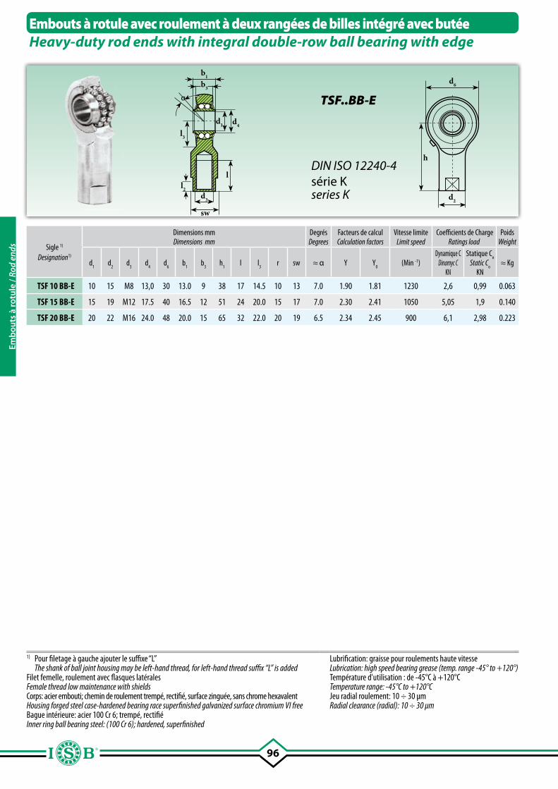
96
b1
b3
l3
d4d1
d3
sw
l2
l
d6
d2
h
α
Embouts à rotule avec roulement à deux rangées de billes intégré avec butéeHeavy-duty rod ends with integral double-row ball bearing with edge
Sigle 1)
Designation1)
Dimensions mmDimensions mm
DegrésDegrees
Facteurs de calculCalculation factors
Vitesse limiteLimit speed
Coefficients de ChargeRatings load
PoidsWeight
d1
d2
d3
d4
d6
b1
b3
h1
l l3
r sw ≈ α Y Y0
(Min -1)Dynamique C
Dinamyc CKN
Statique Co
Static Co
KN≈ Kg
TSF 10 BB-E 10 15 M8 13,0 30 13.0 9 38 17 14.5 10 13 7.0 1.90 1.81 1230 2,6 0,99 0.063
TSF 15 BB-E 15 19 M12 17.5 40 16.5 12 51 24 20.0 15 17 7.0 2.30 2.41 1050 5,05 1,9 0.140
TSF 20 BB-E 20 22 M16 24.0 48 20.0 15 65 32 22.0 20 19 6.5 2.34 2.45 900 6,1 2,98 0.223
1) Pour filetage à gauche ajouter le suffixe “L” The shank of ball joint housing may be left-hand thread, for left-hand thread suffix “L” is addedFilet femelle, roulement avec flasques latéralesFemale thread low maintenance with shieldsCorps: acier embouti; chemin de roulement trempé, rectifié, surface zinguée, sans chrome hexavalentHousing forged steel case-hardened bearing race superfinished galvanized surface chromium VI freeBague intérieure: acier 100 Cr 6; trempé, rectifié Inner ring ball bearing steel: (100 Cr 6); hardened, superfinished
Lubrification: graisse pour roulements haute vitesseLubrication: high speed bearing grease (temp. range -45° to +120°)Température d'utilisation : de -45°C à +120°CTemperature range: -45°C to +120°CJeu radial roulement: 10 ÷ 30 µmRadial clearance (radial): 10 ÷ 30 µm
TSF..BB-E
DIN ISO 12240-4série Kseries K
Emb
outs
à ro
tule
/ Ro
d en
ds
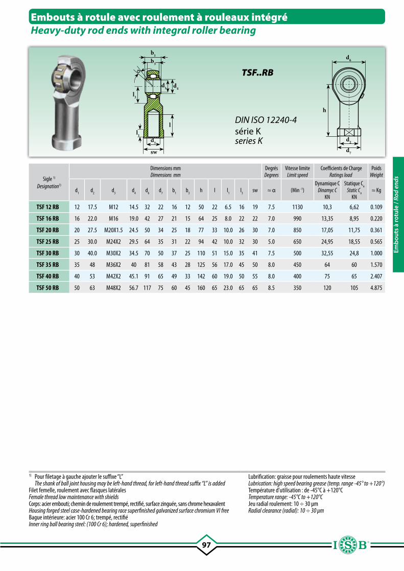
97
b1
b3
l3
d4d1
d3
sw
l1
l
d6
d2
d7
h
α
Embouts à rotule avec roulement à rouleaux intégréHeavy-duty rod ends with integral roller bearing
Sigle 1)
Designation1)
Dimensions mmDimensions mm
DegrésDegrees
Vitesse limiteLimit speed
Coefficients de ChargeRatings load
PoidsWeight
d1
d2
d3
d4
d6
d7
b1
b3
h l l1
l3
sw ≈ α (Min -1)Dynamique C
Dinamyc CKN
Statique Co
Static Co
KN≈ Kg
TSF 12 RB 12 17.5 M12 14.5 32 22 16 12 50 22 6.5 16 19 7.5 1130 10,3 6,62 0.109
TSF 16 RB 16 22.0 M16 19.0 42 27 21 15 64 25 8.0 22 22 7.0 990 13,35 8,95 0.220
TSF 20 RB 20 27.5 M20X1.5 24.5 50 34 25 18 77 33 10.0 26 30 7.0 850 17,05 11,75 0.361
TSF 25 RB 25 30.0 M24X2 29.5 64 35 31 22 94 42 10.0 32 30 5.0 650 24,95 18,55 0.565
TSF 30 RB 30 40.0 M30X2 34.5 70 50 37 25 110 51 15.0 35 41 7.5 500 32,55 24,8 1.000
TSF 35 RB 35 48 M36X2 40 81 58 43 28 125 56 17.0 45 50 8.0 450 64 60 1.570
TSF 40 RB 40 53 M42X2 45.1 91 65 49 33 142 60 19.0 50 55 8.0 400 75 65 2.407
TSF 50 RB 50 63 M48X2 56.7 117 75 60 45 160 65 23.0 65 65 8.5 350 120 105 4.875
1) Pour filetage à gauche ajouter le suffixe “L” The shank of ball joint housing may be left-hand thread, for left-hand thread suffix “L” is addedFilet femelle, roulement avec flasques latéralesFemale thread low maintenance with shieldsCorps: acier embouti; chemin de roulement trempé, rectifié, surface zinguée, sans chrome hexavalentHousing forged steel case-hardened bearing race superfinished galvanized surface chromium VI freeBague intérieure: acier 100 Cr 6; trempé, rectifié Inner ring ball bearing steel: (100 Cr 6); hardened, superfinished
Lubrification: graisse pour roulements haute vitesseLubrication: high speed bearing grease (temp. range -45° to +120°) Température d'utilisation : de -45°C à +120°CTemperature range: -45°C to +120°CJeu radial roulement: 10 ÷ 30 µmRadial clearance (radial): 10 ÷ 30 µm
TSF..RB
DIN ISO 12240-4série Kseries K
Emb
outs
à ro
tule
/ Ro
d en
ds
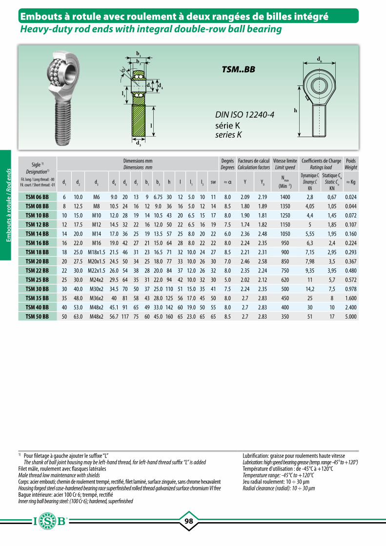
98
b1
b3
l3
d4d1
d3
l
d6
h
α
Embouts à rotule avec roulement à deux rangées de billes intégréHeavy-duty rod ends with integral double-row ball bearing
Sigle 1)
Designation1)
Fil. long / Long thread: -00Fil. court / Short thread: -01
Dimensions mmDimensions mm
DegrésDegrees
Facteurs de calculCalculation factors
Vitesse limiteLimit speed
Coefficients de ChargeRatings load
PoidsWeight
d1
d2
d3
d4
d6
d7
b1
b3
h l l1
l3
sw ≈ α Y Y0
Nmax
(Min -1)
Dynamique CDinamyc C
KN
Statique Co
Static Co
KN≈ Kg
TSM 06 BB 6 10.0 M6 9.0 20 13 9 6.75 30 12 5.0 10 11 8.0 2.09 2.19 1400 2,8 0,67 0.024
TSM 08 BB 8 12.5 M8 10.5 24 16 12 9.0 36 16 5.0 12 14 8.5 1.80 1.89 1350 4,05 1,05 0.044
TSM 10 BB 10 15.0 M10 12.0 28 19 14 10.5 43 20 6.5 15 17 8.0 1.90 1.81 1250 4,4 1,45 0.072
TSM 12 BB 12 17.5 M12 14.5 32 22 16 12.0 50 22 6.5 16 19 7.5 1.74 1.82 1150 5 1,85 0.107
TSM 14 BB 14 20.0 M14 17.0 36 25 19 13.5 57 25 8.0 20 22 6.0 2.36 2.48 1050 5,55 1,95 0.160
TSM 16 BB 16 22.0 M16 19.0 42 27 21 15.0 64 28 8.0 22 22 8.0 2.24 2.35 950 6,3 2,4 0.224
TSM 18 BB 18 25.0 M18x1.5 21.5 46 31 23 16.5 71 32 10.0 24 27 8.5 2.21 2.31 900 7,15 2,95 0.293
TSM 20 BB 20 27.5 M20x1.5 24.5 50 34 25 18.0 77 33 10.0 26 30 7.0 2.46 2.58 850 7,98 3,5 0.367
TSM 22 BB 22 30.0 M22x1.5 26.0 54 38 28 20.0 84 37 12.0 26 32 8.0 2.35 2.24 750 9,35 3,95 0.480
TSM 25 BB 25 30.0 M24x2 29.5 64 35 31 22.0 94 42 10.0 32 30 5.0 2.02 2.12 620 11 5,7 0.572
TSM 30 BB 30 40.0 M30x2 34.5 70 50 37 25.0 110 51 15.0 35 41 7.5 2.24 2.35 500 14,2 7,5 0.978
TSM 35 BB 35 48.0 M36x2 40 81 58 43 28.0 125 56 17.0 45 50 8.0 2.7 2.83 450 25 8 1.600
TSM 40 BB 40 53.0 M48x2 45.1 91 65 49 33.0 142 60 19.0 50 55 8.0 2.7 2.83 400 30 10 2.400
TSM 50 BB 50 63.0 M48x2 56.7 117 75 60 45.0 160 65 23.0 65 65 8.5 2.7 2.83 350 51 17 5.000
1) Pour filetage à gauche ajouter le suffixe “L” The shank of ball joint housing may be left-hand thread, for left-hand thread suffix “L” is addedFilet mâle, roulement avec flasques latéralesMale thread low maintenance with shieldsCorps: acier embouti; chemin de roulement trempé, rectifié, filet laminé, surface zinguée, sans chrome hexavalentHousing forged steel case-hardened bearing race superfinished rolled thread galvanized surface chromium VI freeBague intérieure: acier 100 Cr 6; trempé, rectifié Inner ring ball bearing steel: (100 Cr 6); hardened, superfinished
Lubrification: graisse pour roulements haute vitesseLubrication: high speed bearing grease (temp. range -45° to +120°)Température d'utilisation : de -45°C à +120°CTemperature range: -45°C to +120°CJeu radial roulement: 10 ÷ 30 µmRadial clearance (radial): 10 ÷ 30 µm
TSM..BB
DIN ISO 12240-4série Kseries K
Emb
outs
à ro
tule
/ Ro
d en
ds
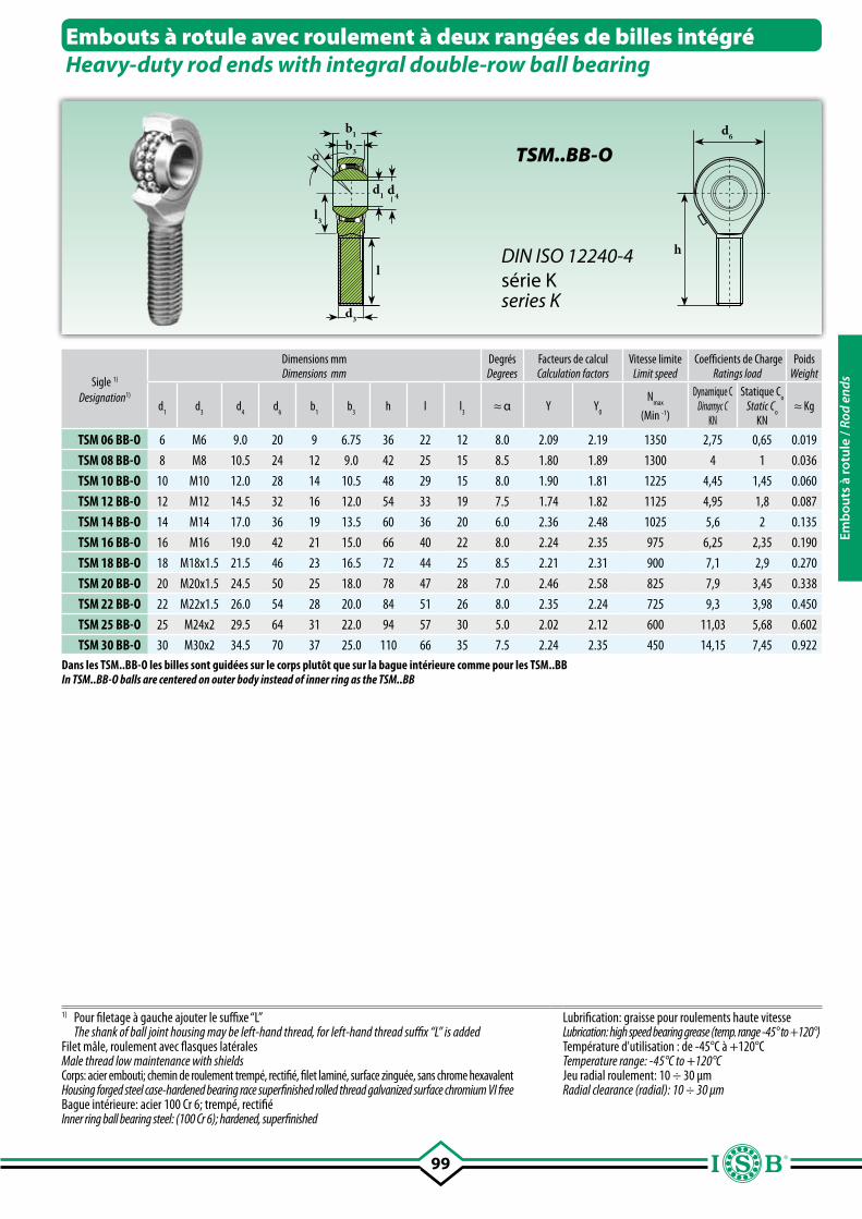
99
b1
b3
d3
l3
l
d4d1
d6
h
α
Embouts à rotule avec roulement à deux rangées de billes intégréHeavy-duty rod ends with integral double-row ball bearing
Sigle 1)
Designation1)
Dimensions mmDimensions mm
DegrésDegrees
Facteurs de calculCalculation factors
Vitesse limiteLimit speed
Coefficients de ChargeRatings load
PoidsWeight
d1
d3
d4
d6
b1
b3
h l l3
≈ α Y Y0
Nmax
(Min -1)
Dynamique CDinamyc C
KN
Statique Co
Static Co
KN≈ Kg
TSM 06 BB-O 6 M6 9.0 20 9 6.75 36 22 12 8.0 2.09 2.19 1350 2,75 0,65 0.019
TSM 08 BB-O 8 M8 10.5 24 12 9.0 42 25 15 8.5 1.80 1.89 1300 4 1 0.036
TSM 10 BB-O 10 M10 12.0 28 14 10.5 48 29 15 8.0 1.90 1.81 1225 4,45 1,45 0.060
TSM 12 BB-O 12 M12 14.5 32 16 12.0 54 33 19 7.5 1.74 1.82 1125 4,95 1,8 0.087
TSM 14 BB-O 14 M14 17.0 36 19 13.5 60 36 20 6.0 2.36 2.48 1025 5,6 2 0.135
TSM 16 BB-O 16 M16 19.0 42 21 15.0 66 40 22 8.0 2.24 2.35 975 6,25 2,35 0.190
TSM 18 BB-O 18 M18x1.5 21.5 46 23 16.5 72 44 25 8.5 2.21 2.31 900 7,1 2,9 0.270
TSM 20 BB-O 20 M20x1.5 24.5 50 25 18.0 78 47 28 7.0 2.46 2.58 825 7,9 3,45 0.338
TSM 22 BB-O 22 M22x1.5 26.0 54 28 20.0 84 51 26 8.0 2.35 2.24 725 9,3 3,98 0.450
TSM 25 BB-O 25 M24x2 29.5 64 31 22.0 94 57 30 5.0 2.02 2.12 600 11,03 5,68 0.602
TSM 30 BB-O 30 M30x2 34.5 70 37 25.0 110 66 35 7.5 2.24 2.35 450 14,15 7,45 0.922
1) Pour filetage à gauche ajouter le suffixe “L” The shank of ball joint housing may be left-hand thread, for left-hand thread suffix “L” is addedFilet mâle, roulement avec flasques latéralesMale thread low maintenance with shieldsCorps: acier embouti; chemin de roulement trempé, rectifié, filet laminé, surface zinguée, sans chrome hexavalentHousing forged steel case-hardened bearing race superfinished rolled thread galvanized surface chromium VI freeBague intérieure: acier 100 Cr 6; trempé, rectifié Inner ring ball bearing steel: (100 Cr 6); hardened, superfinished
Lubrification: graisse pour roulements haute vitesseLubrication: high speed bearing grease (temp. range -45° to +120°) Température d'utilisation : de -45°C à +120°CTemperature range: -45°C to +120°CJeu radial roulement: 10 ÷ 30 µmRadial clearance (radial): 10 ÷ 30 µm
TSM..BB-O
DIN ISO 12240-4série Kseries K
Dans les TSM..BB-O les billes sont guidées sur le corps plutôt que sur la bague intérieure comme pour les TSM..BBIn TSM..BB-O balls are centered on outer body instead of inner ring as the TSM..BB
Emb
outs
à ro
tule
/ Ro
d en
ds
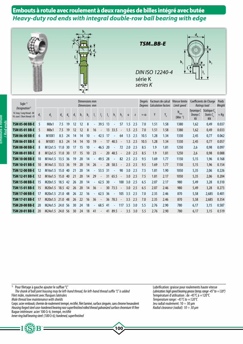
100
b1
b3
l3
d4d1
d3
d7
d6
h1 h2zl1
l2
n
α
Embouts à rotule avec roulement à deux rangées de billes intégré avec butéeHeavy-duty rod ends with integral double-row ball bearing with edge
Sigle 1)
Designation1)
Fil. long / Long thread: -00Fil. court / Short thread: -01
Dimensions mmDimensions mm
DegrésDegrees
Facteurs de calculCalculation factors
Vitesse limiteLimit speed
Coefficients de ChargeRatings load
PoidsWeight
d1
d3
d4
d6
d7
b1
b3
l1
l2
l3
h1
h2
u z ≈ α Y Y0
Nmax
(Min -1)
Dynamique CDinamyc C
KN
Statique Co
Static Co
KN≈ Kg
TSM 05-00 BB-E 5 M8x1 7.5 19 12 12 8 - 39.5 13 - 57 1.5 2.5 7.0 1.51 1.58 1380 1,62 0,49 0.037
TSM 05-01 BB-E 5 M8x1 7.5 19 12 12 8 16 - 13 33.5 - 1.5 2.5 7.0 1.51 1.58 1380 1,62 0,49 0.033
TSM 06-00 BB-E 6 M10X1 8.5 24 14 14 10 - 42.5 17 - 64 1.5 2.5 10.5 1.28 1.34 1330 2,45 0,77 0.062
TSM 06-01 BB-E 6 M10X1 8.5 24 14 14 10 19 - 17 40.5 - 1.5 2.5 10.5 1.28 1.34 1330 2,45 0,77 0.057
TSM 08-00 BB-E 8 M12x1.5 11.0 30 17 15 10 - 46.5 20 - 72 2.0 2.5 8.5 1.9 1.81 1250 2,6 0,98 0.097
TSM 08-01 BB-E 8 M12x1.5 11.0 30 17 15 10 23 - 20 48.5 - 2.0 2.5 8.5 1.9 1.81 1250 2,6 0,98 0.088
TSM 10-00 BB-E 10 M14x1.5 13.5 36 19 20 14 - 49.5 28 - 82 2.5 2.5 9.5 1.69 1.77 1150 5,15 1,96 0.168
TSM 10-01 BB-E 10 M14x1.5 13.5 36 19 20 14 26 - 28 58.5 - 2.5 2.5 9.5 1.69 1.77 1150 5,15 1,96 0.154
TSM 12-00 BB-E 12 M16x1.5 15.0 40 21 20 14 - 53.5 31 - 90 3.0 2.5 7.5 1.81 1.90 1050 5,35 2,06 0.226
TSM 12-01 BB-E 12 M16x1.5 15.0 40 21 20 14 29 - 31 65.5 - 3.0 2.5 7.5 1.81 2.17 1050 5,35 2,06 0.204
TSM 15-00 BB-E 15 M20x1.5 18.5 42 26 20 14 - 62.5 30 - 100 3.0 2.5 6.5 2.07 2.17 980 5,49 3,28 0.310
TSM 15-01 BB-E 15 M20x1.5 18.5 42 26 20 14 36 - 30 73.5 - 3.0 2.5 6.5 2.07 2.46 980 5,49 3,28 0.273
TSM 17-00 BB-E 17 M20x1.5 21.0 48 26 22 16 - 62.5 36 - 105 3.5 2.5 7.0 2.35 2.46 870 5,58 2,685 0.401
TSM 17-01 BB-E 17 M20x1.5 21.0 48 26 22 16 36 - 36 78.5 - 3.5 2.5 7.0 2.35 2.46 870 5,58 2,685 0.354
TSM 20-00 BB-E 20 M24x1.5 24.0 56 30 24 18 - 68.5 41 - 117 3.5 3.0 5.5 2.76 2.90 780 6,17 3,15 0.587
TSM 20-01 BB-E 20 M24x1.5 24.0 56 30 24 18 41 - 41 89.5 - 3.5 3.0 5.5 2.76 2.90 780 6,17 3,15 0.519
1) Pour filetage à gauche ajouter le suffixe “L” The shank of ball joint housing may be left-hand thread, for left-hand thread suffix “L” is addedFilet mâle, roulement avec flasques latéralesMale thread low maintenance with shieldsCorps: acier embouti; chemin de roulement trempé, rectifié, filet laminé, surface zinguée, sans chrome hexavalentHousing forged steel case-hardened bearing race superfinished rolled thread galvanized surface chromium VI freeBague intérieure: acier 100 Cr 6; trempé, rectifié Inner ring ball bearing steel: (100 Cr 6); hardened, superfinished
Lubrification: graisse pour roulements haute vitesseLubrication: high speed bearing grease (temp. range -45° to +120°) Température d'utilisation : de -45°C à +120°CTemperature range: -45°C to +120°CJeu radial roulement: 10 ÷ 30 µmRadial clearance (radial): 10 ÷ 30 µm
TSM..BB-E
DIN ISO 12240-4série Kseries K
Emb
outs
à ro
tule
/ Ro
d en
ds
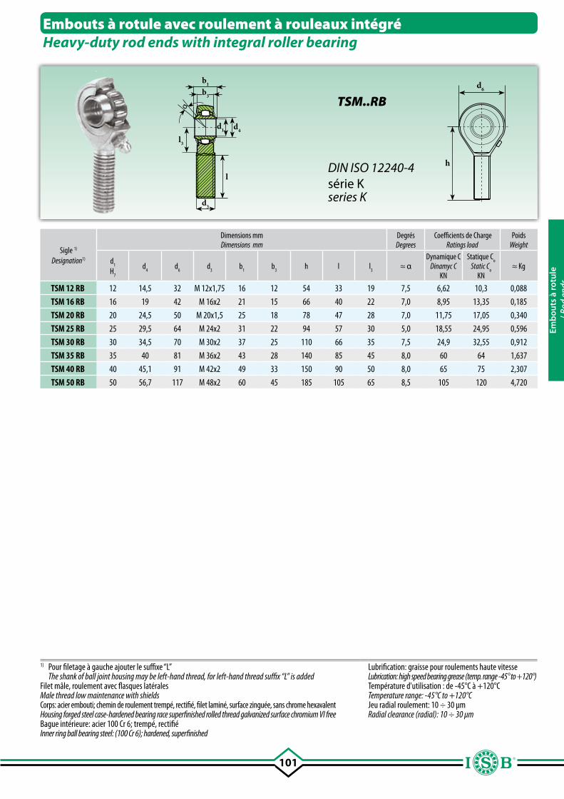
101
d6
h
b1
b3
l3
d4d1
d3
lα
Embouts à rotule avec roulement à rouleaux intégréHeavy-duty rod ends with integral roller bearing
Sigle 1)
Designation1)
Dimensions mmDimensions mm
DegrésDegrees
Coefficients de ChargeRatings load
PoidsWeight
d1
H7
d4
d6
d3
b1
b3
h l l3
≈ αDynamique C
Dinamyc CKN
Statique Co
Static Co
KN≈ Kg
TSM 12 RB 12 14,5 32 M 12x1,75 16 12 54 33 19 7,5 6,62 10,3 0,088
TSM 16 RB 16 19 42 M 16x2 21 15 66 40 22 7,0 8,95 13,35 0,185
TSM 20 RB 20 24,5 50 M 20x1,5 25 18 78 47 28 7,0 11,75 17,05 0,340
TSM 25 RB 25 29,5 64 M 24x2 31 22 94 57 30 5,0 18,55 24,95 0,596
TSM 30 RB 30 34,5 70 M 30x2 37 25 110 66 35 7,5 24,9 32,55 0,912
TSM 35 RB 35 40 81 M 36x2 43 28 140 85 45 8,0 60 64 1,637
TSM 40 RB 40 45,1 91 M 42x2 49 33 150 90 50 8,0 65 75 2,307
TSM 50 RB 50 56,7 117 M 48x2 60 45 185 105 65 8,5 105 120 4,720
1) Pour filetage à gauche ajouter le suffixe “L” The shank of ball joint housing may be left-hand thread, for left-hand thread suffix “L” is addedFilet mâle, roulement avec flasques latéralesMale thread low maintenance with shieldsCorps: acier embouti; chemin de roulement trempé, rectifié, filet laminé, surface zinguée, sans chrome hexavalentHousing forged steel case-hardened bearing race superfinished rolled thread galvanized surface chromium VI freeBague intérieure: acier 100 Cr 6; trempé, rectifié Inner ring ball bearing steel: (100 Cr 6); hardened, superfinished
Lubrification: graisse pour roulements haute vitesseLubrication: high speed bearing grease (temp. range -45° to +120°) Température d'utilisation : de -45°C à +120°CTemperature range: -45°C to +120°CJeu radial roulement: 10 ÷ 30 µmRadial clearance (radial): 10 ÷ 30 µm
TSM..RB
DIN ISO 12240-4série Kseries K
Emb
outs
à ro
tule
/ Ro
d en
ds
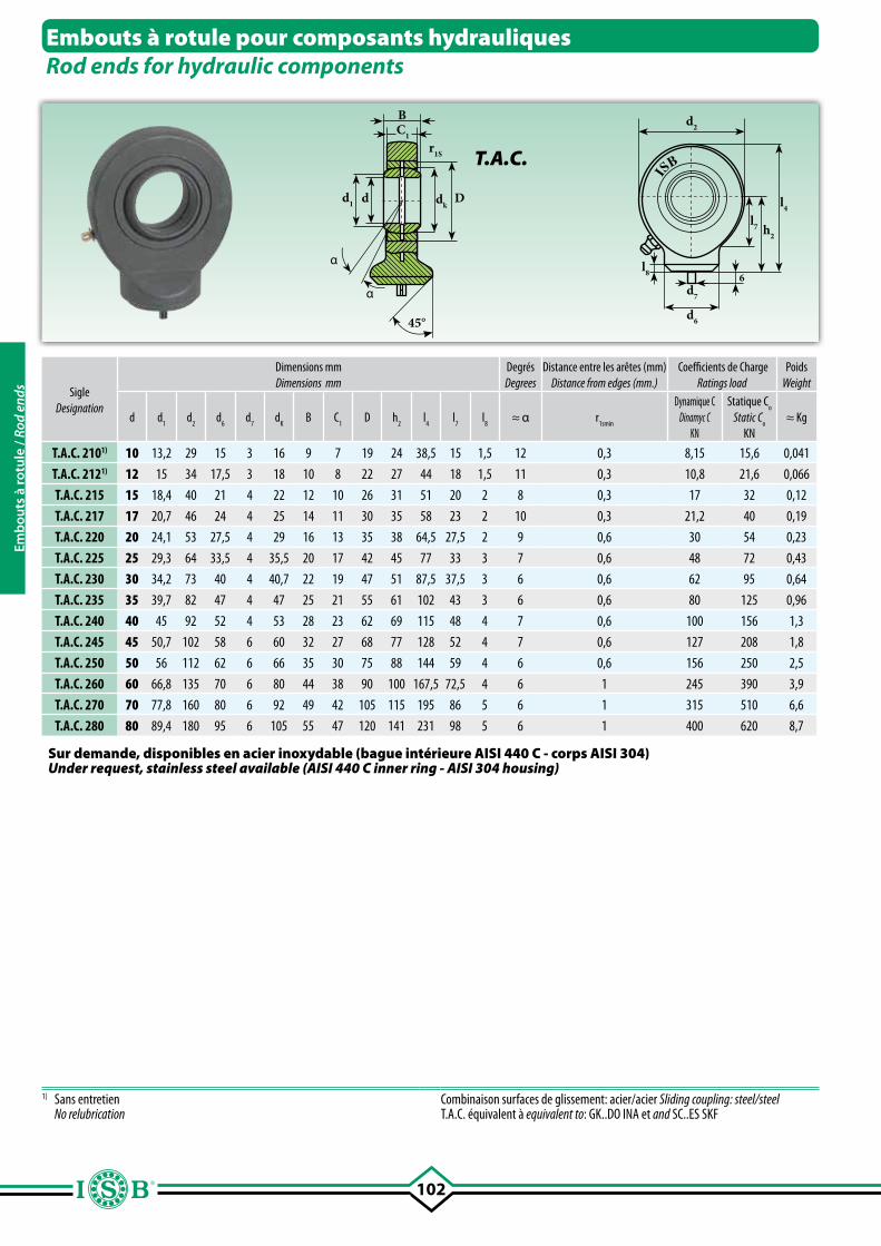
102
α
BC1
r1S
dkD
α
45°
dd1
d2
l8
d6
d7
6
l7 h2
l4
ISB
SigleDesignation
Dimensions mmDimensions mm
DegrésDegrees
Distance entre les arêtes (mm)Distance from edges (mm.)
Coefficients de ChargeRatings load
PoidsWeight
d d1 d
2 d
6 d
7 d
K B C
1D h
2l
4l
7l
8≈ α r
1smin
Dynamique CDinamyc C
KN
Statique Co
Static Co
KN≈ Kg
T.A.C. 2101) 10 13,2 29 15 3 16 9 7 19 24 38,5 15 1,5 12 0,3 8,15 15,6 0,041
T.A.C. 2121) 12 15 34 17,5 3 18 10 8 22 27 44 18 1,5 11 0,3 10,8 21,6 0,066
T.A.C. 215 15 18,4 40 21 4 22 12 10 26 31 51 20 2 8 0,3 17 32 0,12
T.A.C. 217 17 20,7 46 24 4 25 14 11 30 35 58 23 2 10 0,3 21,2 40 0,19
T.A.C. 220 20 24,1 53 27,5 4 29 16 13 35 38 64,5 27,5 2 9 0,6 30 54 0,23
T.A.C. 225 25 29,3 64 33,5 4 35,5 20 17 42 45 77 33 3 7 0,6 48 72 0,43
T.A.C. 230 30 34,2 73 40 4 40,7 22 19 47 51 87,5 37,5 3 6 0,6 62 95 0,64
T.A.C. 235 35 39,7 82 47 4 47 25 21 55 61 102 43 3 6 0,6 80 125 0,96
T.A.C. 240 40 45 92 52 4 53 28 23 62 69 115 48 4 7 0,6 100 156 1,3
T.A.C. 245 45 50,7 102 58 6 60 32 27 68 77 128 52 4 7 0,6 127 208 1,8
T.A.C. 250 50 56 112 62 6 66 35 30 75 88 144 59 4 6 0,6 156 250 2,5
T.A.C. 260 60 66,8 135 70 6 80 44 38 90 100 167,5 72,5 4 6 1 245 390 3,9
T.A.C. 270 70 77,8 160 80 6 92 49 42 105 115 195 86 5 6 1 315 510 6,6
T.A.C. 280 80 89,4 180 95 6 105 55 47 120 141 231 98 5 6 1 400 620 8,7
Embouts à rotule pour composants hydrauliquesRod ends for hydraulic components
T.A.C.
1) Sans entretien No relubrication
Combinaison surfaces de glissement: acier/acier Sliding coupling: steel/steelT.A.C. équivalent à equivalent to: GK..DO INA et and SC..ES SKF
Sur demande, disponibles en acier inoxydable (bague intérieure AISI 440 C - corps AISI 304)Under request, stainless steel available (AISI 440 C inner ring - AISI 304 housing)
Emb
outs
à ro
tule
/ Ro
d en
ds
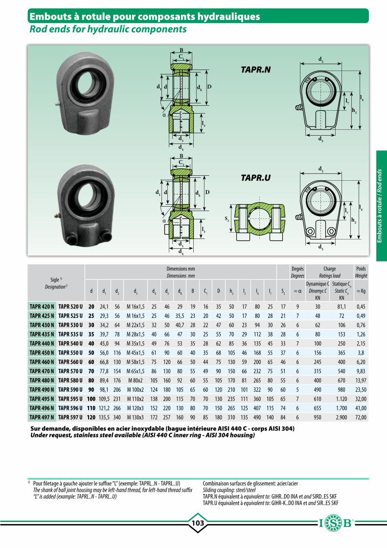
103
d2
l7
h2
l4
d5
α
dkDdd1
BC1
d3
d4
l3
d2
l7
h2
l4
d5
α
dkDdd1
BC1
d3
d4
l3
IS
B
IS
B
Sigle 1)
Designation1)
Dimensions mmDimensions mm
DegrésDegrees
ChargeRatings load
PoidsWeight
Dynamique CDinamyc C
KN
Statique Co
Static Co
KN≈ Kgd d
1d
2 d
3d
4d
5 d
KB C
1D h
2l
3l
4l
7S
2≈ α
TAPR 420 N TAPR 520 U 20 24,1 56 M 16x1,5 25 46 29 19 16 35 50 17 80 25 17 9 30 81,1 0,45
TAPR 425 N TAPR 525 U 25 29,3 56 M 16x1,5 25 46 35,5 23 20 42 50 17 80 28 21 7 48 72 0,49
TAPR 430 N TAPR 530 U 30 34,2 64 M 22x1,5 32 50 40,7 28 22 47 60 23 94 30 26 6 62 106 0,76
TAPR 435 N TAPR 535 U 35 39,7 78 M 28x1,5 40 66 47 30 25 55 70 29 112 38 28 6 80 153 1,26
TAPR 440 N TAPR 540 U 40 45,0 94 M 35x1,5 49 76 53 35 28 62 85 36 135 45 33 7 100 250 2,15
TAPR 450 N TAPR 550 U 50 56,0 116 M 45x1,5 61 90 60 40 35 68 105 46 168 55 37 6 156 365 3,8
TAPR 460 N TAPR 560 U 60 66,8 130 M 58x1,5 75 120 66 50 44 75 130 59 200 65 46 6 245 400 6,20
TAPR 470 N TAPR 570 U 70 77,8 154 M 65x1,5 86 130 80 55 49 90 150 66 232 75 51 6 315 540 9,83
TAPR 480 N TAPR 580 U 80 89,4 176 M 80x2 105 160 92 60 55 105 170 81 265 80 55 6 400 670 13,97
TAPR 490 N TAPR 590 U 90 98,1 206 M 100x2 124 180 105 65 60 120 210 101 322 90 60 5 490 980 23,50
TAPR 495 N TAPR 595 U 100 109,5 231 M 110x2 138 200 115 70 70 130 235 111 360 105 65 7 610 1.120 32,00
TAPR 496 N TAPR 596 U 110 121,2 266 M 120x3 152 220 130 80 70 150 265 125 407 115 74 6 655 1.700 41,00
TAPR 497 N TAPR 597 U 120 135,5 340 M 130x3 172 257 160 90 85 180 310 135 490 140 84 6 950 2.900 72,00
Embouts à rotule pour composants hydrauliquesRod ends for hydraulic components
TAPR.N
TAPR.U
1) Pour filetage à gauche ajouter le suffixe “L” (exemple: TAPRL..N - TAPRL..U) The shank of ball joint housing may be left-hand thread, for left-hand thread suffix
“L” is added (example: TAPRL..N - TAPRL..U)
Combinaison surfaces de glissement: acier/acierSliding coupling: steel/steelTAPR.N équivalent à equivalent to: GIHR..DO INA et and SIRD..ES SKFTAPR.U équivalent à equivalent to: GIHR-K..DO INA et and SIR..ES SKF
Sur demande, disponibles en acier inoxydable (bague intérieure AISI 440 C - corps AISI 304)Under request, stainless steel available (AISI 440 C inner ring - AISI 304 housing)
S2
Emb
outs
à ro
tule
/ Ro
d en
ds
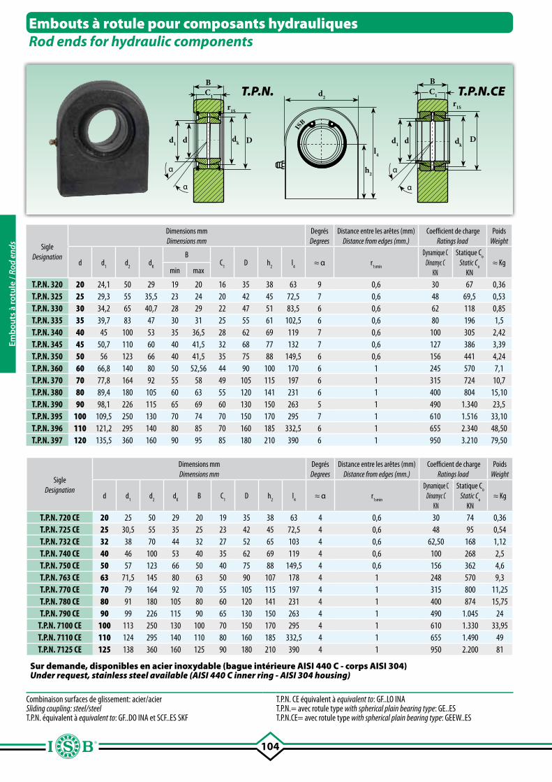
104
d2
h2
l4
α
r1S
dk Ddd1
α
BC1
r1S
dkD
BC1
α
dd1
α
IS
B
SigleDesignation
Dimensions mmDimensions mm
DegrésDegrees
Distance entre les arêtes (mm)Distance from edges (mm.)
Coefficient de chargeRatings load
Poids Weight
d d1 d
2 d
K
BC
1D h
2 l
4 ≈ α r
1smin
Dynamique CDinamyc C
KN
Statique Co
Static Co
KN≈ Kg
min max
T.P.N. 320 20 24,1 50 29 19 20 16 35 38 63 9 0,6 30 67 0,36T.P.N. 325 25 29,3 55 35,5 23 24 20 42 45 72,5 7 0,6 48 69,5 0,53T.P.N. 330 30 34,2 65 40,7 28 29 22 47 51 83,5 6 0,6 62 118 0,85T.P.N. 335 35 39,7 83 47 30 31 25 55 61 102,5 6 0,6 80 196 1,5T.P.N. 340 40 45 100 53 35 36,5 28 62 69 119 7 0,6 100 305 2,42T.P.N. 345 45 50,7 110 60 40 41,5 32 68 77 132 7 0,6 127 386 3,39T.P.N. 350 50 56 123 66 40 41,5 35 75 88 149,5 6 0,6 156 441 4,24T.P.N. 360 60 66,8 140 80 50 52,56 44 90 100 170 6 1 245 570 7,1T.P.N. 370 70 77,8 164 92 55 58 49 105 115 197 6 1 315 724 10,7T.P.N. 380 80 89,4 180 105 60 63 55 120 141 231 6 1 400 804 15,10T.P.N. 390 90 98,1 226 115 65 69 60 130 150 263 5 1 490 1.340 23,5T.P.N. 395 100 109,5 250 130 70 74 70 150 170 295 7 1 610 1.516 33,10T.P.N. 396 110 121,2 295 140 80 85 70 160 185 332,5 6 1 655 2.340 48,50T.P.N. 397 120 135,5 360 160 90 95 85 180 210 390 6 1 950 3.210 79,50
Embouts à rotule pour composants hydrauliquesRod ends for hydraulic components
T.P.N.
Combinaison surfaces de glissement: acier/acierSliding coupling: steel/steelT.P.N. équivalent à equivalent to: GF..DO INA et SCF..ES SKF
T.P.N. CE équivalent à equivalent to: GF..LO INAT.P.N.= avec rotule type with spherical plain bearing type: GE..EST.P.N.CE= avec rotule type with spherical plain bearing type: GEEW..ES
SigleDesignation
Dimensions mmDimensions mm
DegrésDegrees
Distance entre les arêtes (mm)Distance from edges (mm.)
Coefficient de chargeRatings load
Poids Weight
d d1 d
2 d
K B C
1D h
2 l
4 ≈ α r
1smin
Dynamique CDinamyc C
KN
Statique Co
Static Co
KN≈ Kg
T.P.N. 720 CE 20 25 50 29 20 19 35 38 63 4 0,6 30 74 0,36T.P.N. 725 CE 25 30,5 55 35 25 23 42 45 72,5 4 0,6 48 95 0,54T.P.N. 732 CE 32 38 70 44 32 27 52 65 103 4 0,6 62,50 168 1,12T.P.N. 740 CE 40 46 100 53 40 35 62 69 119 4 0,6 100 268 2,5T.P.N. 750 CE 50 57 123 66 50 40 75 88 149,5 4 0,6 156 362 4,6T.P.N. 763 CE 63 71,5 145 80 63 50 90 107 178 4 1 248 570 9,3T.P.N. 770 CE 70 79 164 92 70 55 105 115 197 4 1 315 800 11,25T.P.N. 780 CE 80 91 180 105 80 60 120 141 231 4 1 400 874 15,75T.P.N. 790 CE 90 99 226 115 90 65 130 150 263 4 1 490 1.045 24
T.P.N. 7100 CE 100 113 250 130 100 70 150 170 295 4 1 610 1.330 33,95T.P.N. 7110 CE 110 124 295 140 110 80 160 185 332,5 4 1 655 1.490 49T.P.N. 7125 CE 125 138 360 160 125 90 180 210 390 4 1 950 2.200 81
Sur demande, disponibles en acier inoxydable (bague intérieure AISI 440 C - corps AISI 304)Under request, stainless steel available (AISI 440 C inner ring - AISI 304 housing)
T.P.N.CE
Emb
outs
à ro
tule
/ Ro
d en
ds
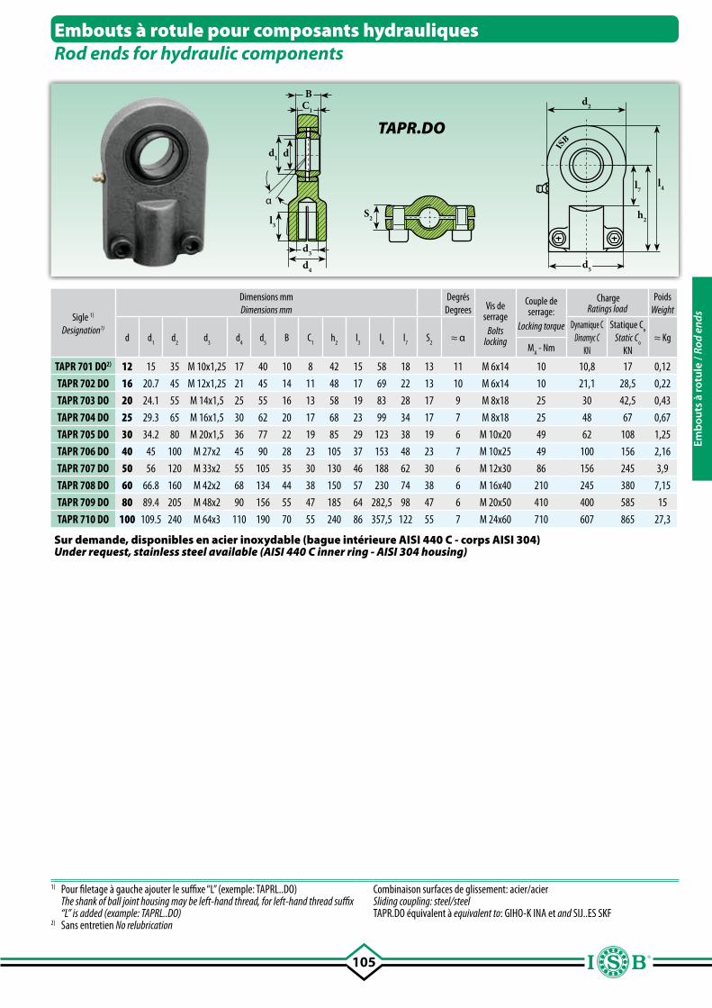
105
α
IS
B
Embouts à rotule pour composants hydrauliquesRod ends for hydraulic components
Sigle 1)
Designation1)
Dimensions mmDimensions mm
DegrésDegrees Vis de
serrageBolts
locking
Couple de serrage:
Locking torque
ChargeRatings load
PoidsWeight
d d1
d2 d
3d
4d
5B C
1h
2l
3l
4l
7S
2≈ α
Dynamique CDinamyc C
KN
Statique Co
Static Co
KN≈ Kg
MA - Nm
TAPR 701 DO2) 12 15 35 M 10x1,25 17 40 10 8 42 15 58 18 13 11 M 6x14 10 10,8 17 0,12
TAPR 702 DO 16 20.7 45 M 12x1,25 21 45 14 11 48 17 69 22 13 10 M 6x14 10 21,1 28,5 0,22
TAPR 703 DO 20 24.1 55 M 14x1,5 25 55 16 13 58 19 83 28 17 9 M 8x18 25 30 42,5 0,43
TAPR 704 DO 25 29.3 65 M 16x1,5 30 62 20 17 68 23 99 34 17 7 M 8x18 25 48 67 0,67
TAPR 705 DO 30 34.2 80 M 20x1,5 36 77 22 19 85 29 123 38 19 6 M 10x20 49 62 108 1,25
TAPR 706 DO 40 45 100 M 27x2 45 90 28 23 105 37 153 48 23 7 M 10x25 49 100 156 2,16
TAPR 707 DO 50 56 120 M 33x2 55 105 35 30 130 46 188 62 30 6 M 12x30 86 156 245 3,9
TAPR 708 DO 60 66.8 160 M 42x2 68 134 44 38 150 57 230 74 38 6 M 16x40 210 245 380 7,15
TAPR 709 DO 80 89.4 205 M 48x2 90 156 55 47 185 64 282,5 98 47 6 M 20x50 410 400 585 15
TAPR 710 DO 100 109.5 240 M 64x3 110 190 70 55 240 86 357,5 122 55 7 M 24x60 710 607 865 27,3
S2 h2
l4
d5
d2
l3
BC1
dd1
d4
d3
TAPR.DO
1) Pour filetage à gauche ajouter le suffixe “L” (exemple: TAPRL..DO) The shank of ball joint housing may be left-hand thread, for left-hand thread suffix
“L” is added (example: TAPRL..DO)2) Sans entretien No relubrication
Combinaison surfaces de glissement: acier/acierSliding coupling: steel/steelTAPR.DO équivalent à equivalent to: GIHO-K INA et and SIJ..ES SKF
Sur demande, disponibles en acier inoxydable (bague intérieure AISI 440 C - corps AISI 304)Under request, stainless steel available (AISI 440 C inner ring - AISI 304 housing)
l7
Emb
outs
à ro
tule
/ Ro
d en
ds
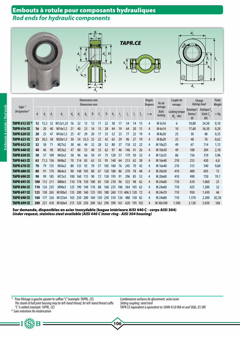
106
S2h2
l7 l4
d5
d2
dk D
BC1
dd1
l3
d4
d3
α
α
IS
B
Sigle 1)
Designation1)
Dimensions mmDimensions mm
DegrésDegrees Vis de
serrageBolts
locking
Couple de serrage:
ChargeRatings load
PoidsWeight
d d1 d
2 d
3 d
4 d
5 d
KB C
1 D h
2l
3l
4l
7S
2≈ α
Locking torque M
A - Nm
Dynamique CDinamyc C
KN
Statique Co
Static Co
KN≈ Kg
TAPR 612 CE 2) 12 15,5 32 M12x1,25 16 32 13 12 11 22 38 17 54 14 15 4 M 5x16 6 10,80 24,50 0,10TAPR 616 CE 16 20 40 M14x1,5 21 40 23 16 13 28 44 19 64 20 15 4 M 6x14 10 17,60 36,50 0,20TAPR 620 CE 20 25 47 M16x1,5 25 47 29 20 17 35 52 23 77 22 19 4 M 8x20 25 30 48 0,35TAPR 625 CE 25 30,5 58 M20x1,5 30 54 35,5 25 22 42 65 29 96 27 19 4 M 8x20 25 48 78 0,62TAPR 632 CE 32 38 71 M27x2 38 66 44 32 28 52 80 37 118 32 22 4 M 10x25 49 67 114 1,15TAPR 640 CE 40 46 90 M33x2 47 80 53 40 33 62 97 46 146 41 26 4 M 10x30 49 100 204 2,18TAPR 650 CE 50 57 109 M42x2 58 96 66 50 41 75 120 57 179 50 32 4 M 12x35 86 156 310 3,96TAPR 663 CE 63 71,5 136 M48x2 70 114 83 63 53 95 140 64 213 62 38 4 M 16x40 210 255 430 6,8TAPR 670 CE 70 79 155 M56x2 80 135 92 70 57 105 160 76 245 70 42 4 M 16x40 210 315 540 9,60TAPR 680 CE 80 91 170 M64x3 90 148 105 80 67 120 180 86 270 78 48 4 M 20x50 410 400 695 13TAPR 690 CE 90 99 185 M72x3 100 160 115 90 72 130 195 91 296 85 52 4 M 20x60 410 490 750 19,1TAPR 695 CE 100 113 211 M80x3 110 178 130 100 85 150 210 96 322 98 62 4 M 24x60 710 610 1.060 25TAPR 696 CE 110 124 235 M90x3 125 190 140 110 88 160 235 106 364 105 62 4 M 24x60 710 655 1.200 32TAPR 697 CE 125 138 265 M100x3 135 200 160 125 103 180 260 113 406.5 120 72 4 M 24x70 710 950 1.430 46TAPR 698 CE 160 177 326 M125x4 165 250 200 160 130 230 310 126 488 150 82 4 M 24x80 710 1.370 2.200 82,50TAPR 699 CE 200 221 418 M160x4 215 320 250 200 162 290 390 161 620 195 102 4 M 30x100 1.500 2.120 3.650 168
Embouts à rotule pour composants hydrauliquesRod ends for hydraulic components
TAPR.CE
1) Pour filetage à gauche ajouter le suffixe “L” (exemple: TAPRL..CE) The shank of ball joint housing may be left-hand thread, for left-hand thread suffix
“L” is added (example: TAPRL..CE)2) Sans entretien No relubrication
Combinaison surfaces de glissement: acier/acierSliding coupling: steel/steelTAPR.CE équivalent à equivalent to: GIHN-K LO INA et and SIQG..ES SKF
Sur demande, disponibles en acier inoxydable (bague intérieure AISI 440 C - corps AISI 304)Under request, stainless steel available (AISI 440 C inner ring - AISI 304 housing)
Emb
outs
à ro
tule
/ Ro
d en
ds
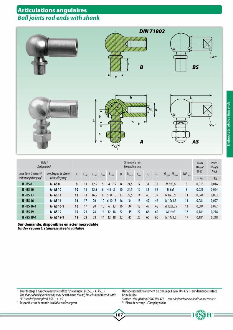
107
M1
h L2
L1
f
e
b
c
d
k
g
SW3)
M2
SW3)
Sigle 1)
Designation1)
Dimensions mmDimensions mm
PoidsWeight
B-BS
PoidsWeight
A-ASavec étrier à ressort2)
with spring clamping2)
avec bague de sûretéwith safety ring
d b ± 0,3
c ± 0,3
e h11
f ± 0,2
g h ± 0,3
k min
L1
L2
M1 (6H)
- M2 (6g)
SW3) h14
≈ Kg ≈ Kg
B - BS 8 A - AS 8 8 11 12,5 5 4 7,5 8 24,5 12 31 32 M 5x0,8 8 0,013 0,014
B - BS 10 A - AS 10 10 11 12,5 6 4,5 8 10 24,5 12 31 32 M 6x1 8 0,021 0,024
B - BS 13 A - AS 13 13 13 16,5 8 5 8 10 13 29,5 14 40 39 M 8x1,25 11 0,044 0,053
B - BS 16 A - AS 16 16 17 20 10 6 10 13 16 34 18 49 46 M 10x1,5 13 0,084 0,097
B - BS 16-1 A - AS 16-1 16 17 20 10 6 13 16 34 18 49 46 M 10x1,75 13 0,084 0,097
B - BS 19 A - AS 19 19 23 28 14 12 18 22 45 22 66 60 M 14x2 17 0,184 0,218
B - BS 19-1 A - AS 19-1 19 23 28 14 12 18 22 45 22 66 60 M 14x1,5 17 0,184 0,218
Articulations angulairesBall joints rod ends with shank
B BS
A AS
1) Pour filetage à gauche ajouter le suffixe “L” (exemple: B-BSL.. - A-ASL..) The shank of ball joint housing may be left-hand thread, for left-hand thread suffix
“L” is added (example: B-BSL.. - A-ASL..)2) Disponible sur demande Available under request
Usinage normal: traitement de zinguage FeZn7 Uni 4721 - sur demande surface brute huiléeSurface : zinc-plating FeZn7 Uni 4721 - raw oiled surface available under request3) Plans de serrage - Clamping plains
Sur demande, disponibles en acier inoxydableUnder request, stainless steel available
DIN 71802
Emb
outs
à ro
tule
/ Ro
d en
ds
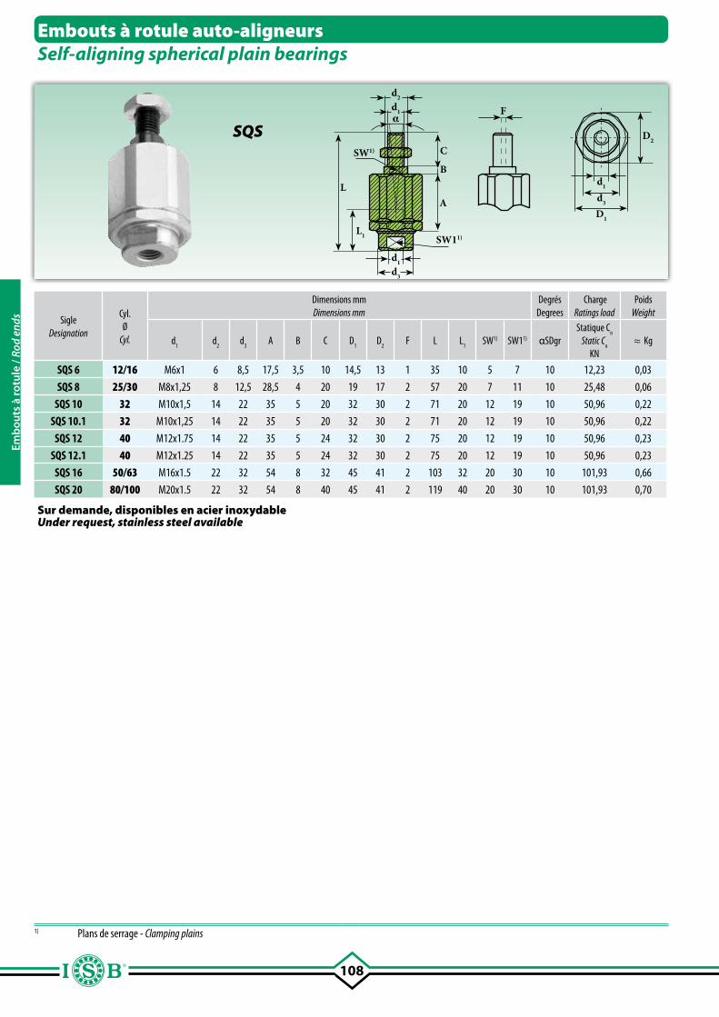
108
C
d2
d1α
SW1)
SW11)
d1
d3
L
L1
A
B
F
d1
D2
d3
D1
SigleDesignation
Cyl.Ø
Cyl.
Dimensions mmDimensions mm
DegrésDegrees
ChargeRatings load
PoidsWeight
d1
d2
d3
A B C D1
D2
F L L1
SW1) SW11) αSDgrStatique C
o
Static Co
KN≈ Kg
SQS 6 12/16 M6x1 6 8,5 17,5 3,5 10 14,5 13 1 35 10 5 7 10 12,23 0,03
SQS 8 25/30 M8x1,25 8 12,5 28,5 4 20 19 17 2 57 20 7 11 10 25,48 0,06
SQS 10 32 M10x1,5 14 22 35 5 20 32 30 2 71 20 12 19 10 50,96 0,22
SQS 10.1 32 M10x1,25 14 22 35 5 20 32 30 2 71 20 12 19 10 50,96 0,22
SQS 12 40 M12x1.75 14 22 35 5 24 32 30 2 75 20 12 19 10 50,96 0,23
SQS 12.1 40 M12x1.25 14 22 35 5 24 32 30 2 75 20 12 19 10 50,96 0,23
SQS 16 50/63 M16x1.5 22 32 54 8 32 45 41 2 103 32 20 30 10 101,93 0,66
SQS 20 80/100 M20x1.5 22 32 54 8 40 45 41 2 119 40 20 30 10 101,93 0,70
Embouts à rotule auto-aligneursSelf-aligning spherical plain bearings
SQS
1) Plans de serrage - Clamping plains
Sur demande, disponibles en acier inoxydableUnder request, stainless steel available
Emb
outs
à ro
tule
/ Ro
d en
ds
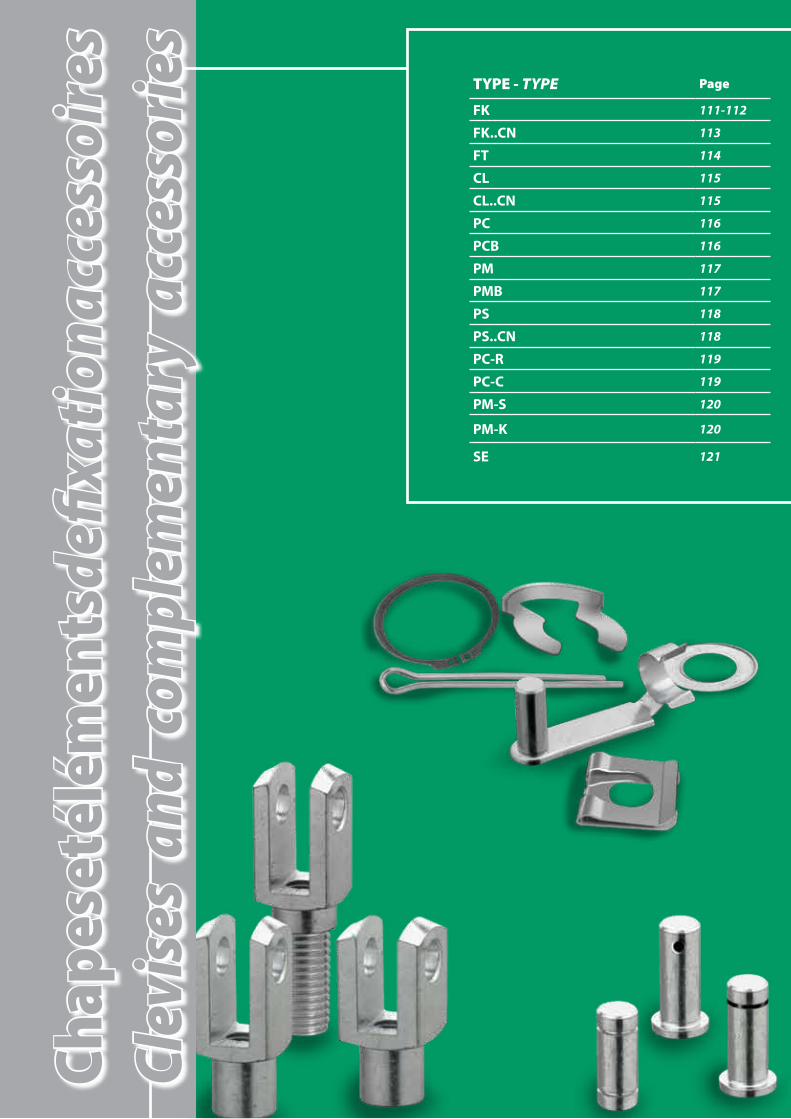
TYPE - TYPE Page
FK 111-112
FK..CN 113
FT 114
CL 115
CL..CN 115
PC 116
PCB 116
PM 117
PMB 117
PS 118
PS..CN 118
PC-R 119
PC-C 119
PM-S 120
PM-K 120
SE 121
Chap
es et
élém
ents
de fix
atio
n acc
esso
ires
Clev
ises
and
com
plem
enta
ry a
cces
sorie
s

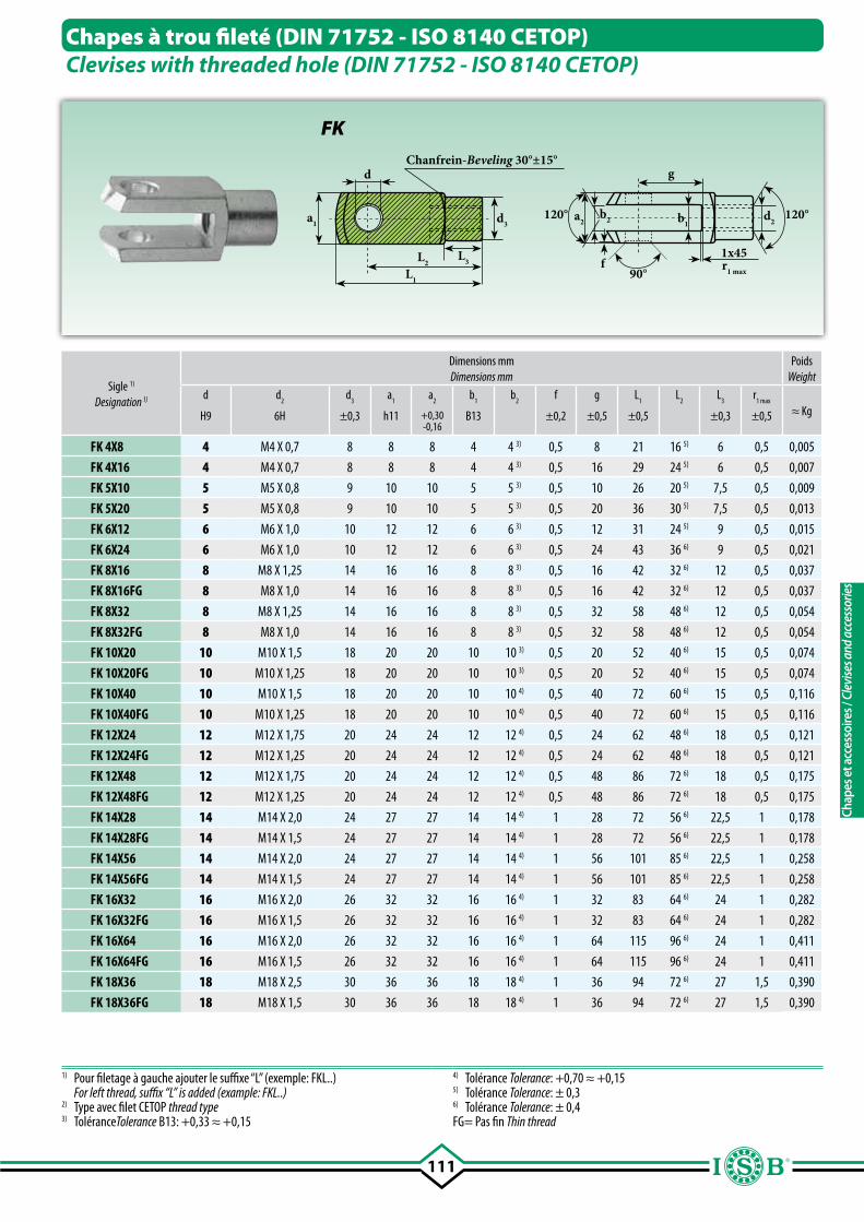
111
L2
d
L1
L3
d3a1
Chanfrein-Beveling 30°±15°
90°
120°120°
g
b2a2 d2b1
r1 max
1x45f
Sigle 1)
Designation 1)
Dimensions mmDimensions mm
PoidsWeight
d d2
d3
a1
a2
b1 b
2f g L
1L
2L
3r
1 max
≈ KgH9 6H ±0,3 h11 +0,30-0,16
B13 ±0,2 ±0,5 ±0,5 ±0,3 ±0,5
FK 4X8 4 M4 X 0,7 8 8 8 4 4 3) 0,5 8 21 16 5) 6 0,5 0,005
FK 4X16 4 M4 X 0,7 8 8 8 4 4 3) 0,5 16 29 24 5) 6 0,5 0,007
FK 5X10 5 M5 X 0,8 9 10 10 5 5 3) 0,5 10 26 20 5) 7,5 0,5 0,009
FK 5X20 5 M5 X 0,8 9 10 10 5 5 3) 0,5 20 36 30 5) 7,5 0,5 0,013
FK 6X12 6 M6 X 1,0 10 12 12 6 6 3) 0,5 12 31 24 5) 9 0,5 0,015
FK 6X24 6 M6 X 1,0 10 12 12 6 6 3) 0,5 24 43 36 6) 9 0,5 0,021
FK 8X16 8 M8 X 1,25 14 16 16 8 8 3) 0,5 16 42 32 6) 12 0,5 0,037
FK 8X16FG 8 M8 X 1,0 14 16 16 8 8 3) 0,5 16 42 32 6) 12 0,5 0,037
FK 8X32 8 M8 X 1,25 14 16 16 8 8 3) 0,5 32 58 48 6) 12 0,5 0,054
FK 8X32FG 8 M8 X 1,0 14 16 16 8 8 3) 0,5 32 58 48 6) 12 0,5 0,054
FK 10X20 10 M10 X 1,5 18 20 20 10 10 3) 0,5 20 52 40 6) 15 0,5 0,074
FK 10X20FG 10 M10 X 1,25 18 20 20 10 10 3) 0,5 20 52 40 6) 15 0,5 0,074
FK 10X40 10 M10 X 1,5 18 20 20 10 10 4) 0,5 40 72 60 6) 15 0,5 0,116
FK 10X40FG 10 M10 X 1,25 18 20 20 10 10 4) 0,5 40 72 60 6) 15 0,5 0,116
FK 12X24 12 M12 X 1,75 20 24 24 12 12 4) 0,5 24 62 48 6) 18 0,5 0,121
FK 12X24FG 12 M12 X 1,25 20 24 24 12 12 4) 0,5 24 62 48 6) 18 0,5 0,121
FK 12X48 12 M12 X 1,75 20 24 24 12 12 4) 0,5 48 86 72 6) 18 0,5 0,175
FK 12X48FG 12 M12 X 1,25 20 24 24 12 12 4) 0,5 48 86 72 6) 18 0,5 0,175
FK 14X28 14 M14 X 2,0 24 27 27 14 14 4) 1 28 72 56 6) 22,5 1 0,178
FK 14X28FG 14 M14 X 1,5 24 27 27 14 14 4) 1 28 72 56 6) 22,5 1 0,178
FK 14X56 14 M14 X 2,0 24 27 27 14 14 4) 1 56 101 85 6) 22,5 1 0,258
FK 14X56FG 14 M14 X 1,5 24 27 27 14 14 4) 1 56 101 85 6) 22,5 1 0,258
FK 16X32 16 M16 X 2,0 26 32 32 16 16 4) 1 32 83 64 6) 24 1 0,282
FK 16X32FG 16 M16 X 1,5 26 32 32 16 16 4) 1 32 83 64 6) 24 1 0,282
FK 16X64 16 M16 X 2,0 26 32 32 16 16 4) 1 64 115 96 6) 24 1 0,411
FK 16X64FG 16 M16 X 1,5 26 32 32 16 16 4) 1 64 115 96 6) 24 1 0,411
FK 18X36 18 M18 X 2,5 30 36 36 18 18 4) 1 36 94 72 6) 27 1,5 0,390
FK 18X36FG 18 M18 X 1,5 30 36 36 18 18 4) 1 36 94 72 6) 27 1,5 0,390
Chapes à trou fileté (DIN 71752 - ISO 8140 CETOP)Clevises with threaded hole (DIN 71752 - ISO 8140 CETOP)
FK
1) Pour filetage à gauche ajouter le suffixe “L” (exemple: FKL..) For left thread, suffix “L” is added (example: FKL..)2) Type avec filet CETOP thread type3) ToléranceTolerance B13: +0,33 ≈ +0,15
4) Tolérance Tolerance: +0,70 ≈ +0,15 5) Tolérance Tolerance: ± 0,36) Tolérance Tolerance: ± 0,4FG= Pas fin Thin thread
Chap
es e
t acc
esso
ires /
Cle
vise
s and
acc
esso
ries
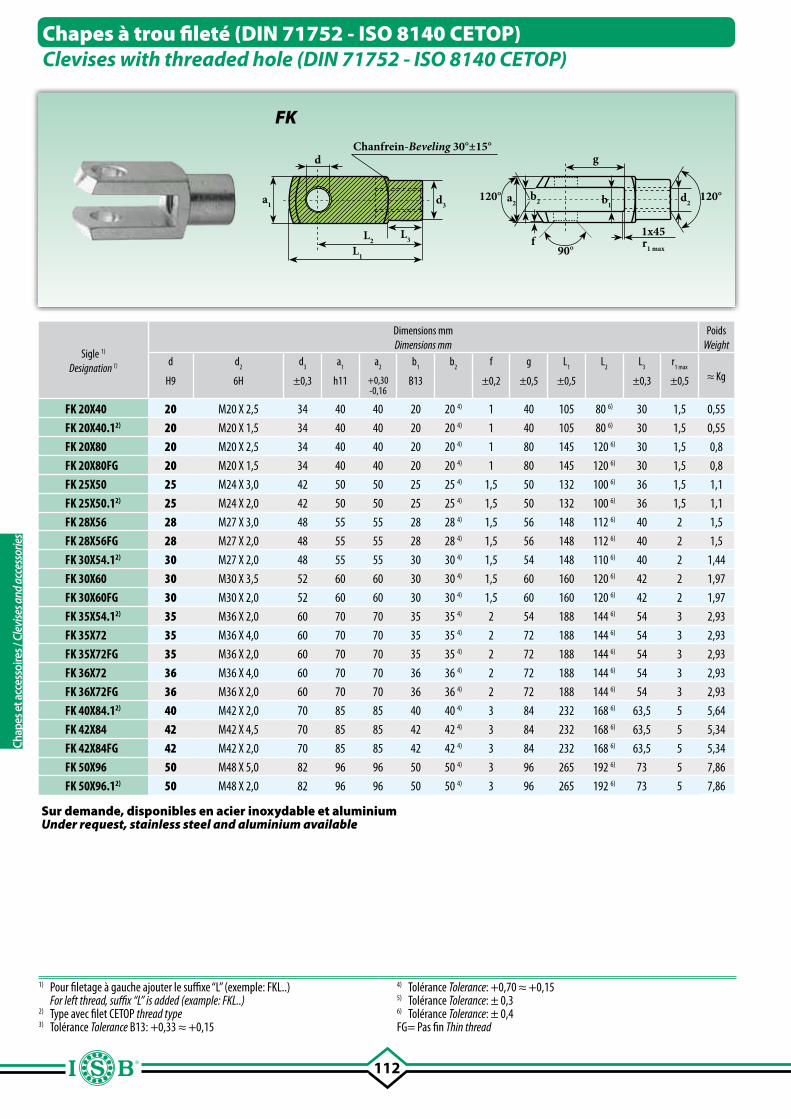
112
Chapes à trou fileté (DIN 71752 - ISO 8140 CETOP)Clevises with threaded hole (DIN 71752 - ISO 8140 CETOP)
Sigle 1)
Designation 1)
Dimensions mmDimensions mm
PoidsWeight
d d2
d3
a1
a2
b1 b
2f g L
1L
2L
3r
1 max
≈ KgH9 6H ±0,3 h11 +0,30-0,16
B13 ±0,2 ±0,5 ±0,5 ±0,3 ±0,5
FK 20X40 20 M20 X 2,5 34 40 40 20 20 4) 1 40 105 80 6) 30 1,5 0,55
FK 20X40.12) 20 M20 X 1,5 34 40 40 20 20 4) 1 40 105 80 6) 30 1,5 0,55
FK 20X80 20 M20 X 2,5 34 40 40 20 20 4) 1 80 145 120 6) 30 1,5 0,8
FK 20X80FG 20 M20 X 1,5 34 40 40 20 20 4) 1 80 145 120 6) 30 1,5 0,8
FK 25X50 25 M24 X 3,0 42 50 50 25 25 4) 1,5 50 132 100 6) 36 1,5 1,1
FK 25X50.12) 25 M24 X 2,0 42 50 50 25 25 4) 1,5 50 132 100 6) 36 1,5 1,1
FK 28X56 28 M27 X 3,0 48 55 55 28 28 4) 1,5 56 148 112 6) 40 2 1,5
FK 28X56FG 28 M27 X 2,0 48 55 55 28 28 4) 1,5 56 148 112 6) 40 2 1,5
FK 30X54.12) 30 M27 X 2,0 48 55 55 30 30 4) 1,5 54 148 110 6) 40 2 1,44
FK 30X60 30 M30 X 3,5 52 60 60 30 30 4) 1,5 60 160 120 6) 42 2 1,97
FK 30X60FG 30 M30 X 2,0 52 60 60 30 30 4) 1,5 60 160 120 6) 42 2 1,97
FK 35X54.12) 35 M36 X 2,0 60 70 70 35 35 4) 2 54 188 144 6) 54 3 2,93
FK 35X72 35 M36 X 4,0 60 70 70 35 35 4) 2 72 188 144 6) 54 3 2,93
FK 35X72FG 35 M36 X 2,0 60 70 70 35 35 4) 2 72 188 144 6) 54 3 2,93
FK 36X72 36 M36 X 4,0 60 70 70 36 36 4) 2 72 188 144 6) 54 3 2,93
FK 36X72FG 36 M36 X 2,0 60 70 70 36 36 4) 2 72 188 144 6) 54 3 2,93
FK 40X84.12) 40 M42 X 2,0 70 85 85 40 40 4) 3 84 232 168 6) 63,5 5 5,64
FK 42X84 42 M42 X 4,5 70 85 85 42 42 4) 3 84 232 168 6) 63,5 5 5,34
FK 42X84FG 42 M42 X 2,0 70 85 85 42 42 4) 3 84 232 168 6) 63,5 5 5,34
FK 50X96 50 M48 X 5,0 82 96 96 50 50 4) 3 96 265 192 6) 73 5 7,86
FK 50X96.12) 50 M48 X 2,0 82 96 96 50 50 4) 3 96 265 192 6) 73 5 7,86
1) Pour filetage à gauche ajouter le suffixe “L” (exemple: FKL..) For left thread, suffix “L” is added (example: FKL..)2) Type avec filet CETOP thread type3) Tolérance Tolerance B13: +0,33 ≈ +0,15
4) Tolérance Tolerance: +0,70 ≈ +0,15 5) Tolérance Tolerance: ± 0,36) Tolérance Tolerance: ± 0,4FG= Pas fin Thin thread
Sur demande, disponibles en acier inoxydable et aluminiumUnder request, stainless steel and aluminium available
L2
d
L1
L3
d3a1
Chanfrein-Beveling 30°±15°
90°
120°120°
g
b2a2 d2b1
r1 max
1x45f
FK
Chap
es e
t acc
esso
ires /
Cle
vise
s and
acc
esso
ries
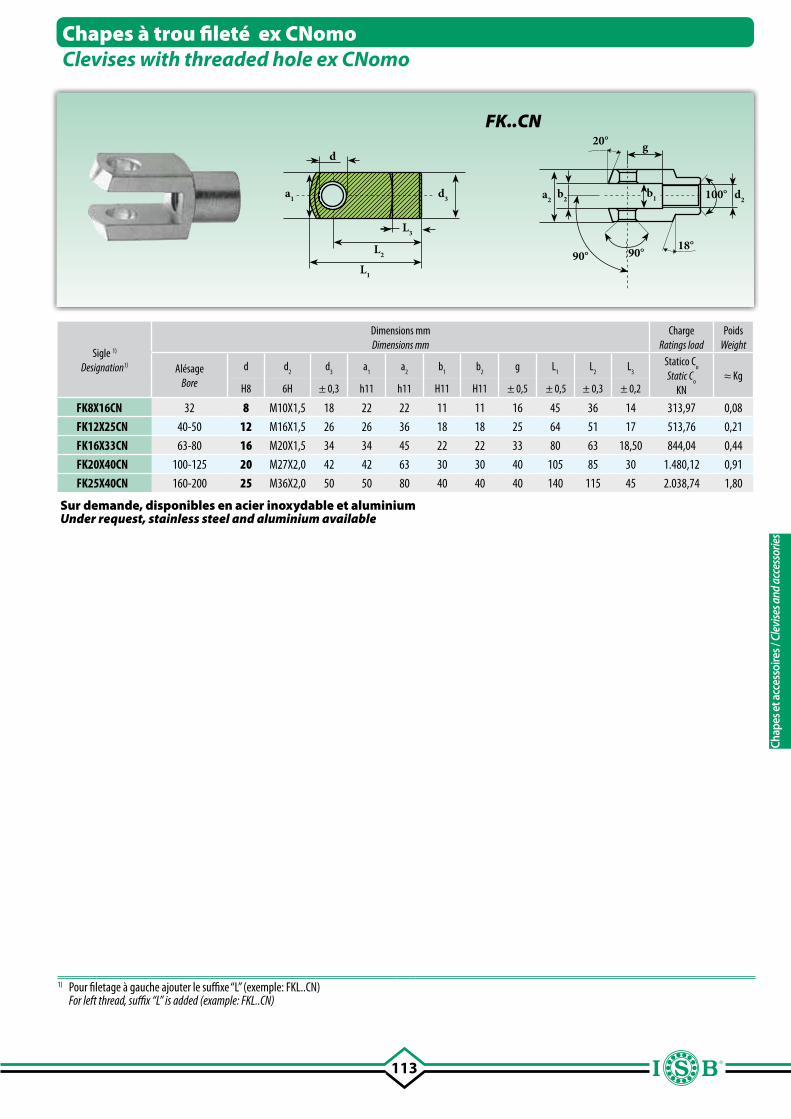
113
18°
a2b2
g20°
90° 90°
100° d2a1 d3
d
L1
L2
L3
b1
Chapes à trou fileté ex CNomoClevises with threaded hole ex CNomo
Sigle 1)
Designation1)
Dimensions mmDimensions mm
ChargeRatings load
PoidsWeight
AlésageBore
d d2
d3 a
1a
2b
1 b
2g L
1 L
2L
3 Statico C
o
Static Co
KN≈ Kg
H8 6H ± 0,3 h11 h11 H11 H11 ± 0,5 ± 0,5 ± 0,3 ± 0,2
FK8X16CN 32 8 M10X1,5 18 22 22 11 11 16 45 36 14 313,97 0,08
FK12X25CN 40-50 12 M16X1,5 26 26 36 18 18 25 64 51 17 513,76 0,21
FK16X33CN 63-80 16 M20X1,5 34 34 45 22 22 33 80 63 18,50 844,04 0,44
FK20X40CN 100-125 20 M27X2,0 42 42 63 30 30 40 105 85 30 1.480,12 0,91
FK25X40CN 160-200 25 M36X2,0 50 50 80 40 40 40 140 115 45 2.038,74 1,80
FK..CN
1) Pour filetage à gauche ajouter le suffixe “L” (exemple: FKL..CN) For left thread, suffix “L” is added (example: FKL..CN)
Sur demande, disponibles en acier inoxydable et aluminiumUnder request, stainless steel and aluminium available
Chap
es e
t acc
esso
ires /
Cle
vise
s and
acc
esso
ries
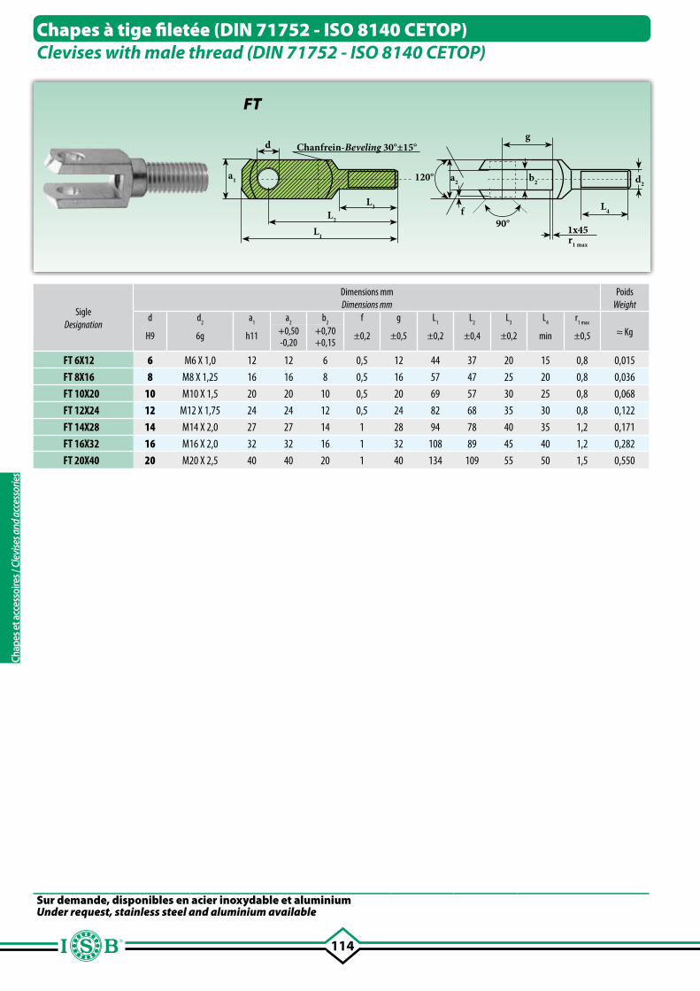
114
Chanfrein-Beveling 30°±15°
L2
L1
L3
d
a1
90°
g
a2 d2
r1 max
1x45
f L4
b2120°
SigleDesignation
Dimensions mmDimensions mm
PoidsWeight
d d2
a1 a
2 b
2f g L
1L
2L
3L
4r
1 max
≈ Kg+0,50 +0,70H9 6g h11 ±0,2 ±0,5 ±0,2 ±0,4 ±0,2 min ±0,5-0,20 +0,15
FT 6X12 6 M6 X 1,0 12 12 6 0,5 12 44 37 20 15 0,8 0,015
FT 8X16 8 M8 X 1,25 16 16 8 0,5 16 57 47 25 20 0,8 0,036
FT 10X20 10 M10 X 1,5 20 20 10 0,5 20 69 57 30 25 0,8 0,068
FT 12X24 12 M12 X 1,75 24 24 12 0,5 24 82 68 35 30 0,8 0,122
FT 14X28 14 M14 X 2,0 27 27 14 1 28 94 78 40 35 1,2 0,171
FT 16X32 16 M16 X 2,0 32 32 16 1 32 108 89 45 40 1,2 0,282
FT 20X40 20 M20 X 2,5 40 40 20 1 40 134 109 55 50 1,5 0,550
Chapes à tige filetée (DIN 71752 - ISO 8140 CETOP)Clevises with male thread (DIN 71752 - ISO 8140 CETOP)
FT
Sur demande, disponibles en acier inoxydable et aluminiumUnder request, stainless steel and aluminium available
Chap
es e
t acc
esso
ires /
Cle
vise
s and
acc
esso
ries
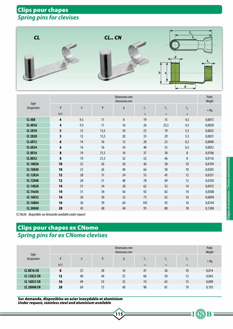
115
CL L2
L1
b a
g
dL3
Clips pour chapesSpring pins for clevises
Sigle Designation
Dimensions mmDimensions mm
PoidsWeight
d a b g L1 L
2L
3
≈ Kgh11 ≈ ≈ ≈
CL 4X8 4 9,5 11 8 19 15 4,5 0,0015
CL 4X16 4 9,5 11 16 26 23,5 4,5 0,0020
CL 5X10 5 12 13,5 10 23 19 5,5 0,0025
CL 5X20 5 12 13,5 20 33 29 5,5 0,0031
CL 6X12 6 14 16 12 28 23 6,5 0,0046
CL 6X24 6 14 16 24 40 35 6,5 0,0052
CL 8X16 8 19 21,5 16 37 30 8 0,0106
CL 8X32 8 19 21,5 32 52 46 8 0,0116
CL 10X20 10 23 26 20 46 38 10 0,0194
CL 10X40 10 23 26 40 66 58 10 0,0205
CL 12X24 12 28 31 24 53 45 12 0,0331
CL 12X48 12 28 31 48 78 69 12 0,0350
CL 14X28 14 31 34 28 62 52 14 0,0472
CL 14x56 14 31 34 56 92 82 14 0,0508
CL 16X32 16 36 39 32 73 62 16 0,0694
CL 16X64 16 36 39 64 103 92 16 0,0744
CL 20X40 20 45 48 40 95 80 18 0,1300
Clips pour chapes ex CNomoSpring pins for ex CNomo clevises
Sigle Designation
Dimensions mmDimensions mm
PoidsWeight
d a b g L1 L
2L
3
≈ Kgh11 ≈ ≈ ≈
CL 8X16 CN 8 25 28 16 41 36 10 0,014
CL 12X25 CN 12 40 44 25 60 50 12 0,043
CL 16X33 CN 16 49 53 33 74 63 15 0,090
CL 20X40 CN 20 69 73 40 98 81 19 0,193
CL.. CN
Sur demande, disponibles en acier inoxydable et aluminiumUnder request, stainless steel and aluminium available
CL18x36 disponible sur demande available under request
Chap
es e
t acc
esso
ires /
Cle
vise
s and
acc
esso
ries
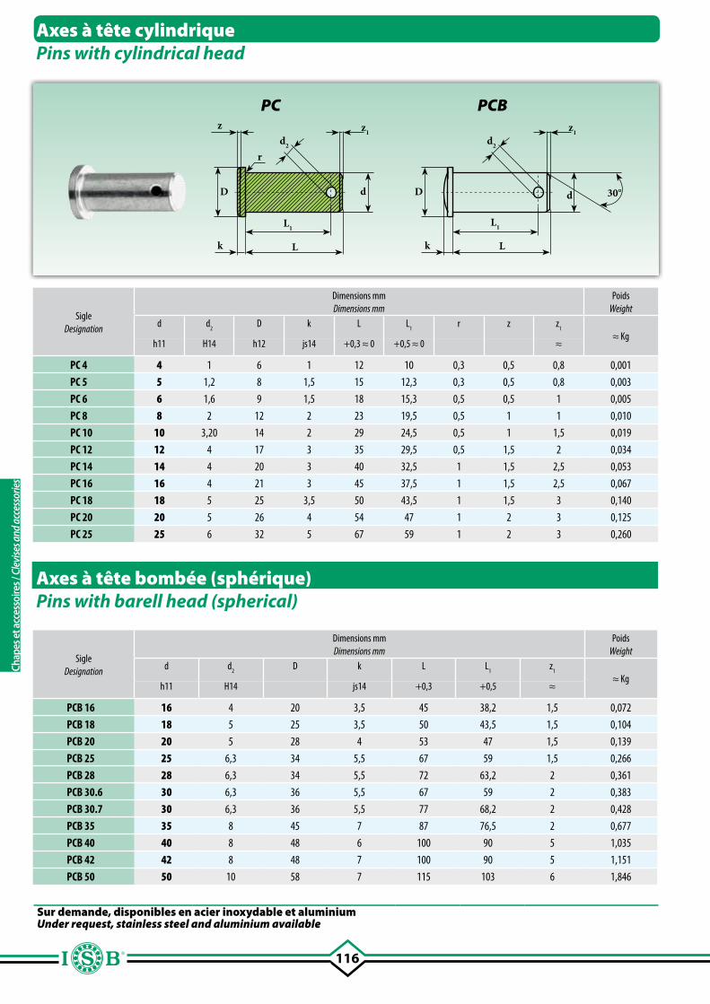
116
r
z
k
D
L
L1
d
z1d2
k
D
L
L1
z1d2
d 30°
Axes à tête cylindriquePins with cylindrical head
Axes à tête bombée (sphérique) Pins with barell head (spherical)
SigleDesignation
Dimensions mmDimensions mm
PoidsWeight
d d2
D k L L1
r z z1
≈ Kgh11 H14 h12 js14 +0,3 ≈ 0 +0,5 ≈ 0 ≈
PC 4 4 1 6 1 12 10 0,3 0,5 0,8 0,001
PC 5 5 1,2 8 1,5 15 12,3 0,3 0,5 0,8 0,003
PC 6 6 1,6 9 1,5 18 15,3 0,5 0,5 1 0,005
PC 8 8 2 12 2 23 19,5 0,5 1 1 0,010
PC 10 10 3,20 14 2 29 24,5 0,5 1 1,5 0,019
PC 12 12 4 17 3 35 29,5 0,5 1,5 2 0,034
PC 14 14 4 20 3 40 32,5 1 1,5 2,5 0,053
PC 16 16 4 21 3 45 37,5 1 1,5 2,5 0,067
PC 18 18 5 25 3,5 50 43,5 1 1,5 3 0,140
PC 20 20 5 26 4 54 47 1 2 3 0,125
PC 25 25 6 32 5 67 59 1 2 3 0,260
SigleDesignation
Dimensions mmDimensions mm
PoidsWeight
d d2
D k L L1
z1
≈ Kgh11 H14 js14 +0,3 +0,5 ≈
PCB 16 16 4 20 3,5 45 38,2 1,5 0,072
PCB 18 18 5 25 3,5 50 43,5 1,5 0,104
PCB 20 20 5 28 4 53 47 1,5 0,139
PCB 25 25 6,3 34 5,5 67 59 1,5 0,266
PCB 28 28 6,3 34 5,5 72 63,2 2 0,361
PCB 30.6 30 6,3 36 5,5 67 59 2 0,383
PCB 30.7 30 6,3 36 5,5 77 68,2 2 0,428
PCB 35 35 8 45 7 87 76,5 2 0,677
PCB 40 40 8 48 6 100 90 5 1,035
PCB 42 42 8 48 7 100 90 5 1,151
PCB 50 50 10 58 7 115 103 6 1,846
PC PCB
Sur demande, disponibles en acier inoxydable et aluminiumUnder request, stainless steel and aluminium available
Chap
es e
t acc
esso
ires /
Cle
vise
s and
acc
esso
ries
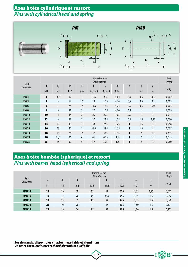
117
rz
k L
L1
m
dD
z1
d1
k L
L1
m
dD
z1
d1
30°
Axes à tête cylindrique et ressortPins with cylindrical head and spring
Axes à tête bombée (sphérique) et ressortPins with barrel head (spherical) and spring
SigleDesignation
Dimensions mmDimensions mm
PoidsWeight
d d1
D k L L1
m r z z1
≈ Kgh11 h11 h12 js14 +0,3 ≈ 0 +0,3 ≈ 0 +0,1 ≈ 0 ≈ ≈
PM 4 4 3,2 6 1 10,5 8,5 0,64 0,3 0,5 0,5 0,002
PM 5 5 4 8 1,5 13 10,5 0,74 0,5 0,5 0,5 0,003
PM 6 6 5 9 1,5 15,5 12,5 0,74 0,5 0,5 0,75 0,004
PM 8 8 6 12 2 20 16,5 0,94 0,5 1 1 0,009
PM 10 10 8 14 2 25 20,5 1,05 0,5 1 1 0,017
PM 12 12 9 17 3 30 24,5 1,15 0,5 1,5 1,25 0,030
PM 14 14 10 19 3 33 27,5 1,25 1 1,5 1,5 0,048
PM 16 16 12 20 3 38,5 32,5 1,35 1 1,5 1,5 0,067
PM 18 18 13 25 3,5 42 36,5 1,35 1 2 1,5 0,895
PM 20 20 17,5 26 4 46 40,5 1,8 1 2 1,5 0,125
PM 25 25 18 32 5 57 50,5 1,8 1 2 1,5 0,260
SigleDesignation
Dimensions mmDimensions mm
PoidsWeight
d d1
D k L L1
m z1
≈ Kgh11 h11 h12 js14 +0,3 +0,3 +0,1 ≈
PMB 14 14 10 20 2,5 33 27,5 1,25 1,25 0,041
PMB 16 16 12 20 3,5 38,5 32,5 1,35 1,5 0,062
PMB 18 18 13 25 3,5 42 36,5 1,35 1,5 0,090
PMB 20 20 17,5 28 4 46 40,5 1,80 1,5 0,121
PMB 25 25 18 34 5,5 57 50,5 1,80 1,5 0,231
PM PMB
Sur demande, disponibles en acier inoxydable et aluminiumUnder request, stainless steel and aluminium available
Chap
es e
t acc
esso
ires /
Cle
vise
s and
acc
esso
ries
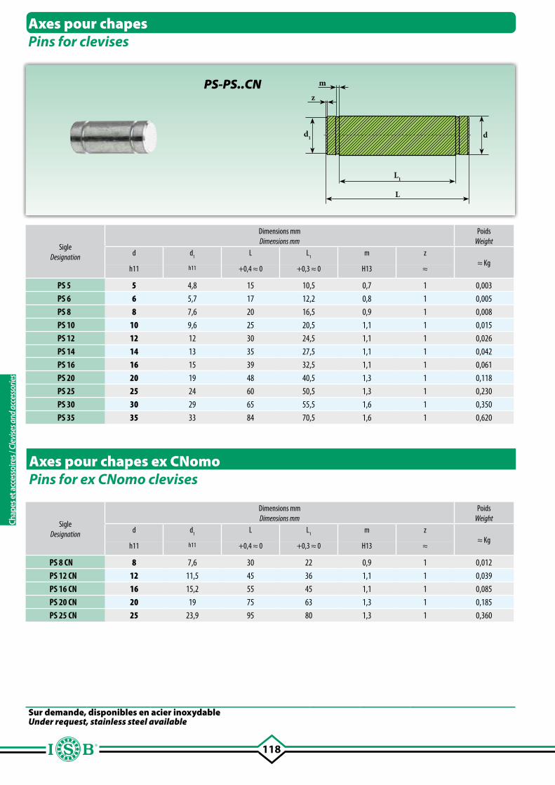
118
z
d1 d
m
L
L1
Axes pour chapesPins for clevises
Axes pour chapes ex CNomoPins for ex CNomo clevises
SigleDesignation
Dimensions mmDimensions mm
PoidsWeight
d d1
L L1
m z≈ Kg
h11 h11 +0,4 ≈ 0 +0,3 ≈ 0 H13 ≈
PS 5 5 4,8 15 10,5 0,7 1 0,003
PS 6 6 5,7 17 12,2 0,8 1 0,005
PS 8 8 7,6 20 16,5 0,9 1 0,008
PS 10 10 9,6 25 20,5 1,1 1 0,015
PS 12 12 12 30 24,5 1,1 1 0,026
PS 14 14 13 35 27,5 1,1 1 0,042
PS 16 16 15 39 32,5 1,1 1 0,061
PS 20 20 19 48 40,5 1,3 1 0,118
PS 25 25 24 60 50,5 1,3 1 0,230
PS 30 30 29 65 55,5 1,6 1 0,350
PS 35 35 33 84 70,5 1,6 1 0,620
SigleDesignation
Dimensions mmDimensions mm
PoidsWeight
d d1
L L1
m z≈ Kg
h11 h11 +0,4 ≈ 0 +0,3 ≈ 0 H13 ≈
PS 8 CN 8 7,6 30 22 0,9 1 0,012
PS 12 CN 12 11,5 45 36 1,1 1 0,039
PS 16 CN 16 15,2 55 45 1,1 1 0,085
PS 20 CN 20 19 75 63 1,3 1 0,185
PS 25 CN 25 23,9 95 80 1,3 1 0,360
PS-PS..CN
Sur demande, disponibles en acier inoxydableUnder request, stainless steel available
Chap
es e
t acc
esso
ires /
Cle
vise
s and
acc
esso
ries
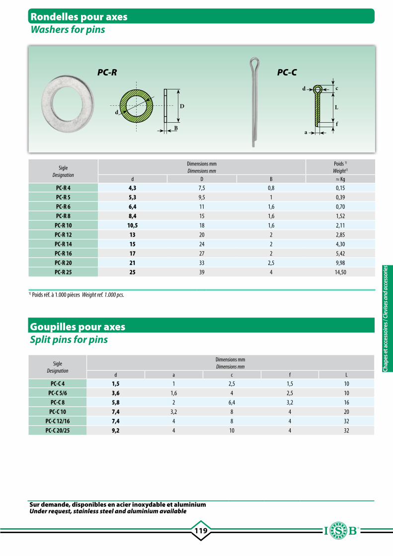
119
Dd
Ba
f
L
cd
SigleDesignation
Dimensions mmDimensions mm
Poids 1)
Weight1) d D B ≈ Kg
PC-R 4 4,3 7,5 0,8 0,15
PC-R 5 5,3 9,5 1 0,39
PC-R 6 6,4 11 1,6 0,70
PC-R 8 8,4 15 1,6 1,52
PC-R 10 10,5 18 1,6 2,11
PC-R 12 13 20 2 2,85
PC-R 14 15 24 2 4,30
PC-R 16 17 27 2 5,42
PC-R 20 21 33 2,5 9,98
PC-R 25 25 39 4 14,50
Rondelles pour axesWashers for pins
Goupilles pour axesSplit pins for pins
SigleDesignation
Dimensions mmDimensions mm
d a c f L
PC-C 4 1,5 1 2,5 1,5 10
PC-C 5/6 3,6 1,6 4 2,5 10
PC-C 8 5,8 2 6,4 3,2 16
PC-C 10 7,4 3,2 8 4 20
PC-C 12/16 7,4 4 8 4 32
PC-C 20/25 9,2 4 10 4 32
PC-R PC-C
1) Poids réf. à 1.000 pièces Weight ref. 1.000 pcs.
Sur demande, disponibles en acier inoxydable et aluminiumUnder request, stainless steel and aluminium available
Chap
es e
t acc
esso
ires /
Cle
vise
s and
acc
esso
ries
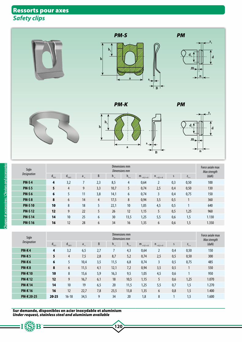
120
h
h1
a s
B
d1
z1
m
n
d
hh1
as
B
d1
z1
m
n
d
SigleDesignation
Dimensions mmDimensions mm
Force axiale max Max strength
(daN)d h11
d1 h11
a ≈
B h ≈
h1 ≈
m + 0,1 ≈ 0
n + 0,3 ≈ 0
s z1 ≈
PM-S 4 4 3,2 7 2,3 8,5 4 0,64 2 0,3 0,50 100
PM-S 5 5 4 9 3,3 10,7 5 0,74 2,5 0,4 0,50 130
PM-S 6 6 5 11 3,8 14,1 6 0,74 3 0,4 0,75 150
PM-S 8 8 6 14 4 17,5 8 0,94 3,5 0,5 1 360
PM-S 10 10 8 18 5 22,1 10 1,05 4,5 0,5 1 640
PM-S 12 12 9 22 5 26 12 1,15 5 0,5 1,25 960
PM-S 14 14 10 25 6 30 13,5 1,25 5,5 0,6 1,5 1.130
PM-S 16 16 12 28 6 34 16 1,35 6 0,6 1,5 1.350
Ressorts pour axesSafety clips
PM-S PM
PM-K PM
Sur demande, disponibles en acier inoxydable et aluminiumUnder request, stainless steel and aluminium available
SigleDesignation
Dimensions mmDimensions mm
Force axiale max Max strength
(daN)d h11
d1 h11
a ≈
B h ≈
h1 ≈
m + 0,1 ≈ 0
n + 0,3 ≈ 0
s z1 ≈
PM-K 4 4 3,2 6,5 2,7 7 4,3 0,64 2 0,4 0,50 150
PM-K 5 5 4 7,5 2,8 8,7 5,2 0,74 2,5 0,5 0,50 300
PM-K 6 6 5 10,4 3,5 11,5 6,8 0,74 3 0,5 0,75 485
PM-K 8 8 6 11,5 4,1 12,1 7,2 0,94 3,5 0,5 1 550
PM-K 10 10 8 15,6 5,9 16,3 9,5 1,05 4,5 0,6 1 950
PM-K 12 12 9 16,7 6,1 18 10,5 1,15 5 0,6 1,25 1.070
PM-K 14 14 10 19 6,5 20 11,5 1,25 5,5 0,7 1,5 1.270
PM-K 16 16 12 22,7 7,8 23,5 13,8 1,35 6 0,8 1,5 1.400
PM-K 20-25 20-25 16-18 34,5 9 34 20 1,8 8 1 1,5 1.600
Chap
es e
t acc
esso
ires /
Cle
vise
s and
acc
esso
ries
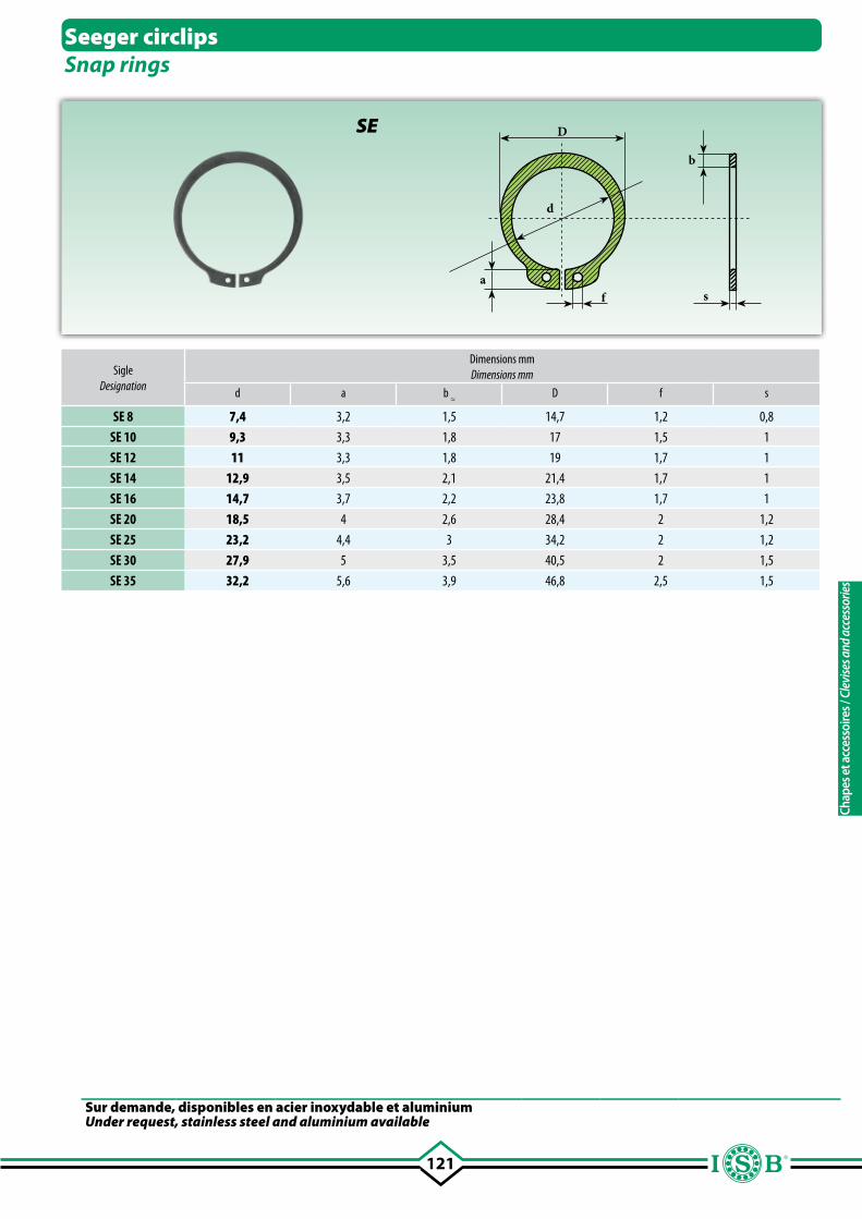
121
Sur demande, disponibles en acier inoxydable et aluminiumUnder request, stainless steel and aluminium available
D
sfa
d
b
Seeger circlipsSnap rings
SigleDesignation
Dimensions mmDimensions mm
d a b ≈
D f s
SE 8 7,4 3,2 1,5 14,7 1,2 0,8
SE 10 9,3 3,3 1,8 17 1,5 1
SE 12 11 3,3 1,8 19 1,7 1
SE 14 12,9 3,5 2,1 21,4 1,7 1
SE 16 14,7 3,7 2,2 23,8 1,7 1
SE 20 18,5 4 2,6 28,4 2 1,2
SE 25 23,2 4,4 3 34,2 2 1,2
SE 30 27,9 5 3,5 40,5 2 1,5
SE 35 32,2 5,6 3,9 46,8 2,5 1,5
SE
Chap
es e
t acc
esso
ires /
Cle
vise
s and
acc
esso
ries
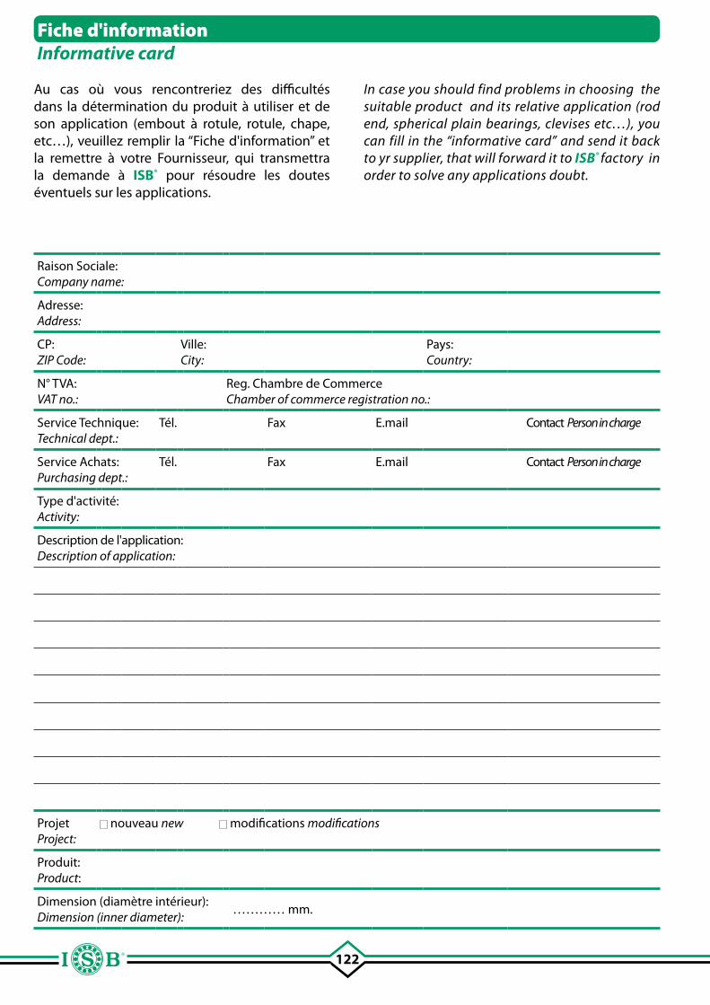
122
Raison Sociale:Company name:
Adresse:Address:
CP:ZIP Code:
Ville:City:
Pays:Country:
N° TVA: VAT no.:
Reg. Chambre de CommerceChamber of commerce registration no.:
Service Technique:Technical dept.:
Tél. Fax E.mail Contact Person in charge
Service Achats:Purchasing dept.:
Tél. Fax E.mail Contact Person in charge
Type d'activité:Activity:
Description de l'application:Description of application:
Projet Project:
nouveau new modifications modifications
Produit: Product:
Dimension (diamètre intérieur):Dimension (inner diameter):
………… mm.
Fiche d'informationInformative card
Au cas où vous rencontreriez des difficultés dans la détermination du produit à utiliser et de son application (embout à rotule, rotule, chape, etc…), veuillez remplir la “Fiche d'information” et la remettre à votre Fournisseur, qui transmettra la demande à ISB® pour résoudre les doutes éventuels sur les applications.
In case you should find problems in choosing the suitable product and its relative application (rod end, spherical plain bearings, clevises etc…), you can fill in the “informative card” and send it back to yr supplier, that will forward it to ISB® factory in order to solve any applications doubt.
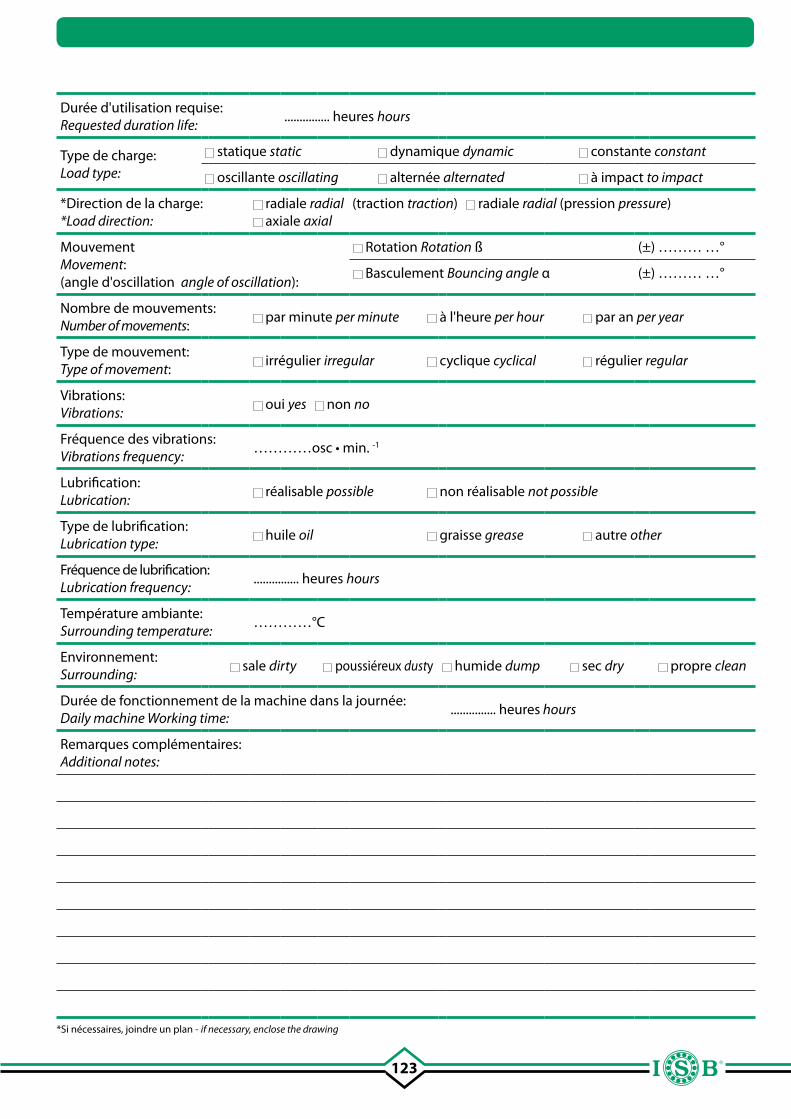
123
Durée d'utilisation requise:Requested duration life:
............... heures hours
Type de charge:Load type:
statique static dynamique dynamic constante constant
oscillante oscillating alternée alternated à impact to impact
*Direction de la charge:*Load direction:
radiale radial (traction traction) radiale radial (pression pressure) axiale axial
Mouvement Movement:(angle d'oscillation angle of oscillation):
Rotation Rotation ß (±) ……… …°
Basculement Bouncing angle α (±) ……… …°
Nombre de mouvements:Number of movements:
par minute per minute à l'heure per hour par an per year
Type de mouvement: Type of movement:
irrégulier irregular cyclique cyclical régulier regular
Vibrations:Vibrations:
oui yes non no
Fréquence des vibrations:Vibrations frequency:
…………osc • min. -1
Lubrification:Lubrication:
réalisable possible non réalisable not possible
Type de lubrification:Lubrication type:
huile oil graisse grease autre other
Fréquence de lubrification:Lubrication frequency:
............... heures hours
Température ambiante:Surrounding temperature:
…………°C
Environnement:Surrounding:
sale dirty poussiéreux dusty humide dump sec dry propre clean
Durée de fonctionnement de la machine dans la journée:Daily machine Working time:
............... heures hours
Remarques complémentaires:Additional notes:
*Si nécessaires, joindre un plan - if necessary, enclose the drawing

RemarquesNotes
RemarquesNotes
RemarquesNotes
©Copyright ISB®
La reproduction même partielle du contenu de ce Catalogue Technique est interdite.Nous n'acceptons aucune responsabilité p o u r l e s e r r e u r s o u o m i s s i o n s . L e s mesures sont fournies à titre indicatif.Marque enregistrée Italie-EU.
T h e r e p r o d u c t i o n , e v e n p a r t i a l , o f t h e c o n t a i n e d c o n c e r n i n g t h i s Te c h n i c a l C a t a l o g u e , i s f o r b i d d e n . L i a b i l i t y f o r p o s s i b l e e r r o r s a n d / o r o m i s s i o n s a r e n o t a c c e p t e d . S i z e s a r e n o t b i n d i n g .TM Registered in Italy-EU.
PALIERS A ROTULE • TÊTES ARTICULÉES • CHAPES SPHERICAL PLAIN BEARINGS • ROD ENDS • CLEVISES
1.7.12 ©Copyright ISB ®


![arXiv:math/0601012v3 [math.QA] 5 Aug 2006 · arXiv:math/0601012v3 [math.QA] 5 Aug 2006 Frobenius-Schur Indicators and Exponents of Spherical Categories Siu-Hung Ng1 Department of](https://img.pdfslide.fr/doc/110x75/5e9e23c81ecd3f5ea83d87ad/arxivmath0601012v3-mathqa-5-aug-2006-arxivmath0601012v3-mathqa-5-aug-2006.jpg)