Embed Size (px)
Citation preview

ITS-ExIECEx/ATEX QUALIFIED HAZARDOUS ZONE CONNECTORS
I E C / E N 6 0 0 7 9 - 0 • I E C / E N 6 0 0 7 9 - 1 IEC/EN 60079-31 • IEC/EN 60079-7 (PANEL MOUNT)
SERIES 927-072
INTERCONNECT SOLUTIONS
MISSION-CRITICAL
MARCH 2019

2 © 2019 Glenair, Inc • 1211 Air Way, Glendale, CA 91201 • 818-247-6000 • www.glenair.com • U.S. CAGE code 06324
Over 40 power and signal contact arrangements
Full support for common armored and unarmored cable types
MIL-DTL-5015 crimp contact derivative solution
Locking set screw equipped coupling nut and protective safety covers
Extended shell labyrinth cooling zone and potting chamber features
Mechanical cable clamp, basket weave, and Ex d cable gland accessories
IP68 water, vapor, moisture and dust protection in mated condition
ITS-Ex IECEx/ATEX Qualified Hazardous/Explosive Zone Connectors
SERIES 927-072
Glenair is a qualified manufacturer of connectors for potential explosive zone use, built IAW IECEx/ATEX standards. The connectors may be used in application areas where
flammable gases and vapors are present as a normal condition of operation (group IIC) and with temperature classes T6 and T5, zones 1 and 2; and for applications where potentially flammable dust is present as a normal condition of operation (group IIIC) and with tempera-ture classes T80°C and T95°C in zone 21 and 22. The connector series design is optimized for fast and easy crimp-contact wire termination with ample wiring space in the cable housing and accessory hardware. Glenair Series ITS-Ex complies with the following standards:
• EN 60079-0 : 2012, “Explosive Atmospheres - Part 0: Equipment - General Requirements”.• EN 60079-1: 2014, “Explosive Atmospheres - Part 1: Equipment protection by
flameproof enclosures ‘d’ ”.• EN 60079-14: 2014, “Explosive Atmospheres - Part 14: Electrical Installations Design,
Selection and Erection.• EN 60079-31: 2014, “Explosive Atmospheres - Part 31: Equipment Dust Ignition
Protection by Enclosure ‘t’ “.• IEC 60079-0: 2011, “Explosive Atmospheres - Part 0: Equipment - General Requirements”.• IEC 60079-1: 2014, “Explosive Atmospheres - Part 1: Equipment Protection by
Flameproof Enclosures ‘d’ “.• IEC 60079-14: 2013, “Explosive Atmospheres - Part 14: Electrical Installations Design,
Selection and Erection.• IEC 60079-31: 2013, “Explosive Atmospheres - Part 31: Equipment Dust Ignition
Protection by Enclosure ‘t’ “.• For panel mount complies also with: EN/IEC 60079-7: 2015, “Explosive Atmospheres -
Part 7: Equipment protection by increased safety ‘e’ ”.
3© 2019 Glenair, Inc • 1211 Air Way, Glendale, CA 91201 • 818-247-6000 • www.glenair.com • U.S. CAGE code 06324 • Series 927-072 ITS-ExDimensions in millimeters are subject to change without notice.
General Information and Series Specifications Page 4
ITS-Ex Plugs Page 36
ITS-Ex Fixed In-Line Receptacles Page 44
ITS-Ex In-Line Receptacles Page 52
ITS-Ex Panel Mount Fixed Receptacles Page 60
Contacts, Tools and Accessories Page 62
SERIES 927-072ITS-Ex Hazardous Zone ConnectorsTable of Contents
4 © 2019 Glenair, Inc • 1211 Air Way, Glendale, CA 91201 • 818-247-6000 • www.glenair.com • U.S. CAGE code 06324 • Series 927-072 ITS-ExDimensions in millimeters are subject to change without notice.
SERIES 927-072ITS-Ex Hazardous Zone ConnectorsZone and category designations
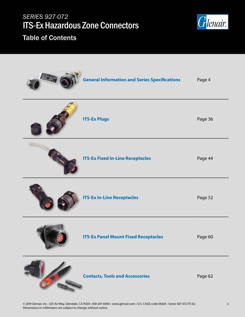
Explosion Triangle
ATEX EXPLOSIVE ZONES AND CATEGORIES
Glenair Series 927-072 ITS-Ex Hazardous Zone Connectors prevent explosions by eliminating the heat component in the explosion triangle. This is accomplished by preventing an ignition source, such as a flame or spark, from migrating through the cable or connector into a defined hazardous zone such as might be found in a pet-rochemical refinery or land/offshore drilling system. Hazardous zones are defined by frequency of presence of explosive gas or dust.
In the ATEX 1999/92/EC directive, hazardous areas are divided into three defined zones: 0, 1, and 2. These zones are designations used to describe the likelihood that explosive mixtures of fuel and oxygen exist during normal conditions of facility operation.
Constant danger Category 1 equipment
Category 2 equipment
Category 3 equipment
Potential danger
Minor danger
OPERATOR
MANUFACTURER
Zone: 2 or 22
Zone: 1 or 21
Zone: 0 or 20
Zone: 2
or 22
Zone: 1 o
r 21
Explosive area zone classifications are used by the operator to distinguish be-tween explosive areas and their relative levels of risk. Operators use the triangular EX mark to indicate compliance with IECEx/ATEX requirements.
Manufacturers however use different classifications to describe where their products may be used.
The two systems generally conform in meaning but the words and symbols change.
Zone 0 (20) Zone 1 (21) Zone 2 (22)
Area in which an explosive gas (dust) atmosphere is
present continuously or for long periods or frequently.
Area in which an explosive gas (dust) atmosphere is likely to occur in normal operation occasionally.
Area in which an explosive gas (dust) atmosphere is likely to occur in normal operation but, if it does occur, will persist for a
short period only.
Hazardous Zone Fuel Types
Gas, vapor and mists: methane, butane, ethylene, hydrogen, acetylene
Dust: aluminum, sulfur, zinc grain, coal, sugar, epoxy resin
Purpose of explosion zone connectors and glands
5© 2019 Glenair, Inc • 1211 Air Way, Glendale, CA 91201 • 818-247-6000 • www.glenair.com • U.S. CAGE code 06324 • Series 927-072 ITS-ExDimensions in millimeters are subject to change without notice.
SERIES 927-072ITS-Ex Hazardous Zone ConnectorsZone and category designations
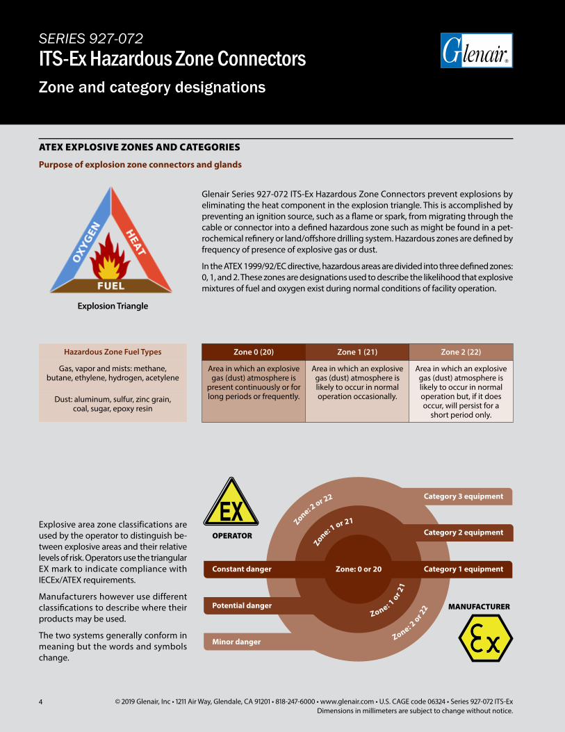
Glenair Series 927-072 ITS-Ex Hazardous Zone Connectors are IAW qualified for class T6 or class T5.The equipment is certified only for use in temperature class T6 with ambient tem-perature between -40°C to +40°C max or the equipment is certified only for use in temperature class T5 with ambient tem-perature between -40°C to +55°C max.The equipment should not be used in an explosive environment outside of this range.A connector with a temperature class of T6 covers from T6 to T1 (but the ambi-ent temperature must be from -40°C to +40°C max).A connector with a temperature class of T5 covers from T5 to T1 (but the ambi-ent temperature must be from -40°C to +55°C max).
Temperature ClassPermissible surface temperatures of the electrical equipment
Ignition temperature of the combustible gases
T1 450 °C > 450 °C
T2 300 °C 300 - 450 °C
T3 200 °C 200 - 300 °C
T4 135 °C 135 - 200 °C
T5 100 °C 100 - 135 °C
T6 85 °C 85 - 100 °C
Group II Gases
IIAAcetone, ethyl alcohol, ammonia, gasoline, butane, hexane,
ethanol, natural gas, methanol, propane
IIB Acetaldehyde, propane, ethylene
IICHydrogen, gas mixture containing more than 25% hydrogen,
acetylene, carbon disulphide
Group III Dust
IIIA Fibers
IIIB Non-conductive dust
IIIC Conductive dust
TEMPERATURE CLASSES
Glenair Connectors 927-072 are quali-fied for Group IIA, IIB, IIC and for Group IIIA, IIIB, IIIC, Category 2 and Category 3.
A connector qualified for Group IIC cover from IIC to IIA.
A connector qualified for Group IIIC cover from IIIC to IIIA.
GROUP II is for explosive GASES for surfaces industries.
GROUP III is for explosive DUST for sur-faces industries.
Category 2 Category 3
Place where explosive atmosphere is likely to occur.Provides the protection level in case of failure of the connector/equipment.
Place where explosive atmosphere are unlikely to occur, or if they do occur not frequently and only for a short period of time.Provides the requisite level of protection during normal operation.

6 © 2019 Glenair, Inc • 1211 Air Way, Glendale, CA 91201 • 818-247-6000 • www.glenair.com • U.S. CAGE code 06324 • Series 927-072 ITS-ExDimensions in millimeters are subject to change without notice.
SERIES 927-072ITS-Ex Hazardous Zone ConnectorsZone and category designations
ATEX Group II
EPL according to IEC/EN 60079-0
Gas Dust
Category 1 Ga Da
Category 2 Gb Db
Category 3 Gc Dc
Atmosphere Zone EPL ATEX Category
Gas
0 Ga 1G
1 Gb or Ga 2G or 1G
2 Gc or Gb or Ga 3G or 2G or 1G
Dust
20 Da 1D
21 Db or Da 2D or 1D
22 Dc or Db or Da 3D or 2D or 1D
The relation between the ATEX 1999/92/EC and the IEC is indicated below: in the Zone 0 you could mount an equipment Ga or 1G (according to 94/9/EC ATEX).
ATEX 2014/34/EU directive classifies the equipment into categories 1, 2, 3 (Group II), based on protection level.
Standard EN/IEC 60079-0 introduces EPL (Equipment Protection Level).
Automotive refuelling or petrol stations Oil & gas extraction Oil refineries Gas pipelines and distribution Chemical processing plants Aircraft refuelling and hangars Transportation Pharmaceuticals Food processing Metal surface grinding Sugar refineries Grain handling and storage Coal mining
IEC AND ATEX
RANGE OF APPLICATIONS
7© 2019 Glenair, Inc • 1211 Air Way, Glendale, CA 91201 • 818-247-6000 • www.glenair.com • U.S. CAGE code 06324 • Series 927-072 ITS-ExDimensions in millimeters are subject to change without notice.
SERIES 927-072ITS-Ex Hazardous Zone ConnectorsITS-Ex Series labeling and materials
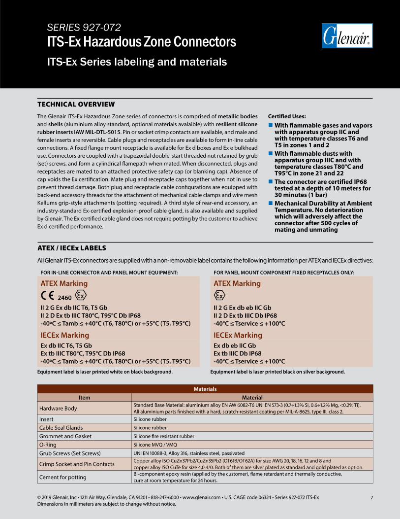
All Glenair ITS-Ex connectors are supplied with a non-removable label contains the following information per ATEX and IECEx directives:
ATEX / IECEx LABELS
MaterialsItem Material
Hardware Body Standard Base Material: aluminium alloy EN AW 6082-T6 UNI EN 573-3 (0.7÷1.3% Si, 0.6÷1.2% Mg, <0.2% Ti). All aluminium parts finished with a hard, scratch-resistant coating per MIL-A-8625, type III, class 2.
Insert Silicone rubber
Cable Seal Glands Silicone rubber
Grommet and Gasket Silicone fire resistant rubber
O-Ring Silicone MVQ / VMQ
Grub Screws (Set Screws) UNI EN 10088-3, Alloy 316, stainless steel, passivated
Crimp Socket and Pin Contacts Copper alloy ISO CuZn37Pb2/CuZn35Pb2 (OT61B/OT62A) for size AWG 20, 18, 16, 12 and 8 and copper alloy ISO CuTe for size 4,0 4/0. Both of them are silver plated as standard and gold plated as option.
Cement for potting Bi-component epoxy resin (applied by the customer), flame retardant and thermally conductive, cure at room temperature for 24 hours.
TECHNICAL OVERVIEW
The Glenair ITS-Ex Hazardous Zone series of connectors is comprised of metallic bodies and shells (aluminium alloy standard, optional materials avalaible) with resilient silicone rubber inserts IAW MIL-DTL-5015. Pin or socket crimp contacts are available, and male and female inserts are reversible. Cable plugs and receptacles are available to form in-line cable connections. A fixed flange mount receptacle is available for Ex d boxes and Ex e bulkhead use. Connectors are coupled with a trapezoidal double-start threaded nut retained by grub (set) screws, and form a cylindrical flamepath when mated. When disconnected, plugs and receptacles are mated to an attached protective safety cap (or blanking cap). Absence of cap voids the Ex certification. Mate plug and receptacle caps together when not in use to prevent thread damage. Both plug and receptacle cable configurations are equipped with back-end accessory threads for the attachment of mechanical cable clamps and wire mesh Kellums grip-style attachments (potting required). A third style of rear-end accessory, an industry-standard Ex-certified explosion-proof cable gland, is also available and supplied by Glenair. The Ex certified cable gland does not require potting by the customer to achieve Ex d certified performance.
Certified Uses:
With flammable gases and vapors with apparatus group IIC and with temperature classes T6 and T5 in zones 1 and 2With flammable dusts with apparatus group IIIC and with temperature classes T80°C and T95°C in zone 21 and 22 The connector are certified IP68 tested at a depth of 10 meters for 30 minutes (1 bar)Mechanical Durability at Ambient Temperature. No deterioration which will adversely affect the connector after 500 cycles of mating and unmating
FOR IN-LINE CONNECTOR AND PANEL MOUNT EQUIPMENT:
ATEX Marking
2460II 2 G Ex db IIC T6, T5 GbII 2 D Ex tb IIIC T80°C, T95°C Db IP68-40ºC ≤ Tamb ≤ +40°C (T6, T80°C) or +55°C (T5, T95°C)
IECEx MarkingEx db IIC T6, T5 GbEx tb IIIC T80°C, T95°C Db IP68-40ºC ≤ Tamb ≤ +40°C (T6, T80°C) or +55°C (T5, T95°C)
FOR PANEL MOUNT COMPONENT FIXED RECEPTACLES ONLY:
ATEX Marking
II 2 G Ex db eb IIC GbII 2 D Ex tb IIIC Db IP68-40°C ≤ Tservice ≤ +100°C
IECEx MarkingEx db eb IIC GbEx tb IIIC Db IP68-40°C ≤ Tservice ≤ +100°C
Equipment label is laser printed white on black background. Equipment label is laser printed black on silver background.
8 © 2019 Glenair, Inc • 1211 Air Way, Glendale, CA 91201 • 818-247-6000 • www.glenair.com • U.S. CAGE code 06324 • Series 927-072 ITS-ExDimensions in millimeters are subject to change without notice.
SERIES 927-072ITS-Ex Hazardous Zone ConnectorsConnector configurations
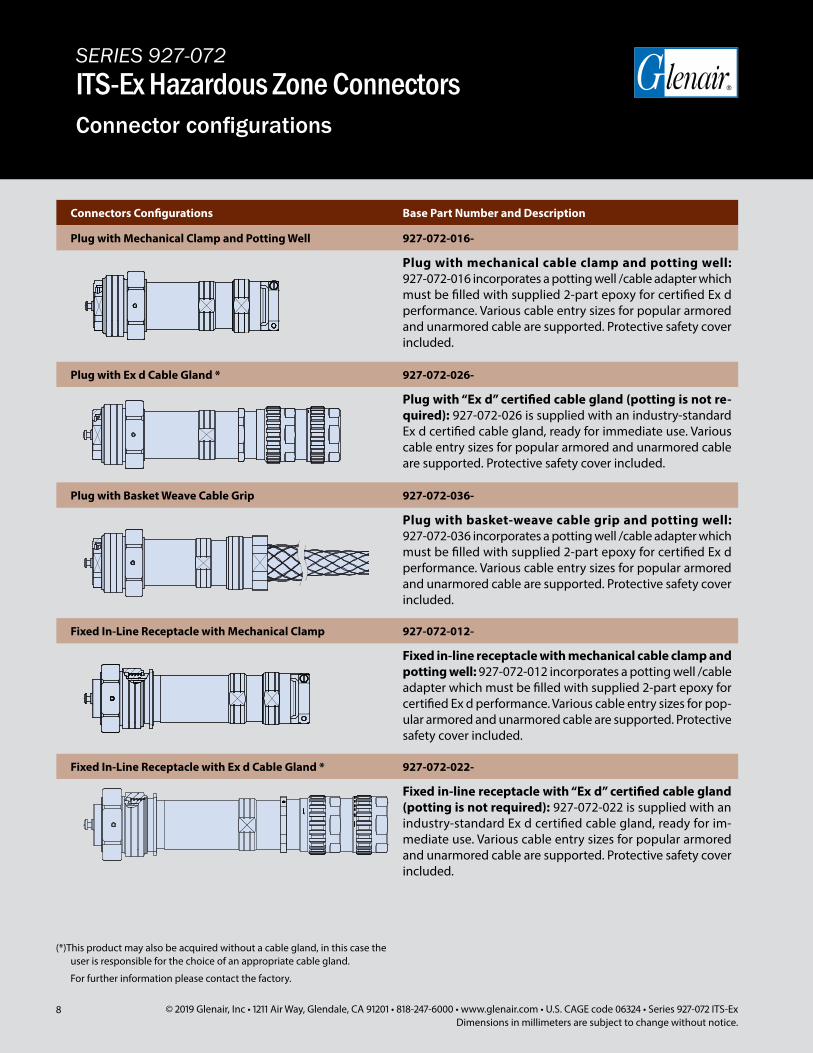
Connectors Configurations Base Part Number and Description
Plug with Mechanical Clamp and Potting Well 927-072-016-
Plug with mechanical cable clamp and potting well: 927-072-016 incorporates a potting well /cable adapter which must be filled with supplied 2-part epoxy for certified Ex d performance. Various cable entry sizes for popular armored and unarmored cable are supported. Protective safety cover included.
Plug with Ex d Cable Gland * 927-072-026-
Plug with “Ex d” certified cable gland (potting is not re-quired): 927-072-026 is supplied with an industry-standard Ex d certified cable gland, ready for immediate use. Various cable entry sizes for popular armored and unarmored cable are supported. Protective safety cover included.
Plug with Basket Weave Cable Grip 927-072-036-
Plug with basket-weave cable grip and potting well: 927-072-036 incorporates a potting well /cable adapter which must be filled with supplied 2-part epoxy for certified Ex d performance. Various cable entry sizes for popular armored and unarmored cable are supported. Protective safety cover included.
Fixed In-Line Receptacle with Mechanical Clamp 927-072-012-
Fixed in-line receptacle with mechanical cable clamp and potting well: 927-072-012 incorporates a potting well /cable adapter which must be filled with supplied 2-part epoxy for certified Ex d performance. Various cable entry sizes for pop-ular armored and unarmored cable are supported. Protective safety cover included.
Fixed In-Line Receptacle with Ex d Cable Gland * 927-072-022-
Fixed in-line receptacle with “Ex d” certified cable gland (potting is not required): 927-072-022 is supplied with an industry-standard Ex d certified cable gland, ready for im-mediate use. Various cable entry sizes for popular armored and unarmored cable are supported. Protective safety cover included.
(*)This product may also be acquired without a cable gland, in this case the user is responsible for the choice of an appropriate cable gland.
For further information please contact the factory.
9© 2019 Glenair, Inc • 1211 Air Way, Glendale, CA 91201 • 818-247-6000 • www.glenair.com • U.S. CAGE code 06324 • Series 927-072 ITS-ExDimensions in millimeters are subject to change without notice.
SERIES 927-072ITS-Ex Hazardous Zone ConnectorsConnector configurations
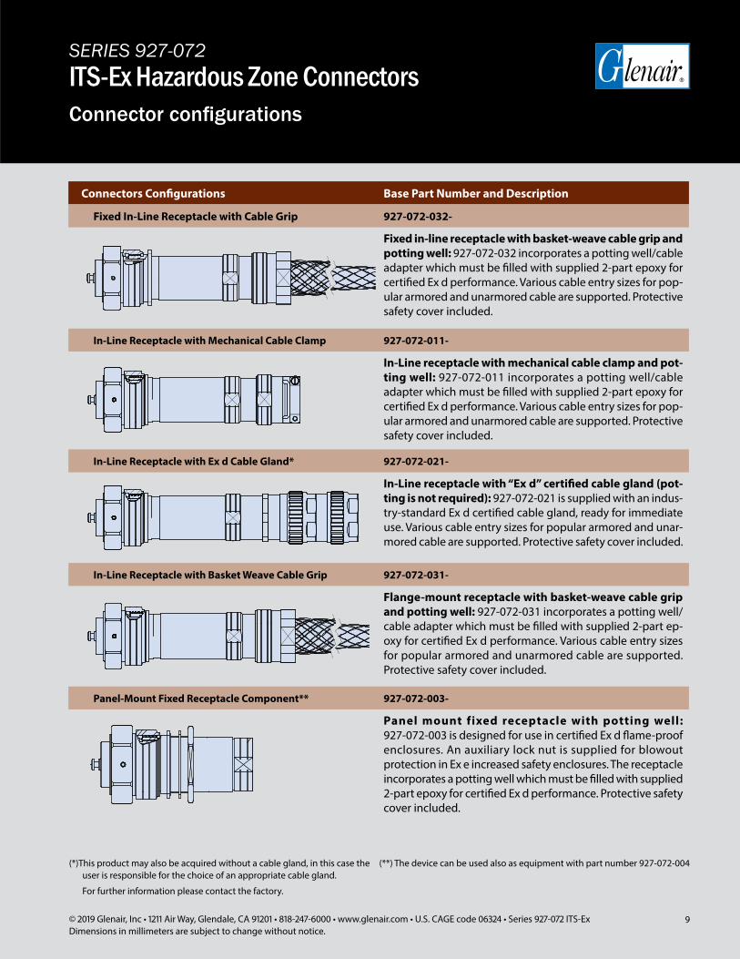
Connectors Configurations Base Part Number and Description
Fixed In-Line Receptacle with Cable Grip 927-072-032-
Fixed in-line receptacle with basket-weave cable grip and potting well: 927-072-032 incorporates a potting well/cable adapter which must be filled with supplied 2-part epoxy for certified Ex d performance. Various cable entry sizes for pop-ular armored and unarmored cable are supported. Protective safety cover included.
In-Line Receptacle with Mechanical Cable Clamp 927-072-011-
In-Line receptacle with mechanical cable clamp and pot-ting well: 927-072-011 incorporates a potting well/cable adapter which must be filled with supplied 2-part epoxy for certified Ex d performance. Various cable entry sizes for pop-ular armored and unarmored cable are supported. Protective safety cover included.
In-Line Receptacle with Ex d Cable Gland* 927-072-021-
In-Line receptacle with “Ex d” certified cable gland (pot-ting is not required): 927-072-021 is supplied with an indus-try-standard Ex d certified cable gland, ready for immediate use. Various cable entry sizes for popular armored and unar-mored cable are supported. Protective safety cover included.
In-Line Receptacle with Basket Weave Cable Grip 927-072-031-
Flange-mount receptacle with basket-weave cable grip and potting well: 927-072-031 incorporates a potting well/cable adapter which must be filled with supplied 2-part ep-oxy for certified Ex d performance. Various cable entry sizes for popular armored and unarmored cable are supported. Protective safety cover included.
Panel-Mount Fixed Receptacle Component** 927-072-003-
Panel mount fixed receptacle with potting well: 927-072-003 is designed for use in certified Ex d flame-proof enclosures. An auxiliary lock nut is supplied for blowout protection in Ex e increased safety enclosures. The receptacle incorporates a potting well which must be filled with supplied 2-part epoxy for certified Ex d performance. Protective safety cover included.
(**) The device can be used also as equipment with part number 927-072-004(*)This product may also be acquired without a cable gland, in this case the user is responsible for the choice of an appropriate cable gland.
For further information please contact the factory.
10 © 2019 Glenair, Inc • 1211 Air Way, Glendale, CA 91201 • 818-247-6000 • www.glenair.com • U.S. CAGE code 06324 • Series 927-072 ITS-ExDimensions in millimeters are subject to change without notice.
SERIES 927-072ITS-Ex Hazardous Zone ConnectorsMating-End Cross-sectional and exploded views
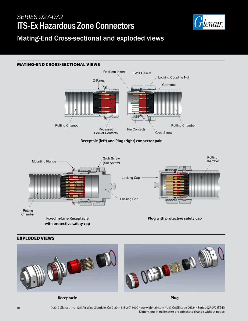
MATING-END CROSS-SECTIONAL VIEWS
EXPLODED VIEWS
Potting Chamber
Potting Chamber
Receptale (left) and Plug (right) connector pair
Fixed In-Line Receptacle with protective safety cap
Plug with protective safety cap
Locking Cap
Locking Cap
Grub Screw (Set Screw)Mounting Flange
Grub Screw
Resilient Insert
O-Rings
Recessed Socket Contacts
Potting Chamber Potting ChamberPin Contacts
Locking Coupling Nut
Grommet
FWD Gasket
Receptacle Plug
11© 2019 Glenair, Inc • 1211 Air Way, Glendale, CA 91201 • 818-247-6000 • www.glenair.com • U.S. CAGE code 06324 • Series 927-072 ITS-ExDimensions in millimeters are subject to change without notice.
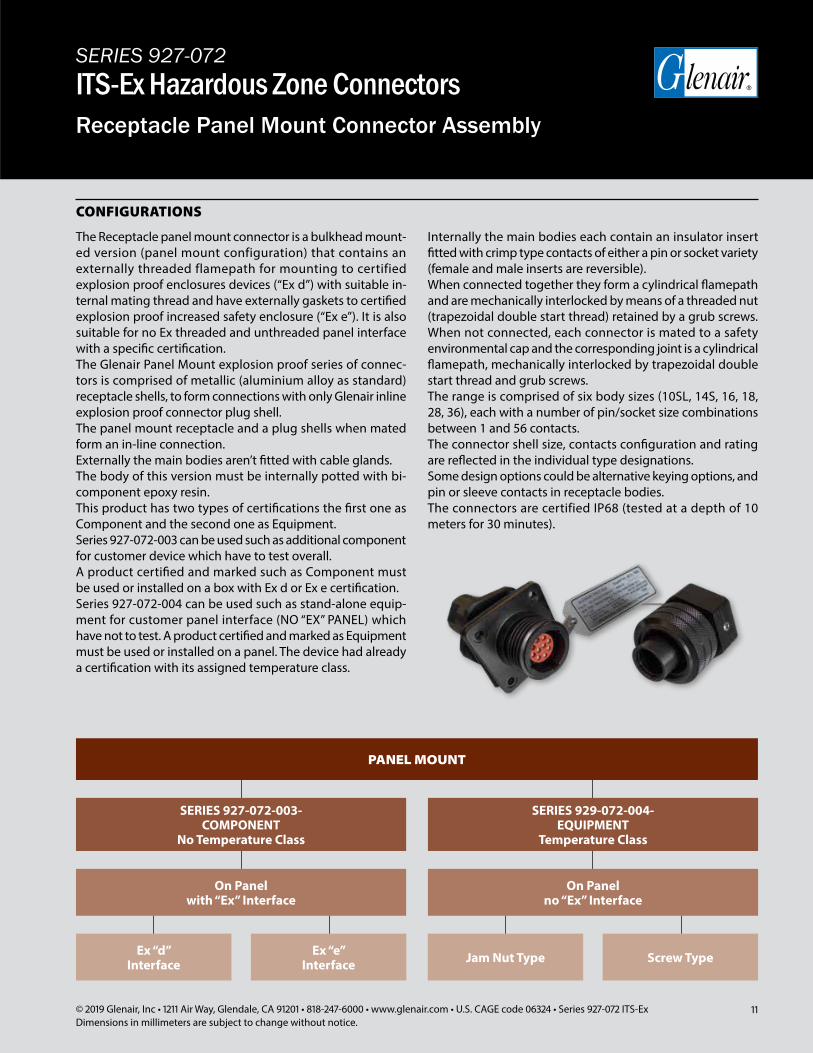
CONFIGURATIONS
The Receptacle panel mount connector is a bulkhead mount-ed version (panel mount configuration) that contains an externally threaded flamepath for mounting to certified explosion proof enclosures devices (“Ex d”) with suitable in-ternal mating thread and have externally gaskets to certified explosion proof increased safety enclosure (“Ex e”). It is also suitable for no Ex threaded and unthreaded panel interface with a specific certification.The Glenair Panel Mount explosion proof series of connec-tors is comprised of metallic (aluminium alloy as standard) receptacle shells, to form connections with only Glenair inline explosion proof connector plug shell.The panel mount receptacle and a plug shells when mated form an in-line connection.Externally the main bodies aren’t fitted with cable glands.The body of this version must be internally potted with bi-component epoxy resin.This product has two types of certifications the first one as Component and the second one as Equipment.Series 927-072-003 can be used such as additional component for customer device which have to test overall.A product certified and marked such as Component must be used or installed on a box with Ex d or Ex e certification.Series 927-072-004 can be used such as stand-alone equip-ment for customer panel interface (NO “EX” PANEL) which have not to test. A product certified and marked as Equipment must be used or installed on a panel. The device had already a certification with its assigned temperature class.
Internally the main bodies each contain an insulator insert fitted with crimp type contacts of either a pin or socket variety (female and male inserts are reversible).When connected together they form a cylindrical flamepath and are mechanically interlocked by means of a threaded nut (trapezoidal double start thread) retained by a grub screws. When not connected, each connector is mated to a safety environmental cap and the corresponding joint is a cylindrical flamepath, mechanically interlocked by trapezoidal double start thread and grub screws.The range is comprised of six body sizes (10SL, 14S, 16, 18, 28, 36), each with a number of pin/socket size combinations between 1 and 56 contacts.The connector shell size, contacts configuration and rating are reflected in the individual type designations.Some design options could be alternative keying options, and pin or sleeve contacts in receptacle bodies.The connectors are certified IP68 (tested at a depth of 10 meters for 30 minutes).
PANEL MOUNT
SERIES 927-072-003-COMPONENT
No Temperature Class
On Panelwith “Ex” Interface
Ex “d”Interface Jam Nut TypeEx “e”
Interface Screw Type
SERIES 929-072-004-EQUIPMENT
Temperature Class
On Panelno “Ex” Interface
SERIES 927-072ITS-Ex Hazardous Zone ConnectorsReceptacle Panel Mount Connector Assembly
12 © 2019 Glenair, Inc • 1211 Air Way, Glendale, CA 91201 • 818-247-6000 • www.glenair.com • U.S. CAGE code 06324 • Series 927-072 ITS-ExDimensions in millimeters are subject to change without notice.
SERIES 927-072ITS-Ex Hazardous Zone ConnectorsPanel Mount Connector Assembly
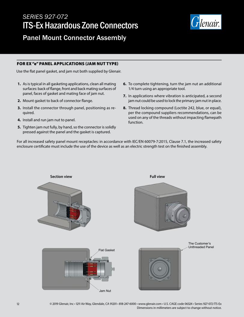
Use the flat panel gasket, and jam nut both supplied by Glenair.
FOR EX “e” PANEL APPLICATIONS (JAM NUT TYPE)
The Customer’sUnthreaded Panel
Section view Full view
Flat Gasket
Jam Nut
The Customer’sUnthreaded Panel
Section view Full view
Flat Gasket
Jam Nut
1. As is typical in all gasketing applications, clean all mating surfaces: back of flange, front and back mating surfaces of panel, faces of gasket and mating face of jam nut.
2. Mount gasket to back of connector flange.
3. Install the connector through panel, positioning as re-quired.
4. Install and run jam nut to panel.
5. Tighten jam nut fully, by hand, so the connector is solidly pressed against the panel and the gasket is captured.
6. To complete tightening, turn the jam nut an additional 1/4 turn using an appropriate tool.
7. In applications where vibration is anticipated, a second jam nut could be used to lock the primary jam nut in place.
8. Thread locking compound (Loctite 242, blue, or equal), per the compound suppliers recommendations, can be used on any of the threads without impacting flamepath function.
For all increased safety panel mount receptacles: in accordance with IEC/EN 60079-7:2015, Clause 7.1, the increased safety enclosure certificate must include the use of the device as well as an electric strength test on the finished assembly.
13© 2019 Glenair, Inc • 1211 Air Way, Glendale, CA 91201 • 818-247-6000 • www.glenair.com • U.S. CAGE code 06324 • Series 927-072 ITS-ExDimensions in millimeters are subject to change without notice.
SERIES 927-072ITS-Ex Hazardous Zone ConnectorsReceptacle Panel Mount Connector Assembly
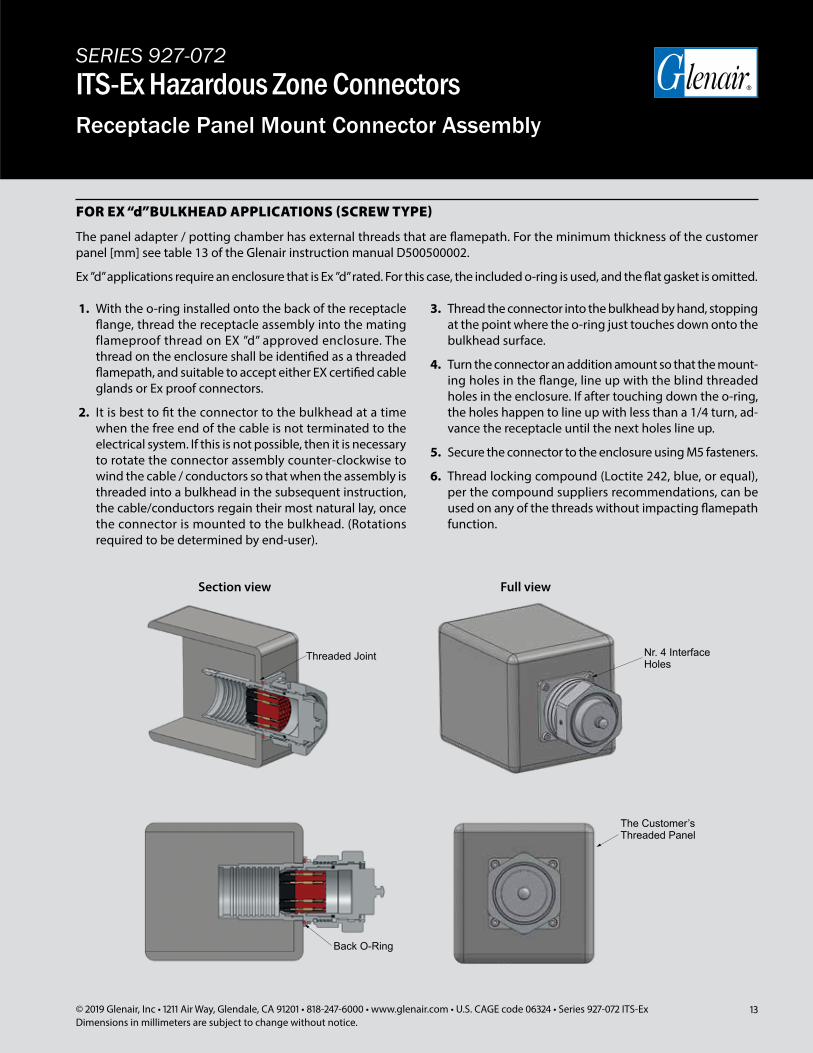
FOR EX “d”BULKHEAD APPLICATIONS (SCREW TYPE)
The panel adapter / potting chamber has external threads that are flamepath. For the minimum thickness of the customer panel [mm] see table 13 of the Glenair instruction manual D500500002.
Ex ”d” applications require an enclosure that is Ex ”d” rated. For this case, the included o-ring is used, and the flat gasket is omitted.
Threaded Joint
Back O-Ring
Nr. 4 InterfaceHoles
The Customer’sThreaded Panel
Section view Full view
Threaded Joint
Back O-Ring
Nr. 4 InterfaceHoles
The Customer’sThreaded Panel
Section view Full view
1. With the o-ring installed onto the back of the receptacle flange, thread the receptacle assembly into the mating flameproof thread on EX ”d” approved enclosure. The thread on the enclosure shall be identified as a threaded flamepath, and suitable to accept either EX certified cable glands or Ex proof connectors.
2. It is best to fit the connector to the bulkhead at a time when the free end of the cable is not terminated to the electrical system. If this is not possible, then it is necessary to rotate the connector assembly counter-clockwise to wind the cable / conductors so that when the assembly is threaded into a bulkhead in the subsequent instruction, the cable/conductors regain their most natural lay, once the connector is mounted to the bulkhead. (Rotations required to be determined by end-user).
3. Thread the connector into the bulkhead by hand, stopping at the point where the o-ring just touches down onto the bulkhead surface.
4. Turn the connector an addition amount so that the mount-ing holes in the flange, line up with the blind threaded holes in the enclosure. If after touching down the o-ring, the holes happen to line up with less than a 1/4 turn, ad-vance the receptacle until the next holes line up.
5. Secure the connector to the enclosure using M5 fasteners.
6. Thread locking compound (Loctite 242, blue, or equal), per the compound suppliers recommendations, can be used on any of the threads without impacting flamepath function.
14 © 2019 Glenair, Inc • 1211 Air Way, Glendale, CA 91201 • 818-247-6000 • www.glenair.com • U.S. CAGE code 06324 • Series 927-072 ITS-ExDimensions in millimeters are subject to change without notice.
SERIES 927-072ITS-Ex Hazardous Zone ConnectorsITS-Ex operation best practices
The following conditions shall be met for safe use of Series ITS-Ex connectors.
SPECIAL CONDITIONS OF SAFE USE
1. Male and female connectors are considered completely mated when the plug coupling nut is fully advanced on the receptacle, and all grub screws are secured.
2. Use Loctite 242 or equivalent (medium strength thread-locker) at threaded joints between the following: plug shell and cable adapter (backshell); receptacle shell and cable adapter (backshell); cable adapter (backshell) and certified cable gland.
3. Never demate connector halves when energized or re-move protective safety covers when an explosive gas or dust atmosphere is present.
4. When a connector half fitted with contact pins is not con-nected to an associated plug or receptacle, it shall not be energized, per IEC 60079-0, clause 20.2.
5. Use protective safety covers whenever connector halves are not mated, being careful to always advance and secure the grub screws. Flame-proof safety caps are a part of the certification, and their use is required to maintain inde-pendent flameproof worthiness of the connector halves.
6. When a connector half fitted with socket contacts is not mated to an associated plug or receptacle, it shall not be re-energized unless it is fitted with an flameproof protec-tive safety cover.
7. Perform connector backpotting step according to Glenair instruction manual D500500000. Backpotting, or use of an Ex d certified cable gland is required for all Hazardous Zone rated equipment and shall be performed carefully and properly, using the 2-part epoxy compound supplied with each connector.
8. Always use suitable cable with a minimum rated operating temperature of 90°C when using rated current according to N.E.C. It is the responsibility of the operator to ensure selected cable is suitable for use in each specific applica-tion, including resistance to aggressive substances and caustic chemicals.
9. Always use suitable cable with a minimum rated operating temperature of 100°C when using rated current extrapo-lated from VG95234. It is the responsibility of the operator to ensure selected cable is suitable for use in each specific application, including resistance to aggressive substances and caustic chemicals.
10. It is not possible to connect to a battery without using a circuit breaker.
11. Series ITS-Ex connectors do not incorporate an external earth/ground. It is the responsibility of the user or installer to ensure adequate earth/ground continuity IAW Glenair instruction manual D500500000.
12. Do not remove Ex marking label and its lanyard from con-nector body or protective safety cover. For flange-mount receptacles mounted to a panel, attach label lanyard directly to a flange mounting hole. Label is required for identification of connector in a certified Ex d application.
13. For multi-pin connectors, calculate current load and temperature rise based on ambient temperature plus the aggregate total of the individual contacts in the insert. MIL-W-5088 specifications shall be used as reference on the subject in as much as pertinent cable de-rating data is included.
15© 2019 Glenair, Inc • 1211 Air Way, Glendale, CA 91201 • 818-247-6000 • www.glenair.com • U.S. CAGE code 06324 • Series 927-072 ITS-ExDimensions in millimeters are subject to change without notice.
SERIES 927-072ITS-Ex Hazardous Zone ConnectorsCable application notes
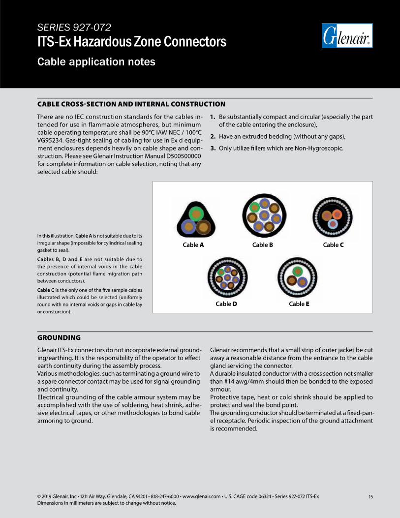
There are no IEC construction standards for the cables in-tended for use in flammable atmospheres, but minimum cable operating temperature shall be 90°C IAW NEC / 100°C VG95234. Gas-tight sealing of cabling for use in Ex d equip-ment enclosures depends heavily on cable shape and con-struction. Please see Glenair Instruction Manual D500500000 for complete information on cable selection, noting that any selected cable should:
1. Be substantially compact and circular (especially the part of the cable entering the enclosure),
2. Have an extruded bedding (without any gaps),
3. Only utilize fillers which are Non-Hygroscopic.
Glenair ITS-Ex connectors do not incorporate external ground-ing/earthing. It is the responsibility of the operator to effect earth continuity during the assembly process.Various methodologies, such as terminating a ground wire to a spare connector contact may be used for signal grounding and continuity.Electrical grounding of the cable armour system may be accomplished with the use of soldering, heat shrink, adhe-sive electrical tapes, or other methodologies to bond cable armoring to ground.
Glenair recommends that a small strip of outer jacket be cut away a reasonable distance from the entrance to the cable gland servicing the connector.A durable insulated conductor with a cross section not smaller than #14 awg/4mm should then be bonded to the exposed armour.Protective tape, heat or cold shrink should be applied to protect and seal the bond point.The grounding conductor should be terminated at a fixed-pan-el receptacle. Periodic inspection of the ground attachment is recommended.
CABLE CROSS-SECTION AND INTERNAL CONSTRUCTION
GROUNDING
In this illustration, Cable A is not suitable due to its irregular shape (impossible for cylindrical sealing gasket to seal).
Cables B, D and E are not suitable due to the presence of internal voids in the cable construction (potential flame migration path between conductors).
Cable C is the only one of the five sample cables illustrated which could be selected (uniformly round with no internal voids or gaps in cable lay or consturcion).
selected.
selected. selected.
Cable C
Cable D Cable E
Cable BCable A
16 © 2019 Glenair, Inc • 1211 Air Way, Glendale, CA 91201 • 818-247-6000 • www.glenair.com • U.S. CAGE code 06324 • Series 927-072 ITS-ExDimensions in millimeters are subject to change without notice.
SERIES 927-072ITS-Ex Hazardous Zone ConnectorsCable application notes
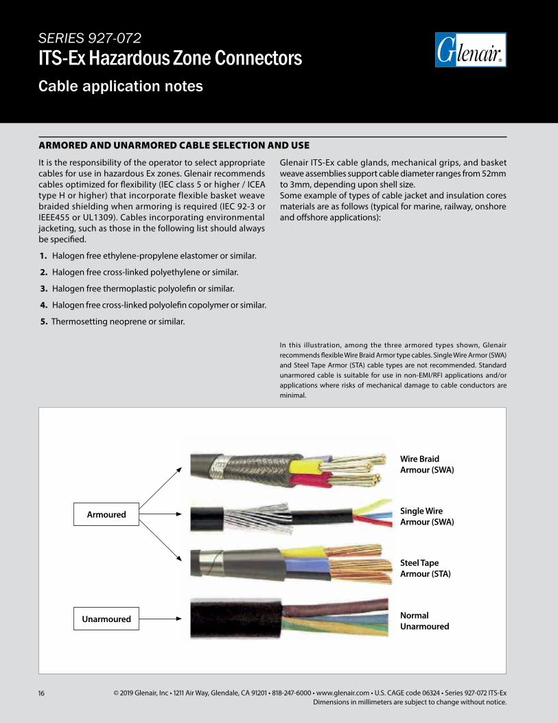
It is the responsibility of the operator to select appropriate cables for use in hazardous Ex zones. Glenair recommends cables optimized for flexibility (IEC class 5 or higher / ICEA type H or higher) that incorporate flexible basket weave braided shielding when armoring is required (IEC 92-3 or IEEE455 or UL1309). Cables incorporating environmental jacketing, such as those in the following list should always be specified.
1. Halogen free ethylene-propylene elastomer or similar.
2. Halogen free cross-linked polyethylene or similar.
3. Halogen free thermoplastic polyolefin or similar.
4. Halogen free cross-linked polyolefin copolymer or similar.
5. Thermosetting neoprene or similar.
Glenair ITS-Ex cable glands, mechanical grips, and basket weave assemblies support cable diameter ranges from 52mm to 3mm, depending upon shell size.Some example of types of cable jacket and insulation cores materials are as follows (typical for marine, railway, onshore and offshore applications):
ARMORED AND UNARMORED CABLE SELECTION AND USE
In this illustration, among the three armored types shown, Glenair recommends flexible Wire Braid Armor type cables. Single Wire Armor (SWA) and Steel Tape Armor (STA) cable types are not recommended. Standard unarmored cable is suitable for use in non-EMI/RFI applications and/or applications where risks of mechanical damage to cable conductors are minimal.
selected.
Armoured
Unarmoured Normal Unarmoured
Steel Tape Armour (STA)
Single Wire Armour (SWA)
Wire Braid Armour (SWA)
17© 2019 Glenair, Inc • 1211 Air Way, Glendale, CA 91201 • 818-247-6000 • www.glenair.com • U.S. CAGE code 06324 • Series 927-072 ITS-ExDimensions in millimeters are subject to change without notice.
SERIES 927-072ITS-Ex Hazardous Zone ConnectorsPotting materials and instructions for In-Line and Plug configuration
EPOXY RESIN POTTING MATERIAL
MIXING INSTRUCTIONS
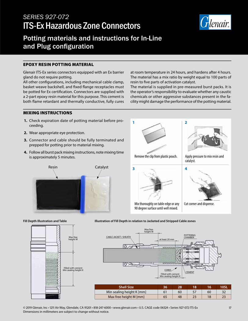
Glenair ITS-Ex series connectors equipped with an Ex barrier gland do not require potting.All other configurations, including mechanical cable clamp, basket weave backshell, and fixed flange receptacles must be potted for Ex certification. Connectors are supplied with a 2-part epoxy resin material for this purpose. This cement is both flame retardant and thermally conductive, fully cures
at room temperature in 24 hours, and hardens after 4 hours. The material has a mix ratio by weight equal to 100 parts of resin to five parts of activation catalyst.The material is supplied in pre-measured burst packs. It is the operator’s responsibility to evaluate whether any caustic chemicals or other aggressive substances present in the fa-cility might damage the performance of the potting material.
Fill Depth Illustration and Table Illustration of Fill Depth in relation to Jacketed and Stripped Cable zones
Shell Size 36 28 18 16 10SLMin sealing height K [mm] 61 60 57 60 32
Max free height M [mm] 65 48 23 18 23
1. Check expiration date of potting material before pro-ceeding.
2. Wear appropriate eye protection.
3. Connector and cable should be fully terminated and prepped for potting prior to material mixing.
4. Follow all burst pack mixing instructions, note mixing time is approximately 5 minutes. Remove the clip from plastic pouch. Apply pressure to mix resin and
catalyst.
Mix thoroughly on table edge or any 90 degree surface until well mixed.
Cut corner and dispense.
1
3
2
4
Filled with cementMin sealing height K
Max freeheight M
Filled with cementMin sealing height K
Max freeheight M
at least 20 mm
POTTERINGCHAMBERCABLE JACKET / SHEATH
CEMENTCORES
Filled with cementMin sealing height K
Max freeheight M
Filled with cementMin sealing height K
Max freeheight M
at least 20 mm
POTTERINGCHAMBERCABLE JACKET / SHEATH
CEMENTCORES
CatalystResin
18 © 2019 Glenair, Inc • 1211 Air Way, Glendale, CA 91201 • 818-247-6000 • www.glenair.com • U.S. CAGE code 06324 • Series 927-072 ITS-ExDimensions in millimeters are subject to change without notice.
SERIES 927-072ITS-Ex Hazardous Zone ConnectorsPotting materials and instructions for Panel Mount configuration
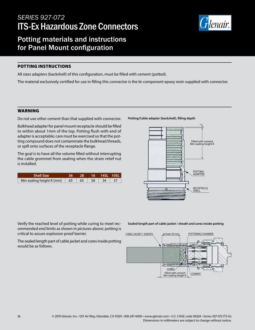
All sizes adapters (backshell) of this configuration, must be filled with cement (potted).
The material exclusively certified for use in filling this connector is the bi-component epoxy resin supplied with connector.
Do not use other cement than that supplied with connector.
Bulkhead adapter for panel mount receptacle should be filled to within about 1mm of the top. Potting flush with end of adapter is acceptable; care must be exercised so that the pot-ting compound does not contaminate the bulkhead threads, or spill onto surfaces of the receptacle flange.
The goal is to have all the volume filled without interrupting the cable grommet from seating when the strain relief nut is installed.
POTTING INSTRUCTIONS
WARNING
Potting/Cable adapter (backshell), filling depth
Sealed length part of cable jacket / sheath and cores inside pottingVerify the reached level of potting while curing to meet rec-ommended end limits as shown in pictures above; potting is critical to assure explosion proof barrier.
The sealed length part of cable jacket and cores inside potting would be as follows.
Filled with cementMin sealing height K
POTTERING CHAMBERCABLE JACKET / SHEATH
CEMENT
CORES
at least 20 mm
Filled with cementMin sealing height K
1
POTTINGADAPTER
RECEPTACLE SHELL
Shell Size 36 28 16 14SL 10SLMin sealing height K [mm] 65 65 58 34 37
Filled with cementMin sealing height K
POTTERING CHAMBERCABLE JACKET / SHEATH
CEMENT
CORES
at least 20 mm
Filled with cementMin sealing height K
1
POTTINGADAPTER
RECEPTACLE SHELL
19© 2019 Glenair, Inc • 1211 Air Way, Glendale, CA 91201 • 818-247-6000 • www.glenair.com • U.S. CAGE code 06324 • Series 927-072 ITS-ExDimensions in millimeters are subject to change without notice.
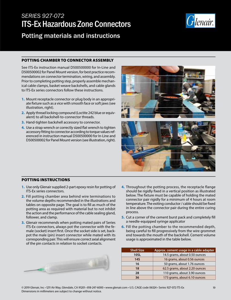
See ITS-Ex instruction manual D500500000 for In-Line and D500500002 for Panel Mount version, for best practice recom-mendations on connector termination, wiring, and assembly. Prior to completing potting step, properly assemble mechan-ical cable clamps, basket weave backshells, and cable glands to ITS-Ex series connectors follow these instructions.
POTTING CHAMBER TO CONNECTOR ASSEMBLY
INSTRUCTIONS MANUAL - D500500000 -
Rev. 3 19/01/2016 Page 44 of 62
Figure 19: Cable adapter (backshell) tightened to receptacle or plugshell
1. Use only Glenair supplied 2-part epoxy resin for potting of ITS-Ex series connectors.
2. Fill potting chamber area behind wire terminations to the volume depths recommended in the illustrations and tables on opposite page. The goal is to fill as much of the potting area as required with material but to not inhibit the action and the performance of the cable sealing gland, follower, and clamp.
3. Glenair recommends when potting mated pairs of Series ITS-Ex connectors, always pot the connector with the fe-male (socket) insert first. Once the socket side is set, back-pot the male (pin) insert connector while mated with its corresponding pair. This will ensure correct axial alignment of the pin contacts in relation to socket contacts.
4. Throughout the potting process, the receptacle flange should be rigidly fixed in a vertical position as illustrated below. The fixture must be capable of holding the mated connector pair rigidly for a minimum of 4 hours at room temperature. The exiting conductor / cable should be fixed in line above the connector pair during the entire curing process.
5. Cut a corner of the cement burst pack and completely fill a needle-equipped syringe applicator
6. Fill the potting chamber to the recommended depth, being careful to fill progressively from the wire grommet end towards the mouth of the backshell. Cement volume usage is approximated in the table below.
POTTING INSTRUCTIONS
INSTRUCTIONS MANUAL - D500500000 -
Rev. 3 19/01/2016 Page 34 of 62
Figure 12: Connector coupled to its mate
Figure 13: Female contact insertion
Figure 14: Contact insertion
SERIES 927-072ITS-Ex Hazardous Zone ConnectorsPotting materials and instructions
Shell Size Approx. cement usage in a cable adapter10SL 14.5 grams, about 0.50 ounces14S 16 grams, about 0.56 ounces16 50 grams, about 1.76 ounces18 62.5 grams, about 2.20 ounces28 110 grams, about 3.90 ounces36 173 grams, about 6.10 ounces
1. Mount receptacle connector or plug body in an appropri-ate fixture such as a vice with smooth face or soft jaws (see illustration, right).
2. Apply thread locking compound (Loctite 242 blue or equiv-alent) to all backshell-to-connector threads.
3. Hand-tighten backshell accessory to connector.4. Use a strap wrench or correctly sized flat wrench to tighten
accessory fitting to connector according to torque values ref-erenced in instruction manual D500500000 for In-Line and D500500002 for Panel Mount version (see illustration, right).
20 © 2019 Glenair, Inc • 1211 Air Way, Glendale, CA 91201 • 818-247-6000 • www.glenair.com • U.S. CAGE code 06324 • Series 927-072 ITS-ExDimensions in millimeters are subject to change without notice.
SERIES 927-072ITS-Ex Hazardous Zone ConnectorsPanel Cut-outs
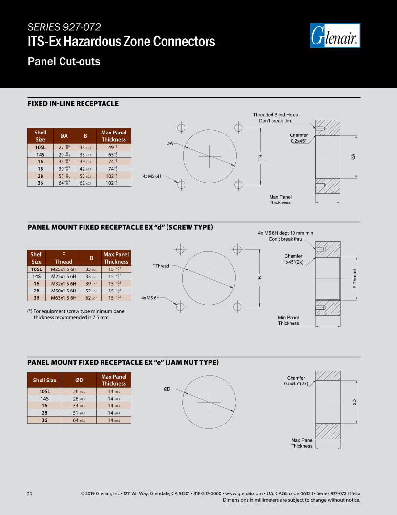
FIXED IN-LINE RECEPTACLE
PANEL MOUNT FIXED RECEPTACLE EX “d” (SCREW TYPE)
PANEL MOUNT FIXED RECEPTACLE EX “e” (JAM NUT TYPE)
ShellSize ØD Max Panel
Thickness
10SL 26 ±0.5 14 ±0.5
14S 26 ±0.5 14 ±0.5
16 33 ±0.5 14 ±0.5
28 51 ±0.5 14 ±0.5
36 64 ±0.5 14 ±0.5
Chamfer0.2x45°
ØD
ØA
B
4x M5 6H
F Thread
B
4x M5 6H
Max PanelThickness
Max PanelThickness
Chamfer0.5x45°(2x)
Min PanelThickness
Chamfer1x45°(2x)
F Th
read
ShellSize ØA B Max Panel
Thickness
10SL 27 33 ±0.1 49
14S 29 33 ±0.1 65
16 35 39 ±0.1 74
18 39 42 ±0.1 74
28 55 52 ±0.1 102
36 64 62 ±0.1 120
+1 0
+0.50
0-0.5
+0.50
+0.50
0-0.5
+0.50
+1 0
+1 0
+1 0
+1 0
+1 0
ShellSize
FThread B Min Panel
Thickness*
10SL M25x1.5 6H 33 ±0.1 15
14S M25x1.5 6H 33 ±0.1 15
16 M32x1.5 6H 39 ±0.1 15
28 M50x1.5 6H 52 ±0.1 15
36 M63x1.5 6H 62 ±0.1 15
+0.50
+0.50
+0.50
+0.50
+0.50
ØA
ØD
(*) For equipment screw type minimum panel thickness recommended is 7.5 mm
Threaded Blind Holes Don’t break thru
4x M5 6H dept 10 mm min Don’t break thru
Shell Size
ØA BMax Panel Thickness
10SL 27 33 ±0.1 4914S 29 33 ±0.1 6516 35 39 ±0.1 7418 39 42 ±0.1 7428 55 52 ±0.1 10236 64 62 ±0.1 102
0+0.5
0+1
-0.50
0+1
0+0.5
0+1
0+0.5
0+1
-0.50
0+1
0+0.5
0+1
Shell Size
F Thread B Max Panel
Thickness10SL M25x1.5 6H 33 ±0.1 1514S M25x1.5 6H 33 ±0.1 1516 M32x1.5 6H 39 ±0.1 1528 M50x1.5 6H 52 ±0.1 1536 M63x1.5 6H 62 ±0.1 15
0+0.5
0+0.5
0+0.5
0+0.5
0+0.5
(*) For equipment screw type minimum panel thickness recommended is 7.5 mm
Shell Size ØD Max Panel Thickness
10SL 26 ±0.5 14 ±0.5
14S 26 ±0.5 14 ±0.5
16 33 ±0.5 14 ±0.5
28 51 ±0.5 14 ±0.5
36 64 ±0.5 14 ±0.5
21© 2019 Glenair, Inc • 1211 Air Way, Glendale, CA 91201 • 818-247-6000 • www.glenair.com • U.S. CAGE code 06324 • Series 927-072 ITS-ExDimensions in millimeters are subject to change without notice.
SERIES 927-072ITS-Ex Hazardous Zone ConnectorsElectrical Performance
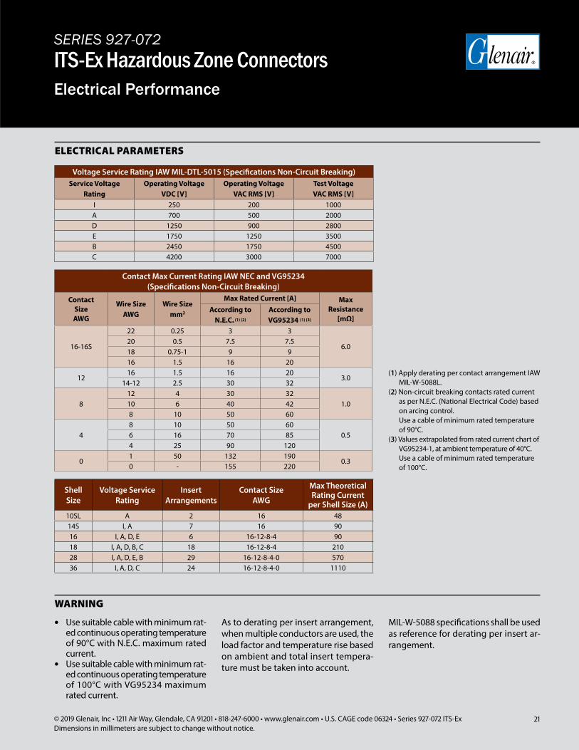
ELECTRICAL PARAMETERS
Voltage Service Rating IAW MIL-DTL-5015 (Specifications Non-Circuit Breaking)Service Voltage
RatingOperating Voltage
VDC [V]Operating Voltage
VAC RMS [V]Test VoltageVAC RMS [V]
I 250 200 1000A 700 500 2000D 1250 900 2800E 1750 1250 3500B 2450 1750 4500C 4200 3000 7000
Contact Max Current Rating IAW NEC and VG95234 (Specifications Non-Circuit Breaking)
Contact SizeAWG
Wire SizeAWG
Wire Sizemm2
Max Rated Current [A] Max Resistance
[mΩ]According to
N.E.C. (1) (2)
According to VG95234 (1) (3)
16-16S
22 0.25 3 3
6.020 0.5 7.5 7.518 0.75-1 9 916 1.5 16 20
1216 1.5 16 20
3.014-12 2.5 30 32
812 4 30 32
1.010 6 40 428 10 50 60
48 10 50 60
0.56 16 70 854 25 90 120
01 50 132 190
0.30 - 155 220
(1) Apply derating per contact arrangement IAW MIL-W-5088L.
(2) Non-circuit breaking contacts rated current as per N.E.C. (National Electrical Code) based on arcing control. Use a cable of minimum rated temperature of 90°C.
(3) Values extrapolated from rated current chart of VG95234-1, at ambient temperature of 40°C. Use a cable of minimum rated temperature of 100°C.
WARNING
• Use suitable cable with minimum rat-ed continuous operating temperature of 90°C with N.E.C. maximum rated current.
• Use suitable cable with minimum rat-ed continuous operating temperature of 100°C with VG95234 maximum rated current.
As to derating per insert arrangement, when multiple conductors are used, the load factor and temperature rise based on ambient and total insert tempera-ture must be taken into account.
MIL-W-5088 specifications shall be used as reference for derating per insert ar-rangement.
Shell Size
Voltage Service Rating
Insert Arrangements
Contact SizeAWG
Max Theoretical Rating Current
per Shell Size (A)10SL A 2 16 4814S I, A 7 16 9016 I, A, D, E 6 16-12-8-4 9018 I, A, D, B, C 18 16-12-8-4 21028 I, A, D, E, B 29 16-12-8-4-0 57036 I, A, D, C 24 16-12-8-4-0 1110
22 © 2019 Glenair, Inc • 1211 Air Way, Glendale, CA 91201 • 818-247-6000 • www.glenair.com • U.S. CAGE code 06324 • Series 927-072 ITS-ExDimensions in millimeters are subject to change without notice.
SERIES 927-072ITS-Ex Hazardous Zone ConnectorsContact arrangements
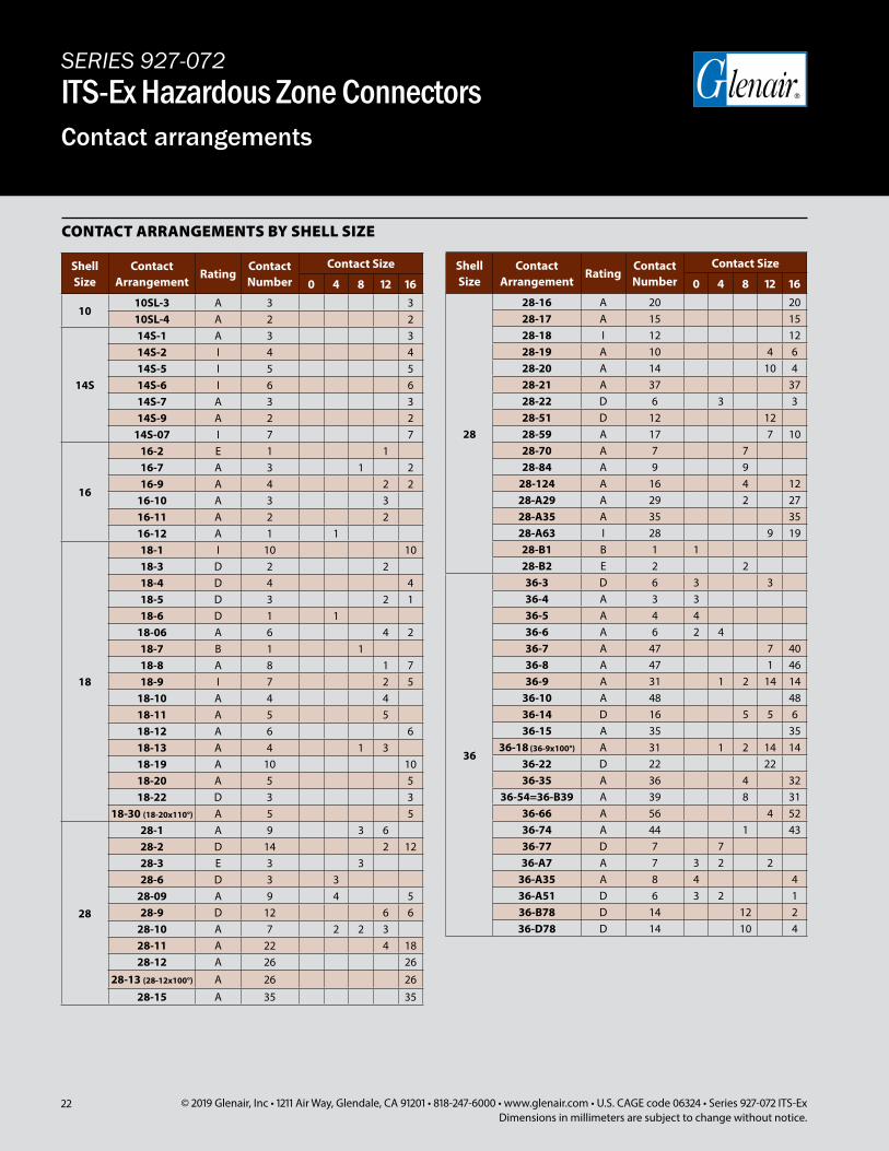
CONTACT ARRANGEMENTS BY SHELL SIZE
Shell Size
Contact Arrangement
RatingContact Number
Contact Size
0 4 8 12 16
1010SL-3 A 3 310SL-4 A 2 2
14S
14S-1 A 3 314S-2 I 4 414S-5 I 5 514S-6 I 6 614S-7 A 3 314S-9 A 2 2
14S-07 I 7 7
16
16-2 E 1 116-7 A 3 1 216-9 A 4 2 2
16-10 A 3 316-11 A 2 216-12 A 1 1
18
18-1 I 10 1018-3 D 2 218-4 D 4 418-5 D 3 2 118-6 D 1 1
18-06 A 6 4 218-7 B 1 118-8 A 8 1 718-9 I 7 2 5
18-10 A 4 418-11 A 5 518-12 A 6 618-13 A 4 1 318-19 A 10 1018-20 A 5 518-22 D 3 3
18-30 (18-20x110°) A 5 5
28
28-1 A 9 3 628-2 D 14 2 1228-3 E 3 328-6 D 3 3
28-09 A 9 4 528-9 D 12 6 6
28-10 A 7 2 2 328-11 A 22 4 1828-12 A 26 26
28-13 (28-12x100°) A 26 2628-15 A 35 35
Shell Size
Contact Arrangement
RatingContact Number
Contact Size
0 4 8 12 16
28
28-16 A 20 2028-17 A 15 1528-18 I 12 1228-19 A 10 4 628-20 A 14 10 428-21 A 37 3728-22 D 6 3 328-51 D 12 1228-59 A 17 7 1028-70 A 7 728-84 A 9 9
28-124 A 16 4 1228-A29 A 29 2 2728-A35 A 35 3528-A63 I 28 9 1928-B1 B 1 128-B2 E 2 2
36
36-3 D 6 3 336-4 A 3 336-5 A 4 436-6 A 6 2 436-7 A 47 7 4036-8 A 47 1 4636-9 A 31 1 2 14 14
36-10 A 48 4836-14 D 16 5 5 636-15 A 35 35
36-18 (36-9x100°) A 31 1 2 14 1436-22 D 22 2236-35 A 36 4 32
36-54=36-B39 A 39 8 3136-66 A 56 4 5236-74 A 44 1 4336-77 D 7 736-A7 A 7 3 2 2
36-A35 A 8 4 436-A51 D 6 3 2 136-B78 D 14 12 236-D78 D 14 10 4
23© 2019 Glenair, Inc • 1211 Air Way, Glendale, CA 91201 • 818-247-6000 • www.glenair.com • U.S. CAGE code 06324 • Series 927-072 ITS-ExDimensions in millimeters are subject to change without notice.
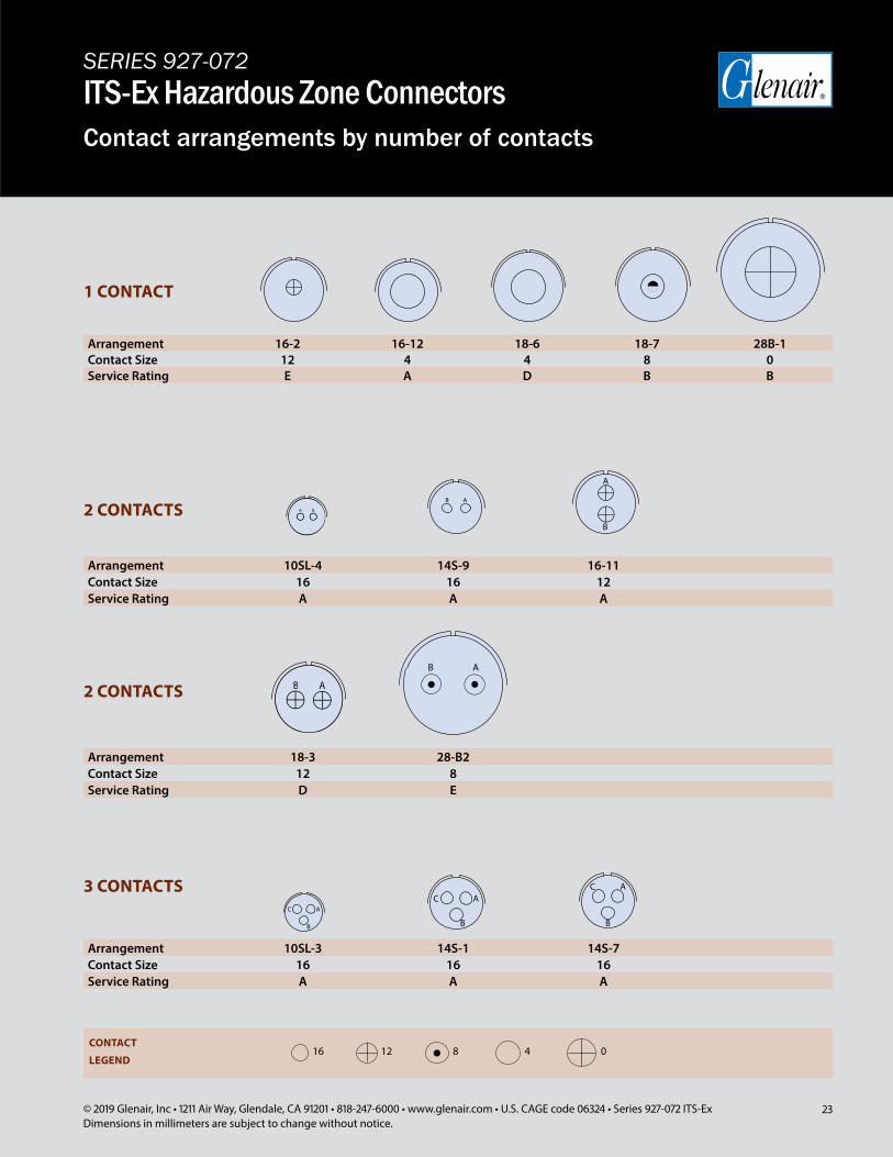
SERIES 927-072ITS-Ex Hazardous Zone ConnectorsContact arrangements by number of contacts
BA
B AB A
Arrangement 16-2 16-12 18-6 18-7 28B-1Contact Size 12 4 4 8 0Service Rating E A D B B
Arrangement 10SL-4 14S-9 16-11Contact Size 16 16 12Service Rating A A A
Arrangement 18-3 28-B2Contact Size 12 8Service Rating D E
Arrangement 10SL-3 14S-1 14S-7Contact Size 16 16 16Service Rating A A A
1 CONTACT
2 CONTACTS
2 CONTACTS
3 CONTACTS
CONTACT
LEGEND16 12 8 04
B
A
C A
B
C A
B
C A
B
24 © 2019 Glenair, Inc • 1211 Air Way, Glendale, CA 91201 • 818-247-6000 • www.glenair.com • U.S. CAGE code 06324 • Series 927-072 ITS-ExDimensions in millimeters are subject to change without notice.
SERIES 927-072ITS-Ex Hazardous Zone ConnectorsContact arrangements by number of contacts
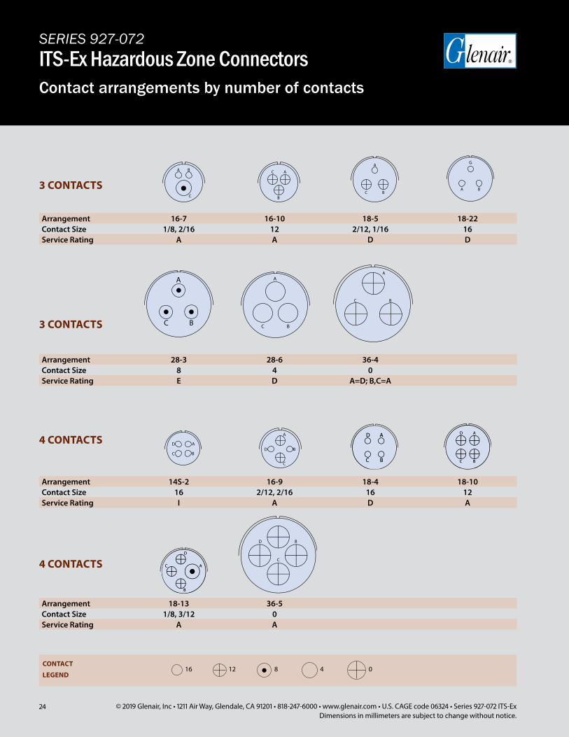
Arrangement 14S-2 16-9 18-4 18-10Contact Size 16 2/12, 2/16 16 12Service Rating I A D A
Arrangement 28-3 28-6 36-4Contact Size 8 4 0Service Rating E D A=D; B,C=A
Arrangement 16-7 16-10 18-5 18-22Contact Size 1/8, 2/16 12 2/12, 1/16 16Service Rating A A D D
Arrangement 18-13 36-5Contact Size 1/8, 3/12 0Service Rating A A
4 CONTACTS
3 CONTACTS
3 CONTACTS
4 CONTACTS
CONTACT
LEGEND16 12 8 04
C
D B
A B
G
D A
C B
C
D B
A
25© 2019 Glenair, Inc • 1211 Air Way, Glendale, CA 91201 • 818-247-6000 • www.glenair.com • U.S. CAGE code 06324 • Series 927-072 ITS-ExDimensions in millimeters are subject to change without notice.
SERIES 927-072ITS-Ex Hazardous Zone ConnectorsContact arrangements by number of contacts
BA
DN G
C
E
D A
BCC
D
B
E
A
F
C
AE
B
F
C
AE
B
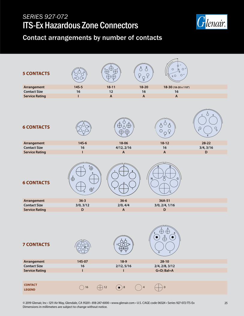
Arrangement 14S-5 18-11 18-20 18-30 (18-20 x 110°)
Contact Size 16 12 16 16Service Rating I A A A
Arrangement 14S-6 18-06 18-12 28-22Contact Size 16 4/12, 2/16 16 3/4, 3/16Service Rating I A A D
Arrangement 36-3 36-6 36A-51Contact Size 3/0, 3/12 2/0, 4/4 3/0, 2/4, 1/16Service Rating D A D
5 CONTACTS
6 CONTACTS
6 CONTACTS
Arrangement 14S-07 18-9 28-10Contact Size 16 2/12, 5/16 2/4, 2/8, 3/12Service Rating I I G=D; Bal=A
7 CONTACTS
AB
C
DE
18-2
0
110˚
D C
EA
B
F B
E
D
C
A
ED
F
A
C
B
CONTACT
LEGEND16 12 8 04
26 © 2019 Glenair, Inc • 1211 Air Way, Glendale, CA 91201 • 818-247-6000 • www.glenair.com • U.S. CAGE code 06324 • Series 927-072 ITS-ExDimensions in millimeters are subject to change without notice.
SERIES 927-072ITS-Ex Hazardous Zone ConnectorsContact arrangements by number of contacts
I
F
E
C
D
J
G
H
B
A
I
F
E
C
D
J
G
H
B
A
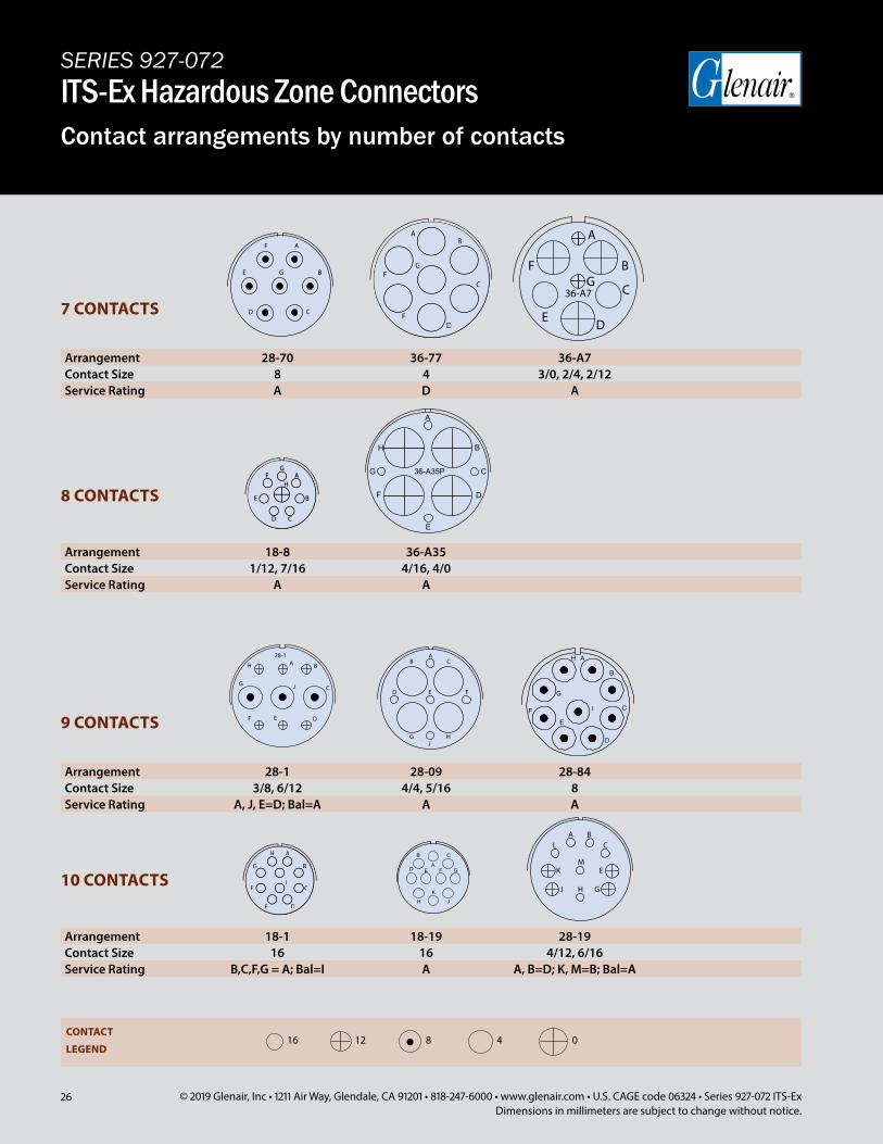
Arrangement 18-1 18-19 28-19Contact Size 16 16 4/12, 6/16Service Rating B,C,F,G = A; Bal=I A A, B=D; K, M=B; Bal=A
10 CONTACTSA
B C
E F
J
D G
K
H
Arrangement 28-70 36-77 36-A7Contact Size 8 4 3/0, 2/4, 2/12Service Rating A D A
Arrangement 28-1 28-09 28-84Contact Size 3/8, 6/12 4/4, 5/16 8Service Rating A, J, E=D; Bal=A A A
7 CONTACTS
9 CONTACTS
AB
FG
C
DE
AB
FG
C
DE
A
Arrangement 18-8 36-A35Contact Size 1/12, 7/16 4/16, 4/0Service Rating A A
8 CONTACTS
B
CG
H
A
D
E
F
36-A35P
BA
C
E DF
G
H
J
28-1
CONTACT
LEGEND16 12 8 04
27© 2019 Glenair, Inc • 1211 Air Way, Glendale, CA 91201 • 818-247-6000 • www.glenair.com • U.S. CAGE code 06324 • Series 927-072 ITS-ExDimensions in millimeters are subject to change without notice.
SERIES 927-072ITS-Ex Hazardous Zone ConnectorsContact arrangements by number of contacts
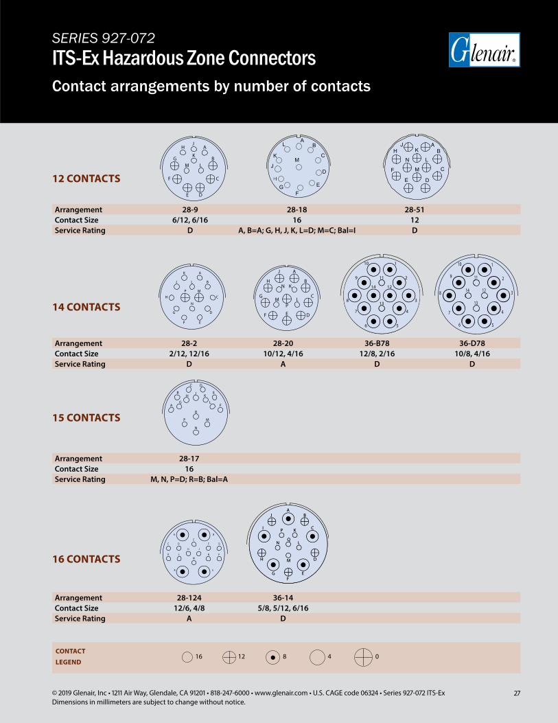
Arrangement 28-9 28-18 28-51Contact Size 6/12, 6/16 16 12Service Rating D A, B=A; G, H, J, K, L=D; M=C; Bal=I D
Arrangement 28-2 28-20 36-B78 36-D78Contact Size 2/12, 12/16 10/12, 4/16 12/8, 2/16 10/8, 4/16Service Rating D A D D
Arrangement 28-17Contact Size 16Service Rating M, N, P=D; R=B; Bal=A
12 CONTACTS
Arrangement 28-124 36-14Contact Size 12/6, 4/8 5/8, 5/12, 6/16Service Rating A D
14 CONTACTS
15 CONTACTS
16 CONTACTS
1
2
38
47
13
119
10
14 12
56
CONTACT
LEGEND16 12 8 04
28 © 2019 Glenair, Inc • 1211 Air Way, Glendale, CA 91201 • 818-247-6000 • www.glenair.com • U.S. CAGE code 06324 • Series 927-072 ITS-ExDimensions in millimeters are subject to change without notice.
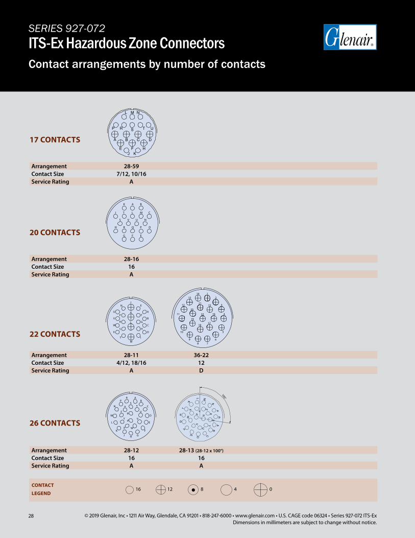
Arrangement 28-16Contact Size 16Service Rating A
Arrangement 28-11 36-22Contact Size 4/12, 18/16 12Service Rating A D
Arrangement 28-12 28-13 (28-12 x 100°)
Contact Size 16 16Service Rating A A
22 CONTACTS
26 CONTACTS
20 CONTACTS
Arrangement 28-59Contact Size 7/12, 10/16Service Rating A
17 CONTACTS
17
b
K
ML
HJ
G
WX
dY
V
F
E
D
N
Z P
aS
T
U
B
RA
C
100°
CONTACT
LEGEND16 12 8 04
SERIES 927-072ITS-Ex Hazardous Zone ConnectorsContact arrangements by number of contacts
29© 2019 Glenair, Inc • 1211 Air Way, Glendale, CA 91201 • 818-247-6000 • www.glenair.com • U.S. CAGE code 06324 • Series 927-072 ITS-ExDimensions in millimeters are subject to change without notice.
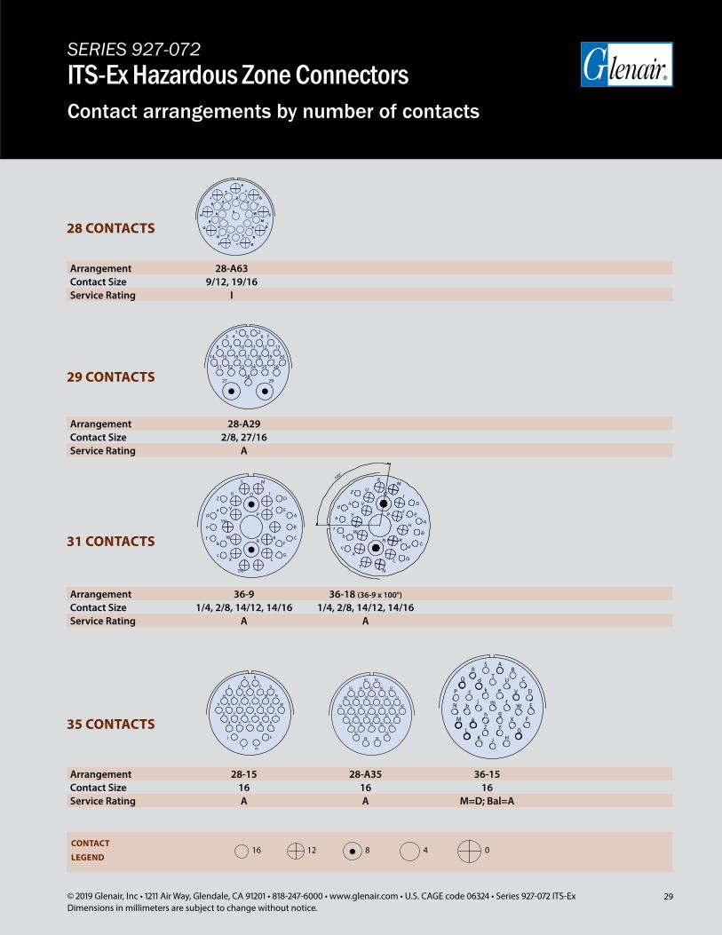
Arrangement 28-A63Contact Size 9/12, 19/16Service Rating I
Arrangement 28-A29Contact Size 2/8, 27/16Service Rating A
Arrangement 36-9 36-18 (36-9 x 100°)
Contact Size 1/4, 2/8, 14/12, 14/16 1/4, 2/8, 14/12, 14/16Service Rating A A
28 CONTACTS
Arrangement 28-15 28-A35 36-15Contact Size 16 16 16Service Rating A A M=D; Bal=A
29 CONTACTS
31 CONTACTS
35 CONTACTS
YH
c
f
e
b
TN
R
X
W
LG
KF
Z
da
PV
S
U OD
J E
I
M
C
B
A
CONTACT
LEGEND16 12 8 04
SERIES 927-072ITS-Ex Hazardous Zone ConnectorsContact arrangements by number of contacts
30 © 2019 Glenair, Inc • 1211 Air Way, Glendale, CA 91201 • 818-247-6000 • www.glenair.com • U.S. CAGE code 06324 • Series 927-072 ITS-ExDimensions in millimeters are subject to change without notice.
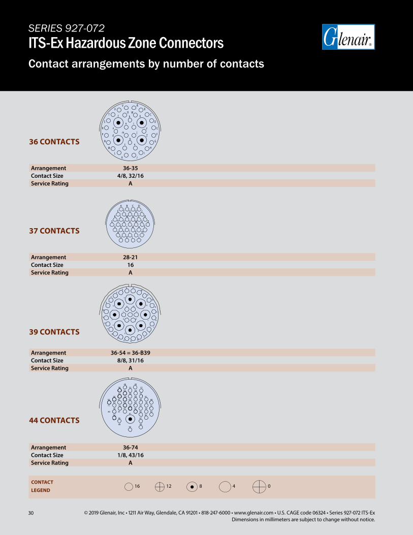
Arrangement 28-21Contact Size 16Service Rating A
Arrangement 36-54 = 36-B39Contact Size 8/8, 31/16Service Rating A
Arrangement 36-74Contact Size 1/8, 43/16Service Rating A
39 CONTACTS
44 CONTACTS
37 CONTACTS
Arrangement 36-35Contact Size 4/8, 32/16Service Rating A
36 CONTACTS
CONTACT
LEGEND16 12 8 04
SERIES 927-072ITS-Ex Hazardous Zone ConnectorsContact arrangements by number of contacts
31© 2019 Glenair, Inc • 1211 Air Way, Glendale, CA 91201 • 818-247-6000 • www.glenair.com • U.S. CAGE code 06324 • Series 927-072 ITS-ExDimensions in millimeters are subject to change without notice.
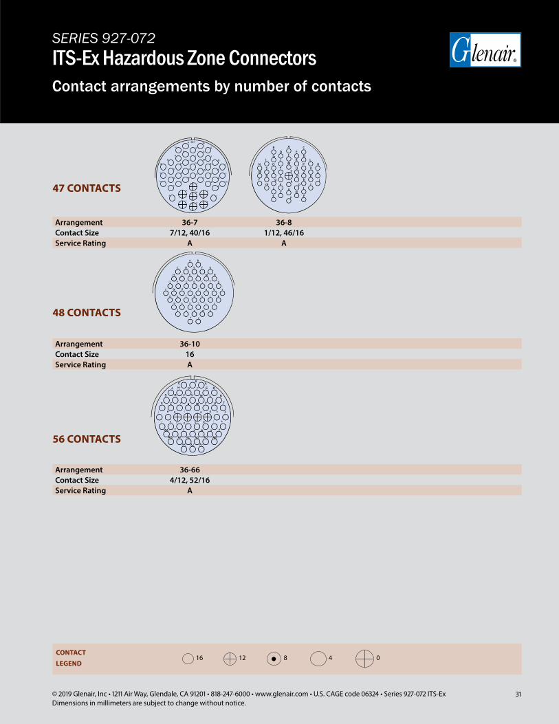
Arrangement 36-66Contact Size 4/12, 52/16Service Rating A
56 CONTACTS
Arrangement 36-10Contact Size 16Service Rating A
48 CONTACTS
Arrangement 36-7 36-8Contact Size 7/12, 40/16 1/12, 46/16Service Rating A A
47 CONTACTS
CONTACT
LEGEND16 12 8 04
SERIES 927-072ITS-Ex Hazardous Zone ConnectorsContact arrangements by number of contacts
32 © 2019 Glenair, Inc • 1211 Air Way, Glendale, CA 91201 • 818-247-6000 • www.glenair.com • U.S. CAGE code 06324 • Series 927-072 ITS-ExDimensions in millimeters are subject to change without notice.
SERIES 927-072ITS-Ex Hazardous Zone ConnectorsContact arrangements by number of contacts
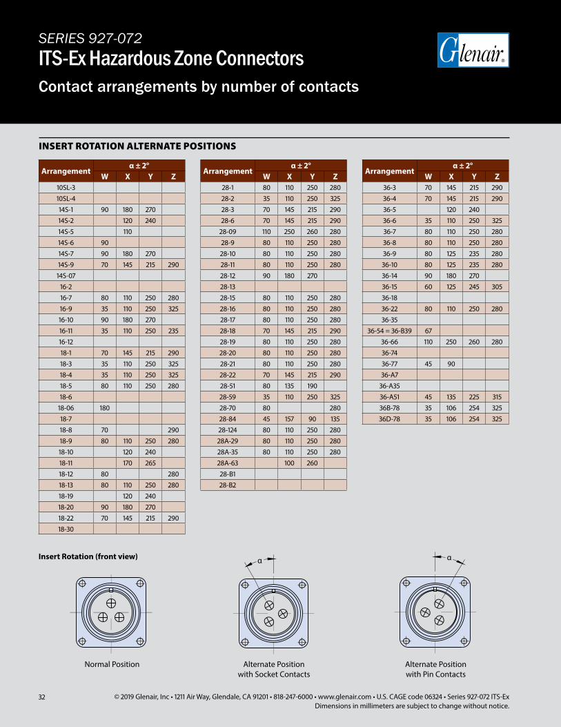
Arrangementα ± 2°
W X Y Z10SL-310SL-414S-1 90 180 27014S-2 120 24014S-5 11014S-6 9014S-7 90 180 27014S-9 70 145 215 29014S-07
16-216-7 80 110 250 28016-9 35 110 250 32516-10 90 180 27016-11 35 110 250 23516-1218-1 70 145 215 29018-3 35 110 250 32518-4 35 110 250 32518-5 80 110 250 28018-6
18-06 18018-718-8 70 29018-9 80 110 250 28018-10 120 24018-11 170 26518-12 80 28018-13 80 110 250 28018-19 120 24018-20 90 180 27018-22 70 145 215 29018-30
Normal Position Alternate Positionwith Pin Contacts
Alternate Positionwith Socket Contacts
Insert Rotation (front view) α
INSERT ROTATION ALTERNATE POSITIONS
Arrangementα ± 2°
W X Y Z28-1 80 110 250 28028-2 35 110 250 32528-3 70 145 215 29028-6 70 145 215 290
28-09 110 250 260 28028-9 80 110 250 28028-10 80 110 250 28028-11 80 110 250 28028-12 90 180 27028-1328-15 80 110 250 28028-16 80 110 250 28028-17 80 110 250 28028-18 70 145 215 29028-19 80 110 250 28028-20 80 110 250 28028-21 80 110 250 28028-22 70 145 215 29028-51 80 135 19028-59 35 110 250 32528-70 80 28028-84 45 157 90 13528-124 80 110 250 28028A-29 80 110 250 28028A-35 80 110 250 28028A-63 100 26028-B128-B2
Arrangementα ± 2°
W X Y Z36-3 70 145 215 29036-4 70 145 215 29036-5 120 24036-6 35 110 250 32536-7 80 110 250 28036-8 80 110 250 28036-9 80 125 235 28036-10 80 125 235 28036-14 90 180 27036-15 60 125 245 30536-1836-22 80 110 250 28036-35
36-54 = 36-B39 6736-66 110 250 260 28036-7436-77 45 9036-A7
36-A3536-A51 45 135 225 31536B-78 35 106 254 32536D-78 35 106 254 325

Designed for safe operation in petrochemical refineries, oil & gas drilling platforms, and other explosion zone applications, the Glenair ITS-Ex series connector is opti-
mized for life-of-system durability and reliability. Qualified by the globally-recognized IEC and IECEx standards bodies, the connector series is suitable for use in application areas where flammable gases and vapors are present as a normal condition of operation (group IIC) and with temperature classes T6 and T5, zones 1 and 2; and for applications where potentially flammable dust is present as a normal condition of operation (group IIIC) and with temperature classes T80°C and T95°C in zone 21 and 22.
Series ITS-Ex is designed for easy and repeatable termination of armored and unarmored cables built to IEEE 45, IEC, BS, DIN, and JIC standards. A full range of power and signal contacts, from size #16 to size #0 in over 40 insert arrangements are available to address all common voltage, wire size and connector service class ratings.
Special Ex design attributes of the series include an integral labyrinth flame path cooling zone, 2-part epoxy potting well, fixed in-line receptacles for attachment of cables to cable management brackets and trays, set screw (grub screw) secured protective safety covers, and durable life-of-system Ex marking labels.
APPLICATION AND INSTALLATION
Glenair assembly procedure D500500000 for In-Line and D500500002 for Panel Mount version to be referenced for certified operator assembly
Always use Loctite 242 or equivalent (medium strength threadlocker) on all threaded joints
All set screws (grub screws) must be fully tightened during installation and operation
Industrial-strength power and signal connector series qualified for use in hazardous zone interconnect applications
SERIES ITS-Ex
© 2019 Glenair, Inc • 1211 Air Way, Glendale, CA 91201 • 818-247-6000 • www.glenair.com • U.S. CAGE code 06324
34 © 2019 Glenair, Inc • 1211 Air Way, Glendale, CA 91201 • 818-247-6000 • www.glenair.com • U.S. CAGE code 06324 • Series 927-072 ITS-ExDimensions in millimeters are subject to change without notice.
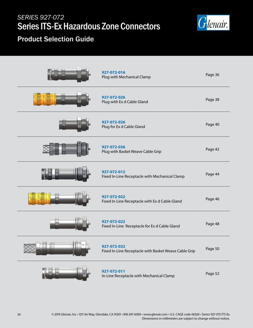
927-072-016 Plug with Mechanical Clamp Page 36
927-072-026 Plug with Ex d Cable Gland Page 38
927-072-026 Plug for Ex d Cable Gland Page 40
927-072-036 Plug with Basket Weave Cable Grip Page 42
927-072-012 Fixed In-Line Receptacle with Mechanical Clamp Page 44
927-072-022 Fixed In-Line Receptacle with Ex d Cable Gland Page 46
927-072-022 Fixed In-Line Receptacle for Ex d Cable Gland Page 48
927-072-032 Fixed In-Line Receptacle with Basket Weave Cable Grip Page 50
927-072-011 In-Line Receptacle with Mechanical Clamp Page 52
SERIES 927-072Series ITS-Ex Hazardous Zone ConnectorsProduct Selection Guide
35© 2019 Glenair, Inc • 1211 Air Way, Glendale, CA 91201 • 818-247-6000 • www.glenair.com • U.S. CAGE code 06324 • Series 927-072 ITS-ExDimensions in millimeters are subject to change without notice.
SERIES 927-072Series ITS-Ex Hazardous Zone ConnectorsProduct Selection Guide
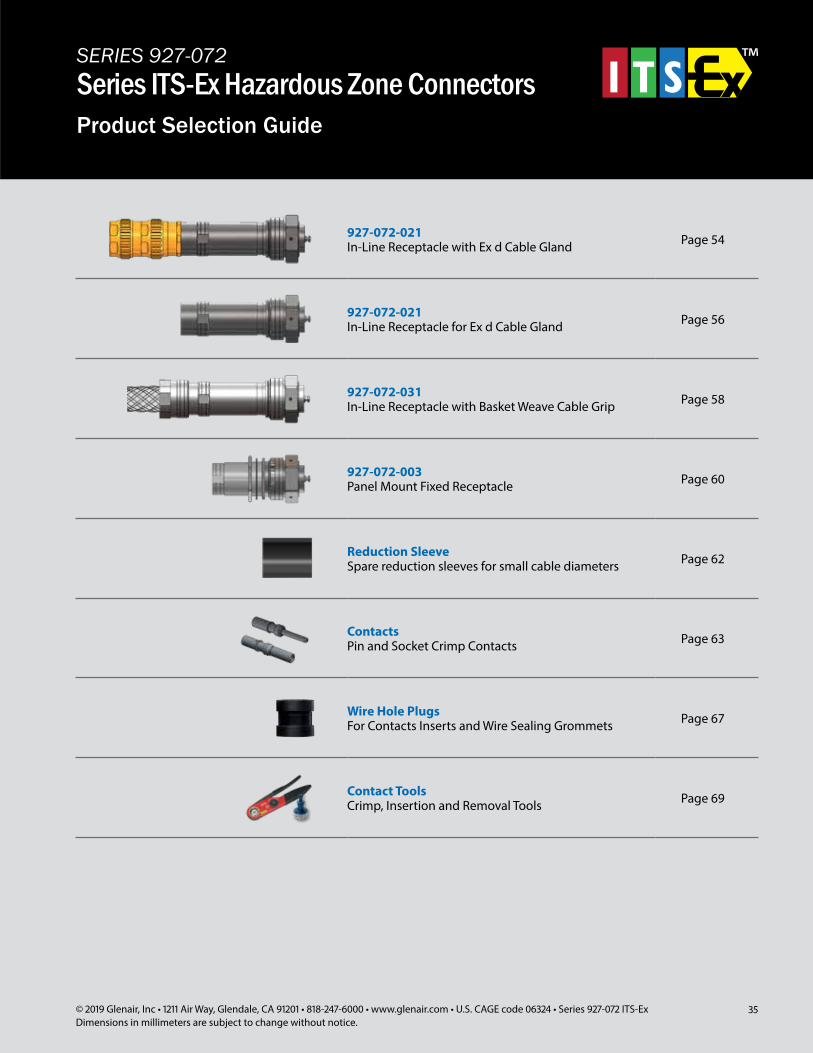
927-072-021 In-Line Receptacle with Ex d Cable Gland Page 54
927-072-021 In-Line Receptacle for Ex d Cable Gland Page 56
927-072-031 In-Line Receptacle with Basket Weave Cable Grip Page 58
927-072-003 Panel Mount Fixed Receptacle Page 60
Reduction Sleeve Spare reduction sleeves for small cable diameters Page 62
Contacts Pin and Socket Crimp Contacts Page 63
Wire Hole Plugs For Contacts Inserts and Wire Sealing Grommets Page 67
Contact Tools Crimp, Insertion and Removal Tools Page 69
36 © 2019 Glenair, Inc • 1211 Air Way, Glendale, CA 91201 • 818-247-6000 • www.glenair.com • U.S. CAGE code 06324 • Series 927-072 ITS-ExDimensions in millimeters are subject to change without notice.
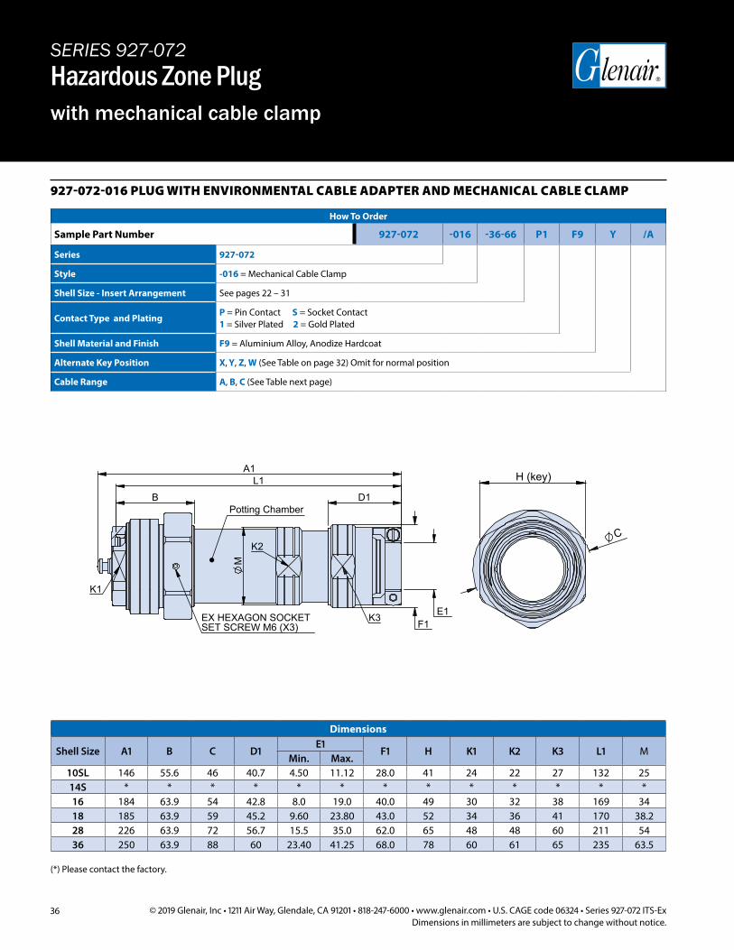
927-072-016 PLUG WITH ENVIRONMENTAL CABLE ADAPTER AND MECHANICAL CABLE CLAMP
How To Order
Sample Part Number 927-072 -016 -36-66 P1 F9 Y /A
Series 927-072
Style -016 = Mechanical Cable Clamp
Shell Size - Insert Arrangement See pages 22 – 31
Contact Type and PlatingP = Pin Contact S = Socket Contact1 = Silver Plated 2 = Gold Plated
Shell Material and Finish F9 = Aluminium Alloy, Anodize Hardcoat
Alternate Key Position X, Y, Z, W (See Table on page 32) Omit for normal position
Cable Range A, B, C (See Table next page)
E1
A1
K1
K2
K3SET SCREW M6 (X3)
Potting Chamber
EX HEXAGON SOCKET
D1 B
F1
L1
M
H (key)
C
Dimensions
Shell Size A1 B C D1E1
F1 H K1 K2 K3 L1 MMin. Max.
10SL 146 55.6 46 40.7 4.50 11.12 28.0 41 24 22 27 132 2514S * * * * * * * * * * * * *16 184 63.9 54 42.8 8.0 19.0 40.0 49 30 32 38 169 3418 185 63.9 59 45.2 9.60 23.80 43.0 52 34 36 41 170 38.228 226 63.9 72 56.7 15.5 35.0 62.0 65 48 48 60 211 5436 250 63.9 88 60 23.40 41.25 68.0 78 60 61 65 235 63.5
SERIES 927-072Hazardous Zone Plugwith mechanical cable clamp
(*) Please contact the factory.
37© 2019 Glenair, Inc • 1211 Air Way, Glendale, CA 91201 • 818-247-6000 • www.glenair.com • U.S. CAGE code 06324 • Series 927-072 ITS-ExDimensions in millimeters are subject to change without notice.
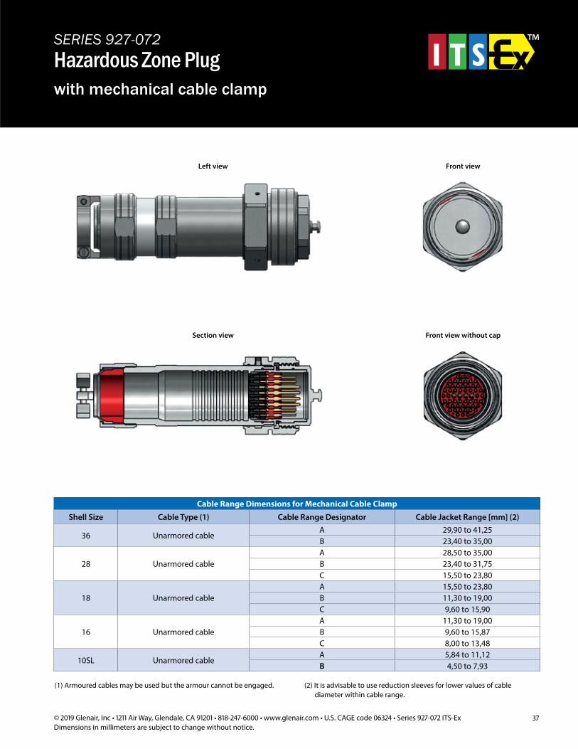
SERIES 927-072Hazardous Zone Plugwith mechanical cable clamp
Cable Range Dimensions for Mechanical Cable Clamp
Shell Size Cable Type (1) Cable Range Designator Cable Jacket Range [mm] (2)
36 Unarmored cableA 29,90 to 41,25B 23,40 to 35,00
28 Unarmored cableA 28,50 to 35,00B 23,40 to 31,75C 15,50 to 23,80
18 Unarmored cableA 15,50 to 23,80B 11,30 to 19,00C 9,60 to 15,90
16 Unarmored cableA 11,30 to 19,00B 9,60 to 15,87C 8,00 to 13,48
10SL Unarmored cableA 5,84 to 11,12B 4,50 to 7,93
(1) Armoured cables may be used but the armour cannot be engaged. (2) It is advisable to use reduction sleeves for lower values of cable diameter within cable range.
Left view Front view
Section view Front view without cap
38 © 2019 Glenair, Inc • 1211 Air Way, Glendale, CA 91201 • 818-247-6000 • www.glenair.com • U.S. CAGE code 06324 • Series 927-072 ITS-ExDimensions in millimeters are subject to change without notice.
SERIES 927-072Hazardous Zone Plugwith Ex cable gland
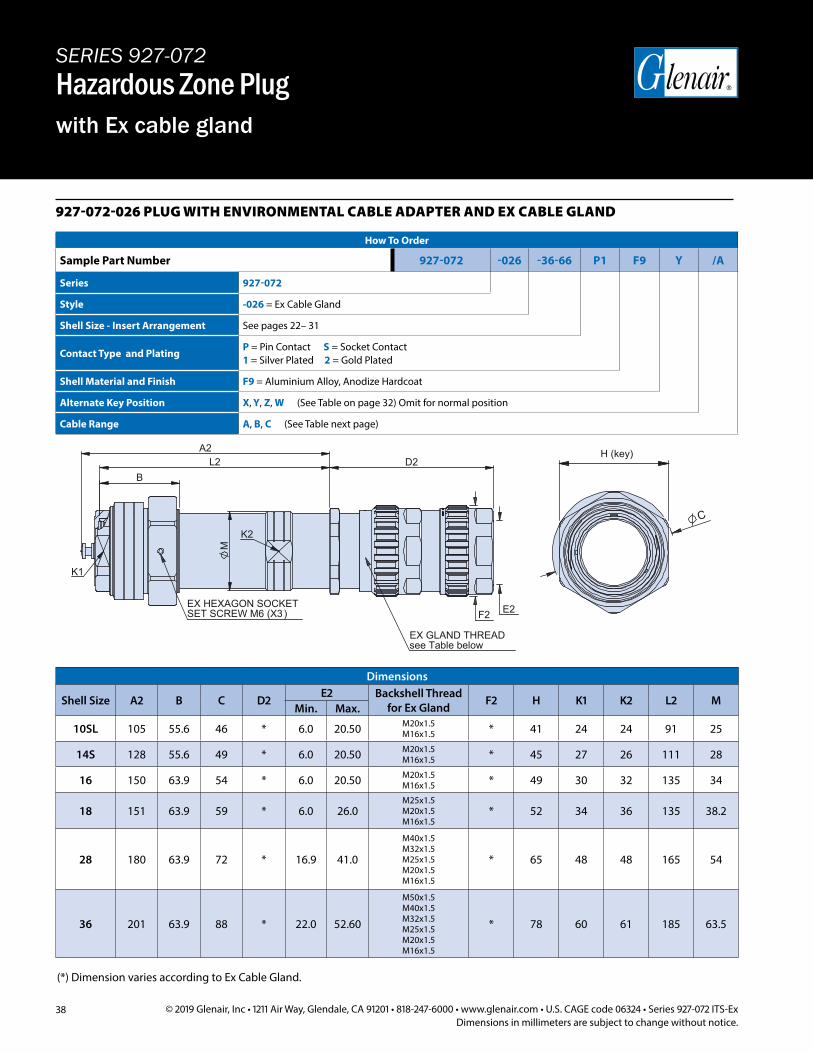
927-072-026 PLUG WITH ENVIRONMENTAL CABLE ADAPTER AND EX CABLE GLAND
How To Order
Sample Part Number 927-072 -026 -36-66 P1 F9 Y /A
Series 927-072
Style -026 = Ex Cable Gland
Shell Size - Insert Arrangement See pages 22– 31
Contact Type and PlatingP = Pin Contact S = Socket Contact1 = Silver Plated 2 = Gold Plated
Shell Material and Finish F9 = Aluminium Alloy, Anodize Hardcoat
Alternate Key Position X, Y, Z, W (See Table on page 32) Omit for normal position
Cable Range A, B, C (See Table next page)
A2
E2
see Table below
K2
SET SCREW M6 (X3)
K1
EX HEXAGON SOCKET
EX GLAND THREAD
B
F2
D2 L2
M
C
H (key)
Dimensions
Shell Size A2 B C D2E2 Backshell Thread
for Ex Gland F2 H K1 K2 L2 MMin. Max.
10SL 105 55.6 46 * 6.0 20.50 M20x1.5 M16x1.5 * 41 24 24 91 25
14S 128 55.6 49 * 6.0 20.50 M20x1.5 M16x1.5 * 45 27 26 111 28
16 150 63.9 54 * 6.0 20.50 M20x1.5 M16x1.5 * 49 30 32 135 34
18 151 63.9 59 * 6.0 26.0M25x1.5 M20x1.5M16x1.5
* 52 34 36 135 38.2
28 180 63.9 72 * 16.9 41.0
M40x1.5 M32x1.5 M25x1.5 M20x1.5 M16x1.5
* 65 48 48 165 54
36 201 63.9 88 * 22.0 52.60
M50x1.5 M40x1.5 M32x1.5 M25x1.5 M20x1.5 M16x1.5
* 78 60 61 185 63.5
(*) Dimension varies according to Ex Cable Gland.
39© 2019 Glenair, Inc • 1211 Air Way, Glendale, CA 91201 • 818-247-6000 • www.glenair.com • U.S. CAGE code 06324 • Series 927-072 ITS-ExDimensions in millimeters are subject to change without notice.
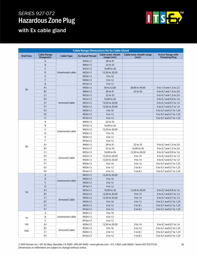
Cable Range Dimensions for Ex Cable Gland
Shell Size Cable Range Designator Cable Type Ex Gland Thread Cable outer sheath
range [mm]Cable inner sheath range
[mm]Armor Range with
Clamping Ring
36
A
Unarmored cable
M50x1.5 28 to 41B M40x1.5 22 to 33C M32x1.5 16,90 to 26D M25x1.5 12,50 to 20,50E M20x1.5 9 to 16F M20x1.5 6 to 12G M16x1.5 6 to 12
A1
Armored Cable
M50x1.5 36 to 52,60 28,90 to 44,40 0 to 1,0 and 1,5 to 2,5B1 M40x1.5 28 to 41 22 to 33 0 to 0,7 and 1,3 to 2,0C1 M32x1.5 22 to 33 0 to 0,7 and 1,3 to 2,0D1 M25x1.5 16,90 to 26 0 to 0,7 and 0,9 to 1,6E1 M25x1.5 12,50 to 20,50 0 to 0,7 and 0,7 to 1,4F1 M20x1.5 12,50 to 20,50 0 to 0,7 and 0,7 to 1,4G1 M20x1.5 9 to 16 0 to 0,7 and 0,7 to 1,25H1 M20x1.5 6 to 12 0 to 0,7 and 0,7 to 1,25I1 M16x1.5 6 to 12 0 to 0,7 and 0,7 to 1,25
28
A
Unarmored cable
M40x1.5 22 to 33B M32x1.5 16,90 to 26C M25x1.5 12,50 to 20,50D M20x1.5 9 to 16E M20x1.5 6 to 12F M16x1.5 6 to 12
A1
Armored Cable
M40x1.5 28 to 41 22 to 33 0 to 0,7 and 1,3 to 2,0B1 M32x1.5 22 to 33 16,90 to 26 0 to 0,7 and 1,3 to 2,0C1 M25x1.5 16,90 to 26 12,50 to 20,50 0 to 0,7 and 0,9 to 1,6D1 M25x1.5 12,50 to 20,50 9 to 14 0 to 0,7 and 0,7 to 1,4E1 M20x1.5 12,50 to 20,50 9 to 14 0 to 0,7 and 0,7 to 1,4F1 M20x1.5 9 to 16 6 to 12 0 to 0,7 and 0,7 to 1,25G1 M20x1.5 6 to 12 3 to 8,1 0 to 0,7 and 0,7 to 1,25H1 M16x1.5 6 to 12 3 to 8,1 0 to 0,7 and 0,7 to 1,25
18
A
Unarmored cable
M25x1.5 12,50 to 20,50B M20x1.5 9 to 16C M20x1.5 6 to 12D M16x1.5 6 to 12
A1
Armored Cable
M25x1.5 16,90 to 26 12,50 to 20,50 0 to 0,7 and 0,9 to 1,6B1 M25x1.5 12,50 to 20,50 9 to 14 0 to 0,7 and 0,7 to 1,4C1 M20x1.5 12,50 to 20,50 9 to 14 0 to 0,7 and 0,7 to 1,4D1 M20x1.5 9 to 16 6 to 12 0 to 0,7 and 0,7 to 1,25E1 M20x1.5 6 to 12 3 to 8,1 0 to 0,7 and 0,7 to 1,25F1 M16x1.5 6 to 12 3 to 8,1 0 to 0,7 and 0,7 to 1,25
16
14S
10SL
AUnarmored cable
M20x1.5 9 to 16B M20x1.5 6 to 12C M16x1.5 6 to 12
A1
Armored Cable
M20x1.5 12,50 to 20,50 9 to 14 0 to 0,7 and 0,7 to 1,4B1 M20x1.5 9 to 16 6 to 12 0 to 0,7 and 0,7 to 1,25C1 M20x1.5 6 to 12 3 to 8,1 0 to 0,7 and 0,7 to 1,25D1 M16x1.5 6 to 12 3 to 8,1 0 to 0,7 and 0,7 to 1,25
SERIES 927-072Hazardous Zone Plugwith Ex cable gland
40 © 2019 Glenair, Inc • 1211 Air Way, Glendale, CA 91201 • 818-247-6000 • www.glenair.com • U.S. CAGE code 06324 • Series 927-072 ITS-ExDimensions in millimeters are subject to change without notice.
SERIES 927-072Hazardous Zone Plugfor Ex cable gland
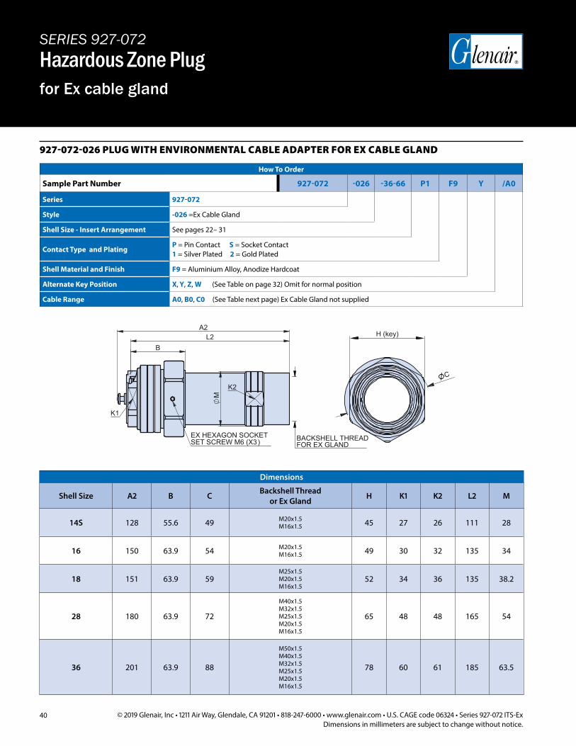
927-072-026 PLUG WITH ENVIRONMENTAL CABLE ADAPTER FOR EX CABLE GLAND
How To Order
Sample Part Number 927-072 -026 -36-66 P1 F9 Y /A0
Series 927-072
Style -026 =Ex Cable Gland
Shell Size - Insert Arrangement See pages 22– 31
Contact Type and PlatingP = Pin Contact S = Socket Contact1 = Silver Plated 2 = Gold Plated
Shell Material and Finish F9 = Aluminium Alloy, Anodize Hardcoat
Alternate Key Position X, Y, Z, W (See Table on page 32) Omit for normal position
Cable Range A0, B0, C0 (See Table next page) Ex Cable Gland not supplied
Dimensions
Shell Size A2 B C Backshell Thread or Ex Gland H K1 K2 L2 M
14S 128 55.6 49 M20x1.5 M16x1.5 45 27 26 111 28
16 150 63.9 54 M20x1.5 M16x1.5 49 30 32 135 34
18 151 63.9 59M25x1.5 M20x1.5 M16x1.5
52 34 36 135 38.2
28 180 63.9 72
M40x1.5 M32x1.5 M25x1.5 M20x1.5 M16x1.5
65 48 48 165 54
36 201 63.9 88
M50x1.5 M40x1.5 M32x1.5 M25x1.5 M20x1.5 M16x1.5
78 60 61 185 63.5
40 © 2017 Glenair, Inc • 1211 Air Way, Glendale, CA 91201 • 818-247-6000 • www.glenair.com • U.S. CAGE code 06324 • Series 927-072 ITS-ExDimensions in millimeters are subject to change without notice.
927-072-026 PLUG WITH ENVIRONMENTAL CABLE ADAPTER FOR EX CABLE GLAND
How To Order
Sample Part Number 927-072 -026 -36-66 P1 F9 Y /A0
Series 927-072
Style -026 = Ex Cable Gland
Shell Size - Insert Arrangement See pages 22– 31
Contact Type and PlatingP = Pin Contact, S = Socket Contact1 = Silver Plated, 2 = Gold Plated
Shell Material and Finish F9 = Aluminium Alloy, Anodize Hardcoat
Alternate Key Position X, Y, Z, W (See Table on page 32) Omit for normal position
Cable Range A0, B0, C0 (See Table next page) Ex Cable Gland not supplied
DimensionsShell Size A2 B C Backshell Thread
for Ex Gland H K1 K2 L2 M
10SL 105 55.6 46 M20x1.5M16x1.5 41 24 24 91 25
14S 128 55.6 49 M20x1.5M16x1.5 45 27 26 111 28
16 150 63.9 54 M20x1.5M16x1.5 49 30 32 135 34
18 151 63.9 59M25x1.5M20x1.5M16x1.5
52 34 36 135 38.2
28 180 63.9 72
M40x1.5M32x1.5M25x1.5M20x1.5M16x1.5
65 48 48 165 54
36 201 63.9 88
M50x1.5M40x1.5M32x1.5M25x1.5M20x1.5M16x1.5
78 60 61 185 63.5
SERIES 927-072Hazardous Zone Plugfor Ex cable gland
A2
C
K2
SET SCREW M6 (X3)
K1
EX HEXAGON SOCKET
B L2
M
H (key)
BACKSHELL THREADFOR EX GLAND
41© 2019 Glenair, Inc • 1211 Air Way, Glendale, CA 91201 • 818-247-6000 • www.glenair.com • U.S. CAGE code 06324 • Series 927-072 ITS-ExDimensions in millimeters are subject to change without notice.
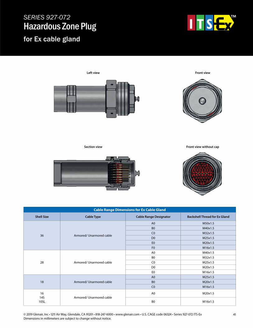
SERIES 927-072Hazardous Zone Plugfor Ex cable gland
Cable Range Dimensions for Ex Cable Gland
Shell Size Cable Type Cable Range Designator Backshell Thread for Ex Gland
36 Armored/ Unarmored cable
A0 M50x1.5B0 M40x1.5C0 M32x1.5D0 M25x1.5E0 M20x1.5F0 M16x1.5
28 Armored/ Unarmored cable
A0 M40x1.5B0 M32x1.5C0 M25x1.5D0 M20x1.5E0 M16x1.5
18 Armored/ Unarmored cableA0 M25x1.5B0 M20x1.5C0 M16x1.5
1614S
10SLArmored/ Unarmored cable
A0 M20x1.5
B0 M16x1.5
41© 2017 Glenair, Inc • 1211 Air Way, Glendale, CA 91201 • 818-247-6000 • www.glenair.com • U.S. CAGE code 06324 • Series 927-072 ITS-ExDimensions in millimeters are subject to change without notice.
Cable Range Dimensions for Ex Cable Gland
Shell Size Cable TypeCable Range Designator
Backshell Thread for Ex Gland
36Armored/
Unarmored cable
A0 M50x1.5B0 M40x1.5C0 M32x1.5D0 M25x1.5E0 M20x1.5F0 M16x1.5
28Armored/
Unarmored cable
A0 M40x1.5B0 M32x1.5C0 M25x1.5D0 M20x1.5E0 M16x1.5
18Armored/
Unarmored cable
A0 M25x1.5B0 M20x1.5C0 M16x1.5
1614S
10SL
Armored/Unarmored cable
A0 M20x1.5
B0 M16x1.5
SERIES 927-072Hazardous Zone Plugfor Ex cable gland
Section view Front view without cap
Left view Front view
Left view Front view
Section view Front view without cap
42 © 2019 Glenair, Inc • 1211 Air Way, Glendale, CA 91201 • 818-247-6000 • www.glenair.com • U.S. CAGE code 06324 • Series 927-072 ITS-ExDimensions in millimeters are subject to change without notice.
SERIES 927-072Hazardous Zone Plugwith basket weave cable grip
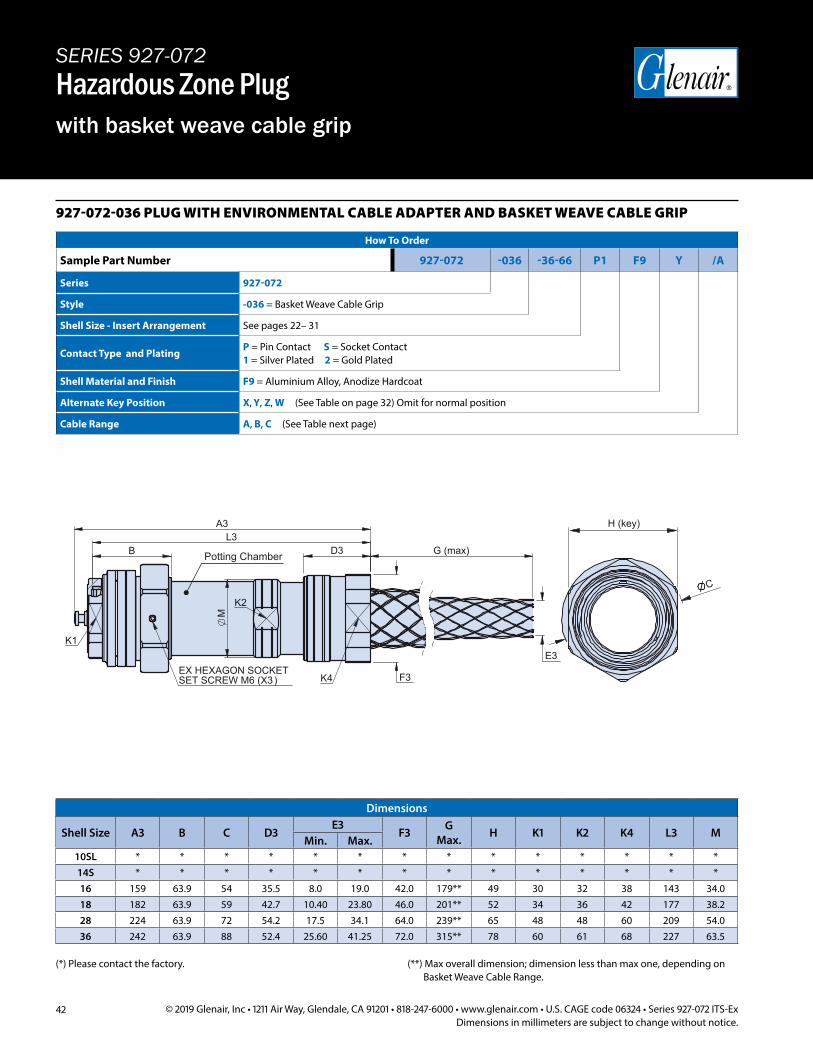
927-072-036 PLUG WITH ENVIRONMENTAL CABLE ADAPTER AND BASKET WEAVE CABLE GRIP
How To Order
Sample Part Number 927-072 -036 -36-66 P1 F9 Y /A
Series 927-072
Style -036 = Basket Weave Cable Grip
Shell Size - Insert Arrangement See pages 22– 31
Contact Type and PlatingP = Pin Contact S = Socket Contact1 = Silver Plated 2 = Gold Plated
Shell Material and Finish F9 = Aluminium Alloy, Anodize Hardcoat
Alternate Key Position X, Y, Z, W (See Table on page 32) Omit for normal position
Cable Range A, B, C (See Table next page)
Dimensions
Shell Size A3 B C D3E3
F3 G Max. H K1 K2 K4 L3 M
Min. Max.10SL * * * * * * * * * * * * * *14S * * * * * * * * * * * * * *16 159 63.9 54 35.5 8.0 19.0 42.0 179** 49 30 32 38 143 34.018 182 63.9 59 42.7 10.40 23.80 46.0 201** 52 34 36 42 177 38.2 28 224 63.9 72 54.2 17.5 34.1 64.0 239** 65 48 48 60 209 54.036 242 63.9 88 52.4 25.60 41.25 72.0 315** 78 60 61 68 227 63.5
(*) Please contact the factory. (**) Max overall dimension; dimension less than max one, depending on Basket Weave Cable Range.
K1
K2
K4SET SCREW M6 (X3)EX HEXAGON SOCKET
D3 B
F3
L3
M
A3
E3
G (max)
H (key)
C
Potting Chamber
43© 2019 Glenair, Inc • 1211 Air Way, Glendale, CA 91201 • 818-247-6000 • www.glenair.com • U.S. CAGE code 06324 • Series 927-072 ITS-ExDimensions in millimeters are subject to change without notice.
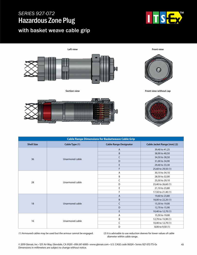
SERIES 927-072Hazardous Zone Plugwith basket weave cable grip
Cable Range Dimensions for Basketweave Cable Grip
Shell Size Cable Type (1) Cable Range Designator Cable Jacket Range [mm] (2)
36 Unarmored cable
A 39,40 to 41,25B 38,90 to 40,50C 34,50 to 38,50D 31,00 to 34,90E 29,40 to 33,30F 25,60 to 29,50 (1)
28 Unarmored cable
A 30,10 to 34,10B 28,50 to 32,00C 25,50 to 29,10D 23,40 to 26,60 (1)E 21,10 to 23,80F 17,50 to 21,40 (1)
18 Unarmored cable
A 19,60 to 23,80B 18,00 to 22,20 (1)C 15,50 to 19,00D 12,70 to 15,90E 10,40 to 12,70 (1)
16 Unarmored cable
A 15,50 to 19,00B 12,70 to 15,90 (1)C 10,40 to 12,70 (1)D 8,00 to 9,50 (1)
(1) Armoured cables may be used but the armour cannot be engaged. (2) It is advisable to use reduction sleeves for lower values of cable diameter within cable range.
Left view Front view
Section view Front view without cap
44 © 2019 Glenair, Inc • 1211 Air Way, Glendale, CA 91201 • 818-247-6000 • www.glenair.com • U.S. CAGE code 06324 • Series 927-072 ITS-ExDimensions in millimeters are subject to change without notice.
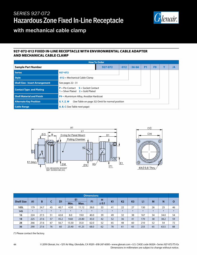
SERIES 927-072Hazardous Zone Fixed In-Line Receptaclewith mechanical cable clamp
927-072-012 FIXED IN-LINE RECEPTACLE WITH ENVIRONMENTAL CABLE ADAPTER AND MECHANICAL CABLE CLAMP
How To Order
Sample Part Number 927-072 -012 -36-66 P1 F9 Y /A
Series 927-072
Style -012 = Mechanical Cable Clamp
Shell Size - Insert Arrangement See pages 22– 31
Contact Type and PlatingP = Pin Contact S = Socket Contact1 = Silver Plated 2 = Gold Plated
Shell Material and Finish F9 = Aluminium Alloy, Anodize Hardcoat
Alternate Key Position X, Y, Z, W (See Table on page 32) Omit for normal position
Cable Range A, B, C (See Table next page)
E1
O-ring for Panel Mount
K1 (key)
K2
SET SCREW M6 (X3)EX HEXAGON SOCKET
K3
L1 A1
N M
O B D1
F1
C
H
5,6 Thru 4X
Potting Chamber
Dimensions
Shell Size A1 B C D1E1
F1 H ± 0.1 K1 K2 K3 L1 M N O
Min. Max.10SL 179 24.7 45 40.7 4.50 11.12 28.0 33 41 22 27 130 26 25 4614S * * * * * * * * * * * * * * *16 224 27.5 51 42.8 8.0 19.0 40.0 39 49 32 38 167 34 34.0 5418 225 27.6 57 45.2 9.60 23.80 43.0 42 52 36 41 170 38 38.2 5928 266 27.6 67 56.7 15.50 35.0 62.0 52 65 48 60 210 52 54 7236 290 27.6 76 60 23.40 41.25 68.0 62 78 61 65 233 65 63.5 88
(*) Please contact the factory.
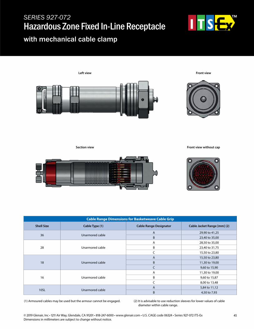
45© 2019 Glenair, Inc • 1211 Air Way, Glendale, CA 91201 • 818-247-6000 • www.glenair.com • U.S. CAGE code 06324 • Series 927-072 ITS-ExDimensions in millimeters are subject to change without notice.
SERIES 927-072Hazardous Zone Fixed In-Line Receptaclewith mechanical cable clamp
Cable Range Dimensions for Basketweave Cable Grip
Shell Size Cable Type (1) Cable Range Designator Cable Jacket Range [mm] (2)
36 Unarmored cableA 29,90 to 41,25B 23,40 to 35,00
28 Unarmored cableA 28,50 to 35,00B 23,40 to 31,75C 15,50 to 23,80
18 Unarmored cableA 15,50 to 23,80B 11,30 to 19,00C 9,60 to 15,90
16 Unarmored cableA 11,30 to 19,00B 9,60 to 15,87C 8,00 to 13,48
10SL Unarmored cableA 5,84 to 11,12B 4,50 to 7,93
(1) Armoured cables may be used but the armour cannot be engaged. (2) It is advisable to use reduction sleeves for lower values of cable diameter within cable range.
Left view Front view
Section view Front view without cap
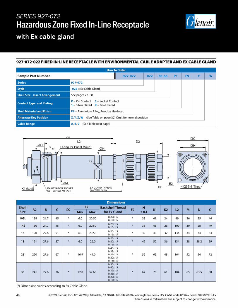
46 © 2019 Glenair, Inc • 1211 Air Way, Glendale, CA 91201 • 818-247-6000 • www.glenair.com • U.S. CAGE code 06324 • Series 927-072 ITS-ExDimensions in millimeters are subject to change without notice.
927-072-022 FIXED IN-LINE RECEPTACLE WITH ENVIRONMENTAL CABLE ADAPTER AND EX CABLE GLAND
How To Order
Sample Part Number 927-072 -022 -36-66 P1 F9 Y /A
Series 927-072
Style -022 = Ex Cable Gland
Shell Size - Insert Arrangement See pages 22– 31
Contact Type and PlatingP = Pin Contact S = Socket Contact1 = Silver Plated 2 = Gold Plated
Shell Material and Finish F9 = Aluminium Alloy, Anodize Hardcoat
Alternate Key Position X, Y, Z, W (See Table on page 32) Omit for normal position
Cable Range A, B, C (See Table next page)
C
H
A2
E2 K1 (key)
O-ring for Panel Mount
EX GLAND THREADsee Table belowSET SCREW M6 (X3)
EX HEXAGON SOCKET
K2
D2
B
F2
L2 O
N
M 5,6 Thru 4XØ
(*) Dimension varies according to Ex Cable Gland.
DimensionsShell Size A2 B C D2
E2 Backshell Thread for Ex Gland F2 H
± 0.1 K1 K2 L2 M N OMin. Max.
10SL 138 24.7 45 * 6.0 20.50 M20x1.5 M16x1.5 * 33 41 24 89 26 25 46
14S 160 24.7 45 * 6.0 20.50 M20x1.5 M16x1.5 * 33 45 26 109 30 28 49
16 190 27.6 51 * 6.0 20.50 M20x1.5 M16x1.5 * 39 49 32 134 34 34 54
18 191 27.6 57 * 6.0 26.0M25x1.5 M20x1.5 M16x1.5
* 42 52 36 134 38 38.2 59
28 220 27.6 67 * 16.9 41.0
M40x1.5 M32x1.5 M25x1.5 M20x1.5 M16x1.5
* 52 65 48 164 52 54 72
36 241 27.6 76 * 22.0 52.60
M50x1.5 M40x1.5 M32x1.5 M25x1.5 M20x1.5 M16x1.5
* 62 78 61 184 65 63.5 88
SERIES 927-072Hazardous Zone Fixed In-Line Receptaclewith Ex cable gland
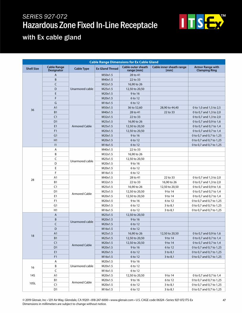
47© 2019 Glenair, Inc • 1211 Air Way, Glendale, CA 91201 • 818-247-6000 • www.glenair.com • U.S. CAGE code 06324 • Series 927-072 ITS-ExDimensions in millimeters are subject to change without notice.
Cable Range Dimensions for Ex Cable Gland
Shell Size Cable Range Designator Cable Type Ex Gland Thread Cable outer sheath
range [mm]Cable inner sheath range
[mm]Armor Range with
Clamping Ring
36
A
Unarmored cable
M50x1.5 28 to 41B M40x1.5 22 to 33C M32x1.5 16,90 to 26D M25x1.5 12,50 to 20,50E M20x1.5 9 to 16F M20x1.5 6 to 12G M16x1.5 6 to 12
A1
Armored Cable
M50x1.5 36 to 52,60 28,90 to 44,40 0 to 1,0 and 1,5 to 2,5B1 M40x1.5 28 to 41 22 to 33 0 to 0,7 and 1,3 to 2,0C1 M32x1.5 22 to 33 0 to 0,7 and 1,3 to 2,0D1 M25x1.5 16,90 to 26 0 to 0,7 and 0,9 to 1,6E1 M25x1.5 12,50 to 20,50 0 to 0,7 and 0,7 to 1,4F1 M20x1.5 12,50 to 20,50 0 to 0,7 and 0,7 to 1,4G1 M20x1.5 9 to 16 0 to 0,7 and 0,7 to 1,25H1 M20x1.5 6 to 12 0 to 0,7 and 0,7 to 1,25I1 M16x1.5 6 to 12 0 to 0,7 and 0,7 to 1,25
28
A
Unarmored cable
M40x1.5 22 to 33B M32x1.5 16,90 to 26C M25x1.5 12,50 to 20,50D M20x1.5 9 to 16E M20x1.5 6 to 12F M16x1.5 6 to 12
A1
Armored Cable
M40x1.5 28 to 41 22 to 33 0 to 0,7 and 1,3 to 2,0B1 M32x1.5 22 to 33 16,90 to 26 0 to 0,7 and 1,3 to 2,0C1 M25x1.5 16,90 to 26 12,50 to 20,50 0 to 0,7 and 0,9 to 1,6D1 M25x1.5 12,50 to 20,50 9 to 14 0 to 0,7 and 0,7 to 1,4E1 M20x1.5 12,50 to 20,50 9 to 14 0 to 0,7 and 0,7 to 1,4F1 M20x1.5 9 to 16 6 to 12 0 to 0,7 and 0,7 to 1,25G1 M20x1.5 6 to 12 3 to 8,1 0 to 0,7 and 0,7 to 1,25H1 M16x1.5 6 to 12 3 to 8,1 0 to 0,7 and 0,7 to 1,25
18
A
Unarmored cable
M25x1.5 12,50 to 20,50B M20x1.5 9 to 16C M20x1.5 6 to 12D M16x1.5 6 to 12
A1
Armored Cable
M25x1.5 16,90 to 26 12,50 to 20,50 0 to 0,7 and 0,9 to 1,6B1 M25x1.5 12,50 to 20,50 9 to 14 0 to 0,7 and 0,7 to 1,4C1 M20x1.5 12,50 to 20,50 9 to 14 0 to 0,7 and 0,7 to 1,4D1 M20x1.5 9 to 16 6 to 12 0 to 0,7 and 0,7 to 1,25E1 M20x1.5 6 to 12 3 to 8,1 0 to 0,7 and 0,7 to 1,25F1 M16x1.5 6 to 12 3 to 8,1 0 to 0,7 and 0,7 to 1,25
16
14S
10SL
AUnarmored cable
M20x1.5 9 to 16B M20x1.5 6 to 12C M16x1.5 6 to 12
A1
Armored Cable
M20x1.5 12,50 to 20,50 9 to 14 0 to 0,7 and 0,7 to 1,4B1 M20x1.5 9 to 16 6 to 12 0 to 0,7 and 0,7 to 1,25C1 M20x1.5 6 to 12 3 to 8,1 0 to 0,7 and 0,7 to 1,25D1 M16x1.5 6 to 12 3 to 8,1 0 to 0,7 and 0,7 to 1,25
SERIES 927-072Hazardous Zone Fixed In-Line Receptaclewith Ex cable gland
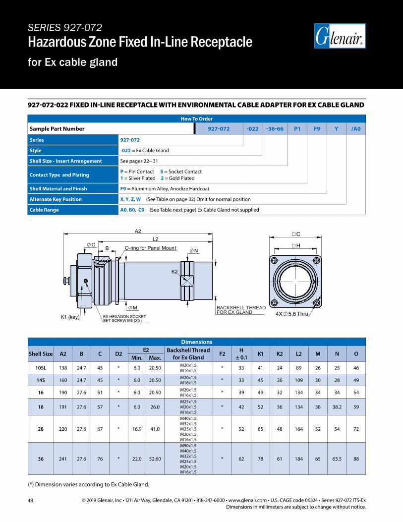
48 © 2019 Glenair, Inc • 1211 Air Way, Glendale, CA 91201 • 818-247-6000 • www.glenair.com • U.S. CAGE code 06324 • Series 927-072 ITS-ExDimensions in millimeters are subject to change without notice.
927-072-022 FIXED IN-LINE RECEPTACLE WITH ENVIRONMENTAL CABLE ADAPTER FOR EX CABLE GLAND
How To Order
Sample Part Number 927-072 -022 -36-66 P1 F9 Y /A0
Series 927-072
Style -022 = Ex Cable Gland
Shell Size - Insert Arrangement See pages 22– 31
Contact Type and PlatingP = Pin Contact S = Socket Contact1 = Silver Plated 2 = Gold Plated
Shell Material and Finish F9 = Aluminium Alloy, Anodize Hardcoat
Alternate Key Position X, Y, Z, W (See Table on page 32) Omit for normal position
Cable Range A0, B0, C0 (See Table next page) Ex Cable Gland not supplied
(*) Dimension varies according to Ex Cable Gland.
Dimensions
Shell Size A2 B C D2E2 Backshell Thread
for Ex Gland F2 H ± 0.1 K1 K2 L2 M N O
Min. Max.
10SL 138 24.7 45 * 6.0 20.50 M20x1.5 M16x1.5 * 33 41 24 89 26 25 46
14S 160 24.7 45 * 6.0 20.50 M20x1.5 M16x1.5 * 33 45 26 109 30 28 49
16 190 27.6 51 * 6.0 20.50 M20x1.5 M16x1.5 * 39 49 32 134 34 34 54
18 191 27.6 57 * 6.0 26.0M25x1.5 M20x1.5 M16x1.5
* 42 52 36 134 38 38.2 59
28 220 27.6 67 * 16.9 41.0
M40x1.5 M32x1.5 M25x1.5 M20x1.5 M16x1.5
* 52 65 48 164 52 54 72
36 241 27.6 76 * 22.0 52.60
M50x1.5 M40x1.5 M32x1.5 M25x1.5 M20x1.5 M16x1.5
* 62 78 61 184 65 63.5 88
SERIES 927-072Hazardous Zone Fixed In-Line Receptaclefor Ex cable gland
C
H
A2
K1 (key)
O-ring for Panel Mount
SET SCREW M6 (X3)EX HEXAGON SOCKET
K2
B
L2 O
N
M 5,64X Thru
BACKSHELL THREADFOR EX GLAND
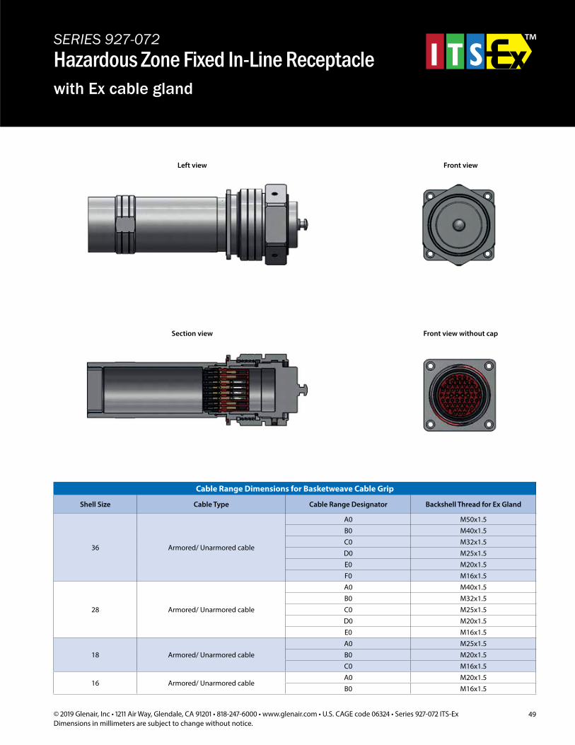
49© 2019 Glenair, Inc • 1211 Air Way, Glendale, CA 91201 • 818-247-6000 • www.glenair.com • U.S. CAGE code 06324 • Series 927-072 ITS-ExDimensions in millimeters are subject to change without notice.
SERIES 927-072Hazardous Zone Fixed In-Line Receptaclewith Ex cable gland
Left view Front view
Section view Front view without cap
Cable Range Dimensions for Basketweave Cable Grip
Shell Size Cable Type Cable Range Designator Backshell Thread for Ex Gland
36 Armored/ Unarmored cable
A0 M50x1.5B0 M40x1.5C0 M32x1.5D0 M25x1.5E0 M20x1.5F0 M16x1.5
28 Armored/ Unarmored cable
A0 M40x1.5B0 M32x1.5C0 M25x1.5D0 M20x1.5E0 M16x1.5
18 Armored/ Unarmored cableA0 M25x1.5B0 M20x1.5C0 M16x1.5
16 Armored/ Unarmored cableA0 M20x1.5B0 M16x1.5
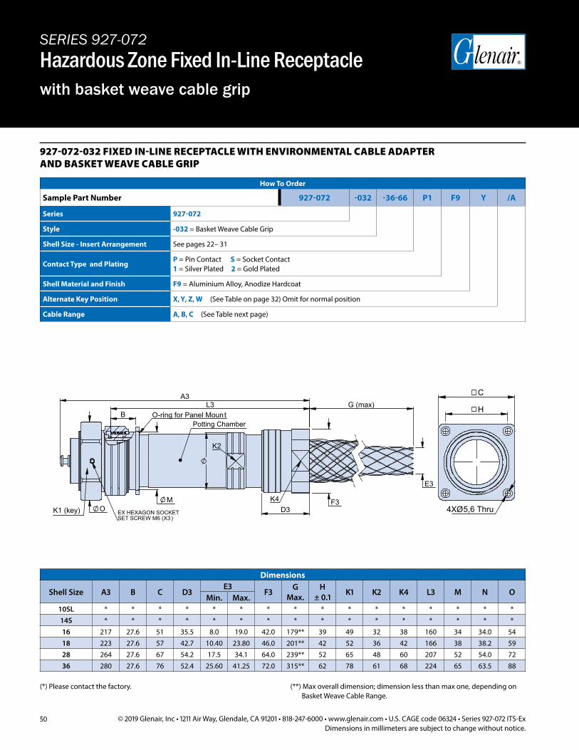
50 © 2019 Glenair, Inc • 1211 Air Way, Glendale, CA 91201 • 818-247-6000 • www.glenair.com • U.S. CAGE code 06324 • Series 927-072 ITS-ExDimensions in millimeters are subject to change without notice.
SERIES 927-072Hazardous Zone Fixed In-Line Receptaclewith basket weave cable grip
927-072-032 FIXED IN-LINE RECEPTACLE WITH ENVIRONMENTAL CABLE ADAPTER AND BASKET WEAVE CABLE GRIP
How To Order
Sample Part Number 927-072 -032 -36-66 P1 F9 Y /A
Series 927-072
Style -032 = Basket Weave Cable Grip
Shell Size - Insert Arrangement See pages 22– 31
Contact Type and PlatingP = Pin Contact S = Socket Contact1 = Silver Plated 2 = Gold Plated
Shell Material and Finish F9 = Aluminium Alloy, Anodize Hardcoat
Alternate Key Position X, Y, Z, W (See Table on page 32) Omit for normal position
Cable Range A, B, C (See Table next page)
C
H
5,6 Thru
O-ring for Panel Mount
K1 (key)
K2
SET SCREW M6 (X3)EX HEXAGON SOCKET
K4
L3
O M
B
D3 F3
G (max)
E3
A3
4XØ
Potting Chamber
Dimensions
Shell Size A3 B C D3E3
F3 G Max.
H ± 0.1 K1 K2 K4 L3 M N O
Min. Max.10SL * * * * * * * * * * * * * * * *14S * * * * * * * * * * * * * * * *16 217 27.6 51 35.5 8.0 19.0 42.0 179** 39 49 32 38 160 34 34.0 5418 223 27.6 57 42.7 10.40 23.80 46.0 201** 42 52 36 42 166 38 38.2 5928 264 27.6 67 54.2 17.5 34.1 64.0 239** 52 65 48 60 207 52 54.0 7236 280 27.6 76 52.4 25.60 41.25 72.0 315** 62 78 61 68 224 65 63.5 88
(*) Please contact the factory. (**) Max overall dimension; dimension less than max one, depending on Basket Weave Cable Range.
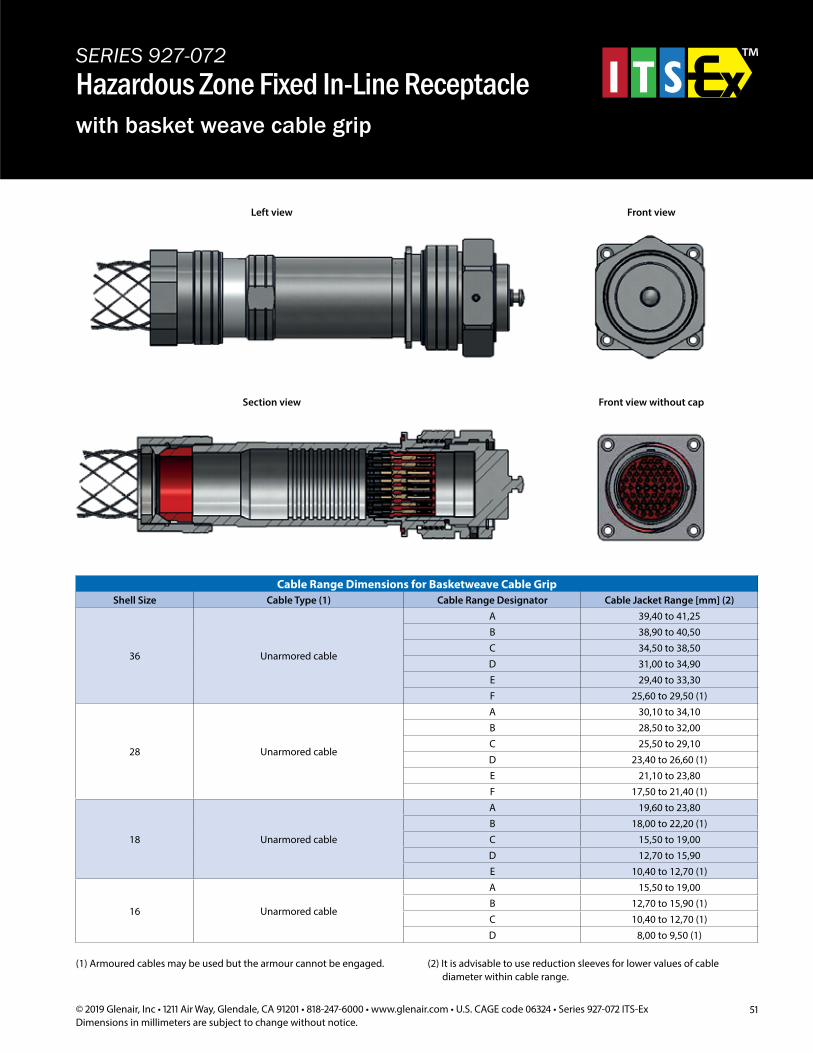
51© 2019 Glenair, Inc • 1211 Air Way, Glendale, CA 91201 • 818-247-6000 • www.glenair.com • U.S. CAGE code 06324 • Series 927-072 ITS-ExDimensions in millimeters are subject to change without notice.
SERIES 927-072Hazardous Zone Fixed In-Line Receptaclewith basket weave cable grip
Left view Front view
Section view Front view without cap
Cable Range Dimensions for Basketweave Cable GripShell Size Cable Type (1) Cable Range Designator Cable Jacket Range [mm] (2)
36 Unarmored cable
A 39,40 to 41,25B 38,90 to 40,50C 34,50 to 38,50D 31,00 to 34,90E 29,40 to 33,30F 25,60 to 29,50 (1)
28 Unarmored cable
A 30,10 to 34,10B 28,50 to 32,00C 25,50 to 29,10D 23,40 to 26,60 (1)E 21,10 to 23,80F 17,50 to 21,40 (1)
18 Unarmored cable
A 19,60 to 23,80B 18,00 to 22,20 (1)C 15,50 to 19,00D 12,70 to 15,90E 10,40 to 12,70 (1)
16 Unarmored cable
A 15,50 to 19,00B 12,70 to 15,90 (1)C 10,40 to 12,70 (1)D 8,00 to 9,50 (1)
(1) Armoured cables may be used but the armour cannot be engaged. (2) It is advisable to use reduction sleeves for lower values of cable diameter within cable range.
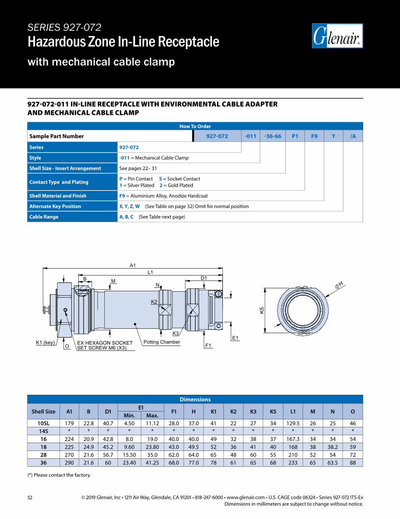
52 © 2019 Glenair, Inc • 1211 Air Way, Glendale, CA 91201 • 818-247-6000 • www.glenair.com • U.S. CAGE code 06324 • Series 927-072 ITS-ExDimensions in millimeters are subject to change without notice.
927-072-011 IN-LINE RECEPTACLE WITH ENVIRONMENTAL CABLE ADAPTER AND MECHANICAL CABLE CLAMP
How To Order
Sample Part Number 927-072 -011 -36-66 P1 F9 Y /A
Series 927-072
Style -011 = Mechanical Cable Clamp
Shell Size - Insert Arrangement See pages 22– 31
Contact Type and PlatingP = Pin Contact S = Socket Contact1 = Silver Plated 2 = Gold Plated
Shell Material and Finish F9 = Aluminium Alloy, Anodize Hardcoat
Alternate Key Position X, Y, Z, W (See Table on page 32) Omit for normal position
Cable Range A, B, C (See Table next page)
M N
L1 A1
K1 (key)
K2
SET SCREW M6 (X3)EX HEXAGON SOCKET
K3
O
D1 B
F1 E1
H
K5
Potting Chamber
Dimensions
Shell Size A1 B D1E1
F1 H K1 K2 K3 K5 L1 M N OMin. Max.
10SL 179 22.8 40.7 4.50 11.12 28.0 37.0 41 22 27 34 129.5 26 25 4614S * * * * * * * * * * * * * * *16 224 20.9 42.8 8.0 19.0 40.0 40.0 49 32 38 37 167.3 34 34 5418 225 24.9 45.2 9.60 23.80 43.0 49.5 52 36 41 40 168 38 38.2 5928 270 21.6 56.7 15.50 35.0 62.0 64.0 65 48 60 55 210 52 54 7236 290 21.6 60 23.40 41.25 68.0 77.0 78 61 65 68 233 65 63.5 88
SERIES 927-072Hazardous Zone In-Line Receptaclewith mechanical cable clamp
(*) Please contact the factory.
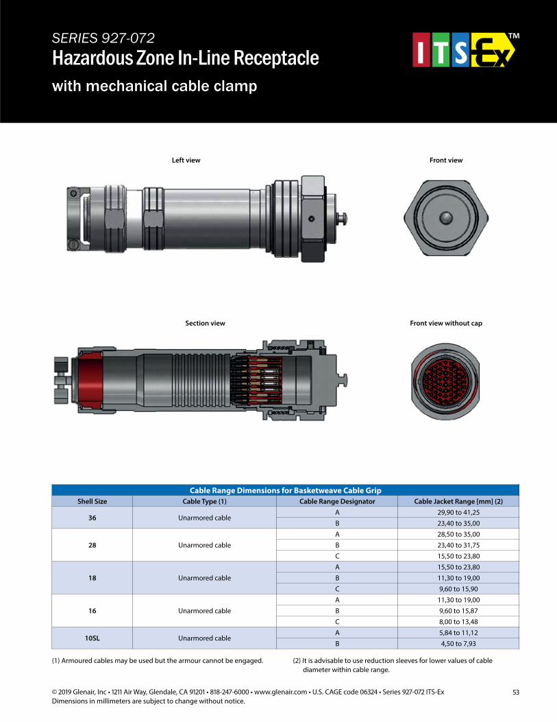
53© 2019 Glenair, Inc • 1211 Air Way, Glendale, CA 91201 • 818-247-6000 • www.glenair.com • U.S. CAGE code 06324 • Series 927-072 ITS-ExDimensions in millimeters are subject to change without notice.
SERIES 927-072Hazardous Zone In-Line Receptaclewith mechanical cable clamp
Left view Front view
Section view Front view without cap
Cable Range Dimensions for Basketweave Cable GripShell Size Cable Type (1) Cable Range Designator Cable Jacket Range [mm] (2)
36 Unarmored cableA 29,90 to 41,25B 23,40 to 35,00
28 Unarmored cableA 28,50 to 35,00B 23,40 to 31,75C 15,50 to 23,80
18 Unarmored cableA 15,50 to 23,80B 11,30 to 19,00C 9,60 to 15,90
16 Unarmored cableA 11,30 to 19,00B 9,60 to 15,87C 8,00 to 13,48
10SL Unarmored cableA 5,84 to 11,12B 4,50 to 7,93
(1) Armoured cables may be used but the armour cannot be engaged. (2) It is advisable to use reduction sleeves for lower values of cable diameter within cable range.
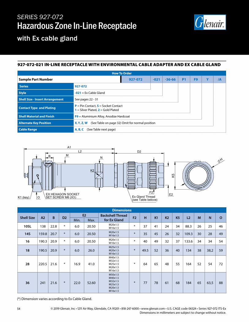
54 © 2019 Glenair, Inc • 1211 Air Way, Glendale, CA 91201 • 818-247-6000 • www.glenair.com • U.S. CAGE code 06324 • Series 927-072 ITS-ExDimensions in millimeters are subject to change without notice.
SERIES 927-072Hazardous Zone In-Line Receptaclewith Ex cable gland
927-072-021 IN-LINE RECEPTACLE WITH ENVIRONMENTAL CABLE ADAPTER AND EX CABLE GLAND
How To Order
Sample Part Number 927-072 -021 -36-66 P1 F9 Y /A
Series 927-072
Style -021 = Ex Cable Gland
Shell Size - Insert Arrangement See pages 22 - 31
Contact Type and PlatingP = Pin Contact, S = Socket Contact1 = Silver Plated, 2 = Gold Plated
Shell Material and Finish F9 = Aluminium Alloy, Anodize Hardcoat
Alternate Key Position X, Y, Z, W (See Table on page 32) Omit for normal position
Cable Range A, B, C (See Table next page)
H
K5
A1
N M
L2
E2 K1 (key) Ex Gland Thread
(see Table belove)SET SCREW M6 (X3)EX HEXAGON SOCKET
K2
F2
D2
O
B
(*) Dimension varies according to Ex Cable Gland.
Dimensions
Shell Size A2 B D2E2 Backshell Thread
for Ex Gland F2 H K1 K2 K5 L2 M N OMin. Max.
10SL 138 22.8 * 6.0 20.50 M20x1.5 M16x1.5 * 37 41 24 34 88.3 26 25 46
14S 159.8 20.7 * 6.0 20.50 M20x1.5 M16x1.5 * 35 45 26 32 109.3 30 28 49
16 190.3 20.9 * 6.0 20.50 M20x1.5 M16x1.5 * 40 49 32 37 133.6 34 34 54
18 190.5 20.9 * 6.0 26.0M25x1.5 M20x1.5 M16x1.5
* 49.5 52 36 40 134 38 38,2 59
28 220.5 21.6 * 16.9 41.0
M40x1.5 M32x1.5 M25x1.5 M20x1.5 M16x1.5
* 64 65 48 55 164 52 54 72
36 241 21.6 * 22.0 52.60
M50x1.5 M40x1.5 M32x1.5 M25x1.5 M20x1.5 M16x1.5
* 77 78 61 68 184 65 63,5 88
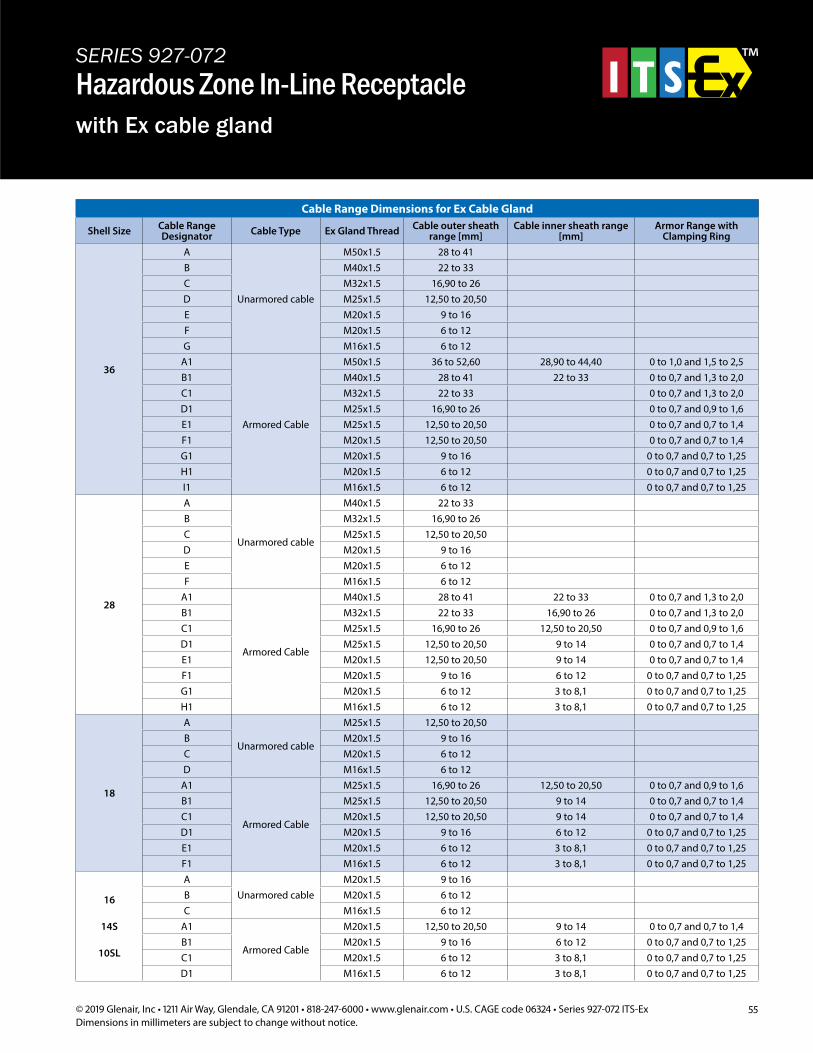
55© 2019 Glenair, Inc • 1211 Air Way, Glendale, CA 91201 • 818-247-6000 • www.glenair.com • U.S. CAGE code 06324 • Series 927-072 ITS-ExDimensions in millimeters are subject to change without notice.
SERIES 927-072Hazardous Zone In-Line Receptaclewith Ex cable gland
Cable Range Dimensions for Ex Cable Gland
Shell Size Cable Range Designator Cable Type Ex Gland Thread Cable outer sheath
range [mm]Cable inner sheath range
[mm]Armor Range with
Clamping Ring
36
A
Unarmored cable
M50x1.5 28 to 41B M40x1.5 22 to 33C M32x1.5 16,90 to 26D M25x1.5 12,50 to 20,50E M20x1.5 9 to 16F M20x1.5 6 to 12G M16x1.5 6 to 12
A1
Armored Cable
M50x1.5 36 to 52,60 28,90 to 44,40 0 to 1,0 and 1,5 to 2,5B1 M40x1.5 28 to 41 22 to 33 0 to 0,7 and 1,3 to 2,0C1 M32x1.5 22 to 33 0 to 0,7 and 1,3 to 2,0D1 M25x1.5 16,90 to 26 0 to 0,7 and 0,9 to 1,6E1 M25x1.5 12,50 to 20,50 0 to 0,7 and 0,7 to 1,4F1 M20x1.5 12,50 to 20,50 0 to 0,7 and 0,7 to 1,4G1 M20x1.5 9 to 16 0 to 0,7 and 0,7 to 1,25H1 M20x1.5 6 to 12 0 to 0,7 and 0,7 to 1,25I1 M16x1.5 6 to 12 0 to 0,7 and 0,7 to 1,25
28
A
Unarmored cable
M40x1.5 22 to 33B M32x1.5 16,90 to 26C M25x1.5 12,50 to 20,50D M20x1.5 9 to 16E M20x1.5 6 to 12F M16x1.5 6 to 12
A1
Armored Cable
M40x1.5 28 to 41 22 to 33 0 to 0,7 and 1,3 to 2,0B1 M32x1.5 22 to 33 16,90 to 26 0 to 0,7 and 1,3 to 2,0C1 M25x1.5 16,90 to 26 12,50 to 20,50 0 to 0,7 and 0,9 to 1,6D1 M25x1.5 12,50 to 20,50 9 to 14 0 to 0,7 and 0,7 to 1,4E1 M20x1.5 12,50 to 20,50 9 to 14 0 to 0,7 and 0,7 to 1,4F1 M20x1.5 9 to 16 6 to 12 0 to 0,7 and 0,7 to 1,25G1 M20x1.5 6 to 12 3 to 8,1 0 to 0,7 and 0,7 to 1,25H1 M16x1.5 6 to 12 3 to 8,1 0 to 0,7 and 0,7 to 1,25
18
A
Unarmored cable
M25x1.5 12,50 to 20,50B M20x1.5 9 to 16C M20x1.5 6 to 12D M16x1.5 6 to 12
A1
Armored Cable
M25x1.5 16,90 to 26 12,50 to 20,50 0 to 0,7 and 0,9 to 1,6B1 M25x1.5 12,50 to 20,50 9 to 14 0 to 0,7 and 0,7 to 1,4C1 M20x1.5 12,50 to 20,50 9 to 14 0 to 0,7 and 0,7 to 1,4D1 M20x1.5 9 to 16 6 to 12 0 to 0,7 and 0,7 to 1,25E1 M20x1.5 6 to 12 3 to 8,1 0 to 0,7 and 0,7 to 1,25F1 M16x1.5 6 to 12 3 to 8,1 0 to 0,7 and 0,7 to 1,25
16
14S
10SL
AUnarmored cable
M20x1.5 9 to 16B M20x1.5 6 to 12C M16x1.5 6 to 12
A1
Armored Cable
M20x1.5 12,50 to 20,50 9 to 14 0 to 0,7 and 0,7 to 1,4B1 M20x1.5 9 to 16 6 to 12 0 to 0,7 and 0,7 to 1,25C1 M20x1.5 6 to 12 3 to 8,1 0 to 0,7 and 0,7 to 1,25D1 M16x1.5 6 to 12 3 to 8,1 0 to 0,7 and 0,7 to 1,25
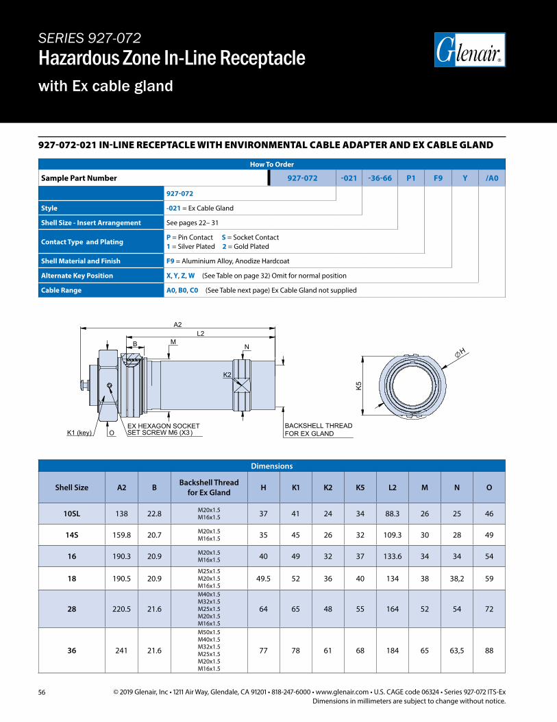
56 © 2019 Glenair, Inc • 1211 Air Way, Glendale, CA 91201 • 818-247-6000 • www.glenair.com • U.S. CAGE code 06324 • Series 927-072 ITS-ExDimensions in millimeters are subject to change without notice.
SERIES 927-072Hazardous Zone In-Line Receptaclewith Ex cable gland
927-072-021 IN-LINE RECEPTACLE WITH ENVIRONMENTAL CABLE ADAPTER AND EX CABLE GLAND
How To Order
Sample Part Number 927-072 -021 -36-66 P1 F9 Y /A0
927-072
Style -021 = Ex Cable Gland
Shell Size - Insert Arrangement See pages 22– 31
Contact Type and PlatingP = Pin Contact S = Socket Contact1 = Silver Plated 2 = Gold Plated
Shell Material and Finish F9 = Aluminium Alloy, Anodize Hardcoat
Alternate Key Position X, Y, Z, W (See Table on page 32) Omit for normal position
Cable Range A0, B0, C0 (See Table next page) Ex Cable Gland not supplied
H K
5
A2
N M
L2
BACKSHELL THREADFOR EX GLANDK1 (key) SET SCREW M6 (X3)
EX HEXAGON SOCKET
K2
O
B
Dimensions
Shell Size A2 B Backshell Thread for Ex Gland H K1 K2 K5 L2 M N O
10SL 138 22.8 M20x1.5M16x1.5 37 41 24 34 88.3 26 25 46
14S 159.8 20.7 M20x1.5 M16x1.5 35 45 26 32 109.3 30 28 49
16 190.3 20.9 M20x1.5 M16x1.5 40 49 32 37 133.6 34 34 54
18 190.5 20.9M25x1.5 M20x1.5 M16x1.5
49.5 52 36 40 134 38 38,2 59
28 220.5 21.6
M40x1.5 M32x1.5 M25x1.5 M20x1.5 M16x1.5
64 65 48 55 164 52 54 72
36 241 21.6
M50x1.5 M40x1.5 M32x1.5 M25x1.5 M20x1.5 M16x1.5
77 78 61 68 184 65 63,5 88
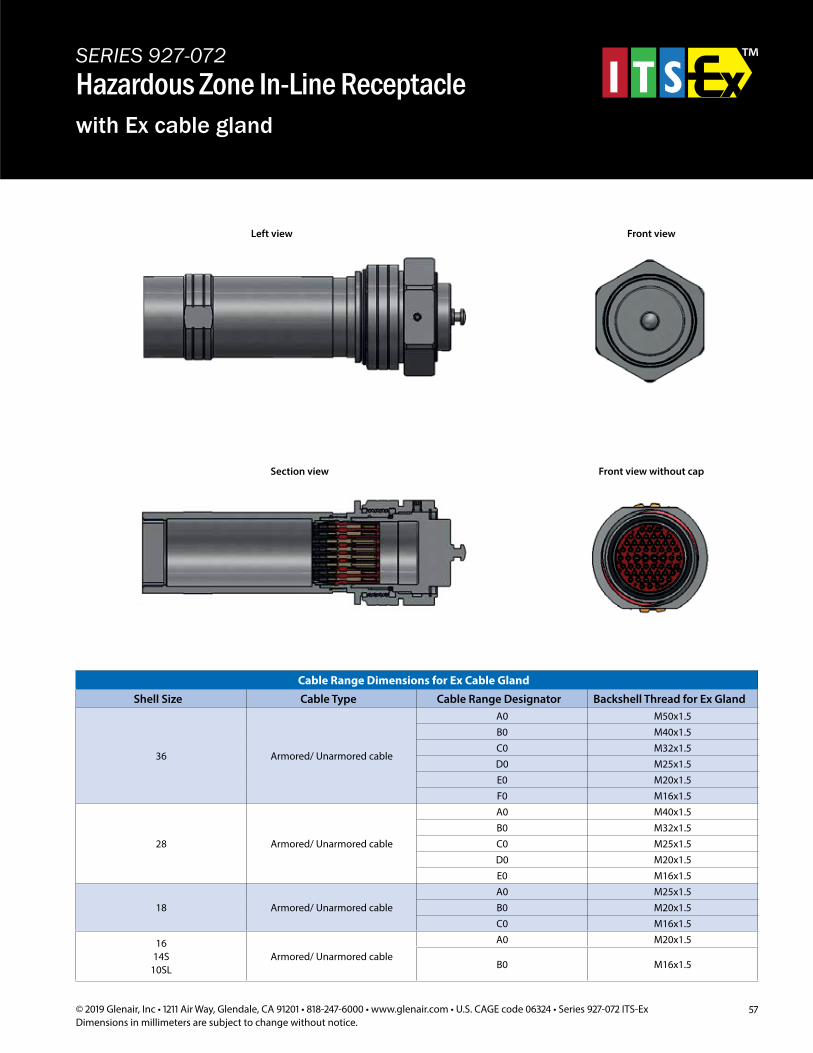
57© 2019 Glenair, Inc • 1211 Air Way, Glendale, CA 91201 • 818-247-6000 • www.glenair.com • U.S. CAGE code 06324 • Series 927-072 ITS-ExDimensions in millimeters are subject to change without notice.
Cable Range Dimensions for Ex Cable Gland
Shell Size Cable Type Cable Range Designator Backshell Thread for Ex Gland
36 Armored/ Unarmored cable
A0 M50x1.5B0 M40x1.5C0 M32x1.5D0 M25x1.5E0 M20x1.5F0 M16x1.5
28 Armored/ Unarmored cable
A0 M40x1.5B0 M32x1.5C0 M25x1.5D0 M20x1.5E0 M16x1.5
18 Armored/ Unarmored cableA0 M25x1.5B0 M20x1.5C0 M16x1.5
1614S
10SLArmored/ Unarmored cable
A0 M20x1.5
B0 M16x1.5
SERIES 927-072Hazardous Zone In-Line Receptaclewith Ex cable gland
Left view Front view
Section view Front view without cap
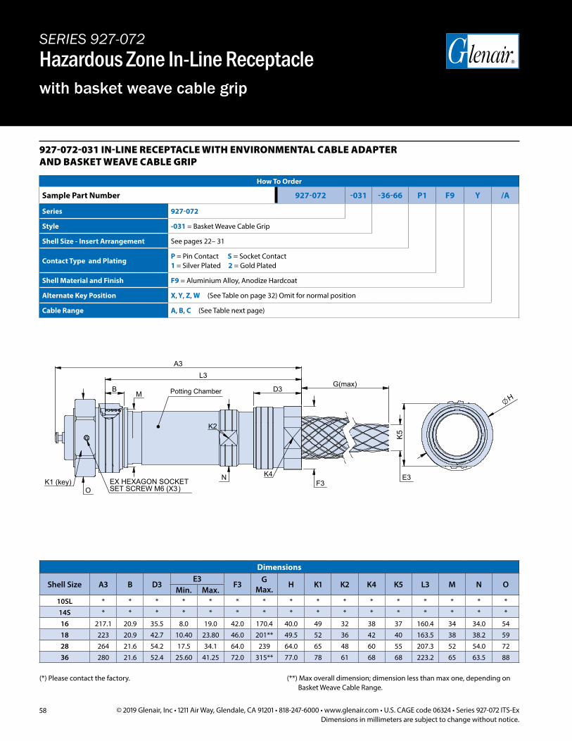
58 © 2019 Glenair, Inc • 1211 Air Way, Glendale, CA 91201 • 818-247-6000 • www.glenair.com • U.S. CAGE code 06324 • Series 927-072 ITS-ExDimensions in millimeters are subject to change without notice.
SERIES 927-072Hazardous Zone In-Line Receptaclewith basket weave cable grip
927-072-031 IN-LINE RECEPTACLE WITH ENVIRONMENTAL CABLE ADAPTER AND BASKET WEAVE CABLE GRIP
How To Order
Sample Part Number 927-072 -031 -36-66 P1 F9 Y /A
Series 927-072
Style -031 = Basket Weave Cable Grip
Shell Size - Insert Arrangement See pages 22– 31
Contact Type and PlatingP = Pin Contact S = Socket Contact1 = Silver Plated 2 = Gold Plated
Shell Material and Finish F9 = Aluminium Alloy, Anodize Hardcoat
Alternate Key Position X, Y, Z, W (See Table on page 32) Omit for normal position
Cable Range A, B, C (See Table next page)
H K
5
K1 (key)
K2
SET SCREW M6 (X3)EX HEXAGON SOCKET
K4
O
M
N
L3
D3
F3
B
E3
A3
G(max) Potting Chamber
Dimensions
Shell Size A3 B D3E3
F3 G Max. H K1 K2 K4 K5 L3 M N O
Min. Max.10SL * * * * * * * * * * * * * * * *14S * * * * * * * * * * * * * * * *16 217.1 20.9 35.5 8.0 19.0 42.0 170.4 40.0 49 32 38 37 160.4 34 34.0 5418 223 20.9 42.7 10.40 23.80 46.0 201** 49.5 52 36 42 40 163.5 38 38.2 5928 264 21.6 54.2 17.5 34.1 64.0 239 64.0 65 48 60 55 207.3 52 54.0 7236 280 21.6 52.4 25.60 41.25 72.0 315** 77.0 78 61 68 68 223.2 65 63.5 88
(*) Please contact the factory. (**) Max overall dimension; dimension less than max one, depending on Basket Weave Cable Range.
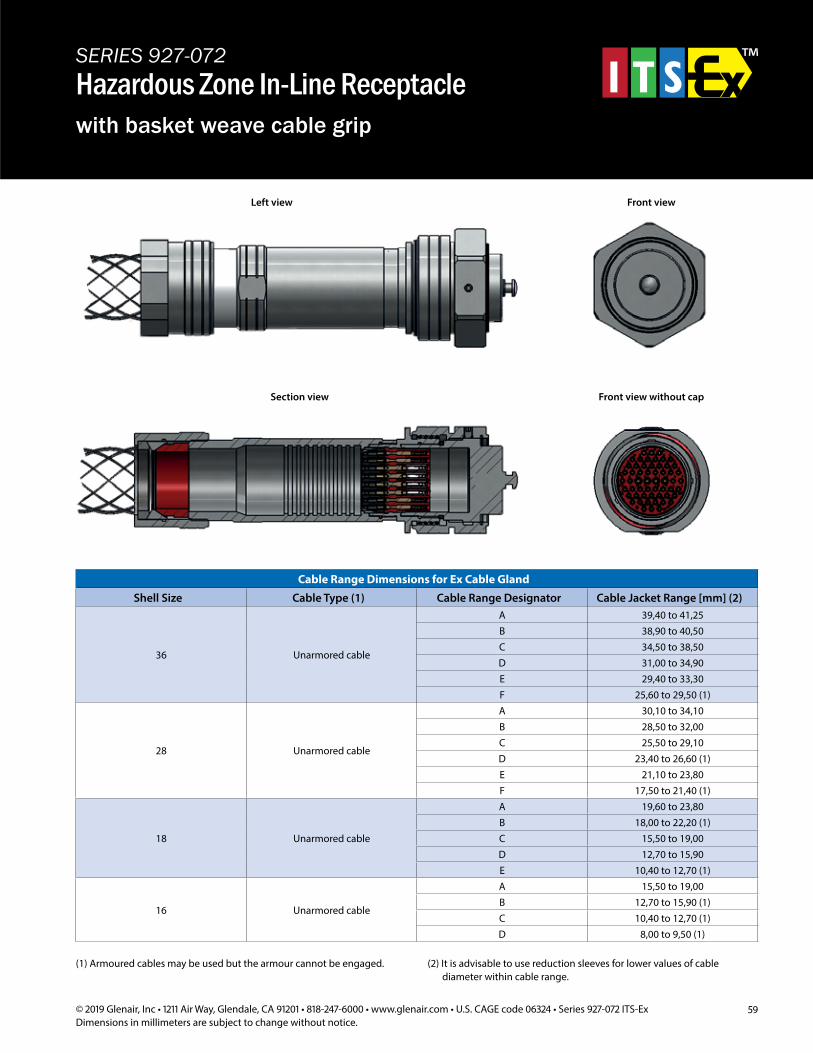
59© 2019 Glenair, Inc • 1211 Air Way, Glendale, CA 91201 • 818-247-6000 • www.glenair.com • U.S. CAGE code 06324 • Series 927-072 ITS-ExDimensions in millimeters are subject to change without notice.
SERIES 927-072Hazardous Zone In-Line Receptaclewith basket weave cable grip
Left view Front view
Section view Front view without cap
Cable Range Dimensions for Ex Cable Gland
Shell Size Cable Type (1) Cable Range Designator Cable Jacket Range [mm] (2)
36 Unarmored cable
A 39,40 to 41,25B 38,90 to 40,50C 34,50 to 38,50D 31,00 to 34,90E 29,40 to 33,30F 25,60 to 29,50 (1)
28 Unarmored cable
A 30,10 to 34,10B 28,50 to 32,00C 25,50 to 29,10D 23,40 to 26,60 (1)E 21,10 to 23,80F 17,50 to 21,40 (1)
18 Unarmored cable
A 19,60 to 23,80B 18,00 to 22,20 (1)C 15,50 to 19,00D 12,70 to 15,90E 10,40 to 12,70 (1)
16 Unarmored cable
A 15,50 to 19,00B 12,70 to 15,90 (1)C 10,40 to 12,70 (1)D 8,00 to 9,50 (1)
(1) Armoured cables may be used but the armour cannot be engaged. (2) It is advisable to use reduction sleeves for lower values of cable diameter within cable range.
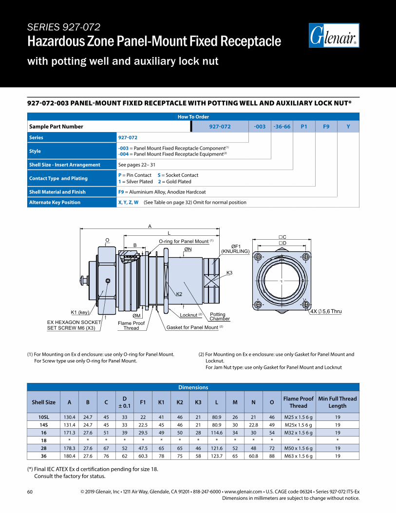
60 © 2019 Glenair, Inc • 1211 Air Way, Glendale, CA 91201 • 818-247-6000 • www.glenair.com • U.S. CAGE code 06324 • Series 927-072 ITS-ExDimensions in millimeters are subject to change without notice.
SERIES 927-072Hazardous Zone Panel-Mount Fixed Receptaclewith potting well and auxiliary lock nut
927-072-003 PANEL-MOUNT FIXED RECEPTACLE WITH POTTING WELL AND AUXILIARY LOCK NUT*
How To Order
Sample Part Number 927-072 -003 -36-66 P1 F9 Y
Series 927-072
Style -003 = Panel Mount Fixed Receptacle Component(1) -004 = Panel Mount Fixed Receptacle Equipment(2)
Shell Size - Insert Arrangement See pages 22– 31
Contact Type and PlatingP = Pin Contact S = Socket Contact1 = Silver Plated 2 = Gold Plated
Shell Material and Finish F9 = Aluminium Alloy, Anodize Hardcoat
Alternate Key Position X, Y, Z, W (See Table on page 32) Omit for normal position
Dimensions
Shell Size A B C D ± 0.1 F1 K1 K2 K3 L M N O Flame Proof
ThreadMin Full Thread
Length
10SL 130.4 24.7 45 33 22 41 46 21 80.9 26 21 46 M25 x 1.5 6 g 1914S 131.4 24.7 45 33 22.5 45 46 21 80.9 30 22.8 49 M25x 1.5 6 g 1916 171.3 27.6 51 39 29.5 49 50 28 114.6 34 30 54 M32 x 1.5 6 g 1918 * * * * * * * * * * * * * *28 178.3 27.6 67 52 47.5 65 65 46 121.6 52 48 72 M50 x 1.5 6 g 1936 180.4 27.6 76 62 60.3 78 75 58 123.7 65 60.8 88 M63 x 1.5 6 g 19
(1) For Mounting on Ex d enclosure: use only O-ring for Panel Mount. For Screw type use only O-ring for Panel Mount.
(2) For Mounting on Ex e enclosure: use only Gasket for Panel Mount and Locknut. For Jam Nut type: use only Gasket for Panel Mount and Locknut
(*) Final IEC ATEX Ex d certification pending for size 18. Consult the factory for status.
SET SCREW M6 (X3)EX HEXAGON SOCKET
K1 (key) ØM
Flame ProofThread Gasket for Panel Mount (2)
Locknut (2) PottingChamber
O-ring for Panel Mount (1)
ØN ØF1(KNURLING)
K3
K2
L
B
A
O CD
5,64X Thru
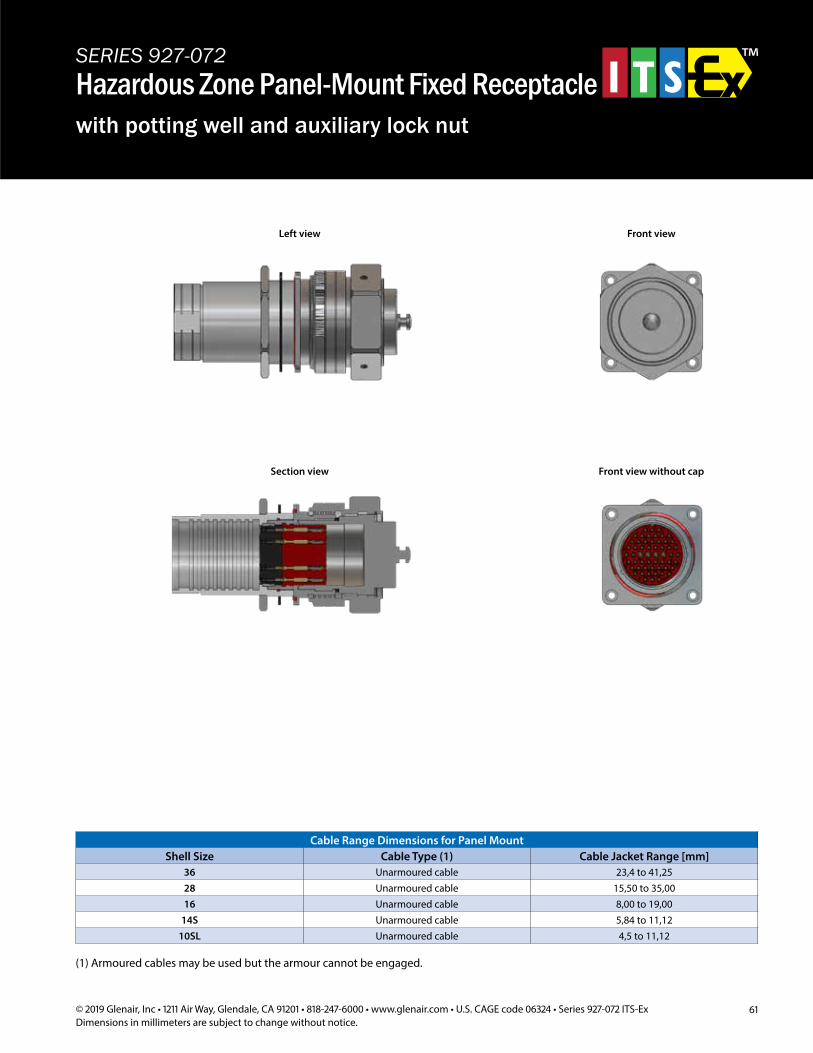
61© 2019 Glenair, Inc • 1211 Air Way, Glendale, CA 91201 • 818-247-6000 • www.glenair.com • U.S. CAGE code 06324 • Series 927-072 ITS-ExDimensions in millimeters are subject to change without notice.
SERIES 927-072Hazardous Zone Panel-Mount Fixed Receptaclewith potting well and auxiliary lock nut
(1) Armoured cables may be used but the armour cannot be engaged.
Cable Range Dimensions for Panel MountShell Size Cable Type (1) Cable Jacket Range [mm]
36 Unarmoured cable 23,4 to 41,2528 Unarmoured cable 15,50 to 35,0016 Unarmoured cable 8,00 to 19,00
14S Unarmoured cable 5,84 to 11,1210SL Unarmoured cable 4,5 to 11,12
Left view Front view
Section view Front view without cap
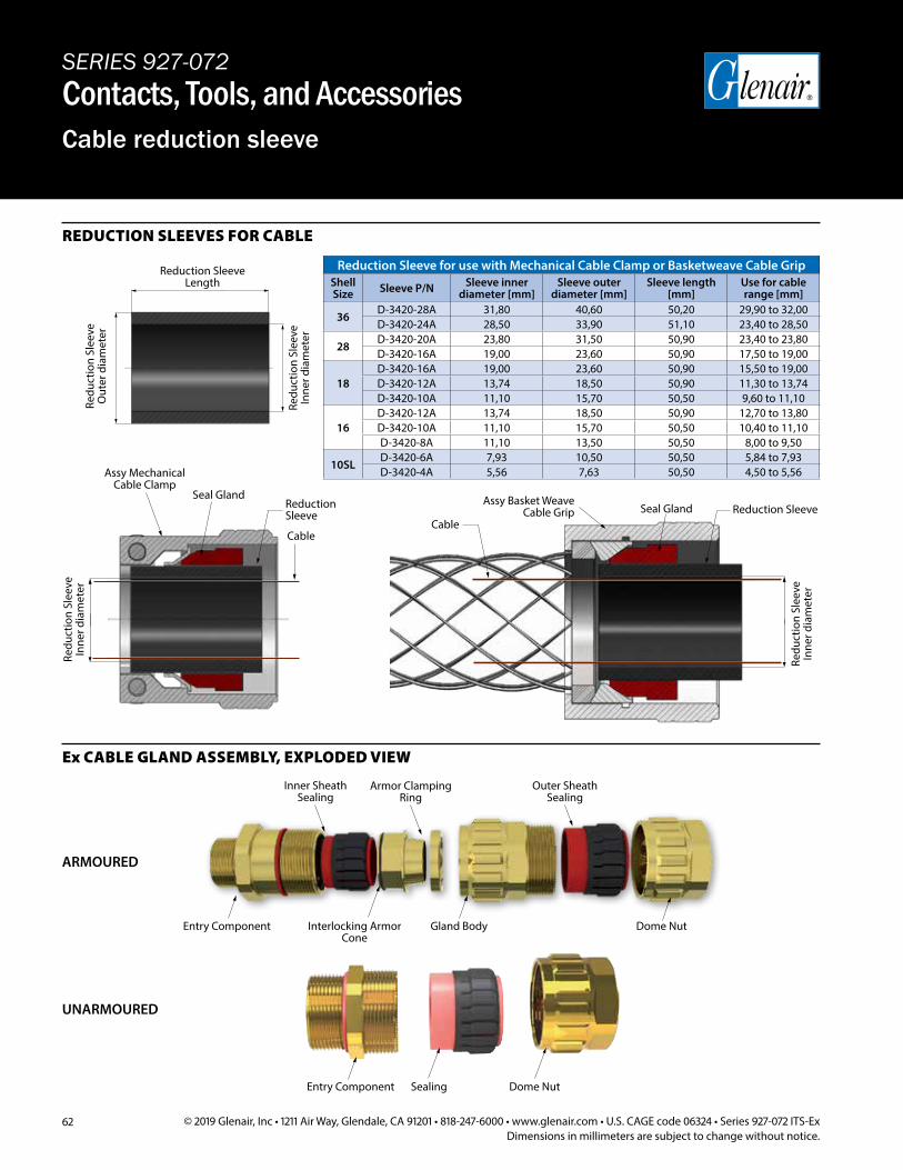
62 © 2019 Glenair, Inc • 1211 Air Way, Glendale, CA 91201 • 818-247-6000 • www.glenair.com • U.S. CAGE code 06324 • Series 927-072 ITS-ExDimensions in millimeters are subject to change without notice.
REDUCTION SLEEVES FOR CABLE
Ex CABLE GLAND ASSEMBLY, EXPLODED VIEW
Reduction Sleeve for use with Mechanical Cable Clamp or Basketweave Cable GripShell Size Sleeve P/N Sleeve inner
diameter [mm]Sleeve outer
diameter [mm]Sleeve length
[mm]Use for cable range [mm]
36D-3420-28A 31,80 40,60 50,20 29,90 to 32,00D-3420-24A 28,50 33,90 51,10 23,40 to 28,50
28D-3420-20A 23,80 31,50 50,90 23,40 to 23,80D-3420-16A 19,00 23,60 50,90 17,50 to 19,00
18D-3420-16A 19,00 23,60 50,90 15,50 to 19,00D-3420-12A 13,74 18,50 50,90 11,30 to 13,74D-3420-10A 11,10 15,70 50,50 9,60 to 11,10
16D-3420-12A 13,74 18,50 50,90 12,70 to 13,80D-3420-10A 11,10 15,70 50,50 10,40 to 11,10D-3420-8A 11,10 13,50 50,50 8,00 to 9,50
10SLD-3420-6A 7,93 10,50 50,50 5,84 to 7,93D-3420-4A 5,56 7,63 50,50 4,50 to 5,56
Reduction Sleeve Length
Redu
ctio
n Sl
eeve
In
ner d
iam
eter
Redu
ctio
n Sl
eeve
O
uter
dia
met
er
Redu
ctio
n Sl
eeve
In
ner d
iam
eter
Assy Mechanical Cable Clamp
Reduction Sleeve
Seal Gland
Cable
Assy Basket WeaveCable Grip Reduction SleeveSeal Gland
Cable
Redu
ctio
n Sl
eeve
In
ner d
iam
eter
SERIES 927-072Contacts, Tools, and AccessoriesCable reduction sleeve
ARMOURED
UNARMOURED
Entry Component Dome NutSealing
Inner Sheath Sealing
Entry Component Interlocking Armor Cone
Armor Clamping Ring
Gland Body
Outer Sheath Sealing
Dome Nut
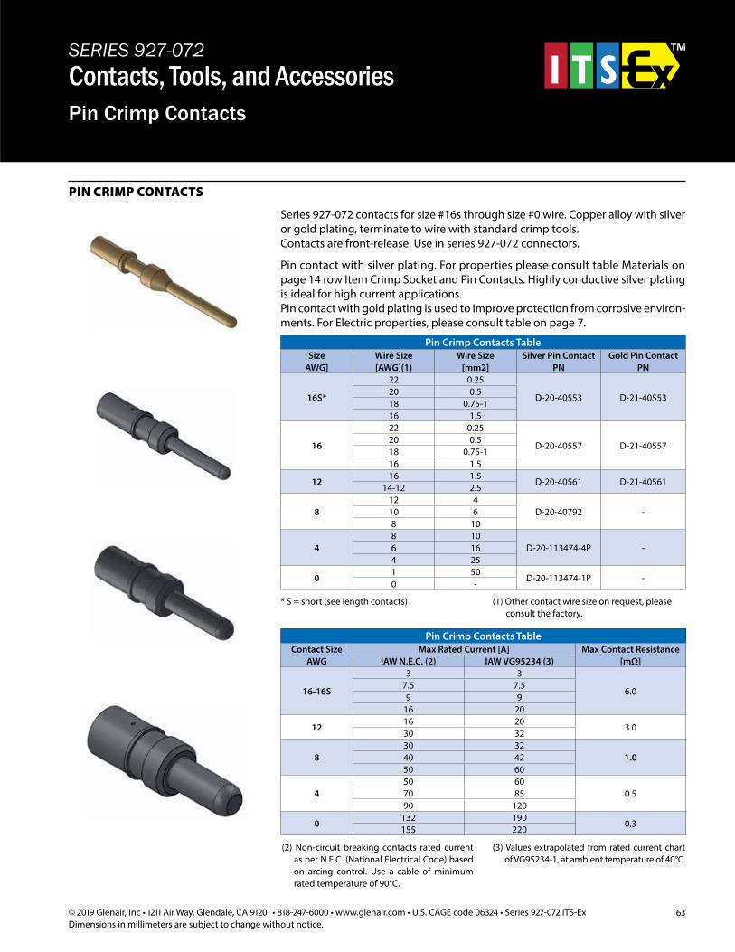
63© 2019 Glenair, Inc • 1211 Air Way, Glendale, CA 91201 • 818-247-6000 • www.glenair.com • U.S. CAGE code 06324 • Series 927-072 ITS-ExDimensions in millimeters are subject to change without notice.
PIN CRIMP CONTACTS
Pin Crimp Contacts TableSize
AWG]Wire Size [AWG](1)
Wire Size [mm2]
Silver Pin Contact PN
Gold Pin Contact PN
16S*
22 0.25
D-20-40553 D-21-4055320 0.518 0.75-116 1.5
16
22 0.25
D-20-40557 D-21-4055720 0.518 0.75-116 1.5
1216 1.5
D-20-40561 D-21-4056114-12 2.5
812 4
D-20-40792 -10 68 10
48 10
D-20-113474-4P -6 164 25
01 50
D-20-113474-1P -0 -
Pin Crimp Contacts TableContact Size
AWGMax Rated Current [A] Max Contact Resistance
[mΩ]IAW N.E.C. (2) IAW VG95234 (3)
16-16S
3 3
6.07.5 7.59 9
16 20
1216 20
3.030 32
830 32
1.040 4250 60
450 60
0.570 8590 120
0132 190
0.3155 220
* S = short (see length contacts) (1) Other contact wire size on request, please consult the factory.
(2) Non-circuit breaking contacts rated current as per N.E.C. (National Electrical Code) based on arcing control. Use a cable of minimum rated temperature of 90°C.
(3) Values extrapolated from rated current chart of VG95234-1, at ambient temperature of 40°C.
SERIES 927-072Contacts, Tools, and AccessoriesPin Crimp Contacts
Series 927-072 contacts for size #16s through size #0 wire. Copper alloy with silver or gold plating, terminate to wire with standard crimp tools.Contacts are front-release. Use in series 927-072 connectors.
Pin contact with silver plating. For properties please consult table Materials on page 14 row Item Crimp Socket and Pin Contacts. Highly conductive silver plating is ideal for high current applications.Pin contact with gold plating is used to improve protection from corrosive environ-ments. For Electric properties, please consult table on page 7.
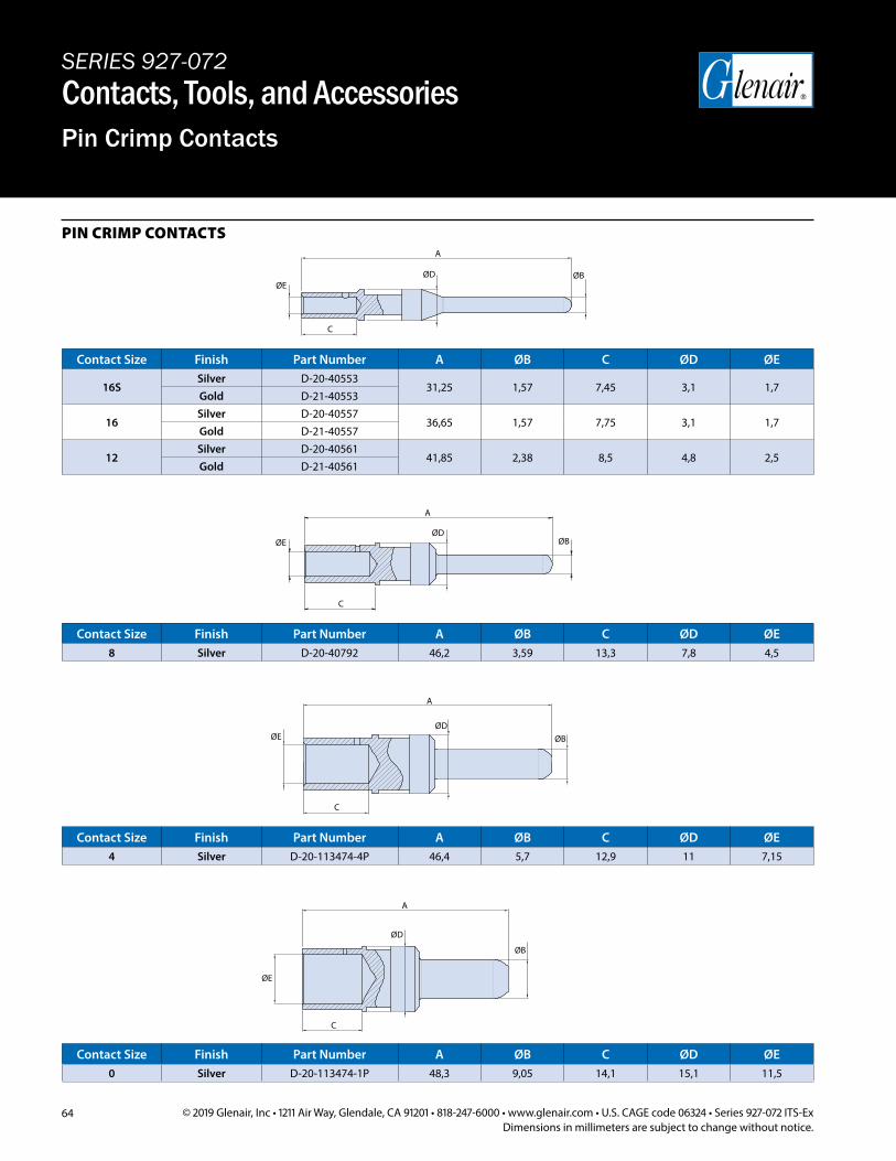
64 © 2019 Glenair, Inc • 1211 Air Way, Glendale, CA 91201 • 818-247-6000 • www.glenair.com • U.S. CAGE code 06324 • Series 927-072 ITS-ExDimensions in millimeters are subject to change without notice.
Contact Size Finish Part Number A ØB C ØD ØE
16SSilver D-20-40553
31,25 1,57 7,45 3,1 1,7Gold D-21-40553
16Silver D-20-40557
36,65 1,57 7,75 3,1 1,7Gold D-21-40557
12Silver D-20-40561
41,85 2,38 8,5 4,8 2,5Gold D-21-40561
Contact Size Finish Part Number A ØB C ØD ØE8 Silver D-20-40792 46,2 3,59 13,3 7,8 4,5
Contact Size Finish Part Number A ØB C ØD ØE4 Silver D-20-113474-4P 46,4 5,7 12,9 11 7,15
Contact Size Finish Part Number A ØB C ØD ØE0 Silver D-20-113474-1P 48,3 9,05 14,1 15,1 11,5
PIN CRIMP CONTACTS A
ØB
C
ØDØE
A
ØB
C
ØDØE
A
ØB
C
ØDØE
A
ØB
C
ØD
ØE
SERIES 927-072Contacts, Tools, and AccessoriesPin Crimp Contacts
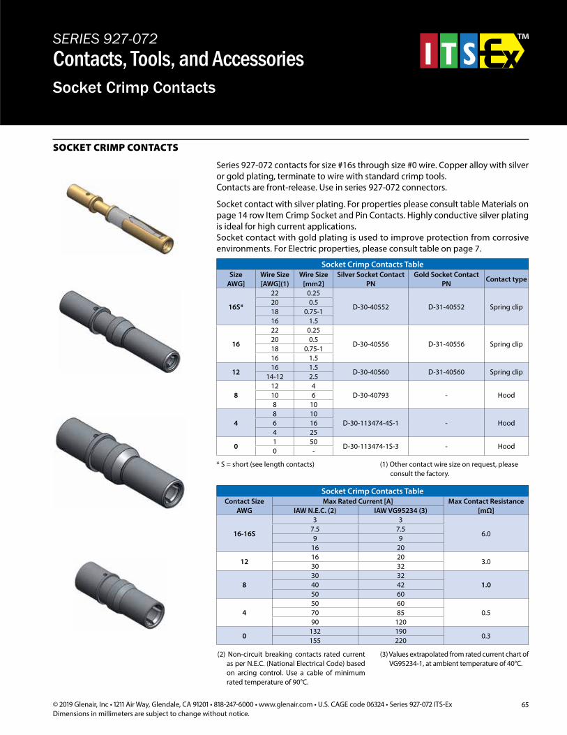
65© 2019 Glenair, Inc • 1211 Air Way, Glendale, CA 91201 • 818-247-6000 • www.glenair.com • U.S. CAGE code 06324 • Series 927-072 ITS-ExDimensions in millimeters are subject to change without notice.
SOCKET CRIMP CONTACTS
SERIES 927-072Contacts, Tools, and AccessoriesSocket Crimp Contacts
Series 927-072 contacts for size #16s through size #0 wire. Copper alloy with silver or gold plating, terminate to wire with standard crimp tools.Contacts are front-release. Use in series 927-072 connectors.
Socket contact with silver plating. For properties please consult table Materials on page 14 row Item Crimp Socket and Pin Contacts. Highly conductive silver plating is ideal for high current applications.Socket contact with gold plating is used to improve protection from corrosive environments. For Electric properties, please consult table on page 7.
Socket Crimp Contacts TableSize
AWG]Wire Size [AWG](1)
Wire Size [mm2]
Silver Socket Contact PN
Gold Socket Contact PN
Contact type
16S*
22 0.25
D-30-40552 D-31-40552 Spring clip20 0.518 0.75-116 1.5
16
22 0.25
D-30-40556 D-31-40556 Spring clip20 0.518 0.75-116 1.5
1216 1.5
D-30-40560 D-31-40560 Spring clip14-12 2.5
812 4
D-30-40793 - Hood10 68 10
48 10
D-30-113474-4S-1 - Hood6 164 25
01 50
D-30-113474-1S-3 - Hood0 -
* S = short (see length contacts) (1) Other contact wire size on request, please consult the factory.
Socket Crimp Contacts TableContact Size
AWGMax Rated Current [A] Max Contact Resistance
[mΩ]IAW N.E.C. (2) IAW VG95234 (3)
16-16S
3 3
6.07.5 7.59 9
16 20
1216 20
3.030 32
830 32
1.040 4250 60
450 60
0.570 8590 120
0132 190
0.3155 220
(2) Non-circuit breaking contacts rated current as per N.E.C. (National Electrical Code) based on arcing control. Use a cable of minimum rated temperature of 90°C.
(3) Values extrapolated from rated current chart of VG95234-1, at ambient temperature of 40°C.
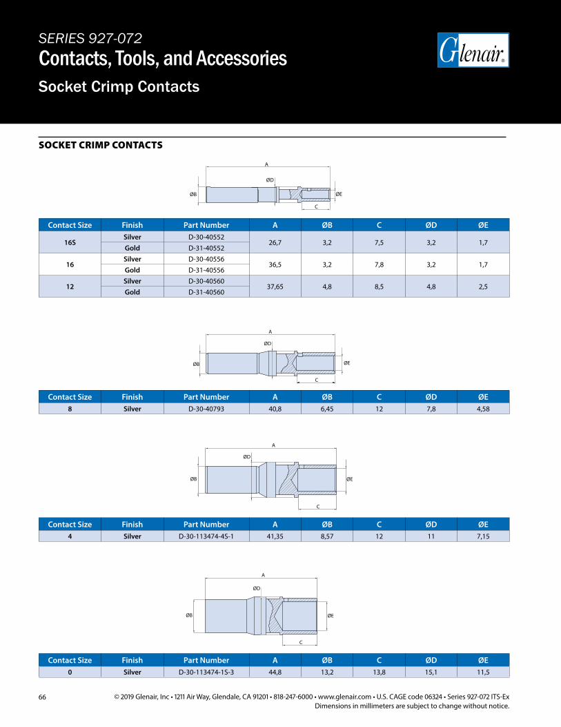
66 © 2019 Glenair, Inc • 1211 Air Way, Glendale, CA 91201 • 818-247-6000 • www.glenair.com • U.S. CAGE code 06324 • Series 927-072 ITS-ExDimensions in millimeters are subject to change without notice.
SOCKET CRIMP CONTACTS
A
ØB
C
ØD
ØE
A
ØB
ØD
ØE
C
A
ØB
ØD
ØE
C
A
ØB
ØD
ØE
C
SERIES 927-072Contacts, Tools, and AccessoriesSocket Crimp Contacts
Contact Size Finish Part Number A ØB C ØD ØE
16SSilver D-30-40552
26,7 3,2 7,5 3,2 1,7Gold D-31-40552
16Silver D-30-40556
36,5 3,2 7,8 3,2 1,7Gold D-31-40556
12Silver D-30-40560
37,65 4,8 8,5 4,8 2,5Gold D-31-40560
Contact Size Finish Part Number A ØB C ØD ØE8 Silver D-30-40793 40,8 6,45 12 7,8 4,58
Contact Size Finish Part Number A ØB C ØD ØE4 Silver D-30-113474-4S-1 41,35 8,57 12 11 7,15
Contact Size Finish Part Number A ØB C ØD ØE0 Silver D-30-113474-1S-3 44,8 13,2 13,8 15,1 11,5
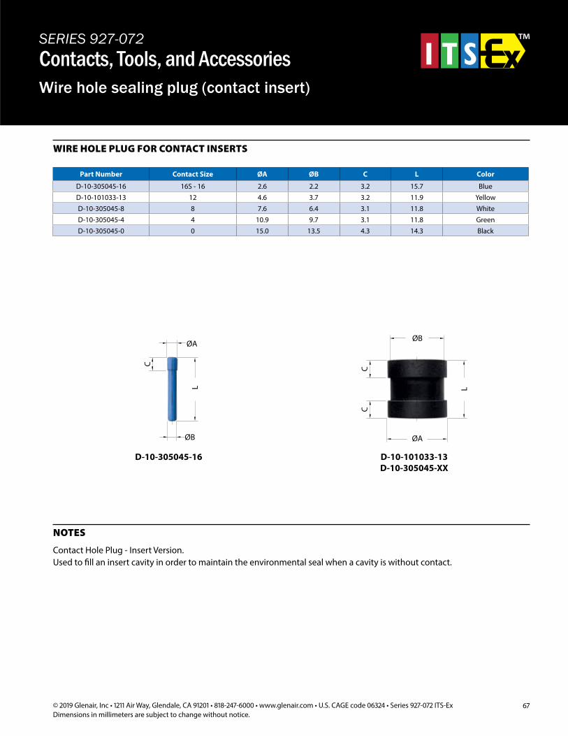
67© 2019 Glenair, Inc • 1211 Air Way, Glendale, CA 91201 • 818-247-6000 • www.glenair.com • U.S. CAGE code 06324 • Series 927-072 ITS-ExDimensions in millimeters are subject to change without notice.
D-10-305045-16 D-10-101033-13 D-10-305045-XX
Part Number Contact Size ØA ØB C L Color
D-10-305045-16 16S - 16 2.6 2.2 3.2 15.7 BlueD-10-101033-13 12 4.6 3.7 3.2 11.9 YellowD-10-305045-8 8 7.6 6.4 3.1 11.8 WhiteD-10-305045-4 4 10.9 9.7 3.1 11.8 GreenD-10-305045-0 0 15.0 13.5 4.3 14.3 Black
NOTES
Contact Hole Plug - Insert Version.Used to fill an insert cavity in order to maintain the environmental seal when a cavity is without contact.
WIRE HOLE PLUG FOR CONTACT INSERTS
SERIES 927-072Contacts, Tools, and AccessoriesWire hole sealing plug (contact insert)
D-10-101033-13D-10-305045-XX
L
ØB
ØA
CC
D-10-305045-16
ØA
L
C
ØB
D-10-101033-13D-10-305045-XX
L
ØB
ØA
CC
D-10-305045-16
ØA
L
C
ØB
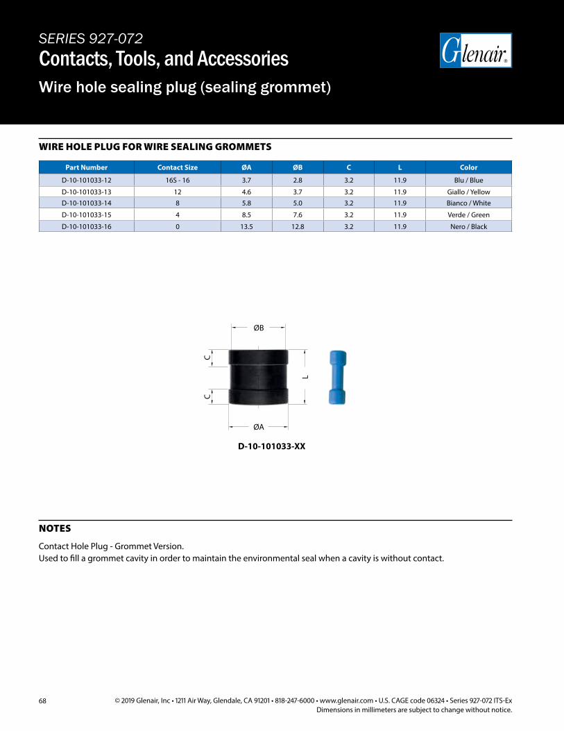
68 © 2019 Glenair, Inc • 1211 Air Way, Glendale, CA 91201 • 818-247-6000 • www.glenair.com • U.S. CAGE code 06324 • Series 927-072 ITS-ExDimensions in millimeters are subject to change without notice.
D-10-101033-XX
Part Number Contact Size ØA ØB C L Color
D-10-101033-12 16S - 16 3.7 2.8 3.2 11.9 Blu / Blue
D-10-101033-13 12 4.6 3.7 3.2 11.9 Giallo / YellowD-10-101033-14 8 5.8 5.0 3.2 11.9 Bianco / White
D-10-101033-15 4 8.5 7.6 3.2 11.9 Verde / Green
D-10-101033-16 0 13.5 12.8 3.2 11.9 Nero / Black
NOTES
Contact Hole Plug - Grommet Version.Used to fill a grommet cavity in order to maintain the environmental seal when a cavity is without contact.
WIRE HOLE PLUG FOR WIRE SEALING GROMMETS
SERIES 927-072Contacts, Tools, and AccessoriesWire hole sealing plug (sealing grommet)
L
ØB
ØA
CC
D-10-101033-XX
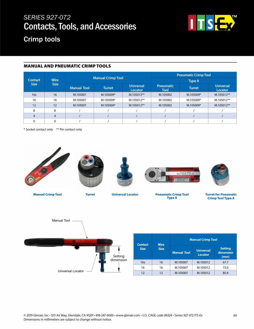
69© 2019 Glenair, Inc • 1211 Air Way, Glendale, CA 91201 • 818-247-6000 • www.glenair.com • U.S. CAGE code 06324 • Series 927-072 ITS-ExDimensions in millimeters are subject to change without notice.
* Socket contact only ** Pin contact only
Universal LocatorTurretManual Crimp Tool
MANUAL AND PNEUMATIC CRIMP TOOLS
Pneumatic Crimp Tool Type A
Turret for Pneumatic Crimp Tool Type A
Contact Size
Wire Size
Manual Crimp ToolPneumatic Crimp Tool
Type A
Manual Tool Turret Universal Locator
Pneumatic Tool Turret Universal
Locator16s 16 M.105007 M.105009* M.105012** M.105002 M.105009* M.105012**
16 16 M.105007 M.105009* M.105012** M.105002 M.105009* M.105012**
12 12 M.105007 M.105009* M.105012** M.105002 M.105009* M.105012**
8 8 / / / / / /
4 4 / / / / / /
0 0 / / / / / /
SERIES 927-072Contacts, Tools, and AccessoriesCrimp tools
Manual Tool
Contact Size
Wire Size
Manual Crimp Tool
Manual ToolUniversal
Locator
Setting dimension
[mm]
16s 16 M.105007 M.105012 67.7
16 16 M.105007 M.105012 73.0
12 12 M.105007 M.105012 85.4Universal Locator
Settingdimension
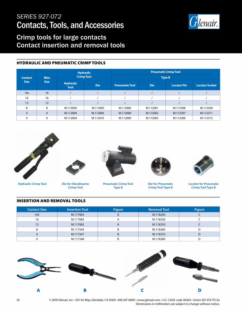
70 © 2019 Glenair, Inc • 1211 Air Way, Glendale, CA 91201 • 818-247-6000 • www.glenair.com • U.S. CAGE code 06324 • Series 927-072 ITS-ExDimensions in millimeters are subject to change without notice.
Pneumatic Crimp Tool Type B
Contact Size
Wire Size
HydraulicCrimp Tool
Pneumatic Crimp Tool
Type B
Hydraulic Tool
Die Pneumatic Tool Die Locator Pin Locator Socket
16s 16 / / / / / /
16 16 / / / / / /
12 12 / / / / / /
8 8 M.112004 M.112005 M.112000 M.112001 M.112308 M.112309
4 4 M.112004 M.112006 M.112000 M.112002 M.112307 M.112311
0 0 M.112004 M.112010 M.112000 M.112003 M.112306 M.112313
Contact Size Insertion Tool Figure Removal Tool Figure16S M.117083 A M.118250 C16 M.117083 A M.118250 C
12 M.117082 A M.118250 C
8 M.117344 B M.118260 D4 M.117347 B M.118270 D0 M.117348 B M.118280 D
INSERTION AND REMOVAL TOOLS
HYDRAULIC AND PNEUMATIC CRIMP TOOLS
A B C D
Die For PneumaticCrimp Tool Type B
Locator for Pneumatic Crimp Tool Type B
Die for OleodinamicCrimp Tool
SERIES 927-072Contacts, Tools, and AccessoriesCrimp tools for large contacts Contact insertion and removal tools
Hydraulic Crimp Tool
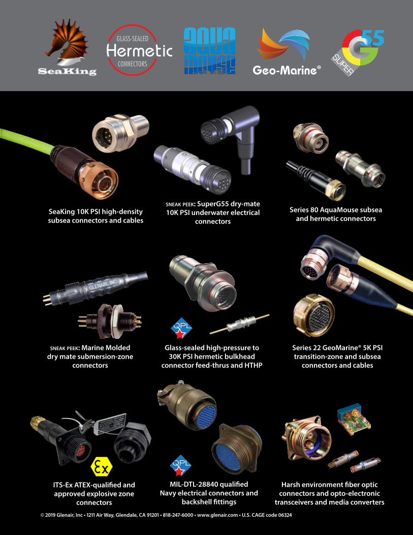
sneak peek: Marine Molded dry mate submersion-zone
connectors
Series 22 GeoMarine® 5K PSI transition-zone and subsea
connectors and cables
Glass-sealed high-pressure to 30K PSI hermetic bulkhead
connector feed-thrus and HTHP
Series 80 AquaMouse subsea and hermetic connectors
MIL-DTL-28840 qualified Navy electrical connectors and
backshell fittings
ITS-Ex ATEX-qualified and approved explosive zone
connectors
Harsh environment fiber optic connectors and opto-electronic
transceivers and media converters
SeaKing 10K PSI high-density subsea connectors and cables
Geo-Marine®
sneak peek: SuperG55 dry-mate 10K PSI underwater electrical
connectors
© 2019 Glenair, Inc • 1211 Air Way, Glendale, CA 91201 • 818-247-6000 • www.glenair.com • U.S. CAGE code 06324
Glenair, Inc.1211 Air Way • Glendale, California • 91201-2497
Telephone: 818-247-6000 • Fax: 818-500-9912 • [email protected]
Telephone:+44-1623-638100
Facsimile:+44-1623-638111
Glenair UK Ltd40 Lower Oakham WayOakham Business ParkMansfield, Notts NG18 5BY England
Telephone:06172 / 68 16 0
Facsimile:06172 / 68 16 [email protected]
Glenair GmbHSchaberweg 2861348 Bad HomburgGermany
Telephone:+33-5-34-40-97-40
Facsimile:+33-5-61-47-86-10
Glenair France SARL7, Avenue ParmentierImmeuble Central Parc #231200 ToulouseFrance
Telephone:847-679-8833
Facsimile:847-679-8849
Glenair Microway Systems7000 North Lawndale AvenueLincolnwood, IL60712
Telephone:[email protected]
Glenair Nordic ABGustav III : S Boulevard 42SE-169 27 SolnaSweden
Telephone:+34-925-89-29-88
Facsimile:+34-925-89-29-87
Glenair IbericaC/ La Vega, 1645612 VeladaSpain
Telephone:203-741-1115
Facsimile:203-741-0053
Glenair Power Products Group20 Sterling DriveWallingford, CT 06492
Telephone: +39-051-782811
Facsimile:+39-051-782259
Telephone: +82-31-8068-1090
Facsimile:+82-31-8068-1092
Glenair Italia S.p.A.Via Del Lavoro, 7 40057 Quarto Inferiore – Granarolo dell’EmiliaBologna, Italy
Glenair Korea B-1304 Gunpo IT Valley 148 Gosan-Ro, Gunpo-Si Kyunggi-Do, Korea435-733
INTERCONNECT SOLUTIONS
MISSION-CRITICAL
© 2019 Glenair, Inc. Printed in Italy
CAT-151