Embed Size (px)
Citation preview

ITA
LIA
NO
EN
GLI
SH
FRA
NC
AIS
DE
UT
SC
HRCA/15950/000 RCA/15951/000
RCA/15948/000 RCA/15949/000
Kits distribuzione ad aria - Air distribution kits
Boîte de distribution air - Lutfversorgungskit
Professional LineIstruzioni per l’installazione - Installation instructions
Montage - Einbaueinleitung
ITA
LIA
NO
AVVERTENZE E PRECAUZIONI
Questi carrelli devono essere utilizzati da persone esperte nel settore del modellismo aereo.E’ sconsigliato l’utilizzo ai minori di anni 12 se non seguiti da un adulto.L’impianto di questi carrelli una volta caricato contiene olio od aria compressa ad alta pressione, evitate di staccare la tu-bazione quando l’impianto è in pressione.Questi carrelli devono essere utilizzati esclusivamente per aeromodelli.Allontanate qualsiasi parte del corpo e non trattenete le gambe dei carrelli durante il funzionamento.Non caricate i serbatoi di aria compressa ad una pressione maggiore di 10 bar.Evitate di far funzionare i carrelli ad una pressione bassa poi-ché la retrazione non avverrà correttamente.Non utilizzate questi carrelli in caso di danneggiamento di qualche parte o perdite dell’impianto, prima di aver eseguito le riparazioni del caso.In caso di inosservanza delle seguenti norme sono possibili danni a persone o cattivi funzionamenti dei carrelli.
La ditta Euroretracts vi ringrazia per la preferenza accordata ai suoi prodotti e vi consiglia di seguire attentamente le avver-tenze e le istruzioni riportate in questo manuale per un buon utilizzo di questi carrelli.
ITA
LIA
NO
INSTALLAZIONE CARRELLI AD ARIA
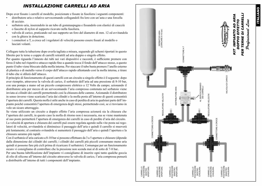
Dopo aver fissato i carrelli al modello, posizionate e fissate in fusoliera i seguenti componenti:• distributore aria e relativo servocomando collegandoli fra loro con un’asta e una forcella
di acciaio.• serbatoio aria, inserendolo in un tubo di gommaspugna e fissandolo con elastici di caucciù
o fascette di nylon al supporto ricavato nella fusoliera.• valvola di carico, praticando sul suo supporto un foro del diametro di mm. 12 ed avvitandola
con la ghiera in dotazione.• i connettori a T, a croce ed i regolatori di velocità possono essere fissati al modello o
lasciati volanti.
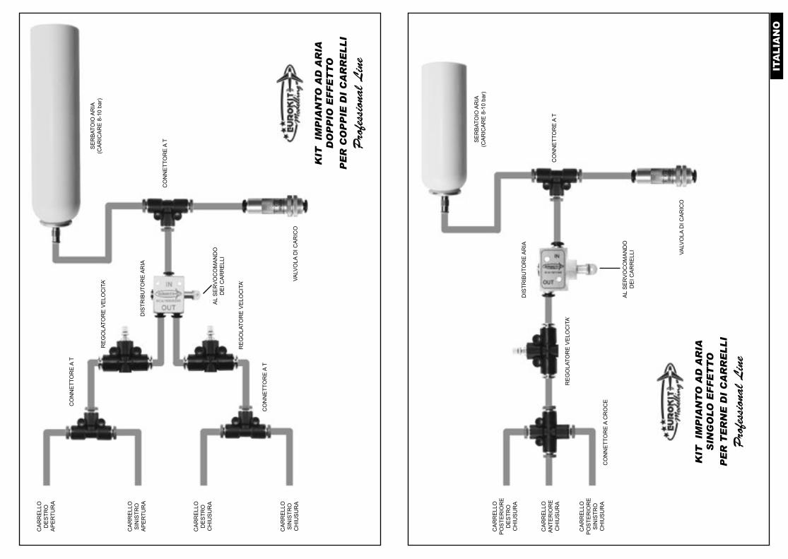
Collegare tutta la tubazione dopo averla tagliata a misura, seguendo gli schemi riportati in questo libretto per le terne o coppie di carrelli retrattili ad aria doppio o singolo effetto.Per quanto riguarda l’innesto dei tubi nei vari dispositivi e raccordi, è sufficiente premere con forza il tubo nel rispettivo attacco rapido fino a quando tocca il fondo dell’attacco stesso, a questo punto il tubo viene bloccato dalla molla interna. Per staccare il tubo basta premere l’anello esterno di plastica o di metallo verso il corpo dell’attacco rapido allentando così la molla interna, e tirare il tubo che si sfilerà dall’attacco.Il principio di funzionamento di questi carrelli con un circuito a singolo effetto è il seguente: dopo aver riempito, attraverso la valvola di carico, il serbatoio dell’aria ad una pressione di 8-10 bar, con una pompa a mano od un piccolo compressore elettrico a 12 Volts da campo; azionando il distributore aria per mezzo di un servocomando l’aria compressa contenuta nel serbatoio viene inviata ai cilindri dei carrelli permettendo così la chiusura delle camme. Azionando il distributore in senso inverso viene scaricata l’aria dai cilindri e la molla posta all’interno di questi consentirà l’apertura dei carrelli. Questa molla è utile anche in caso di perdita di aria in qualsiasi parte dell’im-pianto poiché consentirà l’apertura di emergenza degli stessi, permettendo così, se ci troviamo in volo un sicuro atterraggio.Se viene utilizzato un circuito a doppio effetto l’aria compressa azionerà sia la chiusura che l’apertura dei carrelli, in questo caso la molla di ritorno non è necessaria, ma se viene mantenuta al suo posto permetterà l’apertura di emergenza dei carrelli in caso di perdite d’aria dal circuito.La velocità di apertura e chiusura dei carrelli può essere regolata agendo sulla vite posta sui rego-latori di velocità, avvitandola si diminuisce il passaggio dell’aria e quindi il carrello si muoverà più lentamente; al contrario svitandola si aumenterà il passaggio dell’aria e quindi l’apertura e la chiusura saranno più rapidi.Con il serbatoio d’aria caricato a 8-10 bar si possono effettuare da 3 a 5 aperture e chiusure (dipende dalla dimensione dei cilindri dei carrelli; i cilindri dei carrelli più piccoli consumano meno aria quindi si possono fare più cicli prima di ricaricare il serbatoio). Comunque per un funzionamento sicuro vi consigliamo di controllare che la pressione non scenda mai al di sotto di 7-8 bar..Per una buona lubrificazione dell’impianto vi consigliamo di inserire ogni tanto qualche goccia di olio di silicone all’interno del circuito attraverso la valvola di carico, l’aria compressa penserà a distribuirlo all’interno di tutti i componenti dell’impianto.
KIT
IM
PIA
NT
O A
D A
RIA
DO
PP
IO E
FF
ET
TO
PE
R T
ER
NE
DI
CA
RR
EL
LI
Pro
fess
iona
l L
ine
AL
SE
RV
OC
OM
AN
DO
D
EI C
AR
RE
LLI
DIS
TRIB
UTO
RE
AR
IA
SE
RB
ATO
IO A
RIA
(C
AR
ICA
RE
8-1
0 ba
r)
VALV
OLA
DI C
AR
ICO
CO
NN
ETT
OR
E A
T
RE
GO
LATO
RE
VE
LOC
ITA’
CA
RR
ELL
OP
OS
TER
IOR
ES
INIS
TRO
AP
ER
TUR
A
CA
RR
ELL
OP
OS
TER
IOR
ED
ES
TRO
AP
ER
TUR
A
CA
RR
ELL
OA
NTE
RIO
RE
AP
ER
TUR
A
CA
RR
ELL
OP
OS
TER
IOR
ES
INIS
TRO
CH
IUS
UR
A
CA
RR
ELL
OP
OS
TER
IOR
ED
ES
TRO
CH
IUS
UR
A
CA
RR
ELL
OA
NTE
RIO
RE
CH
IUS
UR
A
CO
NN
ETT
OR
E A
CR
OC
E
CO
NN
ETT
OR
E A
CR
OC
E
RE
GO
LATO
RE
VE
LOC
ITA’
ITA
LIA
NO
AL
SE
RV
OC
OM
AN
DO
D
EI C
AR
RE
LLI
DIS
TRIB
UTO
RE
AR
IA
VALV
OLA
DI C
AR
ICO
RE
GO
LATO
RE
VE
LOC
ITA’
CA
RR
ELL
OS
INIS
TRO
AP
ER
TUR
A
CA
RR
ELL
OD
ES
TRO
AP
ER
TUR
A
CA
RR
ELL
OS
INIS
TRO
CH
IUS
UR
A
CA
RR
ELL
OD
ES
TRO
CH
IUS
UR
A
CO
NN
ETT
OR
E A
T
CO
NN
ETT
OR
E A
T
RE
GO
LATO
RE
VE
LOC
ITA’
KIT
IM
PIA
NT
O A
D A
RIA
DO
PP
IO E
FF
ET
TO
PE
R C
OP
PIE
DI
CA
RR
EL
LI
Pro
fess
iona
l L
ine
SE
RB
ATO
IO A
RIA
(C
AR
ICA
RE
8-1
0 ba
r)
CO
NN
ETT
OR
E A
T
AL
SE
RV
OC
OM
AN
DO
D
EI C
AR
RE
LLI
CA
RR
ELL
OP
OS
TER
IOR
ES
INIS
TRO
CH
IUS
UR
A
CA
RR
ELL
OP
OS
TER
IOR
ED
ES
TRO
CH
IUS
UR
A
CA
RR
ELL
OA
NTE
RIO
RE
CH
IUS
UR
A
KIT
IM
PIA
NT
O A
D A
RIA
SIN
GO
LO
EF
FE
TT
OP
ER
TE
RN
E D
I C
AR
RE
LL
I
Pro
fess
iona
l L
ine
DIS
TRIB
UTO
RE
AR
IA
SE
RB
ATO
IO A
RIA
(C
AR
ICA
RE
8-1
0 ba
r)
VALV
OLA
DI C
AR
ICO
CO
NN
ETT
OR
E A
T
RE
GO
LATO
RE
VE
LOC
ITA’
CO
NN
ETT
OR
E A
CR
OC
E
EN
GLI
SHINSTRUCTIONS - PRECAUTIONS
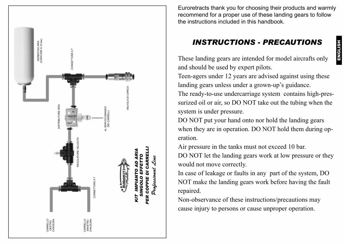
These landing gears are intended for model aircrafts only and should be used by expert pilots.Teen-agers under 12 years are advised against using these landing gears unless under a grown-up’s guidance.The ready-to-use undercarriage system contains high-pres-surized oil or air, so DO NOT take out the tubing when the system is under pressure. DO NOT put your hand onto nor hold the landing gears when they are in operation. DO NOT hold them during op-eration. Air pressure in the tanks must not exceed 10 bar.DO NOT let the landing gears work at low pressure or they would not move correctly.In case of leakage or faults in any part of the system, DO NOT make the landing gears work before having the fault repaired.Non-observance of these instructions/precautions may cause injury to persons or cause unproper operation.
Euroretracts thank you for choosing their products and warmly recommend for a proper use of these landing gears to follow the instructions included in this handbook.
CA
RR
ELL
OS
INIS
TRO
CH
IUS
UR
A
CA
RR
ELL
OD
ES
TRO
CH
IUS
UR
A
KIT
IM
PIA
NT
O A
D A
RIA
SIN
GO
LO
EF
FE
TT
OP
ER
CO
PP
IE D
I C
AR
RE
LL
I
Pro
fess
iona
l L
ine
AL
SE
RV
OC
OM
AN
DO
D
EI C
AR
RE
LLI
DIS
TRIB
UTO
RE
AR
IA
SE
RB
ATO
IO A
RIA
(C
AR
ICA
RE
8-1
0 ba
r)
VALV
OLA
DI C
AR
ICO
CO
NN
ETT
OR
E A
T
RE
GO
LATO
RE
VE
LOC
ITA’
CO
NN
ETT
OR
E A
T
EN
GLI
SH
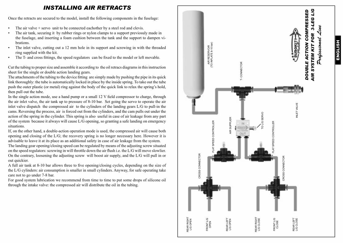
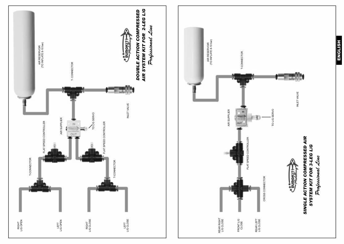
INSTALLING AIR RETRACTS
Once the retracts are secured to the model, install the following components in the fuselage:
• The air valve + servo unit to be connected eachother by a steel rod and clevis. • The air tank, securing it by rubber rings or nylon clamps to a support previosuly made in
the fuselage, and inserting a foam cushion between the tank and the support to dampen vi-brations.
• The inlet valve, cutting out a 12 mm hole in its support and screwing in with the threaded ring supplied with the kit.
• The T- and cross fittings, the speed regulators can be fixed to the model or left movable.
Cut the tubing to proper size and assemble it according to the oil retracs diagrams in this instruction sheet for the single or double action landing gears. The attachments of the tubing to the device fitting are simply made by pushing the pipe in its quick link thoroughly: the tube is automatically locked in place by the inside spring. To take out the tube push the outer plastic (or metal) ring against the body of the quick link to relax the spring’s hold, then pull out the tube. In the single action mode, use a hand pump or a small 12 V field compressor to charge, through the air inlet valve, the air tank up to pressure of 8-10 bar. Set going the servo to operate the air inlet valve dispatch the compressed air to the cylinders of the landing gears L/G to pull-in the cams. Reversing the process, air is forced out from the cylinders, and the cam pulls out under the action of the spring in the cylinder. This spring is also useful in case of air leakage from any part of the system because it always will cause L/G opening, so granting a safe landing on emergency situations. If, on the other hand, a double-action operation mode is used, the compressed air will cause both opening and closing of the L/G; the recovery spring is no longer necessary here. However it is advisable to leave it at its place as an additional safety in case of air leakage from the system. The landing gear opening/closing speed can be regulated by means of the adjusting screw situated on the speed regulators: screwing in will throttle down the air flush i.e. the L/G will move slowlier.On the contrary, loosening the adjusting screw will boost air supply, and the L/G will pull in or out quickier. A full air tank at 8-10 bar allows three to five opening/closing cycles, depending on the size of the L/G cylinders: air consumption is smaller in small cylinders. Anyway, for safe operating take care not to go under 7-8 bar.For good system lubrication we recommend from time to time to put some drops of silicone oil through the intake valve: the compressed air will distribute the oil in the tubing.
DO
UB
LE
AC
TIO
N C
OM
PR
ES
SE
D
AIR
SY
ST
EM
KIT
FO
R
3-L
EG
L/G
Pro
fess
iona
l L
ine
TO L
/G S
ER
VO
AIR
SU
PP
LIE
R
AIR
RE
SE
RV
OIR
(TO
INFL
ATE
8-1
0 ba
r)
INLE
T VA
LVE
T- C
ON
NE
CTO
R
FLAT
SP
EE
D C
ON
TRO
LLE
R
FLAT
SP
EE
D C
ON
TRO
LLE
R
RE
AR
LE
FTL/
G O
PE
N
RE
AR
RIG
HT
L/G
OP
EN
FRO
NT
L/G
OP
EN
RE
AR
LE
FTL/
G C
LOS
E
RE
AR
RIG
HT
L/G
CLO
SE
FRO
NT
L/G
CLO
SE
CR
OS
S C
ON
NE
CTO
R
CR
OS
S C
ON
NE
CTO
R
EN
GLI
SH
DO
UB
LE
AC
TIO
N C
OM
PR
ES
SE
D
AIR
SY
ST
EM
KIT
FO
R
2-L
EG
L/G
Pro
fess
iona
l L
ine
TO L
/G S
ER
VO
AIR
SU
PP
LIE
R
AIR
RE
SE
RV
OIR
(TO
INFL
ATE
8-1
0 ba
r)
INLE
T VA
LVE
T- C
ON
NE
CTO
R
FLAT
SP
EE
D C
ON
TRO
LLE
R
LEFT
L/G
OP
EN
RIG
HT
L/G
OP
EN
LEFT
L/G
CLO
SE
RIG
HT
L/G
CLO
SE
T-C
ON
NE
CTO
R
T-C
ON
NE
CTO
R
FLAT
SP
EE
D C
ON
TRO
LLE
R
TO L
/G S
ER
VO
RE
AR
LE
FTL/
G C
LOS
E
RE
AR
RIG
HT
L/G
CLO
SE
FRO
NT
L/G
CLO
SE
SIN
GL
E A
CT
ION
CO
MP
RE
SS
ED
AIR
S
YS
TE
M K
IT F
OR
3-L
EG
L/G
Pro
fess
iona
l L
ine
AIR
SU
PP
LIE
R
AIR
RE
SE
RV
OIR
(TO
INFL
ATE
8-1
0 ba
r)
INLE
T VA
LVE
T-C
ON
NE
CTO
R
FLAT
SP
EE
D C
ON
TRO
LLE
R
CR
OS
S C
ON
NE
CTO
R
FRA
NC
AIS
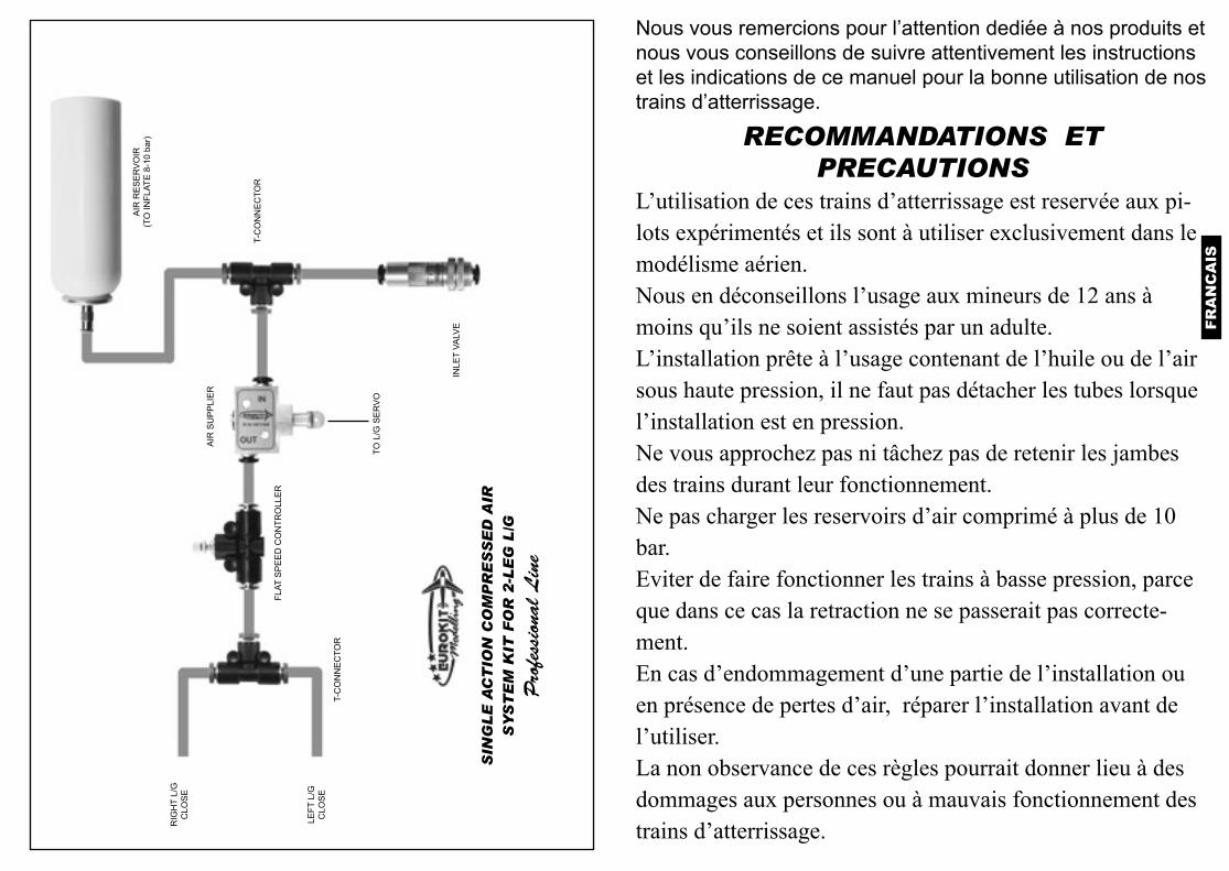
RECOMMANDATIONS ET PRECAUTIONS
L’utilisation de ces trains d’atterrissage est reservée aux pi-lots expérimentés et ils sont à utiliser exclusivement dans le modélisme aérien. Nous en déconseillons l’usage aux mineurs de 12 ans à moins qu’ils ne soient assistés par un adulte.L’installation prête à l’usage contenant de l’huile ou de l’air sous haute pression, il ne faut pas détacher les tubes lorsque l’installation est en pression. Ne vous approchez pas ni tâchez pas de retenir les jambes des trains durant leur fonctionnement.Ne pas charger les reservoirs d’air comprimé à plus de 10 bar.Eviter de faire fonctionner les trains à basse pression, parce que dans ce cas la retraction ne se passerait pas correcte-ment.En cas d’endommagement d’une partie de l’installation ou en présence de pertes d’air, réparer l’installation avant de l’utiliser.La non observance de ces règles pourrait donner lieu à des dommages aux personnes ou à mauvais fonctionnement des trains d’atterrissage.
Nous vous remercions pour l’attention dediée à nos produits et nous vous conseillons de suivre attentivement les instructions et les indications de ce manuel pour la bonne utilisation de nos trains d’atterrissage.
LEFT
L/G
CLO
SE
RIG
HT
L/G
CLO
SE
SIN
GL
E A
CT
ION
CO
MP
RE
SS
ED
AIR
S
YS
TE
M K
IT F
OR
2-L
EG
L/G
Pro
fess
iona
l L
ine
TO L
/G S
ER
VO
AIR
SU
PP
LIE
R
AIR
RE
SE
RV
OIR
(TO
INFL
ATE
8-1
0 ba
r)
INLE
T VA
LVE
T-C
ON
NE
CTO
R
FLAT
SP
EE
D C
ON
TRO
LLE
R
T-C
ON
NE
CTO
R
FRA
NC
AIS
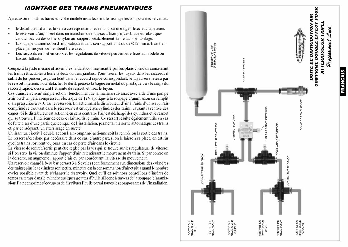
MONTAGE DES TRAINS PNEUMATIQUES
Après avoir monté les trains sur votre modèle installez dans le fuselage les composantes suivantes:
• le distributeur d’air et le servo correspondant, les reliant par une tige filetée et chape acier.• le réservoir d’air, inséré dans un manchon de mousse, à fixer par des bracelets élastiques
caoutchouc ou des colliers nylon au support préalablement taillé dans le fuselage.• la soupape d’ammission d’air, pratiquant dans son support un trou de Ø12 mm et fixant en
place par moyen de l’embout livré avec.• Les raccords en T et en croix et les régulateurs de vitesse peuvent être fixés au modèle ou
laissés flottants.
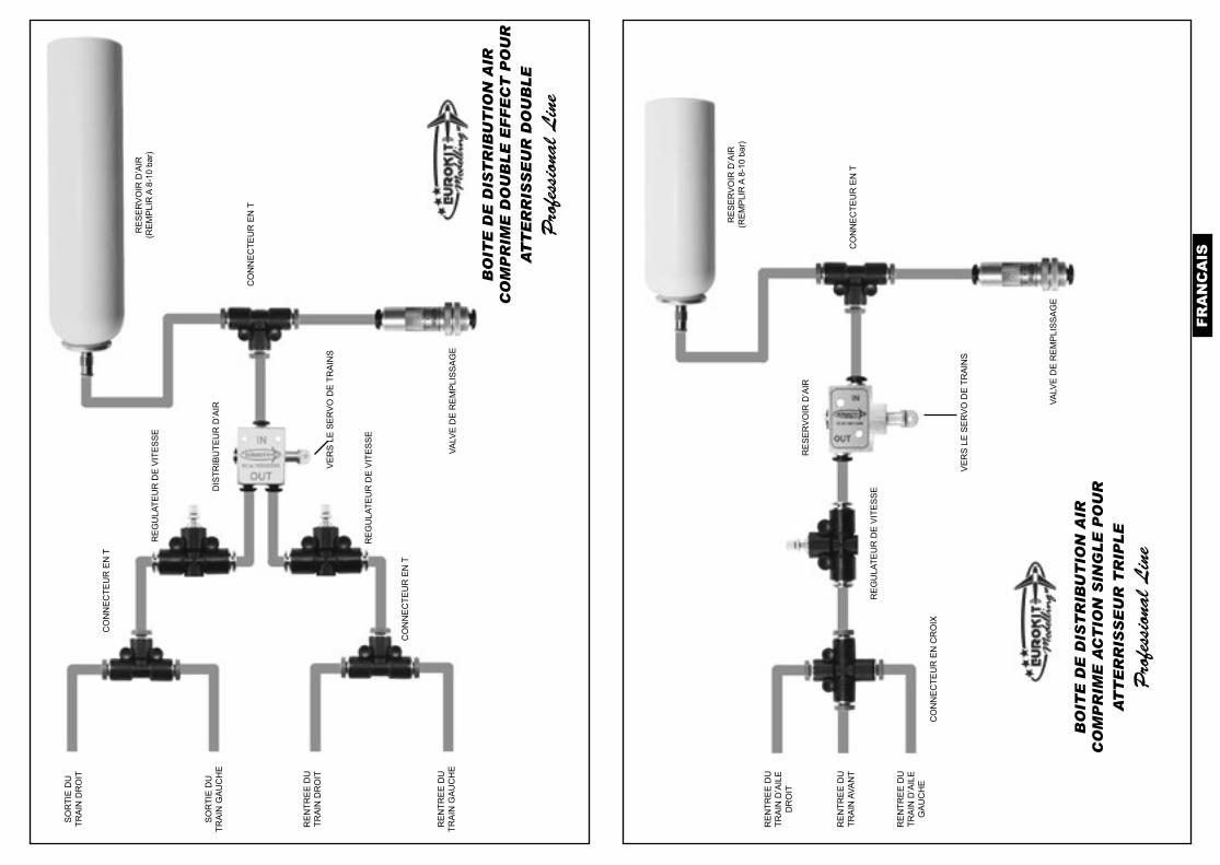
Coupez à la juste mesure et assemblez la durit comme montré par les plans ci-inclus concernant les trains rétractables à huile, à deux ou trois jambes. Pour insérer les tuyaux dans les raccords il suffit de les presser jusqu’au bout dans le raccord rapide correspondant: le tuyau sera retenu par le ressort intérieur. Pour détacher le durit, pressez la bague en métal ou plastique vers le corps du raccord rapide, desserrant l’étreinte du ressort, et tirez le tuyau.Ces trains, en circuit simple action, fonctionnent de la manière suivante: avec aide d’une pompe à air ou d’un petit compresseur électrique de 12V appliqué à la soupape d’ammission on remplit d’air pressurizé à 8-10 bar le réservoir. En actionnant le distributeur d’air à l’aide d’un servo l’air comprimé se trouvant dans le réservoir est envoyé aus cylindres des trains causant la rentrée des cames. Si le distributeur est actionné en sens contraire l’air est déchargé des cylindres et le ressort qui se trouve à l’intérieur de ceux-ci fait sortir le train. Ce ressort résulte également utile en cas de fuite d’air d’une partie quelconque de l’installation, permettant la sortie automatique des trains et, par conséquant, un attérrissage en sûreté.Utilisant un circuit à double action l’air comprimé actionne soit la rentrée ou la sortie des trains. Le ressort n’est donc pas necéssaire dans ce cas; d’autre part, si on le laisse à sa place, on est sûr que les trains sortiront toujours en cas de perte d’air dans le circuit.La vitesse de rentrée/sortie peut être réglée par la vis qui se trouve sur les régulateurs de vitesse: si l’on serre la vis on diminue l’apport d’air, relentissant le mouvement du train. Si par contre on la desserre, on augmente l’apport d’air et, par conséquant, la vitesse du mouvement.Un réservoir chargé à 8-10 bar permet 3 à 5 cycles (comformément aux dimensions des cylindres des trains; plus les cylindres sont petits, mineure est la consommation d’air et plus grand le nombrecycles possible avant de récharger le rèservoir). Quoi qu’il en soit nous conseillons d’insèrer de temps en temps dans le cylindre quelques gouttes d’huile silicone à travers de la soupape d’ammis-sion: l’air comprimé s’occupera de distribuer l’huile parmi toutes les composantes de l’installation.
BO
ITE
DE
DIS
TR
IBU
TIO
N A
IR
CO
MP
RIM
E D
OU
BL
E E
FF
EC
T P
OU
R
AT
TE
RR
ISS
EU
R T
RIP
LE
Pro
fess
iona
l L
ine
VE
RS
LE
SE
RV
O D
E T
RA
INS
DIS
TRIB
UTE
UR
D’A
IR
RE
SE
RV
OIR
D’A
IR(R
EM
PLI
R A
8-1
0 ba
r)
VALV
E D
E R
EM
PLI
SS
AG
E
CO
NN
EC
TEU
R E
N T
RE
GU
LATE
UR
DE
VIT
ES
SE
CO
NN
EC
TEU
R E
N C
RO
IX
CO
NN
EC
TEU
R E
N C
RO
IX
RE
GU
LATE
UR
DE
VIT
ES
SE
SO
RTI
E D
UTR
AIN
D’A
ILE
GA
UC
HE
SO
RTI
E D
UTR
AIN
D’A
ILE
DR
OIT
SO
RTI
E D
UTR
AIN
AVA
NT
RE
NTR
EE
DU
TRA
IN D
’AIL
EG
AU
CH
E
RE
NTR
EE
DU
TRA
IN D
’AIL
ED
RO
IT
RE
NTR
EE
DU
TRA
IN A
VAN
T
FRA
NC
AIS
BO
ITE
DE
DIS
TR
IBU
TIO
N A
IR
CO
MP
RIM
E D
OU
BL
E E
FF
EC
T P
OU
R
AT
TE
RR
ISS
EU
R D
OU
BL
E
Pro
fess
iona
l L
ine
VE
RS
LE
SE
RV
O D
E T
RA
INS
DIS
TRIB
UTE
UR
D’A
IR
RE
SE
RV
OIR
D’A
IR(R
EM
PLI
R A
8-1
0 ba
r)
VALV
E D
E R
EM
PLI
SS
AG
E
CO
NN
EC
TEU
R E
N T
RE
GU
LATE
UR
DE
VIT
ES
SE
SO
RTI
E D
UTR
AIN
GA
UC
HE
SO
RTI
E D
UTR
AIN
DR
OIT
RE
NTR
EE
DU
TRA
IN G
AU
CH
E
RE
NTR
EE
DU
TRA
IN D
RO
IT
CO
NN
EC
TEU
R E
N T
CO
NN
EC
TEU
R E
N T
RE
GU
LATE
UR
DE
VIT
ES
SE
VE
RS
LE
SE
RV
O D
E T
RA
INS
BO
ITE
DE
DIS
TR
IBU
TIO
N A
IR
CO
MP
RIM
E A
CT
ION
SIN
GL
E P
OU
R
AT
TE
RR
ISS
EU
R T
RIP
LE
Pro
fess
iona
l L
ine
RE
SE
RV
OIR
D’A
IR
RE
SE
RV
OIR
D’A
IR(R
EM
PLI
R A
8-1
0 ba
r)
VALV
E D
E R
EM
PLI
SS
AG
E
CO
NN
EC
TEU
R E
N T
RE
GU
LATE
UR
DE
VIT
ES
SE
RE
NTR
EE
DU
TRA
IN D
’AIL
EG
AU
CH
E
RE
NTR
EE
DU
TRA
IN D
’AIL
ED
RO
IT
RE
NTR
EE
DU
TRA
IN A
VAN
T
CO
NN
EC
TEU
R E
N C
RO
IX
DE
UT
SC
H
ANWEISUNGEN UND VORSICHTSMAßNAHMEN
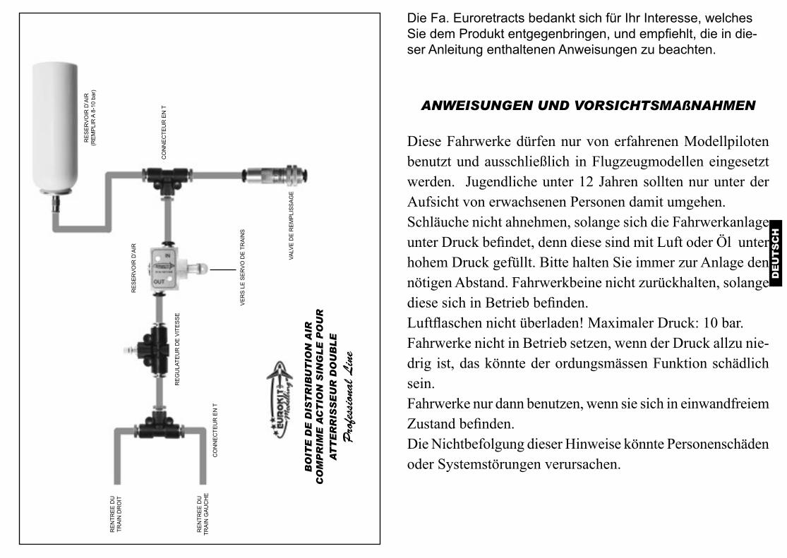
Diese Fahrwerke dürfen nur von erfahrenen Modellpiloten benutzt und ausschließlich in Flugzeugmodellen eingesetzt werden. Jugendliche unter 12 Jahren sollten nur unter der Aufsicht von erwachsenen Personen damit umgehen.Schläuche nicht ahnehmen, solange sich die Fahrwerkanlage unter Druck befindet, denn diese sind mit Luft oder Öl unter hohem Druck gefüllt. Bitte halten Sie immer zur Anlage den nötigen Abstand. Fahrwerkbeine nicht zurückhalten, solange diese sich in Betrieb befinden.Luftflaschen nicht überladen! Maximaler Druck: 10 bar.Fahrwerke nicht in Betrieb setzen, wenn der Druck allzu nie-drig ist, das könnte der ordungsmässen Funktion schädlich sein.Fahrwerke nur dann benutzen, wenn sie sich in einwandfreiem Zustand befinden.Die Nichtbefolgung dieser Hinweise könnte Personenschäden oder Systemstörungen verursachen.
Die Fa. Euroretracts bedankt sich für Ihr Interesse, welches Sie dem Produkt entgegenbringen, und empfiehlt, die in die-ser Anleitung enthaltenen Anweisungen zu beachten.
VE
RS
LE
SE
RV
O D
E T
RA
INS
BO
ITE
DE
DIS
TR
IBU
TIO
N A
IR
CO
MP
RIM
E A
CT
ION
SIN
GL
E P
OU
R
AT
TE
RR
ISS
EU
R D
OU
BL
E
Pro
fess
iona
l L
ine
RE
SE
RV
OIR
D’A
IR
VALV
E D
E R
EM
PLI
SS
AG
E
RE
GU
LATE
UR
DE
VIT
ES
SE
RE
NTR
EE
DU
TRA
IN G
AU
CH
E
RE
NTR
EE
DU
TRA
IN D
RO
IT
CO
NN
EC
TEU
R E
N T
RE
SE
RV
OIR
D’A
IR(R
EM
PLI
R A
8-1
0 ba
r)
CO
NN
EC
TEU
R E
N T
DE
UT
SC
H
LUFTFAHRWERKE
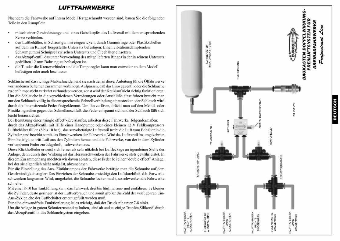
Nachdem die Fahrwerke auf Ihrem Modell festgeschraubt worden sind, bauen Sie die folgenden Teile in den Rumpf ein:
• mittels einer Gewindestange und eines Gabelkopfes das Luftventil mit dem entsprechenden Servo verbinden.
• den Luftbehälter, in Schaumgummi eingewickelt, durch Gummiringe oder Plastikschellen auf dem im Rumpf hergestellte Untersatz befestigen. Einen vibrationsdämpfenden Schaumgummi Schnipsel zwischen Untersatz und Ölbehälter einsetzen.
• das Abzapfventil, das unter Verwendung des mitgelieferten Ringes in der in seinem Untersatz gedrillten 12 mm Bohrung zu befestigen ist.
• die T- oder die Kreuzverbinder und die Temporegler kann man entweder an dem Modell befestigen oder auch lose lassen.
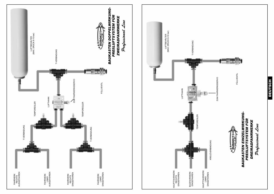
Schläuche auf das richtige Maß schneiden und sie nach den in dieser Anleitung für die Ölfahrwerke vorhandenen Schemen zusammen verbinden. Aufpassen, daß das Einwegventil oder die Schläuche zu der Pumpe nicht verkehrt verbunden werden, sonst wird der Kreislauf nicht richtig funktionieren. Um die Schläuche in die verschiedenen Verrohrungen oder Anschlüße einzuführen braucht man nur den Schlauch völlig in die entsprechende Schnellverbindung einzustecken: der Schlauch wird durch die innensitzende Feder festgeklemmt. Um ihn zu lösen, drückt man auf den Metall- oder Plastikring außen gegen den Schnellanschluß: die Feder entspannt sich und der Schlauch läßt sich leicht herausziehen.Bei Benutzung eines “single effect”-Kreislaufes, arbeiten diese Fahrwerke folgendermaßen: durch das Abzapfventil, mit Hilfe einer Handpumpe oder eines kleinen 12 V Feldkompressors Luftbehälter füllen (8 bis 10 bar); das servobetätigte Luftventil treibt die Luft vom Behälter in die Zylinder, und bewirkt somit das Einschwenken der Fahrwerke. Wird das Luftventil im umgekehrten Sinn betätigt, so tritt Luft aus den Zylindern heraus und die Fahrwerke, von der in dem Zylinder vorhandenen Feder zurückgeholt, schwenken aus.Diese Rückholfeder erweist sich ferner als sehr nützlich bei Luftleckage an irgendeiner Stelle der Anlage, denn durch ihre Wirkung ist das Herausschwenken der Fahrwerke stets gewährleistet. In diesem Zusammenhang möchten wir davon abraten, diese Feder bei einer “double effect” Anlage, bei der sie eigentlich nicht nötig ist, abzunehmen.Für die Einstellung des Aus- Einfahrtempos der Fahrwerke betätige man die Schraube auf dem Geschwindigkeitsregler: Das Einziehen der Schraube erniedrigt den Luftdurchfluß, d.h. Farwerke schwenken langsamer. Wird, umgekehrt, die Schraube locker macht, so schwenken die Fahrwerke schneller.Mit einer 8-10 bar Tankfüllung kann das Fahrwerk drei bis fünfmal aus- und einfahren. Je kleiner die Zylinder, desto geringer ist der Luftverbrauch und somit größer die Zahl der verfügbaren Ein-Aus-Zyklen ehe der Luftbehälter erneut gefüllt werden muß.Für eine einwandfreie Funktionierung ist es wichtig, daß der Druck nie unter 7-8 sinkt.Um die Anlage in gutem Schmierzustand zu halten, sind ab und zu einige Tropfen Silikonöl durch das Abzapfventil in das Schlauchsystem eingeben.
BA
UK
AS
TE
N D
OP
PE
LW
IRK
UN
G-
PR
Eß
LU
FT
SY
ST
EM
FÜ
R
DR
EIR
AD
FAH
RW
ER
KE
Pro
fess
iona
l L
ine
ZUM
FA
HR
WE
RK
SS
ER
VO
LUFT
HA
HN
LUFT
BE
HÄ
LTE
R(M
AX
. DR
UC
K 8
-10
bar)
FÜLL
VE
NTI
L
T-V
ER
BIN
DU
NG
TEM
PO
RE
GLE
R
KR
EU
ZVE
RB
IND
UN
G
KR
EU
ZVE
RB
IND
UN
G
TEM
PO
RE
GLE
R
HA
UP
TFA
HR
WE
RK
LIN
KS
AU
SG
EFA
HR
EN
HA
UP
TFA
HR
WE
RK
RE
CH
TSA
US
GE
FAH
RE
N
BU
GFA
HR
WE
RK
AU
SG
EFA
HR
EN
HA
UP
TFA
HR
WE
RK
LIN
KS
EIN
GE
FAH
RE
N
HA
UP
TFA
HR
WE
RK
RE
CH
TSE
ING
EFA
HR
EN
BU
GFA
HR
WE
RK
EIN
GE
FAH
RE
N
DE
UT
SC
H
BA
UK
AS
TE
N D
OP
PE
LW
IRK
UN
G-
PR
Eß
LU
FT
SY
ST
EM
FÜ
R
ZW
EIR
AD
FAH
RW
ER
KE
Pro
fess
iona
l L
ine
ZUM
FA
HR
WE
RK
SS
ER
VO
LUFT
HA
HN
FÜLL
VE
NTI
L
T-V
ER
BIN
DU
NG
TEM
PO
RE
GLE
R
T-V
ER
BIN
DU
NG
T-V
ER
BIN
DU
NG
TEM
PO
RE
GLE
R
FAH
RW
ER
KLI
NK
SA
US
GE
FAH
RE
N
FAH
RW
ER
KR
EC
HTS
AU
SG
EFA
HR
EN
FAH
RW
ER
KLI
NK
SE
ING
EFA
HR
EN
FAH
RW
ER
KR
EC
HTS
EIN
GE
FAH
RE
N
LUFT
BE
HÄ
LTE
R(M
AX
. DR
UC
K 8
-10
bar)
ZUM
FA
HR
WE
RK
SS
ER
VO
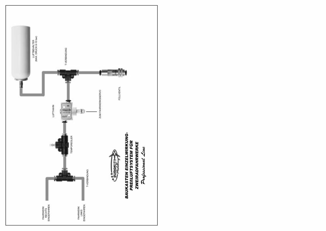
BA
UK
AS
TE
N E
INZ
ELW
IRK
UN
G-
PR
Eß
LU
FT
SY
ST
EM
FÜ
R
DR
EIR
AD
FAH
RW
ER
KE
Pro
fess
iona
l L
ine
LUFT
HA
HN
LUFT
BE
HÄ
LTE
R(M
AX
. DR
UC
K 8
-10
bar)
FÜLL
VE
NTI
L
T-V
ER
BIN
DU
NG
TEM
PO
RE
GLE
R
HA
UP
TFA
HR
WE
RK
LIN
KS
EIN
GE
FAH
RE
N
HA
UP
TFA
HR
WE
RK
RE
CH
TSE
ING
EFA
HR
EN
BU
GFA
HR
WE
RK
EIN
GE
FAH
RE
N
KR
EU
ZVE
RB
IND
UN
G
ZUM
FA
HR
WE
RK
SS
ER
VO
BA
UK
AS
TE
N E
INZ
ELW
IRK
UN
G-
PR
Eß
LU
FT
SY
ST
EM
FÜ
R
ZW
EIR
AD
FAH
RW
ER
KE
Pro
fess
iona
l L
ine
LUFT
HA
HN
LUFT
BE
HÄ
LTE
R(M
AX
. DR
UC
K 8
-10
bar)
FÜLL
VE
NTI
L
T-V
ER
BIN
DU
NG
TEM
PO
RE
GLE
R
FAH
RW
ER
KLI
NK
SE
ING
EFA
HR
EN
FAH
RW
ER
KR
EC
HTS
EIN
GE
FAH
RE
N
T-V
ER
BIN
DU
NG

EuroretractsVia Enrico Fermi 47
51010 Massa e CozzilePistoia - ITALY
Tel./Fax +39 0572 770899email: [email protected]
Per aggiornamenti su nuovi prodotti, cataloghi, istruzioni consultate regolar-mente i nostri siti web: www.euroretracts.it - www.eurokitshop.it
For new product updating, catalogues, instructions please visit our web sites: www.euroretracts.it - www.eurokitshop.it
Prenez vision des nouveautés, catalogues, notices en consultant notre pages web: www.euroretracts.it - www.eurokitshop.it
Besuchen Sie uns bitte unter www.euroretracts.it - www.eurokitshop.it, um Einsicht in unsere neuen Produkte, Kataloge, Informationen zu nehmen.
November 2014 revision