Embed Size (px)
Citation preview
8/10/2019 Lec 05 Road Material
http://slidepdf.com/reader/full/lec-05-road-material 1/29
Highway Material
. Dr. Attaullah Shah
Transportation Engineering - I
8/10/2019 Lec 05 Road Material
http://slidepdf.com/reader/full/lec-05-road-material 2/29
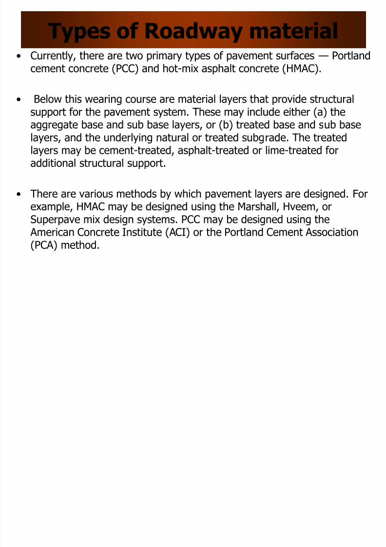
Types of Roadway material• Currently, there are two primary types of pavement surfaces — Portland
cement concrete (PCC) and hot-mix asphalt concrete (HMAC).
• Below this wearing course are material layers that provide structuralsupport for the pavement system. These may include either (a) theaggregate base and sub base layers, or (b) treated base and sub base
layers, and the underlying natural or treated subgrade. The treatedlayers may be cement-treated, asphalt-treated or lime-treated foradditional structural support.
• There are various methods by which pavement layers are designed. Forexample, HMAC may be designed using the Marshall, Hveem, orSuperpave mix design systems. PCC may be designed using the
American Concrete Institute (ACI) or the Portland Cement Association(PCA) method.
8/10/2019 Lec 05 Road Material
http://slidepdf.com/reader/full/lec-05-road-material 3/29
Hot-Mix Asphalt Concrete• HMAC consists primarily of mineral aggregates, asphalt cement (or
binder), and air.
• It is important to have suitable proportions of asphalt cement andaggregates in HMAC so as to develop mixtures that have desirableproperties associated with good performance.
• These performance measures include the resistance to the three primaryHMAC distresses: permanent deformation, fatigue cracking, and low
temperature cracking.• Permanent deformation refers to the plastic deformation of HMAC under
repeated loads. This permanent deformation can be in the form of rutting(lateral plastic flow in the wheel paths) or consolidation (furthercompaction of the HMAC after construction).
• Aggregate interlock is the primary component that resists permanentdeformation with the asphalt cement playing only a minor role. Angular,rough-textured aggregates will help reduce permanent deformation. To asignificantly lesser extent, a stiffer asphalt cement may also providesome minor benefit.
8/10/2019 Lec 05 Road Material
http://slidepdf.com/reader/full/lec-05-road-material 4/29
• Cracking can be subdivided into two broad categories: loadassociated cracking and non-load associated cracking. Loadassociated cracking has traditionally been called fatigue cracking. Inthis scenario, repeated stress applications below the maximumtensile strength of the material eventually lead to cracking.
• Factors associated with the development of fatigue cracking includethe in-situ properties of the structural section, asphalt cement,temperature, and traffic.
• Non-load associated cracking has traditionally been called low-temperature cracking. During times of rapid cooling and lowtemperatures, the stress experienced by the HMAC may exceed itsfracture strength. This leads to immediate cracking.
8/10/2019 Lec 05 Road Material
http://slidepdf.com/reader/full/lec-05-road-material 5/29
Aggregates Specification and test• Traditional aggregate specifications for HMA include the American
Association of State Highway and Transportation Officials (AASHTO)
M29 (ASTM D1073) ―Standard Method of Test for Fine Aggregate for • Bituminous Paving Mixtures,
• ‖ ASTM D692 ―Standard Specification for Coarse Aggregate forBituminous Paving Mixtures,‖ and
• ASTM D242 ―Standard Specification for Mineral Filler for BituminousPaving Mixtures.‖
• The quality of aggregates depend on the following:
– coarse aggregate angularity
– fine aggregate angularity
– flat, elongated particles, and – clay content
8/10/2019 Lec 05 Road Material
http://slidepdf.com/reader/full/lec-05-road-material 6/29
Asphalt Cement Specification and Tests
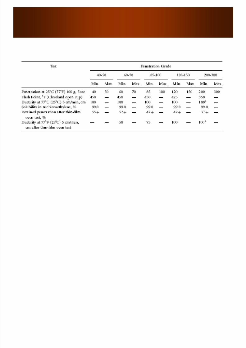
• Penetration Grading System
• ASTM D946 ―Standard Specification for Penetration-Graded Asphalt
Cement for Use in Pavement Construction‖ • This specification includes five penetration grades ranging from a
hard asphalt graded at ―40-50‖ to a soft asphalt cement graded at ―200-300.‖ The sections below discuss the tests used to classifypenetration grades
• Following tests conducted to classify the penetration grades:• Penetration Test: AASHTO T49 (ASTM D5) ―Standard Method of Test for
Penetration of Bituminous Mixtures‖ In this procedure, a needle is typicallyloaded with a 100-g weight and allowed to penetrate into an asphaltcement sample for 5 sec. Prior to conducting the test, the asphalt cementsample is brought to the testing temperature, typically 258C (778F).
• Flash Point Test ( ASTM D92) ―Standard Method of Test for Flash and FirePoints by Cleveland Open Cup‖ In this procedure, a brass cup partially filledwith asphalt cement is heated at a given rate. A flame is passed over thesurface of this cup periodically and the temperature at which this flame
causes an instantaneous flash is reported as the flash point.
8/10/2019 Lec 05 Road Material
http://slidepdf.com/reader/full/lec-05-road-material 7/29
• Ductility Test Ductility is the number of centimeters a standard briquetteof asphalt cement will stretch before breaking.
• This property is determined using AASHTO T51 (ASTM D113) ―StandardMethod of Test for Ductility of Bituminous Mixtures‖ (AASHTO, 2003).
• Solubility Test Solubility is the percentage of an asphalt cement samplethat will dissolve in trichloroethylene. This property is determined using AASHTO T44 (ASTM D2042) ―Standard Method of Test for Solubility ofBituminous Materials‖ (AASHTO, 2003).
• Thin-Film Oven Test The TFO test is used to approximate the effect ofshort-term aging during the mixing process. This test is conducted using AASHTO T179 (ASTM D1754) ―Standard Method of Test for Effect of Heatand Air on Asphalt Materials (Thin-Film Oven Test)‖ (AASHTO, 2003).
• Absolute and Kinematic Viscosity Tests: Viscosity can be defined as afluid’s resistance to flow. In the asphalt paving industry, two tests are usedto measure viscosity — absolute and kinematic viscosity tests. Absoluteviscosity is determined using AASHTO T202 (ASTM D2171) ―StandardMethod of Test for Viscosity of Asphalt by Vacuum Capillary Viscometer‖(AASHTO, 2003). Kinematic viscosity is determined using AASHTO T201(ASTM D2170) ―Standard Method of Test for Kinematic Viscosity of Asphalts
(Bitumen)‖ (AASHTO, 2003).
8/10/2019 Lec 05 Road Material
http://slidepdf.com/reader/full/lec-05-road-material 8/29
8/10/2019 Lec 05 Road Material
http://slidepdf.com/reader/full/lec-05-road-material 9/29
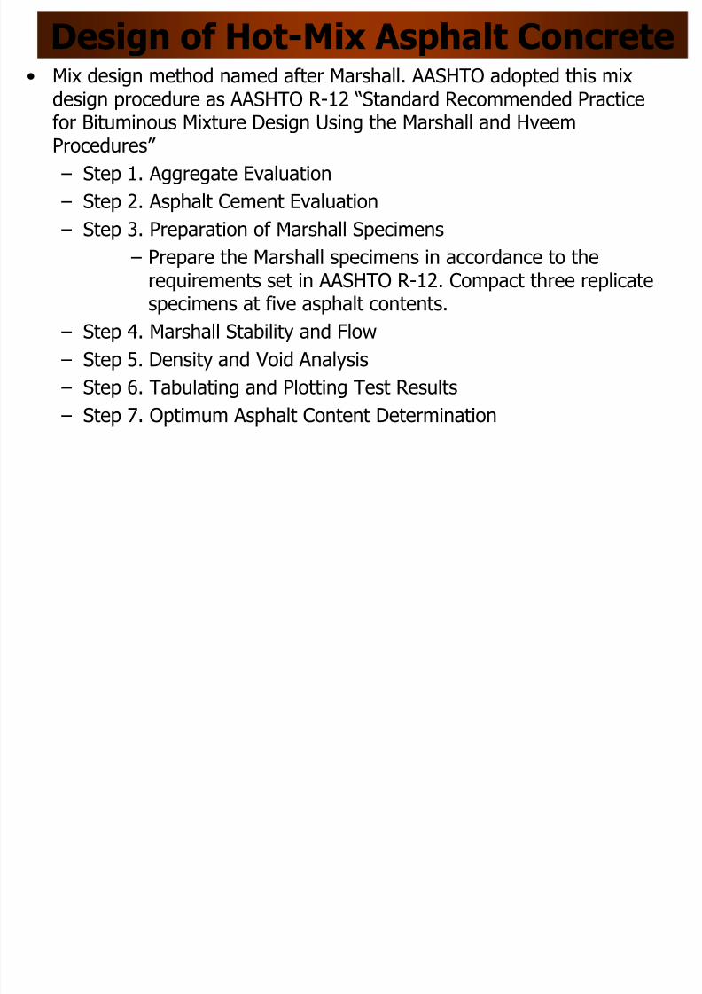
Design of Hot-Mix Asphalt Concrete
• Mix design method named after Marshall. AASHTO adopted this mixdesign procedure as AASHTO R-12 ―Standard Recommended Practice
for Bituminous Mixture Design Using the Marshall and HveemProcedures‖
– Step 1. Aggregate Evaluation
– Step 2. Asphalt Cement Evaluation
– Step 3. Preparation of Marshall Specimens
– Prepare the Marshall specimens in accordance to therequirements set in AASHTO R-12. Compact three replicatespecimens at five asphalt contents.
– Step 4. Marshall Stability and Flow
– Step 5. Density and Void Analysis – Step 6. Tabulating and Plotting Test Results
– Step 7. Optimum Asphalt Content Determination
8/10/2019 Lec 05 Road Material
http://slidepdf.com/reader/full/lec-05-road-material 10/29
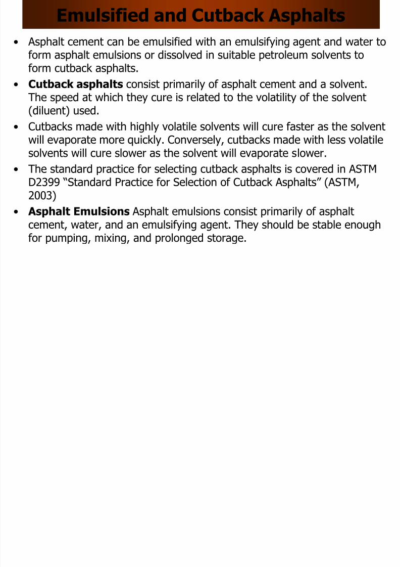
Emulsified and Cutback Asphalts
• Asphalt cement can be emulsified with an emulsifying agent and water toform asphalt emulsions or dissolved in suitable petroleum solvents to
form cutback asphalts.• Cutback asphalts consist primarily of asphalt cement and a solvent.
The speed at which they cure is related to the volatility of the solvent(diluent) used.
• Cutbacks made with highly volatile solvents will cure faster as the solvent
will evaporate more quickly. Conversely, cutbacks made with less volatilesolvents will cure slower as the solvent will evaporate slower.
• The standard practice for selecting cutback asphalts is covered in ASTMD2399 ―Standard Practice for Selection of Cutback Asphalts‖ (ASTM,2003)
• Asphalt Emulsions Asphalt emulsions consist primarily of asphaltcement, water, and an emulsifying agent. They should be stable enoughfor pumping, mixing, and prolonged storage.
8/10/2019 Lec 05 Road Material
http://slidepdf.com/reader/full/lec-05-road-material 11/29
Pavement Distresses and Performance
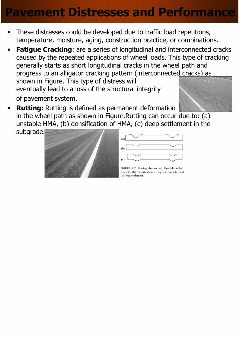
• These distresses could be developed due to traffic load repetitions,
temperature, moisture, aging, construction practice, or combinations.• Fatigue Cracking: are a series of longitudinal and interconnected cracks
caused by the repeated applications of wheel loads. This type of crackinggenerally starts as short longitudinal cracks in the wheel path andprogress to an alligator cracking pattern (interconnected cracks) as
shown in Figure. This type of distress willeventually lead to a loss of the structural integrity
of pavement system.
• Rutting: Rutting is defined as permanent deformationin the wheel path as shown in Figure.Rutting can occur due to: (a)
unstable HMA, (b) densification of HMA, (c) deep settlement in thesubgrade.

8/10/2019 Lec 05 Road Material
http://slidepdf.com/reader/full/lec-05-road-material 12/29

8/10/2019 Lec 05 Road Material
http://slidepdf.com/reader/full/lec-05-road-material 13/29
Traffic Flow
• Complex: between vehicles and drivers,among vehicles
• Stochastic: variability in outcome, cannotpredict with certainty
• Theories and models
– Macroscopic: aggregate, steady state
– Microscopic: disaggregate, dynamics
– Human factor: driver behavior
8/10/2019 Lec 05 Road Material
http://slidepdf.com/reader/full/lec-05-road-material 14/29
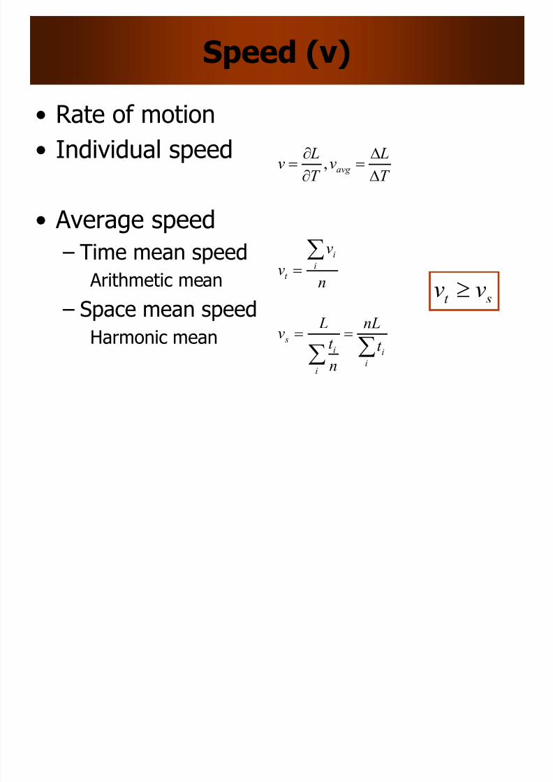
Speed (v)
• Rate of motion
• Individual speed
• Average speed
– Time mean speed
Arithmetic mean – Space mean speed
Harmonic mean
T
Lv
T
Lv avg
,
n
v
v i
i
t
i
i
i
i s
t
nL
n
t
Lv
st vv
8/10/2019 Lec 05 Road Material
http://slidepdf.com/reader/full/lec-05-road-material 15/29
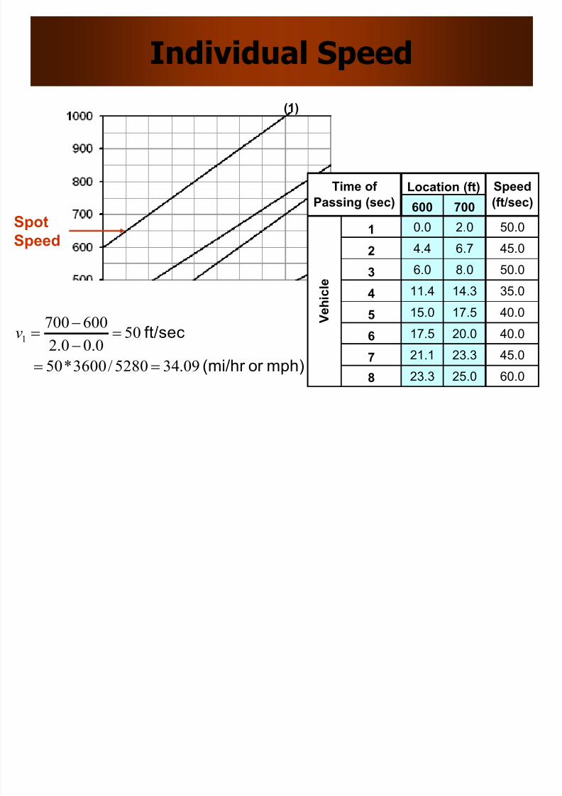
Individual Speed
600 700
1 0.0 2.0 50.0
2 4.4 6.7 45.0
3 6.0 8.0 50.0
4 11.4 14.3 35.0
5 15.0 17.5 40.0
6 17.5 20.0 40.0
7 21.1 23.3 45.0
8 23.3 25.0 60.0
Location (ft)
V e h i c
l e
Time of
Passing (sec)
Speed
(ft/sec)
(1)
Spot
Speed
mph)or (mi/hr
ft/sec
09.345280/3600*50
500.00.2
6007001
v
8/10/2019 Lec 05 Road Material
http://slidepdf.com/reader/full/lec-05-road-material 16/29
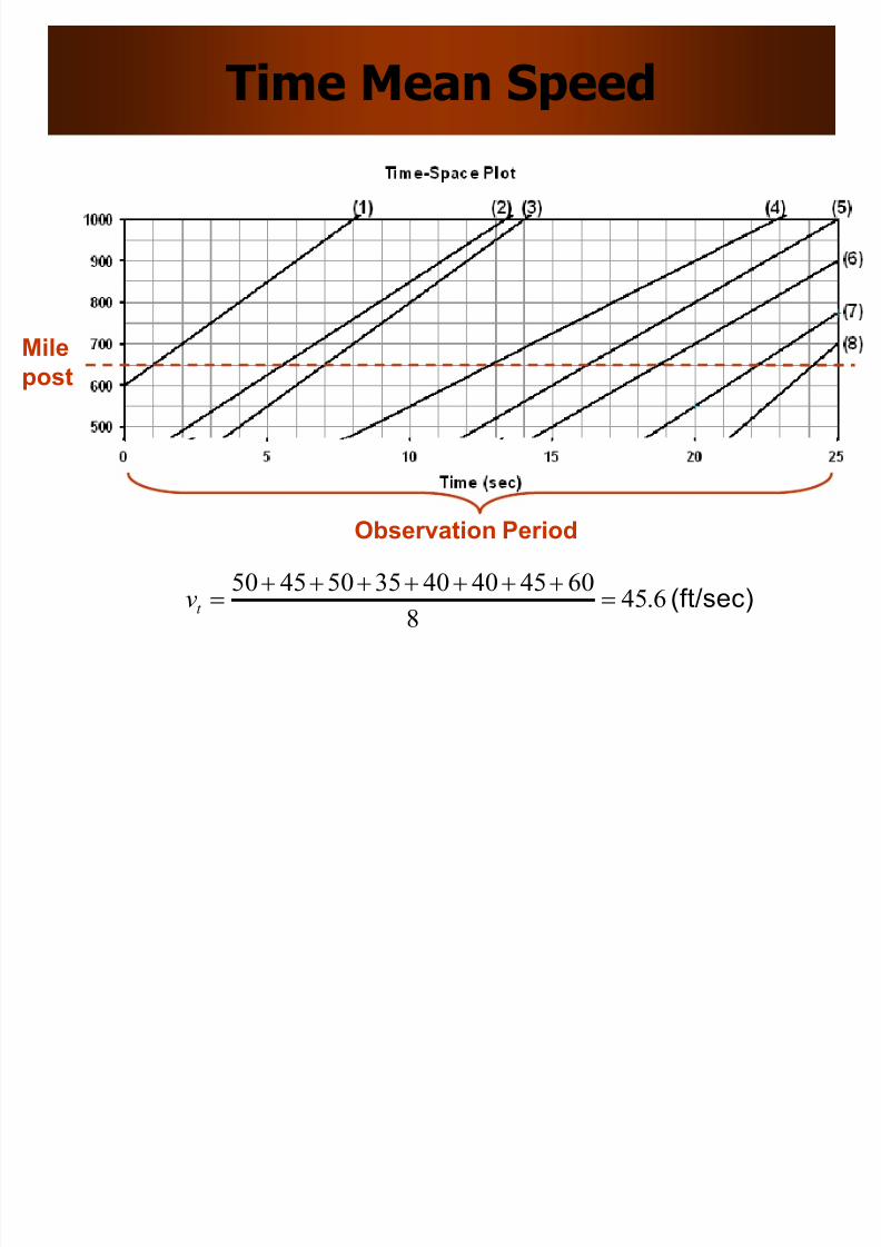
Time Mean Speed
Mile
post
Observation Period
(ft/sec)6.458
6045404035504550
t v

8/10/2019 Lec 05 Road Material
http://slidepdf.com/reader/full/lec-05-road-material 17/29
Space Mean Speed
Observation Period
(mi/hr)(ft/sec) 130244
7.12.25.25.29.223.22
8*100..v s
O b
s e r v a t i o n D i s t a n c e
8/10/2019 Lec 05 Road Material
http://slidepdf.com/reader/full/lec-05-road-material 18/29
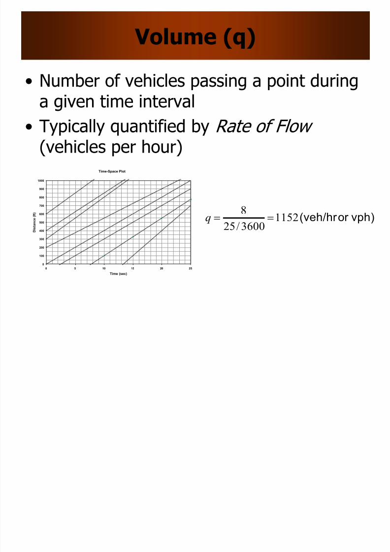
Volume (q)
• Number of vehicles passing a point duringa given time interval
• Typically quantified by Rate of Flow (vehicles per hour)
vph)or (veh/hr 11523600/25
8q
Time-Space Plot
0
100
200
300
400
500
600
700
800
900
1000
0 5 10 15 20 25
Time (sec)
D i s t a n c e
( f t )
8/10/2019 Lec 05 Road Material
http://slidepdf.com/reader/full/lec-05-road-material 19/29
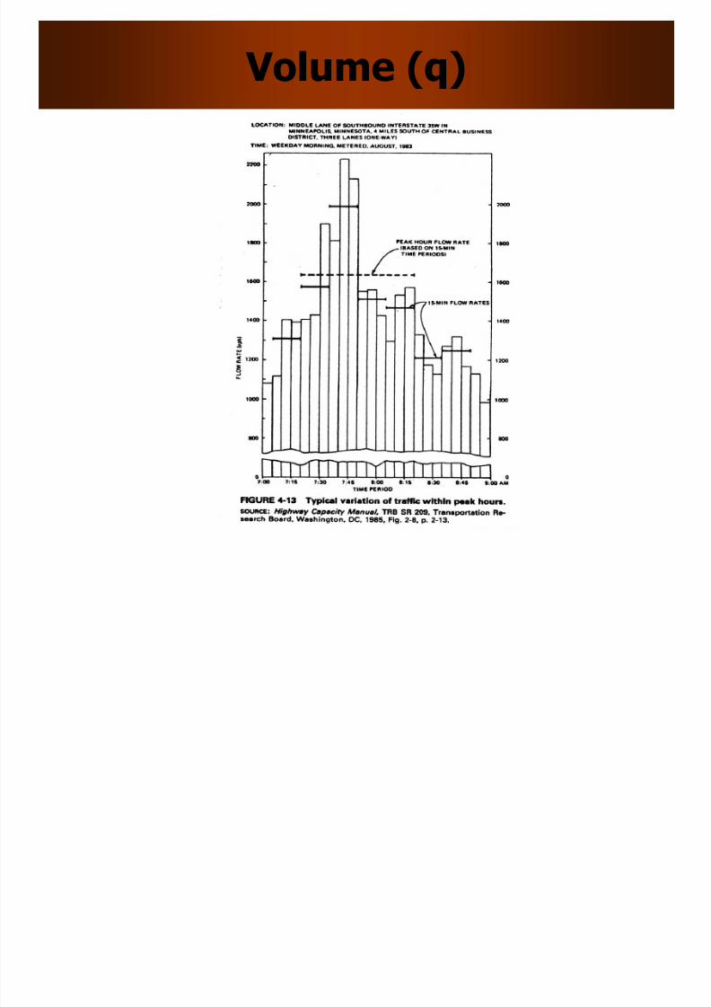
Volume (q)
8/10/2019 Lec 05 Road Material
http://slidepdf.com/reader/full/lec-05-road-material 20/29
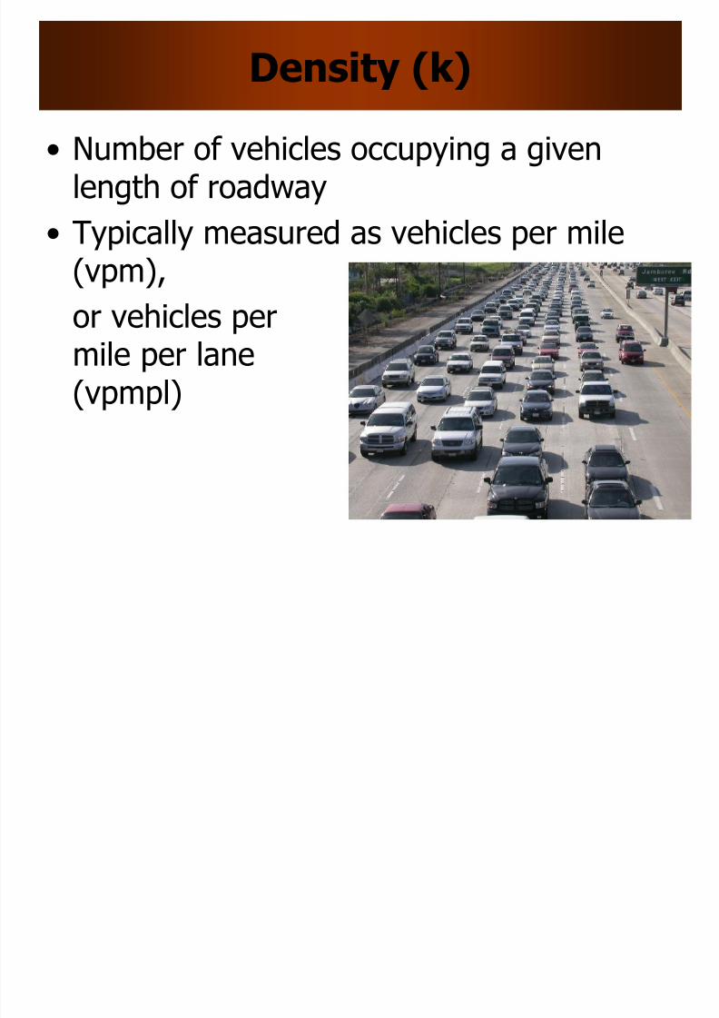
Density (k)
• Number of vehicles occupying a givenlength of roadway
• Typically measured as vehicles per mile(vpm),
or vehicles permile per lane(vpmpl)
8/10/2019 Lec 05 Road Material
http://slidepdf.com/reader/full/lec-05-road-material 21/29
Density (k)
8/10/2019 Lec 05 Road Material
http://slidepdf.com/reader/full/lec-05-road-material 22/29
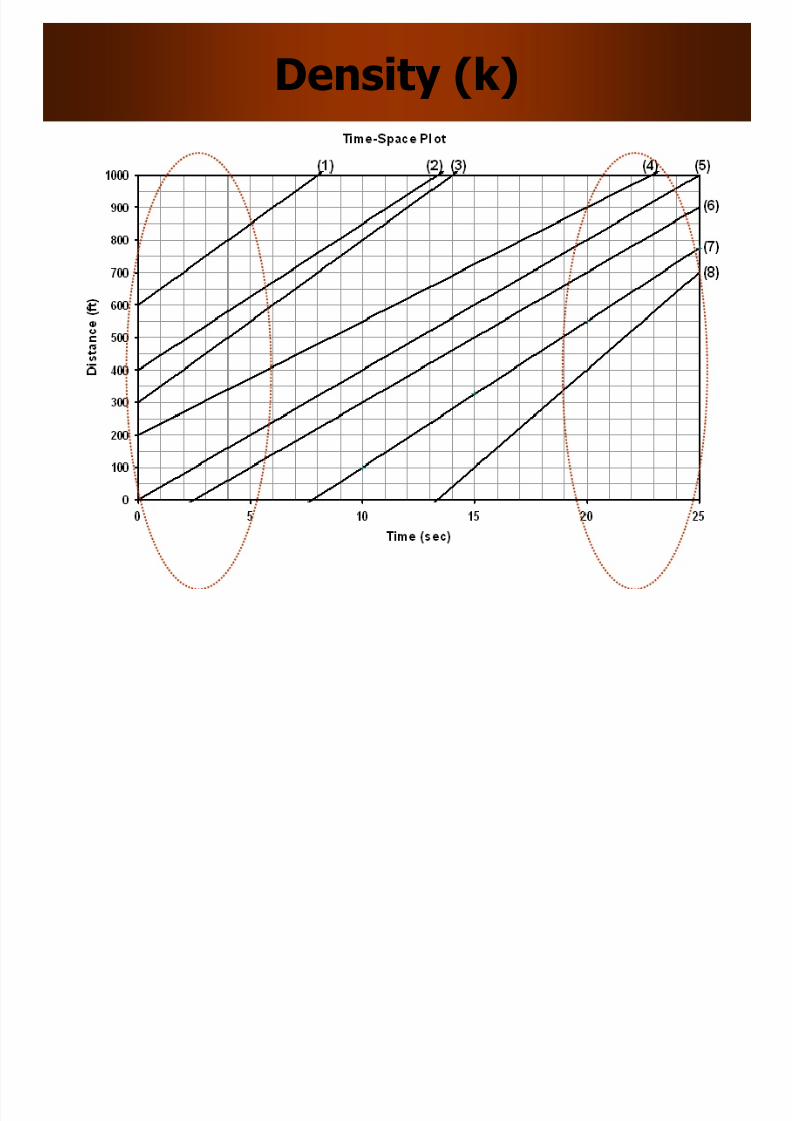
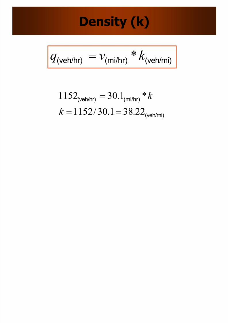
Density (k)
(veh/mi)(mi/hr)(veh/hr) k vq *
(veh/mi)
(mi/hr)(veh/hr)
22.381.30/1152
*1.301152
k
k
8/10/2019 Lec 05 Road Material
http://slidepdf.com/reader/full/lec-05-road-material 23/29
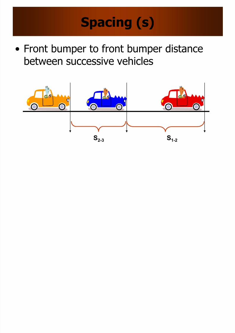
Spacing (s)
• Front bumper to front bumper distancebetween successive vehicles
S1-2 S2-3
8/10/2019 Lec 05 Road Material
http://slidepdf.com/reader/full/lec-05-road-material 24/29
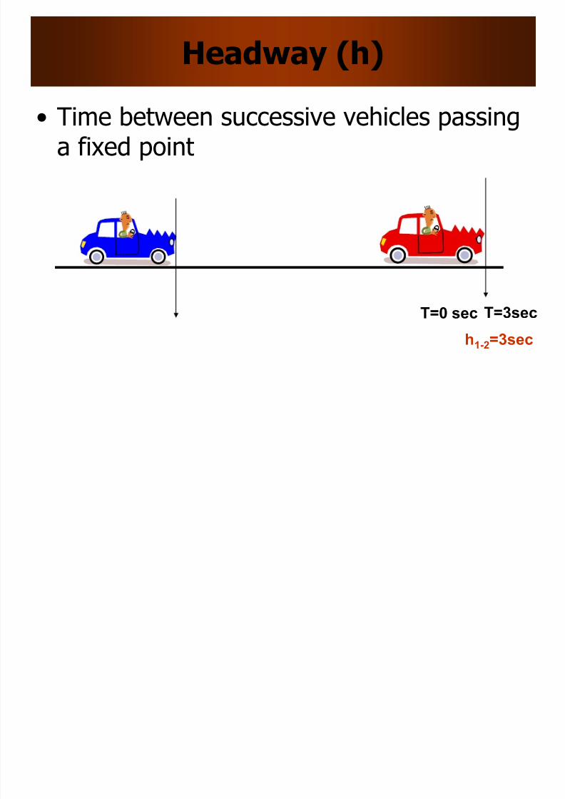
T=3sec
Headway (h)
• Time between successive vehicles passinga fixed point
T=0 sec
h1-2=3sec
8/10/2019 Lec 05 Road Material
http://slidepdf.com/reader/full/lec-05-road-material 25/29
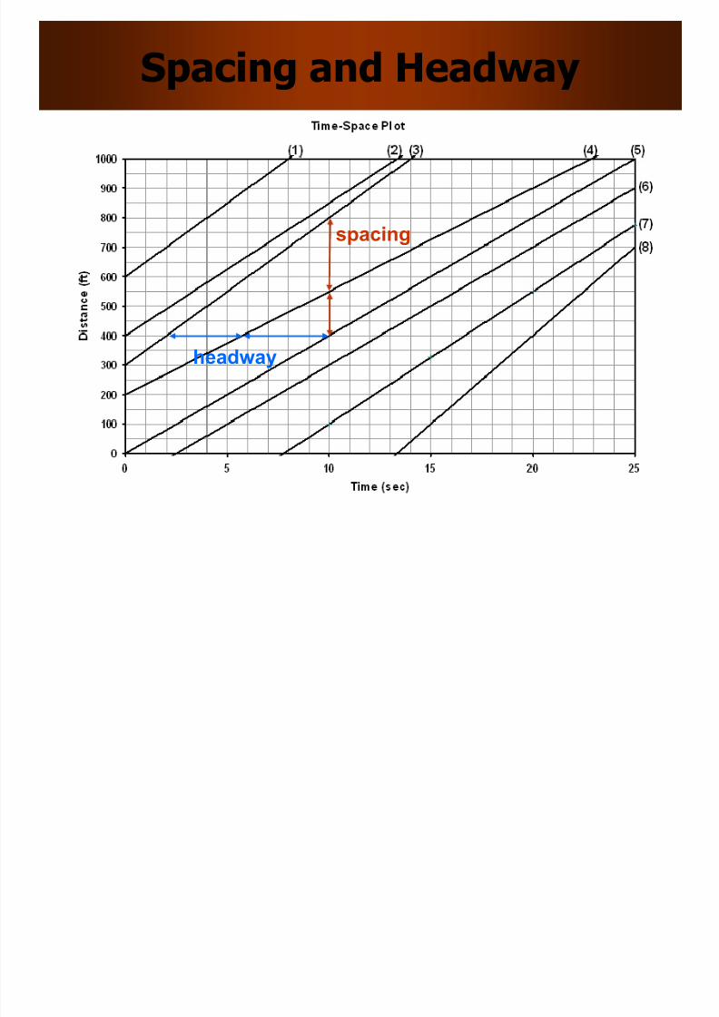
Spacing and Headway
spacing
headway
8/10/2019 Lec 05 Road Material
http://slidepdf.com/reader/full/lec-05-road-material 26/29
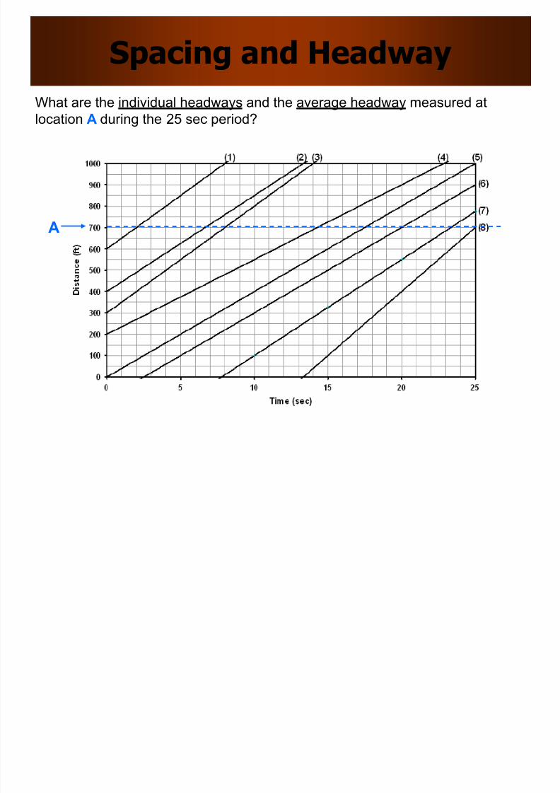
Spacing and Headway
A
What are the individual headways and the average headway measured atlocation A during the 25 sec period?
8/10/2019 Lec 05 Road Material
http://slidepdf.com/reader/full/lec-05-road-material 27/29
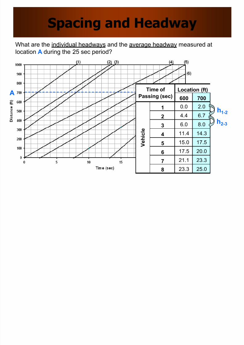
Spacing and Headway
A
What are the individual headways and the average headway measured atlocation A during the 25 sec period?
600 700
1 0.0 2.0
2 4.4 6.7
3 6.0 8.0
4 11.4 14.3
5 15.0 17.5
6 17.5 20.0
7 21.1 23.3
8 23.3 25.0
Location (ft)
V e h i c l e
Time of
Passing (sec)
h1-2
h2-3
8/10/2019 Lec 05 Road Material
http://slidepdf.com/reader/full/lec-05-road-material 28/29
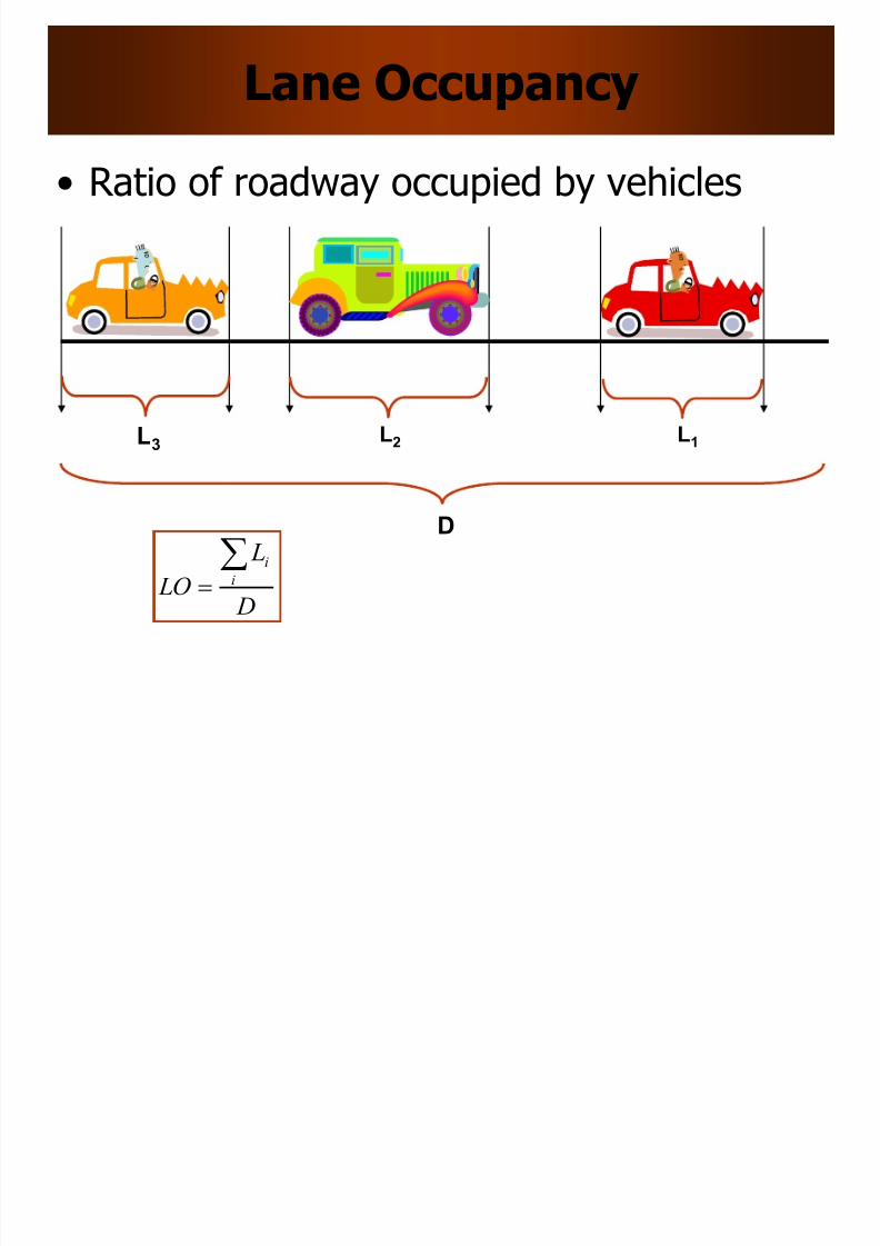
Lane Occupancy
• Ratio of roadway occupied by vehicles
L1 L2 L3
D
D
L
LO i
i
8/10/2019 Lec 05 Road Material
http://slidepdf.com/reader/full/lec-05-road-material 29/29
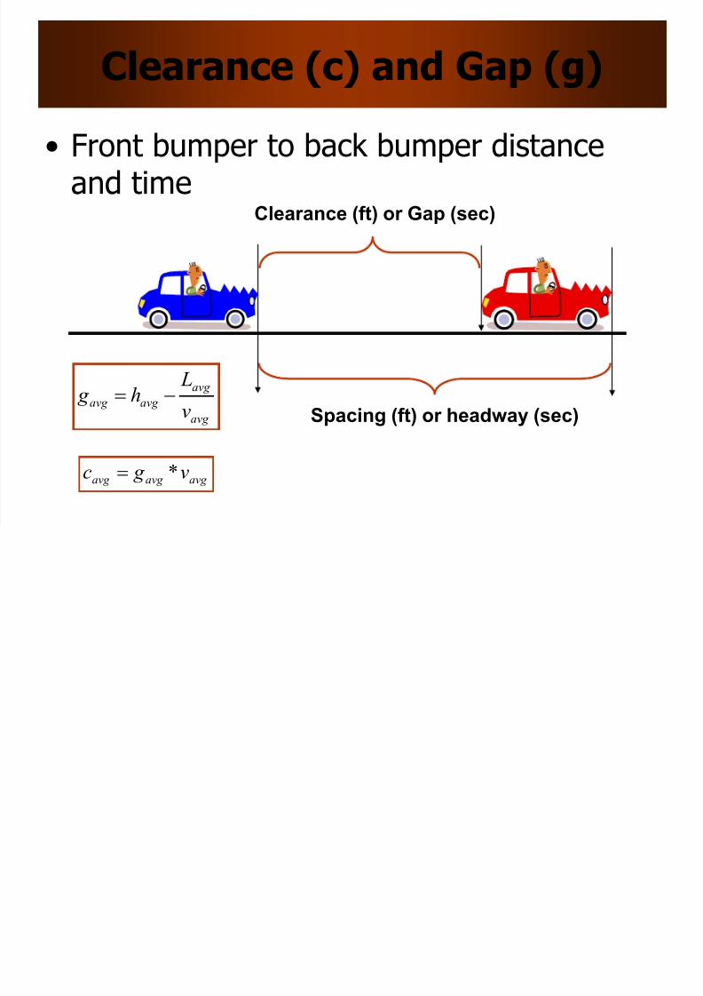
Clearance (c) and Gap (g)
• Front bumper to back bumper distanceand time
Spacing (ft) or headway (sec)
Clearance (ft) or Gap (sec)
avg
avg
avg avg v
Lh g
avg avg avg v g c *