Embed Size (px)
Citation preview
Rapport d’année sabbatique
Maillage de surfaces CAO sur processeurs multi-cœurs
Patrick Laug
École Polytechnique de Montréal, Québec, Canada
1er septembre 2014 – 31 août 2015
1 Introduction
Ce rapport présente les principales actions menées durant mon année sabbatiquequi s’est déroulée à l’École Polytechnique de Montréal (Québec, Canada) du 1er sep-tembre 2014 au 31 août 2015.
Une présentation rapide de cette école se trouve sur le site www.polymtl.ca. Fon-dée en 1873, Polytechnique Montréal est l’un des plus importants établissementsd’enseignement et de recherche en génie au Canada. Polytechnique occupe le premierrang au Québec pour le nombre de ses étudiants et l’ampleur de ses activités de re-cherche. Avec plus de 43 000 diplômés, Polytechnique Montréal a formé près du quartdes membres actuels de l’Ordre des ingénieurs du Québec. L’institution offre plus de120 programmes. Elle compte 265 professeurs et plus de 8 000 étudiants. Son budgetannuel de fonctionnement s’élève à plus de 200 millions de dollars, dont un budget derecherche de 80 millions de dollars.
L’École Polytechnique de Montréal est divisée en sept départements :– Département de génie chimique,– Département de génie électrique,– Département de génie informatique et génie logiciel,– Département de génie mécanique,– Département de génie physique,– Département de mathématiques et de génie industriel,– Département des génies civil, géologique et des mines.
Une cinquantaine de laboratoires sont associés à l’ensemble de ces départements.Ainsi, j’ai été accueilli par le Laboratoire de recherche en maillage et géométrienumérique (MAGNU), dirigé par le Prof. François Guibault et affilié au Départementde génie informatique et génie logiciel. Dans ce contexte, j’ai pu collaborer avec denombreux membres de ce Département, en particulier :
– Professeurs/chercheurs : François Guibault, Michel Dagenais, Marie-GabrielleVallet, Julien Dompierre, Farida Cheriet, Christopher J. Pal, Philippe Galinier.
– Associés de recherche : Ying Zhang, Christophe Devals, Christophe Tribes,Horea Iepan.
– Étudiants de maîtrise ou de doctorat : Daniel Piaget, Hossein Hosseinima-nesh, Majidreza Mohebpour, Kevin Beauregard-Jean, Fabien Reumont-Locke.
La suite de ce rapport est organisée de la façon suivante. En Section 2 est dé-taillé le projet de cette année sabbatique « Maillage de surfaces CAO sur processeursmulti-cœurs » 1. Ma participation au Centre de Recherches Mathématiques (CRM) estprésentée en Section 3. Certains contacts industriels que j’ai pu établir sont cités enSection 4. La Section 5 recense d’autres actions effectuées au cours de ces douze
1. Le projet initial était intitulé « Reconstruction 3D d’un espace ou d’une scène volumique ». Ce-pendant, celui-ci reposait sur un financement du Conseil franco-québécois de coopération universitaire(CFQCU) qui n’a pas été effectif. Il prévoyait en outre une collaboration avec le Prof. C.J. Pal, qui a dûs’absenter pour un séjour de longue durée à l’étranger. Il a donc été décidé de redéfinir un projet pourmon année sabbatique, intitulé « Maillage de surfaces CAO sur processeurs multi-cœurs ».
2
mois et la Section 6 conclut ce rapport. On trouvera en annexe, à titre indicatif, unepublication décrivant l’essentiel de mon travail scientifique durant ce projet.
2 Projet « Maillage de surfaces CAO sur processeursmulti-cœurs »
Dans de nombreuses applications de l’analyse numérique, des maillages de grandetaille sont requis pour représenter avec précision les détails du domaine géométriqueainsi que le champ de calcul. Pour atteindre ce but, le mailleur et le solveur peuventtirer parti des architectures parallèles actuelles disposant d’un grande quantité demémoire. Bien que les mailleurs soient déjà très efficaces en général sur une architec-ture séquentielle, il reste crucial de les paralléliser afin de réduire le cycle de concep-tion, qui demande de nombreuses interactions de l’utilisateur et constitue toujours ungoulet d’étranglement dans le processus de simulation.
La géométrie étant habituellement fournie par un environnement CAO (Conceptionassistée par ordinateur), le modèle d’entrée du mailleur est généralement une surfacecomposée de plusieurs carreaux ou faces. Chaque face est représentée géométrique-ment par une application paramétrique (NURBS par exemple) et liée topologiquementaux faces voisines. Pour mailler une telle surface, certaines méthodes (octree, avan-cée de front ou pavage) agissent directement dans l’espace tridimensionnel, mais sontdifficiles à paralléliser. À l’opposé, dans une méthode indirecte, un maillage aniso-trope de chaque domaine paramétrique bidimensionnel est construit puis projeté surla surface. Une telle méthode est théoriquement rapide car le domaine est en deuxdimensions seulement, et de plus elle semble facilement parallélisable en maillantchaque carreau indépendamment, à condition de tenir compte des courbes frontalièrescommunes à plusieurs carreaux. Cependant, nous avons observé dans des études pré-cédentes que les gains étaient souvent inférieurs à ceux attendus, en raison des mé-moires caches (ou antémémoires) utilisées par la plupart des systèmes CAO.
Le projet « Maillage de surfaces CAO sur processeurs multi-cœurs » proposed’étudier et de valider deux approches pour y remédier, appelées approche Pirateet approche Discrète.
Dans la première approche, les requêtes CAO sont entièrement parallélisées en uti-lisant une bibliothèque appelée Pirate. Cette dernière, développée par PolytechniqueMontréal, fournit un ensemble de classes C++ qui mettent en œuvre des entités géo-métriques B-Rep compatibles avec STEP et des entités topologiques, ainsi que desclasses pour représenter des maillages et des solutions. La parallélisation de cette bi-bliothèque, en considérant tout particulièrement la gestion des mémoires caches, estgrandement facilitée par l’accès aux programmes sources et par l’expertise des cher-cheurs de Polytechnique Montréal.
Dans la seconde approche, le système CAO est entièrement déconnecté du mailleur.Les requêtes CAO sont uniquement effectuées durant des phases de pré- et de post-traitement du maillage. En phase de pré-traitement, un support discret est construit
3
afin de modéliser la géométrie de chaque carreau composant la surface. Ce supportest ensuite déplié avec une minimisation de la déformation Green-Lagrange des élé-ments. Une fonction linéaire par morceaux, dont l’ensemble de départ est le domainebidimensionnel obtenu par dépliage et dont l’ensemble d’arrivée est le support tridi-mensionnel, définit une nouvelle paramétrisation qui est régulière, rapide à évaluer etappelable en parallèle. On peut alors générer efficacement des maillages de la surfaceen utilisant l’approche indirecte mentionnée ci-dessus. Si nécessaire, le système CAOest interrogé en post-traitement de la phase de génération de maillage afin de projeterles sommets sur les carreaux paramétrés d’origine.
Ainsi, au cours de ces études, les travaux suivants ont été réalisés :– Développement d’une interface de programmation (ou API, Application Pro-
gramming Interface) entre BLSURF (maillage surfacique) et PIRATE (modéli-sation CAO).
– Parallélisation avancée de PIRATE avec élimination totale des caches statiques.– Validation du logiciel obtenu « blsurf_pirate » sur différentes machines multi-
cœurs, à partir de modèles de turbines hydrauliques utilisés par le laboratoire.– Conception et réalisation d’un système de CAO discrète.– Développement d’une interface de programmation entre BLSURF et ce nouveau
système de CAO discrète.– Validation du logiciel obtenu « blsurf_disc » sur différentes machines multi-
cœurs, à partir de données de pièces mécaniques.– Analyse des performances de blsurf_pirate et blsurf_disc avec des outils tels
que perf et LTTng.– Optimisation accrue de blsurf_pirate et blsurf_disc en fonction de ces analyses
de performance.Ces travaux ont donné lieu à diverses publications [1, 2, 3].
3 Centre de Recherches Mathématiques (CRM)
J’ai pu rencontrer à Montréal Marc Thiriet (CNRS, Laboratoire Jacques-LouisLions et Inria, Paris, France) qui est membre du Centre de Recherches Mathéma-tiques (CRM, www.crm.umontreal.ca). Fondé en 1968 à l’Université de Montréal,le CRM regroupe de nombreux chercheurs en mathématiques des universités québé-coises et d’autres universités canadiennes, tout en organisant des activités auxquellesparticipent des mathématiciens au meilleur niveau international.
J’ai ainsi eu des échanges avec des membres du CRM dont les Professeurs MichelDelfour (Dép. de mathématiques et de statistique, Université de Montréal), André Ga-ron (Dép. de génie mécanique, Polytechnique Montréal), Ricardo Camarero (Dép. degénie mécanique, Polytechnique Montréal) et André Fortin (Dép. de mathématiqueset de statistique, Université Laval à Québec).
Le CRM a organisé en 2015 plusieurs ateliers de « maillage universités/entreprises »,dans le cadre de la Plateforme d’innovation des instituts (une initiative du Conseil de
4
recherches en sciences naturelles et en génie du Canada). J’ai participé en mars 2015à un atelier sur le thème de l’aéronautique, et rencontré ainsi des représentants duConsortium de recherche et d’innovation en aérospatiale au Québec (CRIAQ) et desentreprises canadiennes Optech (numérisation 3D), Opal-RT (simulateurs temps réel),Bell Helicopter et Bombardier (aviation). Cette dernière rencontre est à l’origine ducontact industriel détaillé dans la section suivante.
4 Nouveaux contacts industriels
Au cours de mon année sabbatique, j’ai pu rencontrer divers industriels canadienset j’ai été invité par deux d’entre eux :
– 11/03/2015 à l’IREQ (Institut de recherche d’Hydro-Québec), Génération Au-tomatique de Maillages et Méthodes Avancées (GAMMA3). Avec ses 62 cen-trales hydroélectriques, Hydro-Québec constitue le principal producteur d’élec-tricité au Canada et le plus grand producteur mondial d’hydroélectricité. Uneproposition de collaboration avec Inria et Polytechnique Montréal est envisa-gée. Contacts IREQ : Paul Labbé, Anne-Marie Giroux, Robert Magnan, Fede-rico Torriano, Arezki Merkhouf.
– 17/06/2015 chez Bombardier (aviation), Adaptation de maillage : théorie etapplications. Ce séminaire a été suivi d’une réunion mettant en évidence les be-soins de Bombardier en remaillage adaptatif. Depuis cette date, des expérimen-tations ont été réalisées sur des cas tests (Drag Prediction Workshop DPW4) etde nouvelles réunions de travail sont planifiées dès cette année. Une demande definancement sous forme de subvention d’engagement partenarial (SEP ou En-gage grant) sera déposée très prochainement auprès du Conseil de recherchesen sciences naturelles et en génie du Canada (www.crsng-nserc.gc.ca). ContactsBombardier : Kurt Sermeus et Patrick D. Germain.
5 Autres actions
En collaboration avec Marie-Gabrielle Vallet et Julien Dompierre, du Départementde génie informatique et génie logiciel, j’ai reconsidéré le problème de l’interpola-tion de métriques par réduction simultanée. Par ailleurs, le logiciel de simplificationde maillage DECIMESH a été mis a disposition du laboratoire MAGNU pour desproblèmes de positionnement de trous de forage dans des mines.
J’ai assuré la continuité de partenariats industriels en cours ou à venir avec DassaultAviation (contrôle de la flèche des maillages surfaciques, livraison de BLSURF-V3.60et V3.61), Lectra (augmentation de la qualité des maillages), Nippon Steel & Sumi-tomo Metal Corporation Group (propagation de fractures), Safran et Silvaco (CAOdiscrète).
5
J’ai amélioré le logiciel de maillage de réseaux de fractures géologiques blsurf_fracavec Prof. Dr. Oliver Sander (RWTH Aachen, Allemagne) et Géraldine Pichot (Inria).
J’ai par ailleurs effectué la relecture de divers articles pour la revue Engineeringwith Computers et pour la conférence International Meshing Roundtable.
6 Conclusion et remerciements
Cette année sabbatique a été pour moi une expérience particulièrement enrichis-sante. Elle m’a permis de découvrir une façon différente de travailler, dans un nouvelenvironnement. Des dizaines de séminaires, conférences ou soutenances de thèses sontproposés chaque semaine. Un service informatique efficace (parmi lequel Jean-MarcChevalier) se charge de la mise en place rapide des nouveaux arrivants (machine, créa-tion de comptes, courriel, listes de diffusion), de l’installation et de la mise à jour deslogiciels. Le système de gestion de versions Subversion (en abrégé svn) est très uti-lisé et assure facilement la cohérence entre les données et les documents modifiés parchaque membre l’équipe. J’ai pu élargir mes compétences vers la thématique du calculparallèle. Le cadre de Polytechnique Montréal est très agréable, situé dans un campustypiquement nord-américain mais cependant très attaché à la francophonie. Je remer-cie très sincèrement le Prof. François Guibault pour son invitation et tous les membresde son équipe pour leur accueil inoubliable.
Publications au cours de cette année sabbatique
[1] P. Laug, F. Guibault, H. Borouchaki, Automatic Mesh Generation of MultifaceModels on Multicore Processors, in P. Iványi, B.H.V. Topping (Editors), Procee-dings of the Fourth International Conference on Parallel, Distributed, Grid andCloud Computing for Engineering (PARENG 2015, Dubrovnik, Croatia 24-27March 2015), doi :10.4203/ccp.107.38, Civil-Comp Press, Stirlingshire, UK, Pa-per 38, 13 pages, 2015.
[2] P. Laug, F. Guibault, H. Borouchaki, Parallel meshing of surfaces represented bycollections of connected regions, submitted to Int. J. of Advances in EngineeringSoftware.
[3] P. Laug, F. Guibault, M. Dagenais, Improvement of meshing performance by theanalysis of execution traces, in preparation.
[4] P. Laug, H. Borouchaki, Metric tensor recovery for adaptive meshing, Mathe-matics and Computers in Simulation (Math. Comput. Simulation, MATCOM),Elsevier, http ://dx.doi.org/10.1016/j.matcom.2015.02.004, 2015.
[5] P.L. George, H. Borouchaki, F. Alauzet, P. Laug, A. Loseille, D. Marcum, L. Ma-réchal, Mesh Generation and Mesh Adaptivity : Theories and Techniques, upda-ted contribution, in Encyclopedia of Computational Mechanics Second Edition,E. Stein, R. de Borst and T.J.R. Hughes ed., to appear.
6
ANNEXEÀ titre indicatif, la publication ci-dessous (soumise à Int. J. of Advances in Engi-neering Software) décrit l’essentiel de mon travail scientifique au cours de cetteannée sabbatique à Polytechnique Montréal en 2014-2015.
Parallel meshing of surfaces represented by collectionsof connected regionsP. Laug1,2, F. Guibault2 and H. Borouchaki3
1Équipe-projet Gamma3, Inria Paris - Rocquencourt, France2Laboratoire Magnu, École Polytechnique de Montréal, Québec, Canada3Équipe-projet Gamma3, Université de Technologie de Troyes, France
Abstract
In CAD (computer aided design) environments, a surface is commonly modeled asa collection of connected regions represented by parametric equations. For meshingsuch a composite surface, a parallelized indirect approach can be used. However, thismethodology can be inefficient in practice because the memory management of mostexisting CAD systems use caches to save information. Two solutions are proposed,referred to as the Pirate approach and the Discrete approach. In the first approach,the Pirate library can be efficiently called in parallel since no caching is used for thestorage or evaluation of geometric primitives. In the second approach, the CAD envi-ronment is replaced by internal procedures interpolating a discrete geometric support.In both cases, performance measurements are presented and show an almost linearscaling.
Keywords: surface meshing, parametric faces, parallel processing, CAD system, dis-crete support.
1 Introduction
In many applications of numerical analysis, large meshes are required to accuratelyrepresent local features of the geometric domain and the computational field. Toachieve this goal, the mesher and the solver can take advantage of contemporary paral-lel architectures with a large amount of memory available. Though meshers are ratherefficient even on a sequential architecture, it is worth parallelizing them in order toreduce the design cycle, which requires many user interactions and still represents abottleneck in the simulation process. The basic idea is to mesh subdomains indepen-dently, taking into account interfaces between adjacent subdomains.
7
Since the geometry is usually provided by a CAD (computer aided design) sys-tem, the input model of the mesher is generally a surface made of several patches orfaces. Each face is geometrically represented by a parametric application (NURBSfor instance) and topologically linked with its neighbors. In a previous communica-tion at PARENG 2011 conference [1], we have shown that methods working directlyin the tridimensional space (octree, advancing-front or paving) are rather difficult toparallelize. On the other hand, we have presented an indirect approach, in which ananisotropic mesh of each bidimensional parametric domain is created and mapped tothe surface. Indeed, the bidimensional mesh is generally anisotropic since the speci-fied size map in three dimensions (either isotropic or anisotropic) is induced into theparametric domains using the first fundamental metric of the surface, which is gener-ally anisotropic. This indirect approach is expected to be fast as the domain is onlyin two dimensions. However, since fine meshes of complex surfaces composed ofthousands of faces (such as hydroelectric turbines or aircraft models) are required,a parallel discretization of the interface curve and a parallel meshing of the faces isfully justified for an even better efficiency. We noticed nevertheless that gains can beweaker than expected, because of memory management using caches in most CADsystems. In this paper, two approaches to improve the benefits of parallelization arepresented, referred to as the Pirate approach and the Discrete approach.
In the first approach, CAD queries are completely parallelized, using a librarycalled Pirate. This library implements a series of classes and methods, allowingusers to quickly develop new simulation modules and integrate these modules intoan ecosystem of existing numerical tools. The Pirate library provides a set of C++classes that implement STEP-compliant B-Rep geometric and topological entities, aswell as classes to represent meshes and solutions. The goal of the library is to providea kernel of classes rich enough to allow an expert in numerical simulation methods toefficiently develop tools at any step of the numerical simulation process. In particu-lar, these classes provide the required infrastructure needed to rapidly implement newmesh generation algorithms. The lightweight implementation of B-Rep entities makesthis library well suited for the coding of parallel mesh generation algorithms. Indeed,it was straightforward to ensure that no caching be used for the storage or evaluationof geometric primitives, making the code based on Pirate entirely reentrant.
In the second approach, the CAD system is entirely disconnected from the mesher.CAD queries are only made during pre- and post-processing phases. In the prepro-cessing phase, a discrete support is built in order to properly model the geometry ofeach face composing the surface. After this stage, the support is unfolded, based onthe minimization of the Green-Lagrange deformation of the elements. An applicationfrom the resulting bidimensional domain to the tridimensional support, using a linearinterpolation, defines a new parameterization that is regular, fast to evaluate and capa-ble of being called in parallel. It is then possible to efficiently generate meshes of thesurface using the above indirect approach. If necessary, the CAD system is queriedafter the mesh generation phase in order to project vertices on the original parametricfaces.
8
Section 2 briefly recalls our parallel method for meshing composite surfaces. Sec-tion 3 presents this approach in the case of a continuous representation of the surfacein the Pirate environment, and Section 4 in the case of a discrete geometric support.Different performance measurements (execution times, speedups and efficiency re-sults) are shown in both cases. Finally, we close with a conclusion and an outlook onthis parallel approach in Section 5.
As compared with the original communication at PARENG 2015 [2], this paperpresents changes due to discussions during the conference as well as recent research.In particular, load balancing has been analyzed and improved, as explained in Section2. A significant modification to the Pirate library is detailed in Section 3, and newnumerical results on computers with 8 and 64 cores are presented, showing betterparallel efficiencies. Section 4 now shows results on three different computers (4, 8and 64 cores), after recent program optimizations using Linux performance analysistools like perf or LTTng. All these recent numerical results show an almost linearscaling of the method.
2 Parallel meshing of composite surfaces
Surfaces are often modeled as a set of pieces, called faces or patches, that are topo-logically linked together. Each patch or face is defined by a continuous mapping froma bidimensional parametric domain to the tridimensional space. It can also be de-fined in a discrete manner by its 3D mesh, and in this case a continuous mapping canalso be constructed, as explained in Section 4. To mesh or remesh the whole com-posite surface, direct and indirect methods have been presented in the introduction.The originality of indirect methods lies in the fact that each 2D parametric domain ismeshed, using appropriate metrics. In a previous communication [1], an indirect ap-proach has been detailed and a parallel version using threads has been proposed. Forbetter clarity, the main ideas of this methodology are briefly recalled in this section.
2.1 Indirect method for meshing composite surfaces
A surface Σ composed of parametric patches is defined by a collection of surfacepatches Σi fitted together in a “conforming” manner and verifying:
Σ =⋃
i
Σi , Σi = σi(Ωi) (1)
where Ωi is a domain of R2 (parametric domain) and σi is aC1 continuous application:
σi : Ωi ⊂ R2 → Σi ⊂ R3 ,
(uv
)7→ σi(u, v) ∈ R3 (2)
9
Each domain Ωi is defined by its contour, closed and non self-intersecting, constitutedby a collection of contiguous curve segments γij in R2:
Ωi =⋃
j
γij , γij = ωij([aij, bij]) (3)
withωij : [aij, bij] ⊂ R→ γij ⊂ R2 , t 7→ ωij(t) ∈ R2 (4)
We assume in the following that Σ is conforming, i.e., the intersection of two dif-ferent patches Σi and Σj is either the empty set, common vertices or common curves.If this is not the case, conformity can be established by splitting curves [3]. Havinga conforming surface Σ, each curve shared by several patches can be considered onlyonce and then denoted by Γj . More precisely, for each curve segment Γj , there is atleast one pair of indices (i, k) such that Γj equals σi(γik).
These hypotheses being introduced, the generation of a mesh of Σ following anindirect approach is given by the following general scheme:
1. Definition of a size map or metric map associated with points of Σ.2. Discretization of each Γj .3. Transfer of the discretization of each Γj onto the corresponding segments γik.4. Mesh generation of each Ωi from the discretization of its boundary (obtained in
the previous step).5. Mapping the mesh of each Ωi onto Σi.6. Construction of the mesh of Σ from meshes of Σi.All these different steps are detailed in references [4, 5, 6, 7, 8].
2.2 Multithreading
If one considers the evolution of personal computers or workstations, the number ofcores per chip is continuously increasing (quad-core chips are already common) andthe shared-memory architecture becomes more and more popular. To take full advan-tage of this trend, a convenient way is to decompose a running process into multiplesequential threads sharing the same address space [9]. Threads can be seen as minipro-cesses within one process, sharing the same address space. A thread is much lighterthan a process: the amount of system information is much smaller, and classical op-erations like creating a new thread, terminating its execution, or switching from onethread to another one, are much faster. Therefore, threads are particularly efficient onpresent multicore computers,
To develop a threaded program, a library called Pthreads (POSIX threads) is widelyavailable [10, 11, 12, 13] and supported by most systems: Linux, Mac OS, Windows,... The fundamental procedures included in this library are the following (without theirprefix pthread_): create (create a new thread), exit (terminate the calling thread), join(wait for termination of another thread), mutex_init (initialize a mutex), mutex_lock(lock a mutex) and mutex_unlock (unlock a mutex).
10
2.3 Parallel version for CAD surface meshing
Having presented threads, let us show in this section how some parts of our methodol-ogy for CAD surface meshing can be parallelized. If we consider the general schemeof Section 2.1, steps 2 and 3 can be parallelized since each boundary curve can bediscretized or transferred independently, and also steps 4 and 5 since each patch canbe meshed or mapped independently after the transfer of the discretizations of theinterface curves. As the same parallelization methodology can be applied to any ofthese steps, let us for instance focus on step 4 that is generally more time consum-ing. If n is the total number of patches, a classical implementation of this step is asequential loop in which, for i = 1 to n, each domain Ωi is meshed by a procedurecalled mesh_domain. In order to parallelize this loop using p threads, with p ≤ n, asimple idea would be to distribute the n patches into p groups, and then to assign toeach thread the meshing of a group of patches. However, the load to each thread isunknown and therefore cannot be evenly balanced.
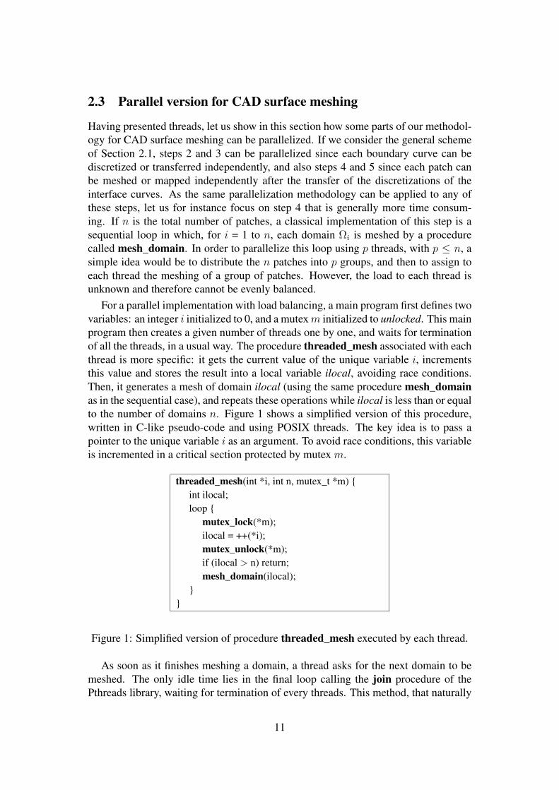
For a parallel implementation with load balancing, a main program first defines twovariables: an integer i initialized to 0, and a mutexm initialized to unlocked. This mainprogram then creates a given number of threads one by one, and waits for terminationof all the threads, in a usual way. The procedure threaded_mesh associated with eachthread is more specific: it gets the current value of the unique variable i, incrementsthis value and stores the result into a local variable ilocal, avoiding race conditions.Then, it generates a mesh of domain ilocal (using the same procedure mesh_domainas in the sequential case), and repeats these operations while ilocal is less than or equalto the number of domains n. Figure 1 shows a simplified version of this procedure,written in C-like pseudo-code and using POSIX threads. The key idea is to pass apointer to the unique variable i as an argument. To avoid race conditions, this variableis incremented in a critical section protected by mutex m.
threaded_mesh(int *i, int n, mutex_t *m) int ilocal;loop
mutex_lock(*m);ilocal = ++(*i);mutex_unlock(*m);if (ilocal > n) return;mesh_domain(ilocal);
Figure 1: Simplified version of procedure threaded_mesh executed by each thread.
As soon as it finishes meshing a domain, a thread asks for the next domain to bemeshed. The only idle time lies in the final loop calling the join procedure of thePthreads library, waiting for termination of every threads. This method, that naturally
11
ensures load balancing, has been improved by sorting the domains from the longestmeshing time to the shortest. This meshing time is simply estimated by consideringthe number of edges of the discretized boundary. In this way, assuming that the num-ber of patches n is sufficiently greater than the number of threads p, each processorhas nearly the same computation time.
When procedure mesh_domain is called in this parallel context, it is executed bymultiple threads at the same time, which requires thread safety. In our case, thisproperty is ensured by local storage. Indeed, the procedure does not use any globalvariable but only local variables, local pointers to dynamically allocated memory, anda general structure called blw and passed as an argument (that does not appear inthe simplified version of Figure 1 for a better readability). This structure contains inparticular the output mesh that is dynamically generated, and thus each thread has itsown copy of blw.
The above method can only be effective if CAD queries are fully parallelized,which is generally not the case because static caches are used. To address this is-sue, two different approaches are proposed below: the Pirate model with a continuoussurface representation, and the Discrete model using a discrete geometric support.
3 The Pirate model
In this section, a presentation of the Pirate model is followed by some performancemeasurements.
3.1 Description of the Pirate model
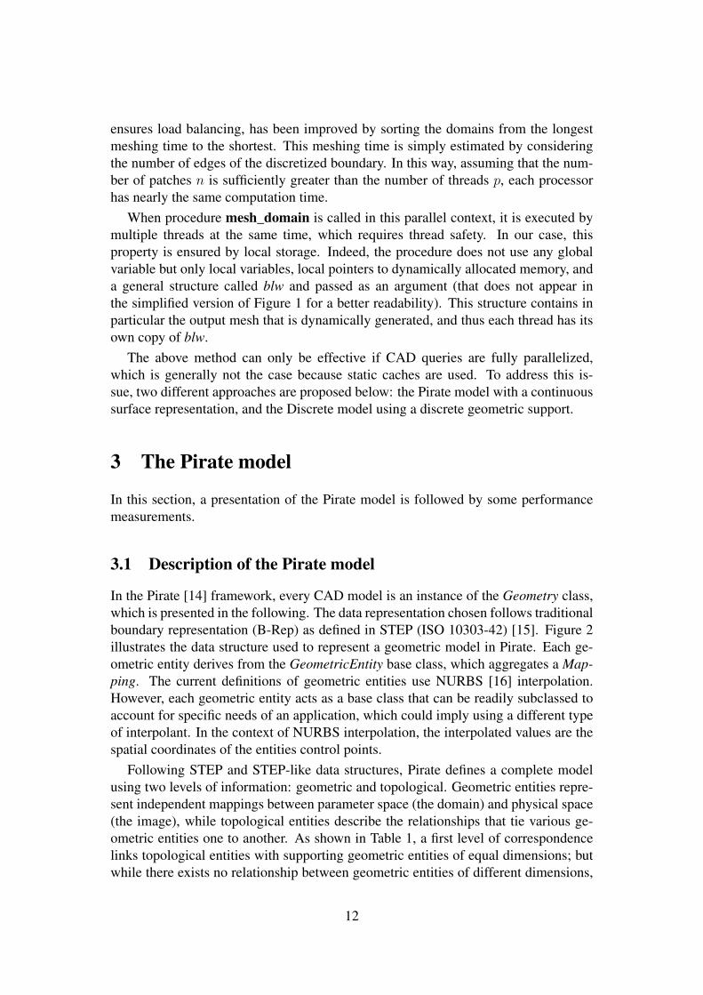
In the Pirate [14] framework, every CAD model is an instance of the Geometry class,which is presented in the following. The data representation chosen follows traditionalboundary representation (B-Rep) as defined in STEP (ISO 10303-42) [15]. Figure 2illustrates the data structure used to represent a geometric model in Pirate. Each ge-ometric entity derives from the GeometricEntity base class, which aggregates a Map-ping. The current definitions of geometric entities use NURBS [16] interpolation.However, each geometric entity acts as a base class that can be readily subclassed toaccount for specific needs of an application, which could imply using a different typeof interpolant. In the context of NURBS interpolation, the interpolated values are thespatial coordinates of the entities control points.
Following STEP and STEP-like data structures, Pirate defines a complete modelusing two levels of information: geometric and topological. Geometric entities repre-sent independent mappings between parameter space (the domain) and physical space(the image), while topological entities describe the relationships that tie various ge-ometric entities one to another. As shown in Table 1, a first level of correspondencelinks topological entities with supporting geometric entities of equal dimensions; butwhile there exists no relationship between geometric entities of different dimensions,
12
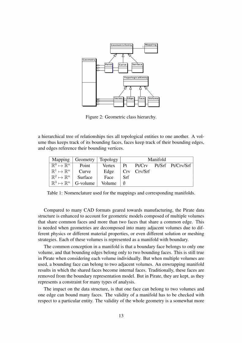
Figure 2: Geometric class hierarchy.
a hierarchical tree of relationships ties all topological entities to one another. A vol-ume thus keeps track of its bounding faces, faces keep track of their bounding edges,and edges reference their bounding vertices.
Mapping Geometry Topology ManifoldR0 7→ Rn Point Vertex Pt Pt/Crv Pt/Srf Pt/Crv/SrfR1 7→ Rn Curve Edge Crv Crv/SrfR2 7→ Rn Surface Face SrfR3 7→ Rn G-volume Volume ∅
Table 1: Nomenclature used for the mappings and corresponding manifolds.
Compared to many CAD formats geared towards manufacturing, the Pirate datastructure is enhanced to account for geometric models composed of multiple volumesthat share common faces and more than two faces that share a common edge. Thisis needed when geometries are decomposed into many adjacent volumes due to dif-ferent physics or different material properties, or even different solution or meshingstrategies. Each of these volumes is represented as a manifold with boundary.
The common conception in a manifold is that a boundary face belongs to only onevolume, and that bounding edges belong only to two bounding faces. This is still truein Pirate when considering each volume individually. But when multiple volumes areused, a bounding face can belong to two adjacent volumes. An enwrapping manifoldresults in which the shared faces become internal faces. Traditionally, these faces areremoved from the boundary representation model. But in Pirate, they are kept, as theyrepresents a constraint for many types of analysis.
The impact on the data structure, is that one face can belong to two volumes andone edge can bound many faces. The validity of a manifold has to be checked withrespect to a particular entity. The validity of the whole geometry is a somewhat more
13
complex operation than usual since it needs to take into account these internal faces,their bounding loops of edges and the vertices that bound these edges.
As Table 1 shows, all geometric entities in a model are mappings. As such, theyneed to be able to evaluate themselves. The first line of the table indicates that apoint can be evaluated directly or as a point on a curve (with one parameter t), or asa point on a surface (with two parameters u, v), or as a point on a curve belonging toa surface. The other lines of the table indicates evaluations for a curve or a surface.Furthermore, the NURBS representation of the geometric entities makes it possible toevaluate first and second order derivatives, which can be used for instance to solve theinverse mapping problem or to compute curvatures.
The only significant modification that was necessary to apply to the Pirate libraryinvolved eliminating the recourse to static caches used to speed up the evaluation ofB-Spline basis functions and there derivatives. In the original, sequential, version ofthe code, NURBS curve and surface classes each declared a number of class-scopedvectors that were allocated once and never destroyed. These vectors, used to evaluatebasis function values, were shared by all instances of their respective classes. Toprevent multiple simultaneous accesses to these vectors, the parallel version requireda modification where each instance of the curve and surface classes declares its owncopy of the vectors. However, while class-scoped variables may be changed even byconstant methods, which do not modify their object, this is not the case for objectattributes. The evaluation vectors therefore needed to be declared mutable so that theycould be used and changed through the execution of the evaluation methods, whichshould semantically not change their object.
3.2 Numerical results using the Pirate model
.The approach for parallel meshing of composite surfaces (cf. Section 2) is imple-
mented in the BLSURF [17] software. This software has been easily interfaced withthe Pirate library, since the geometrical and topological concepts of both environmentsare mutually compatible. Applications defined in Section 2.1, ωij : R → R2 andσi : R2 → R3, as well as their first and second order derivatives, are evaluated by theabove Pirate procedures associated with geometric entities. Topological informationis mainly provided by function get_id which, applied to any entity, returns an integercalled identity or reference. Two entities (e.g., curve segments) are topologically equalif and only if their references are equal.
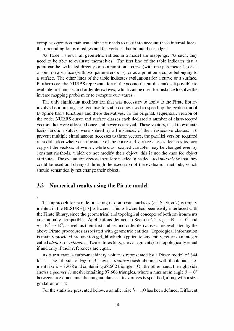
As a test case, a turbo-machinery volute is represented by a Pirate model of 844faces. The left side of Figure 3 shows a uniform mesh obtained with the default ele-ment size h = 7.938 and containing 28,502 triangles. On the other hand, the right sideshows a geometric mesh containing 97,606 triangles, where a maximum angle θ = 8
between an element and the tangent planes at its vertices is specified, along with a sizegradation of 1.2.
For the statistics presented below, a smaller size h = 1.0 has been defined. Different
14
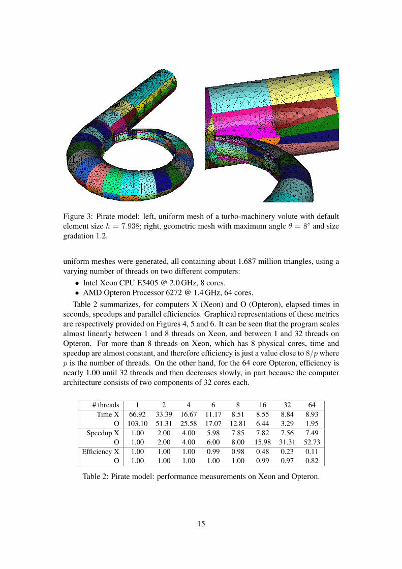
Figure 3: Pirate model: left, uniform mesh of a turbo-machinery volute with defaultelement size h = 7.938; right, geometric mesh with maximum angle θ = 8 and sizegradation 1.2.
uniform meshes were generated, all containing about 1.687 million triangles, using avarying number of threads on two different computers:• Intel Xeon CPU E5405 @ 2.0 GHz, 8 cores.• AMD Opteron Processor 6272 @ 1.4 GHz, 64 cores.
Table 2 summarizes, for computers X (Xeon) and O (Opteron), elapsed times inseconds, speedups and parallel efficiencies. Graphical representations of these metricsare respectively provided on Figures 4, 5 and 6. It can be seen that the program scalesalmost linearly between 1 and 8 threads on Xeon, and between 1 and 32 threads onOpteron. For more than 8 threads on Xeon, which has 8 physical cores, time andspeedup are almost constant, and therefore efficiency is just a value close to 8/pwherep is the number of threads. On the other hand, for the 64 core Opteron, efficiency isnearly 1.00 until 32 threads and then decreases slowly, in part because the computerarchitecture consists of two components of 32 cores each.
# threads 1 2 4 6 8 16 32 64Time X 66.92 33.39 16.67 11.17 8.51 8.55 8.84 8.93
O 103.10 51.31 25.58 17.07 12.81 6.44 3.29 1.95Speedup X 1.00 2.00 4.00 5.98 7.85 7.82 7.56 7.49
O 1.00 2.00 4.00 6.00 8.00 15.98 31.31 52.73Efficiency X 1.00 1.00 1.00 0.99 0.98 0.48 0.23 0.11
O 1.00 1.00 1.00 1.00 1.00 0.99 0.97 0.82
Table 2: Pirate model: performance measurements on Xeon and Opteron.
15
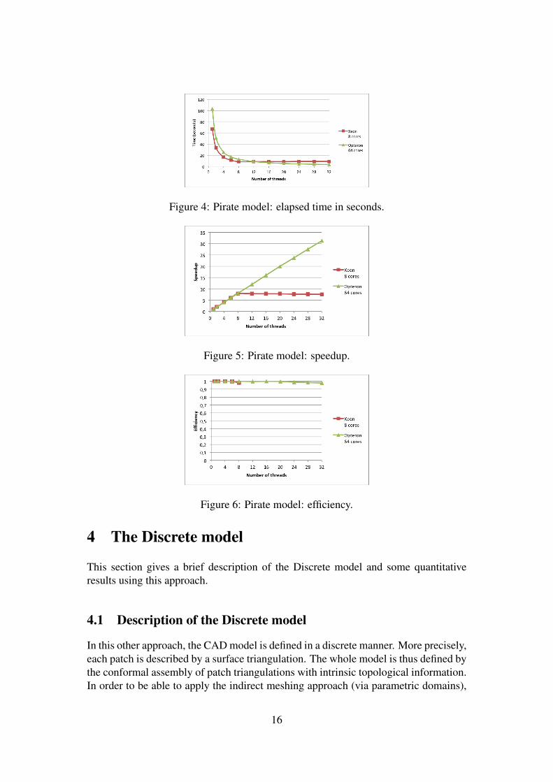
Figure 4: Pirate model: elapsed time in seconds.
Figure 5: Pirate model: speedup.
Figure 6: Pirate model: efficiency.
4 The Discrete model
This section gives a brief description of the Discrete model and some quantitativeresults using this approach.
4.1 Description of the Discrete model
In this other approach, the CAD model is defined in a discrete manner. More precisely,each patch is described by a surface triangulation. The whole model is thus defined bythe conformal assembly of patch triangulations with intrinsic topological information.In order to be able to apply the indirect meshing approach (via parametric domains),
16
we must construct for each patch a 2D parametric domain. These domains are gener-ated using a surface unfolding procedure. The latter is based on the minimization ofGreen-Lagrange tensor deformation between 3D and 2D elements. One can show thatthe above energy can be expressed by a quadratic function of coordinates and can belocally linearized. To solve this optimization problem, a simple iterative method basedon this local linearization is used. The resulting parametric domain has the advantageof being geometrically similar to the corresponding patch (the mapping of an elementof the parametric domain has almost the same shape on the patch, since the mappingis constructed so as to minimize the deformation).
For each patch, the resulting mapping is piecewise linear. Thus, the induced met-rics on parametric domains are piecewise constant. These metrics can be stored onlyonce before the meshing process. The CAD queries are replaced by first localizing apoint in a parametric domain (for a better efficiency, a “bucket grid” can be used), andthen retrieving the corresponding metric. All these computations can be made entirelyby evaluating functions that are internal to the mesher. As patches are mutually in-dependent and CAD queries are not needed anymore, patches are meshed in parallelwithout cache defaults inherent in the memory management of many CAD systems.
4.2 Numerical results using the Discrete model
To test this discrete approach, a program has been written to define parametric do-mains (unfolded patches) and also topological relations between patches. An inter-face has also been added to the BLSURF surface mesh generator [17] to read thisinformation and evaluate functions associated with the discrete model.
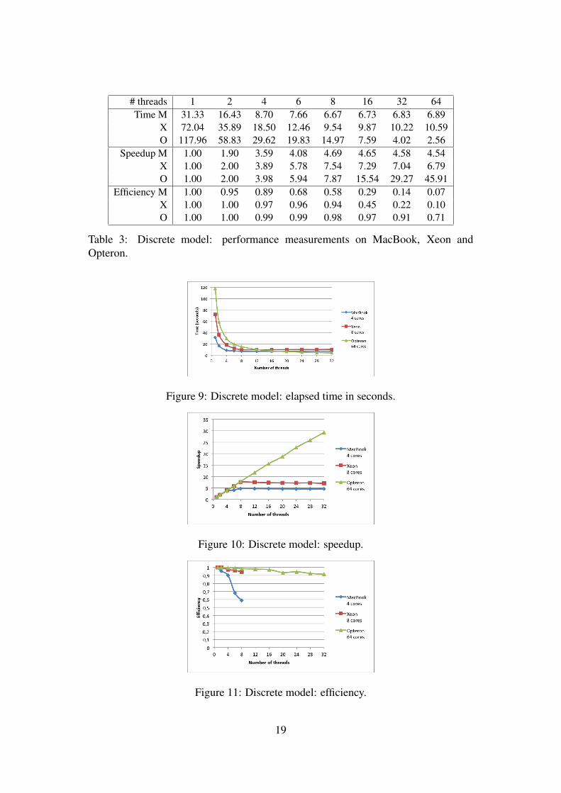
The test example is now a mechanical part made of 280 patches. Figure 7, on theleft side, shows the given 3D mesh of one of these patches. This mesh is unfolded,which results in the 2D mesh displayed on the right side. As previously, differentmeshes have been generated, and for instance Figure 8 shows a uniform mesh withelement size h = 0.02 (157,416 triangles) on the left, and h = 0.01 (625,836 triangles)on the right.
For performance evaluation, finer meshes have been generated, with a user-definedsize h = 0.006 (about 1.710 million triangles), using three computers:• Apple MacBook Pro, Intel Core i7 @ 2.0 GHz, 4 cores.• Intel Xeon CPU E5405 @ 2.0 GHz, 8 cores.• AMD Opteron Processor 6272 @ 1.4 GHz, 64 cores.
On the MacBook laptop, using the hyper-threading technique, the operating systemcan schedule two threads on a same physical core, making a total of 8 logical cores.The two other computers, Xeon and Opteron, are identical to those of Section 3.2.
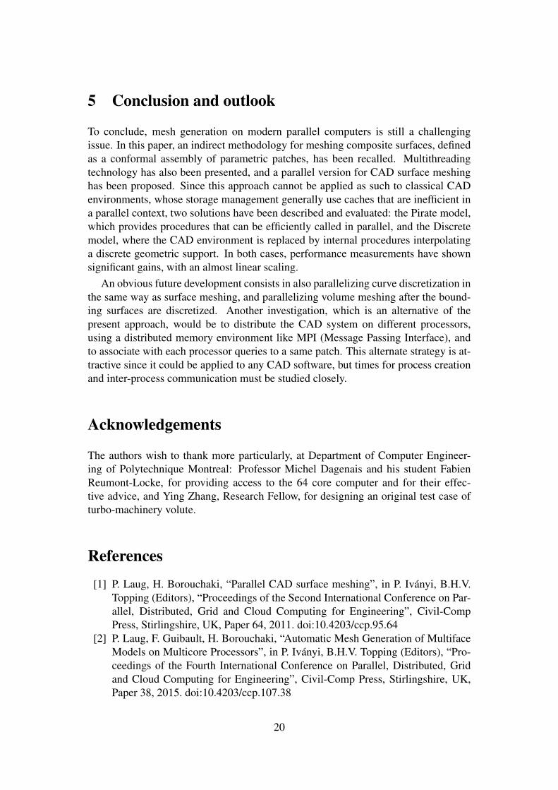
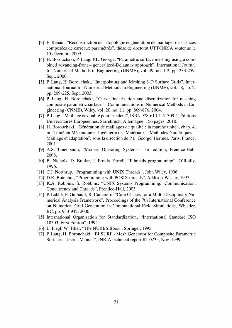
Table 3, as well as corresponding Figures 9, 10 and 11, show an almost linear scal-ing until 4 threads on MacBook, 8 threads on Xeon, and 32 threads on Opteron. Onthe 4 core MacBook, the elapsed time continues to decrease from 5 to 8 threads, butwith a lower efficiency, due to the hyper-threading technique. Then, it becomes almostconstant as expected On the 8 core Xeon and 64 core Opteron, the performance gains
17
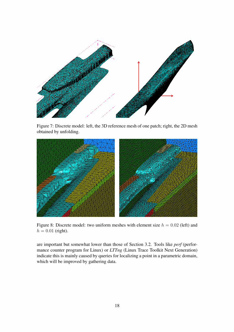
Figure 7: Discrete model: left, the 3D reference mesh of one patch; right, the 2D meshobtained by unfolding.
Figure 8: Discrete model: two uniform meshes with element size h = 0.02 (left) andh = 0.01 (right).
are important but somewhat lower than those of Section 3.2. Tools like perf (perfor-mance counter program for Linux) or LTTng (Linux Trace Toolkit Next Generation)indicate this is mainly caused by queries for localizing a point in a parametric domain,which will be improved by gathering data.
18
# threads 1 2 4 6 8 16 32 64Time M 31.33 16.43 8.70 7.66 6.67 6.73 6.83 6.89
X 72.04 35.89 18.50 12.46 9.54 9.87 10.22 10.59O 117.96 58.83 29.62 19.83 14.97 7.59 4.02 2.56
Speedup M 1.00 1.90 3.59 4.08 4.69 4.65 4.58 4.54X 1.00 2.00 3.89 5.78 7.54 7.29 7.04 6.79O 1.00 2.00 3.98 5.94 7.87 15.54 29.27 45.91
Efficiency M 1.00 0.95 0.89 0.68 0.58 0.29 0.14 0.07X 1.00 1.00 0.97 0.96 0.94 0.45 0.22 0.10O 1.00 1.00 0.99 0.99 0.98 0.97 0.91 0.71
Table 3: Discrete model: performance measurements on MacBook, Xeon andOpteron.
Figure 9: Discrete model: elapsed time in seconds.
Figure 10: Discrete model: speedup.
Figure 11: Discrete model: efficiency.
19
5 Conclusion and outlook
To conclude, mesh generation on modern parallel computers is still a challengingissue. In this paper, an indirect methodology for meshing composite surfaces, definedas a conformal assembly of parametric patches, has been recalled. Multithreadingtechnology has also been presented, and a parallel version for CAD surface meshinghas been proposed. Since this approach cannot be applied as such to classical CADenvironments, whose storage management generally use caches that are inefficient ina parallel context, two solutions have been described and evaluated: the Pirate model,which provides procedures that can be efficiently called in parallel, and the Discretemodel, where the CAD environment is replaced by internal procedures interpolatinga discrete geometric support. In both cases, performance measurements have shownsignificant gains, with an almost linear scaling.
An obvious future development consists in also parallelizing curve discretization inthe same way as surface meshing, and parallelizing volume meshing after the bound-ing surfaces are discretized. Another investigation, which is an alternative of thepresent approach, would be to distribute the CAD system on different processors,using a distributed memory environment like MPI (Message Passing Interface), andto associate with each processor queries to a same patch. This alternate strategy is at-tractive since it could be applied to any CAD software, but times for process creationand inter-process communication must be studied closely.
Acknowledgements
The authors wish to thank more particularly, at Department of Computer Engineer-ing of Polytechnique Montreal: Professor Michel Dagenais and his student FabienReumont-Locke, for providing access to the 64 core computer and for their effec-tive advice, and Ying Zhang, Research Fellow, for designing an original test case ofturbo-machinery volute.
References
[1] P. Laug, H. Borouchaki, “Parallel CAD surface meshing”, in P. Iványi, B.H.V.Topping (Editors), “Proceedings of the Second International Conference on Par-allel, Distributed, Grid and Cloud Computing for Engineering”, Civil-CompPress, Stirlingshire, UK, Paper 64, 2011. doi:10.4203/ccp.95.64
[2] P. Laug, F. Guibault, H. Borouchaki, “Automatic Mesh Generation of MultifaceModels on Multicore Processors”, in P. Iványi, B.H.V. Topping (Editors), “Pro-ceedings of the Fourth International Conference on Parallel, Distributed, Gridand Cloud Computing for Engineering”, Civil-Comp Press, Stirlingshire, UK,Paper 38, 2015. doi:10.4203/ccp.107.38
20
[3] E. Renaut, “Reconstruction de la topologie et génération de maillages de surfacescomposées de carreaux paramétrés”, thèse de doctorat UTT/INRIA soutenue le15 décembre 2009.
[4] H. Borouchaki, P. Laug, P.L. George, “Parametric surface meshing using a com-bined advancing-front – generalized-Delaunay approach”, International Journalfor Numerical Methods in Engineering (IJNME), vol. 49, no. 1-2, pp. 233-259,Sept. 2000.
[5] P. Laug, H. Borouchaki, “Interpolating and Meshing 3-D Surface Grids”, Inter-national Journal for Numerical Methods in Engineering (IJNME), vol. 58, no. 2,pp. 209-225, Sept. 2003.
[6] P. Laug, H. Borouchaki, “Curve linearization and discretization for meshingcomposite parametric surfaces”, Communications in Numerical Methods in En-gineering (CNME), Wiley, vol. 20, no. 11, pp. 869-876, 2004.
[7] P. Laug, “Maillage de qualité pour le calcul”, ISBN 978-613-1-51309-1, ÉditionsUniversitaires Européennes, Sarrebruck, Allemagne, 156 pages, 2010.
[8] H. Borouchaki, “Génération de maillages de qualité : la marche unité”, chap. 4,in “Traité en Mécanique et Ingénierie des Matériaux – Méthodes Numériques –Maillage et adaptation”, sous la direction de P.L. George, Hermès, Paris, France,2001.
[9] A.S. Tanenbaum, “Modern Operating Systems”, 3rd edition, Prentice-Hall,2008.
[10] B. Nichols, D. Buttlar, J. Proulx Farrell, “Pthreads programming”, O’Reilly,1996.
[11] C.J. Northrup, “Programming with UNIX Threads”, John Wiley, 1996.[12] D.R. Butenhof, “Programming with POSIX threads”, Addison-Wesley, 1997.[13] K.A. Robbins, S. Robbins, “UNIX Systems Programming: Communication,
Concurrency and Threads”, Prentice-Hall, 2003.[14] P. Labbé, F. Guibault, R. Camarero, “Core Classes for a Multi-Disciplinary Nu-
merical Analysis Framework”, Proceedings of the 7th International Conferenceon Numerical Grid Generation in Computational Field Simulations, Whistler,BC, pp. 933-942, 2000.
[15] International Organisation for Standardization, “International Standard ISO10303, First Edition”, 1994.
[16] L. Piegl, W. Tiller, “The NURBS Book”, Springer, 1995.[17] P. Laug, H. Borouchaki, “BLSURF - Mesh Generator for Composite Parametric
Surfaces - User’s Manual”, INRIA technical report RT-0235, Nov. 1999.
21