Embed Size (px)
Citation preview
Manual / Bedienungsanleitung / Mode d‘emploi
Diode SeriesDS-1000RGB | DS-2000RGB | DS-3000RGB
DS-1800G | DS-3000GDS-1600B | DS-5500B
Please spend a few minutes to read this manual fullybefore operating this laser!
Bitte lesen Sie diese Bedienungsanleitung sorgfältigvor Inbetriebnahme dieses Showlasersystems!
Avant d’utiliser cet appareil pour la première fois nous vous recommandonsde lire cette notice d’utilisation!
05/2019
EnglishDeutschFrançais
Manual: Diode Series
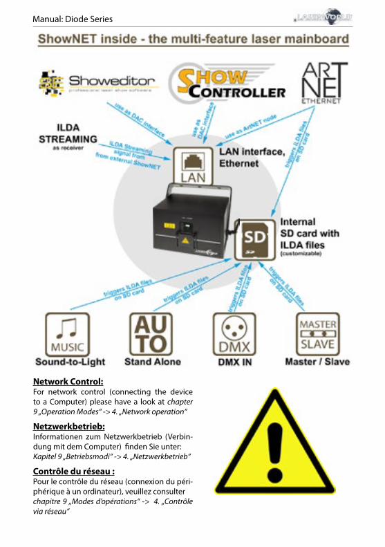
Network Control:For network control (connecting the device to a Computer) please have a look at chapter 9 „Operation Modes“ -> 4. „Network operation“
Netzwerkbetrieb:Informationen zum Netzwerkbetrieb (Verbin-dung mit dem Computer) finden Sie unter:Kapitel 9 „Betriebsmodi“ -> 4. „Netzwerkbetrieb“
Contrôle du réseau :Pour le contrôle du réseau (connexion du péri-phérique à un ordinateur), veuillez consulterchapitre 9 „Modes d’opérations“ -> 4. „Contrôle via réseau“

Manual: Diode Series
Rechtlicher Hinweis:
Die Firma Laserworld (Switzerland) AG behält sich das Recht vor, Änderungen an ih-ren Produkten vorzunehmen, die der technischen Weiterentwicklung dienen. Die-se Änderungen werden nicht notwendigerweise in jedem Einzelfall dokumentiert. Diese Betriebsanleitung und die darin enthaltenen Informationen wurden mit der gebotenen Sorgfalt zusammengestellt. Die Firma Laserworld (Switzerland) AG über-nimmt jedoch keine Gewähr für Druckfehler, andere Fehler oder daraus entstehende Schäden. Die in dieser Bedienungsanleitung genannten Marken und Produktnamen sind Warenzeichen oder eingetragene Warenzeichen der jeweiligen Titelhalter.
Legal notice:
Thank you for purchasing this Laserworld product. Due to continual product deve-lopments and technical improvements, Laserworld (Switzerland) AG reserves the right to make modifications to its products. This manual and its content have been made with due care but Laserworld (Switzerland) AG cannot however, take any res-ponsibility for any errors, omissions or any resulting damages forthwith. The brands and product names mentioned in this manual are trade marks or registered trade marks of their respective owners.
Information juridique :
L’entreprise Laserworld (Switzerland) AG se réserve le droit d’effectuer des modifica-tions concernant leurs produits et ainsi de répondre au développement technique. Ces modifications ne seront pas nécessairement annoncées en tout cas spécifique. Ce mode d’emploi et les informations contenues dedans ont été établis avec le soin minutieux qui s’impose dans ce cas. Laserworld (Switzerland) AG ne pourra pas être tenue responsable pour d’éventuelles erreurs d’impression ou dommages en résultants. En cas de doutes, veuillez toujours contacter Laserworld (Switzerland) AG . Les noms de marques et de produits utilisés dans ce mode d’emploi sont des marques de fab-rique ou des marques déposées.L’utilisation est réservée à un usage professionnel selon décret n°2007-665 du 2 mai 2007 relatif à la sécurité des appareils à laser sortant!
Article 4 bis : « Les usages spécifiques autorisés pour les appareils à laser sortant d’une classe su-périeure à 2 sont les usages professionnels suivants : (…)9° Spectacle et affichage : Toutes les applications de trajectoire, de visualisation, de projection ou de reproduc-tion d’images en deux ou trois dimensions. »
Manual: Diode Series
page 1 / 21
Content:
1. Product and package contents
2. Preliminary warning notices
3. Initial operations, safety instructions
4. Working on the device
5. Service notes
6. Warnings and other notices on the device
7. Device connections
8. General Operation
9. Operation Modes
10. FB4 version
Final statement
Technical data sheet
Laser specifications

Manual: Diode Series
page 2 / 21
1. Product and package contents
Please check if all listed parts are included and undamaged. Included in delivery:
1 x laser projector 2 x keys 1 x manual1 x power cable 1 x interlock bridge 1 x hex key
3. Initial operations, safety instructions
1. Make sure to use correct voltage; see in-formation on device & in this manual.
2. Make sure that the device is not connec-ted to mains during installation.
3. Installation has to be done by technical experienced and qualified persons ac-cording to safety regulations of the res-pective country.
4. Always ensure that maximum permis-sible exposure (MPE) is not exceeded in areas accessible to the public or members of staff.
5. In some countries an additional ins-pection by technical control institutes could be necessary.
6. Connect an easily accessible inter-lock connector or circuit breaker to the projector.
7. The power supply should be easily acces-sible.
8. When installing the laser mount it with a minimum distance of 15 cm from walls and objects.
9. For safe setup e.g. on walls or ceilings please use a safety cord. The safety cord should be able to withstand tenfold the weight of the device. Please follow the accident prevention regulations of pro-fessional associations and/or comparable regulations for accident prevention.
2. Preliminary warning notices
1. Please use this device only according to these operating instructions.
2. Do not use the device if there are any visible damages on housing, connector panels, power supplies or power cords.
3. This device must not be permanently connected to mains. Disconnect it from mains or use the power button to switch if off if not in use.
4. Never look directly into the light source of a laser projector. Danger of damage to the eyes or even blindness in extreme circumstances!
4. Do not operate the device at high humidity or in the rain or in dusty environments.
5. Protect device against dripping or splashing water. Do not place any liquid filled containers near to this device.
Any warranty claims are void if the warranty label is removed or tampered with in any way.
Manual: Diode Series
page 3 / 21
10. If the device has been exposed to great temperature changes, do not switch it on immediately. Condensation (or any moisture/water formed) may damage this device.
11. Never use dimmer, RC or other electroni-cally switched sockets. Whenever possib-le, do not use the laser projector together with large appliances (especially fog ma-chines) on the same mains!
12. Ensure sufficient ventilation and do not place the device on any warm or heat ra-diating surface. Especially the ventilati-on openings must not be covered!
13. Ensure that device does not get over-heated. Make sure that the device is not exposed to spotlights (especially moving heads). Heat of spotlights could overheat laser in a little while and leads to a degra-dation of performance.
14. This unit is intended for indoor use only.
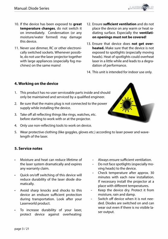
4. Working on the device
1. This product has no user serviceable parts inside and should only be maintained and serviced by a qualified engineer.
2. Be sure that the mains plug is not connected to the power supply while installing the device.
3. Take off all reflecting things like rings, watches, etc. before starting to work with or at the projector.
4. Only use non-reflecting tools to work on device.
5. Wear protective clothing (like goggles, gloves etc.) according to laser power and wave-length of the laser.
5. Service notes
• Moisture and heat can reduce lifetime of the laser system dramatically and expires any warranty claim.
• Quick on/off switching of this device will reduce durability of the laser diode dra-matically.
• Avoid sharp knocks and shocks to this device an endsure sufficient protection during transportation. Look after your Laserworld product.
• To increase durability of your laser, protect device against overheating:
- Always ensure sufficient ventilation. - Do not face spotlights (especially mo-
ving heads) to the device. - Check temperature after approx. 30
minutes with each new installation. If necessary install the projector at a place with different temperatures.
- Keep the device dry. Protect it from moisture, rain and damp.
- Switch off device when it is not nee-ded. Diodes are switched on and can wear out even if there is no visible la-ser output.
Manual: Diode Series
page 4 / 21
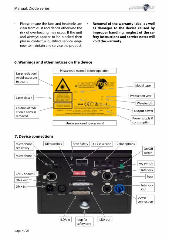
6. Warnings and other notices on the device
Laser radiation! Avoid exposure to beam.
Laser class 4
Caution of radi-ation if cover is removed
Power supply & consumption
Model type
Wavelength
Output power
Production year
Please read manual before operation
Use in enclosed spaces only!
• Please ensure the fans and heatsinks are clear from dust and debris otherwise the risk of overheating may occur. If the unit and airways appear to be blocked then please contact a qualified service engi-neer to maintain and service the product.
• Removal of the warranty label as well as damages to the device caused by improper handling, neglect of the sa-fety instructions and service notes will void the warranty.
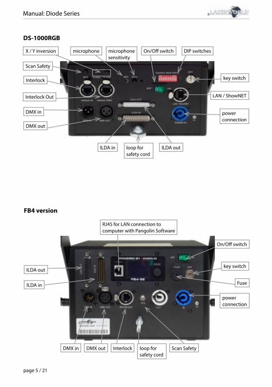
7. Device connections
DMX out
DIP switches
DMX in
ILDA in ILDA out
microphone
key switch
Interlock Out
loop for safety cord
On/Off switch
X / Y inversionScan Safetymicrophone sensitivity
Fuse
Color options
Interlock
power connection
LAN / ShowNET
Manual: Diode Series
page 5 / 21
FB4 version
DMX out
power connection
DMX in
ILDA in
ILDA outkey switch
loop for safety cord
On/Off switch
Fuse
Interlock Scan Safety
RJ45 for LAN connection to computer with Pangolin Software
DS-1000RGB
ILDA in ILDA outloop for safety cord
Interlock
Interlock Out
DMX in
DMX out
Scan Safety
microphone sensitivity
On/Off switch DIP switches
key switch
LAN / ShowNET
power connection
X / Y inversion microphone
Manual: Diode Series
page 6 / 21
8. General Operation
1. Power Connect the power cord to the device and to the mains. Make sure that your device is pro-vided with the correct voltage. Wrong voltage could lead to irreparable damages. Please find the correct voltage data in the synoptical table at the end of this manual. Make sure that the device is not directed to people or inflammable objects during installation. To start the device, connect the interlock bridge, insert the key and switch it on, and switch the device on. The “Emission - Laser on“ LED at the front side of the device begins to light up when the device is ready for use.
2. Key SwitchThere is a key switch at the back of the laser system. Please plug the key to the switch and turn it on. The laser device only runs when the key is inserted and switched on. Prevent misuse! Unplug the key when the laser is unattended to prevent misuse of the sys-tem.
3. Fuse There is a fuse at the back side of the device. If the fuse should blow, please exchange it with a new one. If the problems recurs, please contact your dealer or the Laserworld service department.
4. Safety PresetsThis device has an integrated Scan Safety (SFS). Is the Scan Safety active (on), single be-ams are prevented. If the Scan Safety is switched off, it is possible to create full power single beams - be careful!Operating the laser system with disabled SFS may not be allowed in some countries. Always ensure that maximum permissible exposure (MPE) is not exceeded in areas accessible to the public or members of staff.
5. X / Y InversionUse the X, Y, and/or X/Y buttons to invert the beams resp. patterns on the x-axis and/or y-axis.
6. Microphone SensitivitySet the microphone sensitivity by the ‚Sens‘ knob. This setting is needed for music mode / sound sensitive operation.
7. Colors (not available for DS-1000RGB)Use the ‚red‘, ‚green‘ and ‚blue‘ knobs to control the intensity per output color channel.
8. Modes / FunctionsThe different operation modes can be selected with using the DIP switches at the back of the device. Any change of the operation mode requires a restart of the device (switch the device off and on again or disconnect power and reconnect it again). Do not change any DIP switch settings during operation. Random and dangerous laser output can occur.
Manual: Diode Series
page 7 / 21
9. Turn device offTo turn off the device, use the power button („OFF“), turn the key to ‚OFF‘ and disconnect the power cable from the mains.
9. Operation Modes (Firmware version: 20190520x - Admin tool: v1.33)
This laser system can be operated in many different operation modes. It is possible to directly control the laser system via computer and laser show software as well as to trig-ger effects stored to the internal SD card via DMX/ArtNet consoles, in stand-alone mode or in sound-to-light mode. It is also possible to use the laser system as receiver for ILDA streaming signals from external ShowNET interfaces.
1. Download admin toolFor testing the show laser system and for other purposes, like uploading ILDA files to the integrated SD card, download the admin tool here: https://www.laserworld.com/shownet_mainboardOpen the „ShowNET-Admin_Tool.exe“ whenever this manual refers to the admin tool.IMPORTANT: It‘s not possible to access the admin tool, when you are accessing the laser system via software (Showeditor, Showcontroller, etc.). When opening the admin tool while accessing the laser system in a non-direct-control operation mode, the admin tool asks to press on a button to switch to network mode for manual control.
2. Direct computer controla) ILDA control with external DAC interface
The laser system can be controlled via ILDA control signal. There are an ILDA-in (ILDA input) and an ILDA-thropugh connector at the back side of the device. Connect the laser system to the control interface (DAC) by using an ILDA cable. Do not connect the laser to the standard parallel port at the computer, but always use an appropriate ILDA inter-face. After that the laser can becontrolled by a show laser control software. Use the ILDA-through connector to daisy-chain the ILDA signal to another laser system.
As this laser system has an integrated DAC interface as mainboard (ShowNET) it is pos-sible to directly control the laser via LAN without the need of ILDA cables or an external DAC interface.
b) Direct operation via laser show software, with LAN connection
(1) SHOWEDITOR - free laser show softwareThis laser system comes with an integrated network interface. The Showeditor laser soft-ware is included with this ShowNET mainboard for free. It is a full feature laser control software with LIVE and Timeline control mode and many free laser shows included in delivery. Use standard ethernet cable (RJ45 standard) to connect the LAN port of the show laser system to the computer. Standard network switches can be used to connect multiple laser systems at once.
Manual: Diode Series
page 8 / 21
The software can be downloaded for free on:https://www.showeditor.comAfter downloading and installing the software, open the .exe file on the computer and use the software to operate the show laser system.
Details on installation and use of the software please find on the aforementioned web-site.
(2) SHOWCONTROLLER - professional laser show and multimedia control software suiteThe integrated ShowNET mainboard fully supports the direct control of the laser via Showcontroller as well. Showcontroller is a mightly software tool with many professional features. It is very intuitive and thus easy to get started with, too.
The Software and a Demo Version can be downloaded on:https://www.showcontroller.comA license can be obtained from where this laser has been purchased.
3. Trigger ILDA files on the internal SD card and own effects This laser system has an integrated memory (SD card) that can hold ILDA files with laser frames and animations that can be triggered in different ways. It is possible to just use the standard files that come with delivery or change the files to new, custom ones.
a) Upload own ILDA files to the integrated SD cardBesides the possibility to just upload *.ild files to the SD card with a standard card reader, it is also possible to remotely load ILDA files to the integrated SD card via LAN without having to open the device and extract the SD card from the mainboard.
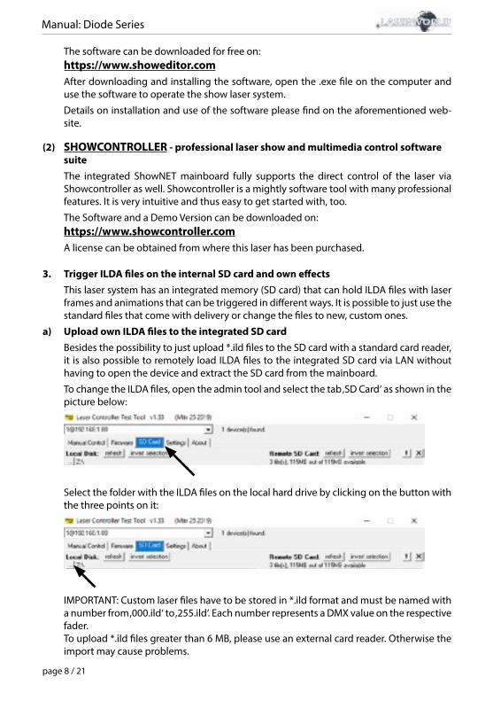
To change the ILDA files, open the admin tool and select the tab ‚SD Card‘ as shown in the picture below:
Select the folder with the ILDA files on the local hard drive by clicking on the button with the three points on it:
IMPORTANT: Custom laser files have to be stored in *.ild format and must be named with a number from ‚000.ild‘ to ‚255.ild‘. Each number represents a DMX value on the respective fader.To upload *.ild files greater than 6 MB, please use an external card reader. Otherwise the import may cause problems.
Manual: Diode Series
page 9 / 21
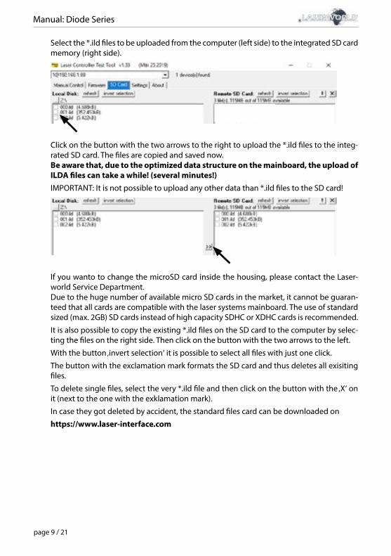
Select the *.ild files to be uploaded from the computer (left side) to the integrated SD card memory (right side).
Click on the button with the two arrows to the right to upload the *.ild files to the integ-rated SD card. The files are copied and saved now.Be aware that, due to the optimized data structure on the mainboard, the upload of ILDA files can take a while! (several minutes!)IMPORTANT: It is not possible to upload any other data than *.ild files to the SD card!
If you wanto to change the microSD card inside the housing, please contact the Laser-world Service Department.Due to the huge number of available micro SD cards in the market, it cannot be guaran-teed that all cards are compatible with the laser systems mainboard. The use of standard sized (max. 2GB) SD cards instead of high capacity SDHC or XDHC cards is recommended.
It is also possible to copy the existing *.ild files on the SD card to the computer by selec-ting the files on the right side. Then click on the button with the two arrows to the left.
With the button ‚invert selection‘ it is possible to select all files with just one click.
The button with the exclamation mark formats the SD card and thus deletes all exisiting files.
To delete single files, select the very *.ild file and then click on the button with the ‚X‘ on it (next to the one with the exklamation mark).
In case they got deleted by accident, the standard files card can be downloaded on
https://www.laser-interface.com
Manual: Diode Series
page 10 / 21
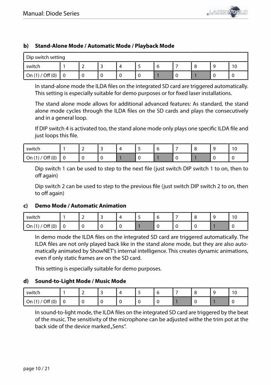
b) Stand-Alone Mode / Automatic Mode / Playback Mode
Dip switch setting
switch 1 2 3 4 5 6 7 8 9 10
On (1) / Off (0) 0 0 0 0 0 1 0 1 0 0
In stand-alone mode the ILDA files on the integrated SD card are triggered automatically. This setting is especially suitable for demo purposes or for fixed laser installations.
The stand alone mode allows for additional advanced features: As standard, the stand alone mode cycles through the ILDA files on the SD cards and plays the consecutively and in a general loop.
If DIP switch 4 is activated too, the stand alone mode only plays one specific ILDA file and just loops this file.
switch 1 2 3 4 5 6 7 8 9 10
On (1) / Off (0) 0 0 0 1 0 1 0 1 0 0
Dip switch 1 can be used to step to the next file (just switch DIP switch 1 to on, then to off again)
Dip switch 2 can be used to step to the previous file (just switch DIP switch 2 to on, then to off again)
c) Demo Mode / Automatic Animation
switch 1 2 3 4 5 6 7 8 9 10
On (1) / Off (0) 0 0 0 0 1 0 0 0 1 0
In demo mode the ILDA files on the integrated SD card are triggered automatically. The ILDA files are not only played back like in the stand alone mode, but they are also auto-matically animated by ShowNET‘s internal intelligence. This creates dynamic animations, even if only static frames are on the SD card.
This setting is especially suitable for demo purposes.
d) Sound-to-Light Mode / Music Mode
switch 1 2 3 4 5 6 7 8 9 10
On (1) / Off (0) 0 0 0 0 0 0 1 0 1 0
In sound-to-light mode, the ILDA files on the integrated SD card are triggered by the beat of the music. The sensitivity of the microphone can be adjusted withe the trim pot at the back side of the device marked „Sens“.
Manual: Diode Series
page 11 / 21
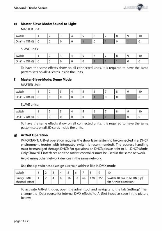
e) Master-Slave-Mode: Sound-to-LightMASTER unit:
switch 1 2 3 4 5 6 7 8 9 10
On (1) / Off (0) 0 0 0 0 1 0 1 0 1 0
SLAVE units:
switch 1 2 3 4 5 6 7 8 9 10
On (1) / Off (0) 0 0 0 0 0 1 1 1 0 0
To have the same effects show on all connected units, it is required to have the same pattern sets on all SD cards inside the units.
f) Master-Slave-Mode: Demo ModeMASTER Unit:
switch 1 2 3 4 5 6 7 8 9 10
On (1) / Off (0) 0 0 0 0 0 1 0 0 1 0
SLAVE units:
switch 1 2 3 4 5 6 7 8 9 10
On (1) / Off (0) 0 0 0 0 0 1 1 1 0 0
To have the same effects show on all connected units, it is required to have the same pattern sets on all SD cards inside the units.
g) ArtNet OperationIMPORTANT: ArtNet operation requires the show laser system to be connected in a DHCP environment (router with integrated switch is recommended). The address handling must be managed through DHCP. For questions on DHCP, please refer to 4.1. DHCP Mode.Only ShowNET interfaces and the ArtNet controller must be used in the same network.
Avoid using other network devices in the same network.
Use the dip switches to assign a certain address like in DMX mode:
switch 1 2 3 4 5 6 7 8 9 10
Binary DMX channel offset
1 2 4 8 16 32 64 128 256 Switch 10 has to be ON (up) for ArtNet operation
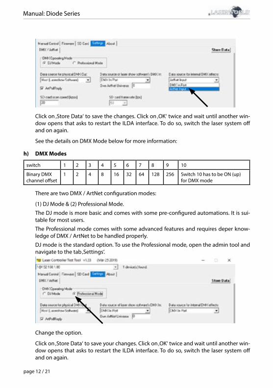
To activate ArtNet trigger, open the admin tool and navigate to the tab ‚Settings‘. Then change the ‚Data source for internal DMX effects‘ to ‚ArtNet input‘ as seen in the picture below:
Manual: Diode Series
page 12 / 21
Click on ‚Store Data‘ to save the changes. Click on ‚OK‘ twice and wait until another win-dow opens that asks to restart the ILDA interface. To do so, switch the laser system off and on again.
See the details on DMX Mode below for more information:
h) DMX Modes
switch 1 2 3 4 5 6 7 8 9 10
Binary DMX channel offset
1 2 4 8 16 32 64 128 256 Switch 10 has to be ON (up) for DMX mode
There are two DMX / ArtNet configuration modes:
(1) DJ Mode & (2) Professional Mode.
The DJ mode is more basic and comes with some pre-configured automations. It is sui-table for most users.
The Professional mode comes with some advanced features and requires deper know-ledge of DMX / ArtNet to be handled properly.
DJ mode is the standard option. To use the Professional mode, open the admin tool and navigate to the tab ‚Settings‘.
Change the option.
Click on ‚Store Data‘ to save your changes. Click on ‚OK‘ twice and wait until another win-dow opens that asks to restart the ILDA interface. To do so, switch the laser system off and on again.
Manual: Diode Series
page 13 / 21
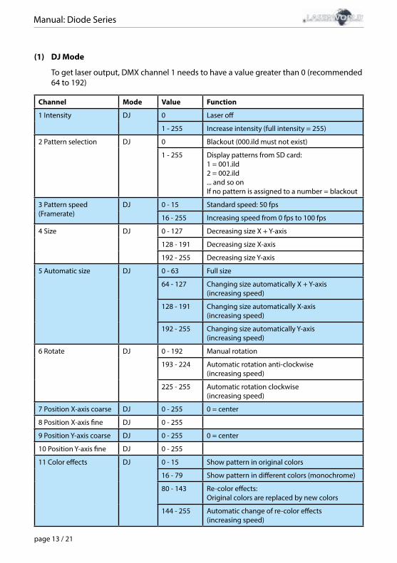
(1) DJ Mode
To get laser output, DMX channel 1 needs to have a value greater than 0 (recommended 64 to 192)
Channel Mode Value Function
1 Intensity DJ 0 Laser off
1 - 255 Increase intensity (full intensity = 255)
2 Pattern selection DJ 0 Blackout (000.ild must not exist)
1 - 255 Display patterns from SD card:1 = 001.ild2 = 002.ild ... and so onIf no pattern is assigned to a number = blackout
3 Pattern speed(Framerate)
DJ 0 - 15 Standard speed: 50 fps
16 - 255 Increasing speed from 0 fps to 100 fps
4 Size DJ 0 - 127 Decreasing size X + Y-axis
128 - 191 Decreasing size X-axis
192 - 255 Decreasing size Y-axis
5 Automatic size DJ 0 - 63 Full size
64 - 127 Changing size automatically X + Y-axis(increasing speed)
128 - 191 Changing size automatically X-axis(increasing speed)
192 - 255 Changing size automatically Y-axis(increasing speed)
6 Rotate DJ 0 - 192 Manual rotation
193 - 224 Automatic rotation anti-clockwise(increasing speed)
225 - 255 Automatic rotation clockwise(increasing speed)
7 Position X-axis coarse DJ 0 - 255 0 = center
8 Position X-axis fine DJ 0 - 255
9 Position Y-axis coarse DJ 0 - 255 0 = center
10 Position Y-axis fine DJ 0 - 255
11 Color effects DJ 0 - 15 Show pattern in original colors
16 - 79 Show pattern in different colors (monochrome)
80 - 143 Re-color effects: Original colors are replaced by new colors
144 - 255 Automatic change of re-color effects(increasing speed)
Manual: Diode Series
page 14 / 21
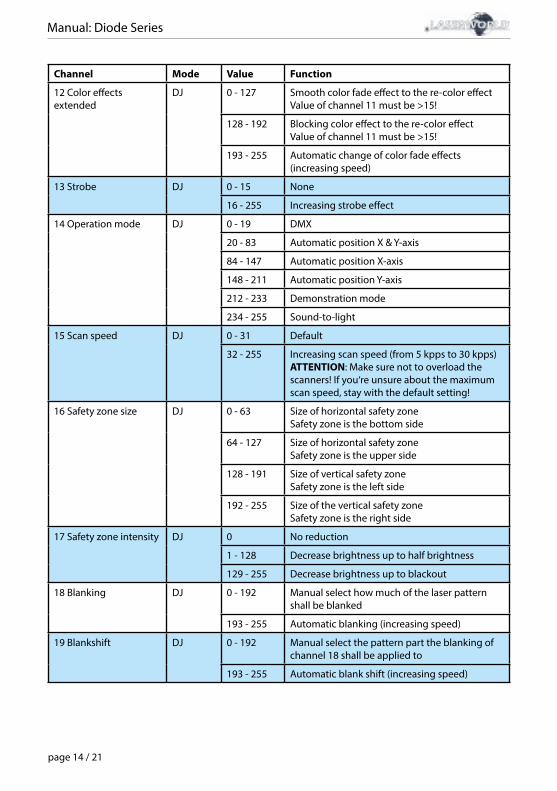
Channel Mode Value Function
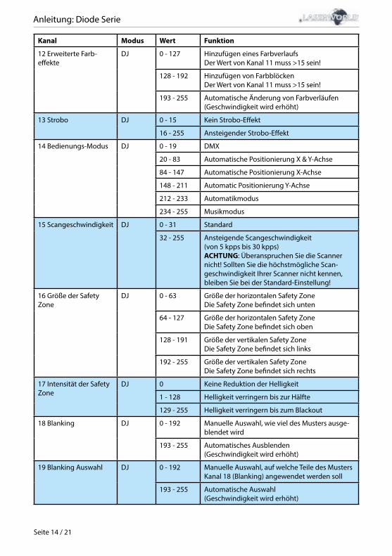
12 Color effectsextended
DJ 0 - 127 Smooth color fade effect to the re-color effectValue of channel 11 must be >15!
128 - 192 Blocking color effect to the re-color effectValue of channel 11 must be >15!
193 - 255 Automatic change of color fade effects(increasing speed)
13 Strobe DJ 0 - 15 None
16 - 255 Increasing strobe effect
14 Operation mode DJ 0 - 19 DMX
20 - 83 Automatic position X & Y-axis
84 - 147 Automatic position X-axis
148 - 211 Automatic position Y-axis
212 - 233 Demonstration mode
234 - 255 Sound-to-light
15 Scan speed DJ 0 - 31 Default
32 - 255 Increasing scan speed (from 5 kpps to 30 kpps)ATTENTION: Make sure not to overload the scanners! If you‘re unsure about the maximum scan speed, stay with the default setting!
16 Safety zone size DJ 0 - 63 Size of horizontal safety zoneSafety zone is the bottom side
64 - 127 Size of horizontal safety zoneSafety zone is the upper side
128 - 191 Size of vertical safety zoneSafety zone is the left side
192 - 255 Size of the vertical safety zoneSafety zone is the right side
17 Safety zone intensity DJ 0 No reduction
1 - 128 Decrease brightness up to half brightness
129 - 255 Decrease brightness up to blackout
18 Blanking DJ 0 - 192 Manual select how much of the laser pattern shall be blanked
193 - 255 Automatic blanking (increasing speed)
19 Blankshift DJ 0 - 192 Manual select the pattern part the blanking of channel 18 shall be applied to
193 - 255 Automatic blank shift (increasing speed)
Manual: Diode Series
page 15 / 21
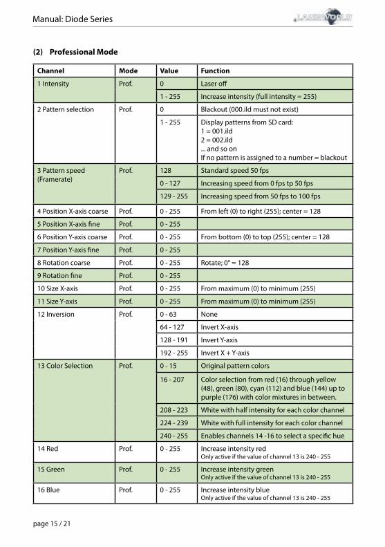
(2) Professional Mode
Channel Mode Value Function
1 Intensity Prof. 0 Laser off
1 - 255 Increase intensity (full intensity = 255)
2 Pattern selection Prof. 0 Blackout (000.ild must not exist)
1 - 255 Display patterns from SD card:1 = 001.ild2 = 002.ild ... and so onIf no pattern is assigned to a number = blackout
3 Pattern speed(Framerate)
Prof. 128 Standard speed 50 fps
0 - 127 Increasing speed from 0 fps tp 50 fps
129 - 255 Increasing speed from 50 fps to 100 fps
4 Position X-axis coarse Prof. 0 - 255 From left (0) to right (255); center = 128
5 Position X-axis fine Prof. 0 - 255
6 Position Y-axis coarse Prof. 0 - 255 From bottom (0) to top (255); center = 128
7 Position Y-axis fine Prof. 0 - 255
8 Rotation coarse Prof. 0 - 255 Rotate; 0° = 128
9 Rotation fine Prof. 0 - 255
10 Size X-axis Prof. 0 - 255 From maximum (0) to minimum (255)
11 Size Y-axis Prof. 0 - 255 From maximum (0) to minimum (255)
12 Inversion Prof. 0 - 63 None
64 - 127 Invert X-axis
128 - 191 Invert Y-axis
192 - 255 Invert X + Y-axis
13 Color Selection Prof. 0 - 15 Original pattern colors
16 - 207 Color selection from red (16) through yellow (48), green (80), cyan (112) and blue (144) up to purple (176) with color mixtures in between.
208 - 223 White with half intensity for each color channel
224 - 239 White with full intensity for each color channel
240 - 255 Enables channels 14 -16 to select a specific hue
14 Red Prof. 0 - 255 Increase intensity redOnly active if the value of channel 13 is 240 - 255
15 Green Prof. 0 - 255 Increase intensity greenOnly active if the value of channel 13 is 240 - 255
16 Blue Prof. 0 - 255 Increase intensity blueOnly active if the value of channel 13 is 240 - 255
Manual: Diode Series
page 16 / 21
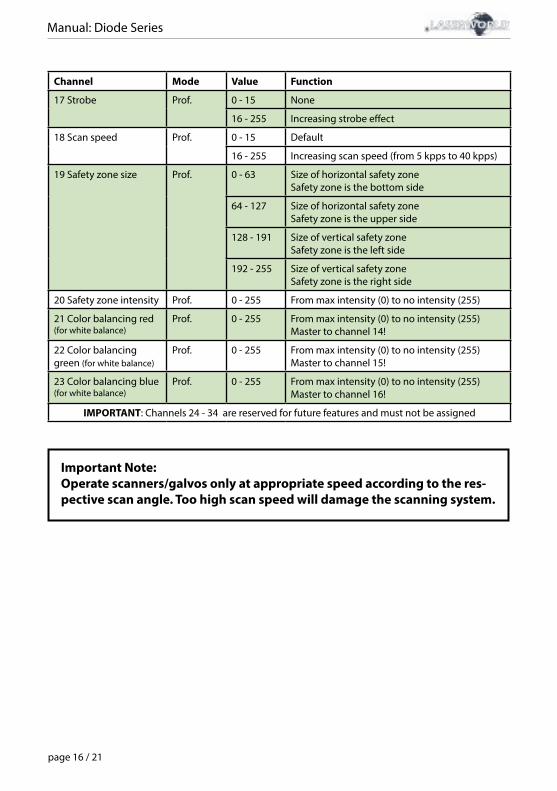
Channel Mode Value Function
17 Strobe Prof. 0 - 15 None
16 - 255 Increasing strobe effect
18 Scan speed Prof. 0 - 15 Default
16 - 255 Increasing scan speed (from 5 kpps to 40 kpps)
19 Safety zone size Prof. 0 - 63 Size of horizontal safety zoneSafety zone is the bottom side
64 - 127 Size of horizontal safety zoneSafety zone is the upper side
128 - 191 Size of vertical safety zoneSafety zone is the left side
192 - 255 Size of vertical safety zoneSafety zone is the right side
20 Safety zone intensity Prof. 0 - 255 From max intensity (0) to no intensity (255)
21 Color balancing red(for white balance)
Prof. 0 - 255 From max intensity (0) to no intensity (255)Master to channel 14!
22 Color balancing green (for white balance)
Prof. 0 - 255 From max intensity (0) to no intensity (255)Master to channel 15!
23 Color balancing blue(for white balance)
Prof. 0 - 255 From max intensity (0) to no intensity (255)Master to channel 16!
IMPORTANT: Channels 24 - 34 are reserved for future features and must not be assigned
Important Note:Operate scanners/galvos only at appropriate speed according to the res-pective scan angle. Too high scan speed will damage the scanning system.
Manual: Diode Series
page 17 / 21
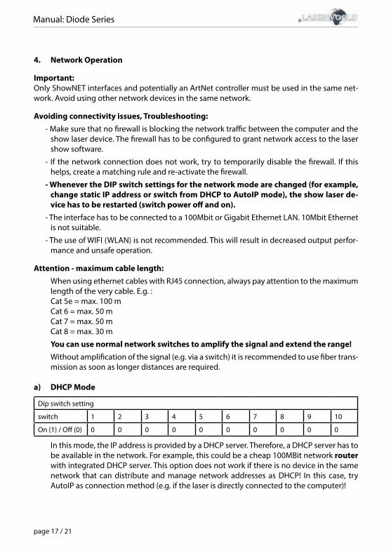
4. Network Operation
Important:Only ShowNET interfaces and potentially an ArtNet controller must be used in the same net-work. Avoid using other network devices in the same network.
Avoiding connectivity issues, Troubleshooting:- Make sure that no firewall is blocking the network traffic between the computer and the
show laser device. The firewall has to be configured to grant network access to the laser show software.
- If the network connection does not work, try to temporarily disable the firewall. If this helps, create a matching rule and re-activate the firewall.
- Whenever the DIP switch settings for the network mode are changed (for example, change static IP address or switch from DHCP to AutoIP mode), the show laser de-vice has to be restarted (switch power off and on).
- The interface has to be connected to a 100Mbit or Gigabit Ethernet LAN. 10Mbit Ethernet is not suitable.
- The use of WIFI (WLAN) is not recommended. This will result in decreased output perfor-mance and unsafe operation.
Attention - maximum cable length:When using ethernet cables with RJ45 connection, always pay attention to the maximum length of the very cable. E.g. :Cat 5e = max. 100 mCat 6 = max. 50 mCat 7 = max. 50 mCat 8 = max. 30 m
You can use normal network switches to amplify the signal and extend the range!Without amplification of the signal (e.g. via a switch) it is recommended to use fiber trans-mission as soon as longer distances are required.
a) DHCP Mode
Dip switch setting
switch 1 2 3 4 5 6 7 8 9 10
On (1) / Off (0) 0 0 0 0 0 0 0 0 0 0
In this mode, the IP address is provided by a DHCP server. Therefore, a DHCP server has to be available in the network. For example, this could be a cheap 100MBit network router with integrated DHCP server. This option does not work if there is no device in the same network that can distribute and manage network addresses as DHCP! In this case, try AutoIP as connection method (e.g. if the laser is directly connected to the computer)!
Manual: Diode Series
page 18 / 21
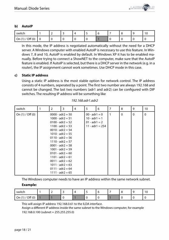
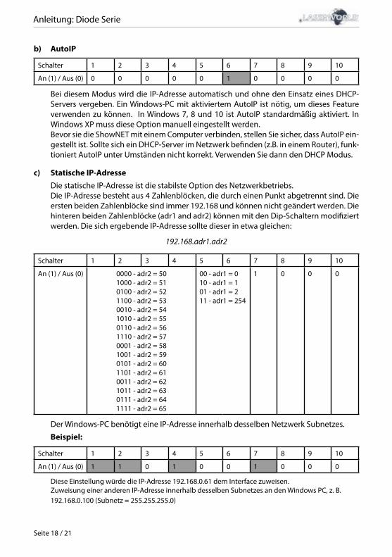
b) AutoIP
switch 1 2 3 4 5 6 7 8 9 10
On (1) / Off (0) 0 0 0 0 0 1 0 0 0 0
In this mode, the IP address is negotiated automatically without the need for a DHCP server. A Windows computer with enabled AutoIP is necessary to use this feature. In Win-dows 7, 8 and 10, AutoIP is enabled by default. In Windows XP it has to be enabled ma-nually. Before trying to connect a ShowNET to the computer, make sure that the AutoIP feature is enabled. If AutoIP is selected, but there is a DHCP server in the network (e.g. in a router), the IP assignment cannot work sometimes. Use DHCP mode in this case.
c) Static IP addressUsing a static IP address is the most stable option for network control. The IP address consists of 4 numbers, seperated by a point. The first two number are always 192.168 and cannot be changed. The last two numbers (adr1 and adr2) can be configured with DIP switches. The resulting IP address will be something like
192.168.adr1.adr2
switch 1 2 3 4 5 6 7 8 9 10
On (1) / Off (0) 0000 - adr2 = 501000 - adr2 = 510100 - adr2 = 521100 - adr2 = 530010 - adr2 = 541010 - adr2 = 550110 - adr2 = 561110 - adr2 = 570001 - adr2 = 581001 - adr2 = 590101 - adr2 = 601101 - adr2 = 610011 - adr2 = 621011 - adr2 = 630111 - adr2 = 641111 - adr2 = 65
00 - adr1 = 010 - adr1 = 101 - adr1 = 211 - adr1 = 254
1 0 0 0
The Windows computer needs to have an IP address within the same network subnet.
Example:
switch 1 2 3 4 5 6 7 8 9 10
On (1) / Off (0) 1 1 0 1 0 0 1 0 0 0
This will assign IP address 192.168.0.61 to the ILDA interface.Assign a different IP address inside the same subnet to the Windows computer, for example192.168.0.100 (subnet = 255.255.255.0)
Manual: Diode Series
page 19 / 21
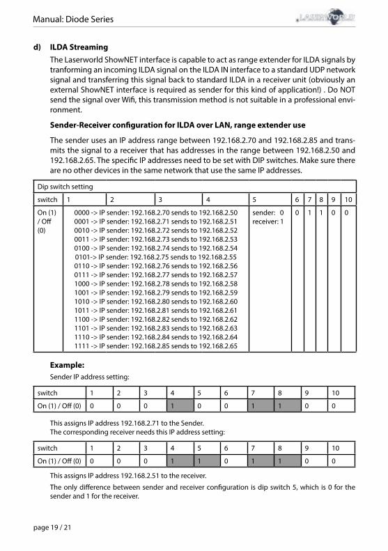
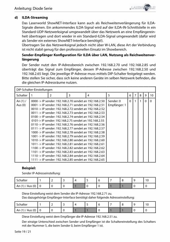
d) ILDA StreamingThe Laserworld ShowNET interface is capable to act as range extender for ILDA signals by tranforming an incoming ILDA signal on the ILDA IN interface to a standard UDP network signal and transferring this signal back to standard ILDA in a receiver unit (obviously an external ShowNET interface is required as sender for this kind of application!) . Do NOT send the signal over Wifi, this transmission method is not suitable in a professional envi-ronment.
Sender-Receiver configuration for ILDA over LAN, range extender use
The sender uses an IP address range between 192.168.2.70 and 192.168.2.85 and trans-mits the signal to a receiver that has addresses in the range between 192.168.2.50 and 192.168.2.65. The specific IP addresses need to be set with DIP switches. Make sure there are no other devices in the same network that use the same IP addresses.
Dip switch setting
switch 1 2 3 4 5 6 7 8 9 10
On (1) / Off (0)
0000 -> IP sender: 192.168.2.70 sends to 192.168.2.500001 -> IP sender: 192.168.2.71 sends to 192.168.2.510010 -> IP sender: 192.168.2.72 sends to 192.168.2.520011 -> IP sender: 192.168.2.73 sends to 192.168.2.530100 -> IP sender: 192.168.2.74 sends to 192.168.2.540101-> IP sender: 192.168.2.75 sends to 192.168.2.550110 -> IP sender: 192.168.2.76 sends to 192.168.2.560111 -> IP sender: 192.168.2.77 sends to 192.168.2.571000 -> IP sender: 192.168.2.78 sends to 192.168.2.581001 -> IP sender: 192.168.2.79 sends to 192.168.2.591010 -> IP sender: 192.168.2.80 sends to 192.168.2.601011 -> IP sender: 192.168.2.81 sends to 192.168.2.611100 -> IP sender: 192.168.2.82 sends to 192.168.2.621101 -> IP sender: 192.168.2.83 sends to 192.168.2.631110 -> IP sender: 192.168.2.84 sends to 192.168.2.641111 -> IP sender: 192.168.2.85 sends to 192.168.2.65
sender: 0receiver: 1
0 1 1 0 0
Example: Sender IP address setting:
switch 1 2 3 4 5 6 7 8 9 10
On (1) / Off (0) 0 0 0 1 0 0 1 1 0 0
This assigns IP address 192.168.2.71 to the Sender. The corresponding receiver needs this IP address setting:
switch 1 2 3 4 5 6 7 8 9 10
On (1) / Off (0) 0 0 0 1 1 0 1 1 0 0
This assigns IP address 192.168.2.51 to the receiver.
The only difference between sender and receiver configuration is dip switch 5, which is 0 for the sender and 1 for the receiver.
Manual: Diode Series
page 20 / 21
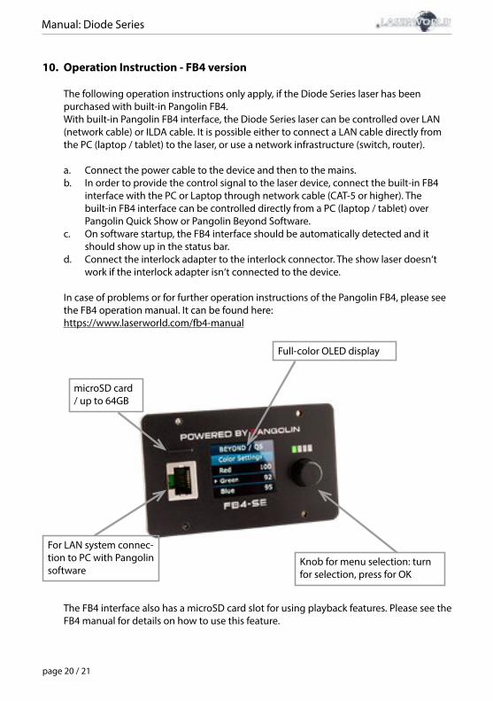
10. Operation Instruction - FB4 version
The following operation instructions only apply, if the Diode Series laser has been purchased with built-in Pangolin FB4.With built-in Pangolin FB4 interface, the Diode Series laser can be controlled over LAN (network cable) or ILDA cable. It is possible either to connect a LAN cable directly from the PC (laptop / tablet) to the laser, or use a network infrastructure (switch, router).
a. Connect the power cable to the device and then to the mains.b. In order to provide the control signal to the laser device, connect the built-in FB4 interface with the PC or Laptop through network cable (CAT-5 or higher). The built-in FB4 interface can be controlled directly from a PC (laptop / tablet) over Pangolin Quick Show or Pangolin Beyond Software. c. On software startup, the FB4 interface should be automatically detected and it should show up in the status bar.d. Connect the interlock adapter to the interlock connector. The show laser doesn‘t work if the interlock adapter isn‘t connected to the device.
In case of problems or for further operation instructions of the Pangolin FB4, please see the FB4 operation manual. It can be found here: https://www.laserworld.com/fb4-manual
microSD card / up to 64GB
For LAN system connec-tion to PC with Pangolin software
Full-color OLED display
Knob for menu selection: turn for selection, press for OK
The FB4 interface also has a microSD card slot for using playback features. Please see the FB4 manual for details on how to use this feature.

Manual: Diode Series
page 21 / 21
Final statement
Laserworld products are tested and product packaging is inspected before leaving ourwarehouse.Users must to follow the local safety regulations and warnings within this manual and adhereto any regulations within its place of use. Damages through inappropriate use will void anyliability or warranty of our products.Due to continual product developments, please check for the latest update of this productmanual at www.laserworld.com. If you do have any further questions, then please contactyour dealer/place of purchase or use our contact section on our website.For service issues, please contact your dealer/place of purchase and ensure only genuineLaserworld spare parts are used in any service repairs.
Errors and Omissions excepted and products are subject to change.
Laserworld (Switzerland) AG Kreuzlingerstrasse 58574 LengwilSwitzerland Registered office:8574 Lengwil / SwitzerlandCompany number: CH-440.3.020.548-6Commercial Registry Kanton ThurgauCEO: Martin WernerVAT no. (Switzerland): 683 180UID (Switzerland): CHE-113.954.889VAT no. (Germany): DE 258030001WEEE-Reg.-No. (Germany): DE 90759352
representative according to EMVG:Ray Technologies GmbHManaging Director: Martin WernerMühlbachweg 283626 Valley / Germany
Anleitung: Diode Serie
Seite 1 / 21
Inhaltverzeichnis:
1. Lieferumfang & Hinweise
2. Einleitende Warnhinweise
3. Schritte zur Inbetriebnahme, Sicherheitshinweise
4. Sicherheitshinweise für Arbeiten am Gerät
5. Pflege- und Wartungshinweise
6. Warnhinweise und Spezifikationen am Gerät
7. Geräteanschlüsse & Bedienelemente
8. Bedienung
9. Betriebsmodi
10. FB4-Version
Abschließende Erklärung
Technische Daten
Laserleistungsdaten

Anleitung: Diode Serie
Seite 2 / 21
1. Lieferumfang & Hinweise
Bitte prüfen Sie, ob Sie die Lieferung vollständig erhalten haben und die Ware unbeschädigt ist. Im Lieferumfang enthalten sind:
1 x Laserprojektor 2 x Schlüssel 1 x Bedienungsanleitung1 x Innensechskant-Schlüssel 1 x Interlock-Bridge 1 x Stromkabel
3. Schritte zur Inbetriebnahme, Sicherheitshinweise:
1. Stellen Sie sicher, dass Sie das Gerät mit der richtigen Spannung betreiben (siehe Angaben auf dem Gerät bzw. in dieser Bedienungsanleitung).
2. Stellen Sie sicher, dass das Gerät während der Installation nicht mit dem Strom-netz verbunden ist.
3. Der Laser darf nur von technisch versier-tem Fachpersonal gemäss der im jewei-ligen Land geltenden Sicherheitsbestim-mungen installiert werden.
4. Die am Betriebsort geforderten Sicher-heitsabstände zwischen Gerät und Publikum, bzw. maximal zulässige Be-strahlungswerte (MZB), müssen immer eingehalten werden.
5. In bestimmten Ländern kann zusätzlich
eine Abnahme durch ein technisches Überwachungsinstitut erforderlich sein.
6. Verbinden Sie einen leicht zugänglichen nterlock-Stecker bzw. Notausschalter mit dem Interlockanschluss.
7. Die Stromversorgung zugänglich halten.
8. Halten Sie bei der Installation einen Min-destabstand von 15 cm zur Wand und an-deren Objekten ein.
9. Bei einer Festinstallation an Wand, Decke o.ä., sichern Sie den Laser zusätzllich mit einem Sicherheitsfangseil. Das Fang-seil sollte mindestens dem 10-fachen Gewicht des Geräts standhalten können. Im Übrigen beachten Sie die Unfallverhü-tungsvorschriften der Berufsgenossen-schaften und/oder vergleichbare Rege-
2. Einleitende Warnhinweise
1. Betreiben Sie das Gerät nur gemäß dieser Bedienungsanleitung.
2. Benutzen Sie das Gerät nicht, wenn sichtbare Beschädigungen am Gehäuse, den An-schlussfeldern oder vor allem an den Stromversorgungsbuchsen oder -kabeln vorliegen.
3. Dieses Gerät darf nicht dauerhaft an das Stromnetz angeschlossen sein. Trennen Sie es von der Stromversorgung oder schalten Sie das Gerät mittels des Netzschalters aus, wenn Sie es nicht verwenden.
4. Niemals direkt in den Strahl des austretenden Lasers blicken. Dies könnte zu irreparab-len Schäden an den Augen und der Netzhaut führen. Erblindungsgefahr!
5. Gerät nicht bei hoher Luftfeuchtigkeit, Regen oder in staubiger Umgebung betrei-ben.
6. Vor Tropf-/Spritzwasser schützen, keine mit Flüssigkeit gefüllten Gefäße auf oder neben dem Gerät abstellen.
Bei Entfernung oder Manipulation des Garantielabels erlischt jeglicherAnspruch auf Gewährleistung!
Anleitung: Diode Serie
Seite 3 / 21
lungen zur Unfallverhütung
10. Wenn das Gerät großen Temperatur-schwankungen ausgesetzt war, schalten Sie es nicht unmittelbar danach an. Kon-denswasser (Nebel, Haze, usw.) kann zu Schäden am Gerät führen.
11. Benutzen Sie niemals Dimmer-, Funk- oder andere elektronisch gesteuerten Steckdosen! Falls möglich benutzen Sie den Laser nicht zusammen mit anderen großen elektrischen Verbrauchern (ins-besondere Nebelmaschinen) auf dersel-ben Leitung/Phase!
12. Sorgen Sie immer für eine ausreichende Belüftung und stellen Sie das Gerät auf keine warmen oder wärmeabstrahlen-den Untergründe. Die Belüftungsöffnun-gen dürfen nicht verdeckt sein.
13. Stellen Sie auch sicher, dass das Gerät nicht zu heiß wird und dass es nicht dem Strahl von Scheinwerfern ausgesetzt wird (insbesondere bei beweglichen Schein-werfern!). Die Wärme dieser Strahler kann den Laser überhitzen.
14. Dieses Gerät nur im Innenbereich ver-wenden
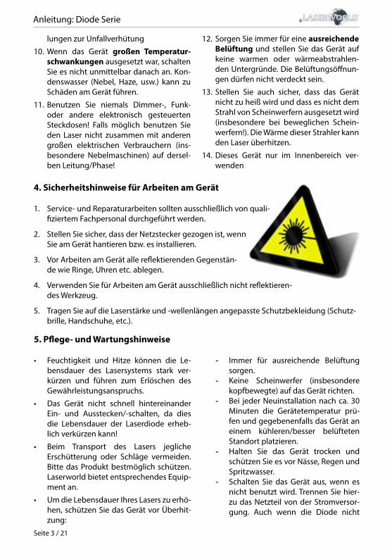
4. Sicherheitshinweise für Arbeiten am Gerät
1. Service- und Reparaturarbeiten sollten ausschließlich von quali-fiziertem Fachpersonal durchgeführt werden.
2. Stellen Sie sicher, dass der Netzstecker gezogen ist, wenn Sie am Gerät hantieren bzw. es installieren.
3. Vor Arbeiten am Gerät alle reflektierenden Gegenstän-de wie Ringe, Uhren etc. ablegen.
4. Verwenden Sie für Arbeiten am Gerät ausschließlich nicht reflektieren-des Werkzeug.
5. Tragen Sie auf die Laserstärke und -wellenlängen angepasste Schutzbekleidung (Schutz-brille, Handschuhe, etc.).
5. Pflege- und Wartungshinweise
• Feuchtigkeit und Hitze können die Le-bensdauer des Lasersystems stark ver-kürzen und führen zum Erlöschen des Gewährleistungsanspruchs.
• Das Gerät nicht schnell hintereinander Ein- und Ausstecken/-schalten, da dies die Lebensdauer der Laserdiode erheb-lich verkürzen kann!
• Beim Transport des Lasers jegliche Erschütterung oder Schläge vermeiden. Bitte das Produkt bestmöglich schützen. Laserworld bietet entsprechendes Equip-ment an.
• Um die Lebensdauer Ihres Lasers zu erhö-hen, schützen Sie das Gerät vor Überhit-zung:
- Immer für ausreichende Belüftung sorgen.
- Keine Scheinwerfer (insbesondere kopfbewegte) auf das Gerät richten.
- Bei jeder Neuinstallation nach ca. 30 Minuten die Gerätetemperatur prü-fen und gegebenenfalls das Gerät an einem kühleren/besser belüfteten Standort platzieren.
- Halten Sie das Gerät trocken und schützen Sie es vor Nässe, Regen und Spritzwasser.
- Schalten Sie das Gerät aus, wenn es nicht benutzt wird. Trennen Sie hier-zu das Netzteil von der Stromversor-gung. Auch wenn die Diode nicht
Anleitung: Diode Serie
Seite 4 / 21
leuchtet: Sie ist in Betrieb, solange das Gerät angeschaltet ist.
• Lüfter und Kühlkörper (Kühlrippen usw.) müssen frei von Staubansammlungen und Ablagerungen sein, da sonst die Ge-fahr des Überhitzens droht und jegliche Gewährleistung erlischt. Bitte wenden Sie sich an qualifizierte Fachpersonen.
• Durch das Entfernen des Garantiela-bels erlischt jeglicher Anspruch auf Gewährleistung. Schäden am Gerät, die durch unsachgemäßer Handha-bung, Nichtbeachtung der Sicher-heits-, Pflege- und Wartungshinweise entstehen besteht kein Gewährleis-tungsanspruch.
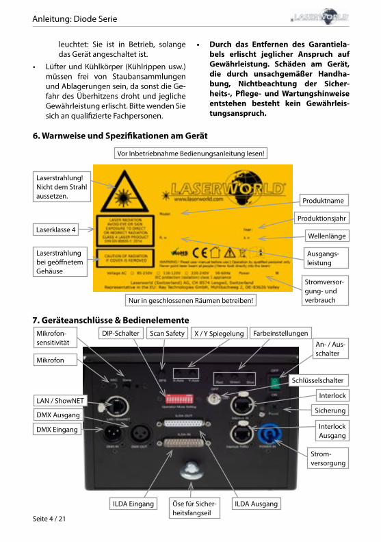
6. Warnweise und Spezifikationen am Gerät
Laserstrahlung!Nicht dem Strahl aussetzen.
Laserklasse 4
Laserstrahlung bei geöffnetem Gehäuse
Stromversor-gung- und verbrauch
Produktname
Wellenlänge
Ausgangs-leistung
Produktionsjahr
Vor Inbetriebnahme Bedienungsanleitung lesen!
Nur in geschlossenen Räumen betreiben!
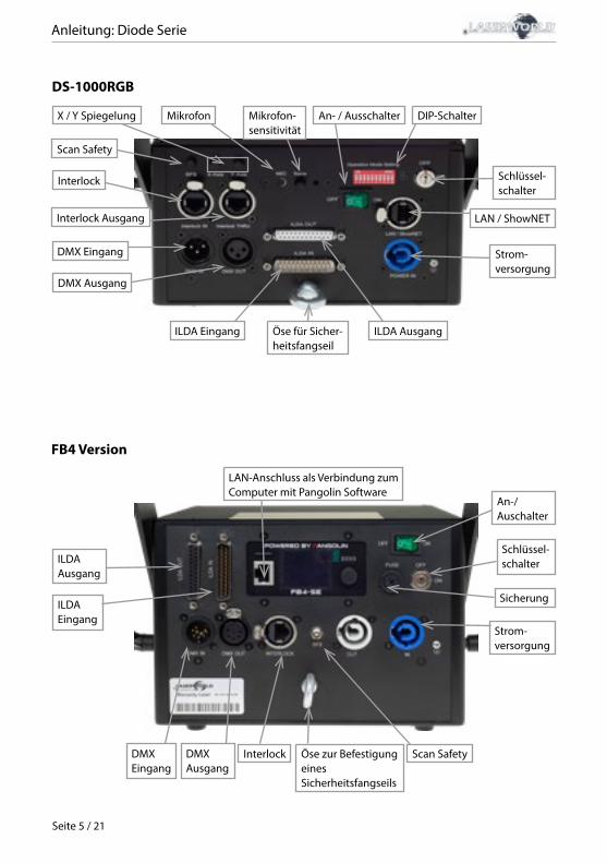
7. Geräteanschlüsse & Bedienelemente
DMX Ausgang
DIP-Schalter
DMX Eingang
ILDA Eingang ILDA Ausgang
Mikrofon
Schlüsselschalter
Interlock Ausgang
Öse für Sicher-heitsfangseil
An- / Aus-schalter
X / Y SpiegelungScan SafetyMikrofon-sensitivität
Sicherung
Farbeinstellungen
Interlock
Strom-versorgung
LAN / ShowNET
Anleitung: Diode Serie
Seite 5 / 21
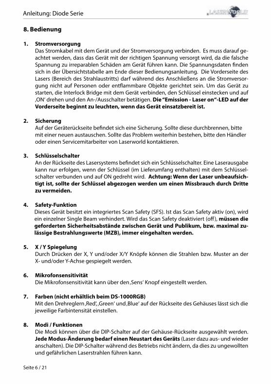
FB4 Version
DMXAusgang
Strom-versorgung
DMX Eingang
ILDA Eingang
ILDA Ausgang
Öse zur Befestigung eines Sicherheitsfangseils
Schlüssel-schalter
An-/Auschalter
Sicherung
Interlock Scan Safety
LAN-Anschluss als Verbindung zum Computer mit Pangolin Software
DS-1000RGB
ILDA Eingang ILDA AusgangÖse für Sicher-heitsfangseil
Interlock
Interlock Ausgang
DMX Eingang
DMX Ausgang
Scan Safety
Mikrofon-sensitivität
An- / Ausschalter DIP-Schalter
Schlüssel-schalter
LAN / ShowNET
Strom-versorgung
X / Y Spiegelung Mikrofon
Anleitung: Diode Serie
Seite 6 / 21
8. Bedienung
1. Stromversorgung Das Stromkabel mit dem Gerät und der Stromversorgung verbinden. Es muss darauf ge-achtet werden, dass das Gerät mit der richtigen Spannung versorgt wird, da die falsche Spannung zu irreparablen Schäden am Gerät führen kann. Die Spannungsdaten finden sich in der Übersichtstabelle am Ende dieser Bedienungsanleitung. Die Vorderseite des Lasers (Bereich des Strahlaustritts) darf während des Anschließens an die Stromversor-gung nicht auf Personen oder entflammbare Objekte gerichtet sein. Um das Gerät zu starten, die Interlock Bridge mit dem Gerät verbinden, den Schlüssel einstecken und auf ‚ON‘ drehen und den An-/Ausschalter betätigen. Die “Emission - Laser on“-LED auf der Vorderseite beginnt zu leuchten, wenn das Gerät einsatzbereit ist.
2. Sicherung Auf der Geräterückseite befindet sich eine Sicherung. Sollte diese durchbrennen, bitte mit einer neuen austauschen. Sollte das Problem weiterhin bestehen, bitte den Händler oder einen Servicemitarbeiter von Laserworld kontaktieren.
3. SchlüsselschalterAn der Rückseite des Lasersystems befindet sich ein Schlüsselschalter. Eine Laserausgabe kann nur erfolgen, wenn der Schlüssel (im Lieferumfang enthalten) mit dem Schlüssel-schalter verbunden und auf ON gedreht wird. Achtung: Wenn der Laser unbeaufsich-tigt ist, sollte der Schlüssel abgezogen werden um einen Missbrauch durch Dritte zu vermeiden.
4. Safety-FunktionDieses Gerät besitzt ein integriertes Scan Safety (SFS). Ist das Scan Safety aktiv (on), wird ein einzelner Single Beam verhindert. Wird das Scan Safety deaktiviert (off), müssen die geforderten Sicherheitsabstände zwischen Gerät und Publikum, bzw. maximal zu-lässige Bestrahlungswerte (MZB), immer eingehalten werden.
5. X / Y SpiegelungDurch Drücken der X, Y und/oder X/Y Knöpfe können die Strahlen bzw. Muster an der X- und/oder Y-Achse gespiegelt werden.
6. MikrofonsensitivitätDie Mikrofonsensitivität kann über den ‚Sens‘ Knopf eingestellt werden.
7. Farben (nicht erhältlich beim DS-1000RGB)Mit den Drehreglern ‚Red‘, ‚Green‘ und ‚Blue‘ auf der Rückseite des Gehäuses lässt sich die jeweilige Farbintensität einstellen.
8. Modi / FunktionenDie Modi können über die DIP-Schalter auf der Gehäuse-Rückseite ausgewählt werden. Jede Modus-Änderung bedarf einen Neustart des Geräts (Laser dazu aus- und wieder anschalten). Die DIP-Schalter während des Betriebs nicht ändern, da dies zu ungewollten und gefährlichen Laserstrahlen führen kann.
Anleitung: Diode Serie
Seite 7 / 21
9. Gerät ausschaltenUm das Gerät vollständig auszuschalten, „OFF“ am An- / Ausschalter drücken, den Schlüssel auf „OFF“ drehen und von der Stromversorgung trennen.
9. Betriebsmodi(Firmware: 20190520x - Admin tool: v1.33)
Dieses Lasersystem verfügt über viele verschiedene Betriebsarten: Es ist möglich, den Laser direkt mit dem Computer und einer Lasershow-Software zu steuern. Daneben können auf der internen SD-Karte gespeicherte Effekte mittels DMX-/ArtNet-Konsolen im Automatik- und Musikmodus ausgewählt und abgespielt werden. Es ist auch mög-lich, den Showlaser als Empfänger für ILDA-Streaming-Signale von externen ShowNET-Interfaces zu verwenden.
1. Admin-Tool herunterladenZum Testen des Lasersystems und für andere Zwecke, wie z.B. speichern von ILDA-Da-teien auf der integrierten SD-Karte, kann das Admin-Tool hier heruntergeladen werden:https://www.laserworld.com/shownet_mainboardÖffnen Sie „ShowNET-Admin_Tool.exe“, wenn diese Anleitung auf das Admin-Tool Bezug nimmt. WICHTIG: Es ist nicht möglich, mit dem Admin-Tool auf den Laser zuzugreifen, wenn gleichzeitig eine Lasersoftware auf den Showlaser zugreift (Showeditor, Showcontroller, etc.). Wenn Sie das Admin-Tool öffnen, während Sie auf das Lasersystem in einem nicht direkt gesteuerten Betriebsmodus zugreifen, fordert das Admin-Tool sie auf, eine Taste zu drücken, um in den Netzwerkmodus für manuelle Steuerung zu wechseln.
2. Direkte Ansteuerung mit dem Computera) ILDA-Ansteuerung mit externem DAC-Interface
Der Laser kann über das ILDA-Steuersignal gesteuert werden. Auf der Rückseite des Ge-räts befinden sich ein ILDA-in- (ILDA Eingang) und ein ILDA-through-Anschluss. Verbin-den Sie den Laser über ein ILDA-Kabel mit der Steuerschnittstelle (DAC). Schließen Sie den Laser nicht direkt an den Standard parallel Port ihres Computers, sondern verwenden Sie immer eine geeignetes ILDA-Interface. Danach kann der Showlaser mittels Lasersoft-ware angesteuert werden. Verwenden Sie den ILDA-through-Anschluss, um das ILDA-Signal an einen weiteren Laser durchzuschleifen (Daisy Chain).
Da dieses Lasersystem bereits über ein integriertes DAC-Interface auf dem Mainboard (ShowNET) verfügt, ist es auch möglich, den Laser direkt über LAN anzusteuern, ohne Verwendung eines ILDA-Kabels oder einem externen DAC-Interface.
b) Direkte Ansteuerung mit einer Lasersoftware per LAN-Verbindung
(1) SHOWEDITOR - kostenlose Lasersteuerungs-SoftwareDieses Lasersystem verfügt über ein integriertes Netzwerk-Interface. Die Software Show-editor ist kostenlos im Lieferumfang jeder ShowNET enthalten. Es handelt sich um eine komplette Lasersteuerungssoftware mit Live- und Timeline-Steuerungsmodi, die sehr viele kostenlose Lasershows beinhaltet.
Anleitung: Diode Serie
Seite 8 / 21
Verwenden Sie ein Ethernet-Kabel (RJ45-Standard), um den LAN-Anschluss des Show-lasers mit dem Computer zu verbinden. Mit Netzwerk-Switches können mehrere Laser gleichzeitig verbunden und angesteuert werden.
Die Software kann kostenlos hier heruntergelanden werden:https://www.showeditor.comNach dem Herunterladen und der Installation der Software öffnen Sie die dazugehörige .exe-Datei auf Ihrem Computer, um den Showlaser mit der Software zu steuern.
Details zur Installation und zur Bedienung der Software finden sie ebenfalls auf der zu-vorgenannten Webseite.
(2) SHOWCONTROLLER - professionelle Lasershow- und Multimedia-SoftwareDas integrierte ShowNET-Mainboard unterstützt auch die direkte Steuerung mit dem Showcontroller. Showcontroller ist ein mächtiges Software-Tool mit vielen professionel-len Funktionen. Diese sind intuitiv zu bedienen und damit auch für Einsteiger geeignet.
Die Software und eine Demo-Versionen können hier heruntergeladen werden:
https://www.showcontroller.comEine Software-Lizenz kann z.B. erworben werden, wo dieser Laser gekauft wurde.
3. ILDA-Dateien auf der internen SD-Karte und eigene Effekte abspielen Dieses Lasersystem verfügt über einen integrierten Speicher (SD-Karte), der Laserbilder und -animationen in Form von ILDA-Dateien speichern kann. Diese können auf verschie-dene Weise angesteuert werden. Es ist möglich, nur die im Lieferumfang enhtaltenen Standard-Effekte zu verwenden, oder diese mit selbst erstellten Dateien auszutauschen.
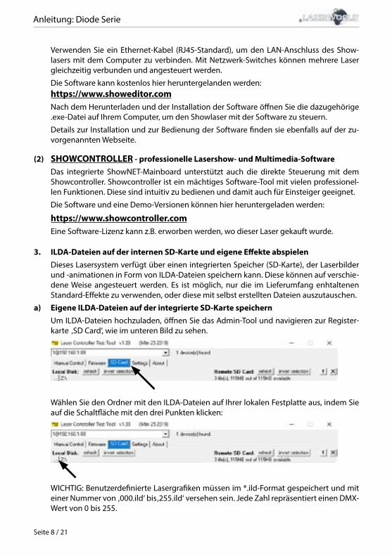
a) Eigene ILDA-Dateien auf der integrierte SD-Karte speichernUm ILDA-Dateien hochzuladen, öffnen Sie das Admin-Tool und navigieren zur Register-karte ‚SD Card‘, wie im unteren Bild zu sehen.
Wählen Sie den Ordner mit den ILDA-Dateien auf Ihrer lokalen Festplatte aus, indem Sie auf die Schaltfläche mit den drei Punkten klicken:
WICHTIG: Benutzerdefinierte Lasergrafiken müssen im *.ild-Format gespeichert und mit einer Nummer von ‚000.ild‘ bis ‚255.ild‘ versehen sein. Jede Zahl repräsentiert einen DMX-Wert von 0 bis 255.
Anleitung: Diode Serie
Seite 9 / 21
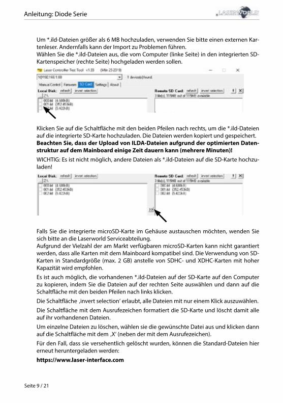
Um *.ild-Dateien größer als 6 MB hochzuladen, verwenden Sie bitte einen externen Kar-tenleser. Andernfalls kann der Import zu Problemen führen.Wählen Sie die *.ild-Dateien aus, die vom Computer (linke Seite) in den integrierten SD-Kartenspeicher (rechte Seite) hochgeladen werden sollen.
Klicken Sie auf die Schaltfläche mit den beiden Pfeilen nach rechts, um die *.ild-Dateien auf die integrierte SD-Karte hochzuladen. Die Dateien werden kopiert und gespeichert.Beachten Sie, dass der Upload von ILDA-Dateien aufgrund der optimierten Daten-struktur auf dem Mainboard einige Zeit dauern kann (mehrere Minuten)!WICHTIG: Es ist nicht möglich, andere Dateien als *.ild-Dateien auf die SD-Karte hochzu-laden!
Falls Sie die integrierte microSD-Karte im Gehäuse austauschen möchten, wenden Sie sich bitte an die Laserworld Serviceabteilung.Aufgrund der Vielzahl der am Markt verfügbaren microSD-Karten kann nicht garantiert werden, dass alle Karten mit dem Mainboard kompatibel sind. Die Verwendung von SD-Karten in Standardgröße (max. 2 GB) anstelle von SDHC- und XDHC-Karten mit hoher Kapazität wird empfohlen.
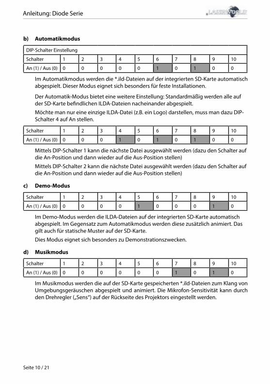
Es ist auch möglich, die vorhandenen *.ild-Dateien auf der SD-Karte auf den Computer zu kopieren, indem Sie die Dateien auf der rechten Seite auswählen und dann auf die Schaltfläche mit den beiden Pfeilen nach links klicken.
Die Schaltfläche ‚invert selection‘ erlaubt, alle Dateien mit nur einem Klick auszuwählen.
Die Schaltfläche mit dem Ausrufezeichen formatiert die SD-Karte und löscht damit alle auf ihr vorhandenen Dateien.
Um einzelne Dateien zu löschen, wählen sie die gewünschte Datei aus und klicken dann auf die Schaltfläche mit dem ‚X‘ (neben der mit dem Ausrufezeichen).
Für den Fall, dass sie versehentlich gelöscht wurden, können die Standard-Dateien hier erneut heruntergeladen werden:
https://www.laser-interface.com
Anleitung: Diode Serie
Seite 10 / 21
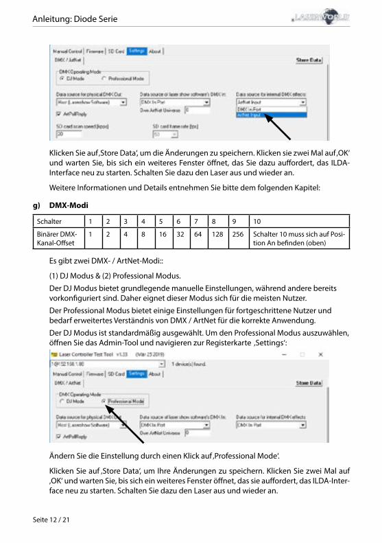
b) Automatikmodus
DIP-Schalter Einstellung
Schalter 1 2 3 4 5 6 7 8 9 10
An (1) / Aus (0) 0 0 0 0 0 1 0 1 0 0
Im Automatikmodus werden die *.ild-Dateien auf der integrierten SD-Karte automatisch abgespielt. Dieser Modus eignet sich besonders für feste Installationen.
Der Automatik-Modus bietet eine weitere Einstellung: Standardmäßig werden alle auf der SD-Karte befindlichen ILDA-Dateien nacheinander abgespielt.
Möchte man nur eine einzige ILDA-Datei (z.B. ein Logo) darstellen, muss man dazu DIP-Schalter 4 auf An stellen.
Schalter 1 2 3 4 5 6 7 8 9 10
An (1) / Aus (0) 0 0 0 1 0 1 0 1 0 0
Mittels DIP-Schalter 1 kann die nächste Datei ausgewählt werden (dazu den Schalter auf die An-Position und dann wieder auf die Aus-Position stellen)
Mittels DIP-Schalter 2 kann die nächste Datei ausgewählt werden (dazu den Schalter auf die An-Position und dann wieder auf die Aus-Position stellen)
c) Demo-Modus
Schalter 1 2 3 4 5 6 7 8 9 10
An (1) / Aus (0) 0 0 0 0 1 0 0 0 1 0
Im Demo-Modus werden die ILDA-Dateien auf der integrierten SD-Karte automatisch abgespielt. Im Gegensatz zum Automatikmodus werden diese zusätzlich animiert. Das gilt auch für statische Muster auf der SD-Karte.
Dies Modus eignet sich besonders zu Demonstrationszwecken.
d) Musikmodus
Schalter 1 2 3 4 5 6 7 8 9 10
An (1) / Aus (0) 0 0 0 0 0 0 1 0 1 0
Im Musikmodus werden die auf der SD-Karte gespeicherten *.ild-Dateien zum Klang von Umgebungsgeräuschen abgespielt und animiert. Die Mikrofon-Sensitivität kann durch den Drehregler („Sens“) auf der Rückseite des Projektors eingestellt werden.

Anleitung: Diode Serie
Seite 11 / 21
e) Master-Slave im MusikmodusMASTER-Projektor:
Schalter 1 2 3 4 5 6 7 8 9 10
An (1) / Aus (0) 0 0 0 0 1 0 1 0 1 0
SLAVE-Projektoren
Schalter 1 2 3 4 5 6 7 8 9 10
An (1) / Aus (0) 0 0 0 0 0 1 1 1 0 0
Damit auf allen Projektoren dieselben Effekte dargestellt werden, müssen auf allen in-tegrierten SD-Karten dieselben *.ild-Dateien in derselben Reihenfolge gespeichert sein.
f) Master-Slave im Demo-ModusMASTER-Projektor:
Schalter 1 2 3 4 5 6 7 8 9 10
An (1) / Aus (0) 0 0 0 0 0 1 0 0 1 0
SLAVE-Projektoren
Schalter 1 2 3 4 5 6 7 8 9 10
An (1) / Aus (0) 0 0 0 0 0 1 1 1 0
Damit auf allen Projektoren dieselben Effekte dargestellt werden, müssen auf allen in-tegrierten SD-Karten dieselben *.ild-Dateien in derselben Reihenfolge gespeichert sein.
g) Steuerung mit ArtNetWICHTIG: Um mit ArtNet angesteuert werden zu können, muss sich der Showlaser in einer DHCP-Umgebung befinden (Router mit integriertem Switch wird empfohlen). Die Vergabe der IP-Adresse muss über DHCP geschehen. Weitere Informationen zu DHCP fin-den Sie unter Punkt 4.1. DHCP Modus.Es dürfen sich nur ShowNET-Interfaces und der ArtNet-Controller im selben Netzwerk befinden.
Verwenden Sie die DIP-Schalter, um wie im DMX-Modus eine Adresse festzulegen:
Schalter 1 2 3 4 5 6 7 8 9 10
Binärer DMX-Kanal-Offset
1 2 4 8 16 32 64 128 256 Schalter 10 muss sich auf Posi-tion An befinden (oben)
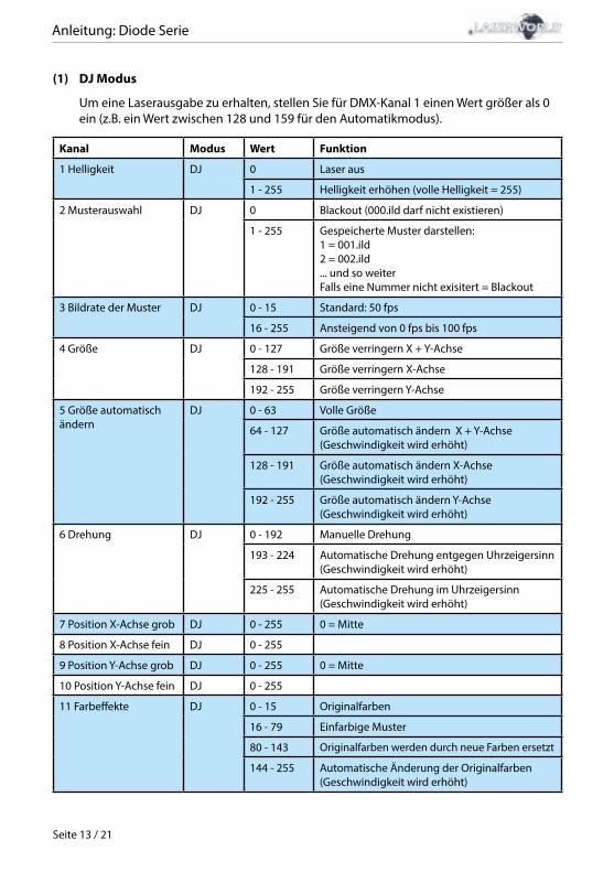
Um die ArtNet-Steuerung zu aktivieren, öffnen Sie das Admin-Tool und navigieren Sie zur Registerkarte ‚Settings‘. Ändern Sie die Auswahl ‚Data source for internal DMX effects‘ zu ‚ArtNet input‘, wie auf dem Bild unten zu sehen:
Anleitung: Diode Serie
Seite 12 / 21
Klicken Sie auf ‚Store Data‘, um die Änderungen zu speichern. Klicken sie zwei Mal auf ‚OK‘ und warten Sie, bis sich ein weiteres Fenster öffnet, das Sie dazu auffordert, das ILDA-Interface neu zu starten. Schalten Sie dazu den Laser aus und wieder an.
Weitere Informationen und Details entnehmen Sie bitte dem folgenden Kapitel:
g) DMX-Modi
Schalter 1 2 3 4 5 6 7 8 9 10
Binärer DMX-Kanal-Offset
1 2 4 8 16 32 64 128 256 Schalter 10 muss sich auf Posi-tion An befinden (oben)
Es gibt zwei DMX- / ArtNet-Modi::
(1) DJ Modus & (2) Professional Modus.
Der DJ Modus bietet grundlegende manuelle Einstellungen, während andere bereits vorkonfiguriert sind. Daher eignet dieser Modus sich für die meisten Nutzer.
Der Professional Modus bietet einige Einstellungen für fortgeschrittene Nutzer und bedarf erweitertes Verständnis von DMX / ArtNet für die korrekte Anwendung.
Der DJ Modus ist standardmäßig ausgewählt. Um den Professional Modus auszuwählen, öffnen Sie das Admin-Tool und navigieren zur Registerkarte ‚Settings‘:
Ändern Sie die Einstellung durch einen Klick auf ‚Professional Mode‘.
Klicken Sie auf ‚Store Data‘, um Ihre Änderungen zu speichern. Klicken Sie zwei Mal auf ‚OK‘ und warten Sie, bis sich ein weiteres Fenster öffnet, das sie auffordert, das ILDA-Inter-face neu zu starten. Schalten Sie dazu den Laser aus und wieder an.
Anleitung: Diode Serie
Seite 13 / 21
(1) DJ Modus
Um eine Laserausgabe zu erhalten, stellen Sie für DMX-Kanal 1 einen Wert größer als 0 ein (z.B. ein Wert zwischen 128 und 159 für den Automatikmodus).
Kanal Modus Wert Funktion
1 Helligkeit DJ 0 Laser aus
1 - 255 Helligkeit erhöhen (volle Helligkeit = 255)
2 Musterauswahl DJ 0 Blackout (000.ild darf nicht existieren)
1 - 255 Gespeicherte Muster darstellen:1 = 001.ild2 = 002.ild ... und so weiterFalls eine Nummer nicht exisitert = Blackout
3 Bildrate der Muster DJ 0 - 15 Standard: 50 fps
16 - 255 Ansteigend von 0 fps bis 100 fps
4 Größe DJ 0 - 127 Größe verringern X + Y-Achse
128 - 191 Größe verringern X-Achse
192 - 255 Größe verringern Y-Achse
5 Größe automatisch ändern
DJ 0 - 63 Volle Größe
64 - 127 Größe automatisch ändern X + Y-Achse(Geschwindigkeit wird erhöht)
128 - 191 Größe automatisch ändern X-Achse(Geschwindigkeit wird erhöht)
192 - 255 Größe automatisch ändern Y-Achse(Geschwindigkeit wird erhöht)
6 Drehung DJ 0 - 192 Manuelle Drehung
193 - 224 Automatische Drehung entgegen Uhrzeigersinn(Geschwindigkeit wird erhöht)
225 - 255 Automatische Drehung im Uhrzeigersinn(Geschwindigkeit wird erhöht)
7 Position X-Achse grob DJ 0 - 255 0 = Mitte
8 Position X-Achse fein DJ 0 - 255
9 Position Y-Achse grob DJ 0 - 255 0 = Mitte
10 Position Y-Achse fein DJ 0 - 255
11 Farbeffekte DJ 0 - 15 Originalfarben
16 - 79 Einfarbige Muster
80 - 143 Originalfarben werden durch neue Farben ersetzt
144 - 255 Automatische Änderung der Originalfarben(Geschwindigkeit wird erhöht)
Anleitung: Diode Serie
Seite 14 / 21
Kanal Modus Wert Funktion
12 Erweiterte Farb-effekte
DJ 0 - 127 Hinzufügen eines FarbverlaufsDer Wert von Kanal 11 muss >15 sein!
128 - 192 Hinzufügen von FarbblöckenDer Wert von Kanal 11 muss >15 sein!
193 - 255 Automatische Änderung von Farbverläufen(Geschwindigkeit wird erhöht)
13 Strobo DJ 0 - 15 Kein Strobo-Effekt
16 - 255 Ansteigender Strobo-Effekt
14 Bedienungs-Modus DJ 0 - 19 DMX
20 - 83 Automatische Positionierung X & Y-Achse
84 - 147 Automatische Positionierung X-Achse
148 - 211 Automatic Positionierung Y-Achse
212 - 233 Automatikmodus
234 - 255 Musikmodus
15 Scangeschwindigkeit DJ 0 - 31 Standard
32 - 255 Ansteigende Scangeschwindigkeit (von 5 kpps bis 30 kpps)ACHTUNG: Überanspruchen Sie die Scanner nicht! Sollten Sie die höchstmögliche Scan-geschwindigkeit Ihrer Scanner nicht kennen, bleiben Sie bei der Standard-Einstellung!
16 Größe der Safety Zone
DJ 0 - 63 Größe der horizontalen Safety ZoneDie Safety Zone befindet sich unten
64 - 127 Größe der horizontalen Safety ZoneDie Safety Zone befindet sich oben
128 - 191 Größe der vertikalen Safety ZoneDie Safety Zone befindet sich links
192 - 255 Größe der vertikalen Safety ZoneDie Safety Zone befindet sich rechts
17 Intensität der Safety Zone
DJ 0 Keine Reduktion der Helligkeit
1 - 128 Helligkeit verringern bis zur Hälfte
129 - 255 Helligkeit verringern bis zum Blackout
18 Blanking DJ 0 - 192 Manuelle Auswahl, wie viel des Musters ausge-blendet wird
193 - 255 Automatisches Ausblenden(Geschwindigkeit wird erhöht)
19 Blanking Auswahl DJ 0 - 192 Manuelle Auswahl, auf welche Teile des Musters Kanal 18 (Blanking) angewendet werden soll
193 - 255 Automatische Auswahl(Geschwindigkeit wird erhöht)
Anleitung: Diode Serie
Seite 15 / 21
(2) Professional Modus
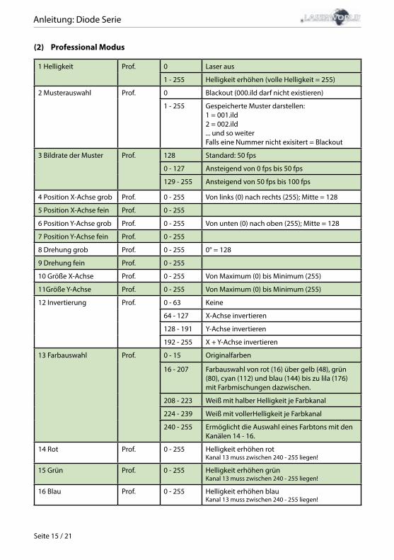
1 Helligkeit Prof. 0 Laser aus
1 - 255 Helligkeit erhöhen (volle Helligkeit = 255)
2 Musterauswahl Prof. 0 Blackout (000.ild darf nicht existieren)
1 - 255 Gespeicherte Muster darstellen:1 = 001.ild2 = 002.ild ... und so weiterFalls eine Nummer nicht exisitert = Blackout
3 Bildrate der Muster Prof. 128 Standard: 50 fps
0 - 127 Ansteigend von 0 fps bis 50 fps
129 - 255 Ansteigend von 50 fps bis 100 fps
4 Position X-Achse grob Prof. 0 - 255 Von links (0) nach rechts (255); Mitte = 128
5 Position X-Achse fein Prof. 0 - 255
6 Position Y-Achse grob Prof. 0 - 255 Von unten (0) nach oben (255); Mitte = 128
7 Position Y-Achse fein Prof. 0 - 255
8 Drehung grob Prof. 0 - 255 0° = 128
9 Drehung fein Prof. 0 - 255
10 Größe X-Achse Prof. 0 - 255 Von Maximum (0) bis Minimum (255)
11Größe Y-Achse Prof. 0 - 255 Von Maximum (0) bis Minimum (255)
12 Invertierung Prof. 0 - 63 Keine
64 - 127 X-Achse invertieren
128 - 191 Y-Achse invertieren
192 - 255 X + Y-Achse invertieren
13 Farbauswahl Prof. 0 - 15 Originalfarben
16 - 207 Farbauswahl von rot (16) über gelb (48), grün (80), cyan (112) und blau (144) bis zu lila (176) mit Farbmischungen dazwischen.
208 - 223 Weiß mit halber Helligkeit je Farbkanal
224 - 239 Weiß mit vollerHelligkeit je Farbkanal
240 - 255 Ermöglicht die Auswahl eines Farbtons mit den Kanälen 14 - 16.
14 Rot Prof. 0 - 255 Helligkeit erhöhen rotKanal 13 muss zwischen 240 - 255 liegen!
15 Grün Prof. 0 - 255 Helligkeit erhöhen grünKanal 13 muss zwischen 240 - 255 liegen!
16 Blau Prof. 0 - 255 Helligkeit erhöhen blauKanal 13 muss zwischen 240 - 255 liegen!
Anleitung: Diode Serie
Seite 16 / 21
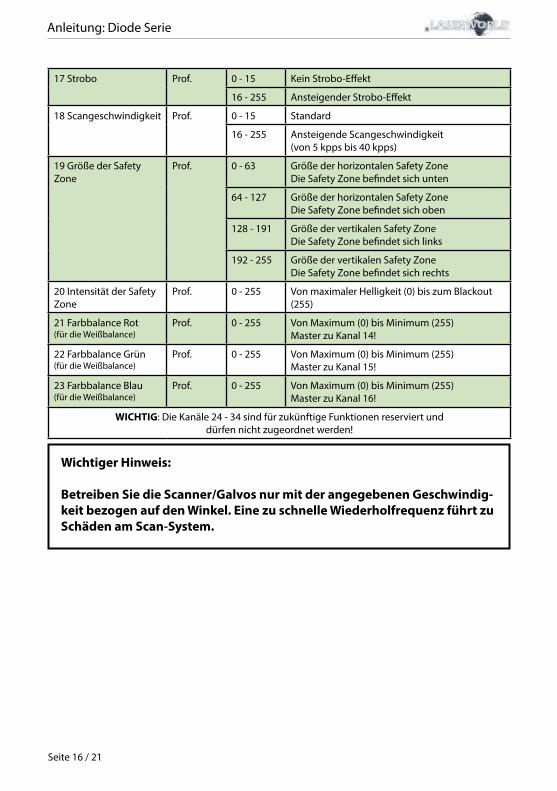
17 Strobo Prof. 0 - 15 Kein Strobo-Effekt
16 - 255 Ansteigender Strobo-Effekt
18 Scangeschwindigkeit Prof. 0 - 15 Standard
16 - 255 Ansteigende Scangeschwindigkeit (von 5 kpps bis 40 kpps)
19 Größe der Safety Zone
Prof. 0 - 63 Größe der horizontalen Safety ZoneDie Safety Zone befindet sich unten
64 - 127 Größe der horizontalen Safety ZoneDie Safety Zone befindet sich oben
128 - 191 Größe der vertikalen Safety ZoneDie Safety Zone befindet sich links
192 - 255 Größe der vertikalen Safety ZoneDie Safety Zone befindet sich rechts
20 Intensität der Safety Zone
Prof. 0 - 255 Von maximaler Helligkeit (0) bis zum Blackout (255)
21 Farbbalance Rot(für die Weißbalance)
Prof. 0 - 255 Von Maximum (0) bis Minimum (255)Master zu Kanal 14!
22 Farbbalance Grün(für die Weißbalance)
Prof. 0 - 255 Von Maximum (0) bis Minimum (255)Master zu Kanal 15!
23 Farbbalance Blau(für die Weißbalance)
Prof. 0 - 255 Von Maximum (0) bis Minimum (255)Master zu Kanal 16!
WICHTIG: Die Kanäle 24 - 34 sind für zukünftige Funktionen reserviert und dürfen nicht zugeordnet werden!
Wichtiger Hinweis:
Betreiben Sie die Scanner/Galvos nur mit der angegebenen Geschwindig-keit bezogen auf den Winkel. Eine zu schnelle Wiederholfrequenz führt zu Schäden am Scan-System.
Anleitung: Diode Serie
Seite 17 / 21
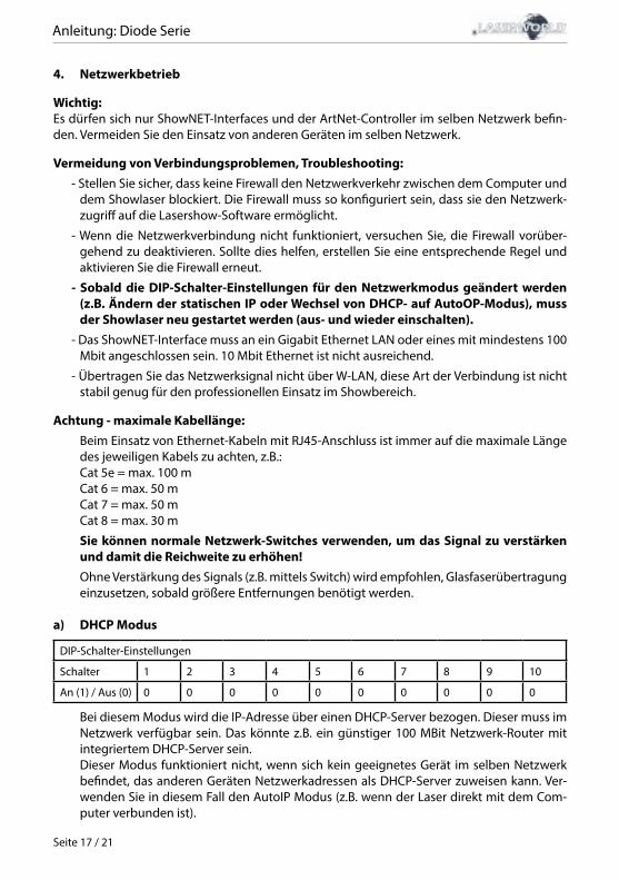
4. Netzwerkbetrieb
Wichtig:Es dürfen sich nur ShowNET-Interfaces und der ArtNet-Controller im selben Netzwerk befin-den. Vermeiden Sie den Einsatz von anderen Geräten im selben Netzwerk.
Vermeidung von Verbindungsproblemen, Troubleshooting:- Stellen Sie sicher, dass keine Firewall den Netzwerkverkehr zwischen dem Computer und
dem Showlaser blockiert. Die Firewall muss so konfiguriert sein, dass sie den Netzwerk-zugriff auf die Lasershow-Software ermöglicht.
- Wenn die Netzwerkverbindung nicht funktioniert, versuchen Sie, die Firewall vorüber-gehend zu deaktivieren. Sollte dies helfen, erstellen Sie eine entsprechende Regel und aktivieren Sie die Firewall erneut.
- Sobald die DIP-Schalter-Einstellungen für den Netzwerkmodus geändert werden (z.B. Ändern der statischen IP oder Wechsel von DHCP- auf AutoOP-Modus), muss der Showlaser neu gestartet werden (aus- und wieder einschalten).
- Das ShowNET-Interface muss an ein Gigabit Ethernet LAN oder eines mit mindestens 100 Mbit angeschlossen sein. 10 Mbit Ethernet ist nicht ausreichend.
- Übertragen Sie das Netzwerksignal nicht über W-LAN, diese Art der Verbindung ist nicht stabil genug für den professionellen Einsatz im Showbereich.
Achtung - maximale Kabellänge:Beim Einsatz von Ethernet-Kabeln mit RJ45-Anschluss ist immer auf die maximale Länge des jeweiligen Kabels zu achten, z.B.:Cat 5e = max. 100 mCat 6 = max. 50 mCat 7 = max. 50 mCat 8 = max. 30 m
Sie können normale Netzwerk-Switches verwenden, um das Signal zu verstärken und damit die Reichweite zu erhöhen!Ohne Verstärkung des Signals (z.B. mittels Switch) wird empfohlen, Glasfaserübertragung einzusetzen, sobald größere Entfernungen benötigt werden.
a) DHCP Modus
DIP-Schalter-Einstellungen
Schalter 1 2 3 4 5 6 7 8 9 10
An (1) / Aus (0) 0 0 0 0 0 0 0 0 0 0
Bei diesem Modus wird die IP-Adresse über einen DHCP-Server bezogen. Dieser muss im Netzwerk verfügbar sein. Das könnte z.B. ein günstiger 100 MBit Netzwerk-Router mit integriertem DHCP-Server sein. Dieser Modus funktioniert nicht, wenn sich kein geeignetes Gerät im selben Netzwerk befindet, das anderen Geräten Netzwerkadressen als DHCP-Server zuweisen kann. Ver-wenden Sie in diesem Fall den AutoIP Modus (z.B. wenn der Laser direkt mit dem Com-puter verbunden ist).
Anleitung: Diode Serie
Seite 18 / 21
b) AutoIP
Schalter 1 2 3 4 5 6 7 8 9 10
An (1) / Aus (0) 0 0 0 0 0 1 0 0 0 0
Bei diesem Modus wird die IP-Adresse automatisch und ohne den Einsatz eines DHCP- Servers vergeben. Ein Windows-PC mit aktiviertem AutoIP ist nötig, um dieses Feature verwenden zu können. In Windows 7, 8 und 10 ist AutoIP standardmäßig aktiviert. In Windows XP muss diese Option manuell eingestellt werden. Bevor sie die ShowNET mit einem Computer verbinden, stellen Sie sicher, dass AutoIP ein-gestellt ist. Sollte sich ein DHCP-Server im Netzwerk befinden (z.B. in einem Router), funk-tioniert AutoIP unter Umständen nicht korrekt. Verwenden Sie dann den DHCP Modus.
c) Statische IP-AdresseDie statische IP-Adresse ist die stabilste Option des Netzwerkbetriebs. Die IP-Adresse besteht aus 4 Zahlenblöcken, die durch einen Punkt abgetrennt sind. Die ersten beiden Zahlenblöcke sind immer 192.168 und können nicht geändert werden. Die hinteren beiden Zahlenblöcke (adr1 and adr2) können mit den Dip-Schaltern modifiziert werden. Die sich ergebende IP-Adresse sollte dieser in etwa gleichen:
192.168.adr1.adr2
Schalter 1 2 3 4 5 6 7 8 9 10
An (1) / Aus (0) 0000 - adr2 = 501000 - adr2 = 510100 - adr2 = 521100 - adr2 = 530010 - adr2 = 541010 - adr2 = 550110 - adr2 = 561110 - adr2 = 570001 - adr2 = 581001 - adr2 = 590101 - adr2 = 601101 - adr2 = 610011 - adr2 = 621011 - adr2 = 630111 - adr2 = 641111 - adr2 = 65
00 - adr1 = 010 - adr1 = 101 - adr1 = 211 - adr1 = 254
1 0 0 0
Der Windows-PC benötigt eine IP-Adresse innerhalb desselben Netzwerk Subnetzes.
Beispiel:
Schalter 1 2 3 4 5 6 7 8 9 10
An (1) / Aus (0) 1 1 0 1 0 0 1 0 0 0
Diese Einstellung würde die IP-Adresse 192.168.0.61 dem Interface zuweisen.Zuweisung einer anderen IP-Adresse innerhalb desselben Subnetzes an den Windows PC, z. B. 192.168.0.100 (Subnetz = 255.255.255.0)
Anleitung: Diode Serie
Seite 19 / 21
d) ILDA-StreamingDas Laserworld ShowNET-Interface kann auch als Reichweitenverlängerung für ILDA-Signale dienen. Ein ankommendes ILDA-Signal wird auf der ILDA-IN-Schnittstelle in ein Standard-UDP-Netzwerksignal umgewandelt über das Netzwerk an eine Empfängerein-heit übertragen und dort wieder in ein Standard-ILDA-Signal umgewandelt (dafür wird als Sender ein externes ShowNET-Interface benötigt!).Übertragen Sie das Netzwerksignal jedoch nicht über W-LAN, diese Art der Verbindung ist nicht stabil genug für den professionellen Einsatz im Showbereich.
Sender-Empfänger Konfiguration für ILDA über LAN, Nutzung als Reichweitenver-längerungDer Sender nutzt den IP-Adressbereich zwischen 192.168.2.70 und 192.168.2.85 und überträgt das Signal zum Empfänger, dessen IP-Adresse zwischen 192.168.2.50 und 192.168.2.65 liegt. Die jeweilige IP-Adresse muss mittels DIP-Schalter festgelegt werden. Bitte stellen Sie sicher, dass sich keine anderen Geräte im selben Netzwerk befinden, die die gleichen IP-Adressräume nutzen.
DIP-Schalter-Einstellungen
Schalter 1 2 3 4 5 6 7 8 9 10
An (1) / Aus (0)
0000 -> IP sender: 192.168.2.70 sendet an 192.168.2.500001 -> IP sender: 192.168.2.71 sendet an 192.168.2.510010 -> IP sender: 192.168.2.72 sendet an 192.168.2.520011 -> IP sender: 192.168.2.73 sendet an 192.168.2.530100 -> IP sender: 192.168.2.74 sendet an 192.168.2.540101-> IP sender: 192.168.2.75 sendet an 192.168.2.550110 -> IP sender: 192.168.2.76 sendet an 192.168.2.560111 -> IP sender: 192.168.2.77 sendet an 192.168.2.571000 -> IP sender: 192.168.2.78 sendet an 192.168.2.581001 -> IP sender: 192.168.2.79 sendet an 192.168.2.591010 -> IP sender: 192.168.2.80 sendet an 192.168.2.601011 -> IP sender: 192.168.2.81 sendet an 192.168.2.611100 -> IP sender: 192.168.2.82 sendet an 192.168.2.621101 -> IP sender: 192.168.2.83 sendet an 192.168.2.631110 -> IP sender: 192.168.2.84 sendet an 192.168.2.641111 -> IP sender: 192.168.2.85 sendet an 192.168.2.65
Sender: 0Empfänger: 1
0 1 1 0 0
Beispiel: Sender IP-Adresseinstellung:
Schalter 1 2 3 4 5 6 7 8 9 10
An (1) / Aus (0) 0 0 0 1 0 0 1 1 0 0
Diese Einstellung weist dem Sender die IP-Adresse 192.168.2.71 zu. Das dazugehörige Empfänger-Interface benötigt daher folgende Adresseinstellung:
Schalter 1 2 3 4 5 6 7 8 9 10
An (1) / Aus (0) 0 0 0 1 1 0 1 1 0 0
Diese Einstellung weist dem Empfänger die IP-Adresse 192.168.2.51 zu.
Der einzige Unterschied zwischen Sender und Empfänger ist die Schaltereinstellung des Schalters mit der Nummer 5, die beim Sender 0, beim Empfänger 1 ist.
Anleitung: Diode Serie
Seite 20 / 21
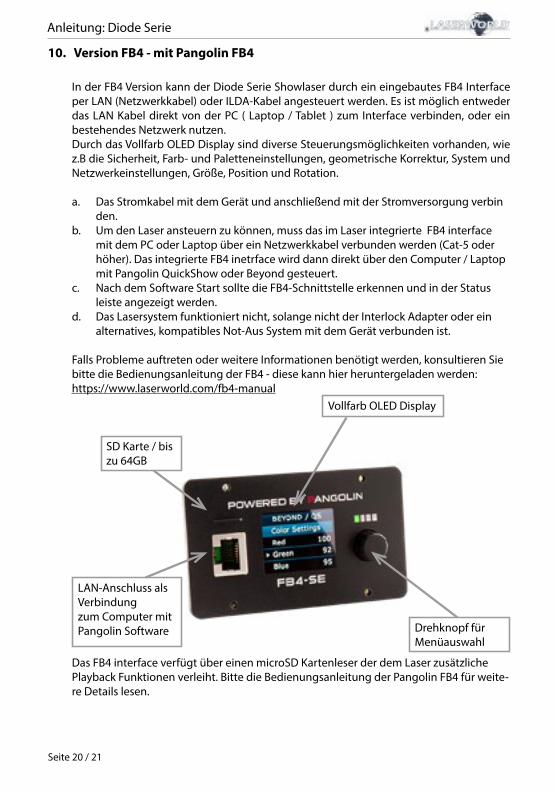
10. Version FB4 - mit Pangolin FB4
In der FB4 Version kann der Diode Serie Showlaser durch ein eingebautes FB4 Interface per LAN (Netzwerkkabel) oder ILDA-Kabel angesteuert werden. Es ist möglich entweder das LAN Kabel direkt von der PC ( Laptop / Tablet ) zum Interface verbinden, oder ein bestehendes Netzwerk nutzen. Durch das Vollfarb OLED Display sind diverse Steuerungsmöglichkeiten vorhanden, wie z.B die Sicherheit, Farb- und Paletteneinstellungen, geometrische Korrektur, System und Netzwerkeinstellungen, Größe, Position und Rotation.
a. Das Stromkabel mit dem Gerät und anschließend mit der Stromversorgung verbin den.b. Um den Laser ansteuern zu können, muss das im Laser integrierte FB4 interface mit dem PC oder Laptop über ein Netzwerkkabel verbunden werden (Cat-5 oder höher). Das integrierte FB4 inetrface wird dann direkt über den Computer / Laptop mit Pangolin QuickShow oder Beyond gesteuert.c. Nach dem Software Start sollte die FB4-Schnittstelle erkennen und in der Status leiste angezeigt werden.d. Das Lasersystem funktioniert nicht, solange nicht der Interlock Adapter oder ein alternatives, kompatibles Not-Aus System mit dem Gerät verbunden ist.
Falls Probleme auftreten oder weitere Informationen benötigt werden, konsultieren Sie bitte die Bedienungsanleitung der FB4 - diese kann hier heruntergeladen werden: https://www.laserworld.com/fb4-manual
SD Karte / bis zu 64GB
LAN-Anschluss als Verbindungzum Computer mit Pangolin Software
Vollfarb OLED Display
Drehknopf für Menüauswahl
Das FB4 interface verfügt über einen microSD Kartenleser der dem Laser zusätzliche Playback Funktionen verleiht. Bitte die Bedienungsanleitung der Pangolin FB4 für weite-re Details lesen.

Anleitung: Diode Serie
Seite 21 / 21
Abschließende Erklärung
Sowohl Produkt als auch Verpackung sind beim Verlassen der Fabrikation einwandfrei.Der Benutzer des Geräts muss die lokalen Sicherheitsbestimmungen und die Warnhinweise in der Betriebsanleitung beachten. Schäden, die durch unsachgemäße Handhabung entstehen, unterliegen nicht dem Einflussbereich der Herstellers und des Händlers. Somit wird keine Haf-tung bzw. Gewährleistung übernommen.Sollten Änderungen an dieser Bedienungsanleitung vorgenommen werden, können wir Sie darüber nicht in Kenntnis setzen. Bitte kontaktieren Sie für Fragen Ihren Händler.Für Servicefragen wenden Sie sich bitte an Ihren Händler oder aber an Laserworld. Verwenden Sie auschließlich Laserworld-Ersatzteile. Änderungen vorbehalten. Aufgrund der Datenmenge kann keine Gewähr für die Richtigkeit der Angaben gegeben werden.
Laserworld (Switzerland) AG Kreuzlingerstrasse 5CH-8574 LengwilSchweiz Verwaltungsrat: Martin Werner Sitz der Gesellschaft: Lengwil / SchweizFirmennummer: CH-440.3.020.548-6Verwaltungsrat: Martin WernerMWSt. Nummer Schweiz: 683 180UID: CHE-113.954.889UST-IdNr: DE 258030001WEEE-Reg.-Nr.: DE [email protected]
representative according to EMVG:Ray Technologies GmbHManaging Director: Martin WernerMühlbachweg 283626 Valley / Germany
Manuel: Série Diode
page 1 / 21
Table des matières:
1. Contenu et informations
2. Avertissements d’usage et précautions avant d’utiliser cet appareil
3. Démarches pour la mise en service, mesures de précaution
4. Instructions de sécurité pour le travail avec l’appareil
5. Soin et entretien
6. Description de l’appareil et mesures de sécurité
7. Comment brancher l’appareil
8. Fonctionnement général
9. Modes d’opérations
10. Version FB4
Explication finale
Informations techniques
Données techniques du laser
Manuel: Série Diode
page 2 / 21
1. Contenu et informations
Nous vous prions de vérifier si vous avez reçu l’intégralité de la marchandise et si la marchan-dise est intacte. Sont compris dans le volume de livraison:
1 x Projecteur laser 2 x Clés 1 x Mode d‘emploi1 x Clé hexagonale 1 x Interlock bridge 1 x Câble d‘alimentation
3. Démarches pour la mise en service, mesures de précaution:
1. Veuillez-vous assurer de brancher l’appareil sur une prise électrique déliv-rant la tension de fonctionnement cor-recte (voire les instructions sur l’appareil ou dans ce mode d’emploi).
2. Veuillez-vous assurer que le laser demeu-re non branché pendant son installation.
3. Cet appareil laser ne doit être installé que par des ouvriers qualifiés en technique selon les normes et règlementations de sécurité des pays respectifs.
4. Veuillez toujours respecter impérati-vement les distances exigées entre l’appareil et les spectateurs. Veillez égale-ment à respecter l’exposition maximale
permise (MPE = maximum permissible exposure).
5. Dans certains pays il est nécessaire de faire certifier l’installation laser par un organisme de vérification agréé.
6. Connectez une fiche interlock ou un in-terrupteur d’urgence facilement acces-sible - pour couper l’arrivée électrique du laser en cas d’urgence.
7. Il est obligatoire de laisser accessible l’alimentation en courant.
8. Lors de l’installation laissez au moins une distance de 15 cm vers le mur et envers d’autres objets.
9. Si vous préférez un montage fixe mural,
2. Avertissements d’usage et précautions avant d’utiliser cet appareil1. Utilisez cet appareil seulement selon ce mode d’emploi.2. L’utilisation est réservée à un usage professionnel selon décret n°2007-665 du 2 mai
2007 relatif à la sécurité des appareils à laser sortant. Article 4 bis : « Les usages spécifiques autorisés pour les appareils à laser sortant d’une
classe supérieure à 2 sont les usages professionnels suivants : (…)9° Spectacle et affichage : Toutes les applications de trajectoire, de visualisation, de projection ou de reproduction d’images en deux ou trois dimensions. »
3. N’utilisez pas cet appareil en cas de dommages visibles sur le boitier du laser ainsi que si le câble d’alimentation est endommagé.
4. Cet appareil ne doit pas être raccordé en permanence au secteur. Débranchez-le du secteur ou éteignez-le à l‘aide de l‘interrupteur d‘alimentation s‘il n‘est pas utilisé.
5. Ne regardez jamais directement le rayon laser quittant l’appareil. Vous risquez de devenir aveugle!
6. Ne pas utiliser cet appareil dans un environnement humide ou pluvieux / poussiéreux.
7. Protéger le laser de l’humidité et des projections d’eau. Aucune bouteille contenant un liquide ne doit être posée sur l’appareil ou à proximité.
En cas de rupture du sigle de garantie, Laserworld décline toute responsabilité et votre appareil ne sera dès lors plus sous garantie!
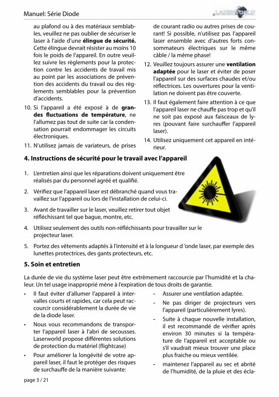
Manuel: Série Diode
page 3 / 21
au plafond ou à des matériaux semblab-les, veuillez ne pas oublier de sécuriser le laser à l’aide d’une élingue de sécurité. Cette élingue devrait résister au moins 10 fois le poids de l’appareil. En outre veuil-lez suivre les règlements pour la protec-tion contre les accidents de travail mis au point par les associations de préven-tion des accidents du travail ou des règ-lements semblables pour la prévention d’accidents.
10. Si l’appareil a été exposé à de gran-des fluctuations de température, ne l’allumez pas tout de suite car la conden-sation pourrait endommager les circuits électroniques.
11. N’utilisez jamais de variateurs, de prises
de courant radio ou autres prises de cou-rant! Si possible, n’utilisez pas l’appareil laser ensemble avec d’autres forts con-sommateurs électriques sur le même câble / la même phase!
12. Veuillez toujours assurer une ventilation adaptée pour le laser et éviter de poser l’appareil sur des surfaces chaudes et/ou réflectrices. Les ouvertures pour la venti-lation ne doivent pas être couverte.
13. Il faut également faire attention à ce que l’appareil laser ne chauffe pas trop et qu’il ne soit pas exposé aux faisceaux de ly-res (pouvant faire surchauffer l’appareil laser).
14. Utilisez uniquement cet appareil en inté-rieur.
4. Instructions de sécurité pour le travail avec l’appareil
1. L‘entretien ainsi que les réparations doivent uniquement être réalisés par du personnel agréé et qualifié.
2. Vérifiez que l’appareil laser est débranché quand vous tra-vaillez sur l’appareil ou lors de l’installation de celui-ci.
3. Avant de travailler sur le laser, veuillez retirer tout objet réfléchissant tel que bague, montre, etc.
4. Utilisez seulement des outils non-réfléchissants pour travailler sur le projecteur laser.
5. Portez des vêtements adaptés à l’intensité et à la longueur d ’onde laser, par exemple des lunettes protectrices, des gants protecteurs, etc.
5. Soin et entretien
La durée de vie du système laser peut être extrêmement raccourcie par l’humidité et la cha-leur. Un tel usage inapproprié mène à l’expiration de tous droits de garantie.
• Il faut éviter d’allumer l’appareil à inter-valles courts et rapides, car cela peut rac-courcir considérablement la durée de vie de la diode laser.
• Nous vous recommandons de transpor-ter l’appareil laser à l’abri de secousses. Laserworld propose différentes solutions de protection du matériel (flightcase)
• Pour améliorer la longévité de votre ap-pareil laser, il faut le protéger des risques de surchauffe de la manière suivante:
- Assurer une ventilation adaptée.
- Ne pas diriger de projecteurs vers l’appareil (particulièrement lyres).
- Suite à chaque nouvelle installation, il est recommandé de vérifier après environ 30 minutes si la tempéra-ture de l’appareil est acceptable ou s’il vaudrait mieux trouver une place plus fraiche ou mieux ventilée.
- maintenez l’appareil au sec et abrité de l’humidité, de la pluie et des écla-
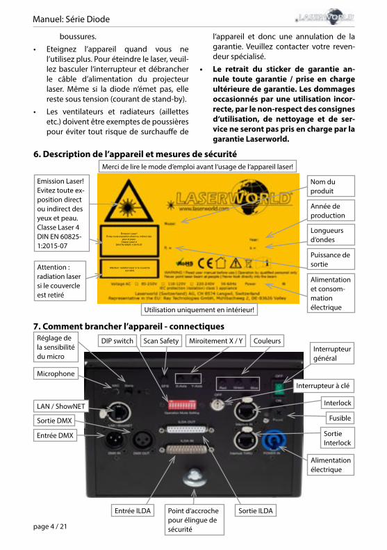
Manuel: Série Diode
page 4 / 21
boussures.
• Eteignez l’appareil quand vous ne l’utilisez plus. Pour éteindre le laser, veuil-lez basculer l‘interrupteur et débrancher le câble d’alimentation du projecteur laser. Même si la diode n’émet pas, elle reste sous tension (courant de stand-by).
• Les ventilateurs et radiateurs (aillettes etc.) doivent être exemptes de poussières pour éviter tout risque de surchauffe de
l‘appareil et donc une annulation de la garantie. Veuillez contacter votre reven-deur spécialisé.
• Le retrait du sticker de garantie an-nule toute garantie / prise en charge ultérieure de garantie. Les dommages occasionnés par une utilisation incor-recte, par le non-respect des consignes d‘utilisation, de nettoyage et de ser-vice ne seront pas pris en charge par la garantie Laserworld.
6. Description de l’appareil et mesures de sécuritéMerci de lire le mode d’emploi avant l‘usage de l‘appareil laser!
Utilisation uniquement en intérieur!
Emission Laser!Evitez toute exposition direct ou indirect des
yeux et peau.Classe Laser 4
DIN EN 60825-1:2015-07
Attention: radiation laser si le couvercle est retiré
Emission Laser!Evitez toute ex-position direct ou indirect des yeux et peau.Classe Laser 4DIN EN 60825-1:2015-07
Attention : radiation laser si le couvercle est retiré
Alimentation et consom-mation électrique
Nom du produit
Longueurs d‘ondes
Puissance de sortie
Année de production
Sortie DMX
Entrée DMX
Entrée ILDA Sortie ILDA
Microphone
Interrupteur à clé
SortieInterlock
Point d‘accroche pour élingue de sécurité
Interrupteur général
Réglage de la sensibilité du micro
Fusible
Interlock
Alimentation électrique
LAN / ShowNET
7. Comment brancher l’appareil - connectiquesCouleursMiroitement X / YScan SafetyDIP switch
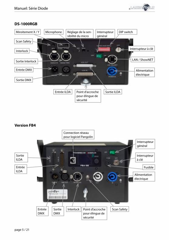
Manuel: Série Diode
page 5 / 21
Version FB4
Sortie DMX
InterlockEntrée DMX
Entrée ILDA
Sortie ILDA
Scan SafetyPoint d‘accroche pour élingue de sécurité
Interrupteur à clé
Connection réseau pour logiciel Pangolin
Interrupteur général
Fusible
Alimentation électrique
DS-1000RGB
Entrée ILDA Sortie ILDAPoint d‘accroche pour élingue de sécurité
Interlock
Sortie Interlock
Entrée DMX
Sortie DMX
Scan Safety
Réglage de la sen-sibilité du micro
Interrupteur général
DIP switch
Interrupteur à clé
LAN / ShowNET
Alimentation électrique
Miroitement X / Y Microphone
Manuel: Série Diode
page 6 / 21
8. Fonctionnement général
1. Alimentation électrique Connectez le câble d‘alimentation avec l‘appareil et l‘alimentation électrique. Il est pri-mordial d‘alimenter l‘appareil avec la bonne tension d‘alimentation car une mauvaise tension d‘alimentation pourra provoquer des dégâts irréparables au projecteur. Les ten-sions d‘alimentations sont listées en fin de mode d‘emploi dans le tableau récapitulatif.Veuillez-vous assurer que la face avant du laser (zone de la fenêtre d‘émission) n‘est pas dirigée vers des personnes ou des objets inflammables lors de la mise sous tension. Pour activer l‘appareil, veuillez connecter le connecteur « interlock » à la prise dédiée, insérer la clé de sécurité et la tourner sur ON, puis allumer l‘appareil. La LED „Emission - Laser on“ sur la face avant de l‘appareil s‘allumera lorsque l‘appareil est prêt à l‘emploi.
2. Interrupteur à cléSur la face arrière du projecteur se situe un interrupteur à clé. L‘émission laser ne pourra qu‘avoir lieu si l’interrupteur à clé (livrée avec le laser) est en position „ON“.Attention: si le laser est laissé sans surveillance, vous nous conseillons de toujours retirer la clé de l‘interrupteur pour éviter toute utilisation non souhaitée par une tierce personne
3. Fusible Sur la face arrière du projecteur se situe un fusible. Si le fusible venait à se déclencher, veuillez le remplacer par un nouveau fusible. Si le problème persiste, veuillez contacter votre revendeur ou le service après-vente de Laserworld.
4. Fonction de sécurité par défautL‘appareil laser possède une „Scan Safety“ (SFS) intégrée. Si le Scan Safety est active (ON), les faisceaux fixes seront bloqués. Lorsque le Scan Safety est desactivé, veillez à respec-ter l’exposition maximale permise (MPE = maximum permissible exposure).
5. X / Y InversionUtilisez les boutons X,Y et/ou X/Y pour inverser voir intervertir les axes de projections (X,Y).
6. Réglage de la sensibilité du microUtilisez le potentiomètre de réglage SOUND pour régler la sensibilité du microphone. Ce réglage est requis pour le mode musical.
7. Couleurs (non disponible pour le DS-1000RGB)Utilisez les potentiomètres de réglages en face arrière pour ajuster la puissance des cou-leurs rouge, vert et bleu.
8. Modes / FonctionsLes différents modes d’opérations sont sélectionnables via les boutons DIP Switch en face arrière de l’appareil. Veuillez noter que tout changement de mode requière un redémarrage du projecteur pour être pris en compte (éteignez le projecteur avec le bouton d’arrêt, changez les DIP Switch puis redémarrez-le). Ne modifiez en aucun cas les boutons DIP Switch avec le projecteur sous tension.
Manuel: Série Diode
page 7 / 21
9. Extinction de l’appareilPour éteindre l’appareil, veuillez actionner l’interrupteur en face arrière, tourner l’interrupteur à clé sur « OFF » et déconnecter le câble d’alimentation.
9. Modes d’opérations / de fonctionnement (La version firmware : 20190520x - Admin tool : v1.33)
Ce projecteur laser offre plusieurs modes de fonctionnement. Il est possible de contrô-ler directement le projecteur laser via un ordinateur et un logiciel show laser, ainsi que de déclencher des effets et animations stockés sur la carte SD interne via une console DMX / ArtNet, ou bien de le laisser fonctionner en mode auto ou en mode musical. Il est également possible d’utiliser un projecteur laser en tant que récepteur pour la transmis-sion en continu (streaming) de signaux ILDA à partir d’une interface ShowNet externe (émetteur).
1. Télécharger le logiciel « Admin tool »Pour tester le projecteur laser ainsi que pour d’autres applications, telles que le té-léchargement de fichiers ILDA sur la carte SD interne, veuillez télécharger le logiciel d’administration « Admin tool » ici : https://www.laserworld.com/shownet_mainboardLancez le fichier « ShowNET-Admin_Tool.exe » chaque fois que ce mode d’emploi fait référence au logiciel d’administration / Admin Tool.IMPORTANT : il est impossible d’accéder au logiciel d’administration lorsque vous accé-dez au projecteur laser via un logiciel tel que Showeditor ou bien Showcontroller. Lors de l’ouverture de l’Admin tool en accédant au projecteur laser en mode de fonctionnement à commande non directe, l’Admin tool vous demandera d’appuyer sur un bouton pour basculer en mode réseau à commande manuelle.
2. Contrôle direct via ordinateura) Contrôle ILDA via interface DAC externe
Le projecteur laser peut être contrôlé via un signal ILDA. Il dispose d’une entrée (ILDA IN) ainsi que d’une sortie (ILDA OUT) à l’arrière de l’appareil. Connectez le projecteur laser à l’interface de contrôle (DAC) à l’aide d’un câble ILDA. Ne connectez pas le laser au port parallèle standard de votre ordinateur mais utilisez toujours une interface ILDA appropri-ée. Après cela, le projecteur laser peut être contrôlé par un logiciel de show laser. Utilisez le connecteur ILDA-through pour chaîner le signal ILDA vers un second projecteur laser.
Puisque ce projecteur laser possède une interface DAC intégrée en tant que carte mère (ShowNET), il est possible de contrôler directement le laser via un réseau local (RJ45) sans avoir à recourir à des câbles ILDA ou à une interface DAC externe.
b) Contrôle direct via logiciel show laser en connexion réseau (LAN)
(1) SHOWEDITOR - logiciel show laser gratuitCe projecteur laser est livré avec une interface réseau intégrée. Le logiciel laser Showedi-tor est inclus gratuitement avec cette carte mère ShowNET. C’est un logiciel de contrôle laser comprenant un mode de contrôle LIVE ainsi que TIMELINE et de nombreux shows laser gratuits sont inclus avec.
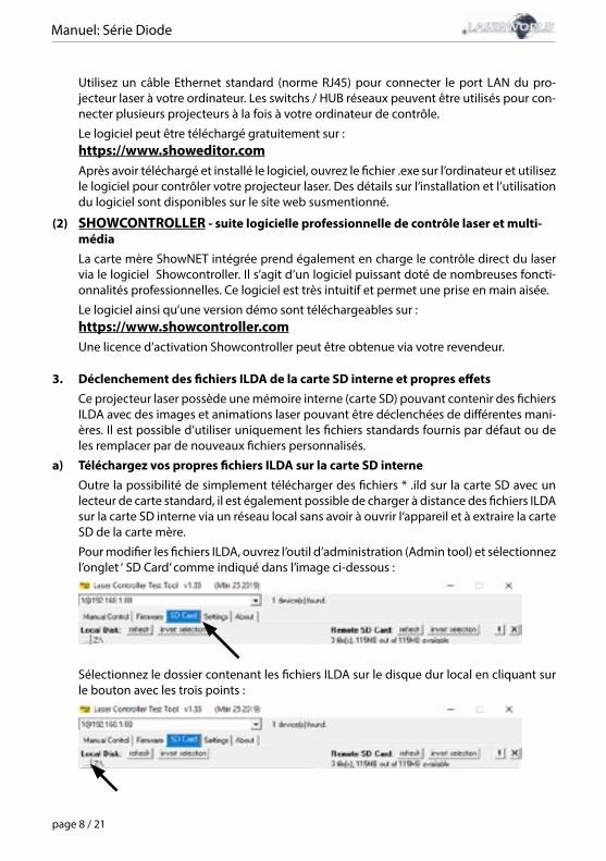
Manuel: Série Diode
page 8 / 21
Utilisez un câble Ethernet standard (norme RJ45) pour connecter le port LAN du pro-jecteur laser à votre ordinateur. Les switchs / HUB réseaux peuvent être utilisés pour con-necter plusieurs projecteurs à la fois à votre ordinateur de contrôle.
Le logiciel peut être téléchargé gratuitement sur :https://www.showeditor.comAprès avoir téléchargé et installé le logiciel, ouvrez le fichier .exe sur l’ordinateur et utilisez le logiciel pour contrôler votre projecteur laser. Des détails sur l’installation et l’utilisation du logiciel sont disponibles sur le site web susmentionné.
(2) SHOWCONTROLLER - suite logicielle professionnelle de contrôle laser et multi-médiaLa carte mère ShowNET intégrée prend également en charge le contrôle direct du laser via le logiciel Showcontroller. Il s’agit d’un logiciel puissant doté de nombreuses foncti-onnalités professionnelles. Ce logiciel est très intuitif et permet une prise en main aisée.
Le logiciel ainsi qu’une version démo sont téléchargeables sur :https://www.showcontroller.comUne licence d’activation Showcontroller peut être obtenue via votre revendeur.
3. Déclenchement des fichiers ILDA de la carte SD interne et propres effets Ce projecteur laser possède une mémoire interne (carte SD) pouvant contenir des fichiers ILDA avec des images et animations laser pouvant être déclenchées de différentes mani-ères. Il est possible d’utiliser uniquement les fichiers standards fournis par défaut ou de les remplacer par de nouveaux fichiers personnalisés.
a) Téléchargez vos propres fichiers ILDA sur la carte SD interneOutre la possibilité de simplement télécharger des fichiers * .ild sur la carte SD avec un lecteur de carte standard, il est également possible de charger à distance des fichiers ILDA sur la carte SD interne via un réseau local sans avoir à ouvrir l‘appareil et à extraire la carte SD de la carte mère.
Pour modifier les fichiers ILDA, ouvrez l’outil d’administration (Admin tool) et sélectionnez l’onglet ‘ SD Card’ comme indiqué dans l’image ci-dessous :
Sélectionnez le dossier contenant les fichiers ILDA sur le disque dur local en cliquant sur le bouton avec les trois points :
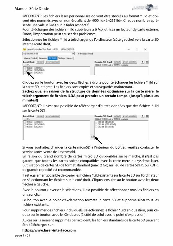
Manuel: Série Diode
page 9 / 21
IMPORTANT: Les fichiers laser personnalisés doivent être stockés au format * .ild et doi-vent être nommés avec un numéro allant de «000.ild» à «255.ild». Chaque nombre repré-sente une valeur DMX sur le fader respectif.Pour télécharger des fichiers * .ild supérieurs à 6 Mo, utilisez un lecteur de carte externe. Sinon, l‘importation peut causer des problèmes.
Sélectionnez les fichiers * .ild à télécharger de l’ordinateur (côté gauche) vers la carte SD interne (côté droit).
Cliquez sur le bouton avec les deux flèches à droite pour télécharger les fichiers * .ild sur la carte SD intégrée. Les fichiers sont copiés et sauvegardés maintenant.Sachez que, en raison de la structure de données optimisée sur la carte mère, le téléchargement de fichiers ILDA peut prendre un certain temps! (jusqu’à plusieurs minutes!)IMPORTANT: Il n‘est pas possible de télécharger d‘autres données que des fichiers * .ild sur la carte SD!
Si vous souhaitez changer la carte microSD à l‘intérieur du boîtier, veuillez contacter le service après-vente de Laserworld.En raison du grand nombre de cartes micro SD disponibles sur le marché, il n’est pas garanti que toutes les cartes soient compatibles avec la carte mère du système laser. L‘utilisation de cartes SD de format standard (max. 2 Go) au lieu de cartes SDHC ou XDHC de grande capacité est recommandée.
Il est également possible de copier les fichiers * .ild existants sur la carte SD sur l‘ordinateur en sélectionnant les fichiers sur le côté droit. Cliquez ensuite sur le bouton avec les deux flèches à gauche.
Avec le bouton «Inverser la sélection», il est possible de sélectionner tous les fichiers en un seul clic.
Le bouton avec le point d‘exclamation formate la carte SD et supprime ainsi tous les fichiers existants.
Pour supprimer des fichiers individuels, sélectionnez le fichier * .ild en question, puis cli-quez sur le bouton avec le «X» dessus (à côté de celui avec le point d’expression).
Au cas où ils seraient supprimés par accident, les fichiers standards de la carte SD peuvent être téléchargés sur
https://www.laser-interface.com
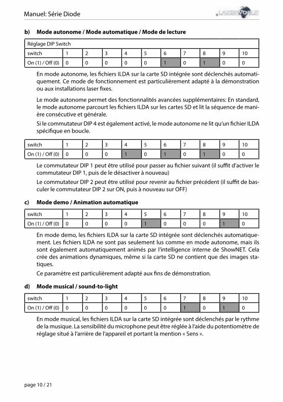
Manuel: Série Diode
page 10 / 21
b) Mode autonome / Mode automatique / Mode de lecture
Réglage DIP Switch
switch 1 2 3 4 5 6 7 8 9 10
On (1) / Off (0) 0 0 0 0 0 1 0 1 0 0
En mode autonome, les fichiers ILDA sur la carte SD intégrée sont déclenchés automati-quement. Ce mode de fonctionnement est particulièrement adapté à la démonstration ou aux installations laser fixes.
Le mode autonome permet des fonctionnalités avancées supplémentaires: En standard, le mode autonome parcourt les fichiers ILDA sur les cartes SD et lit la séquence de mani-ère consécutive et générale.
Si le commutateur DIP 4 est également activé, le mode autonome ne lit qu‘un fichier ILDA spécifique en boucle.
switch 1 2 3 4 5 6 7 8 9 10
On (1) / Off (0) 0 0 0 1 0 1 0 1 0 0
Le commutateur DIP 1 peut être utilisé pour passer au fichier suivant (il suffit d’activer le commutateur DIP 1, puis de le désactiver à nouveau)
Le commutateur DIP 2 peut être utilisé pour revenir au fichier précédent (il suffit de bas-culer le commutateur DIP 2 sur ON, puis à nouveau sur OFF)
c) Mode demo / Animation automatique
switch 1 2 3 4 5 6 7 8 9 10
On (1) / Off (0) 0 0 0 0 1 0 0 0 1 0
En mode demo, les fichiers ILDA sur la carte SD intégrée sont déclenchés automatique-ment. Les fichiers ILDA ne sont pas seulement lus comme en mode autonome, mais ils sont également automatiquement animés par l’intelligence interne de ShowNET. Cela crée des animations dynamiques, même si la carte SD ne contient que des images sta-tiques.
Ce paramètre est particulièrement adapté aux fins de démonstration.
d) Mode musical / sound-to-light
switch 1 2 3 4 5 6 7 8 9 10
On (1) / Off (0) 0 0 0 0 0 0 1 0 1 0
En mode musical, les fichiers ILDA sur la carte SD intégrée sont déclenchés par le rythme de la musique. La sensibilité du microphone peut être réglée à l‘aide du potentiomètre de réglage situé à l‘arrière de l‘appareil et portant la mention « Sens ».
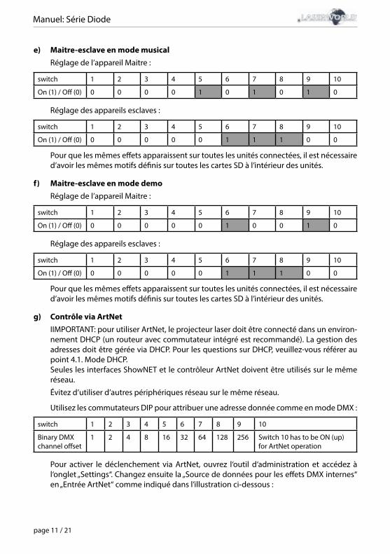
Manuel: Série Diode
page 11 / 21
e) Maitre-esclave en mode musicalRéglage de l’appareil Maitre :
switch 1 2 3 4 5 6 7 8 9 10
On (1) / Off (0) 0 0 0 0 1 0 1 0 1 0
Réglage des appareils esclaves :
switch 1 2 3 4 5 6 7 8 9 10
On (1) / Off (0) 0 0 0 0 0 1 1 1 0 0
Pour que les mêmes effets apparaissent sur toutes les unités connectées, il est nécessaire d’avoir les mêmes motifs définis sur toutes les cartes SD à l’intérieur des unités.
f) Maitre-esclave en mode demoRéglage de l’appareil Maitre :
switch 1 2 3 4 5 6 7 8 9 10
On (1) / Off (0) 0 0 0 0 0 1 0 0 1 0
Réglage des appareils esclaves :
switch 1 2 3 4 5 6 7 8 9 10
On (1) / Off (0) 0 0 0 0 0 1 1 1 0 0
Pour que les mêmes effets apparaissent sur toutes les unités connectées, il est nécessaire d’avoir les mêmes motifs définis sur toutes les cartes SD à l’intérieur des unités.
g) Contrôle via ArtNetIIMPORTANT: pour utiliser ArtNet, le projecteur laser doit être connecté dans un environ-nement DHCP (un routeur avec commutateur intégré est recommandé). La gestion des adresses doit être gérée via DHCP. Pour les questions sur DHCP, veuillez-vous référer au point 4.1. Mode DHCP.Seules les interfaces ShowNET et le contrôleur ArtNet doivent être utilisés sur le même réseau.
Évitez d’utiliser d’autres périphériques réseau sur le même réseau.
Utilisez les commutateurs DIP pour attribuer une adresse donnée comme en mode DMX :
switch 1 2 3 4 5 6 7 8 9 10
Binary DMX channel offset
1 2 4 8 16 32 64 128 256 Switch 10 has to be ON (up) for ArtNet operation
Pour activer le déclenchement via ArtNet, ouvrez l‘outil d‘administration et accédez à l‘onglet „Settings“. Changez ensuite la „Source de données pour les effets DMX internes“ en „Entrée ArtNet“ comme indiqué dans l’illustration ci-dessous :
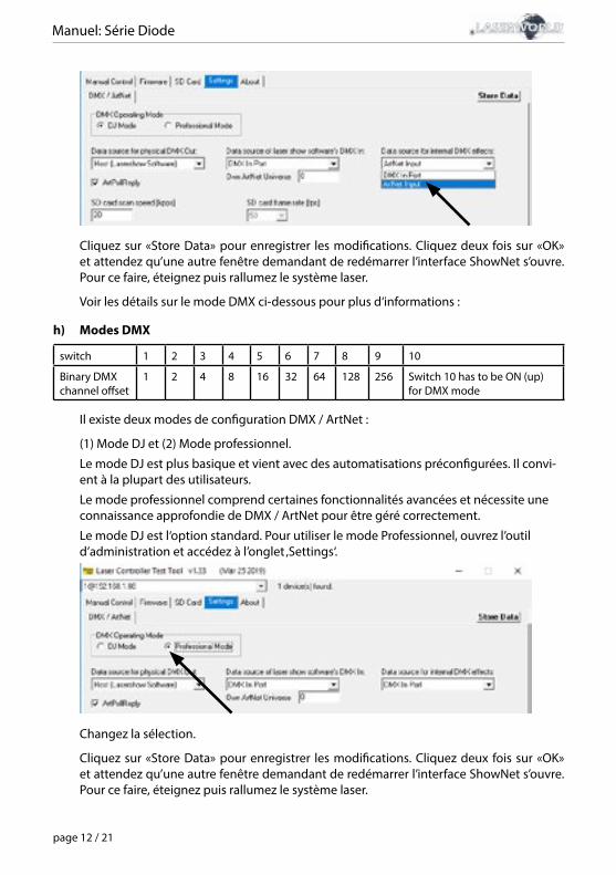
Manuel: Série Diode
page 12 / 21
Cliquez sur «Store Data» pour enregistrer les modifications. Cliquez deux fois sur «OK» et attendez qu’une autre fenêtre demandant de redémarrer l’interface ShowNet s’ouvre. Pour ce faire, éteignez puis rallumez le système laser.
Voir les détails sur le mode DMX ci-dessous pour plus d‘informations :
h) Modes DMX
switch 1 2 3 4 5 6 7 8 9 10
Binary DMX channel offset
1 2 4 8 16 32 64 128 256 Switch 10 has to be ON (up) for DMX mode
Il existe deux modes de configuration DMX / ArtNet :
(1) Mode DJ et (2) Mode professionnel.
Le mode DJ est plus basique et vient avec des automatisations préconfigurées. Il convi-ent à la plupart des utilisateurs.
Le mode professionnel comprend certaines fonctionnalités avancées et nécessite une connaissance approfondie de DMX / ArtNet pour être géré correctement.
Le mode DJ est l‘option standard. Pour utiliser le mode Professionnel, ouvrez l’outil d’administration et accédez à l’onglet ‚Settings‘.
Changez la sélection.
Cliquez sur «Store Data» pour enregistrer les modifications. Cliquez deux fois sur «OK» et attendez qu’une autre fenêtre demandant de redémarrer l’interface ShowNet s’ouvre. Pour ce faire, éteignez puis rallumez le système laser.
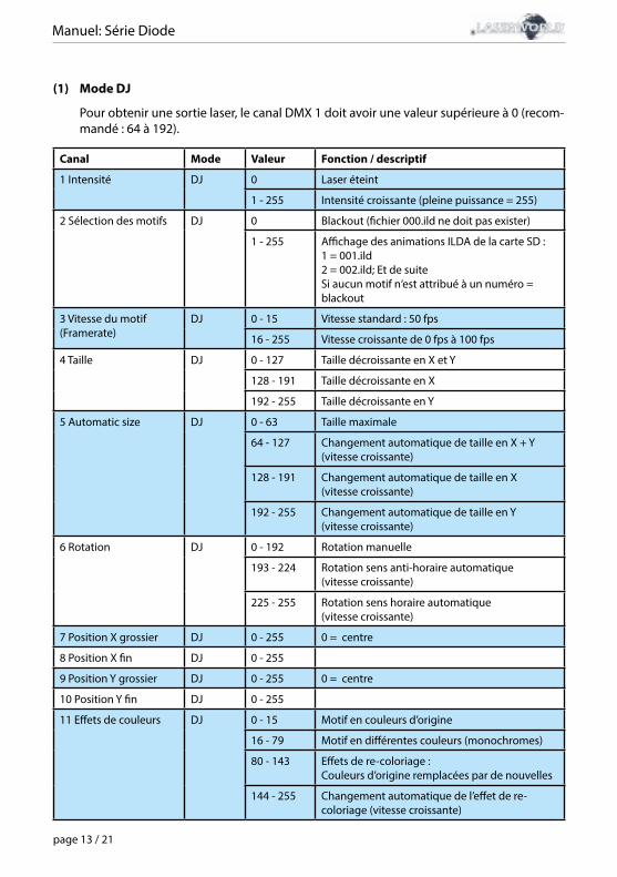
Manuel: Série Diode
page 13 / 21
(1) Mode DJ
Pour obtenir une sortie laser, le canal DMX 1 doit avoir une valeur supérieure à 0 (recom-mandé : 64 à 192).
Canal Mode Valeur Fonction / descriptif
1 Intensité DJ 0 Laser éteint
1 - 255 Intensité croissante (pleine puissance = 255)
2 Sélection des motifs DJ 0 Blackout (fichier 000.ild ne doit pas exister)
1 - 255 Affichage des animations ILDA de la carte SD :1 = 001.ild2 = 002.ild; Et de suiteSi aucun motif n‘est attribué à un numéro = blackout
3 Vitesse du motif(Framerate)
DJ 0 - 15 Vitesse standard : 50 fps
16 - 255 Vitesse croissante de 0 fps à 100 fps
4 Taille DJ 0 - 127 Taille décroissante en X et Y
128 - 191 Taille décroissante en X
192 - 255 Taille décroissante en Y
5 Automatic size DJ 0 - 63 Taille maximale
64 - 127 Changement automatique de taille en X + Y(vitesse croissante)
128 - 191 Changement automatique de taille en X(vitesse croissante)
192 - 255 Changement automatique de taille en Y(vitesse croissante)
6 Rotation DJ 0 - 192 Rotation manuelle
193 - 224 Rotation sens anti-horaire automatique(vitesse croissante)
225 - 255 Rotation sens horaire automatique(vitesse croissante)
7 Position X grossier DJ 0 - 255 0 = centre
8 Position X fin DJ 0 - 255
9 Position Y grossier DJ 0 - 255 0 = centre
10 Position Y fin DJ 0 - 255
11 Effets de couleurs DJ 0 - 15 Motif en couleurs d’origine
16 - 79 Motif en différentes couleurs (monochromes)
80 - 143 Effets de re-coloriage :Couleurs d’origine remplacées par de nouvelles
144 - 255 Changement automatique de l’effet de re-coloriage (vitesse croissante)
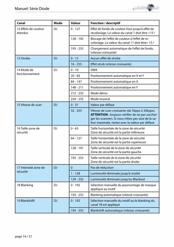
Manuel: Série Diode
page 14 / 21
Canal Mode Valeur Fonction / descriptif
12 Effets de couleurétendus
DJ 0 - 127 Effet de fondu de couleur lisse jusqu’à effet de recoloriage. La valeur du canal 1 doit être >15 !
128 - 192 Blocage de l‘effet de couleur à l‘effet de re-coloriage. La valeur du canal 11 doit être> 15 !
193 - 255 Changement automatique de l’effet de fondu.(vitesse croissante)
13 Strobe DJ 0 - 15 Aucun effet de strobe
16 - 255 Effet strob (vitesse croissante)
14 Mode de fonctionnement
DJ 0 - 19 DMX
20 - 83 Positionnement automatique en X et Y
84 - 147 Positionnement automatique en X
148 - 211 Positionnement automatique en Y
212 - 233 Mode démo
234 - 255 Mode musical
15 Vitesse de scan DJ 0 - 31 Valeur par défaut
32 - 255 Vitesse de scan croissante (de 5kpps à 30kpps). ATTENTION : toujours vérifier de ne pas surchar-ger les scanners. Si vous n’êtes pas sûre de la va-leur maximale, restez avec la valeur par défaut.
16 Taille zone de sécurité
DJ 0 - 63 Taille horizontale de la zone de sécurité Zone de sécurité est la partie inférieure
64 - 127 Taille horizontale de la zone de sécurité Zone de sécurité est la partie supérieure
128 - 191 Taille verticale de la zone de sécurité Zone de sécurité est la partie gauche
192 - 255 Taille verticale de la zone de sécurité Zone de sécurité est la partie droite
17 Intensité zone de sécurité
DJ 0 Pas de réduction
1 - 128 Luminosité diminuée jusqu’à moitié
129 - 255 Luminosité diminuée jusqu’au Blackout
18 Blanking DJ 0 - 192 Sélection manuelle du pourcentage de masque appliqué au motif
193 - 255 Blanking automatique (vitesse croissante)
19 Blankshift DJ 0 - 192 Sélection manuelle du motif ou le blanking du canal 18 est appliqué
193 - 255 Blankshift automatique (vitesse croissante)
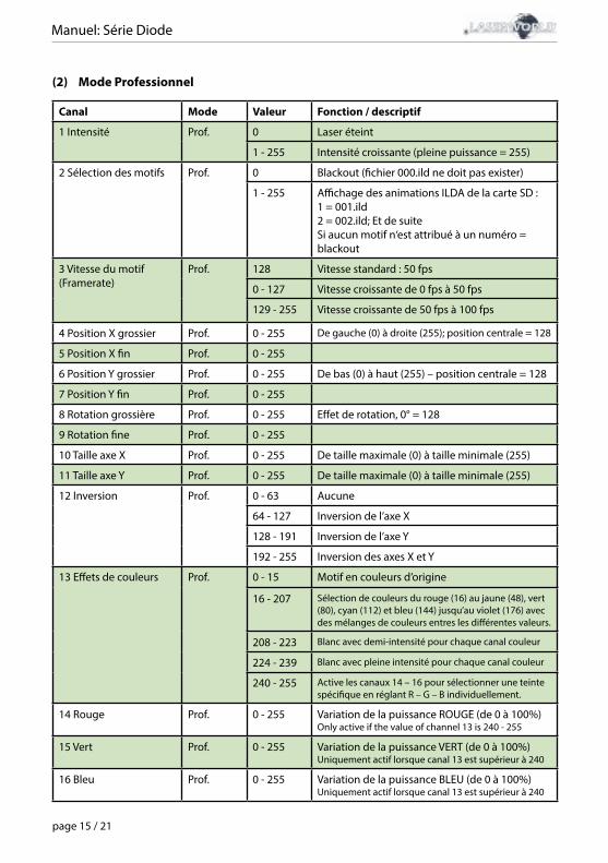
Manuel: Série Diode
page 15 / 21
(2) Mode Professionnel
Canal Mode Valeur Fonction / descriptif
1 Intensité Prof. 0 Laser éteint
1 - 255 Intensité croissante (pleine puissance = 255)
2 Sélection des motifs Prof. 0 Blackout (fichier 000.ild ne doit pas exister)
1 - 255 Affichage des animations ILDA de la carte SD :1 = 001.ild2 = 002.ild; Et de suiteSi aucun motif n‘est attribué à un numéro = blackout
3 Vitesse du motif(Framerate)
Prof. 128 Vitesse standard : 50 fps
0 - 127 Vitesse croissante de 0 fps à 50 fps
129 - 255 Vitesse croissante de 50 fps à 100 fps
4 Position X grossier Prof. 0 - 255 De gauche (0) à droite (255); position centrale = 128
5 Position X fin Prof. 0 - 255
6 Position Y grossier Prof. 0 - 255 De bas (0) à haut (255) – position centrale = 128
7 Position Y fin Prof. 0 - 255
8 Rotation grossière Prof. 0 - 255 Effet de rotation, 0° = 128
9 Rotation fine Prof. 0 - 255
10 Taille axe X Prof. 0 - 255 De taille maximale (0) à taille minimale (255)
11 Taille axe Y Prof. 0 - 255 De taille maximale (0) à taille minimale (255)
12 Inversion Prof. 0 - 63 Aucune
64 - 127 Inversion de l’axe X
128 - 191 Inversion de l’axe Y
192 - 255 Inversion des axes X et Y
13 Effets de couleurs Prof. 0 - 15 Motif en couleurs d’origine
16 - 207 Sélection de couleurs du rouge (16) au jaune (48), vert (80), cyan (112) et bleu (144) jusqu’au violet (176) avec des mélanges de couleurs entres les différentes valeurs.
208 - 223 Blanc avec demi-intensité pour chaque canal couleur
224 - 239 Blanc avec pleine intensité pour chaque canal couleur
240 - 255 Active les canaux 14 – 16 pour sélectionner une teinte spécifique en réglant R – G – B individuellement.
14 Rouge Prof. 0 - 255 Variation de la puissance ROUGE (de 0 à 100%)Only active if the value of channel 13 is 240 - 255
15 Vert Prof. 0 - 255 Variation de la puissance VERT (de 0 à 100%)Uniquement actif lorsque canal 13 est supérieur à 240
16 Bleu Prof. 0 - 255 Variation de la puissance BLEU (de 0 à 100%)Uniquement actif lorsque canal 13 est supérieur à 240
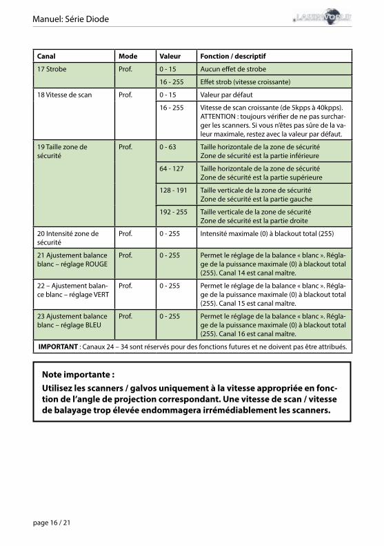
Manuel: Série Diode
page 16 / 21
Canal Mode Valeur Fonction / descriptif
17 Strobe Prof. 0 - 15 Aucun effet de strobe
16 - 255 Effet strob (vitesse croissante)
18 Vitesse de scan Prof. 0 - 15 Valeur par défaut
16 - 255 Vitesse de scan croissante (de 5kpps à 40kpps).ATTENTION : toujours vérifier de ne pas surchar-ger les scanners. Si vous n’êtes pas sûre de la va-leur maximale, restez avec la valeur par défaut.
19 Taille zone de sécurité
Prof. 0 - 63 Taille horizontale de la zone de sécurité Zone de sécurité est la partie inférieure
64 - 127 Taille horizontale de la zone de sécurité Zone de sécurité est la partie supérieure
128 - 191 Taille verticale de la zone de sécurité Zone de sécurité est la partie gauche
192 - 255 Taille verticale de la zone de sécurité Zone de sécurité est la partie droite
20 Intensité zone de sécurité
Prof. 0 - 255 Intensité maximale (0) à blackout total (255)
21 Ajustement balance blanc – réglage ROUGE
Prof. 0 - 255 Permet le réglage de la balance « blanc ». Régla-ge de la puissance maximale (0) à blackout total (255). Canal 14 est canal maître.
22 – Ajustement balan-ce blanc – réglage VERT
Prof. 0 - 255 Permet le réglage de la balance « blanc ». Régla-ge de la puissance maximale (0) à blackout total (255). Canal 15 est canal maître.
23 Ajustement balance blanc – réglage BLEU
Prof. 0 - 255 Permet le réglage de la balance « blanc ». Régla-ge de la puissance maximale (0) à blackout total (255). Canal 16 est canal maître.
IMPORTANT : Canaux 24 – 34 sont réservés pour des fonctions futures et ne doivent pas être attribués.
Note importante :Utilisez les scanners / galvos uniquement à la vitesse appropriée en fonc-tion de l’angle de projection correspondant. Une vitesse de scan / vitesse de balayage trop élevée endommagera irrémédiablement les scanners.
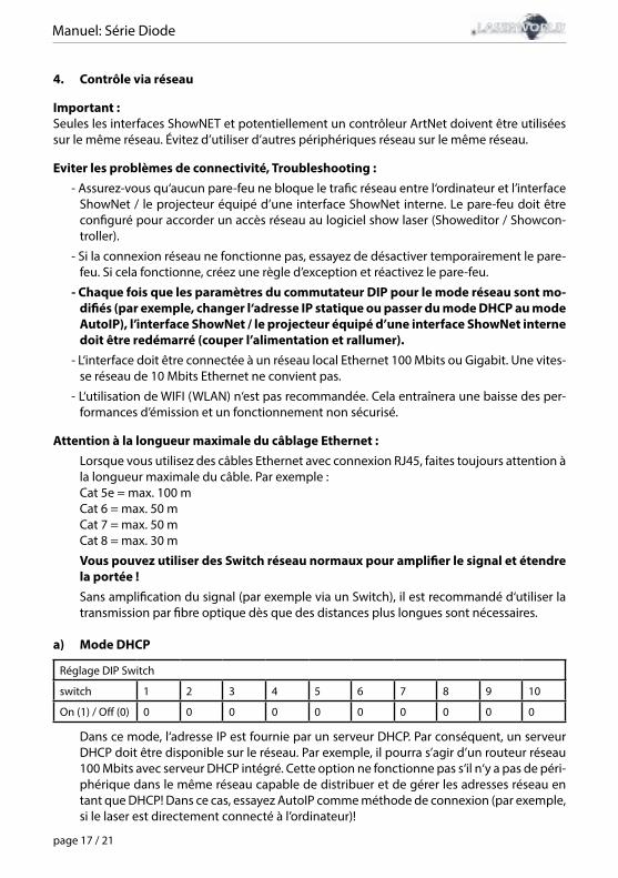
Manuel: Série Diode
page 17 / 21
4. Contrôle via réseau
Important :Seules les interfaces ShowNET et potentiellement un contrôleur ArtNet doivent être utilisées sur le même réseau. Évitez d’utiliser d’autres périphériques réseau sur le même réseau.
Eviter les problèmes de connectivité, Troubleshooting :- Assurez-vous qu‘aucun pare-feu ne bloque le trafic réseau entre l‘ordinateur et l’interface
ShowNet / le projecteur équipé d’une interface ShowNet interne. Le pare-feu doit être configuré pour accorder un accès réseau au logiciel show laser (Showeditor / Showcon-troller).
- Si la connexion réseau ne fonctionne pas, essayez de désactiver temporairement le pare-feu. Si cela fonctionne, créez une règle d’exception et réactivez le pare-feu.
- Chaque fois que les paramètres du commutateur DIP pour le mode réseau sont mo-difiés (par exemple, changer l‘adresse IP statique ou passer du mode DHCP au mode AutoIP), l’interface ShowNet / le projecteur équipé d’une interface ShowNet interne doit être redémarré (couper l’alimentation et rallumer).
- L‘interface doit être connectée à un réseau local Ethernet 100 Mbits ou Gigabit. Une vites-se réseau de 10 Mbits Ethernet ne convient pas.
- L‘utilisation de WIFI (WLAN) n‘est pas recommandée. Cela entraînera une baisse des per-formances d’émission et un fonctionnement non sécurisé.
Attention à la longueur maximale du câblage Ethernet :Lorsque vous utilisez des câbles Ethernet avec connexion RJ45, faites toujours attention à la longueur maximale du câble. Par exemple :Cat 5e = max. 100 mCat 6 = max. 50 mCat 7 = max. 50 mCat 8 = max. 30 m
Vous pouvez utiliser des Switch réseau normaux pour amplifier le signal et étendre la portée !Sans amplification du signal (par exemple via un Switch), il est recommandé d‘utiliser la transmission par fibre optique dès que des distances plus longues sont nécessaires.
a) Mode DHCP
Réglage DIP Switch
switch 1 2 3 4 5 6 7 8 9 10
On (1) / Off (0) 0 0 0 0 0 0 0 0 0 0
Dans ce mode, l‘adresse IP est fournie par un serveur DHCP. Par conséquent, un serveur DHCP doit être disponible sur le réseau. Par exemple, il pourra s’agir d’un routeur réseau 100 Mbits avec serveur DHCP intégré. Cette option ne fonctionne pas s‘il n‘y a pas de péri-phérique dans le même réseau capable de distribuer et de gérer les adresses réseau en tant que DHCP! Dans ce cas, essayez AutoIP comme méthode de connexion (par exemple, si le laser est directement connecté à l’ordinateur)!
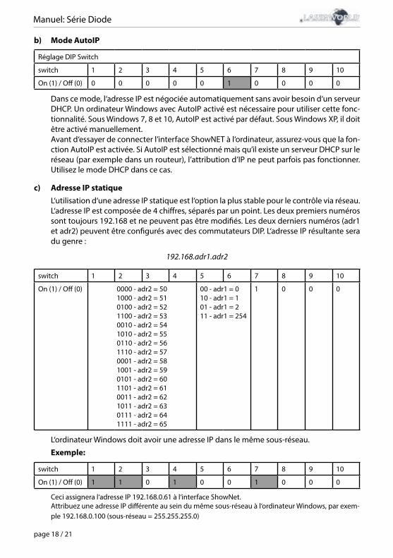
Manuel: Série Diode
page 18 / 21
b) Mode AutoIP
Réglage DIP Switch
switch 1 2 3 4 5 6 7 8 9 10
On (1) / Off (0) 0 0 0 0 0 1 0 0 0 0
Dans ce mode, l‘adresse IP est négociée automatiquement sans avoir besoin d‘un serveur DHCP. Un ordinateur Windows avec AutoIP activé est nécessaire pour utiliser cette fonc-tionnalité. Sous Windows 7, 8 et 10, AutoIP est activé par défaut. Sous Windows XP, il doit être activé manuellement.Avant d‘essayer de connecter l’interface ShowNET à l‘ordinateur, assurez-vous que la fon-ction AutoIP est activée. Si AutoIP est sélectionné mais qu’il existe un serveur DHCP sur le réseau (par exemple dans un routeur), l’attribution d’IP ne peut parfois pas fonctionner. Utilisez le mode DHCP dans ce cas.
c) Adresse IP statiqueL‘utilisation d‘une adresse IP statique est l‘option la plus stable pour le contrôle via réseau. L‘adresse IP est composée de 4 chiffres, séparés par un point. Les deux premiers numéros sont toujours 192.168 et ne peuvent pas être modifiés. Les deux derniers numéros (adr1 et adr2) peuvent être configurés avec des commutateurs DIP. L‘adresse IP résultante sera du genre :
192.168.adr1.adr2
switch 1 2 3 4 5 6 7 8 9 10
On (1) / Off (0) 0000 - adr2 = 501000 - adr2 = 510100 - adr2 = 521100 - adr2 = 530010 - adr2 = 541010 - adr2 = 550110 - adr2 = 561110 - adr2 = 570001 - adr2 = 581001 - adr2 = 590101 - adr2 = 601101 - adr2 = 610011 - adr2 = 621011 - adr2 = 630111 - adr2 = 641111 - adr2 = 65
00 - adr1 = 010 - adr1 = 101 - adr1 = 211 - adr1 = 254
1 0 0 0
L‘ordinateur Windows doit avoir une adresse IP dans le même sous-réseau.
Exemple:
switch 1 2 3 4 5 6 7 8 9 10
On (1) / Off (0) 1 1 0 1 0 0 1 0 0 0
Ceci assignera l‘adresse IP 192.168.0.61 à l‘interface ShowNet.Attribuez une adresse IP différente au sein du même sous-réseau à l‘ordinateur Windows, par exem-ple 192.168.0.100 (sous-réseau = 255.255.255.0)
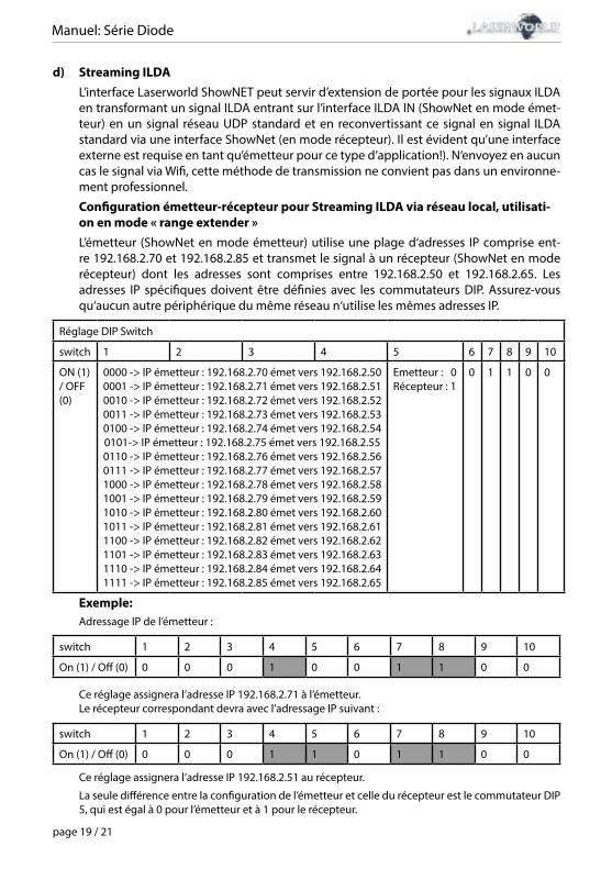
Manuel: Série Diode
page 19 / 21
d) Streaming ILDAL’interface Laserworld ShowNET peut servir d’extension de portée pour les signaux ILDA en transformant un signal ILDA entrant sur l’interface ILDA IN (ShowNet en mode émet-teur) en un signal réseau UDP standard et en reconvertissant ce signal en signal ILDA standard via une interface ShowNet (en mode récepteur). Il est évident qu’une interface externe est requise en tant qu’émetteur pour ce type d’application!). N‘envoyez en aucun cas le signal via Wifi, cette méthode de transmission ne convient pas dans un environne-ment professionnel.
Configuration émetteur-récepteur pour Streaming ILDA via réseau local, utilisati-on en mode « range extender »L’émetteur (ShowNet en mode émetteur) utilise une plage d‘adresses IP comprise ent-re 192.168.2.70 et 192.168.2.85 et transmet le signal à un récepteur (ShowNet en mode récepteur) dont les adresses sont comprises entre 192.168.2.50 et 192.168.2.65. Les adresses IP spécifiques doivent être définies avec les commutateurs DIP. Assurez-vous qu‘aucun autre périphérique du même réseau n‘utilise les mêmes adresses IP.
Réglage DIP Switch
switch 1 2 3 4 5 6 7 8 9 10
ON (1) / OFF (0)
0000 -> IP émetteur : 192.168.2.70 émet vers 192.168.2.500001 -> IP émetteur : 192.168.2.71 émet vers 192.168.2.510010 -> IP émetteur : 192.168.2.72 émet vers 192.168.2.520011 -> IP émetteur : 192.168.2.73 émet vers 192.168.2.530100 -> IP émetteur : 192.168.2.74 émet vers 192.168.2.540101-> IP émetteur : 192.168.2.75 émet vers 192.168.2.550110 -> IP émetteur : 192.168.2.76 émet vers 192.168.2.560111 -> IP émetteur : 192.168.2.77 émet vers 192.168.2.571000 -> IP émetteur : 192.168.2.78 émet vers 192.168.2.581001 -> IP émetteur : 192.168.2.79 émet vers 192.168.2.591010 -> IP émetteur : 192.168.2.80 émet vers 192.168.2.601011 -> IP émetteur : 192.168.2.81 émet vers 192.168.2.611100 -> IP émetteur : 192.168.2.82 émet vers 192.168.2.621101 -> IP émetteur : 192.168.2.83 émet vers 192.168.2.631110 -> IP émetteur : 192.168.2.84 émet vers 192.168.2.641111 -> IP émetteur : 192.168.2.85 émet vers 192.168.2.65
Emetteur : 0Récepteur : 1
0 1 1 0 0
Exemple: Adressage IP de l’émetteur :
switch 1 2 3 4 5 6 7 8 9 10
On (1) / Off (0) 0 0 0 1 0 0 1 1 0 0
Ce réglage assignera l’adresse IP 192.168.2.71 à l’émetteur. Le récepteur correspondant devra avec l’adressage IP suivant :
switch 1 2 3 4 5 6 7 8 9 10
On (1) / Off (0) 0 0 0 1 1 0 1 1 0 0
Ce réglage assignera l’adresse IP 192.168.2.51 au récepteur.
La seule différence entre la configuration de l’émetteur et celle du récepteur est le commutateur DIP 5, qui est égal à 0 pour l’émetteur et à 1 pour le récepteur.
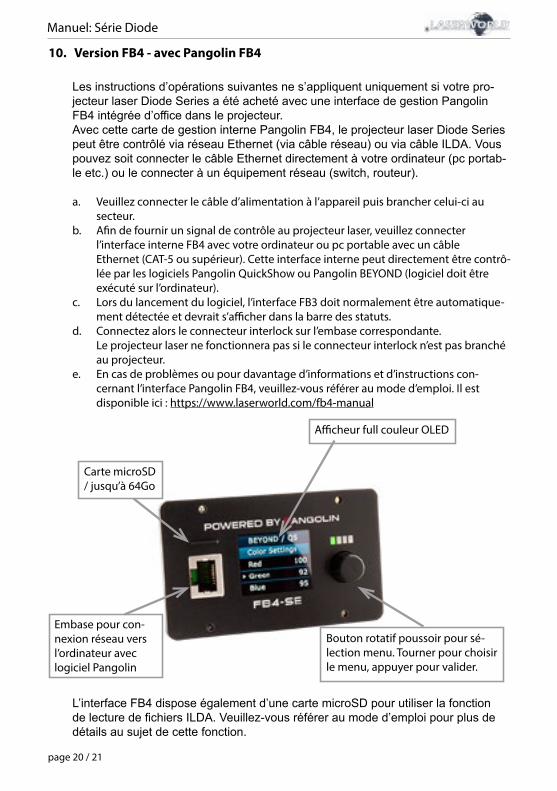
Manuel: Série Diode
page 20 / 21
10. Version FB4 - avec Pangolin FB4
Les instructions d’opérations suivantes ne s’appliquent uniquement si votre pro-jecteur laser Diode Series a été acheté avec une interface de gestion Pangolin FB4 intégrée d’office dans le projecteur. Avec cette carte de gestion interne Pangolin FB4, le projecteur laser Diode Series peut être contrôlé via réseau Ethernet (via câble réseau) ou via câble ILDA. Vous pouvez soit connecter le câble Ethernet directement à votre ordinateur (pc portab-le etc.) ou le connecter à un équipement réseau (switch, routeur).
a. Veuillez connecter le câble d’alimentation à l’appareil puis brancher celui-ci au secteur.b. Afin de fournir un signal de contrôle au projecteur laser, veuillez connecter l’interface interne FB4 avec votre ordinateur ou pc portable avec un câble Ethernet (CAT-5 ou supérieur). Cette interface interne peut directement être contrô- lée par les logiciels Pangolin QuickShow ou Pangolin BEYOND (logiciel doit être exécuté sur l’ordinateur). c. Lors du lancement du logiciel, l’interface FB3 doit normalement être automatique- ment détectée et devrait s’afficher dans la barre des statuts. d. Connectez alors le connecteur interlock sur l’embase correspondante. Le projecteur laser ne fonctionnera pas si le connecteur interlock n’est pas branché au projecteur. e. En cas de problèmes ou pour davantage d’informations et d’instructions con- cernant l’interface Pangolin FB4, veuillez-vous référer au mode d’emploi. Il est disponible ici : https://www.laserworld.com/fb4-manual
Carte microSD / jusqu’à 64Go
Embase pour con-nexion réseau vers l’ordinateur avec logiciel Pangolin
Afficheur full couleur OLED
Bouton rotatif poussoir pour sé-lection menu. Tourner pour choisir le menu, appuyer pour valider.
L’interface FB4 dispose également d’une carte microSD pour utiliser la fonction de lecture de fichiers ILDA. Veuillez-vous référer au mode d’emploi pour plus de détails au sujet de cette fonction.
Manuel: Série Diode
page 21 / 21
Remarque finale
Ce produit, de même que son emballage, sont en parfait état lors de l’envoi. Celui qui utilisecet appareil laser doit respecter les règlements de sécurités locales ainsi que les avertissements expliqués dans notre mode d’emploi. Les dommages qui sont provoqués par une utilisationnon convenable ne peuvent pas être prévus ni par le fabricant ni par le marchand. Par consé-quent la marque décline toute responsabilité ou garantie.En cas de modifications / améliorations de ce mode d’emploi, nous ne pourrons pas vous aver-tir. Veuillez-vous renseigner sur notre site internet ou auprès de votre marchand.Pour les questions liées au service, demandez à votre marchand ou adressez-vous à Laser-world. Utilisez uniquement des pièces de rechange Laserworld. Nous nous réservons le droitd’effectuer des modifications, améliorations à ce mode d’emploi. Laserworld décline toute res-ponsabilité en cas d’inexactitudes ou d’erreurs dans le présent mode d’emploi.
Laserworld (Switzerland) AG Kreuzlingerstrasse 5CH-8574 Lengwil Suisse Conseil d‘administration: Martin Werner Siège social: Lengwil / SuisseNr de société: CH-440.3.020.548-6Conseil d‘administration: Martin WernerMWSt. Nummer Schweiz: 683 180UID: CHE-113.954.889UST-IdNr: DE 258030001WEEE-Reg.-Nr.: DE [email protected]
representative according to EMVG:Ray Technologies GmbHManaging Director: Martin WernerMühlbachweg 283626 Valley / Germany

Manual: Diode Series
Technical data / Technische Daten / caractéristiques techniques
Laser sources:Laserquellen: Sources laser:
Diodes onlyAusschließlich DiodenDiodes uniquement
Laser class:Laserklasse:Classe laser:
4
Scanner: 30 kpps@8°
Scan angle:Strahlauslenkung:Angle de balayage:
45° max.
Operation modes:Betriebsmodi: Mode de fonctionnement:
ILDA, DMX, Stand-alone, Sound-to-Light, Master-SlaveILDA, DMX, Automodus, Musikmodus, Master-SlaveILDA, DMX, mode auto, mode musical, Maître-EsclaveILDA, DMX, network interface Pangolin FB4 (FB4 version)ILDA, DMX, Netzwerkschnittstelle Pangolin FB4 (FB4-Version)ILDA, DMX, interface réseau Pangolin FB4 (version FB4)
Power supply:Stromversorgung: Alimentation:
85 - 250 V AC 50/60 Hz internal
Power consumption:Stromaufnahme: Consommation:
40 W (DS-1000RGB)45 W (DS-2000RGB); 80 W (DS-3000RGB);70 W (DS-1800G); 80 W (DS-3000G);60 W (DS-1600B); 130 W (DS-5500B)
Operating temperature:Betriebstemperatur:Température d‘opération:
+10° to +35°C (non-condensing)
Dimensions:Abmessungen: Dimensions:
200 x 140 x 110 mm (DS-1000RGB)210 x 170 x 145 mm
Weight:Gewicht: Poids:
2.8 kg (DS-1000RGB)3.9 kg (DS-1600B; DS-1800G; DS-3000G) 4.0 kg (DS-2000RGB); 4.3 kg (DS-3000RGB; DS-5500B)
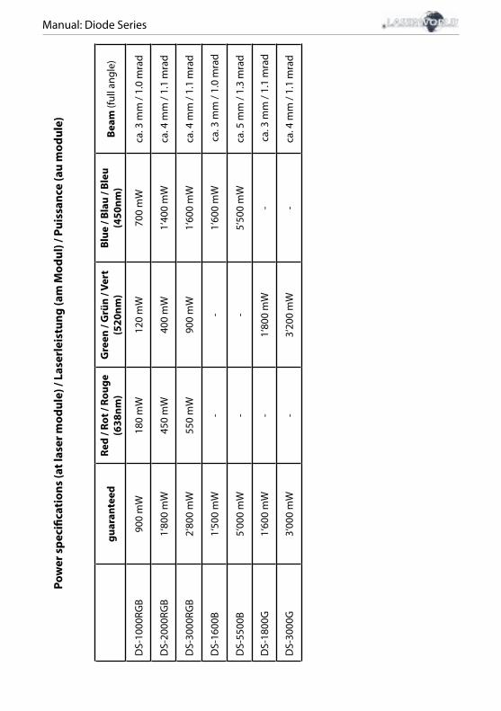
Manual: Diode Series
guar
ante
edRe
d / R
ot /
Roug
e (6
38nm
)G
reen
/ G
rün
/ Ver
t (5
20nm
)Bl
ue /
Blau
/ Bl
eu
(450
nm)
Beam
(ful
l ang
le)
DS-
1000
RGB
900
mW
180
mW
120
mW
700
mW
ca. 3
mm
/ 1.
0 m
rad
DS-
2000
RGB
1‘80
0 m
W45
0 m
W40
0 m
W1‘
400
mW
ca. 4
mm
/ 1.
1 m
rad
DS-
3000
RGB
2‘80
0 m
W55
0 m
W90
0 m
W1‘
600
mW
ca. 4
mm
/ 1.
1 m
rad
DS-
1600
B1‘
500
mW
--
1‘60
0 m
W c
a. 3
mm
/ 1.
0 m
rad
DS-
5500
B5‘
000
mW
--
5‘50
0 m
Wca
. 5 m
m /
1.3
mra
d
DS-
1800
G1‘
600
mW
-1‘
800
mW
- c
a. 3
mm
/ 1.
1 m
rad
DS-
3000
G3‘
000
mW
-3‘
200
mW
-ca
. 4 m
m /
1.1
mra
d
Pow
er s
peci
ficat
ions
(at l
aser
mod
ule)
/ La
serl
eist
ung
(am
Mod
ul) /
Pui
ssan
ce (a
u m
odul
e)