Embed Size (px)
Citation preview
Microwave spectrum of square permalloy dots: Multidomain state
M. Bailleul,1,2,3,* R. Höllinger,2 K. Perzlmaier,2 and C. Fermon3
1Institut de Physique et Chimie des Matériaux de Strasbourg, UMR 7504 ULP-CNRS, 23 rue du Loess BP 43, 67034 Strasbourg Cedex2, France
2Institut für Experimentelle und Angewandte Physik, Universität Regensburg, 93040 Regensburg, Germany3Service de Physique de l’État Condensé, DRECAM/DSM CEA Saclay, Orme des Merisiers, 91191 Gif sur Yvette, France
�Received 23 April 2007; revised manuscript received 27 September 2007; published 3 December 2007�
We provide in this paper a detailed interpretation of the measured and simulated spin-wave spectra forPermalloy square dots in a Landau remanent configuration. Various semianalytical approaches are combined toshow how the domain walls present in the Landau configuration may �i� confine low-frequency spin waves and�ii� set a triangular geometry for the propagation of higher frequency spin waves, which leads to a somehowcounterintuitive quantization process. The knowledge gained from this study is finally used to reconstruct themagnetization process of the dots from the evolution of their microwave spectrum under an applied field.
DOI: 10.1103/PhysRevB.76.224401 PACS number�s�: 75.30.Ds, 76.50.�g, 75.60.Ch
I. INTRODUCTION
The normal modes of the magnetization field in microme-ter size elements �spin-wave modes� have been extensivelystudied for a few years.1 The motivations for this are not onlytechnological �high speed magnetic devices for data process-ing, recording, and sensing� but also fundamental. Indeed, onthe micrometer scale, the dynamics of the magnetizationfield involves a quite subtle interplay between the exchangeand dipolar interactions. This results in several propertiescontrary to the intuition derived from conventional wave me-chanics �waves with nonmonotonic dispersion2 and break-down of Chladni’s law3�.
Up to now, the efforts in the field of dynamic micromag-netism have been concentrated on a few types of magneticground states: rectangular elements in a quasisaturated state�see, e.g., Ref. 4 and references therein� or elliptical elementsin a quasisaturated or vortex state �see, e.g., Refs. 5–8 andreferences therein�. In these cases, the observed normalmodes could be successfully interpreted in terms of quan-tized and localized modes with an additional low-frequencymode associated with the motion of a vortex. However, sev-eral complications are expected when the magnetic groundstate comprises domain walls. Those strongly localized fea-tures are indeed expected to confine and/or to scatter spinwaves9,10 This was confirmed by recent experiments,11–18
where the normal modes have been imaged for the Landauconfiguration.19 In addition to a vortex-motion mode, thesemeasurements revealed a mode strongly confined in the do-main walls and several spin-wave mode features extendingin the domains, the shape of which indicates a sizable influ-ence of the domain walls. With the help of numericsimulations,20–24 those features were qualitatively reproducedand the normal modes were classified according to their sym-metry properties. However, a physical understanding of bothdomain-wall modes and domain modes is still missing. Thispaper aims at providing such a description.
For this purpose, we make use of a microwave absorptionspectrum measured for an assembly of Permalloy square dotsin its remanent state. We first show that this spectrum is wellreproduced by a full micromagnetic simulation for a square
dot in the Landau configuration. In a second time, we pro-pose a set of semianalytical calculations accounting for thedomain-wall modes and domain mode features observed inthe measured and simulated spectra. Note that most of theexperimental, numerical, and theoretical approaches areidentical to those described in Ref. 4, where the same Per-malloy square dots were brought in the quasisaturated stateby applying a high enough magnetic field �10–150 mT�. Inthis respect, the present paper constitutes, therefore, the lowfield counterpart of Ref. 4.
The paper is organized as follows. The experimentalmethod is first described in Sec. II. The measured absorptionpeaks are then reproduced and identified with the help of amicromagnetic simulation �Sec. III�. Sections IV–VI are de-voted to the understanding of these features: While the low-frequency peaks are described within a simple domain-wallresonance framework �Sec. IV�, the high-frequency featuresare attributed to a more complex spin-wave quantization pro-cess, which is analyzed in detail for the simpler case of an“isolated domain” �Sec. V�. For the case of the Landau con-figuration, we show how the symmetry influences this pro-cess �Sec. VI�. Our description of domain and domain-wallmodes is finally applied to the interpretation of the evolutionof the microwave spectrum under the application of a smallmagnetic field �Sec. VII�. A quite general discussion of thenotion of “regularity” for spin-wave spectra is provided inthe Appendix.
II. EXPERIMENTAL SETUP
As in Ref. 4, the system investigated is a row of 103Permalloy square dots having a side w=3 �m, a thicknesst=30 nm, and spaced 3 �m from each other. At remanence,most of these dots exhibit a Landau configuration �see atypical magnetic force microscopy picture in Fig. 1�b��.Their microwave spectrum is measured with the help of afrequency-domain broadband inductive technique. This ex-periment, which is described in detail in Ref. 4, may besummarized as follows: a shorted portion of a coplanarwaveguide is fabricated on top of the row of dots �see amicrophotograph of a small portion of the sample in Fig.
PHYSICAL REVIEW B 76, 224401 �2007�
1098-0121/2007/76�22�/224401�14� ©2007 The American Physical Society224401-1
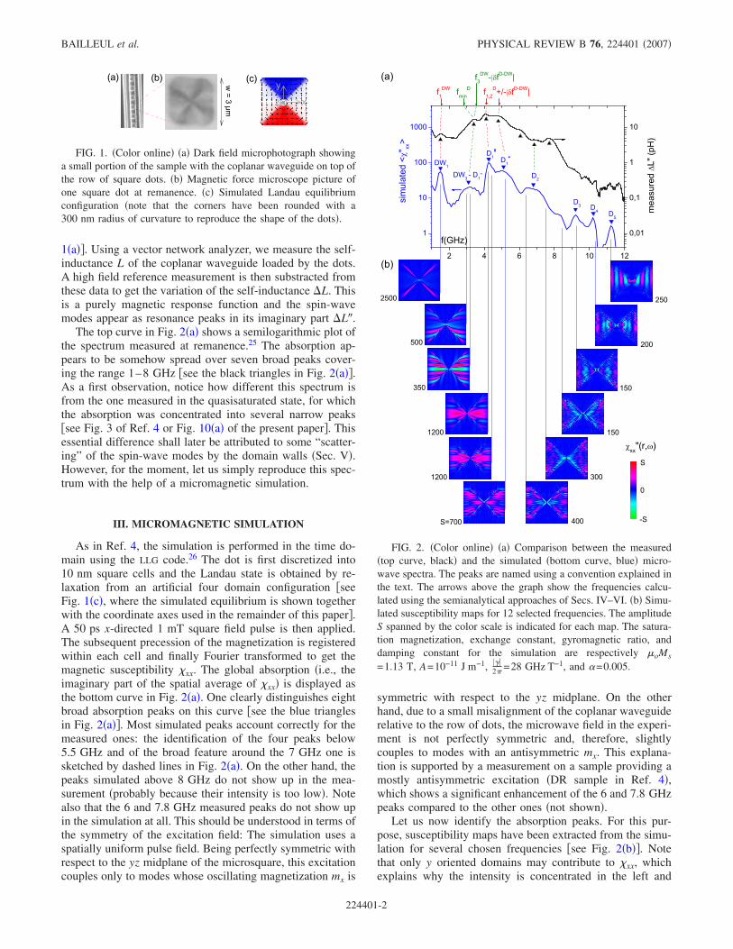
1�a��. Using a vector network analyzer, we measure the self-inductance L of the coplanar waveguide loaded by the dots.A high field reference measurement is then substracted fromthese data to get the variation of the self-inductance �L. Thisis a purely magnetic response function and the spin-wavemodes appear as resonance peaks in its imaginary part �L�.
The top curve in Fig. 2�a� shows a semilogarithmic plot ofthe spectrum measured at remanence.25 The absorption ap-pears to be somehow spread over seven broad peaks cover-ing the range 1–8 GHz �see the black triangles in Fig. 2�a��.As a first observation, notice how different this spectrum isfrom the one measured in the quasisaturated state, for whichthe absorption was concentrated into several narrow peaks�see Fig. 3 of Ref. 4 or Fig. 10�a� of the present paper�. Thisessential difference shall later be attributed to some “scatter-ing” of the spin-wave modes by the domain walls �Sec. V�.However, for the moment, let us simply reproduce this spec-trum with the help of a micromagnetic simulation.
III. MICROMAGNETIC SIMULATION
As in Ref. 4, the simulation is performed in the time do-main using the LLG code.26 The dot is first discretized into10 nm square cells and the Landau state is obtained by re-laxation from an artificial four domain configuration �seeFig. 1�c�, where the simulated equilibrium is shown togetherwith the coordinate axes used in the remainder of this paper�.A 50 ps x-directed 1 mT square field pulse is then applied.The subsequent precession of the magnetization is registeredwithin each cell and finally Fourier transformed to get themagnetic susceptibility �xx. The global absorption �i.e., theimaginary part of the spatial average of �xx� is displayed asthe bottom curve in Fig. 2�a�. One clearly distinguishes eightbroad absorption peaks on this curve �see the blue trianglesin Fig. 2�a��. Most simulated peaks account correctly for themeasured ones: the identification of the four peaks below5.5 GHz and of the broad feature around the 7 GHz one issketched by dashed lines in Fig. 2�a�. On the other hand, thepeaks simulated above 8 GHz do not show up in the mea-surement �probably because their intensity is too low�. Notealso that the 6 and 7.8 GHz measured peaks do not show upin the simulation at all. This should be understood in terms ofthe symmetry of the excitation field: The simulation uses aspatially uniform pulse field. Being perfectly symmetric withrespect to the yz midplane of the microsquare, this excitationcouples only to modes whose oscillating magnetization mx is
symmetric with respect to the yz midplane. On the otherhand, due to a small misalignment of the coplanar waveguiderelative to the row of dots, the microwave field in the experi-ment is not perfectly symmetric and, therefore, slightlycouples to modes with an antisymmetric mx. This explana-tion is supported by a measurement on a sample providing amostly antisymmetric excitation �DR sample in Ref. 4�,which shows a significant enhancement of the 6 and 7.8 GHzpeaks compared to the other ones �not shown�.
Let us now identify the absorption peaks. For this pur-pose, susceptibility maps have been extracted from the simu-lation for several chosen frequencies �see Fig. 2�b��. Notethat only y oriented domains may contribute to �xx, whichexplains why the intensity is concentrated in the left and
FIG. 1. �Color online� �a� Dark field microphotograph showinga small portion of the sample with the coplanar waveguide on top ofthe row of square dots. �b� Magnetic force microscope picture ofone square dot at remanence. �c� Simulated Landau equilibriumconfiguration �note that the corners have been rounded with a300 nm radius of curvature to reproduce the shape of the dots�.
FIG. 2. �Color online� �a� Comparison between the measured�top curve, black� and the simulated �bottom curve, blue� micro-wave spectra. The peaks are named using a convention explained inthe text. The arrows above the graph show the frequencies calcu-lated using the semianalytical approaches of Secs. IV–VI. �b� Simu-lated susceptibility maps for 12 selected frequencies. The amplitudeS spanned by the color scale is indicated for each map. The satura-tion magnetization, exchange constant, gyromagnetic ratio, anddamping constant for the simulation are respectively �oMs
=1.13 T, A=10−11 J m−1, ���2� =28 GHz T−1, and �=0.005.
BAILLEUL et al. PHYSICAL REVIEW B 76, 224401 �2007�
224401-2
right domains.27 Note also the distinct change of the suscep-tibility map when going from one side of the peaks to theother �compare, e.g., the 3 and 3.1 GHz maps or the 4.1 and4.2 GHz ones�. This change is actually observed for all peaksexcept the 1.5 GHz one. Anticipating on the results of Sec.V, this is attributed to the composite nature of these peaks:the spectrum calculated in Sec. V is, indeed, composed ofmany modes whose frequency spacing is of the order of theirintrinsic linewidth �about 125 MHz for in-plane magnetizedPermalloy with �=0.005�. The susceptibility of these modesadd together to form the total susceptibility shown in Fig.2.28 As a consequence, the labeling proposed below shouldbe understood as a peak labeling, but not as a mode labeling.
Starting at the lowest frequency, the first peak appears tobe strongly localized in the domain walls �DW’s�. Because ithas only one antinode along each of them, it is labeled DW1.The map corresponding to the low-frequency part of the sec-ond peak also has maximum intensity in the domain walls.Because one recognizes in this map three antinodes alongeach domain wall, it will be referred to as DW3. All othersusceptibility maps show significant intensity over the wholeleft and right domains �D’s�. The corresponding peaks are,therefore, named Dn, where n describes the degree of inho-mogeneity inside one domain. Following previous works onquantized spin waves, we know that the dispersion of spinwaves is much stronger in the direction perpendicular to theequilibrium magnetization.2,29 So n is chosen as the numberof nodal domains counted perpendicular to the magnetizationof the domains considered �in other words, n−1 is the num-ber of y-directed nodal lines�. There are actually three peaksof the D1 type. The susceptibility map for the lowest fre-quency one �named D1
−� shows about ten x-directed nodallines, while the maps for the two other ones �D1
0 and D1+� are
quite uniform. This frequency ordering is again explained interms of spin-wave quantization: indeed, spin waves propa-gating parallel to the magnetization are known to have aslightly negative dispersion.2,29
The aim of Secs. IV–VI is now to interpret these absorp-tion features in detail. Our attention shall be concentratedonto the four lowest frequency peaks, which are also themost intense ones. For these peaks, the simulated and mea-sured maxima do not differ by more than 300 MHz. In thefollowing, the labels DW1, DW3−D1
- , D10, and D1
+ shall, there-fore, refer indiscriminately to measured and simulated peaks.We shall strive toward a physical description, which, thoughapproximate, should be accurate enough to account quantita-tively for the frequencies of these features. Moreover, wewish this description to account qualitatively for the broad-ness of most of these features and for the appearance of thecorresponding modes. Anticipating the results of the nextsections, the arrows on top of Fig. 2�a� show the frequenciesobtained from our semianalytical calculations �in the follow-ing, the results of these calculations shall be noted fn
D/DW�.Notice the reasonable agreement with the position of the ab-sorption peaks. Let us now start with a simple description ofthe specific dynamics of the domain walls.
IV. DOMAIN-WALL MODES
In order to describe the dynamics of the domain walls,one should first consider their equilibrium configuration. For
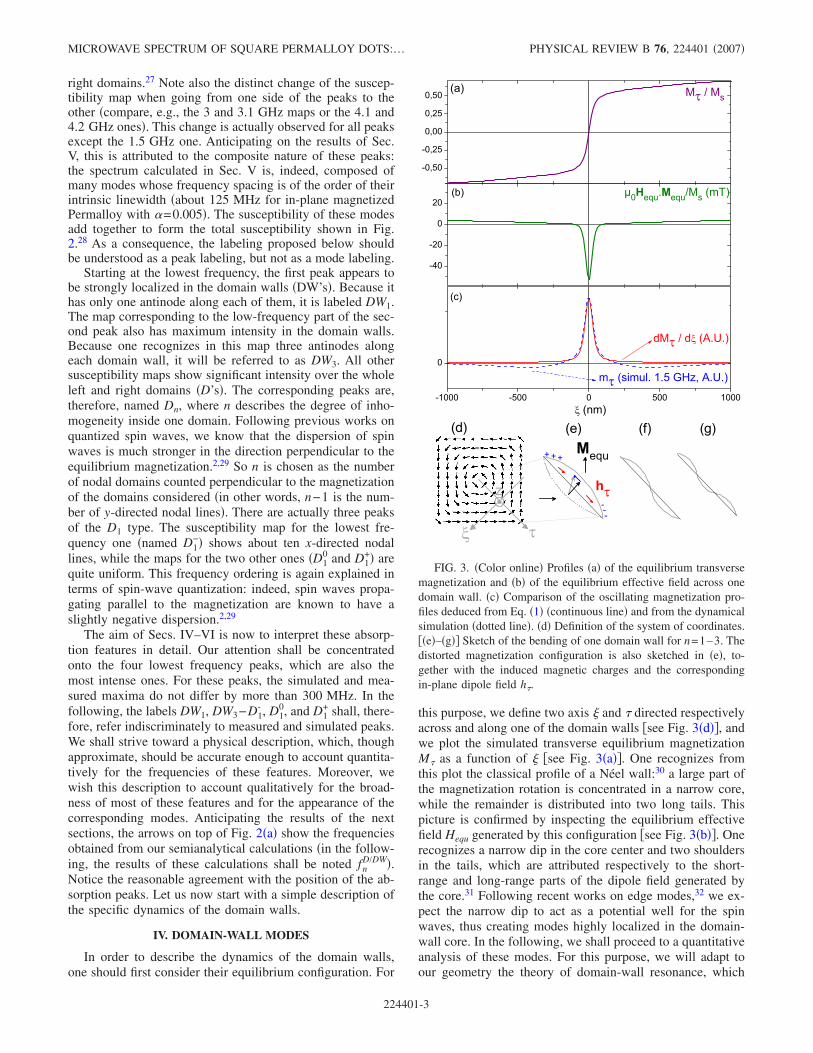
this purpose, we define two axis � and directed respectivelyacross and along one of the domain walls �see Fig. 3�d��, andwe plot the simulated transverse equilibrium magnetizationM as a function of � �see Fig. 3�a��. One recognizes fromthis plot the classical profile of a Néel wall:30 a large part ofthe magnetization rotation is concentrated in a narrow core,while the remainder is distributed into two long tails. Thispicture is confirmed by inspecting the equilibrium effectivefield Hequ generated by this configuration �see Fig. 3�b��. Onerecognizes a narrow dip in the core center and two shouldersin the tails, which are attributed respectively to the short-range and long-range parts of the dipole field generated bythe core.31 Following recent works on edge modes,32 we ex-pect the narrow dip to act as a potential well for the spinwaves, thus creating modes highly localized in the domain-wall core. In the following, we shall proceed to a quantitativeanalysis of these modes. For this purpose, we will adapt toour geometry the theory of domain-wall resonance, which
FIG. 3. �Color online� Profiles �a� of the equilibrium transversemagnetization and �b� of the equilibrium effective field across onedomain wall. �c� Comparison of the oscillating magnetization pro-files deduced from Eq. �1� �continuous line� and from the dynamicalsimulation �dotted line�. �d� Definition of the system of coordinates.��e�–�g�� Sketch of the bending of one domain wall for n=1–3. Thedistorted magnetization configuration is also sketched in �e�, to-gether with the induced magnetic charges and the correspondingin-plane dipole field h.
MICROWAVE SPECTRUM OF SQUARE PERMALLOY DOTS:… PHYSICAL REVIEW B 76, 224401 �2007�
224401-3
was initially developed for bubble and stripe domains.33,34
This provides one with an ansatz for the dynamic magneti-zation, which we then inject into a variational calculation forestimating the mode frequencies.
As the core of the domain wall is much smaller than thedot, we first assume that the domain wall can move withouta major change of its transverse magnetic configuration�which is the basic assumption of domain-wall resonancetheory�.33,34 The dynamic in-plane magnetization m�� ,� is,therefore, obtained by simply shifting the equilibrium wallconfiguration M by a small amount ��:
m��,� = M„� + ��,… − M��,� � ���M
����,� . �1�
This conjecture is confirmed by extracting�M
�� from the equi-librium simulation and comparing it to a � cut of the1.5 GHz simulated mode �see Fig. 3�c��. Both profiles lookvery similar and fit quite well to a �DW=60 nm wide Lorent-zian.
We also assume the wall bending �� to have a sinusoidalprofile and to be pinned both at the corner and at thevortex,35 with a given number of antinodes n in between �seeFigs. 3�e�–3�g��. This allows one to write the following an-satz for the in-plane dynamic magnetization:
m,n��,� = m01
4�2 + �DW2 sin�n�
lDW−
n�
2� . �2�
Here, �DW and lDW= w2
stand respectively for the width andthe length of one domain wall.
Let us now inspect the effective fields created by thisquasistatic motion of the domain-wall core. Because theshort scale structure of the domain wall is preserved, thereare no extra in-plane dipole-exchange fields generated on theshort scale. It is actually the bending of the domain wallwhich generates a nonzero in-plane effective field. As thisdeformation happens on quite a large length scale, this effec-tive field is dominated by a long-range demagnetizing effectwhich occurs as follows: when it bends, the domain wallgenerates extra volume magnetic charges close to its ex-tremities. These charges generate, in turn, a small dipole fieldoriented along the domain wall �h in Fig. 3�e��. Then, themotion of the domain wall also creates a torque whichslightly tilts the magnetization out of the film plane. Thisout-of-plane dynamic magnetization mz generates an effec-tive field hz. For the length scales of our problem �� t��w, where �= 2A
�0Ms2 =5 nm is the exchange length�, hz is
dominated by the large out-of-plane demagnetizing term andmz is simply proportional to m and out-of-phase with respectto it �see, e.g., Appendix A in Ref. 4�.
In a mechanical analogy, h and hz are to be interpreted asa restoring force and an inertia, and their combination deter-mines the mode frequency.4,33,34 This picture is made quan-titative using a variational approach:36–38 we calculate theeffective demagnetizing factors G��� by projecting the ker-
nel of the dipolar interaction G���r ,r��=− �2
�x��x��
1�r−r��
onto theansatz37 mn:
G���n =� dr� dr�m�,n�r�G���r − r��m̄�,n�r��
� drm�,n�r�m̄�,n�r�, �3�
and the mode frequencies are obtained with the help of aKittel-like formula:
fnDW =
���2�
�0MsG�nGzz�n. �4�
This calculation was done numerically by discretizing a300 nm wide area around the domain wall into 60�60 par-allelepipedic cells. We obtain in this way f1
DW=1.6 GHz,f2
DW=2.9 GHz, and f3DW=4.0 GHz. Looking back at Fig. 2�a�,
we see that f1DW accounts perfectly for the DW1 peak. On the
other hand, because of its antisymmetric profile, the n=2mode is not selected by a uniform excitation and, therefore,it does not show up in the susceptibility maps of Fig. 2�b�.Finally, our calculated f3
DW falls 1 GHz above the DW3-D1−
peak. This discrepancy shall be interpreted in Sec. VI as aconsequence of the dynamical coupling between thisdomain-wall mode and the set of domain modes: by account-ing perturbatively for this coupling, we shall obtain a fre-quency f3
DW− ��fD-DW�=3.6 GHz, in better agreement withthe position of the DW3-D1
− peak. Once we have seen how adomain wall generates its own vibration modes,39 let us nowsee how the dynamics of the remainder of the dot is affectedby the presence of domain walls.
V. SPIN-WAVE MODES IN A SATURATED TRIANGULARBODY
In the Landau state, the shape of each domain is a trian-gular one. In this section, we consider, therefore, a fictitiouspreliminary problem consisting of the determination of thequantized spin-wave modes for a saturated and isolated tri-angular body. We shall later see how the domain modes inthe Landau configuration might be connected to the spin-wave modes of such an “isolated” domain �Sec. VI�. We startwith a full numerical diagonalization of the eigensystem�Sec. V A�. The high irregularity of the obtained spectrumindicates that this preliminary problem is already far fromsimple �see the Appendix for an interpretation of this lack ofregularity�. As a consequence, we shall give up trying toderive the frequencies and profiles of single modes. We shallrather describe the spectrum as a whole: On one hand, weshall predict generic properties such as the level spacing andthe minimum frequency with the help of an approximate“adiabatical” quantization procedure �Sec. V B�. On theother hand, we shall estimate the frequency for which themodes couple optimally to a uniform excitation �i.e., the fre-quency of the absorption maximum� with the help of a varia-tional approach �Sec. V C�.
A. Diagonalization
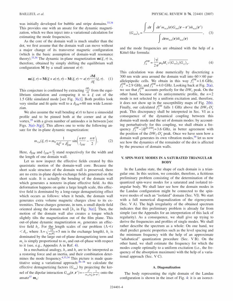
The body representing the right domain of the Landauconfiguration is shown in the inset of Fig. 4: it is an isorect-
BAILLEUL et al. PHYSICAL REVIEW B 76, 224401 �2007�
224401-4
angle triangle with base w=3 �m. Its equilibrium magneti-zation is assumed to be uniformly saturated along its base.40
All the eigenmodes of this problem are calculated using adiagonalization procedure already described in Ref. 4: Thetriangular body is first discretized into 23 nm wide squarecells. By linearizing the Landau-Lifschitz equation, writing itin the frequency domain, and discretizing it, one obtains aneigensystem.41 The system is then solved with the help of aHouseholder reduction and a QL algorithm.42 The couplingof the eigenmodes to a uniform excitation is finally estimatedby calculating the maximum of the spatially averaged sus-ceptibility corresponding to each of them �see Eq. �B9� ofRef. 4�. The obtained spectrum is shown in the main panel ofFig. 4. Note that only modes symmetric with respect to themirroring across the horizontal midaxis of the dots have beenconsidered because antisymmetric modes cannot couple tothe uniform excitation. One sees immediately from Fig. 4that the spectrum does not consist of individual well-resolved peaks but, rather, of a dense series of levels, startingat about 3.5 GHz, reaching a maximum susceptibility around5 GHz, and with a mean level spacing of the order of200 MHz. Inspecting the eigenmodes �see the maps at thebottom of Fig. 4� does not allow one to recognize a clearnodal structure. In particular, one cannot distinguish any qua-siuniform mode: all modes �even the most intense ones� ap-pear to be quite inhomogeneous in the y direction �i.e., par-allel to the equilibrium magnetization�.
Apparently, a finite size body of triangular shape fails inproducing well-defined standing spin-wave features dominat-
ing the absorption spectrum, as observed in the case of rect-angular or elliptical geometries �see, e.g., Refs. 4–6 and 8,and references therein�. This counterintuitive lack of regular-ity is attributed to the interplay between the anisotropic-nonmonotonic character of the spin-wave dispersion and thelow symmetry of the triangular shape. A detailed interpreta-tion of this lack of regularity is provided in the Appendix,where an analogy with the classical motion and the wavemotion in bounded bodies �“billiards”� is proposed, togetherwith an experimental verification relying on the spectra forobliquely magnetized squares. Note that this lack of regular-ity is of practical importance for our present discussion: themean-level spacing of Fig. 4 is of the same order as theintrinsic linewidth of the Permalloy film �125 MHz for �=0.005�, so that individual modes are expected to be re-solved neither in a measurement nor in a realistic micromag-netic simulation including the damping. The spectrum shownin Fig. 4 can, therefore, be seen as a structured quasicon-tinuum, which we shall now describe with the help of sim-plified calculations.
B. Semiclassics
From the conclusions of the last section and from those ofthe Appendix, it is clear that there exists no quantizationprocedure able to describe all normal modes for our geom-etry. However, it is clear that the overall spectrum shouldreflect somehow the shape of the dispersion of the spinwaves and the specific boundary conditions governing theirreflection on the edges. For pedagogical purposes, we pro-pose below an “adiabatical” quantization procedure whichdoes not describe realistically all normal modes, but allowsone to understand better the appearance of the spectrum.
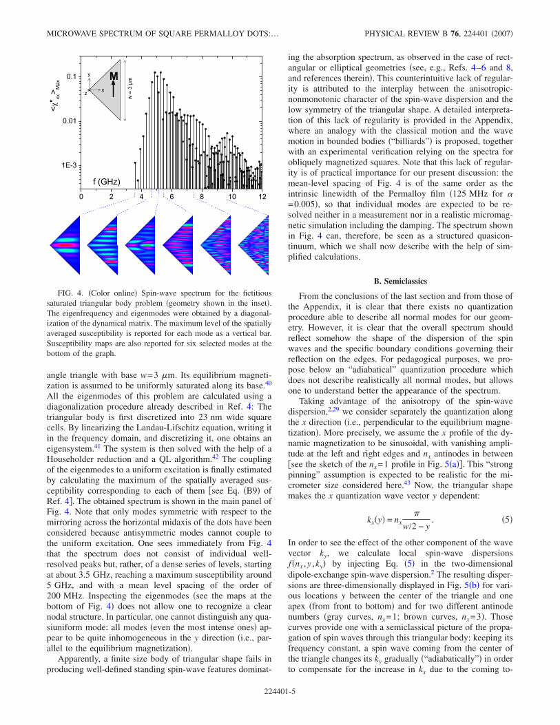
Taking advantage of the anisotropy of the spin-wavedispersion,2,29 we consider separately the quantization alongthe x direction �i.e., perpendicular to the equilibrium magne-tization�. More precisely, we assume the x profile of the dy-namic magnetization to be sinusoidal, with vanishing ampli-tude at the left and right edges and nx antinodes in between�see the sketch of the nx=1 profile in Fig. 5�a��. This “strongpinning” assumption is expected to be realistic for the mi-crometer size considered here.43 Now, the triangular shapemakes the x quantization wave vector y dependent:
kx�y� = nx�
w/2 − y. �5�
In order to see the effect of the other component of the wavevector ky, we calculate local spin-wave dispersionsf�nx ,y ,ky� by injecting Eq. �5� in the two-dimensionaldipole-exchange spin-wave dispersion.2 The resulting disper-sions are three-dimensionally displayed in Fig. 5�b� for vari-ous locations y between the center of the triangle and oneapex �from front to bottom� and for two different antinodenumbers �gray curves, nx=1; brown curves, nx=3�. Thosecurves provide one with a semiclassical picture of the propa-gation of spin waves through this triangular body: keeping itsfrequency constant, a spin wave coming from the center ofthe triangle changes its ky gradually �“adiabatically”� in orderto compensate for the increase in kx due to the coming to-
FIG. 4. �Color online� Spin-wave spectrum for the fictitioussaturated triangular body problem �geometry shown in the inset�.The eigenfrequency and eigenmodes were obtained by a diagonal-ization of the dynamical matrix. The maximum level of the spatiallyaveraged susceptibility is reported for each mode as a vertical bar.Susceptibility maps are also reported for six selected modes at thebottom of the graph.
MICROWAVE SPECTRUM OF SQUARE PERMALLOY DOTS:… PHYSICAL REVIEW B 76, 224401 �2007�
224401-5
gether of the two edges. The minimum frequency �fmin=2.8 GHz� is reached for an nx=1 wave propagating fromthe center of the dot with ky
min 7 2�w �for which the y=0,
nx=1 dispersion has a minimum�. This accounts correctly forthe appearance of the lowest lying calculated eigenmode �3.5 GHz mode in Fig. 4�. As one departs from the conditiony 0 and ky ky
min, the frequency gradually increases �see,e.g., the 4.7 GHz mode in Fig. 4�. The triangular shape may,therefore, be seen as a shallow potential well for each of thenx
th partial wave.To get a global picture of the resulting spectrum, we con-
sider an oscillator problem which reproduces very roughlyour wave-in-a-potential problem: We replace each local dis-persion by a parabolic approximation �see dotted red curvesin Fig. 5�b�� and we also fit the y dependence of the minimaof these approximate dispersions to a parabola �see thedashed red curve in Fig. 5�b��. The resulting approximatesystem �a wave with parabolic dispersion confined in a para-bolic well� is exactly a harmonic oscillator. Solving for it, weobtain a series of levels with a nearly constant spacing of theorder of 200 MHz �see the horizontal bars in Fig. 5�b��, ingood agreement with the mean-level spacing seen in Fig. 4.This calculation illustrates directly the dependence of thespectrum on the size of the triangular body: decreasing thelateral size would increase the curvature of the potential well,resulting in an increase of the level spacing, which couldallow one to resolve individual eigenmodes in a measure-ment or in a realistic micromagnetic simulation. Alterna-tively, decreasing the thickness would decrease the amplitudeof the minimum of the local dispersions, resulting in a de-crease of the number of short-wavelength low-frequencymodes. The global appearance of the spectrum, is therefore,strongly size dependent. From our point of view, this is partof the explanation for the different aspects of the domain
mode spectra reported in Ref. 14 �measurements on0.75–4 �m wide, 16 nm thick squares�, in Ref. 22 �simula-tion on a 1 �m wide, 16 nm thick square�, in Ref. 21 �simu-lation on a 305 nm wide, 20 nm thick square�, in Ref. 24�simulation on a 150 nm wide, 25 nm thick square�, and inthe present paper �measurements and simulations on 3 �mwide, 30 nm thick squares�.
Note that our adiabatical approximation does not allowthe spin wave to switch between different nx, which mayhappen as long as the frequency exceeds the minima of thecorresponding dispersions. This happens actually for some ofthe modes �see, e.g., the 5.1 GHz map in Fig. 4�. At higherfrequencies, one even recognizes a “constant kx” behavior: asone goes from the dot center toward its top corner, the xspacing between nodal lines does not change much, but thenumber of nodal domains fitting between the two edges de-creases gradually �see, e.g., the 9.5 GHz map in Fig. 4�.These different behaviors illustrate again the difficulty tobuild a single rule for predicting the appearance of the spec-trum.
The analysis reported above provides one with a globalpicture of the eigenmodes �what might be called the “spin-wave manifold” of the dot�. However, it does not indicatewhich of these modes are likely to couple to the uniformexcitation used in both the experiment and the simulation,i.e., it does not explain the position of the peak in Fig. 4. Forthis purpose, we shall now resort to a variational approach.
C. Variational estimate
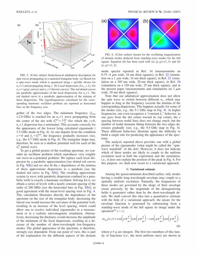
Among the quasicontinuum described earlier, only modeshaving a sizable long-wavelength envelope may couple to aspatially uniform excitation. Naturally, the frequencies ofthese modes are governed by the shape of their envelope�more precisely, by the magnitude of the demagnetizingfields it generates� rather than by the short-wavelength de-tails. We shall convert this idea into a quantitative estimatewith the help of a variational approach: the ansatz for theenvelope function is generated by substracting from astanding-wave mode of the full square its image under theoperation44 x↔y:
mp,q�x,y� = cos�p�x
w�cos�q�
y
w� − cos�q�
x
w�cos�p�
y
w� ,
�6�
where p�q are integers. The first two members of this fam-ily of functions �i.e., the most uniform ones� are shown in
FIG. 5. �Color online� Semiclassical adiabatical description forspin waves propagating in a saturated triangular body. �a� Sketch fora spin-wave mode which is quantized along x �profile shown fornx=1� and propagating along y. �b� Local dispersions f�nx ,y ,ky� fornx=1 �gray curves� and nx=3 �brown curves�. The red dotted curvesare parabolic approximates of the local dispersions for nx=1. Thered dashed curve is a parabolic approximation of the minima ofthese dispersions. The eigenfrequencies calculated for the corre-sponding harmonic oscillator problem are reported as horizontalbars on the frequency axis.
FIG. 6. �Color online� Ansatz for the oscillating magnetizationof domain modes deduced from standing-wave modes for the fullsquare. Equation �6� has been used with �a� �p ,q�= �1,3� and �b��p ,q�= �1,2�.
BAILLEUL et al. PHYSICAL REVIEW B 76, 224401 �2007�
224401-6
( b )( a )
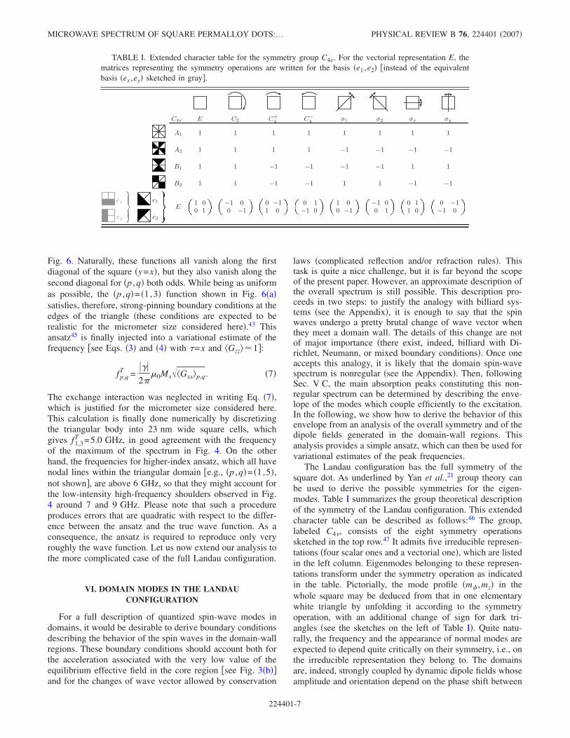
Fig. 6. Naturally, these functions all vanish along the firstdiagonal of the square �y=x�, but they also vanish along thesecond diagonal for �p ,q� both odds. While being as uniformas possible, the �p ,q�= �1,3� function shown in Fig. 6�a�satisfies, therefore, strong-pinning boundary conditions at theedges of the triangle �these conditions are expected to berealistic for the micrometer size considered here�.43 Thisansatz45 is finally injected into a variational estimate of thefrequency �see Eqs. �3� and �4� with =x and Gzz��1�:
fp,qT =
���2�
�0MsGxx�p,q. �7�
The exchange interaction was neglected in writing Eq. �7�,which is justified for the micrometer size considered here.This calculation is finally done numerically by discretizingthe triangular body into 23 nm wide square cells, whichgives f1,3
T =5.0 GHz, in good agreement with the frequencyof the maximum of the spectrum in Fig. 4. On the otherhand, the frequencies for higher-index ansatz, which all havenodal lines within the triangular domain �e.g., �p ,q�= �1,5�,not shown�, are above 6 GHz, so that they might account forthe low-intensity high-frequency shoulders observed in Fig.4 around 7 and 9 GHz. Please note that such a procedureproduces errors that are quadratic with respect to the differ-ence between the ansatz and the true wave function. As aconsequence, the ansatz is required to reproduce only veryroughly the wave function. Let us now extend our analysis tothe more complicated case of the full Landau configuration.
VI. DOMAIN MODES IN THE LANDAUCONFIGURATION
For a full description of quantized spin-wave modes indomains, it would be desirable to derive boundary conditionsdescribing the behavior of the spin waves in the domain-wallregions. These boundary conditions should account both forthe acceleration associated with the very low value of theequilibrium effective field in the core region �see Fig. 3�b��and for the changes of wave vector allowed by conservation
laws �complicated reflection and/or refraction rules�. Thistask is quite a nice challenge, but it is far beyond the scopeof the present paper. However, an approximate description ofthe overall spectrum is still possible. This description pro-ceeds in two steps: to justify the analogy with billiard sys-tems �see the Appendix�, it is enough to say that the spinwaves undergo a pretty brutal change of wave vector whenthey meet a domain wall. The details of this change are notof major importance �there exist, indeed, billiard with Di-richlet, Neumann, or mixed boundary conditions�. Once oneaccepts this analogy, it is likely that the domain spin-wavespectrum is nonregular �see the Appendix�. Then, followingSec. V C, the main absorption peaks constituting this non-regular spectrum can be determined by describing the enve-lope of the modes which couple efficiently to the excitation.In the following, we show how to derive the behavior of thisenvelope from an analysis of the overall symmetry and of thedipole fields generated in the domain-wall regions. Thisanalysis provides a simple ansatz, which can then be used forvariational estimates of the peak frequencies.
The Landau configuration has the full symmetry of thesquare dot. As underlined by Yan et al.,21 group theory canbe used to derive the possible symmetries for the eigen-modes. Table I summarizes the group theoretical descriptionof the symmetry of the Landau configuration. This extendedcharacter table can be described as follows:46 The group,labeled C4�, consists of the eight symmetry operationssketched in the top row.47 It admits five irreducible represen-tations �four scalar ones and a vectorial one�, which are listedin the left column. Eigenmodes belonging to these represen-tations transform under the symmetry operation as indicatedin the table. Pictorially, the mode profile �m� ,mz� in thewhole square may be deduced from that in one elementarywhite triangle by unfolding it according to the symmetryoperation, with an additional change of sign for dark tri-angles �see the sketches on the left of Table I�. Quite natu-rally, the frequency and the appearance of normal modes areexpected to depend quite critically on their symmetry, i.e., onthe irreducible representation they belong to. The domainsare, indeed, strongly coupled by dynamic dipole fields whoseamplitude and orientation depend on the phase shift between
TABLE I. Extended character table for the symmetry group C4v. For the vectorial representation E, thematrices representing the symmetry operations are written for the basis �e1 ,e2� �instead of the equivalentbasis �ex ,ey� sketched in gray�.
C4ν E C2 C+4 C
−
4 σ1 σ2 σx σy
A1 1 1 1 1 1 1 1 1
A2 1 1 1 1 −1 −1 −1 −1
B1 1 1 −1 −1 −1 −1 1 1
B2 1 1 −1 −1 1 1 −1 −1
ex
ey
�
�
�
�
�
�
�
e1
e2
�
�
�
�
�
�
�
E
�
1 0
0 1
� �
−1 0
0 −1
� �
0 −1
1 0
� �
0 1
−1 0
� �
1 0
0 −1
� �
−1 0
0 1
� �
0 1
1 0
� �
0 −1
−1 0
�
MICROWAVE SPECTRUM OF SQUARE PERMALLOY DOTS:… PHYSICAL REVIEW B 76, 224401 �2007�
224401-7
the dynamic magnetization of adjacent domains.21,22
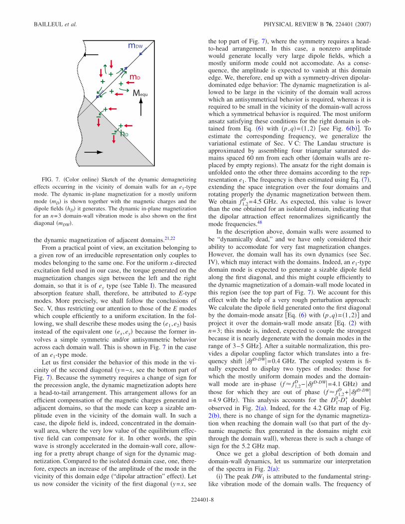
From a practical point of view, an excitation belonging toa given row of an irreducible representation only couples tomodes belonging to the same one. For the uniform x-directedexcitation field used in our case, the torque generated on themagnetization changes sign between the left and the rightdomain, so that it is of ey type �see Table I�. The measuredabsorption feature shall, therefore, be attributed to E-typemodes. More precisely, we shall follow the conclusions ofSec. V, thus restricting our attention to those of the E modeswhich couple efficiently to a uniform excitation. In the fol-lowing, we shall describe these modes using the �e1 ,e2� basisinstead of the equivalent one �ex ,ey� because the former in-volves a simple symmetric and/or antisymmetric behavioracross each domain wall. This is shown in Fig. 7 in the caseof an e1-type mode.
Let us first consider the behavior of this mode in the vi-cinity of the second diagonal �y=−x, see the bottom part ofFig. 7�. Because the symmetry requires a change of sign forthe precession angle, the dynamic magnetization adopts herea head-to-tail arrangement. This arrangement allows for anefficient compensation of the magnetic charges generated inadjacent domains, so that the mode can keep a sizable am-plitude even in the vicinity of the domain wall. In such acase, the dipole field is, indeed, concentrated in the domain-wall area, where the very low value of the equilibrium effec-tive field can compensate for it. In other words, the spinwave is strongly accelerated in the domain-wall core, allow-ing for a pretty abrupt change of sign for the dynamic mag-netization. Compared to the isolated domain case, one, there-fore, expects an increase of the amplitude of the mode in thevicinity of this domain edge �“dipolar attraction” effect�. Letus now consider the vicinity of the first diagonal �y=x, see
the top part of Fig. 7�, where the symmetry requires a head-to-head arrangement. In this case, a nonzero amplitudewould generate locally very large dipole fields, which amostly uniform mode could not accomodate. As a conse-quence, the amplitude is expected to vanish at this domainedge. We, therefore, end up with a symmetry-driven dipolar-dominated edge behavior: The dynamic magnetization is al-lowed to be large in the vicinity of the domain wall acrosswhich an antisymmetrical behavior is required, whereas it isrequired to be small in the vicinity of the domain-wall acrosswhich a symmetrical behavior is required. The most uniformansatz satisfying these conditions for the right domain is ob-tained from Eq. �6� with �p ,q�= �1,2� �see Fig. 6�b��. Toestimate the corresponding frequency, we generalize thevariational estimate of Sec. V C: The Landau structure isapproximated by assembling four triangular saturated do-mains spaced 60 nm from each other �domain walls are re-placed by empty regions�. The ansatz for the right domain isunfolded onto the other three domains according to the rep-resentation e1. The frequency is then estimated using Eq. �7�,extending the space integration over the four domains androtating properly the dynamic magnetization between them.We obtain f1,2
D =4.5 GHz. As expected, this value is lowerthan the one obtained for an isolated domain, indicating thatthe dipolar attraction effect renormalizes significantly themode frequencies.48
In the description above, domain walls were assumed tobe “dynamically dead,” and we have only considered theirability to accomodate for very fast magnetization changes.However, the domain wall has its own dynamics �see Sec.IV�, which may interact with the domains. Indeed, an e1-typedomain mode is expected to generate a sizable dipole fieldalong the first diagonal, and this might couple efficiently tothe dynamic magnetization of a domain-wall mode located inthis region �see the top part of Fig. 7�. We account for thiseffect with the help of a very rough perturbation approach:We calculate the dipole field generated onto the first diagonalby the domain-mode ansatz �Eq. �6� with �p ,q�= �1,2�� andproject it over the domain-wall mode ansatz �Eq. �2� withn=3; this mode is, indeed, expected to couple the strongestbecause it is nearly degenerate with the domain modes in therange of 3–5 GHz�. After a suitable normalization, this pro-vides a dipolar coupling factor which translates into a fre-quency shift ��fD-DW�=0.4 GHz. The coupled system is fi-nally expected to display two types of modes: those forwhich the mostly uniform domain modes and the domain-wall mode are in-phase �f � f1,2
D − ��fD-DW�=4.1 GHz� andthose for which they are out of phase �f � f1,2
D + ��fD-DW�=4.9 GHz�. This analysis accounts for the D1
0-D1+ doublet
observed in Fig. 2�a�. Indeed, for the 4.2 GHz map of Fig.2�b�, there is no change of sign for the dynamic magnetiza-tion when reaching the domain wall �so that part of the dy-namic magnetic flux generated in the domains might exitthrough the domain wall�, whereas there is such a change ofsign for the 5.2 GHz map.
Once we get a global description of both domain anddomain-wall dynamics, let us summarize our interpretationof the spectra in Fig. 2�a�:
�i� The peak DW1 is attributed to the fundamental string-like vibration mode of the domain walls. The frequency of
Mequ
mD
mDW
hD
FIG. 7. �Color online� Sketch of the dynamic demagnetizingeffects occurring in the vicinity of domain walls for an e1-typemode. The dynamic in-plane magnetization for a mostly uniformmode �mD� is shown together with the magnetic charges and thedipole fields �hD� it generates. The dynamic in-plane magnetizationfor an n=3 domain-wall vibration mode is also shown on the firstdiagonal �mDW�.
BAILLEUL et al. PHYSICAL REVIEW B 76, 224401 �2007�
224401-8
this mode is correctly accounted for by Eq. �4� with n=1 �seethe arrow f1
DW above Fig. 2�a��. As this frequency falls farbelow the manifold of domain spin waves, this mode doesnot extend much into the domains. Moreover, the four do-main walls are far enough from each other to neglect theirdirect dipolar coupling.
�ii� The composite peak DW3-D1− is attributed to the bot-
tom of the domain spin-wave manifold coupled to the nDW=3 domain-wall vibration mode, with estimated frequenciesfmin
D =2.8 GHz �see Sec. V B� and f3DW− ��fD-DW�=3.6 GHz.
�iii� Higher frequency peaks are attributed to sets ofmodes selected by the uniform excitation out of a quasicon-tinuum of quantized domain spin waves. The composite fea-ture D1
0-D1+ corresponds to those of the domain modes, which
are as uniform as possible. The splitting is basically associ-ated with the coupling between these modes and the n=3domain-wall vibration mode.
�iv� Features D2–5 are governed by the same mechanismexcept that the envelope functions now involve nodal lineswithin each domain. The amplitudes of these peaks are muchlower than those of the D1 peaks because of the smalleroverlap integrals.
VII. EVOLUTION UNDER AN APPLIED FIELD
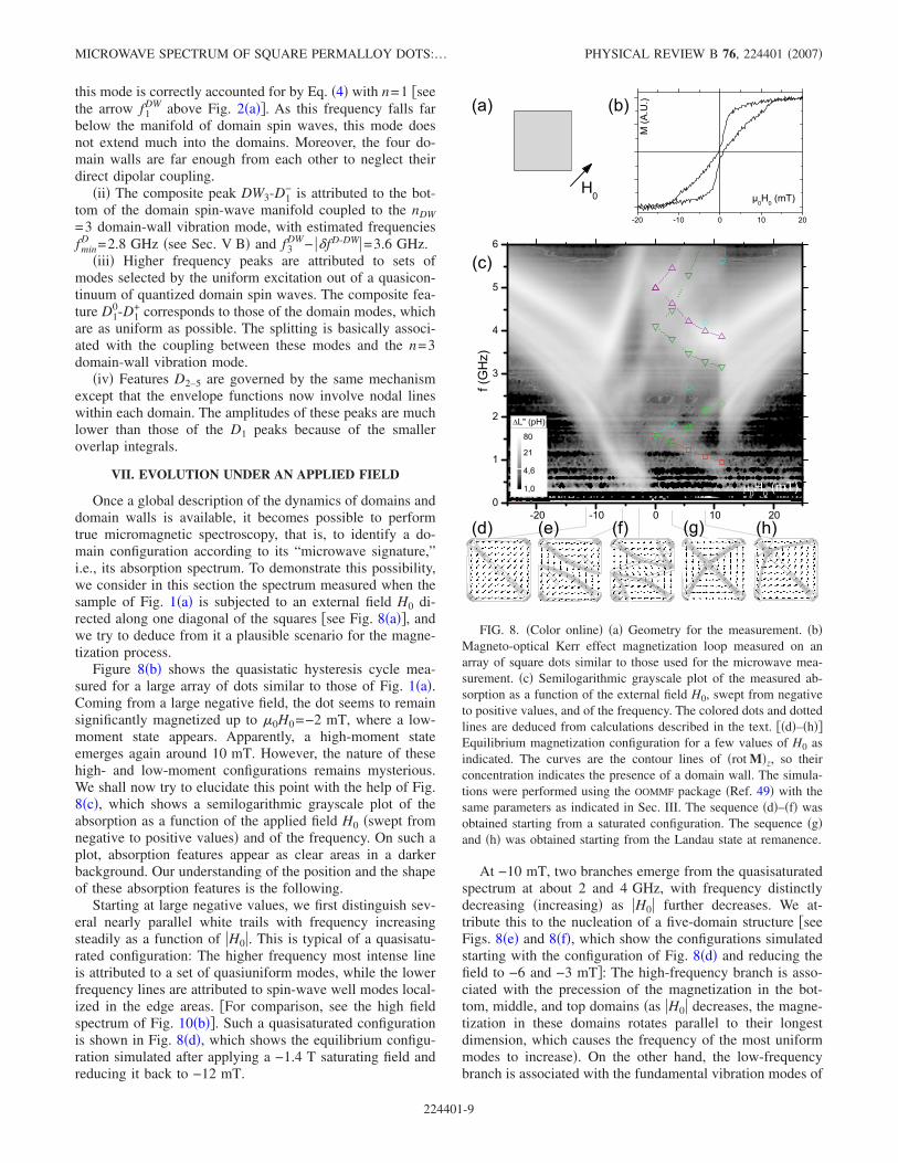
Once a global description of the dynamics of domains anddomain walls is available, it becomes possible to performtrue micromagnetic spectroscopy, that is, to identify a do-main configuration according to its “microwave signature,”i.e., its absorption spectrum. To demonstrate this possibility,we consider in this section the spectrum measured when thesample of Fig. 1�a� is subjected to an external field H0 di-rected along one diagonal of the squares �see Fig. 8�a��, andwe try to deduce from it a plausible scenario for the magne-tization process.
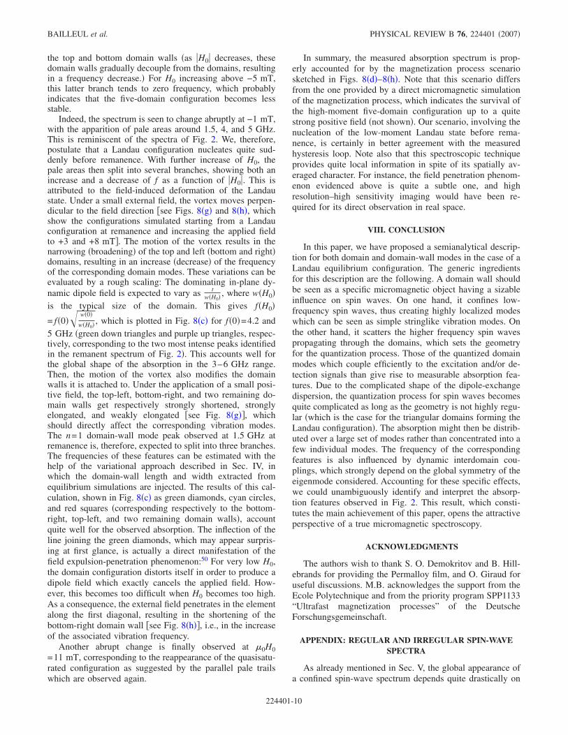
Figure 8�b� shows the quasistatic hysteresis cycle mea-sured for a large array of dots similar to those of Fig. 1�a�.Coming from a large negative field, the dot seems to remainsignificantly magnetized up to �0H0=−2 mT, where a low-moment state appears. Apparently, a high-moment stateemerges again around 10 mT. However, the nature of thesehigh- and low-moment configurations remains mysterious.We shall now try to elucidate this point with the help of Fig.8�c�, which shows a semilogarithmic grayscale plot of theabsorption as a function of the applied field H0 �swept fromnegative to positive values� and of the frequency. On such aplot, absorption features appear as clear areas in a darkerbackground. Our understanding of the position and the shapeof these absorption features is the following.
Starting at large negative values, we first distinguish sev-eral nearly parallel white trails with frequency increasingsteadily as a function of �H0�. This is typical of a quasisatu-rated configuration: The higher frequency most intense lineis attributed to a set of quasiuniform modes, while the lowerfrequency lines are attributed to spin-wave well modes local-ized in the edge areas. �For comparison, see the high fieldspectrum of Fig. 10�b��. Such a quasisaturated configurationis shown in Fig. 8�d�, which shows the equilibrium configu-ration simulated after applying a −1.4 T saturating field andreducing it back to −12 mT.
At −10 mT, two branches emerge from the quasisaturatedspectrum at about 2 and 4 GHz, with frequency distinctlydecreasing �increasing� as �H0� further decreases. We at-tribute this to the nucleation of a five-domain structure �seeFigs. 8�e� and 8�f�, which show the configurations simulatedstarting with the configuration of Fig. 8�d� and reducing thefield to −6 and −3 mT�: The high-frequency branch is asso-ciated with the precession of the magnetization in the bot-tom, middle, and top domains �as �H0� decreases, the magne-tization in these domains rotates parallel to their longestdimension, which causes the frequency of the most uniformmodes to increase�. On the other hand, the low-frequencybranch is associated with the fundamental vibration modes of
FIG. 8. �Color online� �a� Geometry for the measurement. �b�Magneto-optical Kerr effect magnetization loop measured on anarray of square dots similar to those used for the microwave mea-surement. �c� Semilogarithmic grayscale plot of the measured ab-sorption as a function of the external field H0, swept from negativeto positive values, and of the frequency. The colored dots and dottedlines are deduced from calculations described in the text. ��d�–�h��Equilibrium magnetization configuration for a few values of H0 asindicated. The curves are the contour lines of �rot M�z, so theirconcentration indicates the presence of a domain wall. The simula-tions were performed using the OOMMF package �Ref. 49� with thesame parameters as indicated in Sec. III. The sequence �d�–�f� wasobtained starting from a saturated configuration. The sequence �g�and �h� was obtained starting from the Landau state at remanence.
MICROWAVE SPECTRUM OF SQUARE PERMALLOY DOTS:… PHYSICAL REVIEW B 76, 224401 �2007�
224401-9
the top and bottom domain walls �as �H0� decreases, thesedomain walls gradually decouple from the domains, resultingin a frequency decrease.� For H0 increasing above −5 mT,this latter branch tends to zero frequency, which probablyindicates that the five-domain configuration becomes lessstable.
Indeed, the spectrum is seen to change abruptly at −1 mT,with the apparition of pale areas around 1.5, 4, and 5 GHz.This is reminiscent of the spectra of Fig. 2. We, therefore,postulate that a Landau configuration nucleates quite sud-denly before remanence. With further increase of H0, thepale areas then split into several branches, showing both anincrease and a decrease of f as a function of �H0�. This isattributed to the field-induced deformation of the Landaustate. Under a small external field, the vortex moves perpen-dicular to the field direction �see Figs. 8�g� and 8�h�, whichshow the configurations simulated starting from a Landauconfiguration at remanence and increasing the applied fieldto +3 and +8 mT�. The motion of the vortex results in thenarrowing �broadening� of the top and left �bottom and right�domains, resulting in an increase �decrease� of the frequencyof the corresponding domain modes. These variations can beevaluated by a rough scaling: The dominating in-plane dy-namic dipole field is expected to vary as t
w�H0� , where w�H0�is the typical size of the domain. This gives f�H0�
= f�0� w�0�
w�H0� , which is plotted in Fig. 8�c� for f�0�=4.2 and5 GHz �green down triangles and purple up triangles, respec-tively, corresponding to the two most intense peaks identifiedin the remanent spectrum of Fig. 2�. This accounts well forthe global shape of the absorption in the 3–6 GHz range.Then, the motion of the vortex also modifies the domainwalls it is attached to. Under the application of a small posi-tive field, the top-left, bottom-right, and two remaining do-main walls get respectively strongly shortened, stronglyelongated, and weakly elongated �see Fig. 8�g��, whichshould directly affect the corresponding vibration modes.The n=1 domain-wall mode peak observed at 1.5 GHz atremanence is, therefore, expected to split into three branches.The frequencies of these features can be estimated with thehelp of the variational approach described in Sec. IV, inwhich the domain-wall length and width extracted fromequilibrium simulations are injected. The results of this cal-culation, shown in Fig. 8�c� as green diamonds, cyan circles,and red squares �corresponding respectively to the bottom-right, top-left, and two remaining domain walls�, accountquite well for the observed absorption. The inflection of theline joining the green diamonds, which may appear surpris-ing at first glance, is actually a direct manifestation of thefield expulsion-penetration phenomenon:50 For very low H0,the domain configuration distorts itself in order to produce adipole field which exactly cancels the applied field. How-ever, this becomes too difficult when H0 becomes too high.As a consequence, the external field penetrates in the elementalong the first diagonal, resulting in the shortening of thebottom-right domain wall �see Fig. 8�h��, i.e., in the increaseof the associated vibration frequency.
Another abrupt change is finally observed at �0H0=11 mT, corresponding to the reappearance of the quasisatu-rated configuration as suggested by the parallel pale trailswhich are observed again.
In summary, the measured absorption spectrum is prop-erly accounted for by the magnetization process scenariosketched in Figs. 8�d�–8�h�. Note that this scenario differsfrom the one provided by a direct micromagnetic simulationof the magnetization process, which indicates the survival ofthe high-moment five-domain configuration up to a quitestrong positive field �not shown�. Our scenario, involving thenucleation of the low-moment Landau state before rema-nence, is certainly in better agreement with the measuredhysteresis loop. Note also that this spectroscopic techniqueprovides quite local information in spite of its spatially av-eraged character. For instance, the field penetration phenom-enon evidenced above is quite a subtle one, and highresolution–high sensitivity imaging would have been re-quired for its direct observation in real space.
VIII. CONCLUSION
In this paper, we have proposed a semianalytical descrip-tion for both domain and domain-wall modes in the case of aLandau equilibrium configuration. The generic ingredientsfor this description are the following. A domain wall shouldbe seen as a specific micromagnetic object having a sizableinfluence on spin waves. On one hand, it confines low-frequency spin waves, thus creating highly localized modeswhich can be seen as simple stringlike vibration modes. Onthe other hand, it scatters the higher frequency spin wavespropagating through the domains, which sets the geometryfor the quantization process. Those of the quantized domainmodes which couple efficiently to the excitation and/or de-tection signals than give rise to measurable absorption fea-tures. Due to the complicated shape of the dipole-exchangedispersion, the quantization process for spin waves becomesquite complicated as long as the geometry is not highly regu-lar �which is the case for the triangular domains forming theLandau configuration�. The absorption might then be distrib-uted over a large set of modes rather than concentrated into afew individual modes. The frequency of the correspondingfeatures is also influenced by dynamic interdomain cou-plings, which strongly depend on the global symmetry of theeigenmode considered. Accounting for these specific effects,we could unambiguously identify and interpret the absorp-tion features observed in Fig. 2. This result, which consti-tutes the main achievement of this paper, opens the attractiveperspective of a true micromagnetic spectroscopy.
ACKNOWLEDGMENTS
The authors wish to thank S. O. Demokritov and B. Hill-ebrands for providing the Permalloy film, and O. Giraud foruseful discussions. M.B. acknowledges the support from theEcole Polytechnique and from the priority program SPP1133“Ultrafast magnetization processes” of the DeutscheForschungsgemeinschaft.
APPENDIX: REGULAR AND IRREGULAR SPIN-WAVESPECTRA
As already mentioned in Sec. V, the global appearance ofa confined spin-wave spectrum depends quite drastically on
BAILLEUL et al. PHYSICAL REVIEW B 76, 224401 �2007�
224401-10
the amount of symmetry of the confining body. The aim ofthis appendix is to make this rather vague assertion moreprecise with the help of an analogy. For this purpose, we firstquote some results on the regularity of the motion in billiardsystems. We then show how to identify qualitatively a spin-wave problem to a classical billiard one. Finally, we providean experimental illustration of the relevance of the notion ofregularity for spin-wave spectra.
1. Classical billiards and wave billiards
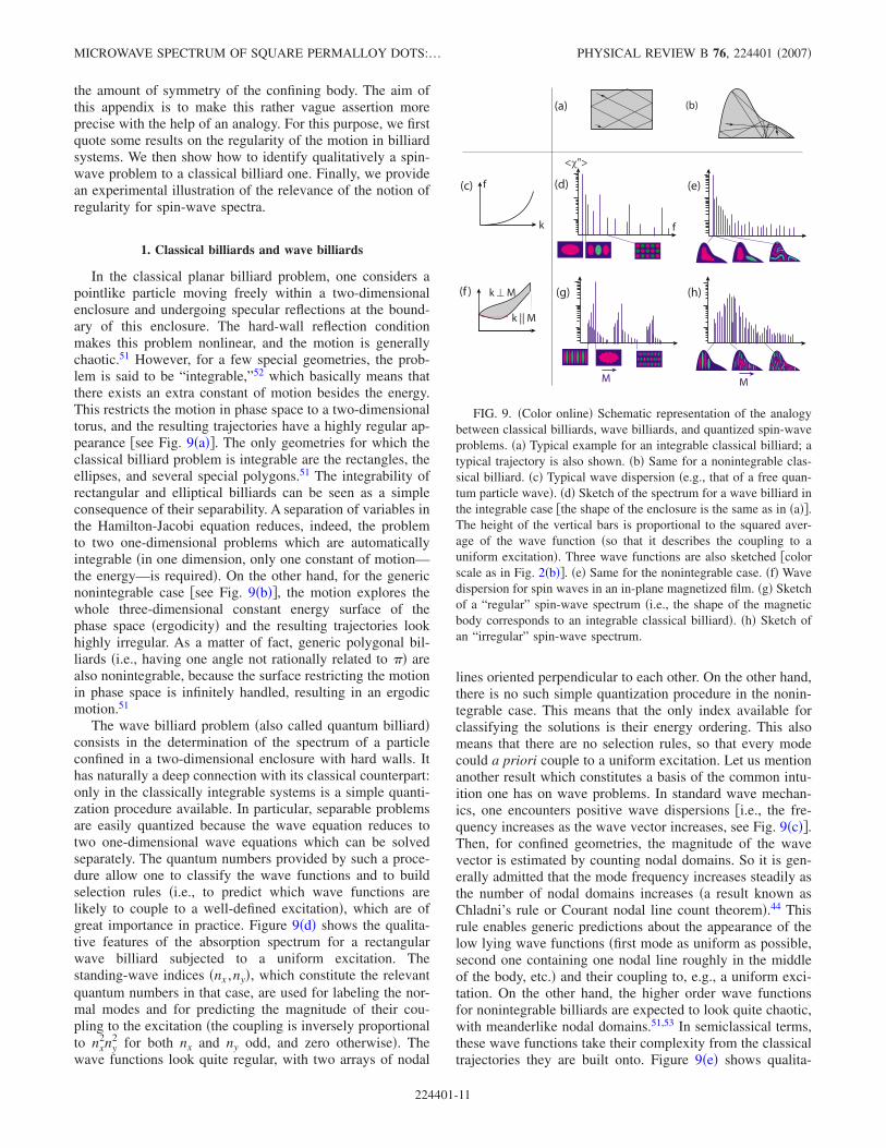
In the classical planar billiard problem, one considers apointlike particle moving freely within a two-dimensionalenclosure and undergoing specular reflections at the bound-ary of this enclosure. The hard-wall reflection conditionmakes this problem nonlinear, and the motion is generallychaotic.51 However, for a few special geometries, the prob-lem is said to be “integrable,”52 which basically means thatthere exists an extra constant of motion besides the energy.This restricts the motion in phase space to a two-dimensionaltorus, and the resulting trajectories have a highly regular ap-pearance �see Fig. 9�a��. The only geometries for which theclassical billiard problem is integrable are the rectangles, theellipses, and several special polygons.51 The integrability ofrectangular and elliptical billiards can be seen as a simpleconsequence of their separability. A separation of variables inthe Hamilton-Jacobi equation reduces, indeed, the problemto two one-dimensional problems which are automaticallyintegrable �in one dimension, only one constant of motion—the energy—is required�. On the other hand, for the genericnonintegrable case �see Fig. 9�b��, the motion explores thewhole three-dimensional constant energy surface of thephase space �ergodicity� and the resulting trajectories lookhighly irregular. As a matter of fact, generic polygonal bil-liards �i.e., having one angle not rationally related to �� arealso nonintegrable, because the surface restricting the motionin phase space is infinitely handled, resulting in an ergodicmotion.51
The wave billiard problem �also called quantum billiard�consists in the determination of the spectrum of a particleconfined in a two-dimensional enclosure with hard walls. Ithas naturally a deep connection with its classical counterpart:only in the classically integrable systems is a simple quanti-zation procedure available. In particular, separable problemsare easily quantized because the wave equation reduces totwo one-dimensional wave equations which can be solvedseparately. The quantum numbers provided by such a proce-dure allow one to classify the wave functions and to buildselection rules �i.e., to predict which wave functions arelikely to couple to a well-defined excitation�, which are ofgreat importance in practice. Figure 9�d� shows the qualita-tive features of the absorption spectrum for a rectangularwave billiard subjected to a uniform excitation. Thestanding-wave indices �nx ,ny�, which constitute the relevantquantum numbers in that case, are used for labeling the nor-mal modes and for predicting the magnitude of their cou-pling to the excitation �the coupling is inversely proportionalto nx
2ny2 for both nx and ny odd, and zero otherwise�. The
wave functions look quite regular, with two arrays of nodal
lines oriented perpendicular to each other. On the other hand,there is no such simple quantization procedure in the nonin-tegrable case. This means that the only index available forclassifying the solutions is their energy ordering. This alsomeans that there are no selection rules, so that every modecould a priori couple to a uniform excitation. Let us mentionanother result which constitutes a basis of the common intu-ition one has on wave problems. In standard wave mechan-ics, one encounters positive wave dispersions �i.e., the fre-quency increases as the wave vector increases, see Fig. 9�c��.Then, for confined geometries, the magnitude of the wavevector is estimated by counting nodal domains. So it is gen-erally admitted that the mode frequency increases steadily asthe number of nodal domains increases �a result known asChladni’s rule or Courant nodal line count theorem�.44 Thisrule enables generic predictions about the appearance of thelow lying wave functions �first mode as uniform as possible,second one containing one nodal line roughly in the middleof the body, etc.� and their coupling to, e.g., a uniform exci-tation. On the other hand, the higher order wave functionsfor nonintegrable billiards are expected to look quite chaotic,with meanderlike nodal domains.51,53 In semiclassical terms,these wave functions take their complexity from the classicaltrajectories they are built onto. Figure 9�e� shows qualita-
f
k
(a) (b)
(c) (e)
(h)(g)(f )
M M
k ⊥ M
k || M
f
<χ">
(d)
FIG. 9. �Color online� Schematic representation of the analogybetween classical billiards, wave billiards, and quantized spin-waveproblems. �a� Typical example for an integrable classical billiard; atypical trajectory is also shown. �b� Same for a nonintegrable clas-sical billiard. �c� Typical wave dispersion �e.g., that of a free quan-tum particle wave�. �d� Sketch of the spectrum for a wave billiard inthe integrable case �the shape of the enclosure is the same as in �a��.The height of the vertical bars is proportional to the squared aver-age of the wave function �so that it describes the coupling to auniform excitation�. Three wave functions are also sketched �colorscale as in Fig. 2�b��. �e� Same for the nonintegrable case. �f� Wavedispersion for spin waves in an in-plane magnetized film. �g� Sketchof a “regular” spin-wave spectrum �i.e., the shape of the magneticbody corresponds to an integrable classical billiard�. �h� Sketch ofan “irregular” spin-wave spectrum.
MICROWAVE SPECTRUM OF SQUARE PERMALLOY DOTS:… PHYSICAL REVIEW B 76, 224401 �2007�
224401-11
tively these features for a generic wave billiard in the non-integrable case.
2. Spin-wave billiards
The determination of the spin-wave modes in a thin mag-netic element constitutes a wave-mechanics problem, whichis formally analogous to the wave billiard.54 However, thereare several essential differences which are made apparentby looking at the respective wave dispersions. In contrastwith the simple parabolic dispersion of quantum mechanics�Fig. 9�c��, the dipole-exchange dispersion for a spin wavepropagating in an in-plane magnetized film is, indeed, bothanisotropic �with respect to the angle between the wave vec-tor and the equilibrium magnetization� and nonmonotonic�Fig. 9�f��.2,29
Qualitatively, an anisotropic wave problem can bemapped over an isotropic one by simply rescaling one axiscompared to the other. A confined spin-wave problemshould, therefore, be identified to a classical billiard whoseshape is deduced from that of the “spin-wave billiard” by anelongation along the direction of the equilibrium magnetiza-tion. For example, rectangular bodies magnetized along oneedge are expected to have a regular spectra �because theequivalent classical billiard is also rectangular, i.e., inte-grable; note that this problem is even close to separable�.However, the appearance of this regular spectra is largelyinfluenced by the nonmonotonic shape of the spin-wave dis-persion: because the frequency may decrease as the wavevector increases, the Chladni rule is broken and some high-index low-intensity modes are brought below the low-indexhigh-intensity ones �Fig. 9�g��. In addition, for a certainrange of frequencies, one may have two different wave-vectors at the same frequency �see dotted line in Fig. 9�f��. Awave can, therefore, split into two waves after reflection onthe boundary. This leads to a certain mixing of the short- andlong- wavelength spin waves, which may give a rippled ap-pearance to some modes �see Fig. 9�g��.
Figure 9�h� shows a typical irregular spin-wave spectrum,expected when the classical billiard obtained after the rescal-ing operation is not integrable. Compared to Fig. 9�e�, thecomplexity of the spectrum is still increased because the de-gree of uniformity of one mode is not simply related to itsfrequency anymore.
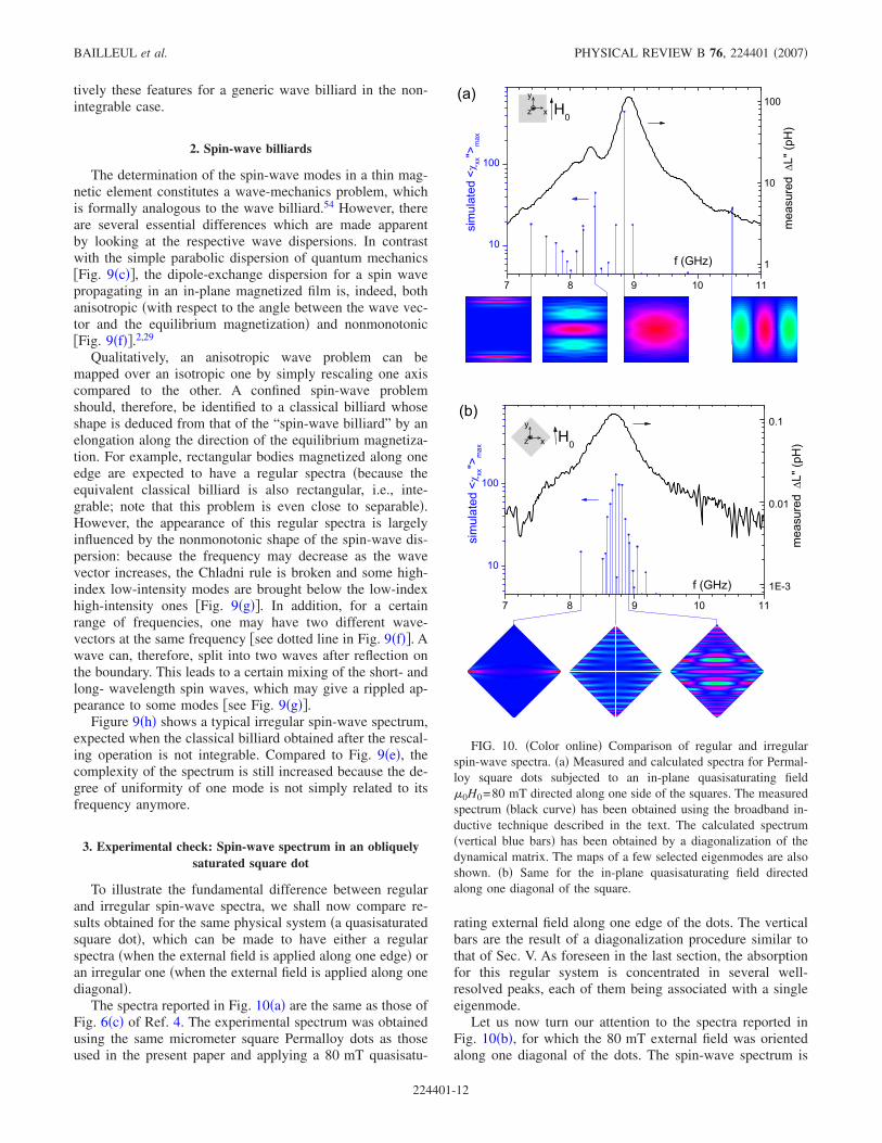
3. Experimental check: Spin-wave spectrum in an obliquelysaturated square dot
To illustrate the fundamental difference between regularand irregular spin-wave spectra, we shall now compare re-sults obtained for the same physical system �a quasisaturatedsquare dot�, which can be made to have either a regularspectra �when the external field is applied along one edge� oran irregular one �when the external field is applied along onediagonal�.
The spectra reported in Fig. 10�a� are the same as those ofFig. 6�c� of Ref. 4. The experimental spectrum was obtainedusing the same micrometer square Permalloy dots as thoseused in the present paper and applying a 80 mT quasisatu-
rating external field along one edge of the dots. The verticalbars are the result of a diagonalization procedure similar tothat of Sec. V. As foreseen in the last section, the absorptionfor this regular system is concentrated in several well-resolved peaks, each of them being associated with a singleeigenmode.
Let us now turn our attention to the spectra reported inFig. 10�b�, for which the 80 mT external field was orientedalong one diagonal of the dots. The spin-wave spectrum is
FIG. 10. �Color online� Comparison of regular and irregularspin-wave spectra. �a� Measured and calculated spectra for Permal-loy square dots subjected to an in-plane quasisaturating field�0H0=80 mT directed along one side of the squares. The measuredspectrum �black curve� has been obtained using the broadband in-ductive technique described in the text. The calculated spectrum�vertical blue bars� has been obtained by a diagonalization of thedynamical matrix. The maps of a few selected eigenmodes are alsoshown. �b� Same for the in-plane quasisaturating field directedalong one diagonal of the square.
BAILLEUL et al. PHYSICAL REVIEW B 76, 224401 �2007�
224401-12
now expected to be irregular: after elongation along one ofits diagonal, a square becomes, indeed, a flat rhombus, andrhombus billiards are generally not integrable. Indeed, themeasured absorption �see black line in Fig. 10�b�� is some-how spread over a single wide peak. The diagonalization �seevertical bars in Fig. 10�b�� shows that this peak consists ofseveral modes whose frequency spacing is smaller than theintrinsic linewidth of the Permalloy film, so that they cannotbe resolved experimentally. It should be noted that these re-sults are in good agreement with those of Barman et al.,55
who measured the transient magnetization distribution in asquare dot and observed a much more irregular behaviorwhen the field was applied along the diagonal of the square.In a similar way, the domain mode spectra studied in thispaper belong to the class of irregular spectra. Indeed, thedomains of the Landau configuration have the shape ofisorectangle triangles. After elongation along the direction ofthe equilibrium magnetization, these triangles become ge-neric isosceles ones, and classical billiards with generic tri-angular shape are not integrable.
To conclude, let us summarize the mechanisms respon-sible for the relatively featureless spin-wave spectra obtained
for saturated bodies with generic polygonal shapes: Genericpolygonal geometries are ergodic, so that the motion ex-plores the whole isofrequency line in the wave-vector space.Due to the complex anisotropic and nonmonotonic shape ofthe dipole-exchange dispersion, this isofrequency line cov-ers, in general, a wide range of wave vectors, from very longto very short wavelengths. As a consequence, the modes can-not be described by well-defined quantization wave vectors�except the lowest frequency mode which lies at the mini-mum of the spin-wave dispersion�. In particular, one cannotdefine a quasiuniform mode, because the longest wavelengthspin wave is continuously scattered over all the degeneratespin waves. Indeed, the main absorption peak for a uniformexcitation is composed of several modes whose y profilesdisplay both a slowly varying background and a fast oscil-lating component �see the 4.7, 5.1, and 5.4 GHz maps in Fig.4 or the 8.7 and 8.9 GHz maps in Fig. 10�b��. This is incontrast with, e.g., rectangular bodies magnetized along oneside, for which the reflections on the sides give only accessto a small number of wave-vector values �integrable dynam-ics�, so that a well-defined quantization wave vector can beassigned to each mode.
*[email protected] B. Hillebrands, K. Ounadjela, and A. E. Thiaville, Spin Dynamics
in Confined Magnetic Structures �Springer, Berlin, 2001�, Vol. 1;ibid. �Springer, Berlin, c1 c1a c1b c1cibid. �Springer, Berlin,
2 B. A. Kalinikos and A. N. Slavin, ibid. 19, 7013 �1986�.3 M. Buess, T. P. J. Knowles, R. Höllinger, T. Haug, U. Krey, D.
Weiss, D. Pescia, M. R. Scheinfein, and C. H. Back, Phys. Rev.B 71, 104415 �2005�.
4 M. Bailleul, R. Höllinger, and C. Fermon, Phys. Rev. B 73,104424 �2006�.
5 L. Giovannini, F. Montoncello, F. Nizzoli, G. Gubbiotti, G. Car-lotti, T. Okuno, T. Shinjo, and M. Grimsditch, Phys. Rev. B 70,172404 �2004�.
6 G. Gubbiotti, G. Carlotti, T. Okuno, M. Grimsditch, L. Giovan-nini, F. Montoncello, and F. Nizzoli, Phys. Rev. B 72, 184419�2005�.
7 K. E. Buchanan, P. E. Roy, M. Grimsditch, F. Y. Fradin, K. Y.Guslienko, S. D. Bader, and V. Novosad, Nat. Phys. 1, 172�2005�.
8 I. Neudecker, K. Perzlmaier, F. Hoffmann, G. Woltersdorf, M.Buess, D. Weiss, and C. H. Back, Phys. Rev. B 73, 134426�2006�.
9 R. Hertel, W. Wulfhekel, and J. Kirschner, Phys. Rev. Lett. 93,257202 �2004�.
10 C. Bayer, H. Schultheiss, B. Hillebrands, and R. L. Stamps, IEEETrans. Magn. 41, 3094 �2005�.
11 J. P. Park, P. Eames, D. M. Engebretson, J. Berezovsky, and P. A.Crowell, Phys. Rev. B 67, 020403�R� �2003�.
12 S. B. Choe, Y. Acremann, A. Scholl, A. Bauer, A. Doran, J. Stöhr,and H. A. Padmore, Science 304, 420 �2004�.
13 H. Stoll, A. Puzic, B. van Waeyenberge, P. Fisher, J. Raabe, M.Buess, T. Haug, R. Höllinger, C. Back, D. Weiss, and G. Den-beaux, Appl. Phys. Lett. 84, 3328 �2004�.
14 K. Perzlmaier, M. Buess, C. H. Back, V. E. Demidov, B. Hill-
ebrands, and S. O. Demokritov, Phys. Rev. Lett. 94, 057202�2005�.
15 J. Raabe, C. Quitmann, C. H. Back, F. Nolting, S. Johnson, and C.Buehler, Phys. Rev. Lett. 94, 217204 �2005�.
16 A. Krasyuk, F. Wegelin, S. A. Nepijko, H. J. Elmers, G. Schon-hense, M. Bolte, and C. M. Schneider, Phys. Rev. Lett. 95,207201 �2005�.
17 M. Buess, J. Raabe, K. Perzlmaier, C. H. Back, and C. Quitmann,Phys. Rev. B 74, 100404�R� �2006�.
18 K. W. Chou, A. Puzic, H. Stoll, D. Dolgos, G. Schtz, B. VanWaeyenberge, A. Vansteenkiste, T. Tyliszczak, G. Woltersdorf,and C. H. Back, Appl. Phys. Lett. 90, 202505 �2007�.
19 The Landau configuration comprises four domains separated byfour 90° domain walls and one vortex. It is the most stableremanent state for large enough square element.
20 C. Vaast-Paci and L. Leylekian, J. Magn. Magn. Mater. 237, 342�2001�.
21 M. Yan, G. Leaf, H. Kaper, R. Camley, and M. Grimsditch, Phys.Rev. B 73, 014425 �2006�.
22 M. Bolte, G. Meier, and C. Bayer, Phys. Rev. B 73, 052406�2006�.
23 A. Kaya and A. J. Bain, J. Appl. Phys. 99, 08B708 �2006�.24 K. Rivkin and J. B. Ketterson, J. Magn. Magn. Mater. 306, 204
�2006�.25 In this case, the reference data had been taken in a field of 45 mT
applied perpendicular to the axis of the coplanar waveguide,which also sets the magnetic history of the sample. Measure-ments in the quasisaturated state have shown that the absorptionis very low for this direction of the field �Ref. 4�, which ensuresthat our reference is a correct one.
26 http://llgmicro.home.mindspring.com27 Note also that the vortex translation mode does not appear in Fig.
2. This is because its frequency is far below the range investi-
MICROWAVE SPECTRUM OF SQUARE PERMALLOY DOTS:… PHYSICAL REVIEW B 76, 224401 �2007�
224401-13
gated here �it is expected in the 100 MHz range for the dimen-sions of our dots �Ref. 56��.
28 More precisely, the total absorption at frequency f can be writtenas a sum over all normal modes �Ref. 24�, each normal modebeing weighted by a factor containing the Lorentzian 1 / ��f− fn�2+�fn
2�, where fn and �fn are respectively the frequency andlinewidth of mode n �see, e.g., Appendix B of Ref. 4 for aderivation of this factor�.
29 R. W. Damon and J. R. Eshbach, J. Phys. Chem. Solids 19, 308�1961�.
30 A. Hubert and R. Schäfer, Magnetic Domains �Springer, Berlin,1998�.
31 H. Riedel and A. Seeger, Phys. Status Solidi B 46, 377 �1971�.32 J. Jorzick, S. O. Demokritov, B. Hillebrands, M. Bailleul, C. Fer-
mon, K. Y. Guslienko, A. N. Slavin, D. V. Berkov, and N. L.Gorn, Phys. Rev. Lett. 88, 047204 �2002�.
33 A. P. Malozemoff and J. C. Slonczewski, Magnetic Domain Wallsin Bubble Materials �Academic, New York, 1979�.
34 M. Ramesh and P. E. Wigen, J. Magn. Magn. Mater. 74, 123�1988�.
35 The vortex is assumed to be dynamically “dead” for the range offrequencies investigated here �Ref. 56�.
36 M. Sparks, Phys. Rev. B 1, 3831 �1970�.37 K. Y. Guslienko and A. N. Slavin, J. Magn. Magn. Mater. 215-
216, 576 �2000�.38 R. Zivieri and R. L. Stamps, Phys. Rev. B 73, 144422 �2006�.39 We also performed a full spin-wave calculation �not shown�,
which describes how the Hequ profile shown in Fig. 3�b� gener-ates localized spin-wave modes and how the dipole-exchangeequilibrium and dynamic fields combine to set the mode fre-quencies. This calculation basically confirms the result of themuch simpler domain-wall resonance approach. In addition, itindicates that the Hequ well is not deep enough to admit a secondbound state. �Such a mode would have one nodal line along thewall core, thus corresponding to a “breathing” of the domain-wall core.�
40 The assumption of a uniform equilibrium magnetization distribu-tion is quite a crude one, but we believe that the conclusions ofthis study are robust because the modes obtained are mostlylocated in the saturated interior part of the domain, so they arenot expected to be strongly influenced by the exact equilibriummagnetic configuration at the edges.
41 In all the diagonalization and variational calculations relative todomain modes, we assume hz=−mz �which corresponds to thelong-wavelength hypothesis of Appendix A in Ref. 4�. This isjustified by the fact that the spin-wave dispersions are onlyweakly affected by this assumption when the equilibrium field islow enough. This simplification allows one to restrict the diago-nalization to one block of the full dynamical matrix �block Dx in
Eq. �12� of Ref. 4�. As this block is symmetrical, one can use aquite efficient symmetrical matrix diagonalization routine. Wealso neglect in our calculations the equilibrium field Hequ. In-deed, Hequ is low and quite uniform except in the domain-wallcore �see Fig. 3�b��. Taking it into account would result in aslight negative shift for all mode frequencies.
42 W. H. Press, S. A. Teukolsky, W. T. Vetterling, and B. P. Flannery,Numerical Recipes in C �Cambridge University Press, Cam-bridge, England, 1992�.
43 K. Y. Guslienko and A. N. Slavin, Phys. Rev. B 72, 014463�2005�.
44 R. Courant and D. Hilbert, Methods of Mathematical Physics �In-terscience, New York, 1953�, Vol. 1.
45 Note that the functions of Eq. �6� would actually be true eigen-modes for the quantized wave problem if the wave dispersionwere isotropic �the isorectangle triangular classical billiard isknown to be integrable �Ref. 51��. This is not true for any an-isotropic wave dispersion, because the two terms of Eq. �6� nowcorrespond to different angles for the quantization wave vectors.
46 R. S. Knox and A. Gold, Symmetry in the Solid State �Benjamin,New York, 1964�.
47 C4� is the relevant symmetry group in our case because we ne-glect the vortex �Ref. 21�.
48 We also performed a full diagonalization calculation in this ge-ometry �not shown�. This confirmed the role of the symmetry indetermining the edge behavior of the modes. In particular, wecould reproduce the dipolar attraction effect mentioned abovefor E-type modes.
49 Object Oriented Micro Magnetic Framework, www.nist.gov50 R. Schäfer and A. DeSimone, IEEE Trans. Magn. 38, 2391
�2002�.51 M. Berry, in Chaotic Behaviour of Deterministic Systems, edited
by G. Iooss, R. H. G. Helleman, and R. Stora �North Holland,Amsterdam, 1983�, pp. 171–272.
52 V. I. Arnol’d, Mathematicals Methods of Classical Mechanics�Springer, New York, 1978�.
53 M. G. Gutzwiller, Chaos in Classical and Quantum Mechanics�Springer, New York, 1990�.
54 In this appendix , we do not discuss the influence of the long-range character of the dipolar interaction nor that of the stronglyinhomogeneous magnetic configurations. For the global descrip-tion of the spectrum of a quasisaturated magnetic body, we be-lieve that the most relevant properties of the dipole-exchangeoperator are included in the spin-wave dispersion.
55 A. Barman, V. V. Kruglyak, R. J. Hicken, J. M. Rowe, A. Kun-drotaite, J. Scott, and M. Rahman, Phys. Rev. B 69, 174426�2004�.
56 K. Y. Guslienko, X. F. Han, D. J. Keavney, R. Divan, and S. D.Bader, Phys. Rev. Lett. 96, 067205 �2006�.
BAILLEUL et al. PHYSICAL REVIEW B 76, 224401 �2007�
224401-14