Embed Size (px)
Citation preview
Le marquage CE qui se trouve sur ce produit indique que celui-ci est en conformité avec la directive européenne des dispositifs médicaux 93/42/CEEThis product bears a CE marking in accordance with the provisions of the 93/42/EEC MDD dated June 14, 1993.0459
Technical PublicationOM-0269R5
Operation
Movix 4.0 E+Portable X-ray Units
STEPHANIX
10 rue Jean Moulin, Z.I. du Bayon
42150 LA RICAMARIE
FRANCE
Tel : 00 33 4 77 47 81 60
Fax : 00 33 4 77 37 55 19

¡ IMPORTANTE ! ... Protección ante los rayos-X
LOS EQUIPOS DE RAYOS-X SON PELIGROSOS PARA EL PACIENTE Y EL OPERADORA MENOS QUE LAS MEDIDAS DE PROTECCION SEAN ESTRICTAMENTE OBSERVADAS
Si el equipo de rayos-X no se usa adecuadamente, puede causar lesiones. Por este motivo, las instruccionesaquí incluidas se deben leer y comprender en su totalidad antes de intentar poner el equipo en funcionamiento.Estaremos gustosos de asistir y cooperar en poner el equipo en marcha.
Aunque el equipo está construido según las normas de seguridad más estrictas y presenta un alto grado de protección contra lasradiaciones-X, ningún diseño practico puede ofrecer una protección completa. Tampoco ningún diseño practico puede obligar al operadora tomar las precauciones adecuadas para prevenir la posibilidad de que cualquier persona de manera descuidada, poco sensata oignorante, se exponga a radiaciones directas o indirectas.
Es importante que cualquier persona relacionada con radiaciones-X esté debidamente entrenada y tome las medidas adecuadas paraasegurar la protección contra posibles lesiones.
El fabricante asume que todo operador y personal de servicio autorizado para manejar, instalar, calibrar o mantener este equipo, esconsciente del peligro que conlleva la exposición excesiva a las radiaciones-X, está suficientemente entrenado y posee los conocimientonecesarios para ello. Por lo tanto, el equipo aquí descrito se vende entendiendo que el fabricante, sus agentes y representantesno tienen ninguna responsabilidad en caso de lesiones o daños que puedan resultar de la exposición a dichas radiaciones.
Existen diversos materiales y dispositivos protectores, cuyo uso es recomendable.
IMPORTANT ! ... X-ray Protection
X-RAY EQUIPMENT IS DANGEROUS TO BOTH PATIENT AND OPERATORUNLESS MEASURES OF PROTECTION ARE STRICTLY OBSERVED
X-ray equipment if not properly used may cause injury. Accordingly, the instructions herein should be thoroughlyread and understood before attempting to place this equipment in operation. We will be glad to assist andcooperate in placing this equipment in use.
Although this apparatus is built to the highest safety standards and incorporates a high degree of protection against X-radiation otherthan the useful beam, no practical design of equipment can provide complete protection. Nor can any practical design compel theoperator to take adequate precautions to prevent the possibility of any persons carelessly, unwisely, or unknowingly exposing themselvesor others to X-radiation.
It is important that everyone working with X-radiation be properly trained and take adequate steps to insure protection against injury.
The manufacturer assumes that all operator and service personnel authorized to use, install, calibrate and maintain this equipmentis cognizant of the danger of excessive exposure to X-radiation, is sufficiently trained and has the required knowledges for it. Theequipment herein described is sold with the understanding that the manufacturer, its agents, and representatives are not liable forinjury or damage which may result from exposure to X-radiation.
Various protective material and devices are available. It is recommended that such materials and devices be used.
IMPORTANT ! ... Protection contre les rayons-X
L’EQUIPEMENT RAYONS-X EST DANGEREUX A LA FOIS POUR LE PATIENT ET POUR L’OPERATEURA MOINS D’OBSERVER STRICTEMENT LES CONSIGNES DE PROTECTION
L’équipement à rayons-X peut provoquer des blessures s’il n’est pas correctement utilisé. En conséquence,les instructions de ce manuel doivent être lues attentivement et bien assimilées avant de tenter de mettre enroute ce matériel. Nous serons heureux de vous assister et de coopérer à l’installation de ce matériel.
Bien que cet équipement soit construit selon les normes de construction les plus sévères et qu’il comporte un haut degré de protectioncontre le rayonnement-X en dehors du rayon utile, aucune conception n’apporte une protection totale. De même qu’aucune conceptionne peut obliger l’opérateur à prendre les précautions adéquates afin d’éviter que toute personne ne s’expose ou n’expose les autresau rayonnement sans précaution, de façon imprudente et inconsciente.
Il est important que toutes les personnes travaillant avec le rayonnement-X soit correctement formées et prennent les mesures adéquatesafin de se protéger contre toute blessure.
Le constructeur suppose que tous les utilisateurs et le personnel d’entretien autorisé à utiliser, installer, calibrer et entretenir cet équipementest conscient du danger de l’exposition excessive au rayonnement-X, est suffisamment formé et possède les connaissances nécessairespour cela. L’équipement décrit dans le présent manuel est vendu sous réserve que le fabricant, ses agents et représentants ne soientpas tenus pour responsables des blessures ou dommages qui pourraient résulter d’une exposition aux rayons-X.
Plusieurs matériels de protection et systèmes sont disponibles. L’utilisation de ces matériels et systèmes de protection est recommandée.
DECLARACION AMBIENTALSOBRE LA VIDA UTIL DEL EQUIPO O SISTEMA
Este equipo o sistema contiene componentes y materiales peligrosos para el medioambiente (talescomo tarjetas de circuito impreso, componentes electrónicos, aceite dieléctrico usado, plomo,baterías, etc), los cuales se consideran y son residuos peligrosos al finalizar la vida útil del equipo osistema, según establecen las normas internacionales, nacionales y locales.
El fabricante recomienda que al finalizar la vida útil de equipo o sistema, se contacte con unrepresentante autorizadodel fabricante o con ungestor autorizadode residuos para la retirada deesteequipo o sistema.
ENVIRONMENTAL STATEMENTON THE LIFE CYCLE OF THE EQUIPMENT OR SYSTEM
This equipment or system contains environmentally dangerous components and materials (such asPCB‘s, electronic components, used dielectric oil, lead, batteries etc.) which, once the life-cycle of theequipment or system comes to an end, becomes dangerous and need to be considered as harmfulwaste according to the international, domestic and local regulations.
The manufacturer recommends to contact an authorized representative of the manufacturer or anauthorized waste management company once the life-cycle of the equipment or system comes to anend to remove this equipment or system.
DECLARATION D’ENVIRONNEMENTSUR LA VIE UTILE DE L’EQUIPEMENT OU SYSTEME
Cet équipement ou système contient des composants et matériaux dangereux pour l’environnement(ex: électroniques cartes, composants électroniques, huile diélectrique usée, plomb, batteries, etc.),lesquels sont considérés comme résidus dangereux en cycle terminal de vie d’un équipement ousystème, en accord avec les normes internationales, nationales et locales en vigueur.
Le fabricant recommande une fois le cycle terminal de l’équipement ou système atteint, de contacterun représentant autorisé du fabricant ou les autorités compétentes en la matière afin d’organiser etde gérer le recyclage adéquat de cet équipement ou appareil.
Portable X-Ray Units
Operation
OM-0269R5
REVISION HISTORY
REVISION DATE REASON FOR CHANGE
0 JAN 29, 2004 First edition.
1 APR 1, 2004 UL Classified, Automatic Power Line Detection.
2 JUNE 1, 2004 IEC declaration and dimensions.
3 SEP 10, 2004 Error Code “E50”
4 APR 18, 2005 Duty Cycle update
5 OCT 27, 2005 Technical Specifications
This Document is the English original version, edited and supplied by the manufacturer.
The Revision state of this Document is indicated in the code number shown at the bottom of this page.
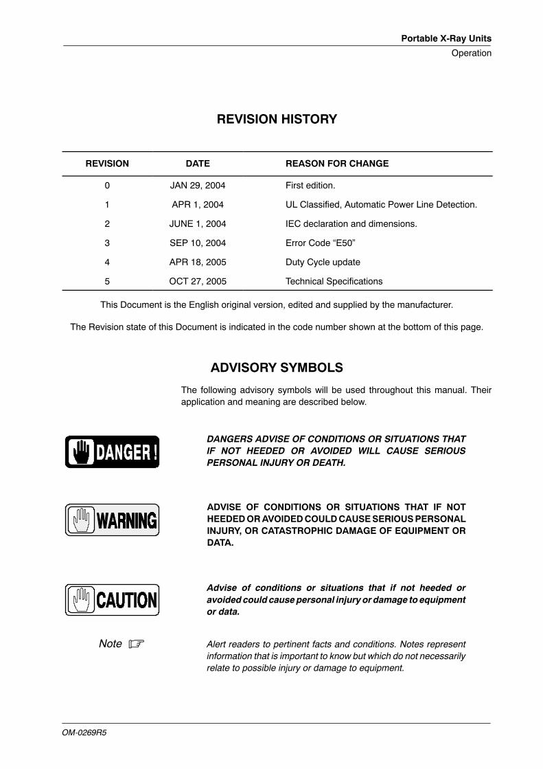
ADVISORY SYMBOLS
The following advisory symbols will be used throughout this manual. Theirapplication and meaning are described below.
DANGERS ADVISE OF CONDITIONS OR SITUATIONS THATIF NOT HEEDED OR AVOIDED WILL CAUSE SERIOUSPERSONAL INJURY OR DEATH.
ADVISE OF CONDITIONS OR SITUATIONS THAT IF NOTHEEDEDORAVOIDEDCOULDCAUSESERIOUSPERSONALINJURY, OR CATASTROPHIC DAMAGE OF EQUIPMENT ORDATA.
Advise of conditions or situations that if not heeded oravoidedcould causepersonal injury or damage to equipmentor data.
Note . Alert readers to pertinent facts and conditions. Notes representinformation that is important to know but which do not necessarilyrelate to possible injury or damage to equipment.
Portable X-Ray Units
Operation
OM-0269R5
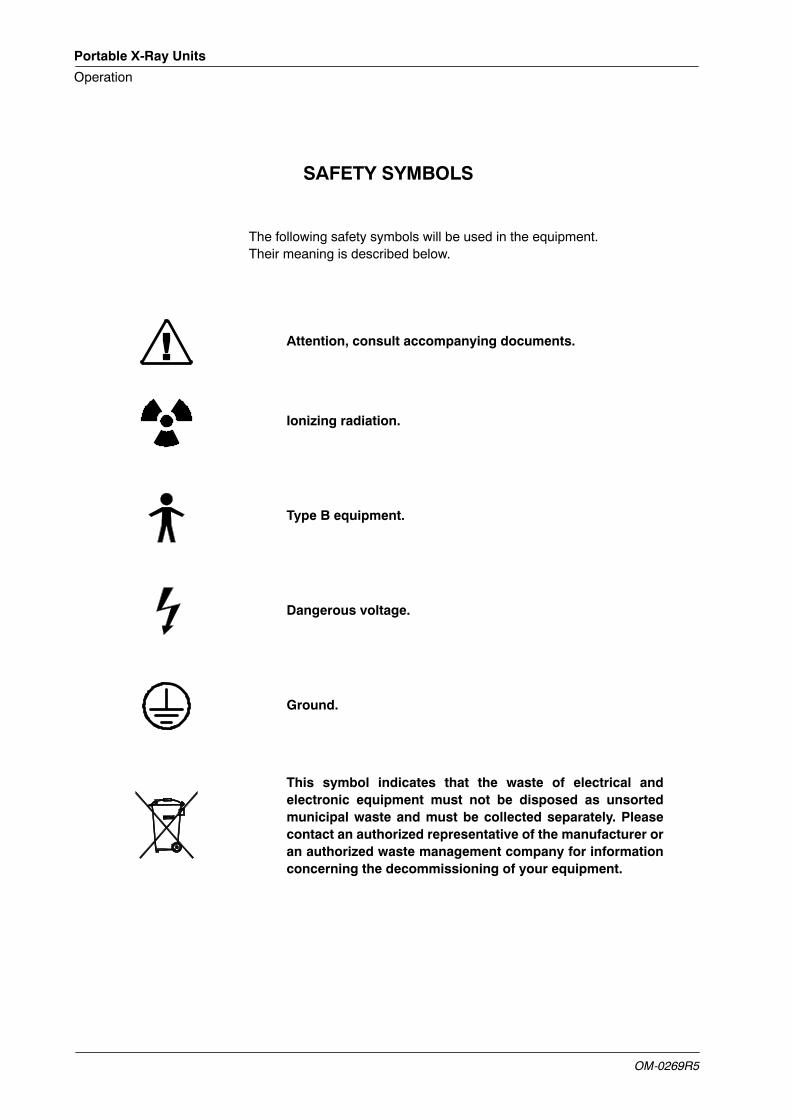
SAFETY SYMBOLS
The following safety symbols will be used in the equipment.Their meaning is described below.
Attention, consult accompanying documents.
Ionizing radiation.
Type B equipment.
Dangerous voltage.
Ground.
This symbol indicates that the waste of electrical andelectronic equipment must not be disposed as unsortedmunicipal waste and must be collected separately. Pleasecontact an authorized representative of the manufacturer oran authorized waste management company for informationconcerning the decommissioning of your equipment.
Portable X-Ray Units
Operation
OM-0269R5 i
TABLE OF CONTENTS
Section Page
1 INTRODUCTION 1. . . . . . . . . . . . . . . . . . . . . . . . . . . . . . . . . . . . . . . . . . . . . . . . . . . . . . . . .
1.1 General Features 2. . . . . . . . . . . . . . . . . . . . . . . . . . . . . . . . . . . . . . . . . . . . . . . . . . .
1.2 Product Identification 3. . . . . . . . . . . . . . . . . . . . . . . . . . . . . . . . . . . . . . . . . . . . . . . .
1.3 Certifications 4. . . . . . . . . . . . . . . . . . . . . . . . . . . . . . . . . . . . . . . . . . . . . . . . . . . . . . .
1.4 Classification 4. . . . . . . . . . . . . . . . . . . . . . . . . . . . . . . . . . . . . . . . . . . . . . . . . . . . . . .
2 SAFETY 5. . . . . . . . . . . . . . . . . . . . . . . . . . . . . . . . . . . . . . . . . . . . . . . . . . . . . . . . . . . . . . . .
2.1 General 5. . . . . . . . . . . . . . . . . . . . . . . . . . . . . . . . . . . . . . . . . . . . . . . . . . . . . . . . . . .
2.2 Responsibilities 6. . . . . . . . . . . . . . . . . . . . . . . . . . . . . . . . . . . . . . . . . . . . . . . . . . . . .
2.3 Maximum Permissible Dose (MPD) 8. . . . . . . . . . . . . . . . . . . . . . . . . . . . . . . . . . .
2.4 Radiation Protection 8. . . . . . . . . . . . . . . . . . . . . . . . . . . . . . . . . . . . . . . . . . . . . . . .
2.5 Monitoring of Personnel 9. . . . . . . . . . . . . . . . . . . . . . . . . . . . . . . . . . . . . . . . . . . . .
2.6 Protection against Electric Shock Hazards 9. . . . . . . . . . . . . . . . . . . . . . . . . . . . .
2.7 Protection against Hazards from Unwanted or Excessive Radiation 10. . . . . . . .
2.8 Designated Significant zones of Occupancy 10. . . . . . . . . . . . . . . . . . . . . . . . . . . .
3 OPERATING CONTROLS 13. . . . . . . . . . . . . . . . . . . . . . . . . . . . . . . . . . . . . . . . . . . . . . . . .
3.1 Mobile Unit 15. . . . . . . . . . . . . . . . . . . . . . . . . . . . . . . . . . . . . . . . . . . . . . . . . . . . . . . .
3.1.1 Parking Position of the Arm 16. . . . . . . . . . . . . . . . . . . . . . . . . . . . . . . . . . . .
3.1.2 Unfolding the Unit 17. . . . . . . . . . . . . . . . . . . . . . . . . . . . . . . . . . . . . . . . . . . .
3.1.3 Folding the Unit 18. . . . . . . . . . . . . . . . . . . . . . . . . . . . . . . . . . . . . . . . . . . . . .
3.2 X-Ray Unit 19. . . . . . . . . . . . . . . . . . . . . . . . . . . . . . . . . . . . . . . . . . . . . . . . . . . . . . . .
3.2.1 Power ON / OFF 19. . . . . . . . . . . . . . . . . . . . . . . . . . . . . . . . . . . . . . . . . . . . .
3.2.2 Automatic Power Line Detection System 20. . . . . . . . . . . . . . . . . . . . . . . .
3.2.3 Manual Power Reduction 21. . . . . . . . . . . . . . . . . . . . . . . . . . . . . . . . . . . . .
3.2.4 Control Panel 22. . . . . . . . . . . . . . . . . . . . . . . . . . . . . . . . . . . . . . . . . . . . . . . .
3.2.4.1 Focal Spot Indicators 22. . . . . . . . . . . . . . . . . . . . . . . . . . . . . . . . .
3.2.4.2 Radiographic Parameters 23. . . . . . . . . . . . . . . . . . . . . . . . . . . . .
3.2.4.3 Exposure Controls 25. . . . . . . . . . . . . . . . . . . . . . . . . . . . . . . . . . .
Portable X-Ray Units
Operation
OM-0269R5ii
Section Page
3.3 Collimator 26. . . . . . . . . . . . . . . . . . . . . . . . . . . . . . . . . . . . . . . . . . . . . . . . . . . . . . . . .
3.4 X-ray Handswitch 28. . . . . . . . . . . . . . . . . . . . . . . . . . . . . . . . . . . . . . . . . . . . . . . . . . .
3.5 Heat Units and Temperature of Power Module 28. . . . . . . . . . . . . . . . . . . . . . . . . .
3.6 Error Codes 29. . . . . . . . . . . . . . . . . . . . . . . . . . . . . . . . . . . . . . . . . . . . . . . . . . . . . . . .
4 OPERATING SEQUENCES 31. . . . . . . . . . . . . . . . . . . . . . . . . . . . . . . . . . . . . . . . . . . . . . .
4.1 Start-up Routine 31. . . . . . . . . . . . . . . . . . . . . . . . . . . . . . . . . . . . . . . . . . . . . . . . . . . .
4.2 X-ray Tube Seasoning and X-ray Tube Warm-up 31. . . . . . . . . . . . . . . . . . . . . . .
4.2.1 Seasoning Procedure 32. . . . . . . . . . . . . . . . . . . . . . . . . . . . . . . . . . . . . . . .
4.2.2 Warming-up Procedure 32. . . . . . . . . . . . . . . . . . . . . . . . . . . . . . . . . . . . . . .
4.3 Radiographic Operation 33. . . . . . . . . . . . . . . . . . . . . . . . . . . . . . . . . . . . . . . . . . . . .
5 PERIODIC MAINTENANCE 35. . . . . . . . . . . . . . . . . . . . . . . . . . . . . . . . . . . . . . . . . . . . . . .
5.1 Operator Tasks 35. . . . . . . . . . . . . . . . . . . . . . . . . . . . . . . . . . . . . . . . . . . . . . . . . . . . .
5.2 Service Tasks 36. . . . . . . . . . . . . . . . . . . . . . . . . . . . . . . . . . . . . . . . . . . . . . . . . . . . . .
6 TECHNICAL SPECIFICATIONS 37. . . . . . . . . . . . . . . . . . . . . . . . . . . . . . . . . . . . . . . . . . .
Portable X-Ray Units
Operation
OM-0269R5 1
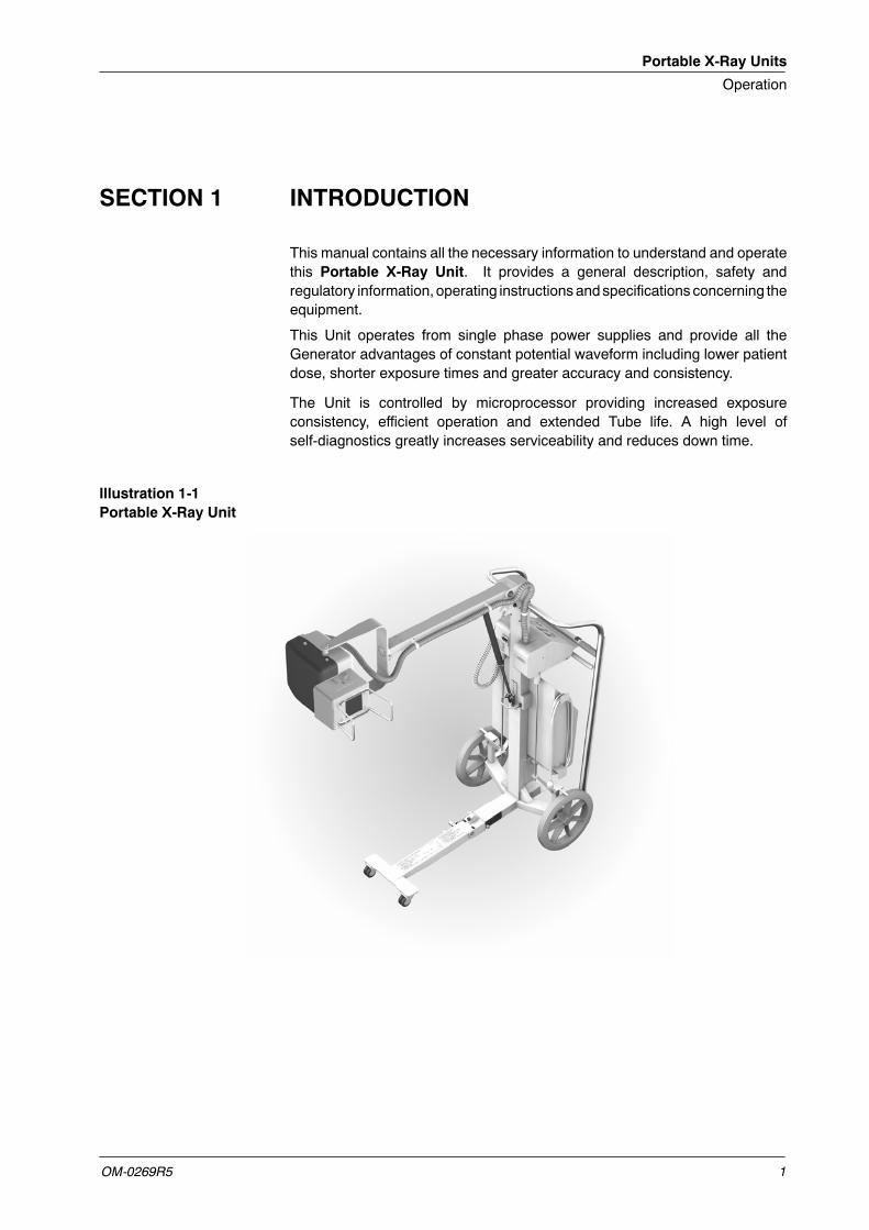
SECTION 1 INTRODUCTION
This manual contains all the necessary information to understand and operatethis Portable X-Ray Unit. It provides a general description, safety andregulatory information, operating instructions andspecifications concerning theequipment.
This Unit operates from single phase power supplies and provide all theGenerator advantages of constant potential waveform including lower patientdose, shorter exposure times and greater accuracy and consistency.
The Unit is controlled by microprocessor providing increased exposureconsistency, efficient operation and extended Tube life. A high level ofself-diagnostics greatly increases serviceability and reduces down time.
Illustration 1-1Portable X-Ray Unit
Portable X-Ray Units
Operation
OM-0269R52
All functions, displays and controls are logically arranged, are easily accessibleand identified to prevent confusion. Radiographic technique factors andfunctions are selected by touch sensitive push-buttons and displayed on theControl Panel.
The equipment consists of:
• Control Panel with controls and displays for radiographic operations.
• Handswitch.
• Power Module containing control and power components.
• HV Tank that comprises:
G High Voltage Transformer.
G Filament Transformer.
G X-ray Tube.
• Collimator with controls to limit the X-ray beam.
• SID Guard (optional).
• Mobile Unit with an Articulated Arm and a Cassettes Basket .
1.1 GENERAL FEATURES
The main features of this Portable X-Ray Unit are:
• Safe and easy operation.
• Constant potential high frequency operating on single phase lines.
• Two point control by selecting kVp and mAs.
• Tube protection circuitry prolongs Tube life and increases systemperformance.
• Equipped with closed loop control of X-Ray Tube current, kVp andfilaments, which minimize potential errors and the need forreadjustments.
• Standard electric outlet operation from 100 to 240¦10% VAC.
• Automatic line voltage compensation due to closed loop operation ofX-ray Tube current and kVp.
• Heat Unit storage for the X-ray Tube.
Portable X-Ray Units
Operation
OM-0269R5 3
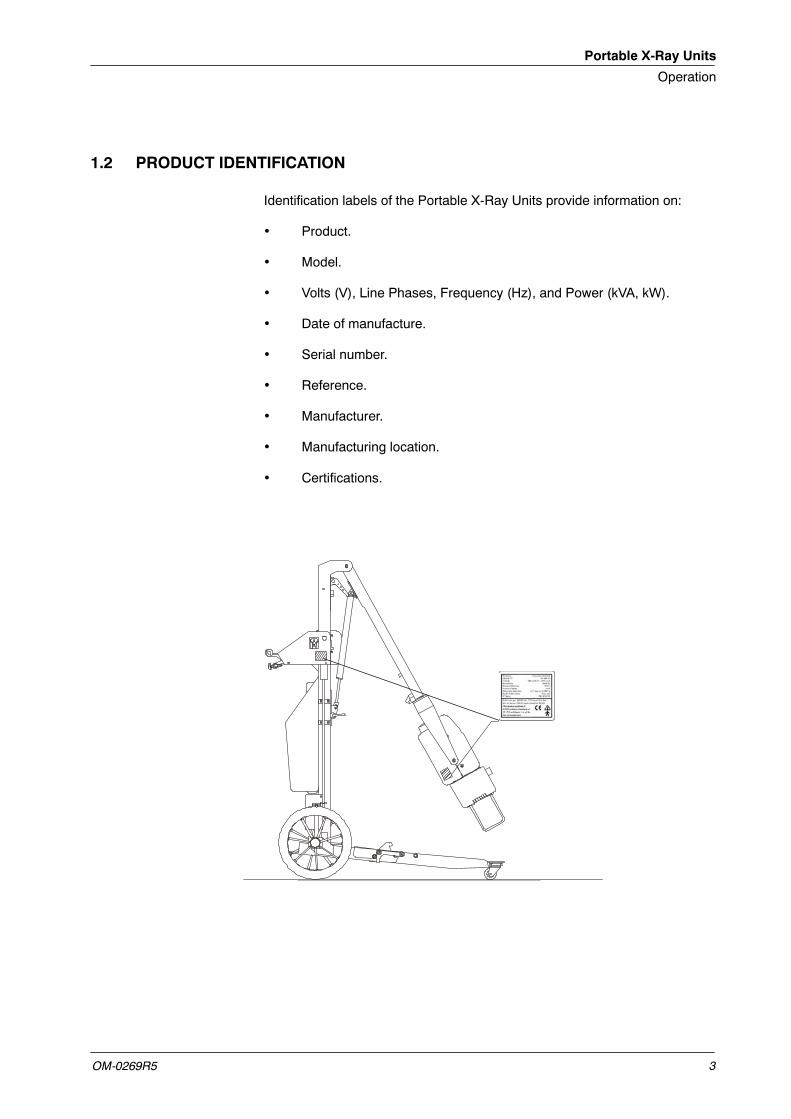
1.2 PRODUCT IDENTIFICATION
Identification labels of the Portable X-Ray Units provide information on:
• Product.
• Model.
• Volts (V), Line Phases, Frequency (Hz), and Power (kVA, kW).
• Date of manufacture.
• Serial number.
• Reference.
• Manufacturer.
• Manufacturing location.
• Certifications.
Portable X-Ray Units
Operation
OM-0269R54
1.3 CERTIFICATIONS
The X-ray Unit covered by this Operation Manual is authorized to be markedwith CE MARKING in accordance with the provisions of the Council Directive93 / 42 / EEC concerning Medical Devices.
1.4 CLASSIFICATION
The X-Ray Unit covered by this Operation Manual is classified as:
• Protection against Electric Shock: Class I -- Type B applied parts.
• Protection against Harmful Ingress of Water: Ordinary.
• Degree of Safety in the presence of Flammable Anesthetics Mixture withair or with oxygen or with nitrous oxide: Not suitable for use in thepresence of Flammable Anesthetics Mixture with air or with oxygen orwith nitrous oxide.
• Mode of Operation: Continuous with intermittent loading.
Portable X-Ray Units
Operation
OM-0269R5 5
SECTION 2 SAFETY
2.1 GENERAL
Keep this Operating Manual with the equipment at all times and periodicallyreview the Operating and Safety instructions.
For continue safe use of this equipment follow theinstructions in this Operating Manual. Study this manualcarefully before using the equipment and keep it at hand forquick reference.
THE EQUIPMENT DESCRIBED IN THIS MANUAL MUST BEONLY HANDLE BY QUALIFIED PERSONNEL PREVIOUSLYTRAINED IN IT.
X-RAYEQUIPMENT ISDANGEROUSTOBOTHPATIENT ANDOPERATOR UNLESS PROTECTION MEASURES ARESTRICTLY OBSERVED.
IT IS VITALLY IMPORTANT THAT EVERYONE ASSOCIATEDWITH X-RAY RADIATION IS FAMILIAR WITH THE SAFETYAND REGULATORY INSTRUCTIONS CONTAINED WITHINTHIS MANUAL, IN PARTICULAR, THE STATEMENT AT THEBEGINNING OF THIS MANUAL ENTITLED “IMPORTANT!...X-RAY PROTECTION”.
THESE INSTRUCTIONS SHOULD BE THOROUGHLY READAND UNDERSTOOD BEFORE ATTEMPTING TO PLACE THISEQUIPMENT IN OPERATION.
Although X-radiation can be hazardous, X-ray equipment does not pose anydanger when it is properly used. Please ensure that all service and operatingpersonnel are properly trained and informed on the hazards of radiation. Thoseresponsible for the system must understand the safety requirements for X-rayoperation. Please study this manual and the manuals for each systemcomponent to be fully aware of all the safety and operational requirements.
Portable X-Ray Units
Operation
OM-0269R56
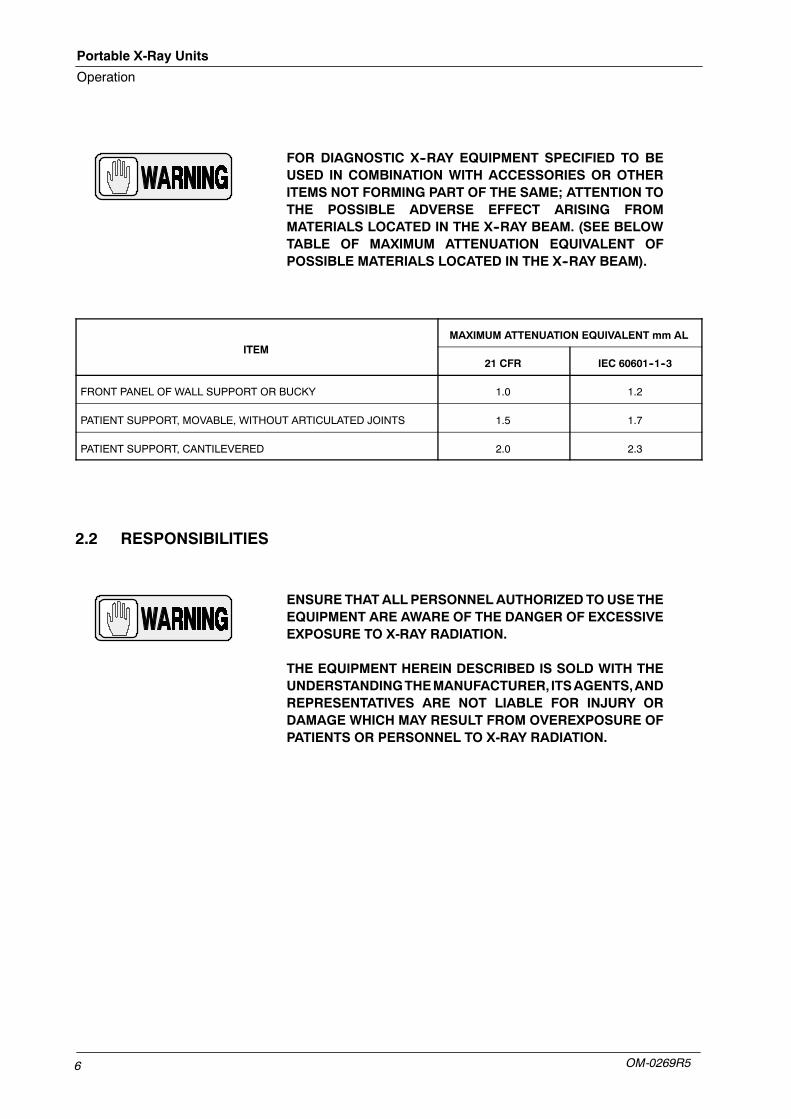
FOR DIAGNOSTIC X--RAY EQUIPMENT SPECIFIED TO BEUSED IN COMBINATION WITH ACCESSORIES OR OTHERITEMS NOT FORMING PART OF THE SAME; ATTENTION TOTHE POSSIBLE ADVERSE EFFECT ARISING FROMMATERIALS LOCATED IN THE X--RAY BEAM. (SEE BELOWTABLE OF MAXIMUM ATTENUATION EQUIVALENT OFPOSSIBLE MATERIALS LOCATED IN THE X--RAY BEAM).
ITEMMAXIMUM ATTENUATION EQUIVALENT mm AL
ITEM21 CFR IEC 60601--1--3
FRONT PANEL OF WALL SUPPORT OR BUCKY 1.0 1.2
PATIENT SUPPORT, MOVABLE, WITHOUT ARTICULATED JOINTS 1.5 1.7
PATIENT SUPPORT, CANTILEVERED 2.0 2.3
2.2 RESPONSIBILITIES
ENSURE THATALLPERSONNELAUTHORIZED TOUSETHEEQUIPMENT ARE AWARE OF THE DANGER OF EXCESSIVEEXPOSURE TO X-RAY RADIATION.
THE EQUIPMENT HEREIN DESCRIBED IS SOLD WITH THEUNDERSTANDINGTHEMANUFACTURER, ITSAGENTS,ANDREPRESENTATIVES ARE NOT LIABLE FOR INJURY ORDAMAGE WHICH MAY RESULT FROM OVEREXPOSURE OFPATIENTS OR PERSONNEL TO X-RAY RADIATION.
Portable X-Ray Units
Operation
OM-0269R5 7
THE MANUFACTURER DOES NOT ACCEPT ANYRESPONSIBILITY FOR OVEREXPOSURE OF PATIENTS ORPERSONNEL TO X-RAY RADIATION GENERATED BY THISEQUIPMENT WHICH IS A RESULT OF POOR OPERATINGTECHNIQUES OR PROCEDURES.
NO RESPONSIBILITY WILL BE ASSUMED FOR ANYEQUIPMENT THAT HAS NOT BEEN SERVICED ANDMAINTAINED INACCORDANCEWITHTHEMANUFACTURERINSTRUCTIONS, OR WHICH HAS BEEN MODIFIED ORTAMPERED WITH IN ANY WAY.
IT IS THERESPONSIBILITYOF THEOPERATOR TOENSURETHE SAFETY OF THE PATIENT WHILE THE X-RAYEQUIPMENT IS IN OPERATION BY VISUAL OBSERVATION,PROPERPATIENTPOSITIONING,ANDUSEOFTHEDEVICESTHAT ARE INTENDED TO PREVENT PATIENT INJURY.
ALWAYS WATCH ALL PARTS OF THE SYSTEM TO VERIFYTHAT THERE IS NO INTERFERENCE AND NO POSSIBILITYOF COLLISION WITH THE PATIENT OR WITH OTHEREQUIPMENTS.
MAKE SURE THAT THE X-RAY TUBE IS PLACED IN TOWORKING POSITION WITH THE REFERENCE AXIS (X-RAYBEAM) POINTING TO THE RECEPTION AREA.
SHOULD ANY INTERFERENCE (EMC) BE DETECTED WITHOTHER EQUIPMENT, PLEASE POSITION OTHEREQUIPMENT AWAY FROM THIS ONE.
Portable X-Ray Units
Operation
OM-0269R58
2.3 MAXIMUM PERMISSIBLE DOSE (MPD)
Before operation, persons qualified and authorized to operate this equipmentshould be familiar with the Recommendations of the International Commissionon Radiological Protection, contained in Annals Number 60 of the ICRP, withapplicable National Standards, and should have been trained in use of theequipment.
THE OPERATOR SHALL USE FOCAL SPOT TO SKINDISTANCES AS LARGE AS POSSIBLE IN ORDER TO KEEPTHE ABSORBED DOSE TO THE PATIENT AS LOW ASREASONABLY ACHIEVABLY.
2.4 RADIATION PROTECTION
Becauseexposure toX-ray radiationmaybedamaging tohealth, usegreat caretoprovideprotectionagainst exposure to theprimary beam. Someof theeffectsof X-ray radiation are cumulative and may extend over a period of months oryears. The best safety rule for X-ray operator is “Avoid exposure to the primarybeam at all times”.
Any object in the path of the primary beam produces secondary (scattered)radiation. The intensity of the secondary radiation is dependent upon theenergy and intensity of the primary beam and the atomic number for the objectmaterial struck by the primary beam. Secondary radiation may be of greaterintensity than that of the radiation reaching the film. Take protective measuresto safeguard against it.
An effective protective measure is the use of lead shielding. To minimizedangerous exposure, use such items as lead screens, lead impregnatedgloves, aprons, thyroid collars, etc. The lead screen should contain aminimumof 2.0 mm of lead or equivalent and personal protective devices (aprons,gloves, etc.) must contain a minimum of 0.25 mm of lead or equivalent. Forconfirmation of the local requirements at your site, please refer to your “LocalRadiation Protection Rules” as provided by your Radiation Protection Advisor.
WHILE OPERATING OR SERVICING X-RAY EQUIPMENT,ALWAYS KEEP A DISTANCE NOT LESS THAN 2 METERSFROM THE FOCAL SPOT AND X-RAY BEAM, PROTECTBODY AND DO NOT EXPOSE HANDS, WRISTS, ARMS OROTHER PARTS OF THE BODY TO THE PRIMARY BEAM.
Portable X-Ray Units
Operation
OM-0269R5 9
2.5 MONITORING OF PERSONNEL
Monitoring of personnel to determine theamount of radiation towhich theyhavebeen exposed provides a valuable cross check to determine whether or notsafety measures are adequate. It may reveal inadequate or improper radiationprotection practices and potentially serious radiation exposure situations.
Themost effectivemethod of determiningwhether or not the existing protectivemeasures are adequate is the use of instruments to measure the exposure.These measurements should be taken at all locations where the operator, orany portion of the body may be exposed. Exposure must never exceed theaccepted tolerable dose.
A frequently used, but less accurate, method of determining the amount ofexposure is the placement of film at strategic locations. After a specified periodof time, develop the film to determine the amount of radiation.
A common method of determining whether personnel have been exposed toexcessive radiation is the use of personal radiation dosimeters. These consistof X-ray sensitive film or thermoluminescent material enclosed within a holderthat may be worn on the body. Even though this device only measures theradiation which reaches the area of the body on which they are worn, they doprovide a reasonable indication of the amount of radiation received.
2.6 PROTECTION AGAINST ELECTRIC SHOCK HAZARDS
This X-ray Unit has been classified type-B ( ) in accordance with IEC 60601-1.
This equipment meets the following Safety Standards: IEC 60601-1,IEC 60601-1-1, IEC 60601-2-7.
ACCORDING TO MDD/93/42/CEE, THIS UNIT IS EQUIPPEDWITH EMC FILTERS. THE LACK OF THE PROPERGROUNDING MAY PRODUCE ELECTRICAL SHOCK TO THEUSER.
Portable X-Ray Units
Operation
OM-0269R510
2.7 PROTECTION AGAINST HAZARDS FROM UNWANTED OR EXCESSIVERADIATION
Statement of compliance: This X-ray Unit with radiation protection inaccordance with IEC 60601-1-3 for which compliance is to be stated.
This X-ray unit meets Standard IEC 60601-1-3 and IEC 60601-1-28requirements.
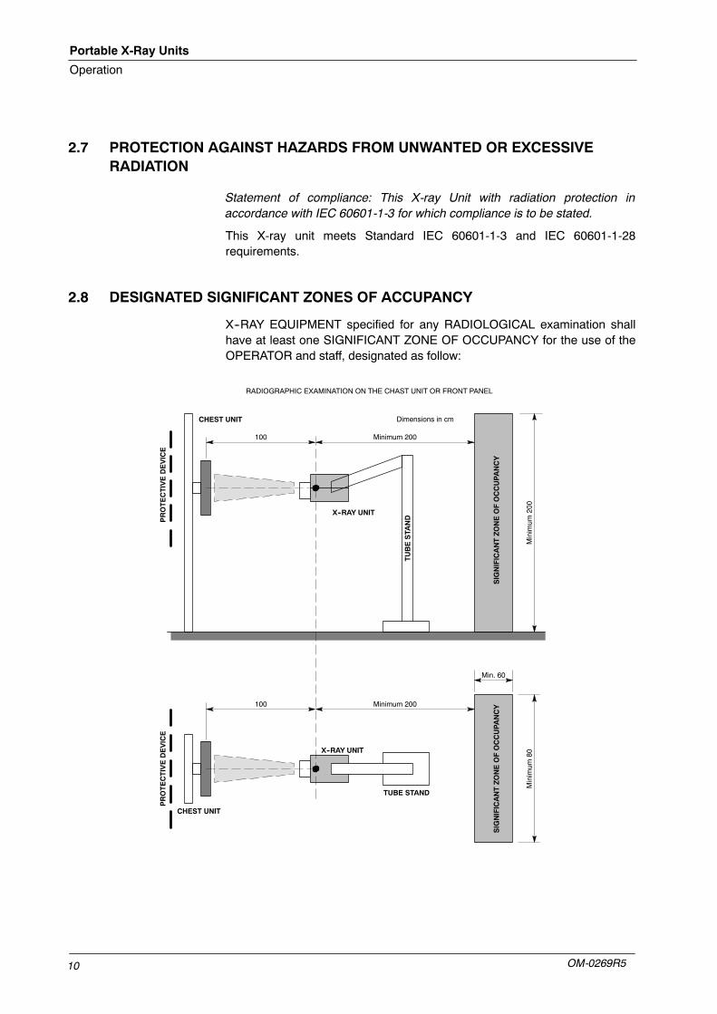
2.8 DESIGNATED SIGNIFICANT ZONES OF ACCUPANCY
X--RAY EQUIPMENT specified for any RADIOLOGICAL examination shallhave at least one SIGNIFICANT ZONE OF OCCUPANCY for the use of theOPERATOR and staff, designated as follow:
100 Minimum 200
Minimum
200
X--RAY UNIT
CHEST UNIT
SIGNIFICANTZONEOFOCCUPANCY
PROTECTIVEDEVICE
Dimensions in cm
100 Minimum 200
Minimum
80
X--RAY UNIT
CHEST UNIT
SIGNIFICANTZONEOFOCCUPANCY
PROTECTIVEDEVICE
Min. 60
TUBESTA
ND
TUBE STAND
RADIOGRAPHIC EXAMINATION ON THE CHAST UNIT OR FRONT PANEL

Portable X-Ray Units
Operation
OM-0269R5 11
100
Minimum 200
Minimum
200
TUBESTA
ND
SIGNIFICANTZONEOFOCCUPANCY
Dimensions in cm
EXAMINATION TABLE
X--RAY UNIT
Minimum 200SIGNIFICANTZONEOFOCCUPANCY
Minimum
200
Minimum 200
TUBE STAND
EXAMINATION TABLE
Minimum
80
SIGNIFICANTZONEOFOCCUPANCY
Min. 60
X--RAY UNIT
Minimum 200
Minimum
80
SIGNIFICANTZONEOFOCCUPANCY
Min. 60
Minimum 80
SIGNIFICANT ZONE OF OCCUPANCY
Min.60
Minimum
200
Minimum
200
Minimum 80
SIGNIFICANT ZONE OF OCCUPANCY
Min.60
RADIOGRAPHIC EXAMINATION ON ANY PATIENT SUPPORT OR ANY TABLE

Portable X-Ray Units
Operation
OM-0269R512
This page intentionally left blank.

Portable X-Ray Units
Operation
OM-0269R5 13
SECTION 3 OPERATING CONTROLS
Articulated Arm
Base
Power Module
Steering Wheels
Front Handle Cassettes Basket
Control Panel Handswitch
SID Guard
Power Module Support
Lateral Bars(optional)
Control Module
Operation is carried out from the different controls:
Use the operating controls as described in this manual, any othernon-indicated combination may cause an incorrect operation ofthe equipment.
• General movements for travelling are controlled with the Front Handleand Brake Bar which allow movements in all directions.
• Control Console. All the controls, indicators and displays are positionedin related groups or modules depending upon their functions as follows:
G Power ON / OFF Switch.
G Radiography and General Controls.
G Handswitch.
• Panel of the Manual Collimator, with the controls for opening or closingthe Collimator Blades and to switch ON the Collimator Lamp.
Note .
Portable X-Ray Units
Operation
OM-0269R514
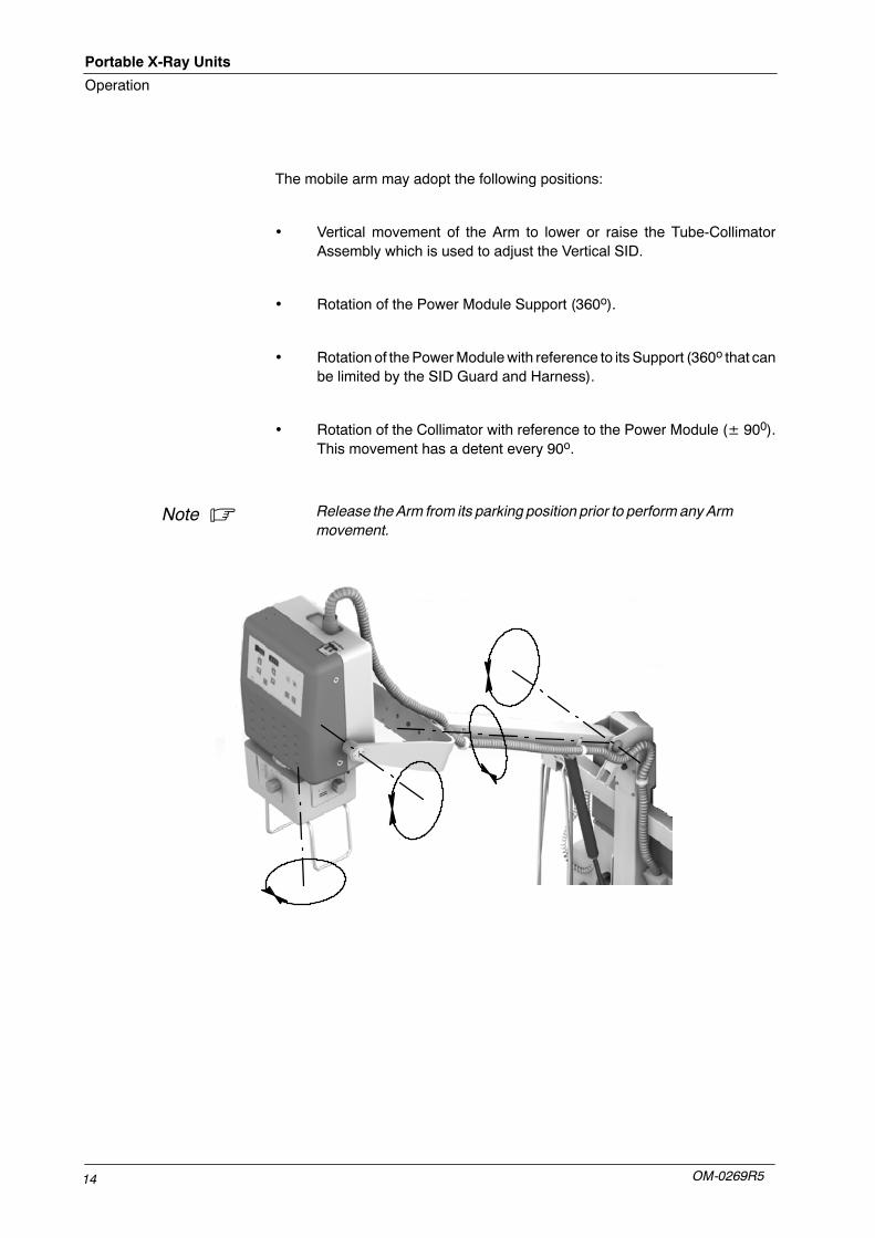
The mobile arm may adopt the following positions:
• Vertical movement of the Arm to lower or raise the Tube-CollimatorAssembly which is used to adjust the Vertical SID.
• Rotation of the Power Module Support (360o).
• Rotation of thePowerModulewith reference to its Support (360o that canbe limited by the SID Guard and Harness).
• Rotation of the Collimator with reference to the Power Module (± 900).This movement has a detent every 90o.
Release theArm from its parking position prior to perform anyArmmovement.
Note .
Portable X-Ray Units
Operation
OM-0269R5 15
3.1 MOBILE UNIT
ALWAYS DRIVE OR TRANSPORT THE UNIT WITH THE ARMIN PARKING POSITION. FOR SAFETY REASONS, THEFLOOR WILL NOT EXCEED 5o INCLINATION (RAMPS).
MONITORTHESYSTEMMOVEMENTSWITHSPECIALCARE.AVOID ANY IMPACT OF THE UNIT ON WALLS, FURNITUREOR OTHER ELEMENTS IN THE ROOM THAT MAY CAUSEDAMAGE TO THE EQUIPMENT.
MONITORWITH SPECIAL CARE THEPATIENT POSITIONORANY OTHER PEOPLE, TO AVOID INJURY CAUSED BY UNITMOVEMENTS. INTRAVENOUS TUBING, CATHETERS ANDOTHER PATIENT CONNECTED LINES SHOULD BE ROUTEDAWAY FROM MOVING EQUIPMENT.
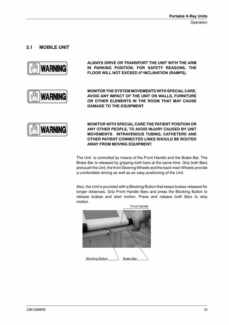
The Unit is controlled by means of the Front Handle and the Brake Bar. TheBrake Bar is released by gripping both bars at the same time. Grip both Barsand push theUnit, the front SteeringWheels and the backmainWheels providea comfortable driving as well as an easy positioning of the Unit.
Also, the Unit is provided with a Blocking Button that keeps brakes released forlonger distances. Grip Front Handle Bars and press the Blocking Button torelease brakes and start motion. Press and release both Bars to stopmotion.
Blocking Button
Front Handle
Brake Bar
Portable X-Ray Units
Operation
OM-0269R516
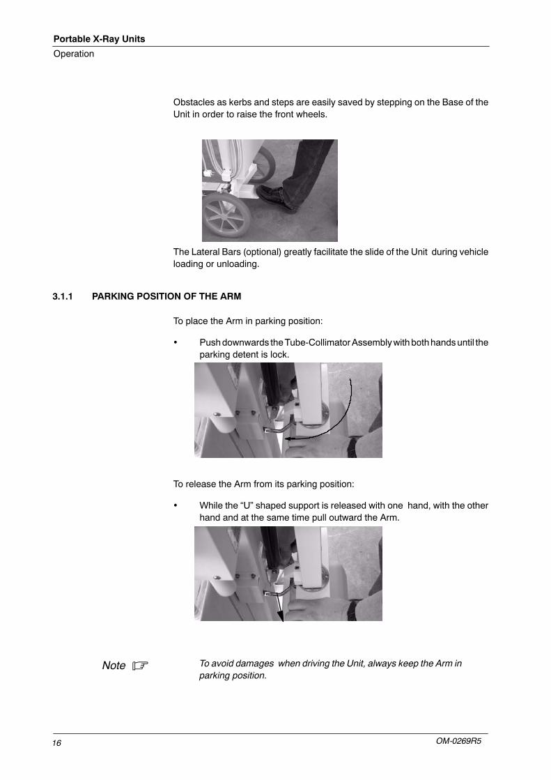
Obstacles as kerbs and steps are easily saved by stepping on the Base of theUnit in order to raise the front wheels.
The Lateral Bars (optional) greatly facilitate the slide of the Unit during vehicleloading or unloading.
3.1.1 PARKING POSITION OF THE ARM
To place the Arm in parking position:
• Pushdownwards theTube-CollimatorAssemblywithbothhandsuntil theparking detent is lock.
To release the Arm from its parking position:
• While the “U” shaped support is released with one hand, with the otherhand and at the same time pull outward the Arm.
To avoid damages when driving the Unit, always keep the Arm inparking position.
Note .
Portable X-Ray Units
Operation
OM-0269R5 17
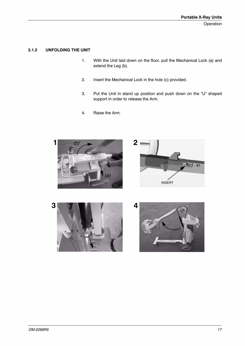
3.1.2 UNFOLDING THE UNIT
1. With the Unit laid down on the floor, pull the Mechanical Lock (a) andextend the Leg (b).
2. Insert the Mechanical Lock in the hole (c) provided.
3. Put the Unit in stand up position and push down on the “U” shapedsupport in order to release the Arm.
4. Raise the Arm.
(b)
(a)
1 2
3 4
INSERT
(c)
Portable X-Ray Units
Operation
OM-0269R518
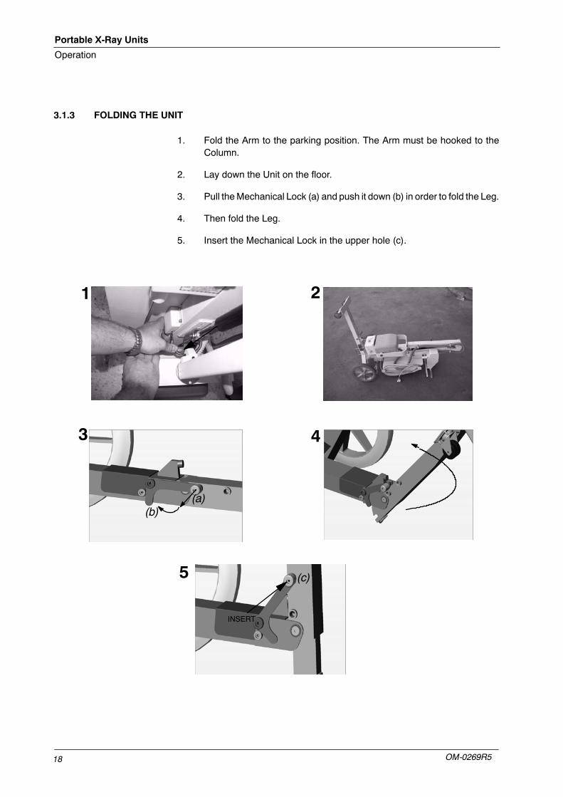
3.1.3 FOLDING THE UNIT
1. Fold the Arm to the parking position. The Arm must be hooked to theColumn.
2. Lay down the Unit on the floor.
3. Pull theMechanical Lock (a) and push it down (b) in order to fold the Leg.
4. Then fold the Leg.
5. Insert the Mechanical Lock in the upper hole (c).
3
1 2
4
(a)(b)
INSERT
5 (c)
Portable X-Ray Units
Operation
OM-0269R5 19
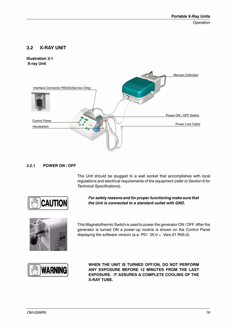
3.2 X-RAY UNIT
Illustration 3-1X-ray Unit
Manual Collimator
Power ON / OFF Switch
Control PanelPower Line Cable
Handswitch
Interface Connector RS232(Service Only)
3.2.1 POWER ON / OFF
The Unit should be plugged to a wall socket that accomplishes with localregulations and electrical requirements of the equipment (refer to Section 6 forTechnical Specifications).
For safety reasons and for proper functioningmake sure thatthe Unit is connected to a standard outlet with GND.
ThisMagnetothermic Switch is used to power the generator ON /OFF. After thegenerator is turned ON a power-up routine is shown on the Control Paneldisplaying the software version (a.e. P01 05.0 = Vers.01 R05.0).
WHEN THE UNIT IS TURNED OFF/ON, DO NOT PERFORMANY EXPOSURE BEFORE 12 MINUTES FROM THE LASTEXPOSURE. IT ASSURES A COMPLETE COOLING OF THEX-RAY TUBE.
Portable X-Ray Units
Operation
OM-0269R520
3.2.2 AUTOMATIC POWER LINE DETECTION SYSTEM
By means of this System, the Unit detects the maximum operative Power Lineadapting the Exposure Parameters to the Power available and avoidingundesired line breakdowns when operating with poor electricity lines.
1. Press and hold the “Collimator Lamp” push-button and then turn the Unit“ON”. The Display shows “LPd ACT” (Line Power Detection Active).
2. Release the “Collimator Lamp” push-button, the Display shows “LPDP-E” (Line Power Detection Preparation-Exposition).
3. Press “Prep”, count to five (5) and then press and hold “X-Ray ON” untilthree (3) consecutive exposures are performed.
At this moment, if the X-ray Tube is too hot, the Display shows “LPd StP”(very uncommon), if this is the case, wait for the Tube to cool and repeatprocedure.
4. Release “X-Ray ON” button, the procedure has finished and the Displayshows normal parameters. Now the Unit has detected the maximumPower Line that can be used normal operation.
If error code E95 appears at this moment, it means that the line is notgood enough and exposures will not be allowed, if possible, change theUnit Plug to another socket (line).
If any error code (other than E95) appears on Display duringprocedure, reset it with “Collimator Lamp” push-button.
Note .
Portable X-Ray Units
Operation
OM-0269R5 21
Once the Line Power Detection Procedure is performed:
• It is not necessary to perform the Warm Up procedure.
• Perform the procedure every time theUnit is plugged in a different socketas the Unit applies the data of the last Power Line acknowledged.
• After finishing the procedure, the Heat Units value is reduced to theapprox. 70%, wait a few minutes for the Tube to cool.
• This procedure does not take into account the limitations of theMagnetothermic Breaker installed at site. If the MagnetothermicBreaker installed at site still goes down, perform the Manual PowerReduction procedure below.
3.2.3 MANUAL POWER REDUCTION
The operator may select the maximum Power percentage used by the Unit inorder to avoid blown fuses or Circuit Breakers down in poor electricity lines. Forthat, press and hold any “Focal Spot” push-button and increase or decrease thepercentage by pressing the “kVp Increase o Decrease” push-buttonsrespectively.
The kVpDisplay shows thePower percentage selected in 10%steps, precededby the letter “P”. For example, a display of “P80”would indicate that the Powerof the Unit will be limited to a maximum of 80%. “P -- -- ” indicates that the Unitwill operate at full Power (100% -- factory set).
In case a technique exceeds the power required, the kVp andmAs displays willblink, modify the technique or modify Power percentage.
Portable X-Ray Units
Operation
OM-0269R522
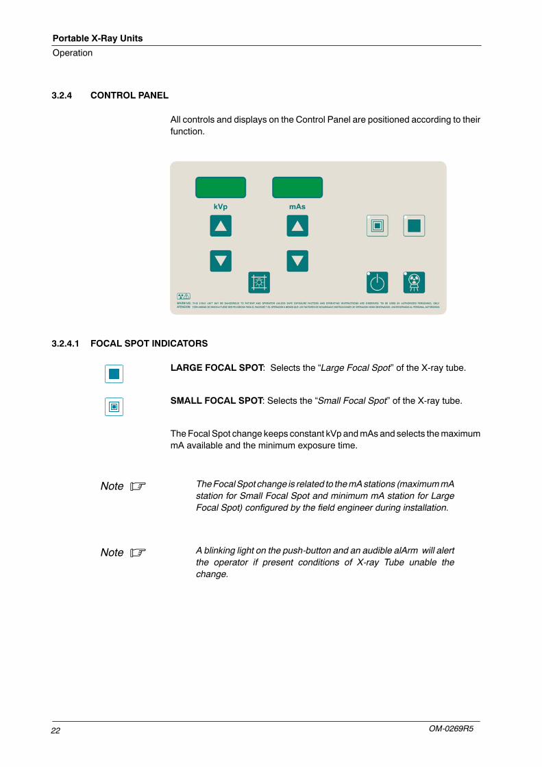
3.2.4 CONTROL PANEL
All controls and displays on the Control Panel are positioned according to theirfunction.
3.2.4.1 FOCAL SPOT INDICATORS
LARGE FOCAL SPOT: Selects the “Large Focal Spot” of the X-ray tube.
SMALL FOCAL SPOT: Selects the “Small Focal Spot” of the X-ray tube.
The Focal Spot change keeps constant kVp andmAs and selects themaximummA available and the minimum exposure time.
TheFocalSpot change is related to themAstations (maximummAstation for Small Focal Spot and minimum mA station for LargeFocal Spot) configured by the field engineer during installation.
A blinking light on the push-button and an audible alArm will alertthe operator if present conditions of X-ray Tube unable thechange.
Note .
Note .
Portable X-Ray Units
Operation
OM-0269R5 23
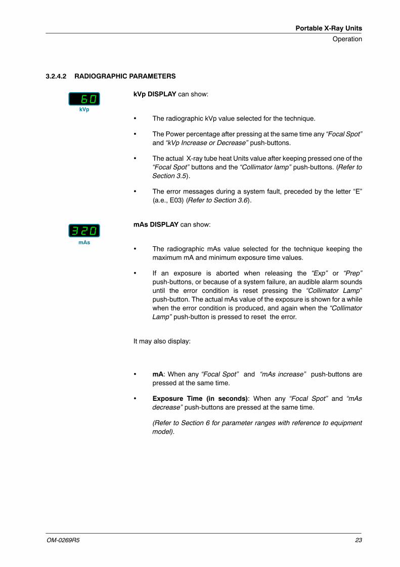
3.2.4.2 RADIOGRAPHIC PARAMETERS
kVp DISPLAY can show:
• The radiographic kVp value selected for the technique.
• The Power percentage after pressing at the same time any “Focal Spot”and “kVp Increase or Decrease” push-buttons.
• The actual X-ray tube heat Units value after keeping pressed one of the“Focal Spot” buttons and the “Collimator lamp” push-buttons. (Refer toSection 3.5).
• The error messages during a system fault, preceded by the letter “E”(a.e., E03) (Refer to Section 3.6).
mAs DISPLAY can show:
• The radiographic mAs value selected for the technique keeping themaximum mA and minimum exposure time values.
• If an exposure is aborted when releasing the “Exp” or “Prep”push-buttons, or because of a system failure, an audible alarm soundsuntil the error condition is reset pressing the “Collimator Lamp”push-button. The actual mAs value of the exposure is shown for a whilewhen the error condition is produced, and again when the “CollimatorLamp” push-button is pressed to reset the error.
It may also display:
• mA: When any “Focal Spot” and “mAs increase” push-buttons arepressed at the same time.
• Exposure Time (in seconds): When any “Focal Spot” and “mAsdecrease” push-buttons are pressed at the same time.
(Refer to Section 6 for parameter ranges with reference to equipmentmodel).
kVp
mAs
Portable X-Ray Units
Operation
OM-0269R524
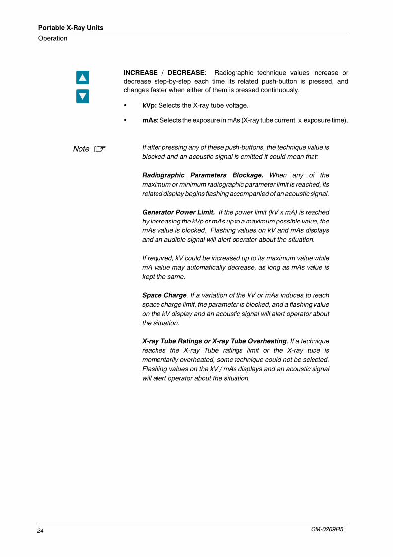
INCREASE / DECREASE: Radiographic technique values increase ordecrease step-by-step each time its related push-button is pressed, andchanges faster when either of them is pressed continuously.
• kVp: Selects the X-ray tube voltage.
• mAs: Selects theexposure inmAs (X-ray tube current x exposure time).
If after pressing any of these push-buttons, the technique value isblocked and an acoustic signal is emitted it could mean that:
Radiographic Parameters Blockage. When any of themaximum orminimum radiographic parameter limit is reached, itsrelateddisplay begins flashingaccompaniedof anacoustic signal.
Generator Power Limit. If the power limit (kV x mA) is reachedby increasing the kVp ormAs up to amaximumpossible value, themAs value is blocked. Flashing values on kV and mAs displaysand an audible signal will alert operator about the situation.
If required, kV could be increased up to its maximum value whilemA value may automatically decrease, as long as mAs value iskept the same.
Space Charge. If a variation of the kV or mAs induces to reachspace charge limit, the parameter is blocked, and a flashing valueon the kV display and an acoustic signal will alert operator aboutthe situation.
X-ray Tube Ratings or X-ray Tube Overheating. If a techniquereaches the X-ray Tube ratings limit or the X-ray tube ismomentarily overheated, some technique could not be selected.Flashing values on the kV / mAs displays and an acoustic signalwill alert operator about the situation.
Note .
Portable X-Ray Units
Operation
OM-0269R5 25
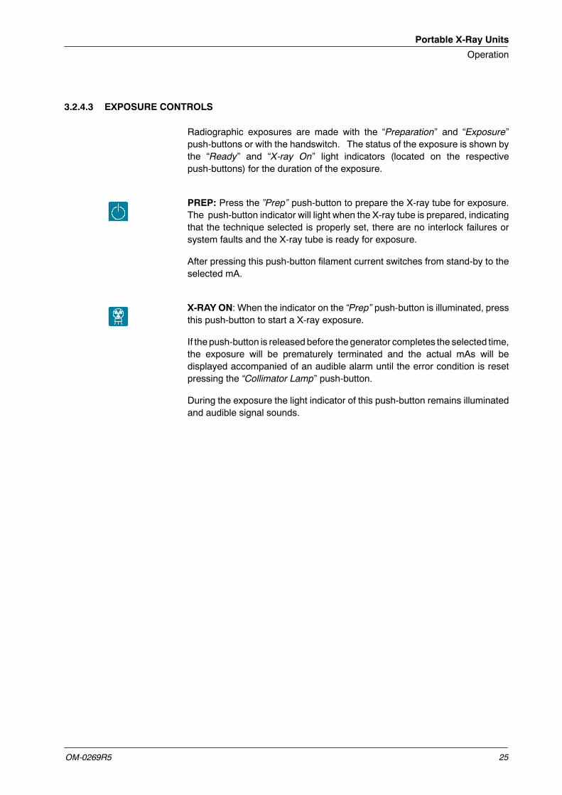
3.2.4.3 EXPOSURE CONTROLS
Radiographic exposures are made with the “Preparation” and “Exposure”push-buttons or with the handswitch. The status of the exposure is shown bythe “Ready” and “X-ray On” light indicators (located on the respectivepush-buttons) for the duration of the exposure.
PREP: Press the ”Prep” push-button to prepare the X-ray tube for exposure.The push-button indicator will light when the X-ray tube is prepared, indicatingthat the technique selected is properly set, there are no interlock failures orsystem faults and the X-ray tube is ready for exposure.
After pressing this push-button filament current switches from stand-by to theselected mA.
X-RAY ON: When the indicator on the “Prep” push-button is illuminated, pressthis push-button to start a X-ray exposure.
If the push-button is releasedbefore the generator completes the selected time,the exposure will be prematurely terminated and the actual mAs will bedisplayed accompanied of an audible alarm until the error condition is resetpressing the “Collimator Lamp” push-button.
During the exposure the light indicator of this push-button remains illuminatedand audible signal sounds.
Portable X-Ray Units
Operation
OM-0269R526
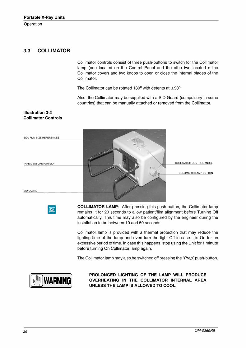
3.3 COLLIMATOR
Collimator controls consist of three push-buttons to switch for the Collimatorlamp (one located on the Control Panel and the othe two located n theCollimator cover) and two knobs to open or close the internal blades of theCollimator.
The Collimator can be rotated 1800 with detents at ±90o.
Also, the Collimator may be supplied with a SID Guard (compulsory in somecountries) that can be manually attached or removed from the Collimator.
Illustration 3-2Collimator Controls
COLLIMATOR CONTROL KNOBSTAPE MEASURE FOR SID
SID / FILM SIZE REFERENCES
SID GUARD
COLLIMATOR LAMP BUTTON
COLLIMATOR LAMP: After pressing this push-button, the Collimator lampremains lit for 20 seconds to allow patient/film alignment before Turning Offautomatically. This time may also be configured by the engineer during theinstallation to be between 10 and 50 seconds.
Collimator lamp is provided with a thermal protection that may reduce thelighting time of the lamp and even turn the light Off in case it is On for anexcessive period of time. In case this happens, stop using the Unit for 1 minutebefore turning On Collimator lamp again.
The Collimator lampmay also be switched off pressing the “Prep” push-button.
PROLONGED LIGHTING OF THE LAMP WILL PRODUCEOVERHEATING IN THE COLLIMATOR INTERNAL AREAUNLESS THE LAMP IS ALLOWED TO COOL.
Portable X-Ray Units
Operation
OM-0269R5 27
COLLIMATOR LAMP WITH LASER POSITIONER (OPTIONAL): Afterpressing the Collimator Lamp push-button, a cross-shaped Laser light pointsat the patient and after one second the Collimator Lamp lights. They remainlighting for 20 seconds before they switch Off automatically. The light timemayalso be configured between 10 and 50 seconds by the engineer during theinstallation.
The Laser pointer also lits when “Prep” is pushed, then the Collimator lampswitches off.
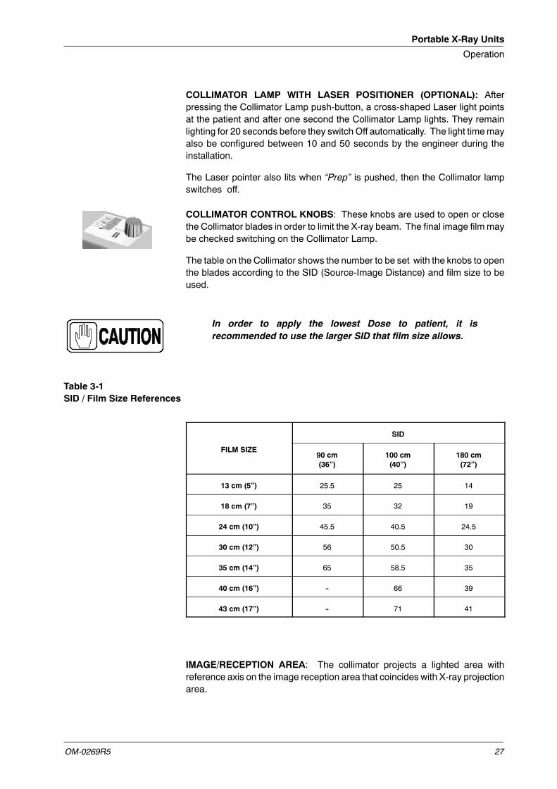
COLLIMATOR CONTROL KNOBS: These knobs are used to open or closethe Collimator blades in order to limit the X-ray beam. The final image filmmaybe checked switching on the Collimator Lamp.
The table on the Collimator shows the number to be set with the knobs to openthe blades according to the SID (Source-Image Distance) and film size to beused.
In order to apply the lowest Dose to patient, it isrecommended to use the larger SID that film size allows.
Table 3-1SID / Film Size References
SID
FILM SIZE90 cm(36”)
100 cm(40”)
180 cm(72”)
13 cm (5”) 25.5 25 14
18 cm (7”) 35 32 19
24 cm (10”) 45.5 40.5 24.5
30 cm (12”) 56 50.5 30
35 cm (14”) 65 58.5 35
40 cm (16”) -- 66 39
43 cm (17”) -- 71 41
IMAGE/RECEPTION AREA: The collimator projects a lighted area withreference axis on the image reception area that coincides with X-ray projectionarea.
Portable X-Ray Units
Operation
OM-0269R528
3.4 X-RAY HANDSWITCH
Radiographic exposures may also be initiated with the X-ray handswitch whichis connected to the Control Panel.
The X-ray handswitch button has three positions: “Off”, “Preparation”, and“X-ray Exposure”, which operate in the same way that “Prep” and “Exp”push-buttons on the Control Panel.
Press the handswitch half-way for “Prep” and fully for “Exp”.
3.5 HEAT UNITS AND TEMPERATURE OF POWER MODULE
This X-ray Unit is equipped with a Heat Unit Calculator for the X-ray Tube andaTemperatureCalculator for thePowerModule.Both valuesare calculatedandtotalled during exposures. They can be displayed on the Unit after pressing the“Collimator Lamp” and any of the “Focal Spot” push-buttons.
The kVp Display shows the percentage of Heat Units that remain preceded bythe letter “H”. For example, a display of “H75”would indicate that 75%of HeatUnits capacity of the X-ray Tube remains. “H -- -- ” indicates that full capacityremains (100%).
The mAs Display shows the Temperature in Celsius Degrees preceded by theletter “t”. For example, a display of “t32”would indicate 32oC. If a new selectionof parameters overpass 90oC, exposure is inhibited and values in displays blinkaccompanied by an alarm. Reduce parameter values or wait for the unit to cool.
Both displays revert to its normal function after releasing any of thepush-buttons.
When the Unit is turned OFF/ON, both values are reset and indicate that fullcapacity of Heat units remain and the temperature calculator starts at 30oC.This may produce an erroneous calculation of Heat Units or Temperature if theX-rayUnit is not fully cold (12minutes have to beelapsed from the last exposurebefore performing the next exposure).
Prep
OFF
Exp
Portable X-Ray Units
Operation
OM-0269R5 29
3.6 ERROR CODES
Error codes indicate the potential cause of a system failure. They areintermittently shown on the kV Display at the same time an alarm sounds. Ingeneral, to remove the error condition press the “Collimator Lamp” (Refer toTable 3-2).
All these error codes are preceded by the letter “E” (a.e., E03) and they willenable the operator to indirectly convey the possible source of error to servicepersonnel. This may prevent the need for a service call or enable servicepersonnel to anticipate corrective actions prior to arriving in site.
Table 3-2Error Codes
ERROR DESCRIPTION WHAT TO DO
E03 Wrong configuration of the X-ray Tube. Turn the Unit OFF and call Field Service.
E06“Exposure” or/and “Preparation” orders are activatedduring power-up.
Release all the controls.Turn the Unit OFF and ON.If the equipment remains inoperative, turn it OFF and callField Service.
E08 X-ray Tube configuration error. Press the “Collimator Lamp” push-button.If the error code persists turn the Unit OFF and ON
E09System error -- Power Inverter error due toovercurrent.
If the error code persists, turn the Unit OFF and ON.If the equipment remains inoperative, turn it OFF and callField Service.
E10 Corrupted data in E2PROM.Turn the Unit OFF and ON.If the equipment remains inoperative, turn it OFF and callField Service.
E11 System error -- DC BUS error.
Press the “Collimator Lamp” push-button.If the error code persists, turn the Unit OFF and ON.If the equipment remains inoperative, turn it OFF and callField Service.
E12mA is out of range during exposure or exposure hasbeen aborted by the Operator.
Press the “Collimator Lamp” push-button.Repeat exposure with same technique values, If the errorcode persists try exposure with another combination of
E13kV is out of range during exposure or exposure hasbeen aborted by the Operator.
code persists try exposure with another combination oftechnique values.If the equipment remains inoperative, turn it OFF and callField Service.
E15 Filament or Collimator Lamp current is out of range.
Press the “Collimator Lamp” push-button.If the error code persists, turn the Unit OFF and wait30 minutes before turning it ON again.If the equipment remains inoperative, turn it OFF and callField Service.
E19 mA without exposure order. Press the “Collimator Lamp” push-button.If the error code persists, turn the Unit OFF and ON.
E20 kV without exposure order.
If the error code persists, turn the Unit OFF and ON.If the equipment remains inoperative, turn it OFF and callField Service.
Portable X-Ray Units
Operation
OM-0269R530
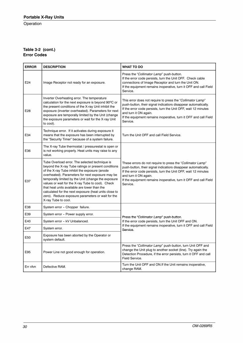
Table 3-2 (cont.)Error Codes
ERROR DESCRIPTION WHAT TO DO
E24 Image Receptor not ready for an exposure.
Press the “Collimator Lamp” push-button.If the error code persists, turn the Unit OFF. Check cableconnections of Image Receptor and turn the Unit ON.If the equipment remains inoperative, turn it OFF and call FieldService.
E28
Inverter Overheating error. The temperaturecalculation for the next exposure is beyond 90oC orthe present conditions of the X-ray Unit inhibit theexposure (inverter overheated). Parameters for nextexposure are temporally limited by the Unit (changethe exposure parameters or wait for the X-ray Unitto cool).
This error does not require to press the “Collimator Lamp”push-button, their signal indicatiors disappear automatically.If the error code persists, turn the Unit OFF, wait 12 minutesand turn it ON again.If the equipment remains inoperative, turn it OFF and call FieldService.
E34Technique error. If it activates during exposure itmeans that the exposure has been interrupted bythe “Security Timer” because of a system failure.
Turn the Unit OFF and call Field Service.
E36The X-ray Tube thermostat / pressurestat is open oris not working properly. Heat units may raise to anyvalue.
E37
Tube Overload error. The selected technique isbeyond the X-ray Tube ratings or present conditionsof the X-ray Tube inhibit the exposure (anodeoverheated). Parameters for next exposure may betemporally limited by the Unit (change the exposurevalues or wait for the X-ray Tube to cool). Checkthat heat units available are lower than thecalculated for the next exposure (heat units close tozero). Reduce exposure parameters or wait for theX-ray Tube to cool.
These errors do not require to press the “Collimator Lamp”push-button, their signal indicatiors disappear automatically.If the error code persists, turn the Unit OFF, wait 12 minutesand turn it ON again.If the equipment remains inoperative, turn it OFF and call FieldService.
E38 System error -- Chopper failure.
E39 System error -- Power supply error.Press the “Collimator Lamp” push-button
E40 System error -- kV Unbalanced.Press the “Collimator Lamp” push-button.If the error code persists, turn the Unit OFF and ON.If h i i i i i OFF d ll Fi ld
E47 System error.
pIf the equipment remains inoperative, turn it OFF and call FieldService.
E50Exposure has been aborted by the Operator orsystem default.
Service.
E95 Power Line not good enough for operation.
Press the “Collimator Lamp” push-button, turn Unit OFF andchange the Unit plug to another socket (line). Try again theDetection Procedure, if the error persists, turn it OFF and callField Service.
Err rAm Defective RAM.Turn the Unit OFF and ON.If the Unit remains inoperative,change RAM.
Portable X-Ray Units
Operation
OM-0269R5 31
SECTION 4 OPERATING SEQUENCES
4.1 START-UP ROUTINE
The Unit turns ON when the magnetothermic switch is set upward (ON). TheUnit will go through a start-up routine conducting an automatic self-test. TheDisplay will show information usable only by service personnel.
Once the power-up has been completed, the Control Panel should displaynormal radiographic factors. If a malfunction is found, error messages will bedisplayed.
Some indicators on the Control Panel are used to provide serviceinformation during the start-up process. These indicators shouldbe ignored by the operator until the unit has completed itspower-up sequence.
4.2 X-RAY TUBE SEASONING AND X-RAY TUBE WARMING-UP
TheSeasoning andWarning-up procedures assure a correct operation of theX-ray Tube andmust be properly carried out. Otherwise the X-ray Tube lifemaybe considerably reduced or the X-ray tube will suffer a permanent damage.
The Seasoning Procedure (Running) must be performed when the Tube isused for the first time or when it has not been in use for more than one month.This action establishes a favorable distribution of the electrical charges andelectrostatic stresses in the insulation system of the Tube and the associatedequipment. Not performing the Seasoning Procedure causes loss of the X-rayTube Warranty.
TheWarming-up Proceduremust be performed at the start of each day or onehour after the last exposure.
Before performing X-ray exposures ensure that the tube isproperly warmed-up. Make sure that no persons will beinadvertently exposed to unnecessary X-rays during thisprocedure.
Note .
Portable X-Ray Units
Operation
OM-0269R532
4.2.1 SEASONING PROCEDURE (RUNNING) (AFTER ONE MONTH)
1. CloseCollimator Blades fully andmake sure that no onewill be exposed.
2. Make sure that X-ray Tube is fully cold (at least 30 minutes withoutmaking exposures).
3. Select 70 kVp, 10 mAs and Large Focus. Perform one exposure perminute increasing 5 kVp in every exposure up to the maximum Tubevoltage.
4. If there are not signs of instability, the tube is ready for normal use.
5. If instability is observed during procedure, reduce 5 kVp of the selectedkVp and make two successive exposures, then continue the process.
Check that the Heat Units capacity is above 80% during thisprocess.
4.2.2 WARMING-UP PROCEDURE (EVERY DAY)
1. CloseCollimator Blades fully andmake sure that no onewill be exposed.
2. Select 50 kVp, 20 mAs and Large Focus.
3. Perform a total of three exposures, 15 seconds apart.
4. Now the Tube is ready for normal use.
Excessive filament evaporation shortens X-ray tube life.Minimize evaporation by keeping Exposure “Preparation”time to an absolute minimum.
Note .
Portable X-Ray Units
Operation
OM-0269R5 33
4.3 RADIOGRAPHIC OPERATION
A typical examination sequence is as indicated below:
1. Make sure that the X-ray tube is properly warmed-up.
2. Position the patient for the examination.
3. Maintain the patient at the required position. Prepare the X-ray tube bypressing the handswitch push-button to the “Prep” position andmaintainit until the “Ready” indicator is illuminated.
4. Make the X-ray exposure pressing the handswitch push-button fully tothe “Exp” position and maintain it throughout the exposure. Then, the“X-ray On” indicator will light and an audible signal will sound during theexposure.
5. When the exposure is finished, release the push-button.
6. Repeat the procedure if additional exposures are desired.

Portable X-Ray Units
Operation
OM-0269R534
This page intentionally left blank.
Portable X-Ray Units
Operation
OM-0269R5 35
SECTION 5 PERIODIC MAINTENANCE
In order to assure continuous safe performance of the X-ray Unit, a periodicmaintenance programmust be established. It is the owner’s responsibility tosupply or arrange for this service.
There are two levels of maintenance, the first consists of tasks which areperformed by the user/operator, and the second are those tasks to beperformed by qualified X-ray service personnel.
The first periodicmaintenance service should be performed six (6)months afterinstallation, and the subsequent services at twelve (12) month intervals.
The manufacturer undertakes to have available spare parts for this equipmentat least for five (5) years after the unit manufacturing.
5.1 OPERATOR TASKS
The tasks of this periodic maintenance shall include the following items:
DO NOT REMOVE ANY COVER, DISASSEMBLE ORMANIPULATE INTERNAL COMPONENTS IN THE UNIT.THESE ACTIONS COULD CAUSE SERIOUS PERSONALINJURIES AND / OR DAMAGE TO EQUIPMENT.
NEVERATTEMPTTOCLEANANYPARTOFTHEUNIT WHENIT ISSWITCHEDON. ALWAYSSWITCHOFFTHEEQUIPMENTAND ISOLATE THE MAINS ELECTRICAL SUPPLY BEFORECLEANING.
1. Switch the Unit OFF.
2. Externally, check the proper cable connections between eachcomponent in the X-ray system.
3. Clean the equipment frequently, particularly if corroding chemicals arepresent. Clean external covers and surfaces with a cloth moistened inwarm water with mild soap. Wipe with a cloth moistened in clean water.Do not use cleaners or solvents of any kind.
Portable X-Ray Units
Operation
OM-0269R536
5.2 SERVICE TASKS
Only service personnel specifically trained on this medical X-ray equipmentshould work on service tasks or maintenance of the equipment. (Refer to“Maintenance” Section of the Service Manual.)
Portable X-Ray Units
Operation
OM-0269R5 37
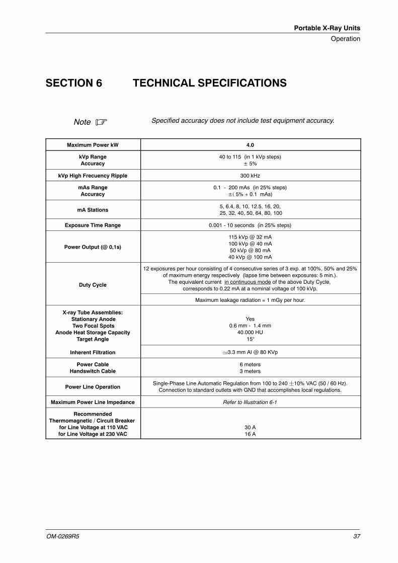
SECTION 6 TECHNICAL SPECIFICATIONS
Specified accuracy does not include test equipment accuracy.
Maximum Power kW 4.0
kVp RangeAccuracy
40 to 115 (in 1 kVp steps)± 5%
kVp High Frecuency Ripple 300 kHz
mAs RangeAccuracy
0.1 - 200 mAs (in 25% steps)±( 5% + 0.1 mAs)
mA Stations5, 6.4, 8, 10, 12.5, 16, 20,25, 32, 40, 50, 64, 80, 100
Exposure Time Range 0.001 - 10 seconds (in 25% steps)
Power Output (@ 0,1s)
115 kVp @ 32 mA100 kVp @ 40 mA50 kVp @ 80 mA40 kVp @ 100 mA
Duty Cycle
12 exposures per hour consisting of 4 consecutive series of 3 exp. at 100%, 50% and 25%of maximum energy respectively (lapse time between exposures: 5 min.).The equivalent current in continuous mode of the above Duty Cycle,
corresponds to 0.22 mA at a nominal voltage of 100 kVp.
Maximum leakage radiation = 1 mGy per hour.
X-ray Tube Assemblies:Stationary AnodeTwo Focal Spots
Anode Heat Storage CapacityTarget Angle
Yes0.6 mm - 1.4 mm
40.000 HU15°
Inherent Filtration '3.3 mm Al @ 80 KVp
Power CableHandswitch Cable
6 meters3 meters
Power Line OperationSingle-Phase Line Automatic Regulation from 100 to 240¦10% VAC (50 / 60 Hz).Connection to standard outlets with GND that accomplishes local regulations.
Maximum Power Line Impedance Refer to Illustration 6-1
RecommendedThermomagnetic / Circuit Breaker
for Line Voltage at 110 VACfor Line Voltage at 230 VAC
30 A16 A
Note .
Portable X-Ray Units
Operation
OM-0269R538
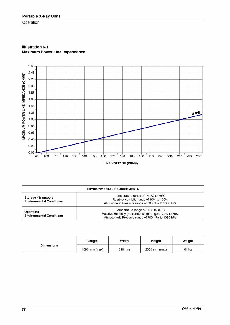
Illustration 6-1Maximum Power Line Impendance
0.08
0.28
0.48
0.68
0.88
1.08
1.28
1.48
1.68
1.88
2.08
2.28
2.48
2.68
90 100 110 120 130 140 150 160 170 180 190 200 210 220 230 240 250 260
LINE VOLTAGE (VRMS)
MAXIMUMPOWERLINEIMPEDANCE(OHMS)
ENVIRONMENTAL REQUIREMENTS
Storage / TransportEnvironmental Conditions
Temperature range of --40oC to 70oCRelative Humidity range of 10% to 100%
Atmospheric Pressure range of 500 hPa to 1060 hPa
OperatingEnvironmental Conditions
Temperature range of 10oC to 40oCRelative Humidity (no condensing) range of 30% to 75%Atmospheric Pressure range of 700 hPa to 1060 hPa
Di iLength Width Height Weight
Dimensions1590 mm (max) 619 mm 2380 mm (max) 61 kg
Portable X-Ray Units
Operation
OM-0269R5 39
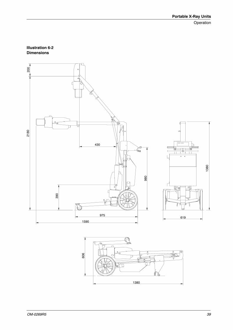
Illustration 6-2Dimensions
430
2180
390
980
1590
975619
606
1380
200
1380
Portable X-Ray Units
Operation
OM-0269R540
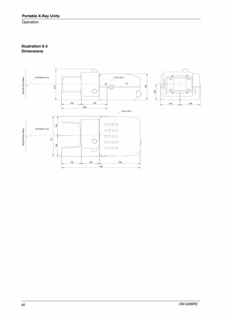
Illustration 6-3Dimensions