Embed Size (px)
Citation preview
System for Environmental and Agricultural Modelling; Linking European Science and Society
Report no.: 7 December 2005 Ref.: D5.3.1 ISBN no.: 90-8585-035-5
Overall architectural design of SeamFrame
A.E. Rizzoli, I.N. Athanasiadis, M. Donatelli, D. Huber, R. Muetzelfeldt, F.K. van Evert, M. van de Broek, T. van der Wal,
F. Villa
Partners involved: IDSIA, Alterra, CRA, PRI, Simulistics, UVM
Logo’s main partners involved in this publication Sixth Framework Programme
SEAMLESS No. 010036 Deliverable number: D5.3.1 19 December 2005
Page 2 of 34
SEAMLESS integrated project aims at developing an integrated framework that allows ex-ante assessment of agricultural and environmental policies and technological innovations. The framework will have multi-scale capabilities ranging from field and farm to the EU25 and globe; it will be generic, modular and open and using state-of-the art software. The project is carried out by a consortium of 30 partners, led by Wageningen University (NL). Email: [email protected] Internet: www.seamless-ip.org
Authors of this report and contact details
Name: Andrea Emilio Rizzoli Partner acronym: IDSIA Address: IDSIA, Galleria 2, 6928 Manno, Switzerland. E-mail: [email protected]
Name: Ioannis Athanasiadis Partner acronym: IDSIA Address: IDSIA, Galleria 2, 6928 Manno, Switzerland. E-mail: [email protected]
Name: Marcello Donatelli Partner acronym: CRA-ISCI Address: ISCI, Via di Corticella, 133, 40128 Bologna, Italy E-mail: [email protected]
Name: David Huber Partner acronym: IDSIA Address: IDSIA, Galleria 2, 6928 Manno, Switzerland. E-mail: [email protected]
Name: Robert Muetzelfeldt Partner acronym: Simulistics Address: Simulistics, 11 Tantallon Place, Edinburgh, EH9 1NZ, Scotland, UK E-mail: [email protected]
Name: Frits van Evert Partner acronym: PRI Address: PRI - Wageningen University, PO Box 16, 6700 AA Wageningen, the Netherlands E-mail: [email protected]
Name: Machteld van den Broek Partner acronym: Alterra Address: Alterra, PO Box 47, 6700 AA Wageningen, the Netherlands E-mail: [email protected]
Name: Tamme van der Wal Partner acronym: Alterra Address: Alterra, PO Box 47, 6700 AA Wageningen, the Netherlands E-mail: [email protected]
Name: Ferdinando Villa Partner acronym: UVM Address: University of Vermont, 590 Main Street, Burlington, 05405, Vermont, USA E-mail: [email protected]
SEAMLESS No. 010036 Deliverable number: D5.3.1 19 December 2005
Page 3 of 34
Disclaimer 1: “This publication has been funded under the SEAMLESS integrated project, EU 6th Framework Programme for Research, Technological Development and Demonstration, Priority 1.1.6.3. Global Change and Ecosystems (European Commission, DG Research, contract no. 010036-2). Its content does not represent the official position of the European Commission and is entirely under the responsibility of the authors.” "The information in this document is provided as is and no guarantee or warranty is given that the information is fit for any particular purpose. The user thereof uses the information at its sole risk and liability." Disclaimer 2: Within the SEAMLESS project many reports are published. Some of these reports are intended for public use, others are confidential and intended for use within the SEAMLESS consortium only. As a consequence references in the public reports may refer to internal project deliverables that cannot be made public outside the consortium. When citing this SEAMLESS report, please do so as: Rizzoli, A.E., Athanasiadis, I.N., Donatelli, M., Huber, D., Muetzelfeldt, R., et al., 2005. Overall architectural design of SeamFrame, SEAMLESS Report No.7, SEAMLESS integrated project, EU 6th Framework Programme, contract no. 010036-2, www.SEAMLESS-IP.org, 34 pp, ISBN no. 90-8585-035-5.

SEAMLESS No. 010036 Deliverable number: D5.3.1 19 December 2005
Page 5 of 34
Table of contents Table of contents.................................................................................................................................... 5
General part ........................................................................................................................................... 7
Objective within the project ................................................................................................................. 7
General Information ............................................................................................................................. 7
Executive summary ............................................................................................................................... 7
Scientific and societal relevance ........................................................................................................... 8
Specific part ......................................................................................................................................... 11
1 The SeamFrame system model............................................................................................. 11
2 The Knowledge Base ............................................................................................................. 13 2.1 Purpose and goals................................................................................................................... 13 2.2 User classes............................................................................................................................. 13 2.3 Functions provided.................................................................................................................. 14
3 The Core................................................................................................................................. 15 3.1 Components............................................................................................................................. 15 3.2 Classes .................................................................................................................................... 15
3.2.1 The Domain class ............................................................................................ 15 3.2.2 The Model class............................................................................................... 16
3.3 The Domain Manager Framelet.............................................................................................. 18 3.3.1 Purpose and goals............................................................................................ 18 3.3.2 User classes ..................................................................................................... 18 3.3.3 Functions provided .......................................................................................... 18
3.4 The Model Manager Framelet ................................................................................................ 19 3.4.1 Purpose and scope of the Model Manager....................................................... 19 3.4.2 User classes ..................................................................................................... 19 3.4.3 Functions provided .......................................................................................... 19
3.5 The Tool Maker Framelet ....................................................................................................... 20 3.5.1 Purpose and scope ........................................................................................... 20 3.5.2 User classes ..................................................................................................... 21 3.5.3 Functions provided .......................................................................................... 21
4 The Development Environment ........................................................................................... 23 4.1 The Modelling Environment.................................................................................................... 23
4.1.1 Purpose and goals............................................................................................ 23 4.1.2 User classes ..................................................................................................... 23 4.1.3 Functions provided .......................................................................................... 24
4.2 The Processing Environment .................................................................................................. 26 4.2.1 Purpose and scope ........................................................................................... 26 4.2.2 Users................................................................................................................ 26 4.2.3 Functions provided .......................................................................................... 27
SEAMLESS No. 010036 Deliverable number: D5.3.1 19 December 2005
Page 6 of 34
5 Applications............................................................................................................................29
References.............................................................................................................................................31
Glossary ................................................................................................................................................33
SEAMLESS No. 010036 Deliverable number: 5.3.1 19 December 2005
Page 7 of 34
General part
Objective within the project
This document provides an overview of the architectural design of SeamFrame, a software framework for the development of integrated modelling applications for decision support and policy making in the agricultural sector.
General Information
Task(s) and Activity code(s): Task 5.3, Activity 5.3.1 Input from (Task and Activity codes): Task 5.2, Activities 5.2.1 and 5.2.2 Output to (Task and Activity codes): Task 5.3, Activity 5.3.2 Related milestones:
Executive summary
SeamFrame is a software framework for the development of integrated models in the agri-environmental-economic sector. The SEAMLESS Integrated Framework (SEAMLESS-IF) will use the software components (classes and libraries) provided by SeamFrame to build applications (SeamApps) to target modelling, decision support, and policy making, at various levels (from global economic to local biophysical through national and regional) and across various disciplines and sectors (biophysical crop growth modelling, nutrient uptake, pesticide management, crop rotation, farm economic modelling, regional and global economic modelling).
As SeamFrame is a software framework of considerable complexity, it needs to be decomposed in a series of sub-systems and modules. This documents explains the system decomposition that has been adopted and it details the functions and the structure of the sub-systems.
SeamFrame is a modelling framework based on a component software engineering approach (Szyperski et al., 2002). It provides a set of components, interfaces to classes and libraries that enable the coder to easily build models and applications especially targeted to the SEAMLESS conceptual domain (see PD 1.2.1).
The SeamFrame core is composed of a number of Framelets (see Pasetti 2002, p. 47):
• the Domain Manager Framelet. It provides a programming interface to create data structures that will be used by models to define and characterise their inputs, outputs, states and parameters. These data structures (named Domain Classes) are built on top of a set of ontologies that describe the agri-environmental modelling domain.
• the Model Manager Framelet. It provides a set of base classes to create models and a set of transformations to process a model in a declarative format and produce a binary object.
SEAMLESS No. 010036 Deliverable number: 5.3.1 19 December 2005
Page 8 of 34
• the Tool Maker Framelet. It provides a set of abstract interfaces to implement processing tools, which operate on models and data. Among these tools we list: the simulation and the optimisation engines, data processors, graphers.
With respect to framework classification, the SeamFrame framework is a ‘grey-box’ framework, since it mixes black-box components and clear-box classes (white-box frameworks are inheritance-based, black-box frameworks are component-based).
The SeamFrame core is used by the SeamFrame development environment, which consist of the Modelling Environment and of the Processing Environment:
• the Modelling Environment is a software application that allows the modeller to build, test, edit, store and retrieve models, making use of the background facilities provided by the Model Manager and the Domain Manager,
• the Processing Environment is a software application that allows to operate tools on models. It creates ‘workflows’ of operations. Some of these workflows can provide the basis to develop full-fledged applications, the SEAMLESS applications.
SeamFrame interacts with the Seamless Knowledge Base, where Ontologies, Data Structures, Models, Tools and Workflows are stored.
Finally, the SEAMLESS applications are specialised workflows, which have been created using the Processing Environment and packaged as end-user applications, with particular care for the user interface. The basic set of SEAMLESS applications consist of:
• APES is a system for the simulation of biophyisical components that will allow quantification of biophysical impacts of management and weather variability on agricultural systems. APES will produce input and output coefficients, including production and externalities of production activities.
• FSSIM is a system for the simulation of farm systems and their response to policies and new agro-technologies, via a mathematical programming model. FSSIM models the technical aspects at the farm level given specific biophysical conditions, using different sets of constraints to derive a set of feasible technological alternatives for each farm model. The objective function will represent farmers’ behaviour in particular concerning risk.
• SEAMCAP is an application integrating the CAPRI model into the SEAMLESS integrated framework with the objective of modelling the market mechanism for agricultural products, i.e. the interplay of demand, supply and prices; it will also assess various externalities at EU scale.
• Landscape models will allow to quantitatively or visually assess changes in land use due to the consequences of the application of new policies and conditions. The interplay of SEAMCAP and FSSIM will produce a series of results which will provide the inputs to specialized landscape models that, in turn, help to study landscape spatial patterns and landscape dynamics, and to test hypotheses related to environmental or ecological objectives.
• GTAP will also be integrated in SEAMLESS, even if not as tightly as CAPRI. The integration will happen at the data level, in order to allow agricultural policies, designed with SEAMCAP, to be inserted in the global economic model described by means of GTAP.
SEAMLESS No. 010036 Deliverable number: 5.3.1 19 December 2005
Page 9 of 34
Scientific and societal relevance
The scientific relevance of this document is to provide a blueprint for the design of SeamFrame, an architecture of an integrated modelling framework with the aim of making agri-environmental models accessible and reusable.
The societal relevance resides in the fact that the overall design of SeamFrame is thought to be open, re-usable and extensible, in order to maximise its potential of being used and adopted by modellers and researchers outside the initial core of SEAMLESS participants.

SEAMLESS No. 010036 Deliverable number: 5.3.1 19 December 2005
Page 11 of 34
Specific part
1 The SeamFrame system
During the preparation of the SEAMLESS proposal many meetings were held, during which requirements were collected and screened and modelling frameworks were reviewed. The result of this stage of the project is available in PD 5.2.2.
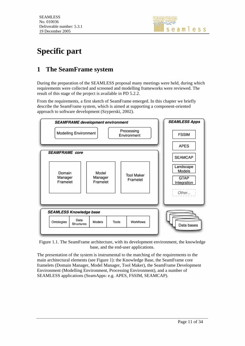
From the requirements, a first sketch of SeamFrame emerged. In this chapter we briefly describe the SeamFrame system, which is aimed at supporting a component-oriented approach to software development (Szyperski, 2002).
Figure 1.1. The SeamFrame architecture, with its development environment, the knowledge
base, and the end-user applications.
The presentation of the system is instrumental to the matching of the requirements to the main architectural elements (see Figure 1): the Knowledge Base, the SeamFrame core framelets (Domain Manager, Model Manager, Tool Maker), the SeamFrame Development Environment (Modelling Environment, Processing Environment), and a number of SEAMLESS applications (SeamApps: e.g. APES, FSSIM, SEAMCAP).

SEAMLESS No. 010036 Deliverable number: 5.3.1 19 December 2005
Page 13 of 34
2 The Knowledge Base
2.1 Purpose and goals
The Knowledge Base (KB) is a repository for arrays of information, from ontologies to data structures, from models to workflows and scenarios. Differently from the database, where SeamFrame-independent data are stored, the KB contains data elaborations which strictly depend on the SeamFrame architecture and functions.
The KB must contain Ontologies (for a definition, see Antoniou and Van Harmelen, 2004) of all the concepts used to model the agri-enviro-economic sector. The ontology must at least provide a controlled vocabulary and it describes the conceptual model adopted in SEAMLESS. The ontology will be represented using the standard OWL/RDFS languages. Adopting such language standards will pave the way to future interoperability with other frameworks and it will make possible the distribution of the SEAMLESS ontology on the web, in the spirit of collaboration with similar initiatives.
Ontologies also serve as a precious aid in browsing and querying a knowledge base, as they connect concepts in a meaningful way and lend themselves to powerful and intuitive forms of interactive graphical representation.
Building on the most recent advances in ontology-driven modelling and data mining (Villa, 2003; Michener, 2003; Ludaescher, 2001), we will employ the semantic characterisation of models and data to enable substitutability of components and data within models and analytical pipelines, automatic generation of transformations to enforce compatibility of storage type, units of measurement and mode and scale of representation, and definition of proper aggregation strategies.
The KB shall also contain instances of Data Structures, which represent views and aggregations of the concepts of the ontology, which become ‘fields’ of the data structures. These data structures, hereafter named Domain Classes, will provide an intermediate layer to the database. This part of the KB is called the Domain Base. Instances of Domain Classes, named Domain Objects, will provide access to ‘raw’ data contained in the data bases.
The KB will contain Models, both in binary format and declarative format. Models will be characterised by their inputs, states, outputs and parameters. Models will be searchable. This part of the KB is called the Model Base.
The KB will contain Tools, implemented as software components, that provide services such as numerical integration, data analyses, data visualisation, scenario optimisation and so on. All these software components communicate with models through a standard interface. This part of the KB is called the Toolbox.
The KB will contain Workflows, which are ordered sequence of operations performed by tools on models and data. Scenarios are instances of workflows. This part of the KB is called the Experiment Base.
2.2 User classes
The KB will be used by most users, through different layers.
SEAMLESS No. 010036 Deliverable number: 5.3.1 19 December 2005
Page 14 of 34
The Coders will create new data structures, organising Domain Classes in the Domain Base. Modellers will also create new models and store them in the Model Base, providing the appropriate ‘mark-up’ to later fetch the model.
Linkers will access the Model Base to retrieve basic models in order to build composite models.
Providers will access the KB to enter new information about data structures, data formats and so on.
Runners will access the Model Base to fetch models to execute and retrieve the data, via Domain Objects, instances of the Domain Classes, that are stored in the Domain Base, to feed the models during execution. The results will be stored as scenarios in the Experiment Base.
Players will run through prepared experiments (by the runners) to browse the results and explore alternatives.
Viewers will access the KB only indirectly, through a Reference Book kind of application.
2.3 Functions provided
The KB provides the following functions:
• store an ontology in OWL/RDFS format;
• store the specification of a domain class in a textual (XML) format;
• store domain objects in a relational database format;
• store the specification of a model in a declarative format;
• store a model implementation (binary code);
• store a tool implementation as a component (binary code);
• store a scenario specification (models + input data + parameters + tool parameters + tool selected + results).
SEAMLESS No. 010036 Deliverable number: 5.3.1 19 December 2005
Page 15 of 34
3 The Core
The SeamFrame Core is constituted by a set of co-operating classes and abstract interfaces:
• The Domain classes
• The Model classes
• The Tool interfaces and a set of components, which operate on these classes:
• the Domain Manager: provides software components that process the ontology and produce classes to be used in modelling (Domain Classes);
• the Model Manager: provides abstract classes open for implementation inheritance and a set of components able to perform transformations from model’s declarative code to imperative code;
• the Tool Maker: is a set of abstract interfaces to be implemented to deliver processing tool components operating on models and data.
3.1 Components
The Domain Manager framelet, the Model Manager framelet and the Tool Maker framelet provide components to be used in the development of SeamApps. Components are software units, which have the following advantages:
• Reusable: the practical possibility of using the component in different software systems; ease of use and solution to a common modelling problem are the key features.
• Replaceable: components can be replaced by others that have the same interface: e.g a new version of the same component, or a new independent implementation.
• Extensible: alternate processing capabilities can be added to the ones of the component from the user (i.e. the client), without needing to recompile the component (i.e. the server), and using the same interface.
3.2 Classes
SeamFrame Classes provide code which can be extended by the object-oriented programming concepts of inheritance and abstraction. Classes can still be packaged in components, offering a published interface. The main classes in SeamFrame are the Domain Class and the Model Class.
3.2.1 The Domain class
The Domain Class is a software class that specifies a Data Structure by aggregating various concepts of the ontology, i.e provides a specific ‘view’ of the ontology.
SEAMLESS No. 010036 Deliverable number: 5.3.1 19 December 2005
Page 16 of 34
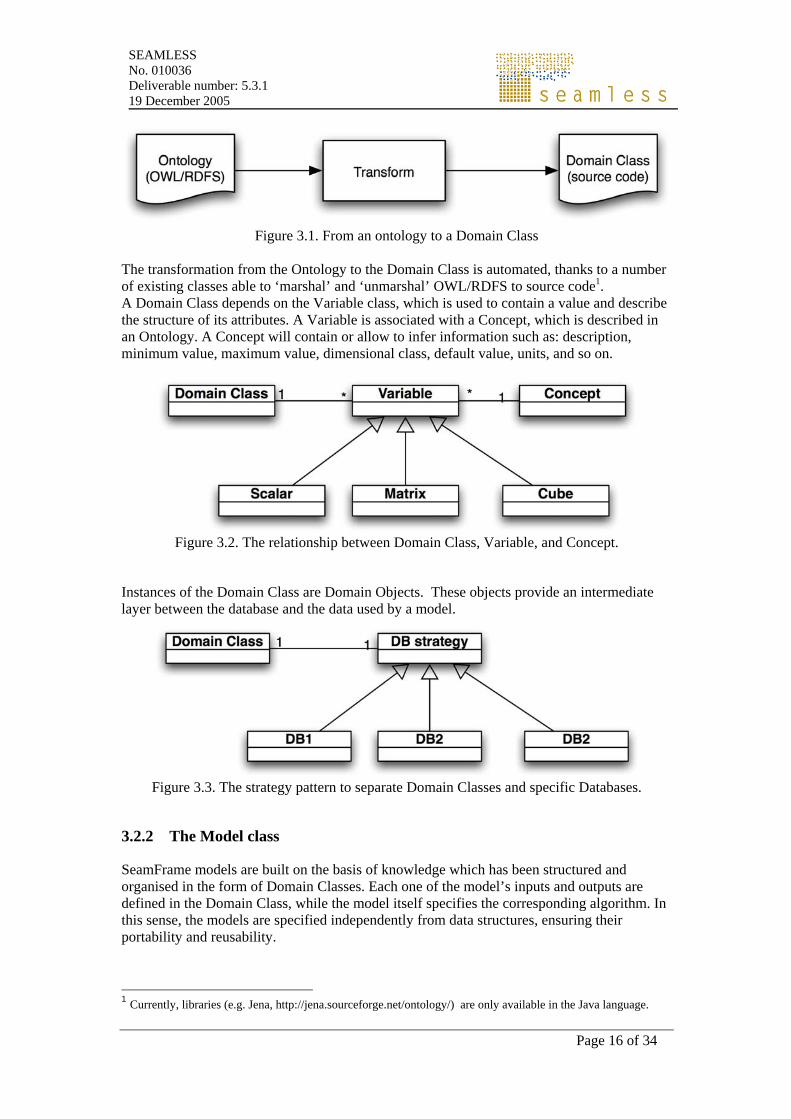
Figure 3.1. From an ontology to a Domain Class
The transformation from the Ontology to the Domain Class is automated, thanks to a number of existing classes able to ‘marshal’ and ‘unmarshal’ OWL/RDFS to source code1. A Domain Class depends on the Variable class, which is used to contain a value and describe the structure of its attributes. A Variable is associated with a Concept, which is described in an Ontology. A Concept will contain or allow to infer information such as: description, minimum value, maximum value, dimensional class, default value, units, and so on.
Figure 3.2. The relationship between Domain Class, Variable, and Concept.
Instances of the Domain Class are Domain Objects. These objects provide an intermediate layer between the database and the data used by a model.
Figure 3.3. The strategy pattern to separate Domain Classes and specific Databases.
3.2.2 The Model class
SeamFrame models are built on the basis of knowledge which has been structured and organised in the form of Domain Classes. Each one of the model’s inputs and outputs are defined in the Domain Class, while the model itself specifies the corresponding algorithm. In this sense, the models are specified independently from data structures, ensuring their portability and reusability.
1 Currently, libraries (e.g. Jena, http://jena.sourceforge.net/ontology/) are only available in the Java language.
SEAMLESS No. 010036 Deliverable number: 5.3.1 19 December 2005
Page 17 of 34
Also, the models will be accessible by a standard interface, which defines the model inputs and outputs.
Model inputs include exogenous inputs, control inputs, the state (for dynamic models), and parameter values.
The model outputs include the rate of change of the model state (for dynamic models) and any user defined transformation of the model states, inputs and parameters.
Models could be organised according to their various properties. So, we could categorise them as static and dynamic models (based on their equations), or as biophysical and economic models (according to their domain), or as point and distributed models (level of aggregation). However, from a software engineering point of view, we can distinguish two major categories of models in SeamFrame:
• Models implemented as black-box modules. These are the result of an imperative modelling process, i.e. they are implemented by a programmer following the standard SeamFrame interface.
• Models implemented as white-box modules. These are the result of a declarative modelling process, i.e. they are implemented by a modeller as a declarative structure defining the model in a high level representation.
Hint
A model in SeamFrame can be considered at three levels:
The conceptual level: The abstraction level, where concepts are connected to each other or transformed from one to another. In this level a model could be a set of equations or an algorithm. At this stage a model can be specified either using mathematical notation, or in an XML notation (e.g. MathML) in a declarative way.
The software level: The actual implementation of the equations/algorithm in source code (in Java, C#, etc.) A model at that stage is still manageable by editing the source code.
The binary level: The compiled sources of the software. At this stage software is able to be processed by a computer (to run). Its no longer editable in this form.
SEAMLESS No. 010036 Deliverable number: 5.3.1 19 December 2005
Page 18 of 34
3.3 The Domain Manager Framelet
3.3.1 Purpose and goals
The Domain Manager Framelet (DE) is part of the core of SeamFrame. It facilitates accessing the KB contents. DE provides the infrastructure for asserting ontologies, data, models, and experiments in the Knowledge Base. It is a common application programming interface (API) that will be used by the SeamFrame Development Environment (i.e. the Modelling Environment and the Processing Environment). The KB is manipulated using the DE, for creating, importing and/or editing the content of Knowledge Base. In this respect, DE exploits the meta-information on data and model structures in a reusable and extensible way.
3.3.2 User classes
The DE is a software library used by the SEAMFRAME Development Environment for managing data, models and experiments. Thus, it is not used directly by the users; rather it is invoked through the modelling and processing environments.
3.3.3 Functions provided
The DE functions provide an intermediate layer between the ‘semantically poor’ data stored in the database and the ‘semantically meaningful’ data structures to be used in the models. The mediating role is played by the Domain Classes.
Other significant functions of the DE include:
• The administration of the KB ontologies for the agro-environmental domain. Specifically, DE enables the creation of new ontologies, import of existing ones, and/or editing of those stored in the KB.
• Definition of new data structures in the KB (in the form of Domain Classes).
• Provide an inference engine that operates on the abstract concepts represented in data and models. The inference engine is able to perform simple logical reasoning tasks. For instance, it is possible to use the inference engine to assess compatibility of dependencies among models and to enforce the semantic consistency of data exchanged among models and workflows.
• Assisting the extension of Domain Objects for accessing the KB and retrieving data. DE supports the (automatic) construction of Domain Classes. The domain semantics is specified in a common and shared representation that is an integral part of SeamFrame. This ontology contains “universal” definitions of concepts in the agro-environmental domain. Even more, for various modelling domains (or even for a single model), the concepts describing inputs, outputs, states, rates, and parameters are structured in user-defined collections of concepts. The DE parses the ontology for creating the corresponding Domain Classes. Given the ontology (in RDFS/OWL format) as an input, the DE prepares generic-purpose Domain Class source code. The latter is ready to use for model building, through the Modelling Environment. Having the models constructed, at runtime DE creates the Domain Objects, i.e. instances of the Domain Classes for the specific experiment configuration (by the Processing Environment).
SEAMLESS No. 010036 Deliverable number: 5.3.1 19 December 2005
Page 19 of 34
3.4 The Model Manager Framelet
3.4.1 Purpose and scope of the Model Manager
The Model Manager delivers a set of tools, implemented as software components, that perform transformation operations to create the source code implementing a model starting from its declarative specification.
The Model Manager is capable of taking a declaratively-represented model as input and producing (for example): some type of description of the model (e.g. HTML); an executable version of the model; a transformation of the model (e.g. to simplify it, thus addressing the scaling problem).
The Model Manager provides tools for composition (aggregated models made from base models) in a declarative language.
The Model Manager provides interfaces to compilers in order to generate binary code from source code and/or declarative code.
3.4.2 User classes
Since the Model Manager is made of software components, it will be used by the coders and these components are made accessible to modellers and researchers in the Modelling Environment and the Processing Environment.
3.4.3 Functions provided
The Model Manager provides software components to:
• transform a declarative model into source code to be compiled;
• invoke compilation of models in source code;
• test model pre and post-conditions;
SEAMLESS No. 010036 Deliverable number: 5.3.1 19 December 2005
Page 20 of 34
3.5 The Tool Maker Framelet
3.5.1 Purpose and scope
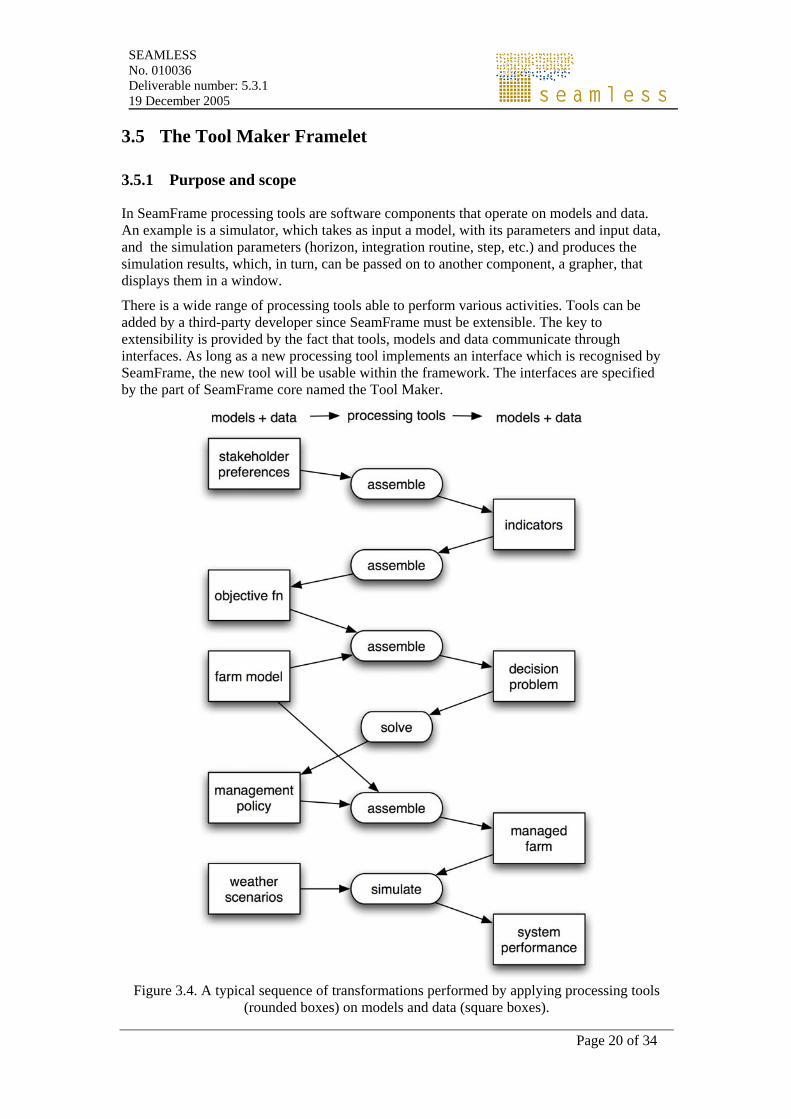
In SeamFrame processing tools are software components that operate on models and data. An example is a simulator, which takes as input a model, with its parameters and input data, and the simulation parameters (horizon, integration routine, step, etc.) and produces the simulation results, which, in turn, can be passed on to another component, a grapher, that displays them in a window.
There is a wide range of processing tools able to perform various activities. Tools can be added by a third-party developer since SeamFrame must be extensible. The key to extensibility is provided by the fact that tools, models and data communicate through interfaces. As long as a new processing tool implements an interface which is recognised by SeamFrame, the new tool will be usable within the framework. The interfaces are specified by the part of SeamFrame core named the Tool Maker.
Figure 3.4. A typical sequence of transformations performed by applying processing tools
(rounded boxes) on models and data (square boxes).
SEAMLESS No. 010036 Deliverable number: 5.3.1 19 December 2005
Page 21 of 34
3.5.2 User classes
Since processing tools are software components, they don’t have a user interface. They are used by the coders and they are made accessible to modellers and researchers in the Modelling Environment and the Processing Environment.
3.5.3 Functions provided
The most relevant to the delivery of a working prototype of SeamFrame are interfaces needed to implement the following tools: • simulation tool: it takes a model, with its parameters and data inputs, and a simulation
specification (time horizon, integration routine, etc.) and returns the simulation output.
• calibration tool: it takes a model where the parameters are not fixed, it also takes an objective function (which is a model), and the specification of the calibration algorithm to apply, and it returns a set of parameters for the model.
• data display tool: it takes a set of data and it returns a graphical object (dependent on the operating system) which presents the data in various formats: tables, maps, charts, etc..
• optimisation tool: it takes a model, with its parameters and data inputs, and objective function
• data processing tools: they convert, aggregate, dis-aggregate, interpolate, extrapolate data.

SEAMLESS No. 010036 Deliverable number: 5.3.1 19 December 2005
Page 23 of 34
4 The Development Environment
The SeamFrame Development Environment is composed of two main applications: the Modelling Environment and the Processing Environment. In the first application, the modeller can define and edit the data structures to be used within the model and s/he can then write a model, which will be then saved in the model base. In the Processing Environment models can be run, tested, optimised, the result visualised and all these operations can be structured for later re-play in work-flows.
4.1 The Modelling Environment
4.1.1 Purpose and goals
The modelling environment is a part of SeamFrame’s development environment. It aims to provide the users with all the appropriate infrastructure for building, retrieving and editing agro-environmental models of various types and scales, by exploiting the functionalities of the Domain Manager, the Model Manager and the Tool Maker of the SeamFrame core.
The Modelling environment will provide the infrastructures for developing both opaque and clear models. An opaque model is accessible only through its interface, while a clear model exposes its equations. The terms opaque and clear refer to the software interpretation and they do not have anything in common with the more usual terms of black and white box modeling. For instance, a white box model, which is a conceptual or process-based model where the causal relationships among variables are explicit, can be implemented as an opaque model component.
Development of opaque models: using the classes and components provided by Domain Manager and the Model Manager, a programmer will be able to use pre-formatted templates of a model. Based on these templates, written in source code, s/he will be “guided” to write the model’s code, compatible with the SeamFrame standard interface.
Development of clear models: through the Modelling Environment’s GUI a modeller will be enabled to define variables and parameters of a model using the ontology, specify the model algorithm in a declarative way (XML-based model-representation language) and finally, to create the complete source of the model, by the use of Model Manager facilities.
Thus, the Modelling Environment enables:
• substitutability of components and data within models and analytical pipelines,
• automatic generation of transformations to enforce compatibility of storage type, units of measurement and mode and scale of representation. This will be made possible thanks to the fact that model interfaces are semantically rich, so model composition will be facilitated by the application of such transformations,
• definition of proper aggregation strategies.
4.1.2 User classes
The main users of the ME are Coders and Linkers:
• Coders use the ME for accessing the KB, adding data tables and meta-data information (extracted from the ontologies)
SEAMLESS No. 010036 Deliverable number: 5.3.1 19 December 2005
Page 24 of 34
• Coders, which use DE and MB elements for building new models.
• Linkers also use MB elements to compose complex, structured models .
4.1.3 Functions provided
Through the Modelling Environment, the user interfaces transparently to functions provided by the Domain Manager, Model Manager and Tool Maker framelets to:
1. Introduce new Concepts in SF-ontology
2. Create new collections of ontology concepts, defining variables for a model.
3. Build models in a guided way, defining inputs/outputs/rates/states/parameters and algorithm, in a declarative or imperative way. This activity involves the association of models (built with Model Manager) to the concepts (defined in ontologies).
4. Retrieve, edit and store models in the Model Base.
5. Assemble models to create more complex and structured models, called composite models.
6. “Navigate” through data and model world, taking advantage of the rich semantics of both data and models. Both data and model structures are “tagged” with meta-information, (in XML format) that confronts with a generic ontology.
Building a composite model is enabled through the GUI of the Modeling environment. The user can assemble models together by linking the outputs of one model to the inputs of another. Consistency checks will be performed through the Domain Manager according to the ontological constraints and for validating the logic data and model meta-information. (i.e. the user will not be able to associate a model that needs as an input solar radiation at ground level with a data-table of extra-terrestrial solar radiation measurements).
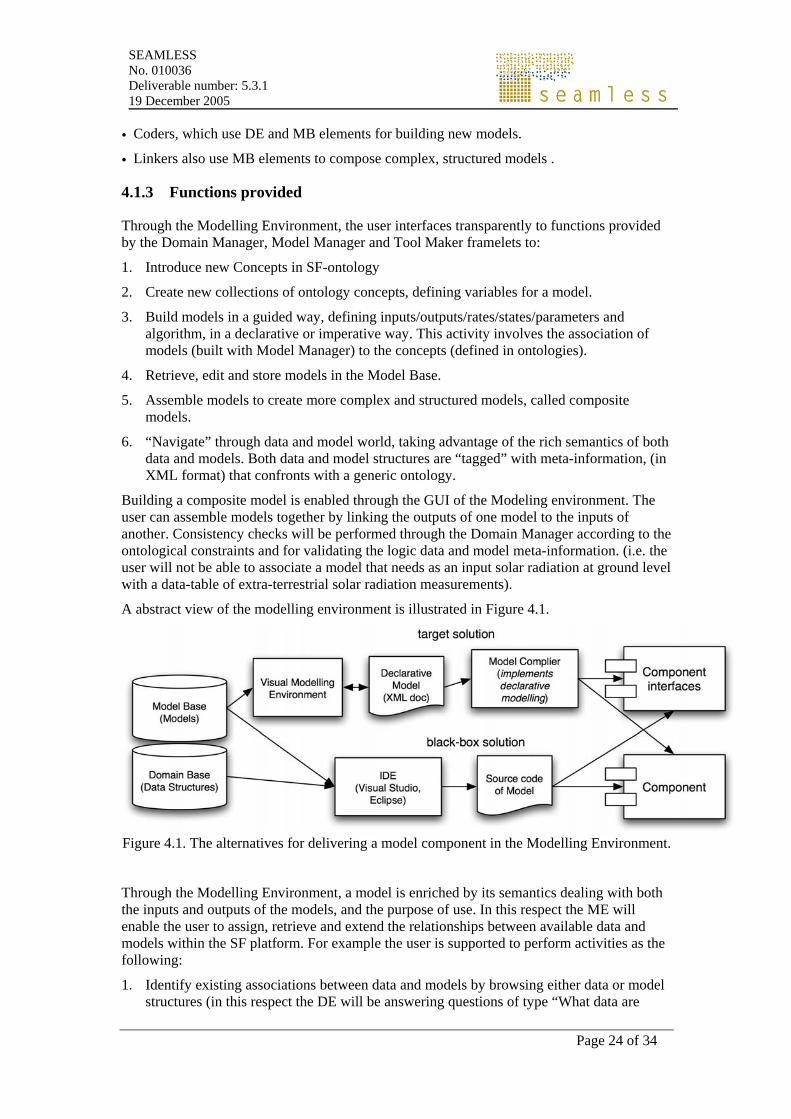
A abstract view of the modelling environment is illustrated in Figure 4.1.
Figure 4.1. The alternatives for delivering a model component in the Modelling Environment.
Through the Modelling Environment, a model is enriched by its semantics dealing with both the inputs and outputs of the models, and the purpose of use. In this respect the ME will enable the user to assign, retrieve and extend the relationships between available data and models within the SF platform. For example the user is supported to perform activities as the following:
1. Identify existing associations between data and models by browsing either data or model structures (in this respect the DE will be answering questions of type “What data are
SEAMLESS No. 010036 Deliverable number: 5.3.1 19 December 2005
Page 25 of 34
available for using the model M-1?” Or “Which models can be used on the dataset(s) available dealing with radiation in Athens?”
2. Set associations between data structures and models, which already exist in the SF database. (so the user can associate “Farm” with “Ferme”, “Campo”, or “Bauernhof” concepts, or the “Temp” input variable of a model with “T_in_C” column in a dataset).
3. Add new models and data tables in the Knowledge Base by defining their semantics (in this case the user can “add tags” to a model’s attributes (i.e. inputs-outputs-parameters-etc), or a data table added in the KB. For example the column “Income” in a table could refer to “average yearly income, measured on a given sample of 53 farms, expressed in Euros, in the Administrative Region of Languedoc-Roussillon in France ”. All these meta-information (quantity, time aggregation, sample size, measurement unit, spatial resolution) will be stored according to the ontology spoecifications.
SEAMLESS No. 010036 Deliverable number: 5.3.1 19 December 2005
Page 26 of 34
4.2 The Processing Environment
4.2.1 Purpose and scope
The Processing Environment is a software application built on top of SeamFrame. Its purpose is to let the user apply processing tools to models and data in order to perform the operations implemented by the tools.
The Processing Environment is designed adopting some key ideas of the OpenMI architecture (Brakkee et al. 2004).
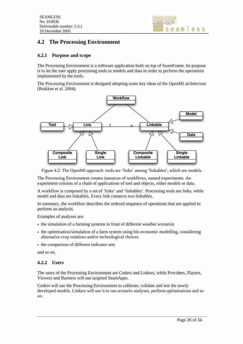
Figure 4.2. The OpenMI approach: tools are ‘links’ among ‘linkables’, which are models.
The Processing Environment creates instances of workflows, named experiments. An experiment consists of a chain of applications of tool and objects, either models or data.
A workflow is composed by a set of ‘links’ and ‘linkables’. Processing tools are links, while model and data are linkables. Every link connects two linkables.
In summary, the workflow describes the ordered sequence of operations that are applied to perform an analysis.
Examples of analyses are:
• the simulation of a farming systems in front of different weather scenarios
• the optimisation/simulation of a farm system using bio-economic modelling, considering alternative crop rotations and/or technological choices
• the comparison of different indicator sets and so on.
4.2.2 Users
The users of the Processing Environment are Coders and Linkers, while Providers, Players, Viewers and Runners will use targeted SeamApps.
Coders will use the Processing Environment to calibrate, validate and test the newly developed models. Linkers will use it to run scenario analyses, perform optimisations and so on.
SEAMLESS No. 010036 Deliverable number: 5.3.1 19 December 2005
Page 27 of 34
4.2.3 Functions provided
The functions provided by the Processing Environment are:
Prepare and run a calibration experiment:
• select a model, define the free parameters;
• select a calibration data set (this may require a preliminary set of data preparation);
• select a calibration tool and objective function (e.g. Least Squares, Maximum Likelihood, etc);
• create a data sink to store the calibration outputs;
• link the calibration tool to model and to the data sink;
• store the set of calibrated parameters; Prepare and run a simulation experiment:
• select a model
• instantiate the model for a given initial spatio-temporal location. This means to set the initial conditions
• select data feeds for exogenous inputs which might be open. This is the same to select an input scenario
• select a simulation tool and set the simulation parameters;
• run the simulation
• store the simulation results Other workflows may describe how to:
• Prepare and run an optimisation experiment;
• Prepare and run a scenario comparison experiment

SEAMLESS No. 010036 Deliverable number: 5.3.1 19 December 2005
Page 29 of 34
5 Applications
Building on SeamFrame, it will be possible to deliver applications targeting specific problems (SeamApps). In particular: APES, FSSIM, SEAMCAP, Landscape models and the integration of Seamless with GTAP. This is not a limited set, in the future it will be possible to develop and deliver other applications exploiting the features of SeamFrame.
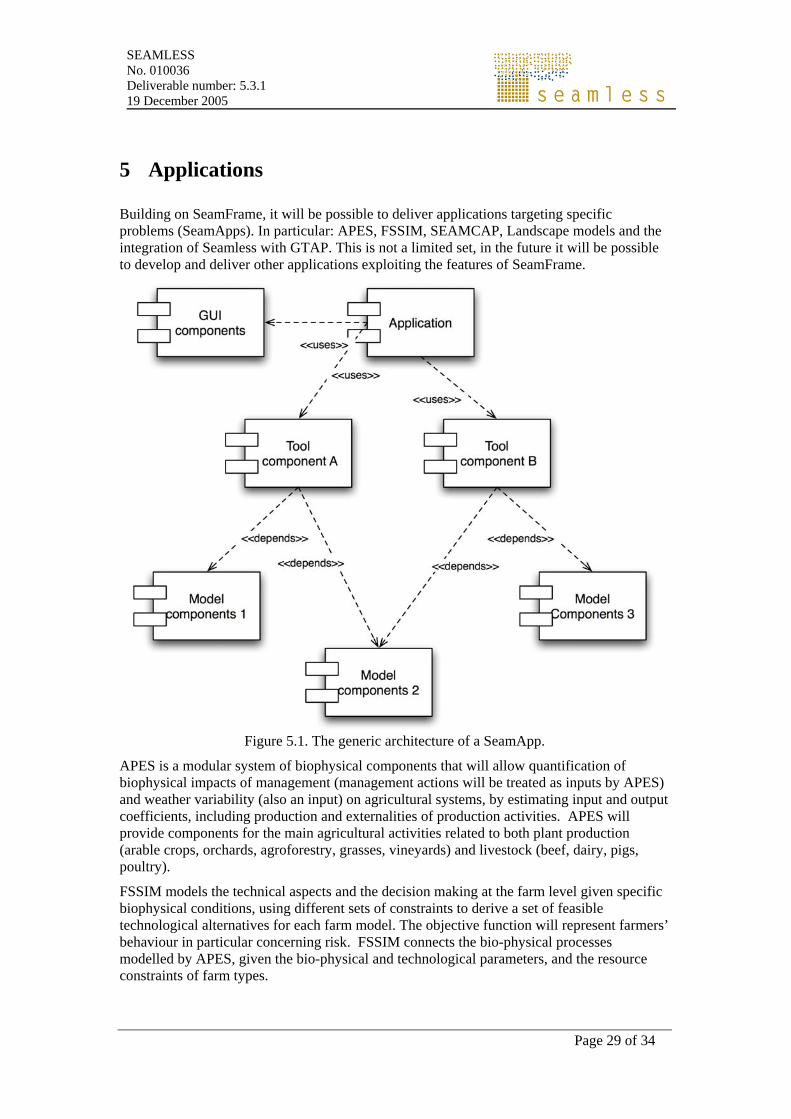
Figure 5.1. The generic architecture of a SeamApp.
APES is a modular system of biophysical components that will allow quantification of biophysical impacts of management (management actions will be treated as inputs by APES) and weather variability (also an input) on agricultural systems, by estimating input and output coefficients, including production and externalities of production activities. APES will provide components for the main agricultural activities related to both plant production (arable crops, orchards, agroforestry, grasses, vineyards) and livestock (beef, dairy, pigs, poultry).
FSSIM models the technical aspects and the decision making at the farm level given specific biophysical conditions, using different sets of constraints to derive a set of feasible technological alternatives for each farm model. The objective function will represent farmers’ behaviour in particular concerning risk. FSSIM connects the bio-physical processes modelled by APES, given the bio-physical and technological parameters, and the resource constraints of farm types.
SEAMLESS No. 010036 Deliverable number: 5.3.1 19 December 2005
Page 30 of 34
SEAMCAP is a re-factoring of parts of the CAPRI model, on the basis of the SeamFrame architecture and design principles.
Landscape models will allow to quantitatively or visually assess changes in land use due to the consequences of the application of new policies and conditions. The interplay of SEAMCAP and FSSIM will produce a series of results which will provide the inputs to specialized landscape models that, in turn, help to study landscape spatial patterns and landscape dynamics, and to test hypotheses related to environmental or ecological objectives.
GTAP will also be integrated in SEAMLESS, even if not as tightly as CAPRI. The integration will happen at the data level, in order to allow agricultural policies, designed with SEAMCAP, to be inserted in the global economic model described by means of GTAP.
SEAMLESS No. 010036 Deliverable number: 5.3.1 19 December 2005
Page 31 of 34
References
Antoniou, G., Van Harmelen, F. 2004. A Semantic Web Primer. The MIT Press, Boston.
Brakkee, Brinkman, Gergersen, Hummel, Westen et al. 2004. HamronIT Document Series Part C – the org.OpenMI.Standard interface specification. The HarmonIT Document Series, IT Frameworks (HarmonIT) Contract EVK1-CT-2001-00090.
Szyperski, C., Gruntz, D., Murer, S. 2002. Component Software: Beyond Object-Oriented Programming, 2nd Edition. ACM Press, New York.
Ludaescher, B., Gupta, A., and Martone, M.E. 2001. Model-based mediation with Domain Maps. In: Proceedings of 17th Intl. Conference on Data Engineering (ICDE), Heidelberg, Germany, IEEE Computer Society.
Pasetti, A. 2002. Software Frameworks and Embedded Control Systems. Lecture Notes in Computer Science, 2231. Springer Verlag, Berlin.
Villa, F. 2001. Integrating modelling architecture: a declarative framework for multi-paradigm, multi-scale ecological modelling. Ecological Modelling 137, 23-42.

SEAMLESS No. 010036 Deliverable number: 5.3.1 19 December 2005
Page 33 of 34
Glossary
Application: it is a software package obtained from the modelling environment. An application includes a custom GUI and it includes several components.
Architecture: Blue-print and styles to define structure;
Attribute: a property of a instance of a real world concept;
Clear models. See Opaque models.
Component: it is a model of a physical piece of the system being built. For example, source code files, DLL's, Java beans and other discrete pieces of the system may be represented as components. By building the system in discrete components, localisation of data and behaviour allows for decreased dependency between classes and objects, providing a more robust and maintainable design. Components may be either models or tools/utilities.
Component: replaceable unit, encapsulating design decisions, as part of larger unit;
Conceptual model: describing (relevant) aspects of the real world in a functional context.
Conceptualization: Making (usually) a graphical representation of a model, a scenario, processes etc, for improved and joint understanding.
Declarative code: computer code where the order of the statements is not relevant for its execution. Declarative code contains the model equations, but it does not tell how to compute a result using the equations. Modelling is an activity well suited to be described with declarative code.
Domain Class: it is an object-oriented data structure used to structure and organize modeling knowledge. A Domain Class is a partial view of an ontology, where the boundaries of the data structure have been defined.
Domain Object: it is an instance of the Domain Class, where the attributes take specific values.
Experiment: in the context of SeamFrame an Experiment defines all the information related to a simulation or an optimization run. This includes the data used as inputs, the model parameters, the simulation parameters (horizon, time step, etc). If the Experiment has been performed, it also contains links to the results.
Framelet: analogous to a subsystem in an application. The complexity of a framework is broken up into framelets. A framelet is a cluster of related abstract interfaces and design patterns.
Framework: productivity tool(box) to assemble components using architecture.
Imperative code: computer code that explains how to solve a problem, following a unambiguous and definite sequence of steps. Imperative code processes declarative code. Simulation is an activity which requires imperative code.
Indicators: outputs of either static or dynamic models which allow evaluating system performance.
Inheritance: in object-oriented programming inheritance is the property that allows a data type which inherits from another data type to include all its attributes without the need for their redefinition.
SEAMLESS No. 010036 Deliverable number: 5.3.1 19 December 2005
Page 34 of 34
Integrated framework: an application which allows the evaluation of agricultural systems accounting for technical, environmental, economic and social indicators. One or more integrated frameworks will be the main deliverables of the integrated project.
Model: focused simplification of (a phenomena or process in) the real world;
Modelling environment: a software which allows developing components and applications. The modelling environments contains components which include a GUI for either component or application development
Modelling framework: the kernel component for static and dynamic model components use.
Ontology: it is a specification of a conceptualisation. Once a modeling exercise has defined all the variables and relationships existing in a given model, this information can be stored in an ontology. There are many languages which can be used to represent an ontology, but RDFS/OWL is one of the most common since, being based on XML, it can be easily processed by computers.
Opaque vs clear models: while models can be white (the equations are based on a conceptual representation of the physical processes) or black (the equations are derived from data and they do not explicitly represent physical phenomena), their implementations can be opaque (the model is implemented as a component and its internal structure is not accessible) or clear (the model is implemented as a class, and the internal codde structure is visible and accessible).
Project: when referred in the use cases of the user Application/component developer (see below) a project is either a component or a system model which includes several components. When the user is a farmer or a policy maker, a project is the use of an application in specific conditions (a farm, a region etc.)
Programming interface: a set of component interfaces, packaged in a binary object together with their implementations, with the necessary documentation to reuse them in a software application.
Simulation: monitoring dynamics of attributes (in time and/or in space);
Software framework: see Framework.
Source: a source produces the value of an attribute;
System: a portion of the real world, with clearly defined borders, described both in a static and dynamic fashion by models