Embed Size (px)
Citation preview
http://loa.ensta.fr/ UMR 7639
A nonlinear envelope equation for ultrashort pulse
propagation in guided structures.
Comparison with experimental results
http://loa.ensta.fr/ UMR 7639
C.L. Arnold1, S. Akturk1,2, B. Zhou1, M. Franco1,A.Couairon3 and A. Mysyrowicz1
1 Laboratoire d’Optique Appliquée, École Nationale Supérieure des Techniques Avancées - École Polytechnique, Palaiseau, France
2 Department of Physics, Istanbul Technical University, Maslak 34469 Istanbul, Turkey
3 Centre de Physique Théorique, CNRS, École Polytechnique, Palaiseau, France
Palaiseau - FRANCE
http://loa.ensta.fr/ UMR 7639
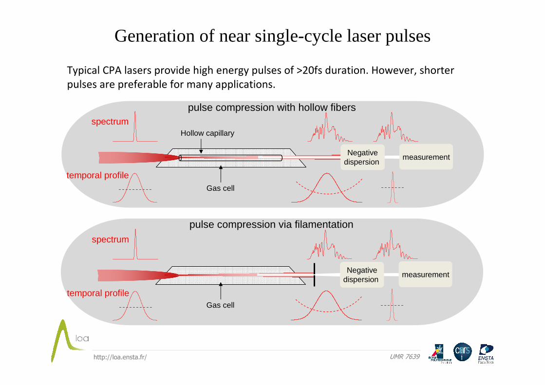
Generation of near single-cycle laser pulses
Typical CPA lasers provide high energy pulses of >20fs duration. However, shorter
pulses are preferable for many applications.
Negativedispersion
Hollow capillary
measurement
spectrum
temporal profile
pulse compression with hollow fibers
Gas cell
Negativedispersion
measurement
pulse compression via filamentation
spectrum
temporal profileGas cell
http://loa.ensta.fr/ UMR 7639
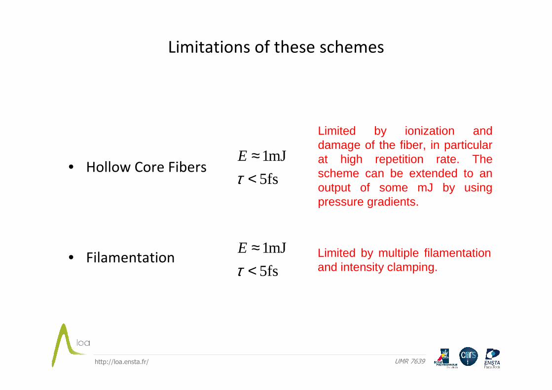
Limitations of these schemes
• Hollow Core Fibers
• Filamentation
5fs
mJ1
<≈
τE
5fs
mJ1
<≈
τE
Limited by ionization and damage of the fiber, in particular at high repetition rate. The scheme can be extended to an output of some mJ by using pressure gradients.
Limited by multiple filamentationand intensity clamping.
http://loa.ensta.fr/ UMR 7639
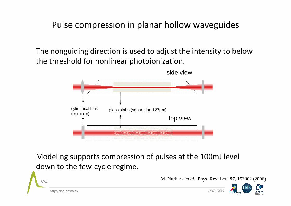
Pulse compression in planar hollow waveguides
The nonguiding direction is used to adjust the intensity to below
the threshold for nonlinear photoionization.
Modeling supports compression of pulses at the 100mJ level
down to the few-cycle regime.
side view
top view
glass slabs (separation 127µm)cylindrical lens (or mirror)
M. Nurhuda et al., Phys. Rev. Lett. 97, 153902 (2006)
http://loa.ensta.fr/ UMR 7639
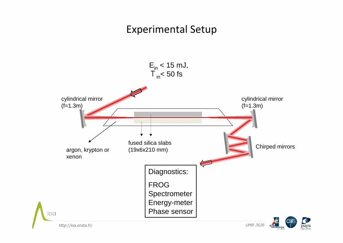
Experimental Setup
fused silica slabs(19x6x210 mm)
Ein < 15 mJ, Τin< 50 fs
cylindrical mirror (f=1.3m)
cylindrical mirror (f=1.3m)
argon, krypton or xenon
Chirped mirrors
Diagnostics:
FROGSpectrometerEnergy-meterPhase sensor
http://loa.ensta.fr/ UMR 7639
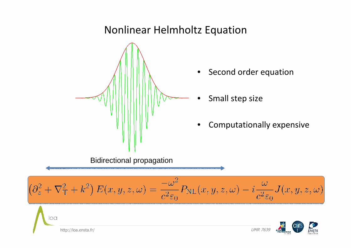
Nonlinear Helmholtz Equation
• Second order equation
• Small step size
• Computationally expensive
Bidirectional propagation
http://loa.ensta.fr/ UMR 7639
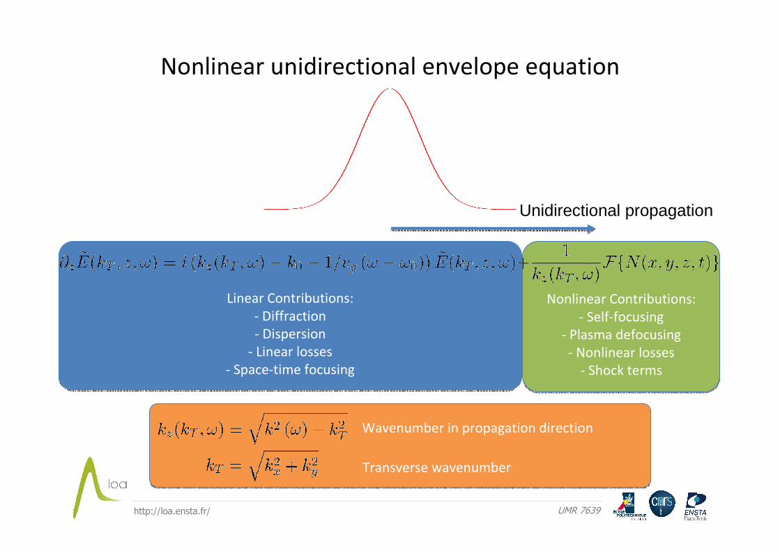
Nonlinear unidirectional envelope equation
Nonlinear Contributions:
- Self-focusing
- Plasma defocusing
- Nonlinear losses
- Shock terms
Nonlinear Contributions:
- Self-focusing
- Plasma defocusing
- Nonlinear losses
- Shock terms
Linear Contributions:
- Diffraction
- Dispersion
- Linear losses
- Space-time focusing
Linear Contributions:
- Diffraction
- Dispersion
- Linear losses
- Space-time focusing
Wavenumber in propagation direction
Transverse wavenumber
Unidirectional propagation
http://loa.ensta.fr/ UMR 7639
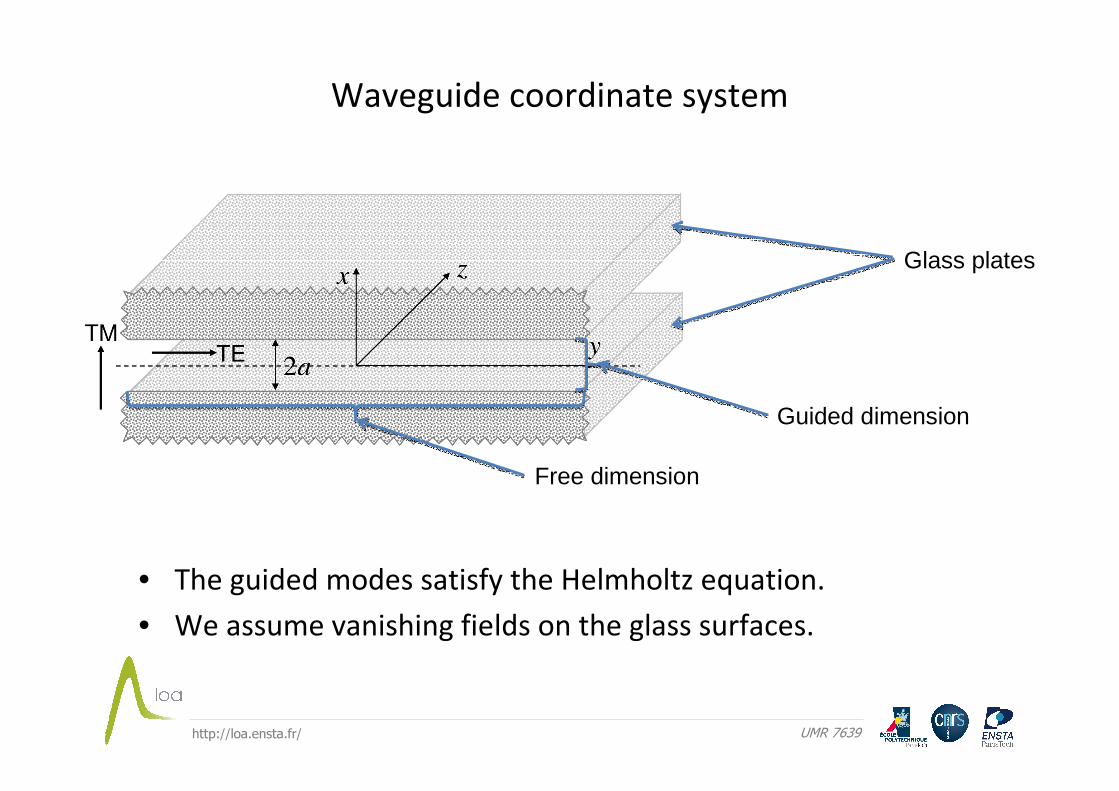
Glass plates
Guided dimension
Free dimension
Waveguide coordinate system
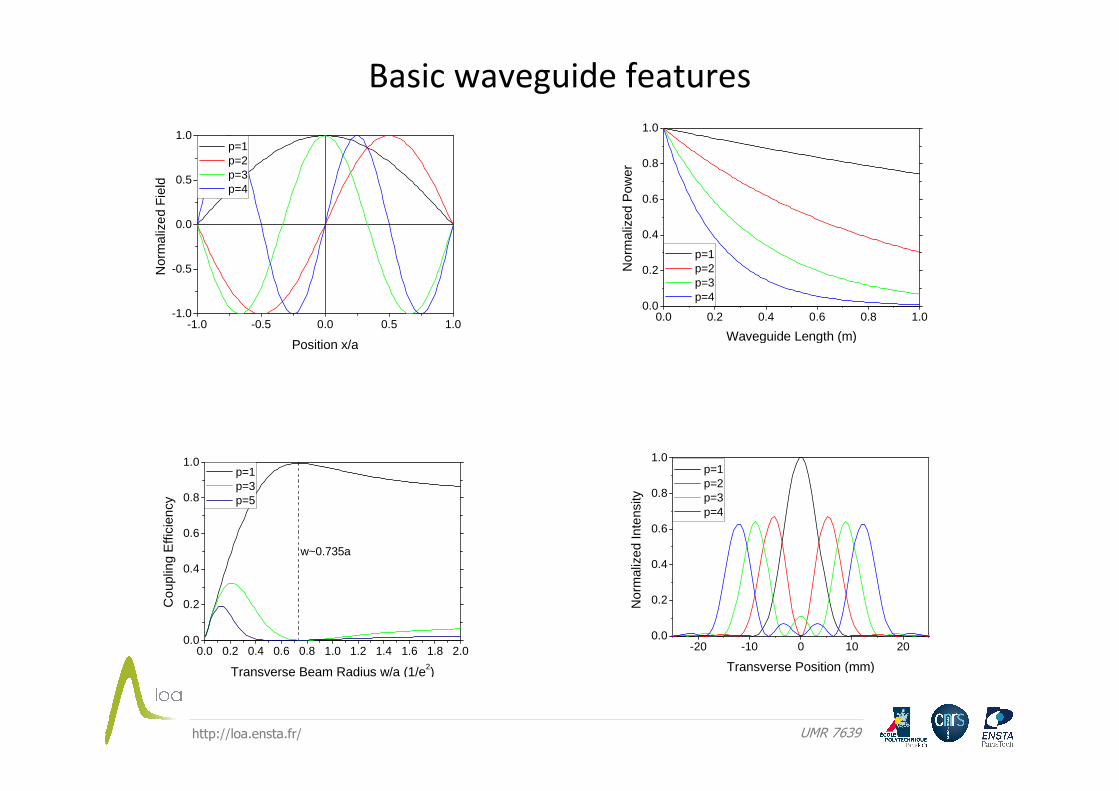
• The guided modes satisfy the Helmholtz equation.
• We assume vanishing fields on the glass surfaces.
http://loa.ensta.fr/ UMR 7639
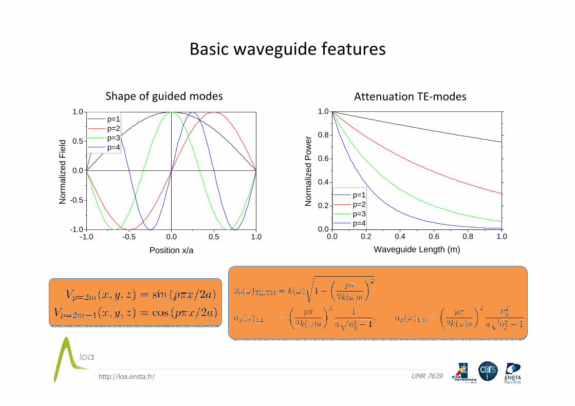
-1.0 -0.5 0.0 0.5 1.0-1.0
-0.5
0.0
0.5
1.0
Nor
mal
ized
Fie
ld
Position x/a
p=1 p=2 p=3 p=4
0.0 0.2 0.4 0.6 0.8 1.00.0
0.2
0.4
0.6
0.8
1.0
Nor
mal
ized
Pow
er
Waveguide Length (m)
p=1 p=2 p=3 p=4
Shape of guided modes Attenuation TE-modes
Basic waveguide features
http://loa.ensta.fr/ UMR 7639
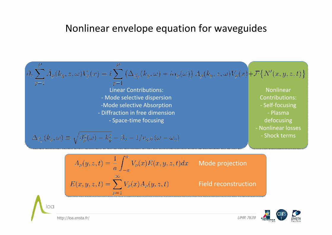
Nonlinear
Contributions:
- Self-focusing
- Plasma
defocusing
- Nonlinear losses
- Shock terms
Nonlinear
Contributions:
- Self-focusing
- Plasma
defocusing
- Nonlinear losses
- Shock terms
Linear Contributions:
- Mode selective dispersion
-Mode selective Absorption
- Diffraction in free dimension
- Space-time focusing
Linear Contributions:
- Mode selective dispersion
-Mode selective Absorption
- Diffraction in free dimension
- Space-time focusing
Nonlinear envelope equation for waveguides
Mode projection
Field reconstruction
http://loa.ensta.fr/ UMR 7639
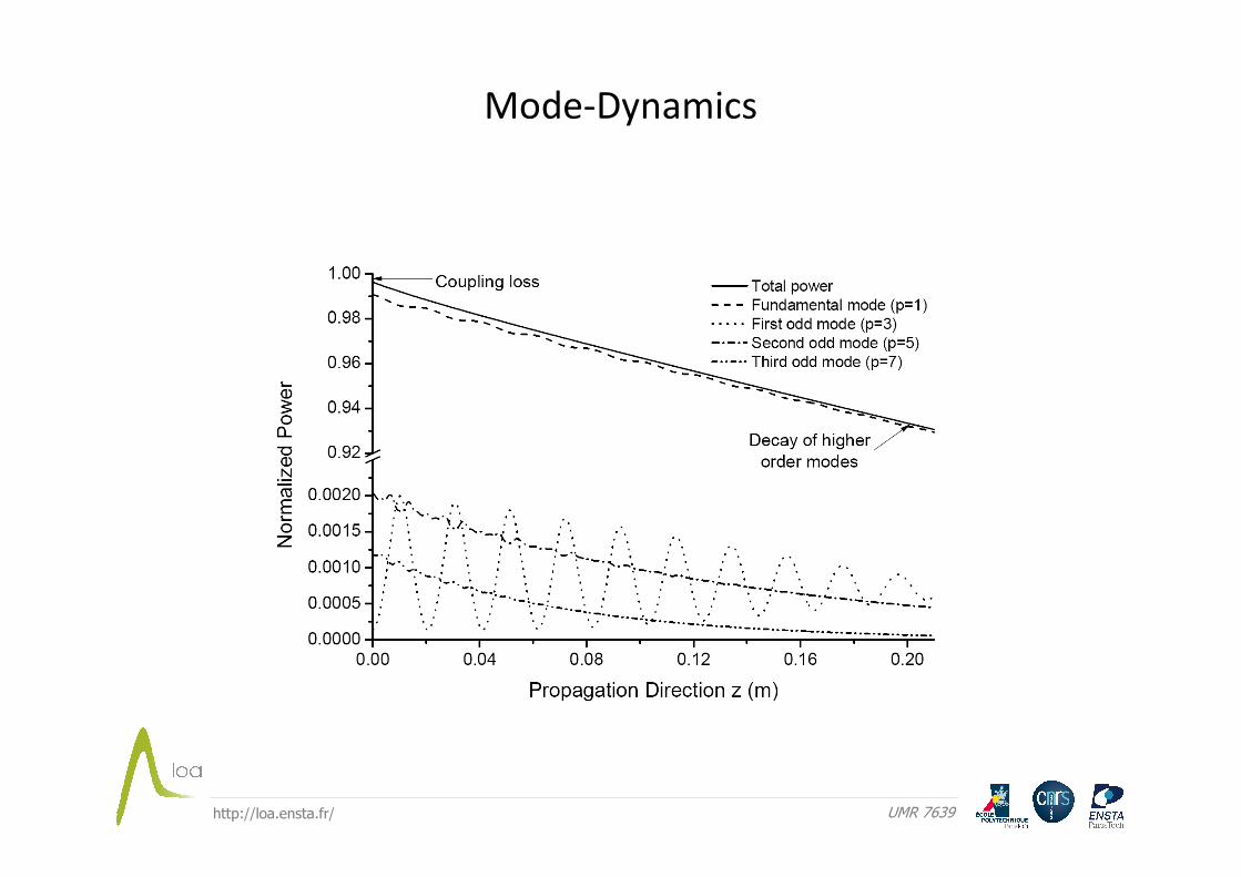
Mode-Dynamics
http://loa.ensta.fr/ UMR 7639
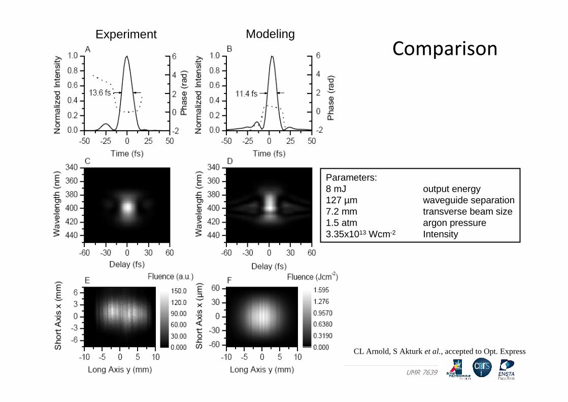
Experiment Modeling
Parameters:8 mJ output energy127 µm waveguide separation7.2 mm transverse beam size1.5 atm argon pressure3.35x1013 Wcm-2 Intensity
Comparison
CL Arnold, S Akturk et al., accepted to Opt. Express
http://loa.ensta.fr/ UMR 7639
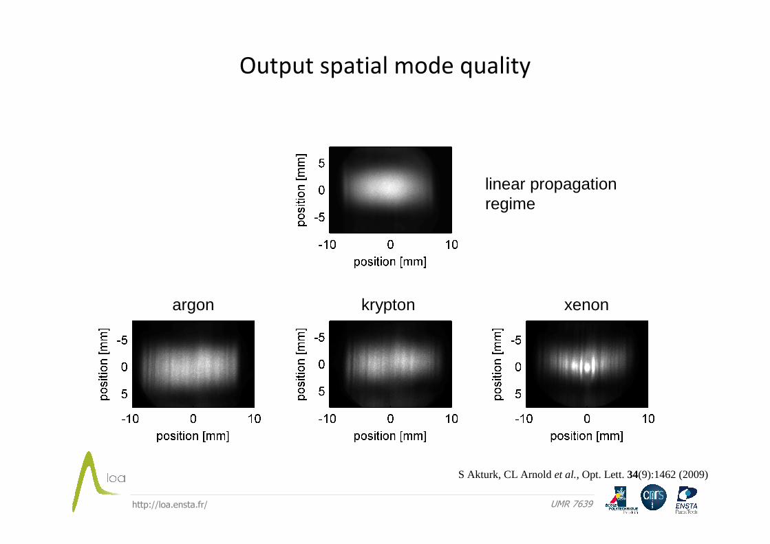
Output spatial mode quality
linear propagation regime
argon krypton xenon
S Akturk, CL Arnold et al., Opt. Lett. 34(9):1462 (2009)
http://loa.ensta.fr/ UMR 7639
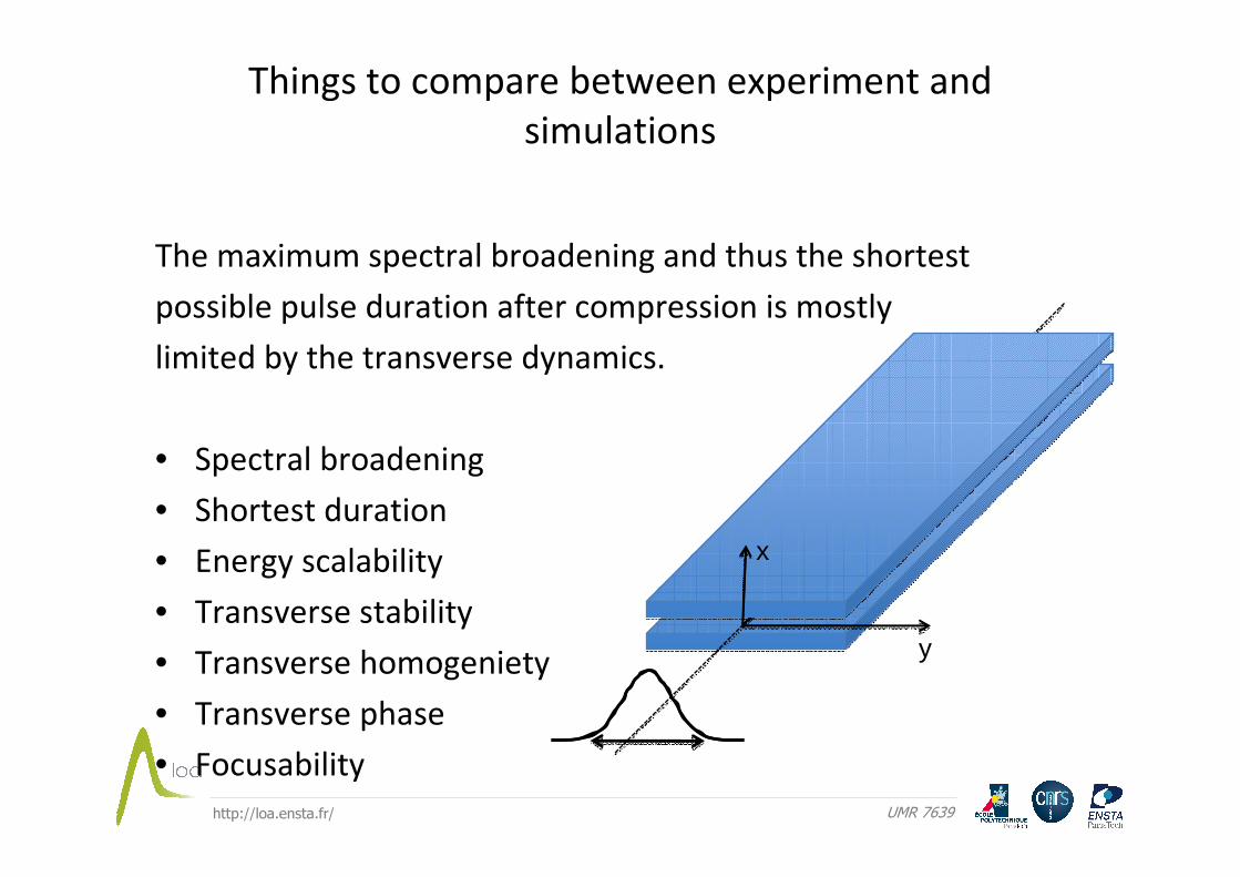
The maximum spectral broadening and thus the shortest
possible pulse duration after compression is mostly
limited by the transverse dynamics.
• Spectral broadening
• Shortest duration
• Energy scalability
• Transverse stability
• Transverse homogeniety
• Transverse phase
• Focusability
Things to compare between experiment and
simulations
z
y
x
http://loa.ensta.fr/ UMR 7639
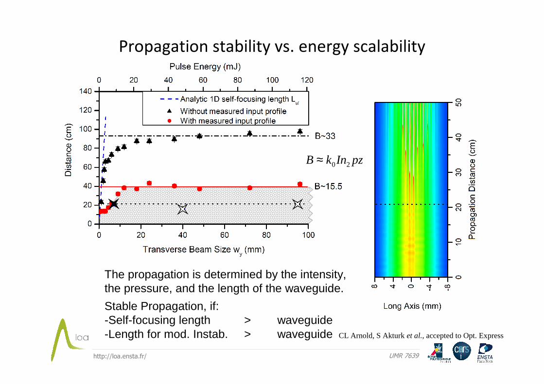
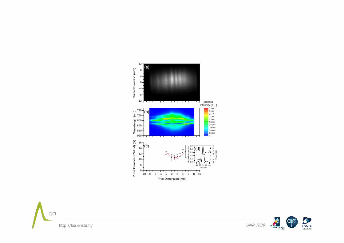
Propagation stability vs. energy scalability
The propagation is determined by the intensity,the pressure, and the length of the waveguide.
Stable Propagation, if:-Self-focusing length > waveguide-Length for mod. Instab. > waveguide
pzInkB 20≈
CL Arnold, S Akturk et al., accepted to Opt. Express
http://loa.ensta.fr/ UMR 7639
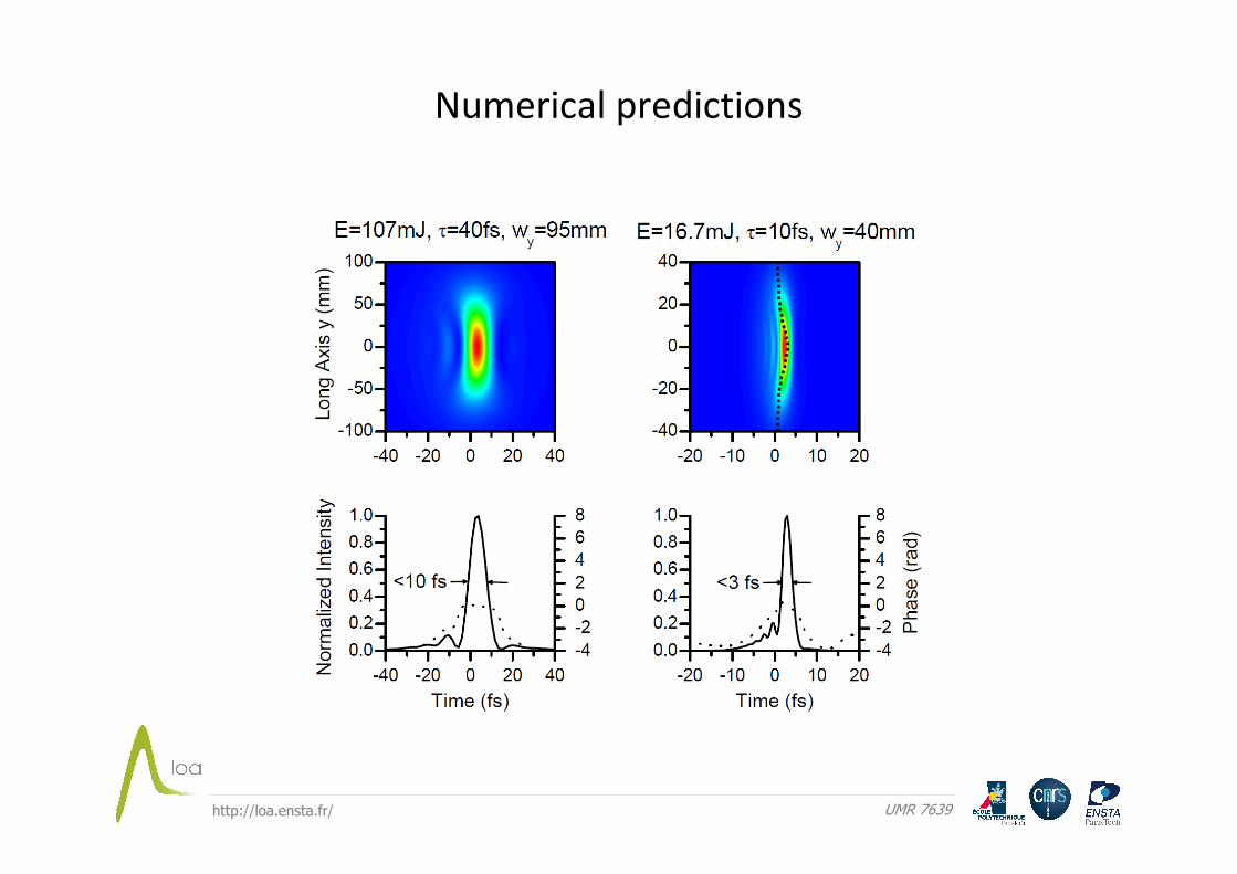
Numerical predictions
http://loa.ensta.fr/ UMR 7639
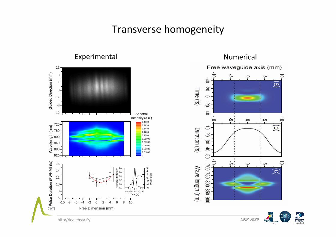
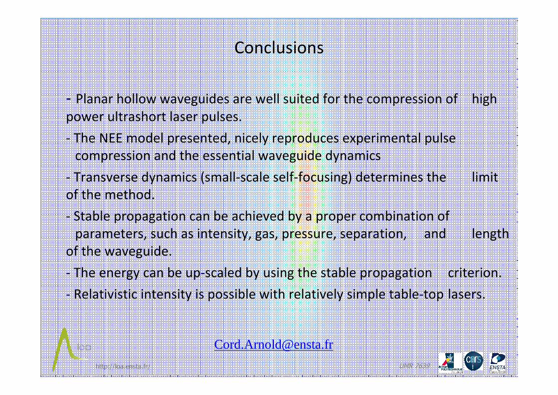
Transverse homogeneity
-10 -8 -6 -4 -2 0 2 4 6 8 106
8
10
12
14
16
920
880
840
800
760
720
Wav
elen
gth
(nm
)
0
0.01800
0.03600
0.05400
0.07200
0.09000
0.1080
0.1260
0.1440
0.1620
0.1800
SpectralIntensity (a.u.)
-12
-8
-4
0
4
8
12
Gui
ded
Dire
ctio
n (m
m)
Pul
se D
urat
ion
(FW
HM
) (f
s)
Free Dimension (mm)
-40 -20 0 20 40
0.0
0.2
0.4
0.6
0.8
1.0
Nor
mal
ized
Inte
nsity
Time (fs)
-6-4-20246
Pha
se (
rad)
Experimental Numerical
http://loa.ensta.fr/ UMR 7639
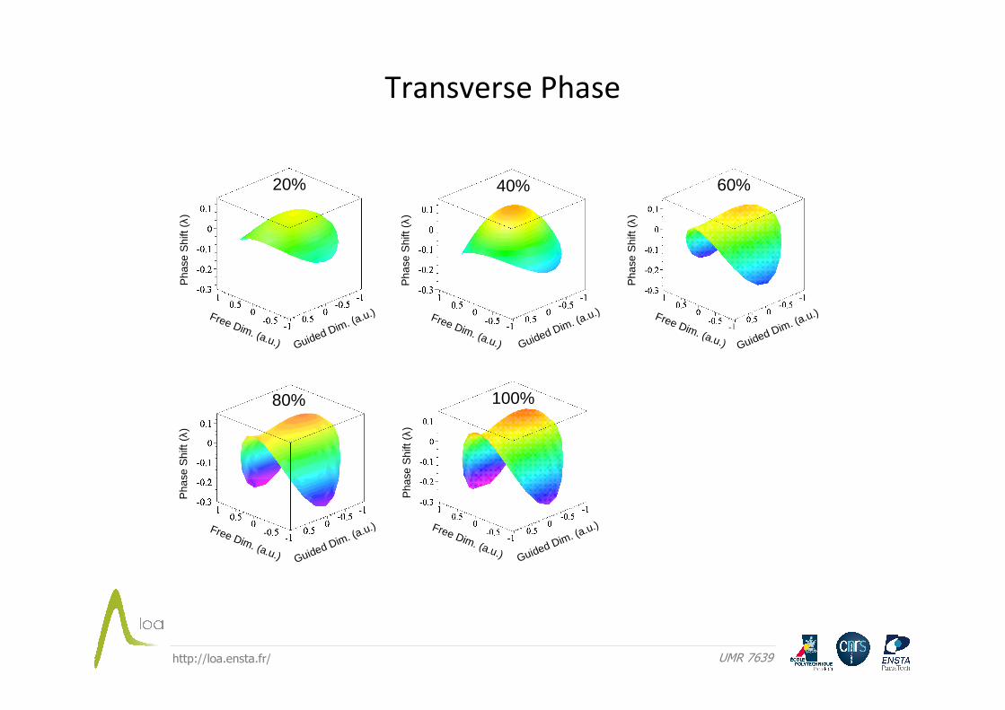
Free Dim. (a.u.) Guided Dim. (a.u.)
Pha
se S
hift
(λ)
20%
Pha
se S
hift
(λ)
Free Dim. (a.u.) Guided Dim. (a.u.)
40%
Pha
se S
hift
(λ)
Free Dim. (a.u.) Guided Dim. (a.u.)
60%P
hase
Shi
ft (λ
)
Free Dim. (a.u.) Guided Dim. (a.u.)
80%P
hase
Shi
ft (λ
)
Free Dim. (a.u.) Guided Dim. (a.u.)
100%
Transverse Phase
http://loa.ensta.fr/ UMR 7639
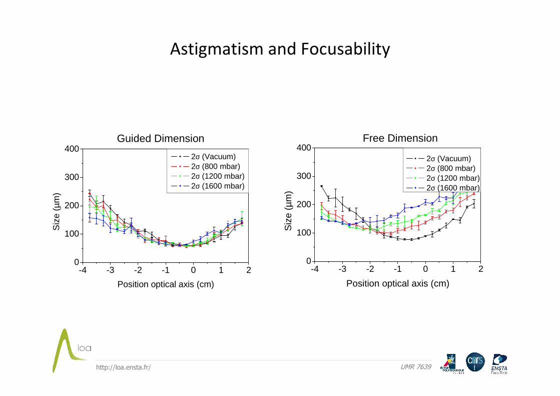
Guided Dimension Free Dimension
-4 -3 -2 -1 0 1 20
100
200
300
400 2σ (Vacuum) 2σ (800 mbar) 2σ (1200 mbar) 2σ (1600 mbar)
Siz
e (µ
m)
Position optical axis (cm)
-4 -3 -2 -1 0 1 20
100
200
300
400
Siz
e (µ
m)
Position optical axis (cm)
2σ (Vacuum) 2σ (800 mbar) 2σ (1200 mbar) 2σ (1600 mbar)
Astigmatism and Focusability
http://loa.ensta.fr/ UMR 7639
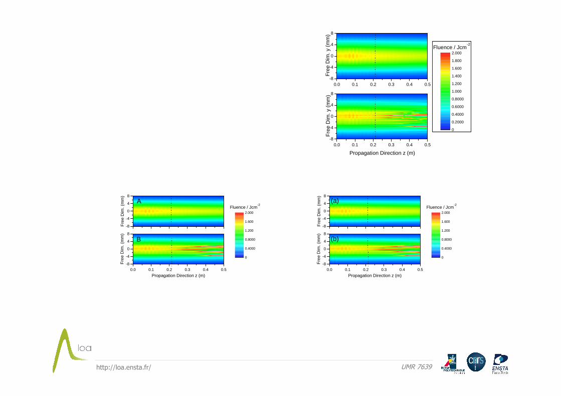
-200-100
0100200
Fre
e ax
is (
µm) z=95cm z=96cm z=97cm
-200-100
0100200
z=98cm
Fre
e ax
is (
µm) z=99cm
-50 -25 0 25 50 Time (fs)
z=100cm
-50 -25 0 25 50
-200-100
0100200
z=101cm
Time (fs)
Fre
e ax
is (
µm)
-50 -25 0 25 50
z=102cm
Time (fs)90 95 100 105 110
-200-100
0100200
Position opt. axis (cm)
Fre
e ax
is (
µm)
-200-100
0100200
Fre
e ax
is (
µm) z=95cm z=96cm z=97cm
-200-100
0100200
z=98cm
Fre
e ax
is (
µm) z=99cm
-50 -25 0 25 50 Time (fs)
z=100cm
-50 -25 0 25 50
-200-100
0100200
z=101cm
Time (fs)F
ree
axis
(µm
)
-50 -25 0 25 50
z=102cm
Time (fs)90 95 100 105 110
-200-100
0100200
Position opt. axis (cm)
Fre
e ax
is (
µm)
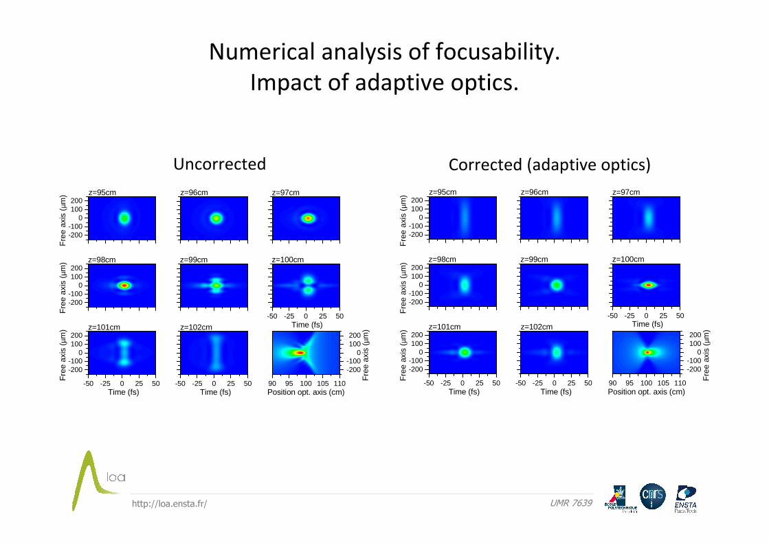
Numerical analysis of focusability.
Impact of adaptive optics.
Uncorrected Corrected (adaptive optics)
http://loa.ensta.fr/ UMR 7639
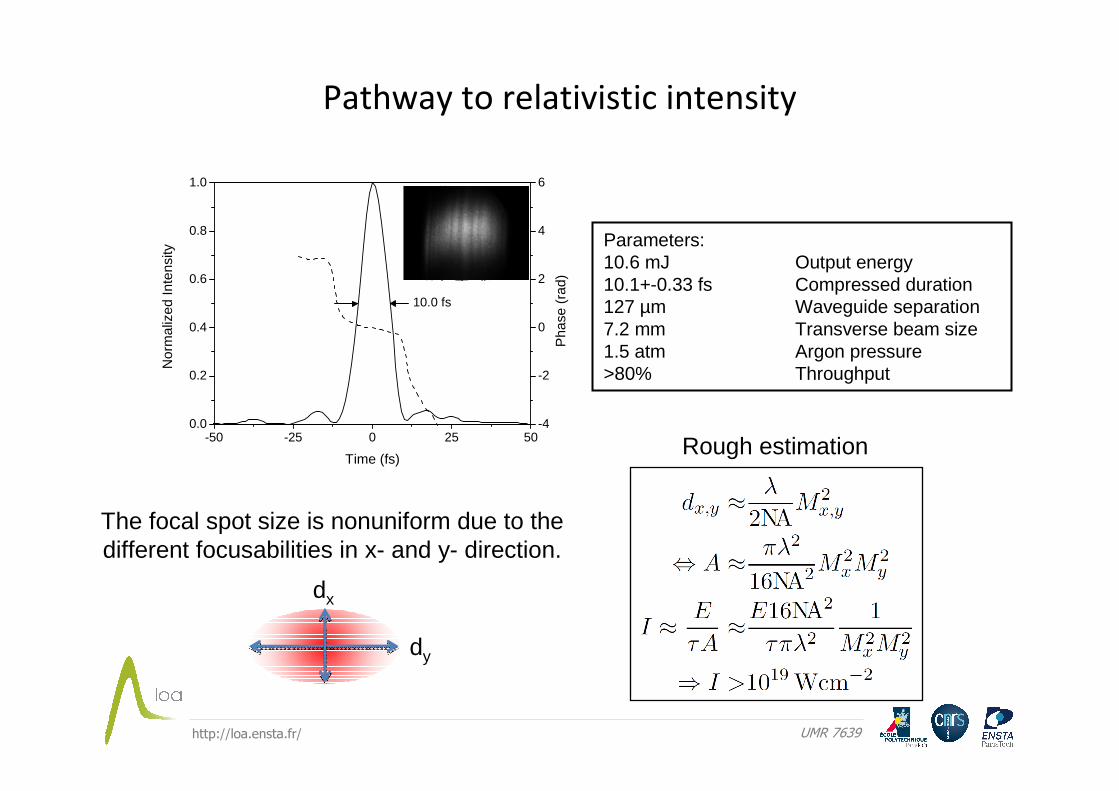
-50 -25 0 25 500.0
0.2
0.4
0.6
0.8
1.0N
orm
aliz
ed In
tens
ity
Time (fs)
-4
-2
0
2
4
6
Pha
se (
rad)
10.0 fs
Pathway to relativistic intensity
dy
dx
Parameters:10.6 mJ Output energy10.1+-0.33 fs Compressed duration127 µm Waveguide separation7.2 mm Transverse beam size1.5 atm Argon pressure>80% Throughput
Rough estimation
The focal spot size is nonuniform due to the different focusabilities in x- and y- direction.
http://loa.ensta.fr/ UMR 7639
- Planar hollow waveguides are well suited for the compression of high
power ultrashort laser pulses.
- The NEE model presented, nicely reproduces experimental pulse
compression and the essential waveguide dynamics
- Transverse dynamics (small-scale self-focusing) determines the limit
of the method.
- Stable propagation can be achieved by a proper combination of
parameters, such as intensity, gas, pressure, separation, and length
of the waveguide.
- The energy can be up-scaled by using the stable propagation criterion.
- Relativistic intensity is possible with relatively simple table-top lasers.
Conclusions
http://loa.ensta.fr/ UMR 7639
http://loa.ensta.fr/ UMR 7639
-10 -8 -6 -4 -2 0 2 4 6 8 106
8
10
12
14
16
920
880
840
800
760
720
Wav
elen
gth
(nm
)0
0.01800
0.03600
0.05400
0.07200
0.09000
0.1080
0.1260
0.1440
0.1620
0.1800
SpectralIntensity (a.u.)
-12
-8
-4
0
4
8
12
Gui
ded
Dire
ctio
n (m
m)
Pul
se D
urat
ion
(FW
HM
) (f
s)
Free Dimension (mm)
-40 -20 0 20 40
0.0
0.2
0.4
0.6
0.8
1.0
Nor
mal
ized
Inte
nsity
Time (fs)
-6-4-20246
Pha
se (
rad)
(a)
(b)
(c)(d)
http://loa.ensta.fr/ UMR 7639
-8
-4
0
4
8
Fre
e D
im. (
mm
)
Fluence / Jcm-2
0.0 0.1 0.2 0.3 0.4 0.5-8
-4
0
4
8
Propagation Direction z (m)
Fre
e D
im. (
mm
)
0
0.4000
0.8000
1.200
1.600
2.000
0.0 0.1 0.2 0.3 0.4 0.5-8
-4
0
4
8
Fre
e D
im. y
(m
m)
Fluence / Jcm-2
0.0 0.1 0.2 0.3 0.4 0.5-8
-4
0
4
8
Propagation Direction z (m)
Fre
e D
im. y
(m
m)
0
0.2000
0.4000
0.6000
0.8000
1.000
1.200
1.400
1.600
1.800
2.000
A
B
-8
-4
0
4
8
Fre
e D
im. (
mm
)
Fluence / Jcm-2
0.0 0.1 0.2 0.3 0.4 0.5-8
-4
0
4
8
Propagation Direction z (m)
Fre
e D
im. (
mm
)
0
0.4000
0.8000
1.200
1.600
2.000
(a)
(b)
http://loa.ensta.fr/ UMR 7639
-200-100
0100200
Fre
e ax
is (
µm) z=95cm z=96cm z=97cm
-200-100
0100200
z=98cm
Fre
e ax
is (
µm) z=99cm
-50 -25 0 25 50 Time (fs)
z=100cm
-50 -25 0 25 50
-200-100
0100200
z=101cm
Time (fs)
Fre
e ax
is (
µm)
-50 -25 0 25 50
z=102cm
Time (fs)90 95 100 105 110
-200-100
0100200
Position opt. axis (cm)
Fre
e ax
is (
µm)
(a) (b) (c)
(d) (e) (f)
(g) (h) (i)
http://loa.ensta.fr/ UMR 7639
-20 -10 0 10 200.0
0.2
0.4
0.6
0.8
1.0
Nor
mal
ized
Inte
nsity
Transverse Position (mm)
p=1 p=2 p=3 p=4
0.0 0.2 0.4 0.6 0.8 1.0 1.2 1.4 1.6 1.8 2.00.0
0.2
0.4
0.6
0.8
1.0
Cou
plin
g E
ffici
ency
Transverse Beam Radius w/a (1/e2)
p=1 p=3 p=5
w~0.735a
-1.0 -0.5 0.0 0.5 1.0-1.0
-0.5
0.0
0.5
1.0
Nor
mal
ized
Fie
ld
Position x/a
p=1 p=2 p=3 p=4
0.0 0.2 0.4 0.6 0.8 1.00.0
0.2
0.4
0.6
0.8
1.0
Nor
mal
ized
Pow
er
Waveguide Length (m)
p=1 p=2 p=3 p=4
Basic waveguide features
http://loa.ensta.fr/ UMR 7639
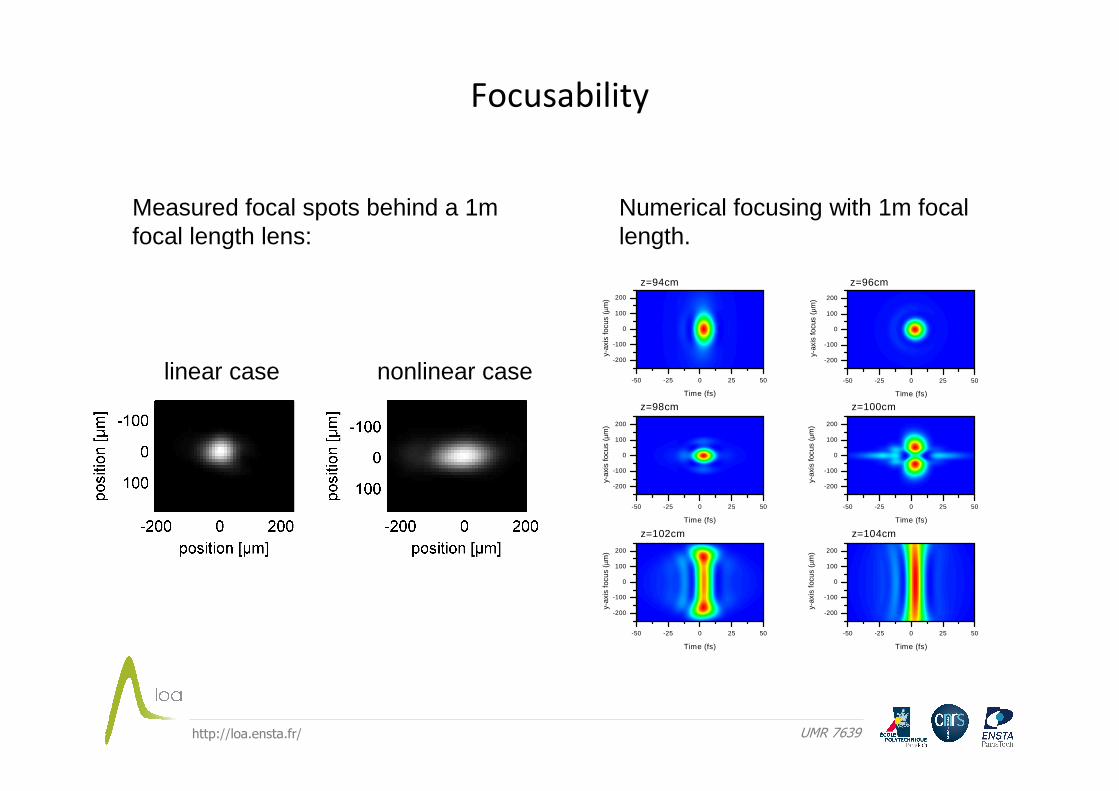
Focusability
linear case nonlinear case
Measured focal spots behind a 1m focal length lens:
-50 -25 0 25 50
-200
-100
0
100
200
Time (fs)
y-ax
is fo
cus
(µm
)
z=94cm
-50 -25 0 25 50
-200
-100
0
100
200
z=96cm
Time (fs)
y-ax
is fo
cus
(µm
)
-50 -25 0 25 50
-200
-100
0
100
200
z=98cm
Time (fs)
y-ax
is fo
cus
(µm
)
-50 -25 0 25 50
-200
-100
0
100
200
z=100cm
Time (fs)
y-ax
is fo
cus
(µm
)
-50 -25 0 25 50
-200
-100
0
100
200
z=102cm
Time (fs)
y-ax
is fo
cus
(µm
)
-50 -25 0 25 50
-200
-100
0
100
200
z=104cm
Time (fs)
y-ax
is fo
cus
(µm
)
Numerical focusing with 1m focal length.
http://loa.ensta.fr/ UMR 7639
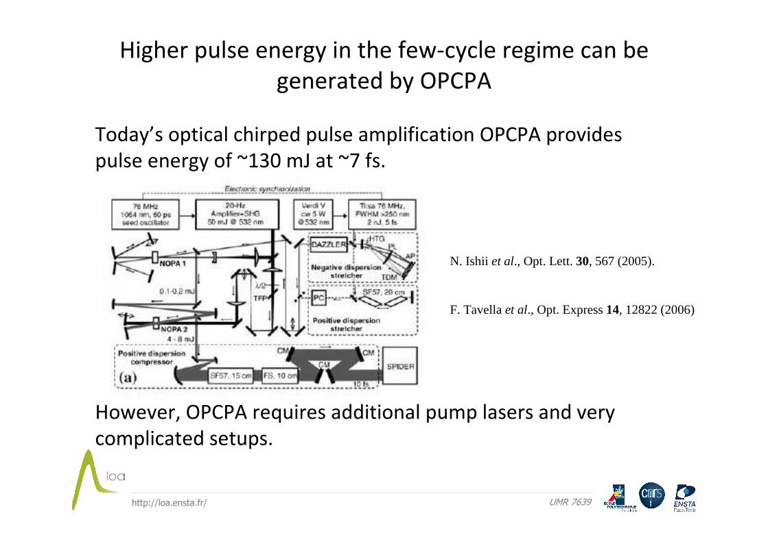
Higher pulse energy in the few-cycle regime can be
generated by OPCPA
Today’s optical chirped pulse amplification OPCPA provides
pulse energy of ~130 mJ at ~7 fs.
However, OPCPA requires additional pump lasers and very
complicated setups.
F. Tavella et al., Opt. Express 14, 12822 (2006)
N. Ishii et al., Opt. Lett. 30, 567 (2005).

http://loa.ensta.fr/ UMR 7639
( ) ( ) ( ) ( )( ){ }
( ) ( ) ( ) ( )( ) ( ) ( )
( )22
0
0020
2
2
1
,,,1
,,
..exp,,,,,
,,,,,~112,,~
−
−=
=
+−=
+
−−−−=∂
∫
∑
∑
−
ka
u
a
ni
ka
uk
dxxUtzyxa
tzy
cctizixUtzytzyx
tzyxNFzkvx
kiLzk
pnpp
p
a
a
p
ppp
pyp
gp
TpDfyz
ωβ
εκ
ωβκε
εωκωωββ
βωε
Numerical model based on the nonlinear envelope
equation (NEE)
Linear Part: mode selective dispersion and absorption,Space-time focusing
Nonlinear part: shock formation, plasma-defocusing, nonlinear ionization
Transformations betweenNormal space and mode space
Wave number, dispersion and absorption of TE waveguide modes

http://loa.ensta.fr/ UMR 7639
Numerical modeling
Quasi-guidedpropagation
Free propagation
y
x
z
Cosine modes
-1.0 -0.5 0.0 0.5 1.0
-1.0
-0.5
0.0
0.5
1.0
U3(x)
U5(x)
U(x)
x/a
U1(x)
0.0 0.1 0.2 0.3 0.4 0.50.0
0.2
0.4
0.6
0.8
1.0
Nor
mal
ized
pow
er
Propagation distance (m)
Attenuation2
1 )(zκ
2
3 )(zκ
2
5 )(zκ

http://loa.ensta.fr/ UMR 7639
700 750 800 850 900-10
-5
0
5
10
Wave length (nm)
-40 -20 0 20 40-10
-5
0
5
10
Fre
e w
aveg
uide
axi
s (m
m)
Time (fs)
10 20 30 40 50-10
-5
0
5
10
Duration (fs)
(a) (b) (c)