Embed Size (px)
Citation preview
RESEARCH Revista Mexicana de Fısica61 (2015) 330–337 SEPTEMBER-OCTOBER 2015
Phase map by fringe projection with dammann gratings: an application tomeasure small objects
A. Nava-Vegaa, J. Salinas-Lunab, E. Lunac, and J. Manuel NunezcaUniversidad Autonoma de Baja California, Tijuana, B.C. Mexico,
e-mail: [email protected] del Mar, campus PuertoAngel, Oaxaca, 70982, Mexico,
e-mail: [email protected] Nacional Autonoma de Mexico, Instituto de Astronomıa,
Observatorio Astronomico Nacional, Km. 107 Carretera Tijuana-Ensenada, Ensenada, Mexico, c.p. 22860, Mexico,e-mail: [email protected], [email protected]
Received 28 January 2015; accepted 28 May 2015
The phase of a suitable object was obtained with a fringe projection experiment by using phase shifting with Dammann gratings. As thespacing of the Dammann gratings can be manipulated, it is possible to generate projected thin fringes to improve details of the borders of theobject. These gratings have the property that their spacing is not constant, can be programmed, encoded and displayed with versatile perfor-mance using a monochromatic source light on a liquid crystal display LCD or by means of a DLP (Digital Light Projector) to develop fringeprojection experiments easily and at low cost. As result we have found a high-contrast projection fringes, side and rotation displacementscan be better adapted to measure an object. Some fringes images can be generated by fifth order Dammann gratings projected on objects≤ 20 cm of height.
Keywords: Diffraction; interference multiple; profiling; phase; spatial light modulator.
Empleando la tecnica de proyeccion de franjas se obtiene la fase de objetos, con corrimiento de fase empleando una rejilla binaria Dammann.Debido a que se puede manipular la resolucion espacial de las rejillas, podemos modificar el espesor de las franjas que se proyectan y mejorarlos detalles de los bordes del objeto. Las rejillas Dammann no tienen un espaciamiento constante, se puede programar y codificar de formaversatil usando luz monocromatica a traves de una pantalla de cristal lıquido LCD, o por medio de un proyector digital de luz DLP para laproyeccion de franjas, el DLP es una opcion de bajo costo y facil de realizarse. Como resultado, hemos encontrado franjas de alto contraste,los patrones de franjas codificados se pueden girar y desplazar adaptandolas a objetos≤ 20 cm de altura, En este trabajo se identifica que lasrejillas Dammann de orden 5 producen mejores resultados, que se observan en los contrastes de las imagenes obtenidas.
Descriptores: Difraccion; interferencia multiple; perfil; fase; modulador espacial.
PACS: 42.25.Fx; 42.79.Dj; 42.79.Hp; 42.30.-d.
1. Introduction
The purpose of this paper is demonstrate experimentally howto obtain the phase of a small object using a phase shiftingalgorithm (PS), and a light diffracting element with variablespacing, as is used in the classical Ronchi tests [1]. As advan-tage in this work, we control the spacing between bands gen-erating thin lines and improving the details of the phase, oftenused to improve the resolution of the measurement in geomet-ric scope, or with interferometry using monochromatic lightsources, a drawback with this option is that the experimentturns expensive. We used an LCD to display fine fringes withDammann gratings [2], in a fringes projection experimentsetup with monochromatic light source. Initially, the qualityof the patterns generated by the Dammann gratings was un-known for us; however, we were able to confirm the qualityof the projected Dammann fringes for the fringe projectionexperiment, using a binary grating named Dammann [3], wefound that a Dammann gratings in a programmable LCD ap-plied in profilometry technique has not been done. This workis based on the experience gained in Davis laboratory, wherewas possible to work with interference multiple patterns us-
ing a liquid crystal display (LCD), monochromatic light go-ing through a diffraction Dammann grating [2] producing aninterference pattern, of at least two orders of diffraction, gen-erating the width of a line sub-structured in its spatial period;this Dammann grating was mathematically characterized tobe displayed on the LCD. In our experiments we generateDammann gratings with different diffraction orders.
The fringe projection [4] is a non-contact technique, thatcan be performed either with incoherent or coherent light, il-luminating the object with a group of fringes generated bya sinusoidal or binary grating [5,6]. There are some disad-vantages with monochromatic light, since this type of illu-mination induces errors for speckles, produced when lightimpinges on dust particles on the gratings; in our devicewe reduced the speckles with optical filters. For incoherentlight, digital projectors (DLP) are employed for fringe projec-tion, producing undesired diffraction patterns called pixela-tion, and increasing when an LCD is used to display gratingsof variable frequency [7]. The pixelation produces an effecton high and low frequency images noise, reduced with a com-posed filter software, that consists of a mixture of frequen-tial and spatial filters, applied to the image where it was at-
PHASE MAP BY FRINGE PROJECTION WITH DAMMANN GRATINGS: AN APPLICATION TO MEASURE SMALL OBJECTS 331
tenuated the high-and-medium- frequency noise produced byLCD pixels, without affects the original shape of the fringes,and maintaining the original image intensity [8]. The incor-poration of LCD’s in optical tests, allows pre-programmingof gratings before are deployed [9]. The essential purposeof this work is, to demonstrate experimentally the interfer-ence multiple applied to profilometry in a process of se-lection of diffraction points, generated by Dammann grat-ings. The advantages of these systems allow lateral displace-ments, rotations at different angles, and even period vari-ations in real time to observe phase changes in diffractionorders. A secondary objective, is to show the experimentalmethodology and mathematical theory used to generate andcharacterize Dammann gratings. In order to test the perfor-mance of Dammann gratings in fringe projection with inco-herent illumination, we used a digital light projector (DLP)to project and measure an arbitrary object. The experimentson fringe projection with coherent illumination were consid-ered to demonstrate the patterns quality in certains points onthe image, such as acceptable definition of the image bor-der, homogeneous intensity and particularly free of bordereffects. This paper is organized as follows: a Dammann grat-ings description, design, and programming are presented onSec. 2. The experimental set-up to generate Dammann grat-ings is described on Sec. 3. The results and characteristicsof dynamic Dammann gratings are presented in Sec. 4. Sec-tion 5 presents an application of profilometry with Dammanngratings. Finally, Sec. 6 includes the discussion and conclu-sions of this study.
2. Dammann gratings
H. Dammann [2] was the first suggested the use of structuredbinary gratings (or sub-structured Katyl-type gratings [10]).Later, Zhou and Liu [11] improved the grating by generat-ing up to 32 orders of diffraction. The Diffraction Dammanngratings consist of FT- holograms designed to generate anarrangement of point sources with binary phases, values of0 and π have the same intensity on a remote field. Ourwork is supported by the physical phenomenon of multiple-interference, according to the well-known Huygens princi-ple [12]. The multiple interference pattern generation is con-sidered to be the N sources points, in our case a number ofsource points are generated for different orders of the gratingsdiffraction and are subsequently superimposed; it is quitewell-known that an increase of the spatial coherence gener-ates patterns with acceptable contrast. However, unlike linealsources, Dammann binary gratings have uniform diffractedlight intensity.
Fringe projection [4] is a technique where an object is il-luminated by a group of fringes with structured illuminationwhich can be performed with coherent or incoherent light.Projected point sources produced by this structured illumina-tion are highly energetic and efficient due to their diffractiveproperties.
2.1. Generation and calibration of Dammann gratings
In order to generate a Dammann grating, let us first consider atransmission functiont(x), of periodd, defined by two parts:the first part is valid betweenx = 0 and x = ω with atransmission value oft1, whose value remains constant onthe given range with a phase value ofϕ = 0. For a secondpart, betweenx = ω andx = d, the function has a constanttransmission value oft2, and a phase value ofϕ = π, Thetransmission function is represented by the relation:
t(x) =∞∑
n=−∞Cneinx, (1)
where the coefficientCn is given by,
Cn =1d
d∫
0
t(x)e−inxγdx, (2)
n is an integer number, and the parameterγ is
γ =2π
d. (3)
After taking the Fourier transform oft(x) we obtain:
T (p) =+∞∑
n−∞Cn(p− n), (4)
Wherep represents the bright point location, given by,
p =2π
λsin θ =
2π
dn. (5)
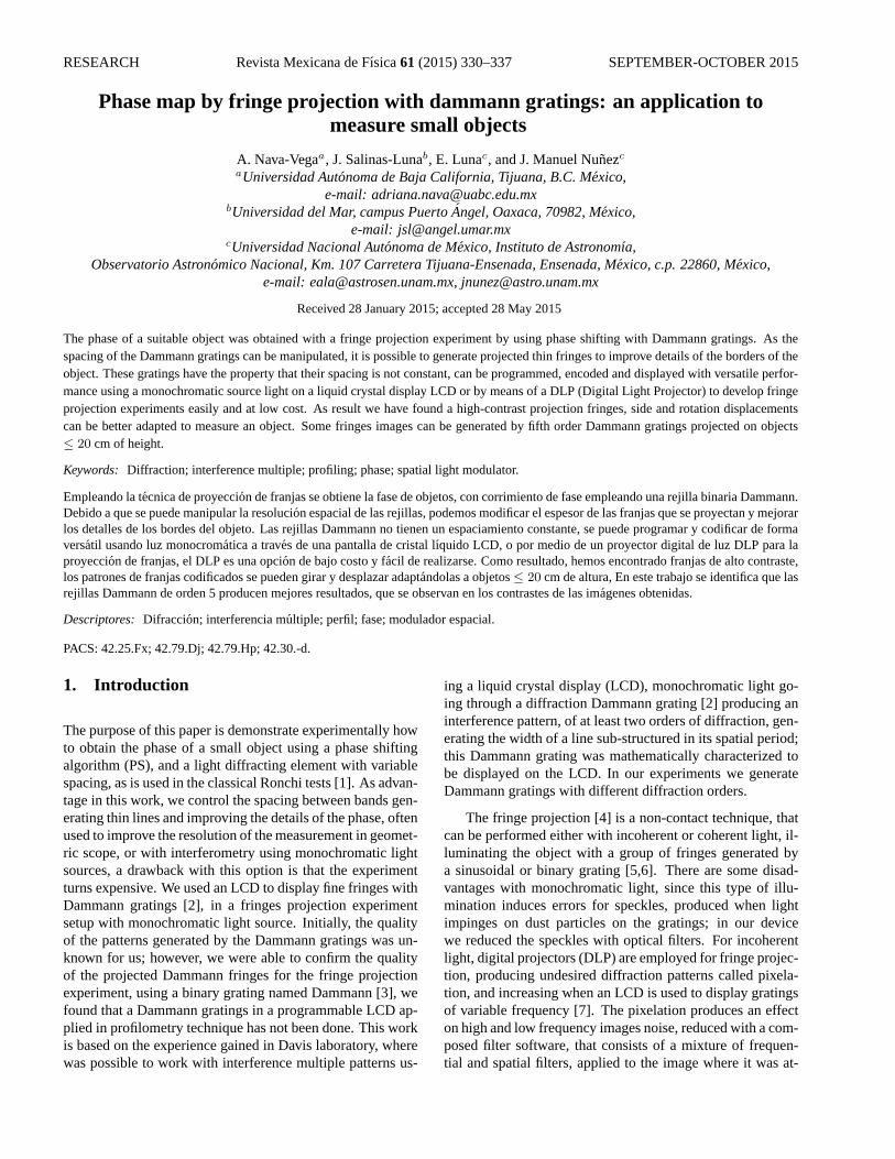
Dammann gratings are classified in function of the gen-erated diffraction points, which defines the structure of theDammann grating. Up to 32 orders of diffraction could begenerated according literature [11]. It is observed that thediffraction orders affects projected fringes, producing bettersharpness when the order of the fringes increases, assertionverified in Sec. 4. In order to select the order of the gratingto be used in this study, intensities of 3, 4, 5, 6, and 7th order
FIGURE 1. Binary gratings schematic diagram with five transitionspointsa, b, c, d, ande values, in the periodp. Intensity is uniformand equal to one. Phase’s values are 0 orπ.
Rev. Mex. Fıs. 61 (2015) 330–337
332 A. NAVA-VEGA, J. SALINAS-LUNA, E. LUNA, J. MANUEL NUNEZ
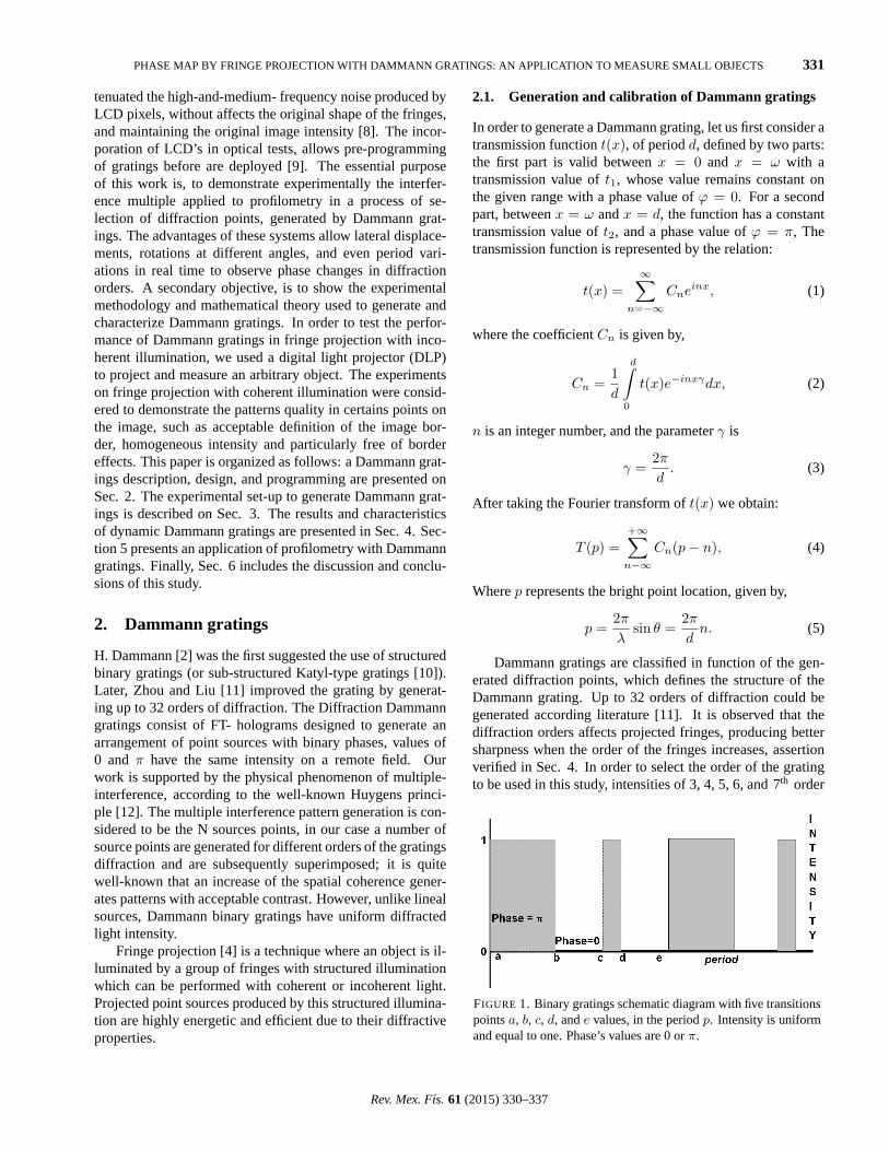
FIGURE 2. Experimental set-up to generate interference multiple patterns with Dammann diffraction gratings. Main component parts: Argonlaser, spatial filter, linear polarizer (LP), collimating lens (CL), diaphragm (D),λ/4 retarding plate (QWP), liquid-crystal display (LCD), asecond set of QWP, LP and diaphragm (D); and a CCD camera.
FT-Dammann gratings, were experimentally analyzed. A 5th
order grating resulted being the most suitable for our pur-poses because a grating of this type has an adequate perfor-mance derived from change rate defined byδ = Period grat-ing / Number of pixels, which is identified of the LCD quality(pixel density), a second reason is that a 5th order gratingcontains more defined lines than 3, 4, 6, and 7th order grat-ings on the region of transmission on the LCD. A schematicdiagram of the structure of this type of gratings is shown inFig. 1, where a 5th order grating with five generated pointsof diffraction are depicted, a Dammann grating in the period(p) provides a structure defined by transitions points. To gen-erate a 5th Dammann order structure, we set numbers, calledtransition points that defines the binary structure of one pe-riod, which have values ofa = 0, b = 0.03863, c = 0.39084,d = 0.65552, ande = 1, defining a value ofp = 1, con-sidered as the grating period; unlike binary gratings with aperiod (p), with two values of same width (w = p/2).
Figure 1 shows a Dammann grating, generated by transi-tion pointsa, b, c, d ande, a fingerprint diffraction patternwith the same values for intensity and phase for its diffrac-tion orders is produced. Thus, in order to design a Dammanngrating into an LCD, it is necessary to measure the LCD pixelarrangement and generate the pixel number for each segmentof the Dammann grating. From Eq. (2), the values of the co-efficients for the transmission function for this particular caseare:
Cn =1p
[ 0.03863∫
0
t(x)e−inxγdx +
0.39084∫
0.03863
t(x)e−inγdx
+
0.65552∫
0.39084
t(x)e−inγdx +
1∫
0.39084
t(x)e−inλdx
](6)
After solved, and some simplifications,
Cn = − 1inπ
{[cos(2nπb)− cos(2nπc) + cos(2nπd)− 1]
+ i[− sin(2nπb) + sin(2nπc)− sin(2nπd)]}
. (7)
With n = 2, -1, 0, 1, 2, the coefficientsCn can be repre-sented by,Cn = (−1/inπ)[A + iB], whereA andB are thereal and imaginary coefficients, respectively. The intensity ofthe 5th order Dammann gratings is therefore given by:
I = CnC∗n =1
π2n2[A2 + B2]. (8)
Equation (9) generates the estimation of the intensityvalue for each diffraction order, which for this case is equalto 0.7863. Dammann gratings used in this study were pro-grammed with multiple values ofδ identifying on this pro-cess the best value for the 5th diffraction order grating.
3. Experimental set-up for generating fringeprojection with Dammann gratings
Figure 2 shows an optical system set up prepared for gen-erating multiple interference, a coherent laser light from anArgon source (λ = 458 nm, (for Figs. 4 to 11) expandedand filtered by an objective microscope lens located at a fo-cal distance from a collimator lens (CL) and a diaphragm (D).The device has also a linear polarizer and a density filter tocontrol the incidental light intensity on the LCD (HOLOEYELC2002). LCD dimensions can be scaled from800×600 pix-els up to1024×800 pixels. As the main function of the LCDis to modulate the phase of the diffracted light, it is importantto achieve its optimal performance [13]. To do it, a linear po-larizer (LP) and a retarding quarter plate (QWP) are carefullyoriented to the left and right side of the LCD. The gratings tobe used are programmed and codified to be displayed on theLCD, which is aligned and located in a perpendicular posi-tion to the optical axis to avoid inclination errors (tilt = 0).
Rev. Mex. Fıs. 61 (2015) 330–337
PHASE MAP BY FRINGE PROJECTION WITH DAMMANN GRATINGS: AN APPLICATION TO MEASURE SMALL OBJECTS 333
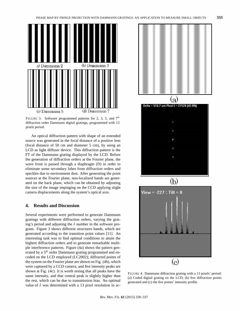
FIGURE 3. Software programmed patterns for 2, 3, 5, and 7th
diffraction order Dammann digital gratings, programmed with 13pixels period.
An optical diffraction pattern with shape of an extendedsource was generated in the focal distance of a positive lens(focal distance of 50 cm and diameter 5 cm), by using anLCD as light diffuser device. This diffraction pattern is theFT of the Dammann grating displayed by the LCD. Beforethe generation of diffraction orders at the Fourier plane, thewave front is passed through a diaphragm (D) in order toeliminate some secondary lobes from diffraction orders andspeckles due to environment dust. After generating the pointsources at the Fourier plane, non-localized bands are gener-ated on the back plane, which can be obtained by adjustingthe size of the image impinging on the CCD applying slightcamera displacements along the system’s optical axis.
4. Results and Discussion
Several experiments were performed to generate Dammanngratings with different diffraction orders, varying the grat-ing’s period and adjusting theδ number in the software pro-gram. Figure 3 shows different structures bands, which aregenerated according to the transition point values [11]. Aninteresting task was to find optimal conditions to attain thehighest diffraction orders and to generate remarkable multi-ple interference patterns. Figure (4a) shows the pattern gen-erated by a 5th order Dammann grating programmed and en-coded on the LCD employed (LC2002); diffracted points ofthe system on the Fourier plane are shown on Fig. (4b), whichwere captured by a CCD camera, and five intensity peaks areshown at Fig. (4c). It is worth noting that all peaks have thesame intensity, and that central peak is slightly higher thanthe rest, which can be due to transmission bias. An optimalvalue ofδ was determined with a 13 pixel resolution in ac-
FIGURE 4. Dammann diffraction grating with a 13 pixels’ period:(a) Coded digital grating on the LCD; (b) five diffraction pointsgenerated and (c) the five points’ intensity profile.
Rev. Mex. Fıs. 61 (2015) 330–337
334 A. NAVA-VEGA, J. SALINAS-LUNA, E. LUNA, J. MANUEL NUNEZ
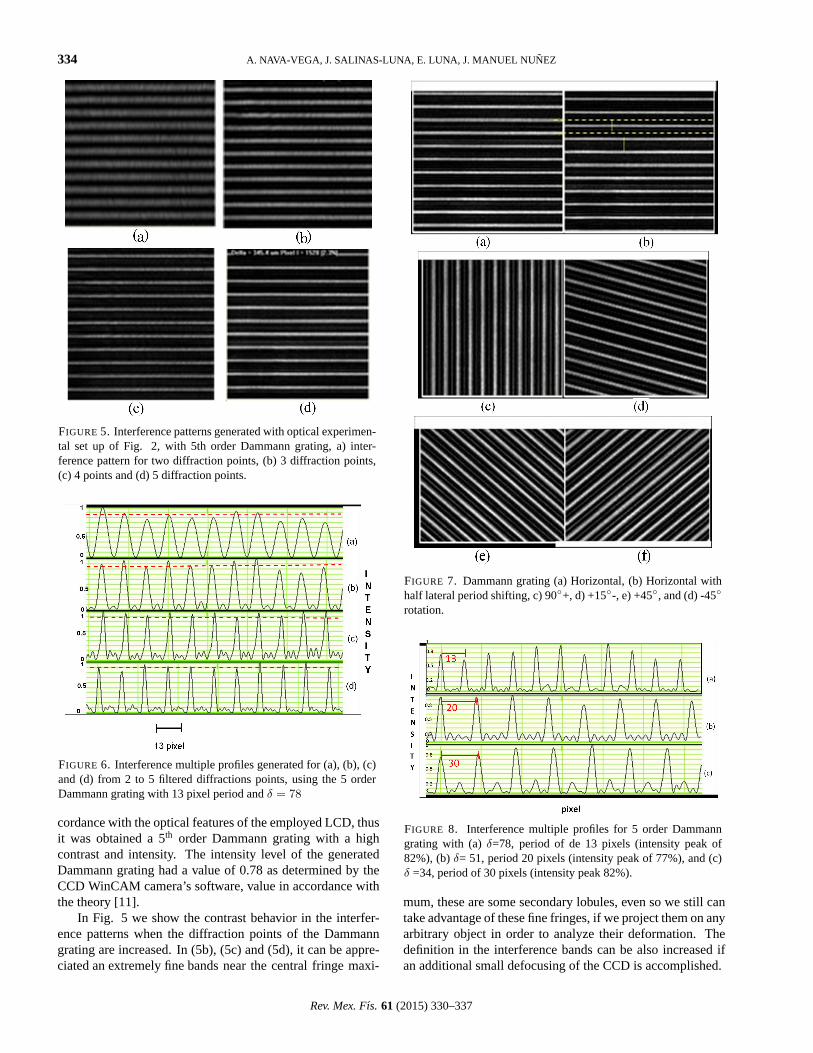
FIGURE 5. Interference patterns generated with optical experimen-tal set up of Fig. 2, with 5th order Dammann grating, a) inter-ference pattern for two diffraction points, (b) 3 diffraction points,(c) 4 points and (d) 5 diffraction points.
FIGURE 6. Interference multiple profiles generated for (a), (b), (c)and (d) from 2 to 5 filtered diffractions points, using the 5 orderDammann grating with 13 pixel period andδ = 78
cordance with the optical features of the employed LCD, thusit was obtained a 5th order Dammann grating with a highcontrast and intensity. The intensity level of the generatedDammann grating had a value of 0.78 as determined by theCCD WinCAM camera’s software, value in accordance withthe theory [11].
In Fig. 5 we show the contrast behavior in the interfer-ence patterns when the diffraction points of the Dammanngrating are increased. In (5b), (5c) and (5d), it can be appre-ciated an extremely fine bands near the central fringe maxi-
FIGURE 7. Dammann grating (a) Horizontal, (b) Horizontal withhalf lateral period shifting, c) 90◦+, d) +15◦-, e) +45◦, and (d) -45◦
rotation.
FIGURE 8. Interference multiple profiles for 5 order Dammanngrating with (a)δ=78, period of de 13 pixels (intensity peak of82%), (b)δ= 51, period 20 pixels (intensity peak of 77%), and (c)δ =34, period of 30 pixels (intensity peak 82%).
mum, these are some secondary lobules, even so we still cantake advantage of these fine fringes, if we project them on anyarbitrary object in order to analyze their deformation. Thedefinition in the interference bands can be also increased ifan additional small defocusing of the CCD is accomplished.
Rev. Mex. Fıs. 61 (2015) 330–337
PHASE MAP BY FRINGE PROJECTION WITH DAMMANN GRATINGS: AN APPLICATION TO MEASURE SMALL OBJECTS 335
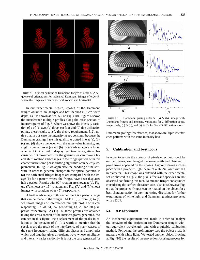
FIGURE 9. Optical patterns of Dammann fringes of order 5. A se-quence of orientations for incidental Dammann fringes of order 5,where the fringes are can be vertical, rotated and horizontal.
In our experimental set-up, images of the Dammannfringes obtained are sharper and best defined at 3 cm focusdepth, as it is shown at Sec. 5.2 on Fig. (10). Figure 6 showsthe interference multiple profiles along the cross section ofinterferograms of Fig. 5, where we shows the intensity varia-tion of a of (a) two, (b) three, (c) four and (d) five diffractionpoints, these results satisfy the theory requirements [12], no-tice that in our case the intensity keeps constant, because theDammann gratings have this quality. A dotted line at (a), (b),(c) and (d) shows the level with the same value intensity, andslightly deviations at (a) and (b). Some advantages are foundwhen an LCD is used to display the Dammann gratings, be-cause with 3 movements for the gratings we can make a lat-eral shift, rotation and changes in the fringes period, with thischaracteristic some phase shifting algorithms can be easy im-plemented. In Fig. 7 we appreciate the handling of the soft-ware in order to generate changes in the optical patterns, in(a) the horizontal fringes images are compared with the im-age (b) for a pattern where the fringes have been displacedhalf a period. Results with 90◦ rotation are shown at (c). Fig-ure (7d) shows a + 15◦ rotation, and Fig. (7e) and (7f) showsimages with rotations of± 45◦, respectively.
A further advantage in this experiment is a period changethat can be made in the fringes. At Fig. (8), from (a) to (c)we shows images of interference multiple profile with cor-respondingδ = 78, 51, 34, generating 13, 20 and 30 pixelperiod respectively. As Fig. 6, these profiles are obtainedtaking the cross section of the interferograms generated. Wecan see in this figure, the displacement of the peaks in re-lation to the behavior ofδ. It is worth to mention that thespeckles are the result of the interference of many waves, ofthe same frequency, having different phases and amplitudeswhich add together gives a resultant wave whose amplitude,and intensity varies randomly, it is not the case generated for
FIGURE 10. Dammann grating order 5. (a) & (b): image withDammann fringes and intensity variations for 2 diffraction spots,respectively, (c) & (d), and (e) & (f), for 3 and 5 diffraction spots.
Dammann gratings interference, that shows multiple interfer-ence patterns with the same intensity level.
5. Calibration and best focus
In order to assure the absence of pixels effect and speckleson the images, we changed the wavelength and observed ifpixel errors appeared on the images. Figure 9 shows a chesspiece with a projected light beam of a He-Ne laser with 0.1m diameter. This image was obtained with the experimentalset-up showed in Fig. 2; the pixel effects and speckles are notobserved confirming this fact. Dammann fringes are sprainedconsidering the surface characteristics; also it is shown at Fig.9 that the projected fringes can be rotated on the object for abest characterization in any interesting direction, for furtherexperiments of white light, and Dammann gratings projectedwith a DLP.
5.1. DLP Experiment
An incoherent experiment was made in order to analyzethe behavior of the projection for Dammann fringes with-out equivalent wavelength, and with a suitable calibrationmethod. Following the profilometry test, the object phase ismeasure with white light. We tested another object showingat Fig. (10) the results of the projection focusing process for
Rev. Mex. Fıs. 61 (2015) 330–337
336 A. NAVA-VEGA, J. SALINAS-LUNA, E. LUNA, J. MANUEL NUNEZ
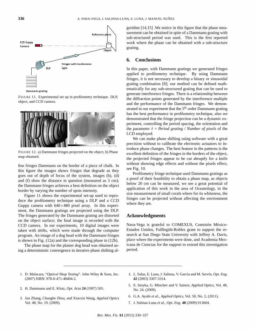
FIGURE 11. Experimental set up in profilometry technique. DLP,object, and CCD camera.
FIGURE 12. a) Dammann fringes projected on the object, b) Phasemap obtained.
fine fringes Dammann on the border of a piece of chalk. Inthis figure the images shows fringes that degrade as theygoes out of depth of focus of the system, images (b), (d)and (f) show the distance in question (measured as 3 cm);the Dammann fringes achieves a best definition on the objectborder by varying the number of spots intensity.
Figure 11 shows the experimental set-up used to repro-duce the profilometry technique using a DLP and a CCDGuppy camera with 640×480 pixel array. In this experi-ment, the Dammann gratings are projected using the DLP.The fringes generated by the Dammann grating are distortedon the object surface; the final image is recorded with theCCD camera. In our experiments, 10 digital images weretaken with shifts, which were made through the computerprogram. An image of a dog head with the Dammann fringesis shown in Fig. (12a) and the corresponding phase in (12b).
The phase map for the plaster dog head was obtained us-ing a deterministic convergence in iterative phase shifting al-
gorithm [14,15] .We notice in this figure that the phase mea-surement can be obtained in spite of a Dammann grating withsub-structured period was used. This is the first reportedwork where the phase can be obtained with a sub-structuregrating.
6. Conclusions
In this paper, with Dammann gratings we generated fringesapplied to profilometry technique. By using Dammannfringes, it is not necessary to develop a binary or sinusoidalgrating combination [8]; our method can be defined math-ematically for any sub-structured grating that can be used togenerate interference fringes. There is a relationship betweenthe diffraction points generated by the interference multipleand the performance of the Dammann fringes. We demon-strated in our experiment that the 5th order Dammann gratinghas the best performance in profilometry technique, also wedemonstrated that the fringe projection can be a dynamic ex-periment, controlling the period spacing, the orientation andthe parameterδ = Period grating / Number of pixelsof theLCD employed.
We can make phase shifting using software with a greatprecision without to calibrate the electronic actuators to in-troduce phase changes. The best feature in the patterns is theexcellent definition of the fringes in the borders of the object,the projected fringes appear to be cut abruptly for a knifewithout showing edge effects and without the pixels effect,see Fig. 10.
Profilometry fringe technique used Dammann gratings asa proof of their feasibility to obtain a phase map, as objectsbelow 20 cm can be measured, we see a great potential ofapplication of this work in the area of Oceanology, in thesize measurement of small corals where for its whiteness, thefringes can be projected without affecting the environmentwhere they are.
Acknowledgments
Nava-Vega is grateful to COMEXUS, Comision Mexico-Estados Unidos, Fullbrgith-Robles grant to support the re-search at San Diego State University with Jeffrey A. Davis,place where the experiments were done, and Academia Mex-icana de Ciencias for the support to extend this investigationperiod.
1. D. Malacara, “Optical Shop Testing”. John Wiley & Sons, Inc.(2007) ISBN: 978-0-471-48404-2.
2. H. Dammann and E. Klotz,Opt. Acta24 (1997) 505.
3. Jun Zhang, Changhe Zhou, and Xiaoxin Wang,Applied OpticsVol. 48, No. 19. (2009).
4. L. Salas, E. Luna, J. Salinas, V. Garcıa and M. Servın,Opt. Eng.42 (2003) 3307-3314.
5. E. Stoyka, G. Minchev and V. Sainov,Applied Optics, Vol. 48,No. 24. (2009).
6. G.A. Ayubi et al., Applied Optics, Vol. 50, No. 2, (2011).
7. J. Salinas-Lunaet al., Opt. Eng. 48 (2009) 013604.
Rev. Mex. Fıs. 61 (2015) 330–337

PHASE MAP BY FRINGE PROJECTION WITH DAMMANN GRATINGS: AN APPLICATION TO MEASURE SMALL OBJECTS 337
8. M. Mora-Gonzalezet al,. Proceeding of SPIE, 8436(2012) 1-6.
9. C. Quan, J.C. Tay, X.Kang, X.Y. He, and H.M. Shang,Appl.Opt.42 (2005) 2329-2335.
10. R.H. Katyl,Appl. Opt.11 (1972) 2278-2285.
11. Ch. Zhou, and L. Liu,Applied optics, vol. 34, No. 26 (1995).
12. E. Hecht, “Optics”, Pearson Addison Wesley (2002).
13. J.A. Davis, J. Nicolas, and A. Marquez, “Phasor analysis of
eigenvectors generated in liquid-crystal displays”. 1 August2002/ Vol. 41, No. 22/Applied Optics, / Vol. 41, No. 22/ 1August 2002.
14. E. Luna, L. Salas, E. Sohn, E. Ruiz, J.M. Nunez, and J. Herrera,Appl. Opt.48 (2009) 1494-1501.
15. J. Herrera, E. Luna, L. Salas, E. Sohn, and E. Ruiz,Appl. Opt.52 (2013) 1913-1918.
Rev. Mex. Fıs. 61 (2015) 330–337