Embed Size (px)
Citation preview

F
GB
I
E
D
P
PHTJ 14 / 19
Pompe à chaleur haute température avec équipement hydraulique (chauffage seulement) - Fluide réfrigérant R 407 C
High temperature heat pump with hydraulic equipment (heating only) - R 407 C refrigerant
Refrigeratore d’acqua in versione pompa di calore alta temperatura con sezione idronicaincorporata (unicamente riscaldamento) - Fluido refrigerante R 407 C
Bomba de calor de alta temperatura con equipamiento hidráulico (sólo calefacción) - Fluido refrigerante R 407 C
Hochtemperatur-Wärmepumpe mit Hydraulikmodul (Nur Heizen) - Kältemittel R 407 C
Bomba de calor alta temperatura com equipamento hidráulico (somente aquecimento) - Fluído refrigerante R 407 C
Janvier 2009 10 11 520 - F.GB.I.E.D.P - 03
NOTICE D’INSTALLATION
INSTALLATION INSTRUCTION
MANUALE D’INSTALLAZIONE
MANUALDE INSTALACIÓN
AUFSTELLUNGS-HANDBUCH
INSTRUÇÕESDE INSTALAÇÃO
(Etiquette signalétique)
GB
2
SUMMARY
1 - GENERALITIES
1.1 - GENERAL SUPPLY CONDITIONS• Generally speaking, the material is transported at the consignee’s risk.• The consignee must immediately provide the carrier with written reserves if he finds any damage caused during transport.
1.2 - RECOMMENDATIONS• Prior to all servicing or other actions on the equipment, installation, commissioning, operation, or maintenance, the
personnel in charge of these operations shall become familiar with the instructions and recommendations provided in theinstallation manual of the unit as well as the elements of the project's technical file.
• The personnel responsible for receiving the unit must conduct a visual inspection in order to identify all damage to whichthe unit may have been subjected during transport: refrigerating circuit, electrical cabinet, cassis and cabinet.
• The unit must be installed, started, maintained, serviced by qualified and authorised personnel, in compliance with therequirements of all directives, laws and regulations and in accordance with standard trade practices.
• During installation, troubleshooting and maintenance operations, the use of pipes as a step: under the stress, the pipe mayrupture and the refrigerant may cause serious burns.
MARKING
This product marked conforms to the essential requirements of the Directives:- Low voltage no. 2006/95/EC.- Electromagnetic Compatibility no. 89/336 EEC, modified 92/31 and 93/68 EEC.
1 - Generalities . . . . . . . . . . . . . . . . . . . . . . . . . . . . . . . . . . . . . . . . . . 22 - Presentation . . . . . . . . . . . . . . . . . . . . . . . . . . . . . . . . . . . . . . . . . 33 - Installation . . . . . . . . . . . . . . . . . . . . . . . . . . . . . . . . . . . . . . . . . . . 44 - Connections . . . . . . . . . . . . . . . . . . . . . . . . . . . . . . . . . . . . . . . . . 45 - Operation of "ECH" electronic control . . . . . . . . . . . . . . . . . . . . . . 66 - Accessories . . . . . . . . . . . . . . . . . . . . . . . . . . . . . . . . . . . . . . . . . 127 - Starting . . . . . . . . . . . . . . . . . . . . . . . . . . . . . . . . . . . . . . . . . . . . 138 - Maintenance instruction . . . . . . . . . . . . . . . . . . . . . . . . . . . . . . . 149 - Troubleshooting . . . . . . . . . . . . . . . . . . . . . . . . . . . . . . . . . . . . . 14
10 - Circulator curves . . . . . . . . . . . . . . . . . . . . . . . . . . . . . . . . . . . . . 1511 - Pressure tables . . . . . . . . . . . . . . . . . . . . . . . . . . . . . . . . . . . . . . 1612 - Wiring diagrams . . . . . . . . . . . . . . . . . . . . . . . . . . . . . . . . . . . . . 18
R 407 C• Fluid R 407 C is not a pure fluid but a blend composed of:
- 23% R 32 + 25% R 125 + 52% R 134 A.• The compressors approved for operation with this fluid are
filled beforehand with polyalcohol oil. Contrary to mineral oil, it is very hygroscopic: it absorbs thehumidity of the ambient air very quickly. This can modify itslubricant properties and lead in time to the destruction of thecompressor.
MAINTENANCE INSTRUCTIONS
1 - Never add oil to the appliance; the compressor is filledwith polyalcohol oil, a special oil which cannot tolerate thepresence of other oils.
2 - The instruments used for:- filling,- pressure measurements,- emptying under vacuum,- recovering the fluid,
must be compatible and only used for the R 407 C fluid.
3 - The weight of the refrigerant contained in the storagebottle must be checked constantly. Do not use it from themoment the remaining weight is less than 10% of the totalweight.
4 - In the case of a new charge:- do not use the charging cylinder,- use a balance and a dip pipe type R 407 C cylinder,- charge the weight of R 407 C as per the value indicated
on the unit’s identification plate,- IMPORTANT: see instruction 3 above.
5 - The charge must be undertaken in liquid phase.
6 - In case of leakage, do not complete the charge: recoverthe remaining refrigerant for recycling and perform a totalcharge.Recovery, recycling or the destruction of the fluid must bedone in compliance with the laws in force in the countryconcerned.
7 - If the refrigerant circuit is opened, you must:- avoid the entry of air into the circuit as much as
possible,- replace the filter drier,- perform the "vacuum operation" at a minimum level of
0.3 mbar (static).
8 - Do not release R 407 C fluid into the atmosphere. Thisfluid is a fluorinated greenhouse gases, covered by theKyoto Protocol with a Global Warming Potential (GWP) = 1653 - (EC Directive 842 / 2006).
APPLIANCES FILLED WITH R 407 C
GB
3
1
15 5 6 8 7
10
3
14
11
12
13
9
2
4
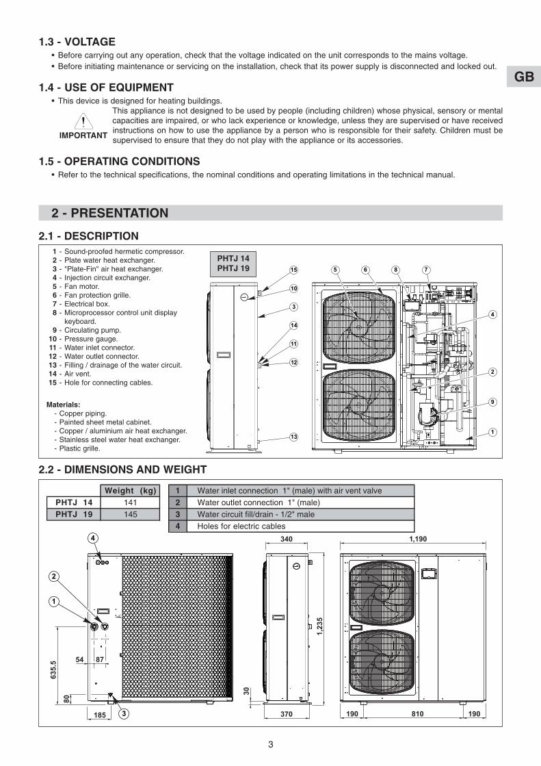
1 - Sound-proofed hermetic compressor.2 - Plate water heat exchanger.3 - "Plate-Fin" air heat exchanger.4 - Injection circuit exchanger.5 - Fan motor.6 - Fan protection grille.7 - Electrical box.8 - Microprocessor control unit display
keyboard.9 - Circulating pump.
10 - Pressure gauge.11 - Water inlet connector.12 - Water outlet connector.13 - Filling / drainage of the water circuit.14 - Air vent.15 - Hole for connecting cables.
Materials:- Copper piping.- Painted sheet metal cabinet.- Copper / aluminium air heat exchanger.- Stainless steel water heat exchanger.- Plastic grille.
2 - PRESENTATION
2.1 - DESCRIPTION
1.3 - VOLTAGE• Before carrying out any operation, check that the voltage indicated on the unit corresponds to the mains voltage.• Before initiating maintenance or servicing on the installation, check that its power supply is disconnected and locked out.
1.4 - USE OF EQUIPMENT• This device is designed for heating buildings.
This appliance is not designed to be used by people (including children) whose physical, sensory or mentalcapacities are impaired, or who lack experience or knowledge, unless they are supervised or have receivedinstructions on how to use the appliance by a person who is responsible for their safety. Children must besupervised to ensure that they do not play with the appliance or its accessories.
1.5 - OPERATING CONDITIONS• Refer to the technical specifications, the nominal conditions and operating limitations in the technical manual.
PHTJ 14PHTJ 19
2.2 - DIMENSIONS AND WEIGHT
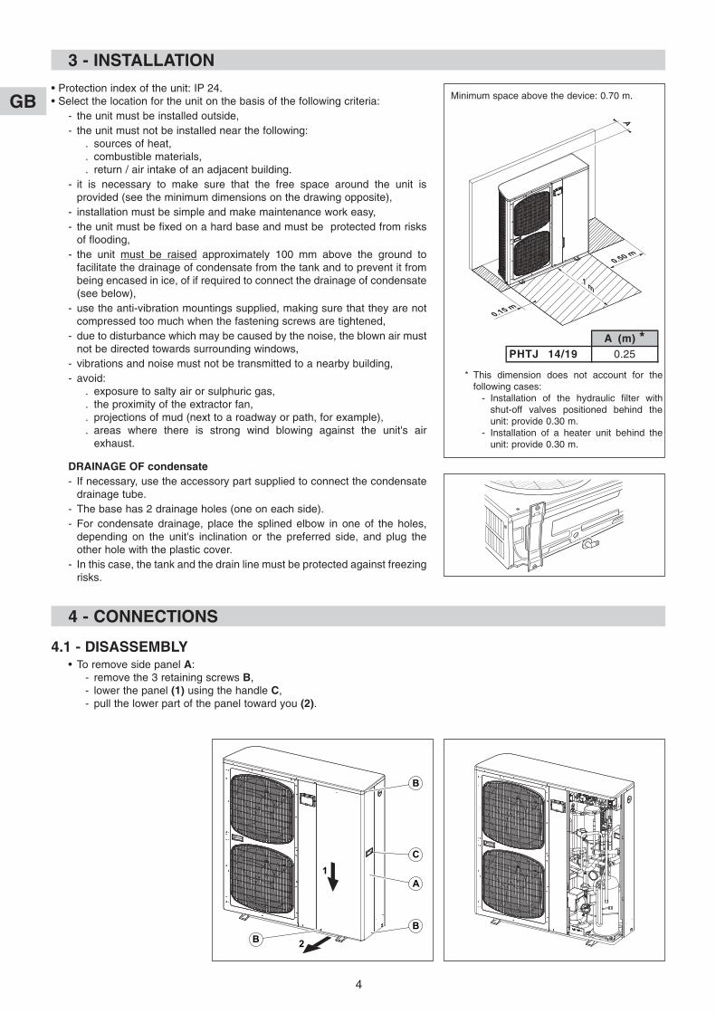
Weight (kg)PHTJ 14 141
PHTJ 19 145
1 Water inlet connection 1" (male) with air vent valve
2 Water outlet connection 1" (male)
3 Water circuit fill/drain - 1/2" male
4 Holes for electric cables
340
30
1,23
5
190 190810370
1,190
185
8754
80
635.
5
4
3
1
2
IMPORTANT
GB
4
3 - INSTALLATION
• Protection index of the unit: IP 24.• Select the location for the unit on the basis of the following criteria:
- the unit must be installed outside,- the unit must not be installed near the following:
. sources of heat,
. combustible materials,
. return / air intake of an adjacent building.- it is necessary to make sure that the free space around the unit is
provided (see the minimum dimensions on the drawing opposite),- installation must be simple and make maintenance work easy,- the unit must be fixed on a hard base and must be protected from risks
of flooding,- the unit must be raised approximately 100 mm above the ground to
facilitate the drainage of condensate from the tank and to prevent it frombeing encased in ice, of if required to connect the drainage of condensate(see below),
- use the anti-vibration mountings supplied, making sure that they are notcompressed too much when the fastening screws are tightened,
- due to disturbance which may be caused by the noise, the blown air mustnot be directed towards surrounding windows,
- vibrations and noise must not be transmitted to a nearby building,- avoid:
. exposure to salty air or sulphuric gas,
. the proximity of the extractor fan,
. projections of mud (next to a roadway or path, for example),
. areas where there is strong wind blowing against the unit's airexhaust.
DRAINAGE OF condensate- If necessary, use the accessory part supplied to connect the condensate
drainage tube.- The base has 2 drainage holes (one on each side).- For condensate drainage, place the splined elbow in one of the holes,
depending on the unit's inclination or the preferred side, and plug theother hole with the plastic cover.
- In this case, the tank and the drain line must be protected against freezingrisks.
4 - CONNECTIONS
4.1 - DISASSEMBLY• To remove side panel A:
- remove the 3 retaining screws B,- lower the panel (1) using the handle C,- pull the lower part of the panel toward you (2).
B
C
A
B
2
1
B
A (m) *PHTJ 14/19 0.25
* This dimension does not account for thefollowing cases:
- Installation of the hydraulic filter withshut-off valves positioned behind theunit: provide 0.30 m.
- Installation of a heater unit behind theunit: provide 0.30 m.
Minimum space above the device: 0.70 m.
GB
5
4.2 - HYDRAULIC CONNECTION• Connect the water pipes to the corresponding connections. See Ø and position on page 3.• Install the hydraulic filter (supplied) on the water intake. Connect it using 2 isolation valves (not supplied) for cleaning
purposes.• Install a shut-off valve (not supplied) if a fill / drainage connection is used.• CAUTION:
This device is not fitted with an expansion tank or a safety valve.These elements must be incorporated into the installation’s hydraulic circuit.For installation of an electric heating module, install this safety valve in direct connection with the module (without isolationvalve).NOTE: "Water connection hose" accessories may be used (refer to the accessories paragraph).
4.3 - ELECTRICAL CONNECTION4.3.1 - GENERAL:
• The acceptable voltage variation is: ± 10% during operation.• The electrical connection conduits must be fixed.• Use the cable clamps at the rear of the unit and route the wires under the electric panel, at the level of the terminal strips.• Class 1 unit.• The electrical installation must comply with the standards and regulations applicable where the unit is being installed (in
particular NF C 15-100 ≈ IEC 364).
4.3.2 - POWER SUPPLY• The power supply must come from an isolation and electric protection device (not supplied) in accordance with existing
regulations.• Protection must be guaranteed by a double-pole circuit breaker for single-phase devices and a three-pole circuit
breaker for three-phase devices (not supplied). See ratings in the table below.Note: The unit is designed to be connected to a power supply having a TT neutral regime (neutral to ground) or TN.S regime(to neutral) as per NF C 15-100.
POWER SUPPLY CABLE• Cross-section: see table below.• The sections are given as an indication only. They have to be verified and adapted, if necessary, according to the
installation conditions and the standards in force.• Make the electrical connections to the terminal board as per the electrical diagrams.
CURRENTS AND CROSS-SECTIONS
CAUTION: In the case of a three-phase power supply, prior to commissioning the unit, make sure that the phase rotationorder is correct. If the rotation order is not respected, the compressor will turn backwards (and make anabnormal noise). To fix this, simply invert the 2 phases.
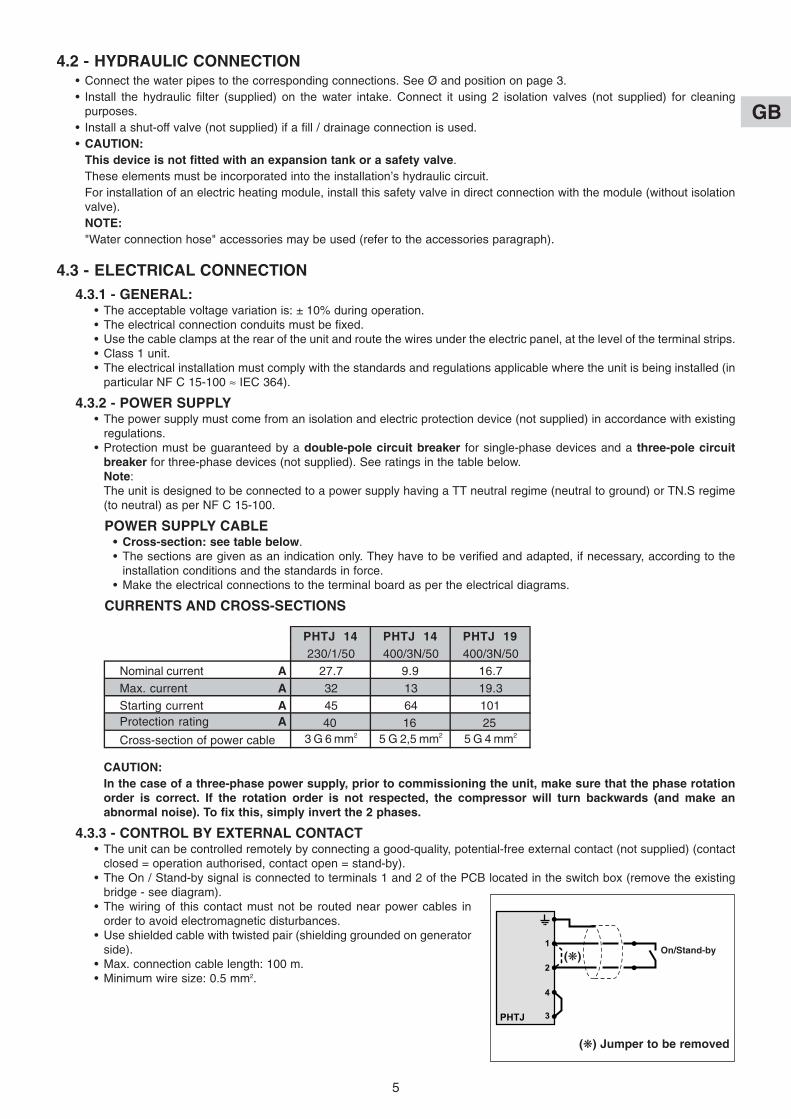
4.3.3 - CONTROL BY EXTERNAL CONTACT• The unit can be controlled remotely by connecting a good-quality, potential-free external contact (not supplied) (contact
closed = operation authorised, contact open = stand-by).• The On / Stand-by signal is connected to terminals 1 and 2 of the PCB located in the switch box (remove the existing
bridge - see diagram).• The wiring of this contact must not be routed near power cables in
order to avoid electromagnetic disturbances.• Use shielded cable with twisted pair (shielding grounded on generator
side).• Max. connection cable length: 100 m.• Minimum wire size: 0.5 mm2.
PHTJ 14 PHTJ 14 PHTJ 19230/1/50 400/3N/50 400/3N/50
Nominal current A 27.7 9.9 16.7
Max. current A 32 13 19.3
Starting current A 45 64 101Protection rating A 40 16 25
3 G 6 mm2 5 G 2,5 mm2 5 G 4 mm2Cross-section of power cable
1
2
4
3PHTJ
On/Stand-by
(k) Jumper to be removed
(k)
GB
6
6 4 2
7
8 3 9 1
5
4.3.4 - REMOTE CONTROL• See paragraph "accessories".
4.3.5 - MISCELLANEOUS• Alarm transfer:
Potential-free changeover contact (2A - 250 VAC max.) available on the unit's terminal strip (terminals 5 (common), 6and 7 of the printed circuit) for remote signaling. See schematic.- In case of alarm:
- contact open between terminals 5 and 6,- contact closed between terminals 5 and 7.
5 - OPERATION OF “ECH” ELECTRONIC CONTROL
• See the wiring diagrams at the back of the manual.
5.1 - DELIVERY STATE• The control unit is supplied fitted in the machine and
factory pre-set.• All the connections are made except those concerning the
available signals or the options.
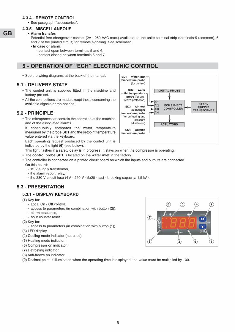
5.2 - PRINCIPLE• The microprocessor controls the operation of the machine
and of the associated alarms.It continuously compares the water temperaturemeasured by the probe SD1 and the setpoint temperaturevalue entered via the keyboard.Each operating request produced by the control unit isindicated by the light (6) (see below).This light flashes if a safety delay is in progress. It stays on when the compressor is operating.
• The control probe SD1 is located on the water inlet in the factory.• The controller is connected on a printed circuit board on which the inputs and outputs are connected.
On this board: - 12 V supply transformer,- the alarm report relay,- the 230 V circuit fuse (4 A - 250 V - 5x20 - fast - breaking capacity: 1.5 kA).
5.3 - PRESENTATION
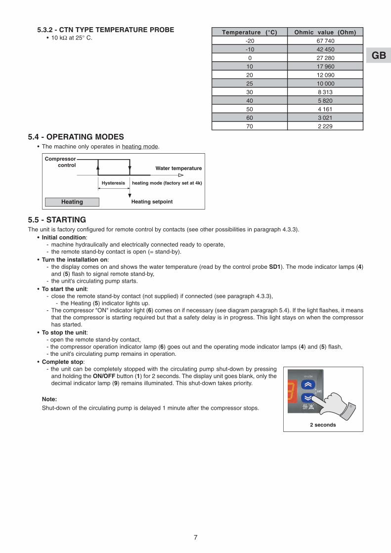
5.3.1 - DISPLAY KEYBOARD(1) Key for:
- Local On / Off control,- access to parameters (in combination with button (2)),- alarm clearance,- hour counter reset.
(2) Key for:- access to parameters (in combination with button (1)).
(3) LED display.(4) Cooling mode indicator (not used).(5) Heating mode indicator.(6) Compressor on indicator.(7) Defrosting indicator.(8) Anti-freeze on indicator.(9) Decimal point: if illuminated when the operating time is displayed, the value must be multiplied by 100.
DIGITAL INPUTS
12 VAC SUPPLY
TRANSFORMER
ACTUATORS
SD1 Water inlettemperature probe
(for control)
SD2 Wateroutlet temperature
probe (for anti-freeze protection)
SD3 Air heatexchanger
temperature probe(for defrosting and
pressureadjustment)
SD4 Outsidetemperature probe
ECH 210 BDTCONTROLLER
AI1AI2AI3AI4
GB
7
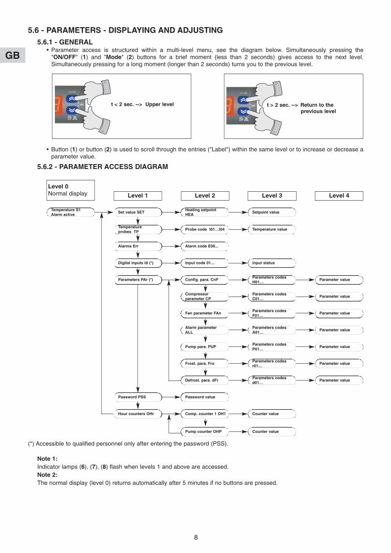
5.3.2 - CTN TYPE TEMPERATURE PROBE• 10 kΩ at 25° C.
5.4 - OPERATING MODES• The machine only operates in heating mode.
5.5 - STARTINGThe unit is factory configured for remote control by contacts (see other possibilities in paragraph 4.3.3).
• Initial condition:- machine hydraulically and electrically connected ready to operate, - the remote stand-by contact is open (= stand-by).
• Turn the installation on:- the display comes on and shows the water temperature (read by the control probe SD1). The mode indicator lamps (4)
and (5) flash to signal remote stand-by,- the unit's circulating pump starts.
• To start the unit:- close the remote stand-by contact (not supplied) if connected (see paragraph 4.3.3),
- the Heating (5) indicator lights up.- The compressor "ON" indicator light (6) comes on if necessary (see diagram paragraph 5.4). If the light flashes, it means
that the compressor is starting required but that a safety delay is in progress. This light stays on when the compressorhas started.
• To stop the unit:- open the remote stand-by contact,- the compressor operation indicator lamp (6) goes out and the operating mode indicator lamps (4) and (5) flash,- the unit's circulating pump remains in operation.
• Complete stop: - the unit can be completely stopped with the circulating pump shut-down by pressing
and holding the ON/OFF button (1) for 2 seconds. The display unit goes blank, only thedecimal indicator lamp (9) remains illuminated. This shut-down takes priority.
Note:Shut-down of the circulating pump is delayed 1 minute after the compressor stops.
Temperature (°C) Ohmic value (Ohm)-20 67 740
-10 42 450
0 27 280
10 17 960
20 12 090
25 10 000
30 8 313
40 5 820
50 4 161
60 3 021
70 2 229
Compressorcontrol Water temperature
Hysteresis heating mode (factory set at 4k)
Heating setpointHeating
2 seconds
GB
8
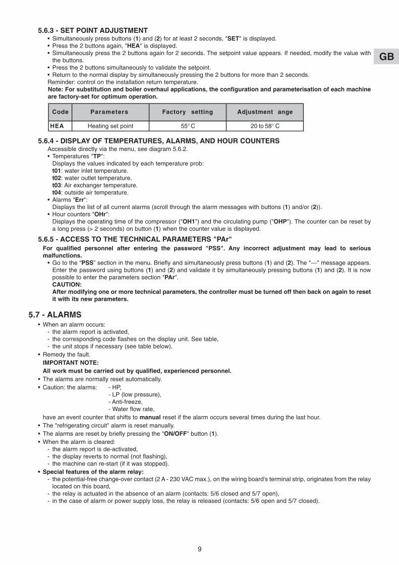
5.6 - PARAMETERS - DISPLAYING AND ADJUSTING5.6.1 - GENERAL
• Parameter access is structured within a multi-level menu, see the diagram below. Simultaneously pressing the"ON/OFF" (1) and "Mode" (2) buttons for a brief moment (less than 2 seconds) gives access to the next level.Simultaneously pressing for a long moment (longer than 2 seconds) turns you to the previous level.
• Button (1) or button (2) is used to scroll through the entries ("Label") within the same level or to increase or decrease aparameter value.
5.6.2 - PARAMETER ACCESS DIAGRAM
t < 2 sec. --> Upper level t > 2 sec. --> Return to the previous level
(*) Accessible to qualified personnel only after entering the password (PSS).
Note 1: Indicator lamps (6), (7), (8) flash when levels 1 and above are accessed.Note 2: The normal display (level 0) returns automatically after 5 minutes if no buttons are pressed.
Level 0Normal display Level 1 Level 2 Level 3 Level 4
Temperature S1Alarm active
Set value SETHeating setpointHEA
Setpoint value
Temperature probes TP
Probe code t01…t04 Temperature value
Alarms Err Alarm code E00...
Digital inputs Id (*) Input code 01… input status
Parameters PAr (*) Config. para. CnFParameters codesH01…
Parameter value
Compressorparameter CP
Parameters codesC01…
Parameter value
Fan parameter FAnParameters codesF01…
Parameter value
Alarm parameterALL
Parameters codesA01…
Parameter value
Pump para. PUPParameters codesP01…
Parameter value
Frost. para. FroParameters codesr01…
Parameter value
Defrost. para. dFrParameters codesd01…
Parameter value
Password PSS Password value
Hour counters OHr Comp. counter 1 OH1 Counter value
Pump counter OHP Counter value
GB
9
5.6.3 - SET POINT ADJUSTMENT• Simultaneously press buttons (1) and (2) for at least 2 seconds, "SET" is displayed.• Press the 2 buttons again, "HEA" is displayed.• Simultaneously press the 2 buttons again for 2 seconds. The setpoint value appears. If needed, modify the value with
the buttons. • Press the 2 buttons simultaneously to validate the setpoint.• Return to the normal display by simultaneously pressing the 2 buttons for more than 2 seconds.Reminder: control on the installation return temperature.Note: For substitution and boiler overhaul applications, the configuration and parameterisation of each machineare factory-set for optimum operation.
5.6.4 - DISPLAY OF TEMPERATURES, ALARMS, AND HOUR COUNTERSAccessible directly via the menu, see diagram 5.6.2.• Temperatures "TP":
Displays the values indicated by each temperature prob:t01: water inlet temperature.t02: water outlet temperature.t03: Air exchanger temperature.t04: outside air temperature.
• Alarms "Err":Displays the list of all current alarms (scroll through the alarm messages with buttons (1) and/or (2)).
• Hour counters "OHr":Displays the operating time of the compressor ("OH1") and the circulating pump ("OHP"). The counter can be reset bya long press (> 2 seconds) on button (1) when the counter value is displayed.
5.6.5 - ACCESS TO THE TECHNICAL PARAMETERS "PAr"For qualified personnel after entering the password "PSS". Any incorrect adjustment may lead to seriousmalfunctions.
• Go to the “PSS” section in the menu. Briefly and simultaneously press buttons (1) and (2). The "---" message appears.Enter the password using buttons (1) and (2) and validate it by simultaneously pressing buttons (1) and (2). It is nowpossible to enter the parameters section "PAr".CAUTION: After modifying one or more technical parameters, the controller must be turned off then back on again to resetit with its new parameters.
5.7 - ALARMS• When an alarm occurs:
- the alarm report is activated,- the corresponding code flashes on the display unit. See table,- the unit stops if necessary (see table below).
• Remedy the fault.IMPORTANT NOTE: All work must be carried out by qualified, experienced personnel.
• The alarms are normally reset automatically.• Caution: the alarms: - HP,
- LP (low pressure),- Anti-freeze,- Water flow rate,
have an event counter that shifts to manual reset if the alarm occurs several times during the last hour.• The "refrigerating circuit" alarm is reset manually.• The alarms are reset by briefly pressing the "ON/OFF" button (1).• When the alarm is cleared:
- the alarm report is de-activated,- the display reverts to normal (not flashing),- the machine can re-start (if it was stopped).
• Special features of the alarm relay:- the potential-free change-over contact (2 A - 230 VAC max.), on the wiring board's terminal strip, originates from the relay
located on this board,- the relay is actuated in the absence of an alarm (contacts: 5/6 closed and 5/7 open),- in the case of alarm or power supply loss, the relay is released (contacts: 5/6 open and 5/7 closed).
Code Parameters Factory setting Adjustment ange
HEA Heating set point 55° C 20 to 58° C
GB
10
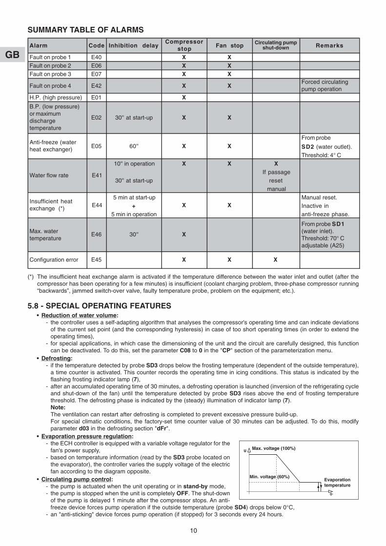
SUMMARY TABLE OF ALARMS
(*) The insufficient heat exchange alarm is activated if the temperature difference between the water inlet and outlet (after thecompressor has been operating for a few minutes) is insufficient (coolant charging problem, three-phase compressor running“backwards”, jammed switch-over valve, faulty temperature probe, problem on the equipment; etc.).
5.8 - SPECIAL OPERATING FEATURES• Reduction of water volume:
- the controller uses a self-adapting algorithm that analyses the compressor's operating time and can indicate deviationsof the current set point (and the corresponding hysteresis) in case of too short operating times (in order to extend theoperating times),
- for special applications, in which case the dimensioning of the unit and the circuit are carefully designed, this functioncan be deactivated. To do this, set the parameter C08 to 0 in the "CP" section of the parameterization menu.
• Defrosting:- if the temperature detected by probe SD3 drops below the frosting temperature (dependent of the outside temperature),
a time counter is activated. This counter records the operating time in icing conditions. This status is indicated by theflashing frosting indicator lamp (7),
- after an accumulated operating time of 30 minutes, a defrosting operation is launched (inversion of the refrigerating cycleand shut-down of the fan) until the temperature detected by probe SD3 rises above the end of frosting temperaturethreshold. The defrosting phase is indicated by the (steady) illumination of indicator lamp (7).Note: The ventilation can restart after defrosting is completed to prevent excessive pressure build-up.For special climatic conditions, the factory-set time counter value of 30 minutes can be adjusted. To do this, modifyparameter d03 in the defrosting section "dFr".
• Evaporation pressure regulation:- the ECH controller is equipped with a variable voltage regulator for the
fan's power supply,- based on temperature information (read by the SD3 probe located on
the evaporator), the controller varies the supply voltage of the electricfan according to the diagram opposite.
• Circulating pump control:- the pump is actuated when the unit operating or in stand-by mode,- the pump is stopped when the unit is completely OFF. The shut-down
of the pump is delayed 1 minute after the compressor stops. An anti-freeze device forces pump operation if the outside temperature (probe SD4) drops below 0°C,
- an "anti-sticking" device forces pump operation (if stopped) for 3 seconds every 24 hours.
Alarm Code Inhibition delayCompressor
stop Fan stop Circulating pumpshut-down Remarks
Fault on probe 1 E40 X XFault on probe 2 E06 X XFault on probe 3 E07 X X
Fault on probe 4 E42 X XForced circulatingpump operation
H.P. (high pressure) E01 X
B.P. (low pressure)or maximumdischargetemperature
E02 30'' at start-up X X
From probe
SD2 (water outlet).
Threshold: 4° C
10'' in operation X X XIf passage
30'' at start-up reset
manual
5 min at start-up Manual reset.
+ Inactive in
5 min in operation anti-freeze phase.
Configuration error
Anti-freeze (waterheat exchanger)
Water flow rate
Insufficient heatexchange (*)
Max. watertemperature
E45 X X X
E46 30'' X
From probe SD1(water inlet).Threshold: 70° Cadjustable (A25)
E41
X XE44
E05 60'' X X
Max. voltage (100%)
Min. voltage (60%)Evaporationtemperature
GB
11
• Condensate tank heating cord control:- Actuated if the outside temperature (probe SD4) drops below 0°C (regardless the unit's operating mode). The "heating
element" indicator light (8) illuminates.• Operating mode selection:
- The regulator is configured in the factory for On/Stand-by control using an external contact.- In stand-by mode, the circulating pump continues to function.
Note:It is possible to shut the unit down completely (circulating pump stopped) by pressing the ON/OFF button (1).
- This configuration is adapted to system applications,
- For other applications, complete shutdown (“OFF”) by remote contact (instead of stand-by) can be achieved bymodifying the configuration.
In the "CnF" configuration section, change the parameter H20 from 7 (remote stand-by) to 4 (remote OFF). In thecase of remove "OFF" complete shut-down, the display is off. Only the decimal indicator lamp flashes.The stand-by mode is indicated by the extinction of the heating mode indicator lamps.
• Pre-ventilation:- Generally speaking, in order to condition the air heat exchanger, the fan always starts at full speed a few seconds before
the compressor.• Anti short-cycle time delays:
- The compressor control features a time delay system in order to respect:• a maximum number of starts per hour (10),• a minimum stop time.
• Cycle inversion valve:- The valve is actuated during defrost cycles.
• Control hysteresis:- See the operating diagrams in paragraph 5.4.- The factory setting for hysteresis in heating mode is 4k. Modification is possible. To do this, modify parameter C04
(heating hysteresis) in the compressor section "CP".
6.1 - WATER CONNECTION HOSES• Length 1 m, insulated, female:
- Ø 1” code 70600055 for PHTJ 14 and 19.
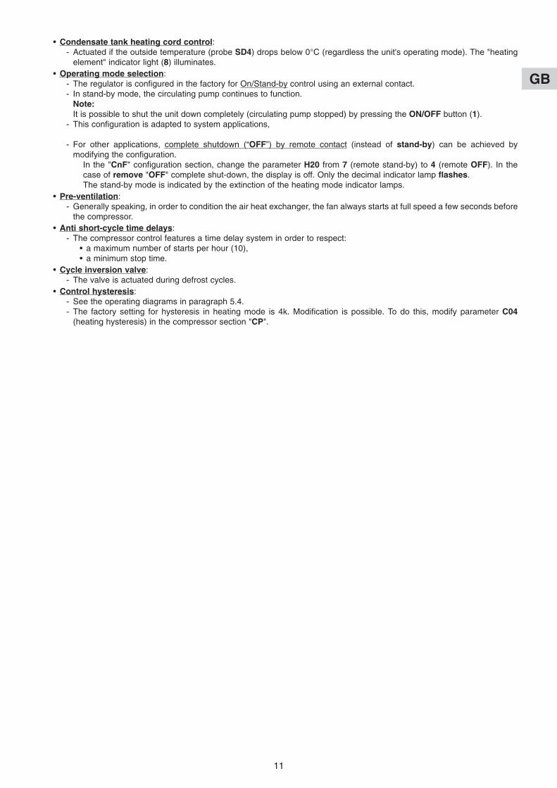
6.2 - REMOTE CONTROL• Code 70250055.• The functions and display are exactly the same as those on controller.
• The only difference concerns the buttons and which areseparated by the “ON/OFF” and “Mode” buttons.
• Reminder: the parameters are accessed by simultaneously pressing the“ON/OFF” and “Mode” buttons.
• The controller is designed to be installed inside sheltered rooms.
• Connection:- the control is delivered with a connecting it to the “ECH” controller,- to extend the link, max. length: 100 meters, use twisted pair shielded
cable with a cross section of at least 0.5 mm2 (shielding of the groundon unit side).
CAUTION:Do not route this cable near power cables. The operation must take performed with the unit's power supply offand locked out.
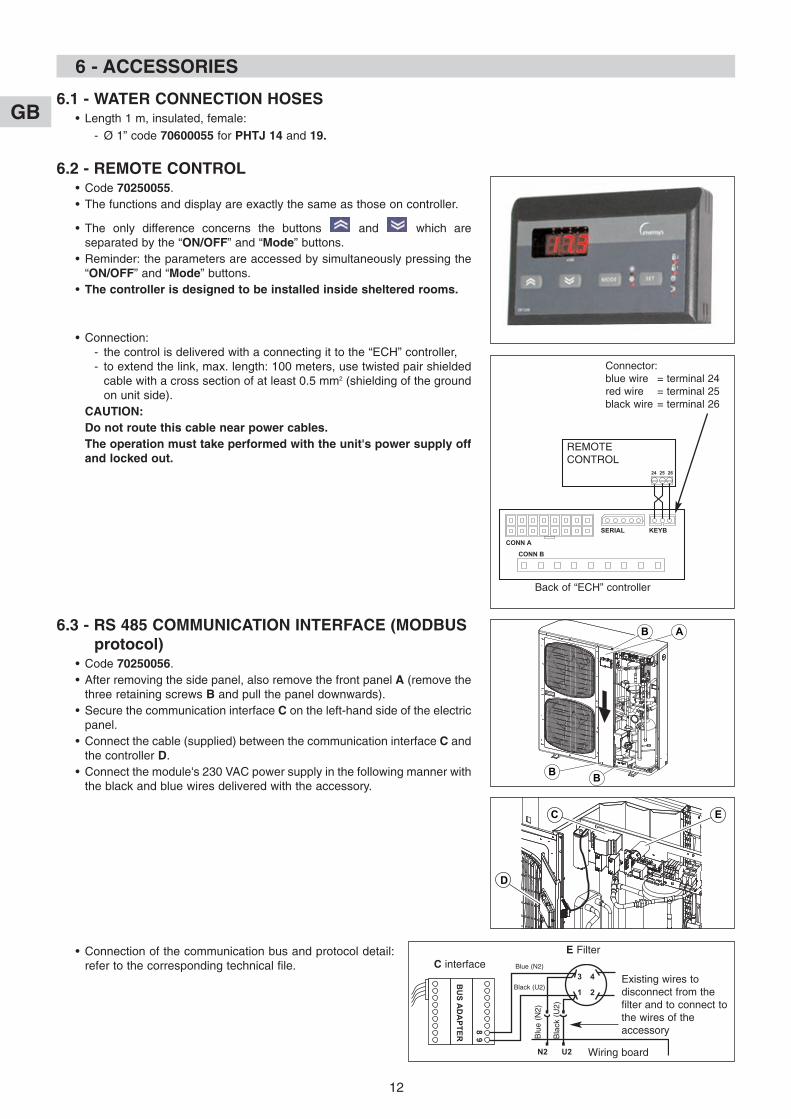
6.3 - RS 485 COMMUNICATION INTERFACE (MODBUSprotocol)
• Code 70250056.• After removing the side panel, also remove the front panel A (remove the
three retaining screws B and pull the panel downwards).• Secure the communication interface C on the left-hand side of the electric
panel.• Connect the cable (supplied) between the communication interface C and
the controller D.• Connect the module's 230 VAC power supply in the following manner with
the black and blue wires delivered with the accessory.
• Connection of the communication bus and protocol detail:refer to the corresponding technical file.
GB
12
3 4
1
N2 U2
98
BU
S A
DA
PT
ER
2
B A
B B
C
D
E
E FilterC interface Blue (N2)
Black (U2)Existing wires todisconnect from thefilter and to connect tothe wires of theaccessory
Blu
e (N
2)
Bla
ck (
U2)
Wiring board
CONN A
CONN B
SERIAL KEYB
24 25 26
Connector:blue wire = terminal 24red wire = terminal 25black wire = terminal 26
Back of “ECH” controller
REMOTECONTROL
6 - ACCESSORIES
GB
13
7 - STARTING
Before carrying out any work on the installation, make sure that it is switched off and that access to it is prevented.Any work must be carried out by personnel qualified and authorised to work on this type of machine.
IMPORTANT NOTE
7.1 - CHECK• That hydraulic connections are properly tight and that the hydraulic circuit functions correctly:
- purge of circuits,- position of valves,- hydraulic pressure (2 bar).
• That there are no leaks.• That the machine is stable.• That the power cables are well fixed to their connection terminals. Terminals that are poorly tightened may cause
overheating and malfunctions.• That the electric cables are well insulated from any sections of sheet metal or metal parts which could damage them.• That probe, control and power cables are properly separated.• That the machine is earthed.• That there are neither tools nor other foreign objects in the units.
7.2 - WATER QUALITY• In order for the heat pump to operate under good conditions and provide optimum performance, it is essential to ensure that
the system’s water circuit is clean. If the water circuit becomes clogged, this will significantly affect the machine’sperformance. The circuit must therefore be cleaned with suitable products in compliance with current standards as soon asit is installed, both for new and renovation work.We recommend the use of products which are compatible with all metals and synthetic materials and approved by officialbodies.Recommendations regarding water quality:
- PH: 6 to 9- TH: 10 to 20°F- Dry material in suspension: < 2 g/l- Granulometry: < 0.4 mm
- Chloride: 50 mg/l maximum- Conductivity: 50 to 500 µS/cm2
- Resistivity: 1 to 10 kΩ- Fibre: no fibres
Any disorder which may occur on our machines due to the poor quality of the fluid in the installation will not be covered bythe TECHNIBEL warranty.
7.3 - STARTING-UP THE UNIT• Power up the unit.• Turn the water on.• Start the appliance (see paragraph 5).
CAUTION: On three-phase units, make sure that the phase rotation order is correct. If the rotation order is not respected, thecompressor will turn backwards (and make an abnormal noise). To fix this, simply invert the 2 phases.
7.4 - CHECKS TO BE MADE• Water flow-rate.• The generator is equipped with 1/4 SAE pressure taps at the circulator inlet and outlet, to enable the pressure drop to be
measured using a hydraulic pressure gauge. Use the circulator curves in paragraph 10 to find the water flow rate. Note:In order for the device to operate correctly, there must be a constant flow of water. It must correspond to the datagiven in the circulator graphs (in paragraph 10), particularly for the high temperature application (water outletgreater than 55° C).
• Hydraulic circuit pressures.• Control system operation.• Sealing of the cooling circuit (according to the decree of 7th May 2007).
IMPORTANT:If antifreeze is added (monopropylene glycol), a minium rate of 15% to 20% is needed to avoid any risk of corrosion.
• The LP pressure switch cuts at 0.5 bar.• The HP pressure switch cuts at 29 bar.
GB
14
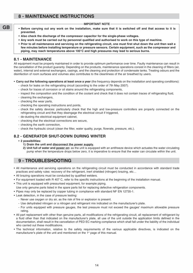
8 - MAINTENANCE INSTRUCTIONS
8.1 - MAINTENANCEAll equipment must be properly maintained in order to provide optimum performance over time. Faulty maintenance can result inthe cancellation of the product guaranty. Depending on the products, maintenance operations consist in the cleaning of filters (air,water), internal and external exchangers, casings, and the cleaning and protection of condensate tanks. Treating odours and thedisinfection of room surfaces and volumes also contributes to the cleanliness of the air breathed by users.
• Carry out the following operations at least once a year (the frequency depends on the installation and operating conditions):- check for leaks on the refrigerating circuit (according to the order of 7th May 2007).- check for traces of corrosion or oil stains around the refrigerating components,- inspect the composition and the condition of the coolant and check that it does not contain traces of refrigerating fluid,- cleaning the exchangers,- checking the wear parts,- checking the operating instructions and points,- check the safety devices: particularly check that the high and low-pressure controllers are properly connected on the
refrigerating circuit and that they disengage the electrical circuit if triggered,- de-dusting the electrical equipment cabinet,- checking that the electrical connections are secure,- checking the earth connection,- check the hydraulic circuit (clean the filter, water quality, purge, flowrate, pressure, etc.).
8.2 - GENERATOR SHUT-DOWN DURING WINTER• 2 possibilities:
1) Drain the unit and disconnect the power supply.2) Unit full of water and power on: as the unit is equipped with an antifreeze device which actuates the water circulating
pump when the temperature drops below zero, it is imperative to ensure that the water can circulate within the unit.
• Before carrying out any work on the installation, make sure that it is switched off and that access to it isprevented.
• Also check the discharge of the compressor capacitor for the single-phase voltages.• Any work must be carried out by personnel qualified and authorised to work on this type of machine.• Prior to all maintenance and servicing on the refrigerating circuit, one must first shut down the unit then wait a
few minutes before installing temperature or pressure sensors. Certain equipment, such as the compressor andpiping, may reach temperatures above 100°C and high pressures may lead to serious burns.
IMPORTANT NOTE
9 - TROUBLESHOOTING
• All maintenance and servicing operations on the refrigerating circuit must be conducted in accordance with standard tradepractices and safety rules: recovery of the refrigerant, inert shielded (nitrogen) brazing, etc…
• All brazing operations must be conducted by qualified welders.• For equipment loaded with R 407 C, refer to the specific instructions at the beginning of the installation manual.• This unit is equipped with pressurised equipment, for example piping.
Use only genuine parts listed in the spare parts list for replacing defective refrigeration components. • Pipes may only be replaced by copper tubing in compliance with standard NF EN 12735-1.• Leak detection, in the case of pressure testing:
- Never use oxygen or dry air, as the risk of fire or explosion is present.- Use dehydrated nitrogen or a nitrogen and refrigerant mix indicated on the manufacturer's plate.- For units equipped with pressure gauges, the test pressure must not exceed the gauges' maximum allowable pressure
rating.• All part replacement with other than genuine parts, all modifications of the refrigerating circuit, all replacement of refrigerant by
a fluid other than that indicated on the manufacturer's plate, all use of the unit outside the application limits defined in thedocumentation, shall result in the cancellation of PED EC marking compliance which shall fall under the liability of the individualwho carried out these modifications.
• The technical information, relative to the safety requirements of the various applicable directives, is indicated on themanufacturer's plate of the unit and mentioned on the 1st page of this manual.
GB
15
0
20
40
60
80
100
120
1 1.5 2 2.5 3
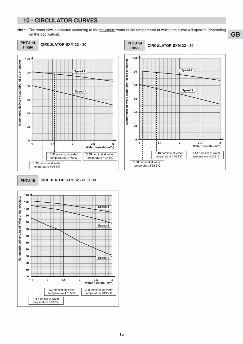
10 - CIRCULATOR CURVES
PHTJ 14single
CIRCULATOR SXM 32 - 80
PHTJ 19 CIRCULATOR SXM 32 - 80 OEM
Man
om
etri
c d
eliv
ery
hea
d (
kPa)
of
the
circ
ula
tor
Speed 1
Speed 2
2.55 nominal at watertemperature 40/45°C
1.55 nominal at watertemperature 47/55°C
Note: The water flow is selected according to the maximum water outlet temperature at which the pump will operate (dependingon the application).
1.25 nominal at watertemperature 55/65°C
Water flowrate (m3/h)
0
20
40
60
80
100
120
1 1.5 2 2.5 3
PHTJ 14 three CIRCULATOR SXM 32 - 80
Man
om
etri
c d
eliv
ery
hea
d (
kPa)
of
the
circ
ula
tor
Speed 1
Speed 2
2.43 nominal at watertemperature 40/45°C
1.43 nominal at watertemperature 47/55°C
1.08 nominal at watertemperature 55/65°C
Water flowrate (m3/h)
0
10
20
30
40
50
60
70
80
90
100
110
120
1.5 2 2.5 43 3.5
Speed 1
Man
om
etri
c d
eliv
ery
hea
d (
kPa)
of
the
circ
ula
tor
Speed 2
Speed 3
1.8 nominal at watertemperature 55/65°C
3,45 nominal at watertemperature 40/45°C
2.3 nominal at watertemperature 47/55°C
Water flowrate (m3/h)
GB
16
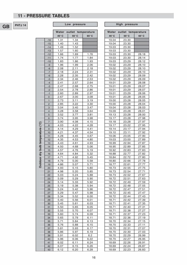
11 - PRESSURE TABLES
PHTJ 14
45° C 55° C 65° C 45° C 55° C 65° C
-16 1.31 1.34 19.04 23.30-15 1.40 1.43 19.04 23.30-14 1.49 1.52 19.03 23.30-13 1.57 1.60 19.03 23.30-12 1.66 1.69 1.76 19.03 23.30 28.18-11 1.74 1.77 1.84 19.03 23.30 28.14-10 1.83 1.86 1.93 19.03 23.29 28.12-9 1.96 1.99 2.06 19.02 23.29 28.10-8 2.08 2.11 2.18 19.02 23.29 28.10-7 2.18 2.24 2.31 19.02 23.29 28.10-6 2.28 2.35 2.42 19.02 23.29 28.09-5 2.34 2.46 2.53 19.02 23.29 28.09-4 2.41 2.57 2.64 19.01 23.29 28.08-3 2.47 2.68 2.75 19.01 23.29 28.07-2 2.54 2.78 2.86 19.01 23.29 28.07-1 2.60 2.89 2.97 19.01 23.29 28.060 2.67 3.00 3.08 19.01 23.28 28.051 2.73 3.11 3.19 19.00 23.28 28.052 2.85 3.22 3.30 19.00 23.28 28.043 3.04 3.40 3.47 19.04 23.28 28.034 3.28 3.58 3.64 19.09 23.28 28.015 3.52 3.77 3.81 19.13 23.28 28.006 3.74 3.95 3.98 19.17 23.28 27.987 3.90 4.08 4.15 19.18 23.28 27.978 4.03 4.22 4.28 19.17 23.22 27.959 4.14 4.29 4.41 19.14 23.17 27.9410 4.21 4.37 4.54 19.10 23.11 27.9211 4.28 4.45 4.67 19.06 23.05 27.9012 4.35 4.53 4.80 19.03 23.00 27.8913 4.43 4.61 4.93 18.99 22.94 27.8714 4.50 4.68 5.06 18.95 22.89 27.8515 4.57 4.76 5.19 18.92 22.83 27.8316 4.64 4.84 5.32 18.88 22.77 27.8217 4.71 4.92 5.45 18.84 22.72 27.8018 4.79 5.00 5.58 18.80 22.66 27.7819 4.86 5.07 5.71 18.77 22.61 27.7720 4.93 5.15 5.80 18.73 22.55 27.7521 4.98 5.20 5.85 18.73 22.54 27.7122 5.03 5.24 5.88 18.73 22.52 27.6723 5.09 5.29 5.90 18.72 22.51 27.6324 5.14 5.33 5.92 18.72 22.49 27.5925 5.19 5.38 5.94 18.72 22.48 27.5526 5.24 5.42 5.96 18.72 22.47 27.5127 5.29 5.47 5.98 18.72 22.45 27.4728 5.34 5.52 6.00 18.72 22.44 27.4329 5.40 5.56 6.01 18.71 22.42 27.3930 5.45 5.61 6.03 18.71 22.41 27.3531 5.50 5.65 6.05 18.71 22.40 27.3132 5.55 5.70 6.07 18.71 22.38 27.2733 5.60 5.74 6.09 18.71 22.37 27.2334 5.65 5.79 6.11 18.71 22.36 27.1935 5.71 5.84 6.13 18.70 22.34 27.1536 5.76 5.88 6.15 18.70 22.33 27.1137 5.81 5.93 6.17 18.70 22.31 27.0738 5.86 5.97 6.19 18.70 22.30 27.0339 5.91 6.02 6.2 18.70 22.29 26.9940 5.96 6.06 6.22 18.70 22.27 26.9541 6.02 6.11 6.24 18.69 22.26 26.9142 6.07 6.15 6.26 18.69 22.24 26.8743 6.12 6.20 6.28 18.69 22.23 26.83
Low pressure High pressure
Water outlet temperature Water outlet temperature
Ou
tdo
or
dry
bu
lb t
emp
erat
ure
(°C
)
GB
17
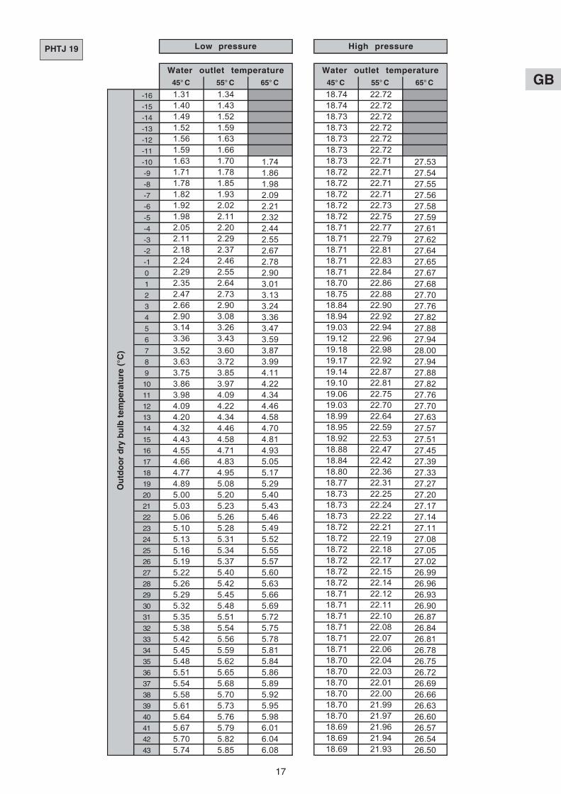
PHTJ 19
45° C 55° C 65° C 45° C 55° C 65° C
-16 1.31 1.34 18.74 22.72
-15 1.40 1.43 18.74 22.72
-14 1.49 1.52 18.73 22.72
-13 1.52 1.59 18.73 22.72
-12 1.56 1.63 18.73 22.72
-11 1.59 1.66 18.73 22.72
-10 1.63 1.70 1.74 18.73 22.71 27.53-9 1.71 1.78 1.86 18.72 22.71 27.54-8 1.78 1.85 1.98 18.72 22.71 27.55-7 1.82 1.93 2.09 18.72 22.71 27.56-6 1.92 2.02 2.21 18.72 22.73 27.58-5 1.98 2.11 2.32 18.72 22.75 27.59-4 2.05 2.20 2.44 18.71 22.77 27.61-3 2.11 2.29 2.55 18.71 22.79 27.62-2 2.18 2.37 2.67 18.71 22.81 27.64-1 2.24 2.46 2.78 18.71 22.83 27.650 2.29 2.55 2.90 18.71 22.84 27.671 2.35 2.64 3.01 18.70 22.86 27.682 2.47 2.73 3.13 18.75 22.88 27.703 2.66 2.90 3.24 18.84 22.90 27.764 2.90 3.08 3.36 18.94 22.92 27.825 3.14 3.26 3.47 19.03 22.94 27.886 3.36 3.43 3.59 19.12 22.96 27.947 3.52 3.60 3.87 19.18 22.98 28.008 3.63 3.72 3.99 19.17 22.92 27.949 3.75 3.85 4.11 19.14 22.87 27.8810 3.86 3.97 4.22 19.10 22.81 27.8211 3.98 4.09 4.34 19.06 22.75 27.7612 4.09 4.22 4.46 19.03 22.70 27.7013 4.20 4.34 4.58 18.99 22.64 27.6314 4.32 4.46 4.70 18.95 22.59 27.5715 4.43 4.58 4.81 18.92 22.53 27.5116 4.55 4.71 4.93 18.88 22.47 27.4517 4.66 4.83 5.05 18.84 22.42 27.3918 4.77 4.95 5.17 18.80 22.36 27.3319 4.89 5.08 5.29 18.77 22.31 27.2720 5.00 5.20 5.40 18.73 22.25 27.2021 5.03 5.23 5.43 18.73 22.24 27.1722 5.06 5.26 5.46 18.73 22.22 27.1423 5.10 5.28 5.49 18.72 22.21 27.1124 5.13 5.31 5.52 18.72 22.19 27.0825 5.16 5.34 5.55 18.72 22.18 27.0526 5.19 5.37 5.57 18.72 22.17 27.0227 5.22 5.40 5.60 18.72 22.15 26.9928 5.26 5.42 5.63 18.72 22.14 26.9629 5.29 5.45 5.66 18.71 22.12 26.9330 5.32 5.48 5.69 18.71 22.11 26.9031 5.35 5.51 5.72 18.71 22.10 26.8732 5.38 5.54 5.75 18.71 22.08 26.8433 5.42 5.56 5.78 18.71 22.07 26.8134 5.45 5.59 5.81 18.71 22.06 26.7835 5.48 5.62 5.84 18.70 22.04 26.7536 5.51 5.65 5.86 18.70 22.03 26.7237 5.54 5.68 5.89 18.70 22.01 26.6938 5.58 5.70 5.92 18.70 22.00 26.6639 5.61 5.73 5.95 18.70 21.99 26.6340 5.64 5.76 5.98 18.70 21.97 26.6041 5.67 5.79 6.01 18.69 21.96 26.5742 5.70 5.82 6.04 18.69 21.94 26.5443 5.74 5.85 6.08 18.69 21.93 26.50
Low pressure High pressure
Water outlet temperature Water outlet temperature
Ou
tdo
or
dry
bu
lb t
emp
erat
ure
(°C
)
GB
18
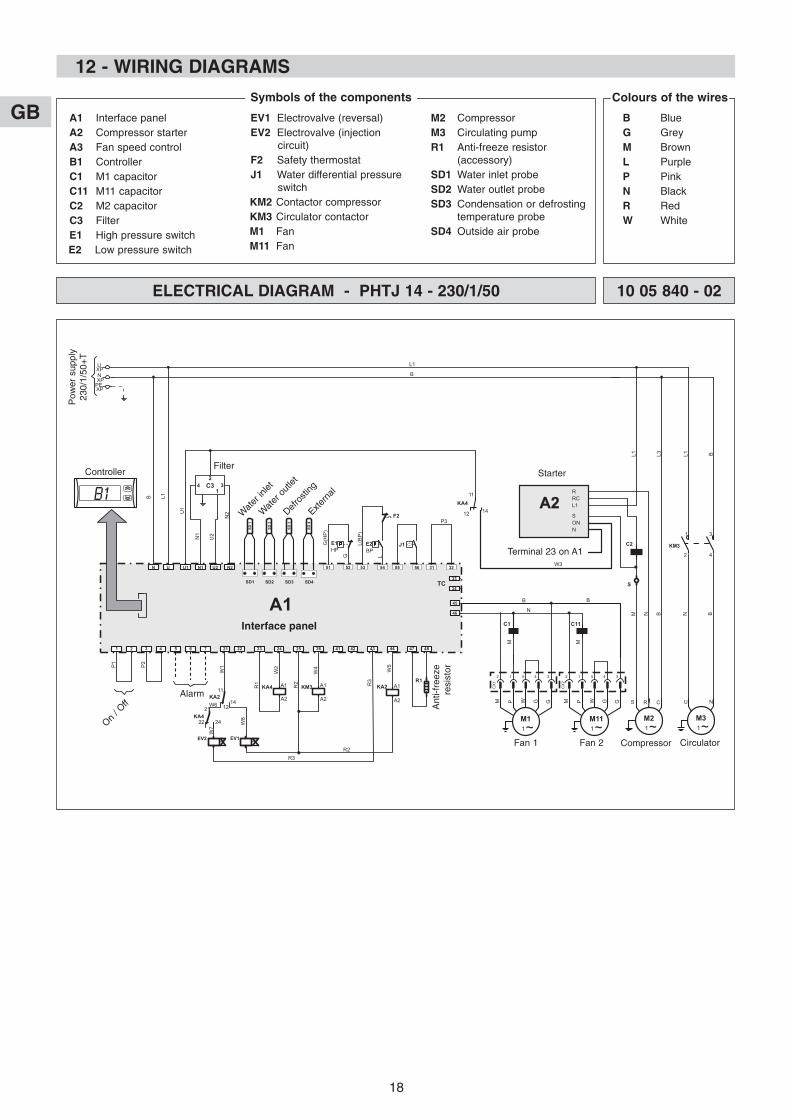
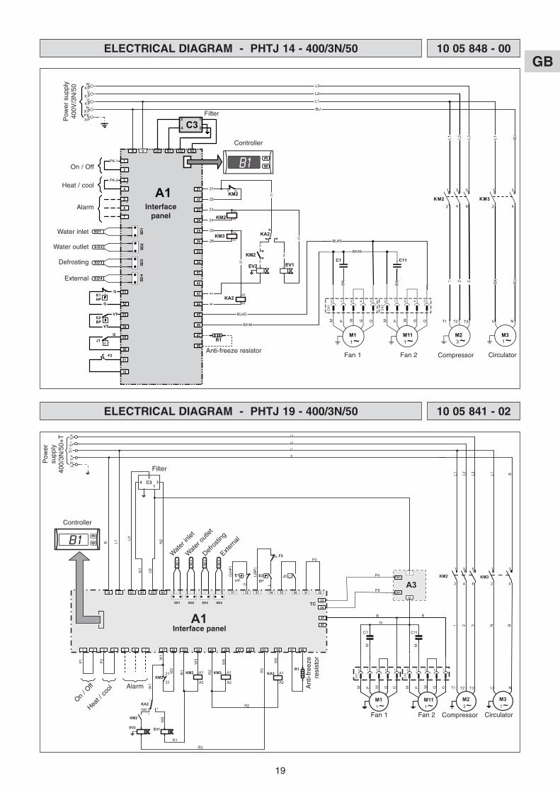
12 - WIRING DIAGRAMS
A1 Interface panelA2 Compressor starterA3 Fan speed controlB1 ControllerC1 M1 capacitorC11 M11 capacitorC2 M2 capacitorC3 FilterE1 High pressure switchE2 Low pressure switch
EV1 Electrovalve (reversal)EV2 Electrovalve (injection
circuit)F2 Safety thermostatJ1 Water differential pressure
switchKM2 Contactor compressorKM3 Circulator contactorM1 FanM11 Fan
M2 CompressorM3 Circulating pumpR1 Anti-freeze resistor
(accessory)SD1 Water inlet probeSD2 Water outlet probeSD3 Condensation or defrosting
temperature probeSD4 Outside air probe
Symbols of the components
B BlueG GreyM BrownL PurpleP PinkN BlackR RedW White
Colours of the wires
M31~
U N
45
1 3
2 4
KM3
M21~
S R C
M N B
L1 L3 L1 B
B
46 N
C1
3231
P3
5655
J1E2BP
5453
L
L(BP)
G
R1
HP
G(HP)
5251
A1
SD 4
SD 3
SD 2
SD 1
U2U1 N1 N2N
13
24
B L1
U2
N2
L1
B
4847
W5
R3
KA2
44434241
R2
KA4 A1
A2
W4
KM3 A1
A2
R1
W2
26252423222175 642 31
P1
P2
NXPPEXP
UXP
M
M11~
P W GM G
2 1 5 4 3
CX1
M111~
P W GM G
2 1 5 4 3
CX2
C11
M
B
E1
U1
N1
N B
U
SD1 SD2 SD3 SD433
34TC
C3
A1
A2
R3
C2
A2A2
W3
RRCL1
SONN
KA411
12 14
S
F2
W8
W6
W1
W7
11
EV1
KA2
1214
EV2
R2
KA421
22 24
ELECTRICAL DIAGRAM - PHTJ 14 - 230/1/50 10 05 840 - 02
Pow
er s
uppl
y23
0/1/
50+
T
Filter
Wat
er in
let
Wat
er o
utlet
Defro
sting
Extern
al
On / O
ffAlarm
Ant
i-fre
eze
resi
stor
Fan 1 Fan 2 Compressor Circulator
Controller
Interface panel
Starter
Terminal 23 on A1
GB
19
ELECTRICAL DIAGRAM - PHTJ 19 - 400/3N/50 10 05 841 - 02
M31~
U N
45
1 3
2 4
KM3
1 3 5
2 4 6
KM2
M23~
T1 T2 T3
1 2 3
L1 L3 L1 B
B
46 N
C1
3231
P3
5655
J1E2BP
5453
L
L(BP)
G
R1
HP
G(HP)
5251
A1
SD 4
SD 3
SD 2
SD 1
U2U1 N1 N2N
13
24
B L1
U2
N2
L1
B
4847
W5
R3
KA2
44434241
R2KM2 A1
A2
W4
KM3 A1
A2
R1
W3
26252423
KM2
W2
W1
21
22
222175 642 31
P1
P2
NXPPEXP
UXP
M
M11~
P W GM G
2 1 5 4 3
CX1
M111~
P W GM G
2 1 5 4 3
CX2
C11
M
B
E1
U1
N1
N B
U
SD1 SD2 SD3
P4
P5
CN1I
CN1
II
A3
SD433
34TC
WXPVXP
L3
L2
L2
C3
A1
A2
R2
F2
W8
W6
EV2
11
KM2
EV1
KA2
12
14
R3
R1
W1
Pow
ersu
pply
400/
3N/5
0+T
Filter
Wat
er in
let
Wat
er o
utlet
Defro
sting
Extern
al
On / O
ff
Heat /
cool Alarm Ant
i-fre
eze
resi
stor
Fan 1 Fan 2 Compressor Circulator
Controller
Interface panel
ELECTRICAL DIAGRAM - PHTJ 14 - 400/3N/50 10 05 848 - 00
1~
P W GM G
2 1 5 4 3
CX2
1~P W GM G
2 1 5 4 3
CX1
1~
U N
1 3
2 4
KM3
3~
T1 T2 T3
NXPPEXP
UXP
U2U1 N1 N2U
SD 1
S D 2
PK-1
SD 3
SD 4
HPE1
BPE2
GJ1 R1
A2
A1KM3
SD2
SD1
SD3
SD4
L 1 L3 L1 BU
BU
L1
23
24
25
26
43
44
BU45
BK46
BN BN
BU45
BK46
G
G
VT
VT
PK-2
1 2 3 BK BU
2
4
VXP
WXP
1 5
2 6
KM2
3
4
L2
A2
A1KM2
1
3
21
22
21 22
A2
A1KA2
25
L2
L3
23
21
14
1213
KM2
N
C1 C11
1
2
3
4
5
6
7
51
52
53
54
55
56
31
32
21
22
23
24
25
26
33
34
41
42
43
44
45
46
47
48
EV2
1111
KM2
EV1
KA21212 1414
1313
1414
F2
A1
C3
M1 M11 M2 M3
Pow
er s
uppl
y40
0V/3
N/5
0
Filter
Water inlet
Water outlet
Defrosting
External
On / Off
Heat / cool
Alarm
Anti-freeze resistorFan 1 Fan 2 Compressor Circulator
Controller
Interfacepanel

F
GB
D
P
I
E

F
GB
D
P
I
E

F
GB
D
P
I
E
Par souci d'amélioration constante, nos produits peuvent être modifiés sans préavis.Due to our policy of continuous development, our products are liable to modification without notice.
Per garantire un costante miglioramento dei nostri prodotti, ci riserviamo di modificarli senza preaviso.En el interés de mejoras constantes, nuestros productos pueden modificarse sin aviso prévio.
Unsere Produkte werden laufend verbessert und können ohne Vorankündigung abgeändert werden.Com o objectivo de uma melhoria constante, os nossos produtos podem ser modificados sem aviso prévio.
R.D. 28 Reyrieux BP 131 01601 Trévoux CEDEX FranceTél. 04 74 00 92 92 - Fax 04 74 00 42 00Tel. 33 4 74 00 92 92 - Fax 33 4 74 00 42 00R.C.S. Bourg-en-Bresse B 759 200 728