Embed Size (px)
Citation preview
. . . . . . . . . .
. . . . . . . . . .
PPMM44DD FFiinnaall RReeppoorrtt
CCIIFFEE TTeecchhnniiccaall RReeppoorrtt NNuummbbeerr 114433 BByy MMaarrttiinn FFiisscchheerr aanndd CCaallvviinn KKaamm
OOccttoobbeerr 22000022
SSeennaattee PPrrooppeerrttiieess
OOllooff GGrraannlluunndd OOyy
YYIITT CCoorrppoorraattiioonn
FFiinnllaanndd
CCIIFFEE,, SSttaannffoorrdd UUnniivveerrssiittyy
UUnniitteedd SSttaatteess ooff AAmmeerriiccaa
PM4D Final Report Page 1 October 2002
We would like to express our gratitude to the Finnish National Technology Agency (TEKES) for funding this research project through the Information Networking in Construction (VERA) Program. We also thank Senate Properties, Insinööritoimisto Olof Granlund Oy, YIT Corporation from Finland; and the Center for Integrated Facility Engineering (CIFE) in Stanford University, USA, for their contributions to this research and report.
In particular, we are thankful to Seppo Lehto, former development manager of Senate Properties, for his vision and proactive coordination of the project team; Auli Karjalainen, project manager of the Helsinki University of Technology Auditorium-600 (HUT-600) project, for sharing her valuable experience from the HUT-600 project; as well as Juha Muttilainen, Senate Properties, for his technical expertise.
The enthusiastic involvement from the management, design department, and research and development department team from Granlund contributed tremendously to the successful completion of this PM4D project and report. We especially value Reijo Hänninen, managing director of Granlund, for his leadership; Markku Jokela, manager of Granlund’s research and development department, for his detailed and insightful feedback during all phases of the project; Tuomas Laine, Antti Karola, Erkki Finni, Paavo Tikkanen, Tero Järvinen, Sanna Forsman and their colleagues from Granlund for their technical support.
Along with Olli Nummelin, Susanne Backas, and Veli-Pekka Keisu, the passion from Dr. Jarmo Laitinen, Customer Solutions from Solibri, Inc. and former research and development manager of YIT Corporation, has enhanced our study from the construction planning and management perspective. Jyrki Iso-Aho, project architect of the HUT-600 project, and Päivi Vaheri contributed critical product modeling application experience from A-Konsultit Oy—an architectural design firm that has accumulated over 13 years of design practice with 3D object models. In addition, we thank the Experimental Virtual Environment research team from HUT for sharing their immersive virtual reality facility, Magnus Malmverg Consulting Engineers Ltd. for explaining the structural challenges of the project, and Rapal Oy for illustrating the work process of the Kronodoc project databank.
We enjoyed many enlightening discussions with our research partners——Arto Kiviniemi, Tapio Koivu, and visiting fellow Yoshinobu Adachi—from VTT in Finland. Last but not the least, we are indebted to Dr. John Kunz and our colleagues from CIFE in Stanford University for objectively assessing state-of-the-art technologies in the building design and construction practice.
Martin Fischer Director, Center for Integrated Facility Engineering Associate Professor of Civil and Environmental Engineering and (by courtesy) Computer Science Stanford University, USA Calvin Kam Graduate Research Assistant Center for Integrated Facility Engineering Stanford University, USA
Acknowledgements
PM4D Final Report Page 2 October 2002
Chapter 1 Executive Summary 4
Chapter 2 Report Overview 7
2.1 Report Objectives 7 2.2 Audience 7 2.3 Report Organization 8
Chapter 3 Project Background 9
3.1 Project Introduction 9 3.2 Project Stakeholders 9 3.3 Project Challenges 10 3.4 Conventional Practices versus PM4D Approach 10
Chapter 4 PM4D Approach and Processes 12
4.1 PM4D Approach 12 4.1.1 Organization of Project Team 13 4.1.2 Quality of Design and Construction Services 13 4.1.3 Decision Support 13 4.1.4 Information Sharing 14 4.2 PM4D Processes 16 4.2.1 Product Modeling Exchanges 17 4.2.2 Thermal Design and Analyses 17 4.2.3 Life-Cycle Analyses 17 4.2.4 IFC Exchanges 18 4.2.5 Lighting Design 18 4.2.6 4D Visualization 19
4.2.7 Virtual Reality Visualization 19
Chapter 5 Benefits from PM4D Approach 20
5.1 Benefits of Object-Oriented Product Modeling Approach 21 5.1.1 Architectural Design 21 5.1.2 Mechanical Design 23 5.1.3 Construction Planning 24 5.2 Benefits of the IFC Interoperability Standard 25 5.3 Benefits of Thermal Simulations 28 5.3.1 Comfort and Energy Simulation 28 5.3.2 Computational Fluid Dynamics 29
Content
PM4D Final Report Page 3 October 2002
Chapter 5 Benefits from PM4D Approach (Continued)
5.4 Benefits of Visualizations 30 5.4.1 Lighting Visualization 30 5.4.2 Spatial Visualization 31 5.4.3 4D Visualization 32 5.5 Benefits of Online Extranet 33 5.6 Benefits of Life-Cycle Analyses 33 5.6.1 Life-Cycle Cost Analysis 34 5.6.2 Life-Cycle Environmental Impact Analysis 34
Chapter 6 Barriers to Extending PM4D Benefits 36
6.1 Product Model Sharing 37 6.1.1 Lack of Modeling Guidelines and Motivations 37 6.1.2 Application-Specific Inputs/Outputs 38 6.1.3 Time-Consuming One-Way Conversion Processes 39 6.2 IFC Interoperability Standard 40 6.2.1 Geometric Misrepresentation by Middleware and Software 40 6.2.2 Loss of Object Information 41 6.2.3 Confusion in Interdisciplinary Revision 41 6.2.4 Large File Size 41
Chapter 7 Recommendations and Conclusions 42
7.1 Recommendations 42 7.1.1 Building Owners 42 7.1.2 Designers and Builders 42 7.1.3 Researchers 43 7.1.4 Software Developers 43 7.1.5 All Parties 44 7.2 Conclusions 44 7.2.1 Implications of Pilot Industrial Application of IFC’s 44 7.2.2 Capitalize on Early Project Opportunities 44
References 46
Final Thoughts from Project Participants 47
Contacts 49
PM4D Final Report Page 4 October 2002
Introduction
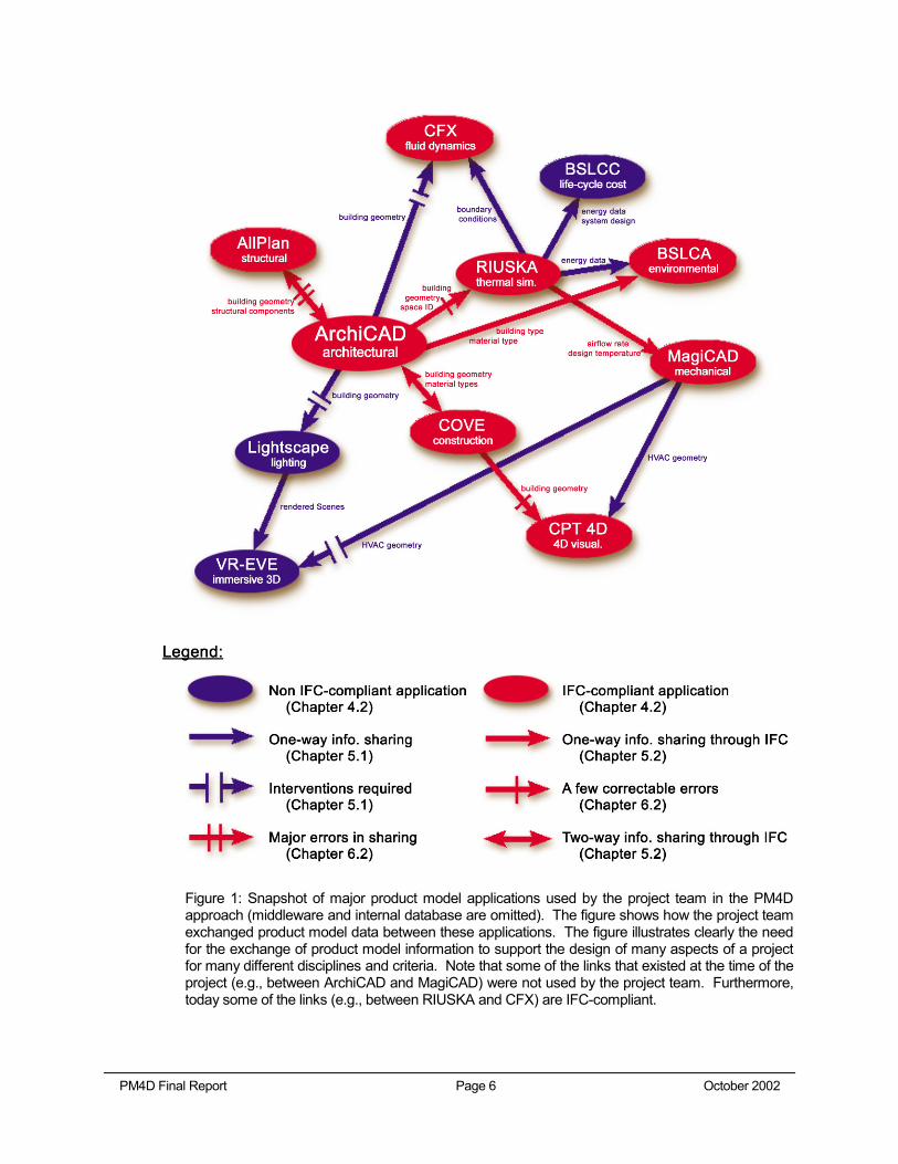
This Product Model and Fourth Dimension (PM4D) report presents the findings from the design and construction of the Helsinki University of Technology Auditorium Hall 600 (HUT-600) in Finland. Running simultaneously with the design and construction of the HUT-600 project, an international research partnership extensively applied the product modeling approach, tested the Industry Foundation Classes (IFC) interoperability standards, and employed an array of design, visualization, simulation, and analysis tools on the 17-month, USD $5-million capital project. Through our dissemination of project experiences and analytical results, we hope that building owners, end-users, and project teams will take advantage of the current capabilities and benefits of the PM4D Approach, which leverages commercially available state-of-the-art analytical and visualization tools to optimize the design, construction, and operation of a proposed facility during early project phases. Figure 1 shows the software tools that were used by the project participants involved in this research and shows the information that was exchanged between these tools via product models based on open (IFC) and proprietary standards. In this research, we have documented cultural, technological, and business barriers to the PM4D Approach.
PM4D Approach
The HUT-600 project team used the following PM4D Approach: They constructed and maintained object-oriented product models with explicit knowledge of building components, spatial definitions, material composition, and other parametric properties. Only with this product modeling approach could the team leverage the object intelligence from the 3D models for data interoperability. These product modeling and interoperability approaches eliminated the inefficiency and risks of data re-entry in conventional practice. The PM4D Approach was crucial for generating reliable and quick cost estimates, construction schedules, comfort designs, energy analyses, environmental reports, and life-cycle cost studies. Furthermore, the approach allowed the project team to utilize visualization tools to review spatial designs in virtual walk-throughs, compare lighting schemes in photo-realistic renderings, and comprehend construction sequences in 4D animations, all leveraging the same electronic design information.
Major Benefits
During the early schematic phase, object-oriented modeling software and IFC’s allowed the project team to shorten the time for design iteration, develop a reliable budget for effective cost control, and eliminate the need to re-enter geometric data, thermal values, and material properties as different disciplines contributed to the design progress. Additionally, visualization tools such as photo-realistic rendering software, Virtual Reality-Experimental Virtual Environment (VR-EVE) fostered early communication among the end-users, owners and the project team, who then captured valuable inputs and effectively translated the client’s intent into long term values. Building on the resulting efficiency and time-savings, the project team was able to conduct a variety of in-depth life-cycle studies and alternative comparisons on thermal performance, operation costs, energy consumption, and environmental impacts. Compared to a conventional approach, these relatively seamless data exchange and technology tools substantially expedited design and improved the quality of interdisciplinary collaboration. The PM4D Approach empowered the building owners to better align the long-term facility values with their strategic plans.
Chapter 1 Executive Summary
PM4D Final Report Page 5 October 2002
Major Barriers to Extending PM4D Benefits
As desired, most PM4D benefits occurred during the early design phase. Even though the PM4D Approach improved upon conventional practices in terms of design quality, project risks, and life-cycle values, we encountered technological, cultural, and business barriers to extending the benefits of PM4D Approach. Project participants in the HUT-600 project could have enjoyed further benefits if product modeling tools supported revision-handling, two-way exchanges, simpler mapping of data formats from exporting to importing applications, and if IFC-compliant software tools were extensible and robust. Culturally, 4D technology could have introduced additional analytical benefits beyond its current utilization if it had been conducted earlier during the preconstruction phase. The online project extranet (also called project databank in this report), if developed optimally, would have made information exchanges more efficient during the construction documentation phase. At the same time, building owners and designers could have exploited business opportunities for the architects’ role in developing and coordinating a sharable product model.
Conclusions and Recommendations
Based on experiences from the HUT-600 project, we conclude that the PM4D Approach helps expedite conventional design practices and promote life-cycle approaches. Project examples demonstrate that owners could choose among comprehensive life-cycle alternatives, end-users could provide input to the facility design in a timely manner, and project team members could differentiate themselves from their competitors with higher efficiency, quality, and more effective application of their expertise. Most participants in this project were surprised by the large number of design, engineering, and analysis tasks that can be supported productively with product models today. Figure 1 shows that many software tools were able to import IFC-based and/or non IFC-based product models for many different disciplines and diverse criteria. However, Figure 1 also shows that the exchange of product model information based on an open standard like IFC is not yet as mature and widespread as needed in practice. One should also note that the use of IFC-based product models worked quite well in the schematic design phase of the project. However, in the later project phases, IFC-based product models were not as effective a means as proprietary information formats to exchange data between software tools. On this project, the IFC standard 1.5.1 was used; recently published standards 2.0 and 2.x address some of the shortcomings of IFC-based product models found in this research. One would also expect that some of the software-based limitations have been ironed out by the vendors by now.
The product modeling and information standards community has long touted the advantages of supporting the many software tools used on projects with a common core model. However, we are still lacking a validated specification for the content of such a core model. Therefore, one of the specific goals of the research was to study whether such a core model exists, i.e., emerges through the team’s experience in using product models to share data, and if it exists, what type of information is part of the core model. Figure 1 and the experience from this research show that the building geometry, material types, and space identifier (or id) are part of a core model. On the other hand, the architect had to expend significant effort to adjust the ‘core’ model to support the different needs of the various disciplines. Furthermore, Figure 1 also shows that, in addition to the 3D core model, there appear to exist discipline-specific models, such as the thermal model. To exploit the potential benefits of the PM4D Approach further, we recommend that researchers and software developers focus their efforts on partial model exchanges, product model servers, better defining “core” versus “discipline-specific” product models, and developing more reliable and extensible tools.
PM4D Final Report Page 6 October 2002
Figure 1: Snapshot of major product model applications used by the project team in the PM4D approach (middleware and internal database are omitted). The figure shows how the project team exchanged product model data between these applications. The figure illustrates clearly the need for the exchange of product model information to support the design of many aspects of a project for many different disciplines and criteria. Note that some of the links that existed at the time of the project (e.g., between ArchiCAD and MagiCAD) were not used by the project team. Furthermore, today some of the links (e.g., between RIUSKA and CFX) are IFC-compliant.
PM4D Final Report Page 7 October 2002
2.1 Report Objectives
Through an in-depth documentation of product modeling applications in a construction project that piloted the use of the Industry Foundation Classes, this report discusses the challenges, benefits, and potential of the PM4D Approach1. The report assesses the implementation mechanism, data standards, and information exchanges of the HUT-600 (Helsinki University of Technology) auditorium extension project from the conceptual design phase through facility construction. The primary objective of this research project was to capture the lessons learned from a practical situation, analyze the potential and limitations of PM4D Processes, assess the value of the PM4D Approach, and provide recommendations for the use and development of product models in future design and construction projects. The objectives of this report are:
• To present the practical benefits, challenges, values, and implications from the PM4D Approach in the HUT-600 project
• To explain how the HUT-600 project team utilized state-of-the-art technologies, information standards, and commercially available software applications to improve the services to their clients
• To document how the PM4D project team leveraged the early project phases to optimize life-cycle decisions
• To evaluate the practical benefits and implementation challenges of the Industry Foundation Classes (IFC) interoperability standard based on this pilot test case
• To identify what research and development (R&D) efforts may be relevant to the obstacles of the PM4D Approach
2.2 Audience
The PM4D Report is written for a diverse group of readers, from researchers to industry practitioners, academics, and software developers:
• Researchers can assess the PM4D implementation strategy, project challenges, lessons learned, and analyses for prioritizing further research directions.
• Industry Practitioners (owners, designers, consultants, and contractors) can better understand the current capabilities and limitations of product model applications in a working project. Practitioners should consider the report’s recommendations when adopting product modeling.
• Academics (faculty members and students) can learn from the integration of a product model in a real construction scenario. This should help foster a closer tie between research efforts and industry needs. The evaluation of state-of-the–art product modeling, visualization, and analysis systems can assist the academic community in anticipating and defining subsequent research needs.
1 Chapter 4 explains the concept of the Product Modeling and the 4th Dimensional (PM4D) Approach.
Chapter 2 Report Overview
PM4D Final Report Page 8 October 2002
• Software Developers can identify the trends of the architecture/ engineering/construction (AEC) profession as well as the specific needs by all its stakeholders. The barriers in industry applications product model and interoperability standard, as well as specific experiences from AEC users may provide developers clues about how best to design and prioritize their products.
2.3 Report Organization
This PM4D Report consists of 7 chapters. Chapter 3 introduces a summary of the project setting. It explains how the PM4D Approach aimed at improving the efficiency and quality of conventional practice. Chapter 4 introduces the concepts of PM4D Approach. Chapter 5 presents the key benefits from the PM4D Approach, and Chapter 6 summarizes the potential for extending the benefits. We conclude with our findings and analyses in Chapter 7, where we distinguish between specific recommendations to building owners, project teams, researchers, and software developers.
PM4D Final Report Page 9 October 2002
3.1 Project Introduction
The Helsinki University of Technology (HUT) is located in the city of Otaniemi, Espoo, Finland. The masterplan and the main buildings of the HUT campus were designed by Finnish architect Alvar Aalto (1898-1976), widely regarded as one of the most prominent architects of the twentieth century. Aalto’s bond with HUT was forged in 1949, when his competition entry was announced as the winning masterplan for the Otaniemi campus. Dominated by the striking form of the two main auditoriums, the main building was completed in 1964.
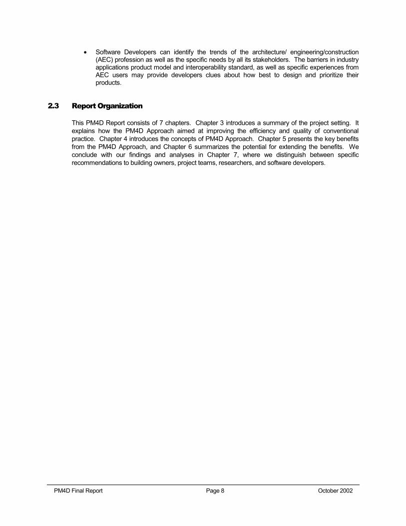
During the next 3 decades, despite an increasing demand for lecture and conference spaces, only a minor addition was constructed in 1969. In 1997, the shortage of multipurpose auditorium space prompted HUT to conduct a feasibility study to evaluate possible locations for a new auditorium. The study concluded with a decision to build a new multipurpose auditorium as an extension that was to be linked to the northern end of the existing Aalto main building (Figure 2). Since the new auditorium—the largest on the HUT campus—is capable of accommodating 600 people, the construction project is also known as “HUT-600”. The project started in October 2000 with an initial budget of about USD $5 Million. Construction commenced in April 2001 and was completed in February, 2002.
Figure 2: (Left) A siteplan shows the connection of HUT-600 with the main buildings; (Right) The main buildings in HUT were designed by Aalto in the 1960's.
3.2 Project Stakeholders
As the property owner of the Helsinki University of Technology, Senate Properties2 in Finland assembled a team of designers (Architecture—A-Konsultit Oy3; Structural Engineering—Magnus Malmberg Consulting Engineers Ltd4; Building Systems—Insinööritoimisto Olof Granlund Oy5),
2 URL: http://www.senaatti.com/index.asp?siteID=2 3 URL: http://www.a-konsultit.fi/ 4 URL: http://www.magnusmalmberg.fi/english.htm 5 URL: http://www.granlund.fi
Chapter 3 Project Background
PM4D Final Report Page 10 October 2002
construction manager and general contractor (YIT Corporation6), and researchers (CIFE, Stanford University7) for its new Auditorium-600 (HUT-600) construction pilot project in September 2000. The National Technology Agency (TEKES8) in Finland sponsored the testing of state-of-the-art technologies and data standards on the HUT-600 project through the Information Networking in the Construction Process—Vera Technology Program9.
3.3 Project Challenges
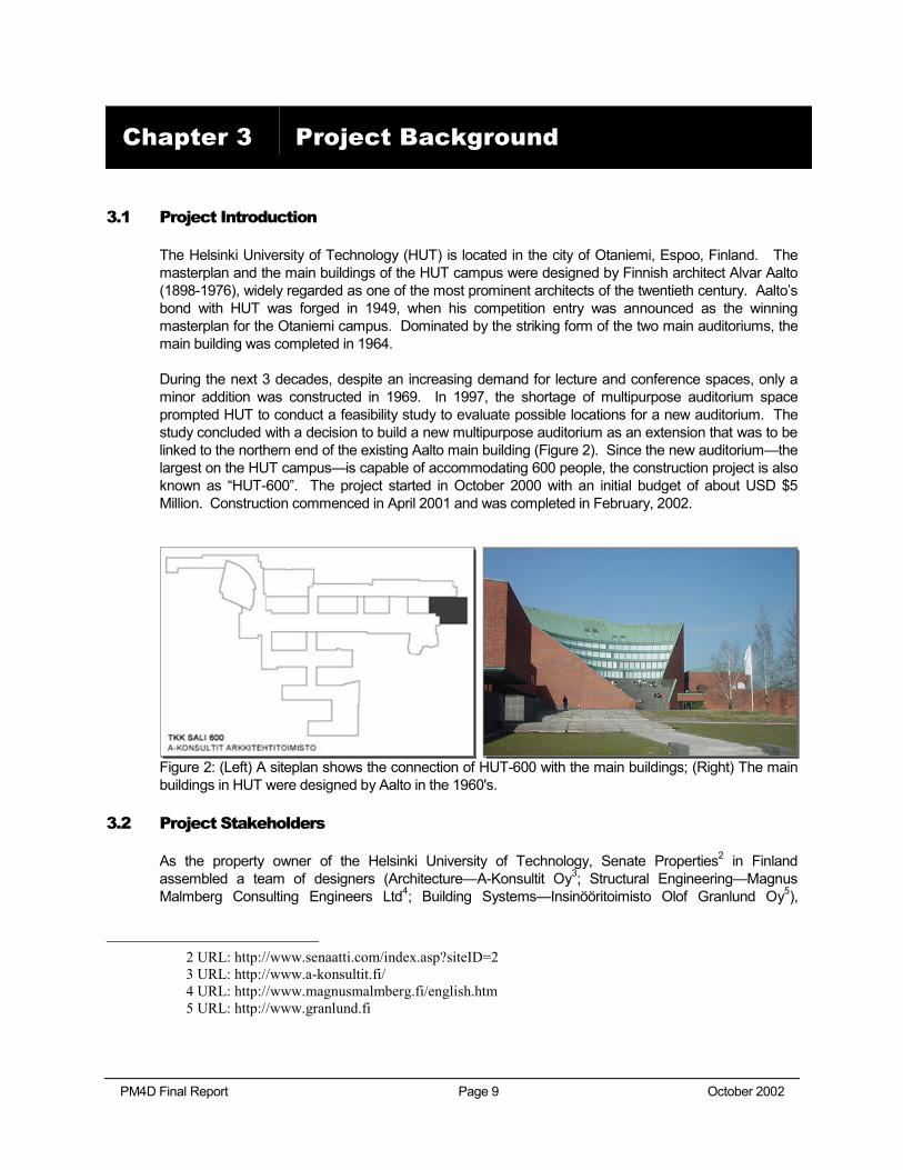
The existing HUT main building is among the most representative Aalto designs. Consequently, the style, appearance, and proportion of the new extension had to blend well with the campus masterplan and architecture designed by Aalto. For example, the new extension was limited to 4 meters in height to ensure that the views from the existing offices would not be blocked. The overall design as well as the meticulous selection of lighting fixtures or brick patterns had to receive approval by the Alvar Aalto Foundation. In addition to architectural constraints, the adjacent parking lot and the ongoing activities around the construction site formed a tight site boundary and posed construction challenges to the building of HUT-600. Furthermore, there was a tight design and construction schedule challenging both the construction project and the research activities.
Figure 3: Timeline showing the major project phases and the concurrency among design development, construction documentation, and construction.
3.4 Conventional Practices versus PM4D Approach
The PM4D Approach leverages state-of-the art analytical and visualization tools that are commercially available to support life-cycle analyses and improvements during early project phases. The approach aims at attaining higher accuracy and improved efficiency in facility design and construction, while also focusing on life-cycle factors. In the HUT-600 project, the PM4D Approach included the following array of tools, standards, and technologies:
6 URL: http://www.yit.fi 7 URL: http://cife.stanford.edu 8 URL: http://www.tekes.fi/eng/default.asp 9 URL: http://www.tekes.fi/english/vera
PM4D Final Report Page 11 October 2002
• Object-oriented product modeling software (in architectural design, mechanical design, construction planning, scheduling, and cost estimating)
• Industry Foundation Classes (IFC) interoperability standards and conversion middleware
• 4D CAD
• Thermal comfort and energy simulation software
• Computational fluid dynamic analysis software
• Lighting simulation software
• Design model checker
• Environmental impact assessment software
• Life-cycle cost comparison software
• Virtual Reality
• Project databank (extranet service)
The next chapter provides a more detailed explanation of the PM4D Approach and the related processes that took place in the HUT-600 auditorium project.
PM4D Final Report Page 12 October 2002
This Chapter explains the motivations for the HUT-600 project team to develop the PM4D Approach. The PM4D Processes subsection describes the procedures, information flows, and software used during the design and construction of the HUT-600 project.
4.1 PM4D Approach
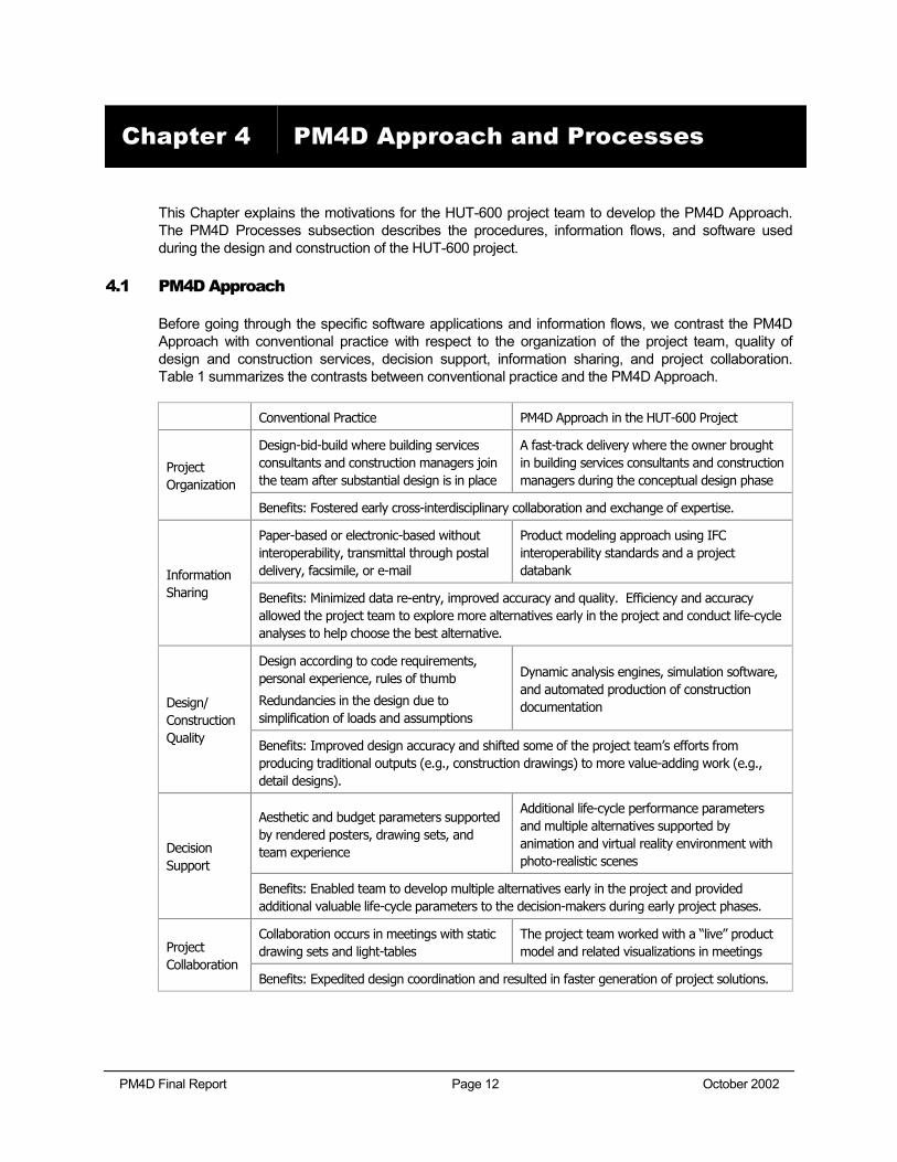
Before going through the specific software applications and information flows, we contrast the PM4D Approach with conventional practice with respect to the organization of the project team, quality of design and construction services, decision support, information sharing, and project collaboration. Table 1 summarizes the contrasts between conventional practice and the PM4D Approach.
Conventional Practice PM4D Approach in the HUT-600 Project
Design-bid-build where building services consultants and construction managers join the team after substantial design is in place
A fast-track delivery where the owner brought in building services consultants and construction managers during the conceptual design phase
Project Organization
Benefits: Fostered early cross-interdisciplinary collaboration and exchange of expertise.
Paper-based or electronic-based without interoperability, transmittal through postal delivery, facsimile, or e-mail
Product modeling approach using IFC interoperability standards and a project databank Information
Sharing Benefits: Minimized data re-entry, improved accuracy and quality. Efficiency and accuracy allowed the project team to explore more alternatives early in the project and conduct life-cycle analyses to help choose the best alternative.
Design according to code requirements, personal experience, rules of thumb
Redundancies in the design due to simplification of loads and assumptions
Dynamic analysis engines, simulation software, and automated production of construction documentation Design/
Construction Quality Benefits: Improved design accuracy and shifted some of the project team’s efforts from
producing traditional outputs (e.g., construction drawings) to more value-adding work (e.g., detail designs).
Aesthetic and budget parameters supported by rendered posters, drawing sets, and team experience
Additional life-cycle performance parameters and multiple alternatives supported by animation and virtual reality environment with photo-realistic scenes
Decision Support
Benefits: Enabled team to develop multiple alternatives early in the project and provided additional valuable life-cycle parameters to the decision-makers during early project phases.
Collaboration occurs in meetings with static drawing sets and light-tables
The project team worked with a “live” product model and related visualizations in meetings Project
Collaboration Benefits: Expedited design coordination and resulted in faster generation of project solutions.
Chapter 4 PM4D Approach and Processes
PM4D Final Report Page 13 October 2002
4.1.1 Organization of Project Team
Recognizing the value of professional opinions from multiple disciplines early in a project, the HUT-600 owner Senate Properties selected and brought in building services consultants as well as construction managers during the conceptual planning phase. In the conventional design-bid-build project delivery method, consultants and construction managers do not have such opportunities to actively comment on design alternatives. Since it is much more effective to influence a project during its early planning phase, the HUT-600 project organization supported an early exchange of expert opinions among the design, consulting, and construction professionals. For instance, the architects, building systems consultants, and construction managers contributed their respective domain expertise to the generation of a reliable cost estimate during the conceptual design phase (Chapter 5.1). This approach better aligned the project design with the optimum life-cycle performance and reduced the risks of schedule delays or cost overruns due to constructability problems.
4.1.2 Quality of Design and Construction Services
The HUT-600 project team was committed to leveraging the product modeling approach in 3D with object intelligence. The architects, building systems designers, construction managers, and consultants constructed and maintained object-oriented product models with explicit knowledge of the building components, spatial definitions, material composition, and other parametric properties. Conventionally, the architecture/engineering/construction (AEC) industry relies on 2D drawings to represent the building design. Unlike object-oriented models, two-dimensional lines and symbols do not support automatic analyses or simulations studies. The setback of conventional practice is that professionals often have to redefine and reinterpret project situations before they can conduct in-depth analytical studies. In response to time constraints, the project team often abstracts the problem settings, approximates the extreme design considerations, or applies minimum code requirements. In contrast, in the HUT-600 project, the PM4D Approach utilized the object intelligence embodied in a product model to improve the accuracy and quality of conventional design and construction services.
Example:
To set a design target for mechanical design in conventional practice, mechanical consultants have to take off spatial dimensions manually from a set of architectural drawings. They have to mentally relate the plan, elevation, section, and detail drawing sheets to search for openings, materials, fenestration assemblies, and construction details in the target space. From external references or code regulations, the designers need to obtain design guidelines to approximate the site climate data from extreme design days. The designers either have to spend long hours to reconstruct the space and synthesize relevant information from different sources, or simplify the design conditions and have to overdesign, potentially jeopardizing the quality of the design. In contrast, the HUT-600 mechanical consultants employed an object-oriented simulation tool that directly recognized geometric, spatial, and compositional information from the architectural product model. Rather than taking extreme design conditions, the simulation tool automatically predicted the indoor cooling and heating loads based on a database of past climate data at an hourly increment over a 12-month period. The product model enabled the mechanical designers to create a precise design for the specific conditions of the project in a short time.
4.1.3 Decision Support
The PM4D Approach included the use of various visualization tools to review the spatial aspects of the design with virtual walk-throughs, compare lighting schemes in photo-realistic renderings, and comprehend the construction sequence with 4D animations during the decision-making processes.
PM4D Final Report Page 14 October 2002
The AEC industry has been using artist renderings, posters, physical models, and in recent years, 3D models (without object intelligence) for presentations to their clients. The limitations of these traditional means are that they are frozen in time and labor-intensive to produce.
The PM4D Approach enabled the team to focus on the facility’s total life span. In the HUT-600 project, the designers and contractors conducted life-cycle analyses that were beyond the scope of conventional AEC practice. They provided valuable recommendations and additional life-cycle performance data to support their clients’ decision-making processes.
Example:
A colorful perspective rendering or a physical model requires an artist or a modeler to spend a considerable amount of time on a particular design idea. Hence, even though there may be additional design alternatives as the project is progressing, these renderings and physical models only represent a design concept frozen in time. Any modifications require a substantial amount of time and resource reinvestments to generate the new perspective or model. In the HUT-600 project, virtual models played a more important role than conventional decision support means. A goal of the PM4D Approach was to support frequent and rapid generation of multiple project alternatives utilizing existing information from product models, construction schedules, etc.
4.1.4 Information Sharing
The HUT-600 project team tested the Industry Foundation Classes (IFC) interoperability standard and a project extranet for information sharing. To further exploit the potential benefits of the product modeling approach, the team adopted IFC’s—an evolving international information exchange standard that allows project participants to work across different application packages with data continuity. The International Alliance for Interoperability10 (IAI) defines interoperability as “an environment in which computer programs can share and exchange data automatically, regardless of the type of software or of where the data may be residing” (IAI 1995). Conventional information sharing methods require practitioners to re-enter data as their respective software applications do not share the same data format. With traditional means of information sharing, such as paper-based documents or non-interoperable electronic-based files, project teams lose crucial design and construction information and knowledge as their projects evolve.
Hence, the architects, engineers, contractors, and the researchers on the HUT-600 project tested the extent to which the exchange of IFC-based project data could take place among commercially available applications (Figure 3). They also wanted to find out how IFC-compliant applications affect project efficiency and quality of data.
10 URL: http://www.iai-international.org/iai_international/
PM4D Final Report Page 15 October 2002
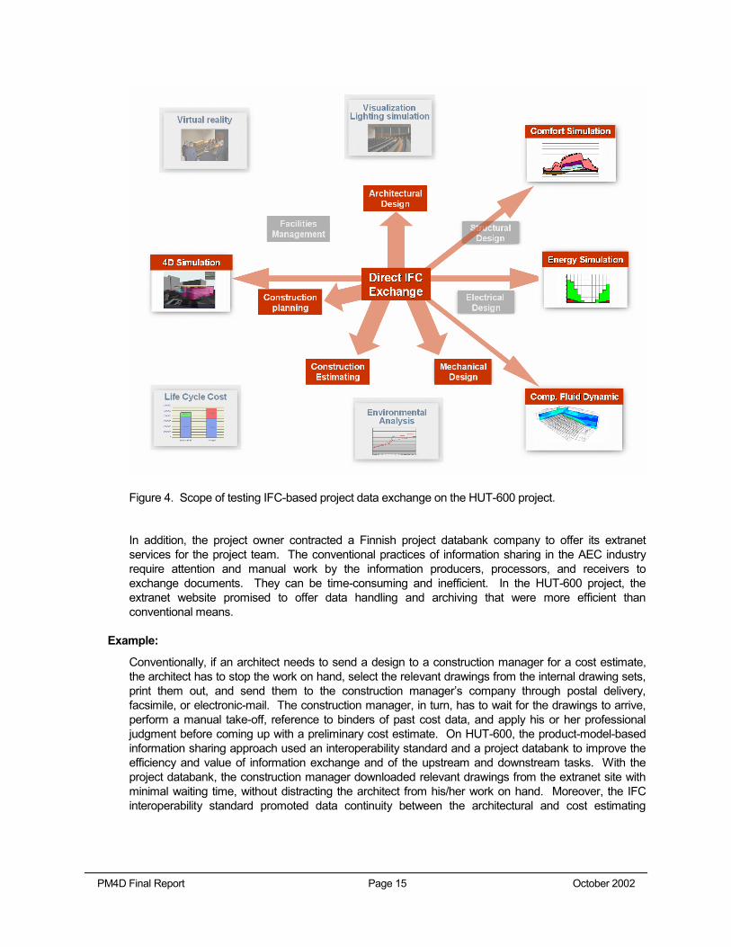
Figure 4. Scope of testing IFC-based project data exchange on the HUT-600 project.
In addition, the project owner contracted a Finnish project databank company to offer its extranet services for the project team. The conventional practices of information sharing in the AEC industry require attention and manual work by the information producers, processors, and receivers to exchange documents. They can be time-consuming and inefficient. In the HUT-600 project, the extranet website promised to offer data handling and archiving that were more efficient than conventional means.
Example:
Conventionally, if an architect needs to send a design to a construction manager for a cost estimate, the architect has to stop the work on hand, select the relevant drawings from the internal drawing sets, print them out, and send them to the construction manager’s company through postal delivery, facsimile, or electronic-mail. The construction manager, in turn, has to wait for the drawings to arrive, perform a manual take-off, reference to binders of past cost data, and apply his or her professional judgment before coming up with a preliminary cost estimate. On HUT-600, the product-model-based information sharing approach used an interoperability standard and a project databank to improve the efficiency and value of information exchange and of the upstream and downstream tasks. With the project databank, the construction manager downloaded relevant drawings from the extranet site with minimal waiting time, without distracting the architect from his/her work on hand. Moreover, the IFC interoperability standard promoted data continuity between the architectural and cost estimating
PM4D Final Report Page 16 October 2002
software applications. Hence, the construction manager could rely on the computer application and its database to expedite the quantity take-off and match cost data with design data, while spending more time in more valuable tasks such as applying his/her construction and pricing expertise.
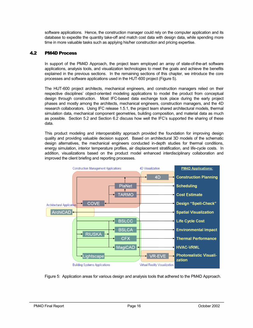
4.2 PM4D Process
In support of the PM4D Approach, the project team employed an array of state-of-the-art software applications, analysis tools, and visualization technologies to meet the goals and achieve the benefits explained in the previous sections. In the remaining sections of this chapter, we introduce the core processes and software applications used in the HUT-600 project (Figure 5).
The HUT-600 project architects, mechanical engineers, and construction managers relied on their respective disciplines’ object-oriented modeling applications to model the product from conceptual design through construction. Most IFC-based data exchange took place during the early project phases and mostly among the architects, mechanical engineers, construction managers, and the 4D research collaborators. Using IFC release 1.5.1, the project team shared architectural models, thermal simulation data, mechanical component geometries, building composition, and material data as much as possible. Section 5.2 and Section 6.2 discuss how well the IFC’s supported the sharing of these data.
This product modeling and interoperability approach provided the foundation for improving design quality and providing valuable decision support. Based on architectural 3D models of the schematic design alternatives, the mechanical engineers conducted in-depth studies for thermal conditions, energy simulation, interior temperature profiles, air displacement stratification, and life-cycle costs. In addition, visualizations based on the product model enhanced interdisciplinary collaboration and improved the client briefing and reporting processes.
Figure 5: Application areas for various design and analysis tools that adhered to the PM4D Approach.
PM4D Final Report Page 17 October 2002
4.2.1 Product Model Exchange
With ArchiCAD from Graphisoft11, the architects created a 3D model in the conceptual planning phase, and continually maintained and updated the product model through the construction documentation phase. The architects assigned accurate properties (e.g., materials, construction assembly, etc.) to the virtual building components, providing the starting point for other project team members to follow the PM4D Approach with their respective software applications.
The mechanical engineers were ready to design the Heating, Ventilating, and Air-Conditioning (HVAC) system once they received the target design values from the thermal simulation tool (see 4.2.2) as well as the spatial configurations and geometries from ArchiCAD. The HUT-600 mechanical engineers employed Progman Oy’s MagiCAD12 to conduct 3D modeling and optimization of the cooling and heating systems.
The construction managers used YIT Corporation’s Cost and Value Engineering13 (COVE) software, powered by Finnish software developer SOLIBRI14. COVE serves as a plug-in to ArchiCAD and thus is also object-oriented. In support of the PM4D Approach, COVE extracted object information from the product model and mapped the building components against YIT’s proprietary cost estimating software TARMO and scheduling software PLANET. Without data re-entry, the intelligence of the object-oriented product model allowed the construction managers to quickly generate a baseline cost estimate and a construction schedule.
4.2.2 Thermal Design and Analyses
Importing the product model from an ArchiCAD export, the building system consultants used RIUSKA15, developed by Olof Granlund Oy, to run thermal simulations to estimate the heat gain and heat loss of the building in response to the climate, architectural configuration, and the anticipated operation by the occupants. In addition to RIUSKA, the mechanical system consultants also used CFX16, developed by AEA Technology, to conduct computational fluid dynamics (CFD) analyses. Given a set of boundary conditions, CFD iteratively solves partial differential equations to yield numerical solutions. In line with the PM4D Approach to improve design services and to provide better decision supports, the consultants utilized CFD to investigate the profiles of temperature and air velocity stratification within the critical auditorium space.
4.2.3 Life-Cycle Analyses
Since the owner was looking for better facility performance, the building system consultants of the HUT-600 project conducted an environmental impact assessment to evaluate the environmental impact of the building materials and energy for this facility. With Olof Granlund Oy’s BSLCA software, the consultants quantified the amount of pollution emission, global warming, acidification, etc. in support for material and system selection. On the other hand, the consultants also employed Granlund’s BSLCC17 to estimate the operation and maintenance costs of project alternatives all through the facility’s expected life-span.
11 URL: http://www.graphisoft.com 12 URL: http://www.progman.fi/english/e_index.htm 13 URL: http://www.yit.fi/yit/yitdesc.nsf/APPHTM/GroupEnglishRD?OpenDocument 14 URL: http://www.solibri.com/index.html 15 URL: http://www.eren.doe.gov/buildings/tools_directory/software/riuska.htm 16 URL: http://www.software.aeat.com/cfx/ 17 URL: http://www.granlund.fi/English/tyo-retu.htm
PM4D Final Report Page 18 October 2002
4.2.4 Exchange of Project Data with IFC
To leverage project data generated by other disciplines, participants, and software and to minimize re-entry of data and improve the efficiency of information sharing, the project team used the Industry Foundation Classes (IFC) interoperability standard as much as possible to exchange project data.
Since 1995, the International Alliance of Interoperability (IAI) has been defining and promoting the use of the Industry Foundation Classes (IFC) interoperability standard. It defines interoperability in the building industry as “an environment in which computer programs can share and exchange data automatically (without translation or human intervention), regardless of the type of software or of where the data may be residing” (IAI 1995). The alliance aims at utilizing the IFC, an interoperable standard, to define a single object-oriented data model to allow different disciplines to accurately share technical information with IFC-compliant tools. The IAI strives to provide a universal standard for sharing cross-disciplinary data among the fields of building design, construction, and operation. This allows project participants to share project information across different application packages and to build upon existing data, while eliminating the inefficiencies and inconsistencies associated with conventional practices of data re-entry. Hence, if each software application followed this international standard and developed appropriate data mappings and conversions, the industry could better enjoy the benefits such as two-way conversion of project information, transfer of object intelligence, etc. between software applications.
The HUT-600 project is one of the first live industrial pilot applications of the IFC. With the IFC-compliant design software ArchiCAD, the HUT-600 architectural designers generated IFC files that contained a three-dimensional building geometric model, space identity, and building material information. The IFC files the architects exported were read by the RIUSKA tool, through a middleware tool—BSPro18—to conduct thermal simulations. The ArchiCAD files were also read by COVE to generate cost estimates and schedules; BSLCA, via BSPro, to assess environmental impacts; and the research collaborator’s 4D software CPT 4D from Common Point Technologies19 via BSPro as the middleware tool (refer to 4.2.6).
4.2.5 Lighting Design
The lighting design played a crucial role in the electrical design on the HUT-600 project. The lighting designers at Olof Granlund Oy used the company’s proprietary lighting product database—VIVA to select and compare lighting products. By early 2002, the VIVA database contained about 6,000 lighting products, of which almost 1,000 were readily available in 3D format. Once the designers had checked the light distribution curve, rating, installation specifications, and energy requirements for the lighting products, they imported the 3D lighting objects into LIGHTSCAPE20, developed by Autodesk. Merging the lighting fixtures with the architectural product model, LIGHTSCAPE generated photorealistic model scenes using a ray-tracing approach. These model scenes provided designers with a thorough understanding of the lighting effects and thus allowed them to refine their design and improve the auditorium’s quality of light. At the same time, they became crucial visualization tools that conveyed the design intent to the end-users and the owners for feedback.
18 URL: http://www.bspro.net 19 URL: http://www.commonpointinc.com 20 URL: http://usa.autodesk.com/adsk/section/0,,775058-123112,00.html
PM4D Final Report Page 19 October 2002
4.2.6 4D Visualization
The contractor and CIFE generated 4D models that linked 3D geometries with the construction schedule. The contractors exported the schedule from COVE to their 4D application. On the other hand, CIFE researchers used the 4D tool21 developed by Walt Disney Imagineering and CIFE’s 4D CAD research group22 at Stanford University. Both 4D models displayed an animated sequencing of the virtual construction according to the architect’s design and the contractor’s schedule. They were project collaboration and decision support tools for the owners, end-users, design team, construction team, and the consultants to visualize, comprehend, and discuss the construction process.
4.2.7 Virtual Reality Visualization
In the Computer Science Department at the Helsinki University of Technology, there is an Experimental Virtual Environment23 (EVE) where a room of 3 rear-projectors, 1 top-projector, and several high-end computers assemble a virtual reality space. The HUT-600 project team collaborated with the researchers at EVE and virtually constructed a 3D immersive Auditorium-600 based on the ArchiCAD product model and the LIGHTSCAPE ray-traced scenes. The EVE contributed to the PM4D Approach and the decision support through improving the client briefing environment (See Section 5.4.2).
21 URL: http://www.commonpointinc.com 22 URL: http://www.stanford.edu/group/4D 23 URL: http://www.tml.hut.fi/Research/HUTVE/
PM4D Final Report Page 20 October 2002
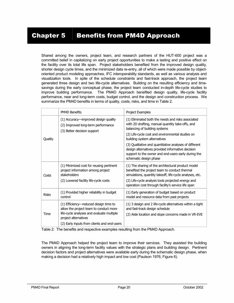
Shared among the owners, project team, and research partners of the HUT-600 project was a committed belief in capitalizing on early project opportunities to make a lasting and positive effect on the facility over its total life span. Project stakeholders benefited from the improved design quality, shorter design cycle times, and the minimized data re-entry, all of which were made possible by object-oriented product modeling approaches, IFC interoperability standards, as well as various analysis and visualization tools. In spite of the schedule constraints and fast-track approach, the project team generated three design and two life-cycle alternatives. Building on the resulting efficiency and time-savings during the early conceptual phase, the project team conducted in-depth life-cycle studies to improve building performance. The PM4D Approach benefited design quality, life-cycle facility performance, near and long-term costs, budget control, and the design and construction process. We summarize the PM4D benefits in terms of quality, costs, risks, and time in Table 2.
PM4D Benefits Project Examples
Quality
(1) Accuracy—improved design quality
(2) Improved long-term performance
(3) Better decision support
(1) Eliminated both the needs and risks associated with 2D drafting, manual quantity take-offs, and balancing of building systems
(2) Life-cycle cost and environmental studies on building system alternatives
(3) Qualitative and quantitative analyses of different design alternatives provided informative decision support to the owner and end-users early during the schematic design phase
Costs
(1) Minimized cost for reusing pertinent project information among project stakeholders
(2) Lowered facility life-cycle costs
(1) The sharing of the architectural product model benefited the project team to conduct thermal simulations, quantity takeoff, life-cycle analyses, etc.
(2) Life-cycle analysis tools projected energy and operation cost through facility’s service life span
Risks (1) Provided higher reliability in budget control
(1) Early generation of budget based on product model and resource data from past projects
Time
(1) Efficiency—reduced design time to allow the project team to conduct more life-cycle analyses and evaluate multiple project alternatives
(2) Early inputs from clients and end-users
(1) 3 design and 2 life-cycle alternatives within a tight and fast-track design schedule
(2) Aisle location and slope concerns made in VR-EVE
Table 2: The benefits and respective examples resulting from the PM4D Approach.
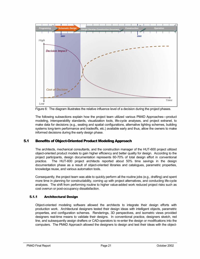
The PM4D Approach helped the project team to improve their services. They assisted the building owners in aligning the long-term facility values with the strategic plans and building design. Pertinent decision factors and project alternatives were available early during the schematic design phase, when making a decision had a relatively high impact and low cost (Paulson 1976, Figure 6).
Chapter 5 Benefits from PM4D Approach
PM4D Final Report Page 21 October 2002
Figure 6: The diagram illustrates the relative influence level of a decision during the project phases.
The following subsections explain how the project team utilized various PM4D Approaches—product modeling, interoperability standards, visualization tools, life-cycle analyses, and project extranet, to make data for decisions (e.g., seating and spatial configurations, alternative lighting schemes, building systems long-term performance and tradeoffs, etc.) available early and thus, allow the owners to make informed decisions during the early design phase.
5.1 Benefits of Object-Oriented Product Modeling Approach
The architects, mechanical consultants, and the construction manager of the HUT-600 project utilized object-oriented product models to gain higher efficiency and better quality for design. According to the project participants, design documentation represents 60-70% of total design effort in conventional practice. The HUT-600 project architects reported about 50% time savings in the design documentation phase as a result of object-oriented libraries and catalogues, parametric properties, knowledge reuse, and various automation tools.
Consequently, the project team was able to quickly perform all the routine jobs (e.g., drafting) and spent more time in planning for constructability, coming up with project alternatives, and conducting life-cycle analyses. The shift from performing routine to higher value-added work reduced project risks such as cost overrun or post-occupancy dissatisfaction.
5.1.1 Architectural Design
Object-oriented modeling software allowed the architects to integrate their design efforts with production work. Architectural designers tested their design ideas with intelligent objects, parametric properties, and configuration schemes. Renderings, 3D perspectives, and isometric views provided designers real-time means to validate their designs. In conventional practice, designers sketch, red line, and subsequently assign drafters or CAD-operators to re-enter the design or modifications into the computers. The PM4D Approach allowed the designers to design and test their ideas with the object-
PM4D Final Report Page 22 October 2002
oriented application. They eliminated the hassle and redundancy of “red-marking” that exist with a traditional drafting tool. The HUT-600 architects constantly worked with a 3D model that reflected the decisions made up to that point, from which they could quickly generate production documents such as plans, sections, and elevations. Meanwhile, the approaches also enabled the designers to develop automated drawing production scripts, which avoided the complication of setting up a hierarchy to organize all the drawing file references.
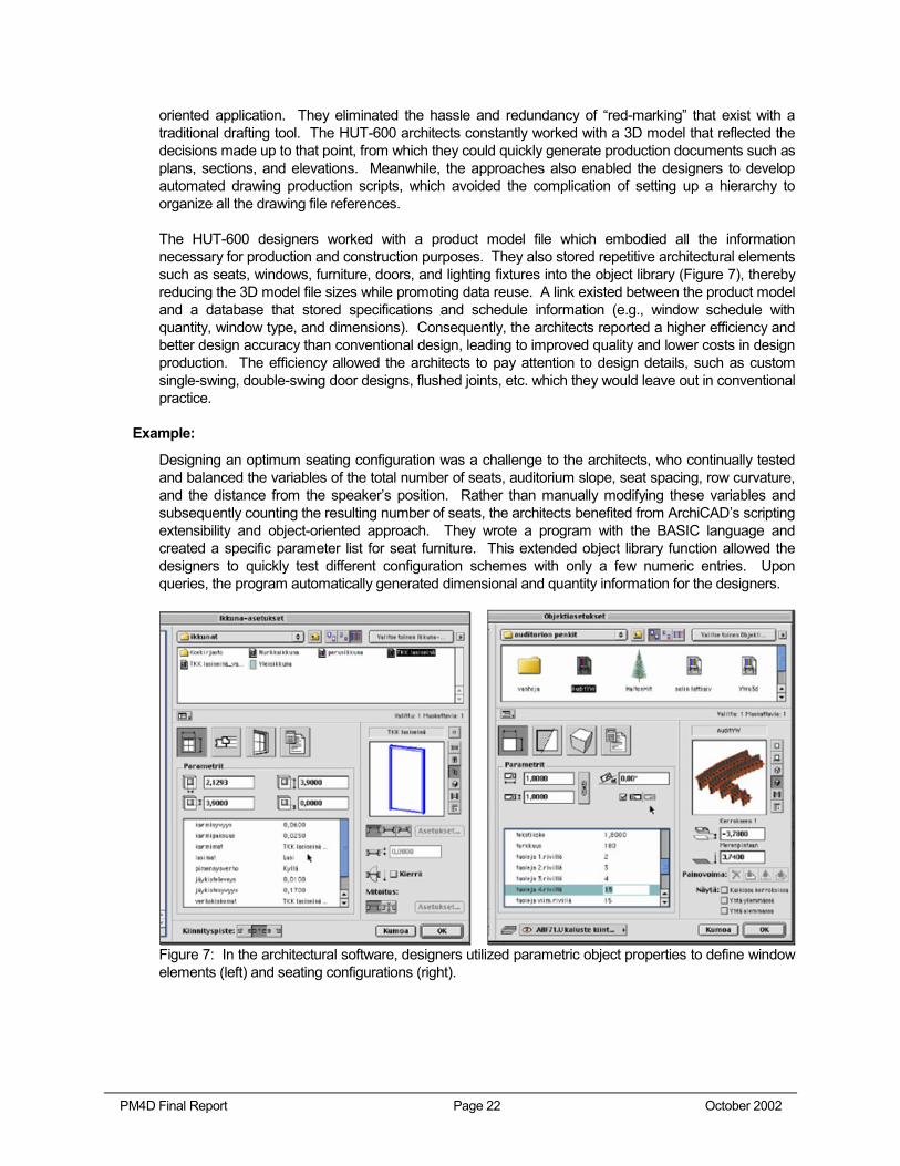
The HUT-600 designers worked with a product model file which embodied all the information necessary for production and construction purposes. They also stored repetitive architectural elements such as seats, windows, furniture, doors, and lighting fixtures into the object library (Figure 7), thereby reducing the 3D model file sizes while promoting data reuse. A link existed between the product model and a database that stored specifications and schedule information (e.g., window schedule with quantity, window type, and dimensions). Consequently, the architects reported a higher efficiency and better design accuracy than conventional design, leading to improved quality and lower costs in design production. The efficiency allowed the architects to pay attention to design details, such as custom single-swing, double-swing door designs, flushed joints, etc. which they would leave out in conventional practice.
Example:
Designing an optimum seating configuration was a challenge to the architects, who continually tested and balanced the variables of the total number of seats, auditorium slope, seat spacing, row curvature, and the distance from the speaker’s position. Rather than manually modifying these variables and subsequently counting the resulting number of seats, the architects benefited from ArchiCAD’s scripting extensibility and object-oriented approach. They wrote a program with the BASIC language and created a specific parameter list for seat furniture. This extended object library function allowed the designers to quickly test different configuration schemes with only a few numeric entries. Upon queries, the program automatically generated dimensional and quantity information for the designers.
Figure 7: In the architectural software, designers utilized parametric object properties to define window elements (left) and seating configurations (right).
PM4D Final Report Page 23 October 2002
5.1.2 Mechanical Design
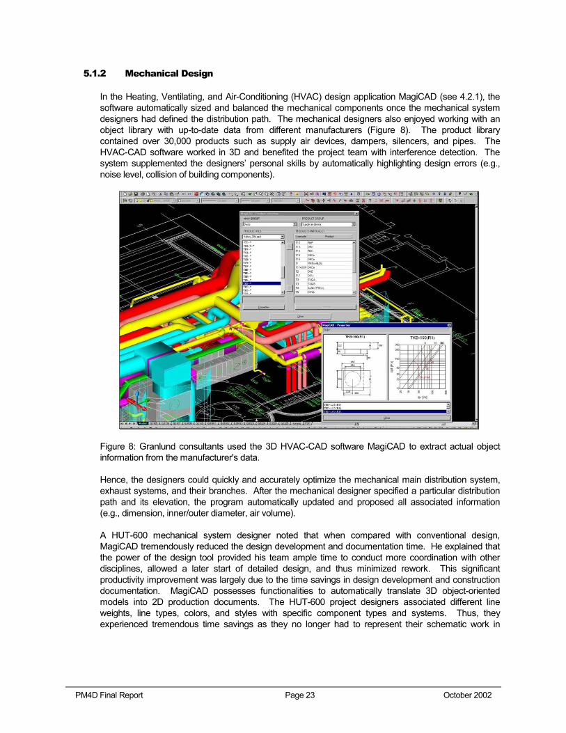
In the Heating, Ventilating, and Air-Conditioning (HVAC) design application MagiCAD (see 4.2.1), the software automatically sized and balanced the mechanical components once the mechanical system designers had defined the distribution path. The mechanical designers also enjoyed working with an object library with up-to-date data from different manufacturers (Figure 8). The product library contained over 30,000 products such as supply air devices, dampers, silencers, and pipes. The HVAC-CAD software worked in 3D and benefited the project team with interference detection. The system supplemented the designers’ personal skills by automatically highlighting design errors (e.g., noise level, collision of building components).
Figure 8: Granlund consultants used the 3D HVAC-CAD software MagiCAD to extract actual object information from the manufacturer's data.
Hence, the designers could quickly and accurately optimize the mechanical main distribution system, exhaust systems, and their branches. After the mechanical designer specified a particular distribution path and its elevation, the program automatically updated and proposed all associated information (e.g., dimension, inner/outer diameter, air volume).
A HUT-600 mechanical system designer noted that when compared with conventional design, MagiCAD tremendously reduced the design development and documentation time. He explained that the power of the design tool provided his team ample time to conduct more coordination with other disciplines, allowed a later start of detailed design, and thus minimized rework. This significant productivity improvement was largely due to the time savings in design development and construction documentation. MagiCAD possesses functionalities to automatically translate 3D object-oriented models into 2D production documents. The HUT-600 project designers associated different line weights, line types, colors, and styles with specific component types and systems. Thus, they experienced tremendous time savings as they no longer had to represent their schematic work in
PM4D Final Report Page 24 October 2002
production styles all over again. Furthermore, MagiCAD generated bills of materials for the general contractors and contributed to their quick generation of cost estimates.
Example:
In conventional design, it is cumbersome to calculate the noise levels from a mechanical distribution system as the designers are continually balancing the system. In the HUT-600 project, the project team relied on the object-oriented software, which automatically calculated and displayed all the pressure drops and noise levels across the distribution system in less than a minute. Hence, rather than spending hours in searching for the exact noise level or the balance, the designers could fine tune their systems, evaluate other options, and look for specific products from the object library.
5.1.3 Construction Planning
In Section 4.2.1, we introduced YIT’s proprietary COVE system on top of SOLIBRI. The HUT-600 project followed a fast-track schedule. From conceptual design through construction, the construction management team played a crucial role in establishing and controlling the total project cost as well as validating the constructability of the architectural and building systems designs. COVE benefited the project team with its “Solibri Application Engine” that maps the ArchiCAD model database to the contractor’s internal cost estimating database and performs model checking.
Synthesizing the readily available bill of materials from the mechanical consultants and the three-dimensional geometry from the architects, COVE recognizes the components in the product model and automatically incorporates YIT’s past cost estimation, scheduling, and resource leveling data through TARMO. As a result, the construction managers could generate construction schedules and cost estimates more quickly and accurately than traditionally possible. The calibration with a pool of past construction project data made the cost estimate very reliable and allowed the owners to set up good budget control early on. Since the accuracy of the product model determined the reliability of costs and schedules, COVE’s ability to look for modeling mistakes (e.g., wrong layer assignments, collisions of building components) were valuable in validating the product model (Figure 9). Meanwhile, COVE also expedited the general contractor’s procurement and resource leveling tasks with automatic generation of bills of material and resource-loaded construction schedules.
PM4D Final Report Page 25 October 2002
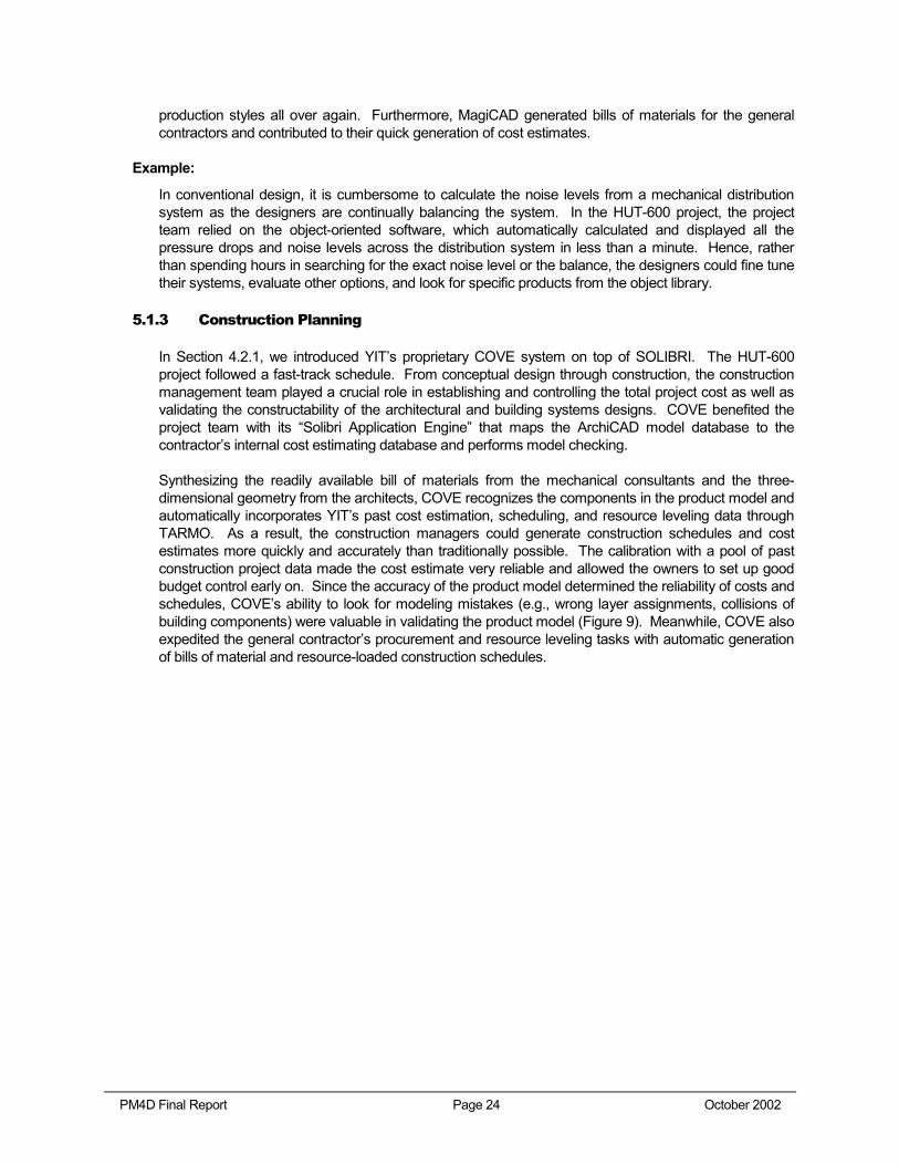
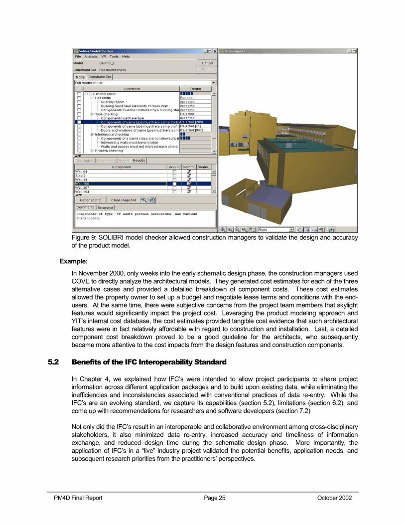
Figure 9: SOLIBRI model checker allowed construction managers to validate the design and accuracy of the product model.
Example:
In November 2000, only weeks into the early schematic design phase, the construction managers used COVE to directly analyze the architectural models. They generated cost estimates for each of the three alternative cases and provided a detailed breakdown of component costs. These cost estimates allowed the property owner to set up a budget and negotiate lease terms and conditions with the end-users. At the same time, there were subjective concerns from the project team members that skylight features would significantly impact the project cost. Leveraging the product modeling approach and YIT’s internal cost database, the cost estimates provided tangible cost evidence that such architectural features were in fact relatively affordable with regard to construction and installation. Last, a detailed component cost breakdown proved to be a good guideline for the architects, who subsequently became more attentive to the cost impacts from the design features and construction components.
5.2 Benefits of the IFC Interoperability Standard
In Chapter 4, we explained how IFC’s were intended to allow project participants to share project information across different application packages and to build upon existing data, while eliminating the inefficiencies and inconsistencies associated with conventional practices of data re-entry. While the IFC’s are an evolving standard, we capture its capabilities (section 5.2), limitations (section 6.2), and come up with recommendations for researchers and software developers (section 7.2)
Not only did the IFC’s result in an interoperable and collaborative environment among cross-disciplinary stakeholders, it also minimized data re-entry, increased accuracy and timeliness of information exchange, and reduced design time during the schematic design phase. More importantly, the application of IFC’s in a “live” industry project validated the potential benefits, application needs, and subsequent research priorities from the practitioners’ perspectives.
PM4D Final Report Page 26 October 2002
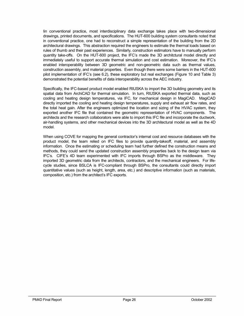
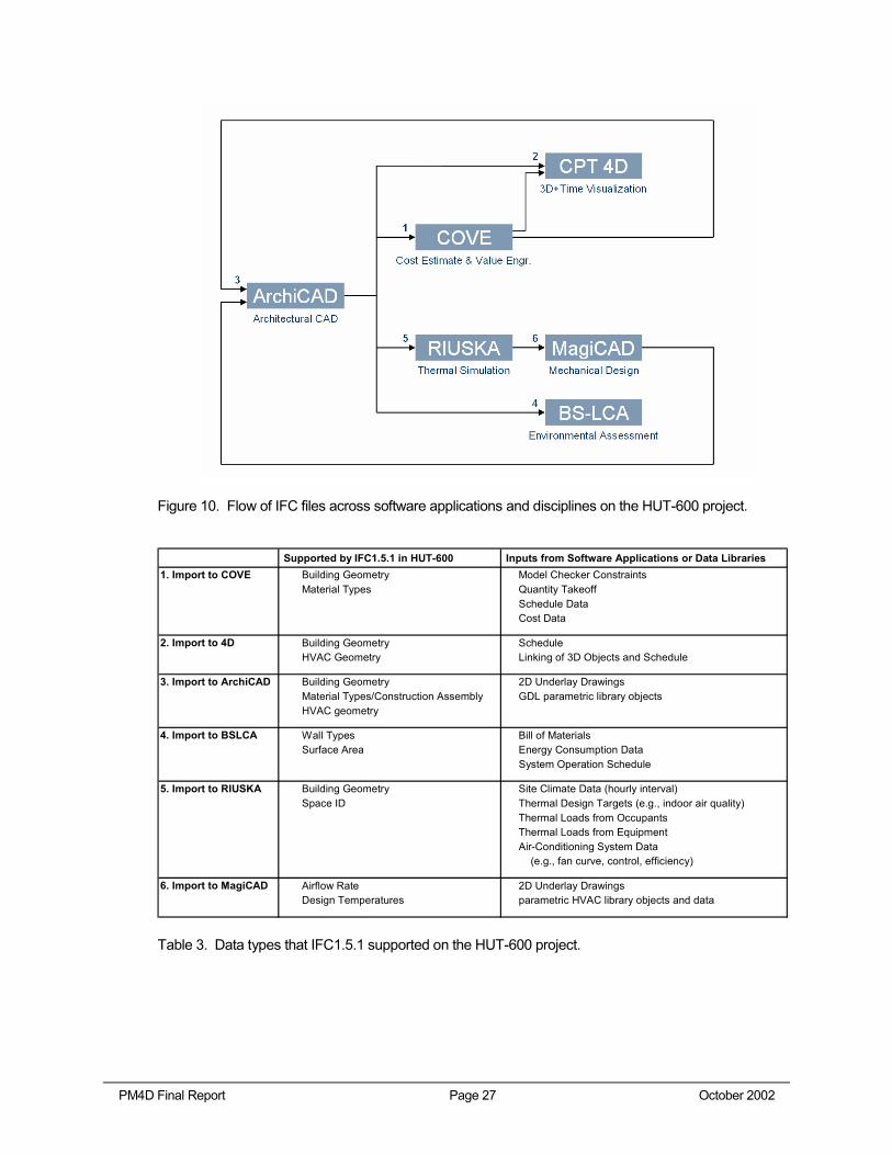
Iin conventional practice, most interdisciplinary data exchange takes place with two-dimensional drawings, printed documents, and specifications. The HUT-600 building system consultants noted that in conventional practice, one had to reconstruct a simple representation of the building from the 2D architectural drawings. This abstraction required the engineers to estimate the thermal loads based on rules of thumb and their past experiences. Similarly, construction estimators have to manually perform quantity take-offs. On the HUT-600 project, the IFC’s made the 3D architctural model directly and immediately useful to support accurate thermal simulation and cost estimation. Moreover, the IFC’s enabled interoperability between 3D geometric and non-geometric data such as thermal values, construction assembly, and material properties. Even though there were some barriers in the HUT-600 pilot implementation of IFC’s (see 6.2), these exploratory but real exchanges (Figure 10 and Table 3) demonstrated the potential benefits of data interoperability across the AEC industry.
Specifically, the IFC-based product model enabled RIUSKA to import the 3D building geometry and its spatial data from ArchiCAD for thermal simulation. In turn, RIUSKA exported thermal data, such as cooling and heating design temperatures, via IFC, for mechanical design in MagiCAD. MagiCAD directly imported the cooling and heating design temperatures, supply and exhaust air flow rates, and the total heat gain. After the engineers optimized the location and sizing of the HVAC system, they exported another IFC file that contained the geometric representation of HVAC components. The architects and the research collaborators were able to import this IFC file and incorporate the ductwork, air-handling systems, and other mechanical devices into the 3D architectural model as well as the 4D model.
When using COVE for mapping the general contractor’s internal cost and resource databases with the product model, the team relied on IFC files to provide quantity-takeoff, material, and assembly information. Once the estimating or scheduling team had further defined the construction means and methods, they could send the updated construction assembly properties back to the design team via IFC’s. CIFE’s 4D team experimented with IFC imports through BSPro as the middleware. They imported 3D geometric data from the architects, contractors, and the mechanical engineers. For life-cycle studies, since BSLCA is IFC-compliant through BSPro, the consultants could directly import quantitative values (such as height, length, area, etc.) and descriptive information (such as materials, composition, etc.) from the architect’s IFC exports.
PM4D Final Report Page 27 October 2002
Figure 10. Flow of IFC files across software applications and disciplines on the HUT-600 project.
Supported by IFC1.5.1 in HUT-600 Inputs from Software Applications or Data Libraries
1. Import to COVE Building Geometry Model Checker ConstraintsMaterial Types Quantity Takeoff
Schedule DataCost Data
2. Import to 4D Building Geometry ScheduleHVAC Geometry Linking of 3D Objects and Schedule
3. Import to ArchiCAD Building Geometry 2D Underlay DrawingsMaterial Types/Construction Assembly GDL parametric library objectsHVAC geometry
4. Import to BSLCA Wall Types Bill of MaterialsSurface Area Energy Consumption Data
System Operation Schedule
5. Import to RIUSKA Building Geometry Site Climate Data (hourly interval)Space ID Thermal Design Targets (e.g., indoor air quality)
Thermal Loads from OccupantsThermal Loads from EquipmentAir-Conditioning System Data (e.g., fan curve, control, efficiency)
6. Import to MagiCAD Airflow Rate 2D Underlay DrawingsDesign Temperatures parametric HVAC library objects and data
Table 3. Data types that IFC1.5.1 supported on the HUT-600 project.
PM4D Final Report Page 28 October 2002
5.3 Benefits of Thermal Simulations
The thermal simulation tool RIUSKA and computational fluid dynamics software CFX supplemented each other to provide a series of in-depth analyses of the auditorium space. With heat emission from 600 users and more than 200 light fixtures, the auditorium space relied on product-model based analysis tools to quickly and precisely determine its appropriate design targets (e.g., cooling and heating temperatures, air flow rates, etc.). In the two following subsections, we focus on the design of the air-conditioning system to highlight how the PM4D Approach and Processes benefited the design of the mechanical system.
5.3.1 Comfort and Energy Simulation
The broader and more comprehensive approach in the HUT-600 project to comfort and energy simulation was beneficial for building systems design and selection of system components. Importing the architectural product model based on IFC1.5.1, RIUSKA took into account the dynamic behavior of thermal masses in response to the changing exterior temperatures in hourly increments over a 12-month period. Such dynamic behavior is usually approximated or omitted in conventional analysis. The project team was able to combine different spaces and building systems to test different insulation options across the three architectural alternatives. By using electronic library of design and annual climate data, the HUT-600 mechanical designers designed and dimensioned the mechanical system according to specific indoor air quality targets. RIUSKA allowed the designers to specify an indoor air temperature target (25 degree Celsius in HUT-600), with which the program analyzed the thermal loads from the occupancy, the occupants’ schedule, equipment loads, and the exterior temperature conditions against the different insulation, window transmittance, and louver systems.
Subsequently, the team utilized RIUSKA to simulate the effect of two air-conditioning system alternatives: mixed ventilation versus displacement ventilation systems. They determined that a mixed system would yield a supply air temperature at 17 degree Celsius, versus 19 degree Celsius by the displacement system. The flow rates of both systems were identical. Since RIUSKA only calculates the average temperature in a thermal space, the designers needed to analyze the temperature stratification in greater depth using Computation Fluid Dynamics (CFD). In the following section, we explain how CFD was used together with RIUSKA simulations to provide additional analytical results that pertained to the indoor conditions of the auditorium.
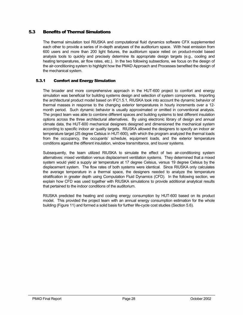
RIUSKA predicted the heating and cooling energy consumption by HUT-600 based on its product model. This provided the project team with an annual energy consumption estimation for the whole building (Figure 11) and formed a solid basis for further life-cycle cost studies (Section 5.6).
PM4D Final Report Page 29 October 2002
Figure 11. RIUSKA projected the annual heating and cooling energy consumption for HUT-600.
5.3.2 Computational Fluid Dynamics
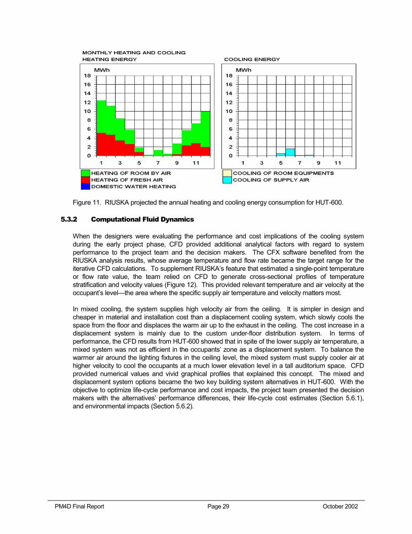
When the designers were evaluating the performance and cost implications of the cooling system during the early project phase, CFD provided additional analytical factors with regard to system performance to the project team and the decision makers. The CFX software benefited from the RIUSKA analysis results, whose average temperature and flow rate became the target range for the iterative CFD calculations. To supplement RIUSKA’s feature that estimated a single-point temperature or flow rate value, the team relied on CFD to generate cross-sectional profiles of temperature stratification and velocity values (Figure 12). This provided relevant temperature and air velocity at the occupant’s level—the area where the specific supply air temperature and velocity matters most.
In mixed cooling, the system supplies high velocity air from the ceiling. It is simpler in design and cheaper in material and installation cost than a displacement cooling system, which slowly cools the space from the floor and displaces the warm air up to the exhaust in the ceiling. The cost increase in a displacement system is mainly due to the custom under-floor distribution system. In terms of performance, the CFD results from HUT-600 showed that in spite of the lower supply air temperature, a mixed system was not as efficient in the occupants’ zone as a displacement system. To balance the warmer air around the lighting fixtures in the ceiling level, the mixed system must supply cooler air at higher velocity to cool the occupants at a much lower elevation level in a tall auditorium space. CFD provided numerical values and vivid graphical profiles that explained this concept. The mixed and displacement system options became the two key building system alternatives in HUT-600. With the objective to optimize life-cycle performance and cost impacts, the project team presented the decision makers with the alternatives’ performance differences, their life-cycle cost estimates (Section 5.6.1), and environmental impacts (Section 5.6.2).
PM4D Final Report Page 30 October 2002
Figure 12. CFX provided CFD cross-sectional profiles of air velocity in the displacement cooling scenario (left) as well as the mixed cooling scenario (right).
5.4 Benefits of Visualizations
The project team aimed at understanding the expected spatial experiences of the auditorium users early in the project and meeting the expectations of their clients. They used visualization tools, such as a virtual reality-Experimental Virtual Environment (EVE) and 4D CAD, to foster communication among the end-users, owners and the project team. Once the clients comprehended the design through visualization tools, they could ask more what-if questions, get cost and performance feedback, and provide necessary inputs to the project team much earlier than typically possible. As a result, the project team could capture more valuable inputs during the schematic design phases and subsequently translate the client’s intent into lasting values.
5.4.1 Lighting Visualization
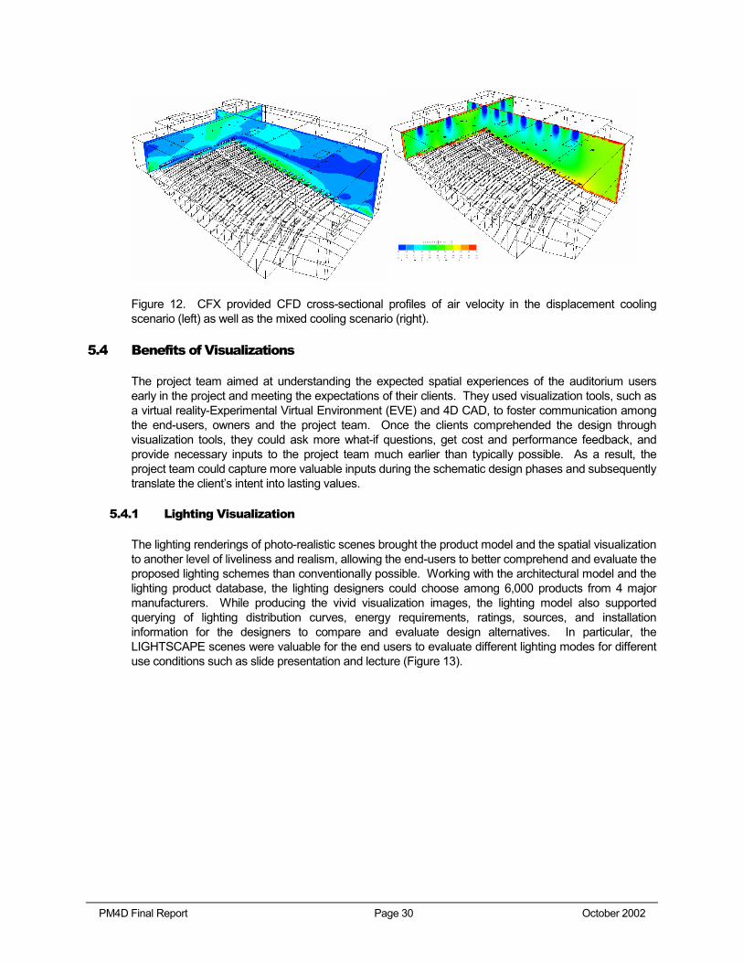
The lighting renderings of photo-realistic scenes brought the product model and the spatial visualization to another level of liveliness and realism, allowing the end-users to better comprehend and evaluate the proposed lighting schemes than conventionally possible. Working with the architectural model and the lighting product database, the lighting designers could choose among 6,000 products from 4 major manufacturers. While producing the vivid visualization images, the lighting model also supported querying of lighting distribution curves, energy requirements, ratings, sources, and installation information for the designers to compare and evaluate design alternatives. In particular, the LIGHTSCAPE scenes were valuable for the end users to evaluate different lighting modes for different use conditions such as slide presentation and lecture (Figure 13).
PM4D Final Report Page 31 October 2002
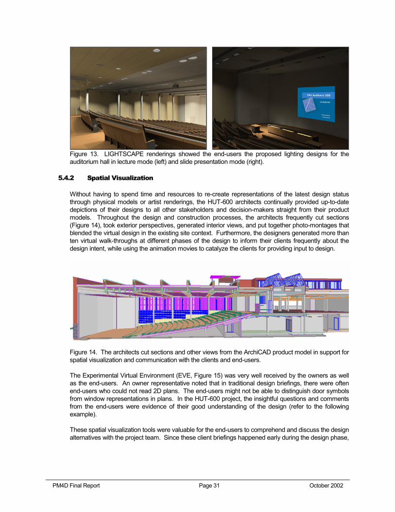
Figure 13. LIGHTSCAPE renderings showed the end-users the proposed lighting designs for the auditorium hall in lecture mode (left) and slide presentation mode (right).
5.4.2 Spatial Visualization
Without having to spend time and resources to re-create representations of the latest design status through physical models or artist renderings, the HUT-600 architects continually provided up-to-date depictions of their designs to all other stakeholders and decision-makers straight from their product models. Throughout the design and construction processes, the architects frequently cut sections (Figure 14), took exterior perspectives, generated interior views, and put together photo-montages that blended the virtual design in the existing site context. Furthermore, the designers generated more than ten virtual walk-throughs at different phases of the design to inform their clients frequently about the design intent, while using the animation movies to catalyze the clients for providing input to design.
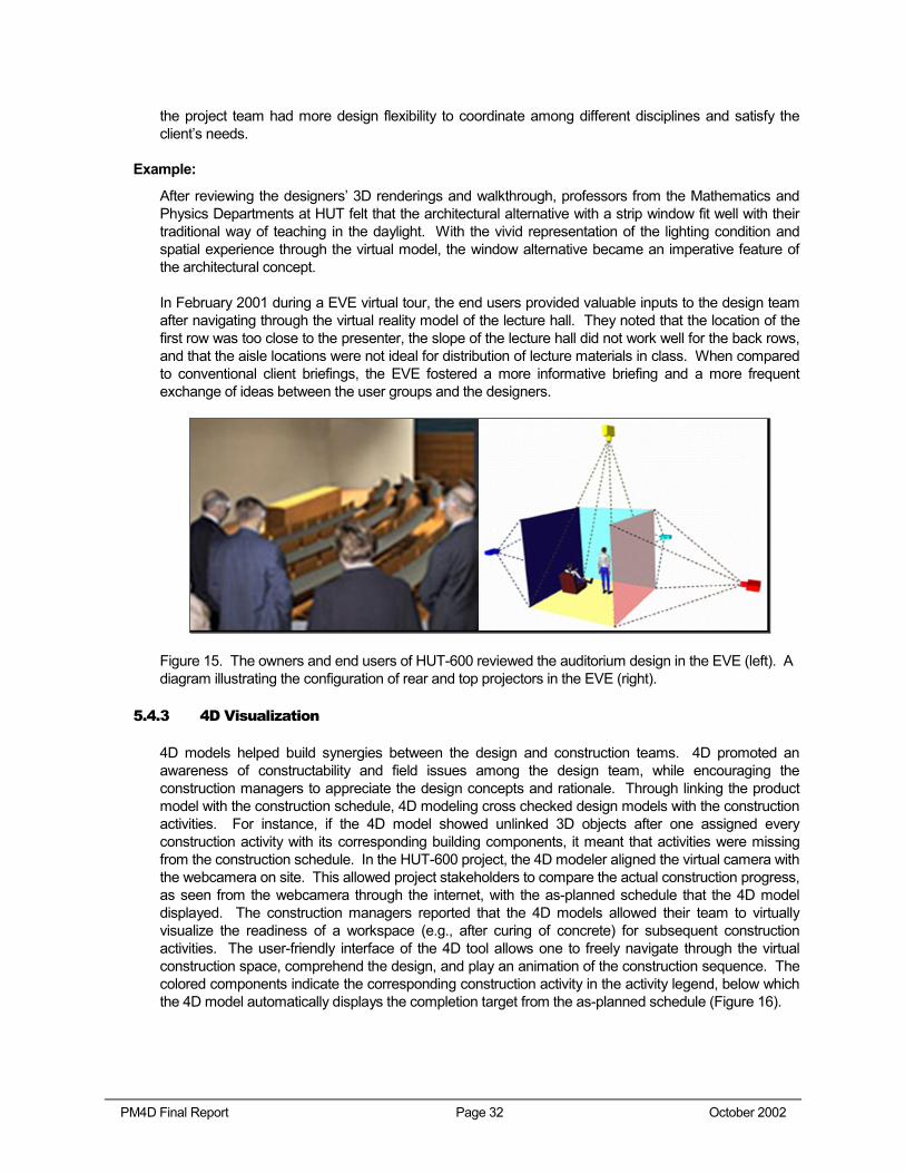
Figure 14. The architects cut sections and other views from the ArchiCAD product model in support for spatial visualization and communication with the clients and end-users.
The Experimental Virtual Environment (EVE, Figure 15) was very well received by the owners as well as the end-users. An owner representative noted that in traditional design briefings, there were often end-users who could not read 2D plans. The end-users might not be able to distinguish door symbols from window representations in plans. In the HUT-600 project, the insightful questions and comments from the end-users were evidence of their good understanding of the design (refer to the following example).
These spatial visualization tools were valuable for the end-users to comprehend and discuss the design alternatives with the project team. Since these client briefings happened early during the design phase,
PM4D Final Report Page 32 October 2002
the project team had more design flexibility to coordinate among different disciplines and satisfy the client’s needs.
Example:
After reviewing the designers’ 3D renderings and walkthrough, professors from the Mathematics and Physics Departments at HUT felt that the architectural alternative with a strip window fit well with their traditional way of teaching in the daylight. With the vivid representation of the lighting condition and spatial experience through the virtual model, the window alternative became an imperative feature of the architectural concept.
In February 2001 during a EVE virtual tour, the end users provided valuable inputs to the design team after navigating through the virtual reality model of the lecture hall. They noted that the location of the first row was too close to the presenter, the slope of the lecture hall did not work well for the back rows, and that the aisle locations were not ideal for distribution of lecture materials in class. When compared to conventional client briefings, the EVE fostered a more informative briefing and a more frequent exchange of ideas between the user groups and the designers.
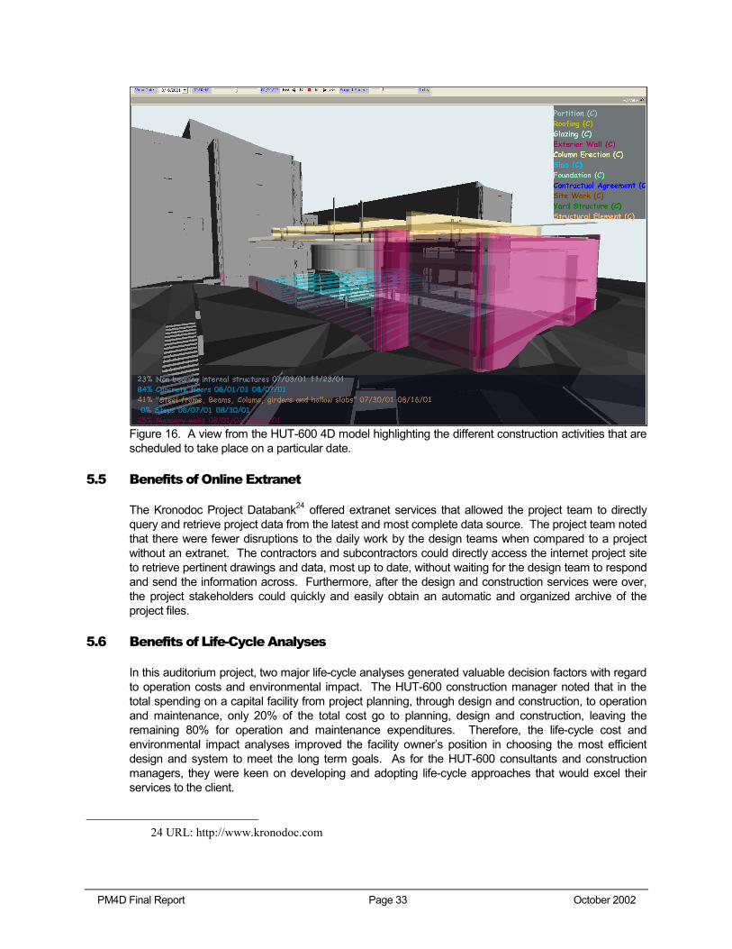
Figure 15. The owners and end users of HUT-600 reviewed the auditorium design in the EVE (left). A diagram illustrating the configuration of rear and top projectors in the EVE (right).
5.4.3 4D Visualization
4D models helped build synergies between the design and construction teams. 4D promoted an awareness of constructability and field issues among the design team, while encouraging the construction managers to appreciate the design concepts and rationale. Through linking the product model with the construction schedule, 4D modeling cross checked design models with the construction activities. For instance, if the 4D model showed unlinked 3D objects after one assigned every construction activity with its corresponding building components, it meant that activities were missing from the construction schedule. In the HUT-600 project, the 4D modeler aligned the virtual camera with the webcamera on site. This allowed project stakeholders to compare the actual construction progress, as seen from the webcamera through the internet, with the as-planned schedule that the 4D model displayed. The construction managers reported that the 4D models allowed their team to virtually visualize the readiness of a workspace (e.g., after curing of concrete) for subsequent construction activities. The user-friendly interface of the 4D tool allows one to freely navigate through the virtual construction space, comprehend the design, and play an animation of the construction sequence. The colored components indicate the corresponding construction activity in the activity legend, below which the 4D model automatically displays the completion target from the as-planned schedule (Figure 16).
PM4D Final Report Page 33 October 2002
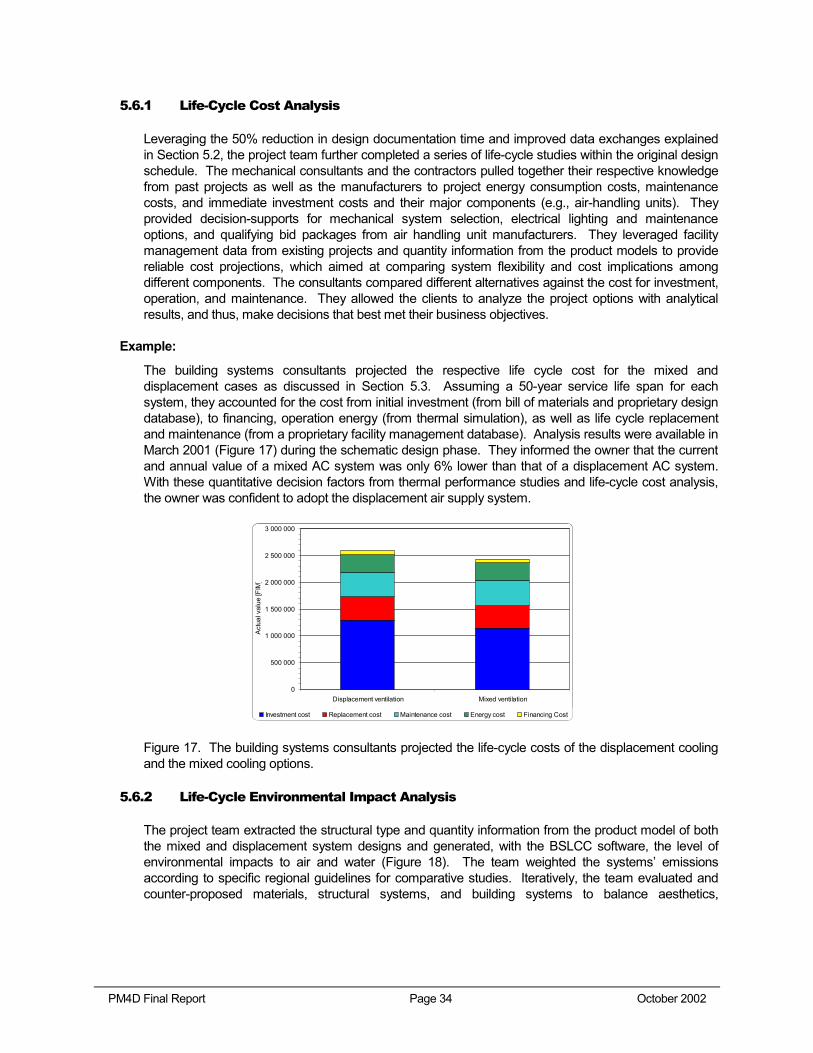
Figure 16. A view from the HUT-600 4D model highlighting the different construction activities that are scheduled to take place on a particular date.
5.5 Benefits of Online Extranet
The Kronodoc Project Databank24 offered extranet services that allowed the project team to directly query and retrieve project data from the latest and most complete data source. The project team noted that there were fewer disruptions to the daily work by the design teams when compared to a project without an extranet. The contractors and subcontractors could directly access the internet project site to retrieve pertinent drawings and data, most up to date, without waiting for the design team to respond and send the information across. Furthermore, after the design and construction services were over, the project stakeholders could quickly and easily obtain an automatic and organized archive of the project files.
5.6 Benefits of Life-Cycle Analyses
In this auditorium project, two major life-cycle analyses generated valuable decision factors with regard to operation costs and environmental impact. The HUT-600 construction manager noted that in the total spending on a capital facility from project planning, through design and construction, to operation and maintenance, only 20% of the total cost go to planning, design and construction, leaving the remaining 80% for operation and maintenance expenditures. Therefore, the life-cycle cost and environmental impact analyses improved the facility owner’s position in choosing the most efficient design and system to meet the long term goals. As for the HUT-600 consultants and construction managers, they were keen on developing and adopting life-cycle approaches that would excel their services to the client.
24 URL: http://www.kronodoc.com
PM4D Final Report Page 34 October 2002
5.6.1 Life-Cycle Cost Analysis
Leveraging the 50% reduction in design documentation time and improved data exchanges explained in Section 5.2, the project team further completed a series of life-cycle studies within the original design schedule. The mechanical consultants and the contractors pulled together their respective knowledge from past projects as well as the manufacturers to project energy consumption costs, maintenance costs, and immediate investment costs and their major components (e.g., air-handling units). They provided decision-supports for mechanical system selection, electrical lighting and maintenance options, and qualifying bid packages from air handling unit manufacturers. They leveraged facility management data from existing projects and quantity information from the product models to provide reliable cost projections, which aimed at comparing system flexibility and cost implications among different components. The consultants compared different alternatives against the cost for investment, operation, and maintenance. They allowed the clients to analyze the project options with analytical results, and thus, make decisions that best met their business objectives.
Example:
The building systems consultants projected the respective life cycle cost for the mixed and displacement cases as discussed in Section 5.3. Assuming a 50-year service life span for each system, they accounted for the cost from initial investment (from bill of materials and proprietary design database), to financing, operation energy (from thermal simulation), as well as life cycle replacement and maintenance (from a proprietary facility management database). Analysis results were available in March 2001 (Figure 17) during the schematic design phase. They informed the owner that the current and annual value of a mixed AC system was only 6% lower than that of a displacement AC system. With these quantitative decision factors from thermal performance studies and life-cycle cost analysis, the owner was confident to adopt the displacement air supply system.
0
500 000
1 000 000
1 500 000
2 000 000
2 500 000
3 000 000
Displacement ventilation Mixed ventilation
Act
ual v
alue
[FIM
]
Investment cost Replacement cost Maintenance cost Energy cost Financing Cost
Figure 17. The building systems consultants projected the life-cycle costs of the displacement cooling and the mixed cooling options.
5.6.2 Life-Cycle Environmental Impact Analysis
The project team extracted the structural type and quantity information from the product model of both the mixed and displacement system designs and generated, with the BSLCC software, the level of environmental impacts to air and water (Figure 18). The team weighted the systems’ emissions according to specific regional guidelines for comparative studies. Iteratively, the team evaluated and counter-proposed materials, structural systems, and building systems to balance aesthetics,
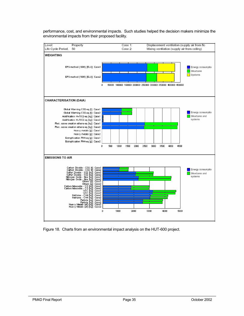
PM4D Final Report Page 35 October 2002
performance, cost, and environmental impacts. Such studies helped the decision makers minimize the environmental impacts from their proposed facility.
Figure 18. Charts from an environmental impact analysis on the HUT-600 project.
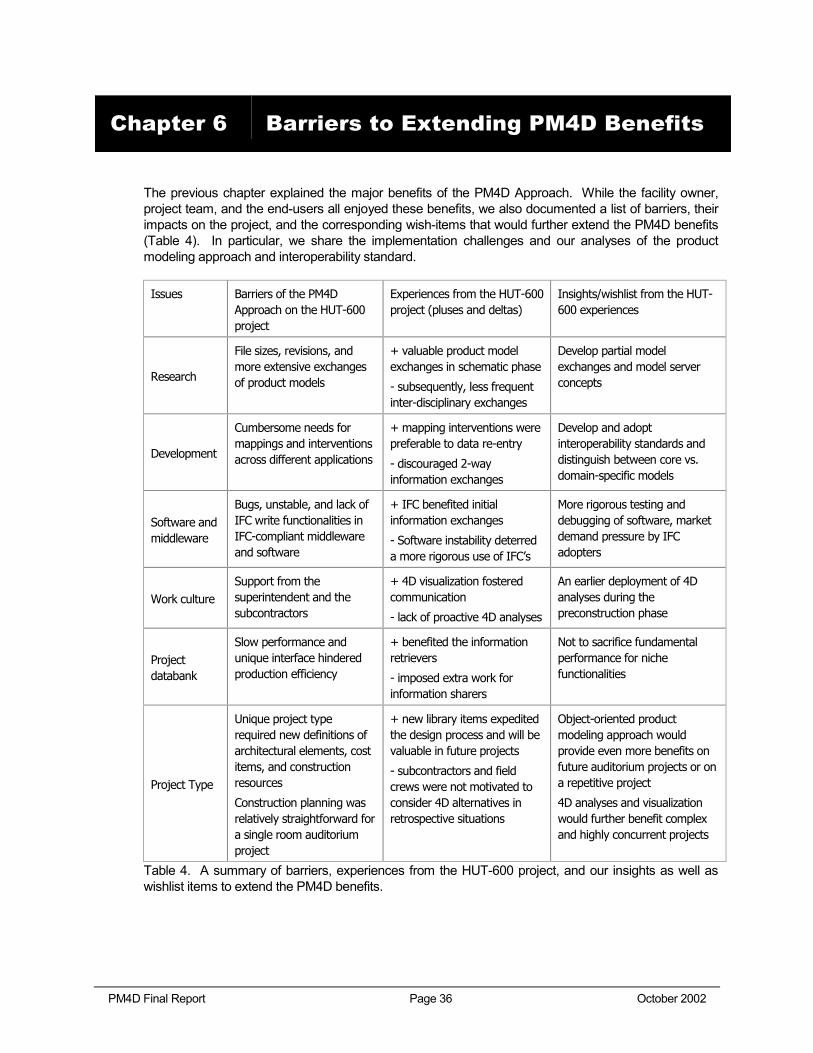
PM4D Final Report Page 36 October 2002
The previous chapter explained the major benefits of the PM4D Approach. While the facility owner, project team, and the end-users all enjoyed these benefits, we also documented a list of barriers, their impacts on the project, and the corresponding wish-items that would further extend the PM4D benefits (Table 4). In particular, we share the implementation challenges and our analyses of the product modeling approach and interoperability standard.
Issues Barriers of the PM4D Approach on the HUT-600 project
Experiences from the HUT-600 project (pluses and deltas)
Insights/wishlist from the HUT-600 experiences
Research
File sizes, revisions, and more extensive exchanges of product models
+ valuable product model exchanges in schematic phase
- subsequently, less frequent inter-disciplinary exchanges
Develop partial model exchanges and model server concepts
Development
Cumbersome needs for mappings and interventions across different applications
+ mapping interventions were preferable to data re-entry
- discouraged 2-way information exchanges
Develop and adopt interoperability standards and distinguish between core vs. domain-specific models
Software and middleware
Bugs, unstable, and lack of IFC write functionalities in IFC-compliant middleware and software
+ IFC benefited initial information exchanges
- Software instability deterred a more rigorous use of IFC’s
More rigorous testing and debugging of software, market demand pressure by IFC adopters
Work culture Support from the superintendent and the subcontractors
+ 4D visualization fostered communication
- lack of proactive 4D analyses
An earlier deployment of 4D analyses during the preconstruction phase
Project databank
Slow performance and unique interface hindered production efficiency
+ benefited the information retrievers
- imposed extra work for information sharers
Not to sacrifice fundamental performance for niche functionalities
Project Type
Unique project type required new definitions of architectural elements, cost items, and construction resources
Construction planning was relatively straightforward for a single room auditorium project
+ new library items expedited the design process and will be valuable in future projects
- subcontractors and field crews were not motivated to consider 4D alternatives in retrospective situations
Object-oriented product modeling approach would provide even more benefits on future auditorium projects or on a repetitive project
4D analyses and visualization would further benefit complex and highly concurrent projects
Table 4. A summary of barriers, experiences from the HUT-600 project, and our insights as well as wishlist items to extend the PM4D benefits.
Chapter 6 Barriers to Extending PM4D Benefits
PM4D Final Report Page 37 October 2002
6.1 Product Model Sharing
In Chapter 4, we explained the motivation for the HUT-600 project team to count on the object-oriented product modeling approach for improving design accuracy and expediting the work processes. We also highlighted the benefits of product models in architectural design, mechanical design, and construction planning in Section 5.1. Throughout the design and construction of the auditorium hall, product models provided consistent benefits in multiple intra-disciplinary applications (i.e., uses within each professional domain). Whereas for inter-disciplinary sharing of product models, in spite of the concrete positive values they demonstrated during the initial exchanges (e.g., readings of architectural models by RIUSKA and by COVE), there were needs for improvement. Specifically, in the following subsections we discuss the lack of guidelines and motivations in organizing product models, the challenges of application-specific input/output requirements, the setback of long one-way conversion processes, and the needs for stronger interoperability.
These product modeling barriers are very consistent with the motivations for an interoperable environment. The barriers such as lack of modeling guidelines, input/output mappings, and one-way conversions call for stronger interoperability support (refer to Section 6.2).
6.1.1 Lack of Modeling Guidelines and Motivations
From the HUT-600 project, we found that the lack of 3D model organization standards as well as clear business motivations could potentially undermine future adoption of the product modeling approach. To our knowledge, there are no local, international, or well-adopted standards for product model organization. When working with 2D CAD designs, Finnish companies follow the regional “HOUSE 90” layer standards. Whereas for 3D models, individual design and construction companies usually follow their own experiences or internal guidelines in organizing 3D layers, setting accuracy or tolerance targets, grouping object hierarchies, and generating layer combinations or view sets. Very often, the organization largely depends on the specific environments and interfaces of the software applications in use (e.g., ArchiCAD separates objects by floors). Although these varying model organization and model creation practices were acceptable in intra-disciplinary 3D applications, they created challenges and rework for the architectural designers in the HUT-600 project. Furthermore, as there were no formal contractual agreements binding the architects to take the responsibility of maintaining a sharable product model, the HUT-600 architects voluntarily took on the responsibilities and the rework in support of the PM4D Approach (e.g., break up the geometry differently to satisfy the calculation requirements of the lighting visualization software).
Building owners and designers should consider allocating design fees for product model organization and maintenance in future projects. Since each discipline uses different product model applications and develops its own preferences, organizations, and input requirements, the HUT-600 architects reported making iterative modifications and adjustments to their product models before the lighting designers, mechanical system consultants, and the construction managers could make productive uses of the models (Figure 19). We further investigate these modifications in the following subsections.
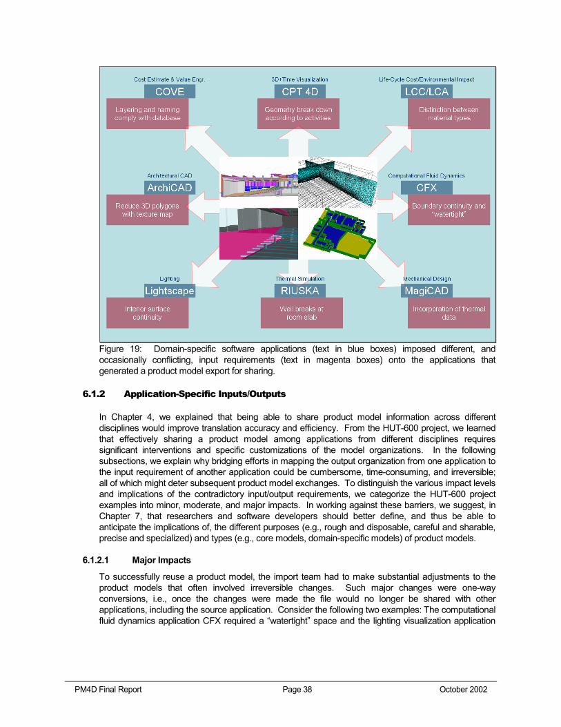
PM4D Final Report Page 38 October 2002
Figure 19: Domain-specific software applications (text in blue boxes) imposed different, and occasionally conflicting, input requirements (text in magenta boxes) onto the applications that generated a product model export for sharing.
6.1.2 Application-Specific Inputs/Outputs
In Chapter 4, we explained that being able to share product model information across different disciplines would improve translation accuracy and efficiency. From the HUT-600 project, we learned that effectively sharing a product model among applications from different disciplines requires significant interventions and specific customizations of the model organizations. In the following subsections, we explain why bridging efforts in mapping the output organization from one application to the input requirement of another application could be cumbersome, time-consuming, and irreversible; all of which might deter subsequent product model exchanges. To distinguish the various impact levels and implications of the contradictory input/output requirements, we categorize the HUT-600 project examples into minor, moderate, and major impacts. In working against these barriers, we suggest, in Chapter 7, that researchers and software developers should better define, and thus be able to anticipate the implications of, the different purposes (e.g., rough and disposable, careful and sharable, precise and specialized) and types (e.g., core models, domain-specific models) of product models.
6.1.2.1 Major Impacts
To successfully reuse a product model, the import team had to make substantial adjustments to the product models that often involved irreversible changes. Such major changes were one-way conversions, i.e., once the changes were made the file would no longer be shared with other applications, including the source application. Consider the following two examples: The computational fluid dynamics application CFX required a “watertight” space and the lighting visualization application
PM4D Final Report Page 39 October 2002
LIGHTSCAPE crashed if any geometry penetrated through the interior surfaces of interest. Neither the concept “watertight” nor the interior breakage was present in the original architectural model.
These were specific disciplinary requirements and specific application views that required special modifications of the product model. The major impact was that once such an intervention took place, the product model had undergone an irreversible domain-specific transformation, making subsequent data sharing very difficult, if not impossible. As a result, whenever there is a design change—minor or major, one has to go through all the conversions to make the product model meaningful to its downstream application (e.g., different design alternatives for thermodynamics application). On the other hand, it is very difficult for one to reuse or share any new and added information with other applications (e.g., between thermodynamics and lighting applications).
6.1.2.2 Moderate Impacts
The project team had to carry out a number of extra procedures and intervening modifications to make their product models sharable. However, once additional information was created, it was very difficult for the exporting parties to read and share them in return. For instance, LIGHTSCAPE required a higher level of precision in all joints or connections than what the architectural model offered, causing the architects to modify many joints and connections that were not precisely meeting one another. Another example was that the TARMO cost database required a more detailed identification of each element (e.g., whether an object was internal or external, bearing or non-bearing, what the construction assembly was, etc.) than the architect’s specifications of the 3D objects in ArchiCAD. Similarly, without specific material description or construction assembly, BSLCA required manual re-definition of data to perform environmental assessment. Finally, the 4D CAD applications required object breakdowns and groupings corresponding to the construction or installation sequence, rather than the architectural breakdowns.
6.1.2.3 Minor Impacts
For the differing exchange requirements on a product model that we categorize as minor in impacts, it was relatively simple and quick to amend the model export for the importing application. For example, the architects had to discuss the representation of the construction joints with the construction managers as they exported the product model from ArchiCAD to COVE. In ArchiCAD, the architect did not show the construction joints initially as they utilized texture maps to simplify the actual breakdown of geometry. This approach reduced the polygon counts for better visualization performance. However in COVE, construction managers relied on the proper separation of construction joints for scheduling, cost estimating, and 4D modeling.
In another example, the building systems consultant required the architects to break the exterior walls in the product model at the sloping floor level, instead of extending the wall all the way down to the foundation slab. In this scenario, the architect modeled the wall in accordance to the construction separation, whereas the consultants needed the wall to break with the internal space for RIUSKA to provide an accurate thermal simulation. An extension of the exterior wall beyond its thermal zone, as the architect had modeled it, would alter the insulation calculation in RIUSKA and result in a lower cooling demand. In both cases, it was relatively easy though to make the necessary adjustments, and the sharing of product models was not seriously affected.
6.1.3 Time-consuming One-Way Conversion Processes
As introduced in the previous sections, the application of product models in the HUT-600 project involved several one-way conversions, which were time-consuming and inflexible for subsequent modifications and sharing. They often involved flattening object parameters (e.g., showing a proxy
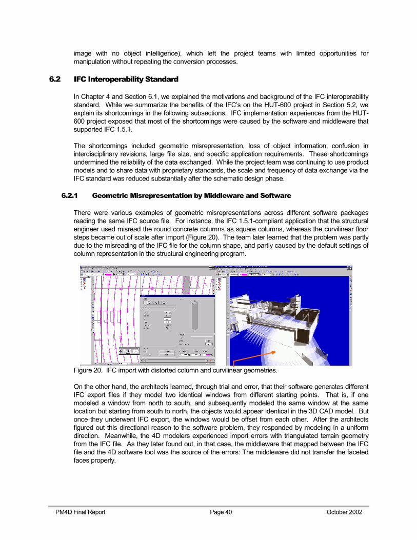
PM4D Final Report Page 40 October 2002
image with no object intelligence), which left the project teams with limited opportunities for manipulation without repeating the conversion processes.
6.2 IFC Interoperability Standard
In Chapter 4 and Section 6.1, we explained the motivations and background of the IFC interoperability standard. While we summarize the benefits of the IFC’s on the HUT-600 project in Section 5.2, we explain its shortcomings in the following subsections. IFC implementation experiences from the HUT-600 project exposed that most of the shortcomings were caused by the software and middleware that supported IFC 1.5.1.
The shortcomings included geometric misrepresentation, loss of object information, confusion in interdisciplinary revisions, large file size, and specific application requirements. These shortcomings undermined the reliability of the data exchanged. While the project team was continuing to use product models and to share data with proprietary standards, the scale and frequency of data exchange via the IFC standard was reduced substantially after the schematic design phase.
6.2.1 Geometric Misrepresentation by Middleware and Software
There were various examples of geometric misrepresentations across different software packages reading the same IFC source file. For instance, the IFC 1.5.1-compliant application that the structural engineer used misread the round concrete columns as square columns, whereas the curvilinear floor steps became out of scale after import (Figure 20). The team later learned that the problem was partly due to the misreading of the IFC file for the column shape, and partly caused by the default settings of column representation in the structural engineering program.
Figure 20. IFC import with distorted column and curvilinear geometries.
On the other hand, the architects learned, through trial and error, that their software generates different IFC export files if they model two identical windows from different starting points. That is, if one modeled a window from north to south, and subsequently modeled the same window at the same location but starting from south to north, the objects would appear identical in the 3D CAD model. But once they underwent IFC export, the windows would be offset from each other. After the architects figured out this directional reason to the software problem, they responded by modeling in a uniform direction. Meanwhile, the 4D modelers experienced import errors with triangulated terrain geometry from the IFC file. As they later found out, in that case, the middleware that mapped between the IFC file and the 4D software tool was the source of the errors: The middleware did not transfer the faceted faces properly.
PM4D Final Report Page 41 October 2002
6.2.2 Loss of Object Information
One of the key benefits of adopting a product modeling approach is the capability to specify, query, and modify properties of 3D objects. The architects followed this object-oriented modeling approach. They specified parametric properties of windows, seating furniture, and lighting fixtures in the model, and saved them as parametric library objects for reuse or reconfiguration in design iterations. When dealing with ArchiCAD’s library objects in the HUT-600 project, the IFC files ignored all non-geometric object parameters and replaced object intelligence with mere geometric representation. This loss of information also happened to objects in the mechanical exports, where components’ properties such as efficiency rating, flow rate, and device identification were lost in their proxy representations. As IFC’s continue to evolve, some of these challenges have been addressed (e.g., the definition of HVAC objects) in more recent releases of IFC (e.g., IFC 2x).
6.2.3 Confusion in Interdisciplinary Revisions
Initially, the exchange of IFC-based files was satisfactory. However, whenever the architects revised the 3D model and exported an updated IFC file, the architectural software regenerated a new set of space identifiers, which would then confuse the importing software. For example, when the mechanical engineers received the revised IFC file from the architects in the second design iteration, they either had to investigate what the architects had changed and manually synchronize the new design data with their previous analytical data, or they had to regenerate the simulation of the entire building. This confusion in file revision, caused by the exporting software application, adversely impacted the effectiveness of IFC’s during the design development phase.
6.2.4 Large File Size
A consequence of losing parametric object information is an increase in IFC file size. We compared the file sizes of various component objects (e.g., a wall assembly, windows, and the overall building) in both native and IFC formats. The IFC representation files were up to five times the size of the original file formats. The representation of triangulated site terrain objects was not efficient either. This became a major burden on both computer hardware, software, and networks, adversely impacting the manipulation and performance of subsequent analyses and modeling efforts.
PM4D Final Report Page 42 October 2002
7.1 Recommendations
To gain further insights into the benefits and pragmatic implications of IFC’s and the product modeling approach, we recommend that the industry, researchers, and software developers should continue to team up for live pilot projects. We make the following recommendations to the main project participants.
7.1.1 Building Owners
In the HUT-600 project, the owner’s full support for product modeling approaches and an early assembly of cross-disciplinary project teams were key to the project success. In selecting project teams or when making project decisions, we suggest to building owners to be aware of operation and maintenance issues, the opportunities for improvements in the life-cycle performance during early project phases, and the motivations for the PM4D Approach.
In light of the improved efficiency and higher quality in design documentation and subsequent benefits from the project life-cycle, made possible by the product modeling approach, we recommend building owners, and designers, to consider allocating design fees for the organization and maintenance of product models in future projects.
7.1.2 Designers and Builders
The PM4D Approach demonstrated how project teams could differentiate themselves by utilizing object-oriented product models to expedite routine jobs and focus on more value-adding work. We suggest to project teams to clearly define roles, privileges, responsibilities, and revision schedules in sharing product models and interoperable project data. Meanwhile, designers should consider shifting their business strategies from the construction documentation phase in conventional practice to early project planning phases and to developing an informative product model. Furthermore, when working with product models, the project teams should evaluate the specific model types and purposes and thus, tailor their efforts and expectations accordingly.
In terms of model types, the project team should evaluate whether a model is core or domain-specific. As introduced in Section 6.1, core models contain data that are relevant and sharable to many parties; whereas domain-specific models address specific views and technical information that only interest particular specialty disciplines. We suggest to project teams to make core models interoperable, while agreeing upon the responsibility and methods to make domain-specific models available when needed. Taking the HUT-600 case as an example, a core model should include the spatial objects, basic structural elements, material information, etc., whereas the domain-specific models would represent the “thermal views”, “lighting views”, etc. Consequently, the architects should then focus on developing and coordinating the core model, and not on altering the core model in support for the disciplinary views.
Besides model types, it is also important to define the purpose of a model early on. Project teams may consider categorizing product models as rough, careful, and precise. Rough models are quick and “keep it simple” models. Modelers may sacrifice proper organization and object parameters since the models are only meant for quick studies (e.g., massing) and are discarded afterwards. On the other
Chapter 7 Recommendations and Conclusions
PM4D Final Report Page 43 October 2002
end of the scale, precise models may require a lot more time, accuracy, and special organization to meet the demands of specialized applications (e.g., computational fluid dynamics simulations, lighting studies). In spite of the efforts spent on constructing precise models, project teams should be aware that these models may not be easily sharable. Since the specific organization in a precise model can be very domain-specific, substantial rework and adjustments are required to make it sharable with other disciplines. Hence, we advise project teams to create accurate core models that allow the maximum amount of extensibility.
7.1.3 Researchers
Analyzing the IFC implementation on the HUT-600 project, we find that partial model exchanges, support for interdisciplinary revisions, IFC schema extensibility, and the concept of “core model” versus “domain-specific model” are research areas of high importance.
Partial Data Exchanges:
The implementation challenges of large file size, revision handling, and specific application requirements motivate our call for further research in partial data exchanges. This will allow each discipline to read the data that are pertinent to them, reducing the time and the burden to import the IFC file containing “all” project data. Furthermore, partial data exchanges have the potential of minimizing the risk of erasing or corrupting project data that is not relevant for a particular application.
Model Servers:
Database severs for product models can possibly solve the challenges of interdisciplinary revisions while complementing the partial data exchange initiatives. Adachi (2001) discusses and illustrates how application users could share and access a remote database with IFC object models through XML, SOAP (Simple Object Access Protocol) or STEP (Standard for the Exchange of Product Model Data) over the internet25. Such a model server approach can better define the ownership of each item of information, support a more dynamic and collaborative approach to data sharing, and facilitate better access and privilege controls.
Schema Extensibility:
In response to the loss of parametric object information, we suggest that the IFC standard developers consider referencing parametric modeling formats (e.g., GDL26) and manufacturers’ online product catalogues (e.g., through XML) rather than taking a sole “ground-up” approach in which IFC structures all project data according to its schema.
7.1.4 Software Developers
The unreliable performance of IFC-compliant software and middleware was a major hindrance to a more extensive use of the IFC files. We found that software developers sometimes interpreted the IFC standards incorrectly, and had not debugged their software’s IFC functionality sufficiently. To enable professionals to use IFC files commonly, software vendors will need to interpret the IFC standard more carefully and produce more reliable IFC functionality.
25 URL: http://cic.vtt.fi/projects/ifcsvr 26 URL: http://www.gdltechnology.com
PM4D Final Report Page 44 October 2002
7.1.5 All Parties
In terms of development, we believe that reliability in IFC-compliant middleware and software as well as more IFC exporting capabilities are essential for consideration by software vendors in the architecture, engineering, and construction domains. At the same time, open sharing of information poses challenges to the contributors’ proprietary information. Various project team members from the HUT-600 project expressed concerns that they may become liable for their internal data, process means, and company approaches once this information is shared among external collaborators. Protecting the internal data of a company jeopardizes the “intelligence” embodied in a shared IFC file. There is a need to secure privileges, release liability, and define both ownership and responsibility of shared information.
7.2 Conclusions
We conclude from the HUT-600 project experiences that the PM4D Approach is capable of expediting conventional design practices and promoting life-cycle approaches to facility design. In spite of the technical wish-list items that could further benefit future project collaborations, project examples demonstrated that owners can already choose among comprehensive life-cycle alternatives, end-users can provide input to the facility design in a timely manner, and designers and builders can differentiate themselves from their competitors with higher efficiency, quality, and more effective application of their expertise. Based on our experience on the project, we would like to offer the following concluding messages.
7.2.1 Implications of Pilot Industrial Application of IFC’s
The design and construction of the HUT-600 project provided the testing ground for a pilot application of the IFC. With software and middleware that were compatible with IFC release 1.5.1, the HUT-600 project team benefited from the extensive exchanges of 3D geometries, spatial information, thermal values, and material properties among different software applications and disciplines. IFC’s minimized data re-entry, increased accuracy of information exchange, and reduced design time during the schematic design phase. The pilot implementation provided researchers and developers with insights and practical implications about needs for improvements for an information exchange standard and interoperable software. In particular, the project team experienced geometric misrepresentation and unstable performances by IFC-compliant middleware and software, loss of object information, confusion in interdisciplinary design revisions, large file size, and requirements by various applications for specific product model representation and organization. While the IFC’s are evolving and starting to address some of the pragmatic challenges (e.g., IFC2x solves HVAC object definition barriers by assigning real IFC objects, which contain HVAC attributes and reduce file sizes), we consider software robustness, partial data exchanges and model server technologies as keys to extending the benefits and improving the reliability of IFC’s.
7.2.2 Capitalize on Early Project Opportunities
In spite of the schedule constraints and a fast-track approach, the HUT-600 project team capitalized on the PM4D Approach and Processes to generate three design and two life-cycle alternatives. The product modeling approach provided consistent benefits such as higher efficiency and better quality in multiple intra-disciplinary applications. It allowed the project team to quickly perform routine jobs and divert more time and attention to higher value work. The shift from performing routine to high-value work reduced project risks. Higher efficiency, better design and construction quality, and more informative decision supports were evidenced by various benefit examples (e.g., early generation of a reliable budget, valuable client input during the schematic phase, early availability of multidisciplinary

PM4D Final Report Page 45 October 2002
analyses, availability of recommendations that covered life cycle performance, maintenance, energy, and environmental factors, etc.). In relation to the Level of Influence diagram (Chapter 5, page 20), pertinent decision factors and multiple project alternatives were available early during the schematic design phase, which allowed the owners to make informed decisions with relatively high impact and relatively low costs.
PM4D Final Report Page 46 October 2002
Adachi, Y. (2001). “IFC Model Server Development Project” VTT and SECOM, http://cic.vtt.fi/projects/ifcsvr/.
Building Lifecycle Interoperable Software (BLIS). (1999). “Project Brief” Project Info, http://www.blis-project.org/index2.html.
International Alliance of Interoperability (IAI). (1995). “About IAI” Background, http://iaiweb.lbl.gov.
Kam, C.; Fischer, M.; Hänninen, R.; Lehto, S.; and Laitinen, J. (2002). "Capitalizing on Early Project Opportunities to Improve Facility Life-Cycle Performance." Proceedings of the 19th International Symposium on Automation and Robotics in Construction, William Stone (Editor), National Institute of Standards and Technology, Gaithersburg, MD. September 23-25, 2002, pp. 73-78.
Kam, C. and Fischer, M (2001). “Industry Foundation Classes and 3D/4D Models.” Presentation at CIFE Summer Program 2001, Stanford University, Stanford, CA, September 10.
Kam, C. and Fischer, M (2001). “Experiences from HUT-600 Auditorium Project.” Presentation at VERA Seminar, Helsinki, Finland, November 20.
Paulson, B. (1976). "Designing to Reduce Construction Costs." Journal of the Construction Division, ASCE, Vol. 102, No. CO4, Proc. Paper 12600, December, pp. 587-592.
SPADEX (2001). “Final Report of the SPADEX Project” Information Networking in the Construction Process-VERA Program, http://cic.vtt.fi/vera/publications.htm.
Staub-French, S. and Fischer, M. (2001). “Industrial Case Study of Electronic Design, Cost, and Schedule Integration.” CIFE Technical Report 122, Stanford University, Stanford, CA.
References
PM4D Final Report Page 47 October 2002
From Seppo Lehto, Senate Properties, Finland:
• We will continue to implement the use of product model, and have further development projects with product models and virtual buildings.
• We have contacts and collaboration with all product model software vendors active in Finland.
• We have called for design/project management tenders where product modeling is a requirement.
• We are making a comprehensive review of "project databanks" in Finland.
• We try to implement product model as added value to the client (Ateneum art museum).
• We have a project where we try to implement product model in the operation and maintenance phase of the capital facility.
• We organized a seminar for our construction managers in October, 2002 where one item discussed was "new design tools and processes" and we also organized for all participants a visit to the experimental virtual environment in HUT.
• But we also require business benefits resulting from the use of product model. Our opinion is that there must be several (3-4) areas where the product model can be implemented in order for us to justify the initial extra work required to establish the product modeling for the project on question.
After Thoughts from Project Participants
PM4D Final Report Page 48 October 2002
From Markku Jokela, Olof Granlund Oy, Finland:
Granlund has invested a lot in development of integrated design and product-model-based tools. As a result of many years of effort, we have an IFC-compliant software family—from modeling of buildings to various simulations and to visualization for real project work. In addition, we have developed and documented a new design process for product modeling and a related design documentation model. We call it the "Granlund Design model". Our whole design team from project managers to engineers and drafters has received personal training to use the tools and learn the new process. Of course, there is still a lot to do, but already in our current design process we model nearly all bigger buildings in the schematic design and continue with the models in the detailed design.
The benefits of the product-model-based approach result in the first place from improved design quality. The client feedback, especially from the visual and understandable results of the simulations to facilitate comparisons of design alternatives, and from related systematic design documentation, has been very positive. After experiencing the advantages of the product-model-based approach in practical consulting business, we are confident of focusing our development strategy more and more on this concept. As minor comments to the final report, to use IFC-compliant software for simulations, like Granlund currently does, it is not a matter of major importance to send back to the product model the simulation results or similar disciple-specific data. In the first phase, we would be quite happy with the architect's core model (if available and correct), because we can avoid modeling by ourselves. In hectic projects this may be an important need for using sophisticated tools in the early phase of design. Of course, in the future, reverse data exchange will give more additional value. Furthermore, one may judge, if a perfect and inclusive model with all possible design details is the target of development. We can get the base information quite well from the core model. If the model is too heavy, it sets too many requirements for IFC compliancy of applications. In other words, much of the detailed information (like window shields etc.) can easily be added manually in the respective applications.
After Thoughts from Project Participants
PM4D Final Report Page 49 October 2002
Senate Properties
Kari Alatalo <[email protected]>
Auli Karjalainen <[email protected]>
Olof Granlund Oy
Reijo Hänninen <[email protected]>
Markku Jokela <[email protected]>
YIT Corporation
Olli Nummelin <[email protected]>
Solibri, Inc.
Dr. Jarmo Laitinen <[email protected]>
A-Konsultit
Jyrki Iso-Aho <[email protected]>
CIFE, Stanford University
Professor Martin Fischer <[email protected]>
Calvin Kam <[email protected]>
Contacts