Embed Size (px)
Citation preview
Tribology Online, 6, 1 (2011) 10-18. ISSN 1881-2198
DOI 10.2474/trol.6.10
Article
Prediction of Dynamic Coefficients of Bump-Type Foil Bearings with Bumps
Considered as Link-Spring Structures
Kai Feng* and Shigehiko Kaneko
Department of Mechanical Engineering, The University of Tokyo 7-3-1 Hongo, Bunkyo-ku, Tokyo 113-8656, Japan *Corresponding author: [email protected]
( Manuscript received 1 July 2009; accepted 16 October 2009; published 31 January 2011 )
( Presented at the World Tribology Congress 2009, Kyoto, 6-11 September, 2009 )
Bump-type foil bearings have demonstrated excellent performance in service experiences in recent 30 years. Due to their special structures, the performance prediction models must couple the air pressure with the elastic deflection of the compliant foil structure. The solution of air pressure has been well settled in the hydrodynamic lubrication theory, while the deflection of foils now still cannot be accurately solved due to the mechanical complexity of the corrugated bump structure. A theoretical model, link-spring model, was developed to predict the structure characteristics of foil strips in a previous work. Effects of four factors, i.e., the elasticity of the bump foil, the interaction forces between bumps, the friction forces at contact surfaces, and the local deflection in the top foil, had been taken into consideration. In this investigation, based on the link-spring model, a perturbation approach is used to determine the dynamic characteristics of bump-type foil bearings. The calculations have been performed with different meshes. And the accordant results show that the calculation is independent on the mesh. The effects on the dynamic coefficients of the friction forces and radial clearance are also evaluated using the perturbation method. Keywords: gas foil bearing, dynamic coefficients, bump foil
1. Introduction
Gas Foil Bearings (GFBs) with the ability operating at high rotating speeds and temperatures are of increasing interesting in recent years and supposed to have the potential to apply over a wide variety of turbomachinary ranging from turboexpander and compressors to numerous gas turbine engines1). The applications of gas foil bearing are hindered for the lack of enough load carrying capacity and damping due to the low viscosity of air. To deal with this problem, several foil-bearing designs have been proposed and resulted in significant improvements in bearing performances. Bump-type foil bearings, which have been reported to operate at temperatures up to 810 oC and at the rotational speed as high as 70 krpm, are considered as the best structure for GFBs1-4). The bump-type foil bearing consists of two parts, a smooth top foil acting as the bearing surface and a flexible corrugate bump foil, which is supporting the top foil to provide elastic deflection and frictional damping. The hydrodynamic film, generated by the rotation of the rotor, acts on the top foil and the elastic structure to force them to deform, resulting in a larger
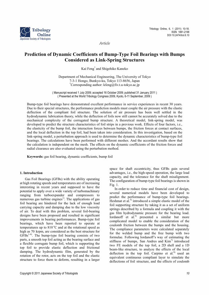
space for shaft eccentricity, thus GFBs gain several advantages, i.e., the high-speed operation, the large load capacity, and the tolerance for the shaft misalignment. The configuration of bump-type foil bearings is shown in Fig. 1.
In order to reduce time and financial cost of design, several numerical models have been developed to predict the performance of bump-type foil bearings. Heshmat et al.5) introduced a simple elastic model of the foil supporting structure by taking it as a set of uniform springs described by a formula and coupling it with the gas film hydrodynamic pressure for the bearing load. Iordanoff et al.6) presented a similar but more complicated model to enable the consideration of the coulomb friction between the bumps and the housing. The compliance parameters were calculated separately for the welded bump and the free bump with two formulae. Following Iordanoff’s way of estimating the stiffness of bumps, San Andres and Kim7) introduced two FE models of the top foil, a 2D shell and a 1D beam-like structure, to analyze the effects of the local deflection in the top foil. Carpino et al.8) used an equivalent continuous compliant layer to simulate the deflections of foil structure, and the effects of coulomb
Copyright © 2011 Japanese Society of Tribologists 10
Prediction of Dynamic Coefficients of Bump-Type Foil Bearings with Bumps Considered as Link-Spring Structures
friction between the bumps and the top foil, and the bumps and the housing were taken into consideration. Le Lez et al.9) presented a theoretical model of the bump strip by treating each bump as a structure of three elementary springs, in which the friction forces of foil structure as well as the interaction forces between bumps was taken into account
The effects of the friction forces in bump-type foil bearings had been well studied by Ku in a series of research works. Ku and Heshmat10) developed a theoretical model of the foil structure to predict the coulomb damping and the stiffness taking into consideration the friction forces between bump foils and the housing or the top foil, as well as the local interaction forces among bumps. And the model was validated by an experimental investigation11). After that, the curvature effect of journal bearings was also appended to the model. The structural stiffness was computed based on the perturbation of the journal center with respect to its static equilibrium position12,13). However, this model is too complicated to be applied by other researchers.
Generally, there is an assembly preload of foils in bump-type foil bearings, which makes the foil bearings at rest not have a perceivable gap between the top foil and the shaft surface. Radil et al.14) conducted an experimental investigation about the effects of the radial clearance variations on the load capacity of gas foil bearings. And they found that the radial clearance had a direct impact on the performance of gas foil bearings. Kim and San Andres15,16) used a constant assembly radial clearance to simulate the preload of foils in the theoretical modeling.
In this study, the foil structure of bump-type foil bearing is described using the link-spring model presented in a previous research. An approach with the perturbation of journal with respect to a small displacement about its equilibrium position is used for the prediction of dynamic coefficients of foil bearings. The synchronous stiffness and damping coefficients as well as the frequency dependent stiffness and damping coefficients are presented. The effects of friction forces and the radial clearance on the dynamic coefficients are also discussed.
Fig. 1 Schematic view of bump-type foil bearings
2. Theoretical analysis
2.1. Reynolds’ equation Reynolds’ equation, which is used to calculate the air
film pressure, is given in non-dimensionless form as
3 32
ph pp pph ph
tz z
h (1)
with the following relationships, 2
6, , , , ,
a a
p h z R Rp h z t t
p C R p C
.
Since the film thickness consists of two parts in foil bearings, the film thickness is written as
min
,1 cos( )
zh
C
(2)
where ε is the shaft eccentricity. δ(θ, z) is the foil deflection. C is the nominal radial clearance. And, θmin is the angular position of the minimum film thickness.
The static load of the bearing is obtained with the integral of the air pressure p .
2 2
2, tan x
x y La y
FWW F F
p R F (3)
where xF and yF denote the dimensionless
bearing force along the horizontal and the vertical direction, expressed as:
DL
DLa
y
x
DL
DLa
xx
zddpRp
FF
zddpRp
FF
/
/
360
02
/
/
360
02
))cos((1
)sin(1
(4)
2.2. Perturbation method Perturbation method has been very successful in
accurately predicting dynamic coefficients of foil bearings17). The same approach is used in this study. A small displacement ,x y and a small
velocity ,x y are assumed to perturb on the journal
at the equilibrium position. The corresponding variables due to the perturbation can be expressed in Taylor series expansion at the equilibrium position by ignoring the higher order term 17):
0 0 0 00
x x xx xy xx xy
y y yx yy yx yy
F F K K C Cx y x y
F F K K C C
0
0
0
,x x y y
x x y y
x x y y
p p p X p X p Y p Y
h h h X h X h Y h Y
X X Y Y
(5)
where the Kmm and Cmm are the stiffness coefficients and the damping coefficients of bearings. The equilibrium position is indicated by subscript “0”.
According to the coordinate system shown in Fig. 1, the dimensionless film thickness, shown in Eq.(2), can be transferred to x-y coordinate system.
0 01 cos sinh Y Y X X (6)
Japanese Society of Tribologists (http://www.tribology.jp/) Tribology Online, Vol. 6, No. 1 (2011) / 11
Kai Feng and Shigehiko Kaneko
For ,X Y and , X Y are arbitrary, we
obtain
sin ;
cos ;
x x x
y y y
h S h S
h S h S
x
y
. (7)
After substituting the above variables into Reynolds’ equation, we can gain the two sets of simultaneous equations, which can be solved separately for
, , ,x x x xp p h h and , , ,y y y yp p h h . The equations are
numerically solved in finite difference form.
0 0 0 0
0 0 0 0
{ , } 2
sin
{ , } 2
x x x x x
x f x f x
x
x x x x x
x f x f x
R p h p h p h p h p h
p K K h
R p h p h p h p h p h
p K K h
x
(8)
0 0 0 0
0 0 0 0
{ , } 2
cos
{ , } 2
y y y y y
y f y f y
y y y y y y
y f y f y
R p h p h p h p h p h
p K K h
R p h p h p h p h p h
p K K h
y
(9) where the left-hand side operator is
3 3 20 00 0 0 0 0
3 3 20 00 0 0 0 0
{ , } 3
3
p pR p h h p h
p pp h h p h
z z z z
.
2.3. Model of foil bearing structure The foil structure of bump-type foil bearings is
composed of two parts, the corrugated bump foil and the smooth top foil. Each bump is replaced with two rigid links and a horizontally spaced spring, as shown in Fig. 2. The segments between bumps are also treated as rigid links. All joints at the ends of the links could rotate freely. It is very important to note that there is a relationship between the horizontal deflection and the vertical deflection of each bump as well as the corresponding forces, because the links are rigid. Thus, each link-spring structure (bump) can be simplified as an equivalent vertical spring.
Fig. 2 Link-spring model of bump-type foil bearings
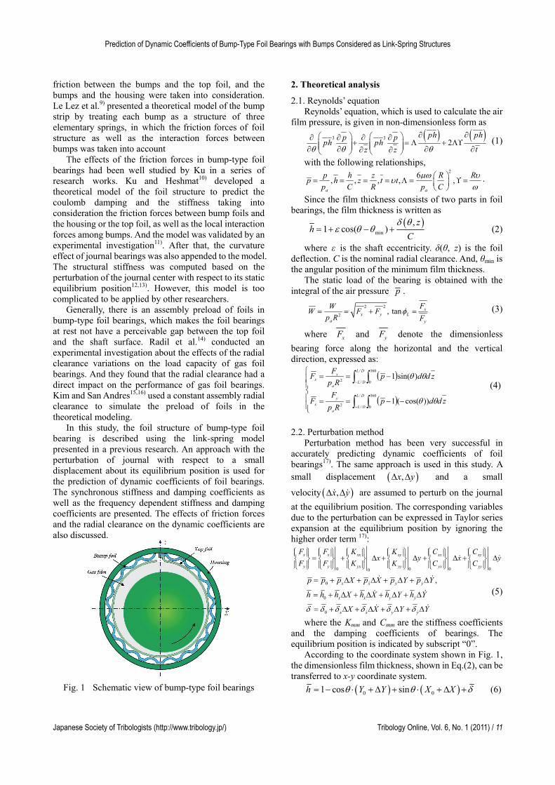
Fig. 3 Assembly of global stiffness matrix with bump stiffness
The top foil is modeled as a thin plate, and the deflection is calculated with the finite element method. Rectangular element with 4 nodes and 12 degrees of freedoms is used to mesh the top foil. The equivalent stiffness along the vertical direction is appended to the stiffness matrix of the top foil at the appropriate places to form the global stiffness matrix, as shown in Fig. 3. The complete link-spring model is presented in Ref. [18].
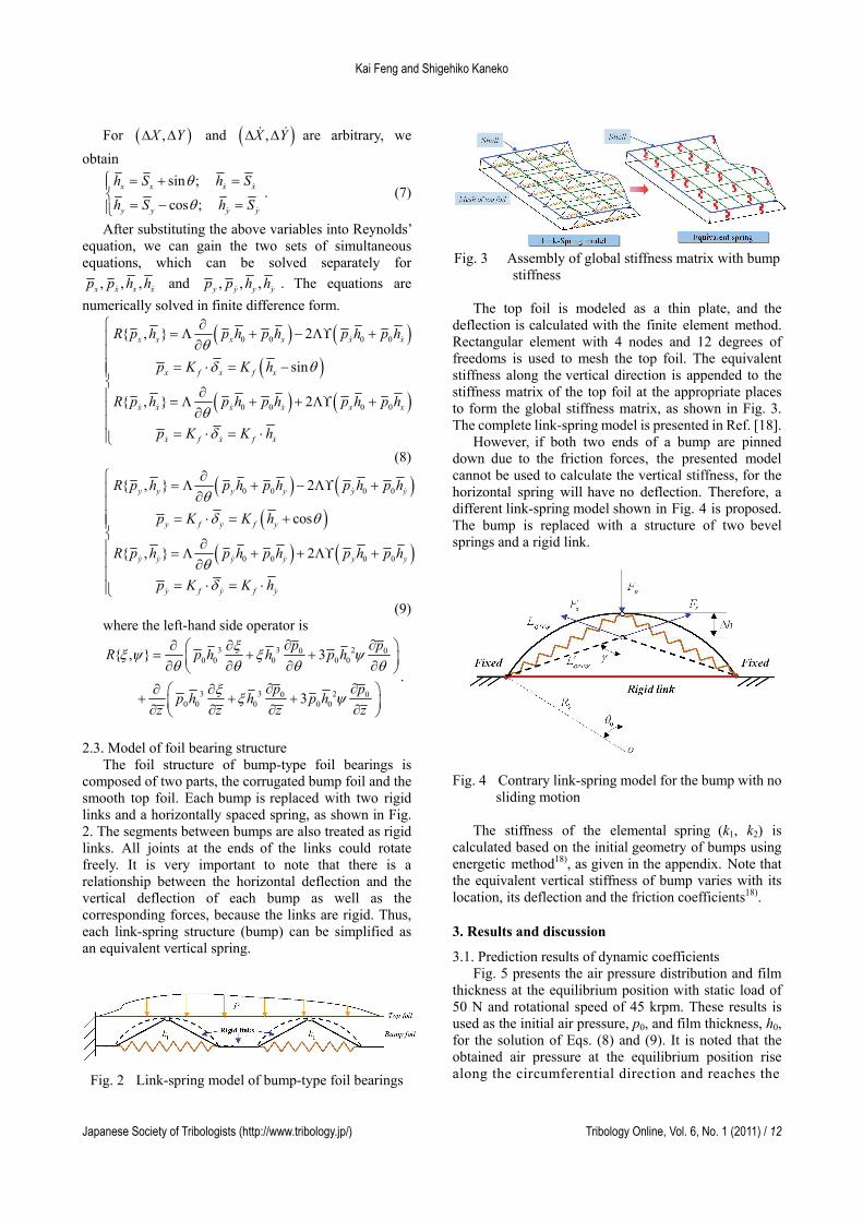
However, if both two ends of a bump are pinned down due to the friction forces, the presented model cannot be used to calculate the vertical stiffness, for the horizontal spring will have no deflection. Therefore, a different link-spring model shown in Fig. 4 is proposed. The bump is replaced with a structure of two bevel springs and a rigid link.
Fig. 4 Contrary link-spring model for the bump with no
sliding motion
The stiffness of the elemental spring (k1, k2) is calculated based on the initial geometry of bumps using energetic method18), as given in the appendix. Note that the equivalent vertical stiffness of bump varies with its location, its deflection and the friction coefficients18).
3. Results and discussion
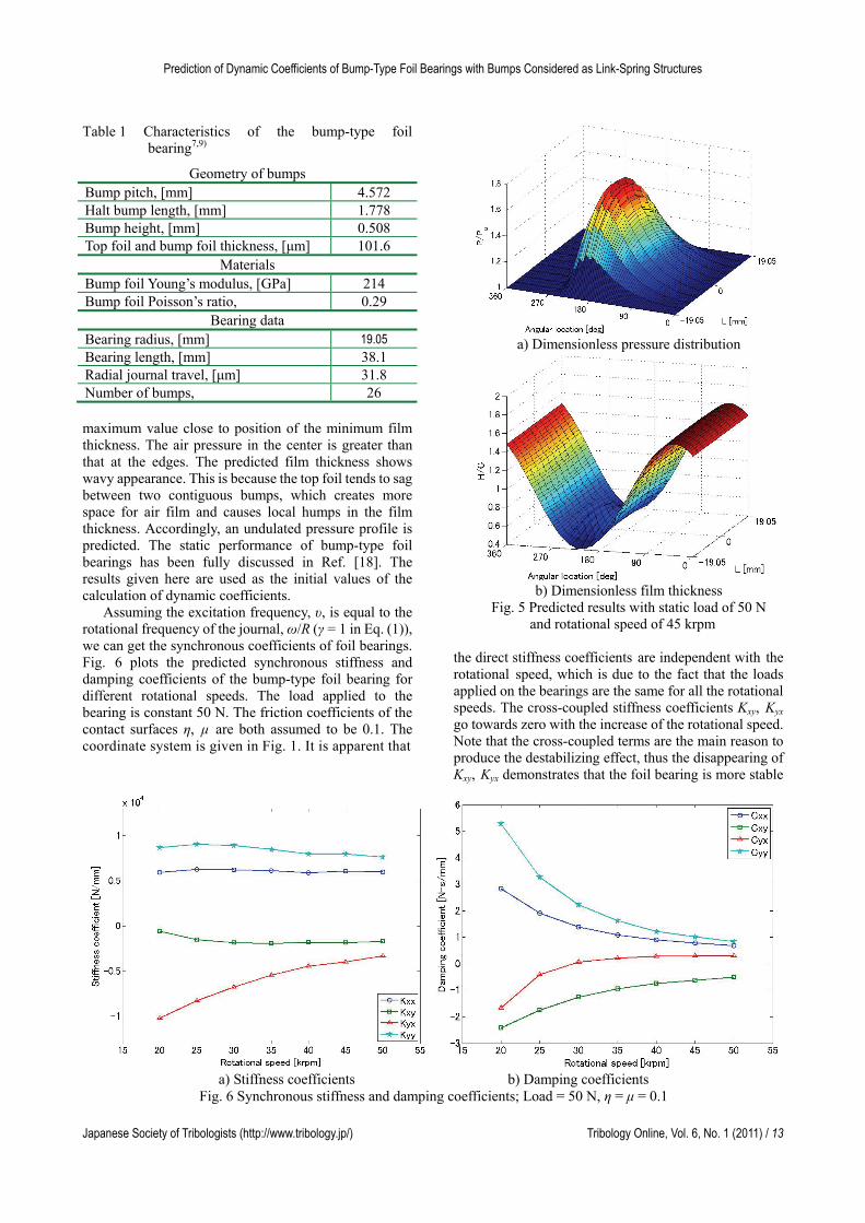
3.1. Prediction results of dynamic coefficients Fig. 5 presents the air pressure distribution and film
thickness at the equilibrium position with static load of 50 N and rotational speed of 45 krpm. These results is used as the initial air pressure, p0, and film thickness, h0, for the solution of Eqs. (8) and (9). It is noted that the obtained air pressure at the equilibrium position rise along the circumferential direction and reaches the
Japanese Society of Tribologists (http://www.tribology.jp/) Tribology Online, Vol. 6, No. 1 (2011) / 12
Prediction of Dynamic Coefficients of Bump-Type Foil Bearings with Bumps Considered as Link-Spring Structures
Table 1 Characteristics of the bump-type foil bearing7,9)
Geometry of bumps Bump pitch, [mm] 4.572 Halt bump length, [mm] 1.778 Bump height, [mm] 0.508 Top foil and bump foil thickness, [μm] 101.6
Materials Bump foil Young’s modulus, [GPa] 214 Bump foil Poisson’s ratio, 0.29
Bearing data Bearing radius, [mm] 19.05 Bearing length, [mm] 38.1 Radial journal travel, [μm] 31.8 Number of bumps, 26
a) Dimensionless pressure distribution
maximum value close to position of the minimum film thickness. The air pressure in the center is greater than that at the edges. The predicted film thickness shows wavy appearance. This is because the top foil tends to sag between two contiguous bumps, which creates more space for air film and causes local humps in the film thickness. Accordingly, an undulated pressure profile is predicted. The static performance of bump-type foil bearings has been fully discussed in Ref. [18]. The results given here are used as the initial values of the calculation of dynamic coefficients. b) Dimensionless film thickness
Fig. 5 Predicted results with static load of 50 N Assuming the excitation frequency, υ, is equal to the rotational frequency of the journal, ω/R (γ = 1 in Eq. (1)), we can get the synchronous coefficients of foil bearings. Fig. 6 plots the predicted synchronous stiffness and damping coefficients of the bump-type foil bearing for different rotational speeds. The load applied to the bearing is constant 50 N. The friction coefficients of the contact surfaces η, μ are both assumed to be 0.1. The coordinate system is given in Fig. 1. It is apparent that
and rotational speed of 45 krpm
the direct stiffness coefficients are independent with the rotational speed, which is due to the fact that the loads applied on the bearings are the same for all the rotational speeds. The cross-coupled stiffness coefficients Kxy, Kyx go towards zero with the increase of the rotational speed. Note that the cross-coupled terms are the main reason to produce the destabilizing effect, thus the disappearing of Kxy, Kyx demonstrates that the foil bearing is more stable
a) Stiffness coefficients b) Damping coefficients
Fig. 6 Synchronous stiffness and damping coefficients; Load = 50 N, η = μ = 0.1
Japanese Society of Tribologists (http://www.tribology.jp/) Tribology Online, Vol. 6, No. 1 (2011) / 13
Kai Feng and Shigehiko Kaneko
at higher rotation speed. Meanwhile, the direct stiffness coefficients Kyy are noted to be greater than Kxx, because y is the direction of bearing load. In Fig. 6b), the plots depict clear drops in magnitude of both the direct damping coefficients and the cross-coupled damping coefficients with the increase of speed. This is because at high rotational speeds (frequencies) the gas is compressed instead of being squeezed out of the bearing, which reduces the viscous damping of gas film8).
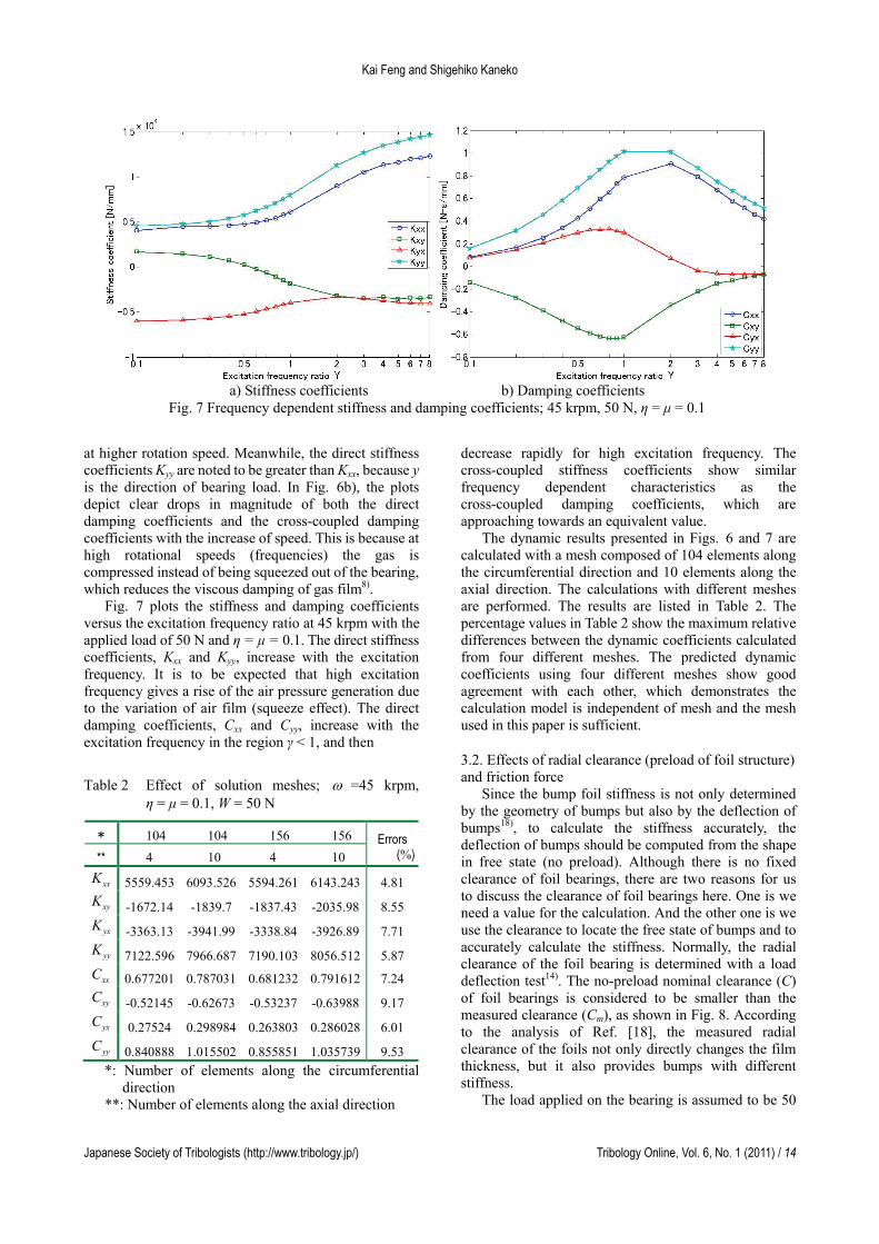
Fig. 7 plots the stiffness and damping coefficients versus the excitation frequency ratio at 45 krpm with the applied load of 50 N and η = μ = 0.1. The direct stiffness coefficients, Kxx and Kyy, increase with the excitation frequency. It is to be expected that high excitation frequency gives a rise of the air pressure generation due to the variation of air film (squeeze effect). The direct damping coefficients, Cxx and Cyy, increase with the excitation frequency in the region γ < 1, and then
Table 2 Effect of solution meshes; =45 krpm, η = μ = 0.1, W = 50 N
* 104 104 156 156
** 4 10 4 10 Errors
(%)
xxK 5559.453 6093.526 5594.261 6143.243 4.81
xyK -1672.14 -1839.7 -1837.43 -2035.98 8.55
yxK -3363.13 -3941.99 -3338.84 -3926.89 7.71
yyK 7122.596 7966.687 7190.103 8056.512 5.87
xxC 0.677201 0.787031 0.681232 0.791612 7.24
xyC -0.52145 -0.62673 -0.53237 -0.63988 9.17
yxC 0.27524 0.298984 0.263803 0.286028 6.01
yyC 0.840888 1.015502 0.855851 1.035739 9.53
*: Number of elements along the circumferential direction
**: Number of elements along the axial direction
decrease rapidly for high excitation frequency. The cross-coupled stiffness coefficients show similar frequency dependent characteristics as the cross-coupled damping coefficients, which are approaching towards an equivalent value.
a) Stiffness coefficients b) Damping coefficients
Fig. 7 Frequency dependent stiffness and damping coefficients; 45 krpm, 50 N, η = μ = 0.1
The dynamic results presented in Figs. 6 and 7 are calculated with a mesh composed of 104 elements along the circumferential direction and 10 elements along the axial direction. The calculations with different meshes are performed. The results are listed in Table 2. The percentage values in Table 2 show the maximum relative differences between the dynamic coefficients calculated from four different meshes. The predicted dynamic coefficients using four different meshes show good agreement with each other, which demonstrates the calculation model is independent of mesh and the mesh used in this paper is sufficient.
3.2. Effects of radial clearance (preload of foil structure) nd friction force a
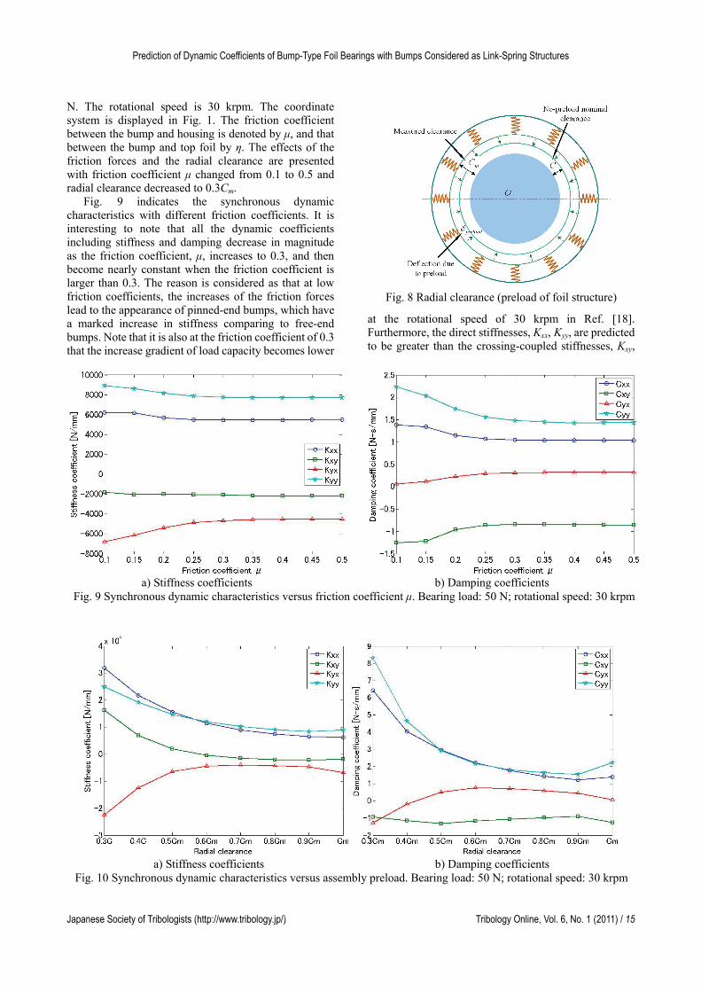
Since the bump foil stiffness is not only determined by the geometry of bumps but also by the deflection of bumps18), to calculate the stiffness accurately, the deflection of bumps should be computed from the shape in free state (no preload). Although there is no fixed clearance of foil bearings, there are two reasons for us to discuss the clearance of foil bearings here. One is we need a value for the calculation. And the other one is we use the clearance to locate the free state of bumps and to accurately calculate the stiffness. Normally, the radial clearance of the foil bearing is determined with a load deflection test14). The no-preload nominal clearance (C) of foil bearings is considered to be smaller than the measured clearance (Cm), as shown in Fig. 8. According to the analysis of Ref. [18], the measured radial clearance of the foils not only directly changes the film thickness, but it also provides bumps with different stiffness.
The load applied on the bearing is assumed to be 50
Japanese Society of Tribologists (http://www.tribology.jp/) Tribology Online, Vol. 6, No. 1 (2011) / 14
Prediction of Dynamic Coefficients of Bump-Type Foil Bearings with Bumps Considered as Link-Spring Structures
N. The rotational speed is 30 krpm. The coordinate system is displayed in Fig. 1. The friction coefficient between the bump and housing is denoted by μ, and that between the bump and top foil by η. The effects of the friction forces and the radial clearance are presented with friction coefficient μ changed from 0.1 to 0.5 and radial clearance decreased to 0.3Cm.
Fig. 9 indicates the synchronous dynamic characteristics with different friction coefficients. It is interesting to note that all the dynamic coefficients including stiffness and damping decrease in magnitude as the friction coefficient, μ, increases to 0.3, and then become nearly constant when the friction coefficient is larger than 0.3. The reason is considered as that at low friction coefficients, the increases of the friction forces lead to the appearance of pinned-end bumps, which have a marked increase in stiffness comparing to free-end bumps. Note that it is also at the friction coefficient of 0.3 that the increase gradient of load capacity becomes lower
at the rotational speed of 30 krpm in Ref. [18]. Furthermore, the direct stiffnesses, Kxx, Kyy, are predicted to be greater than the crossing-coupled stiffnesses, Kxy,
Fig. 8 Radial clearance (preload of foil structure)
a) Stiffness coefficients b) Damping coefficients
Fig. 9 Synchronous dynamic characteristics versus friction coefficient μ. Bearing load: 50 N; rotational speed: 30 krpm
a) Stiffness coefficients b) Damping coefficients
Fig. 10 Synchronous dynamic characteristics versus assembly preload. Bearing load: 50 N; rotational speed: 30 krpm
Japanese Society of Tribologists (http://www.tribology.jp/) Tribology Online, Vol. 6, No. 1 (2011) / 15
Kai Feng and Shigehiko Kaneko
Kyx. And the stiffness along the load direction Kyy is lager than Kxx,.
The effects of the radial clearance on the dynamic coefficients are demonstrated in Fig.10. It is apparent that all predictions of stiffness coefficients keep constant at high clearance, but increase dramatically in amount as the radial clearance decreases, when the radial clearance is less than 0.6Cm. The two direct components of damping, Cxx, Cyy, have similar variation, as shown in Fig. 10b). The cross-coupled damping coefficients, Cxy, Cyx, become negative as the radial clearance become smaller. The absolute value of Cyx increases. Note for that the cross-coupled terms, Kxy, Kyx, and the negative Cxy, Cyx are the reasons to produce destabilizing effect. This means that the foil bearing may be unstable when the radial clearance is lesser than 0.6Cm. It is necessary to be mentioned that the optimum radial clearance at 30 krpm are predicted to be 0.4Cm in Ref. [18], less than 0.6Cm. For foil bearings, the best assembly preload is not the one that can bring in largest load capacity, but the one that provide relatively larger load capacity and keep bearing stable. Therefore, the best assembly preload for the bump-type foil bearing given in this paper is predicted to be 0.6Cm.
The equivalent stiffness of bevel springs k2 in Fig. 4 can be obtained as
1
0 02 1 2 0 1 0 42 ( ) ( ) 2
2 2 2 2b bR R
k f f C fDL ES
(A2) where
22 2
1
2 2 22
2 2 2 23
4
5
32 sin 2 cos 2
2
4 cos sin 4 sin2 2 2 2
2 sin cos sin2 2 2 2
1sin 2
2cos sin
bb b
b b
b b
Rf R R
f R R
f R R R
f
f
2b
21
3 5
/
2 / 2 / 2 /
f DLC
f DL f SE
.
4. Conclusion
The theoretical model of bump-type foil bearings presented and validated in a previous study was used to describe the foil structure. An approach with the perturbation of the journal with respect to a small displacement about its equilibrium position was used for the prediction of dynamic coefficients of bump-type foil bearings.
The synchronous dynamic coefficients as well as the frequency dependent coefficients under a given bearing load were predicted. Solutions with different meshes were performed. The agreement results demonstrated the good accuracy of the model.
The dynamic coefficients of bump-type foil bearings with different friction coefficients and radical clearances were also presented. The radical clearance was noted to have a distinct influence on the instability of foil bearings. The critical radial clearance, from which the dynamic properties lead to the great increase of instability, was predicted to be larger than that producing the maximum load capacity18).
5. Appendix: Link-spring model
5.1. Stiffness of the elemental springs The horizontal equivalent stiffness in Fig.2 is
derived
1
13 2
00 0 0
0
sin 12 4 sin 2 sin 2
2 2
H
b b
Fk
R R
DL SE
5.2. Equivalent stiffness of bumps According to the force analysis at the segment
between two bumps, the equivalent vertical stiffness of the bump is expressed
1 112 i i i i
ViV i
L L k B kk
A
, (A3)
where
1 11
10.5 1
10.5 1
i i i i ii
i i i ii
A h tgtg
B h tgtg
1i
.
The equivalent vertical stiffness of the bump close to the free end can be written as
12N N
pNV N N
F L kk
h A
, (A4)
where
110.5 1N N N N
NA h tg
tg
0
N
.
The equivalent vertical stiffness of a pinned-end
bump is calculated as
2cos
spring springpV
L LFk
h h
, (A5)
where
22 2
cos2
spring b b
spring b
L R h
L R h
R.
(A1)
Japanese Society of Tribologists (http://www.tribology.jp/) Tribology Online, Vol. 6, No. 1 (2011) / 16
Prediction of Dynamic Coefficients of Bump-Type Foil Bearings with Bumps Considered as Link-Spring Structures
6. Nomenclature
iA iBFunctions defined by Eqs.(10) and (11)
C No-preload nominal clearance
mC Measured radial clearance D Bearing diameter E Bump foils Young’s modulus
,x yF F Bearing forces ipF Load applied on the ith bump i
sF Horizontal spring force i
beamF Force of the link.
h Film thickness
bh Bump height
h Deflection of foils
midH Minimum mid plane film thickness
edgeH Minimum edge film thickness
minH Minimum film thickness
1 2,k k Stiffness of spring
iVk Equivalent vertical stiffness of
bumps
mmK , mmC Stiffness coefficients and damping coefficients
L Foil width/length of the bearing
1L Length of links
springL , springL Length of spring
L Deformation of spring
blp
Half bump length Air pressure
ap Ambient pressure R Bearing radius
bR Bump radius r Shaft radius
0s Bump pitch t Time
ft Foil thickness W Bearing load
,x y Journal position perturbations
,x y Journal velocity perturbations
α, Angle of rigid link
, z Foil deflection
pre Top foil deflection with preload Eccentricity ratio , Friction coefficient
0 Viscosity of air Bump foil Poisson’s ratio
0 Half bump angle
min Angular position of minH Excitation frequency
Journal angular velocity Excitation frequency ratio Superscripts i Variables of the ith bump
Dimensionless variables Subscripts
V Variables in vertical direction
b Variables of a bump
0 Variables in the equilibrium position, z Axial and angular coordinate ,x y Horizontal and vertical coordinate
7. References
[1] Heshmat, H., Hryniewicz, P., Walton, J. F., Willis, J. P., Jahanmir, S. and DellaCorte, C., “Low-Friction Wear-Resistant Coatings for High-Temperature Foil Bearings,” Tribology International, 38, 2005, 1059-1075.
[2] Agrawal, G. L., “Foil Air/Gas Bearing Technology - An Overview,” ASME Paper No. 97-GT-347, 1997.
[3] DellaCorte, C. and Valco, M. J., “Load Capacity Estimation of Foil Air Journal Bearings for Oil-Free Turbomachinery Applications,” NASA/TM, Report No. 2000-209782, 2000.
[4] Salehi, M., Heshmat, H., Walton, J. F. and Tomaszewski, M., “Operation of a Mesoscopic Gas Turbine Simulator at Speeds in Excess of 700,000 rpm on Foil Bearings,” Trans. ASME, Journal of Tribology, 129, 2007, 170-176.
[5] Heshmat, H., Walowit, J. A. and Pinkus, O., “Analysis of Gas Lubricated Foil Journal Bearings,” Trans. ASME, Journal of Lubrication Technology, 105, 1983, 647-655.
[6] Iordanoff, I., “Analysis of an Aerodynamic Compliant Foil Thrust Bearing: Method for a Rapid Design,” Trans. ASME, Journal of Tribology, 121, 1999, 816-822.
[7] San Andres, L. and Kim, T. H., “Improvements to the Analysis of Gas Foil Bearings: Integration of Top Foil 1D and 2D Structural Models,” ASME Paper No. GT2007-27249, 2007.
[8] Carpino, M. and Talmage, G., “Prediction of Rotor Dynamic Coefficients in Gas Lubricated Foil Journal Bearings with Corrugated Sub-Foils,” Tribology Transactions, 49, 2006, 400-409.
[9] Le Lez, S., Arghir, M. and Frene J., “A New Bump-Type Foil Bearing Structure Analytical Model,” Trans. ASME, Journal of Engineering for Gas Turbines and Power, 129, 2007, 1047-1057.
[10] Ku, C. P. and Heshmat, H., “Compliant Foil Bearing Structure Stiffness Analysis: Part I - Theoretical Model Including Strip and Variable Bump Foil Geometry,” Trans. ASME, Journal of Tribology, 114, 1992, 394-400.
[11] Ku, C. P. and Heshmat, H., “Compliant Foil
Japanese Society of Tribologists (http://www.tribology.jp/) Tribology Online, Vol. 6, No. 1 (2011) / 17
Kai Feng and Shigehiko Kaneko
Japanese Society of Tribologists (http://www.tribology.jp/) Tribology Online, Vol. 6, No. 1 (2011) / 18
Bearing Structural Stiffness Analysis: Part II - Experimental Investigation,” Trans. ASME, Journal of Tribology, 115, 1993, 364-369.
[12] Ku, C. P. and Heshmat, H., “Structure Stiffness and Coulomb Damping in Compliant Foil Journal Bearings: Theoretical Considerations,” Tribology Transactions, 37, 1994, 525-533.
[13] Ku, C. P. and Heshmat, H., “Structural Stiffness and Coulomb Damping in Compliant Foil Journal Bearings: Parametric Studies,” Tribology Transactions, 37, 1994, 455-462.
[14] Radil, K., Howard, S. and Dykas, B., “The Role of Radial Clearance on the Performance of Foil Air Bearing,” NASA-2002-211705, 2002.
[15] Kim, T. H. and San Andres, L., “Heavily Loaded
Gas Foil Bearings: A Model Anchored to Test Data,” Trans. ASME, Journal of Engineering for Gas Turbines and Power, 130, 2008, 012504.
[16] Kim, T. H. and San Andres, L., “Limits for High-Speed Operation of Gas Foil Bearings,” Trans. ASME, Journal of Tribology, 128, 2006, 670-673.
[17] Peng, J. P. and Carpino, M., “Calculation of Stiffness and Damping Coefficients for Elastically Supported Gas Foil Bearings,” Trans. ASME, Journal of Tribology, 115, 1993, 20-27.
[18] Feng, K. and Kaneko, S., “Link-Spring Model of Bump-Type Foil Bearing,” ASME Paper No. GT2009-59260, 2009.