Embed Size (px)
Citation preview
Pulse Splitting in Short Wavelength Seeded Free Electron Lasers
M. Labat,1,* N. Joly,2,3 S. Bielawski,2 C. Szwaj,2 C. Bruni,4 and M. E. Couprie1
1Synchrotron SOLEIL, Saint Aubin, BP 34, 91 192 Gif-sur-Yvette, France2Laboratoire des Physique des Lasers, Atomes et Molecules, UMR CNRS 8523, Centre d’Etudes et de Recherches Lasers etApplications, FR CNRS 2416, Universite des Sciences et Technologies de Lille, F-59655 Villeneuve d’Asq Cedex, France
3University of Erlangen-Nuremberg, Guenther-Scharowsky Strasse 1/bau 24, 91058 Erlangen, Germany4LAL, Universite Paris-Sud 11, UMR 8607, batiment 200, 91898 Orsay Cedex, France
(Received 24 September 2009; published 23 December 2009)
We investigate a fundamental limitation occurring in vacuum ultraviolet and extreme ultraviolet seeded
free electron lasers (FELs). For a given electron beam and undulator configuration, an increase of the FEL
output energy at saturation can be obtained via an increase of the seed pulse duration. We put in evidence a
complex spatiotemporal deformation of the amplified pulse, leading ultimately to a pulse splitting effect.
Numerical studies of the Colson–Bonifacio FEL equations reveal that slippage length and seed laser pulse
wings are core ingredients of the dynamics.
DOI: 10.1103/PhysRevLett.103.264801 PACS numbers: 41.60.Cr, 42.65.Ky
Short duration, short wavelength, and high power elec-tromagnetic radiation enables the investigation of ultrafastphenomena at the atomic scale. Nowadays, x-ray sourcescan be provided by synchrotron light sources [1], harmonicgeneration in gas [2], and on solid targets [3,4] or Thomsonscattering [5], for example. One of the most powerful andpromising devices is the single pass free electron laser(FEL) [6,7]. In a FEL system, a relativistic electron beamwiggles on an oscillating trajectory forced by the periodicmagnetic field of an undulator, and interacts with opticalradiation which can be provided either by the electronbeam spontaneous emission [6] or a coherent externalsource [8] referred as a seed. The seeded FEL offers thehighest temporal coherence. In such a system, the dynami-cal regime determines output radiation pulse character-istics [9]. For instance, in the steady-state regime, the
FEL power saturates after scaling as z4=3, with z thedistance in the undulator, while in the superradiant regime[10–12], the FEL power does not saturate and scales as z2.
In this Letter, we theoretically evidence a new spatio-temporal regime, for which the emitted FEL pulse splitsinto two subpulses. This dynamical behavior occurs inseeded FEL with long seed pulse duration and may berelevant for the next generation short wavelength seededFELs such as ARC-EN-CIEL [13], FERMI [14], andSPARX [15]. The understanding and control of these re-gimes is essential for the optimization of the FEL sourcesin terms of output power and optical quality since both aredemanded by users communities. Using the Colson-Bonifacio model [6,16], we evidence the behaviors of theseeded FEL and provide further insight on the pulse split-ted regime, which is interpreted in terms of gain saturation.
The radiation amplification mechanism in FELs is com-monly analyzed in three steps [7]: energy modulation (alsoreferred as lethargy [6]), exponential growth, and satura-tion. During the first evolution step, i.e., along the first
periods of the undulator, energy exchange is performedbetween the electrons and the radiation, leading to anenergy modulation and further to a density modulation(microbunching) of the electrons at the resonant wave-
length �R ¼ �0
2�2 ð1þ K2=2Þ. �R is fixed by the electron
beam normalized energy � and the undulator period �0
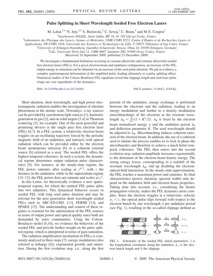
and deflection parameter K. The seed wavelength shouldbe adjusted to �R. Microbunching induces coherent emis-sion of the electron beam. In addition, the use of a coherentseed to initiate the process enables us to lock in phase themicrobunches and therefore to achieve a much better tem-poral coherence. The FEL then enters into the secondevolution step: radiation amplitude increases exponentiallyto the detriment of the electron beam kinetic energy. Thestrong energy losses, corresponding to a redshift of theresonant wavelength �R, end up disabling the electron-optical field interaction. In the steady-state approximation,the FEL reaches a maximum power and saturates. Its finalcharacteristics (power, duration, spectral width) only de-pend on the undulator field and electron beam properties.Taking time into account, i.e., considering the beamspropagation velocity, makes the FEL dynamics more com-plex. Since the electron wiggles at a relativistic velocityvz < c, the optical pulse slips forward with respect to theelectron bunch by one wavelength � per undulator period(see Fig. 1), resulting in the so-called slippage defined as
FIG. 1. Schematic of the seeded FEL initial parameters. �z isthe longitudinal coordinate along the undulator. Le is the elec-tron bunch length and � the slippage.
PRL 103, 264801 (2009) P HY S I CA L R EV I EW LE T T E R Sweek ending
31 DECEMBER 2009
0031-9007=09=103(26)=264801(4) 264801-1 � 2009 The American Physical Society
� ¼ N�, i.e., the displacement of the optical pulse withrespect to the electron beam at the end of the N periods ofthe undulator. The present quest of compact and shortwavelength devices tends to reduce it. The possible slip-page configurations are represented schematically inFig. 1. In (a), a short seed pulse with respect to the bunchlength is injected and slips within the undulator distanceover the whole electron bunch. In (b), the slippage isshorter than the electron bunch length, which limits theinteraction region. This is the operating area of severalexisting FELs, such as SCSS test accelerator [17],SPARC [18,19], and sFLASH [20]. We will see that usinga longer seed pulse [case (c)] enables us to increase theinteraction region but also eventually leads to complexspatiotemporal deformation of the optical pulse such aspulse splitting.
In universal scaling [9], the FEL dynamics can be de-scribed by the one-dimensional Colson-Bonifacio [6,16]model:
@�j
@�z¼ pj; (1a)
@pj
@�z¼ �½Að �z; �Þei�j þ c:c:�; (1b)
�@
@�zþ @
@�
�Að�z; �Þ ¼ �ð�Þbð�z; �Þ: (1c)
Each particle j, j ¼ 1 . . .Ne with Ne the total number ofelectrons, in the optical field A, is followed in the phasespace using �j, the particle relative phase, and pj, the
particle relative energy both normalized to the referenceparticle. The variables �j, pj, and A are functions of the
longitudinal coordinates � along the electron bunch and �zalong the undulator. � is defined within 0< �< Le, withLe the electron bunch length, and �z is defined within 0<�z < Lu, with Lu the undulator length. All dimensions are incooperation length [10,21] units: lc ¼ �
4�� , with � the
Pierce fundamental scaling parameter [6] characterizingthe gain of the FEL. � is the macroscopic electronicdensity normalized to 1 and bð�z; �Þ is the bunching coeffi-cient: bð�z; �Þ ¼ 1=Ne
Pe�i�j . Equations (1a) and (1b)
describe the particle dynamics while Eq. (1c) includesthe pulse propagation.
The initial conditions required for the various regimescan be defined more precisely using Se comparing theslippage length to the electron bunch length, and Sseedcomparing the slippage length to the seed pulse duration.In the scaled units, with Lseed the seed pulse duration, theslippage length corresponds to the final �z ¼ 4��N, so that
Se ¼ 4��N
Le
and Sseed ¼ 4��N
Lseed
: (2)
In the short electron bunch limit, i.e., Se � 1, the FELevolves in the weak superradiant regime [10]: the strong
slippage enables the development of a narrow spike in theleading edge of the electron bunch which rapidly escapesof the electron bunch. Because of the limited interactiontime, the final output power remains lower than the satu-ration power defined in the steady-state approximation. Inthe present seeded FEL context, Se tends to decrease viathe reduction of �R for the short wavelength operation andof N for the shortening of the undulators. SPARC [18](Se � 0:2) and SCSS test accelerator [17] (Se � 0:3)seeded FELs already fall in the Se < 1 area, illustrated inFigs. 1(b) and 1(c).The FEL evolution is simulated with Eq. (1) in the long
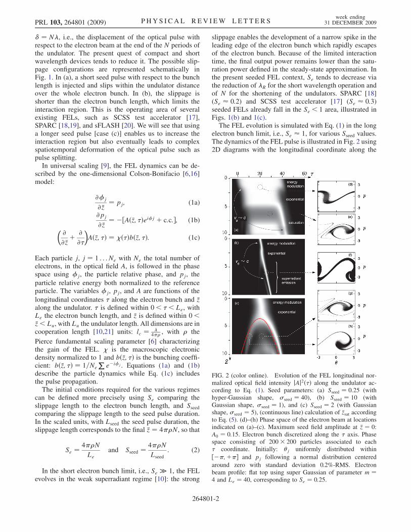
electron bunch limit, i.e., Se � 1, for various Sseed values.The dynamics of the FEL pulse is illustrated in Fig. 2 using2D diagrams with the longitudinal coordinate along the
FIG. 2 (color online). Evolution of the FEL longitudinal nor-malized optical field intensity jAj2ð�Þ along the undulator ac-cording to Eq. (1). Seed parameters: (a) Sseed ¼ 0:25 (withhyper-Gaussian shape, seed ¼ 40), (b) Sseed ¼ 10 (withGaussian shape, seed ¼ 1), and (c) Sseed ¼ 2 (with Gaussianshape, seed ¼ 5), (continuous line) calculation of �zsat accordingto Eq. (5). (d)–(h) Phase space of the electron beam at locationsindicated on (a)–(c). Maximum seed field amplitude at �z ¼ 0:A0 ¼ 0:15. Electron bunch discretized along the � axis. Phasespace consisting of 200� 200 particles associated to each� coordinate. Initially: j uniformly distributed within
½��;þ�� and pj following a normal distribution centered
around zero with standard deviation 0.2%-RMS. Electronbeam profile: flat top using super Gaussian of parameter m ¼4 and Le ¼ 40, corresponding to Se ¼ 0:25.
PRL 103, 264801 (2009) P HY S I CA L R EV I EW LE T T E R Sweek ending
31 DECEMBER 2009
264801-2
electron bunch � in the horizontal axis and the coordinatealong the undulator �z in the vertical axis. Figure 2(a), withSseed < 1, represents the standard evolution of the seededFEL which can be also obtained in the steady-state model[9]. The seed electric field first performs energy modula-tion of the electron bunch and slips along the electronbunch at a speed vg close to the light velocity. Along the
undulator, the energy modulation is converted into a den-sity modulation and the particles rotate in the phase space[see Fig. 2(d)]. The optical field is then exponentiallyamplified to the detriment of the particles kinetic energyand slows down by the electronic medium (vg < c). At the
end of the exponential growth (�z � 4), the FEL saturatesand the optical pulse no longer interacts with electrons andslips ahead of the bunch at the light velocity. A typicalsaturated phase space is presented in Fig. 2(e). For Sseed >1 [see Fig. 2(b)], the FEL evolves into the strong super-radiant regime [10–12]. At the end of the exponentialgrowth, the optical pulse slips as in the exponential regimeahead of the electron bunch at the light velocity but nolonger saturates [see Fig. 2(f)]. Considering typical designsof compact facilities in the vuv range with N � 500 and�R � 10 nm, the range Sseed > 1 corresponds to a 1 fs seedpulse duration, which can be only achieved to the detrimentof the charge [22]. In the case of Fig. 2(c), Sseed � 1 andthe development of two subpulses at the output of theexponential growth is clearly visible. At a given positionin the undulator shortly after the pulse splitting location,the particle distribution in the phase space is much stronglyover modulated where the splitting occurred [Fig. 2(g)]than on the tail [Fig. 2(h)]. Since overmodulation is asignature of local saturation, the bunch slices initiallyunder the center of the seed distribution, modulated withhigher optical field, reach saturation within a shorterdistance in the undulator than edges slices modulatedwith the lower optical power of the seed wings. Thisdelayed arrival to saturation is responsible for the genera-tion of two pulses on the edges. Since the electrons carry ontheir rotation in the phase space within the optical pulseelectric field, the process repeats after one cycle: additionalsubpulses, still generated at the center of the distribution,appear further down in the undulator. These pulses remainat a weak intensity since most of the available electronskinetic energy has already been transferred to the first twosubpulses.
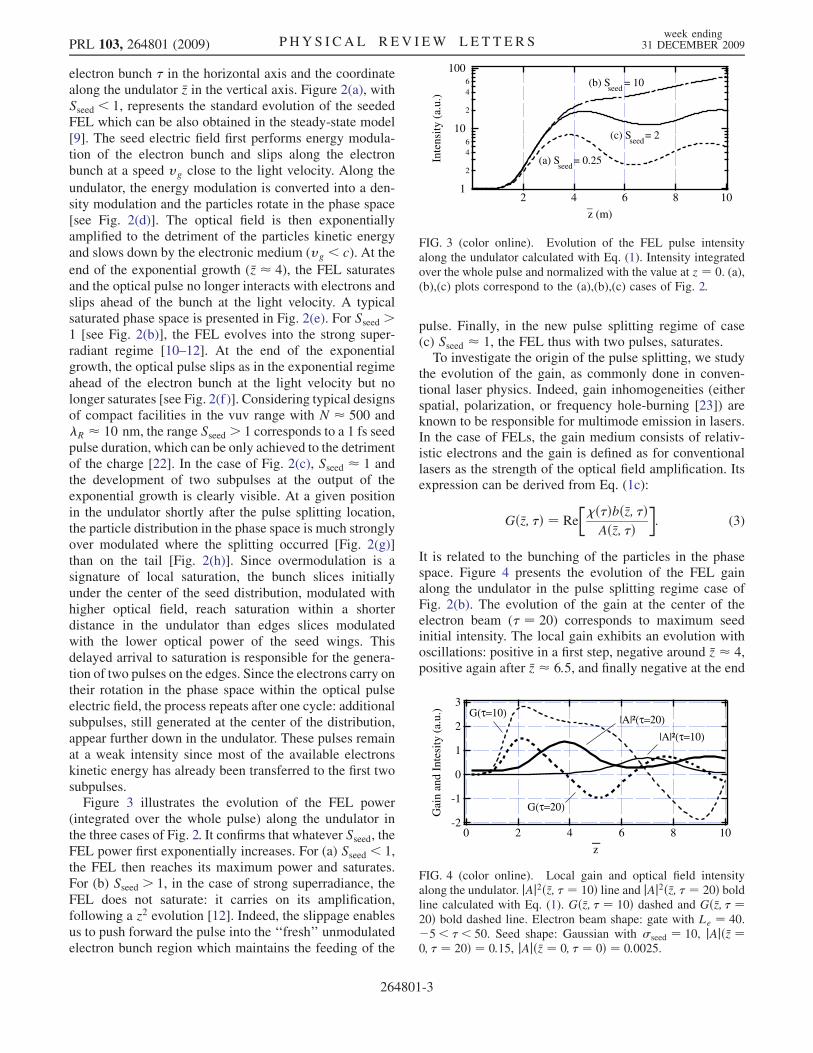
Figure 3 illustrates the evolution of the FEL power(integrated over the whole pulse) along the undulator inthe three cases of Fig. 2. It confirms that whatever Sseed, theFEL power first exponentially increases. For (a) Sseed < 1,the FEL then reaches its maximum power and saturates.For (b) Sseed > 1, in the case of strong superradiance, theFEL does not saturate: it carries on its amplification,following a z2 evolution [12]. Indeed, the slippage enablesus to push forward the pulse into the ‘‘fresh’’ unmodulatedelectron bunch region which maintains the feeding of the
pulse. Finally, in the new pulse splitting regime of case(c) Sseed � 1, the FEL thus with two pulses, saturates.To investigate the origin of the pulse splitting, we study
the evolution of the gain, as commonly done in conven-tional laser physics. Indeed, gain inhomogeneities (eitherspatial, polarization, or frequency hole-burning [23]) areknown to be responsible for multimode emission in lasers.In the case of FELs, the gain medium consists of relativ-istic electrons and the gain is defined as for conventionallasers as the strength of the optical field amplification. Itsexpression can be derived from Eq. (1c):
Gð�z; �Þ ¼ Re
��ð�Þbð�z; �ÞAð�z; �Þ
�: (3)
It is related to the bunching of the particles in the phasespace. Figure 4 presents the evolution of the FEL gainalong the undulator in the pulse splitting regime case ofFig. 2(b). The evolution of the gain at the center of theelectron beam (� ¼ 20) corresponds to maximum seedinitial intensity. The local gain exhibits an evolution withoscillations: positive in a first step, negative around �z � 4,positive again after �z � 6:5, and finally negative at the end
1
2
46
10
2
46
100
Inte
nsit
y (a
.u.)
108642
z (m)_
(a) S = 0.25seed
(b) S = 10seed
(c) S = 2seed
FIG. 3 (color online). Evolution of the FEL pulse intensityalong the undulator calculated with Eq. (1). Intensity integratedover the whole pulse and normalized with the value at z ¼ 0. (a),(b),(c) plots correspond to the (a),(b),(c) cases of Fig. 2.
3
2
1
0
-1
-2
Gai
n an
d In
tesi
ty (
a.u.
)
1086420
z_
G(τ=10)
G(τ=20)
|A|²(τ=20)|A|²(τ=10)
FIG. 4 (color online). Local gain and optical field intensityalong the undulator. jAj2ð�z; � ¼ 10Þ line and jAj2ð�z; � ¼ 20Þ boldline calculated with Eq. (1). Gð�z; � ¼ 10Þ dashed and Gð�z; � ¼20Þ bold dashed line. Electron beam shape: gate with Le ¼ 40.�5< �< 50. Seed shape: Gaussian with seed ¼ 10, jAjð�z ¼0; � ¼ 20Þ ¼ 0:15, jAjð�z ¼ 0; � ¼ 0Þ ¼ 0:0025.
PRL 103, 264801 (2009) P HY S I CA L R EV I EW LE T T E R Sweek ending
31 DECEMBER 2009
264801-3
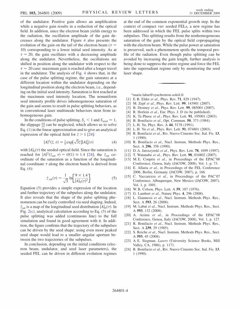
of the undulator. Positive gain allows an amplificationwhile a negative gain results in a reduction of the opticalfield. In addition, since the electron beam yields energy tothe radiation, the oscillation amplitude of the gain de-creases along the undulator. Figure 4 also presents theevolution of the gain on the tail of the electron beam (� ¼10) corresponding to a lower initial seed intensity. As at� ¼ 20, the gain oscillates with a decreasing amplitudealong the undulator. Nevertheless, the oscillations areshifted in position along the undulator with respect to the� ¼ 20 case: maximum gain is reached after a longer travelin the undulator. The analysis of Fig. 4 shows that, in thecase of the pulse splitting regime, the gain saturates at adifferent location within the undulator depending on thelongitudinal position along the electron beam, i.e., depend-ing on the initial seed intensity. Saturation is first reached atthe maximum seed intensity location. The nonuniformseed intensity profile drives inhomogeneous saturation ofthe gain and seems to result in pulse splitting behaviors, asin conventional laser multimode behaviors stem from in-homogeneous gain.
In the conditions of pulse splitting, Se < 1 and Sseed � 1,the slippage @A
@� can be neglected, which allows us to solve
Eq. (1) in the linear approximation and to give an analyticalexpression of the optical field for �z > 1 [24]:
jAj2ð�z; �Þ � 19 exp½
ffiffiffi3
p�z�jAj20ð�Þ (4)
with jAj0ð�Þ the seeded optical field. Since the saturation isreached for jAj2ð�zsat; �Þ ¼ Oð1Þ ffi 1:4 [24], the �zsat co-ordinate of the saturation as a function of the longitudi-nal coordinate � along the electron bunch is derived fromEq. (4):
�z satð�Þ ¼ 1ffiffiffi3
p ln
�9� 1:4
jAj0ð�Þ2�: (5)
Equation (5) provides a simple expression of the locationand further trajectory of the subpulses along the undulator.It also reveals that the shape of the pulse splitting phe-nomenon can be easily controlled via seed shaping. Indeed,�zsat is a map of the longitudinal seed distribution jAj0ð�Þ. InFig. 2(c), analytical calculation according to Eq. (5) of thepulse splitting was added (continuous line) to the fullsimulation and found in good agreement with it. In addi-tion, the figure confirms that the trajectory of the subpulsescan be driven by the seed shape: using even more peakedseed shape would lead to a smaller angular aperture be-tween the two trajectories of the subpulses.
In conclusion, depending on the initial conditions (elec-tron beam, undulator, and seed laser parameters), theseeded FEL can be driven in different evolution regimes
at the end of the common exponential growth step. In thecontext of compact vuv seeded FELs, a new regime hasbeen addressed in which the FEL pulse splits within twosubpulses. This splitting results from the nonhomogeneoussaturation of the gain by the optical field copropagatingwith the electron beam.While the pulse power at saturationis preserved, such a phenomenon spoils the temporal pro-file of the radiation. Even though pulse splitting can beavoided by increasing the gain length, further analysis isbeing done to suppress the entire regime and force the FELinto the superradiant regime only by monitoring the seedlaser shape.
*[email protected][1] E. R. Elder et al., Phys. Rev. 71, 829 (1947).[2] M. Zepf et al., Phys. Rev. Lett. 99, 143901 (2007).[3] B. Dromey et al., Phys. Rev. Lett. 99, 085001 (2007).[4] R. Horlein et al., Eur. Phys. J. D (to be published).[5] K. Ta Phuoc et al., Phys. Rev. Lett. 91, 195001 (2003).[6] B. Bonifacio et al., Opt. Commun. 50, 373 (1984).[7] L. H. Yu, Phys. Rev. A 44, 5178 (1991).[8] L. H. Yu et al., Phys. Rev. Lett. 91, 074801 (2003).[9] R. Bonifacio et al., Riv. Nuovo Cimento Soc. Ital. Fis. 13,
1 (1990).[10] R. Bonifacio et al., Nucl. Instrum. Methods Phys. Res.,
Sect. A 296, 358 (1990).[11] D. A. Jaroszynski et al., Phys. Rev. Lett. 78, 1699 (1997).[12] T. Watanabe et al., Phys. Rev. Lett. 98, 034802 (2007).[13] M. E. Couprie et al., in Proceedings of the EPAC’08
Conference, Genoa, Italy (JACOW, 2008), Vol. 1, p. 73.[14] E. Allaria et al., in Proceedings of the FEL Conference
2006, Berlin, Germany (JACOW, 2007), p. 166.[15] C. Vaccarezza et al., in Proceedings of the PAC’07
Conference, Albuquerque, New Mexico (JACOW, 2007),Vol. 1, p. 1001.
[16] W.B. Colson, Phys. Lett. A 59, 187 (1976).[17] G. Lambert et al., Nature Phys. 4, 296 (2008).[18] L. Giannessi et al., Nucl. Instrum. Methods Phys. Res.,
Sect. A 593, 26 (2008).[19] M. Labat et al., Nucl. Instrum. Methods Phys. Res., Sect.
A 593, 132 (2008).[20] A. Azima et al., in Proceedings of the EPAC’08
Conference, Genoa, Italy (JACOW, 2008), Vol. 1, p. 127.[21] R. Bonifacio et al., Nucl. Instrum. Methods Phys. Res.,
Sect. A 239, 29 (1985).[22] S. Reiche et al., Nucl. Instrum. Methods Phys. Res., Sect.
A 593, 45 (2008).[23] A. E. Siegman, Lasers (University Science Books, Mill
Valley, CA, 1986), p. 1171.[24] R. Bonifacio et al., Riv. Nuovo Cimento Soc. Ital. Fis. 13,
1 (1990).
PRL 103, 264801 (2009) P HY S I CA L R EV I EW LE T T E R Sweek ending
31 DECEMBER 2009
264801-4