Embed Size (px)
Citation preview
i
Université de Montréal
Reliable Message Dissemination in Mobile Vehicular
Networks
par
Benrhaiem Wiem
Département d’informatique et de recherche opérationnelle
Faculté des arts et des sciences
Thèse présentée Thèse présentée à la Faculté des études supérieures
en vue de l’obtention du grade de Philosophiæ Doctor (Ph.D.)
en computer science
Avril, 2017
© Benrhaiem Wiem, 2017
ii
Résumé
Les réseaux véhiculaires accueillent une multitude d’applications d’info-divertissement et de
sécurité. Les applications de sécurité visent à améliorer la sécurité sur les routes (éviter les
accidents), tandis que les applications d’info-divertissement visent à améliorer l'expérience des
passagers. Les applications de sécurité ont des exigences rigides en termes de délais et de
fiabilité ; en effet, la diffusion des messages d’urgence (envoyés par un véhicule/émetteur)
devrait être fiable et rapide. Notons que, pour diffuser des informations sur une zone de taille
plus grande que celle couverte par la portée de transmission d’un émetteur, il est nécessaire
d’utiliser un mécanisme de transmission multi-sauts. De nombreuses approches ont été proposées
pour assurer la fiabilité et le délai des dites applications. Toutefois, ces méthodes présentent
plusieurs lacunes.
Cette thèse, nous proposons trois contributions. La première contribution aborde la question
de la diffusion fiable des messages d’urgence. A cet égard, un nouveau schéma, appelé REMD,
a été proposé. Ce schéma utilise la répétition de message pour offrir une fiabilité garantie, à
chaque saut, tout en assurant un court délai. REMD calcule un nombre optimal de répétitions en
se basant sur l’estimation de la qualité de réception de lien dans plusieurs locations (appelées
cellules) à l’intérieur de la zone couverte par la portée de transmission de l’émetteur. REMD
suppose que les qualités de réception de lien des cellules adjacentes sont indépendantes. Il
sélectionne, également, un nombre de véhicules, appelés relais, qui coopèrent dans le contexte
de la répétition du message d’urgence pour assurer la fiabilité en multi-sauts. La deuxième
contribution, appelée BCRB, vise à améliorer REMD ; elle suppose que les qualités de réception
de lien des cellules adjacentes sont dépendantes ce qui est, généralement, plus réaliste. BCRB
utilise les réseaux Bayésiens pour modéliser les dépendances en vue d’estimer la qualité du lien
de réception avec une meilleure précision. La troisième contribution, appelée RICS, offre un
accès fiable à Internet. RICS propose un modèle d’optimisation, avec une résolution exacte
optimale à l'aide d’une technique de réduction de la dimension spatiale, pour le déploiement des
passerelles. Chaque passerelle utilise BCRB pour établir une communication fiable avec les
véhicules.
Mots clés: messages d’urgence, Internet des véhicules, fiabilité, diffusion, multi-sauts.
iii
Abstract
Vehicular networks aim to enable a plethora of safety and infotainment applications. Safety
applications aim to preserve people's lives (e.g., by helping in avoiding crashes) while
infotainment applications focus on enhancing the passengers’ experience. These applications,
especially safety applications, have stringent requirements in terms of reliability and delay;
indeed, dissemination of an emergency message (e.g., by a vehicle/sender involved in a crash)
should be reliable while satisfying short delay requirements. Note, that multi-hop dissemination
is needed to reach all vehicles, in the target area, that may be outside the transmission range of
the sender. Several schemes have been proposed to provide reliability and short delay for
vehicular applications. However, these schemes have several limitations. Thus, the design of new
solutions, to meet the requirement of vehicular applications in terms of reliability while keeping
low end-to-end delay, is required.
In this thesis, we propose three schemes. The first scheme is a multi-hop reliable emergency
message dissemination scheme, called REMD, which guarantees a predefined reliability , using
message repetitions/retransmissions, while satisfying short delay requirements. It computes an
optimal number of repetitions based on the estimation of link reception quality at different
locations (called cells) in the transmission range of the sender; REMD assumes that link reception
qualities of adjacent cells are independent. It also adequately selects a number of vehicles, called
forwarders, that cooperate in repeating the emergency message with the objective to satisfy
multi-hop reliability requirements. The second scheme, called BCRB, overcomes the
shortcoming of REMD by assuming that link reception qualities of adjacent cells are dependent
which is more realistic in real-life scenarios. BCRB makes use of Bayesian networks to model
these dependencies; this allows for more accurate estimation of link reception qualities leading
to better performance of BCRB. The third scheme, called RICS, provides internet access to
vehicles by establishing multi-hop reliable paths to gateways. In RICS, the gateway placement
is modeled as a k-center optimisation problem. A space dimension reduction technique is used
to solve the problem in exact time. Each gateway makes use of BCRB to establish reliable
communication paths to vehicles.
Key words: emergency message dissemination, Internet of Vehicles, Reliability, broadcast,
multi-hop.
iv
Contents
Chapter 1 Introduction ......................................................................................................................... 14
1.1. Introduction ................................................................................................................................... 14
1.2. Vehicular Ad Hoc Networks ......................................................................................................... 16
1.2.1. V2V and V2I communication modes ..................................................................................... 16
1.2.2. DSRC Overview ..................................................................................................................... 17
1.2.3. VANET characteristics ........................................................................................................... 20
1.2.4. VANET Applications ............................................................................................................. 23
1.3. Motivations and Problem statement .............................................................................................. 29
1.4. Thesis Contributions...................................................................................................................... 34
1.5. Thesis Organization ....................................................................................................................... 36
Chapter 2 Related work ....................................................................................................................... 37
2.1. Introduction ................................................................................................................................... 37
2.2. Flooding ........................................................................................................................................ 37
2.3. Broadcasting challenges in urban environment ............................................................................. 38
2.4. Emergency message dissemination ............................................................................................... 39
2.4.1. CSMA-based multi-hop broadcast ......................................................................................... 39
2.4.2. Limitations of CSMA-based multi-hop broadcast schemes ................................................... 44
2.4.3. Repetition-based Broadcast schemes ..................................................................................... 45
2.4.4. Limitations of repetition-based MAC schemes ...................................................................... 47
2.4.5. Summary of emergency message dissemination schemes ................................................... 47
2.5. Internet Gateway Discovery .......................................................................................................... 49
2.5.1. Proactive approaches .............................................................................................................. 49
2.5.2. Reactive approaches ............................................................................................................... 50
2.5.3. Hybrid approaches .................................................................................................................. 51
2.5.4 Limitations of Internet gateway discovery schemes ................................................................ 51
2.6. Conclusion ..................................................................................................................................... 53
Chapter 3 Reliable Emergency Message Dissemination for Urban Vehicular Networks ... 54
Abstract ................................................................................................................................................ 54
3.1. Introduction ................................................................................................................................... 55
v
3.2. Related work and Motivation ........................................................................................................ 58
3.3. REMD: An Overview .................................................................................................................... 64
3.4. Initialization Phase: IN .................................................................................................................. 67
3.5. Data Collection: DC ...................................................................................................................... 68
3.6. Local State Processing: LSP .......................................................................................................... 70
3.7. Broadcast Reliability: BR .............................................................................................................. 72
3.8. Forwarders selection...................................................................................................................... 77
3.9. C-Reliability .................................................................................................................................. 78
3.10. Simulation ................................................................................................................................... 81
3.11. Conclusion ................................................................................................................................... 89
Chapter 4 Bayesian Networks based Reliable Broadcast in Vehicular Networks ................ 90
Abstract ................................................................................................................................................ 90
4.1. Introduction ................................................................................................................................... 91
4.2. Related work and Motivation ........................................................................................................ 94
4.3. BCRB: An Overview..................................................................................................................... 98
4.4. Training Data Collection: TDC ................................................................................................... 102
4.5. Graphical Model Learning: GML ............................................................................................... 104
4.6. Broadcast Reliability: BR ............................................................................................................ 110
4.7. Interference Suppression: I-Suppression ..................................................................................... 113
4.8. Forwarders Selection: FS ............................................................................................................ 114
4.9. Cooperative Reliability: C-Reliability ......................................................................................... 115
4.10. Simulations ................................................................................................................................ 117
4.11. Conclusion ................................................................................................................................. 125
Chapter 5 Optimal Gateway Placement and Reliable Internet Access in Urban Vehicular
Environments ...................................................................................................................................... 127
Abstract .............................................................................................................................................. 127
5.1. Introduction ................................................................................................................................. 127
5.2. Related Work ............................................................................................................................... 130
5.3. Proposed Scheme ........................................................................................................................ 131
5.3.1. Assumptions ......................................................................................................................... 131
5.3.2. Basic Internet Access Strategy ............................................................................................. 132
5.4. Gateway Placement ..................................................................................................................... 133
5.4.1. Network Model ..................................................................................................................... 133
vi
5.4.2. Problem formulation ............................................................................................................. 133
5.4.3. One-dimensional GP ............................................................................................................ 136
5.4.4. Exact solution ....................................................................................................................... 138
5.5. Gateway Discovery ..................................................................................................................... 141
5.6. Performance Analysis.................................................................................................................. 142
5.7. Conclusion ................................................................................................................................... 149
Chapter 6 Conclusion .......................................................................................................................... 150
6.1. Background of the dissertation ............................................................................................... 150
6.2. Contributions and Findings .................................................................................................... 150
6.3. Future work ............................................................................................................................ 152
References .............................................................................................................................................. 154
vii
List of Figures
Figure 1.1. Illustration of a pre-crash warning system [140] ................................................................... 15
Figure 1.2 Vehicular Ad Hoc Network (V2V and V2I communications) ................................................ 16
Figure 1.3. Layered DSRC architecture in the U.S. ................................................................................. 17
Figure 1.4. IEEE 802.11 distributed coordination function (DCF) .......................................................... 20
Figure 1.5. Safe overtaking in urban roads ............................................................................................... 24
Figure 1.6. Head on collision warning ..................................................................................................... 25
Figure 1.7. Intersection Collision Warning [138] .................................................................................... 25
Figure 1.8. Post-crash notification ........................................................................................................... 26
Figure 1.9. Cooperative collision warning due to a stopped vehicle ........................................................ 27
Figure 1.10. Illustration of multiuser interfering nodes ........................................................................... 30
Figure 2.1. Illustration of a backbone in vehicular networks ................................................................... 41
Figure 3.1. Illustration of a traffic accident scenario. ............................................................................... 56
Figure 3.2. Problems experienced by most of the multi-hop broadcasting schemes. (a) –(b) Single
forwarder problem (c) Intermediate nodes reachability problem ............................................................. 62
Figure 3.3. Network model: (a) Target area structure, (b) Time schedule ............................................... 66
Figure 3.4. Unipolar-orthogonal codes in two adjacent zones ................................................................. 68
Figure 3.5. Distribution of PA and PL over time in a cell ........................................................................ 71
Figure 3.6. State machine of MAC Repetitions Layer (MRL) ................................................................. 76
Figure 3.7. State machine diagram of Cooperative reliability .................................................................. 80
Figure 3.8. Link reception quality vs. Density ......................................................................................... 83
Figure 3.9. PRR vs. Repetitions ............................................................................................................... 84
Figure 3.10. Repetitions nopt vs. density ............................................................................................... 85
Figure 3.11. PRR vs Vehicle density ....................................................................................................... 86
Figure 3.12. Delay vs Vehicle density ..................................................................................................... 87
Figure 3.13. Network Load vs Vehicle density ........................................................................................ 88
Figure 4.1. Illustration of multiuser interfering nodes ............................................................................. 91
Figure 4.2. Road segment structure ........................................................................................................ 100
Figure 4.3. Cell information (i.e., Beacons reception state) collection during cell transit time. ............ 103
Figure 4.4. N x N matrix ........................................................................................................................ 103
viii
Figure 4.5. Initial graph structure of road segment. ............................................................................... 107
Figure 4.6. V-PC algorithm: Step (b): Construction of undirected acyclic graph: Independence test,
Intermediate test (i.e., ordering triangle edges test), Conditional independence test ............................. 108
Figure 4.7. Link reception quality estimation accuracy vs. training data collection duration ................ 118
Figure 4.8. Link reception quality vs. density ........................................................................................ 119
Figure 4.9. PRR vs. repetitions ............................................................................................................... 120
Figure 4.10. Repetitions vs. Density ...................................................................................................... 121
Figure 4.11. A comparison of Link reception quality estimation for BCRB and REMD vs. vehicle density
................................................................................................................................................................ 122
Figure 4.12. PRR vs. Density ................................................................................................................. 123
Figure 4.13. Delay vs. density ................................................................................................................ 124
Figure 4.14. Network overhead vs. Density ........................................................................................... 125
Figure 5.1. Internet access architecture .................................................................................................. 132
Figure 5.2. Candidate gateways locations .............................................................................................. 135
Figure 5.3. Variation of minimum communication hops ....................................................................... 144
Figure 5.4. PRR vs. gateways penetration rate: (a) vehicle density: 80 vehicles/kilometer, (b) vehicle
density: 120 vehicles/kilometer .............................................................................................................. 145
Figure 5.5. Average delay: (a) 80 vehicles/kilometer, (b) 120 vehicles/kilometer ................................ 147
Figure 5.6. Network load vs gateways penetration rate ......................................................................... 148
ix
List of Tables
Table 1.1. Example of vehicular safety applications: communication requirements [5][136] ................. 24
Table 2.1. A comparison of emergency message dissemination schemes ............................................... 48
Table 2.2. Comparison between some gateway discovery schemes ........................................................ 52
Table 3.1. Simulated multi-hop broadcast schemes ................................................................................. 81
Table 3.2. Simulation parameters ............................................................................................................. 82
Table 4.1. Simulation parameters ........................................................................................................... 117
Table 5.1. Simulation parameters ........................................................................................................... 142
Table 5.2. Gateway discovery schemes .................................................................................................. 143
x
List of abbreviations
ACK ACKnowledgement
AIFS Arbitrary Inter-Frame Spacing
BCRB Bayesian networks and unipolar orthogonal Code based Reliable multi-hop
Broadcast
BN Bayesian Network
BR Broadcast Reliability
BSS Basic Service Set
BSSID Basic Service Set Identifier
CCH Control Channel
CCI Control Channel Interval
CDS Connected Dominating Set
CPF Cooperative Positive orthogonal code-based Forwarding
CSMA/CA Carrier Sense Multiple Access/Collision Avoidance
CTB Clear To Broadcast
CTS Clear To Send
CW Contention Window
DCF Distributed Coordination Function
DSRC Dedicated Short Range Communication
EDCA Enhanced Distributed Channel Access
FCC Federal Communication Commission
FS Forwarders Selection
GML Graphical Model Learning
GPS Geographic Positioning System
IEEE Institute of Electrical and Electronics Engineers
ITS Intelligent Transportation Systems
LLC Logical Link Control
LTE Long Term Evolution
MAC Medium Access Layer
xi
MRL MAC Repetition Layer
M-HRB Multi-Hop Reliable Broadcast
OBU On-Board Unit
OCB Outside the Context of BSS
OFDM Orthogonal Frequency Division Multiplexing
PC Peter-Clark
PDP Packet Delivery Probability
PHY Physical Layer
PLCP Physical Layer Convergence Procedure
PMD Physical Medium Dependent
POC-MAC Positive Orthogonal Code based MAC
PPDU Physical Protocol Data Unit
PRR Packet Reception Rate
QoS Quality of Service
REMD Reliable Emergency Message Dissemination
RICS Reliable Internet access System
RSSI Received Signal Strength Indication
RSU Road Side Unit
RTB Request To Broadcast
RTS Ready To Send
SAPF Speed Adaptive Probabilistic Flooding
SCH Service Channel
SIFS Short Inter-Frame Space
TDC Training Data Collection
UPOC Uni-Polar Orthogonal Code
V2V Vehicle-to-Vehicle
V2I Vehicle-to-Infrastructure
VANET Vehicular Ad hoc Network
WAVE Wireless Access for Vehicular Environment

xii
Dedication
My dear parents
For your patience, your kindness, and prayers
I dedicate this work as a token of my eternal gratitude and my profound respect

xiii
Acknowledgement
I would like to express my sincere gratitude to my advisor Prof. Abdelhakim Hafid for his
patience, support, and understanding throughout the process of writing this dissertation. His
valuable feedback and his insightful comments made the completion of this project possible.
Special thanks go to Dear Dr. Pratap Kumar Sahu for his guidance and encouragement during
my first years as a Ph. D student. His explanations were easy to grasp and his feedback was
highly appreciated.
I am absolutely indebted to my family members who have always unconditionally endured
my absence, and provided love, care, and support all the way through.
I would like also to thank all my colleagues at LRC Laboratory for the beneficial discussions
and continuous exchange of knowledge.
Last and not least, I would like to thank my friends and community in Montreal. Their support
and presence gave me perspective and made the way of performing this work easier to walk.
1. Introduction
14
Chapter 1
Introduction
1.1. Introduction
The exponential growth of population and business activities is yielding to severe
transportation problems, such as loss of lives (e.g., because of accidents) and traffic congestion.
Careful city planning does not scale well over time with an unexpected road usage. Land
resources are limited in several countries making it difficult to build new infrastructure (e.g.,
bridges and highways). More recently, several vehicle safety devices (e.g., seat belts and airbags)
have been produced for post-crash live saving goals.
Still, road accidents are considered one of the main causes of death. About 1,700,000 accidents
cause over 40,000 deaths and more than 1,300,000 injuries each year in Europe [1]. More than
23% of these traffic fatalities occur due to high-speed, adverse weather and road conditions [1].
To enhance road safety, the recent focus is to provide real time early warning systems (pre-crash
warning systems) to alert drivers about dangers ahead. The objective of such systems is to give
drivers enough time to undertake early counter measures.
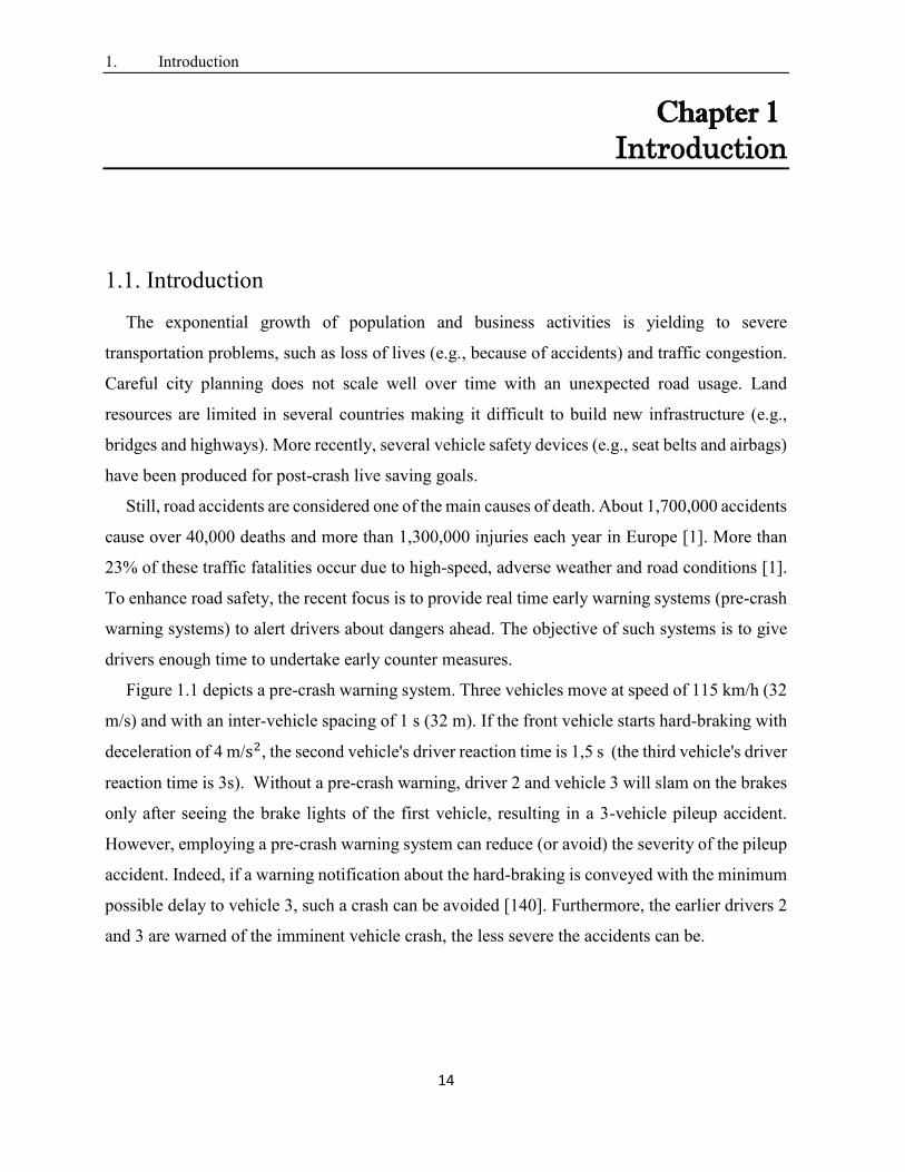
Figure 1.1 depicts a pre-crash warning system. Three vehicles move at speed of 115 km/h (32
m/s) and with an inter-vehicle spacing of 1 s (32 m). If the front vehicle starts hard-braking with
deceleration of 4 m/s2, the second vehicle's driver reaction time is 1,5 s (the third vehicle's driver
reaction time is 3s). Without a pre-crash warning, driver 2 and vehicle 3 will slam on the brakes
only after seeing the brake lights of the first vehicle, resulting in a 3-vehicle pileup accident.
However, employing a pre-crash warning system can reduce (or avoid) the severity of the pileup
accident. Indeed, if a warning notification about the hard-braking is conveyed with the minimum
possible delay to vehicle 3, such a crash can be avoided [140]. Furthermore, the earlier drivers 2
and 3 are warned of the imminent vehicle crash, the less severe the accidents can be.
1. Introduction
15
Figure 1.1. Illustration of a pre-crash warning system [140]
Intelligent Transportation Systems (ITS) using wireless communications and sensors are
suggested to improve road safety. Here, roads and vehicles become not only a transportation
platform but also a communication platform. Vehicular Ad hoc Networks (VANET) represent
the key technology of ITS by enabling wireless communication among vehicles; indeed, it has
been reported that VANETs have the potential to address more than 79% of all crashes involving
unimpaired drivers. In VANET, every vehicle is equipped with a wireless communication device
that enables Vehicle-to-vehicle (V2V) communication and Vehicle-to-Infrastructure (V2I)
communication. Both V2V and V2I communications are standardized by the dedicated short-
range communication DSRC standard [2].
The rest of the chapter is organized as follows. Section 1.2 presents V2V and V2I
communication modes, the DSRC standard in the U.S, characteristics of VANETs and a sample
of applications that can be implemented in VANETs. Section 1.3 describes our motivation and
problem statement. Section 1.4 presents thesis contributions. Section 1.5 presents thesis
organisation.
1. Introduction
16
1.2. Vehicular Ad Hoc Networks
1.2.1. V2V and V2I communication modes
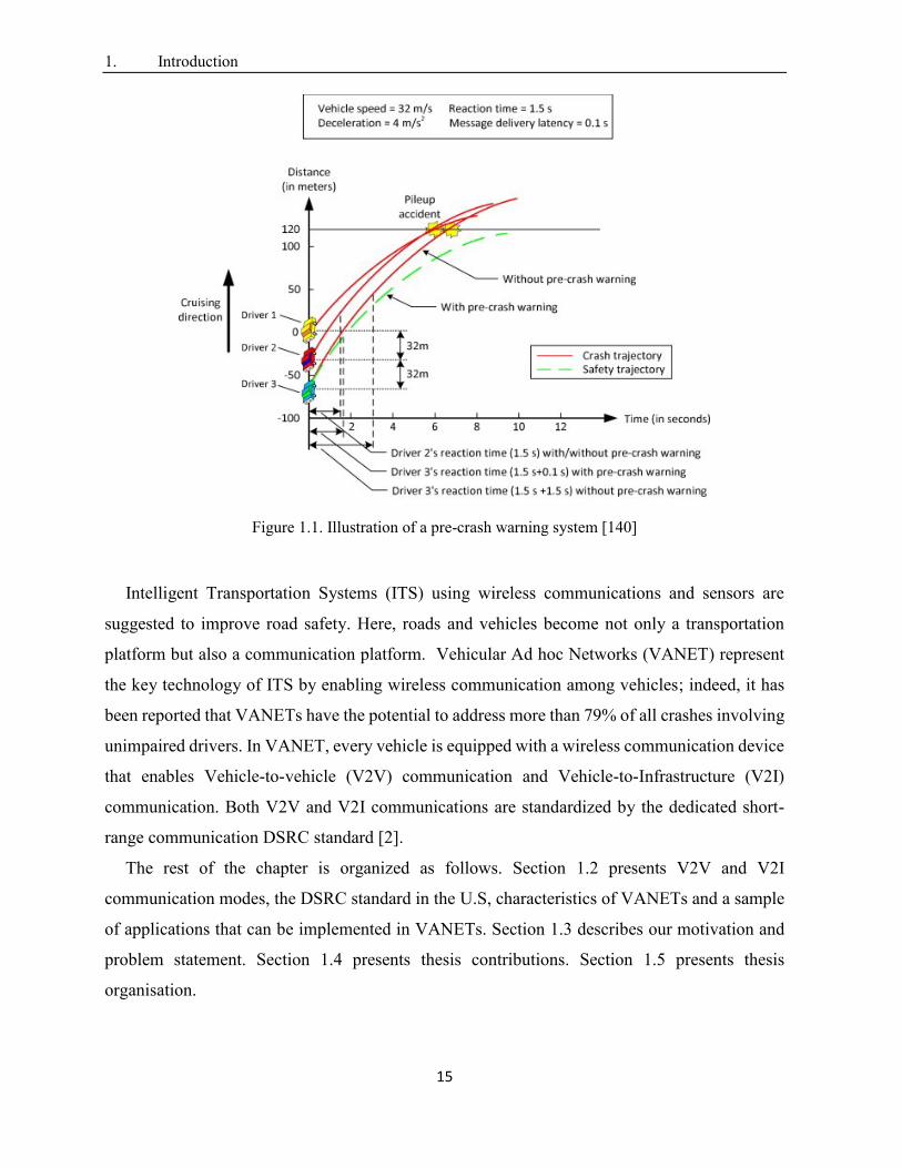
VANET architecture supports V2V and V2I communications. V2V communication allows
the communication among neighboring vehicles. V2I communication allows the communication
between vehicles and fixed roadside units (RSUs). RSUs are installed at fixed roadside locations.
Each vehicle is equipped with a wireless communication device, called an on-board unit (OBU),
to form wireless communication links between vehicles (or RSUs). Hence, OBUs communicate
with other neighboring OBUs or with neighboring RSUs. RSUs have higher radio coverage than
vehicles. One of the main benefits of RSU infrastructure is to relieve poor network connectivity
(e.g., RSUs can increase the overall coverage of a vehicular network and enhance network
performance (i.e., delay) between disconnected vehicles) [8]. RSUs are connected to the Internet
via either wireline or wireless networks. In addition, by establishing connection with an RSU, a
vehicle can access the Internet (see Figure 1.2).
Figure 1.2 Vehicular Ad Hoc Network (V2V and V2I communications)
1. Introduction
17
The radio communication range varies based on the transmission power of the transceiver [2].
The maximum radio communication range of an OBU device is smaller than 1 km. If a message
needs to be disseminated to nodes2 beyond the radio range, blind flooding (i.e., every vehicle
within a target area for message transmission retransmits the message) extends the radio coverage
range of a node by multi-hop links. In dense networks, flooding degrades considerably the
network performance (e.g., due to high packet collisions). The alternative techniques are non-
flooding. These techniques, called message dissemination, allows only some vehicles, called
“forwarders”, to retransmit the message, which is reviewed in Chapter 2 of this dissertation.
1.2.2. DSRC Overview
Dedicated Short Range Communication (DSRC) [2] is the emerging wireless technology for
communication between OBUs and RSUs. The term “Dedicated” refers to the fact that the
Federal Communications Commission (FCC) in the U.S, allocated 75 MHz of licensed spectrum
in the 5.850–5.925 GHz frequency band, for vehicular communication [3]. The term “Short
Range” conveys that communication takes place over short range radio links (i.e., hundreds of
meters). The primary motivation for DSRC deployment is crash-prevention. DSRC frequency
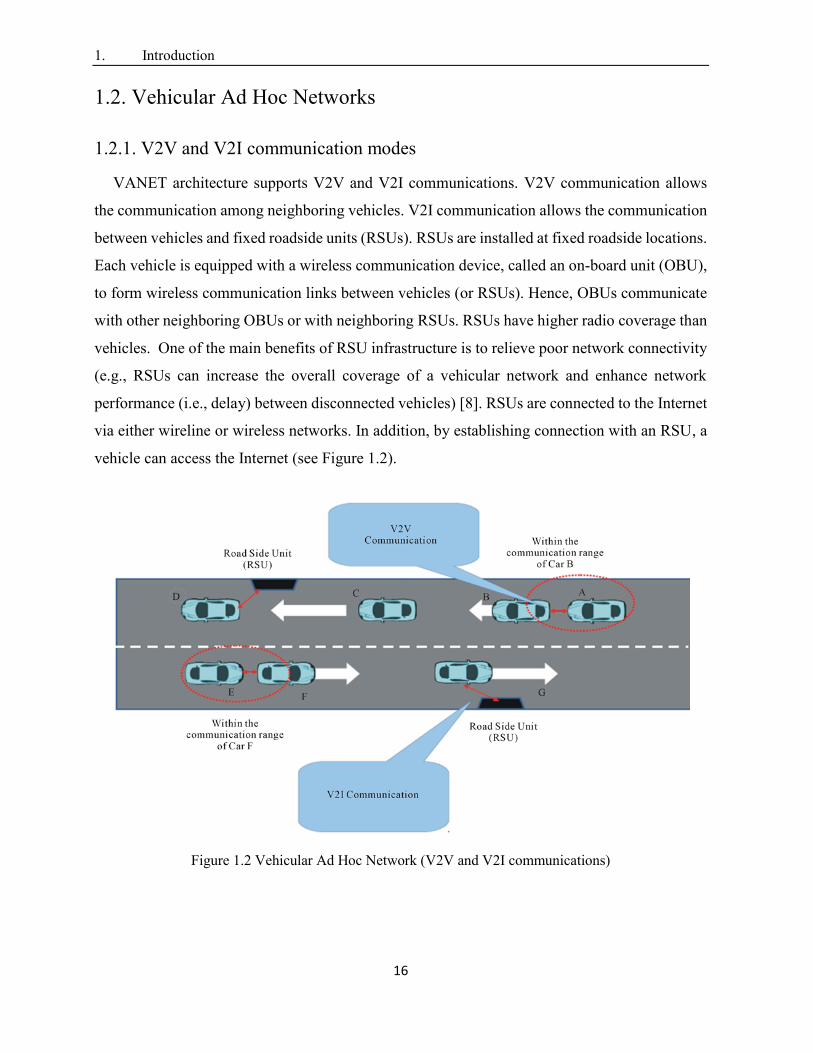
band is divided into one Control Channel (CCH) and six Service Channels (SCHs). Safety
messages are exchanged on CCH. Figure 1.3 shows the protocol stack for DSRC communication
in the U.S.
Figure 1.3. Layered DSRC architecture in the U.S.
2 Nodes designate either vehicles or RSUs
802.11p
802.11p 1609.4
LLC IEEE 802.2
IPv6
TCP/UDP
HTTP 1609.1
WSMP 1609.3 1609.2 Security
Physical layer
MAC layer
(MAC)
LLC layer
Network layer
Transport layer
Application layer
1. Introduction
18
At the Physical (PHY) layer and medium access control (MAC) layer, DSRC uses IEEE 802.11p
which is a modified version of IEEE 802.11 (WiFi) standard. In the next subsections, we present
the DSRC Physical (PHY) layer and the DSRC Medium access control (MAC) layer.
1.2.2.1. Physical Layer
The physical layer of IEEE 802.11p is similar to IEEE 802.11as, with some adaptations for
VANET characteristics. DSRC/IEEE 802.11p PHY reduces the signal band from 20MHz to
10MHz. As a result, the values of physical parameters (e.g., guard interval and duration of a data
symbol) for IEEE 802.11p are doubled compared to the IEEE 802.11a PHY. The DSRC PHY
protocol is defined in IEEE 802.11. The physical layer protocol is divided into two sublayers:
the physical medium dependent (PMD) sublayer and the physical layer convergence procedure
(PLCP) sublayer. PMD interfaces directly with the wireless medium. It uses the familiar
orthogonal frequency division multiplexing (OFDM) technique, which was originally added to
802.11 in the 802.11a amendment. PLCP defines the mapping between the MAC frame and the
basic PHY layer data unit. In a transmitter, PLPC processes the bytes in a MAC frame in order
to be transmitted into OFDM symbols for transmission over the air by PMD. PLPC adds PHY
layer overhead to the MAC frame to create the PHY Protocol Data Unit (PPDU). The MAC
sublayer passes 3 parameters to PLPC: (1) length of the MAC frame; (2) transit data rate; and (3)
transmit power. In a receiver, PLPC performs the inverse function to extract the MAC frame
from PPDU. Furthermore, PLPC provides the received signal strength interference (RSSI). When
PLPC requests PMD to transmit a frame, the PMD sublayer performs the OFDM modulation and
transmits PPUD over the air. The PMD receiver performs the demodulation. The PMD sublayer
passes RSSI with the received frame up to the PLPC sublayer. At the receiver, 802.11p does not
modify the sensitivity requirement which is a function of the data rate of the packet. For 10 MHz,
minimum sensitivity levels vary from -85 dBm at 3Mb/s to -68dBm at 27Mb/s. DSRC on 10
MHz channels is more suited to delay and Doppler effects in a vehicular environment.
1.2.2.2. MAC Sublayer
The MAC layer of IEEE 802.11p is based on IEEE 802.11a. Particularly, for V2V, DSRC
defines a new type of 80211 communication, Outside the Context of a Basic service set (OBC),
to cope with VANET high mobility (e.g., short-duration communication link in case of two
1. Introduction
19
vehicles with opposing driving directions). OBC does not require neither authentication nor
association when exchanging data frames. To distinguish frames sent in OCB mode, 802.11p sets
the value of Basic Service Set (BSS) identifier (BSSID) field in the data frame header to
0xFFFFFF, also known as wildcard value. IEEE 802.11p utilizes the Enhanced Distributed
Channel Access (EDCA) mechanism to provide service differentiation. The basic mechanism of
sharing the medium between vehicles relies on the Distributed Coordination Function (DCF) of
CSMA/CA. IEEE 802.11p does not alter CSMA/CA rules in the 802.11 [2] (the principles of
"carrier sensing" and "collision avoidance"); carrier sensing is achieved through Clear Channel
Assessment (CCA) and/or Network Allocation Vector (NAV). Collision avoidance is achieved
using a back-off procedure. In a simplest communication scenario under CSMA/CA, if a vehicle
has a frame to send, it first senses the wireless medium for Distributed Inter-frame Space (DIFS).
If the medium is idle, the vehicle begins transmission of its frame. If the medium is busy, the
vehicle performs a random back-off to wait before transmission. The countdown begins when
the medium becomes idle. The above mechanism applies to both broadcast and unicast frames.
Besides, EDCA enables 4 Quality of Service (QoS) classes by prioritizing data traffic within
each node. Hence, each node maintains four queues. These queues have different Arbitrary Inter
Frame Spacing (AIFS) and different back-off parameters; the higher the priority, the shorter
AIFS. Each transmission queue of an Access Category (AC) operates as an independent DCF
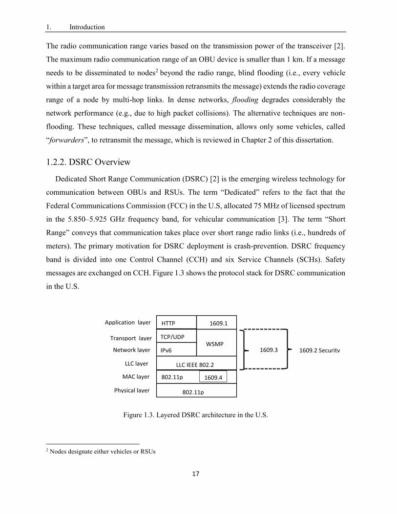
station (STA). Figure 1.4 shows the basic channel access procedure in DCF. Basically, in unicast
communication, the sender transmits a packet and waits for an acknowledgment (ACK). If no
ACK is received, a back-off procedure is invoked before a retransmission is allowed. For every
attempt to send a packet, the size of the contention window (CW) is doubled from its initial
value (CW min) until a maximum value (CW max) is reached. This enables to separate the nodes
that want to send at the same time. After a successful transmission (or when the maximum
number of channel access attempts is reached), the contention window is reset to its initial value.
Furthermore, vehicles can employ RTS/CTS control packets handshake to combat the hidden
terminals problem. However, in broadcast communication, a frame is not acknowledged and is
sent only once.
1. Introduction
20
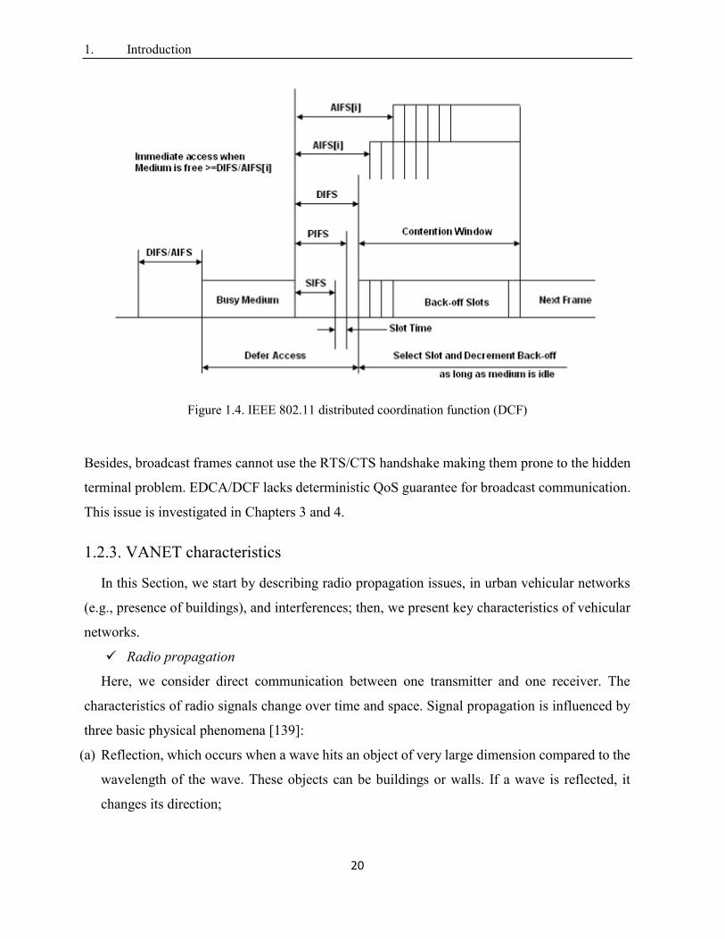
Figure 1.4. IEEE 802.11 distributed coordination function (DCF)
Besides, broadcast frames cannot use the RTS/CTS handshake making them prone to the hidden
terminal problem. EDCA/DCF lacks deterministic QoS guarantee for broadcast communication.
This issue is investigated in Chapters 3 and 4.
1.2.3. VANET characteristics
In this Section, we start by describing radio propagation issues, in urban vehicular networks
(e.g., presence of buildings), and interferences; then, we present key characteristics of vehicular
networks.
Radio propagation
Here, we consider direct communication between one transmitter and one receiver. The
characteristics of radio signals change over time and space. Signal propagation is influenced by
three basic physical phenomena [139]:
(a) Reflection, which occurs when a wave hits an object of very large dimension compared to the
wavelength of the wave. These objects can be buildings or walls. If a wave is reflected, it
changes its direction;
1. Introduction
21
(b) Diffraction, which occurs if a wave hits an object that has sharp irregularities (e.g., building
edges). In this case, many secondary waves occur that continue propagating;
(c) Scattering, which occurs if the propagation medium contains a high number of objects that
are small compared to the wavelength, e.g., street signs. These objects split the wave into
several ones. At the receiver, several of the waves arrive and they interfere with each other
resulting in interferences between different propagation paths of one transmitted signal [139].
These effects are caused by the physical environment (e.g., frequency, distance, antenna
heights, atmospheric conditions, and the presence of buildings) in which the signal propagates.
To describe these effects on the signal, three types of radio propagation models are used [139]:
(i) large-scale path loss; (ii) shadowing or large-scale fading; and (iii) small-scale fading. A
possible way to describe the reception characteristics of a signal lies in subsequently applying
mathematical descriptions of the three models to the transmitted signal: first, the signal
attenuation due to the path loss is calculated, then, shadowing effects are added, and finally, the
effects of fading are applied [139].
Interference
Here, we consider multiple transmissions in the network. Basically, there are two sources of
interference on a communication channel from the perspective of a receiving node (We focus on
the common control channel (CCH)): (a) Multi-path interference; and (b) Multi-user
interference.
Multi-path interference is the fact that a transmission follows multiple paths, as explained
in the previous paragraph.
Multi-user interference is the fact that multiple transmissions overlap on the same channel
[139]. Multi-user interference occurs for two main raisons: (a) two senders that are
geographically close to each other (in the radio ranges of each other) access the channel
at the same moment in time. This interference can be mitigated using medium access
schemes that are based on CSMA/CA. Indeed, using CSMA/CA, the channel may be
accessed only if a node that wants to transmit a message does not sense any other
transmission on the channel (see Section 1.2.2.2 for details about the EDCA/DCF
scheme). The use of a random number of back-off slots reduces the probability that two
senders that are geographically close to each other access the channel at the same
moment. However, the back-off procedure cannot ideally avoid such simultaneous access

1. Introduction
22
in broadcast transmission, resulting in collisions. This phenomenon is serious in multi-
hop broadcasting that uses flooding (see. Section 2.2 of Chapter 2 for more details). Non-
flooding techniques in consequence reduce the number of transmitters (forwarders) which
can reduce probability of transmitting on the same slot; and (b) hidden terminal, defined
as the access to the channel during the transmission of another packet. Hidden terminal
is the primary cause of multi-user interference. Indeed, the CSMA/CA decides on
whether the channel is in use or not by measuring the signal power on the wireless
channel. The received power may become low over distance due to path loss (In chapter
3, we provide a method to compute signal power attenuation rate caused by background
traffic at each receiver and we find out that this rate is proportional to the packet collision
rate that occurs at same receiver). As a result, a node may sense the channel idle while
another transmission that has a low reception power is ongoing at the specific receiver.
The node, thus, decides to transmit although there is an ongoing transmission resulting in
collision at a receiver positioned between the two transmitters [139].
Mobility
VANET is a highly dynamic and mobile environment. Vehicles have mobile characteristics
(i.e., each driver has its own moving way to reach an individual geographical location). Yet, the
degree of freedom is limited by the road network, traffic rules and the behavior of other vehicles
on the same road. The mobility of nodes affects communication, as radio propagation
characteristics and network topology continuously change [139].
Distributed decentralized system
In VANET, a huge number of mobile vehicles and stationary RSUs participate in the
communication. Such a communication system is distributed and decentralized. Hence, a
centralized control that provides management and coordination functionality is not possible.
Instead, immediate and direct communication among all nodes is established and provided in a
decentralized manner. Such a decentralized control leads to interferences of uncoordinated
transmitters [139].
Broadcast communication
Data traffic generated by safety applications is broadcast traffic. Broadcast means that the
transmitted data (e.g., crash warning) is not addressed to one specific vehicle, but to all vehicles
positioned in the surrounding of the transmitter. The challenge of data dissemination/broadcast
1. Introduction
23
is that a reception by every node within a specified surrounding cannot be guaranteed as there is
no suitable way to acknowledge the reception of broadcast messages. Even if acknowledgement
schemes are used, it will not be possible to ensure that every possible receiver gets the message.
This is due, in part, to the fact that there is no information on how many nodes are potential
(good) receivers. Consequently, reliability of transmissions cannot be guaranteed for broadcast
communication. This makes the impact of interference even more severe in broadcast
transmissions.
1.2.4. VANET Applications
This section overviews vehicular applications, several user cases and their associated QoS
requirements. ITS applications can be classified into three categories: (a) road safety
applications; (b) traffic efficiency and management applications; and (c) infotainment
applications.
1.2.4.1 Road Safety Applications
Safety applications are employed to decrease the probability of crashes. The U.S. Vehicle
Safety Communications Consortium has identified more than 75 application scenarios enabled
by DSRC [4]. These applications can be accomplished by sharing, between vehicles and RSUs,
(a) periodic messages (also called beacons): they are preventive safety messages used, for
example, to predict collisions. Note that beacons can be also used by non-safety applications
(e.g., road traffic control). Exchange of beacons makes vehicles aware of their environment;
indeed, beacons contain information about the state of the sending vehicle (e.g., position,
direction, and speed); and (b) event-driven messages (also called emergency or safety messages):
they are generated due to the detection of unsafe situations (e.g., a car crash). More specifically,
a vehicle generates an emergency message on detecting a danger. A vehicle is defined as the
source node when it detects the danger on the road. The emergency message should be delivered
to all nodes in the target area, also called risk zone3, exposed to the potential danger as quickly
as possible. The risk zone is extended behind the source vehicle along the road. All vehicles in
the risk zone should be notified ahead of time, before they reach the potential danger location, to
allow them to take action in time (e.g., slow down or brake). Emergency messages are
3 Risk zone designates the target area of an emergency message
1. Introduction
24
disseminated in a broadcast fashion since their content is beneficial to all vehicles in the risk
zone. Safety applications have strict reliability and delay requirements (See Table 1.1).
Table 1.1. Example of vehicular safety applications: communication requirements [5][136]
Safety application Transmit mode Range Max. Latency
(ms)
Reliability
requirement
Over taking vehicle warning Periodic ≤ 250 1000 High
Head on collision warning Periodic ≤ 250 200 High
Intersection collision warning Event-driven ≤ 300 100 High
Post-crash Notification Event-driven ≤ 300 500 High
Cooperative collision warning Event-driven ≤ 300 100 High
In the following, we present some examples of safety applications and their use cases.
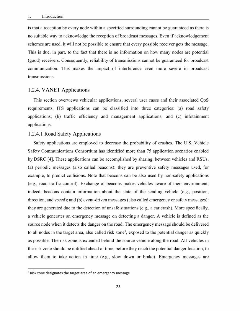
Overtaking vehicle warning (OVW)
OVW [137] [138] aims at preventing collision between vehicles in an overtake situation, in
urban roads. A possible use case of OVW application is depicted in Figure 1.5; vehicle 1 is
willing to overtake vehicle 3. A Powered Two Wheeler (PTW) 2 is already doing an overtaking
maneuver on vehicle 3. Collision between vehicle 1 and PTW 2 is prevented when PTW 2
informs vehicle 1 to stop its overtaking procedure. This situation is critical for PTW users due to
blinds spots and differential of speed between PTW and a car which does not allow the driver to
be aware of the presence of a motorcyclist. The purpose behind this use case is to avoid collision
between PTW and vehicles by giving a warning to the vehicle.
.
Figure 1.5. Safe overtaking in urban roads
1. Introduction
25
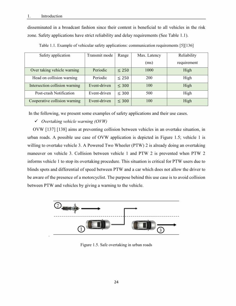
Head on collision warning (Do Not Pass Warning)
DNPW [137] [138] reduces the risk of a head collision by sending early warnings to vehicles
that are traveling in opposite directions. This use case is also denoted as “Do Not Pass Warning”.
As shown in Figure 1.6, vehicle 1 attempts to overtake vehicle 3 which obstructs the driver's 1
field of view, while vehicle 2 is approaching from the opposite lane. The purpose behind this use
case is to warn the driver of vehicle 1, of an incoming vehicle in the adjacent lane. Thus, vehicle
1 needs to delay or abort the overtaking manoeuvre. This allows to avoid accidents linked to head
on collision situations.
Figure 1.6. Head on collision warning
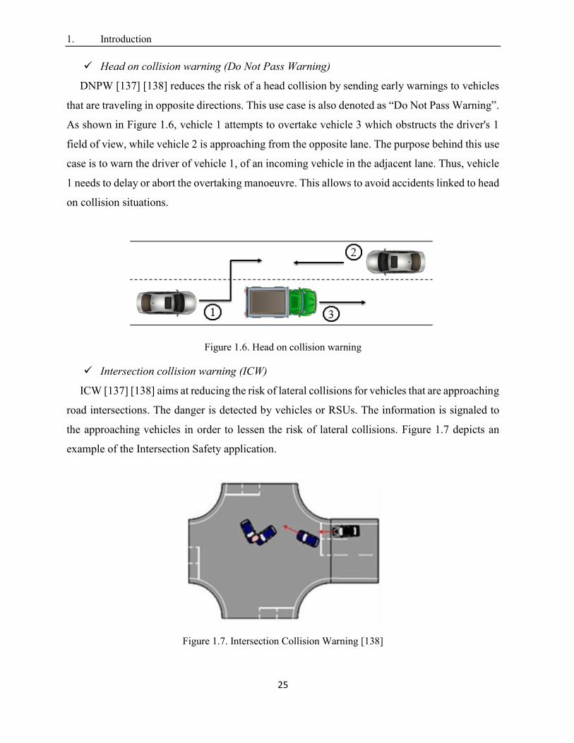
Intersection collision warning (ICW)
ICW [137] [138] aims at reducing the risk of lateral collisions for vehicles that are approaching
road intersections. The danger is detected by vehicles or RSUs. The information is signaled to
the approaching vehicles in order to lessen the risk of lateral collisions. Figure 1.7 depicts an
example of the Intersection Safety application.
Figure 1.7. Intersection Collision Warning [138]
1. Introduction
26
A crash happens at an intersection creating a dangerous situation. Now, drivers approaching
this intersection will be warned about the crash. The purpose of this use case is to avoid critical
situations resulting from an accident beforehand. Intersections are probably the most complex
part of road infrastructures and places where collisions can result in serious injury or death. An
accident at an intersection can result in other accidents as an unforeseen situation would exist. At
intersections, traffic-flow is very complex. Hence, the driving behaviour of other drivers could
change immediately, due to such unforeseen situations [138].
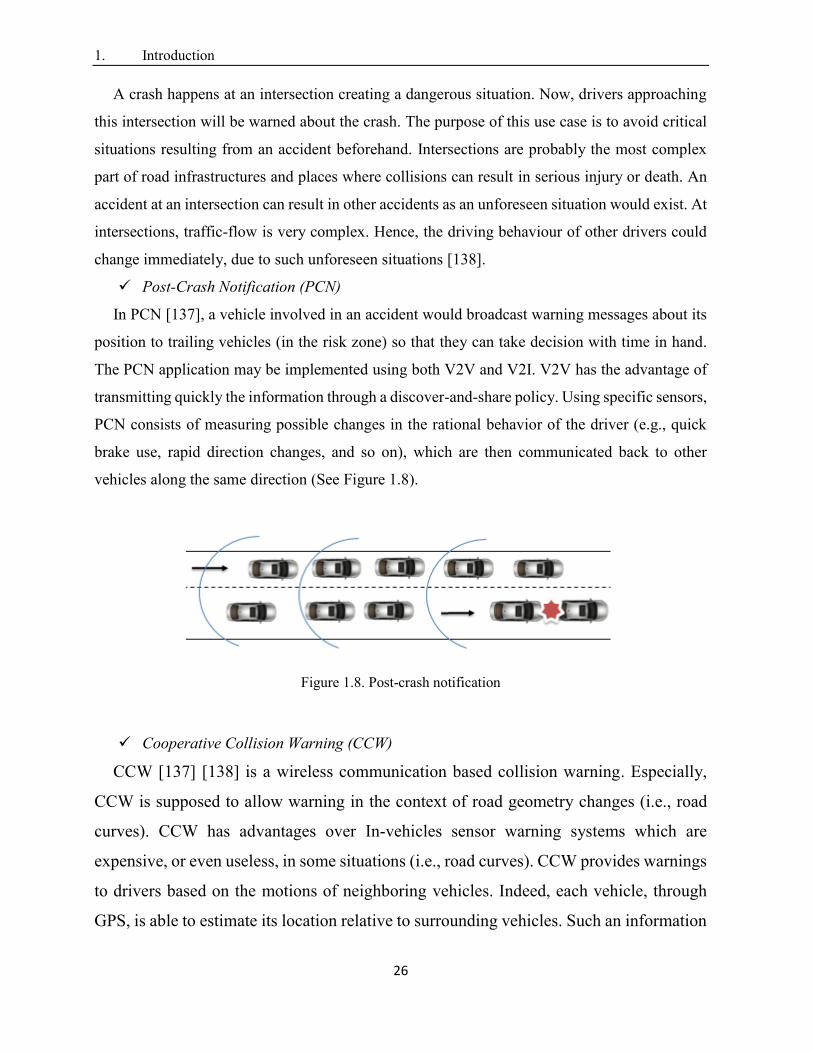
Post-Crash Notification (PCN)
In PCN [137], a vehicle involved in an accident would broadcast warning messages about its
position to trailing vehicles (in the risk zone) so that they can take decision with time in hand.
The PCN application may be implemented using both V2V and V2I. V2V has the advantage of
transmitting quickly the information through a discover-and-share policy. Using specific sensors,
PCN consists of measuring possible changes in the rational behavior of the driver (e.g., quick
brake use, rapid direction changes, and so on), which are then communicated back to other
vehicles along the same direction (See Figure 1.8).
Figure 1.8. Post-crash notification
Cooperative Collision Warning (CCW)
CCW [137] [138] is a wireless communication based collision warning. Especially,
CCW is supposed to allow warning in the context of road geometry changes (i.e., road
curves). CCW has advantages over In-vehicles sensor warning systems which are
expensive, or even useless, in some situations (i.e., road curves). CCW provides warnings
to drivers based on the motions of neighboring vehicles. Indeed, each vehicle, through
GPS, is able to estimate its location relative to surrounding vehicles. Such an information
1. Introduction
27
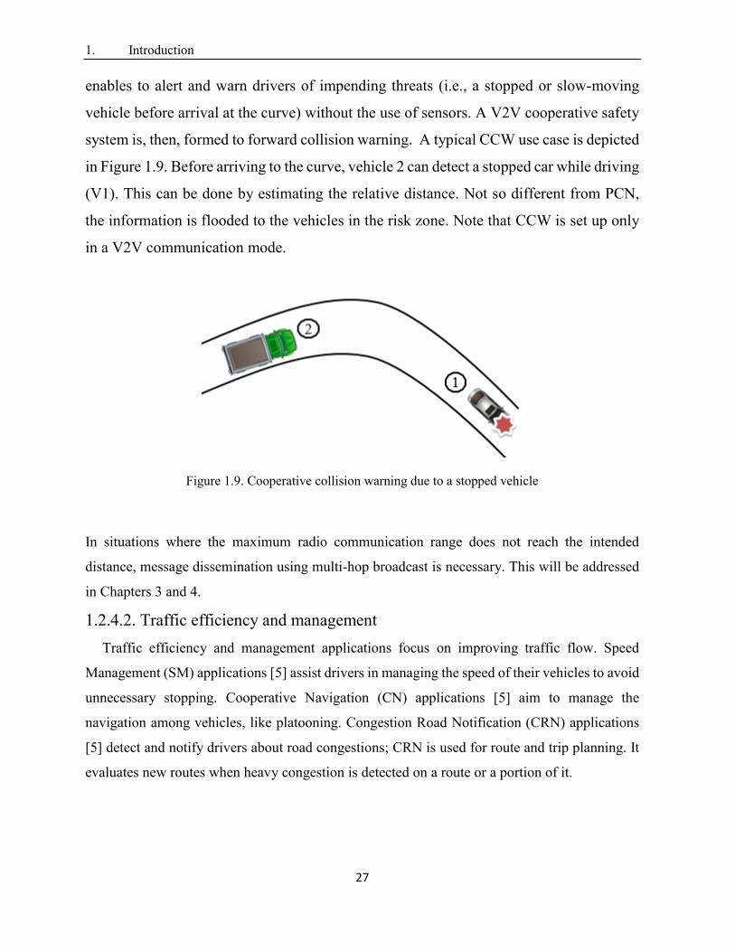
enables to alert and warn drivers of impending threats (i.e., a stopped or slow-moving
vehicle before arrival at the curve) without the use of sensors. A V2V cooperative safety
system is, then, formed to forward collision warning. A typical CCW use case is depicted
in Figure 1.9. Before arriving to the curve, vehicle 2 can detect a stopped car while driving
(V1). This can be done by estimating the relative distance. Not so different from PCN,
the information is flooded to the vehicles in the risk zone. Note that CCW is set up only
in a V2V communication mode.
Figure 1.9. Cooperative collision warning due to a stopped vehicle
In situations where the maximum radio communication range does not reach the intended
distance, message dissemination using multi-hop broadcast is necessary. This will be addressed
in Chapters 3 and 4.
1.2.4.2. Traffic efficiency and management
Traffic efficiency and management applications focus on improving traffic flow. Speed
Management (SM) applications [5] assist drivers in managing the speed of their vehicles to avoid
unnecessary stopping. Cooperative Navigation (CN) applications [5] aim to manage the
navigation among vehicles, like platooning. Congestion Road Notification (CRN) applications
[5] detect and notify drivers about road congestions; CRN is used for route and trip planning. It
evaluates new routes when heavy congestion is detected on a route or a portion of it.
1. Introduction
28
1.2.4.3. Infotainment applications
The aim of infotainment applications is to offer comfort to drivers and/or passengers. In
modern cities, people spend a considerable amount of time commuting by car from one place to
another. A plethora of infotainment applications [6] are made available to vehicular users
anytime and anywhere. This calls for vehicular networks to provide Internet access to vehicles.
Infotainment applications include content download, media streaming, VoIP, social networking,
gaming, cloud access, etc. Infotainment applications will be offered to passengers using service
channels. A number of these applications is based on delay-sensitive video streaming requiring
real-time transmission. To enhance the end-user experience, parameters such as frame rate, frame
dropping, and timeliness are the basis of a good video quality. Hence, infotainment applications
require low end-to-end delay and high reliability (low packet loss). More details about QoS
support in infotainment applications can be found in [7] [8] [9].
Internet Access
In-vehicle Internet access [10] allows a vehicle to connect to the Internet (e.g., to use
infotainment applications) through an Internet gateway. Typically, a vehicle connects to an
Internet gateway in its vicinity. In case no Internet gateway in the range, a vehicle relies on multi-
hop communications to connect to an Internet gateway beyond its transmission range. An Internet
gateway discovery protocol is, then, required to discover routes (i.e., an established route is a
fixed succession of nodes between the source and the destination) to Internet gateways not in the
range. Internet service providers (ISPs) offer Internet access through various wireless
technologies (i.e., LTE) using Internet gateways. Once connected to Internet, a vehicle can access
Internet services (i.e., email). In the following, we briefly describe Internet gateways as well as
the gateway discovery/advertisement process.
Internet gateway
Traditionally, an Internet gateway is an RSU, installed in fixed position along a roadside [36].
Unfortunately, Internet access through RSUs requires pervasive RSUs to ensure each vehicle is
in RSU’s transmission range [11] (i.e., the typical range of an RSU is few hundred meters). Such
a requirement incurs high infrastructure deployment cost. Several research efforts
[12][13][14][15][16] are proposed to optimally place RSUs. Indeed, deploying a new RSU needs
intensive investigation [11]; for instance, the land where to place a new RSU may be private
requiring owner permission. It may be difficult, if not impossible, to get such a permission.
1. Introduction
29
Therefore, deploying new RSUs often requires a large amount of investment and elaborate
design, especially at the city scale. Consequently, Internet access systems that rely only on
roadside infrastructure are impracticable to be implemented. Recently, the concept of long-term
evolution (LTE)-connected vehicles [17] (i.e., a vehicle equipped with 802.11p and LTE
interfaces) has received a lot of attention. Once in the range of a LTE base station, the vehicle
gets Internet access. Actually, LTE provides a robust mechanism for mobility management of
vehicles [18] (i.e., supports data rate of 10 Mbps with speed up to 140 km per hour). LTE also
fits the bandwidth demands and the quality of service requirements of infotainment applications
[18]. However, mobile data is experiencing explosive growth [19]; this makes LTE cellular
infrastructure bandwidth not able to keep up with connecting high number of connected vehicles
[20]. Also, it has been reported that cellular infrastructure connectivity cannot evolve once it is
installed [17]. Furthermore, many vehicles incur frequent handoffs, because of high mobility,
requiring higher bandwidth [21]. Hence, allowing only some connected vehicles to operate as
Internet gateways (mobile Internet gateways) to other vehicles may be effective [22]. Various
Internet access systems using connected vehicles as Internet gateways [23] [24] [25] [26] have
been proposed. Getting Internet access through either RSUs ([12] [13] [14]) or connected
vehicles ([23] [24] [25] [26]) relies on multi-hop communication links [36].
Gateway discovery/advertisement
Gateway discovery/advertisement is the process of finding a gateway that matches the
requirements of requestors (i.e., vehicles). Conventionally, an Internet gateway periodically
advertises its services (i.e., broadcasts an advertisement message) to announce its presence in
either one-hop or multi-hop area using flooding. Furthermore, a requester (vehicle), in turn,
discovers and selects gateways using a gateway discovery scheme; the requestor sends discovery
messages, in the network to establish a route to a convenient gateway. Route discovery process
relies on multi-hop broadcasting to find an appropriate Internet gateway. Existing gateway
discovery/advertisement schemes are reviewed in Chapter 2.
1.3. Motivations and Problem statement
V2V and V2I communications are expected to enable diverse safety and infotainment
applications. IEEE DSRC/802.11p is the emerging communication standard for vehicular
communication. Broadcast is the preferred communication mode for vehicular applications.
1. Introduction
30
In big cities, several emergency events have to coexist together to achieve life-saving goals.
On detecting an unexpected event (i.e., a traffic accident), a vehicle immediately issues an event-
driven message to notify neighboring vehicles/drivers ahead of time to allow them to take action
in time. Conceived to be just up to few hundred meters [27], an emergency message has to be
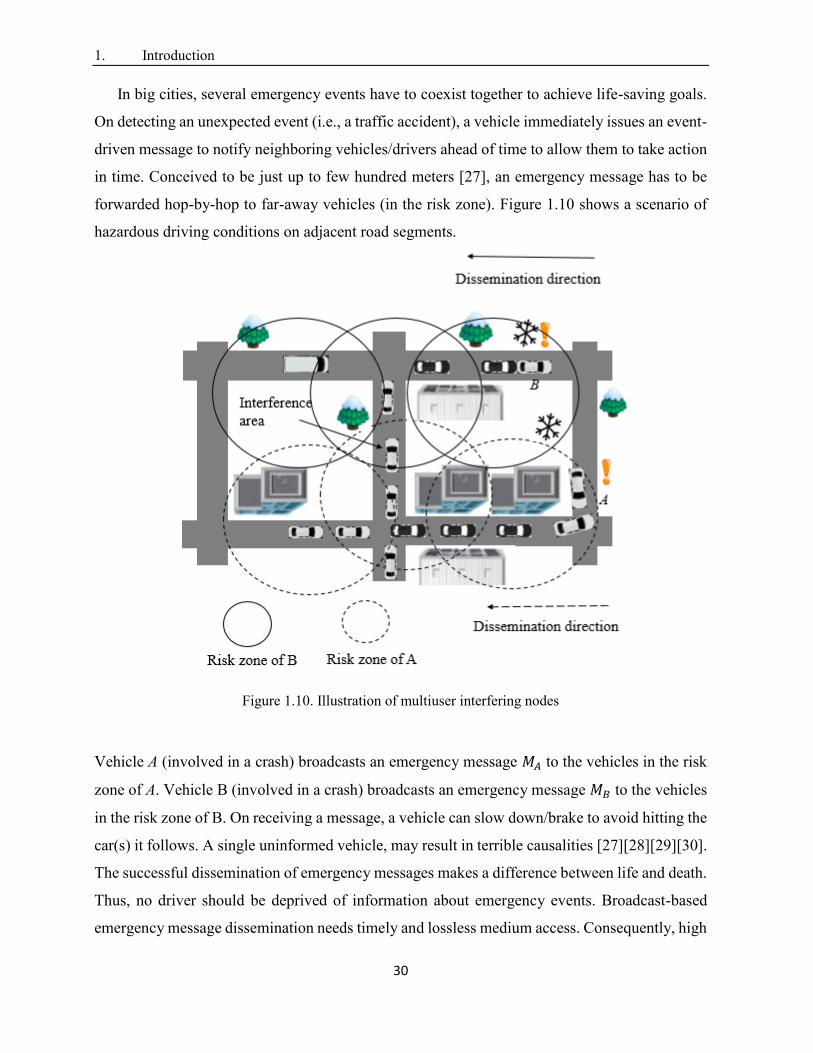
forwarded hop-by-hop to far-away vehicles (in the risk zone). Figure 1.10 shows a scenario of
hazardous driving conditions on adjacent road segments.
Figure 1.10. Illustration of multiuser interfering nodes
Vehicle A (involved in a crash) broadcasts an emergency message 𝑀𝐴 to the vehicles in the risk
zone of A. Vehicle B (involved in a crash) broadcasts an emergency message 𝑀𝐵 to the vehicles
in the risk zone of B. On receiving a message, a vehicle can slow down/brake to avoid hitting the
car(s) it follows. A single uninformed vehicle, may result in terrible causalities [27][28][29][30].
The successful dissemination of emergency messages makes a difference between life and death.
Thus, no driver should be deprived of information about emergency events. Broadcast-based
emergency message dissemination needs timely and lossless medium access. Consequently, high
1. Introduction
31
reliability of message dissemination is required (e.g., the probability of packet reception should
be greater than 0.99 [29]).
Infotainment applications call for vehicular communication networks to support Internet services
in vehicles [31]. Indeed, In-vehicle Internet access [10] allows a vehicle to connect to the Internet
through an Internet gateway. Traditionally, an Internet gateway is RSU, installed at fixed position
along a roadside. Recently, the concept of LTE-connected vehicles [17] (i.e., a vehicle equipped
with 802.11p and LTE interfaces) has received a lot of attention. Once in the range of a LTE
base station, the vehicle gets Internet access. Allowing some connected vehicles to operate as
Internet gateways (mobile Internet gateways) to other vehicles may be effective [22]. Getting
Internet access through either RSUs ([12] [13] [14]) or connected vehicles ([23] [24] [25] [26])
relies on multi-hop communication links. Typically, a vehicle connects to a gateway in its
vicinity. In case no Internet gateway in the range, a vehicle relies on multi-hop communications.
To do so, an Internet gateway discovery scheme is required to discover routes (i.e., an established
route is a fixed succession of nodes between the source and the destination) to Internet gateways
not in the range. Internet gateway discovery schemes should be enable the establishment of
reliable paths to Internet gateways. The discovery process can be done in two ways: (1) a
gateway periodically sends advertisement messages; or (2) a requestor sends discovery messages.
If some nodes along the path have low reception probability, the communication would be
stopped.
Nevertheless, many factors can influence probability of successful message reception in
wireless communications. In vehicular networks, vehicles share a common wireless channel by
using the same radio frequencies. Each node competes for channel access when it needs to
transmit, without any guarantee of success. Typically, several factors reduce probability of
successful message reception in wireless communications. Random loss is caused by lossy
wireless channels and node mobility. In city road networks, severity of interfering nodes
increases (i.e., overhearing a packet not intended for the receiving node is considered as
interference) [29] [30]. Vehicles may receive signals from other vehicles on adjacent streets.
Both periodic messages (i.e., beacons) and emergency messages [30] are transmitted on CCH.
Beacons increase the severity of interfered/collided packets. Furthermore, high mobility of
vehicles makes reliability of communication in vehicular networks more complex [27].
1. Introduction
32
Despite DSRC/802.11p based broadcast has the potential to provide low latency in one-hop
[28], it is reported to be defective in terms of reliability making it a major reason that hinders the
deployment of IEEE DSRC/802.11p [32]. IEEE DSRC/802.11p defines the MAC layer to be
based on CSMA/CA [32] with minor modifications. The channel access mechanism of
DSRC/80211p is Enhanced Distributed Channel Access (EDCA); it is not able to provide
predictable reliability for safety services. As a result, IEEE DSRC/802.11p MAC is not able to
guarantee broadcast reliability. More specifically, 802.11p MAC does not implement any
broadcast reliability mechanism [33] (e.g., DSRC/802.11p-based broadcast does not support
acknowledgement [32]). Comparing broadcast to unicast, no mechanism is used to alleviate the
hidden terminal problem (i.e., virtual carrier sensing is not used in IEEE 802.11 broadcast [32]).
Hence, the current draft of IEEE 802.11p MAC [34] [35] cannot meet strict reliability
requirements (e.g., 99%).
In multi-hop broadcasting, the probability of successful message reception decreases with the
number of hops [36]. Forwarder selection increases the probability of collisions/interference [28]
[33]. IEEE 802.11 MAC does not offer any specific support to improve reliability in multi-hop,
apart from the naïve flooding scheme [38]. However, such a solution may lead to the broadcast
storm problem [39] resulting in unreliability (i.e., high packet loss) and delayed communication
[39].
Thus, the objective of this dissertation is to contribute to the design and the evaluation of new
solutions that ensure efficient safety message dissemination (multi-hop communications) for
urban vehicular applications considering QoS requirements (i.e., delay and reliability). On one
hand, this work proposes two new emergency message dissemination schemes that provide best
reliability, compared to existing schemes, while satisfying delay requirements of safety
applications. On the other hand, it proposes and evaluates, an Internet access scheme that
provides Internet access to vehicles considering delay and reliability in order to enable
infotainment applications.
The first 2 contributions of this thesis address the problem of emergency message
dissemination, in urban VANETs, considering the requirements of safety applications in terms
of reliability (packet reception rate) and delay. In the literature, several approaches have been
proposed to deal with this issue. Among them, Several CSMA-based multi-hop broadcast
schemes have been proposed (e.g., [60][33][26][61][42][43][44][45]). Despite their good
1. Introduction
33
performance in low density network, exiting schemes sustain major shortcomings in urban
environment. On one hand, in fast schemes (e.g., [60][33][26][61][62]), the emergency message
is forwarded to selected forwarders in quick successions. However, in case the forwarder has
moved away or is malfunctioning, the multi-hop communication would not be possible. Efficient
schemes [42][43][44][45], on the other hand, propose techniques to mitigate the broadcast storm
problem. However, these schemes don’t consider MAC layer issues in their forwarding node
selection mechanism yielding to unreliable transmissions. They use control packet exchange
and/or acknowledgement packet and select a single forwarding node at each hop.
DSRC/802.11p-MAC [32] can’t characterize/detect random access events resulting in
unreliability. In harsh network conditions, a sender does not know whether its transmitted
message is successfully received or not. Recently, repetition-based broadcast MAC schemes
(e.g., [46][48]) have been proposed to enhance broadcast reliability for safety applications. The
basic idea is to repeat (i.e., transmit) the message multiple times within a frame in order to
increase reception probability; a frame consists of L time slots. Random repetitions schemes like
SFR [46] and AFR [46] randomly select repetition slots. It has been proved that selecting k slots
out of L raises the probability of successful message reception [46]. Expanding upon this finding,
structured repetitions are proposed to further protect repeated packets from hidden terminal
problem [49]. Positive Orthogonal Codes (POC), known as Uni-Polar orthogonal codes (UPOC)
[47], as structured repetition patterns, have been reported to suppress hidden terminal problem
[49]; an UPOC is a binary code of fixed length L, where cross-correlation between any pair of
code-words is less than a given value [49]. However, without evaluating the channel condition,
if fixed number of messages is forwarded within frame, we may be sending either too few or too
many packets. Too many packets may lead to considerable overhead and too few packets may
lead to unreliability. It is important to note that most existing Repetition-based MAC schemes
[46][48][49] are not compatible with emerging DSRC/802.11p [32].
The third contribution focuses on the problem of providing Internet access in urban vehicular
environments considering reliability and delay. Several Internet gateway discovery schemes (i.e.,
[50][26][51][52]) have been proposed in the literature. These schemes can be classified into three
categories: (1) Proactive approaches: Internet gateways advertise themselves in the whole
network; (2) Reactive approaches: vehicles that want Internet access, need to flood the network
for Internet gateway discovery; and (3) Hybrid approaches: Internet gateways advertise
1. Introduction
34
themselves to their neighbors (1 or n hops away); then, requesters send packets to find an Internet
gateway in these advertisement areas. Despite their good performance in 1-hop, existing schemes
(e.g., [26][51][53][54]) make use of link stability metric, which is based only on mobility metrics
(e.g.,relative motion between neighboring vehicles, speed, etc.), to determine paths to Internet
gateways. In city settings, such a selected route can be broken frequently owing to the high
mobility of vehicles. Any node that ensures progress toward the destination can be used for
forwarding. The forwarding decision is based on the position of destination vehicle and position
of one hop neighbors. However, the link to the selected node may be unreliable in harsh network
conditions leading to packet loss. From above discussions, we can conclude that the route
discovery schemes do not guarantee reliable communication, in city settings.
1.4. Thesis Contributions
The thesis consists of three contributions: (1) a reliable multi-hop broadcast scheme, called
Reliable Emergency Message Dissemination scheme (REMD), suitable for a wide range of
vehicular safety applications; (2) a new multi-hop broadcast scheme, called Bayesian networks
and unipolar orthogonal Code based Reliable multi-hop Broadcast (BCRB); and (3) an Optimal
Gateway Placement and Reliable Internet Access in Urban Vehicular Environments, called
reliable multi-hop Internet access system (called RICS) for urban vehicular environments.
In the first contribution, we propose REMD which is compatible with IEEE DSRC/802.11p.
Basically, REMD divides the target area into multiple cells (fine-grained vehicle positions) to
form adjacent grid-like zones. REMD consists of 5 proposals (1) a curve-fitting and polynomial
extrapolation based scheme to estimate, with good accuracy, the reception quality of link (in each
cell) in the transmission range of the sender; (2) a Max-Min optimisation problem and its
resolution that allows to determine an optimal number of repetitions (i.e., message transmissions)
to satisfy 1-hop reliability requirements. The problem resolution consists of calculating packet
reception rate (PRR) using exact Poisson’s binomial distribution. In urban vehicular networks,
Poisson’s binomial distribution does not follow an asymptotic Poisson distribution. We turn to
find the exact formula of probability mass function (p.m.f) of the distribution using a Fast Fourier
transform (FFT) based algorithm, labeled PMF-FFT. The time complexity of PMF-FFT is 𝑂(𝑛 ×
log(𝑛)), where n is number of cells. The input to the optimization problem is link reception
qualities computed in (1); (3) a UPOC-based scheme that carefully generates repetition patterns
1. Introduction
35
to minimize/avoid interferences between senders (vehicles) located on different road segments;
(4) a scheme that selects appropriate forwarders, at each hop, with the objective to satisfy multi-
hop reliability requirements. These forwarders, at each hop, cooperatively repeat the message
(based on the number of repetitions computed in (2) and repetition patterns determined in (3)) to
support reliability requirement in next hop; and (5) a sub-layer between MAC and LLC
responsible for generating broadcast repetitions. Simulations validated REMD (the analytical
model) and did show its outperformance compared to existing schemes in terms of reliability,
end-to-end delay and network load.
In the second contribution, we propose BCRB which is compatible with IEEE DSRC/802.11p;
it focuses on the main limitations of the first contribution: (1) link reception quality estimation:
BCRB proposes a Bayesian networks based scheme to estimate, with good accuracy, link
reception quality, at different locations in the zone covered by the transmission range of the
sender. This estimation is based on executing a training data collection phase (TDC) that exploits
beacons periodically generated by vehicles. To learn the Bayesian network, we make use of a
modified version of PC [111] algorithm, called V-PC, together with the Expectation
Maximization (EM) [116] algorithm. We make use of a graph indexing method to execute V-PC
in 𝑂(𝑛), where n is number of cells; and (2) Optimal number of repetitions: BCRB proposes a
more accurate resolution of the Max-Min optimisation problem that allows determining an
optimal number of repetitions (i.e., message transmissions) to satisfy 1-hop reliability
requirements for each receiver in transmission range. More specifically, BCRB guarantees
broadcast reliability for each receiver in the zone covered by the transmission range of the sender
using a combination of packet delivery probability (PDP) and packet reception rate (PRR)
metrics. Simulations validated our scheme (the analytical model) and did show its
outperformance compared to existing schemes in terms of reliability, end-to-end delay and
network load. Furthermore, simulations did show that both REMD and BCRB successfully
provide assured reliability while satisfying end-to-end delay requirements of safety applications.
BCRB could achieve less end-to-end delay and network load compared to REMD for all vehicle
densities. Also, BCRB outperforms REMD in terms of link reception quality estimation accuracy
especially in low vehicle density.
In the third contribution, we propose RICS for urban vehicular environments that uses our
proposed BCRB. We make use of both LTE-connected vehicles and the already deployed RSUs
1. Introduction
36
infrastructure as Internet gateways. Indeed, RSUs have a considerable impact on network
reliability, as they are fixed reliable nodes [55]. Because of random mobility of vehicles, there is
the possibility of network fragmentation. Static RSUs may act as bridges between fragmented
groups of vehicles [11]. LTE-connected vehicles enhance Internet gateways availability because
adding such vehicles (e.g., buses and taxis) doesn’t require additional infrastructure (e.g., land).
In [22], it has been reported that using connected vehicles as Internet gateways increases the
probability, for moving vehicles, to set up paths with fewer hops. To ensure reliable multi-hop
In-vehicle Internet access, we determine minimum possible communication hops, from a
requesting vehicle to a fixed/mobile Internet gateway, with high reliable advertisement message
dissemination. To accomplish this, we model the Internet gateways placement problem (called
GP) as a 2-dimentional k-center [56] optimization problem. This problem is known to be NP-
hard. We make a dimension reduction of the optimization problem and propose an exact time
resolution algorithm 𝑂(𝑛2 × log(𝑛)), where n is number of vehicles, to solve it. In addition to
computing minimum communication hops, we implement an Internet gateway discovery
protocol (using BCRB) which exploits the reception quality of 802.11p wireless links to establish
high reliable communication paths. Simulations did show that RICS outperforms existing
schemes in terms of reliability, end-to-end delay and network load.
1.5. Thesis Organization
The rest of this thesis is structured as follows. In Chapter 2, we describe existing approaches
in the literature that address the aforementioned issues (i.e., emergency message dissemination
and Internet gateway discovery/advertisement process in vehicular network). Chapter 3 presents
REMD. Chapter 4 describes BCRB. Chapter 5 presents RICS. Chapter 6 summarizes the major
contributions of this dissertation and outlines few/possible future research directions.
2. Related work .
37
Chapter 2
Related work
2.1. Introduction
IEEE DSRC/802.11p based broadcast is the preferred communication mode for vehicular
applications. Several safety applications forward emergency messages hop-by-hop to vehicles in
the risk zone. Infotainment applications call for vehicular networks to support Internet services
in vehicles [31]. An Internet gateway discovery scheme is required to establish multi-hop
communication path to an Internet gateway. Both safety and infotainment applications have rigid
QoS requirements (i.e., delay, reliability). Flooding seems to be the straightforward technique
for multi-hop broadcasting in vehicular networks. However, it is not used since it will cause a
sharp drop in the performance of vehicular applications. Non-flooding methods are, then,
preferred. Yet, several challenges face these methods in urban vehicular networks.
The remainder of the chapter is organized as follows: Section 2.2 describes challenges of
flooding. Section 2.3 briefly describes broadcasting challenges in urban settings. Section 2.4
reviews emergency message dissemination schemes that are proposed in the literature to ensure
reliability and delay requirements for safety applications. Section 2.5 reviews Internet gateway
discovery/advertisement approaches that are proposed in the literature to ensure access of
vehicles to Internet. Section 2.6 concludes the chapter.
2.2. Flooding
Flooding, also called blind flooding, is the simplest solution to reach all nodes in vehicular
networks. It is the straightforward solution to perform multi-hop broadcasting. The main idea is
that when a vehicle receives a message, it checks whether it is the first reception of this message.
If the response is yes, it rebroadcasts it; otherwise, it discards it. Flooding has several drawbacks:
2. Related work .
38
Redundancy: A vehicle may broadcast a message to its neighbors while all the neighbors
might already have received the message. The main reason for redundancy is that transmission
ranges of vehicles may overlap with each other. Redundancy is also related to network density;
indeed, a node may receive as many messages as it has neighbors in its transmission range. In
vehicular networks, a node may have up to 100 neighbors (i.e., transmission range of the IEEE
DSRC/802.11p may reach up to 1 km and the density of vehicles may reach more than 100
vehicles per kilometer) [57]; in this case, flooding results in 100 receptions by vehicle.
Collisions: VANET is a CSMA/CA vehicular network. This means that each vehicle is
equipped with a CSMA/CA transceiver that accesses the air medium following IEEE
DSRC/802.11p. Here, collisions occur for 3 major reasons: (a) Vehicles use the back-off
mechanism of DCF which is defective in dense network. This is because neighboring vehicles
may have passed their back-off procedures and after hearing the broadcast message (and having
passed a DIFS period), all neighbors may start rebroadcasting at around the same time; (b) The
RTS/CTS control packet handshake is not used in a broadcast transmission. The number of
collisions caused by the hidden terminal problem may be significant; and (c) A collision detection
(CD) is absent in IEEE 802.11p. Once a collision occurs, without collision detection (CD), a
vehicle keeps transmitting the message even if its previous messages are lost, which leads to
further collisions.
This phenomena, caused by flooding, is called “broadcast storm” problem which results in
unreliability (i.e., high packet loss) and high latency [39]. Non-flooding techniques which allow
only a subset of vehicles to rebroadcast the message, are, thus, preferred. Non-flooding is based
on selecting a subset of neighboring vehicles, called “forwarders”, which rebroadcast the
received message to next hop vehicles. Originating from the source node, a message is
broadcasted through the forwarders in order to reach vehicles in target area (e.g., risk zone).
Non-flooding techniques carefully select forwarders in order to satisfy application requirements
in terms of reliability and delay. Indeed, the objective of these methods is to compensate the lack
of reliability in IEEE DSRC/802.11p and/or guarantee rapid delivery of messages.
2.3. Broadcasting challenges in urban environment
Broadcasting faces several challenges in city setting. Especially, transmission in wireless
medium is vulnerable to packet collisions and interferences due to various wave propagation
2. Related work .
39
issues (e.g., signal attenuation, noise and jitter). Indeed, a transmitted signal undergoes three
principal physical phenomena (i.e., diffraction. refraction and scattering) in the presence of
obstacles, e.g., buildings. These are quite predominant in urban vehicular networks in the
presence of high rise buildings and moving vehicles (e.g.,big trucks) making vehicular
communication quite unreliable. Furthermore, transmissions originated from vehicles on
neighboring streets (e.g.,parallel/perpendicular streets) interfere with each other resulting in
collisions. Achieving very high reliability in the presence of all kinds of wireless network
vulnerabilities is a major challenge in vehicular networks. Several non-flooding techniques have
been proposed for emergency message dissemination and/or gateway discovery. In the following
sections, we review the most representative approaches.
2.4. Emergency message dissemination
Emergency messages are designed for life-saving goals. Hence, emergency message
dissemination needs timely and lossless medium access. The first part of this section presents the
different CSMA-based broadcast medium access control (MAC) schemes that have been designed
for multi-hop broadcasting together with their limitations. The second part of this section presents
repetition-based broadcast medium access control (MAC) schemes together with their limitations.
Afterwards, we outline our proposed solutions to ensure reliable and rapid emergency message
dissemination in urban environment.
2.4.1. CSMA-based multi-hop broadcast
IEEE DSRC/802.11p CSMA/CA-based MAC does not offer any specific mechanism to
disseminate data considering applications requirements (reliability and delay) in multi-hop, apart
from the naïve flooding scheme [38]. To avoid the broadcast storm, different CSMA-based multi-
hop broadcasting schemes have been proposed in the literature. They can be classified into three
broad categories: Probabilistic schemes (i.e., [37][58]), Backbone-based schemes (e.g., [59] [44])
and Delay-based schemes (e.g., [60][33][26][61][62][63][64]).
2.4.1.1. Probabilistic schemes
Probabilistic schemes are designed to alleviate broadcast storm problem. These schemes
propose selecting forwarders by the use of probabilistic broadcasting, also called probabilistic
flooding. The main idea is to reduce the percentage of redundant messages by selecting only some
2. Related work .
40
vehicles to rebroadcast messages. Wisitpongphan et al. [58] proposed weighted p-persistence,
slotted 1-persistence, and slotted p-persistence schemes. The three broadcast techniques are the
first attempt to mitigate broadcast storm problem in vehicular networks. Each vehicle calculates
its own broadcasting probability based only on a local information. Upon receiving a packet from
a neighboring node i, node j checks the packet ID and rebroadcasts with probability 𝑝𝑖𝑗 if it
receives the packet for the first time; otherwise, it discards the packet. In p-persistence, 𝑝𝑖𝑗 denotes
the ratio of the relative distance between nodes i and j to the average transmission range of the
nodes. In 1-persistence, each vehicle is assigned a broadcast probability set to 1 at an assigned
time slot 𝑡𝑖𝑗. Recently, Mylonas et al. [37] proposed SAPF, which is designed for emergency
message dissemination. SAPF determines broadcast probability adaptively based on the speed of
vehicles. The reasoning behind this is that low vehicle speeds in freeway setting imply high
vehicle density; this, in turn, implies that high reliability can be achieved by choosing relatively
low rebroadcast probability values. However, in urban setting, probabilistic broadcasting schemes
face serious challenges. These schemes do not consider wireless signal propagation issues (e.g.,
severe multi-path fading and shadowing); in high lossy channels, they generate redundant
retransmissions and incur large communication delays. This makes them not suitable for safe
driving in dense urban areas. Furthermore, these schemes do not consider MAC layer issues, such
as interference management and random access which make them not good candidate for
applications in vehicular networks.
2.4.1.2. Backbone-based schemes
Backbone-based schemes (e.g., [59][44][65]) are designed to alleviate broadcast storm
problem using already established virtual multi-hop backbone structures. The idea of establishing
a virtual backbone structure is brought from wired networks. The objective backbone-based
schemes is to establish a virtual backbone network using best interconnected nodes. In a backbone
structure (see Figure 2.1), a subset of all vehicles has to be selected to form the backbone. These
vehicles are, thus, the forwarders. DBA-MAC [44] is designed for the highway scenario. It selects
backbone nodes (i.e., a chain of forwarders) based on estimated lifetime of wireless links. The
link lifetime between a pair of vehicles is the time duration that the two vehicles can communicate
with each other without any breakage/termination. In city setting, surrounding buildings and
mobility of nodes impact quality of wireless links resulting in weak connectivity between
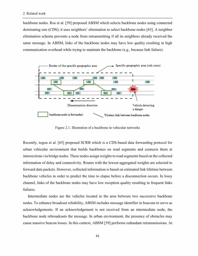
2. Related work .
41
backbone nodes. Ros et al. [59] proposed ABSM which selects backbone nodes using connected
dominating sets (CDS); it uses neighbors’ elimination to select backbone nodes [65]. A neighbor
elimination scheme prevents a node from retransmitting if all its neighbors already received the
same message. In ABSM, links of the backbone nodes may have low quality resulting in high
communication overhead while trying to maintain the backbone (e.g., because link failure).
Figure 2.1. Illustration of a backbone in vehicular networks
Recently, togou et al. [65] proposed SCRB which is a CDS-based data forwarding protocol for
urban vehicular environment that builds backbones on road segments and connects them at
intersections via bridge nodes. These nodes assign weights to road segments based on the collected
information of delay and connectivity. Routes with the lowest aggregated weights are selected to
forward data packets. However, collected information is based on estimated link lifetime between
backbone vehicles in order to predict the time to elapse before a disconnection occurs. In lossy
channel, links of the backbone nodes may have low reception quality resulting in frequent links
failures.
Intermediate nodes are the vehicles located in the area between two successive backbone
nodes. To enhance broadcast reliability, ABSM includes message identifier in beacons to serve as
acknowledgements. If an acknowledgement is not received from an intermediate node, the
backbone node rebroadcasts the message. In urban environment, the presence of obstacles may
cause massive beacon losses. In this context, ABSM [59] performs redundant retransmissions. At
2. Related work .
42
the other extreme, the backbone nodes that are responsible for message dissemination at each hop
may not be in farthest positions resulting in high number of communication hops. In this case,
both DBA-MAC and ABSM may achieve high communication delay (multi-hop time delay of
data transmission increases with communication hops) making them not suitable for safety
applications. Furthermore, over time, the backbone structure in DBA-MAC and ABSM must
change to match the changes in the network topology as vehicles move around (e.g., turn
right/left); this may result in high network overload (creation and maintenance of backbone
structure) degrading the network performance.
2.4.1.3. Delay-based schemes
In the case of DSRC-based safety applications, stringent delay requirements need to be
satisfied. To achieve lower delay, the node farthest from the source is generally selected to be the
forwarder. Several methods have been proposed to select the farthest vehicle as the next relaying
node (i.e., forwarder) in order to reduce hop count. Delay-based schemes (e.g., [64]
[60][61][62][63]) are designed to focus on fast data dissemination. UMB [60] divides the
transmission range into several sectors. The functions of forwarding and acknowledging the
message are assigned to only one vehicle located in the farthest non-empty sector. 3P3B [63]
iteratively partitions the communication range into small sectors. The partitioning mechanism
allows the farthest possible vehicle in the farthest sector from the sender node to perform
forwarding in order to increase the dissemination speed by reducing the number of forwarding
hops. In order to give emergency messages a higher access priority to the communication channel,
3P3B makes use of a mini distributed inter-frame space (DIFS) in medium access control (MAC)
sublayer In addition, it uses the RTB/CTB mechanism, which is similar to the request-to-
send/clear-to-send mechanism in the IEEE 802.11 standard, in the partitioning phase to cope with
the hidden terminal problem in multi-hop wireless networks. Messages, involved in collisions, are
retransmitted to improve reliability (i.e., packet reception rate). Sharifi et al. proposed DPS [66]
which computes the size of sectors (and thus the number) such that on average each sector contains
at least one vehicle. In the back area of the sender, the probability that a single vehicle exists in
each partition is equal or greater than a predefined threshold. In PAB [34], each node receiving a
packet determines the distance with respect to the sender. Then, it picks a waiting time inversely
proportional to the distance from the sender to the receiver. The farthest node is whose timer
expires first. PMBP [61] and ROFF [62] select the farthest forwarding node according to its
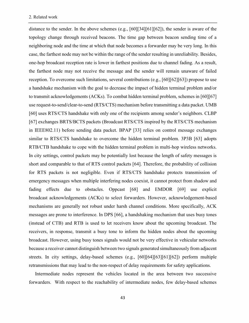
2. Related work .
43
distance to the sender. In the above schemes (e.g., [60][34][61][62]), the sender is aware of the
topology change through received beacons. The time gap between beacon sending time of a
neighboring node and the time at which that node becomes a forwarder may be very long. In this
case, the farthest node may not be within the range of the sender resulting in unreliability. Besides,
one-hop broadcast reception rate is lower in farthest positions due to channel fading. As a result,
the farthest node may not receive the message and the sender will remain unaware of failed
reception. To overcome such limitations, several contributions (e.g., [60][62][63]) propose to use
a handshake mechanism with the goal to decrease the impact of hidden terminal problem and/or
to transmit acknowledgements (ACKs). To combat hidden terminal problem, schemes in [60][67]
use request-to-send/clear-to-send (RTS/CTS) mechanism before transmitting a data packet. UMB
[60] uses RTS/CTS handshake with only one of the recipients among sender’s neighbors. CLBP
[67] exchanges BRTS/BCTS packets (Broadcast RTS/CTS inspired by the RTS/CTS mechanism
in IEEE802.11) before sending data packet. BPAP [33] relies on control message exchanges
similar to RTS/CTS handshake to overcome the hidden terminal problem. 3P3B [63] adopts
RTB/CTB handshake to cope with the hidden terminal problem in multi-hop wireless networks.
In city settings, control packets may be potentially lost because the length of safety messages is
short and comparable to that of RTS control packets [64]. Therefore, the probability of collision
for RTS packets is not negligible. Even if RTS/CTS handshake protects transmission of
emergency messages when multiple interfering nodes coexist, it cannot protect from shadow and
fading effects due to obstacles. Oppcast [68] and EMDOR [69] use explicit
broadcast acknowledgements (ACKs) to select forwarders. However, acknowledgement-based
mechanisms are generally not robust under harsh channel conditions. More specifically, ACK
messages are prone to interference. In DPS [66], a handshaking mechanism that uses busy tones
(instead of CTB) and RTB is used to let receivers know about the upcoming broadcast. The
receivers, in response, transmit a busy tone to inform the hidden nodes about the upcoming
broadcast. However, using busy tones signals would not be very effective in vehicular networks
because a receiver cannot distinguish between two signals generated simultaneously from adjacent
streets. In city settings, delay-based schemes (e.g., [60][64][63][61][62]) perform multiple
retransmissions that may lead to the non-respect of delay requirements for safety applications.
Intermediate nodes represent the vehicles located in the area between two successive
forwarders. With respect to the reachability of intermediate nodes, few delay-based schemes
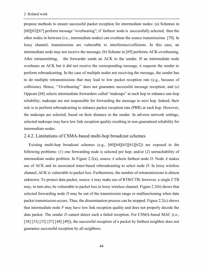
2. Related work .
44
propose methods to ensure successful packet reception for intermediate nodes: (a) Schemes in
[60][63][67] perform message “overhearing”; if farthest node is successfully selected, then the
other nodes in between (i.e., intermediate nodes) can overhear the source transmissions [70]. In
lossy channel, transmissions are vulnerable to interference/collisions. In this case, an
intermediate node may not receive the message; (b) Scheme in [69] performs ACK-overhearing.
After retransmitting, the forwarder sends an ACK to the sender. If an intermediate node
overhears an ACK but it did not receive the corresponding message, it requests the sender to
perform rebroadcasting. In the case of multiple nodes not receiving the message, the sender has
to do multiple retransmissions that may lead to low packet reception rate (e.g., because of
collisions). Hence, ‘’Overhearing’’ does not guarantee successful message reception; and (c)
Oppcast [68] selects intermediate forwarders called “makeups” at each hop to enhance one-hop
reliability; makeups are not responsible for forwarding the message to next hop. Indeed, their
role is to perform rebroadcasting to enhance packet reception rate (PRR) at each hop. However,
the makeups are selected, based on their distance to the sender. In adverse network settings,
selected makeups may have low link reception quality resulting in non-guaranteed reliability for
intermediate nodes.
2.4.2. Limitations of CSMA-based multi-hop broadcast schemes
Existing multi-hop broadcast schemes (e.g., [60][64][63][61][62]) are exposed to the
following problems: (1) one forwarding node is selected per hop; and/or (2) unreachability of
intermediate nodes problem. In Figure 2.2(a), source A selects farthest node D. Node A makes
use of ACK and its associated timer-based rebroadcasting to select node D. In lossy wireless
channel, ACK is vulnerable to packet loss. Furthermore, the number of retransmissions is almost
unknown. To protect data packet, source A may make use of RTB/CTB; however, a single CTB
may, in turn also, be vulnerable to packet loss in lossy wireless channel. Figure 2.2(b) shows that
selected forwarding node D may be out of the transmission range or malfunctioning when data
packet transmission occurs. Thus, the dissemination process can be stopped. Figure 2.2(c) shows
that intermediate node F may have low link reception quality and does not properly decode the
data packet. The sender D cannot detect such a failed reception. For CSMA-based MAC (i.e.,
[38] [33] [32] [37] [48] [49]), the successful reception of a packet by farthest neighbor does not
guarantee successful reception by all neighbors.
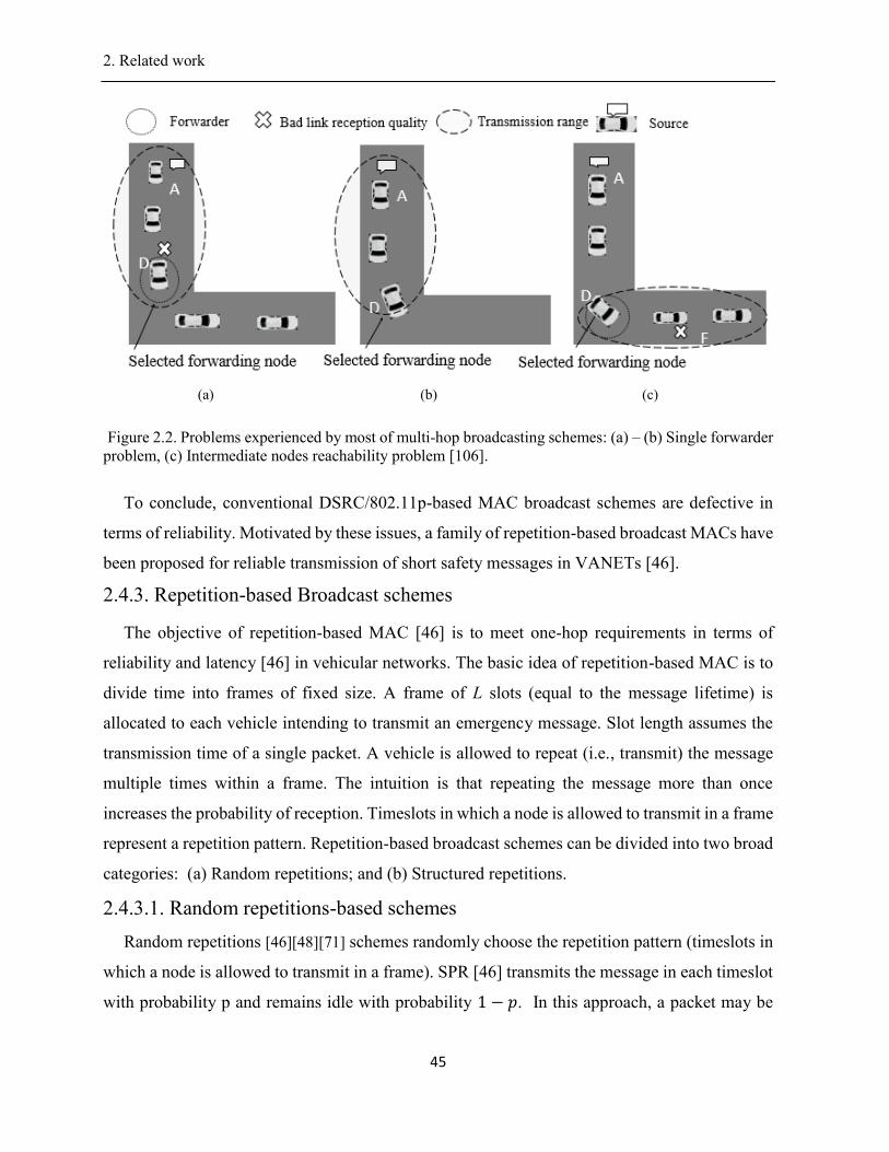
2. Related work .
45
(a) (b) (c)
Figure 2.2. Problems experienced by most of multi-hop broadcasting schemes: (a) – (b) Single forwarder
problem, (c) Intermediate nodes reachability problem [106].
To conclude, conventional DSRC/802.11p-based MAC broadcast schemes are defective in
terms of reliability. Motivated by these issues, a family of repetition-based broadcast MACs have
been proposed for reliable transmission of short safety messages in VANETs [46].
2.4.3. Repetition-based Broadcast schemes
The objective of repetition-based MAC [46] is to meet one-hop requirements in terms of
reliability and latency [46] in vehicular networks. The basic idea of repetition-based MAC is to
divide time into frames of fixed size. A frame of L slots (equal to the message lifetime) is
allocated to each vehicle intending to transmit an emergency message. Slot length assumes the
transmission time of a single packet. A vehicle is allowed to repeat (i.e., transmit) the message
multiple times within a frame. The intuition is that repeating the message more than once
increases the probability of reception. Timeslots in which a node is allowed to transmit in a frame
represent a repetition pattern. Repetition-based broadcast schemes can be divided into two broad
categories: (a) Random repetitions; and (b) Structured repetitions.
2.4.3.1. Random repetitions-based schemes
Random repetitions [46][48][71] schemes randomly choose the repetition pattern (timeslots in
which a node is allowed to transmit in a frame). SPR [46] transmits the message in each timeslot
with probability p and remains idle with probability 1 − 𝑝. In this approach, a packet may be
2. Related work .
46
transmitted L times or not transmitted at all. SFR [46] randomly chooses k slots out of the L slots.
It is proved in [46] that SFR is better than SPR and IEEE 802.11a in terms of reliability. FR-
EMD [71] extends SFR to multi-hop and adjusts the number of repetitions according to vehicles
density. However, it does not take into account signal propagation issues (i.e., slow-fading and
shadowing) caused by obstacles. RB-CD [48] focuses on reliable broadcasting for emergency
messages. The computation of the number of repetitions does not consider channel conditions.
Furthermore, RB-CD [48] does not combat hidden terminal problem. In situations where a large
number of transmissions happen, random access results in high packet loss rate. This is because
randomly choosing transmission slots incurs collisions/interference.
2.4.3.2. Structured repetitions-based schemes
Structured repetitions [72][73][49] obtain the transmission slots based on orthogonal codes. It
is shown in [72] that transmission/repetition patterns obtained from orthogonal codes [47]
perform better than SPR [46] and SFR [46] in terms of probability of transmission success and
delay. Unipolar orthogonal codes [47] represent binary sequences {0,1}, of length L, with small
cross-correlation 𝜆, where 𝜆 ∈ {0,1,2, … , 𝐿}. Obtaining repetition patterns from these codes
guarantees that maximum number of times that two vehicles simultaneously transmit is smaller
than the cross-correlation threshold. Schemes in [72] [73] focus on broadcast reliability of
periodic beacon messages using Unipolar Orthogonal Codes. The scheme in [72] does not
account for fast moving vehicles and highly dynamic wireless channel. In POC-MAC [73], the
distribution of repetition patterns, to vehicles, uses considerable channel resources (i.e., available
codes are acquired through message-passing) in high density network. In lossy channel, the
exchanged messages (message-passing between vehicles to update codes availability
information) can be lost. This may cause erroneous code assignment (i.e., two neighboring nodes
may allocate same code) resulting in unreliability. Furthermore, the authors [73] compute the
probability of reception success without taking into account the specific characteristics of V2V
communication, mainly signal propagation issues (e.g., multi-user interference and fading). This
may result in non-realistic reception probability estimation results (i.e., either overestimating or
underestimating success reception probability at different locations in the transmission range). In
addition, repetition-based MAC schemes [72][73] are not compatible with emerging
DSRC/802.11p [32]. CPF [49] extends POC-MAC [73] for multi-hop emergency message
dissemination in highway scenarios. In lossy wireless channel, selected forwarders may have bad
2. Related work .
47
link reception quality resulting in failed receptions; whatever the number of repetitions, if a
forwarder position is exposed to shadowing and multipath effects, the message dissemination
may fail resulting in unreliability. All of these schemes (e.g., [72][73][49]) use fixed number of
repetitions. Hence, they don’t guarantee high broadcast reliability in lossy channel. Indeed, if
fixed number of message repetitions is forwarded over a frame, they may be sending either too
few or too many packets. Too many packets lead to message overhead resulting in collisions and
too few packets lead to unreliability. Hence, an optimal number of repetitions must be determined
according to channel conditions.
2.4.4. Limitations of repetition-based MAC schemes
Structured repetition-based schemes are proposed to further enhance probability of successful
message reception, compared to random repetition schemes. Structured repetition-based schemes
make use of Uni-polar orthogonal codes (UPOC) to time-separate senders in a frame. Despite
their adequate performance in highway scenario, existing UPOC-based repetition schemes have
three major limitations in urban scenarios: (a) relying on a fixed small number of repetitions
cannot guarantee high reliability in time varying channel conditions (e.g., cannot be adapted to
the worst channel conditions). On the other hand, excessive repetitions might cause network
congestion; (b) they are not compatible with emerging IEEE DSRC/80.11p communication
standard (CSMA MAC); and (c) They use codes assignment mechanisms that rely on messages
passing between vehicles. In dense networks, these messages may be lost causing erroneous
codes assignment.
2.4.5. Summary of emergency message dissemination schemes
Existing CSMA-based multi-hop broadcasting have a series of reliability drawbacks in urban
environments (see Table 2.1). Forwarder selection and reachability of intermediate nodes are
major issues. Structured repetitions-based MAC schemes are based on time division of
transmitters in a frame. Yet, they have a number of limitations (see Table 2.1): (a) incompatibility
with CSMA/CA of DSRC/802.11p and (b) inability to ensure QoS in time varying channel
conditions.
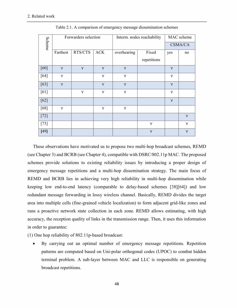
2. Related work .
48
Table 2.1. A comparison of emergency message dissemination schemes
Sch
eme
Forwarders selection Interm. nodes reachability MAC scheme
CSMA/CA
Farthest RTS/CTS ACK
overhearing Fixed
repetitions
yes no
[60] ⋎ ⋎ ⋎ ⋎ ⋎
[64] ⋎ ⋎ ⋎ ⋎
[63] ⋎ ⋎ ⋎ ⋎
[61] ⋎ ⋎ ⋎ ⋎
[62] ⋎
[68] ⋎ ⋎ ⋎
[72] ⋎
[73] ⋎ ⋎
[49] ⋎ ⋎
These observations have motivated us to propose two multi-hop broadcast schemes, REMD
(see Chapter 3) and BCRB (see Chapter 4), compatible with DSRC/802.11p MAC. The proposed
schemes provide solutions to existing reliability issues by introducing a proper design of
emergency message repetitions and a multi-hop dissemination strategy. The main focus of
REMD and BCRB lies in achieving very high reliability in multi-hop dissemination while
keeping low end-to-end latency (comparable to delay-based schemes [38][64]) and low
redundant message forwarding in lossy wireless channel. Basically, REMD divides the target
area into multiple cells (fine-grained vehicle localization) to form adjacent grid-like zones and
runs a proactive network state collection in each zone. REMD allows estimating, with high
accuracy, the reception quality of links in the transmission range. Then, it uses this information
in order to guarantee:
(1) One hop reliability of 802.11p-based broadcast:
By carrying out an optimal number of emergency message repetitions. Repetition
patterns are computed based on Uni-polar orthogonal codes (UPOC) to combat hidden
terminal problem. A sub-layer between MAC and LLC is responsible on generating
broadcast repetitions.
2. Related work .
49
(2) Multi-hop reliability:
By carefully selecting multiple forwarders and their positions, each single hop and
By employing a cooperative communication scheme that allows forwarders to
transmit the emergency message an optimal number of times with the objective to ensure
high reliability.
BCRB was proposed to improve the performance of REMD. The key contributions of BCRB can
be summarized as follows:
(1) Propose a training data collection phase that exploits periodic exchanged beacons to
collect packet collision information at each possible vehicle location.
(2) Propose a Bayesian networks based scheme to estimate, with good accuracy, link
reception quality, at different locations in the zone covered by the transmission range of
the sender; this estimation is based on beacons periodically generated by vehicles.
(3) Determine an optimal number of repetitions (i.e., message transmission) to
satisfy reliability requirements for each receiver in the area covered by the radio range of the
sender.
2.5. Internet Gateway Discovery
Reliability is an important requirement for an Internet access system. Gateway discovery
schemes use IEEE 802.11p multi-hop broadcast communication to establish paths to gateways
(discover available gateways and select one). Several gateway discovery schemes (i.e.,
[50][26][51][52]) have been proposed in the literature. These schemes can be classified into three
categories: (a) Proactive approaches; (b) Reactive approaches; and (c) Hybrid approaches.
2.5.1. Proactive approaches
In proactive approaches (e.g., [50][52]), gateways advertise themselves in the whole network
by periodically broadcasting advertisement messages. If a vehicle receives more than one
advertisement from gateways, it selects a best gateway. Criteria for selecting best gateway include
end-to-end delay and estimated connection lifetime between the vehicle and gateway. Bechler et
al. [50] proposed DRIVE where gateways use flooding to broadcast advertisement messages. The
gateway with the maximum route connection’s duration is selected (duration represents the time
elapsed before a connection breaks along the route; it is estimated using traffic density and
distance to gateway [50]). Flooding results in redundant transmissions of advertisement messages
2. Related work .
50
which can cause high control overhead. To reduce this overhead and to cope with the high mobility
of vehicles, Ngo et al. [52] proposed GD-ModCDS which uses virtual backbone construction
based on Connected Dominating Set (CDS). In GD-ModCDS, gateways employ the concept of
connected dominating set (CDS) to broadcast the advertisement message. Every vehicle is either
in CDS or adjacent to at least one node in CDS. If only vehicles in the CDS retransmit the
advertisement message once, all vehicles in the network can receive the advertisement message.
The CDS nodes are selected using route lifetime parameter. The route lifetime is the minimum of
the lifetimes of its constituent links; link lifetime is the time difference between link initiation and
link breakage/termination. Link lifetime is determined as a function of speeds and moving
directions of neighboring vehicles. In lossy wireless channel, selected CDS nodes may have bad
link reception quality resulting in failed receptions; whatever the link lifetime of the constituent
links, if a CDS node position is exposed to shadowing and multipath effects, the route with the
best route lifetime to the selected gateway may be unreliable leading to packet loss. The gateway
advertisement may fail resulting in unreliability. As gateways advertise messages in the whole
network, selected gateway (having maximum link lifetime) may not the closest one resulting in
higher communication hops. In [22], it has been proved that the number of breakages of a path
increases with the number of hops in the path.
2.5.2. Reactive approaches
In reactive approaches (e.g., [26][51][53]), gateway discovery is initiated by vehicles. Indeed,
vehicles (called requesters), that want Internet access, need to send solicitation messages in the
network for gateway discovery to request Internet connection. Namboodiri et al. [26] proposed
PBR for highway scenario. PBR exploits the predictable motion of vehicles on highways using
location and speed of vehicles. This information can be exploited to predict how long a route will
last between a vehicle requiring Internet connectivity and the gateway. Accurate prediction of
route lifetimes can significantly reduce the number of route failures. Amadou et al. [51][74]
proposed BCRPV to establish routes to gateways. The discovery protocol selects few forwarding
nodes, compared to [26], resulting in reduced overhead. Speed of neighboring vehicles is a main
parameter to predict lifetime of links between two vehicles. The gateway with the maximum
predicted route lifetime to the requestor is selected. In [53], the discovery process makes use of
predictable vehicle mobility, which is limited by traffic pattern and road layout. We conclude
that reactive schemes suffer from poor scalability in discovering gateways as all vehicles have to
2. Related work .
51
send requests. Existing schemes (e.g., [26][51][53][54]) make use of link stability metric, which
is based only on mobility metrics (e.g., relative motion between neighboring vehicles, speed,
etc.), to determine paths to gateways. In city settings, such a selected route can be broken
frequently owing signal conditions variation especially in the presence of obstacles. In [22], it
has been proved that the number of breakages of a path increases with the number of hops in the
path. Thus, the node centric view of the routes in [26][51][52][54][53] leads to frequent broken
routes especially in the case of lossy channel. Consequently, many packets can be dropped, and
the overhead due to route repairs or failure notifications significantly increases, leading to low
delivery ratios and high transmission delays of discovery messages. Thus, vehicles that are far
away from the mobile gateway transmission range will have limited or very poor Internet
connectivity.
2.5.3. Hybrid approaches
In hybrid approaches [75][54], gateways advertise themselves to their n-hop neighbors (𝑛 ≥
1); requesters send packets to find a gateway in these advertisement areas. A hybrid gateway
discovery approach is a combination of a reactive approach and a proactive approach. Thus, a
hybrid approach inherits almost same limitations of both reactive and proactive approaches.
Furthermore, the selection of advertisement areas depends on the dimension of the network. A
small advertisement area could result in high reactive overhead, and a large advertisement area
could result in high proactive overhead. In [54], the authors use the characteristics of vehicle
movements (e.g., speed and direction of movement) to predict the future behavior of vehicles,
and to select a route with the longest lifetime to connect to the wired network. In [75], the position
of the destination and the position of neighboring nodes are used to forward data without
establishing routes in the advertisement area. Any node that ensures progress toward the
destination can be used for forwarding. The forwarding decision is based on the position of
destination vehicle and position of one hop neighbors. However, the link to the selected node
may be unreliable in harsh network conditions leading to packet loss.
2.5.4 Limitations of Internet gateway discovery schemes
Urban environment poses several challenges that hinders establishing reliable communication
paths to gateways. Existing route discovery schemes are of three types: proactive, reactive, and
hybrid. Almost all of them are based on two main concepts (see Table 2.2):
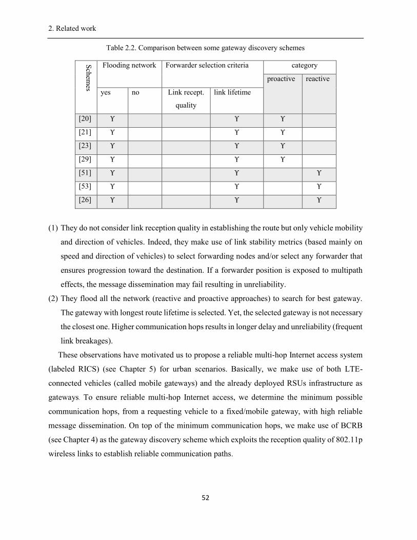
2. Related work .
52
Table 2.2. Comparison between some gateway discovery schemes
Sch
emes
Flooding network Forwarder selection criteria category
proactive reactive
yes no Link recept.
quality
link lifetime
[20] Υ Υ Υ
[21] Υ Υ Υ
[23] Υ Υ Υ
[29] Υ Υ Υ
[51] Υ Υ Υ
[53] Υ Υ Υ
[26] Υ Υ Υ
(1) They do not consider link reception quality in establishing the route but only vehicle mobility
and direction of vehicles. Indeed, they make use of link stability metrics (based mainly on
speed and direction of vehicles) to select forwarding nodes and/or select any forwarder that
ensures progression toward the destination. If a forwarder position is exposed to multipath
effects, the message dissemination may fail resulting in unreliability.
(2) They flood all the network (reactive and proactive approaches) to search for best gateway.
The gateway with longest route lifetime is selected. Yet, the selected gateway is not necessary
the closest one. Higher communication hops results in longer delay and unreliability (frequent
link breakages).
These observations have motivated us to propose a reliable multi-hop Internet access system
(labeled RICS) (see Chapter 5) for urban scenarios. Basically, we make use of both LTE-
connected vehicles (called mobile gateways) and the already deployed RSUs infrastructure as
gateways. To ensure reliable multi-hop Internet access, we determine the minimum possible
communication hops, from a requesting vehicle to a fixed/mobile gateway, with high reliable
message dissemination. On top of the minimum communication hops, we make use of BCRB
(see Chapter 4) as the gateway discovery scheme which exploits the reception quality of 802.11p
wireless links to establish reliable communication paths.
2. Related work .
53
2.6. Conclusion
In this chapter, we started by presenting flooding and challenges of multi-hop broadcasting in
urban vehicular network. Afterwards, we reviewed the different MAC schemes (CSMA-based
MAC and Repetitions-based MAC) proposed to address the issue of emergency message
dissemination. The discussion shows that reliability in DSRC/802.11p based multi-hop
broadcasting is still an unresolved issue. In the third part of this chapter, we described the various
Internet gateway discovery schemes proposed in the literature to allow a vehicle to connect to an
Internet gateway. The discussion shows proactive, reactive and hybrid approaches cannot
establish reliable multi-hop communication paths to gateways in lossy channel. The main reason
is that they do not consider wireless link reception quality in their operation and only rely on
speed and direction of vehicles. We will devote the rest of this thesis to our contributions that
aim at enhancing safety and infotainment applications in terms of reliability and delay. In Chapter
3, we detail the proposed reliable multi-hop broadcast scheme, called Reliable Emergency
Message Dissemination scheme (REMD), suitable for a wide range of vehicular safety
applications. In Chapter 4, we describe the new multi-hop broadcast scheme, called Bayesian
networks and unipolar orthogonal Code based Reliable multi-hop Broadcast (BCRB). Finally,
Chapter 5 describes the proposed Optimal Gateway Placement and Reliable Internet Access in
Urban Vehicular Environments, called reliable multi-hop Internet access system (called RICS)
for urban vehicular environments.
3. Reliable Emergency Message Dissemination Scheme for Urban Vehicular Networks .
54
Chapter 3
Reliable Emergency Message Dissemination for
Urban Vehicular Networks
Abstract
Vehicular safety applications based on DSRC/802.11p have strict reliability requirement
(greater than 0.99). However, it is difficult to achieve high reliability in wireless medium as the
transmission is vulnerable to packet collisions and interferences due to various wave propagation
issues, such as signal attenuation, noise and jitter. These effects are quite predominant in urban
vehicular networks in the presence of high rise buildings which makes communication in
vehicular networks quite unreliable. In this paper, we propose a reliable multi-hop broadcast
scheme, called Reliable Emergency Message Dissemination scheme (REMD), suitable for a wide
range of vehicular safety `applications. We aim to guarantee very high reliability (e.g., 99%) in
each hop, with low control overhead while keeping low end-to-end latency for time critical
applications. We divide a street into multiple cells to form grid-like zones. Each zone is assigned
a zero-correlated unipolar orthogonal code (UPOC) to combat hidden node problem. We apply
a proactive local state processing scheme, which makes use of periodic beacons, to accurately
estimate reception quality of 802.11p wireless link in each cell; then, we use this information to
determine optimal number of broadcast repetitions in order to satisfy the predefined reliability
requirements in each hop. In addition, to ensure reliability in multi-hop, we utilize cooperative
communication. Simulation results show that REMD achieves very high reliability in lossy
wireless channel. Furthermore, REMD reduces bandwidth consumption and satisfies latency
requirements for time-critical vehicular applications.
Key words: Reliability requirement, multi-hop broadcasting, emergency message, urban
vehicular networks, stochastic modeling.
Status: This article is submitted to IEEE Transactions on Intelligent Transportation Systems
2017; it is based on the following published paper:
Wiem Benrhaiem, Abdelhakim Hafid, and Pratap Kumar Sahu
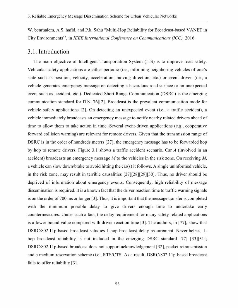
3. Reliable Emergency Message Dissemination Scheme for Urban Vehicular Networks .
55
W. benrhaiem, A.S. hafid, and P.k. Sahu “Multi-Hop Reliability for Broadcast-based VANET in
City Environments’’, in IEEE International Conference on Communications (ICC), 2016.
3.1. Introduction
The main objective of Intelligent Transportation System (ITS) is to improve road safety.
Vehicular safety applications are either periodic (i.e., informing neighboring vehicles of one’s
state such as position, velocity, acceleration, moving direction, etc.) or event driven (i.e., a
vehicle generates emergency message on detecting a hazardous road surface or an unexpected
event such as accident, etc.). Dedicated Short Range Communication (DSRC) is the emerging
communication standard for ITS [76][2]. Broadcast is the prevalent communication mode for
vehicle safety applications [2]. On detecting an unexpected event (i.e., a traffic accident), a
vehicle immediately broadcasts an emergency message to notify nearby related drivers ahead of
time to allow them to take action in time. Several event-driven applications (e.g., cooperative
forward collision warning) are relevant for remote drivers. Given that the transmission range of
DSRC is in the order of hundreds meters [27], the emergency message has to be forwarded hop
by hop to remote drivers. Figure 3.1 shows a traffic accident scenario. Car A (involved in an
accident) broadcasts an emergency message M to the vehicles in the risk zone. On receiving M,
a vehicle can slow down/brake to avoid hitting the car(s) it follows. A single uninformed vehicle,
in the risk zone, may result in terrible causalities [27][28][29][30]. Thus, no driver should be
deprived of information about emergency events. Consequently, high reliability of message
dissemination is required. It is a known fact that the driver reaction time to traffic warning signals
is on the order of 700 ms or longer [3]. Thus, it is important that the message transfer is completed
with the minimum possible delay to give drivers enough time to undertake early
countermeasures. Under such a fact, the delay requirement for many safety-related applications
is a lower bound value compared with driver reaction time [3]. The authors, in [77], show that
DSRC/802.11p-based broadcast satisfies 1-hop broadcast delay requirement. Nevertheless, 1-
hop broadcast reliability is not included in the emerging DSRC standard [77] [33][31];
DSRC/802.11p-based broadcast does not support acknowledgement [32], packet retransmission
and a medium reservation scheme (i.e., RTS/CTS. As a result, DSRC/802.11p-based broadcast
fails to offer reliability [3].
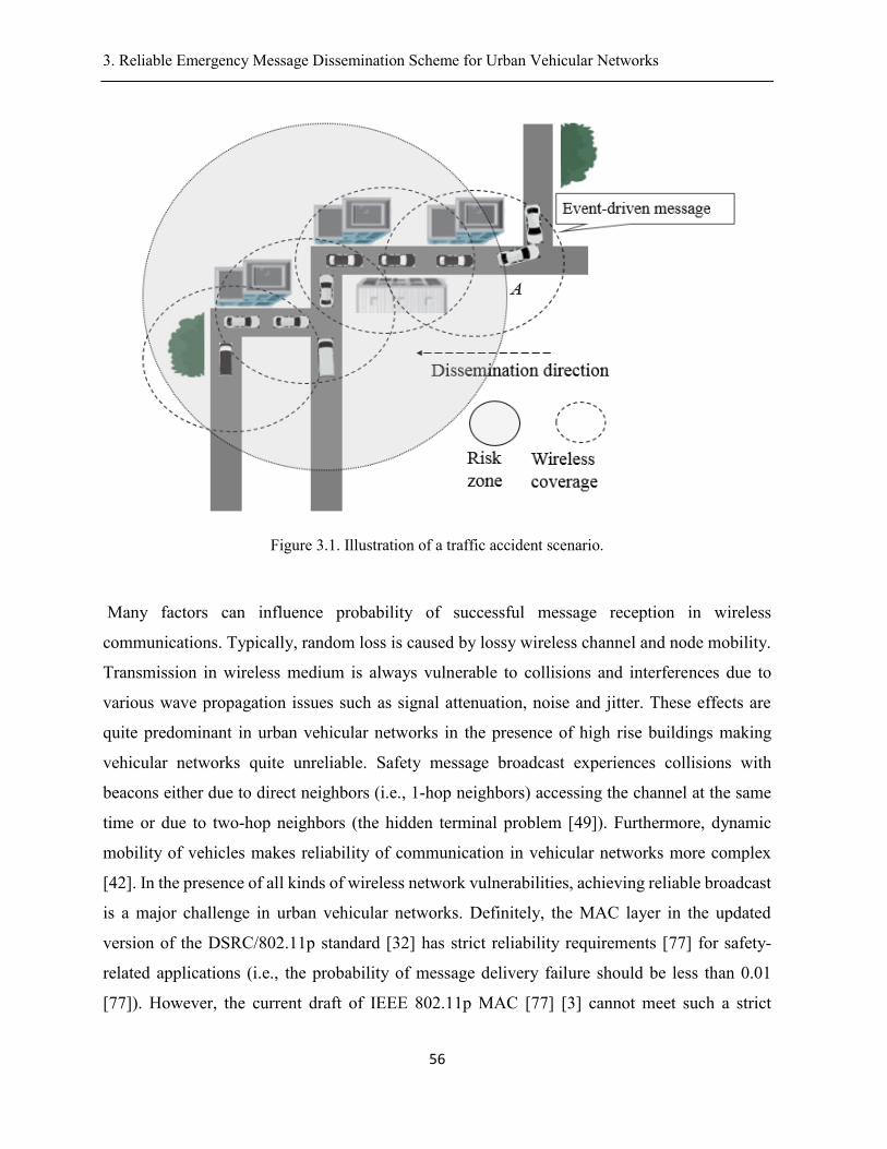
3. Reliable Emergency Message Dissemination Scheme for Urban Vehicular Networks .
56
Figure 3.1. Illustration of a traffic accident scenario.
Many factors can influence probability of successful message reception in wireless
communications. Typically, random loss is caused by lossy wireless channel and node mobility.
Transmission in wireless medium is always vulnerable to collisions and interferences due to
various wave propagation issues such as signal attenuation, noise and jitter. These effects are
quite predominant in urban vehicular networks in the presence of high rise buildings making
vehicular networks quite unreliable. Safety message broadcast experiences collisions with
beacons either due to direct neighbors (i.e., 1-hop neighbors) accessing the channel at the same
time or due to two-hop neighbors (the hidden terminal problem [49]). Furthermore, dynamic
mobility of vehicles makes reliability of communication in vehicular networks more complex
[42]. In the presence of all kinds of wireless network vulnerabilities, achieving reliable broadcast
is a major challenge in urban vehicular networks. Definitely, the MAC layer in the updated
version of the DSRC/802.11p standard [32] has strict reliability requirements [77] for safety-
related applications (i.e., the probability of message delivery failure should be less than 0.01
[77]). However, the current draft of IEEE 802.11p MAC [77] [3] cannot meet such a strict
3. Reliable Emergency Message Dissemination Scheme for Urban Vehicular Networks .
57
reliability requirements calling for new approaches for MAC layer design [79][80][81] with the
objective to guarantee broadcast reliability.
In multi-hop communication, the probability of successful message reception decreases with
the number of hops [36]. IEEE 802.11 MAC scheme does not offer any specific mechanism to
improve reliability in multi-hop, apart from the naïve flooding scheme [38]. However, such a
solution leads to the broadcast storm problem [82] resulting in unreliability (i.e., high packet loss)
and high latency [82]. Several multi-hop broadcast schemes have been proposed in the literature
[40][41][60][43]. In fast schemes [40][41], the emergency message is forwarded to selected
forwarders in quick successions. However, in case the forwarder has moved away or is
malfunctioning, the multi-hop communication would not be possible. Other schemes
[42][43][44], called efficient schemes, propose techniques to mitigate broadcast storm problem.
However, these schemes don’t consider MAC layer issues in their forwarding node selection
mechanism resulting in unreliable transmissions.
In [46] [83], resending the message multiple times in short intervals (time units) has been
introduced to meet the requirement in terms of one-hop broadcast reliability. The basic idea is to
repeat (i.e., transmit) the message multiple times within a frame in order to increase reception
probability; a frame consists of L time slots. This rebroadcasting method not only increases the
probability of reception but also meets latency requirements [46][83]. Random repetitions
schemes like SFR [46] randomly select k repetition slots out of L. It has been proved that
selecting k slots out of L increases the probability of successful message reception [42]. However,
SFR [46] results in low reception probability because of hidden terminal problem.
The authors in [49] proposed to compute structured repetitions pattern based on positive
orthogonal codes (POC) [62] (AKA unipolar orthogonal codes (UPOC)) in order to time separate
interfering nodes. An UPOC is a binary code of fixed length L, where cross-correlation between
any pair of code-words is less than a given threshold [62]. However, without evaluating the
channel condition, if the number of repetitions (of a given message) is fixed per time unit, it may
result in the transmission of either too few or too many packets. Too many packets lead to
overhead and collisions resulting in low probability of reception. Too few packets lead to
unreliability. In addition, existing structured repetitions based schemes [49][83][46] are not
compatible with the CSMA/CA mechanism of DSRC/802.11p.
3. Reliable Emergency Message Dissemination Scheme for Urban Vehicular Networks .
58
To overcome these limitations, we propose a reliable multi-hop broadcast scheme (REMD)
compatible with DSRC/802.11p MAC. We have already presented a first version of our scheme
in [31] and now present an extended and elaborated version. The main focus of this paper lies in
achieving very high reliability in multi-hop dissemination while keeping low end-to-end latency
(comparable to delay-based schemes [68] [60]) and low redundant message forwarding. REMD
ensures high reliability for emergency message dissemination in lossy wireless channel.
Basically, REMD divides the target area into multiple cells (fine-grained vehicle localization) to
form adjacent grid-like zones and runs a proactive network state collection in each zone. REMD
allows estimating, with high accuracy, the reception quality of links in the transmission range.
Then, it uses this information to determine optimal number of emergency message repetitions
(rebroadcasting) in order to satisfy the predefined reliability requirement in each hop. REMD
combats hidden terminals using Uni-Polar orthogonal codes (UPOC). REMD carefully selects
multiple forwarders and their positions in each hop. Then, it employs cooperative communication
among them as a way to reinforce achieving high reliability in each hop.
The remainder of this paper is organized as follows. Section 3.2 presents related work.
Sections 3.3 briefly overviews REMD. Sections 3.4-3.9 presents the components of REMD.
Section 3.10 evaluates, via simulations, the performance of REMD and compares it to existing
related schemes. Finally, Section 3.11 concludes the paper and presents future work.
3.2. Related work and Motivation
In this section, we review existing multi-hop broadcast schemes in vehicular networks. We
also discuss one-hop broadcast schemes that use message repetition to achieve reliability.
A. Multi-hop Broadcast schemes
Existing multi-hop broadcast schemes for vehicular networks can be divided into two
categories: (1) Efficient schemes and (2) Fast schemes.
1) Efficient schemes: These schemes aim at mitigating the broadcast storm problem in
vehicular networks. The main idea is to reduce the number of nodes rebroadcasting the message
without impacting reliability. We review two broad categories: (1) Probability-based [58] [43];
and (2) backbone-based [44] [42]. In [58], three probabilistic and timer-based broadcast
suppression techniques (weighted p-persistence, slotted 1-persistence, and slotted p-persistence)
are introduced. These techniques generate redundant retransmissions in dense networks resulting
3. Reliable Emergency Message Dissemination Scheme for Urban Vehicular Networks .
59
in large communication delay. Thus, the proposed techniques in [58] are not suitable for safety-
related applications. SAPF [43] regulates the rebroadcast probability adaptively based on the
vehicles speed. Proposed schemes in [58] [43] don’t consider MAC layer issues (i.e., the hidden
terminal problem, packet collisions, interference, link unreliability, etc.) which make forwarders
selection unreliable in lossy wireless channel (i.e., city settings). Backbone-based schemes (i.e.,
[42][44][65]) disseminate messages based on an already formed virtual backbone structure.
DBA-MAC [44] selects backbone nodes based on estimated lifetime of wireless connection
among vehicles. DBA-MAC achieves low packet reception rate in the presence of lossy wireless
channel. ABSM [42] makes use of acknowledgements (beacons include identifiers of the recently
received broadcast messages to serve as acknowledgments) to enhance reliability. If at least one
neighbor doesn’t acknowledge the message, the backbone node performs more retransmissions.
In dense networks, ABSM [42] performs redundant retransmissions due to increased packet
collisions. In city environment, the performance of wireless links is severely degraded due to
channel fading (i.e., surrounding buildings and mobility of nodes impact radio propagation)
resulting in weak connectivity between backbone nodes. Creation and maintenance of the
backbone structure (i.e., links of the backbone nodes) generate high communication overhead.
2) Fast schemes: Several schemes [60] [33] [40] [41] have been proposed for fast message
dissemination. The main idea is to reduce the number of hops resulting in fast message
propagation. To achieve this, these schemes select the farthest neighboring node from the sender
in the message propagation direction as the next relaying node. Several methods have been
proposed to elect the farthest forwarding node. UMB [60] divides the transmission range into
several sectors. After successfully receiving a message, a vehicle generates a black burst (channel
jamming signal) whose duration is proportional to the distance of its sector. Then, it computes a
waiting time inversely proportional to its distance. The vehicle located in the farthest sector is
elected as the forwarder. BPAB [33] is based on iterative binary partitioning to find the farthest
sector containing possible forwarder. In BPAB, a vehicle generates a black burst signal to
guarantee successful message reception at the farthest vehicle. UMBP [64] makes use of iterative
partition, mini-slots, and black-burst to select remote neighboring nodes. A single forwarding
node is chosen using asynchronous contention among remote neighboring nodes. However, using
black burst would not be very effective in vehicular networks; indeed, a receiver cannot
distinguish between two black bursts generated simultaneously from different road segments.
3. Reliable Emergency Message Dissemination Scheme for Urban Vehicular Networks .
60
3P3B [63] allows the farthest possible vehicle in the farthest sector from the sender node to
perform forwarding. In “Abiding Geocast” [40] and PAB [41], each node receiving a packet
determines the distance with respect to the sender. Then, it picks a waiting time inversely
proportional to the distance. The farthest node is whose time expires first; note that the sender is
aware of its neighbors through received beacons. However, the time gap between sender beacon
sending time of a node and the time at which that node becomes a forwarder may be very long.
In such situations, the forwarder may not be within the range of the sender. Thus, the sender
remains unaware of message dissemination and starts rebroadcasting. PMBP [61] selects the
farthest forwarding node according to its distance to the sender. Similarly, ROFF [62] selects the
farthest node using distance to the sender. However, it is a known fact that one hop broadcast
reception rate is lower in farthest positions due to channel fading [77]. As a result, existing
forwarding node selection methods (e.g., [64] [61] [63]) perform multiple timer-based
retransmissions which does not satisfy delay requirements of safety-related applications. CLBP
[67] selects a single forwarding node based on geographical locations, physical-layer channel
conditions, and moving velocities of vehicles. Before sending data packet, CLBP makes use of
BRTS/BCTS packets to prevent hidden terminal problem. However, a single BRTS packet is
vulnerable to interference in a city scenario. To ensure reliable message delivery to forwarder,
the latter sends an acknowledgement (ACK) frame back to the sender. However,
acknowledgement (ACK) mechanism is generally not robust under harsh channel conditions.
More specifically, ACK messages are prone to interferences. In addition, in most of
aforementioned schemes (i.e., [61] [62] [63][64]), a single selected forwarding node may change
direction or be malfunctioning. In such a situation, the proposed schemes will not properly work.
They suffer from unreachability of intermediate nodes (i.e., located in the area between two
successive forwarding nodes) problem; these nodes perform overhearing to receive messages.
The overhearing approach does not guarantee successful message reception. As a result,
broadcast reception rate is low in lossy wireless channel. In the literature, few schemes (i.e., [68]
[45]) have proposed solutions to improve reliability of intermediate nodes. Oppcast [68] selects
farthest possible neighboring node based on acknowledgements (ACK) and retransmissions to
forward the message to next hop. To improve packet reception ratio for intermediate nodes,
Oppcast elects ‘makeups’ (intermediate forwarders). The makeups rebroadcast the message to
enhance the packet reception rate PRR in each one-hop area. However, the ‘makeups’ are
3. Reliable Emergency Message Dissemination Scheme for Urban Vehicular Networks .
61
selected, based on their distance to the sender. In adverse network conditions, selected makeups
may have low reception quality resulting in packet loss. Oppcast records low PRR for
intermediate nodes. EMDOR [45] selects a single forwarding node each hop to disseminate
message to next hops. The selected forwarding node transmits an ACK message on behalf of
other receiving nodes. EMDOR improves the broadcast reliability of intermediate nodes by
allowing them to overhear an ACK packet; if a node overhears an ACK, but has not received the
corresponding message, the node considers that the emergency message is lost and requests the
selected node to perform rebroadcasting. The retransmission overhead could be very large. This
is because different nodes could lose different packets and therefore the sender node has to
retransmit all these lost packets. To conclude, fast schemes are more concerned by delay more
than reliability. Consequently, emergency messages are received with minimum latency at the
cost of lower reliability.
Existing multi-hop broadcast schemes (i.e., [60] [33] [40] [41] [61] [62]) are exposed to the
following problems: (1) one forwarding node is selected per hop; and/or (2) unreachability of
intermediate nodes problem. In Figure 3.2(a), source A selects farthest node D. Node A makes
use of ACK and its associated timer-based rebroadcasting to select node D. In lossy wireless
channel, ACK is vulnerable to packet loss. Furthermore, the number of retransmissions is almost
unknown. To protect data packet, source A may make use of RTB/CTB; however, a single CTB
may, in turn also, be vulnerable to packet loss in lossy wireless channel. Figure 3.2(b) shows that
selected forwarding node D may be out of the transmission range or malfunctioning when data
packet transmission occurs. Thus, the dissemination process can be stopped. Figure 3.2(c) shows
that intermediate node F may have low link reception quality and does not properly decode the
data packet. The sender D cannot detect such a failed reception.
For CSMA-based MAC (i.e., [60] [33] [40] [41] [61] [62]), the successful reception of a
packet by the farthest neighbor does not guarantee the successful reception by all other neighbors.
Recently a family of repetition-based MAC protocols have been proposed for the one-hop
broadcasting of safety messages in vehicular networks.
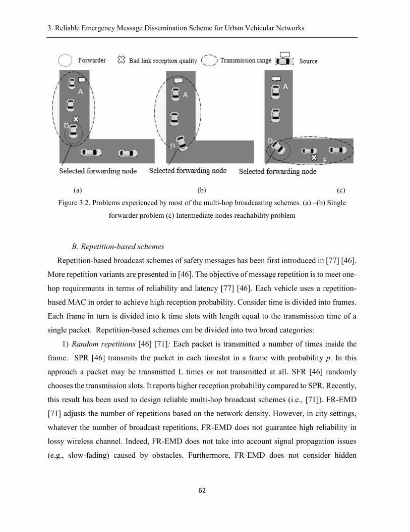
3. Reliable Emergency Message Dissemination Scheme for Urban Vehicular Networks .
62
(a) (b) (c)
Figure 3.2. Problems experienced by most of the multi-hop broadcasting schemes. (a) –(b) Single
forwarder problem (c) Intermediate nodes reachability problem
B. Repetition-based schemes
Repetition-based broadcast schemes of safety messages has been first introduced in [77] [46].
More repetition variants are presented in [46]. The objective of message repetition is to meet one-
hop requirements in terms of reliability and latency [77] [46]. Each vehicle uses a repetition-
based MAC in order to achieve high reception probability. Consider time is divided into frames.
Each frame in turn is divided into k time slots with length equal to the transmission time of a
single packet. Repetition-based schemes can be divided into two broad categories:
1) Random repetitions [46] [71]: Each packet is transmitted a number of times inside the
frame. SPR [46] transmits the packet in each timeslot in a frame with probability p. In this
approach a packet may be transmitted L times or not transmitted at all. SFR [46] randomly
chooses the transmission slots. It reports higher reception probability compared to SPR. Recently,
this result has been used to design reliable multi-hop broadcast schemes (i.e., [71]). FR-EMD
[71] adjusts the number of repetitions based on the network density. However, in city settings,
whatever the number of broadcast repetitions, FR-EMD does not guarantee high reliability in
lossy wireless channel. Indeed, FR-EMD does not take into account signal propagation issues
(e.g., slow-fading) caused by obstacles. Furthermore, FR-EMD does not consider hidden
3. Reliable Emergency Message Dissemination Scheme for Urban Vehicular Networks .
63
terminal problem. In situations of large number of transmissions, randomly selecting repetition
slots may result in high packet loss rate (i.e., collisions/interference).
2) Structured repetitions [49][73]: Transmission/repetition patterns (timeslots in which a
node is allowed to transmit in a frame) are computed based on positive orthogonal codes (POC),
known as unipolar orthogonal codes (UPOC). An UPOC [84] represents a binary sequence {0,1}
with small cross-correlation, where cross-correlation between any pair of code-words is less than
a given threshold [84]. In POC-MAC [73], the distribution of repetition patterns to nodes uses
considerable channel resources (i.e., available codes are acquired through message-passing) in
high density networks. In lossy channel, the exchanged messages (message-passing between
vehicles to update codes availability information) can be lost. This may result in erroneous code
assignment (i.e., two neighboring nodes may allocate same code) resulting in unreliability.
Furthermore, the authors compute the probability of successful transmission without taking into
account signal propagation issues. CPF [49] extends POC-MAC [73] for multi-hop emergency
message dissemination in highway scenarios. In lossy wireless channel, selected forwarders may
have bad link reception quality resulting in failed reception; whatever the number of repetitions,
if a forwarder position is exposed to shadowing and multipath effects, the message dissemination
will be stopped resulting in unreliability. CPF doesn’t guarantee high broadcast reliability in
lossy channel. Indeed, if fixed number of message repetitions is forwarded over a frame, they
may be sending either too few or too many packets.
In addition, structured repetition-based schemes [49][73] are not compatible with emerging
DSRC/802.11p. In this paper, REMD provides a solution to existing reliability issues, by
introducing a proper design of emergency message repetitions and a multi-hop dissemination
strategy compatible with DSRC/802.11p. More specifically, REMD allows
estimating/predicting, with high accuracy, the link reception quality. Then, it uses this
information in order to guarantee:
(1) One hop reliability of 802.11p-based broadcast:
By carrying out an optimal number of emergency message repetitions. Repetition patterns
are computed based on Uni-polar orthogonal codes (UPOC) to combat hidden terminal
problem.
(2) Multi-hop reliability:
3. Reliable Emergency Message Dissemination Scheme for Urban Vehicular Networks .
64
By carefully selecting multiple forwarders and their positions, each single hop.
By employing a cooperative communication scheme that allows forwarders to retransmit
the emergency message an optimal number of times with the objective of ensuring high
retransmission reliability.
3.3. REMD: An Overview
REMD is designed to disseminate emergency messages with very high reliability in urban
vehicular network. The main idea of REMD is to guarantee broadcast reliability (e.g., 𝑟𝑡ℎ=99%))
[27] at each hop by performing an optimal number of broadcast repetitions. Basically, REMD
estimates, with high accuracy, the reception quality of wireless link in the transmission range Tr.
Then, it uses this information to compute an optimal number of message repetitions and to select
multiple forwarders and their positions at each hop. The forwarders of each hop perform
cooperative communication to reinforce achieving high broadcast reliability.
A. Assumptions
We assume that (1) vehicles are moving on urban streets; a scenario where a source node with
a generic emergency message M that requires multi-hop transmission is intended for all nearby
vehicles in a geographical area; (2) vehicles are equipped with Global Positioning System (GPS)
and digital road maps; (3) vehicles are equipped with IEEE 802.11p [2] wireless technology and
computation capabilities; (4) obstacles (e.g., buildings, moving vehicles) exist; they impact
communication among vehicles; and (5) the factors causing failures of message transmissions
are temporary or intermittent (e.g., failure of 802.11p/GPS in a vehicle is not considered).
B. Network model and definitions
In the following, we present the definitions of the relevant terms used to describe REMD (See
Figure 3.3(a)).
Source node: It defines the vehicle that detects an unexpected event.
Target area: It defines the geographical area that includes all vehicles approaching/driving,
towards the source, that are intended recipients of the emergency message generated by the
source node
Segment: It defines the area between two road intersections.
Zone: It defines a static portion of the segment whose length is same as the transmission range
of a vehicle. Based on its length, a road segment is divided into a number of zones.
3. Reliable Emergency Message Dissemination Scheme for Urban Vehicular Networks .
65
Cell: It defines a static partition of a zone with predefined length (e.g., length of a Car 𝑦= ~
6 meters [104]). A cell represents a possible vehicle position (a fine-grain localization of
vehicles). Assuming the lowest speed in the city is equal to 10 Km/hour, the minimum distance
between two vehicles is 10000∗2
3600≅ 5.55meters. Thus, there will be either 1 vehicle or no vehicle
in each cell. In each zone, cells are identified/numbered 1, 2, 3, etc.
Transit time: It defines the time interval that a vehicle takes to transit a cell (a vehicle
position). If Ve is the vehicle velocity, the transit delay T is computed as follows:
𝑇 =6
𝑉𝑒 (1)
Regular vehicle: It defines a passing vehicle. During T, such a vehicle records cell
information. Then, it includes this information in its next beacon. We use the term regular vehicle
or vehicle interchangeably to denote a passing vehicle.
Coordinator: It defines a vehicle located around the center of a zone to continuously process
received beacons of vehicles in the effective zone (i.e., the current zone). There exists a
coordinator per zone.
Coordination packet (CP): It defines a periodic packet transmitted by the coordinator. The
coordinator transmits periodic CPs instead of periodic beacons (See Figure 3.3(b)). CP includes
the status information of the coordinator (position, velocity, direction, etc.) together with
information it processed. The transmission power of CP is two times the beacon’s one.
Sender: It defines the current broadcast node (a node that intends to transmit the emergency
message). The source is a sender when it first broadcasts the emergency message.
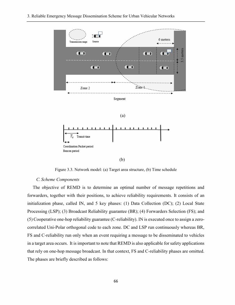
3. Reliable Emergency Message Dissemination Scheme for Urban Vehicular Networks .
66
(a)
(b)
Figure 3.3. Network model: (a) Target area structure, (b) Time schedule
C. Scheme Components
The objective of REMD is to determine an optimal number of message repetitions and
forwarders, together with their positions, to achieve reliability requirements. It consists of an
initialization phase, called IN, and 5 key phases: (1) Data Collection (DC); (2) Local State
Processing (LSP); (3) Broadcast Reliability guarantee (BR); (4) Forwarders Selection (FS); and
(5) Cooperative one-hop reliability guarantee (C-reliability). IN is executed once to assign a zero-
correlated Uni-Polar orthogonal code to each zone. DC and LSP run continuously whereas BR,
FS and C-reliability run only when an event requiring a message to be disseminated to vehicles
in a target area occurs. It is important to note that REMD is also applicable for safety applications
that rely on one-hop message broadcast. In that context, FS and C-reliability phases are omitted.
The phases are briefly described as follows:
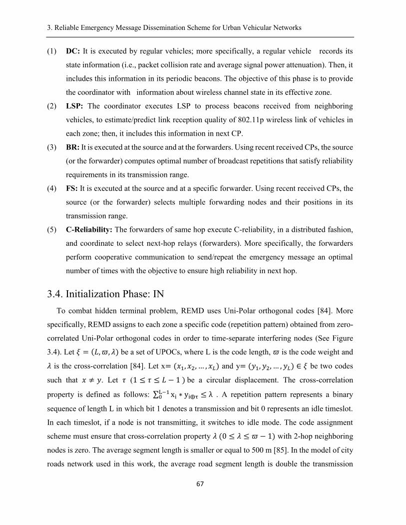
3. Reliable Emergency Message Dissemination Scheme for Urban Vehicular Networks .
67
(1) DC: It is executed by regular vehicles; more specifically, a regular vehicle records its
state information (i.e., packet collision rate and average signal power attenuation). Then, it
includes this information in its periodic beacons. The objective of this phase is to provide
the coordinator with information about wireless channel state in its effective zone.
(2) LSP: The coordinator executes LSP to process beacons received from neighboring
vehicles, to estimate/predict link reception quality of 802.11p wireless link of vehicles in
each zone; then, it includes this information in next CP.
(3) BR: It is executed at the source and at the forwarders. Using recent received CPs, the source
(or the forwarder) computes optimal number of broadcast repetitions that satisfy reliability
requirements in its transmission range.
(4) FS: It is executed at the source and at a specific forwarder. Using recent received CPs, the
source (or the forwarder) selects multiple forwarding nodes and their positions in its
transmission range.
(5) C-Reliability: The forwarders of same hop execute C-reliability, in a distributed fashion,
and coordinate to select next-hop relays (forwarders). More specifically, the forwarders
perform cooperative communication to send/repeat the emergency message an optimal
number of times with the objective to ensure high reliability in next hop.
3.4. Initialization Phase: IN
To combat hidden terminal problem, REMD uses Uni-Polar orthogonal codes [84]. More
specifically, REMD assigns to each zone a specific code (repetition pattern) obtained from zero-
correlated Uni-Polar orthogonal codes in order to time-separate interfering nodes (See Figure
3.4). Let 𝜉 = (𝐿,𝜛, 𝜆) be a set of UPOCs, where L is the code length, 𝜛 is the code weight and
𝜆 is the cross-correlation [84]. Let x= (𝑥1, 𝑥2, … , 𝑥𝐿) and y= (𝑦1, 𝑦2, … , 𝑦𝐿) ∈ 𝜉 be two codes
such that 𝑥 ≠ 𝑦. Let 𝜏 (1 ≤ 𝜏 ≤ 𝐿 − 1)be a circular displacement. The cross-correlation
property is defined as follows: ∑ xi ∗ yi⨁τL−10 ≤ λ. A repetition pattern represents a binary
sequence of length L in which bit 1 denotes a transmission and bit 0 represents an idle timeslot.
In each timeslot, if a node is not transmitting, it switches to idle mode. The code assignment
scheme must ensure that cross-correlation property 𝜆(0 ≤ 𝜆 ≤ 𝜛 − 1) with 2-hop neighboring
nodes is zero. The average segment length is smaller or equal to 500 m [85]. In the model of city
roads network used in this work, the average road segment length is double the transmission
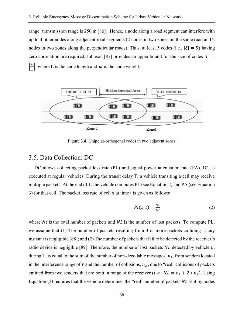
3. Reliable Emergency Message Dissemination Scheme for Urban Vehicular Networks .
68
range (transmission range is 250 m [86]). Hence, a node along a road segment can interfere with
up to 4 other nodes along adjacent road segments (2 nodes in two zones on the same road and 2
nodes in two zones along the perpendicular roads). Thus, at least 5 codes (i.e., |𝜉| = 5) having
zero correlation are required. Johnson [87] provides an upper bound for the size of codes |𝜉| =
⌊𝐿
𝜛⌋, where L is the code length and 𝝕 is the code weight.
Figure 3.4. Unipolar-orthogonal codes in two adjacent zones
3.5. Data Collection: DC
DC allows collecting packet loss rate (PL) and signal power attenuation rate (PA). DC is
executed at regular vehicles. During the transit delay T, a vehicle transiting a cell may receive
multiple packets. At the end of T, the vehicle computes PL (see Equation 2) and PA (see Equation
3) for that cell. The packet loss rate of cell x at time t is given as follows:
𝑃𝑙(𝑥, 𝑡) =𝑁𝐿
𝑁𝑡 (2)
where 𝑁𝑡isthe total number of packets and 𝑁𝐿isthe number of lost packets. To compute PL,
we assume that (1) The number of packets resulting from 3 or more packets colliding at any
instant t is negligible [88]; and (2) The number of packets that fail to be detected by the receiver’s
radio device is negligible [89]. Therefore, the number of lost packets 𝑁𝐿 detected by vehicle 𝑣,
during T, is equal to the sum of the number of non-decodable messages, 𝑛1, from senders located
in the interference range of 𝑣 and the number of collisions, 𝑛2, due to “real” collisions of packets
emitted from two senders that are both in range of the receiver (𝑖. 𝑒. , 𝑁𝐿 = 𝑛1 + 2 ∗ 𝑛2). Using
Equation (2) requires that the vehicle determines the “real” number of packets𝑁𝑡 sent by nodes
3. Reliable Emergency Message Dissemination Scheme for Urban Vehicular Networks .
69
in range or in interference range; the “real” number of packets includes packets that didn’t reach
the vehicle; in practice, a receiver is unable to record such information. The “real” number of
packets𝑁𝑡 is equal to the sum of the number of lost packets 𝑁𝐿 and the number of successfully
received packets 𝑁𝑟 (𝑖. 𝑒, .𝑁𝑡 = 𝑁𝐿 + 𝑁𝑟).The signal power attenuation rate PA of cell x at
time t is expressed as follows:
𝑃𝐴(𝑥, 𝑡) =1
𝑁𝑟∗ ∑ (
𝑋0(𝑑𝑖)
𝑇𝑥)𝑖=𝑁𝑟
𝑖=1 (3)
where 𝑑𝑖 is the distance to neighbor i,, 𝑋0(𝑑𝑖) is the power attenuation rate of a packet sent by
neighbor i, and 𝑇𝑥 is the transmitted signal power. Upon a successful reception of a packet, the
vehicle records the packet’s received signal strength indicator (RSSI) and its transmitted power
𝑇𝑥. It is worth noting that signal power attenuation, reception power and transmitted power are
only available for successfully received packets. In a realistic channel model, like Rayleigh, the
RSSI value at distance d from the transmitter is given by:
𝑅𝑆𝑆𝐼(𝑑) = 𝑇𝑥 − 𝐿𝑜𝑠(𝑑0) − 10 ∗ 𝜌 ∗ 𝑙𝑜𝑔10 (𝑑
𝑑0) + 𝑋0 (4)
where 𝑇𝑥 is the transmitted power in decibel (DB), 𝐿𝑜𝑠(𝑑0) is the path loss at a reference distance
(i.e., 𝑑0), 𝜌 is the path loss exponent and 𝑋0 denotes the signal attenuation in decibel. 𝑋0 is
modeled as random variable with Rayleigh distribution [90]. The value of 𝜌 can be set depending
on the propagation environment [90]. Our objective is to extract the value of the attenuation effect
𝑋0 from the received RSSI value. To achieve this, we consider one sender and one receiver,
spaced by m meters. The transmitter emits only one packet to be exposed to only fading and path
loss effect (i.e.,𝑋0 = 0). In this case, the receiver records signal power degradation (𝑇𝑥 − 𝑅𝑆𝑆𝐼
). Then, it calculates the average attenuation per meter (e.g., for d=20 meters and0.08𝑑𝑏; we
obtain signal power degradation rate 𝛼 = ~0.004𝑑𝑏/𝑚𝑒𝑡𝑒𝑟). Thus, the receiver is able to
extract 𝑋0 from RSSI (i.e., 𝑋0(𝑑) = 𝑅𝑆𝑆𝐼(𝑑) − 𝛼 ∗ 𝑑). At the end of T, regular vehicle includes
PL and PA in its next beacon.
3. Reliable Emergency Message Dissemination Scheme for Urban Vehicular Networks .
70
3.6. Local State Processing: LSP
This phase estimates link reception quality 𝑄in the transmission range. LSP is executed at the
coordinator node. The coordinator acts as a zone manager. It is in charge of processing exchanged
beacons. Indeed, the zone manager provides a source node with data corresponding to its range.
A coordinator is chosen dynamically through exchange of beacons. To select a coordinator, we
introduce a status flag in beacons, which, if set, represents a coordinator vehicle; otherwise, it
represents a regular vehicle. We define start coordination position S-p as one-quarter of the
transmission range away from the beginning of the zone and the last coordination position L-p
as three-quarter of the transmission range away from the beginning of the zone. If a vehicle finds
itself as the closest vehicle to the position S-p, it sets its status to coordinator; a flag is included
in periodic beacons to represent the status of a vehicle (i.e., coordinator or regular vehicle). Upon
reaching the position L-p, it resets its status (i.e., becomes regular vehicle) and allows another
vehicle located in S-p (or nearby) to be the zone manager. At any time, there is only one
coordinator per zone. Upon receipt of a beacon from a vehicle located in cell x at time t, the
coordinator extracts (1) 𝑃𝐿(𝑥, 𝑡) to measure the quality of wireless link in cell x (see Equation
5); and (2) 𝑃𝐴(𝑥, 𝑡) to compute an equivalent packet loss rate 𝑒𝑃𝐿(𝑥, 𝑡) (see Equation 6). Let
us analyze the variation, over time, of average attenuation (PA) and packet loss rate (PR) for cell
‘A’ (see Figure 3.5). By using 4th order polynomial curve fitting [91], we show that PA and PL
have similar variations (see Figure 3.5); they have linear correlation. We extract the conversion
ratio 𝜏 (correlation coefficient) that represents the average attenuation to the average packet loss
over a period of time. Therefore, the reception quality of 802.11p wireless link Q(x, t) at time t
can be expressed as follows:
𝑄(𝑥, 𝑡) = 1 − 𝑃𝐿(𝑥, 𝑡) (5)
In case of controlled channel condition, reported PL values may be equal to zero. Therefore, the
reception quality of 802.11p wireless link Q(x, t) at time t can be expressed as follows:
𝑄(𝑥, 𝑡) = 1 − 𝑒𝑃𝐿(𝑥, 𝑡) = 1 − 𝜏 ∗ 𝑃𝐴(𝑥, 𝑡) (6)
Link reception quality 𝑄(𝑥, 𝑡)changes over time due to the dynamic nature of vehicular
networks; thus, if the source node uses reception quality measured at t1, by the coordinator, to
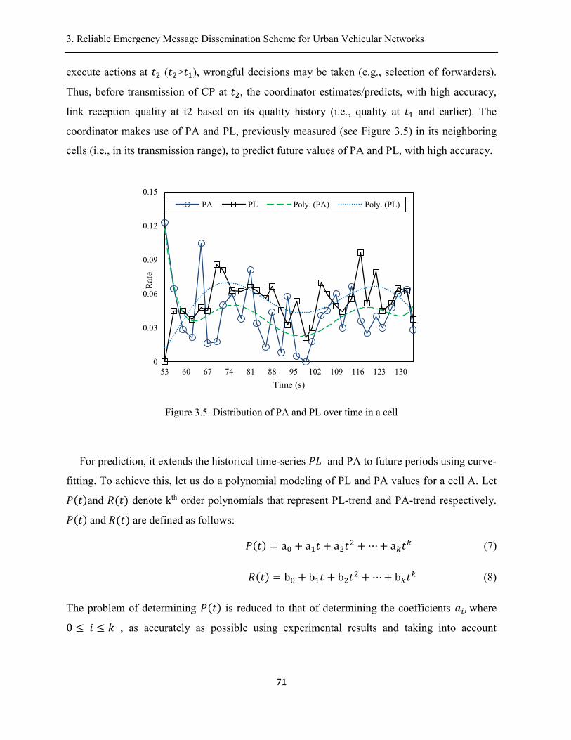
3. Reliable Emergency Message Dissemination Scheme for Urban Vehicular Networks .
71
execute actions at 𝑡2 (𝑡2>𝑡1), wrongful decisions may be taken (e.g., selection of forwarders).
Thus, before transmission of CP at 𝑡2, the coordinator estimates/predicts, with high accuracy,
link reception quality at t2 based on its quality history (i.e., quality at 𝑡1 and earlier). The
coordinator makes use of PA and PL, previously measured (see Figure 3.5) in its neighboring
cells (i.e., in its transmission range), to predict future values of PA and PL, with high accuracy.
Figure 3.5. Distribution of PA and PL over time in a cell
For prediction, it extends the historical time-series 𝑃𝐿 and PA to future periods using curve-
fitting. To achieve this, let us do a polynomial modeling of PL and PA values for a cell A. Let
𝑃(𝑡)and 𝑅(𝑡) denote kth order polynomials that represent PL-trend and PA-trend respectively.
𝑃(𝑡)and𝑅(𝑡) are defined as follows:
𝑃(𝑡) = a0 + a1𝑡 + a2𝑡2 + ⋯+ a𝑘𝑡
𝑘 (7)
𝑅(𝑡) = b0 + b1𝑡 + b2𝑡2 + ⋯+ b𝑘𝑡
𝑘 (8)
The problem of determining 𝑃(𝑡) is reduced to that of determining the coefficients 𝑎𝑖,where
0 ≤ 𝑖 ≤ 𝑘 , as accurately as possible using experimental results and taking into account
0
0.03
0.06
0.09
0.12
0.15
53 60 67 74 81 88 95 102 109 116 123 130
Rat
e
Time (s)
PA PL Poly. (PA) Poly. (PL)
3. Reliable Emergency Message Dissemination Scheme for Urban Vehicular Networks .
72
experimental errors. Quantifying the error for the polynomial trend using the least squares
approach is as follows:
𝑒𝑟𝑟 = ∑(𝑑𝑖)2 = ∑(𝑃𝐿(𝑡𝑖) − 𝑃(𝑡𝑖))
2 (9)
Note that it is particularly difficult to accurately estimate/predict the channel condition in
vehicular networks due to the frequently changing network environment [92]. Although there are
some limitations for the polynomial modeling based estimation, we can minimize the error
(Equation (9)). Similarly, coefficients in Equation (8) can be estimated. The approximation of
PL and PA variations are then 𝑃(𝑡) and𝑄(𝑡). Therefore, the coordinator sets a local state map
(LSM), and includes it in its next CP. LSM consists of link reception quality 𝑄(𝑥, 𝑡) of vehicles
in the effective zone.
3.7. Broadcast Reliability: BR
This phase allows guaranteeing predefined reliability 𝑟𝑡ℎin transmission range. To achieve
this, the vehicle rapidly repeats the message an optimal number of times, using the repetition
pattern of its effective zone, with the objective to enhance reception probability per-receiver.
More specifically, we consider a useful message lifetime T whose value is smaller than human
reaction time; the vehicle repeats broadcasting the packet multiple times only within T. Let 𝜏 be
the time needed to perform one repetition (𝜏 = 1 time slot). The transmitter evenly splits the
lifetime into L time slots, where𝐿 = ⌊𝑇
𝜏⌋. Each repetition of the message is a new packet. Cell
transit time 𝑇𝑠 ranges between 0.2 s and 0.4 s while message lifetime T is less than 0.5s. Link
reception quality 𝑄(𝑥, 𝑡) represents reception probability per slot.
𝑝(𝑥) = 𝑄(𝑥, 𝑡)(10)
During T, the sender performs n repetitions. Excessive repetitions might cause congestion
leading to collisions [48]. Therefore, an optimal number of repetitions 𝑛𝑜𝑝𝑡 must be determined.
Let Ng be the number of neighbors in transmission range, 𝑡𝑘 (1 ≤ 𝑘 ≤ 𝐿)be a random variable
that indicates that k time slots are picked (i.e., k repetitions are performed) and 𝑋𝑖(0 ≤ 𝑖 ≤ 𝑁𝑔)
be a random variable taking values 0 and 1. 𝑋𝑖follows a Bernoulli random variable 𝑋𝑖~𝛽(𝑝(𝑥))
3. Reliable Emergency Message Dissemination Scheme for Urban Vehicular Networks .
73
with reception probability 𝑝𝑖, associated with receiver 𝑖. The probability mass function (p.m.f)
of 𝑋𝑖 is shown in Eq,(11). Let 𝑌𝑖𝑘 be a geometric random variable 𝑌𝑖
𝑘~geo(𝑝(𝑥))associated with
receiver i, (1 ≤ 𝑖 ≤ 𝑁𝑔). The geometric random variable 𝑌𝑖𝑘returns the number of Bernoulli
trials (repetitions) as expressed in Equation (12). Probability of first success at the 𝑘𝑡ℎ repetition,
for 𝑘 ≥ 1, is given in Equation (13).
𝑝(𝑋𝑖 = 1) = 𝑝𝑖 = 𝑄(𝑥, 𝑡) = 1 − 𝑝(𝑋𝑖 = 0)(11)
𝑌𝑖𝑘 = 𝑘 ⟺ (𝑋𝑖
1 = 0, 𝑋𝑖2 = 0, 𝑋𝑖
𝑘−1 = 0, 𝑋𝑖𝑘 = 1)(12)
𝑃(𝑌𝑖 = 𝑘) = 𝑝𝑖 ∗ (1 − 𝑝𝑖)𝑘−1(13)
The integer linear programming (ILP) [93] of the broadcast reliability (BR) problem can be
expressed in Equations (14)-(16).
Max1≤i≤Ng (Min1≤k≤L(𝑌𝑖𝑘 ∗ 𝑡k))(14)
S.c.t
1
𝑁∗ ∑ ( ∑ (𝑋𝑖
𝑘 ∗ 𝑡𝑘)
𝑖=𝑁𝑔
𝑖=1
)
𝑘=𝐿
𝑘=1
≥ 𝑟𝑡ℎ(15)
𝑡𝑘, 𝑋𝑖𝑘 ∈ {0,1}foralli, k(16)
The objective function (14) minimizes the number of repetitions. Constraint (15) guarantees
broadcast reliability requirement𝑟𝑡ℎ. We define the broadcast reliability metric as the ratio of the
number of vehicles, in the transmission range, that successfully receive the message within its
lifetime T, to the number of total neighbors. This metric is called packet reception rate (PRR).
PRR is the common deterministic metric to measure one-hop broadcast reliability protocols [76].
Hence, constraint (15) can be written:
𝑃𝑅𝑅 ≥ 𝑟𝑡ℎ(17)
3. Reliable Emergency Message Dissemination Scheme for Urban Vehicular Networks .
74
Constraint (16) is the integrity constraint of the decision variables. BR is a linear max-min
optimization problem [93]; we solve this problem using an iterative procedure. The main idea of
the solution is to increment repetitions by 1 and compute PRR. The number of repetitions
(Equation (14)) achieves its minimum value 𝑛𝑜𝑝𝑡 the first time PRR becomes greater than the
predefined reliability threshold 𝑟𝑡ℎ . We quantify PRR before a message transmission occurs. In
the first repetition, let us suppose Bernoulli random variables 𝑋𝑖(1 ≤ 𝑖 ≤ 𝑁𝑔) are independent
such that 𝑝𝑖(1 ≤ 𝑖 ≤ 𝑁𝑔) are not all identical. Let 𝑆 = ∑ 𝑋𝑖𝑖=𝑁𝑖=1 be the distribution of their sum.
The distribution of S is known to be a Poisson’s Binomial Distribution (PBD) [95]. The number
of successful receivers is k out of Ng. The probability of having k (1 ≤ 𝑘 ≤ 𝑁𝑔) successful
receivers out of a total of Ng can be expressed as the following probability mass function (p.m.f)
[103]:
𝑃(𝑆 = 𝑘) = ∑ ∏𝑝𝑖
𝑖∈𝐴𝐴∈(𝑘
𝑁𝑔)
∗ ∏(1 − 𝑝𝑗)
𝑗∈
(18)
where 𝐴𝑐 is the complement of A. In a sequence of n independent repetitions each of reception
probability p(x), we redefine the Bernoulli random variable 𝑋𝑖 , associated with receiver i, that
takes the value one if at least one successful packet reception occurs. Reception probability
𝑝𝑛(𝑥) is defined as follows:
𝑝𝑛(𝑥) = 1 − (1 − 𝑄(𝑥, 𝑡))𝑛(19)
𝑝𝑛(𝑥) > 𝑄(𝑥, 𝑡)(20)
The number of trials remains Ng. The probability mass function (p.m.f) of the number of
receivers can be reformulated as follows:
𝑃(𝑆 = 𝑘) = ∑ ∏[1 − (1 − 𝑄(𝑥, 𝑡))𝑛]
𝑖∈𝐴𝐴∈(𝑘
𝑁𝑔)
∗ ∏ (1 − 𝑄(𝑥, 𝑡))𝑛(21)
𝑗∈(𝑘
𝑁𝑔)̅̅ ̅̅ ̅̅ ̅̅
3. Reliable Emergency Message Dissemination Scheme for Urban Vehicular Networks .
75
In practice, the sum over (𝑘
𝑁𝑔) in Equation (21) has a high computational time and space
requirements. For example, for Ng=40, the sum generates more than 1030 elements. Several
solutions have been proposed to calculate probabilities in Equation (21). Le Cam theorem [96]
establishes two basic hypothesis for Poisson approximation to the Poisson binomial distribution
in the Poisson limit theorem [96]. If 𝑝𝑖 → 0 and 𝑁𝑔 → +∞ , the mean value ℷ = 𝑝𝑖 ∗ 𝑁𝑔remains
constant. Therefore, 𝑝(𝑆 = 𝑘) in Equation (21) equals to 𝑒−𝜆 𝜆𝑘
𝑘! . However, we cannot apply Le
Cam theorem in vehicular networks since, in this case, 𝑝𝑖 ↛ 0 and Ng↛ ∞; indeed, applying
Poisson approximation to solve Equation (21) will result in less accurate results. Thus, we turn
to find the exact PBD. To compute Poisson Binomial probability mass function (p.m.f) (see
Equation (21)), we make use of Fast Fourier Transform (FFT) based algorithm [97] to speed up
the computation. More specifically, we adapt the algorithm in [98] to derive a simplified exact
formula of Equation (21). The adapted algorithm is labeled PMF-FFT. Basically, PMB-FFT
makes use of the characteristic function of the random variable 𝑆 = 𝑋1 + 𝑋2 + ⋯+ 𝑋𝑛 to derive
Inverse Discrete Fourier Transform (IDFT) equation of the sequence {𝑝(𝑠 = 1), 𝑝(𝑠 =
2)…𝑝(𝑠 = 𝑁𝑔)} . Then, PMB-FFT applies the FFT algorithm [54] to both sides of the derived
IDFT equation to get p.m.f of the random variable S. The time complexity of FFT (and hence of
PMF-FFT) is 𝑂(𝑁 × log(𝑁)) [97]. Let 𝜔𝑛 define the resulting vector of PMF-FFT for the nth
repetition. Hence, 𝜔𝑛represents the exact distribution of the distribution. The number of
successful receivers k corresponds to the maximum value𝜕,1 ≤ 𝜕 ≤ 𝑁𝑔 , starting from which
the cumulative sum of probability mass function (p.m.f) (Equation (21)) equals 0.99. By this
way, the number of successful receivers k is obtained with a 99% guarantee. This value is easily
obtained using Equation (22). Packet reception rate (PRR) is expressed in Equation (23). The
number of repetitions (Equation (14)) achieves its minimum value 𝑛𝑜𝑝𝑡 the first time PRR
(Equation (23)) becomes greater than the predefined reliability threshold 𝑟𝑡ℎ (𝑃𝑅𝑅(𝑛) ≥ 𝑟𝑡ℎ).
𝜕(𝑛) = {max(𝑥);1≤𝑥≤𝑁𝑔
(∑(𝜔𝑛(𝑘))
𝑁𝑔
𝑘=𝑥
) ≥ 0.99}(22)
𝑃𝑅𝑅(𝑛) =𝜕(𝑛)
𝑁𝑔(23)
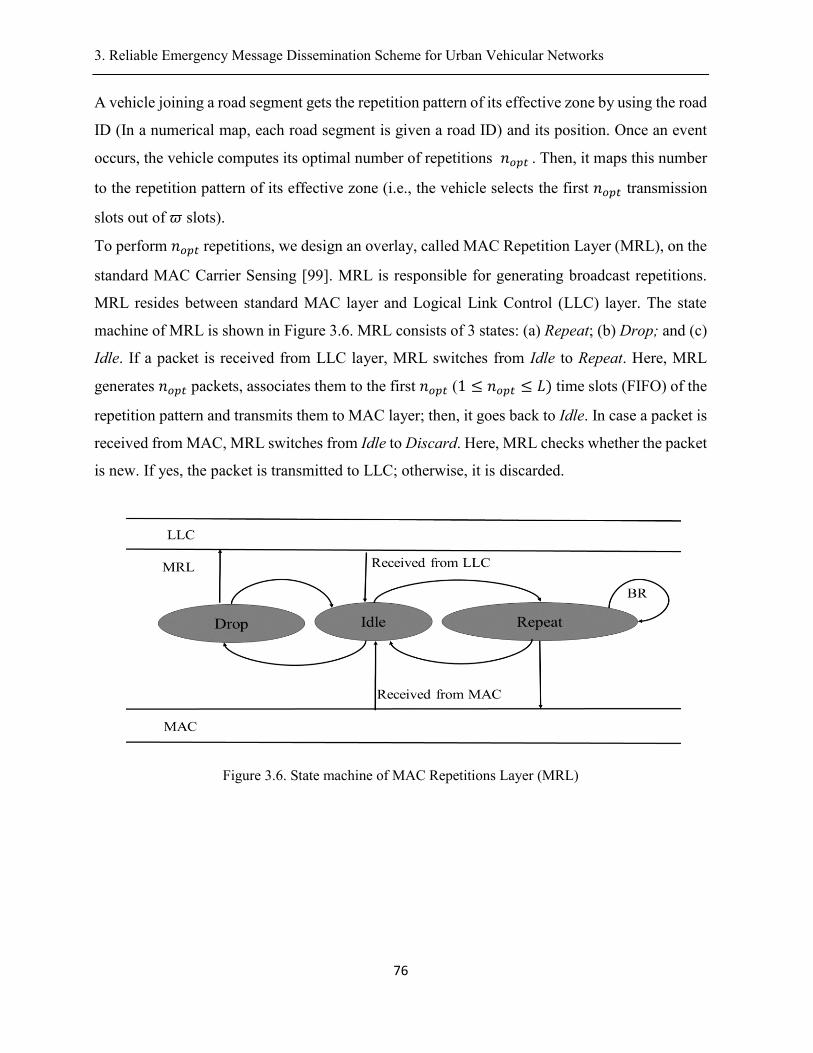
3. Reliable Emergency Message Dissemination Scheme for Urban Vehicular Networks .
76
A vehicle joining a road segment gets the repetition pattern of its effective zone by using the road
ID (In a numerical map, each road segment is given a road ID) and its position. Once an event
occurs, the vehicle computes its optimal number of repetitions 𝑛𝑜𝑝𝑡. Then, it maps this number
to the repetition pattern of its effective zone (i.e., the vehicle selects the first 𝑛𝑜𝑝𝑡 transmission
slots out of 𝜛 slots).
To perform 𝑛𝑜𝑝𝑡repetitions, we design an overlay, called MAC Repetition Layer (MRL), on the
standard MAC Carrier Sensing [99]. MRL is responsible for generating broadcast repetitions.
MRL resides between standard MAC layer and Logical Link Control (LLC) layer. The state
machine of MRL is shown in Figure 3.6. MRL consists of 3 states: (a) Repeat; (b) Drop; and (c)
Idle. If a packet is received from LLC layer, MRL switches from Idle to Repeat. Here, MRL
generates 𝑛𝑜𝑝𝑡 packets, associates them to the first 𝑛𝑜𝑝𝑡 (1 ≤ 𝑛𝑜𝑝𝑡 ≤ 𝐿) time slots (FIFO) of the
repetition pattern and transmits them to MAC layer; then, it goes back to Idle. In case a packet is
received from MAC, MRL switches from Idle to Discard. Here, MRL checks whether the packet
is new. If yes, the packet is transmitted to LLC; otherwise, it is discarded.
Figure 3.6. State machine of MAC Repetitions Layer (MRL)
3. Reliable Emergency Message Dissemination Scheme for Urban Vehicular Networks .
77
3.8. Forwarders selection
To relay the message to next hop, REMD executes FS. The main idea of FS is to select
multiple next-hop forwarders having best link reception quality 𝑄(𝑥, 𝑡)). Let 𝑛𝐹 be the number
of forwarders. Multiple forwarders allow avoiding single forwarder limitations; if only one
vehicle is chosen as a forwarder and if that vehicle malfunctions or moves away (i.e., leaves the
road segment) the message dissemination will be stopped. For simplification, we take number of
repetitions 𝑛𝑜𝑝𝑡 as a reasonable value for 𝑛𝐹. To ensure successful message reception, forwarders
should have high reception probability. Furthermore, it is a known fact that forwarders locations
should be close to the border in order to reduce multi-hop latency. FS consists of two steps:
Reception-based selection:
The sender makes use of link reception quality information to select forwarders. Forwarders
having good link reception quality are better choice to successfully receive the message and
retransmit it. Consider neighbors’ information is available (i.e., using exchanged beacons). Let
𝑣𝑁𝑔 denotes the set of cells in transmission range having vehicles. For each 𝑥 ∈ 𝑣𝑁𝑔 , the sender
extracts the corresponding link reception quality 𝑄(𝑥, 𝑡), 1 ≤ 𝑥 ≤ 𝑁𝑔 from the most recent CP
packet and picks the best 𝑛𝐹 elements of 𝑣𝑁𝑔 (in terms of link reception quality); then, it creates
a set 𝑣𝑞 that includes these elements ordered from best to worst (in terms of link reception
quality).
Position-based selection:
In order to reduce hop count, the sender ensures that the forwarders locations are close to the
border. To achieve this, for each location 𝑥 ∈ 𝑣𝑞 , the sender makes use of a location-shifting
technique 𝜏(𝑥) that moves 𝑥to the closest location y to the border while preserving an equivalent
link reception quality. In practice, the sender sets up, for each cell, 𝑥 ∈ 𝑣𝑞, a relative 2D
coordinate system {𝑋, 𝑌} having the origin x. The X-axis corresponds to reception quality values.
The Y-axis corresponds to cells in transmission range. Let 𝐷(𝑥, 𝑦) define a distance function, on
X-axis, such that 𝐷(𝑥, 𝑦) = |𝑄(𝑥, 𝑡) − 𝑄(𝑦, 𝑡)|. Let 𝐶(𝑥, 𝑦) define a distance function, on Y-
axis, such that 𝐶(𝑥, 𝑦) = |𝑥 − 𝑦|. Let 𝑡𝐷(𝑥,𝑦)⃗⃗ ⃗⃗ ⃗⃗ ⃗⃗ ⃗⃗ ⃗⃗ ⃗⃗ define a translation operation on X-axis.
𝑥 ↦ 𝑡𝐷(𝑥,𝑦)⃗⃗ ⃗⃗ ⃗⃗ ⃗⃗ ⃗⃗ ⃗⃗ ⃗⃗ (𝑥) = {
𝑦if ‖𝐷(𝑥, 𝑦)⃗⃗ ⃗⃗ ⃗⃗ ⃗⃗ ⃗⃗ ⃗⃗ ⃗⃗ ‖ ≤ 𝐿𝑡ℎ
𝑥else(24)
3. Reliable Emergency Message Dissemination Scheme for Urban Vehicular Networks .
78
Specifically, the translation operation 𝑡𝐷(𝑥,𝑦)⃗⃗ ⃗⃗ ⃗⃗ ⃗⃗ ⃗⃗ ⃗⃗ ⃗⃗ (𝑥)assigns to cell 𝑥 ∈ 𝑣𝑞 a cell y∈ 𝑣𝑞̅̅ ̅ having an
equivalent link reception quality (‖𝐷(𝑥, 𝑦)⃗⃗ ⃗⃗ ⃗⃗ ⃗⃗ ⃗⃗ ⃗⃗ ⃗⃗ ‖ ≤ 𝐿𝑡ℎ). In practice, the value of 𝐿𝑡ℎ is set to
0.01because we are not able to achieve 100% equivalency. Let 𝑡𝑥𝑦⃗⃗⃗⃗ ⃗ define a translation operation
on Y-axis:
𝑡𝑥,𝑦⃗⃗⃗⃗ ⃗⃗ :𝑣𝑞 ⟶ 𝑣𝑞̅̅ ̅(25)
𝑡𝑥𝑦⃗⃗⃗⃗ ⃗ = {𝑦𝑖𝑓𝑦 ≥ 𝑥 ∧ max
𝑦(𝐶(𝑥, 𝑦))
𝑥else
Specifically, the translation operation 𝑡𝑥𝑦⃗⃗⃗⃗ ⃗ assigns to cell 𝑥 ∈ 𝑣𝑞a cell y such that y is the closest
cell to the border. Finally, the distance shifting technique 𝜏(𝑥) combines Equation (24) and
Equation (25) in order to obtain the final forwarder location 𝜏(𝑥) defined as follows:
𝜏(𝑥) = 𝑡𝑥𝑦⃗⃗⃗⃗ ⃗𝜊 (𝑡𝐷(𝑥,𝑦)⃗⃗ ⃗⃗ ⃗⃗ ⃗⃗ ⃗⃗ ⃗⃗ ⃗⃗ (𝑥))=y ⇔ (max𝑦∈𝑣𝑞̅̅̅̅
(|𝑥 − 𝑦|) ∧ (‖𝐷(𝑥, 𝑦)⃗⃗ ⃗⃗ ⃗⃗ ⃗⃗ ⃗⃗ ⃗⃗ ⃗⃗ ‖ ≤ 𝐿𝑡ℎ) ∧ (𝑦 ≥ 𝑥)(26)
Let 𝑣𝐹 denote the set of resulting forwarders locations. The sender applies a prioritization rule
𝜑𝑖(1 ≤ 𝑖 ≤ 𝑛𝐹) to forwarders locations in 𝑣𝐹 . The priorities 𝜑𝑖 are specified in Equation (27).
𝜑𝑖 = 𝜑(𝑣𝐹(𝑖)) = 𝑖(27)
The locations of forwarders and their priorities 𝜑𝑖 are included in the emergency message. Such
an information is useful to coordinate among forwarders in the C-reliability phase.
3.9. C-Reliability
This phase is executed by forwarders of same hop. The forwarders cooperatively perform
optimal broadcast repetitions with the objective to reinforce achieving high broadcast reliability.
In addition, the forwarders coordinate to select next-hop forwarders. To achieve this, the
forwarders take the role of broadcasting the message iteratively with respect to their priorities
𝜑𝑖. Figure 3.7 shows the state machine of C-Reliability phase. Each forwarder 𝑗 (1 ≤ 𝑗 ≤ 𝑛𝐹) is
assigned a broadcasting timer Tac(j) and its initial value is indicated in Equation (28). If the
broadcasting timer expires, corresponding forwarder 𝑗 performs nre(𝑗) repetitions; initial number
3. Reliable Emergency Message Dissemination Scheme for Urban Vehicular Networks .
79
of repetitions is indicated in Equation (30). Otherwise, the corresponding forwarder is suspended
and the value of its broadcasting timer is updated using Equation (29). Similarly, the number of
repetitions per forwarder is updated using Equation (31). Initially, highest priority forwarder
(with max𝑖
𝜑𝑖) executes broadcast repetitions (BR) and selects next-hop forwarders while
forwarders at lower priorities are suspended. Lower priority forwarders overhear message
transmissions and record failed receptions as specified in Equation (31) as long as their
broadcasting timer is not expired. Indeed, the repetitions are either successfully transmitted or
lost before broadcasting timer of forwarder j expires. If broadcasting timer 𝑇𝑎𝑐(𝑗) of forwarder
j expires, we distinguish three cases:
(a) Case 1:
Current forwarder j failed to receive all repetitions of higher priority forwarder(s) (nre(𝑗) =
𝑛𝑜𝑝𝑡). This means that higher priority forwarders are malfunctioning or have moved away. Thus,
current forwarder j executes forwarders selection (FS) before broadcasting the repetitions.
(b) Case 2:
Current forwarder j successfully received all repetitions of higher priority forwarders
(nre(j) = 0). In this case, current forwarder j remains in idle state and suspends its broadcasting
timer.
(c) Case 3:
Current forwarder j didn’t receive successfully all repetitions of higher-priority forwarders (
𝑛𝐹 > nre(j) > 0). This situation usually occurs when higher-priority forwarders leave the
transmission range before accomplishing 𝑛𝑜𝑝𝑡repetitions. Thus, current forwarder j extracts
next-hop forwarders list from the already successfully received repetitions and carries out the
rest of repetitions as specified in Equation (31). As long as Equation (33) is not verified, the
reliability requirement in current hop is not achieved and the coordination process among
forwarders continues.
Tac(j) = TFS + nopt ∗ TData(28)
Tac(j) = (j − 1) ∗ ∆sj + n𝑟𝑒(j) ∗ TData(29)
nre(𝑗) = n𝑜𝑝𝑡(30)

3. Reliable Emergency Message Dissemination Scheme for Urban Vehicular Networks .
80
𝑛𝑟𝑒(𝑗) = 𝑛𝑜𝑝𝑡 − (∑(𝑛𝑜𝑝𝑡 − nre(i − 1))
𝑖=𝑗
𝑖=3
)(31)
Figure 3.7. State machine diagram of Cooperative reliability
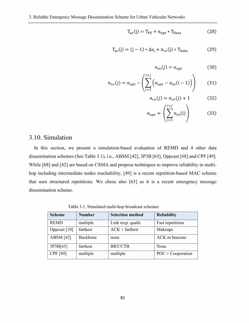
3. Reliable Emergency Message Dissemination Scheme for Urban Vehicular Networks .
81
Tac(j) = TFS + nopt ∗ TData(28)
Tac(j) = (j − 1) ∗ ∆sj + n𝑟𝑒(j) ∗ TData(29)
nre(𝑗) = n𝑜𝑝𝑡(30)
𝑛𝑟𝑒(𝑗) = 𝑛𝑜𝑝𝑡 − (∑(𝑛𝑜𝑝𝑡 − nre(i − 1))
𝑖=𝑗
𝑖=3
)(31)
𝑛𝑟𝑒(𝑗) = 𝑛𝑟𝑒(𝑗) + 1(32)
𝑛𝑜𝑝𝑡 =(∑nre(i)
𝑖=𝑗
𝑖=1
)(33)
3.10. Simulation
In this section, we present a simulation-based evaluation of REMD and 4 other data
dissemination schemes (See Table 3.1), i.e., ABSM [42], 3P3B [63], Oppcast [68] and CPF [49].
While [68] and [42] are based on CSMA and propose techniques to improve reliability in multi-
hop including intermediate nodes reachability, [49] is a recent repetition-based MAC scheme
that uses structured repetitions. We chose also [63] as it is a recent emergency message
dissemination scheme.
Table 3.1. Simulated multi-hop broadcast schemes
Scheme Number Selection method Reliability
REMD multiple Link recp. qualit. Fast repetitions
Oppcast [10] farthest ACK + farthest Makeups
ABSM [42] Backbone none ACK in beacons
3P3B[63] farthest BRT/CTB None
CPF [49] multiple multiple POC + Cooperation
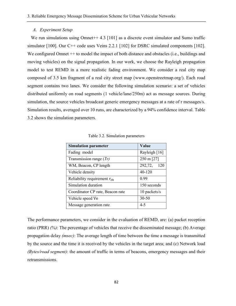
3. Reliable Emergency Message Dissemination Scheme for Urban Vehicular Networks .
82
A. Experiment Setup
We run simulations using Omnet++ 4.3 [101] as a discrete event simulator and Sumo traffic
simulator [100]. Our C++ code uses Veins 2.2.1 [102] for DSRC simulated components [102].
We configured Omnet ++ to model the impact of both distance and obstacles (i.e., buildings and
moving vehicles) on the signal propagation. In our work, we choose the Rayleigh propagation
model to test REMD in a more realistic fading environment. We consider a real city map
composed of 3.5 km fragment of a real city street map (www.openstreetmap.org/). Each road
segment contains two lanes. We consider the following simulation scenario: a set of vehicles
distributed uniformly on road segments (1 vehicle/lane/250m) act as message sources. During
simulation, the source vehicles broadcast generic emergency messages at a rate of r messages/s.
Simulation results, averaged over 10 runs, are characterized by a 94% confidence interval. Table
3.2 shows the simulation parameters.
Table 3.2. Simulation parameters
Simulation parameter Value
Fading model Rayleigh [16]
Transmission range (Tr) 250 m [27]
WM, Beacon, CP length 292,72, 120
bytes. Vehicle density 40-120
cars/km Reliability requirement 𝑟𝑡ℎ 0.99
Simulation duration 150 seconds
Coordinator CP rate, Beacon rate 10 packets/s
Vehicle speed Ve 30-50
km/hour Message generation rate 4-5
messages/s
The performance parameters, we consider in the evaluation of REMD, are: (a) packet reception
ratio (PRR) (%): The percentage of vehicles that receive the disseminated message; (b) Average
propagation delay (msec): The average length of time between the time a message is transmitted
by the source and the time it is received by the vehicles in the target area; and (c) Network load
(Bytes/road segment): the amount of traffic in terms of beacons, emergency messages and their
retransmissions.
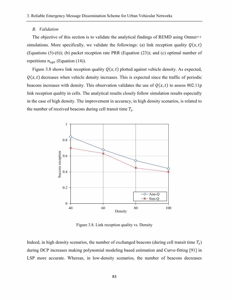
3. Reliable Emergency Message Dissemination Scheme for Urban Vehicular Networks .
83
B. Validation
The objective of this section is to validate the analytical findings of REMD using Omnet++
simulations. More specifically, we validate the followings: (a) link reception quality 𝑄(𝑥, 𝑡)
(Equations (5)-(6)); (b) packet reception rate PRR (Equation (23)); and (c) optimal number of
repetitions 𝑛𝑜𝑝𝑡 (Equation (14)).
Figure 3.8 shows link reception quality 𝑄(𝑥, 𝑡)plotted against vehicle density. As expected,
𝑄(𝑥, 𝑡)decreases when vehicle density increases. This is expected since the traffic of periodic
beacons increases with density. This observation validates the use of 𝑄(𝑥, 𝑡) to assess 802.11p
link reception quality in cells. The analytical results closely follow simulation results especially
in the case of high density. The improvement in accuracy, in high density scenarios, is related to
the number of received beacons during cell transit time 𝑇𝑠.
Figure 3.8. Link reception quality vs. Density
Indeed, in high density scenarios, the number of exchanged beacons (during cell transit time 𝑇𝑠)
during DCP increases making polynomial modeling based estimation and Curve-fitting [91] in
LSP more accurate. Whereas, in low-density scenarios, the number of beacons decreases
0
0.2
0.4
0.6
0.8
1
40 60 80 100
Succ
ess
rece
pti
on
Density
Ana-Q
Sim-Q
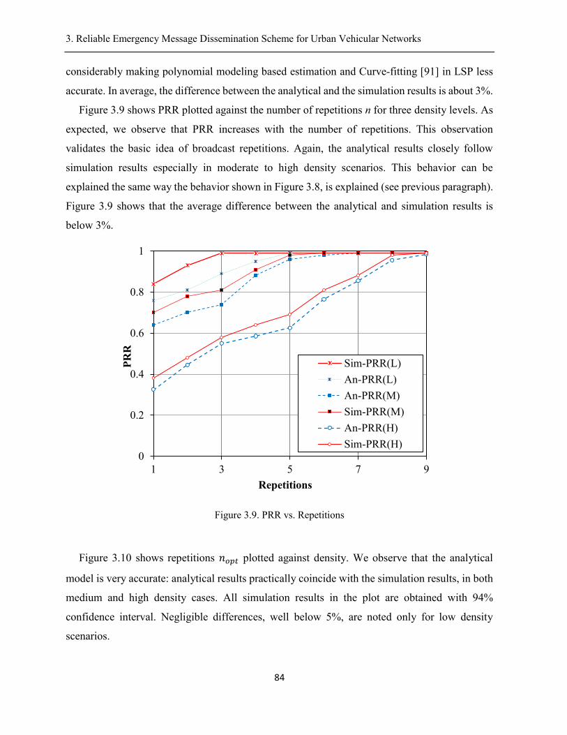
3. Reliable Emergency Message Dissemination Scheme for Urban Vehicular Networks .
84
considerably making polynomial modeling based estimation and Curve-fitting [91] in LSP less
accurate. In average, the difference between the analytical and the simulation results is about 3%.
Figure 3.9 shows PRR plotted against the number of repetitions n for three density levels. As
expected, we observe that PRR increases with the number of repetitions. This observation
validates the basic idea of broadcast repetitions. Again, the analytical results closely follow
simulation results especially in moderate to high density scenarios. This behavior can be
explained the same way the behavior shown in Figure 3.8, is explained (see previous paragraph).
Figure 3.9 shows that the average difference between the analytical and simulation results is
below 3%.
Figure 3.9. PRR vs. Repetitions
Figure 3.10 shows repetitions 𝑛𝑜𝑝𝑡 plotted against density. We observe that the analytical
model is very accurate: analytical results practically coincide with the simulation results, in both
medium and high density cases. All simulation results in the plot are obtained with 94%
confidence interval. Negligible differences, well below 5%, are noted only for low density
scenarios.
0
0.2
0.4
0.6
0.8
1
1 3 5 7 9
PR
R
Repetitions
Sim-PRR(L)
An-PRR(L)
An-PRR(M)
Sim-PRR(M)
An-PRR(H)
Sim-PRR(H)
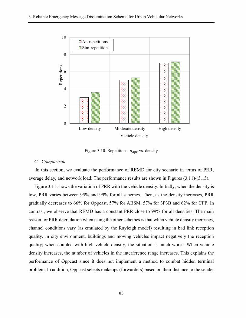
3. Reliable Emergency Message Dissemination Scheme for Urban Vehicular Networks .
85
Figure 3.10. Repetitions 𝑛𝑜𝑝𝑡 vs. density
C. Comparison
In this section, we evaluate the performance of REMD for city scenario in terms of PRR,
average delay, and network load. The performance results are shown in Figures (3.11)-(3.13).
Figure 3.11 shows the variation of PRR with the vehicle density. Initially, when the density is
low, PRR varies between 95% and 99% for all schemes. Then, as the density increases, PRR
gradually decreases to 66% for Oppcast, 57% for ABSM, 57% for 3P3B and 62% for CFP. In
contrast, we observe that REMD has a constant PRR close to 99% for all densities. The main
reason for PRR degradation when using the other schemes is that when vehicle density increases,
channel conditions vary (as emulated by the Rayleigh model) resulting in bad link reception
quality. In city environment, buildings and moving vehicles impact negatively the reception
quality; when coupled with high vehicle density, the situation is much worse. When vehicle
density increases, the number of vehicles in the interference range increases. This explains the
performance of Oppcast since it does not implement a method to combat hidden terminal
problem. In addition, Oppcast selects makeups (forwarders) based on their distance to the sender
0
2
4
6
8
10
Low density Moderate density High density
Rep
etit
ion
s
Vehicle density
An-repetitions
Sim-repetition
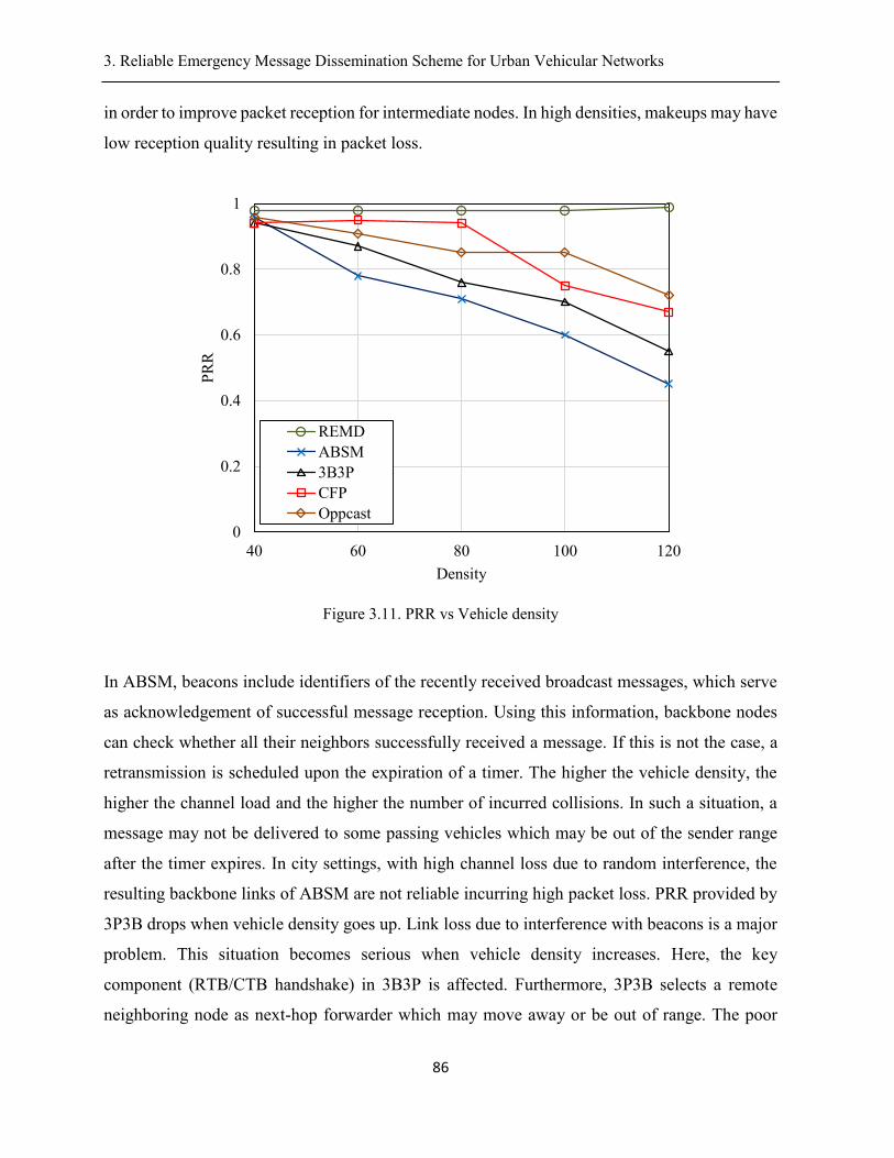
3. Reliable Emergency Message Dissemination Scheme for Urban Vehicular Networks .
86
in order to improve packet reception for intermediate nodes. In high densities, makeups may have
low reception quality resulting in packet loss.
Figure 3.11. PRR vs Vehicle density
In ABSM, beacons include identifiers of the recently received broadcast messages, which serve
as acknowledgement of successful message reception. Using this information, backbone nodes
can check whether all their neighbors successfully received a message. If this is not the case, a
retransmission is scheduled upon the expiration of a timer. The higher the vehicle density, the
higher the channel load and the higher the number of incurred collisions. In such a situation, a
message may not be delivered to some passing vehicles which may be out of the sender range
after the timer expires. In city settings, with high channel loss due to random interference, the
resulting backbone links of ABSM are not reliable incurring high packet loss. PRR provided by
3P3B drops when vehicle density goes up. Link loss due to interference with beacons is a major
problem. This situation becomes serious when vehicle density increases. Here, the key
component (RTB/CTB handshake) in 3B3P is affected. Furthermore, 3P3B selects a remote
neighboring node as next-hop forwarder which may move away or be out of range. The poor
0
0.2
0.4
0.6
0.8
1
40 60 80 100 120
PR
R
Density
REMD
ABSM
3B3P
CFP
Oppcast
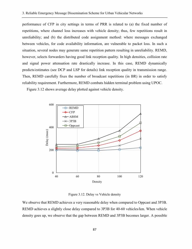
3. Reliable Emergency Message Dissemination Scheme for Urban Vehicular Networks .
87
performance of CFP in city settings in terms of PRR is related to (a) the fixed number of
repetitions, where channel loss increases with vehicle density; thus, few repetitions result in
unreliability; and (b) the distributed code assignment method: where messages exchanged
between vehicles, for code availability information, are vulnerable to packet loss. In such a
situation, several nodes may generate same repetition pattern resulting in unreliability. REMD,
however, selects forwarders having good link reception quality. In high densities, collision rate
and signal power attenuation rate drastically increase. In this case, REMD dynamically
predicts/estimates (see DCP and LSP for details) link reception quality in transmission range.
Then, REMD carefully fixes the number of broadcast repetitions (in BR) in order to satisfy
reliability requirement. Furthermore, REMD combats hidden terminal problem using UPOC.
Figure 3.12 shows average delay plotted against vehicle density.
Figure 3.12. Delay vs Vehicle density
We observe that REMD achieves a very reasonable delay when compared to Oppcast and 3P3B.
REMD achieves a slightly close delay compared to 3P3B for 40-60 vehicles/km. When vehicle
density goes up, we observe that the gap between REMD and 3P3B becomes larger. A possible
0
200
400
600
40 60 80 100 120
Del
ay (
mse
c)
Density
REMD
CFP
ABSM
3P3B
Oppcast
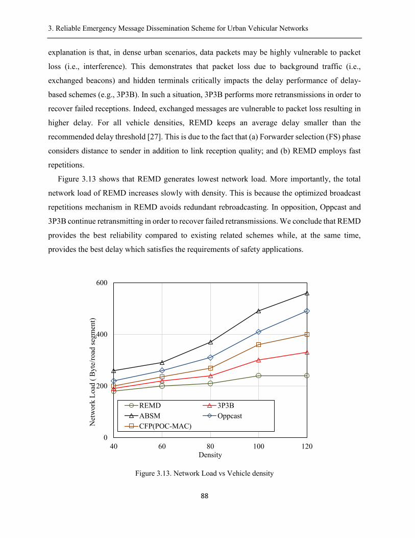
3. Reliable Emergency Message Dissemination Scheme for Urban Vehicular Networks .
88
explanation is that, in dense urban scenarios, data packets may be highly vulnerable to packet
loss (i.e., interference). This demonstrates that packet loss due to background traffic (i.e.,
exchanged beacons) and hidden terminals critically impacts the delay performance of delay-
based schemes (e.g., 3P3B). In such a situation, 3P3B performs more retransmissions in order to
recover failed receptions. Indeed, exchanged messages are vulnerable to packet loss resulting in
higher delay. For all vehicle densities, REMD keeps an average delay smaller than the
recommended delay threshold [27]. This is due to the fact that (a) Forwarder selection (FS) phase
considers distance to sender in addition to link reception quality; and (b) REMD employs fast
repetitions.
Figure 3.13 shows that REMD generates lowest network load. More importantly, the total
network load of REMD increases slowly with density. This is because the optimized broadcast
repetitions mechanism in REMD avoids redundant rebroadcasting. In opposition, Oppcast and
3P3B continue retransmitting in order to recover failed retransmissions. We conclude that REMD
provides the best reliability compared to existing related schemes while, at the same time,
provides the best delay which satisfies the requirements of safety applications.
Figure 3.13. Network Load vs Vehicle density
0
200
400
600
40 60 80 100 120
Net
wo
rk L
oad
( B
yte
/road
seg
men
t)
Density
REMD 3P3B
ABSM Oppcast
CFP(POC-MAC)
3. Reliable Emergency Message Dissemination Scheme for Urban Vehicular Networks .
89
3.11. Conclusion
We proposed REMD as a multi-hop reliable dissemination scheme for urban vehicular
networks, compatible with IEEE 802.11p. REMD aims to ensure high broadcast reliability while
preserving low end-to-end delay for safety applications. The proposed cell concept provides fine-
grained information about wireless channel conditions. By employing curve fitting and
polynomial modeling, we are able to predict/estimate an accurate link reception quality in cells.
A Max-Min optimisation problem is proposed to compute an optimal number of repetitions while
ensuring predefined reliability requirements at each hop. A stochastic modeling approach is used
to solve the Max-Min optimization problem. The number of successful receivers is computed
from a Poisson Binomial distribution (PBD). FFT enables an exact solution to PBD in 𝑂(𝑛 ×
𝑙𝑜𝑔(𝑛). To combat hidden terminal problem, Uni-Polar orthogonal codes are applied to the city
street network. This paper also proposes a solution for efficient next-hop forwarders selection.
REMD selects multiple forwarders with good link reception quality together with their locations
at each hop. The forwarders use cooperative transmissions with the objective to achieve high
reliability in intermediate hops. Using simulations, we validated the analytical model of REMD.
We evaluated, via simulations, the performance of REMD and did show its outperformance
compared to existing related schemes. Future work will investigate the use of machine learning
tools to improve the estimation accuracy of link reception qualities in different cells of a given
zone.
4. Bayesian Networks based Reliable Broadcast in Vehicular Networks
90
Chapter 4
Bayesian Networks based Reliable Broadcast in
Vehicular Networks
Abstract
Reliability is a key requirement of multi-hop safety message broadcasting. DSRC/802.11p
MAC layer has strict reliability requirement for ITS safety applications. In city environment,
transmission in wireless medium is vulnerable to packet collisions and interferences. Cross
channel interference is quite predominant in the presence of high rise buildings and concurrent
transmissions. Achieving very high reliability (e.g., 0.99) in the presence of all kinds of wireless
network vulnerabilities is a major challenge in urban vehicular networks. This paper proposes a
new broadcast scheme, called Bayesian networks and unipolar orthogonal Code based Reliable
multi-hop Broadcast (BCRB) to address this issue. Our objective is to guarantee strict reliability
requirement (e.g., 99%) in each hop using broadcast repetitions. We propose an approach, based
on using Bayesian networks, that exploits periodic exchanged beacons to accurately infer
802.11p link reception quality at each hop. Using this information, a sender determines an
optimal number of broadcast repetitions, multiple forwarders and their positions. To combat
interference, during broadcast repetitions, we make use of Uni-Polar Orthogonal Codes (UPOC).
For multi-hop transmissions, multiple forwarders cooperatively communicate at each hop with
the objective to achieve high broadcast reliability in next hop. Simulation results show that BCRB
achieves very high reliability in lossy wireless channel. Furthermore, BCRB satisfies
transmission latency requirements for time-sensitive vehicular applications with relatively low
overhead.
Key words: Broadcast Reliability, Bayesian Network, Uni-Polar Orthogonal Codes, Urban
vehicular network, stochastic modeling.
Status: This article is submitted to IEEE Transactions on Vehicular Technology 2017;
Wiem Benrhaiem and Abdelhakim Hafid
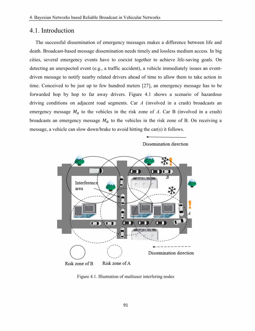
4. Bayesian Networks based Reliable Broadcast in Vehicular Networks
91
4.1. Introduction
The successful dissemination of emergency messages makes a difference between life and
death. Broadcast-based message dissemination needs timely and lossless medium access. In big
cities, several emergency events have to coexist together to achieve life-saving goals. On
detecting an unexpected event (e.g., a traffic accident), a vehicle immediately issues an event-
driven message to notify nearby related drivers ahead of time to allow them to take action in
time. Conceived to be just up to few hundred meters [27], an emergency message has to be
forwarded hop by hop to far away drivers. Figure 4.1 shows a scenario of hazardous
driving conditions on adjacent road segments. Car A (involved in a crash) broadcasts an
emergency message 𝑀𝐴 to the vehicles in the risk zone of A. Car B (involved in a crash)
broadcasts an emergency message 𝑀𝐵 to the vehicles in the risk zone of B. On receiving a
message, a vehicle can slow down/brake to avoid hitting the car(s) it follows.
Figure 4.1. Illustration of multiuser interfering nodes
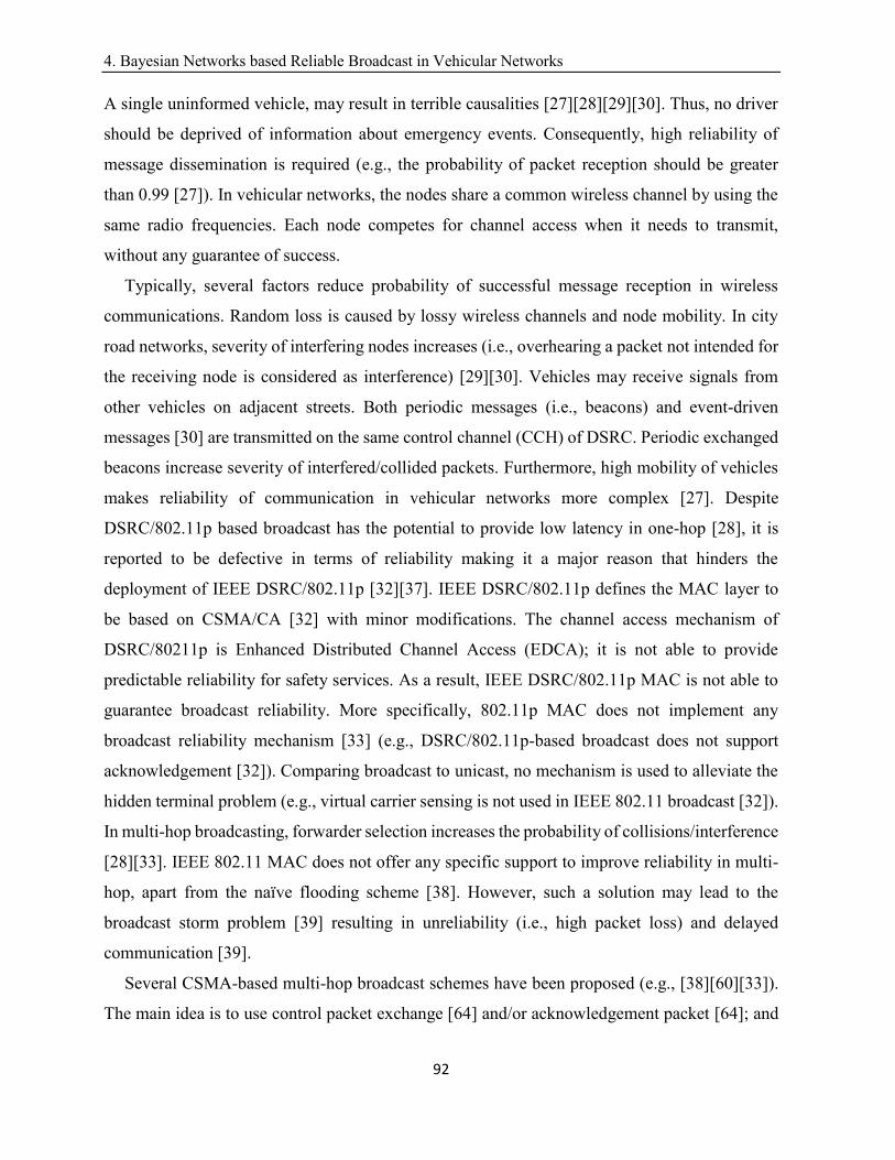
4. Bayesian Networks based Reliable Broadcast in Vehicular Networks
92
A single uninformed vehicle, may result in terrible causalities [27][28][29][30]. Thus, no driver
should be deprived of information about emergency events. Consequently, high reliability of
message dissemination is required (e.g., the probability of packet reception should be greater
than 0.99 [27]). In vehicular networks, the nodes share a common wireless channel by using the
same radio frequencies. Each node competes for channel access when it needs to transmit,
without any guarantee of success.
Typically, several factors reduce probability of successful message reception in wireless
communications. Random loss is caused by lossy wireless channels and node mobility. In city
road networks, severity of interfering nodes increases (i.e., overhearing a packet not intended for
the receiving node is considered as interference) [29][30]. Vehicles may receive signals from
other vehicles on adjacent streets. Both periodic messages (i.e., beacons) and event-driven
messages [30] are transmitted on the same control channel (CCH) of DSRC. Periodic exchanged
beacons increase severity of interfered/collided packets. Furthermore, high mobility of vehicles
makes reliability of communication in vehicular networks more complex [27]. Despite
DSRC/802.11p based broadcast has the potential to provide low latency in one-hop [28], it is
reported to be defective in terms of reliability making it a major reason that hinders the
deployment of IEEE DSRC/802.11p [32][37]. IEEE DSRC/802.11p defines the MAC layer to
be based on CSMA/CA [32] with minor modifications. The channel access mechanism of
DSRC/80211p is Enhanced Distributed Channel Access (EDCA); it is not able to provide
predictable reliability for safety services. As a result, IEEE DSRC/802.11p MAC is not able to
guarantee broadcast reliability. More specifically, 802.11p MAC does not implement any
broadcast reliability mechanism [33] (e.g., DSRC/802.11p-based broadcast does not support
acknowledgement [32]). Comparing broadcast to unicast, no mechanism is used to alleviate the
hidden terminal problem (e.g., virtual carrier sensing is not used in IEEE 802.11 broadcast [32]).
In multi-hop broadcasting, forwarder selection increases the probability of collisions/interference
[28][33]. IEEE 802.11 MAC does not offer any specific support to improve reliability in multi-
hop, apart from the naïve flooding scheme [38]. However, such a solution may lead to the
broadcast storm problem [39] resulting in unreliability (i.e., high packet loss) and delayed
communication [39].
Several CSMA-based multi-hop broadcast schemes have been proposed (e.g., [38][60][33]).
The main idea is to use control packet exchange [64] and/or acknowledgement packet [64]; and
4. Bayesian Networks based Reliable Broadcast in Vehicular Networks
93
to select a single forwarding node at each hop. DSRC/802.11p-MAC [32] can’t
characterize/detect random access events resulting in unreliability. In harsh network conditions,
a sender does not know whether its transmitted message is successfully received or not.
Furthermore, in case the forwarder has moved away or is malfunctioning, the multi-hop
communication would not be possible.
Recently, repetition-based broadcast MAC schemes [46] [48] have been proposed to enhance
broadcast reliability for safety applications. The basic idea is to repeat (i.e., transmit) the message
multiple times within a frame in order to increase reception probability; a frame consists of L
time slots. Random repetitions schemes like SFR [46] and AFR [46] randomly select repetition
slots. It has been proved that selecting k slots out of L raises the probability of successful message
reception [46]. Expanding upon this finding, structured repetitions are proposed to further protect
repeated packets from hidden terminal problem [49]. Positive Orthogonal Codes (POC), known
as Uni-Polar orthogonal codes (UPOC) [47], as structured repetition patterns, have been reported
to suppress hidden terminal problem [49]; an UPOC is a binary code of fixed length L , where
cross-correlation between any pair of code-words is less than a given value [49]. However,
without evaluating the channel condition, if fixed number of messages is forwarded within frame,
we may be sending either too few or too many packets. Too many packets may lead to
considerable overhead and too few packets may lead to unreliability. It is important to note that
most existing repetition-based MAC schemes [72][73] are not compatible with emerging
DSRC/802.11p [32].
In this paper, we propose a novel reliable multi-hop broadcast-based MAC scheme, called
BCRB, compatible with emerging IEEE DSRC/802.11p. The key contributions of this paper can
be summarized as follows:
(1) Propose a Bayesian networks based scheme to estimate, with good accuracy, link reception
quality, at different locations in the zone covered by the transmission range of the sender;
this estimation is based on beacons periodically generated by vehicles.
(2) Propose a Max-Min optimization problem, together with its resolution, that allows to
determine an optimal number of repetitions (i.e., message transmission) to satisfy 1-hop
reliability requirements. The input to this optimization problem is link reception qualities
computed in (1).
4. Bayesian Networks based Reliable Broadcast in Vehicular Networks
94
(3) Propose an UPOC-based scheme that carefully generates repetition patterns to
minimize/avoid interferences between senders (vehicles) located on different road segments.
(4) Propose a scheme that selects appropriate forwarders, at each hop, with the objective to
satisfy multi-hop reliability requirements; these forwarders, at each hop, cooperatively repeat
the message (based on the number of repetitions computed in (2) and repetition patterns
determined in (3)) to support reliability requirements in next hop. They cooperatively repeat
the message an optimal number of times with the goal to ensure high reliability in next hop.
The remainder of this paper is organized as follows. Section 4.2 presents related work. Section
4.3 briefly overviews BCRB. Sections 4.4-4.9 presents the components of BCRB. Section 4.10
evaluates, via simulations, the performance of BCRB. Finally, section 4.11 concludes the paper.
4.2. Related work and Motivation
In this section, we briefly review existing CSMA-based broadcast medium access control
(MAC) schemes. Then, we present repetition-based broadcast medium access control (MAC)
schemes.
A. CSMA-based broadcast
Several multi-hop broadcasting schemes have been proposed. They can be classified into 3
broad categories: Probabilistic schemes (e.g., [37], [58]), Backbone-based schemes (e.g.,
[59][44]) and Delay-based schemes (e.g., [60][33][34][61][62][63][64])
Probabilistic schemes are designed to alleviate broadcast storm problem. The main idea is to
reduce the percentage of redundant messages by selecting only some vehicles to rebroadcast
messages. SAPF [37] determines broadcast probability based on vehicles speed. Weighted p-
persistence [58], slotted 1-persistence [58], and slotted p-persistence [58] are the first proposed
broadcasting schemes. However, such schemes for multi-hop broadcasting don’t consider wireless
signal propagation issues (i.e., severe multi-path fading and shadowing). In high lossy channels,
such schemes generate redundant retransmissions and incur a large communication delay. This
makes them not suitable for safe driving in dense urban areas. Furthermore, these contributions
don’t consider MAC layer issues, such as interference management and random access. Thus,
broadcast over lossy wireless links remains unreliable.
Backbone-based schemes are designed to disseminate messages based on already formed
virtual backbone structures [65]. DBA-MAC [44] selects backbone nodes based on estimated
4. Bayesian Networks based Reliable Broadcast in Vehicular Networks
95
lifetime of wireless links. In city setting, links of the backbone nodes are vulnerable to failure
resulting in high communication overhead (creation and maintenance of backbone structure).
Surrounding buildings and mobility of nodes impact quality of wireless links resulting in week
connectivity between backbone nodes. Intermediate nodes are the vehicles located in the area
between two successive backbone nodes. ABSM [59] includes message identifier in beacons to
serve as acknowledgements. If an acknowledgement is not received from an intermediate node,
the backbone node rebroadcasts the message. The presence of obstacles may cause massive
beacon losses. In this context, ABSM [59] performs redundant retransmissions.
Delay-based schemes are designed to select the farthest neighboring node as the next relaying
node in order to reduce hop count. UMB [60] and BPAB [33] divide the transmission range into
several sectors. The vehicle that is located in the farthest sector is elected to forward the message.
UMBP [64] makes use of black-burst and asynchronous contention among remote neighboring
nodes to select a farthest node. 3P3B [63] allows the farthest possible vehicle in the farthest sector
from the sender node to perform forwarding. In PAB [34], each node receiving a packet
determines the distance with respect to the sender. Then, it picks a waiting time inversely
proportional to the distance from the sender to the receiver. The farthest node is whose timer
expires first. PMBP [61] and ROFF [62] select the farthest forwarding node according to its
distance to the sender. It is a known fact that the sender is aware of the topology change through
received beacons. The time gap between beacon sending time of a neighboring node and the time
at which that node becomes a forwarder may be very long. In such a situation, the farthest node
may not be within the range of the sender resulting in unreliability. Besides, one-hop broadcast
reception rate is lower in farthest positions due to channel fading. As a result, the farthest node
may not receive the message and the sender will remain unaware of failed reception. To overcome
such limitations, several contributions (e.g., [60][62][63]) propose to use a handshake mechanism
with the goal to decrease the impact of hidden terminal problem and/or to transmit
acknowledgements (ACKs). To combat hidden terminal problem, schemes in [60][67] use
request-to-send/clear-to-send (RTS/CTS) mechanism before transmitting a data packet. UMB
[60] uses RTS/CTS handshake with only one of the recipients among sender’s neighbors. CLBP
[67] exchanges BRTS/BCTS packets (Broadcast RTS/CTS inspired by the RTS/CTS mechanism
in IEEE802.11) before sending data packet. BPAP [33] relies on a control message exchange
similar to RTS/CTS handshake to overcome the hidden terminal problem. 3P3B [63] adopts
4. Bayesian Networks based Reliable Broadcast in Vehicular Networks
96
RTB/CTB handshake to cope with the hidden terminal problem in multi-hop wireless networks.
In city settings, control packets may be potentially lost because the length of safety messages is
short and comparable to that of RTS control packets [64]. Therefore, the probability of collision
for RTS packets is not negligible. Even if RTS/CTS handshake protects transmission of
emergency messages when multiple interfering nodes coexist, it can’t protect from shadow and
fading effects due to obstacles. Oppcast [68] and EMDOR [69] use explicit
broadcast acknowledgements (ACKs) to select forwarders. However, acknowledgement-based
mechanisms are generally not robust under harsh channel conditions. More specifically, ACK
messages are prone to interference. In city settings, the above schemes perform multiple
retransmissions that may lead to the violation of delay requirements for safety applications.
With respect to the reachability of intermediate nodes, few schemes propose methods to ensure
successful packet reception for intermediate nodes:
(a) Schemes in [60][63][67] perform message “overhearing”; if the farthest node is successfully
selected, then the other nodes in between (i.e., intermediate nodes) can overhear the source
transmissions [70]. In lossy channel, transmissions are vulnerable to interference/collisions.
Here, an intermediate node may not receive the message;
(b) Scheme in [69] performs ACK-overhearing. After transmitting the message, the forwarder
sends an ACK to the sender. If an intermediate node overhears an ACK but it didn’t receive the
corresponding message, it requests the sender to perform rebroadcasting. In the case of multiple
nodes not receiving the message, the sender has to do multiple retransmissions that may lead to
low packet reception rate (e.g., because of collisions). Hence, ‘’Overhearing’’ does not guarantee
successful message reception; and
(c) Scheme in [68] elects intermediate forwarders “makeups” at each hop to enhance one-hop
reliability. The makeups perform rebroadcasting to enhance packet reception rate (PRR).
However, the ‘makeups’ are selected, based on their distance to the sender. In adverse network
settings, selected makeups may have low link reception quality resulting in a non-guaranteed
reliability for intermediate nodes.
To conclude, conventional DSRC/802.11p-based MAC broadcast schemes are defective in
terms of reliability.
4. Bayesian Networks based Reliable Broadcast in Vehicular Networks
97
B. Repetition-based MAC schemes
The objective of message repetition [46] is to meet one-hop requirements in terms of reliability
and latency [46]. The basic idea is to divide time into frames of fixed size. A frame of L slots
(equal to the message lifetime) is allocated to each vehicle intending to transmit an
emergency message. Slot length equals to the transmission time of a single packet [105]. A
vehicle is allowed to repeat the message multiple times within a frame. The intuition is repeating
the message more than once raises probability of reception. Message repetition schemes can be
divided into two broad categories:
(a) Random repetitions [46][48], where the repetition pattern (timeslots in which a node is
allowed to transmit in a frame) is chosen randomly. SPR [46] transmits the message in each
timeslot with probability p and remains idle with probability 1 − p. In this approach a packet
may be transmitted L times or not transmitted at all. SFR [46] randomly chooses k slots out of
the L slots. It is proved in [46] that SFR is better than SPR and IEEE 802.11a in terms of
reliability. FR-EMD [71] extends SFR to multi-hop and adjusts the number of repetitions
according to vehicle density. However, it does not take into account signal propagation issues
(e.g., slow-fading and shadowing) caused by obstacles. RB-CD [48] focuses on reliable
broadcasting for emergency messages. The computation of the number of repetitions does not
consider channel conditions. Furthermore, RB-CD [48] does not combat hidden terminal
problem. In situations where a large number of transmissions happen, random access results in
high packet loss rate. This is because randomly choosing transmission slots incurs
collisions/interference; and
(b) Structured repetitions [72][73][49], where the transmission slots are obtained based on
unipolar orthogonal codes. It is shown in [72] that transmission/repetition patterns obtained from
Optical Orthogonal codes [47] perform better than SPR [46] and SFR [46] in terms of probability
of transmission success and delay. Unipolar orthogonal codes [47] represent binary sequences
{0,1} with small cross-correlation. Obtaining repetition patterns from these codes guarantees that
maximum number of times that two vehicles simultaneously transmit is less than the cross-
correlation. Schemes in [72][73] focus on broadcast reliability of periodic beacon messages using
Unipolar Orthogonal Codes. The scheme in [72] does not account for fast moving vehicles and
highly dynamic wireless channel. In POC-MAC [73], repetition patterns distribution uses
considerable channel resources (i.e., available codes are acquired through message-passing) in
4. Bayesian Networks based Reliable Broadcast in Vehicular Networks
98
high density network. In lossy channel, the exchanged messages (message-passing between
vehicles to update codes availability information) can be lost. This results in erroneous code
assignment (i.e., two neighboring nodes may allocate same code) resulting in unreliability.
Furthermore, the authors compute the probability of transmission success without taking into
account signal propagation issues. In addition, repetition-based MAC schemes [72][73] are not
compatible with emerging DSRC/802.11p [32]. CPF [49] extends POC-MAC [73] for multi-hop
emergency message dissemination in highway scenarios. In lossy wireless channel, selected
forwarders may have bad link reception quality resulting in failed receptions; whatever the
number of repetitions, if a forwarder position is exposed to shadowing and multipath effects, the
message dissemination may fail resulting in unreliability. CPF does not guarantee high broadcast
reliability in lossy channel. Indeed, if fixed number of message repetitions is forwarded over a
frame, they may be sending either too few or too many packets. Too many packets lead to
message overhead resulting in collisions and too few packets lead to unreliability. Hence, an
optimal number of repetitions must be determined according to channel conditions. In a previous
work, we proposed REMD [106] which uses structured repetitions to ensure high broadcast
reliability. It computes an optimal number of repetitions based on an estimation of link reception
quality in different locations (called also cells) in the transmission range of the sender. REMD
proposes an analytical model to estimate link reception quality. However, it makes the
assumption that link reception qualities of adjacent cells are independent which is not realistic in
real-life scenarios.
In this paper, we propose BCRB that uses a machine learning-based approach to estimate link
reception quality at different locations in the zone covered by the transmission range of the
sender; BCRB does not make any assumption about the link reception qualities of adjacent nodes.
The goal of this paper is to develop an efficient scheme, compatible with DSRC/80211p-based
MAC that makes use of UPOC and message repetition, while taking into account real-time
channel conditions, for reliable multi-hop communication in urban scenarios. In the following
sections, we will present the details of this scheme.
4.3. BCRB: An Overview
The objective of BCRB is to disseminate emergency messages with very high reliability (e.g.,
𝑟𝑡ℎ=99%)) [107] in vehicular networks. The basic idea, behind BCRB, is to transmit/repeat the
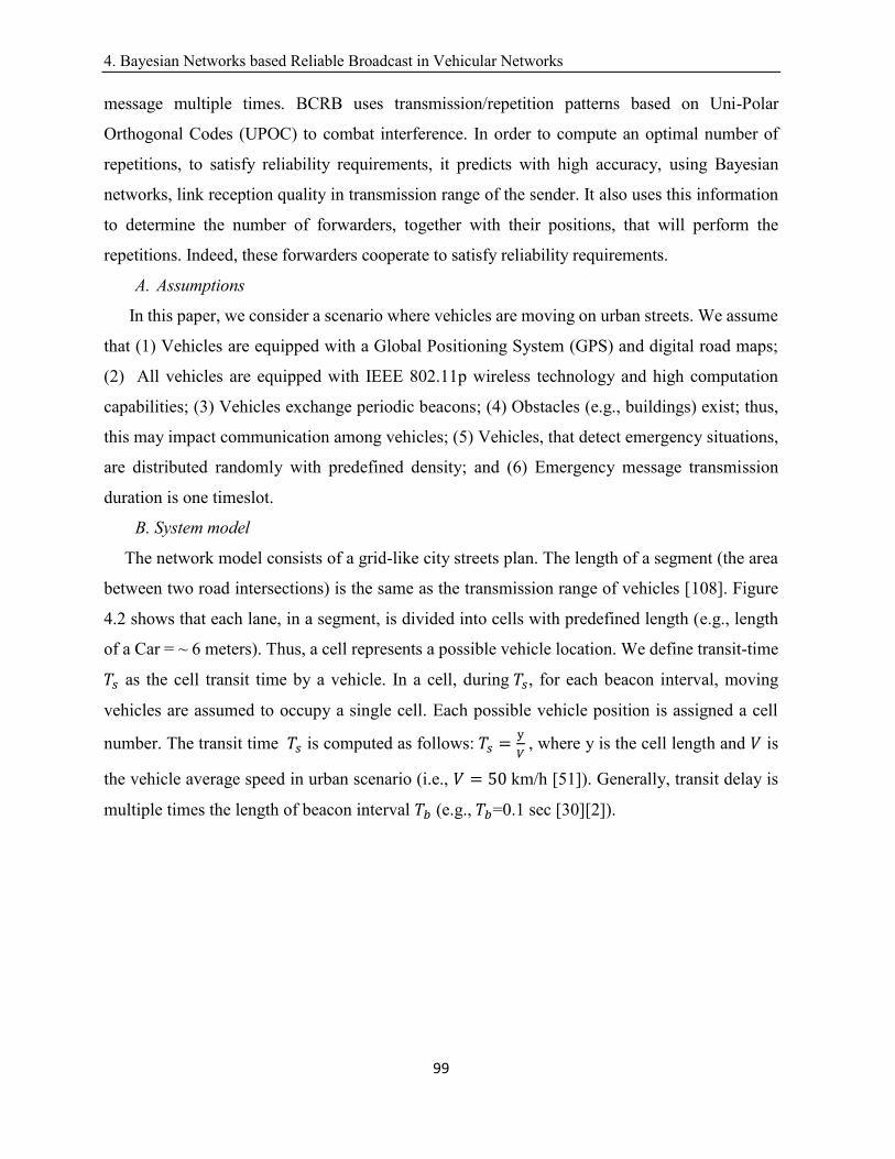
4. Bayesian Networks based Reliable Broadcast in Vehicular Networks
99
message multiple times. BCRB uses transmission/repetition patterns based on Uni-Polar
Orthogonal Codes (UPOC) to combat interference. In order to compute an optimal number of
repetitions, to satisfy reliability requirements, it predicts with high accuracy, using Bayesian
networks, link reception quality in transmission range of the sender. It also uses this information
to determine the number of forwarders, together with their positions, that will perform the
repetitions. Indeed, these forwarders cooperate to satisfy reliability requirements.
A. Assumptions
In this paper, we consider a scenario where vehicles are moving on urban streets. We assume
that (1) Vehicles are equipped with a Global Positioning System (GPS) and digital road maps;
(2) All vehicles are equipped with IEEE 802.11p wireless technology and high computation
capabilities; (3) Vehicles exchange periodic beacons; (4) Obstacles (e.g., buildings) exist; thus,
this may impact communication among vehicles; (5) Vehicles, that detect emergency situations,
are distributed randomly with predefined density; and (6) Emergency message transmission
duration is one timeslot.
B. System model
The network model consists of a grid-like city streets plan. The length of a segment (the area
between two road intersections) is the same as the transmission range of vehicles [108]. Figure
4.2 shows that each lane, in a segment, is divided into cells with predefined length (e.g., length
of a Car = ~ 6 meters). Thus, a cell represents a possible vehicle location. We define transit-time
𝑇𝑠 as the cell transit time by a vehicle. In a cell, during𝑇𝑠, for each beacon interval, moving
vehicles are assumed to occupy a single cell. Each possible vehicle position is assigned a cell
number. The transit time 𝑇𝑠 is computed as follows:𝑇𝑠 =y
𝑉, where y is the cell length and 𝑉 is
the vehicle average speed in urban scenario (i.e., 𝑉 = 50km/h [51]). Generally, transit delay is
multiple times the length of beacon interval 𝑇𝑏 (e.g.,𝑇𝑏=0.1 sec [30][2]).
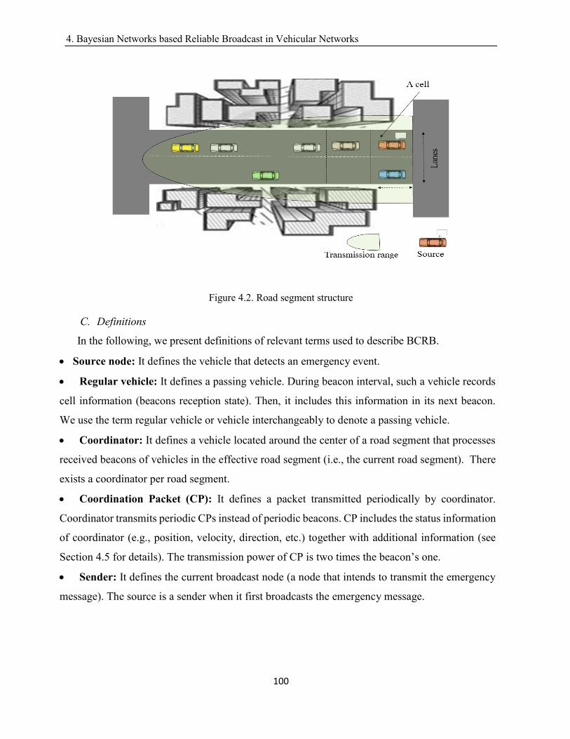
4. Bayesian Networks based Reliable Broadcast in Vehicular Networks
100
Figure 4.2. Road segment structure
C. Definitions
In the following, we present definitions of relevant terms used to describe BCRB.
Source node: It defines the vehicle that detects an emergency event.
Regular vehicle: It defines a passing vehicle. During beacon interval, such a vehicle records
cell information (beacons reception state). Then, it includes this information in its next beacon.
We use the term regular vehicle or vehicle interchangeably to denote a passing vehicle.
Coordinator: It defines a vehicle located around the center of a road segment that processes
received beacons of vehicles in the effective road segment (i.e., the current road segment). There
exists a coordinator per road segment.
Coordination Packet (CP): It defines a packet transmitted periodically by coordinator.
Coordinator transmits periodic CPs instead of periodic beacons. CP includes the status information
of coordinator (e.g., position, velocity, direction, etc.) together with additional information (see
Section 4.5 for details). The transmission power of CP is two times the beacon’s one.
Sender: It defines the current broadcast node (a node that intends to transmit the emergency
message). The source is a sender when it first broadcasts the emergency message.
4. Bayesian Networks based Reliable Broadcast in Vehicular Networks
101
Target area: It defines the geographical area that includes all vehicles approaching/driving,
towards the source, that are intended recipients of the emergency message generated by the source
node.
Uni-Polar Orthogonal Codes (UPOC) [47]: It defines a group of (0, 1) sequence with good
cross-correlation property (i.e, Cross-correlation is a measure of similarity of two (0, 1)
sequences).
D. Overview
The goal of BCRB is to determine optimal number of message repetitions and multiple
forwarders and their positions in order to satisfy reliability requirement at each hop. BCRB
consists of an initialization phase, called Interference Suppression (I-Suppression), and 5 key
phases: (1) Training data collection (TDC); (2) Graphical model learning (GML); (3) Broadcast
Reliability (BR); (4) Forwarders selection (FS); and (5) Cooperative reliability (C-reliability). I-
Suppression is executed once to assign, for each road segment, a Uni-polar orthogonal code
(UPOC) while ensuring zero-correlation between adjacent road segments. TDC and GML run
continuously whereas BR, FS and C-reliability run only when an event requiring an emergency
message to be disseminated to vehicles in a target area occurs. It is worth noting that BCRB is
also applicable for safety applications that rely on one-hop message broadcast. In this context,
FS and C-reliability phases are omitted.
(1) TDC: It is executed by regular vehicles and coordinator of same road segment. More
specifically, a vehicle passing a cell collects reception-state (i.e., beacon reception is
successful or not) information of that cell. Then, it includes this information in its next
beacon. Coordinator processes received beacons with the objective to form training
database.
(2) GML: It is executed by coordinator. Coordinator exploits training database to estimate
link reception quality of 802.11p wireless link in cells; then, it includes this information
in next CP.
(3) BR: It is executed by the source and forwarders. Using recent received CPs, the source
(or the forwarders) computes optimal number of broadcast repetitions that satisfy
reliability requirements in its transmission range.
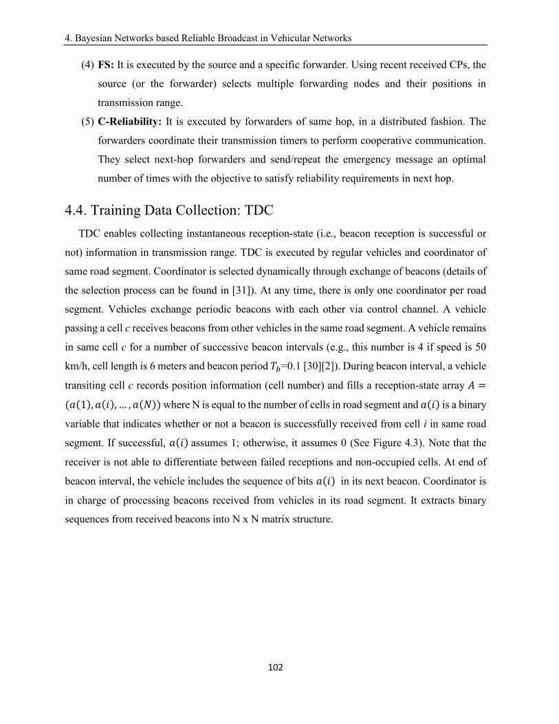
4. Bayesian Networks based Reliable Broadcast in Vehicular Networks
102
(4) FS: It is executed by the source and a specific forwarder. Using recent received CPs, the
source (or the forwarder) selects multiple forwarding nodes and their positions in
transmission range.
(5) C-Reliability: It is executed by forwarders of same hop, in a distributed fashion. The
forwarders coordinate their transmission timers to perform cooperative communication.
They select next-hop forwarders and send/repeat the emergency message an optimal
number of times with the objective to satisfy reliability requirements in next hop.
4.4. Training Data Collection: TDC
TDC enables collecting instantaneous reception-state (i.e., beacon reception is successful or
not) information in transmission range. TDC is executed by regular vehicles and coordinator of
same road segment. Coordinator is selected dynamically through exchange of beacons (details of
the selection process can be found in [31]). At any time, there is only one coordinator per road
segment. Vehicles exchange periodic beacons with each other via control channel. A vehicle
passing a cell c receives beacons from other vehicles in the same road segment. A vehicle remains
in same cell c for a number of successive beacon intervals (e.g., this number is 4 if speed is 50
km/h, cell length is 6 meters and beacon period 𝑇𝑏=0.1 [30][2]). During beacon interval, a vehicle
transiting cell c records position information (cell number) and fills a reception-state array 𝐴 =
(𝑎(1), 𝑎(𝑖),… , 𝑎(𝑁)) where N is equal to the number of cells in road segment and 𝑎(𝑖) is a binary
variable that indicates whether or not a beacon is successfully received from cell i in same road
segment. If successful, 𝑎(𝑖)assumes 1; otherwise, it assumes 0 (See Figure 4.3). Note that the
receiver is not able to differentiate between failed receptions and non-occupied cells. At end of
beacon interval, the vehicle includes the sequence of bits 𝑎(𝑖) in its next beacon. Coordinator is
in charge of processing beacons received from vehicles in its road segment. It extracts binary
sequences from received beacons into N x N matrix structure.
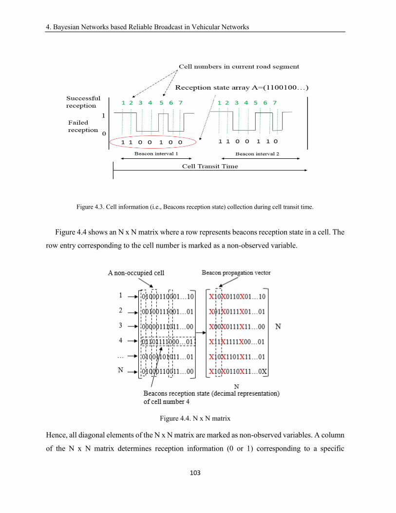
4. Bayesian Networks based Reliable Broadcast in Vehicular Networks
103
Figure 4.3. Cell information (i.e., Beacons reception state) collection during cell transit time.
Figure 4.4 shows an N x N matrix where a row represents beacons reception state in a cell. The
row entry corresponding to the cell number is marked as a non-observed variable.
Figure 4.4. N x N matrix
Hence, all diagonal elements of the N x N matrix are marked as non-observed variables. A column
of the N x N matrix determines reception information (0 or 1) corresponding to a specific
4. Bayesian Networks based Reliable Broadcast in Vehicular Networks
104
broadcasted beacon; a column with only zero entries represents a non-occupied cell. Coordinator
marks entries of rows corresponding to non-occupied cells as non-observed variables. Note that
entries of a row/column corresponding to a non-occupied cell are marked with the symbol x to
indicate a non-observed variable. Then, the matrix entries (i.e., observed ones) are included in the
training data. A row of the N x N matrix represents a training sample. Each beacon period, there
are 𝑁𝑔 ≤ 𝑁 observed variables (training samples) added to the training data. Size of training data
(in terms of number of observed variables) depends on both TDC phase duration and nodes
density. Coordinator uses the training data to train a Bayesian Network in GML phase.
4.5. Graphical Model Learning: GML
Coordinator, of a road segment, executes GML to estimate link reception quality in
transmission range using Bayesian networks. A Bayesian network is a directed, acyclic graph that
discovers and represents dependencies, among random variables from observational data [110]. It
represents the causal relationships between uncertain events. Using this property, coordinator
predicts/estimates the 802.11p link reception quality in each cell. The 802.11p link reception
quality can't be predicted/estimated with total certainty. Using probability, coordinator can
estimate how likely message reception event is to happen. Bayes' Theorem is used to quantify
uncertainty [110]. Indeed, by hypothesizing that link reception quality in a cell is good (i.e.,
successful packet reception), the theorem defines a rule for refining such a hypothesis; It factors
an additional evidence E (an observed data) and a background information 𝜃 (a prior knowledge).
The result represents the probability that the hypothesis is true:
p(E|θ) =p(θ|E) × p(θ)
p(E)(1)
Let N be the number of cells in transmission range, and 𝑋𝑖 ∈ 𝜓(0 ≤ 𝑖 ≤ 𝑁) be a random
variable associated with cell i (a possible receiver i) assuming 0 or 1. For each random variable
𝑋𝑖, coordinator has to compute the probabilities 𝑝(𝑋𝑖 = 1) and 𝑝(𝑋𝑖 = 0). Let 𝑋𝑖be a Bernoulli
random variable 𝑋𝑖~𝛽(𝑝𝑖(𝑥)) with reception probability 𝑝𝑖 ∈ 𝜁 ; in this paper, we consider that
reception probability 𝑝𝑖 = 𝑝(𝑋𝑖 = 1), is the 802.11p wireless link reception quality in cell i.
Coordinator explores the possibility of causal relationships between adjacent cells , using
Bayesian network, in order to accurately estimate/predict reception probability 𝑝𝑖. To build
4. Bayesian Networks based Reliable Broadcast in Vehicular Networks
105
Bayesian network, in current road segment, coordinator learns causal relationships (i.e., the graph
structure) and the probabilities (i.e., parameters) from training data (i.e., output of TDC). Let
ℊ(𝜓, 𝜁) denote Bayesian network (a graph and its associated parameters), where 𝜓 represents the
set of random variables and 𝜁 represents conditional probability tables. Coordinator determines
joint probability distribution of link reception qualities; it can be expressed as follows;
P(X1, X2, … , XN) = ∏p(
k=N
k=1
Xk|pa(Xk))(2)
where p(Xk|pa(Xk)) is the local conditional probability distribution associated with receiver k
and pa(Xk)is the set of indices labeling the parents of node k; pa(Xk) can be empty if node k has
no parent [40].
Learning graph structure
In this paper, we use a constraint-based search technique, namely the widely used PC (Peter-
Clark) [111], which searches through possible graph structures to learn the graph structure. PC
consists of three main steps: (a) Construct a non-direct graph using conditional independence and
independence tests; (b) Determine V-structures (Note that a V-structure is an ordered tuple
(X,Y,Z) such that there is an arc from X to Y and from Z to Y, but no arc between X and Z); and
(c) Propagate direction of some arcs. It starts with an initial completed graph structure. Then, it
performs the three steps to find out relations among nodes using both independence tests and
conditional independence tests [112]. In this paper, we propose a modified version of PC
algorithm, called V-PC, adapted to vehicular network.
(a) Initial graph structure
In vehicular networks, starting from a complete graph results in an exhaustive search in the space
of possible graph structures which is not practical. For three lanes road segment, we have 50 cells
per lane and 150 cells per road segment. Hence, there is |𝜓| =150 random variables to model
links reception quality in the road segment. The total number of graph structures is huge.
Furthermore, even though direct or indirect relations among all random variables (cells) in
transmission range exist, it is very difficult to directly describe the causality relationship between
all cells. The search algorithm has to determine causality relationships between too many
variables. To overcome this, we assume that any cell is conditionally independent of its non-
4. Bayesian Networks based Reliable Broadcast in Vehicular Networks
106
adjacent cells given its adjacent cells, i.e., there is no direct influence between a cell and its non-
adjacent cells. The proposed assumption simplifies the relation among cells in transmission range.
Furthermore, it nicely fits the assumption of the local Markov rule [113] required when modelling
with Bayesian networks. The Markov rule specifies that variable 𝑋𝑘 is independent of its non-
descendants given its parents; it is expressed as follows:
(Xk ⊥ pa(Xk̅̅ ̅̅ ̅̅ ̅̅ ))|pa(Xk)(3)
With this assumption, the complexity of graph learning algorithm is significantly reduced. Let
𝑋�̃�(1 ≤ 𝑘 ≤ 𝑁) denote the set of descendants and ancestors of cell 𝑋𝑘.Using Equation (3), 𝑋𝑘is
independent of the remaining nodes in the graph given 𝑋�̃�. The local probability distribution table
of 𝑋k(1 ≤ 𝑘 ≤ 𝑁) can be expressed as follows:
p(Xk|X1, X2, … , Xk−1, Xk+1, … , XN) = p(Xk|Xk̃)(4)
Consequently, the joint probability distribution can be recovered using only conditional
probability distributions. In the context of vehicular networks, the proposed assumption fits well
with the training data. Indeed, vehicles tend to move in small groups of 4-6 adjacent vehicles,
especially when density is small [114]. Figure 4.5 shows initial graph structure for three lanes
road segment. Edges between non-adjacent cells are omitted. A node in the graph has at most 8
adjacent nodes. To construct an initial graph, coordinator uses a graph indexing method. Nodes in
the graph represent cells in transmission range, labeled by cell numbers. Rows represent street
lanes. Columns represent the road segment blocks (a block represents a portion of the road
segment such that block-length is 6 m) from 1 to ⌈300
6⌉. A cell, located in the intersection of row y
and column x, is assigned cell number i computed as follows:
𝑖 = 𝑦 × 𝐿 − (𝐿 − 𝑥)(5)
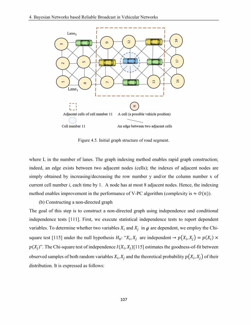
4. Bayesian Networks based Reliable Broadcast in Vehicular Networks
107
Figure 4.5. Initial graph structure of road segment.
where L in the number of lanes. The graph indexing method enables rapid graph construction;
indeed, an edge exists between two adjacent nodes (cells); the indexes of adjacent nodes are
simply obtained by increasing/decreasing the row number y and/or the column number x of
current cell number i, each time by 1. A node has at most 8 adjacent nodes. Hence, the indexing
method enables improvement in the performance of V-PC algorithm (complexity is ≈ 𝑂(𝑛)).
(b) Constructing a non-directed graph
The goal of this step is to construct a non-directed graph using independence and conditional
independence tests [111]. First, we execute statistical independence tests to report dependent
variables. To determine whether two variables 𝑋𝑖 and 𝑋𝑗 in ℊ are dependent, we employ the Chi-
square test [115] under the null hypothesis 𝐻0: “𝑋𝑖, 𝑋𝑗 are independent→ 𝑝(𝑋𝑖 , 𝑋𝑗) = 𝑝(𝑋𝑖) ×
𝑝(𝑋𝑗)”. The Chi-square test of independence 𝐼(𝑋𝑖, 𝑋𝑗)[115] estimates the goodness-of-fit between
observed samples of both random variables 𝑋𝑖, 𝑋𝑗and the theoretical probability 𝑝(𝑋𝑖, 𝑋𝑗)of their
distribution. It is expressed as follows:
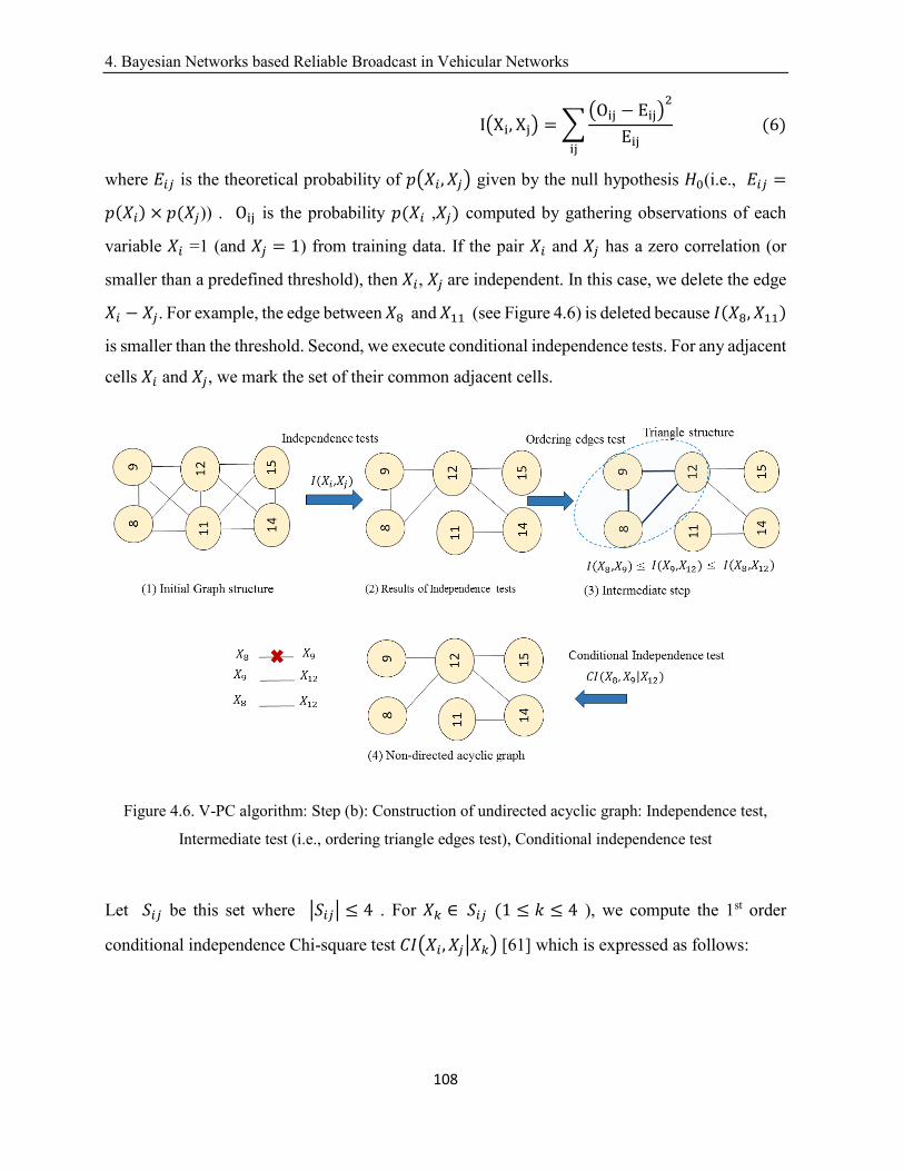
4. Bayesian Networks based Reliable Broadcast in Vehicular Networks
108
I(Xi, Xj) = ∑(Oij − Eij)
2
Eijij
(6)
where 𝐸𝑖𝑗 is the theoretical probability of 𝑝(𝑋𝑖, 𝑋𝑗) given by the null hypothesis 𝐻0(i.e., 𝐸𝑖𝑗 =
𝑝(𝑋𝑖) × 𝑝(𝑋𝑗)) . Oij is the probability 𝑝(𝑋𝑖 ,𝑋𝑗) computed by gathering observations of each
variable 𝑋𝑖 =1 (and 𝑋𝑗 = 1) from training data. If the pair 𝑋𝑖 and 𝑋𝑗 has a zero correlation (or
smaller than a predefined threshold), then 𝑋𝑖, 𝑋𝑗are independent. In this case, we delete the edge
𝑋𝑖 − 𝑋𝑗. For example, the edge between 𝑋8 and 𝑋11 (see Figure 4.6) is deleted because 𝐼(𝑋8, 𝑋11)
is smaller than the threshold. Second, we execute conditional independence tests. For any adjacent
cells 𝑋𝑖 and 𝑋𝑗, we mark the set of their common adjacent cells.
Figure 4.6. V-PC algorithm: Step (b): Construction of undirected acyclic graph: Independence test,
Intermediate test (i.e., ordering triangle edges test), Conditional independence test
Let 𝑆𝑖𝑗 be this set where |𝑆𝑖𝑗| ≤ 4 . For 𝑋𝑘 ∈ 𝑆𝑖𝑗 (1 ≤ 𝑘 ≤ 4 ), we compute the 1st order
conditional independence Chi-square test 𝐶𝐼(𝑋𝑖, 𝑋𝑗|𝑋𝑘) [61] which is expressed as follows:

4. Bayesian Networks based Reliable Broadcast in Vehicular Networks
109
CI(Xi, Xj|Xk) = ∑(O𝑖𝑗𝑘 − 𝐸𝑖𝑗𝑘)
2
𝐸𝑖𝑗𝑘𝑖𝑗𝑘
(7)
where 𝐸𝑖𝑗𝑘 is the theoretical probability given by the null hypothesis 𝐻0 “𝑋𝑖 and 𝑋𝑗 are
independent given 𝑋𝑘 ⇒ 𝑝(𝑋𝑖, 𝑋𝑗|𝑋𝑘) = 𝑝(𝑋𝑖|𝑋𝑘) × 𝑝(𝑋𝑗|𝑋𝑘) “.O𝑖𝑗𝑘 represents probability
distribution of 𝑋𝑖 and 𝑋𝑗 conditioned on 𝑋𝑘computed from training data. If the pair (𝑋𝑖 , 𝑋𝑗)
conditioned on 𝑋𝑘has zero correlation (or smaller than a predefined threshold), the edge 𝑋𝑖 − 𝑋𝑗
is deleted. This process continues for 2nd and 3rd orders. However, it is important to note that the
order in which conditional independence tests are carried out impacts the structure of non-direct
graph (e.g., in Figure 4.6, if conditional independence 𝐶𝐼(𝑋8, 𝑋9|𝑋12) is carried first, the edge
𝑋8 − 𝑋9 may be deleted; if 𝐶𝐼(𝑋9, 𝑋12|𝑋8) is carried first, the edge 𝑋9 − 𝑋12 may be deleted).
In this paper, if one of the edges is going to be removed, we choose the weakest, in terms of
dependence, one (i.e., with smallest value).
More specifically, we propose to add an intermediate test between independence tests and
conditional independence tests called ordering triangle edges test. For each three variables 𝑋𝑖, 𝑋𝑗
and 𝑋𝑘 that form a triangle, we measure the strength of dependence between all the three pairs of
variables (i.e., 𝑋𝑖 − 𝑋𝑗, 𝑋𝑗 − 𝑋𝑘 and 𝑋𝑘 − 𝑋𝑖 ) using Equation (4); then, we conduct conditional
independence test on the weakest edge. Hence, the weakest edge will be deleted if the conditional
independence Chi-square test is smaller than the threshold. Otherwise, we conduct conditional
independence test on the next weakest edge, and so on. For each selected node in the graph,
conditional dependence test and/or conditional independence test are performed with 8 adjacent
nodes. V-PC algorithm locates adjacent cells in the graph using a graph indexing method (see
Figure 4.5). In the worst case scenario, the complexity of this step is ≈ 𝑂(8 × 𝑛) ≈ 𝑂(𝑛).
(c) Determine V-structures
For each connected triplet(𝑋𝑖, 𝑋𝑗, 𝑋𝑘), coordinator directs the arcs and adds a V-structure [112]
as follows: 𝑋𝑖 → 𝑋𝑗 ← 𝑋𝑘. The complexity of this step is 𝑂(83 × 𝑛) ≈ 𝑂(𝑛).
(d) Propagate direction of some arcs
Coordinator directs remaining arcs in a way that avoids the creation of new V-structures and
cycles [112]. The complexity of this step is 𝑂(𝑛).
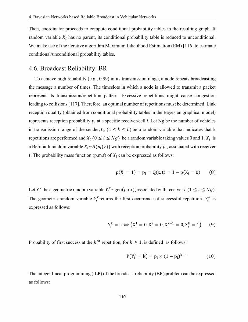
4. Bayesian Networks based Reliable Broadcast in Vehicular Networks
110
Then, coordinator proceeds to compute conditional probability tables in the resulting graph. If
random variable 𝑋𝑖 has no parent, its conditional probability table is reduced to unconditional.
We make use of the iterative algorithm Maximum Likelihood Estimation (EM) [116] to estimate
conditional/unconditional probability tables.
4.6. Broadcast Reliability: BR
To achieve high reliability (e.g., 0.99) in its transmission range, a node repeats broadcasting
the message a number of times. The timeslots in which a node is allowed to transmit a packet
represent its transmission/repetition pattern. Excessive repetitions might cause congestion
leading to collisions [117]. Therefore, an optimal number of repetitions must be determined. Link
reception quality (obtained from conditional probability tables in the Bayesian graphical model)
represents reception probability 𝑝𝑖at a specific receiver/cell i. Let Ng be the number of vehicles
in transmission range of the sender, 𝑡𝑘 (1 ≤ 𝑘 ≤ 𝐿)be a random variable that indicates that k
repetitions are performed and 𝑋𝑖(0 ≤ 𝑖 ≤ 𝑁𝑔) be a random variable taking values 0 and 1. 𝑋𝑖is
a Bernoulli random variable 𝑋𝑖~𝐵(𝑝𝑖(𝑥)) with reception probability 𝑝𝑖, associated with receiver
𝑖. The probability mass function (p.m.f) of 𝑋𝑖 can be expressed as follows:
p(Xi = 1) = pi = Q(x, t) = 1 − p(Xi = 0)(8)
Let 𝑌𝑖𝑘 be a geometric random variable 𝑌𝑖
𝑘~geo(𝑝𝑖(𝑥))associated with receiver i, (1 ≤ 𝑖 ≤ 𝑁𝑔).
The geometric random variable 𝑌𝑖𝑘returns the first occurrence of successful repetition. 𝑌𝑖
𝑘 is
expressed as follows:
Yik = k ⟺ (Xi
1 = 0, Xi2 = 0, Xi
k−1 = 0, Xik = 1)(9)
Probability of first success at the 𝑘𝑡ℎ repetition, for 𝑘 ≥ 1, is defined as follows:
P(Yik = k) = pi × (1 − pi)
k−1(10)
The integer linear programming (ILP) of the broadcast reliability (BR) problem can be expressed
as follows:
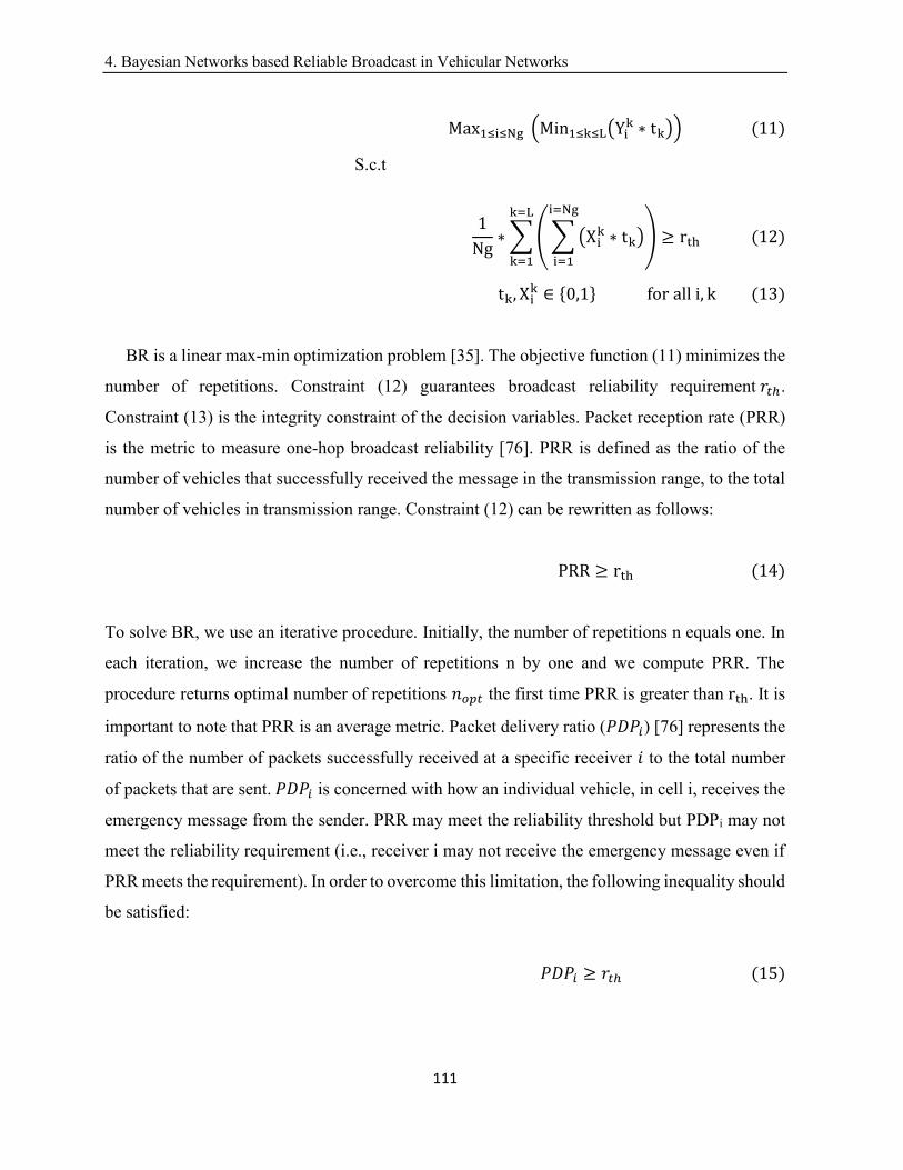
4. Bayesian Networks based Reliable Broadcast in Vehicular Networks
111
Max1≤i≤Ng (Min1≤k≤L(Yik ∗ tk))(11)
S.c.t
1
Ng∗ ∑(∑(Xi
k ∗ tk)
i=Ng
i=1
)
k=L
k=1
≥ rth(12)
tk, Xik ∈ {0,1}foralli, k(13)
BR is a linear max-min optimization problem [35]. The objective function (11) minimizes the
number of repetitions. Constraint (12) guarantees broadcast reliability requirement𝑟𝑡ℎ.
Constraint (13) is the integrity constraint of the decision variables. Packet reception rate (PRR)
is the metric to measure one-hop broadcast reliability [76]. PRR is defined as the ratio of the
number of vehicles that successfully received the message in the transmission range, to the total
number of vehicles in transmission range. Constraint (12) can be rewritten as follows:
PRR ≥ rth(14)
To solve BR, we use an iterative procedure. Initially, the number of repetitions n equals one. In
each iteration, we increase the number of repetitions n by one and we compute PRR. The
procedure returns optimal number of repetitions 𝑛𝑜𝑝𝑡 the first time PRR is greater thanrth. It is
important to note that PRR is an average metric. Packet delivery ratio (𝑃𝐷𝑃𝑖) [76] represents the
ratio of the number of packets successfully received at a specific receiver 𝑖 to the total number
of packets that are sent.𝑃𝐷𝑃𝑖 is concerned with how an individual vehicle, in cell i, receives the
emergency message from the sender. PRR may meet the reliability threshold but PDPi may not
meet the reliability requirement (i.e., receiver i may not receive the emergency message even if
PRR meets the requirement). In order to overcome this limitation, the following inequality should
be satisfied:
𝑃𝐷𝑃𝑖 ≥ 𝑟𝑡ℎ(15)
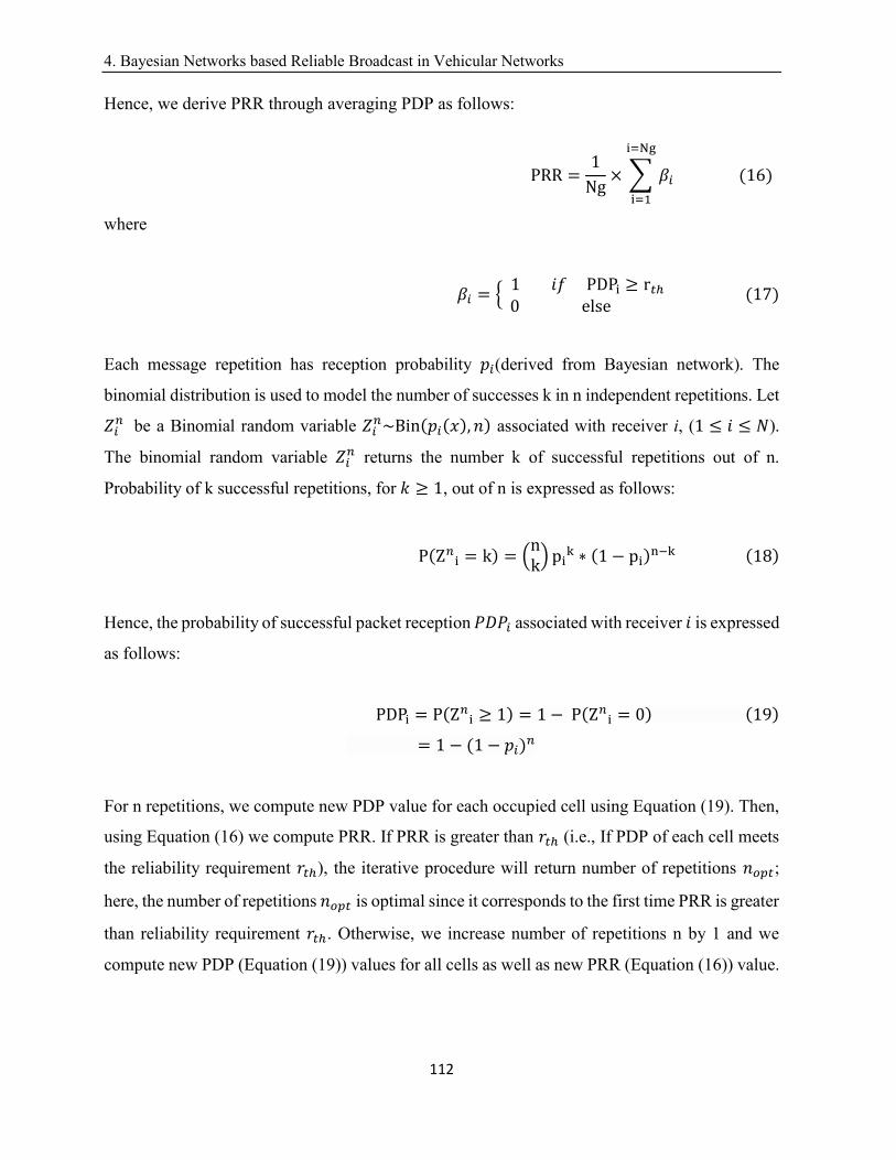
4. Bayesian Networks based Reliable Broadcast in Vehicular Networks
112
Hence, we derive PRR through averaging PDP as follows:
PRR =1
Ng× ∑ 𝛽𝑖
i=Ng
i=1
(16)
where
𝛽𝑖 = {1𝑖𝑓PDPi ≥ r𝑡ℎ0else
(17)
Each message repetition has reception probability 𝑝𝑖(derived from Bayesian network). The
binomial distribution is used to model the number of successes k in n independent repetitions. Let
𝑍𝑖𝑛 be a Binomial random variable 𝑍𝑖
𝑛~Bin(𝑝𝑖(𝑥), 𝑛) associated with receiver i, (1 ≤ 𝑖 ≤ 𝑁).
The binomial random variable 𝑍𝑖𝑛 returns the number k of successful repetitions out of n.
Probability of k successful repetitions, for 𝑘 ≥ 1, out of n is expressed as follows:
P(Z𝑛i = k) = (
nk) pi
k ∗ (1 − pi)n−k(18)
Hence, the probability of successful packet reception 𝑃𝐷𝑃𝑖 associated with receiver 𝑖 is expressed
as follows:
PDPi = P(Z𝑛i ≥ 1) = 1 − P(Z𝑛
i = 0)(19)
= 1 − (1 − 𝑝𝑖)𝑛
For n repetitions, we compute new PDP value for each occupied cell using Equation (19). Then,
using Equation (16) we compute PRR. If PRR is greater than 𝑟𝑡ℎ (i.e., If PDP of each cell meets
the reliability requirement 𝑟𝑡ℎ), the iterative procedure will return number of repetitions 𝑛𝑜𝑝𝑡;
here, the number of repetitions 𝑛𝑜𝑝𝑡is optimal since it corresponds to the first time PRR is greater
than reliability requirement 𝑟𝑡ℎ. Otherwise, we increase number of repetitions n by 1 and we
compute new PDP (Equation (19)) values for all cells as well as new PRR (Equation (16)) value.
4. Bayesian Networks based Reliable Broadcast in Vehicular Networks
113
4.7. Interference Suppression: I-Suppression
In BCRB, repetition patterns are obtained using UPOC [47] with the objective to decrease,
ideally avoid, interference caused by hidden terminal problem. Let 𝜉 = (𝐿,𝜛, 𝜆) be a set of
UPOCs, where L is the code length, 𝜛 is the code weight and 𝜆 is the cross-correlation [47]. Let
x= (𝑥1, 𝑥2, … , 𝑥𝐿) and y= (𝑦1, 𝑦2, … , 𝑦𝐿) ∈ 𝜉 be two codes such that 𝑥 ≠ 𝑦. Let 𝜏 (1 ≤ 𝜏 ≤ 𝐿 −
1)be a circular displacement. The cross-correlation property is defined as follows:
∑xi ∗ yi⨁τ
L−1
0
≤ λ(20)
In order to time-separate interfering nodes, each road segment is assigned a specific code
(repetition pattern). A repetition pattern represents a binary sequence of length L in which bit 1
denotes a transmission and bit 0 denotes a non-transmission. In each timeslot, if a node is not
transmitting, it is in the idle mode. The code assignment scheme must ensure that cross-
correlation property 𝜆(0 ≤ 𝜆 ≤ 𝜛 − 1) with 2-hop neighboring nodes is zero. In a city streets
grid-plan, length of a road segment is in average smaller than 500 meters [118][119]. More
specifically, a node along a route can interfere with vehicles located in up to 8 adjacent road
segments (4 parallel road segments and 4 perpendicular road segments). In this situation, at least
9 codes (i.e., |𝜉| = 9) having zero correlation are required. Johnson [87] provides an upper bound
for the size of codes |𝜉|.
|𝜉| ≤ ⌊𝐿
𝜛× ⌊
𝐿 − 1
𝜛 − 1× …× ⌊
𝐿 − 𝜆
𝜆⌋⌋⌋(21)
where ⌊𝑎⌋ is the biggest integer smaller than or equal to a. The zero cross correlation property
results in a small number of codes |𝜉| [47] (Note that strict orthogonality, i.e., λ = 0, leads to a
very low code cardinality, namely, at most 𝐿
𝜛). In addition, the cross-correlation constraint for a
set of codes is always equal to 1 [47]. Hence, in this paper, cross-correlation property 𝜆is set to
1(𝑖. 𝑒. ⌊𝐿
𝜛× ⌊
𝐿−1
𝜛−1⌋⌋). In a repetition pattern, one collided repetition is allowed without affecting
the reliability requirement. Hence, the code weight 𝜛 is set to the maximum number of repetitions
4. Bayesian Networks based Reliable Broadcast in Vehicular Networks
114
in a frame plus one (because cross-correlation property 𝜆 = 1 ). To compute 𝜛 , we determine
maximum number of repetitions that achieves reliability requirement 𝑟𝑡ℎ. If we assume, that for
cell i, 𝑝𝑖 =0.25 (e.g., very low reception probability) and 𝑟𝑡ℎ=0.99, then number of repetitions
will be 14 (i.e., using Equation (19): 1 − (1 − 0.25)𝑛 = 0.99 ⇒ 𝑛 ≈ 14). In this case, code
weight 𝜛 ≈ 15(= 14 + 1). In a frame, a collision can occur only in one time slot without
reliability penalty. A vehicle joining a road segment gets the repetition pattern. Once an event
occurs, the vehicle computes its optimal number of repetitions 𝑛𝑜𝑝𝑡 (See section 4.6). Then, it
maps this number to the repetition pattern of its current road segment. The vehicle uses first
𝑛𝑜𝑝𝑡 + 1 transmission slots (bit 1) out of𝜛 transmission slots. To perform repetitions, we design
an overlay, called MAC Repetition Layer (MRL), on the standard MAC Carrier Sensing [38].
MRL is responsible for generating broadcast repetitions. MRL resides between standard MAC
layer and Logical Link Control (LLC) layer. The proposed repetition design is compatible with
the 802.11 distributed Coordination function (DCF) (no handshake for repetitions, etc.). This
makes the proposed repetition scheme compatible with the emerging standards [2] (i.e., IEEE
802.11p amendment for wireless access in vehicular environments (WAVE)) for DSRC [38].
4.8. Forwarders Selection: FS
To relay the message to next hop, BCRB selects multiple next-hop forwarders having best
link reception qualities. Multiple forwarders allow avoiding single forwarder limitations; if only
one vehicle is chosen as a forwarder and if that vehicle malfunctions or moves away (i.e., leaves
the road segment) the message dissemination will be stopped. Let 𝑛𝐹 be the number of
forwarders. For simplification, we take number of repetitions 𝑛𝑜𝑝𝑡 as a reasonable value for 𝑛𝐹.
To ensure successful message reception, forwarders should have high reception probability.
Furthermore, it is a known fact that forwarders locations should be close to the border in order
to reduce multi-hop latency. First, the sender makes use of link reception quality information to
select forwarders. Forwarders having good link reception quality are better choices to
successfully receive the message and retransmit it. Consider neighbors’ information is available
(i.e., using exchanged beacons). Let 𝑣𝑁𝑔 denote the set of cells in transmission range having
vehicles. For each 𝑥 ∈ 𝑣𝑁𝑔 , the sender extracts the corresponding link reception quality from
the most recent CP packet and picks the best 𝑛𝐹 elements of 𝑣𝑁𝑔 (in terms of link reception
quality); then, it creates a set 𝑣𝑞 that includes these elements ordered from best to worst (in terms
4. Bayesian Networks based Reliable Broadcast in Vehicular Networks
115
of link reception quality). Second, the sender ensures that the locations of forwarders are close
to the border of the transmission range. To achieve this, for each location 𝑥 ∈ 𝑣𝑞 , the sender
makes use of a location-shifting technique 𝜏(𝑥) that moves 𝑥to the closest location y to the
border while preserving an equivalent (or rather almost equivalent) link reception quality. Let 𝑣𝐹
denote the set of resulting forwarders locations. The sender applies a prioritization rule 𝜑𝑖(1 ≤
𝑖 ≤ 𝑛𝐹) to forwarders locations in 𝑣𝐹. 𝜑𝑖 is defined as follows:
𝜑𝑖 = 𝜑(𝑣𝐹(𝑖)) = 𝑖(22)
The locations of forwarders and their priorities 𝜑𝑖 are included in the emergency message. Such
information is useful to coordinate among forwarders in the C-reliability phase.
4.9. Cooperative Reliability: C-Reliability
This phase is executed by forwarders of same hop. The forwarders cooperatively perform
optimal broadcast repetitions with the objective to reinforce achieving high broadcast reliability.
In addition, the forwarders coordinate to select next-hop forwarders. To achieve this, the
forwarders take the role of broadcasting the message iteratively with respect to their priorities 𝜑𝑖
. Each forwarder 𝑗 (1 ≤ 𝑗 ≤ 𝑛𝐹) is assigned a broadcasting timer Tac(j) and its initial value is
indicated in Equation (23). If the broadcasting timer expires, corresponding forwarder 𝑗 performs
nre(𝑗) repetitions; initial number of repetitions is indicated in Equation (25). Otherwise, the
corresponding forwarder is suspended and the value of its broadcasting timer is updated using
Equation (24). Similarly, the number of repetitions per forwarder is updated using Equation (26).
Initially, highest priority forwarder (with max𝑖
𝜑𝑖) executes broadcast repetitions (BR) and selects
next-hop forwarders while forwarders at lower priorities are suspended. Lower priority
forwarders overhear message transmissions and record failed receptions as specified in Equation
(26) as long as their broadcasting timer is not expired. Indeed, the repetitions are either
successfully transmitted or lost before broadcasting timer of forwarder j expires. If broadcasting
timer 𝑇𝑎𝑐(𝑗) of forwarder j expires, we distinguish three cases:
(a) Case 1:
4. Bayesian Networks based Reliable Broadcast in Vehicular Networks
116
Current forwarder j failed to receive all repetitions of higher priority forwarder(s) (nre(𝑗) =
𝑛𝑜𝑝𝑡). This means that higher priority forwarders are malfunctioning or have moved away. Thus,
current forwarder j executes forwarders selection (FS) before broadcasting the repetitions.
(b) Case 2:
Current forwarder j successfully received all repetitions of higher priority forwarders
(nre(j) = 0). In this case, current forwarder j remains in idle state and suspends its broadcasting
timer.
(c) Case 3:
Current forwarder j didn’t successfully receive all repetitions of higher-priority forwarders (
𝑛𝐹 > nre(j) > 0). This situation usually occurs when higher-priority forwarders leave the
transmission range before accomplishing 𝑛𝑜𝑝𝑡repetitions. Thus, current forwarder j extracts
next-hop forwarders list from the already successfully received repetitions and carries out the
rest of repetitions as specified in Equation (26).
As long as Equation (28) is not verified, the reliability requirement in current hop is not
achieved and the coordination process among forwarders continues.
Tac(j) = TFS + nopt ∗ TData(23)
Tac(j) = (j − 1) ∗ ∆sj + n𝑟𝑒(j) ∗ TData(24)
nre(𝑗) = n𝑜𝑝𝑡(25)
𝑛𝑟𝑒(𝑗) = 𝑛𝑜𝑝𝑡 − (∑(𝑛𝑜𝑝𝑡 − nre(i − 1))
𝑖=𝑗
𝑖=3
)(26)
𝑛𝑟𝑒(𝑗) = 𝑛𝑟𝑒(𝑗) + 1(27)
𝑛𝑜𝑝𝑡 =(∑nre(i)
𝑖=𝑗
𝑖=1
)(28)
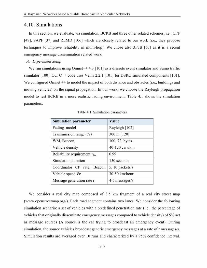
4. Bayesian Networks based Reliable Broadcast in Vehicular Networks
117
4.10. Simulations
In this section, we evaluate, via simulation, BCRB and three other related schemes, i.e., CPF
[49], SAPF [37] and REMD [106] which are closely related to our work (i.e., they propose
techniques to improve reliability in multi-hop). We chose also 3P3B [63] as it is a recent
emergency message dissemination related work.
A. Experiment Setup
We run simulations using Omnet++ 4.3 [101] as a discrete event simulator and Sumo traffic
simulator [100]. Our C++ code uses Veins 2.2.1 [101] for DSRC simulated components [101].
We configured Omnet ++ to model the impact of both distance and obstacles (i.e., buildings and
moving vehicles) on the signal propagation. In our work, we choose the Rayleigh propagation
model to test BCRB in a more realistic fading environment. Table 4.1 shows the simulation
parameters.
Table 4.1. Simulation parameters
Simulation parameter Value
Fading model Rayleigh [102]
Transmission range (Tr) 300 m [120]
WM, Beacon, 100, 72, bytes.
Vehicle density 40-120 cars/km
Reliability requirement 𝑟𝑡ℎ 0.99
Simulation duration 150 seconds
Coordinator CP rate, Beacon
rate
5, 10 packets/s
Vehicle speed Ve 30-50 km/hour
Message generation rate r 4-5 messages/s
We consider a real city map composed of 3.5 km fragment of a real city street map
(www.openstreetmap.org/). Each road segment contains two lanes. We consider the following
simulation scenario: a set of vehicles with a predefined penetration rate (i.e., the percentage of
vehicles that originally disseminate emergency messages compared to vehicle density) of 5% act
as message sources (A source is the car trying to broadcast an emergency event). During
simulation, the source vehicles broadcast generic emergency messages at a rate of r messages/s.
Simulation results are averaged over 10 runs and characterized by a 95% confidence interval.
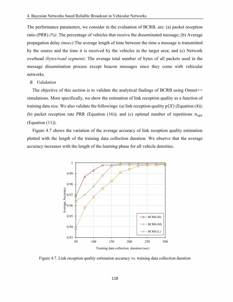
4. Bayesian Networks based Reliable Broadcast in Vehicular Networks
118
The performance parameters, we consider in the evaluation of BCRB, are: (a) packet reception
ratio (PRR) (%): The percentage of vehicles that receive the disseminated message; (b) Average
propagation delay (msec):The average length of time between the time a message is transmitted
by the source and the time it is received by the vehicles in the target area; and (c) Network
overhead (bytes/road segment): The average total number of bytes of all packets used in the
message dissemination process except beacon messages since they come with vehicular
networks.
B. Validation
The objective of this section is to validate the analytical findings of BCRB using Omnet++
simulations. More specifically, we show the estimation of link reception quality as a function of
training data size. We also validate the followings: (a) link reception quality 𝑝(𝑋) (Equation (4));
(b) packet reception rate PRR (Equation (16)); and (c) optimal number of repetitions 𝑛𝑜𝑝𝑡
(Equation (11)).
Figure 4.7 shows the variation of the average accuracy of link reception quality estimation
plotted with the length of the training data collection duration. We observe that the average
accuracy increases with the length of the learning phase for all vehicle densities.
Figure 4.7. Link reception quality estimation accuracy vs. training data collection duration
0.93
0.94
0.95
0.96
0.97
0.98
0.99
1
50 100 150 200 250 300
Aver
age
Acc
ura
cy
Training data collection duration (sec)
BCRB-(H)
BCRB-(M)
BCRB-(L)

4. Bayesian Networks based Reliable Broadcast in Vehicular Networks
119
This can be explained by the fact that the size of training data is proportional to the length of the
training data collection duration; indeed, the number of samples in the training data equals to the
training phase duration, multiplied by both beacons rate and the number of vehicle per road
segment. This is expected since the larger the training data set is, the more accurate the estimated
joint probability distribution will be and the more accurate the conditional probability table
estimation result (link reception quality estimation). Note that, theoretically, there is no
relationship between size of training data and the estimation accuracy. At 175 seconds, the
average estimation accuracy is higher than 99%, for all densities. We refer to such a value as an
optimal learning delay.
Figure 4.8 shows link reception quality 𝑝(𝑋)(taken for optimal training data collection
duration) plotted against vehicle density. As expected, 𝑝(𝑋)decreases when vehicle density
increases. This is expected since traffic of periodic beacons increases with density resulting in
unreliable wireless links. This observation validates the use of 𝑝(𝑋) to assess 802.11p link
reception quality in cells. The analytical results closely follow simulation results for all densities.
In average, the difference between the analytical and the simulation results falls below 2%.
Figure 4.8. Link reception quality vs. density
0
0.2
0.4
0.6
0.8
1
40 60 80 100
lin
k r
ecep
tion
qu
alit
y
Density
BCRB Simulation
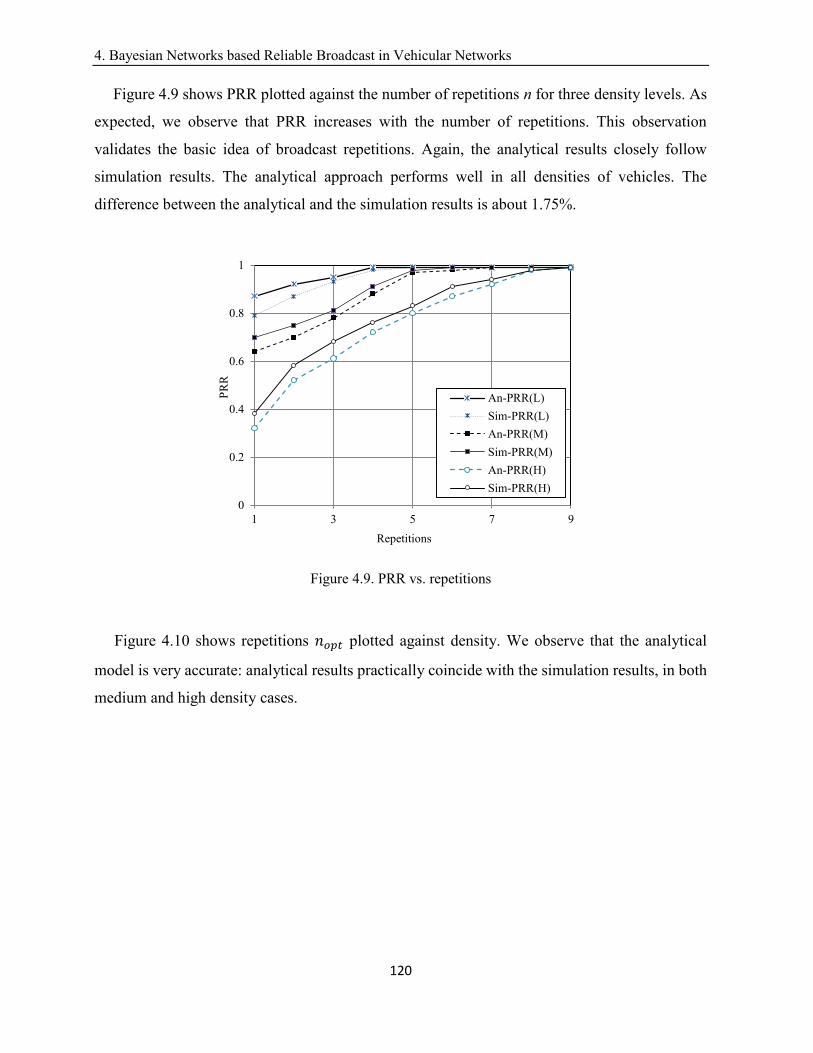
4. Bayesian Networks based Reliable Broadcast in Vehicular Networks
120
Figure 4.9 shows PRR plotted against the number of repetitions n for three density levels. As
expected, we observe that PRR increases with the number of repetitions. This observation
validates the basic idea of broadcast repetitions. Again, the analytical results closely follow
simulation results. The analytical approach performs well in all densities of vehicles. The
difference between the analytical and the simulation results is about 1.75%.
Figure 4.9. PRR vs. repetitions
Figure 4.10 shows repetitions 𝑛𝑜𝑝𝑡 plotted against density. We observe that the analytical
model is very accurate: analytical results practically coincide with the simulation results, in both
medium and high density cases.
0
0.2
0.4
0.6
0.8
1
1 3 5 7 9
PR
R
Repetitions
An-PRR(L)
Sim-PRR(L)
An-PRR(M)
Sim-PRR(M)
An-PRR(H)
Sim-PRR(H)
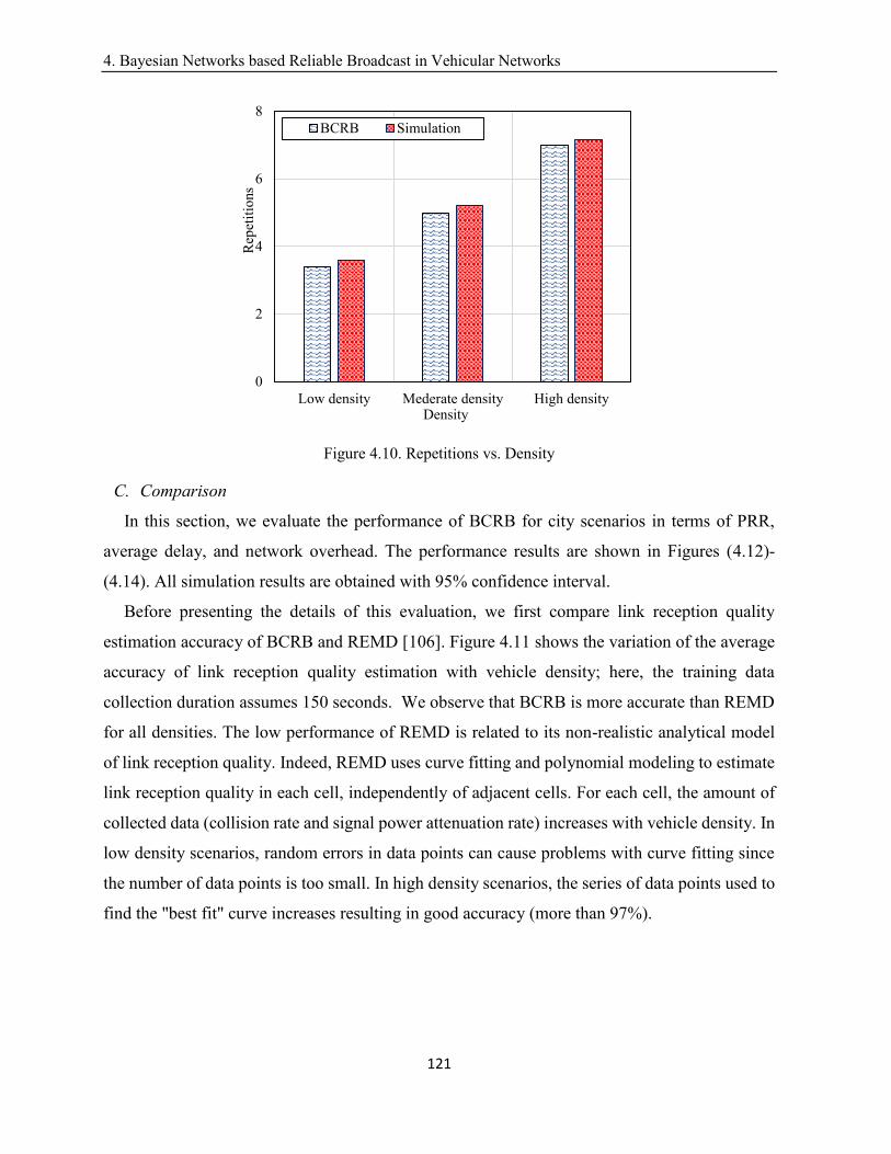
4. Bayesian Networks based Reliable Broadcast in Vehicular Networks
121
Figure 4.10. Repetitions vs. Density
C. Comparison
In this section, we evaluate the performance of BCRB for city scenarios in terms of PRR,
average delay, and network overhead. The performance results are shown in Figures (4.12)-
(4.14). All simulation results are obtained with 95% confidence interval.
Before presenting the details of this evaluation, we first compare link reception quality
estimation accuracy of BCRB and REMD [106]. Figure 4.11 shows the variation of the average
accuracy of link reception quality estimation with vehicle density; here, the training data
collection duration assumes 150 seconds. We observe that BCRB is more accurate than REMD
for all densities. The low performance of REMD is related to its non-realistic analytical model
of link reception quality. Indeed, REMD uses curve fitting and polynomial modeling to estimate
link reception quality in each cell, independently of adjacent cells. For each cell, the amount of
collected data (collision rate and signal power attenuation rate) increases with vehicle density. In
low density scenarios, random errors in data points can cause problems with curve fitting since
the number of data points is too small. In high density scenarios, the series of data points used to
find the "best fit" curve increases resulting in good accuracy (more than 97%).
0
2
4
6
8
Low density Mederate density High density
Rep
etit
ions
Density
BCRB Simulation
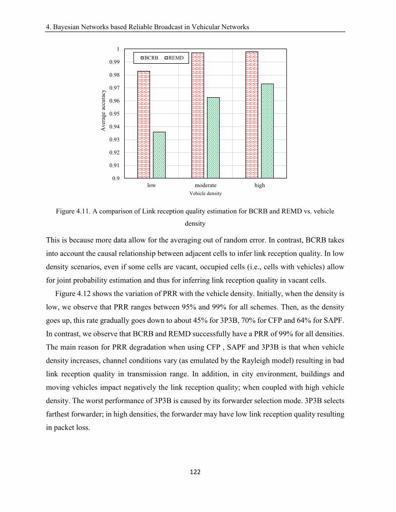
4. Bayesian Networks based Reliable Broadcast in Vehicular Networks
122
Figure 4.11. A comparison of Link reception quality estimation for BCRB and REMD vs. vehicle
density
This is because more data allow for the averaging out of random error. In contrast, BCRB takes
into account the causal relationship between adjacent cells to infer link reception quality. In low
density scenarios, even if some cells are vacant, occupied cells (i.e., cells with vehicles) allow
for joint probability estimation and thus for inferring link reception quality in vacant cells.
Figure 4.12 shows the variation of PRR with the vehicle density. Initially, when the density is
low, we observe that PRR ranges between 95% and 99% for all schemes. Then, as the density
goes up, this rate gradually goes down to about 45% for 3P3B, 70% for CFP and 64% for SAPF.
In contrast, we observe that BCRB and REMD successfully have a PRR of 99% for all densities.
The main reason for PRR degradation when using CFP , SAPF and 3P3B is that when vehicle
density increases, channel conditions vary (as emulated by the Rayleigh model) resulting in bad
link reception quality in transmission range. In addition, in city environment, buildings and
moving vehicles impact negatively the link reception quality; when coupled with high vehicle
density. The worst performance of 3P3B is caused by its forwarder selection mode. 3P3B selects
farthest forwarder; in high densities, the forwarder may have low link reception quality resulting
in packet loss.
0.9
0.91
0.92
0.93
0.94
0.95
0.96
0.97
0.98
0.99
1
low moderate high
Aver
age
accu
racy
Vehicle density
BCRB REMD
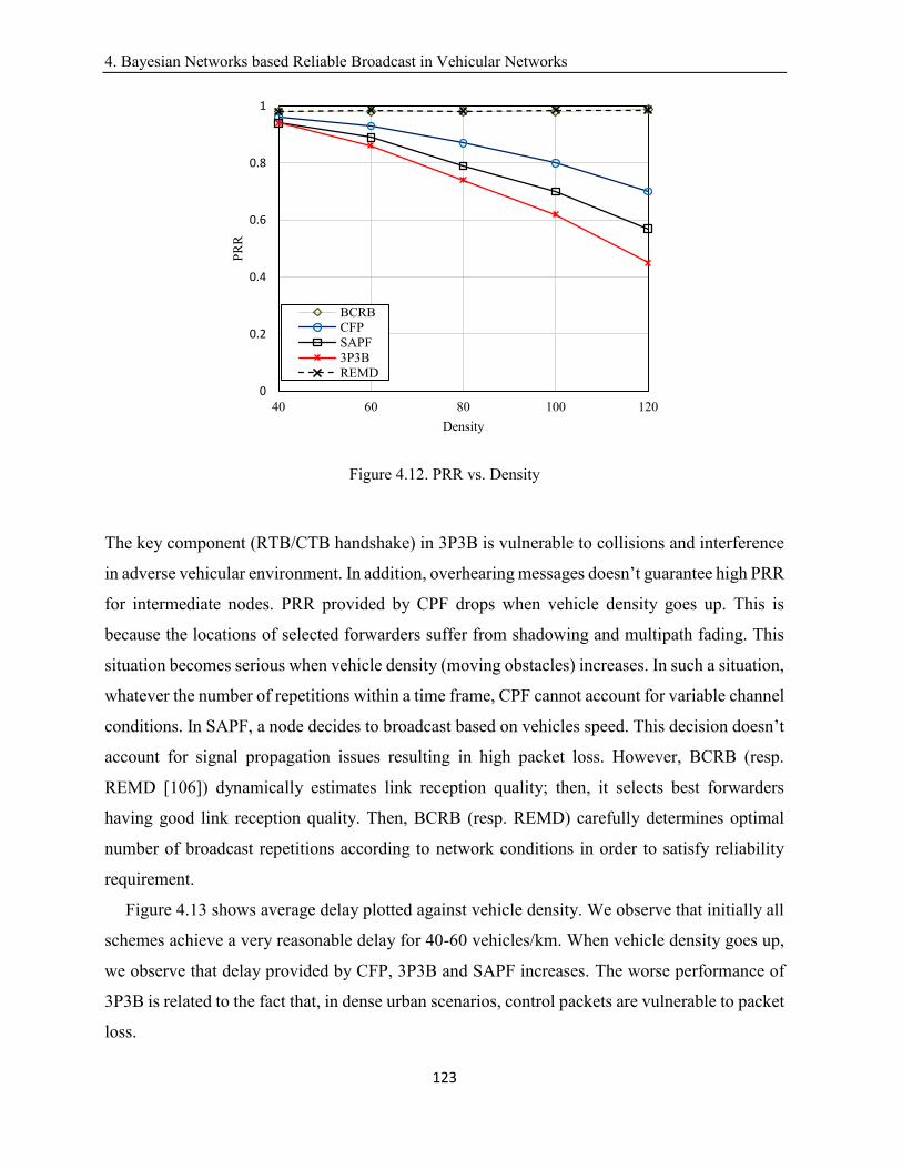
4. Bayesian Networks based Reliable Broadcast in Vehicular Networks
123
Figure 4.12. PRR vs. Density
The key component (RTB/CTB handshake) in 3P3B is vulnerable to collisions and interference
in adverse vehicular environment. In addition, overhearing messages doesn’t guarantee high PRR
for intermediate nodes. PRR provided by CPF drops when vehicle density goes up. This is
because the locations of selected forwarders suffer from shadowing and multipath fading. This
situation becomes serious when vehicle density (moving obstacles) increases. In such a situation,
whatever the number of repetitions within a time frame, CPF cannot account for variable channel
conditions. In SAPF, a node decides to broadcast based on vehicles speed. This decision doesn’t
account for signal propagation issues resulting in high packet loss. However, BCRB (resp.
REMD [106]) dynamically estimates link reception quality; then, it selects best forwarders
having good link reception quality. Then, BCRB (resp. REMD) carefully determines optimal
number of broadcast repetitions according to network conditions in order to satisfy reliability
requirement.
Figure 4.13 shows average delay plotted against vehicle density. We observe that initially all
schemes achieve a very reasonable delay for 40-60 vehicles/km. When vehicle density goes up,
we observe that delay provided by CFP, 3P3B and SAPF increases. The worse performance of
3P3B is related to the fact that, in dense urban scenarios, control packets are vulnerable to packet
loss.
0
0.2
0.4
0.6
0.8
1
40 60 80 100 120
PR
R
Density
BCRB
CFP
SAPF
3P3B
REMD
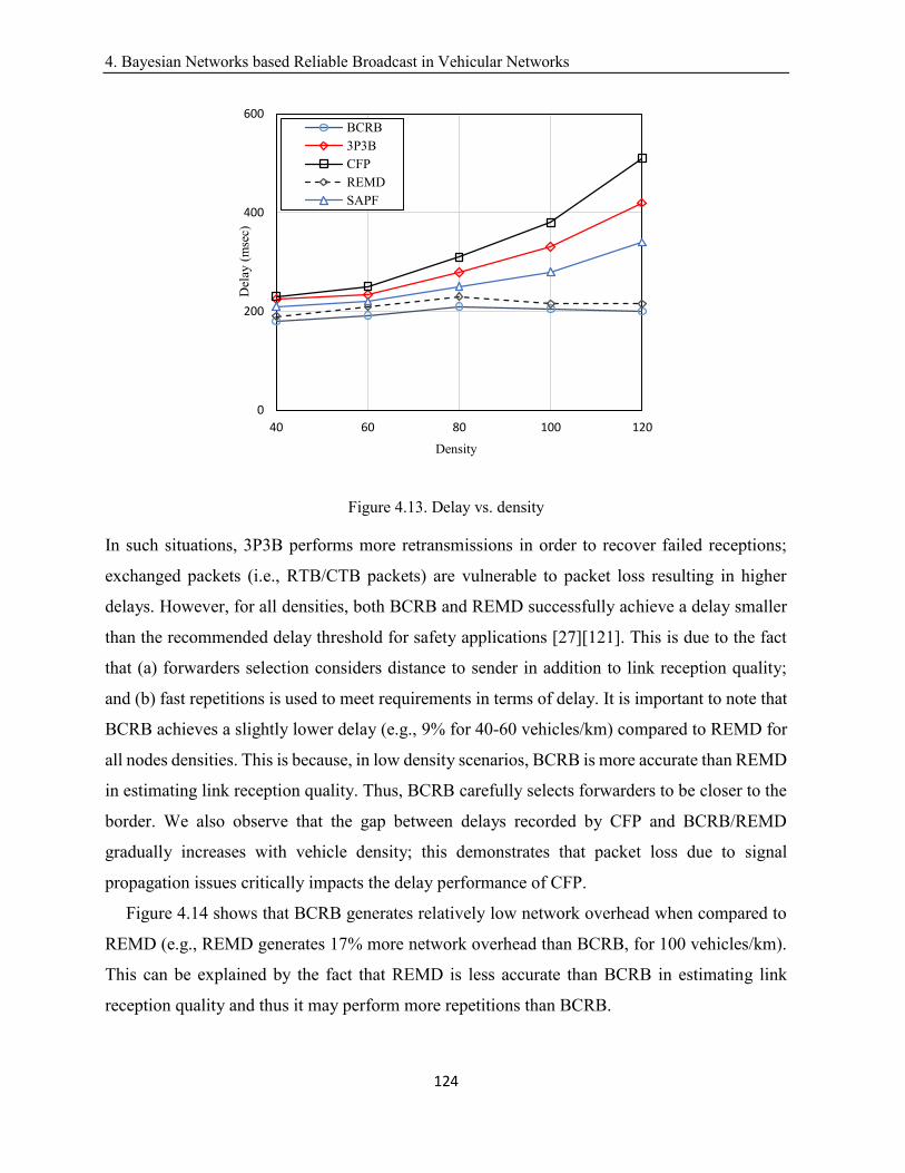
4. Bayesian Networks based Reliable Broadcast in Vehicular Networks
124
Figure 4.13. Delay vs. density
In such situations, 3P3B performs more retransmissions in order to recover failed receptions;
exchanged packets (i.e., RTB/CTB packets) are vulnerable to packet loss resulting in higher
delays. However, for all densities, both BCRB and REMD successfully achieve a delay smaller
than the recommended delay threshold for safety applications [27][121]. This is due to the fact
that (a) forwarders selection considers distance to sender in addition to link reception quality;
and (b) fast repetitions is used to meet requirements in terms of delay. It is important to note that
BCRB achieves a slightly lower delay (e.g., 9% for 40-60 vehicles/km) compared to REMD for
all nodes densities. This is because, in low density scenarios, BCRB is more accurate than REMD
in estimating link reception quality. Thus, BCRB carefully selects forwarders to be closer to the
border. We also observe that the gap between delays recorded by CFP and BCRB/REMD
gradually increases with vehicle density; this demonstrates that packet loss due to signal
propagation issues critically impacts the delay performance of CFP.
Figure 4.14 shows that BCRB generates relatively low network overhead when compared to
REMD (e.g., REMD generates 17% more network overhead than BCRB, for 100 vehicles/km).
This can be explained by the fact that REMD is less accurate than BCRB in estimating link
reception quality and thus it may perform more repetitions than BCRB.
0
200
400
600
40 60 80 100 120
Del
ay (
mse
c)
Density
BCRB
3P3B
CFP
REMD
SAPF
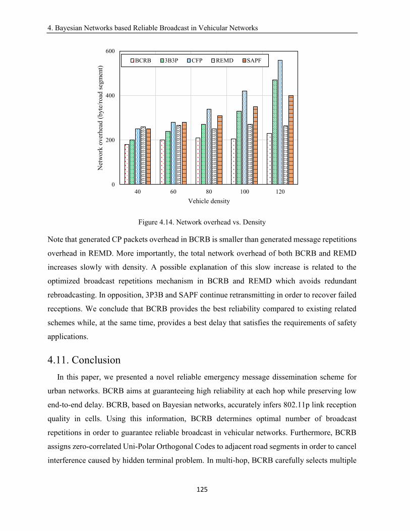
4. Bayesian Networks based Reliable Broadcast in Vehicular Networks
125
Figure 4.14. Network overhead vs. Density
Note that generated CP packets overhead in BCRB is smaller than generated message repetitions
overhead in REMD. More importantly, the total network overhead of both BCRB and REMD
increases slowly with density. A possible explanation of this slow increase is related to the
optimized broadcast repetitions mechanism in BCRB and REMD which avoids redundant
rebroadcasting. In opposition, 3P3B and SAPF continue retransmitting in order to recover failed
receptions. We conclude that BCRB provides the best reliability compared to existing related
schemes while, at the same time, provides a best delay that satisfies the requirements of safety
applications.
4.11. Conclusion
In this paper, we presented a novel reliable emergency message dissemination scheme for
urban networks. BCRB aims at guaranteeing high reliability at each hop while preserving low
end-to-end delay. BCRB, based on Bayesian networks, accurately infers 802.11p link reception
quality in cells. Using this information, BCRB determines optimal number of broadcast
repetitions in order to guarantee reliable broadcast in vehicular networks. Furthermore, BCRB
assigns zero-correlated Uni-Polar Orthogonal Codes to adjacent road segments in order to cancel
interference caused by hidden terminal problem. In multi-hop, BCRB carefully selects multiple
0
200
400
600
40 60 80 100 120
Net
wo
rk o
ver
hea
d (
byte
/ro
ad s
egm
ent)
Vehicle density
BCRB 3B3P CFP REMD SAPF
4. Bayesian Networks based Reliable Broadcast in Vehicular Networks
126
forwarders and their locations. Forwarders of same hop cooperate with the objective to achieve
high reliability in intermediate hops. We validated, via simulation, the proposed graphical model
of 802.11p wireless link reception quality in transmission range. Furthermore, simulation results
show that BCRB achieves better performance compared to existing related schemes. This result
makes it a good emergency message dissemination scheme in urban environments. Future work
will mainly cover the development of new methods for rapid learning algorithms in vehicular
networks.
5. Optimal Gateway Placement and Reliable Internet Access in Urban Vehicular Environments
127
Chapter 5
Optimal Gateway Placement and Reliable
Internet Access in Urban Vehicular
Environments
Abstract
Internet of Vehicles requires reliable Inter-Vehicular communications. Such a requirement is
challenging since the wireless communication channel is very erroneous and lossy in city
environments. A lot of solutions for connecting vehicles to the internet have been proposed.
However, existing multi-hop gateway discovery solutions do not consider, a key issue, the
unreliability of broadcast in city environments. In this paper, our objective is to find out the
minimum communication hops, with very high reliability (e.g., 97%), to gateways. To
accomplish this, we model the gateway placement problem (called GP) as a k-center optimization
problem. We solve it in 𝑂(𝑛2 ∗ 𝑙𝑜𝑔(𝑛)) time using a (2-1) dimension reduction technique. We
make use of M-HRB [31] to discover reliable multi-hop paths to gateways. Simulation results
demonstrate that applying M-HRB with GP provides high packet reception rate and generates
smaller end-to-end delay compared to existing solutions. Furthermore, our proposal makes
efficient use of wireless channel bandwidth.
Key words: Gateway placement, reliability, internet of vehicles, vehicular networks, k-center
optimization problem.
Status: This article is published in IEEE Conference on Local Computer Networks [36];
5.1. Introduction
The main contribution of Intelligent Transportation Systems (ITS) is to significantly increase
road safety. However, ITS is attracting the interest of network operators and service providers for
the provision of infotainment services [6]. In modern cities, people spend a considerable amount
of their time commuting by car from one place to another. To improve the driving experience and
making trips more productive, a plethora of infotainment applications including content
Wiem Benrhaiem, Abdelhakim Hafid, and Pratap Kumar Sahu
5. Optimal Gateway Placement and Reliable Internet Access in Urban Vehicular Environments
128
download, media streaming, VoIP, social networking, gaming, cloud access, etc., have been made
available to vehicular users anytime and anywhere. This calls for vehicular communication
networks to support Internet services in vehicles [10]. Indeed, In-vehicle Internet access [10]
allows a vehicle to connect to the Internet through an Internet gateway. Traditionally, an internet
gateway is an RSU, installed in fixed position along a roadside. A main benefit of such an
infrastructure is to relieve poor network connectivity (e.g., RSUs can increase the overall coverage
of a vehicular network and enhance network performance (i.e., delay) between disconnected
vehicles) [11]. Unfortunately, Internet access through RSUs requires pervasive RSUs to ensure
each vehicle is in RSU’s transmission range [11] (i.e., the typical range of an RSU is 250m). Such
a requirement incurs high infrastructure deployment cost. Several contributions
[12][13][14][15][16] are proposed to optimally place RSUs. Indeed, deploying a new RSU needs
intensive investigation [11]; for instance, the land where to place a new RSU may be private
requiring owner permission. It may be difficult, if not impossible, to get such a permission.
Therefore, deploying new RSUs often requires a large amount of investment and elaborate design,
especially at the city scale. Consequently, internet access systems that rely only on roadside
infrastructure are impracticable to be implemented. Recently, the concept of LTE-connected
vehicles [17] (i.e., a vehicle equipped with 802.11p and UTRAN interfaces) has received a lot of
attention. Once in the range of a LTE base station, the vehicle gets internet access. Actually, LTE
provides a robust mechanism for mobility management of vehicles [18] (i.e., supports a data rate
of 10 Mbps with a speed up to 140 km per hour). LTE also fits the bandwidth demands and the
quality of service requirements of infotainment applications [18]. However, mobile data is
experiencing explosive growth [19]; this makes LTE cellular infrastructure bandwidth not able to
keep up with connecting high number of connected vehicles [20]. Also, it has been reported that
cellular infrastructure connectivity cannot evolve once it is installed [17]. Furthermore, many
vehicles incur frequent handoffs, because of high mobility, requiring higher bandwidth [21].
Hence, allowing only some connected vehicles to operate as gateways (mobile gateways) to other
vehicles may be effective [22]. Several contributions [23] [24] [25] [26] have focused on
proposing various Internet access systems using connected vehicles as gateways. Getting internet
access through either RSUs ([12] [13] [14]) or connected vehicles ([23] [24] [25] [26]) relies on
multi-hop communication links. Typically, a vehicle connects to a gateway in its vicinity. In case
no internet gateway in the range, a vehicle relies on multi-hop communications to connect to a
5. Optimal Gateway Placement and Reliable Internet Access in Urban Vehicular Environments
129
gateway beyond its transmission range. A gateway discovery protocol is required to discover
routes (i.e., an established route is a fixed succession of nodes between the source and the
destination) to gateways not in the range. Random loss in wireless ad hoc networks is caused by
lossy wireless communication channels and node mobility. Typically, transmission in wireless
medium is always vulnerable to packet collisions and interferences due to various wave
propagation issues such as signal attenuation, noise and jitter. These effects are quite predominant
in vehicular networks in the presence of high rise buildings making vehicular networks quite
unreliable. Achieving very high reliability in the presence of all kinds of wireless network
vulnerabilities is a major challenge in vehicular networks. Gateway discovery protocols use IEEE
802.11p broadcast communication mode. However, IEEE 802.11p broadcast does not support
acknowledgement. Therefore, losses of messages due to packet collisions, poor channel
conditions, etc., cannot be easily detected. Gateway discovery protocols should be able to establish
reliable paths in the presence of all such conditions. In this paper, we introduce a reliable multi-
hop internet access system (called RICS) for urban vehicular environments. Basically, we make
use of both LTE-connected vehicles and the already deployed RSUs infrastructure as gateways.
RSUs have a considerable impact on network reliability, as they are fixed reliable nodes [55].
Because of random mobility of vehicles, there is the possibility of network fragmentation. Static
RSUs may act as bridges between fragmented groups of vehicles [11]. LTE-connected vehicles
enhance gateways availability because adding such vehicles (e.g., buses and taxis) doesn’t require
additional infrastructure (e.g., land). In [22], it has been reported that using connected vehicles as
gateways increases the probability, for moving vehicles, to set up paths with fewer hops. To ensure
reliable multi-hop In-vehicle Internet access, our objective is to find out the minimum possible
communication hops, from a requesting vehicle to a fixed/mobile gateway, with high reliable
message dissemination (e.g., 97%). To accomplish this, we model the gateways placement
problem (called GP) as a 2-dimentional k-center [56] optimization problem. This problem is
known to be NP-hard. We make a dimension reduction of the optimization problem and propose
an exact time resolution algorithm to solve it. On top of the minimum communication hops, we
implement a gateway discovery protocol M-HRB [31] which exploits the reception quality of
802.11p wireless links to establish high reliable communication paths. The remainder of this paper
is organized as follows. Section 5.2 presents related work. Section 5.3 presents our assumptions
and the basic idea of the proposed scheme. Section 5.4 presents the gateway placement
5. Optimal Gateway Placement and Reliable Internet Access in Urban Vehicular Environments
130
optimization problem. Section 5.5 presents the gateway discovery protocol. Section 5.6 described
the proposed solution. Finally, Section 5.7 concludes the paper.
5.2. Related Work
Several gateway discovery schemes (i.e., [50][26][51][52]) have been proposed in the
literature. These schemes can be classified into three categories: (1) Proactive approaches
[50][52], where gateways advertise themselves in the whole network. In [50], the gateway with
the maximum route connection’s duration is selected (The route connection’s duration represents
the time elapsed before a connection breaks along the route, which is estimated using traffic
density and distance to gateway). In [52], gateways employ the concept of connected dominating
set (CDS) to retransmit the advertisement message. Every vehicle is either in CDS or adjacent to
at least one node in CDS. The CDS nodes are selected using route lifetime parameter. The route
lifetime is the minimum of the lifetimes of its constituent links; link lifetime is the time difference
between link initiation and link breakage/termination; (2) Reactive approaches [26][51][53],
where vehicles (called requesters), that want internet access, need to flood the network for
gateway discovery. In [26], the discovery protocol uses location and speed of vehicles to predict
when the route to the gateway will break and preemptively creates new routes to replace old ones
before they break. In [51], the discovery protocol selects few forwarding nodes to reduce
overhead of the protocol in [26]. Speed of neighboring vehicles is a main parameter to predict
lifetime of links between two vehicles. The gateway with the maximum predicted route lifetime
to the source is selected. In [53], the route that can stay longer (i.e., has biggest lifetime), between
the vehicle and the gateway, is selected. The discovery process makes use of predictable vehicle
mobility, which is limited by traffic pattern and road layout. We conclude that reactive schemes
suffer from poor scalability in discovering gateways as all vehicles send requests; and (3) Hybrid
approaches [75][54], where gateways advertise themselves to their neighbors (1 or n hops away);
then, requesters send packets to find a gateway in these advertisement areas. The selection of
advertisement zones depends on the dimension of the network. A small advertisement zone could
result in high reactive overhead, and a large advertisement zone could result in high proactive
overhead. In [54], the authors use the characteristics of vehicle movements (e.g., speed and
direction of movement) to predict the future behavior of vehicles, and to select a route with the
longest lifetime to connect to the wired network. In [75], the position of the destination and the
5. Optimal Gateway Placement and Reliable Internet Access in Urban Vehicular Environments
131
position of neighboring nodes are used to forward data without establishing routes in the
advertisement area. Any node that ensures progress toward the destination can be used for
forwarding. The forwarding decision is based on the position of destination vehicle and position
of one hop neighbors. However, the link to the selected node may be unreliable in harsh network
conditions leading to packet loss. From above discussions, we can conclude that the route
discovery schemes do not guarantee reliable communication, in city settings. Existing schemes
(e.g., [26][51][53][54]) make use of link stability metric, which is based only on mobility metrics
(e.g., relative motion between neighboring vehicles, speed, etc.), to determine paths to gateways.
In city settings, such a selected route can be broken frequently owing to the high mobility of
vehicles. In [22], it has been proved that the number of breakages of a path increases with the
number of hops in the path. Thus, the node centric view of the routes in [26][51][52][54][53]
leads to frequent broken routes in the presence of VANETs’ random loss (high mobility and lossy
wireless communication channel). Consequently, many packets can be dropped, and the
overhead due to route repairs or failure notifications significantly increases, leading to low
delivery ratios and high transmission delays of advertisement messages. Thus, vehicles that are
far away from the mobile gateway transmission range will have limited or very poor internet
connectivity.
5.3. Proposed Scheme
5.3.1. Assumptions
In this chapter, we consider a scenario where vehicles are moving on urban streets. We choose
a city map where the length of a road segment is random. We assume that (1) vehicles are equipped
with a Global Positioning System (GPS) and digital road maps; (2) RSUs (equipped with 802.11p
interface and wired access to the backbone internet) are distributed randomly with a predefined
density; (3) all vehicles are equipped with IEEE 802.11p [18] wireless technology and
computation capabilities; (4) LTE-connected vehicles (equipped with both IEEE 802.11p and
LTE interfaces) are distributed randomly with a predefined density; (5) connected vehicles are in
the range of an LTE base station; (6) obstacles (e.g., buildings) exist; thus, this may impact
communication among vehicles; and (7) vehicles density information is transmitted according to
the scheme in [122] to a central server, for each time period 𝑇𝑔 (e.g., 𝑇𝑔=1 minute).
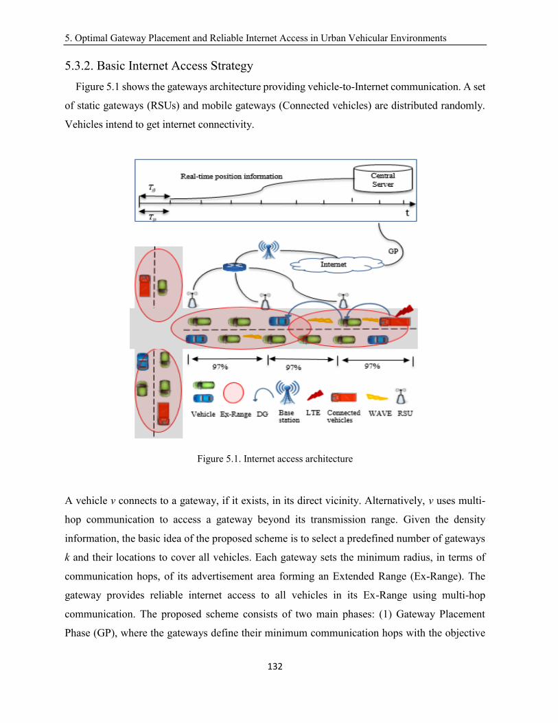
5. Optimal Gateway Placement and Reliable Internet Access in Urban Vehicular Environments
132
5.3.2. Basic Internet Access Strategy
Figure 5.1 shows the gateways architecture providing vehicle-to-Internet communication. A set
of static gateways (RSUs) and mobile gateways (Connected vehicles) are distributed randomly.
Vehicles intend to get internet connectivity.
Figure 5.1. Internet access architecture
A vehicle v connects to a gateway, if it exists, in its direct vicinity. Alternatively, v uses multi-
hop communication to access a gateway beyond its transmission range. Given the density
information, the basic idea of the proposed scheme is to select a predefined number of gateways
k and their locations to cover all vehicles. Each gateway sets the minimum radius, in terms of
communication hops, of its advertisement area forming an Extended Range (Ex-Range). The
gateway provides reliable internet access to all vehicles in its Ex-Range using multi-hop
communication. The proposed scheme consists of two main phases: (1) Gateway Placement
Phase (GP), where the gateways define their minimum communication hops with the objective
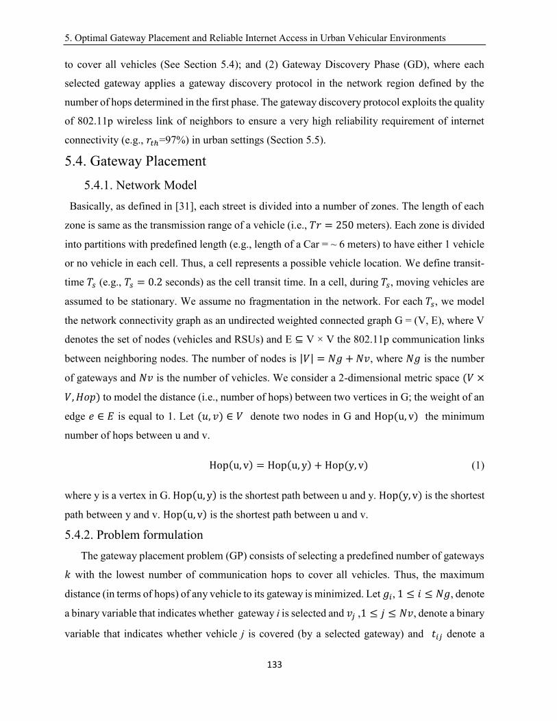
5. Optimal Gateway Placement and Reliable Internet Access in Urban Vehicular Environments
133
to cover all vehicles (See Section 5.4); and (2) Gateway Discovery Phase (GD), where each
selected gateway applies a gateway discovery protocol in the network region defined by the
number of hops determined in the first phase. The gateway discovery protocol exploits the quality
of 802.11p wireless link of neighbors to ensure a very high reliability requirement of internet
connectivity (e.g., 𝑟𝑡ℎ=97%) in urban settings (Section 5.5).
5.4. Gateway Placement
5.4.1. Network Model
Basically, as defined in [31], each street is divided into a number of zones. The length of each
zone is same as the transmission range of a vehicle (i.e., 𝑇𝑟 = 250 meters). Each zone is divided
into partitions with predefined length (e.g., length of a Car = ~ 6 meters) to have either 1 vehicle
or no vehicle in each cell. Thus, a cell represents a possible vehicle location. We define transit-
time 𝑇𝑠 (e.g., 𝑇𝑠 = 0.2 seconds) as the cell transit time. In a cell, during𝑇𝑠, moving vehicles are
assumed to be stationary. We assume no fragmentation in the network. For each𝑇𝑠, we model
the network connectivity graph as an undirected weighted connected graph G = (V, E), where V
denotes the set of nodes (vehicles and RSUs) and E ⊆ V × V the 802.11p communication links
between neighboring nodes. The number of nodes is |𝑉| = 𝑁𝑔 + 𝑁𝑣, where 𝑁𝑔 is the number
of gateways and 𝑁𝑣 is the number of vehicles. We consider a 2-dimensional metric space (𝑉 ×
𝑉,𝐻𝑜𝑝) to model the distance (i.e., number of hops) between two vertices in G; the weight of an
edge 𝑒 ∈ 𝐸 is equal to 1. Let (𝑢, 𝑣) ∈ 𝑉 denote two nodes in G and Hop(u, v) the minimum
number of hops between u and v.
Hop(u, v) = Hop(u, y) + Hop(y, v) (1)
where y is a vertex in G.Hop(u, y) is the shortest path between u and y. Hop(y, v) is the shortest
path between y and v. Hop(u, v) is the shortest path between u and v.
5.4.2. Problem formulation
The gateway placement problem (GP) consists of selecting a predefined number of gateways
𝑘 with the lowest number of communication hops to cover all vehicles. Thus, the maximum
distance (in terms of hops) of any vehicle to its gateway is minimized. Let 𝑔𝑖, 1 ≤ 𝑖 ≤ 𝑁𝑔, denote
a binary variable that indicates whether gateway i is selected and 𝑣𝑗 ,1 ≤ 𝑗 ≤ 𝑁𝑣, denote a binary
variable that indicates whether vehicle j is covered (by a selected gateway) and 𝑡𝑖𝑗 denote a
5. Optimal Gateway Placement and Reliable Internet Access in Urban Vehicular Environments
134
binary variable that indicates whether vehicle 𝑣𝑗 is covered by gateway𝑔𝑖. The integer linear
programming (ILP) [123] of the GP problem can be expressed as follows:
Min1≤i≤Ng (Max1≤j≤Nv(Hop(gi, vj) ∗ tij)) (2)
S.c.t
∑ gii=Ngi=1 ≤ k (3)
gi ≥ tij∀i, ∀j (4)
∑ tij ≥ 1i ∀j (5)
gi, vj, tij ∈ {0,1}∀i, ∀j (6)
The objective function (2) determines the minimum number of hops that enables every vertex
(vehicle) to be connected to one of the k Internet gateways. Constraint (3) ensures that the number
of gateways is not greater than k. Constraint (4) guarantees that a gateway is placed before being
used. Constraint (5) guarantees that each non-gateway vehicle can reach at least one of the
gateways. Constraint (6) is the integrity constraint of the decision variables. In contrast to cellular
networks, in vehicular networks, the availability of a gateway changes frequently due to high
mobility. Hence, a vehicular gateway enables short connection duration when compared to the
connection duration to a cellular base station [50][124][125]. In our model, the GP problem is
resolved each update time 𝑇𝑝. The update time 𝑇𝑝 represents the average road segment transit
time (e.g., Tp = 62s ≈ 1 minute, average length of road segment is 500 m and average vehicles
speed is 30 kilometer/hour). The central server (Figure 5.1) provides real-time density
information each 1 minute [126]. Therefore, Tp ≈ Tg.
Proposition: GP is NP-hard.
Proof: To prove this, we use a reduction from the Euclidian k-center [127] problem (a
variant of the Facility Location Problem (FLP) [127]). Given a two dimensional metric space
with a set S of n points in the plan and a positive integer k, the k-center problem is to find k
congruent disks of minimum radius r that cover S. The Euclidian distance between two points in
S is denoted by d. In the k-center problem, the radius r of a disk represents the maximum distance
d from a point, in S, to its closest disk center. The Euclidian distance d between any two points
in S satisfies the triangle inequality [18]. The k-center aims to minimize r. In the GP problem,
the k Internet gateways are referred to as the centers of the network connectivity graph G. As for
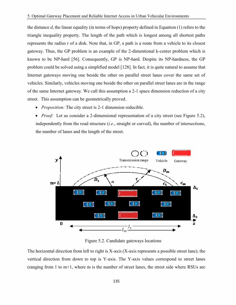
5. Optimal Gateway Placement and Reliable Internet Access in Urban Vehicular Environments
135
the distance d, the linear equality (in terms of hops) property defined in Equation (1) refers to the
triangle inequality property. The length of the path which is longest among all shortest paths
represents the radius r of a disk. Note that, in GP, a path is a route from a vehicle to its closest
gateway. Thus, the GP problem is an example of the 2-dimentional k-center problem which is
known to be NP-hard [56]. Consequently, GP is NP-hard. Despite its NP-hardness, the GP
problem could be solved using a simplified model [128]. In fact, it is quite natural to assume that
Internet gateways moving one beside the other on parallel street lanes cover the same set of
vehicles. Similarly, vehicles moving one beside the other on parallel street lanes are in the range
of the same Internet gateway. We call this assumption a 2-1 space dimension reduction of a city
street. This assumption can be geometrically proved.
Proposition: The city street is 2-1 dimension reducible.
Proof: Let us consider a 2-dimensional representation of a city street (see Figure 5.2),
independently from the road structure (i.e., straight or curved), the number of intersections,
the number of lanes and the length of the street.
Figure 5.2. Candidate gateways locations
The horizontal direction from left to right is X-axis (X-axis represents a possible street lane); the
vertical direction from down to top is Y-axis. The Y-axis values correspond to street lanes
(ranging from 1 to m+1, where m is the number of street lanes, the street side where RSUs are
5. Optimal Gateway Placement and Reliable Internet Access in Urban Vehicular Environments
136
placed is considered as a virtual street lane with no vehicles. Thus, the maximum value in Y-axis
is m+1). An X-axis value is proportional to the cell length [31]. X-axis values are proportional
to cell length (6 meters). Given two gateways locations 𝑜1 and 𝑜2 at the same X-axis value, let
disk 𝐷1(𝑜1, 𝑟) and disk 𝐷2(𝑜2, 𝑟) represent the wireless coverage of gateways 𝑜1 and 𝑜2
respectively. r is the disk radius. In figure 2, we suppose r=1. Let ∆1 and ∆2 represent the street
border lanes. The equation of any straight line, called a linear equation, can be written as: “y =
ax + b”, where a is the slope of the line and b is the y-intercept. Thus,∆1 corresponds to y=m ,
where m is the number of street lanes, and ∆2 corresponds to 𝑦=0. Let 𝑐1 and 𝑐𝑚 be the X-axis
coordinates of the rightmost intersection points of the street border lane ∆1 , with 𝐷1 and𝐷2,
respectively. The value of |𝑐1 − 𝑐𝑚| is negligible when compared to a vehicle location (6 meters
[31]).
|cm − c1| ≪ 6 (7)
Therefore, gateways that have the same X-axis values cover the same set of vehicles. Similarly,
vehicles that have the same X-axis value are covered by the same gateway. We denote by 𝑝𝑖 ,
(1 ≤ 𝑖 ≤ ⌈𝑛
𝑚+1⌉) , n is the total number of nodes on the street and m is the number of street lanes,
the orthogonal projection of the nodes (vehicles and RSUs) onto the X-axis. Thus, 𝑝𝑖 represents
a virtual representation of all street nodes on the same straight line; this line models the street.
5.4.3. One-dimensional GP
In this section, we make use of a 2-1 dimension reduction [130] of GP. We convert the GP
problem from a (V × V, Hop) dimensional space to a(𝑉, Hop) dimensional space. Given the one-
dimensional representation of the city street, we define the one-dimensional GP problem on a
line as follows: Given a set S of n points (i.e., vehicles) lying on a line and an integer k ≥ 1, find
k intervals with centers (i.e., gateways) on that line such that the union of the intervals covers S
and the maximum radius of the interval (half of its length) is minimized. The basic idea of the 2-
1 dimensional reduction algorithm is to represent the nodes (i.e., vehicles and RSUs) along the
street by points 𝑝𝑖 obtained by orthogonal projection of the street nodes onto the X-axis. The
orthogonal projection of the nodes (vehicles and RSUs) on the X-axis results in three categories
of points: (1) a gateway point; (2) a vehicle point; and (3) a combined gateway-vehicle point.
The 2-1 dimensional reduction algorithm is detailed in Algorithm I. The major steps of Algorithm
I are as follows. First, nodes are grouped according to their X-axis coordinate; nodes that have
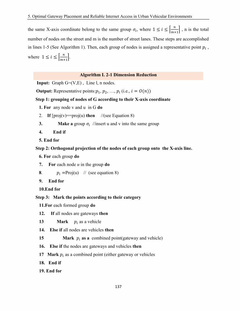
5. Optimal Gateway Placement and Reliable Internet Access in Urban Vehicular Environments
137
the same X-axis coordinate belong to the same group 𝜎𝑖, where 1 ≤ 𝑖 ≤ ⌈𝑛
𝑚+1⌉ , n is the total
number of nodes on the street and m is the number of street lanes. These steps are accomplished
in lines 1-5 (See Algorithm 1). Then, each group of nodes is assigned a representative point 𝑝𝑖 ,
where 1 ≤ 𝑖 ≤ ⌈𝑛
𝑚+1⌉.
Algorithm I. 2-1 Dimension Reduction
Input: Graph G=(V,E) , Line l, n nodes.
Output: Representative points:𝑝1, 𝑝2, …, 𝑝𝑖(i.e., 𝑖 = 𝑂(𝑛))
Step 1: grouping of nodes of G according to their X-axis coordinate
1. For any node v and u in G do
2. If [proj(v)==proj(u) then //(see Equation 8)
3. Make a group 𝜎𝑖 //insert u and v into the same group
4. End if
5. End for
Step 2: Orthogonal projection of the nodes of each group onto the X-axis line.
6. For each group do
7. For each node u in the group do
8. 𝑝𝑖 =Proj(u) // (see equation 8)
9. End for
10.End for
Step 3: Mark the points according to their category
11.For each formed group do
12. If all nodes are gateways then
13 Mark 𝑝𝑖 as a vehicle
14. Else if all nodes are vehicles then
15 Mark 𝑝𝑖 as a combined point(gateway and vehicle)
16. Else if the nodes are gateways and vehicles then
17 Mark 𝑝𝑖 as a combined point (either gateway or vehicles
18. End if
19. End for

5. Optimal Gateway Placement and Reliable Internet Access in Urban Vehicular Environments
138
20. Return the set of 𝒑𝒊 points
The point 𝑝𝑖 is obtained using an orthogonal projection, on the X-axis, of any node of the group.
If 𝑒 = (1,0) the unit vector in the direction of the X-axis and 𝑣𝑖 = (a,b) a node that belongs to
group 𝜎𝑖 , then the orthogonal projection 𝑝𝑖 of 𝑣𝑖 = (a,b) onto the X-axis is as follows:
pi = proj(vi) = (a, 0) (8)
Then, we make use of three markups to obtain three categories of points. If all nodes in the
group are vehicles, then the representative point is marked as a vehicle. If the nodes in the group
are all gateways, then the point is marked as a gateway. If the group consists of gateways and
vehicles, then the point is marked as a combined point. These steps are accomplished in lines 6-
19 (See Algorithm I). Finally, we return the set of points in line 20.
5.4.4. Exact solution
In this section, we present the decision algorithm to solve the 1-dimensional GP problem. The
resolution process is described in Algorithm II. The basic idea of the algorithm is to increase the
radius r until covering all points (vehicles) using k intervals. Indeed, if we increase radius r, then
the required number of gateways k will decrease. We start by an optimal radius which is equal
to 1 hop (the transmission range). Then, we increase the radius r each time by 1 hop. The
algorithm ends if it meets the required number of gateways k and returns radius r. The major
steps of Algorithm II are as follows: (1) we initiate the radius of gateways to 1 in line 1. Then,
we generate the coverage intervals Ii(r) (the interval center is a gateway representing point 𝑝𝑖;
the length of the interval equals 2 ∗ 𝑟) of all points marked as gateways or combined points, in
lines 2-7; (2) we sort the intervals according to their left endpoints ai(r); this is accomplished in
line 8; (3) we select the gateways as follows: In line 12, we select the leftmost endpoint in the
sorted intervals set.

5. Optimal Gateway Placement and Reliable Internet Access in Urban Vehicular Environments
139
Algorithm II. Gateway Placement
Input: Set of 𝒑𝒊 points (Output of Algorithm I)
Required number of gateways k.
Output: Radius r (minimum communication hops).
A set of selected gateways locations.
1. Initiate radius r=1
2. For each gateway 𝑝𝑖 do
3. ai(r) = 𝑝𝑖 − (𝑟, 0) (See Equation 8)
4. bi(r) = 𝑝𝑖 + (𝑟, 0) (See Equation 8)
5. Ii(r) = [ai(r), bi(r)]
6. End for
7. I = {Ii(r)}
8. Sort intervals in 𝐼 according to the X-axis coordinate of the left endpoint 𝑎𝑖.
9. 𝑘(𝑟) = 0
10. While[(𝑘(𝑟) ≤ 𝑘) and (not all vehicles are covered)] do
11. While (𝑰 ≠ ∅)
12. Select the leftmost endpoint ai(r) in the sorted I
13. Mark its center 𝑝𝑖 as a selected gateway point
14. 𝑘(𝑟) + +
15. Binary Search of any interval Ii(r)in 𝐼 that covers
the selected gateway point 𝑝𝑖
16. I=I\ {Ii(r)}
17. End while
18. End while
19. If [(𝒌(𝒓) ≤ 𝒌)] and (all vehicles are covered) then
20. Return radius r and the selected gateways
21. Else
22. r ++
23. Go to step 2
24. End if
5. Optimal Gateway Placement and Reliable Internet Access in Urban Vehicular Environments
140
We mark its center as a selected gateway, in line 13. We increase the number of selected
gateways k, in line 14; (4) in lines 15-16, we perform a binary search in the set of intervals I to
find all intervals that cover the selected gateway center. If any, we remove that interval from
intervals set I. These steps are briefly listed in line 15; and (5) in lines 19-24, we check whether
the number of selected gateways k(r) is smaller than the predefined number of gateways k and
all vehicle points are covered. If the response is no, we increase the radius r and repeat steps of
lines 2-18; otherwise, we identify the gateways placement set and the minimum radius in line 20.
Proposition: Algorithm II selects k(r) gateways and minimizes the length r of the path
which is longest among all shortest paths in 𝑂(𝑛2 ∗ log(𝑛)), where n is the total number of nodes
along the street. Note that, a path is a route from a vehicle to its closest gateway.
Proof: The number of gateways k is bounded by n. For each radius r, we sort the intervals,
in line 8, which takes𝑂(𝑛log(𝑛)). Then, in line 10, we iteratively select at most 𝑘 = 𝑛
gateways. Therefore, the complexity of this step is 𝑂(𝑛). For each selected gateway, we do binary
search in line 15. The complexity of the binary search is 𝑂(𝑛 log(𝑛)). The complexity of lines
10-18 is 𝑂(𝑛2 ∗ log(𝑛)). Therefore, the total running time of the decision algorithm is𝑂(𝑛2 ∗
log(𝑛)).
Proposition: Algorithm II returns optimal radius ( called 𝑟∗). Note that optimal radius
means the minimum radius such that there exist k gateways of that radius with union covering n
input points.
Proof: To prove this, we suppose the proposition was false, i.e., let us assume that there
exists an optimal radius 𝑟𝑜𝑝𝑡 , such that 𝑟𝑜𝑝𝑡 < 𝑟∗ and that there exist k gateways of that radius
with union covering n input points. Let 𝑆 be the set of input points. Let dmax be the maximum
distance in terms of hops from a vehicle to its closest gateway; 𝑑𝑚𝑎𝑥 = 𝑚𝑎𝑥 ⌈|𝑥𝑖−𝑥𝑗|
𝑇𝑟⌉, where 𝑥𝑖
is the X-axis value of a vehicle point and 𝑥𝑗 is the X-axis value of a gateway point, 1 ≤ 𝑖 ≤ 𝑛,
1 ≤ 𝑗 ≤ 𝑛. It is clear that 𝑟𝑜𝑝𝑡 ≥ 𝑑𝑚𝑎𝑥. Algorithm II increases the radius r each iteration by 1
hop. If the following conditions: 1) number of selected gateways 𝑘(𝑟) is upper bounded by k;
and 2) all points in S are covered; are true, the algorithm returns 𝑟∗. Therefore, in case the number
of selected gateways when 𝑟 = 𝑑𝑚𝑎𝑥 is not greater than k, and all points in S are covered, then
r∗ = 𝑑𝑚𝑎𝑥. However, we have already supposed that 𝑟𝑜𝑝𝑡 < 𝑟∗. As a result, 𝑟𝑜𝑝𝑡 < 𝑑𝑚𝑎𝑥 which
5. Optimal Gateway Placement and Reliable Internet Access in Urban Vehicular Environments
141
is not possible. This contradiction shows that 𝑟𝑜𝑝𝑡 = 𝑟∗. Now, in what follows we suppose 𝑟𝑜𝑝𝑡 >
𝑑𝑚𝑎𝑥 and 𝑟 > 𝑑𝑚𝑎𝑥. As r increases, the endpoint ai(r)of an interval Ii(r)decreases (the endpoint
point bi(r) increases) and the number of gateway points in the interval Ii(r) increases. Thus, k(r)
decreases only when the relative order of the endpoints 𝑎𝑖(𝑟) (or b𝑖(𝑟)) and the gateway points
𝑝𝑖 changes. When r increases, the binary search in line 15 of Algorithm II removes more gateway
points from the interval of the selected gateway point. Consequently, the number of remained
intervals in line 16 decreases and the number of selected gateways k(r) computed in line 14
decreases. Our goal is to find the minimum radius 𝑟∗ such that 𝑘(𝑟∗)is the largest integer with
𝑘(𝑟∗) ≤ 𝑘 and covering all points in S. Since k(r) can decrease only when the radius increases,
a straightforward way to find the radius 𝑟∗ is to keep increasing radius r by 1 hop (line 22). For
each iteration, we do a binary search (line15) and we remove intervals containing the selected
gateway. In line 19, we evaluate if 𝑘(𝑟) ≤ 𝑘 and if all points in S are covered. If the condition is
false, we increase r until the first time the condition is true. Finally, we return 𝑟∗ in line 20. As
we supposed, above, that 𝑟𝑜𝑝𝑡 < 𝑟∗. This means, ∋ 𝑟, such that 𝑟 < 𝑟∗and 𝑘(𝑟) ≤ 𝑘 covering all
input points. This is not possible because Algorithm II returns 𝑟∗ the first time the two conditions
are true). This contradiction concludes the proof and shows, as before, that 𝑟∗ = 𝑟𝑜𝑝𝑡. Therefore,
Algorithm II returns optimal radius.
5.5. Gateway Discovery
In this section, we present the gateway discovery protocol. Each gateway periodically
broadcasts advertisement messages to all vehicles located in its Ex-Range. In [31], we already
proved the effectiveness of M-HRB protocol to ensure very high reliability for multi-hop
emergency message dissemination in city environments. For this reason we make use of M-HRB
to establish reliable paths between gateways and vehicles. As the vehicle can move in any
direction to travel, this creates a rapid changing topology at any speed resulting in difficulties to
handle the vehicular node mobility. Thus, M-HRB makes use of the vehicle location to select the
forwarding node. The main idea of M-HRB is to ensure very high reliability for each hop. To
achieve this, M-HRB estimates the reception quality of 802.11p wireless link in cells to select
forwarding nodes locations [31]. Basically, M-HRB exploits periodic beacons to estimate the
quality of 802.11p wireless link. Using this information, each hop, minimum possible forwarding
locations are selected to enforce achieving very high reliability.
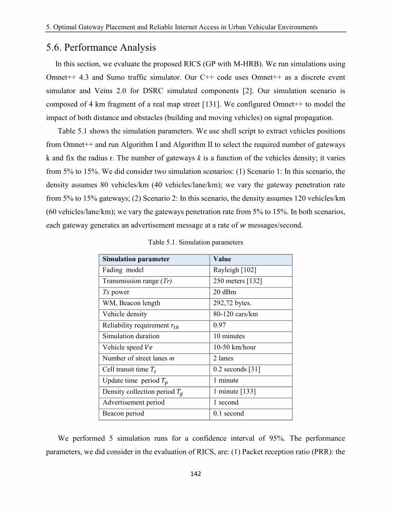
5. Optimal Gateway Placement and Reliable Internet Access in Urban Vehicular Environments
142
5.6. Performance Analysis
In this section, we evaluate the proposed RICS (GP with M-HRB). We run simulations using
Omnet++ 4.3 and Sumo traffic simulator. Our C++ code uses Omnet++ as a discrete event
simulator and Veins 2.0 for DSRC simulated components [2]. Our simulation scenario is
composed of 4 km fragment of a real map street [131]. We configured Omnet++ to model the
impact of both distance and obstacles (building and moving vehicles) on signal propagation.
Table 5.1 shows the simulation parameters. We use shell script to extract vehicles positions
from Omnet++ and run Algorithm I and Algorithm II to select the required number of gateways
k and fix the radius r. The number of gateways k is a function of the vehicles density; it varies
from 5% to 15%. We did consider two simulation scenarios: (1) Scenario 1: In this scenario, the
density assumes 80 vehicles/km (40 vehicles/lane/km); we vary the gateway penetration rate
from 5% to 15% gateways; (2) Scenario 2: In this scenario, the density assumes 120 vehicles/km
(60 vehicles/lane/km); we vary the gateways penetration rate from 5% to 15%. In both scenarios,
each gateway generates an advertisement message at a rate of 𝑤 messages/second.
Table 5.1. Simulation parameters
Simulation parameter Value
Fading model Rayleigh [102]
Transmission range (Tr) 250 meters [132]
Tx power 20 dBm
WM, Beacon length 292,72 bytes.
Vehicle density 80-120 cars/km
Reliability requirement 𝑟𝑡ℎ 0.97
Simulation duration 10 minutes
Vehicle speed 𝑉𝑒 10-50 km/hour
Number of street lanes m 2 lanes
Cell transit time 𝑇𝑠 0.2 seconds [31]
Update time period 𝑇𝑝 1 minute
Density collection period 𝑇𝑔 1 minute [133]
Advertisement period 1 second
Beacon period 0.1 second
We performed 5 simulation runs for a confidence interval of 95%. The performance
parameters, we did consider in the evaluation of RICS, are: (1) Packet reception ratio (PRR): the
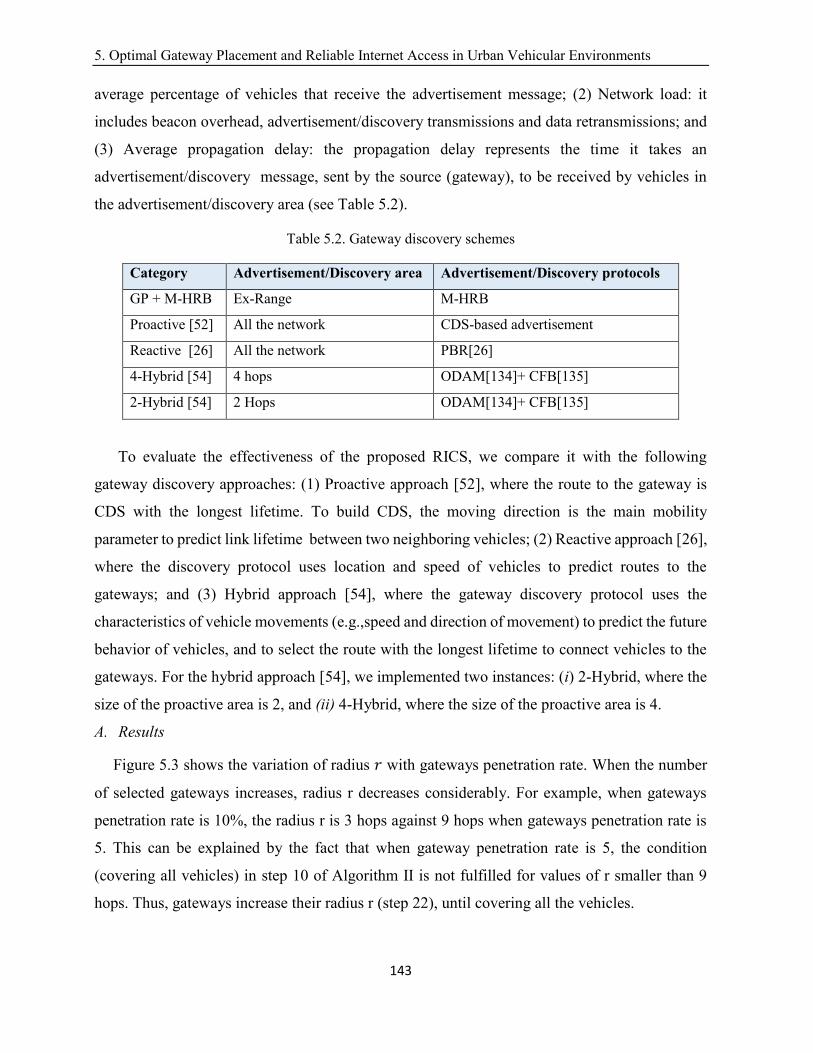
5. Optimal Gateway Placement and Reliable Internet Access in Urban Vehicular Environments
143
average percentage of vehicles that receive the advertisement message; (2) Network load: it
includes beacon overhead, advertisement/discovery transmissions and data retransmissions; and
(3) Average propagation delay: the propagation delay represents the time it takes an
advertisement/discovery message, sent by the source (gateway), to be received by vehicles in
the advertisement/discovery area (see Table 5.2).
Table 5.2. Gateway discovery schemes
Category Advertisement/Discovery area Advertisement/Discovery protocols
GP + M-HRB Ex-Range M-HRB
Proactive [52] All the network CDS-based advertisement
Reactive [26] All the network PBR[26]
4-Hybrid [54] 4 hops ODAM[134]+ CFB[135]
2-Hybrid [54] 2 Hops ODAM[134]+ CFB[135]
To evaluate the effectiveness of the proposed RICS, we compare it with the following
gateway discovery approaches: (1) Proactive approach [52], where the route to the gateway is
CDS with the longest lifetime. To build CDS, the moving direction is the main mobility
parameter to predict link lifetime between two neighboring vehicles; (2) Reactive approach [26],
where the discovery protocol uses location and speed of vehicles to predict routes to the
gateways; and (3) Hybrid approach [54], where the gateway discovery protocol uses the
characteristics of vehicle movements (e.g.,speed and direction of movement) to predict the future
behavior of vehicles, and to select the route with the longest lifetime to connect vehicles to the
gateways. For the hybrid approach [54], we implemented two instances: (i) 2-Hybrid, where the
size of the proactive area is 2, and (ii) 4-Hybrid, where the size of the proactive area is 4.
A. Results
Figure 5.3 shows the variation of radius 𝑟 with gateways penetration rate. When the number
of selected gateways increases, radius r decreases considerably. For example, when gateways
penetration rate is 10%, the radius r is 3 hops against 9 hops when gateways penetration rate is
5. This can be explained by the fact that when gateway penetration rate is 5, the condition
(covering all vehicles) in step 10 of Algorithm II is not fulfilled for values of r smaller than 9
hops. Thus, gateways increase their radius r (step 22), until covering all the vehicles.

5. Optimal Gateway Placement and Reliable Internet Access in Urban Vehicular Environments
144
Figure 5.3. Variation of minimum communication hops
Figure 5.4(a) and Figure 5.4(b) show the variation of PRR with gateways penetration rate. For
both densities (80 vehicles/kilometer and 120 vehicles/kilometer), when gateways penetration
rate increases, we observe that our approach outperforms the other approaches. For example,
PRR achieved by RICS is 100 percent when gateways penetration rate is higher than 10% and
vehicles density is 120 vehicles/kilometer, against 81% scored by 4-Hybrid and 73 % scored by
2-Hybrid. This is due to the route establishment mode which is based on the highest route
lifetime. In city environments (the wireless communication channel is very erroneous and lossy),
the links between vehicles are unreliable resulting in high packet loss. The outperformance of
RICS in terms of PRR is related to the reliability method in M-HRB; which, for each hop along
the path, selects forwarders having high reception quality [31]. In contrast, the reactive approach
ensures the lowest PRR (PRR is 40% when gateway penetration rate is 15% and vehicles density
is 120 vehicles density). The poor performance of the reactive approach in terms of PRR is related
to its route discovery method. More specifically, the routes are established based on the predicted
lifetime of links between two vehicles, where speed of neighboring vehicles is a main link
parameter. In city settings, with high channel loss due to random interference, the resulting paths
are not reliable incurring high packet loss. The worst performance of the proactive approach
(PRR is 63% when gateways penetration rate is 15% and the density is 120 vehicles/kilometer)
0
2
4
6
8
10
5 7 9 11 13 15
r
Gateways penetration rate
radius
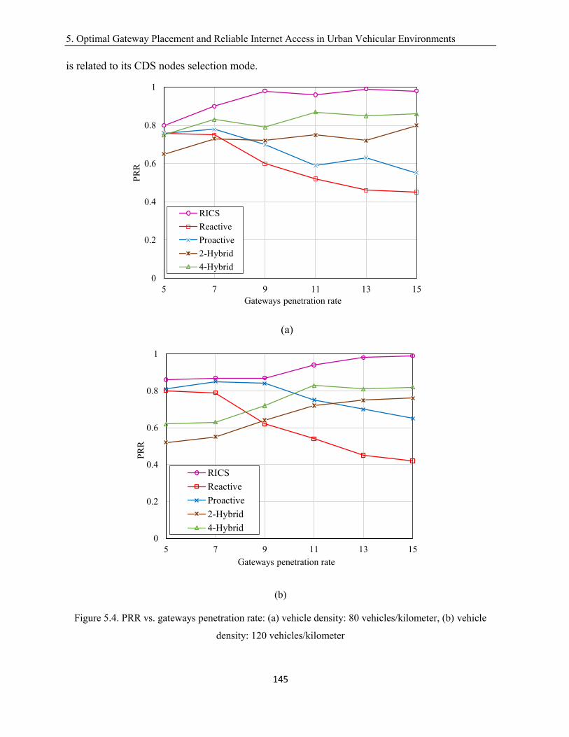
5. Optimal Gateway Placement and Reliable Internet Access in Urban Vehicular Environments
145
is related to its CDS nodes selection mode.
(a)
(b)
Figure 5.4. PRR vs. gateways penetration rate: (a) vehicle density: 80 vehicles/kilometer, (b) vehicle
density: 120 vehicles/kilometer
0
0.2
0.4
0.6
0.8
1
5 7 9 11 13 15
PR
R
Gateways penetration rate
RICS
Reactive
Proactive
2-Hybrid
4-Hybrid
0
0.2
0.4
0.6
0.8
1
5 7 9 11 13 15
PR
R
Gateways penetration rate
RICS
Reactive
Proactive
2-Hybrid
4-Hybrid
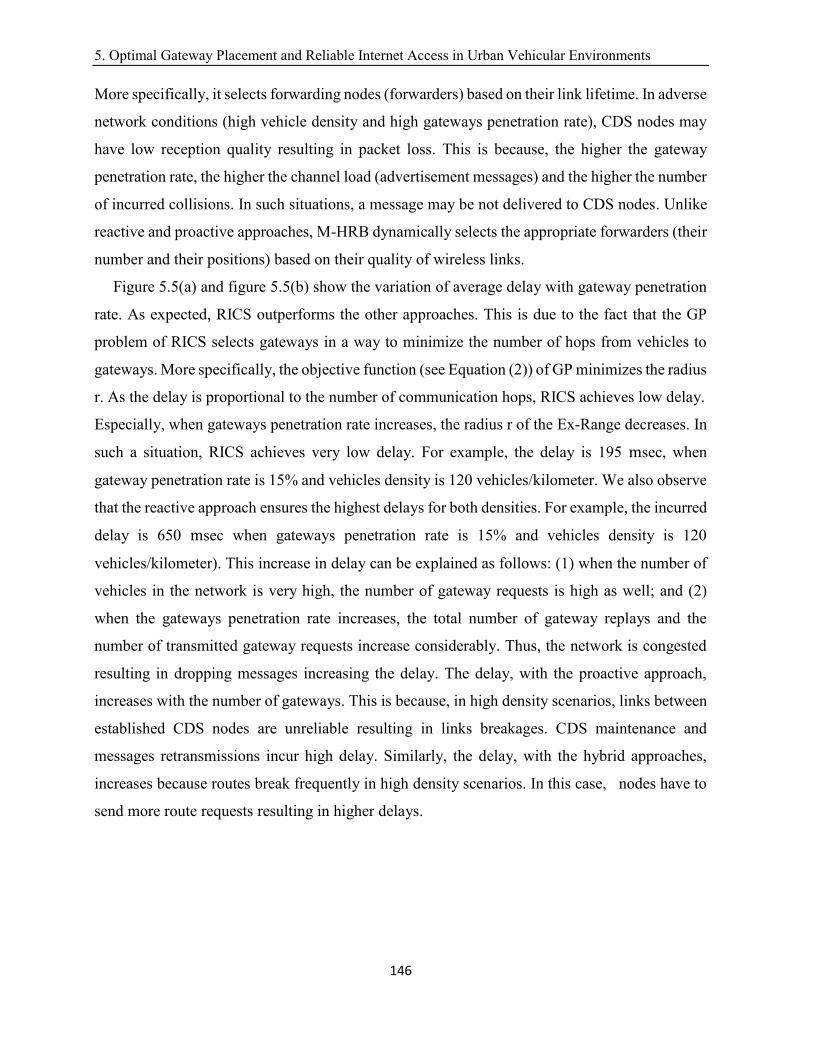
5. Optimal Gateway Placement and Reliable Internet Access in Urban Vehicular Environments
146
More specifically, it selects forwarding nodes (forwarders) based on their link lifetime. In adverse
network conditions (high vehicle density and high gateways penetration rate), CDS nodes may
have low reception quality resulting in packet loss. This is because, the higher the gateway
penetration rate, the higher the channel load (advertisement messages) and the higher the number
of incurred collisions. In such situations, a message may be not delivered to CDS nodes. Unlike
reactive and proactive approaches, M-HRB dynamically selects the appropriate forwarders (their
number and their positions) based on their quality of wireless links.
Figure 5.5(a) and figure 5.5(b) show the variation of average delay with gateway penetration
rate. As expected, RICS outperforms the other approaches. This is due to the fact that the GP
problem of RICS selects gateways in a way to minimize the number of hops from vehicles to
gateways. More specifically, the objective function (see Equation (2)) of GP minimizes the radius
r. As the delay is proportional to the number of communication hops, RICS achieves low delay.
Especially, when gateways penetration rate increases, the radius r of the Ex-Range decreases. In
such a situation, RICS achieves very low delay. For example, the delay is 195 msec, when
gateway penetration rate is 15% and vehicles density is 120 vehicles/kilometer. We also observe
that the reactive approach ensures the highest delays for both densities. For example, the incurred
delay is 650 msec when gateways penetration rate is 15% and vehicles density is 120
vehicles/kilometer). This increase in delay can be explained as follows: (1) when the number of
vehicles in the network is very high, the number of gateway requests is high as well; and (2)
when the gateways penetration rate increases, the total number of gateway replays and the
number of transmitted gateway requests increase considerably. Thus, the network is congested
resulting in dropping messages increasing the delay. The delay, with the proactive approach,
increases with the number of gateways. This is because, in high density scenarios, links between
established CDS nodes are unreliable resulting in links breakages. CDS maintenance and
messages retransmissions incur high delay. Similarly, the delay, with the hybrid approaches,
increases because routes break frequently in high density scenarios. In this case, nodes have to
send more route requests resulting in higher delays.
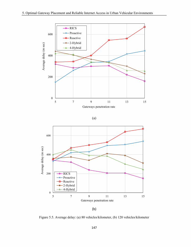
5. Optimal Gateway Placement and Reliable Internet Access in Urban Vehicular Environments
147
(a)
(b)
Figure 5.5. Average delay: (a) 80 vehicles/kilometer, (b) 120 vehicles/kilometer
0
200
400
600
5 7 9 11 13 15
Aver
age
del
ay (
m s
ec)
Gateways penetration rate
RICS
Proactive
Reactive
2-Hybrid
4-Hybrid
0
200
400
600
5 7 9 11 13 15
Aver
age
del
ay (
m s
ec)
Gateways penetration rate
RICS
Proactive
Reactive
2-Hybrid
4-Hybrid
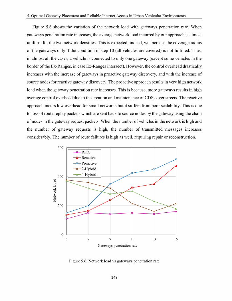
5. Optimal Gateway Placement and Reliable Internet Access in Urban Vehicular Environments
148
Figure 5.6 shows the variation of the network load with gateways penetration rate. When
gateways penetration rate increases, the average network load incurred by our approach is almost
uniform for the two network densities. This is expected; indeed, we increase the coverage radius
of the gateways only if the condition in step 10 (all vehicles are covered) is not fulfilled. Thus,
in almost all the cases, a vehicle is connected to only one gateway (except some vehicles in the
border of the Ex-Ranges, in case Ex-Ranges intersect). However, the control overhead drastically
increases with the increase of gateways in proactive gateway discovery, and with the increase of
source nodes for reactive gateway discovery. The proactive approach results in very high network
load when the gateway penetration rate increases. This is because, more gateways results in high
average control overhead due to the creation and maintenance of CDSs over streets. The reactive
approach incurs low overhead for small networks but it suffers from poor scalability. This is due
to loss of route replay packets which are sent back to source nodes by the gateway using the chain
of nodes in the gateway request packets. When the number of vehicles in the network is high and
the number of gateway requests is high, the number of transmitted messages increases
considerably. The number of route failures is high as well, requiring repair or reconstruction.
Figure 5.6. Network load vs gateways penetration rate
0
200
400
600
5 7 9 11 13 15
Net
work
Load
Gateways penetration rate
RICS
Reactive
Proactive
2-Hybrid
4-Hybrid
5. Optimal Gateway Placement and Reliable Internet Access in Urban Vehicular Environments
149
5.7. Conclusion
In this paper, we proposed an Internet access scheme to ensure multi-hop reliable paths between
gateways and vehicles in city environments. Basically, internet gateways are deployed in a way
that minimizes the communication hops subject to providing internet access to all vehicles. We
modeled the gateway placement as a k-center optimisation problem. We make use of space
dimension reduction to solve the problem in an exact time. Each gateway makes use of M-HRB
scheme to establish communication paths. The main focus of this protocol is achieving reliability
requirements of DSRC/802.11p-based broadcast. Numerical results show that, the proposed
gateway placement algorithm together with the reliable gateway discovery protocol establish
reliable communication paths in city environments.
6. Conclusion
150
Chapter 6
Conclusion
The chapter is organized as follows. Section 6.1 restates the research problem. Section 6.2
presents the thesis contributions. Section 6.3 presents perspectives and future work.
6.1. Background of the dissertation
Broadcast traffic is the cornerstone of vehicular applications. A broadcast message is not
addressed to one specific vehicle, but to all vehicles positioned in one or more hops away from
the transmitter. Indeed, to extend the reach of a broadcast message, multi-hop communications
are used.
DSRC/802.11p based broadcast has the potential to provide low latency; however, it is
defective in terms of reliability (reliability is defined as the probability of number of nodes in the
geographic surrounding of a transmitter that can successfully receive the broadcast message)
hindering the deployment IEEE DSRC/802.11p. Successful reception by every node within a
specific surrounding cannot be guaranteed because there is no suitable way to acknowledge the
reception of broadcast messages. Even if acknowledgement schemes are used, it will not be
possible to ensure that every receiver gets the message.
In multi-hop, IEEE 802.11 MAC does not offer any specific support to improve reliability,
apart from the naïve flooding scheme. However, such a solution may lead to the broadcast storm
problem resulting in unreliability (i.e., high packet loss) and delayed communication.
Conventionally, non-flooding schemes, that select forwarders, are the alternative. These schemes
must compensate for the lack of reliability. However, existing schemes have several
shortcomings.
Consequently, the development of novel schemes, that guarantee one-hop and multi-hop
message dissemination reliability while satisfying short delay requirements of vehicular
applications, is needed.
6.2. Contributions and Findings
The thesis consists of three contributions in the context of urban vehicular networks: (1)
Reliable Emergency Message Dissemination scheme (REMD); (2) Bayesian networks and

6. Conclusion
151
unipolar orthogonal Code based Reliable multi-hop Broadcast (BCRB); and (3) Reliable Internet
access System (RICS).
REMD aims to ensure high broadcast reliability while preserving low end-to-end delay for
safety applications, using message repetitions. The proposed cell concept provides fine-grained
information about wireless channel conditions. REMD exploits periodic exchanged beacons to
compute collision probability and signal power attenuation probability in each cell. By
employing curve fitting, polynomial modeling and extrapolation, REMD estimates 802.11p link
reception quality in cells. To compute optimal number of message repetitions, REMD proposes
a Max-Min optimisation problem that ensures a predefined reliability requirements at each hop.
A stochastic modeling approach is used to solve the Max-Min optimization problem. Indeed, the
number of successful receivers, in the area covered by the sender, is computed from a Poisson
Binomial distribution. Fast Fourrier Transform (FFT) enables an exact solution to the distribution
in (O(𝑛×𝑙og(𝑛))), where n is the number of cells. To combat hidden terminal problem (multi-
user interference), Uni-Polar orthogonal codes are applied to the city street network. REMD also
proposes a solution for efficient next-hop forwarders selection. REMD selects multiple
forwarders with good link reception quality together with their locations at each hop. The
forwarders use cooperative transmissions with the objective to achieve high reliability in
intermediate hops. Simulation results show that REMD outperforms existing schemes in terms
of reliability while still satisfying delay requirements of safety applications.
BCRB makes use of machine learning to accurately (compared to REMD) estimate 802.11p
link reception quality in each cell. More specifically, BCRB exploits exchanged beacons to
record training data from beacons reception state. Using this information, BCRB, based on
Bayesian networks, infers 802.11p link reception quality in each cell. Using 802.11p link
reception quality information, BCRB determines optimal number of broadcast repetitions in
order to guarantee high message reception probability for each receiver in the area covered by
the sender; it uses a binomial distribution applied to repeated transmissions at each receiver.
Furthermore, BCRB assigns zero-correlated Uni-Polar Orthogonal Codes to adjacent road
segments in order to cancel interference caused by hidden terminal problem. Like REMD, in
multi-hop, BCRB carefully selects multiple forwarders and their locations. Forwarders of same
hop cooperate with the objective to achieve high reliability in intermediate hops. Simulation
results show that both BCRB and REMD successfully achieve high reliability in lossy channel.
6. Conclusion
152
BCRB outperforms REMD in terms of communication delay and network load. This makes
BCRB a good emergency message dissemination scheme in urban environments.
RICS is an Internet access scheme that establishes multi-hop reliable paths between gateways
and vehicles in city environments. Basically, internet gateways are deployed in a way that
minimizes the number of communication hops subject to providing internet access to all vehicles.
We modeled the gateway placement as a k-center optimisation problem. We make use of a space
dimension reduction technique to solve the problem in 𝑂(𝑛2 × log(𝑛)) exact time, where n is
the number of vehicles. Each gateway makes use of BCRB to establish reliable communication
paths in city environments.
6.3. Future work
In this section, we briefly present possible/few future work as a follow-up to this thesis:
(1) A congestion control method for BCRB:
In Chapter 4, we proposed BCRB which uses broadcast repetitions to ensure high reliability.
Indeed, BCRB computes an optimal number of repetitions, according to channel conditions. In
congested scenario (i.e., high number of street lanes and the traffic density on each congested
lane is about 140veh/km), optimal repetitions may be high causing an overload of the network
when coupled with exchanged beacons. It would be desirable for BCRB to perform well even in
the presence of congestion. Therefore, a congestion control solution is required. A possible
solution would be to: (a) make use of adaptive beacon rate (based on network conditions) in order
to save bandwidth; and (b) propose a repetition cutting mechanism that prevents a sender from
repeating messages if, for example, the variation in the reliability values (i.e., the difference value
between reliability values of two successive repetitions) in smaller than a threshold value.
(2) A Bayesian network based beacon rate adaptation scheme:
Safety applications use two types of messages: (a) emergency (event driven) messages: they
are generated when an event occurs (e.g., a car accident) and are disseminated in the network to
notify vehicles of interest; and (b) beacons: they are periodic messages (broadcast) generated
several times per second to exchange information with neighbors. In chapters 3 and 4, we
proposed two emergency message dissemination schemes. Beacons are equally as important as
emergency messages. This is because the dissemination strategy usually relies on information
provided by beacons to choose forwarders, choose number of repetitions, etc. However, when
6. Conclusion
153
the network density is high, beacons may cause network congestion resulting in performance
degradation of safety applications. Therefore, a congestion control approach is required. A
possible solution would be to use Bayesian network to estimate link reception quality at different
locations. Using this information (link reception quality) as a metric, we control the beacon
generation frequency and therefore reduce the effect of congestion.
(3) A distributed gateway placement approach of RICS:
In Chapter 5, we proposed an Internet access scheme, labeled RICS, which uses a centralized
approach for gateways placement (i.e., In RICS, vehicles density information is transmitted
according to the scheme in [122] to a central server, for each time period 𝑇𝑔 (e.g., 𝑇𝑔=1 minute).
Yet, a centralized approach for traffic estimation is characterized by longer response times,
especially in big cities (longer time to exchange traffic information). Therefore, an extension to
RICS is to develop a distributed gateway placement approach. A possible solution consists of
using an online parallel approach which does not require vehicle density information but it is
based on cooperative communication among gateways. Thus, a trade-off needs to be carefully
computed to minimize overhead.
(4) RICS supports delay-constrained infotainment applications:
In Chapter 5, we proposed RICS which guarantees reliable paths to gateways. Several
infotainment applications are delay-constraint. Here, we consider that communication delay
depends on the number of communication hops. Even though, RICS aims to minimize
communication delay, it does not ensure a communication delay that is smaller than a threshold.
Therefore, an extension to RICS would be to propose a mechanism that guarantees requirement
in terms of delay. A possible solution would be to model the gateway placement as a covering
optimization problem with the objective to minimize number of gateways while ensuring the
number of communication hops is smaller than a threshold value.
References s n
154
References
[1] F. H. Shadeed and S. J. Wallaschek, “Concept of an Intelligent Adaptive Vehicle Front-Lighting
Assistance System”, in IEEE Intelligent Vehicles Symposium, pp. 1118-1121, 2007.
[2] IEEE Draft Standard for Information Technology — Telecommunications and information exchange
between systems — Local and metropolitan area networks-Specific requirements-Part 11: Wireless
LAN Medium Access Control (MAC) and Physical Layer (PHY) specifications, Amendment 6:
Wireless Access in Vehicular Environments. IEEE Std 802.11p, 2010.
[3] J. B. Kenney, “Dedicated short-range communications (dsrc) standards in the united states”, in Proc.
of the IEEE, vol. 99, no. 7, pp. 1162–1182, 2011.
[4] CAMP Vehicle Safety Communications Consortium, “Vehicle safety communications project: Task
3 final report: identify intelligent vehicle safety applications enabled by DSRC”, National Highway
Traffic Safety Administration, US Department of Transportation, 2005.
[5] G. Karagiannis, “Vehicular Networking: A Survey and Tutorial on Requirements, Architectures,
Challenges, Standards and Solutions”, in IEEE Communications Surveys & Tutorials, vol. 13, no. 4,
pp. 584-616, 2011.
[6] H. Cheng, H. Shan, and W. Zhuang, “Infotainment and road safety service support in vehicular
networking: From a communication perspective”, in Mechanical Systems and Signal Processing, vol.
25, pp. 2020-2038. 2010.
[7] M. A. Togou, L. Khoukhi and A. S. Hafid, "An Altruistic Service Channel Selection Scheme for V2V
Infotainment Applications", Accepted in IEEE International Conference on Communications (ICC),
2017.
[8] M. A. Togou, L. Khoukhi and A. S. Hafid, "IEEE 802.11p EDCA Performance Analysis for Vehicle-
to-Vehicle Infotainment Applications", Accepted in IEEE International Conference on
Communications (ICC), 2017.
[9] M. A. Togou, L. Khoukhi and A. S. Hafid, "Throughput analysis of IEEE802.11p EDCA considering
transmission opportunity for non-safety applications", in IEEE International Conference on
Communications (ICC),pp. 1-6, 2016.
[10] R. Baldessari, '' Car 2 Car Communication Consortium Manifesto”, Braunschweig, Germany, Tech.
Rep. #1.1, 2007.
[11] S. Sou and O. Tonguz, “Enhancing VANET Connectivity Through Roadside Units on Highways”,
in IEEE Trans. on Vehicular Technology, vol. 60, no. 8, pp. 3586-3602, 2011.
[12] A. Abdrabou, and W.Zhuang, “Probabilistic Delay Control and Road Side Unit Placement for
Vehicular Ad Hoc Networks with Disrupted Connectivity”, in IEEE Journal of Selected Areas in
Commu. Vol. 29, no. 1, 2011.
[13] P. Li, X. Huang, Y. Fang, and P. Lin, “Optimal placement of gateways in vehicular networks”, in
IEEE Trans. on Vehicular Technology, vol. 56, no. 6, pp. 3421–3430, 2007.
[14] A. Abdrabou, and W. Zhuang, “On a stochastic delay bound for disrupted vehicle-to-infrastructure
communication with random traffic”, in Global Telecommunications Conference (GLOBCOM),
2009.
References s n
155
[15] W. Tsung-Jung, W. Liao, and Ch. Chang, “A Cost Effective Strategy for Road-Side Unit Placement
in Vehicular Networks”, in IEEE Trans. on Communications, vol. 60, no. 8, pp. 2295-2303, 2012.
[16] B. Aslam, F. Amjad, and C. Zou, “Optimal roadside units placement in urban areas for vehicular
networks”, in Proc. IEEE ISCC, pp. 423–429, 2012.
[17] N. Lu, N. Cheng, N. Zhang, X. Shen, and J. Mark, “Connected vehicles: Solutions and challenges”,
in IEEE Internet Things Journal, vol. 1, no. 4, pp. 289–299, 2014.
[18] Z. Zheng,"Architecture of Heterogeneous Vehicular Networks. Heterogeneous Vehicular
Networks”, in Springer International Publishing, pp. 9-24, 2016.
[19] G. Araniti, C.Campolo, M. Condoluci, and A. Molinaro, “LTE for vehicular networking: a survey’’,
in IEEE Communications Magazine, vol. 51, no. 5, pp.148-157, 2013.
[20] Online:http://www.cisco.com/c/en/us/solutions/collateral/service-povider/visual-networking-index-
vni/mobile-white-paper-c11-520862.html.
[21] G. Araniti, C. Campolo, M. Condoluci, A. Iera, and A. Molinaro, “LTE for vehicular networking: a
survey”, in IEEE Communications Magazine, vol. 51, no. 5, pp. 148–157, 2013.
[22] V. Namboodiri, M. Agarwal, and L. Gao, “A study on the feasibility of mobile gateways for
vehicular ad-hoc networks”, in Proc. VANET, pp. 66-75, 2014.
[23] T. Taleb, A. Benslimane and R. Sivaraj, "Design Guidelines for a network Architecture Integrating
VANET with 3G & beyond Networks", in IEEE Journal on Selected Areas in Communications, vol.
29, no. 3, 2011.
[24] A. Benslimane, T. taleb and R. Sivaraj “Dynamic Clustering-Based Adaptive Mobile Gateway
Management in Integrated VANET–3G Heterogeneous”, in IEEE Journal on Selected Areas in
Comm., 2011.
[25] M. Alawi, A. Saeed and A. Hassan, “Cluster-based multi-hop vehicular communication with multi-
metric optimization”, in International Conference on Computer and Communication Engineering,
2012.
[26] V. Namboodiri and L. Gao, “Prediction-Based Routing for Vehicular Ad Hoc Networks”, in IEEE
Trans. on Vehicular Technology, vol. 56, no. 4, pp. 2332-2345, 2007.
[27] K. Abboud and W. Zhuang, “Stochastic Analysis of a Single-Hop Communication Link in Vehicular
Ad Hoc Networks”, in IEEE Trans. on Intelligent Transportation Systems, vol. 15, no. 5, pp. 2297-
2307, 2014.
[28] X. Shen, X. Cheng, L. Yang, R. Zhang, and B. Jiao, “Data dissemination in VANETs: A scheduling
approach”, in IEEE Trans. on Intelligent Transportation Systems, vol. 15, no. 5, pp. 2213–2223,
2014.
[29] M. Koubek, S. Rea, and D. Pesch, “Reliable broadcasting for active safety applications in vehicular
highway networks”, in Proc. IEEE VTC, pp. 1–5, 2010.
[30] K. Rostamzadeh and S. Gopalakrishnan, " Dedicated Short-Range Communications in Vehicular
Networks", in IEEE Trans. on Vehicular Technology, vol. 64, no. 10, pp. 4770-4779, 2015.
[31] W. benrhaiem, A.S. hafid, and P.k. Sahu “Multi-Hop Reliability for Broadcast-based VANET in City
Environments’’, in IEEE International Conference on Communications (ICC), 2016.
References s n
156
[32] Standard Specification for Telecommunications and Information Ex-change Roadside and Vehicle
Systems-5 GHz Band Dedicated Short Range Communications (DSRC) Medium Access Control
(MAC) and Physical Layer (PHY) Specifications, 2009.
[33] J. Sahoo, E. H. Wu, P. K. Sahu and M. Gerla, “Binary Partition Assisted MAC Layer Broadcast for
Emergency Message Dissemination in VANETs”, in IEEE Trans. On Intelligent Transportation
Systems, vol. 12, no. 3, pp. 757-770, 2011.
[34] Y. Yang, and L. Chou, “Position-based Adaptive Broadcast Scheme for Inter-Vehicle
Communications”, in Proc. IEEE International Conference on Communications (ICC), pp. 410-414,
2008.
[35] E. Falk, “A linear Mini-Max Problem”, Mathematical Programming, pp. 169-188, 1973.
[36] W. Benrhaiem, A. Hafid and P. K. Sahu, "Optimal Gateway Placement and Reliable Internet Access
in Urban Vehicular Environments", in IEEE 41st Conference on Local Computer Networks (LCN),
pp. 662-670, 2016.
[37] Y. Mylonas, M. Lestas, A. Pitsillides, P. Ioannou and V. Papadopoulou, "Speed Adaptive
Probabilistic Flooding for Vehicular Ad Hoc Networks", in IEEE Trans. on Vehicular Technology,
vol. 64, no. 5, pp. 1973-1990, 2015.
[38] H. Lim and C. Kim, "Flooding in wireless ad hoc networks”, in Computer Communications Journal,
vol. 24, no. 3-4, pp. 353-363, 2001.
[39] K. Zheng, Q. Zheng, P. Chatzimisios, W. Xiang and Y. Zhou, “Heterogeneous Vehicular
Networking: A Survey on Architecture, Challenges, and Solutions”, in IEEE Communications
Surveys & Tutorials, vol. 17, no. 4, pp. 2377-2396, 2015.
[40] Yu. Qiangyuan and G. Heijenk, “Abiding Geocast for Warning Message Dissemination in Vehicular
Ad Hoc Networks”, in Proc. IEEE International Conference on Communications (ICC) workshop,
pp. 400-404, 2008.
[41] Y. T. Yang and L. D. Chou, “Position-based Adaptive Broadcast Scheme for Inter-Vehicle
Communications”, in Proc. IEEE International Conference on Communications (ICC), pp. 410-414,
2008.
[42] F. J. Ros, P. M. Ruiz and I. Stojmenovic, ”Acknowledgment-based broadcast scheme forreliable and
efficient data dissemination in vehicular ad-hoc networks”, in IEEE Trans. Mobile Computing, vol.
11, no. 1, pp. 33 – 46, 2012.
[43] Y. Mylonas, M. Lestas, A. Pitsillides, P. Ioannou and V. Papadopoulou, “Speed Adaptive
Probabilistic Flooding for Vehicular Ad Hoc Networks”, in IEEE Trans. on Vehicular Technology,
vol. 64, no. 5, pp. 1973-1990, 2015.
[44] L. Bononi and M. D. Felice, “A cross layered MAC and clustering scheme for efficient
broadcast in VANETs”, in Proc. IEEE MASS, pp. 1 -8, 2007.
[45] D. Shin, H. Yoo, and D. Kim, ‘‘EMDOR: Emergency message dissemination with ACK-overhearing
based retransmission”, in Proc. IEEE ICUFN, pp. 230–234, 2009.
[46] Q. Xu, T. Mak, J. Ko, and R. Sengupta, “Medium access control scheme design for vehicle-to-vehicle
safety messages”, in IEEE Trans. Veh. Technol., vol. 56, no. 2, pp. 499–518, Mar. 2007.
[47] F. Chung, J. Salehi, V. Wei, B. Res, and N. Morristown, “Optical orthogonal codes: design, analysis
and applications”, Information Theory, IEEE Trans. vol. 35, no. 3, pp. 595–604, 1989.

References s n
157
[48] Y. Hongseok, K. Dongkyun, “Repetition-based cooperative broadcasting for vehicular ad-hoc
networks”, in Computer Communications, Vol. 34, no. 15, pp. 1870-1882. 2011.
[49] L. Zhang, B. Hassanabadi and S. Valaee, “Cooperative Positive Orthogonal Code-Based Forwarding
for Multi-Hop Vehicular Networks”, in IEEE Trans. on Wireless Communications, vol. 13, no. 7,
pp. 3914-3925, 2014.
[50] M. Bechler, L.Wolf, O. Storz and W. J. Franz, “Efficient discovery of Internet gateways in future
vehicular communication systems”, in Vehicular Technology Conference (VTC), pp. 965-969 vol. 2,
2003.
[51] A. Adama Ba, A. Hafid and J. Drissi. “Broadcast Control-Based Routing Protocol for Internet Access
in VANETS”, in IEEE WCNC. 2011.
[52] Ngo, Ch. Trung, and O. Hoon. “A Gateway Discovery Approach Using Link Persistence Based
Connected Dominating Sets for Vehicular Ad Hoc Networks”, in Ad- hoc, Mobile, and Wireless
Network. Springer Berlin Heidelberg, pp. 305-316, 2013.
[53] M.Alawi, “Simplified gateway selection scheme for multi-hop relay in vehicular ad hoc network”,
in International Journal of Communication Systems, vol. 27. no. 12, pp. 3855-3873, 2014.
[54] A. Benslimane, S. Barghi, and Ch.Assi. “An efficient routing protocol for connecting vehicular
networks to the Internet”, in Pervasive and Mobile Computing, vol.7. pp. 98-113, 2011.
[55] L. galati Giordano and L. Reggiani, “Vehicular Technologies Deployment and Applications”, in
Tech, 2013.
[56] V. Vazirani. “Approximation algorithms”, in Springer Science & Business Media, 2013.
[57] H. Hartenstein and L. P. Laberteaux, "A tutorial survey on vehicular ad hoc networks," in IEEE
Communications Magazine, vol. 46, no. 6, pp. 164-171, 2008.
[58] N. Wisitpongphan, O. Tonguz, J. Parikh, P. Mudalige, F. Bai, and V. Sadekar,"Broadcast storm
mitigation techniques in vehicular ad hoc networks," in IEEE Wireless Communications, vol. 14,
no. 6, pp. 84-94, 2007.
[59] F. J. Ros, P. M. Ruiz, and I. Stojmenovic,” Acknowledgment-based broadcast scheme forreliable and
efficient data dissemination in vehicular ad-hoc networks”, in IEEE Transaction on Mobile
Computing. Vol. 11, no. 1, pp. 33 – 46, 2012.
[60] G. Korkmaz, E. Ekici, and F. Ozguner, “Black-Burst-Based Multi-hop Broadcast Schemes for
Vehicular Networks,” in IEEE Trans. Veh.Tech., vol. 56, no. 5, pp. 3159-3167, 2007.
[61] Y. Bi, H. Zhao, and X. Shen, “A directional broadcast scheme for emergency messages exchange in
inter-vehicle communications”, in Proc. IEEE International Conference on Communications ICC,
pp. 1–5, 2009.
[62] H. Yoo and D. Kim, “ROFF: RObust and fast forwarding in vehicular ad-hoc networks”, in IEEE
Trans. on Mobile Comput., vol. 14, no. 7, pp. 1490-1502, 2014.
[63] C. Suthaputchakun, M. Dianati, and Z. Sun, “Trinary partitioned black-burst based broadcast scheme
for time-critical emergency message dissemination in VANETs,” in IEEE Trans. Veh. Technol., vol.
63, no. 6, pp. 2926-2940, 2014.
[64] Y. Bi, H. Shan, X. Shen, N. Wang, and H. Zhao, “A multi-hop broadcast scheme for emergency
message dissemination in urban vehicular ad hoc networks,” in IEEE Trans. Intell. Trans p. Sys t.,
vol. 17, no. 3, pp. 736-750, 2016.
References s n
158
[65] M. A. Togou, A. Hafid and L. Khoukhi, “SCRP: Stable CDS-Based Routing Protocol for Urban
Vehicular Ad Hoc Networks”, in IEEE Transactions on Intelligent Transportation Systems, vol. 17,
no. 5, pp. 1298-1307, 2016.
[66] M. Sh. Rayeni, A. Hafid and P. K. Sahu, “Dynamic spatial partition density-based emergency
message dissemination in VANETs”, in Vehicular Communications, Vol. 2, no. 4, pp. 208-222,
October 2015.
[67] Y. Bi, L. X. Cai, and X. Shen, “Efficient and reliable broadcast in Intervehicle communications
networks: A cross layer approach,” in IEEE Trans. Veh. Technol., vol. 59, no. 5, pp. 2404–2417,
2010.
[68] M. Li, Z. Kai, W. Lou, “Opportunistic broadcast of event driven warning messages in vehicular ad
hoc networks with lossy links”, in Computer Networks, vol. 55, no. 5, pp. 2443–2464, 2011.
[69] D. Shin, H. Yoo, and D. Kim, ‘‘EMDOR: Emergency message dissemination with ACK-overhearing
based retransmission,’’ in Proc. IEEE ICUFN, pp. 230–234, 2009.
[70] G. Korkmaz, E. Ekici and F. Ozguner, “An Efficient Fully Ad-Hoc Multi- Hop Broadcast Protocol
for Inter-Vehicular Communication Systems”, in IEEE International Conference on
Communications, pp. 423-428, 2006.
[71] J.-F. Lee, C.-S. Wang, and M.-C. Chuang, “Fast and reliable emergency message dissemination
mechanism in vehicular ad hoc networks,” in Proc. IEEE Wireless Commun. Netw., pp. 1–6, 2010.
[72] F. Farnoud and S. Valaee, "Repetition-based broadcast in vehicular ad hoc networks in Rician
channel with capture," in IEEE INFOCOM, Phoenix, AZ, pp. 1-6., 2008.
[73] F. Farnoud and S. Valaee, “Reliable broadcast of safety messages in vehicular ad hoc networks,” in
IEEE INFOCOM. pp. 226–234, 2009.
[74] Ba, Amadou Adama and A. Hafid “Protocole de routage basé sur des passerelles mobiles pour un
accès Internet dans les réseaux véhiculaires“, 2011.
[75] K.Abrougui, A. Boukerche, R.Werner and N. Pazzi. "Location-Aided Gateway Advertisement and
Discovery Protocol for VANets", in IEEE Transactions on Vehicular technology, 2010.
[76] S. Bastani, B. Landfeldt and L. Libman, “On the reliability of safety message broadcast in urban
vehicular ad hoc networks”, in Proc. of the 14th ACM international conference on Modeling, analysis
and simulation of wireless and mobile systems, pp. 307-316, 2011.
[77] M. Hassan, H. Vu, and T. Sakurai, “Performance Analysis of the IEEE 802.11 MAC Scheme for
DSRC Safety Applications”, in IEEE Trans. on Vehicular Technology, vol. 60, no. 8, pp. 3882-
3896, 2011.
[78] Q. Xu, T. Mak, and R. Sengupta, “Vehicle-to-vehicle safety messaging in DSRC”, in Proc. ACM
Int. Workshop VANET, pp. 19–28, 2004.
[79] Y. Bi, L. Cai, X. Shen, and H. Zhao, “A Cross Layer Broadcast Scheme for Multi-hop Emergency
Message Dissemination in InterVehicle Communication”, in Proc. IEEE Int’l Conf. Comm. (ICC),
pp. 1-5, 2010.
[80] M. Almulla, Y. Wang, A. Boukerche and Z. Zhang, “Design of a Fast Location-Based Handoff
Scheme for IEEE 802.11 Vehicular Networks”, in IEEE Transactions on Vehicular Technology,
vol. 63, no. 8, pp. 3853-3866, 2014.
References s n
159
[81] A. Bazzi, A. Zanella and B. M. Masini, "An OFDMA-Based MAC Protocol for Next-Generation
VANETs," in IEEE Trans. on Vehicular Technology, vol. 64, no. 9, pp. 4088-4100, 2015.
[82] S. Ni, Y. Tseng, Y. Chen, and J. Sheu, “The broadcast storm problem in a mobile ad hoc network”,
in Proc. ACM Int’l Conf. on Mobile Computing and Networking (MOBICOM), pp. 151–162, 1999.
[83] M. Torrent-Moreno, D. Jiang, and H. Hartenstein, “Broadcast reception rates and effects of priority
access in 802.11-based vehicular ad hoc networks”, in Proc. 1st ACM Int. Workshop VANET, pp.
10–18, 2004.
[84] J. H. Chung and K. Yang, “New Families of Optimal Variable-Weight Optical Orthogonal Codes
With High Weights”, in IEEE Trans. on Information Theory, vol. 61, no. 8, pp. 4511-4517, 2015.
[85] A. Kotsialos, M. Papageorgiou, C. Diakaki, Y. Pavlis and F. Middelham, “Traffic flow modeling of
large-scale motorway networks using the macroscopic modeling tool METANET”, in IEEE Trans.
on Intelligent Transportation Systems, vol. 3, no. 4, pp. 282-292, 2002.
[86] R. Chen, W. L. Jin and A. Regan, "Broadcasting safety information in vehicular networks: issues
and approaches", in IEEE Network, vol. 24, no. 1, pp.20-25, 2010.
[87] S. Johnson, “A New Upper Bound for Error-correcting Codes”, in IEEE Transactions on Information
Theory, vol. 8, no. 3, pp. 203–207, 1962.
[88] R. K. Schmidt, T. Köllmer, T. Leinmüller, B. Böddeker, and G. Schäfer, "Degradation of
Transmission Range in VANETs caused by Interference", in PIK- Praxis der Informations
verarbeitung und Kommunikation: Special issue on Mobile Ad Hoc networks, 2009.
[89] W. Kumar, S. Bhattacharya, B. Qazi and J. Elmirghani. "A Vacation-Based Performance Analysis
of an Energy-Efficient Motorway Vehicular Communication System", in IEEE Trans. on vehicular
Technology, Vol.63, No.4, 2014
[90] T. S. Rappaport, “Wireless Communications, Principles and Practice”. Englewood Cliffs, NJ, USA:
Prentice-Hall, 1999.
[91] Guest, Ph.George, and Philip George Guest. “Numerical methods of curve fitting”. Cambridge
University Press, 2012.
[92] J. Yoo, B. S. C. Choi, and M. Gerla, “An opportunistic relay scheme for vehicular road-side access
with fading channels”, in Proc. IEEE ICNP, pp. 233–242, 2010.
[93] R. J. Vanderbei, “Linear programming”. Springer, 2015.
[94] E. Falk, “A linear Mini-Max Problem”, Mathematical Programming, pp. 169-188, 1973.
[95] W. Hoeffding. "On the distribution of the number of successes in independent trials" The Annals of
Mathematical Statistics, pp.713-721. 1956.
[96] L. Le Cam. “The Poisson approximation to the Poisson binomial distribution”. Ann. Math. Statist.
31, pp. 737-740, 1960.
[97] Y. Hong, “On computing the distribution function for the Poisson binomial distribution”, in
Computational Statistics & Data Analysis, 59, pp. 41-51, 2013.
[98] Y. Hong. “On computing the distribution function for the sum of independent and non-identical
random indicators”, Dep. Statit., Virginia Tech, Blacksburg, VA, USA, Tech. Rep. 11_2. 2011.
[99] C. Thorpe and L. Murphy, "A Survey of Adaptive Carrier Sensing Mechanisms for IEEE 802.11
Wireless Networks", in IEEE Communications Surveys & Tutorials, vol. 16, no. 3, pp. 1266-1293,
2014.
References s n
160
[100] SUMO – Simulation of Urban Mobility (February, 2014). Available: http://sumo.sourceforge.net
[101] OMNET++ the open simulator. (February 2014) Available: http://www.omnetpp.org
[102] C. Sommer. (February, 2014). Veins-Vehicles in network simulation. Available:
http://www.veins.car2x.org/
[103] W. Hoeffding. On the distribution of the number of successes in independent trials. Annals of
Mathematical Statistics, 27:713–721, 1956.
[104] Tomas-Gabarron, J. B., Egea-Lopez, E., Garcia-Haro, J., R. Murcia-Hernandez, “Performance
evaluation of a CCA application for VANETs using IEEE 802.11p”, in Communications
Workshops (ICC), 2010
[105] Q. Xu, R. Segupta, D. Jiang and D. Chrysler, “Design and analysis of highway safety
communication protocol in 5.9 GHz dedicated short range communication spectrum”, in IEEE
Vehicular Technology Conference ( VTC), pp. 2451-2455 vol. 4, 2003.
[106] W. Benrhaiem, A. Hafid, and P. Sahu, “A Reliable Emergency Message Dissemination Scheme
for Urban Vehicular Networks”, Technical report #1378, Dept. of Computer Science and
Operational Research, University of Montreal, 2017.
[107] K. Abboud and W. Zhuang, "Stochastic Analysis of a Single-Hop Communication Link in
Vehicular Ad Hoc Networks", in IEEE Trans. on Intelligent Transportation Systems, vol. 15, no.
5, pp. 2297-2307, 2014.
[108] J. Pan, I. S. Popa and C. Borcea, “DIVERT: A Distributed Vehicular Traffic Re-Routing System
for Congestion Avoidance”, in IEEE Trans. on Mobile Computing, vol. 16, no. 1, pp. 58-72, 2017.
[109] J. Yu, “SenSpeed: Sensing Driving Conditions to Estimate Vehicle Speed in Urban Environments”,
in IEEE Trans. on Mobile Computing, vol. 15, no. 1, pp. 202-216, 2016.
[110] J. Pearl, “Probabilistic Reasoning in Intelligent Systems: Networks of Plausible Inference”, Morgan
Kaufmann, 2014.
[111] P. Spirtes, C. N. Glymour and R. Scheines, “Causation, prediction, and search”, in MIT press, 2000.
[112] MI. Jordan. “Learning in graphical models”. Springer Science & Business Media. Vol. 89. 1998.
[113] H. J. Suermondt, “Explanation in Bayesian belief networks”. 1992.
[114] S. Hoogendoorn, and P. Bovy, “Gas-kinetic model for multilane heterogeneous traffic flow”,
in Transportation Research Record: Journal of the Transportation Research Board, pp. 150-159,
1999.
[115] M. L. McHugh, “The Chi-square test of independence”, in Biochem Med, vol. 23, n. 2, pp. 125–
31, 2013.
[116] R. Neal, and G. Hinton, “A view of the EM algorithm that justifies incremental, sparse, and other
variants”, Learning in graphical models Springer Netherlands, pp. 355-368, 1998.
[117] B. Hassanabadi and S. Valaee, “Reliable Network Coded MAC in Vehicular Ad-Hoc Networks”,
in IEEE Vehicular Technology Conference, pp. 1-5, 2010.
[118] D. Stanislawski, “The Grid-Pattern Town”, Geog. Rev., pp. 105-120, 1946.
[119] M. L. Belozerskaya, Kenneth, “Ancient Greece: art, architecture, and history”, Los Angeles: Getty
Publications, 2004.
References s n
161
[120] S. Sachs and P. Varaiya, “A communication system for the control of automated vehicles”,
California PATH Research Rep. TECH MENFDMO-93-05, 1993
[121] Dedicated Short Range Communications (DRSC) Home. [Online].
Available: http://www.leearmstrong.com/Dsrc/DSRCHomeset.htm.
[122] P. k. Sahu, A. Hafid, and S. Cherkaoui. " DMAP: Density Map Service in City Environments”, in
IEEE Transactions on Intelligent Transportation Systems,vol 16, no. 5, pp. 2862 – 2877, Oct. 2015.
[123] R. S. Garfinkel and G. L. Nemhauser. “Integer programming”, in Wiley, Vol. 4, New York 1972.
[124] A. Lo, J. Zhou, I. Niemegeers,”Simulation-based Analysis of TCP over beyond 3G Cellular Multi-
Hop Networks”, in Proc. IEEE PIMRC, 2006.
[125] D. Soldani and S. Dixit, “Wireless relays for broadband access, radio communications series”, in
IEEE. Communications Magazine, vol. 46, no. 3, pp. 58-66. 2008.
[126] Online: http://kolntrace.project.citi-lab.fr/
[127] M. Fellows and H. Fernau, “Facility Location Problems: A Parameterized View”, University of
Newcastle University Drive, Australia.
[128] P. Brass, C. Knauer, H-S. Na, C-S. Shin and A. Vigneron, “Computing k-centers on a line”.
Technical report.arXiv preprint arXiv:0902.3282, 2009.
[129] C. S. Sorzano, J. Vargas, and A. P. Montano, “A survey of dimensionality reduction techniques,”
arXiv preprint arXiv:1403.2877, 2014.
[130] M. A. Carreira-Perpinan, “A review of dimension reduction techniques”, Technical report CS-96-
09, Department of Computer Science, University of Sheffield, 1997.
[131] Online: www.openstreetmap.org/
[132] S. Sachs and P. Varaiya, “A communication system for the control of automated vehicles”.
California PATH Research Rep. TECH MENFDMO-93-05, 1993
[133] B. Aslam, F. Amjad, and C. Zou, ‘‘Optimal fselective ts placement in urban areas for vehicular
networks,’’ in Proc. IEEE ISCC, 2012, pp. 000423--000429.
[134] A. Benslimane, “Optimized Dissemination of Alarm Messages in Vehicular Ad-Hoc Networks
(VANET),” in Proc. 7th IEEE Int’l. Conf. High Speed Networks and Multimedia Commun, pp.
655–66, 2004.
[135] H. Füßler, J. Widmger, M. Käsemann, M. Mauve, and H. Hartenstein, “Contention-based
forwarding for mobile ad-hoc networks,” in Ad-Hoc Networks, vol. 1, no. 4, pp. 351-369, 2003.
[136] G. Karagiannis, “Vehicular Networking: A Survey and Tutorial on Requirements, Architectures,
Challenges, Standards and Solutions”, in IEEE Communications Surveys & Tutorials, vol. 13, no.
4, pp. 584-616, 2011.
[137] R. Brignolo, G. Vivo, F. Visintainer, F. Belarbi, “Use cases, functional specifications and safety
margin applications for the SAFESPOT Project”, SAFESPOT Integrated Project, deliverable #
IST-4-026963-IP, 2010.
[138] URL: http://www.safespot-eu.org/use_cases.html
[139] F. Schmidt-Eisenlohr, “Interference in Vehicle-to-Vehicle Communication Networks - Analysis,
Modeling, Simulation and Assessment,” Ph.D. dissertation, Karlsruhe Institute of Technology
(KIT), 2010.

References s n
162
[140] H. T. Cheng, H. Shan, and W. Zhuang, “Infotainment and road safety service support in vehicular
networking: From a communication perspective,” in Mech. Syst. Signal Process., Special Issue
Integr. Veh. Dyn., vol. 25, no. 6, pp. 2020–2038, 2011.