Embed Size (px)
Citation preview
N° d’ordre Année 2007
THESE
présentée devant
L’INSTITUT NATIONAL DE SCIENCES APPLIQUEES DE LYON ET
YEUNGNAM UNIVERSITY
pour obtenir
LE GRADE DE DOCTEUR
FORMATION DOCTORALE : SIDS spécialité ISSI ECOLE DOCTORALE : ELECTRONIQUE, ELECTROTECHNIQUE, AUTOMATIQUE
PAR
MIN-SU KIM
Wavelet Transform Based Digital Watermarking for 3-D Surface Meshes and Mesh Sequences
Soutenue le 26 février 2007 devant la Commission d’Examen Jury :
Francis SCHMITT Rapporteur Ki-Ryong KWON Rapporteur Isabelle MAGNIN Examinateur Kook-Yeol YOO Examinateur Rémy PROST Co-Directeur de thèse Ho-Youl JUNG Co-Directeur de thèse
Cette thèse a été préparée au,
Centre de Recherche Et d’Applications en Traitement de l’Image et du Signal (CREATIS UMR CNRS 5515) de l’INSA LYON et l’UCBL Multimedia Signal Processing (MSP) Laboratory of Yeungnam University


SIGLE ECOLE DOCTORALE NOM ETCOORDONNEES DU RESPONSABLE
CHIMIE DE LYON M. Denis SINOUUniversité Claude Bernard Lyon 1Lab Synthèse Asymétrique UMR UCB/CNRS 5622Bât 308, 2ème étage
M. Denis SINOU 43 bd du 11 novembre 191869622 VILLEURBANNE CedexTél : 04.72.44.81.83 Fax : [email protected]
E2MC ECONOMIE, ESPACE ET M. Alain BONNAFOUSMODELISATION DES COMPORTEMENTS Université Lyon 2
14 avenue BerthelotMRASH M. Alain BONNAFOUS
M. Alain BONNAFOUS Laboratoire d’Economie des Transports69363 LYON Cedex 07Tél : [email protected]
E.E.A. ELECTRONIQUE, ELECTROTECHNIQUE, M. Daniel BARBIERAUTOMATIQUE INSA DE LYON
Laboratoire Physique de la MatièreM. Daniel BARBIER Bâtiment Blaise Pascal
69621 VILLEURBANNE CedexTél : 04.72.43.64.43 Fax : [email protected]
E2M2 EVOLUTION, ECOSYSTEME, M. Jean-Pierre FLANDROISMICROBIOLOGIE, MODELISATION UMR 5558 Biométrie et Biologie Evolutivehttp://biomserv.univ-lyon1.fr/E2M2 Equipe Dynamique des Populations Bactériennes
Faculté de Médecine Lyon-SudM. Jean-Pierre FLANDROIS Laboratoire de Bactériologie BP
1269600 OULLINSTél : 04.78.86.31.50 Fax : [email protected]
EDIIS INFORMATIQUE ET INFORMATION POUR M. Lionel BRUNIELA SOCIETE INSA DE LYONhttp://www.insa-lyon.fr/ediis EDIIS, Bâtiment Blaise PascalM. Lionel BRUNIE 69621 VILLEURBANNE Cedex
Tél : 04.72.43.60.55 Fax : [email protected]
EDISS INTERDISCIPLINAIRE SCIENCES-SANTE M. Alain Jean COZZONEhttp://www.ibcp.fr/ediss IBCP (UCBL1)
7 passage du VercorsM. Alain Jean COZZONE 69367 LYON Cedex 07
Tél : 04.72.72.26.75 Fax : [email protected]
MATERIAUX DE LYON M. Jacques JOSEPHEcole Centrale de LyonBât F7 Lab. Sciences et Techniques des Matériaux et des Surfaces
M. Jacques JOSEPH 36 Avenue Guy de Collongue BP 16369131 ECULLY CedexTél : 04.72.18.62.51 Fax : [email protected]
Math IF MATHEMATIQUES ET INFORMATIQUE M. Franck WAGNERFONDAMENTALE Université Claude Bernard Lyon1http://www.ens-lyon.fr/MathIS Institut Girard Desargues UMR 5028 MATHEMATIQUES
Bâtiment Doyen Jean BraconnierM. Franck WAGNER Bureau 101 Bis, 1er étage
69622 VILLEURBANNE CedexTél : 04.72.43.27.86 Fax : 04.72.43.16.87
MEGA MECANIQUE, ENERGETIQUE, GENIE M. François SIDOROFFCIVIL, ACOUSTIQUE Ecole Centrale de Lyonhttp://www.lmfa.ec- Lab. Tribologie et Dynamique des Systêmeslyon.fr/autres/MEGA/index.html Bât G8, 36 avenue Guy de Collongue, BP 163
69131 ECULLY CedexM. François SIDOROFF Tél : 04.72.18.62.14 Fax : 04.72.18.65.37

Abstract
This thesis deals with digital watermarking methods for copyright protection of3-D surface meshes and mesh sequences. The proposed methods are based on waveletanalysis of the geometry of the surface meshes, or on wavelet analysis of the vertexcoordinate signals along the time axis.
3-D static meshes
The first proposal embeds the watermark into the L2 norm of the geometric waveletcoefficients (vectors) by using spread spectrum method. The Cartesian coordinatesshould be converted into the spherical coordinates. The method can directly processsemi-regular or irregular meshes. For the invariance of the wavelet coefficients after in-verse wavelet transform, it is necessary to synchronize the connectivity by re-orderingthe vertex indexes from a reference vertex. This approach ensures the blind detectionwhich does not require the original meshes during watermark extraction procedures.
The second proposal is based on a statistical approach. The histogram of the L2norm of scale coefficients (approximation mesh) was divided into regular bins. The mean(or the variance) of each bin is modified according to the watermark by a non-linearexponential transformation. The watermark can be extracted from the distribution ofthe scale coefficients after wavelet analysis, as well as from the distribution of vertexnorms of the watermarked meshes without using the wavelet analysis. This proposal ismore robust against topological attacks than the first one.
3-D mesh sequence (3-D dynamic meshes with fixed connectivity, 3D+t)
The first proposal is based on the vertex coordinate signals along the time axis, andthe second uses the vertex norm signals along the time axis of the mesh sequence. Asa result, the number of signals to decompose by wavelet analysis equals three times ofthe number of vertices for the first proposal and equals the number of vertices for thesecond.
The first proposal embeds the watermark into the temporal wavelet (high frequency)coefficients of each coordinates of the sequence. In this proposal, the histogram of L2norm of the scale (low frequency) coefficients is divided into distinct bins with equalrange according to their magnitude. Since the distribution of temporal wavelet coeffi-
cients can be approximated to Laplacian distribution, the variance of the distributionof each bin is asymmetrically modified according to the watermark bits to be embed-ded. This method is robust against frame-averaging attack and frame-by-frame attacks.
In the second proposal, the Cartesian coordinates of the vertices are converted intothe spherical coordinates and the L2 norm of each vertex is wavelet transformed alongthe time axis. Similar to the first proposal, the variance of the distribution of waveletcoefficients is modified according to the watermark. This proposal which uses L2 normoutperforms the first proposal in terms of the invisibility of the watermark and therobust against rotation attacks.
Finally, we propose the method which embeds the watermark into both wavelet andscale coefficients. This method allows extracting the watermark from the distributionof scale and wavelet coefficients of each frame. In addition, it is possible to extract thewatermark from a single frame in spatial domain.
Note that all of our proposals do not require the mesh sequence (or original meshes)in the procedures of watermark extraction.
The robustness against geometrical attacks (additive noise on the vertex coordi-nates, uniform vertex coordinates quantization, low-pass filtering, cropping, rotation,translation, scaling, frame-dropping for mesh sequence), and topological attacks (ran-dom vertex index reordering, simplification, subdivision) are evaluated on the semi-regular and irregular meshes.
Keywords3-D Surface Meshes, 3-D Mesh Sequence, Digital Watermarking, Copyright Protection,Wavelet, Blind Detection
Resume
Cette these propose des methodes de protection des droits d’auteur, par tatouagesnumeriques, relatifs a des objets en trois dimensions representes par leurs maillagestriangulaires surfaciques statiques ou dynamiques. Les approches proposees utilisentla decomposition en ondelettes du maillage ou des signaux associes a l’evolution descoordonnees des sommets de ce maillage au cours du temps.
Maillages statiques 3D
Une premiere proposition, inspiree des methodes dite ‘spread spectrum’, incorporele tatouage dans le module des coefficients (vecteurs) d’ondelettes geometriques. Lemaillage peut etre semi regulier ou irregulier. Elle necessite la transformation des co-ordonnees cartesiennes des sommets en coordonnees spheriques. Apres la transformeeen ondelettes inverse, les index des sommets sont reordonnes, a partir d’un sommetde reference, afin d’assurer une invariance des coefficients d’ondelettes, necessaire al’extraction du tatouage. Cette approche garantit l’extraction du tatouage sans le mail-lage original.
Une deuxieme proposition utilise une approche statistique. Elle incorpore le tatouagedans le module des coefficients d’echelles (maillage d’approximation), par intervalles deleur histogramme. La moyenne (ou la variance) de chaque intervalle est modifiee par letatouage a l’aide d’une transformation non lineaire exponentielle. Le tatouage peut etreextrait, sans le maillage original, a partir de la distribution des coefficients d’echellesou directement sur le maillage en pleine resolution (domaine spatial). Cette deuxiemeproposition est plus robuste aux attaques topologiques que la precedente.
Sequence de maillages 3D (Maillages dynamiques a connectivite constante,3D+t)
Dans une premiere approche, les evolutions temporelles des coordonnees des som-mets sont assimilees a trois signaux independants et, dans une deuxieme approche, lemodule de chaque sommet est un signal. Ainsi, le nombre de signaux a decomposer surune base d’ondelettes est trois fois le nombre de sommets pour la premiere approcheet seulement egal au nombre de sommets dans la seconde.
Pour la premiere approche le tatouage est incorpore dans les coefficients d’ondelettes
temporels de chaque coordonnee de la sequence. Les sommets du maillage sont classesdans des intervalles reguliers de l’histogramme des moyennes temporelles du module descoefficients d’echelles (basses frequences). Le tatouage modifie la distribution Laplaci-enne des coefficients d’ondelettes (hautes frequences) de chacune des classes, de faconasymetrique par une transformation non lineaire exponentielle. Dans chaque intervalle,la variance est modifiee par le tatouage. Cette approche est robuste face aux simplifi-cations par moyenne de trames et aux attaques individuelles de chacune des trames.
Pour la deuxieme approche les coordonnees cartesiennes des sommets sont trans-formees en coordonnees spheriques et le module de chaque sommet est un signaldecompose en ondelettes. Le tatouage est incorpore sur les coefficients d’ondelettes desmodules de facon analogue a la methode precedente. Une variante de cette methodeincorpore, en plus, le tatouage dans les coefficients d’echelles. Elle permet l’extractiondu tatouage a l’aide des coefficients d’echelles et d’ondelettes temporels de l’ensembledes trames ou a l’aide d’une seule trame dans le domaine spatial.
On notera que, aussi bien pour les maillages dynamiques que statiques, toutes lesmethodes proposees permettent l’extraction du tatouage sans le maillage original (ex-traction aveugle).
La robustesse, face a des attaques geometriques (addition de bruit sur les coor-donnees des sommets, quantification des coordonnees des sommets, filtrage geometriquepasse-bas, selection d’une partie du maillage, rotations, translations, changements d’echelle,suppression de trame pour les maillages dynamiques) et topologiques (reordonnancementdes index des sommets, simplification, subdivision) est evaluee sur des maillages semireguliers et irreguliers.
Mots clesMaillage surfacique 3D, sequence de maillages 3D, tatouage numerique, protection de’copyright’, ondelette, extraction aveugle.
터마크를 삽입한다.
제안된 첫번째 방법은 메쉬 시퀀스의 각 꼭지점 좌표 축의 시간축 웨이블릿 변환 후,고주파수 대역에 워터마크를 삽입한다. 제안된 방법은 워터마크의 강인성(robustness) 및비지각성(invisibility)을 보장하기 위해서 저주파수 대역에 속하는 웨이블릿 계수 벡터 크기값의확률분포를일정한구간으로나누고이에대응되는고주파수대역신호를수정한다.시간축웨이블릿계수의확률분포는라플라시안(Laplacian)으로근사화될수있으며,제안된방법은삽입할워터마크에따라각구간의확률분포를평균을기준으로비대칭이되도록수정한다. 제안된 방법은 프레임 평균 공격(frame averaing) 뿐 아니라 단일 프레임 공격(frame-by-frame attack)에도 강인함을 보였다.
제안된 두번째 방법은 꼭지점 좌표를 구면 좌표계로 변환한 후 좌표 벡터의 크기값을시간축 웨이블릿 변환하고, 첫번째 방법과 마찬가지로 웨이블릿 계수의 분산값을 수정함으로써 워터마크를 삽입한다. 제안된 방법은 워터마크의 비가시성 및 회전 공격에 대한강인성에 있어 첫번째 방법보다 우수하다. 제안된 두번째 방법은 고주파수 대역 뿐만 아니라 저주파수 대역에도 프레임 단위로 워터마크를 삽입하는 방식으로 확장되었다. 이 때,워터마크는 시간축 웨이블릿 변환 후, 고주파수 대역에 속하는 웨이블릿 계수 및 저주파수대역에 속하는 프레임단위로 독립적으로 워터마크를 검출할 수 있다. 또한, 저주파수 대역프레임에 삽입된 워터마크는 모든 프레임으로 확산되어 존재하기 때문에 시간축 웨이블릿변환과정 없이 단일 프레임에서 워터마크 검출이 가능하다.
본 논문에서 제안한 모든 방법들은 워터마크 검출 시 원본 메쉬 (또는 원본 메쉬 시퀀스)를 사용하지 않는 블라인드 검출 기법을 사용하였다.
또한 제안된 방법들의 성능을 분석하기 위해 반정규 및 비정규 정지 메쉬 및 동형 메쉬 시퀀스에 워터마크를 삽입한 후 객관적인 화질 측정을 통해 비지각성을 평가하였고,다양한 기하 공격(부가 잡음(adding noise), 꼭지점 좌표값의 균일 양자화(uniform quan-tization), 저대역 통과 필터(low-pass filtering), 자르기(cropping), 회전(rotation), 이동(translation), 균일 스케일링(uniform scaling), 메쉬 시퀀스의 프레임 제거(frame drop-ping)) 및 위상 공격(랜덤 꼭지점 인덱스 재배열(vertex re-ordering), 간략화(simplifica-tion), 분할(sub-division))을 수행하여 제안된 방법들의 강인성을 평가하였다.
키워드3차원 표면 메쉬 영상, 3차원 메쉬 시퀀스, 디지털 워터마킹, 저작권 보호, 웨이블릿, 블라인드 검출
요약문
본 학위논문은 3차원 정지 메쉬(3-D static mesh) 및 동형 메쉬 시퀀스(isomorphicmesh sequence)의저작권보호(copyright protection)를위한웨이블릿변환(wavelet trans-form) 기반 디지털 워터마킹(digital watermarking) 기법을 제안한다. 제안된 방법은 정지메쉬및메쉬시퀀스의기하정보(geometry information)의웨이블릿분해기법및꼭지점좌표값(vertex coordinate)의 시간축 웨이블릿 분해 기법에 기반한 방법이다.
3차원 정지 메쉬 워터마킹
본논문에서제안된첫번째방법은대역확산(spread spectrum)기법을이용하여웨이블릿계수벡터의크기값(wavelet coefficient norms)에워터마크(watermark)를삽입한다.직교좌표계(Cartesian coordinates)로 표현되는 웨이블릿 계수는 구면 좌표계(sphericalcoordinates)로 변환함으로써 벡터 크기값을 구할 수 있다. 제안된 방법은 비정규(irregu-lar)웨이블릿변환기법을이용하기때문에반정규(semi-regular)및비정규메쉬를리메쉬(re-meshing)와 같은 전처리과정 없이 워터마크를 삽입할 수 있다. 비정규 웨이블릿 변환후에 발생하는 꼭지점 인덱스의 동기화(synchronization) 문제를 해결하기 위해, 워터마크삽입 및 검출(watermark embedding and extraction) 시 웨이블릿 변환 이전에 기준 꼭지점(seed vertex)을 이용하여 꼭지점 연결성(connectivity) 정보를 재배열하는 전처리를수행한다. 제안된 방법은 워터마크 검출 과정에서 원본 메쉬를 사용하지 않는 블라인드검출(blind detection)이 가능하다.
제안된 두번째 방법은 통계적 특성에 기반한 방법이다. 웨이블릿 변환 후, 스케일 계수(scale coefficients)벡터의크기값분포를균일한구간 (bin)으로나눈다.각구간에속하는스케일 계수 벡터 크기값의 분포를 변화시키기 위해서, 제안된 방법은 삽입하고자 하는 워터마크신호에따라히스토그램대응함수를이용하여각구간의평균값(mean value)또는분산(variance)을 수정한다. 제안된 워터마크 검출 방법은 워터마크 삽입과정과 동일하게웨이블릿 변환 후 스케일 계수의 분포를 이용하여 검출할 수 있을 뿐만 아니라, 삽입된워터마크가공간영역에서확산되어존재하기때문에웨이블릿변환과정없이공간영역에서 꼭지점 좌표 크기값(vertex norm)의 분포를 이용하여 검출하는 것이 가능하다. 제안된두번째 방법은 첫번째 방법보다 위상 공격(topological attacks)에 더욱 강인함을 보였다.
3차원 동형 메쉬 시퀀스 워터마킹
본 논문에서는 시간축 웨이블릿 변환을 이용한 3차원 동형 메쉬 시퀀스 워터마킹 기법을제안한다.제안된첫번째방법은꼭지점좌표값의세축(axis)에독립적으로워터마크를삽입하고, 두번째 방법은 꼭지점 좌표를 구면 좌표계로 변환 후 좌표 벡터 크기값에만 워

Acknowledgments
This work is done by cooperative Ph. D program between Institut National des SciencesAppliquées de Lyon (INSA Lyon), France and Yeungnam University, Korea.

Contents
1 General Introduction 17
1.1 Introduction . . . . . . . . . . . . . . . . . . . . . . . . . . . . . . . . . . . . 17
1.2 Organization of the Thesis . . . . . . . . . . . . . . . . . . . . . . . . . . . . 17
2 Background 21
2.1 3-D Surface Meshes and Mesh sequences . . . . . . . . . . . . . . . . . . . . 21
2.1.1 Definitions and Notations: Triangular Meshes . . . . . . . . . . . . . 23
2.1.2 Neighbor vertex and neighbor triangle . . . . . . . . . . . . . . . . . 24
2.1.3 Valence of a vertex, regular/irregular meshes . . . . . . . . . . . . . 24
2.1.4 Regular Subdivision of Meshes . . . . . . . . . . . . . . . . . . . . . 25
2.1.5 Irregular Subdivision of Meshes . . . . . . . . . . . . . . . . . . . . . 25
2.1.6 Conversion of Coordinate System . . . . . . . . . . . . . . . . . . . . 27
2.1.7 Quality measure of 3-D surface meshes . . . . . . . . . . . . . . . . . 27
2.2 Wavelet Analysis for 3-D Surface Meshes . . . . . . . . . . . . . . . . . . . . 29
2.3 Digital Watermarking . . . . . . . . . . . . . . . . . . . . . . . . . . . . . . 32
2.3.1 History . . . . . . . . . . . . . . . . . . . . . . . . . . . . . . . . . . 32
2.3.2 Application and Requirements . . . . . . . . . . . . . . . . . . . . . 33
2.3.3 Classification of Watermarking Methods . . . . . . . . . . . . . . . . 34
2.4 Several operations for 3-D Surface Meshes . . . . . . . . . . . . . . . . . . . 37
2.4.1 Geometrical Attacks . . . . . . . . . . . . . . . . . . . . . . . . . . . 37
2.4.2 Topological Attacks . . . . . . . . . . . . . . . . . . . . . . . . . . . 38
3 State of The Art 41
3.1 3-D Surface Meshes Watermarking . . . . . . . . . . . . . . . . . . . . . . . 41
3.1.1 Blind Watermarking Methods Using the Distribution of Vertex Norms 43
3.1.2 Wavelet Transform Based Watermarking Methods . . . . . . . . . . 50
3.2 3-D Mesh Sequence Watermarking . . . . . . . . . . . . . . . . . . . . . . . 53
13
I Wavelet Analysis based Digital Watermarking for 3-D Surface Me-shes 55
4 Digital Watermarking Using Wavelet Coefficient Norms 574.1 Introduction . . . . . . . . . . . . . . . . . . . . . . . . . . . . . . . . . . . . 574.2 Blind Watermarking Using Wavelet Coefficients Norms . . . . . . . . . . . . 58
4.2.1 Preprocessing for wavelet transform of 3-D surface meshes . . . . . . 584.2.2 Watermark Embedding and Extraction by Spread Spectrum Method 60
4.3 Experimental Results . . . . . . . . . . . . . . . . . . . . . . . . . . . . . . . 634.4 Conclusions . . . . . . . . . . . . . . . . . . . . . . . . . . . . . . . . . . . . 69
5 Digital Watermarking Methods Using the Distribution of the Scale Co-efficients 715.1 Introduction . . . . . . . . . . . . . . . . . . . . . . . . . . . . . . . . . . . . 715.2 Blind Watermarking Using the Distribution of the Scale Coefficients . . . . 72
5.2.1 Mean Modification Method . . . . . . . . . . . . . . . . . . . . . . . 745.2.2 Variance Shifting Method . . . . . . . . . . . . . . . . . . . . . . . . 75
5.3 Experimental Results . . . . . . . . . . . . . . . . . . . . . . . . . . . . . . . 775.4 Conclusions . . . . . . . . . . . . . . . . . . . . . . . . . . . . . . . . . . . . 82
II Wavelet Transform Based Digital Watermarking for 3-D Mesh Se-quences 85
6 Digital Watermarking Using the Statistical Features of Distribution 876.1 Introduction . . . . . . . . . . . . . . . . . . . . . . . . . . . . . . . . . . . . 876.2 Blind Watermarking Using High Frequency Coefficients of Each axis . . . . 906.3 Blind Watermarking Using High Frequency Coefficients of Vertex Norms . . 93
6.3.1 Modification of High Frequency Coefficients of Vertex Norms . . . . 936.3.2 Modification of Both Low and High Frequency Coefficients of Vertex
Norms . . . . . . . . . . . . . . . . . . . . . . . . . . . . . . . . . . . 956.4 Experimental Results . . . . . . . . . . . . . . . . . . . . . . . . . . . . . . . 98
6.4.1 Modification of High Frequency Coefficients . . . . . . . . . . . . . . 996.4.2 Modification of Both Low and High Frequency Coefficients . . . . . . 107
6.5 Conclusions . . . . . . . . . . . . . . . . . . . . . . . . . . . . . . . . . . . . 112
7 General Conclusions and Perspectives 115
Bibliography 117
List of Personal Bibliography 127
14


Chapter 1
General Introduction
1.1 Introduction
The recent growth of digital technologies has enabled the perfect reproduction, easeof editing, and the Internet distribution of multimedia data. Consequently, they alsohave brought concerns of copyright infringement, illegal distribution, and unauthorizedtampering. Multimedia information hiding techniques started to come out to relieve theseconcerns. Traditional data protection techniques such as encryption are not adequate forcopyright enforcement, because the protection cannot be ensured after the data is decryptedby authorized users. Unlike the encryption, digital watermarking does not restrict access tothe host data, but ensures the hidden data to remain inviolated and recoverable [COX02,FRID02, PODI01]. Most of previous watermarking technologies have focused on traditionalmedia data, such as digital audio, image, and video data. Recently, 3-D polygonal modelshave been widely used in many fields which need realistic visualization of the object, forexample, CAD (Computer Aided Design), character animation in movie, video games,medical objects and so on. Despite such popularity, few watermarking methods have beenproposed for 3-D geometric model. This is caused by, in part, the watermarking technologythat has emerged for image, video, and audio which cannot be easily adapted to work for3-D geometric models. This thesis deals with digital watermarking methods for 3-D surfacemeshes and mesh sequences for the application of copy-right protection.
1.2 Organization of the Thesis
Before presenting our proposed methods, we address the background of 3-D surfacemeshes and mesh sequence in Chapter 2. A state of the art of digital watermarkingof 3-D meshes and mesh sequences is presented in Chapter 3. In particular, Chapter3 describes our previous watermarking methods using the distribution of vertex norms[CHO04, CHO07] and previous wavelet transform based watermarking methods [KANA98,
17
UCCH04] which have inspired our proposals.
Our proposed watermarking methods for 3-D meshes and mesh sequences are introducedin Part I and Part II, respectively: Digital Watermarking for 3-D Surface Meshes (Part I),and Digital Watermarking for 3-D Mesh Sequences (Part II).
In Part I, we propose wavelet analysis based digital watermarking methods for 3-Dtriangular surface meshes. Previous wavelet analysis based methods [KANA98, UCCH04]can process only regular meshes. Our proposals can be applied to irregular as well asregular meshes by using recently introduced irregular wavelet analysis scheme [VALE04a].
In Chapter 4, L2 norm of the wavelet coefficients (high frequency component) at multi-resolution levels is modified by spread spectrum method [COX97, HART98]. The proposedmethod is designed for blind watermark detection, which can extract the watermark with-out reference of cover mesh model. To ensure the connectivity synchronization after inversewavelet transform, we introduced a vertex and face re-ordering process as pre-processing inboth watermark embedding and extraction. The re-ordering process is also able to be usedto extract the error-free watermark after random connectivity reordering attacks. SinceL2 norm of the wavelet coefficients is invariant to translation and rotations, the method isalso robust against rotation and translation.
In Chapter 5, we introduce a blind watermarking method which is robust against topo-logical attacks. When the watermark information is embedded into wavelet coefficientsarranged in a certain order, it is difficult to extract the watermark without the originalmeshes after the connectivity information is destroyed by topological attacks. In this pro-posal, statistical features of scale coefficients on an approximation mesh (low frequency)are used for watermark embedding. The histogram of L2 norm of scale coefficients is di-vided into distinct bins of equal range. Note that, each bin is used as unit to embed onebit of the watermark in our proposal. The distribution of each bin can be approximatedto uniform distribution. Then, the distribution of each bin is modified according to thewatermark bits to be embedded. The mean or the variance of the bin is modified accordingto the watermark by histogram mapping function [CHO07]. These techniques allow de-tecting the watermark without referring to the original meshes. The hidden watermark isextracted, not only from the same resolution level as used in embedding process, but alsofrom the spatial domain. Our proposal does not require the original meshes, in addition,any pre-processing such as registration and re-sampling is not needed.
In Part II, we present digital watermarking methods for 3-D mesh sequences. The mainidea of the proposals is to modify the statistical features of the distribution of temporalwavelet coefficients. Two proposals are introduced in Chapter 6.
The first proposal embeds the watermark into the temporal wavelet (high frequency)coefficients of each coordinates of the sequence. The high frequency coefficients from tem-poral wavelet transform can be approximated to Laplacian probability density functionwith symmetric property. High frequency coefficients is changed to have asymmetric dis-
18
tribution by histogram mapping function according to the watermark bits to be embedded.Two methods are introduced. The watermark is embedded into each axis of the high fre-quency coefficients. The distribution of temporal scale (low frequency) coefficients whichare less sensitive to general attacks is utilized in the bin generation procedure. In thesecond method, the Cartesian coordinates of the vertices of the input mesh sequence areconverted to the spherical coordinates and L2 norm of each vertex is wavelet transformedalong the time axis. Then the watermark is embedded by modifying the distribution of thewavelet coefficients with the same method used in the first method. After inverse wavelettransform of the modified L2 norms, the spherical coordinates are converted to Cartesiancoordinates. By using the distribution, our method can retrieve the hidden watermarkwithout any information about original mesh sequences in the process of watermark detec-tion.
The second proposal embeds the watermark into low frequency coefficients as well ashigh frequency coefficients. After temporal wavelet transform, the watermark is embeddedinto each low frequency frame by using the variance modification method used in [CHO07],and the watermark is also embedded into temporally high frequency coefficients by usingthe first proposal. This method allows extract the watermark from each low frequencyframe and the distribution of high frequency coefficients. In addition, it is possible toextract the watermark from a single frame in spatial domain.
We conclude the thesis with final remarks and suggestions for further studies in Chapter7.
19

20
Chapter 2
Background
In this chapter, the background on the researches of this thesis are represented. Weintroduce the notations and data structure of 3-D surface meshes. We explain regularityof vertex and meshes. We describe several operations for 3-D surface meshes which usedto evaluate the performance of our proposals. Regular and irregular subdivision schemefor wavelet analysis of 3-D triangular meshes are also explained. Note that the irregularwavelet analysis is utilized to embed the watermark into 3-D static meshes in Part I ofthis thesis. The history of digital watermarking and its applications and requirements areintroduced. The watermarking methods are classified into spatial domain and frequencydomain.
2.1 3-D Surface Meshes and Mesh sequences
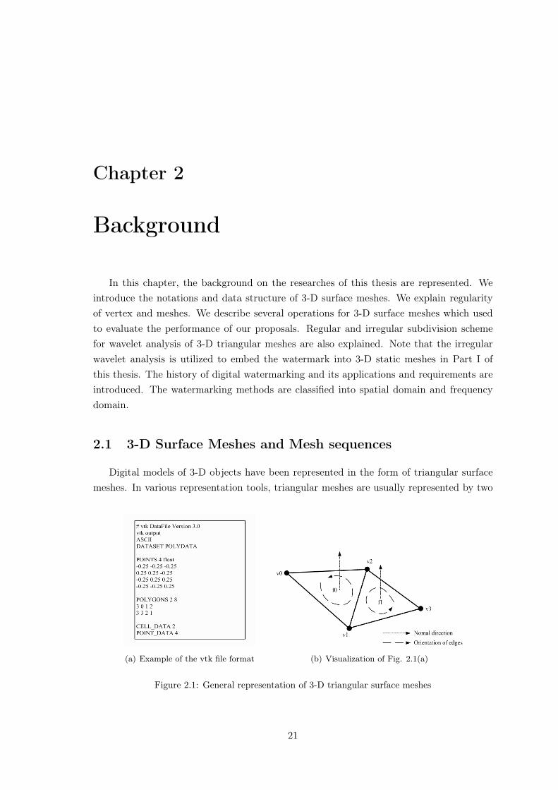
Digital models of 3-D objects have been represented in the form of triangular surfacemeshes. In various representation tools, triangular meshes are usually represented by two
(a) Example of the vtk file format (b) Visualization of Fig. 2.1(a)
Figure 2.1: General representation of 3-D triangular surface meshes
21
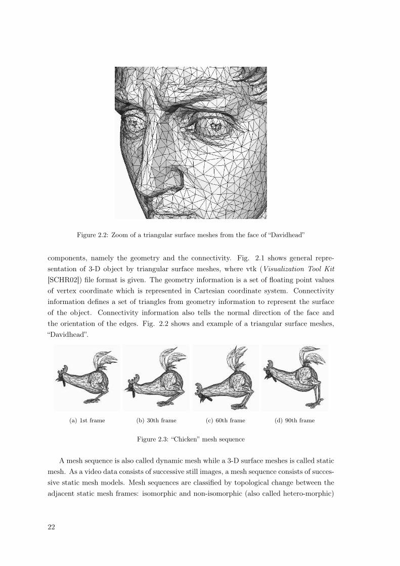
Figure 2.2: Zoom of a triangular surface meshes from the face of “Davidhead”
components, namely the geometry and the connectivity. Fig. 2.1 shows general repre-sentation of 3-D object by triangular surface meshes, where vtk (Visualization Tool Kit[SCHR02]) file format is given. The geometry information is a set of floating point valuesof vertex coordinate which is represented in Cartesian coordinate system. Connectivityinformation defines a set of triangles from geometry information to represent the surfaceof the object. Connectivity information also tells the normal direction of the face andthe orientation of the edges. Fig. 2.2 shows and example of a triangular surface meshes,“Davidhead”.
(a) 1st frame (b) 30th frame (c) 60th frame (d) 90th frame
Figure 2.3: “Chicken” mesh sequence
A mesh sequence is also called dynamic mesh while a 3-D surface meshes is called staticmesh. As a video data consists of successive still images, a mesh sequence consists of succes-sive static mesh models. Mesh sequences are classified by topological change between theadjacent static mesh frames: isomorphic and non-isomorphic (also called hetero-morphic)
22
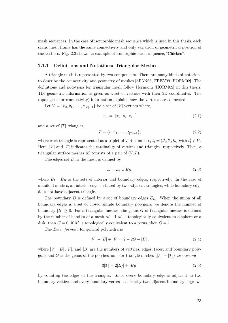
mesh sequences. In the case of isomorphic mesh sequence which is used in this thesis, eachstatic mesh frame has the same connectivity and only variation of geometrical position ofthe vertices. Fig. 2.3 shows an example of isomorphic mesh sequence, “Chicken”.
2.1.1 Definitions and Notations: Triangular Meshes
A triangle mesh is represented by two components. There are many kinds of notationsto describe the connectivity and geometry of meshes [SPAN66, FREY99, HORM02]. Thedefinitions and notations for triangular mesh follow Hormann [HORM02] in this thesis.The geometric information is given as a set of vertices with their 3D coordinates. Thetopological (or connectivity) information explains how the vertices are connected.
Let V = {v0, v1, · · · , v|V |−1} be a set of |V | vertices where,
vi = [xi yi zi ]t (2.1)
and a set of |T | triangles,T = {t0, t1, · · · , t|T |−1}, (2.2)
where each triangle is represented as a triplet of vertex indices, ti = (ti0, ti1, t
i2) with tik ∈ V .
Here, |V | and |T | indicates the cardinality of vertices and triangles, respectively. Then, atriangular surface meshes M consists of a pair of (V, T ).
The edges set E in the mesh is defined by
E = EI ∪ EB, (2.3)
where EI , EB is the sets of interior and boundary edges, respectively. In the case ofmanifold meshes, an interior edge is shared by two adjacent triangles, while boundary edgedoes not have adjacent triangle.
The boundary B is defined by a set of boundary edges EB. When the union of allboundary edges is a set of closed simple boundary polygons, we denote the number ofboundary |B| ≥ 0. For a triangular meshes, the genus G of triangular meshes is definedby the number of handles of a mesh M . If M is topologically equivalent to a sphere or adisk, then G = 0, if M is topologically equivalent to a torus, then G = 1.
The Euler formula for general polyhedra is
|V | − |E|+ |F | = 2− 2G− |B| , (2.4)
where |V | , |E| , |F |, and |B| are the numbers of vertices, edges, faces, and boundary poly-gons and G is the genus of the polyhedron. For triangle meshes (|F | = |T |) we observe
3|T | = 2|EI |+ |EB| (2.5)
by counting the edges of the triangles. Since every boundary edge is adjacent to twoboundary vertices and every boundary vertex has exactly two adjacent boundary edges we
23
further have|EB| = |VB| (2.6)
and rewrite Eq. 2.4 as
|V | − 12(|VB|+ |T |) = 2− 2G− |B| . (2.7)
2.1.2 Neighbor vertex and neighbor triangle
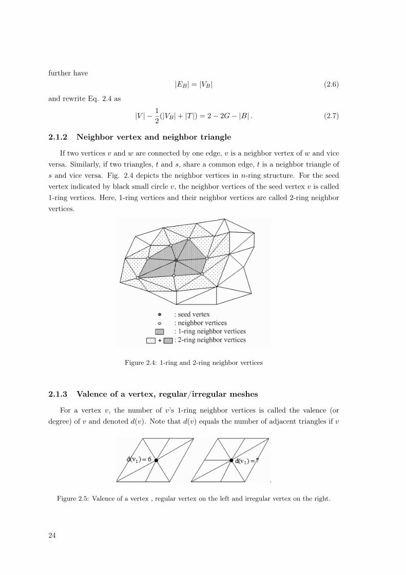
If two vertices v and w are connected by one edge, v is a neighbor vertex of w and viceversa. Similarly, if two triangles, t and s, share a common edge, t is a neighbor triangle ofs and vice versa. Fig. 2.4 depicts the neighbor vertices in n-ring structure. For the seedvertex indicated by black small circle v, the neighbor vertices of the seed vertex v is called1-ring vertices. Here, 1-ring vertices and their neighbor vertices are called 2-ring neighborvertices.
Figure 2.4: 1-ring and 2-ring neighbor vertices
2.1.3 Valence of a vertex, regular/irregular meshes
For a vertex v, the number of v’s 1-ring neighbor vertices is called the valence (ordegree) of v and denoted d(v). Note that d(v) equals the number of adjacent triangles if v
Figure 2.5: Valence of a vertex , regular vertex on the left and irregular vertex on the right.
24
(a) Regular meshes (b) Irregular meshes
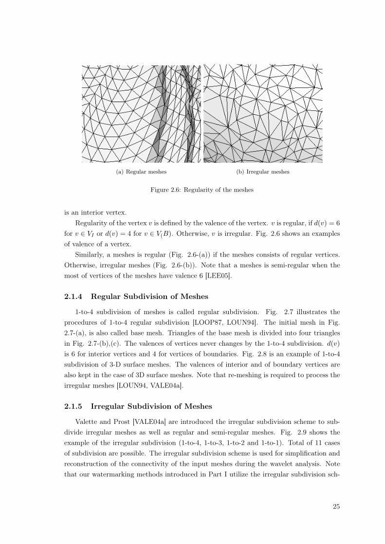
Figure 2.6: Regularity of the meshes
is an interior vertex.Regularity of the vertex v is defined by the valence of the vertex. v is regular, if d(v) = 6
for v ∈ VI or d(v) = 4 for v ∈ V(B). Otherwise, v is irregular. Fig. 2.6 shows an examplesof valence of a vertex.
Similarly, a meshes is regular (Fig. 2.6-(a)) if the meshes consists of regular vertices.Otherwise, irregular meshes (Fig. 2.6-(b)). Note that a meshes is semi-regular when themost of vertices of the meshes have valence 6 [LEE05].
2.1.4 Regular Subdivision of Meshes
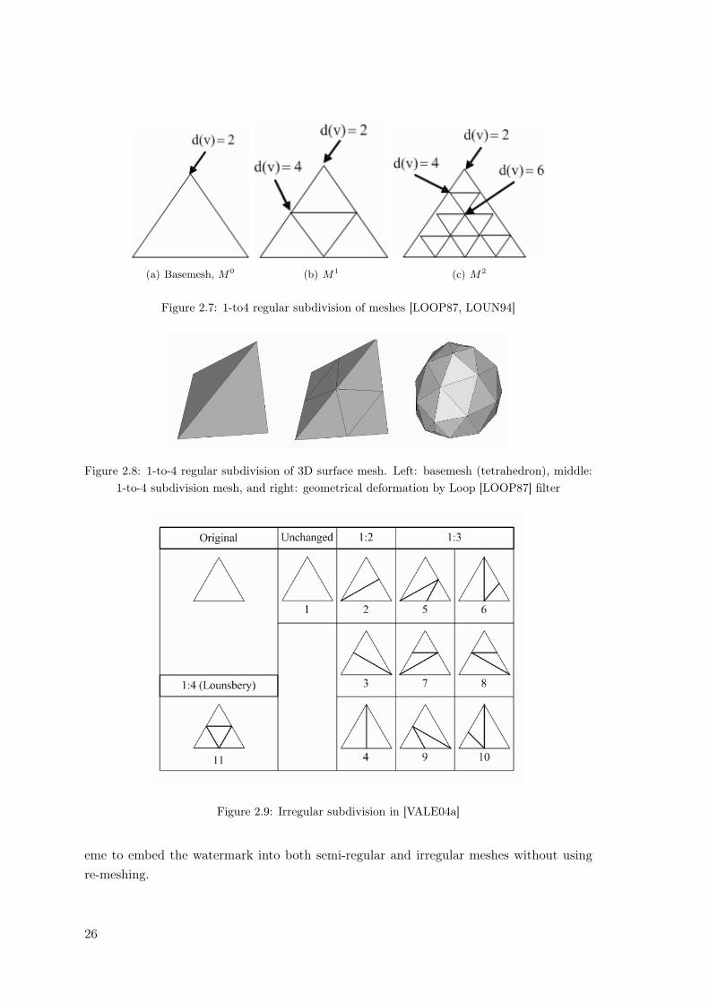
1-to-4 subdivision of meshes is called regular subdivision. Fig. 2.7 illustrates theprocedures of 1-to-4 regular subdivision [LOOP87, LOUN94]. The initial mesh in Fig.2.7-(a), is also called base mesh. Triangles of the base mesh is divided into four trianglesin Fig. 2.7-(b),(c). The valences of vertices never changes by the 1-to-4 subdivision. d(v)is 6 for interior vertices and 4 for vertices of boundaries. Fig. 2.8 is an example of 1-to-4subdivision of 3-D surface meshes. The valences of interior and of boundary vertices arealso kept in the case of 3D surface meshes. Note that re-meshing is required to process theirregular meshes [LOUN94, VALE04a].
2.1.5 Irregular Subdivision of Meshes
Valette and Prost [VALE04a] are introduced the irregular subdivision scheme to sub-divide irregular meshes as well as regular and semi-regular meshes. Fig. 2.9 shows theexample of the irregular subdivision (1-to-4, 1-to-3, 1-to-2 and 1-to-1). Total of 11 casesof subdivision are possible. The irregular subdivision scheme is used for simplification andreconstruction of the connectivity of the input meshes during the wavelet analysis. Notethat our watermarking methods introduced in Part I utilize the irregular subdivision sch-
25
(a) Basemesh, M0 (b) M1 (c) M2
Figure 2.7: 1-to4 regular subdivision of meshes [LOOP87, LOUN94]
Figure 2.8: 1-to-4 regular subdivision of 3D surface mesh. Left: basemesh (tetrahedron), middle:1-to-4 subdivision mesh, and right: geometrical deformation by Loop [LOOP87] filter
Figure 2.9: Irregular subdivision in [VALE04a]
eme to embed the watermark into both semi-regular and irregular meshes without usingre-meshing.
26
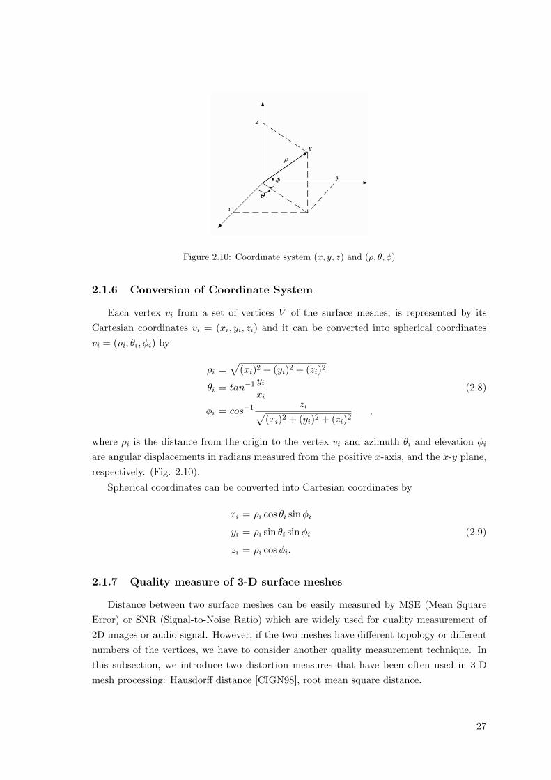
Figure 2.10: Coordinate system (x, y, z) and (ρ, θ, φ)
2.1.6 Conversion of Coordinate System
Each vertex vi from a set of vertices V of the surface meshes, is represented by itsCartesian coordinates vi = (xi, yi, zi) and it can be converted into spherical coordinatesvi = (ρi, θi, φi) by
ρi =√
(xi)2 + (yi)2 + (zi)2
θi = tan−1 yi
xi(2.8)
φi = cos−1 zi√(xi)2 + (yi)2 + (zi)2
,
where ρi is the distance from the origin to the vertex vi and azimuth θi and elevation φi
are angular displacements in radians measured from the positive x-axis, and the x-y plane,respectively. (Fig. 2.10).
Spherical coordinates can be converted into Cartesian coordinates by
xi = ρi cos θi sinφi
yi = ρi sin θi sinφi (2.9)
zi = ρi cosφi.
2.1.7 Quality measure of 3-D surface meshes
Distance between two surface meshes can be easily measured by MSE (Mean SquareError) or SNR (Signal-to-Noise Ratio) which are widely used for quality measurement of2D images or audio signal. However, if the two meshes have different topology or differentnumbers of the vertices, we have to consider another quality measurement technique. Inthis subsection, we introduce two distortion measures that have been often used in 3-Dmesh processing: Hausdorff distance [CIGN98], root mean square distance.
27
Hausdorff distance
Hausdorff distance is defined as a vertex-to-surface distance. Given a vertex v and aset of vertices V in a surface meshes, the distance is defined as,
e(v, V ) = minv′∈V
d(v, v′), (2.10)
where d(v, v′) is the euclidean distance between two points. The one-side distance betweentwo surfaces V and V ′ is then defined as,
E(V, V ′) = maxv∈V
e(v, V ′). (2.11)
Note that this definition of distance is not symmetric. There exist surface such thatE(V, V ′) 6= E(V ′, V ) [CIGN98, ASPE02]. A two-sided distance, so called Hausdorff dis-tance [CIGN98] is defined by taking the maximum of E(V, V ′) and E(V ′, V ).
EH(V, V ′) = max{E(V, V ′), E(V ′, V )}. (2.12)
Root Mean Square distance
Given a set of uniformly [ASPE02] or randomly [CIGN98] sampled mesh faces, wedefine the mean distance Emean between two surfaces as the surface integral of the distancedivided by the area of V :
Emean(V, V ′) =1
Area(V )
∫ ∫
Ve(v, V ′)dV v∈V (2.13)
From Eq. 2.10 and Eq. 2.13, a root mean square distance is defined as,
Erms(V, V ′) =
√1
Area(V )
∫
Ve(v, V ′)2dV v∈V (2.14)
Note that we utilize the maximum root mean square distance for the quality measure-ment of our watermarking methods throughout this thesis.
Emrms(V, V ′) = max{Erms(V, V ′), Erms(V ′, V )} (2.15)
28
2.2 Wavelet Analysis for 3-D Surface Meshes
Multiresolution analysis of 3-D object is receiving a lot of attention due to the practi-cal interest of 3-D modeling in a wider and wider range of applications, such as ComputerGraphics and Computer-Aided Design. Multiresolution analysis of these objects gives someuseful features: Several levels of detail can be built for these objects, accelerating the ren-dering when there is no need for sharp detail, and allowing progressive transmission. Wa-velet analysis, one of the most useful multiresolution representation techniques, have beenused in a broad range of applications, including image compression, physical simulation,hierarchical optimization, and numerical analysis. The basic idea behind wavelet analysisis to decompose a complicated function into a simpler coarse-resolution part, together witha collection of perturbations called wavelet coefficients. Lounsbery [LOUN94] extendedwavelet analysis to be applied to 3D surface meshes. In this subsection, we describe brieflythe wavelet analysis and some matters to be investigated for blind watermarking.
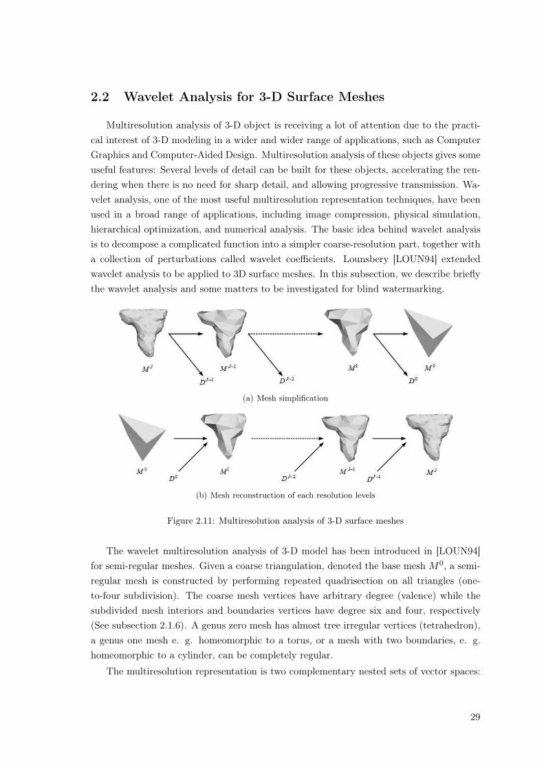
(a) Mesh simplification
(b) Mesh reconstruction of each resolution levels
Figure 2.11: Multiresolution analysis of 3-D surface meshes
The wavelet multiresolution analysis of 3-D model has been introduced in [LOUN94]for semi-regular meshes. Given a coarse triangulation, denoted the base mesh M0, a semi-regular mesh is constructed by performing repeated quadrisection on all triangles (one-to-four subdivision). The coarse mesh vertices have arbitrary degree (valence) while thesubdivided mesh interiors and boundaries vertices have degree six and four, respectively(See subsection 2.1.6). A genus zero mesh has almost tree irregular vertices (tetrahedron),a genus one mesh e. g. homeomorphic to a torus, or a mesh with two boundaries, e. g.homeomorphic to a cylinder, can be completely regular.
The multiresolution representation is two complementary nested sets of vector spaces:
29
the approximation spaces,
V 0 ⊂ V 1 ⊂ . . . ⊂ V J−1 ⊂ V J , (2.16)
and the detail spaces,W 0 ⊂ W 1 ⊂ . . . ⊂ W J−1, (2.17)
where V j = V j−1 ⊕W j−1. We denote by zero the coarsest space index and finer spaceshave higher index.
The multiresolution mesh set is a hierarchy of approximation
M0 ∈ V 0, M1 ∈ V 1 . . . V J ∈ MJ , (2.18)
where the highest level is that of the original mesh. Note that the highest level has noapproximation space. For the approximation vector space and the detail vector space thebasis function are the scaling function and the wavelets, respectively. As V j−1 and W j−1
are both subspaces of V j the scaling function in V j−1 and the wavelets in W j−1 are linearcombination of the scaling function in V j denoted by matrix P j and Qj , respectively. Inaddition V j = V j−1⊕W j−1, it follows that the approximation coefficients of the geometry(scaling coefficients) Cj (C =
[v0 v0 ˙ v|v|−1
]t) at the resolution j can be calculatedfrom the coarser approximation coefficient Cj−1 and detail coefficients (wavelet coefficients)Dj−1 by the synthesis formula,
Cj = P jCj−1 + QjDj−1. (2.19)
For the analysis, e. g. for the calculation of the approximation and detail coefficientsof M j at resolution j − 1, we remain that V j−1 ∈ V j and W j−1 ∈ V j the scaling functionin V j−1 and the wavelets in W j−1 are linear combination of the scaling function in V j
denoted by matrices Aj and Bj , respectively.
Cj−1 = AjCj (2.20)
Dj−1 = BjCj (2.21)
The matrices Aj , Bj , P j and Qj , define the analysis and reconstruction filter-bank,respectively. Note that sub-sampling is incorporated in the matrix operations. To ensurethe exact reconstruction of M j from M j−1 and Dj−1 , the filter-bank must satisfy:
[Aj
Bj
]=
[P j
∣∣Qj] −1 (2.22)
First, we only consider the Lounsbery scheme where the mesh as a 1:4 subdivisionconnectivity e.g. the mesh hierarchy can be considered as successive quadrisections ofthe base mesh (M0) faces followed by deformation of edges midpoints to fit the surfaceto be approximated. Conversely, four-to-one face coarsening is the inverse operation of
30
quadrisection. In this scheme the wavelets functions are hat functions associated with oddvertices of the mesh at resolution j and linearly vanishing on the opposite edges. Thiswavelet is often called the ”Lazy wavelet”. The scaling function are also hat function butwith a twice wider support and associated with the even vertices. Note that at the currentresolution j the Lazy wavelets are scaling functions at resolution j + 1.
Clearly the wavelet function basis is orthogonal but not that of the scaling function. Inaddition wavelets are not orthogonal to the scaling functions. It results a poor approxima-tion of the surface modeled by M j at level j − 1. The mesh M j−1 is just the sub-sampledmesh M j . Note that theses wavelets are used in the watermarking scheme [KANA98] and[UCCH04].
The Lazy wavelet can be improved by making it more orthogonal to the scaling functionby means of the Lifting scheme [SWEL95]. This is done by subtracting off some amount ofthe coarser scaling functions from each wavelet. This ’amount’ is introduced by coefficientsαj
i in the k-disc of the vertex of interest. The last step in calculated the new wavelet isto make it orthogonal to scaling function on the k-disc by solving an equation set in theleast-square sense for the unknown coefficients αj
i . It results a new (index lifting) filterbank as follows:
Aj = Ajlazy + αj .Bj
lazy (2.23)
Bj = Bjlazy (2.24)
P j = P jlazy (2.25)
Qj = Qjlazy − P j
lazy.αj (2.26)
Recently the wavelet multiresolution analysis has been extended to irregular mesh (ver-tices can have any degree) by Valette and Prost [VALE04a]. This new approach allowsdirect processing of the output mesh of isosurface extracted by usual algorithms such as thewell-known Marching Cubes [LORE87]. Due to the irregular connectivity of the connectiv-ity graph G the surface analysis by wavelets cannot be implemented without the knowledgeof face fusions needed for mesh coarsening. Coarsening is the inverse problem of successivesubdivision of the base mesh. In sharp contrast with Lounsbery regular 4 to 1 faces merge,in the irregular approach faces where merged 4:1, 3:1, 2:1, or 1:1 (no merge at the currentlevel). Fig. 2.9 shows an example of irregular subdivision. In addition edge flips whereused to improve the merging efficiency. In Wavemesh [VALE04a] face merge coarseningresults in the coding of the connectivity graph G with side information of edge flips. Themerging algorithm was based on region growing starting from a seed group of four facesmerged into one faces. In the particular cases of semi-regular mesh the seed group is chosenwith an irregular vertex on one of its corner in order to inverse the subdivision of the basemesh [VALE03]. After this first step the filter bank (Eq. 2.23-2.24) can be constructed andboth the approximation and detail coefficients can be computed from the highest level J tothe lowest level 0. Such stage takes into account of the merging factor and the connectivity
31
graph for both the matrix entries construction and the scalar product definitions used inthe lifting scheme. Similarly the reconstruction (synthesis) from level 0 to J results fromthe construction of the filter bank (Eq. 2.25-2.26) and filtering [VALE04a, VALE04b] ateach level. Note that the irregular wavelet analysis is applied to watermarking methodsfor 3-D surface meshes in Part I of this thesis.
2.3 Digital Watermarking
In this section, we explain the historical background of digital watermarking. Theapplications (copyright protection, ownership identification, certification, authentication,conditional access, copy-control, captioning and broadcast monitoring) and requirementsof digital watermarking are addressed. We classified the watermarking methods accordingto the type of watermark ( visible/invisible), the embedding domain(spatial/frequency do-main) and the detection method (blind/non-blind). We give a brief overview for watermarkembedding and extraction algorithms.
2.3.1 History
The idea of information hiding can be traced back to a few thousand years ago. Assurveyed in previous papers [PETI99, COX02], simply encrypted the content of messagesis not always suitable in practice. In many rivalry environments, concealing the existenceof communication is desirable to avoid suspicion from adversaries. Watermarking stemmedfrom the study of Steganography. The word “Steganography” originated from old Greeklanguage is still in use today. Steganography can be translated as “cover writing”. It wasbasically a way of transmitting secret messages between allies and was used as early as1000 BCE. First references to steganography appear in Homer’s “Iliad” and “Histories ofHerodotus” (440 BCE) [KEJA03, HERO03]. Demeratus sent a warning about a forthcom-ing attack to Greece by writing it on a wooden panel and covering it in wax. Wax tabletswere in common use then as re-usable writing surface, sometimes used for shorthand. An-other ancient example is that of Histiaeus [HIST], who shaved the head of his most trustedslave and tattooed a message on it. After his hair had grown the message was hidden.The purpose was to test a rebellion against the Persians. Digital watermarking takes itsname from watermarking of paper or money as a security measure. Watermarks first in-troduced in Bologna, Italy in 1282. They have been used by paper-makers to identify theirproduct, and also on postage stamps, currency, and other government documents to dis-courage counterfeiting. Digital watermarking is not a form of steganography, in which datais hidden in the message without the end user’s knowledge, although some watermarkingtechniques have the steganographic feature of not being perceivable by the human eye.While the addition of the hidden message to the signal does not restrict that signal’s use,it provides a mechanism to track the signal to the original owner. Tirkel et al. introduced
32
and defined the word “digital watermarking” and its related terminologies in [VANS94].
2.3.2 Application and Requirements
The first application of digital watermarking is related to copyright protection of dig-ital media. Digital watermark is designed to permanently reside in the host data withoutappending the header information, then the description about data can be embedded intothe data itself instead of using the metadata 1. Based on the idea of metadata, the water-marking technologies are available in ownership identification, for example, a real systemis implemented for International Science Information (ISI)’s Electronic Library Project[MINT97].
In the applications of data security, watermarks may be used for certification, authenti-cation, conditional access and copy-control. Digital watermarking allows to mutually linkinformation on the documents. For example, the name of a passport owner is normallyprinted in clear text and is hidden as an invisible watermark in the photo of the owner. Ifanyone would intend to forge the passport by replacing the photo, it is possible to noticethe forgery be scanning and detecting the watermark in the photo. Verification of au-thenticity of digital media may be done by fragile watermarking [FRID01, CAYR03]. Theobjective of verification includes the inspection of tampered area of the content. Condi-tional access or copy-control to confidential data on CD/DVD-ROMs is possible by usingthe digital watermark on the CD/DVD label which contains the key to decrypt data inCD/DVD [COX02]. The main idea is that someone has to scan and detect the watermarkon the label before accessing to confidential data in CD/DVD. If someone copy CD/DVD,he will not be able to read the clear-text in CD/DVD since he does not have the requiredwatermark.
‘The invisible information within data itself’ is very attractive characteristic of thedigital watermark in various application as well as copyright protection. The captioning ofthe digital media together with associated information could be easily achievable with theinvisible watermark. A good example for captioning is songs played on the radio. Whenthe music owners and the radio stations, are interested in an accurate count of exactlywhat gets played on the air. If the radio station plays a song with inaudibly watermarkedinformation, it enables an automatic radio listener monitoring for both radio station andthe music owner. In addition, this is also an interesting application for the sponsors oftelevision and radio stations. The stations can use the watermark of their sponsors andthe watermark will be embedded into the advertisement. Both the stations and the sponsorscan detect the watermark to log automatically that have been played. This application isalso called broadcast monitoring.
1Structured, encoded data that describe characteristics of information-bearing entities to aid in theidentification, discovery, assessment, and management of the described entities.
33
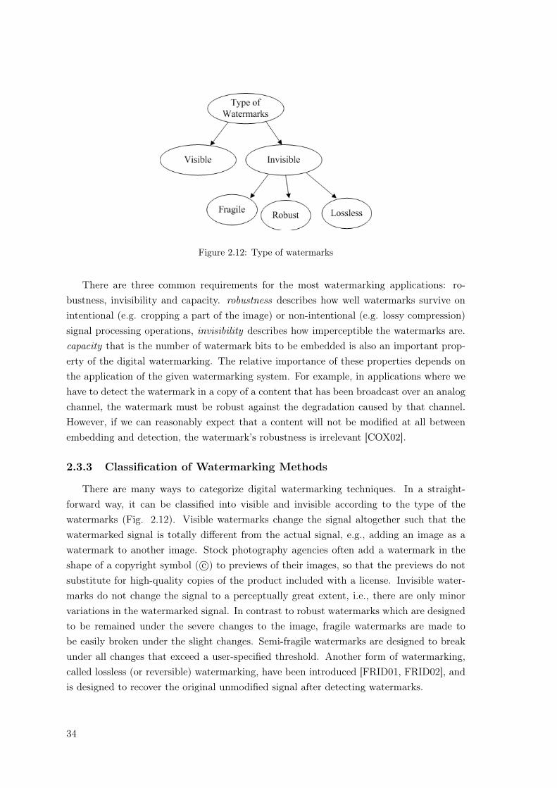
Figure 2.12: Type of watermarks
There are three common requirements for the most watermarking applications: ro-bustness, invisibility and capacity. robustness describes how well watermarks survive onintentional (e.g. cropping a part of the image) or non-intentional (e.g. lossy compression)signal processing operations, invisibility describes how imperceptible the watermarks are.capacity that is the number of watermark bits to be embedded is also an important prop-erty of the digital watermarking. The relative importance of these properties depends onthe application of the given watermarking system. For example, in applications where wehave to detect the watermark in a copy of a content that has been broadcast over an analogchannel, the watermark must be robust against the degradation caused by that channel.However, if we can reasonably expect that a content will not be modified at all betweenembedding and detection, the watermark’s robustness is irrelevant [COX02].
2.3.3 Classification of Watermarking Methods
There are many ways to categorize digital watermarking techniques. In a straight-forward way, it can be classified into visible and invisible according to the type of thewatermarks (Fig. 2.12). Visible watermarks change the signal altogether such that thewatermarked signal is totally different from the actual signal, e.g., adding an image as awatermark to another image. Stock photography agencies often add a watermark in theshape of a copyright symbol ( c©) to previews of their images, so that the previews do notsubstitute for high-quality copies of the product included with a license. Invisible water-marks do not change the signal to a perceptually great extent, i.e., there are only minorvariations in the watermarked signal. In contrast to robust watermarks which are designedto be remained under the severe changes to the image, fragile watermarks are made tobe easily broken under the slight changes. Semi-fragile watermarks are designed to breakunder all changes that exceed a user-specified threshold. Another form of watermarking,called lossless (or reversible) watermarking, have been introduced [FRID01, FRID02], andis designed to recover the original unmodified signal after detecting watermarks.
34
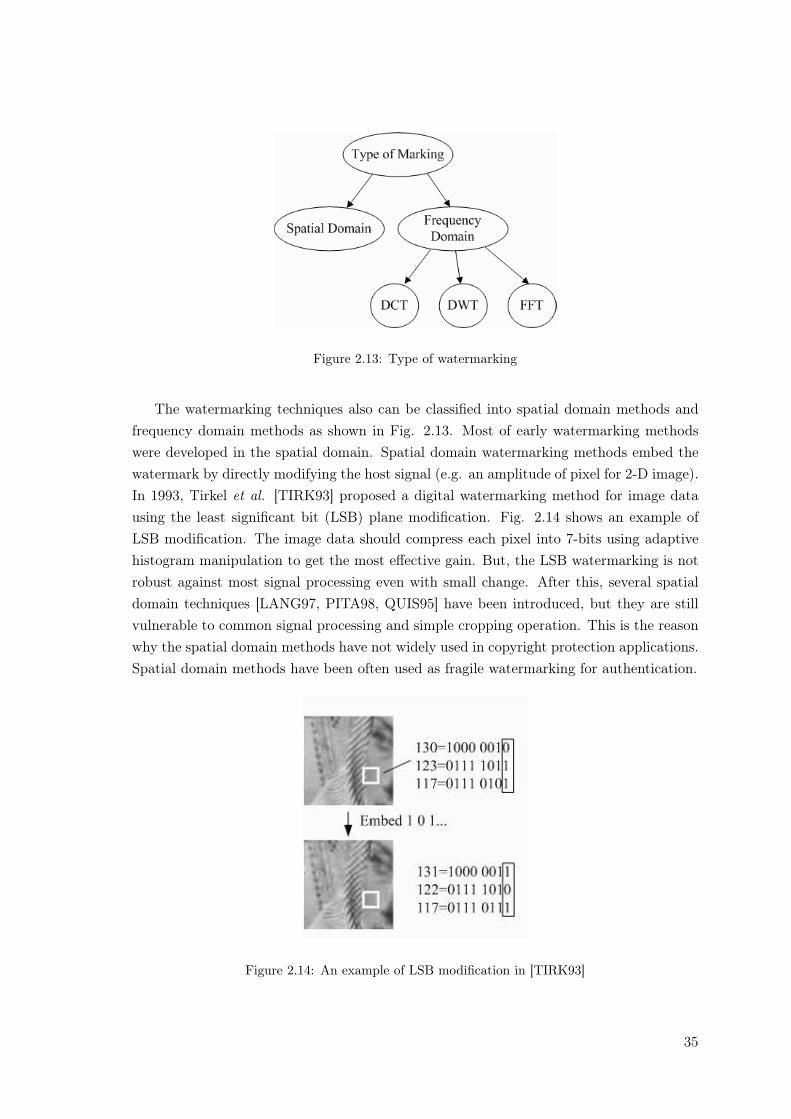
Figure 2.13: Type of watermarking
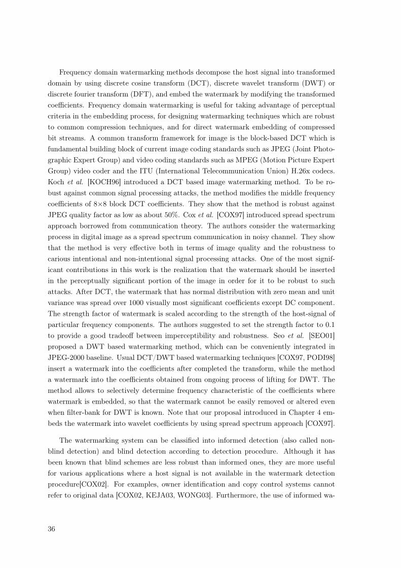
The watermarking techniques also can be classified into spatial domain methods andfrequency domain methods as shown in Fig. 2.13. Most of early watermarking methodswere developed in the spatial domain. Spatial domain watermarking methods embed thewatermark by directly modifying the host signal (e.g. an amplitude of pixel for 2-D image).In 1993, Tirkel et al. [TIRK93] proposed a digital watermarking method for image datausing the least significant bit (LSB) plane modification. Fig. 2.14 shows an example ofLSB modification. The image data should compress each pixel into 7-bits using adaptivehistogram manipulation to get the most effective gain. But, the LSB watermarking is notrobust against most signal processing even with small change. After this, several spatialdomain techniques [LANG97, PITA98, QUIS95] have been introduced, but they are stillvulnerable to common signal processing and simple cropping operation. This is the reasonwhy the spatial domain methods have not widely used in copyright protection applications.Spatial domain methods have been often used as fragile watermarking for authentication.
Figure 2.14: An example of LSB modification in [TIRK93]
35
Frequency domain watermarking methods decompose the host signal into transformeddomain by using discrete cosine transform (DCT), discrete wavelet transform (DWT) ordiscrete fourier transform (DFT), and embed the watermark by modifying the transformedcoefficients. Frequency domain watermarking is useful for taking advantage of perceptualcriteria in the embedding process, for designing watermarking techniques which are robustto common compression techniques, and for direct watermark embedding of compressedbit streams. A common transform framework for image is the block-based DCT which isfundamental building block of current image coding standards such as JPEG (Joint Photo-graphic Expert Group) and video coding standards such as MPEG (Motion Picture ExpertGroup) video coder and the ITU (International Telecommunication Union) H.26x codecs.Koch et al. [KOCH96] introduced a DCT based image watermarking method. To be ro-bust against common signal processing attacks, the method modifies the middle frequencycoefficients of 8×8 block DCT coefficients. They show that the method is robust againstJPEG quality factor as low as about 50%. Cox et al. [COX97] introduced spread spectrumapproach borrowed from communication theory. The authors consider the watermarkingprocess in digital image as a spread spectrum communication in noisy channel. They showthat the method is very effective both in terms of image quality and the robustness tocarious intentional and non-intentional signal processing attacks. One of the most signif-icant contributions in this work is the realization that the watermark should be insertedin the perceptually significant portion of the image in order for it to be robust to suchattacks. After DCT, the watermark that has normal distribution with zero mean and unitvariance was spread over 1000 visually most significant coefficients except DC component.The strength factor of watermark is scaled according to the strength of the host-signal ofparticular frequency components. The authors suggested to set the strength factor to 0.1to provide a good tradeoff between imperceptibility and robustness. Seo et al. [SEO01]proposed a DWT based watermarking method, which can be conveniently integrated inJPEG-2000 baseline. Usual DCT/DWT based watermarking techniques [COX97, PODI98]insert a watermark into the coefficients after completed the transform, while the methoda watermark into the coefficients obtained from ongoing process of lifting for DWT. Themethod allows to selectively determine frequency characteristic of the coefficients wherewatermark is embedded, so that the watermark cannot be easily removed or altered evenwhen filter-bank for DWT is known. Note that our proposal introduced in Chapter 4 em-beds the watermark into wavelet coefficients by using spread spectrum approach [COX97].
The watermarking system can be classified into informed detection (also called non-blind detection) and blind detection according to detection procedure. Although it hasbeen known that blind schemes are less robust than informed ones, they are more usefulfor various applications where a host signal is not available in the watermark detectionprocedure[COX02]. For examples, owner identification and copy control systems cannotrefer to original data [COX02, KEJA03, WONG03]. Furthermore, the use of informed wa-
36
termarking may cause to confuse the proof of ownership if an illegal user asserts that he/sheis the copyright holder with a corrupt watermarked data as his/her original [CRAV97].
2.4 Several operations for 3-D Surface Meshes
In this subsection, we address several operations to manipulate the 3D surface meshes.Since these operations can be used to interfere with the watermark extraction, they arealso called Attacks in the filed of digital watermarking. We categorize possible attacks onthe watermarked 3D surface meshes by two groups: geometrical attacks and topologicalattacks.
2.4.1 Geometrical Attacks
Geometrical attacks only changes the location of the vertices of the meshes. Addi-tive noise, uniform coordinate quantization, smoothing and RST (rotation, scaling andtranslation) attacks are considered as geometerical attacks.
Noise
The noise attack is to add random vectors to vertices of the watermarked meshes. Thisis one of the classical attacks in digital watermarking. Noise can be considered as one ofthe fashion to modelize geometry compression [CAYR03].
Smoothing
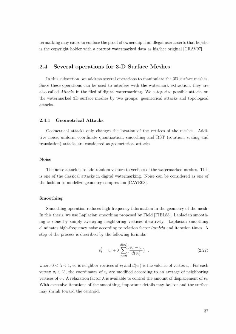
Smoothing operation reduces high frequency information in the geometry of the mesh.In this thesis, we use Laplacian smoothing proposed by Field [FIEL88]. Laplacian smooth-ing is done by simply averaging neighboring vertices iteratively. Laplacian smoothingeliminates high-frequency noise according to relation factor lambda and iteration times. Astep of the process is described by the following formula:
v′i = vi + λ
d(vi)∑
n=0
(vn − vi
d(vi)) , (2.27)
where 0 < λ < 1, vn is neighbor vertices of vi and d(vi) is the valence of vertex vi. For eachvertex vi ∈ V , the coordinates of vi are modified according to an average of neighboringvertices of vi. A relaxation factor λ is available to control the amount of displacement of vi.With excessive iterations of the smoothing, important details may be lost and the surfacemay shrink toward the centroid.
37
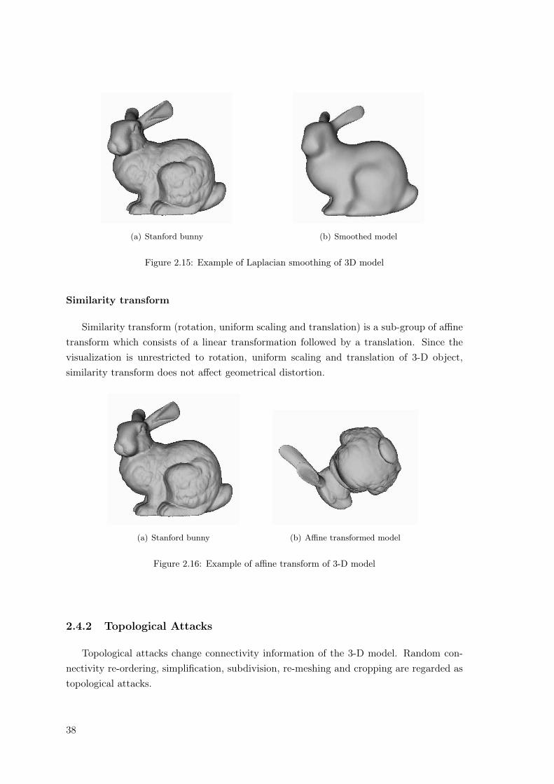
(a) Stanford bunny (b) Smoothed model
Figure 2.15: Example of Laplacian smoothing of 3D model
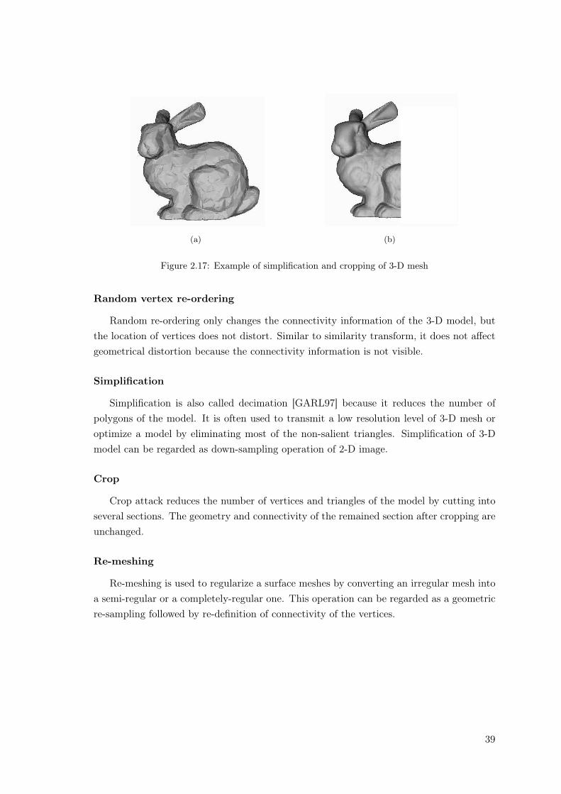
Similarity transform
Similarity transform (rotation, uniform scaling and translation) is a sub-group of affinetransform which consists of a linear transformation followed by a translation. Since thevisualization is unrestricted to rotation, uniform scaling and translation of 3-D object,similarity transform does not affect geometrical distortion.
(a) Stanford bunny (b) Affine transformed model
Figure 2.16: Example of affine transform of 3-D model
2.4.2 Topological Attacks
Topological attacks change connectivity information of the 3-D model. Random con-nectivity re-ordering, simplification, subdivision, re-meshing and cropping are regarded astopological attacks.
38
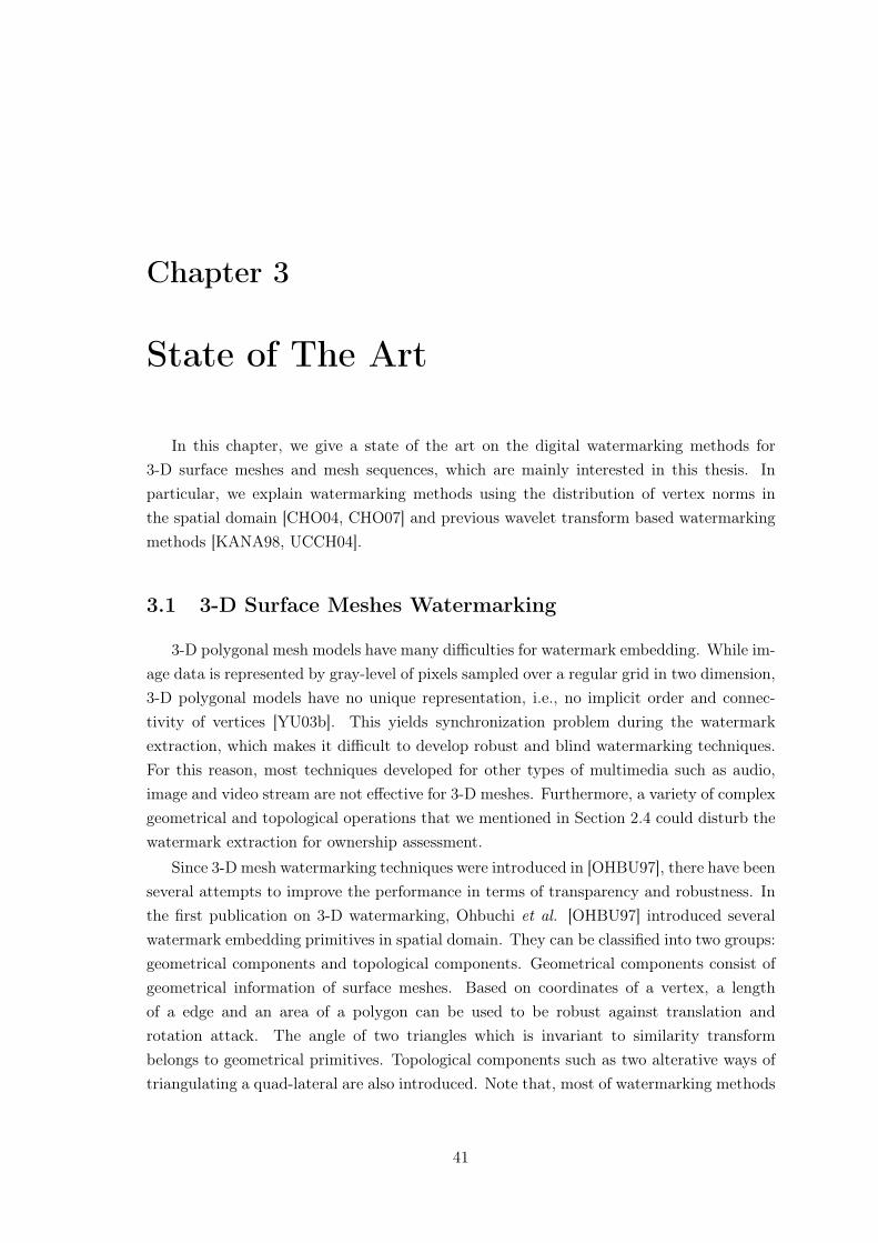
(a) (b)
Figure 2.17: Example of simplification and cropping of 3-D mesh
Random vertex re-ordering
Random re-ordering only changes the connectivity information of the 3-D model, butthe location of vertices does not distort. Similar to similarity transform, it does not affectgeometrical distortion because the connectivity information is not visible.
Simplification
Simplification is also called decimation [GARL97] because it reduces the number ofpolygons of the model. It is often used to transmit a low resolution level of 3-D mesh oroptimize a model by eliminating most of the non-salient triangles. Simplification of 3-Dmodel can be regarded as down-sampling operation of 2-D image.
Crop
Crop attack reduces the number of vertices and triangles of the model by cutting intoseveral sections. The geometry and connectivity of the remained section after cropping areunchanged.
Re-meshing
Re-meshing is used to regularize a surface meshes by converting an irregular mesh intoa semi-regular or a completely-regular one. This operation can be regarded as a geometricre-sampling followed by re-definition of connectivity of the vertices.
39

40
Chapter 3
State of The Art
In this chapter, we give a state of the art on the digital watermarking methods for3-D surface meshes and mesh sequences, which are mainly interested in this thesis. Inparticular, we explain watermarking methods using the distribution of vertex norms inthe spatial domain [CHO04, CHO07] and previous wavelet transform based watermarkingmethods [KANA98, UCCH04].
3.1 3-D Surface Meshes Watermarking
3-D polygonal mesh models have many difficulties for watermark embedding. While im-age data is represented by gray-level of pixels sampled over a regular grid in two dimension,3-D polygonal models have no unique representation, i.e., no implicit order and connec-tivity of vertices [YU03b]. This yields synchronization problem during the watermarkextraction, which makes it difficult to develop robust and blind watermarking techniques.For this reason, most techniques developed for other types of multimedia such as audio,image and video stream are not effective for 3-D meshes. Furthermore, a variety of complexgeometrical and topological operations that we mentioned in Section 2.4 could disturb thewatermark extraction for ownership assessment.
Since 3-D mesh watermarking techniques were introduced in [OHBU97], there have beenseveral attempts to improve the performance in terms of transparency and robustness. Inthe first publication on 3-D watermarking, Ohbuchi et al. [OHBU97] introduced severalwatermark embedding primitives in spatial domain. They can be classified into two groups:geometrical components and topological components. Geometrical components consist ofgeometrical information of surface meshes. Based on coordinates of a vertex, a lengthof a edge and an area of a polygon can be used to be robust against translation androtation attack. The angle of two triangles which is invariant to similarity transformbelongs to geometrical primitives. Topological components such as two alterative ways oftriangulating a quad-lateral are also introduced. Note that, most of watermarking methods
41
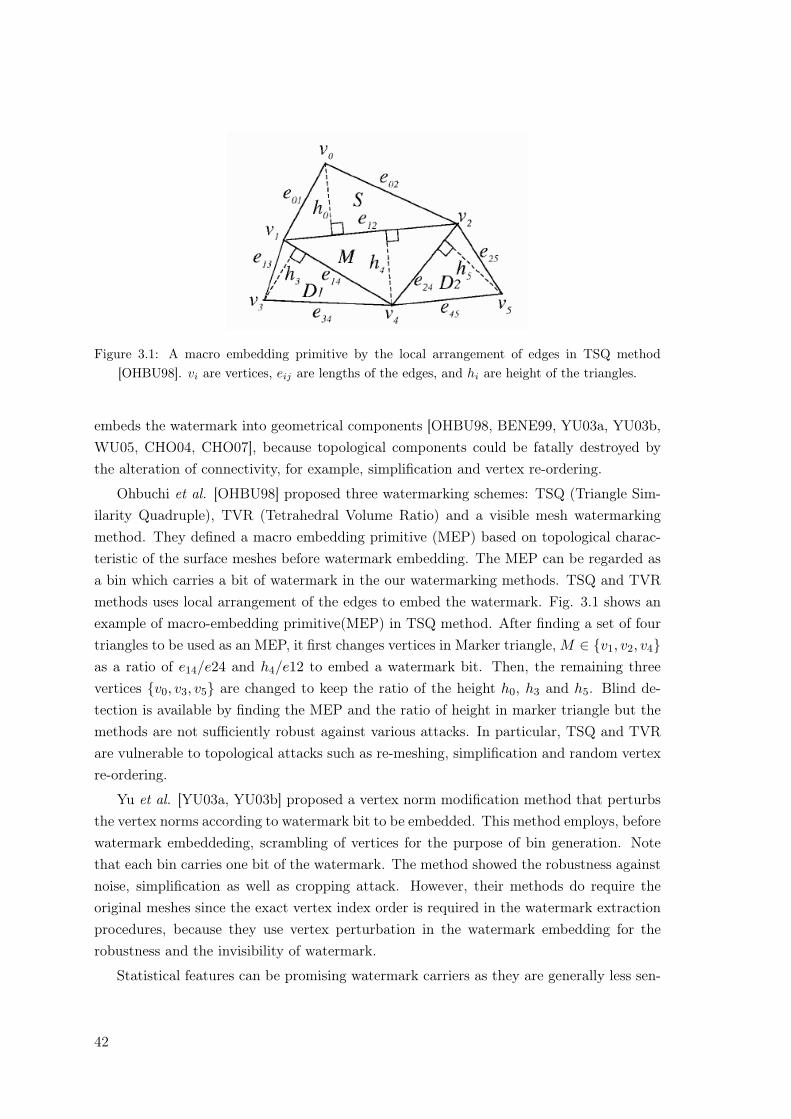
Figure 3.1: A macro embedding primitive by the local arrangement of edges in TSQ method[OHBU98]. vi are vertices, eij are lengths of the edges, and hi are height of the triangles.
embeds the watermark into geometrical components [OHBU98, BENE99, YU03a, YU03b,WU05, CHO04, CHO07], because topological components could be fatally destroyed bythe alteration of connectivity, for example, simplification and vertex re-ordering.
Ohbuchi et al. [OHBU98] proposed three watermarking schemes: TSQ (Triangle Sim-ilarity Quadruple), TVR (Tetrahedral Volume Ratio) and a visible mesh watermarkingmethod. They defined a macro embedding primitive (MEP) based on topological charac-teristic of the surface meshes before watermark embedding. The MEP can be regarded asa bin which carries a bit of watermark in the our watermarking methods. TSQ and TVRmethods uses local arrangement of the edges to embed the watermark. Fig. 3.1 shows anexample of macro-embedding primitive(MEP) in TSQ method. After finding a set of fourtriangles to be used as an MEP, it first changes vertices in Marker triangle, M ∈ {v1, v2, v4}as a ratio of e14/e24 and h4/e12 to embed a watermark bit. Then, the remaining threevertices {v0, v3, v5} are changed to keep the ratio of the height h0, h3 and h5. Blind de-tection is available by finding the MEP and the ratio of height in marker triangle but themethods are not sufficiently robust against various attacks. In particular, TSQ and TVRare vulnerable to topological attacks such as re-meshing, simplification and random vertexre-ordering.
Yu et al. [YU03a, YU03b] proposed a vertex norm modification method that perturbsthe vertex norms according to watermark bit to be embedded. This method employs, beforewatermark embeddeding, scrambling of vertices for the purpose of bin generation. Notethat each bin carries one bit of the watermark. The method showed the robustness againstnoise, simplification as well as cropping attack. However, their methods do require theoriginal meshes since the exact vertex index order is required in the watermark extractionprocedures, because they use vertex perturbation in the watermark embedding for therobustness and the invisibility of watermark.
Statistical features can be promising watermark carriers as they are generally less sen-
42
sitive to distortion-less attacks such as random vertex re-ordering and similarity transform[CHO07]. Several features can be obtained directly from 3-D meshes, particularly, thedistribution of vertex directions [BENE99] and that of vector norms [CHO04, CHO07].
Benedens [BENE99] proposed a watermark embedding method that modifies the localdistribution of vertex directions from the center of mass of model. As the distribution ofthe vertex direction is less sensitive to topological alteration, the method is robust againstsimplification attack. An extended scheme was also introduced in [LEE03] to overcomea weakness to cropping attack. In addition, although these methods [BENE99, LEE03]do not require the original mesh to extract the watermark, they require the radius ofvertices and the original center of mass as a side information for pre-processing. Notethat the distribution of the vertex directions essentially varies with the degree of rotation,therefore, the methods are not robust against rotation attack.
3.1.1 Blind Watermarking Methods Using the Distribution of VertexNorms
Distribution of vertex directions has been used as a watermark carrier [BENE99,LEE03], where vertices are grouped into distinct sets according to their local directionand the distribution of vertex direction is altered in each set separately. The distributiondoes not change by vertex re-ordering operation, but it varies in essence with rotationoperation. Thus, it requires re-orientation processing before watermark detection. Thedistribution of vertex norms does not change either by vertex re-ordering or rotation op-erations. In this subsection, we describe our previous works [CHO04, CHO07] which usethe distribution of vertex norms in . Note that our proposals introduced in Chapter 5 and6 use the distribution modification method.
Cho and Kim et al. [CHO04]
In our previous work of Cho and Kim et al. [CHO04], a blind watermarking scheme wasproposed. This method embeds the watermark information by modifying the distributionof vertex norms. Fig. 3.2 depicts the main idea behind the approach. Assume that vertexnorms have a uniform distribution in the range of [0, 1]. To embed a watermark bit of+1, the distribution is modified so that its mean value is greater than a reference value asshown in Fig. 3.2 (b). To embed −1, the distribution is modified so that it is concentratedon the left side, and the mean value becomes smaller than a reference as shown in Fig. 3.2(c).
To embed N bits of the watermark, all vertex norms are divided into N bins andnormalized into the rage of [0, 1]. Each bin is used as a unit to embed one bit of thewatermark bit. Fig. 3.3 shows the real distribution of a bunny model, which is dividedinto bins by dashed vertical lines. It also shows that the distribution of each bin is close to
43
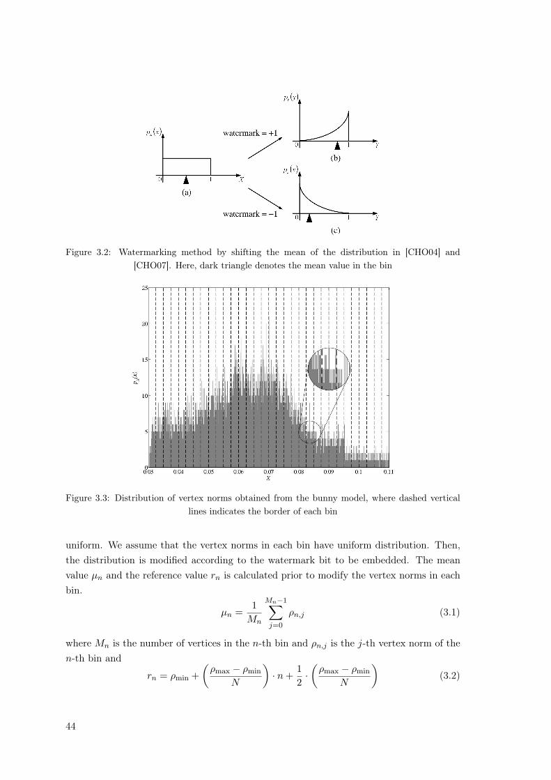
Figure 3.2: Watermarking method by shifting the mean of the distribution in [CHO04] and[CHO07]. Here, dark triangle denotes the mean value in the bin
Figure 3.3: Distribution of vertex norms obtained from the bunny model, where dashed verticallines indicates the border of each bin
uniform. We assume that the vertex norms in each bin have uniform distribution. Then,the distribution is modified according to the watermark bit to be embedded. The meanvalue µn and the reference value rn is calculated prior to modify the vertex norms in eachbin.
µn =1
Mn
Mn−1∑
j=0
ρn,j (3.1)
where Mn is the number of vertices in the n-th bin and ρn,j is the j-th vertex norm of then-th bin and
rn = ρmin +(
ρmax − ρmin
N
)· n +
12·(
ρmax − ρmin
N
)(3.2)
44
where ρmin and ρmax are the minimum and maximum vertex norm in the n-th bin, respec-tively.
To embed the n-th watermark bit, each vertex norm in the n-th bin is modified suchthat
ρ′n,j = ρn,j + αnωn (3.3)
where ωn is the watermark bit and αn is the strength factor of the watermark. αn isdetermined so as to guarantee such that µ′n > rn for ωn = +1 and µ′n < rn for ωn = −1,respectively.
αn > |rn − µn| if (ωn = +1 and µn < rn) or (ωn = −1 and µn > rn)
αn = 0 , otherwise(3.4)
where µn′ is the new mean value modified by watermark embedding. All vertex norms
in each bin are added by +αn or −αn. The relation between mean and reference valuesis preserved, when the processing is performed in separate bin by Eq. (3.4). Note thatαn needs to be carefully determined, because the modified vertex norms belong to certainbin could place into other neighbor bins. This artifact could affect the invisibility and therobustness of the watermark [CHO07].
Watermark detection process is quite simple, as the hidden watermark bit can be easilyextracted by comparing the mean value of vertex norms and a reference value.
ω′′n =
{+1, if µ′n > r′n−1, if µ′n < r′n
(3.5)
Although the watermark extraction in the case of cropping attack needs the originalcenter of gravity like in [BENE99], the watermark extraction does not require the originalmesh in the most of geometrical and topological attacks such as noise, vertex re-orderingand similarity transform [CHO04]. Note that the method can extract the error-free water-mark in the case of random vertex re-ordering and similarity transform.
Cho et al. [CHO07]
Cho et al. [CHO07] proposed two enhanced methods of their previous work [CHO04].The distribution of vertex norms are also used for the sake of the robustness against variousattacks and blind detection.
In this work, the distribution of vertex norms is modified by two methods. One is toshift the mean value of the vertex norms according to the watermark bit to be embeddedand another to change its variance. A similar approach has been used to shift the meanvalue in our previous work [CHO04], where a constant is added to vertex norms. Note thatmore sophisticated skills are introduced in this method. In particular, histogram mappingfunctions are newly introduced and used for the purpose of elaborate modification. Since
45
the statistical features are invariant to distortion-less attacks and less sensitive to variousdistortion ones with local geometric alterations, robustness of watermark can be easilyachieved. In addition, the proposed methods use the blind watermark detection scheme.
To embed N bits of the watermark, the probability distribution of vertex norms aredivided into N bins according to their magnitude. Each bin is normalized into the range of[0, 1]. Assume that each bin has a uniform distribution over the interval of [0, 1], then themean value of each bin is modified according to the watermark as shown in Fig. 3.2. Incontrast to additive watermark embedding in [CHO04], histogram mapping function wasproposed to shift the mean value. Histogram mapping functions can effectively modify thedistribution and reduce the visibility of the watermark as much as possible. The mappingfunction is given by
Y = Xk for 0 < k < ∞ and k ∈ < (3.6)
where X is a continuous random value with uniform distribution over the interval [0, 1], Y
is the transformed variable, and the parameter k is a real value for 0 < k < ∞. Clearly,the expectation of the random variable E [X] is given by
E [X] =∫ 1
0xpX (x) dx =
12
(3.7)
where pX (x) is the PDF (Probability Density Function) of X. This expectation E [X] isused as a reference value when moving the mean of each bin to a certain level. Vertexnorms in each bin are modified to shift the mean value. It is very important to assure thatthe modified vector norms also exist within the range of each bin. Otherwise, vector normsbelonging to a certain bin could shift into neighbor bins, which may have a serious impacton the watermark extraction [CHO04]. In [CHO07], histogram mapping function of Eq.(3.6) can shift the mean to the desired level through modifying the value of vector normswhile staying within the proper range.
Fig. 3.4 shows curves of the mapping function for different values of k. When theparameter k is selected in the range 1 < k < ∞, input variables are mapped into relativelysmall values. Moreover, increases in k decrease the value of the transformed variable. Itmeans the decrease of mean value. On other hand, the mean value increases for decreasingk when 0 < k < 1. Expectation of output random variable, E[Y ], is represented as;
E [Y ] = E[Xk
]=
∫ 1
0xkpX (x) dx =
1k + 1
. (3.8)
Fig. 3.5 shows the expectation of the output of the mapping function over k. Theexpectation value decreases monotonically with the parameter k. Therefore, we can easilyadjust the mean value of the distribution by selecting a proper parameter. In particular,the mapping function does not only guarantee to alter the variable within the limited range,but also allows shifting of the mean value to the desired level.
46
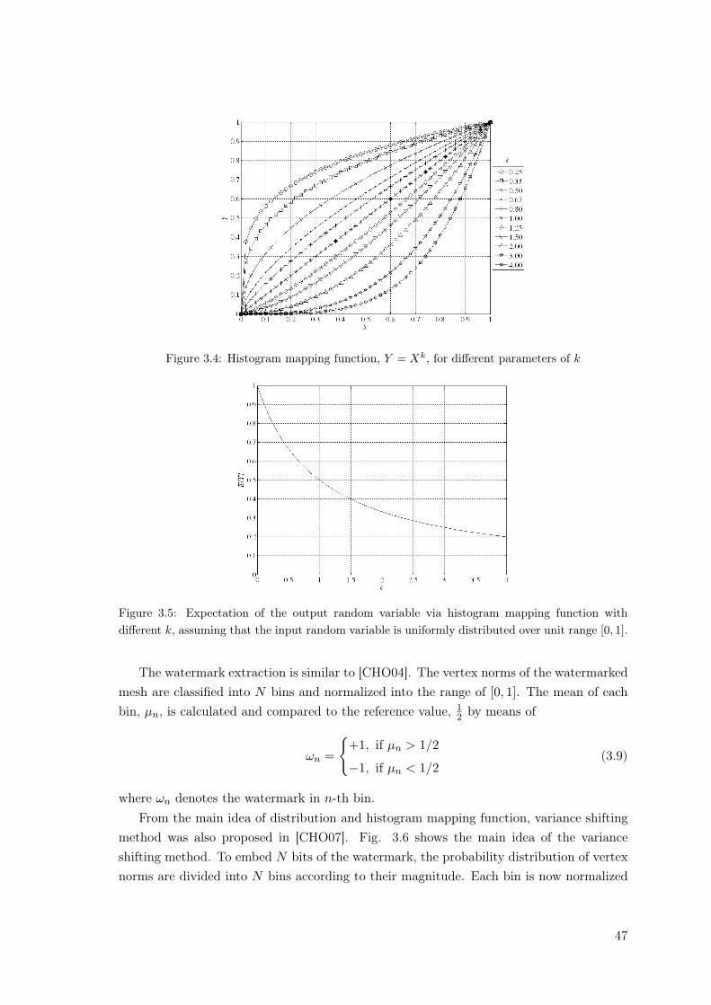
Figure 3.4: Histogram mapping function, Y = Xk, for different parameters of k
Figure 3.5: Expectation of the output random variable via histogram mapping function withdifferent k, assuming that the input random variable is uniformly distributed over unit range [0, 1].
The watermark extraction is similar to [CHO04]. The vertex norms of the watermarkedmesh are classified into N bins and normalized into the range of [0, 1]. The mean of eachbin, µn, is calculated and compared to the reference value, 1
2 by means of
ωn =
{+1, if µn > 1/2
−1, if µn < 1/2(3.9)
where ωn denotes the watermark in n-th bin.From the main idea of distribution and histogram mapping function, variance shifting
method was also proposed in [CHO07]. Fig. 3.6 shows the main idea of the varianceshifting method. To embed N bits of the watermark, the probability distribution of vertexnorms are divided into N bins according to their magnitude. Each bin is now normalized
47
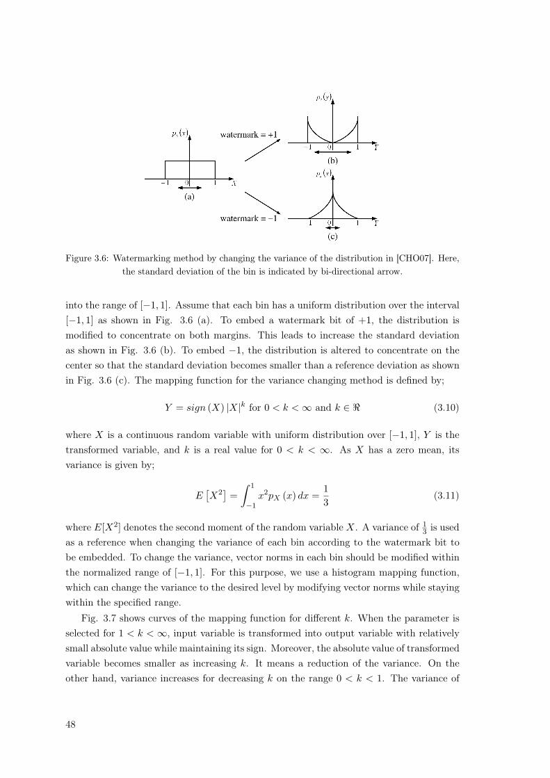
Figure 3.6: Watermarking method by changing the variance of the distribution in [CHO07]. Here,the standard deviation of the bin is indicated by bi-directional arrow.
into the range of [−1, 1]. Assume that each bin has a uniform distribution over the interval[−1, 1] as shown in Fig. 3.6 (a). To embed a watermark bit of +1, the distribution ismodified to concentrate on both margins. This leads to increase the standard deviationas shown in Fig. 3.6 (b). To embed −1, the distribution is altered to concentrate on thecenter so that the standard deviation becomes smaller than a reference deviation as shownin Fig. 3.6 (c). The mapping function for the variance changing method is defined by;
Y = sign (X) |X|k for 0 < k < ∞ and k ∈ < (3.10)
where X is a continuous random variable with uniform distribution over [−1, 1], Y is thetransformed variable, and k is a real value for 0 < k < ∞. As X has a zero mean, itsvariance is given by;
E[X2
]=
∫ 1
−1x2pX (x) dx =
13
(3.11)
where E[X2] denotes the second moment of the random variable X. A variance of 13 is used
as a reference when changing the variance of each bin according to the watermark bit tobe embedded. To change the variance, vector norms in each bin should be modified withinthe normalized range of [−1, 1]. For this purpose, we use a histogram mapping function,which can change the variance to the desired level by modifying vector norms while stayingwithin the specified range.
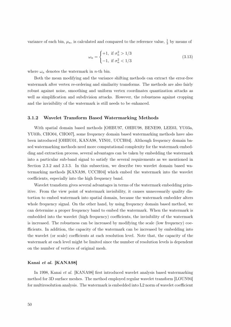
Fig. 3.7 shows curves of the mapping function for different k. When the parameter isselected for 1 < k < ∞, input variable is transformed into output variable with relativelysmall absolute value while maintaining its sign. Moreover, the absolute value of transformedvariable becomes smaller as increasing k. It means a reduction of the variance. On theother hand, variance increases for decreasing k on the range 0 < k < 1. The variance of
48
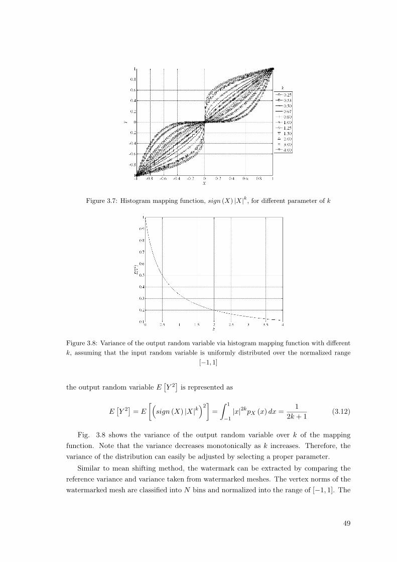
Figure 3.7: Histogram mapping function, sign (X) |X|k, for different parameter of k
Figure 3.8: Variance of the output random variable via histogram mapping function with differentk, assuming that the input random variable is uniformly distributed over the normalized range
[−1, 1]
the output random variable E[Y 2
]is represented as
E[Y 2
]= E
[(sign (X) |X|k
)2]
=∫ 1
−1|x|2kpX (x) dx =
12k + 1
(3.12)
Fig. 3.8 shows the variance of the output random variable over k of the mappingfunction. Note that the variance decreases monotonically as k increases. Therefore, thevariance of the distribution can easily be adjusted by selecting a proper parameter.
Similar to mean shifting method, the watermark can be extracted by comparing thereference variance and variance taken from watermarked meshes. The vertex norms of thewatermarked mesh are classified into N bins and normalized into the range of [−1, 1]. The
49
variance of each bin, µn, is calculated and compared to the reference value, 13 by means of
ωn =
{+1, if σ2
n > 1/3
−1, if σ2n < 1/3
(3.13)
where ωn denotes the watermark in n-th bin.
Both the mean modifying and the variance shifting methods can extract the error-freewatermark after vertex re-ordering and similarity transforms. The methods are also fairlyrobust against noise, smoothing and uniform vertex coordinates quantization attacks aswell as simplification and subdivision attacks. However, the robustness against croppingand the invisibility of the watermark is still needs to be enhanced.
3.1.2 Wavelet Transform Based Watermarking Methods
With spatial domain based methods [OHBU97, OHBU98, BENE99, LEE03, YU03a,YU03b, CHO04, CHO07], some frequency domain based watermarking methods have alsobeen introduced [OHBU01, KANA98, YIN01, UCCH04]. Although frequency domain ba-sed watermarking methods need more computational complexity for the watermark embed-ding and extraction process, several advantages can be taken by embedding the watermarkinto a particular sub-band signal to satisfy the several requirements as we mentioned inSection 2.3.2 and 2.3.3. In this subsection, we describe two wavelet domain based wa-termarking methods [KANA98, UCCH04] which embed the watermark into the waveletcoefficients, especially into the high frequency band.
Wavelet transform gives several advantages in terms of the watermark embedding prim-itive. From the view point of watermark invisibility, it causes unnecessarily quality dis-tortion to embed watermark into spatial domain, because the watermark embedder alterswhole frequency signal. On the other hand, by using frequency domain based method, wecan determine a proper frequency band to embed the watermark. When the watermark isembedded into the wavelet (high frequency) coefficients, the invisibility of the watermarkis increased. The robustness can be increased by modifying the scale (low frequency) coe-fficients. In addition, the capacity of the watermark can be increased by embedding intothe wavelet (or scale) coefficients at each resolution level. Note that, the capacity of thewatermark at each level might be limited since the number of resolution levels is dependenton the number of vertices of original mesh.
Kanai et al. [KANA98]
In 1998, Kanai et al. [KANA98] first introduced wavelet analysis based watermarkingmethod for 3D surface meshes. The method employed regular wavelet transform [LOUN94]for multiresolution analysis. The watermark is embedded into L2 norm of wavelet coefficient
50
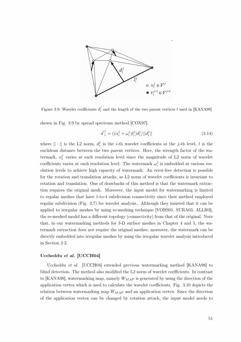
Figure 3.9: Wavelet coefficients dji and the length of the two parent vertices l used in [KANA98]
shown in Fig. 3.9 by spread spectrum method [COX97].
d′ji = ((αj
i + ωji )l
ji )d
ji/||dj
i || (3.14)
where || · || is the L2 norm, dji is the i-th wavelet coefficients at the j-th level, l is the
euclidean distance between the two parent vertices. Here, the strength factor of the wa-termark, αj
i varies at each resolution level since the magnitude of L2 norm of waveletcoefficients varies at each resolution level. The watermark ωj
i is embedded at various res-olution levels to achieve high capacity of watermark. An error-free detection is possiblefor the rotation and translation attacks, as L2 norm of wavelet coefficients is invariant torotation and translation. One of drawbacks of this method is that the watermark extrac-tion requires the original mesh. Moreover, the input model for watermarking is limitedto regular meshes that have 1-to-4 subdivision connectivity since their method employedregular subdivision (Fig. 2.7) for wavelet analysis,. Although they insisted that it can beapplied to irregular meshes by using re-meshing technique [VORS01, SURA03, ALLI03],the re-meshed model has a different topology (connectivity) from that of the original. Notethat, in our watermarking methods for 3-D surface meshes in Chapter 4 and 5, the wa-termark extraction does not require the original meshes, moreover, the watermark can bedirectly embedded into irregular meshes by using the irregular wavelet analysis introducedin Section 2.2.
Uccheddu et al. [UCCH04]
Uccheddu et al. [UCCH04] extended previous watermarking method [KANA98] toblind detection. The method also modified the L2 norm of wavelet coefficients. In contrastto [KANA98], watermarking map, namely WMAP is generated by using the direction of theapplication vertex which is used to calculate the wavelet coefficients. Fig. 3.10 depicts therelation between watermarking map WMAP and an application vertex. Since the directionof the application vertex can be changed by rotation attack, the input model needs to
51
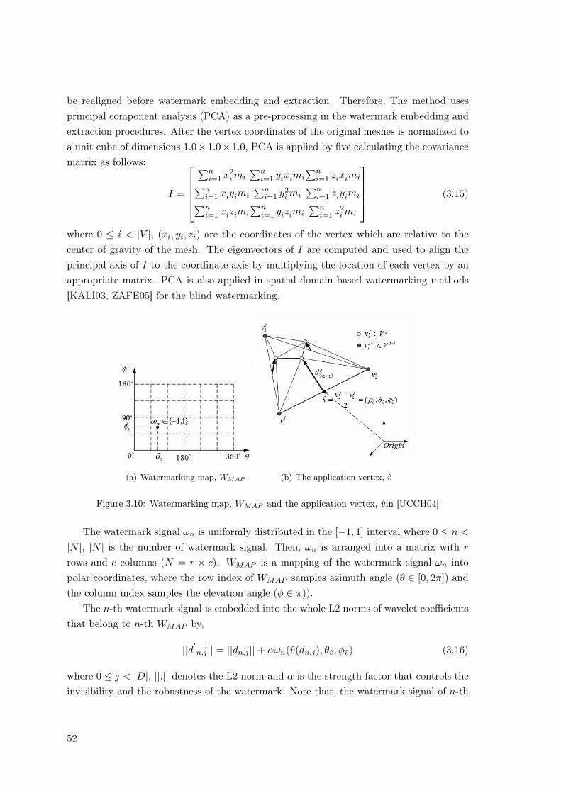
be realigned before watermark embedding and extraction. Therefore, The method usesprincipal component analysis (PCA) as a pre-processing in the watermark embedding andextraction procedures. After the vertex coordinates of the original meshes is normalized toa unit cube of dimensions 1.0× 1.0× 1.0, PCA is applied by five calculating the covariancematrix as follows:
I =
∑ni=1 x2
i mi∑n
i=1 yiximi∑n
i=1 ziximi∑n
i=1 xiyimi∑n
i=1 y2i mi
∑ni=1 ziyimi
∑ni=1 xizimi
∑ni=1 yizimi
∑ni=1 z2
i mi
(3.15)
where 0 ≤ i < |V |, (xi, yi, zi) are the coordinates of the vertex which are relative to thecenter of gravity of the mesh. The eigenvectors of I are computed and used to align theprincipal axis of I to the coordinate axis by multiplying the location of each vertex by anappropriate matrix. PCA is also applied in spatial domain based watermarking methods[KALI03, ZAFE05] for the blind watermarking.
(a) Watermarking map, WMAP (b) The application vertex, v
Figure 3.10: Watermarking map, WMAP and the application vertex, vin [UCCH04]
The watermark signal ωn is uniformly distributed in the [−1, 1] interval where 0 ≤ n <
|N |, |N | is the number of watermark signal. Then, ωn is arranged into a matrix with r
rows and c columns (N = r × c). WMAP is a mapping of the watermark signal ωn intopolar coordinates, where the row index of WMAP samples azimuth angle (θ ∈ [0, 2π]) andthe column index samples the elevation angle (φ ∈ π)).
The n-th watermark signal is embedded into the whole L2 norms of wavelet coefficientsthat belong to n-th WMAP by,
||d′n,j || = ||dn,j ||+ αωn(v(dn,j), θv, φv) (3.16)
where 0 ≤ j < |D|, ||.|| denotes the L2 norm and α is the strength factor that controls theinvisibility and the robustness of the watermark. Note that, the watermark signal of n-th
52
WMAP is determined by the direction of the application vertex v. Fig. 3.10-(b) depicts anapplication vertex v, where v(dv2,v1) = v2−v1
2 , v1 and v2 are two parent vertices to calculatethe wavelet coefficient, respectively.
Since the method embeds an 1-bit watermark, also called detectable watermark, thewatermark detector only tells the presence of the watermark. To detect the watermark,the wavelet coefficients are obtained from the watermarked meshes, and the correlationbetween the designed watermark signal and the whole wavelet coefficients in n-th WMAP
[COX97, COX02]. Similar extraction method based on the correlation is used in our methodin Chapter 4, but our method embed multi-bit watermark, also called readable watermark.
By using PCA before the watermark embedding and extraction procedure, the methodshowed fairly robustness against rotation and translation. One of the drawbacks of theapproach is that, the input mesh is still limited to regular meshes as is in [KANA98].The method is fairly robust against additive noise and smoothing. However, it might bevulnerable to topological attacks that cause a synchronization problem. The exact WMAP
by using the wavelet coefficients and the application vertex cannot be guaranteed aftertopology attacks. Note that, we explain the synchronization problem in Chapter 4 and 5.
3.2 3-D Mesh Sequence Watermarking
In this section, we address digital watermarking for 3-D mesh sequence. We also intro-duce temporal wavelet transform based watermarking methods for video data [SWAN98a]and motion data [KIMT00, YAMA04].
Unlike key-frame animation is used for real-time animation of 3-D medels in VRML(Virtual Reality Modeling Language) file format, mesh sequences are utilized to representrealistic visual data in many applications such as character animation in movies or videogames, cartoon, 3-D medical diagnosis, and so on. The enormous data size of 3-D meshsequence has brought many researches on its effective representation and the compression[LENG99, GUSK04, PAYA05, IBAR03, CHO06]. Although watermarking techniques havebeen developed for 3-D static meshes, there has been no watermarking methods for 3-Dmesh sequences based to our knowledge even though 3-D surface meshes models and 3-Dmesh sequence have already been commercially available. Obviously, 3-D mesh sequencesare also needed to be protected as copyrighted contents, as it is very time-consuming andhigh effort work to create or design such 3-D mesh sequences.
The watermarking for mesh sequences needs to consider the robustness against severalattacks as well as the invisibility and capacity of the watermark like in 3-D static meshwatermarking. For instance, several attacks in 3-D static meshes watermarking, namelyintra-frame attacks, are possible to each frame of the mesh sequence. 3-D mesh sequencewatermarking has another difficulty that generally do not have a counterpart in the wa-termarking of 3-D static meshes. Because of temporal redundancy of consecutive frames,
53
mesh sequence are exposed to inter-frame attacks, such as frame averaging, frame drop-ping, frame swapping and so on. These attacks may visually affect little or no damageto the sequence while the watermark in the sequence may be destroyed. Clearly, the wa-termarking of 3-D mesh sequence should consider the robustness against both intra-frameand inter-frame attacks.
For the robustness of the watermark, we propose 3-D mesh sequence watermarkingmethods based on the temporal wavelet transform. in Chapter 6. The temporal wavelettransform have often used in video watermarking methods [SWAN98a, KIM02, LIYI99].
In 1998, Swanson et al. [SWAN98a] introduced a watermarking method for copyrightprotection of video data based on temporal wavelet transform. Prior to embedding process,the original video sequence that would be watermarked was segmented into scenes andtemporal wavelet transform is applied to each scene, then a scene is decomposed intotemporal low frequency and high frequency frames. The watermark is embedded into8×8 DCT transformed coefficients of both low and high frequency frames. The correlationbetween the designed watermark signal and the watermarked video data is calculated for thewatermark detection. The method also showed the possibility of the watermark detectionfrom a single frame. This is a useful when we have no knowledge of the frame index of videosequence. The experimental results showed the robustness against various attacks such asadditive noise, MPEG video compression and frame dropping. Note that the methodembeds the detectable (1-bit) watermark and the correlation shows only the presence ofthe watermark similar to in [HART98, UCCH04]. 1-bit of the watermark is not sufficientto contain the information of the copy-right holder. It is evident that readable (multi-bit)watermark is more useful and required for the application of copy-right protection. Forinstance, Digital Cinema System [DCI, CIFE] specifies minimum 35 bits of capacity forevery 5 minutes to embed 16 bits of time stamp (time, date and year) and 19 bits of serialnumber to indicate location of the theater.
There have been two watermarking methods for the motion data for articulated com-puter graphics figures (e.g. the movement of joints in human body over the time) [KIMT00,YAMA04]. In general, the motion signal is obtained by motion capture devices and shouldbe associated with the 3-D model to be animated. In contrast to the data structureof mesh sequences, the motion data which is used in [KIMT00, YAMA04] consists ofthe angles of the joints, the marker positions, and the orientation of a body segment[YAMA04, KIMT00]. In their methods, the motion signal is decomposed into frequencydomain, and the watermark is embedded into the transformed coefficients of high (ormiddle) frequency domain by using spread-spectrum method [COX97]. The watermarkdetection requires the pre-processing such as registration and re-sampling using the ori-ginal motion signal. Note that these methods are only applicable to a special animationmethod which uses the motion signal.
54
Part I
Wavelet Analysis based DigitalWatermarking for 3-D Surface
Meshes
55

Chapter 4
Digital Watermarking Using WaveletCoefficient Norms
In this chapter, we introduce a digital watermarking method for 3-D surface meshesthat embeds the watermark into the wavelet coefficients. The proposed method is designedfor blind watermark detection, which can extract the watermark without reference of covermesh model. To ensure the connectivity synchronization after inverse wavelet transform,we introduced a vertex and face re-ordering process as pre-processing in both watermarkembedding and extraction. Since the wavelet coefficient norms is invariant to translationand rotations, the method is also robust against rotation and translation. This work haspublished in [KIM05].
4.1 Introduction
In the previous works, Kanai et al. [KANA98] proposed a watermarking method toembed the watermark into the wavelet coefficient vector in a certain order. The methodrequires the original mesh for the topological synchronization of the vertices. Uccheddu etal. [UCCH04] introduced a blind detection scheme by using the direction of applicationvertex, but this method embeds 1-bit of detectable watermark and it is just applicable to theinput meshes with regular subdivision connectivity as was in [KANA98]. In contrast withthe previous approaches [KANA98, UCCH04], as the irregular wavelet analysis [VALE04a]supports 1-to-4, 1-to-3, 1-to-2 and 1-to-1 subdivisions, our proposed method is directlyapplicable to both irregular and regular meshes.
57
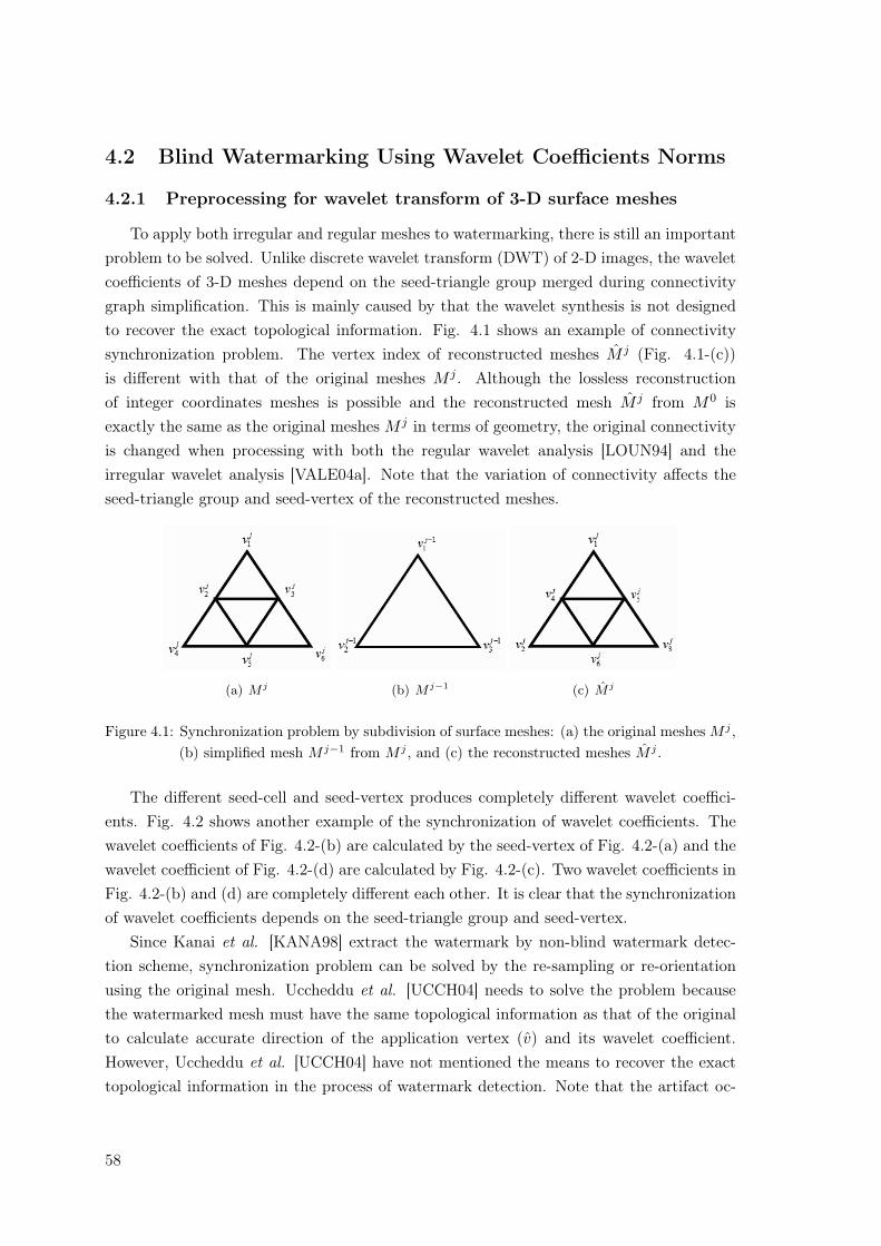
4.2 Blind Watermarking Using Wavelet Coefficients Norms
4.2.1 Preprocessing for wavelet transform of 3-D surface meshes
To apply both irregular and regular meshes to watermarking, there is still an importantproblem to be solved. Unlike discrete wavelet transform (DWT) of 2-D images, the waveletcoefficients of 3-D meshes depend on the seed-triangle group merged during connectivitygraph simplification. This is mainly caused by that the wavelet synthesis is not designedto recover the exact topological information. Fig. 4.1 shows an example of connectivitysynchronization problem. The vertex index of reconstructed meshes M j (Fig. 4.1-(c))is different with that of the original meshes M j . Although the lossless reconstructionof integer coordinates meshes is possible and the reconstructed mesh M j from M0 isexactly the same as the original meshes M j in terms of geometry, the original connectivityis changed when processing with both the regular wavelet analysis [LOUN94] and theirregular wavelet analysis [VALE04a]. Note that the variation of connectivity affects theseed-triangle group and seed-vertex of the reconstructed meshes.
(a) M j (b) M j−1 (c) M j
Figure 4.1: Synchronization problem by subdivision of surface meshes: (a) the original meshes M j ,(b) simplified mesh M j−1 from M j , and (c) the reconstructed meshes M j .
The different seed-cell and seed-vertex produces completely different wavelet coeffici-ents. Fig. 4.2 shows another example of the synchronization of wavelet coefficients. Thewavelet coefficients of Fig. 4.2-(b) are calculated by the seed-vertex of Fig. 4.2-(a) and thewavelet coefficient of Fig. 4.2-(d) are calculated by Fig. 4.2-(c). Two wavelet coefficients inFig. 4.2-(b) and (d) are completely different each other. It is clear that the synchronizationof wavelet coefficients depends on the seed-triangle group and seed-vertex.
Since Kanai et al. [KANA98] extract the watermark by non-blind watermark detec-tion scheme, synchronization problem can be solved by the re-sampling or re-orientationusing the original mesh. Uccheddu et al. [UCCH04] needs to solve the problem becausethe watermarked mesh must have the same topological information as that of the originalto calculate accurate direction of the application vertex (v) and its wavelet coefficient.However, Uccheddu et al. [UCCH04] have not mentioned the means to recover the exacttopological information in the process of watermark detection. Note that the artifact oc-
58
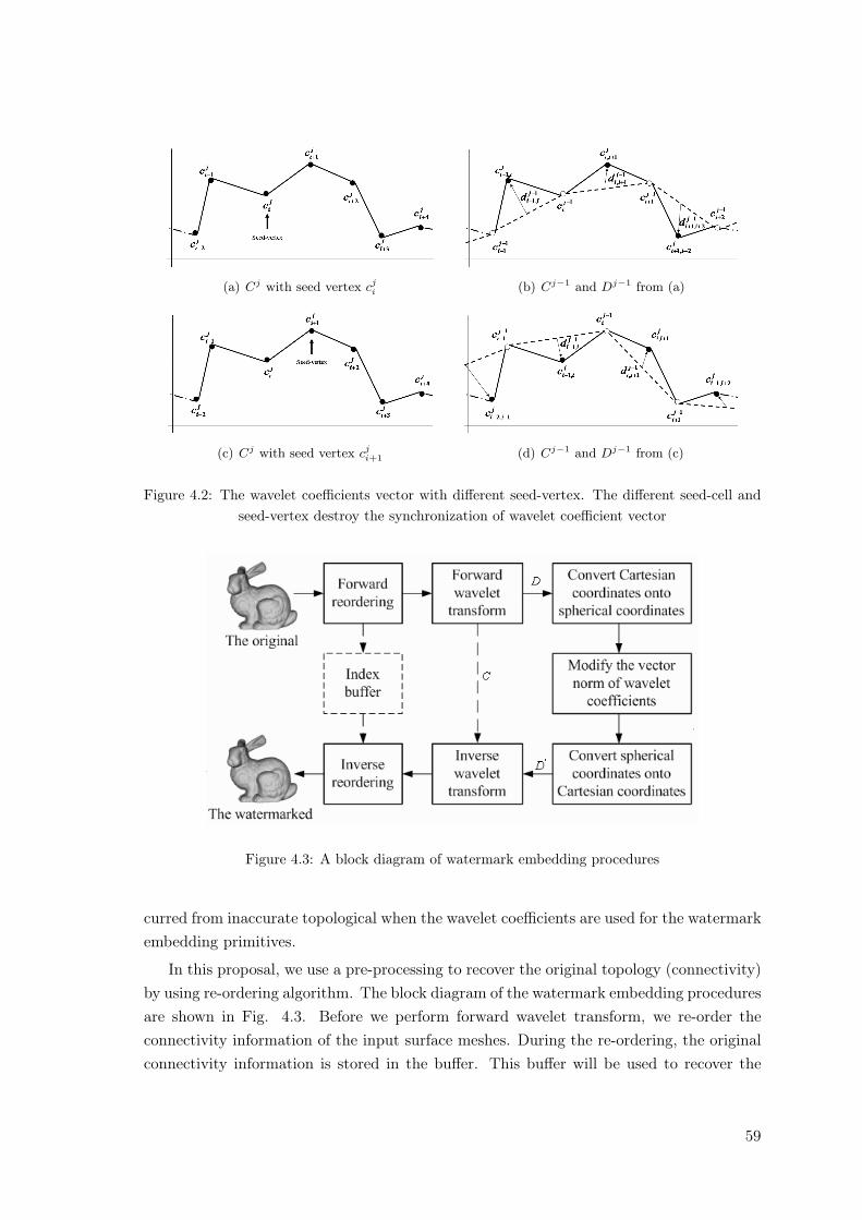
(a) Cj with seed vertex cji (b) Cj−1 and Dj−1 from (a)
(c) Cj with seed vertex cji+1 (d) Cj−1 and Dj−1 from (c)
Figure 4.2: The wavelet coefficients vector with different seed-vertex. The different seed-cell andseed-vertex destroy the synchronization of wavelet coefficient vector
Figure 4.3: A block diagram of watermark embedding procedures
curred from inaccurate topological when the wavelet coefficients are used for the watermarkembedding primitives.
In this proposal, we use a pre-processing to recover the original topology (connectivity)by using re-ordering algorithm. The block diagram of the watermark embedding proceduresare shown in Fig. 4.3. Before we perform forward wavelet transform, we re-order theconnectivity information of the input surface meshes. During the re-ordering, the originalconnectivity information is stored in the buffer. This buffer will be used to recover the
59
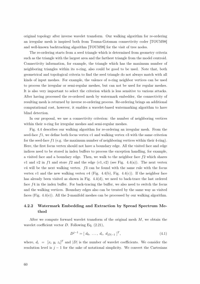
original topology after inverse wavelet transform. Our walking algorithm for re-orderingan irregular mesh is inspired both from Touma-Gotsman connectivity coder [TOUM98]and well-known backtracking algorithm [TOUM98] for the visit of tree nodes.
The re-ordering starts from a seed triangle which is determined from geometry criteriasuch as the triangle with the largest area and the farthest triangle from the model centroid.Connectivity information, for example, the triangle which has the maximum number ofneighboring triangles within its n-ring, also could be good to be used. Note that, bothgeometrical and topological criteria to find the seed triangle do not always match with allkinds of input meshes. For example, the valence of n-ring neighbor vertices can be usedto process the irregular or semi-regular meshes, but can not be used for regular meshes.It is also very important to select the criterion which is less sensitive to various attacks.After having processed the re-ordered mesh by watermark embedder, the connectivity ofresulting mesh is returned by inverse re-ordering process. Re-ordering brings an additionalcomputational cost, however, it enables a wavelet-based watermarking algorithm to haveblind detection.
In our proposal, we use a connectivity criterion: the number of neighboring verticeswithin their n-ring for irregular meshes and semi-regular meshes.
Fig. 4.4 describes our walking algorithm for re-ordering an irregular mesh. From theseed-face f1, we define both focus vertex v1 and walking vertex v3 with the same criterionfor the seed-face f1 (e.g. the maximum number of neighboring vertices within their 4-ring).Here, the first focus vertex should not have a boundary edge. All the visited face and edgeindices need to be stored in index buffers to process the exception handling, for example,a visited face and a boundary edge. Then, we walk to the neighbor face f2 which sharesv1 and v2 in f1 and store f2 and the edge (v1, v2) (see Fig. 4.4(a)). The next vertexv4 will be the next walking vertex. f3 can be found with the same rule with the focusvertex v1 and the new walking vertex v4 (Fig. 4.4(b), Fig. 4.4(c)). If the neighbor facehas already been visited as shown in Fig. 4.4(d), we need to back-trace the last orderedface f4 in the index buffer. For back-tracing the buffer, we also need to switch the focusand the walking vertices. Boundary edges also can be treated by the same way as visitedfaces (Fig. 4.4(e)). All the 2-manifold meshes can be processed by our walking algorithm.
4.2.2 Watermark Embedding and Extraction by Spread Spectrum Me-thod
After we compute forward wavelet transform of the original mesh M , we obtain thewavelet coefficient vector D. Following Eq. (2.21),
Dj−1 = [ d0, . . . , di, d|D|−1 ]T , (4.1)
where, di = [xi yi zi]T and |D| is the number of wavelet coefficients. We consider theresolution level is j − 1 for the sake of notational simplicity. We convert the Cartesians
60
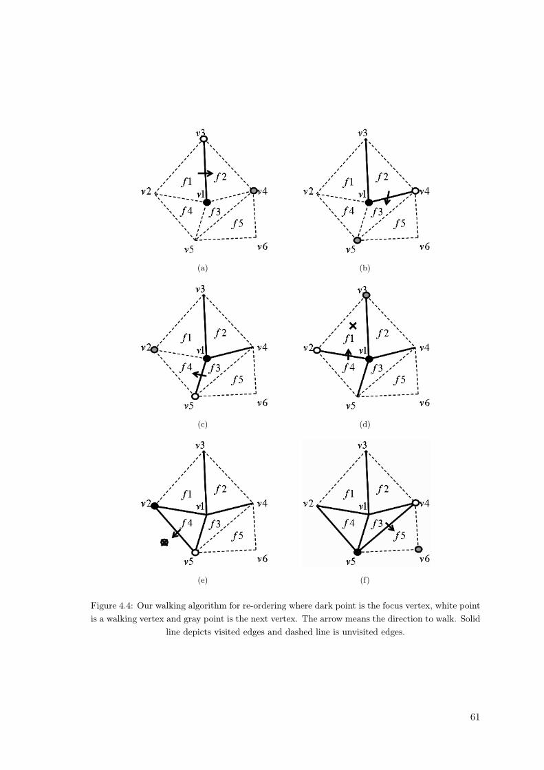
(a) (b)
(c) (d)
(e) (f)
Figure 4.4: Our walking algorithm for re-ordering where dark point is the focus vertex, white pointis a walking vertex and gray point is the next vertex. The arrow means the direction to walk. Solid
line depicts visited edges and dashed line is unvisited edges.
61
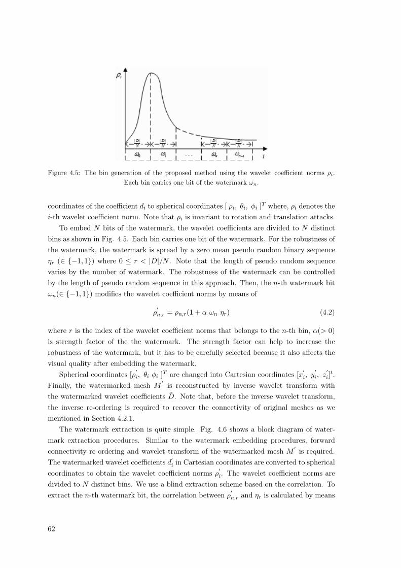
Figure 4.5: The bin generation of the proposed method using the wavelet coefficient norms ρi.Each bin carries one bit of the watermark ωn.
coordinates of the coefficient di to spherical coordinates [ ρi, θi, φi ]T where, ρi denotes thei-th wavelet coefficient norm. Note that ρi is invariant to rotation and translation attacks.
To embed N bits of the watermark, the wavelet coefficients are divided to N distinctbins as shown in Fig. 4.5. Each bin carries one bit of the watermark. For the robustness ofthe watermark, the watermark is spread by a zero mean pseudo random binary sequenceηr (∈ {−1, 1}) where 0 ≤ r < |D|/N . Note that the length of pseudo random sequencevaries by the number of watermark. The robustness of the watermark can be controlledby the length of pseudo random sequence in this approach. Then, the n-th watermark bitωn(∈ {−1, 1}) modifies the wavelet coefficient norms by means of
ρ′n,r = ρn,r(1 + α ωn ηr) (4.2)
where r is the index of the wavelet coefficient norms that belongs to the n-th bin, α(> 0)is strength factor of the the watermark. The strength factor can help to increase therobustness of the watermark, but it has to be carefully selected because it also affects thevisual quality after embedding the watermark.
Spherical coordinates [ρ′i, θi φi ]T are changed into Cartesian coordinates [x
′i, y
′i, z
′i]
t.Finally, the watermarked mesh M
′ is reconstructed by inverse wavelet transform withthe watermarked wavelet coefficients D. Note that, before the inverse wavelet transform,the inverse re-ordering is required to recover the connectivity of original meshes as wementioned in Section 4.2.1.
The watermark extraction is quite simple. Fig. 4.6 shows a block diagram of water-mark extraction procedures. Similar to the watermark embedding procedures, forwardconnectivity re-ordering and wavelet transform of the watermarked mesh M
′ is required.The watermarked wavelet coefficients d
′i in Cartesian coordinates are converted to spherical
coordinates to obtain the wavelet coefficient norms ρ′i. The wavelet coefficient norms are
divided to N distinct bins. We use a blind extraction scheme based on the correlation. Toextract the n-th watermark bit, the correlation between ρ
′n,r and ηr is calculated by means
62
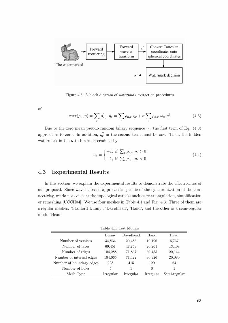
Figure 4.6: A block diagram of watermark extraction procedures
of
corr(ρ′n, η) =
∑r
ρ′n,r ηr =
∑r
ρn,r ηr + α∑
r
ρn,r ωn η2r (4.3)
Due to the zero mean pseudo random binary sequence ηr, the first term of Eq. (4.3)approaches to zero. In addition, η2
r in the second term must be one. Then, the hiddenwatermark in the n-th bin is determined by
ωn =
{+1, if
∑r ρ
′n,r ηr > 0
−1, if∑
r ρ′n,r ηr < 0
(4.4)
4.3 Experimental Results
In this section, we explain the experimental results to demonstrate the effectiveness ofour proposal. Since wavelet based approach is specific of the synchronization of the con-nectivity, we do not consider the topological attacks such as re-triangulation, simplificationor remeshing [UCCH04]. We use four meshes in Table 4.1 and Fig. 4.3. Three of them areirregular meshes: ‘Stanford Bunny’, ‘Davidhead’, ‘Hand’, and the other is a semi-regularmesh, ‘Head’.
Table 4.1: Test Models
Bunny Davidhead Hand HeadNumber of vertices 34,834 20,485 10,196 6,737Number of faces 69,451 47,753 20,261 13,408Number of edges 104,288 71,837 30,455 20,144
Number of internal edges 104,065 71,422 30,326 20,080Number of boundary edges 223 415 129 64
Number of holes 5 1 0 1Mesh Type Irregular Irregular Irregular Semi-regular
63
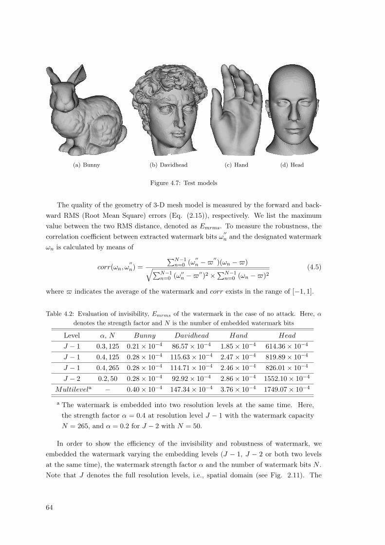
(a) Bunny (b) Davidhead (c) Hand (d) Head
Figure 4.7: Test models
The quality of the geometry of 3-D mesh model is measured by the forward and back-ward RMS (Root Mean Square) errors (Eq. (2.15)), respectively. We list the maximumvalue between the two RMS distance, denoted as Emrms. To measure the robustness, thecorrelation coefficient between extracted watermark bits ω
′′n and the designated watermark
ωn is calculated by means of
corr(ωn, ω′′n) =
∑N−1n=0 (ω
′′n −$
′′)(ωn −$)√∑N−1
n=0 (ω′′n −$′′)2 ×∑N−1n=0 (ωn −$)2
(4.5)
where $ indicates the average of the watermark and corr exists in the range of [−1, 1].
Table 4.2: Evaluation of invisibility, Emrms of the watermark in the case of no attack. Here, α
denotes the strength factor and N is the number of embedded watermark bits
Level α, N Bunny Davidhead Hand Head
J − 1 0.3, 125 0.21× 10⁻⁴ 86.57× 10⁻⁴ 1.85× 10⁻⁴ 614.36× 10⁻⁴
J − 1 0.4, 125 0.28× 10⁻⁴ 115.63× 10⁻⁴ 2.47× 10⁻⁴ 819.89× 10⁻⁴
J − 1 0.4, 265 0.28× 10⁻⁴ 114.71× 10⁻⁴ 2.46× 10⁻⁴ 826.01× 10⁻⁴
J − 2 0.2, 50 0.28× 10⁻⁴ 92.92× 10⁻⁴ 2.86× 10⁻⁴ 1552.10× 10−4
Multilevela − 0.40× 10⁻⁴ 147.34× 10⁻⁴ 3.76× 10⁻⁴ 1749.07× 10−4
a The watermark is embedded into two resolution levels at the same time. Here,the strength factor α = 0.4 at resolution level J − 1 with the watermark capacityN = 265, and α = 0.2 for J − 2 with N = 50.
In order to show the efficiency of the invisibility and robustness of watermark, weembedded the watermark varying the embedding levels (J − 1, J − 2 or both two levelsat the same time), the watermark strength factor α and the number of watermark bits N .Note that J denotes the full resolution levels, i.e., spatial domain (see Fig. 2.11). The
64
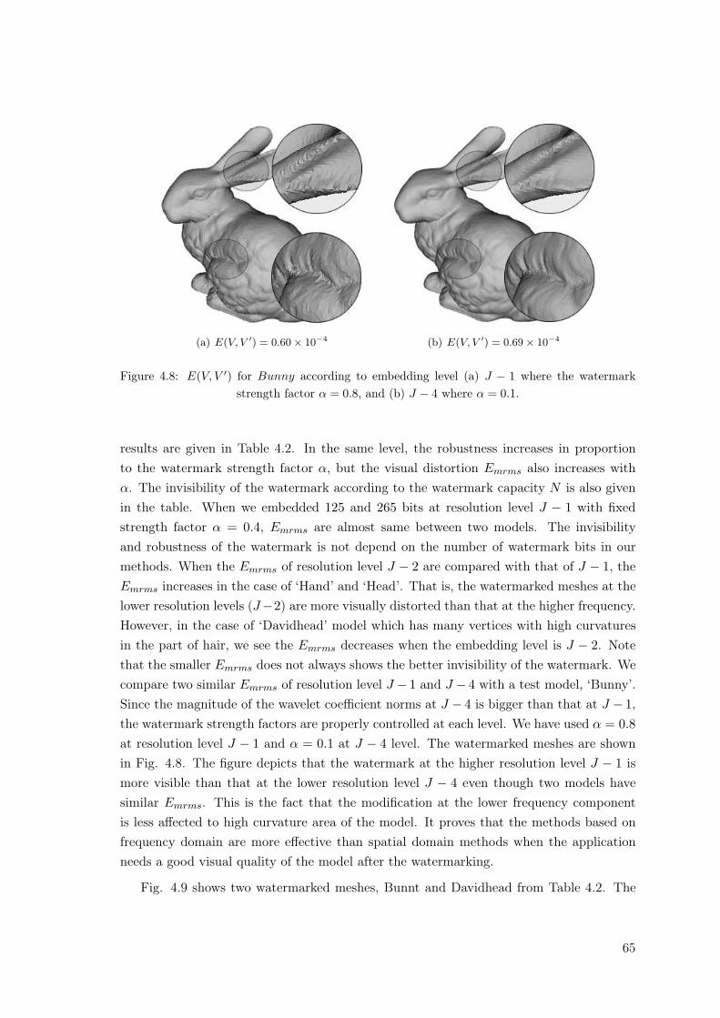
(a) E(V, V ′) = 0.60× 10⁻⁴ (b) E(V, V ′) = 0.69× 10⁻⁴
Figure 4.8: E(V, V ′) for Bunny according to embedding level (a) J − 1 where the watermarkstrength factor α = 0.8, and (b) J − 4 where α = 0.1.
results are given in Table 4.2. In the same level, the robustness increases in proportionto the watermark strength factor α, but the visual distortion Emrms also increases withα. The invisibility of the watermark according to the watermark capacity N is also givenin the table. When we embedded 125 and 265 bits at resolution level J − 1 with fixedstrength factor α = 0.4, Emrms are almost same between two models. The invisibilityand robustness of the watermark is not depend on the number of watermark bits in ourmethods. When the Emrms of resolution level J − 2 are compared with that of J − 1, theEmrms increases in the case of ‘Hand’ and ‘Head’. That is, the watermarked meshes at thelower resolution levels (J−2) are more visually distorted than that at the higher frequency.However, in the case of ‘Davidhead’ model which has many vertices with high curvaturesin the part of hair, we see the Emrms decreases when the embedding level is J − 2. Notethat the smaller Emrms does not always shows the better invisibility of the watermark. Wecompare two similar Emrms of resolution level J − 1 and J − 4 with a test model, ‘Bunny’.Since the magnitude of the wavelet coefficient norms at J − 4 is bigger than that at J − 1,the watermark strength factors are properly controlled at each level. We have used α = 0.8at resolution level J − 1 and α = 0.1 at J − 4 level. The watermarked meshes are shownin Fig. 4.8. The figure depicts that the watermark at the higher resolution level J − 1 ismore visible than that at the lower resolution level J − 4 even though two models havesimilar Emrms. This is the fact that the modification at the lower frequency componentis less affected to high curvature area of the model. It proves that the methods based onfrequency domain are more effective than spatial domain methods when the applicationneeds a good visual quality of the model after the watermarking.
Fig. 4.9 shows two watermarked meshes, Bunnt and Davidhead from Table 4.2. The
65
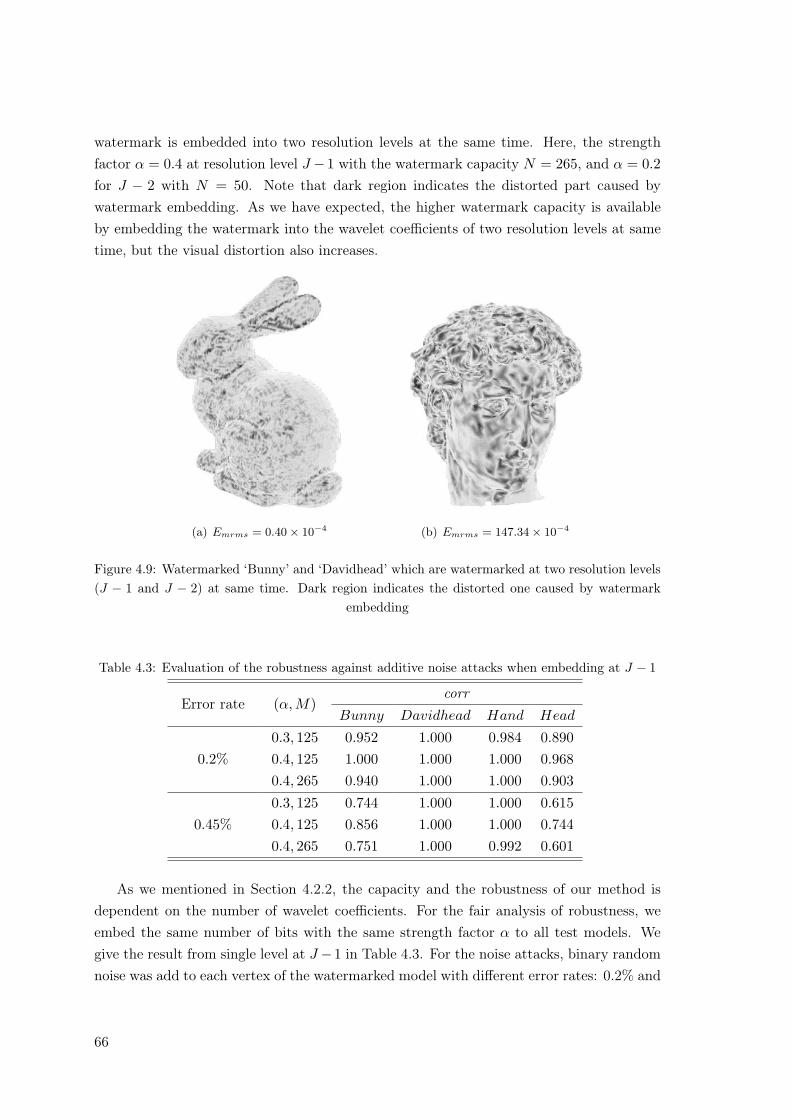
watermark is embedded into two resolution levels at the same time. Here, the strengthfactor α = 0.4 at resolution level J −1 with the watermark capacity N = 265, and α = 0.2for J − 2 with N = 50. Note that dark region indicates the distorted part caused bywatermark embedding. As we have expected, the higher watermark capacity is availableby embedding the watermark into the wavelet coefficients of two resolution levels at sametime, but the visual distortion also increases.
(a) Emrms = 0.40× 10⁻⁴ (b) Emrms = 147.34× 10⁻⁴
Figure 4.9: Watermarked ‘Bunny’ and ‘Davidhead’ which are watermarked at two resolution levels(J − 1 and J − 2) at same time. Dark region indicates the distorted one caused by watermark
embedding
Table 4.3: Evaluation of the robustness against additive noise attacks when embedding at J − 1
Error rate (α, M)corr
Bunny Davidhead Hand Head
0.2%0.3, 125 0.952 1.000 0.984 0.8900.4, 125 1.000 1.000 1.000 0.9680.4, 265 0.940 1.000 1.000 0.903
0.45%0.3, 125 0.744 1.000 1.000 0.6150.4, 125 0.856 1.000 1.000 0.7440.4, 265 0.751 1.000 0.992 0.601
As we mentioned in Section 4.2.2, the capacity and the robustness of our method isdependent on the number of wavelet coefficients. For the fair analysis of robustness, weembed the same number of bits with the same strength factor α to all test models. Wegive the result from single level at J −1 in Table 4.3. For the noise attacks, binary randomnoise was add to each vertex of the watermarked model with different error rates: 0.2% and
66
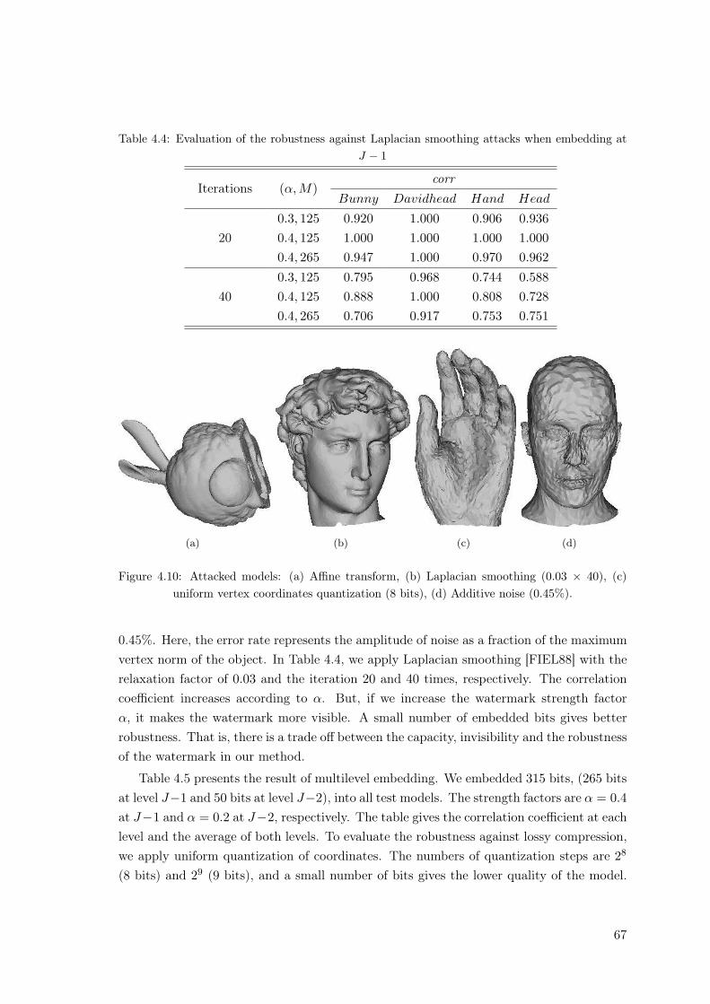
Table 4.4: Evaluation of the robustness against Laplacian smoothing attacks when embedding atJ − 1
Iterations (α, M)corr
Bunny Davidhead Hand Head
200.3, 125 0.920 1.000 0.906 0.9360.4, 125 1.000 1.000 1.000 1.0000.4, 265 0.947 1.000 0.970 0.962
400.3, 125 0.795 0.968 0.744 0.5880.4, 125 0.888 1.000 0.808 0.7280.4, 265 0.706 0.917 0.753 0.751
(a) (b) (c) (d)
Figure 4.10: Attacked models: (a) Affine transform, (b) Laplacian smoothing (0.03 × 40), (c)uniform vertex coordinates quantization (8 bits), (d) Additive noise (0.45%).
0.45%. Here, the error rate represents the amplitude of noise as a fraction of the maximumvertex norm of the object. In Table 4.4, we apply Laplacian smoothing [FIEL88] with therelaxation factor of 0.03 and the iteration 20 and 40 times, respectively. The correlationcoefficient increases according to α. But, if we increase the watermark strength factorα, it makes the watermark more visible. A small number of embedded bits gives betterrobustness. That is, there is a trade off between the capacity, invisibility and the robustnessof the watermark in our method.
Table 4.5 presents the result of multilevel embedding. We embedded 315 bits, (265 bitsat level J−1 and 50 bits at level J−2), into all test models. The strength factors are α = 0.4at J−1 and α = 0.2 at J−2, respectively. The table gives the correlation coefficient at eachlevel and the average of both levels. To evaluate the robustness against lossy compression,we apply uniform quantization of coordinates. The numbers of quantization steps are 28
(8 bits) and 29 (9 bits), and a small number of bits gives the lower quality of the model.
67
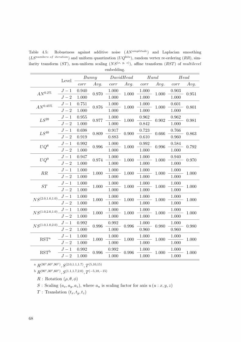
Table 4.5: Robustness against additive noise (ANamplitude) and Laplacian smoothing(LSnumbers of iteration) and uniform quantization (UQbits), random vertex re-ordering (RR), sim-ilarity transform (ST ), non-uniform scaling (NS(x, y, z)), affine transform (RST ) of multilevel
embedding.
LevelBunny DavidHead Hand Head
corr Avg. corr Avg. corr Avg. corr Avg.
AN0.2%J − 1 0.940
0.9701.000
1.0001.000
1.0000.903
0.951J − 2 1.000 1.000 1.000 1.000
AN0.45%J − 1 0.751
0.8761.000
1.0001.000
1.0000.601
0.801J − 2 1.000 1.000 1.000 1.000
LS20J − 1 0.955
0.9771.000
1.0000.962
0.9020.962
0.981J − 2 1.000 1.000 0.842 1.000
LS40J − 1 0.698
0.8090.917
0.9000.723
0.6660.766
0.863J − 2 0.919 0.883 0.610 0.960
UQ8J − 1 0.992
0.9961.000
1.0000.992
0.9960.584
0.792J − 2 1.000 1.000 1.000 1.000
UQ9J − 1 0.947
0.9741.000
1.0001.000
1.0000.940
0.970J − 2 1.000 1.000 1.000 1.000
RRJ − 1 1.000
1.0001.000
1.0001.000
1.0001.000
1.000J − 2 1.000 1.000 1.000 1.000
STJ − 1 1.000
1.0001.000
1.0001.000
1.0001.000
1.000J − 2 1.000 1.000 1.000 1.000
NS(2.0,1.0,1.0)J − 1 1.000
1.0001.000
1.0001.000
1.0001.000
1.000J − 2 1.000 1.000 1.000 1.000
NS(1.0,2.0,1.0)J − 1 1.000
1.0001.000
1.0001.000
1.0001.000
1.000J − 2 1.000 1.000 1.000 1.000
NS(1.0,1.0,2.0)J − 1 0.992
0.9960.992
0.9961.000
0.9801.000
0.980J − 2 1.000 1.000 0.960 0.960
RSTa J − 1 1.0001.000
1.0001.000
1.0001.000
1.0001.000
J − 2 1.000 1.000 1.000 1.000
RSTb J − 1 0.9920.996
0.9920.996
1.0001.000
1.0001.000
J − 2 1.000 1.000 1.000 1.000
a R(30◦,60◦,90◦), S(2.0,1.1,1.7), T (5,10,15)
b R(90◦,30◦,60◦), S(1.1,1.7,2.0), T (−5,10,−15)
R : Rotation (ρ, θ, φ)S : Scaling (ax, ay, az), where au is scaling factor for axis u (u : x, y, z)T : Translation (tx, ty, tz)
68
The resolution level J − 2 shows the better robustness than J − 1 because the waveletcoefficients DJ−2 are less affected than DJ−1 to the other attacks.
We also test similarity transform, affine transform, and random vertex re-ordering ofboth faces and vertex indices. Since the wavelet coefficient norms are invariant to rotationand translation, our method that embeds into wavelet coefficient norms gives error-freedetection on rotation and translation for both single level and multilevel. In addition, it isalso effective on scaling attacks including non-uniform scaling. Random re-ordering attackcan be recovered by the re-ordering before forward wavelet transform.
4.4 Conclusions
In this chapter, a watermarking method for 3-D surface meshes was proposed. Multire-solution wavelet analysis is used to achieve both the robustness and the invisibility of thewatermark. Since irregular wavelet analysis can be applied to both regular and irregularmeshes, our method do not use a pre-processing such as re-meshing for the watermarkembedding and extraction. To recover the topological information after inverse wavelettransform, vertex re-ordering algorithm was used as a pre-processing for forward wavelettransform and a post-processing for inverse wavelet transform. The watermarks which areembedded into the wavelet coefficients are visually imperceptible while having the goodrobustness against geometrical attacks and distortion-less attacks. Through the simula-tion results, we proved that the vertex and face re-ordering procedure as pre-processingfor both watermark embedding and extraction makes our method be robust against con-nectivity re-ordering attacks. We also showed that multiresolution embedding has morecapacity while keeping the robustness against connectivity re-ordering as well as geomet-rical attacks. However, the watermark which is embedded into the wavelet coefficients ina certain order can not be retrieved after topological attacks. For the robustness againsttopological attacks, pre-processing such as registration and re-sampling is required as in[PRAU99, YIN01], or the robustness against topological attacks cannot be guaranteed[KANA98, UCCH04, KIM05].
69

70
Chapter 5
Digital Watermarking MethodsUsing the Distribution of the ScaleCoefficients
In this chapter, we introduce a blind watermarking method for 3-D irregular surfacemeshes that embeds the watermark into the approximation meshes (scale coefficients ofthe wavelet transform). This work has published in [KIM06a, KIM06b].
5.1 Introduction
It is very important in general to determine a watermark carrier, also called primitive,that can effectively preserve watermark from attacks. For example, if the wavelet coeffi-cients or scale coefficients arranged in a certain order are used as the watermark carrier,the hidden watermark can not be retrieved without referring to the original model aftertopological attacks. This is caused by the fact that 3D polygonal meshes do not haveimplicit order and connectivity of vertices. For the same reason, pre-processing such asregistration and re-sampling is required as in [PRAU99, YIN01], or the robustness againsttopological attacks cannot be guaranteed [KANA98, UCCH04, KIM05]. In this chapter,we use statistical features of scale coefficients on approximated meshes as a watermarkcarrier. The statistical features might be less sensitive than the scale (or wavelet) coeffici-ents themselves in a certain order. The proposed methods modify the distribution of scalecoefficients to embed the watermark. It is not necessary to use any pre-processing such asregistration, re-sampling and re-ordering for wavelet analysis in the process of watermarkdetection. The hidden watermark is extracted, not only in the same resolution level asused in embedding process, but also in the spatial domain. Furthermore, the watermarkextraction in the spatial domain can reduce the computational complexity and process-ing time caused by wavelet transform. While these techniques may slightly decrease the
71
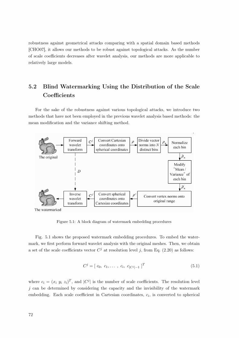
robustness against geometrical attacks comparing with a spatial domain based methods[CHO07], it allows our methods to be robust against topological attacks. As the numberof scale coefficients decreases after wavelet analysis, our methods are more applicable torelatively large models.
5.2 Blind Watermarking Using the Distribution of the ScaleCoefficients
For the sake of the robustness against various topological attacks, we introduce twomethods that have not been employed in the previous wavelet analysis based methods: themean modification and the variance shifting method.
Figure 5.1: A block diagram of watermark embedding procedures
Fig. 5.1 shows the proposed watermark embedding procedures. To embed the water-mark, we first perform forward wavelet analysis with the original meshes. Then, we obtaina set of the scale coefficients vector Cj at resolution level j, from Eq. (2.20) as follows:
Cj = [ c0, c1, . . . , ci, c|Cj |−1 ]T (5.1)
where ci = (xi yi zi)T , and |Cj | is the number of scale coefficients. The resolution levelj can be determined by considering the capacity and the invisibility of the watermarkembedding. Each scale coefficient in Cartesian coordinates, ci, is converted to spherical
72
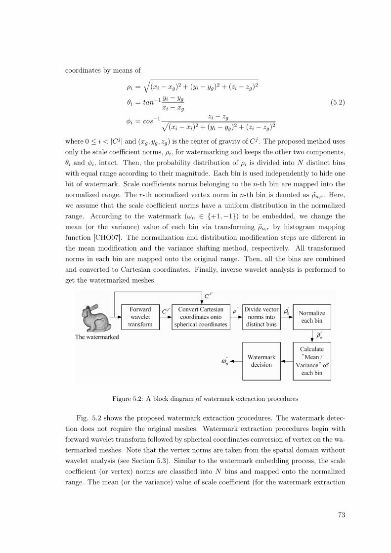
coordinates by means of
ρi =√
(xi − xg)2 + (yi − yg)2 + (zi − zg)2
θi = tan−1 yi − yg
xi − xg(5.2)
φi = cos−1 zi − zg√(xi − xi)2 + (yi − yg)2 + (zi − zg)2
where 0 ≤ i < |Cj | and (xg, yg, zg) is the center of gravity of Cj . The proposed method usesonly the scale coefficient norms, ρi, for watermarking and keeps the other two components,θi and φi, intact. Then, the probability distribution of ρi is divided into N distinct binswith equal range according to their magnitude. Each bin is used independently to hide onebit of watermark. Scale coefficients norms belonging to the n-th bin are mapped into thenormalized range. The r-th normalized vertex norm in n-th bin is denoted as ρn,r. Here,we assume that the scale coefficient norms have a uniform distribution in the normalizedrange. According to the watermark (ωn ∈ {+1,−1}) to be embedded, we change themean (or the variance) value of each bin via transforming ρn,r by histogram mappingfunction [CHO07]. The normalization and distribution modification steps are different inthe mean modification and the variance shifting method, respectively. All transformednorms in each bin are mapped onto the original range. Then, all the bins are combinedand converted to Cartesian coordinates. Finally, inverse wavelet analysis is performed toget the watermarked meshes.
Figure 5.2: A block diagram of watermark extraction procedures
Fig. 5.2 shows the proposed watermark extraction procedures. The watermark detec-tion does not require the original meshes. Watermark extraction procedures begin withforward wavelet transform followed by spherical coordinates conversion of vertex on the wa-termarked meshes. Note that the vertex norms are taken from the spatial domain withoutwavelet analysis (see Section 5.3). Similar to the watermark embedding process, the scalecoefficient (or vertex) norms are classified into N bins and mapped onto the normalizedrange. The mean (or the variance) value of scale coefficient (for the watermark extraction
73
in wavelet domain) or vertex norms (for the watermark extraction in spatial domain) arecalculated in each bin and compared to each reference value.
5.2.1 Mean Modification Method
This method embeds the watermark information by shifting the mean value of eachbin according to an assigned watermark bit. In this subsection, we describe mainly thenormalization and the mean modification steps in the watermark embedding procedureand watermark decision step in the extraction procedure.
In the normalization step, the scale coefficient norms, ρn,r, belonging to the n-th binare mapped into the normalized range of [0, 1] by
ρn,r =ρn,r −minρn,r
maxρn,r −minρn,r
(5.3)
where ρn,r is the r-th normalized norm of the n-th bin. maxρn,r is the maximum norm ofthe n-th bin and minρn,r is the minimum norm. We assume that each bin has a distributionvery close to uniform over the unit interval.
In the mean modification step, the mean of n-th bin, µn, is shifted by a factor +α (or−α) to embed n-th watermark bit ωn = +1 (or ωn = −1), as follows:
µ′n =
{12 + α if ωn = +112 − α if ωn = −1
(5.4)
where α (0 < α < 12) is the strength factor that can control the robustness, the transparency
of watermark, and mu′n is the modified mean value. To shift the mean to the desired level,
the normalized scale coefficient norms, ρn,r, are transformed iteratively by a histogrammapping function as follows:
ρ′n,r = (ρn,r)kn for 0 < kn < ∞ and kn ∈ R (5.5)
That is, the mean value decreases with relatively small value for increasing kn on the range]1,∞[. On the other hand, the mean value increases for decreasing kn on the range ]0, 1[.
The exact parameter kn can be found directly from Eq. (3.8).
kn =
{1−2α1+2α if ωn = +11+2α1−2α if ωn = −1
(5.6)
Note that kn is in the range of ]0, 1[ when the watermark bit is +1, and kn does in therange of ]1,∞[ when watermark bit is −1.
The real vertex norm distribution in each bin is neither continuous nor uniform. Thenthe parameter kn cannot be directly calculated by Eq. (5.6). To overcome this difficulty,we use an iterative approach as follow.
74
For embedding ωn = +1 into the n-th bin:
1) Initialize the parameter kn as 1;
2) Transform normalized norms by ρ′n,r = (ρn,r)kn ;
3) Calculate mean of transformed norms through µ′n = 1Mn
∑Mn−1m=0 ρ′n,r;
4) If µ′n < 12 + α, decrease kn (kn = kn −∆k) and go back to 2);
5) Replace normalized norms with transformed norms using ρn,r = ρ′n,r;
6) End.
For embedding ωn = −1 into the n-th bin:
4) If µ′n > 12 − α, increase kn (kn = kn + ∆k) and go back to 2);
Here, ∆k indicates the step size for decrement or increment of parameter kn. Note thatonly the step 4) is different according to the watermark bit to be embedded.
Transformed norms of each bin are mapped onto the original range. Finally, the wa-termark embedding process is completed by combining all of the bins and converting thespherical coordinates to Cartesian coordinates. Let ρ′i be the scale coefficient norms in thecombined bin. The watermarked scale coefficients c′i = (x′i, y
′i, z
′i) represented in Cartesian
coordinate is obtained by
x′i = ρ′i cos θi sinφi + xg
y′i = ρ′i sin θi sinφi + yg (5.7)
z′i = ρ′i cosφi + zg
The extraction procedure is quite simple (see Fig. 5.2). The scale coefficient (or vertex)norms taken from the watermarked mesh model with (or without) wavelet analysis and areclassified into N bins and mapped onto the normalized range of [0, 1]. The mean of eachbin, µ′n, is calculated and compared to the reference mean value, 1
2 . The watermark hiddenin the n-th bin, ω′n, is extracted by means of
ω′n =
{+1, if µ′n > 1
2
−1, if µ′n < 12
(5.8)
5.2.2 Variance Shifting Method
This method is to change the variance value of each bin to be greater or smaller thana reference according to an assigned watermark bit. Both the watermark embedding andextraction of the method are quite similar to the previous method. The normalizationstep and the histogram mapping function to modify the variance are only different. More
75
details are described in this subsections. For simplicity, we use the same notation as themean modification method.
In the normalization step, the scale coefficient norms of each bin are mapped into therange of [-1,1] similar to the previous method :
ρn,r = 2 · ρn,r −minρn,r
maxρn,r −minρn,r
− 1 (5.9)
where ρn,r is the r-th norms of the n-th bin represented in the normalized range. Notethat each bin has a nearly uniform distribution over the interval [−1, 1].
In the variance modification step, the variance of the n-th bin, σ2n, is modified by a
factor +α (or −α) to embed the n-th watermark bit ωn = +1 (or ωn = −1), as follows:
σ2′n =
{13 + α if ωn = +113 − α if ωn = −1
(5.10)
where α (0 < α < 13) is the strength factor. To modify the variance to the desired level,
the normalized norms, ρn,r, are transformed iteratively by a histogram mapping functionas given by,
ρ′n,r = sign(ρn,r) |ρn,r|kn for 0 < kn < ∞ and kn ∈ R (5.11)
where sign(x) denotes the sign of x. That is, the variance value decreases with relativelysmall value for increasing kn on the range ]1,∞[. On the other hand, the variance increasesfor decreasing kn on the range ]0, 1[.
The exact parameter can be directly found from Eq. (3.12).
kn =
{1−3α1+3α if ωn = +11+3α1−3α if ωn = −1
(5.12)
Note that kn is in the range of ]0, 1[ when the watermark bit is +1, and kn does in therange of ]1,∞[ when watermark bit is −1.
As mentioned in the mean modification method, Eq. (5.12) is not useful for the realdistribution of scale coefficient norms. Thus we use an iterative approach as follow.
For embedding ωn = +1 into the n-th bin:
1) Initialize the parameter kn as 1;
2) Transform normalized norms by ρ′n,r = sign (ρn,r) |ρn,r|kn ;
3) Calculate the variance of transformed norms through σ2′n = 1
Mn
∑Mn−1m=0 ρ′2n,r;
4) If σ2′n < 1
3 + α, decrease kn (kn = kn −∆k) and go back to 2);
5) Replace normalized norms with transformed norms using ρn,r = ρ′n,r;
6) End.
76
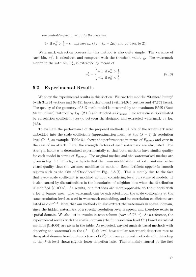
For embedding ωn = −1 into the n-th bin:
4) If σ2′n > 1
3 − α, increase kn (kn = kn + ∆k) and go back to 2);
Watermark extraction process for this method is also quite simple. The variance ofeach bin, σ2′
n , is calculated and compared with the threshold value, 13 . The watermark
hidden in the n-th bin, ω′n, is extracted by means of
ω′n =
{+1, if σ2′
n > 13
−1, if σ2′n < 1
3
(5.13)
5.3 Experimental Results
We show the experimental results in this section. We two test models: ‘Stanford bunny’(with 34,834 vertices and 69,451 faces), davidhead (with 24,085 vertices and 47,753 faces).The quality of the geometry of 3-D mesh model is measured by the maximum RMS (RootMean Square) distance by Eq. (2.15) and denoted as Emrms. The robustness is evaluatedby correlation coefficient (corr), between the designed and extracted watermark by Eq.(4.5).
To evaluate the performance of the proposed methods, 64 bits of the watermark wereembedded into the scale coefficients (approximation mesh) at the (J − 1)-th resolutionlevel CJ−1, as example. Table 5.1 shows the performances in terms of Emrms and corr inthe case of no attack. Here, the strength factors of each watermark are also listed. Thestrength factor α is determined experimentally so that both methods have similar qualityfor each model in terms of Emrms. The original meshes and the watermarked meshes aregiven in Fig. 5.3. This figure depicts that the mean modification method maintains bettervisual quality than the variance modification method. Some artifacts appear in smoothregions such as the skin of ‘Davidhead’ in Fig. 5.3-(f). This is mainly due to the factthat every scale coefficient is modified without considering local curvature of models. Itis also caused by discontinuities in the boundaries of neighbor bins when the distributionis modified [CHO07]. As results, our methods are more applicable to the models witha lot of bumpy area. The watermark can be extracted from the scale coefficients at thesame resolution level as used in watermark embedding, and its correlation coefficients arelisted as corrJ−1. Note that our method can also extract the watermark in spatial domain,since the hidden watermark of a specific resolution level is spread and therefore exists inspatial domain. We also list its results in next column (corr of CJ−1). As a reference, theexperimental results with the spatial domain (the full resolution level CJ) based statisticalmethods [CHO07] are given in the table. As expected, wavelet analysis based methods withdetecting the watermark at the (J − 1)-th level have similar watermark detection rate tothe spatial domain based methods (corr of CJ), but our proposed methods with detectingat the J-th level shows slightly lower detection rate. This is mainly caused by the fact
77
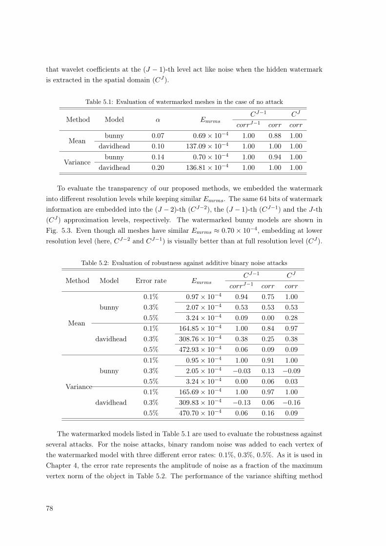
that wavelet coefficients at the (J − 1)-th level act like noise when the hidden watermarkis extracted in the spatial domain (CJ).
Table 5.1: Evaluation of watermarked meshes in the case of no attack
Method Model α EmrmsCJ−1 CJ
corrJ−1 corr corr
Meanbunny 0.07 0.69× 10⁻⁴ 1.00 0.88 1.00
davidhead 0.10 137.09× 10⁻⁴ 1.00 1.00 1.00
Variancebunny 0.14 0.70× 10⁻⁴ 1.00 0.94 1.00
davidhead 0.20 136.81× 10⁻⁴ 1.00 1.00 1.00
To evaluate the transparency of our proposed methods, we embedded the watermarkinto different resolution levels while keeping similar Emrms. The same 64 bits of watermarkinformation are embedded into the (J − 2)-th (CJ−2), the (J − 1)-th (CJ−1) and the J-th(CJ) approximation levels, respectively. The watermarked bunny models are shown inFig. 5.3. Even though all meshes have similar Emrms ≈ 0.70× 10⁻⁴, embedding at lowerresolution level (here, CJ−2 and CJ−1) is visually better than at full resolution level (CJ).
Table 5.2: Evaluation of robustness against additive binary noise attacks
Method Model Error rate EmrmsCJ−1 CJ
corrJ−1 corr corr
Mean
bunny0.1% 0.97× 10⁻⁴ 0.94 0.75 1.000.3% 2.07× 10⁻⁴ 0.53 0.53 0.530.5% 3.24× 10⁻⁴ 0.09 0.00 0.28
davidhead0.1% 164.85× 10⁻⁴ 1.00 0.84 0.970.3% 308.76× 10⁻⁴ 0.38 0.25 0.380.5% 472.93× 10⁻⁴ 0.06 0.09 0.09
Variance
bunny0.1% 0.95× 10⁻⁴ 1.00 0.91 1.000.3% 2.05× 10⁻⁴ −0.03 0.13 −0.090.5% 3.24× 10⁻⁴ 0.00 0.06 0.03
davidhead0.1% 165.69× 10⁻⁴ 1.00 0.97 1.000.3% 309.83× 10⁻⁴ −0.13 0.06 −0.160.5% 470.70× 10⁻⁴ 0.06 0.16 0.09
The watermarked models listed in Table 5.1 are used to evaluate the robustness againstseveral attacks. For the noise attacks, binary random noise was added to each vertex ofthe watermarked model with three different error rates: 0.1%, 0.3%, 0.5%. As it is used inChapter 4, the error rate represents the amplitude of noise as a fraction of the maximumvertex norm of the object in Table 5.2. The performance of the variance shifting method
78
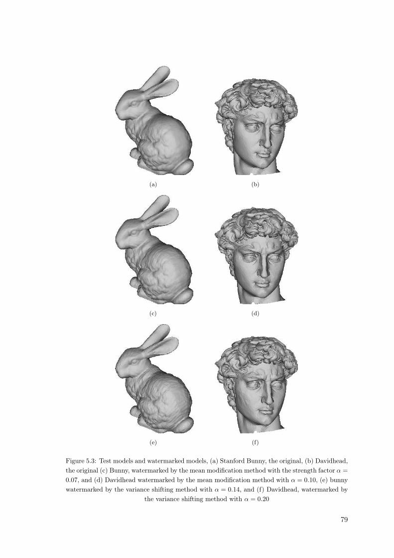
(a) (b)
(c) (d)
(e) (f)
Figure 5.3: Test models and watermarked models, (a) Stanford Bunny, the original, (b) Davidhead,the original (c) Bunny, watermarked by the mean modification method with the strength factor α =0.07, and (d) Davidhead watermarked by the mean modification method with α = 0.10, (e) bunnywatermarked by the variance shifting method with α = 0.14, and (f) Davidhead, watermarked by
the variance shifting method with α = 0.20
79
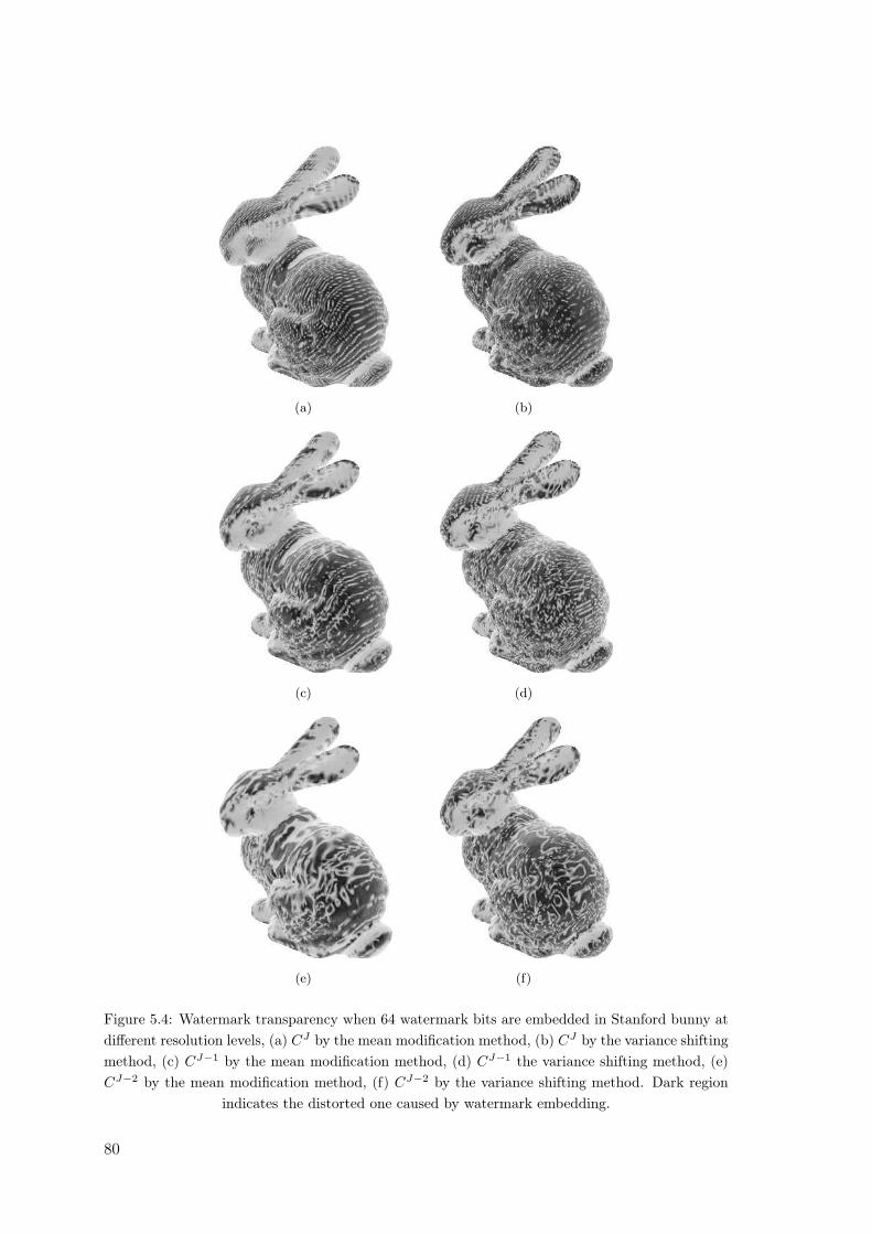
(a) (b)
(c) (d)
(e) (f)
Figure 5.4: Watermark transparency when 64 watermark bits are embedded in Stanford bunny atdifferent resolution levels, (a) CJ by the mean modification method, (b) CJ by the variance shiftingmethod, (c) CJ−1 by the mean modification method, (d) CJ−1 the variance shifting method, (e)CJ−2 by the mean modification method, (f) CJ−2 by the variance shifting method. Dark region
indicates the distorted one caused by watermark embedding.
80
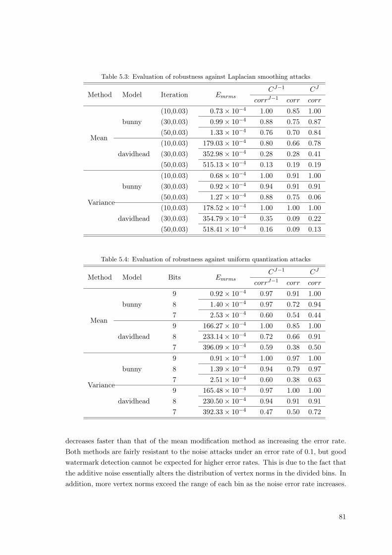
Table 5.3: Evaluation of robustness against Laplacian smoothing attacks
Method Model Iteration EmrmsCJ−1 CJ
corrJ−1 corr corr
Mean
bunny(10,0.03) 0.73× 10⁻⁴ 1.00 0.85 1.00(30,0.03) 0.99× 10⁻⁴ 0.88 0.75 0.87(50,0.03) 1.33× 10⁻⁴ 0.76 0.70 0.84
davidhead(10,0.03) 179.03× 10⁻⁴ 0.80 0.66 0.78(30,0.03) 352.98× 10⁻⁴ 0.28 0.28 0.41(50,0.03) 515.13× 10⁻⁴ 0.13 0.19 0.19
Variance
bunny(10,0.03) 0.68× 10⁻⁴ 1.00 0.91 1.00(30,0.03) 0.92× 10⁻⁴ 0.94 0.91 0.91(50,0.03) 1.27× 10⁻⁴ 0.88 0.75 0.06
davidhead(10,0.03) 178.52× 10⁻⁴ 1.00 1.00 1.00(30,0.03) 354.79× 10⁻⁴ 0.35 0.09 0.22(50,0.03) 518.41× 10⁻⁴ 0.16 0.09 0.13
Table 5.4: Evaluation of robustness against uniform quantization attacks
Method Model Bits EmrmsCJ−1 CJ
corrJ−1 corr corr
Mean
bunny9 0.92× 10⁻⁴ 0.97 0.91 1.008 1.40× 10⁻⁴ 0.97 0.72 0.947 2.53× 10⁻⁴ 0.60 0.54 0.44
davidhead9 166.27× 10⁻⁴ 1.00 0.85 1.008 233.14× 10⁻⁴ 0.72 0.66 0.917 396.09× 10⁻⁴ 0.59 0.38 0.50
Variance
bunny9 0.91× 10⁻⁴ 1.00 0.97 1.008 1.39× 10⁻⁴ 0.94 0.79 0.977 2.51× 10⁻⁴ 0.60 0.38 0.63
davidhead9 165.48× 10⁻⁴ 0.97 1.00 1.008 230.50× 10⁻⁴ 0.94 0.91 0.917 392.33× 10⁻⁴ 0.47 0.50 0.72
decreases faster than that of the mean modification method as increasing the error rate.Both methods are fairly resistant to the noise attacks under an error rate of 0.1, but goodwatermark detection cannot be expected for higher error rates. This is due to the fact thatthe additive noise essentially alters the distribution of vertex norms in the divided bins. Inaddition, more vertex norms exceed the range of each bin as the noise error rate increases.
81
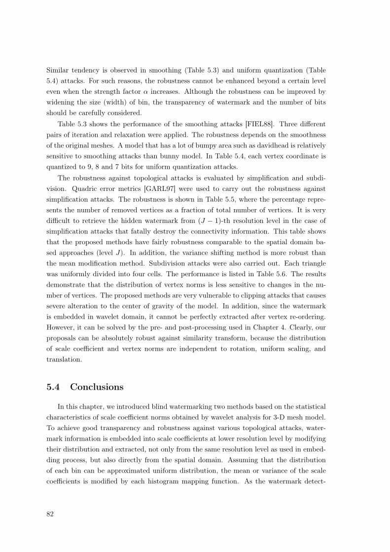
Similar tendency is observed in smoothing (Table 5.3) and uniform quantization (Table5.4) attacks. For such reasons, the robustness cannot be enhanced beyond a certain leveleven when the strength factor α increases. Although the robustness can be improved bywidening the size (width) of bin, the transparency of watermark and the number of bitsshould be carefully considered.
Table 5.3 shows the performance of the smoothing attacks [FIEL88]. Three differentpairs of iteration and relaxation were applied. The robustness depends on the smoothnessof the original meshes. A model that has a lot of bumpy area such as davidhead is relativelysensitive to smoothing attacks than bunny model. In Table 5.4, each vertex coordinate isquantized to 9, 8 and 7 bits for uniform quantization attacks.
The robustness against topological attacks is evaluated by simplification and subdi-vision. Quadric error metrics [GARL97] were used to carry out the robustness againstsimplification attacks. The robustness is shown in Table 5.5, where the percentage repre-sents the number of removed vertices as a fraction of total number of vertices. It is verydifficult to retrieve the hidden watermark from (J − 1)-th resolution level in the case ofsimplification attacks that fatally destroy the connectivity information. This table showsthat the proposed methods have fairly robustness comparable to the spatial domain ba-sed approaches (level J). In addition, the variance shifting method is more robust thanthe mean modification method. Subdivision attacks were also carried out. Each trianglewas uniformly divided into four cells. The performance is listed in Table 5.6. The resultsdemonstrate that the distribution of vertex norms is less sensitive to changes in the nu-mber of vertices. The proposed methods are very vulnerable to clipping attacks that causessevere alteration to the center of gravity of the model. In addition, since the watermarkis embedded in wavelet domain, it cannot be perfectly extracted after vertex re-ordering.However, it can be solved by the pre- and post-processing used in Chapter 4. Clearly, ourproposals can be absolutely robust against similarity transform, because the distributionof scale coefficient and vertex norms are independent to rotation, uniform scaling, andtranslation.
5.4 Conclusions
In this chapter, we introduced blind watermarking two methods based on the statisticalcharacteristics of scale coefficient norms obtained by wavelet analysis for 3-D mesh model.To achieve good transparency and robustness against various topological attacks, water-mark information is embedded into scale coefficients at lower resolution level by modifyingtheir distribution and extracted, not only from the same resolution level as used in embed-ding process, but also directly from the spatial domain. Assuming that the distributionof each bin can be approximated uniform distribution, the mean or variance of the scalecoefficients is modified by each histogram mapping function. As the watermark detect-
82
Table 5.5: Evaluation of robustness against simplification attacks
Method ModelReduction
ratioEmrms
CJ−1 CJ
corrJ−1 corr corr
Mean
bunny
30% 0.75× 10⁻⁴ - 0.72 1.0050% 0.80× 10⁻⁴ - 0.69 0.8870% 0.92× 10⁻⁴ - 0.48 0.5890% 3.44× 10⁻⁴ - 0.06 0.42
davidhead
30% 352.37× 10⁻⁴ - 0.91 0.8550% 422.06× 10⁻⁴ - 0.78 0.8170% 581.23× 10⁻⁴ - 0.85 0.8590% 1015.49× 10−4 - 0.16 0.35
Variance
bunny
30% 0.73× 10⁻⁴ - 0.78 1.0050% 0.77× 10⁻⁴ - 0.81 0.9770% 0.90× 10⁻⁴ - 0.81 0.9490% 3.12× 10⁻⁴ - 0.76 0.88
davidhead
30% 509.21× 10⁻⁴ - 0.91 1.0050% 573.84× 10⁻⁴ - 0.91 0.9470% 695.56× 10⁻⁴ - 0.91 0.9490% 1419.40× 10−4 - 0.34 0.28
Table 5.6: Evaluation of robustness against 1-to-4 subdivision attacks
Method Model EmrmsCJ−1 CJ
corrJ−1 corr corr
Meanbunny 0.69× 10⁻⁴ - 0.76 1.00
davidhead 136.29× 10⁻⁴ - 0.48 0.94
Variancebunny 0.69× 10⁻⁴ - 0.88 1.00
davidhead 135.04× 10⁻⁴ - 0.94 0.97
ion processes in spatial domain do not require wavelet analysis or any pre-processing, theembedded watermark can be simply calculate the mean or variance of each bin. Throughsimulations, we proved that the proposed methods have fairly good performance in termsof the watermark transparency and robustness against various attacks. Even though theproposed methods are not highly robust comparing with spatial domain based methods,our attempts demonstrate a possibility, blind watermarking based on wavelet analysis for3-D mesh model.
83

84
Part II
Wavelet Transform Based DigitalWatermarking for 3-D Mesh
Sequences
85

Chapter 6
Digital Watermarking Using theStatistical Features of Distribution
In this chapter, we introduce digital watermarking methods for 3-D mesh sequencesbased on temporal wavelet transform. This work was published in [KIM06c].
6.1 Introduction
In the previous chapter (Chapter 5), we proved that statistical features of the signal suchas the mean value and the variance can be a good watermark embedding carrier. Similarto our previous works, we propose, in this chapter, two 3-D mesh sequence watermarkingmethods using the variance of temporal wavelet coefficients.
Assuming that the original mesh sequence is isomorphic one (i.e., the connectivityinformation of original 3-D mesh sequence is never changed over all frames), it can beregarded as a set of 1-D signals which consists of the geometry information with the samevertex index along the time axis.
The proposed methods decompose each 1-D signal into several sub-bands, and modifya specific sub-band to embed watermark bits. To decompose 1-D signal, wavelet transformis applied to these 1-D signals.
In order to select the sub-band for watermark embedding, we should consider therobustness and the invisibility. From the view point of the robustness, the watermarkwhich is embedded in low frequency band can be more efficient. It is caused by thefact that the low frequency band signal is less sensitive to most signal processing since itcontains most energy of signal. From the view point of the transparency, the watermarkwhich is embedded in high frequency can be more efficient. In order to use the advantagesof each sub-band, we modify the high frequency band signal to embed watermark, referringthe lowest frequency band signal. Since wavelet transform can decompose both frequencycomponents as well as temporal components, we can easily select high frequency coefficients
87
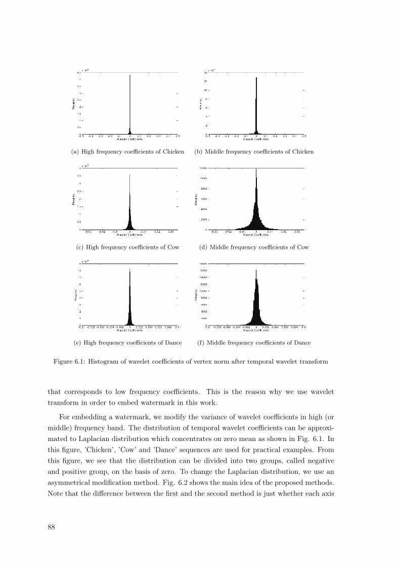
(a) High frequency coefficients of Chicken (b) Middle frequency coefficients of Chicken
(c) High frequency coefficients of Cow (d) Middle frequency coefficients of Cow
(e) High frequency coefficients of Dance (f) Middle frequency coefficients of Dance
Figure 6.1: Histogram of wavelet coefficients of vertex norm after temporal wavelet transform
that corresponds to low frequency coefficients. This is the reason why we use wavelettransform in order to embed watermark in this work.
For embedding a watermark, we modify the variance of wavelet coefficients in high (ormiddle) frequency band. The distribution of temporal wavelet coefficients can be approxi-mated to Laplacian distribution which concentrates on zero mean as shown in Fig. 6.1. Inthis figure, ’Chicken’, ’Cow’ and ’Dance’ sequences are used for practical examples. Fromthis figure, we see that the distribution can be divided into two groups, called negativeand positive group, on the basis of zero. To change the Laplacian distribution, we use anasymmetrical modification method. Fig. 6.2 shows the main idea of the proposed methods.Note that the difference between the first and the second method is just whether each axis
88
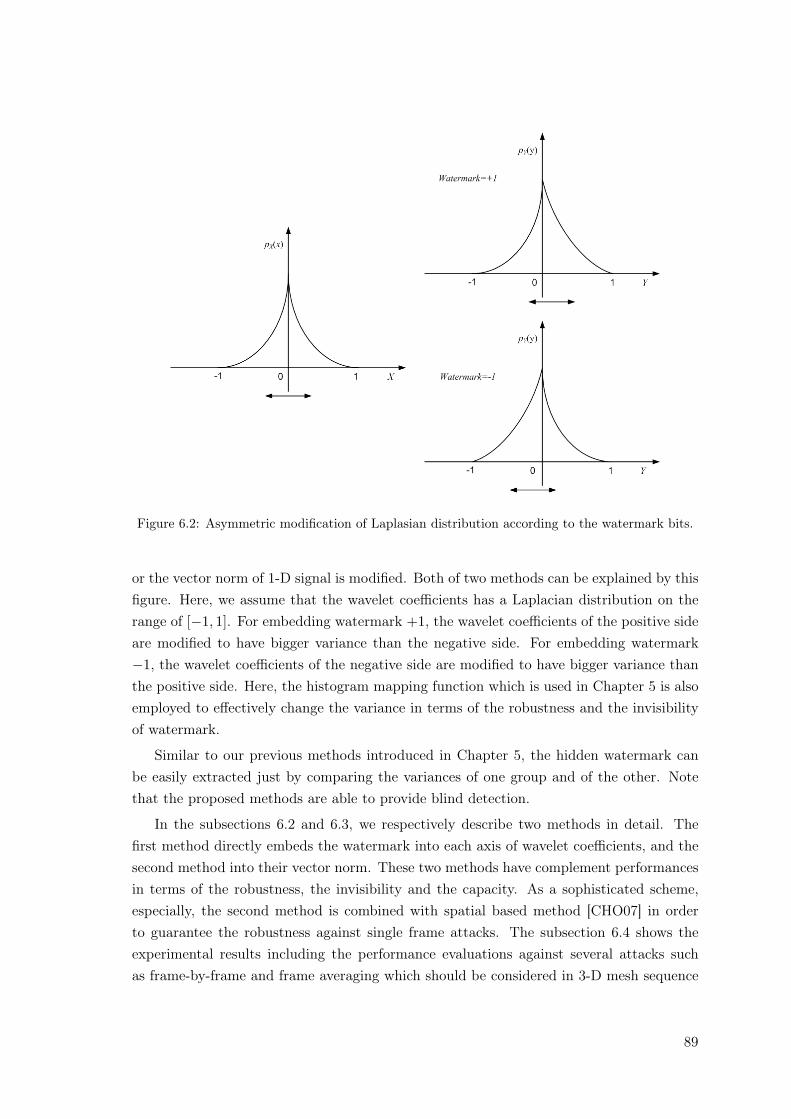
Figure 6.2: Asymmetric modification of Laplasian distribution according to the watermark bits.
or the vector norm of 1-D signal is modified. Both of two methods can be explained by thisfigure. Here, we assume that the wavelet coefficients has a Laplacian distribution on therange of [−1, 1]. For embedding watermark +1, the wavelet coefficients of the positive sideare modified to have bigger variance than the negative side. For embedding watermark−1, the wavelet coefficients of the negative side are modified to have bigger variance thanthe positive side. Here, the histogram mapping function which is used in Chapter 5 is alsoemployed to effectively change the variance in terms of the robustness and the invisibilityof watermark.
Similar to our previous methods introduced in Chapter 5, the hidden watermark canbe easily extracted just by comparing the variances of one group and of the other. Notethat the proposed methods are able to provide blind detection.
In the subsections 6.2 and 6.3, we respectively describe two methods in detail. Thefirst method directly embeds the watermark into each axis of wavelet coefficients, and thesecond method into their vector norm. These two methods have complement performancesin terms of the robustness, the invisibility and the capacity. As a sophisticated scheme,especially, the second method is combined with spatial based method [CHO07] in orderto guarantee the robustness against single frame attacks. The subsection 6.4 shows theexperimental results including the performance evaluations against several attacks suchas frame-by-frame and frame averaging which should be considered in 3-D mesh sequence
89
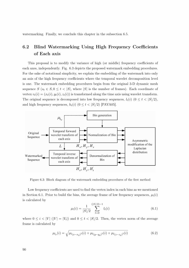
watermarking. Finally, we conclude this chapter in the subsection 6.5.
6.2 Blind Watermarking Using High Frequency Coefficientsof Each axis
This proposal is to modify the variance of high (or middle) frequency coefficients ofeach axes, independently. Fig. 6.3 depicts the proposed watermark embedding procedures.For the sake of notational simplicity, we explain the embedding of the watermark into onlyan axis of the high frequency coefficients where the temporal wavelet decomposition levelis one. The watermark embedding procedures begin from the original 3-D dynamic meshsequence S (st ∈ S, 0 ≤ t < |S|, where |S| is the number of frames). Each coordinate ofvertex vt(i) = (xt(i), yt(i), zt(i)) is transformed along the time axis using wavelet transform.The original sequence is decomposed into low frequency sequences, lt(i) (0 ≤ t < |S|/2),and high frequency sequences, ht(i) (0 ≤ t < |S|/2) [PAYA05].
Figure 6.3: Block diagram of the watermark embedding procedures of the first method
Low frequency coefficients are used to find the vertex index in each bins as we mentionedin Section 6.1. Prior to build the bins, the average frame of low frequency sequences, µl(i)is calculated by
µl(i) =1
|S|/2
(|S|/2)−1∑
t=0
lt(i) (6.1)
where 0 ≤ i < |V | (|V | = |Vt|) and 0 ≤ t < |S|/2. Then, the vertex norm of the averageframe is calculated by
µlρ(i) =√
µl(x−xg)2(i) + µl(y−yg)2(i) + µl(z−zg)2(i) (6.2)
90
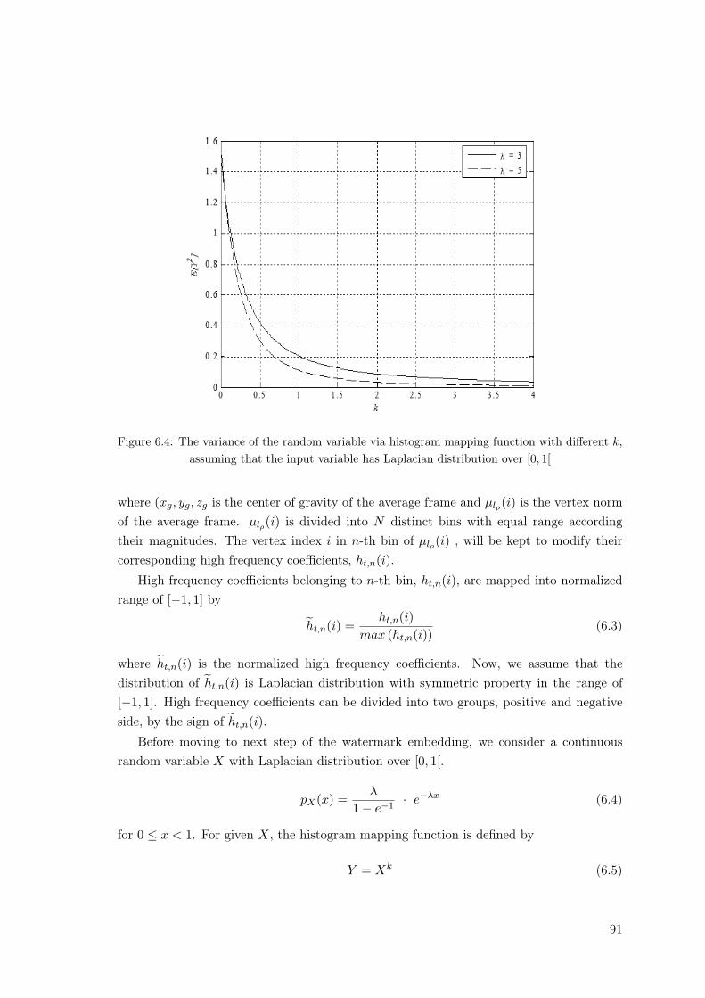
Figure 6.4: The variance of the random variable via histogram mapping function with different k,assuming that the input variable has Laplacian distribution over [0, 1[
where (xg, yg, zg is the center of gravity of the average frame and µlρ(i) is the vertex normof the average frame. µlρ(i) is divided into N distinct bins with equal range accordingtheir magnitudes. The vertex index i in n-th bin of µlρ(i) , will be kept to modify theircorresponding high frequency coefficients, ht,n(i).
High frequency coefficients belonging to n-th bin, ht,n(i), are mapped into normalizedrange of [−1, 1] by
ht,n(i) =ht,n(i)
max (ht,n(i))(6.3)
where ht,n(i) is the normalized high frequency coefficients. Now, we assume that thedistribution of ht,n(i) is Laplacian distribution with symmetric property in the range of[−1, 1]. High frequency coefficients can be divided into two groups, positive and negativeside, by the sign of ht,n(i).
Before moving to next step of the watermark embedding, we consider a continuousrandom variable X with Laplacian distribution over [0, 1[.
pX(x) =λ
1− e−1· e−λx (6.4)
for 0 ≤ x < 1. For given X, the histogram mapping function is defined by
Y = Xk (6.5)
91
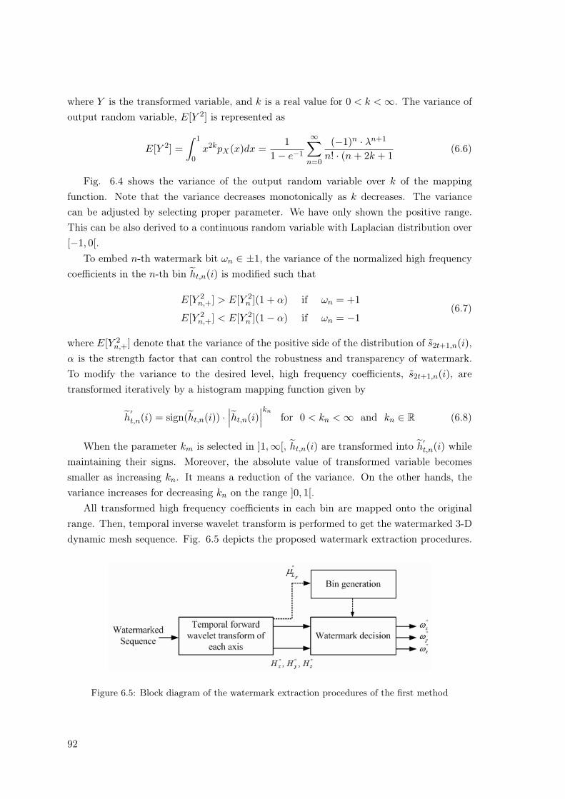
where Y is the transformed variable, and k is a real value for 0 < k < ∞. The variance ofoutput random variable, E[Y 2] is represented as
E[Y 2] =∫ 1
0x2kpX(x)dx =
11− e−1
∞∑
n=0
(−1)n · λn+1
n! · (n + 2k + 1(6.6)
Fig. 6.4 shows the variance of the output random variable over k of the mappingfunction. Note that the variance decreases monotonically as k decreases. The variancecan be adjusted by selecting proper parameter. We have only shown the positive range.This can be also derived to a continuous random variable with Laplacian distribution over[−1, 0[.
To embed n-th watermark bit ωn ∈ ±1, the variance of the normalized high frequencycoefficients in the n-th bin ht,n(i) is modified such that
E[Y 2n,+] > E[Y 2
n ](1 + α) if ωn = +1
E[Y 2n,+] < E[Y 2
n ](1− α) if ωn = −1(6.7)
where E[Y 2n,+] denote that the variance of the positive side of the distribution of s2t+1,n(i),
α is the strength factor that can control the robustness and transparency of watermark.To modify the variance to the desired level, high frequency coefficients, s2t+1,n(i), aretransformed iteratively by a histogram mapping function given by
h′t,n(i) = sign(ht,n(i)) ·
∣∣∣ht,n(i)∣∣∣kn
for 0 < kn < ∞ and kn ∈ R (6.8)
When the parameter km is selected in ]1,∞[, ht,n(i) are transformed into h′t,n(i) while
maintaining their signs. Moreover, the absolute value of transformed variable becomessmaller as increasing kn. It means a reduction of the variance. On the other hands, thevariance increases for decreasing kn on the range ]0, 1[.
All transformed high frequency coefficients in each bin are mapped onto the originalrange. Then, temporal inverse wavelet transform is performed to get the watermarked 3-Ddynamic mesh sequence. Fig. 6.5 depicts the proposed watermark extraction procedures.
Figure 6.5: Block diagram of the watermark extraction procedures of the first method
92
Similar to the watermark embedding, each axis of vertex coordinates of the watermarked3-D mesh sequence S′′ is temporal wavelet transformed. The vertex norm of the averageframe µl′′ρ
(i) divided into N distinct bins with equal range according their magnitudes.
High frequency coefficients belonging to n-th bin, h′′t,n(i), are mapped into normalized
range of [−1, 1]. The normalized high frequency coefficients h′t,n(i) in each bin are grouped
into positive and negative side according to the sign of h′t,n(i). The variance of positive
and negative side, E[Y 2′′n,+] and E[Y 2′′
n,−], of n-th bin, is calculated and compared each other.The watermark hidden in the n-th bin is extracted by means of,
ω′′n =
{+1, if E[Y 2′′
n,+] > E[Y 2′′n,−]
−1, if E[Y 2′′n,+] < E[Y 2′′
n,−](6.9)
Note that the watermark extraction process does not require the original mesh sequence.
6.3 Blind Watermarking Using High Frequency Coefficientsof Vertex Norms
The proposed method in this section also uses the distribution of temporally high fre-quency coefficients. In sharp contrast to the first method, vertex norms are only used inthe watermark embedding and extraction procedures. In addition, we propose combinedwatermarking method to modify the distribution of low frequency coefficients by the me-thod introduced in [CHO07] as well as high frequency coefficients of vertex norms. For thesake of notational simplicity, we use the same notation as the previous section.
6.3.1 Modification of High Frequency Coefficients of Vertex Norms
Fig. 6.6 depicts the watermark embedding the method. From the original 3-D dy-namic mesh sequence S the center of gravity of each frame is translated to the origin aspre-processing to compute wavelet coefficients. Each frame st, all vertices of Cartesiancoordinates, vt(i) = (xt(i), yt(i), zt(i)), are converted to Spherical coordinates, vt(i) =(ρt(i), θt(i), ρt(i)) by
ρt(i) =√
(xt(i)− µxt)2 + (yt(i)− µyt)2 + (zt(i)− µzt)2
θt(i) = tan−1 yt(i)− µyt
xt(i)− µxt
for 0 ≤ i < |v| and 0 ≤ t < |S| (6.10)
φt(i) = cos−1 zt(i)− µzt√(xt(i)− µxt)2 + (yt(i)− µyt)2 + (zt(i)− µzt)2
where (µxt , µyt , µzt) is the center of gravity of st.The vertex norm, ρt(i) is transformed along the time axis using wavelet transform. The
original sequence is decomposed into low frequency coefficients, lt(i) (0 ≤ t < |S|/2), andhigh frequency coefficients, ht(i) (0 ≤ t < |S|/2).
93
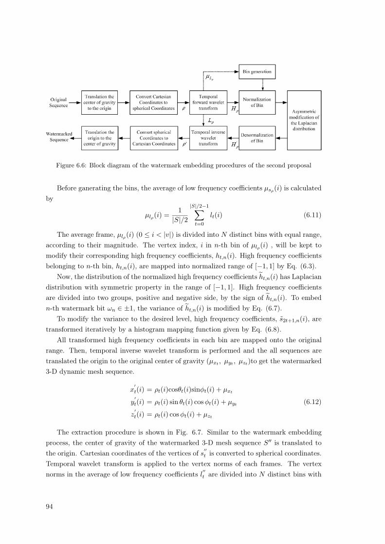
Figure 6.6: Block diagram of the watermark embedding procedures of the second proposal
Before ganerating the bins, the average of low frequency coefficients µsρ(i) is calculatedby
µlρ(i) =1
|S|/2
|S|/2−1∑
t=0
lt(i) (6.11)
The average frame, µlρ(i) (0 ≤ i < |v|) is divided into N distinct bins with equal range,according to their magnitude. The vertex index, i in n-th bin of µlρ(i) , will be kept tomodify their corresponding high frequency coefficients, ht,n(i). High frequency coefficientsbelonging to n-th bin, ht,n(i), are mapped into normalized range of [−1, 1] by Eq. (6.3).
Now, the distribution of the normalized high frequency coefficients ht,n(i) has Laplaciandistribution with symmetric property in the range of [−1, 1]. High frequency coefficientsare divided into two groups, positive and negative side, by the sign of ht,n(i). To embedn-th watermark bit ωn ∈ ±1, the variance of ht,n(i) is modified by Eq. (6.7).
To modify the variance to the desired level, high frequency coefficients, s2t+1,n(i), aretransformed iteratively by a histogram mapping function given by Eq. (6.8).
All transformed high frequency coefficients in each bin are mapped onto the originalrange. Then, temporal inverse wavelet transform is performed and the all sequences aretranslated the origin to the original center of gravity (µxt , µyt , µzt)to get the watermarked3-D dynamic mesh sequence.
x′t(i) = ρt(i)cosθt(i)sinφt(i) + µxt
y′t(i) = ρt(i) sin θt(i) cos φt(i) + µyt (6.12)
z′t(i) = ρt(i) cos φt(i) + µzt
The extraction procedure is shown in Fig. 6.7. Similar to the watermark embeddingprocess, the center of gravity of the watermarked 3-D mesh sequence S′′ is translated tothe origin. Cartesian coordinates of the vertices of s
′′t is converted to spherical coordinates.
Temporal wavelet transform is applied to the vertex norms of each frames. The vertexnorms in the average of low frequency coefficients l
′′t are divided into N distinct bins with
94
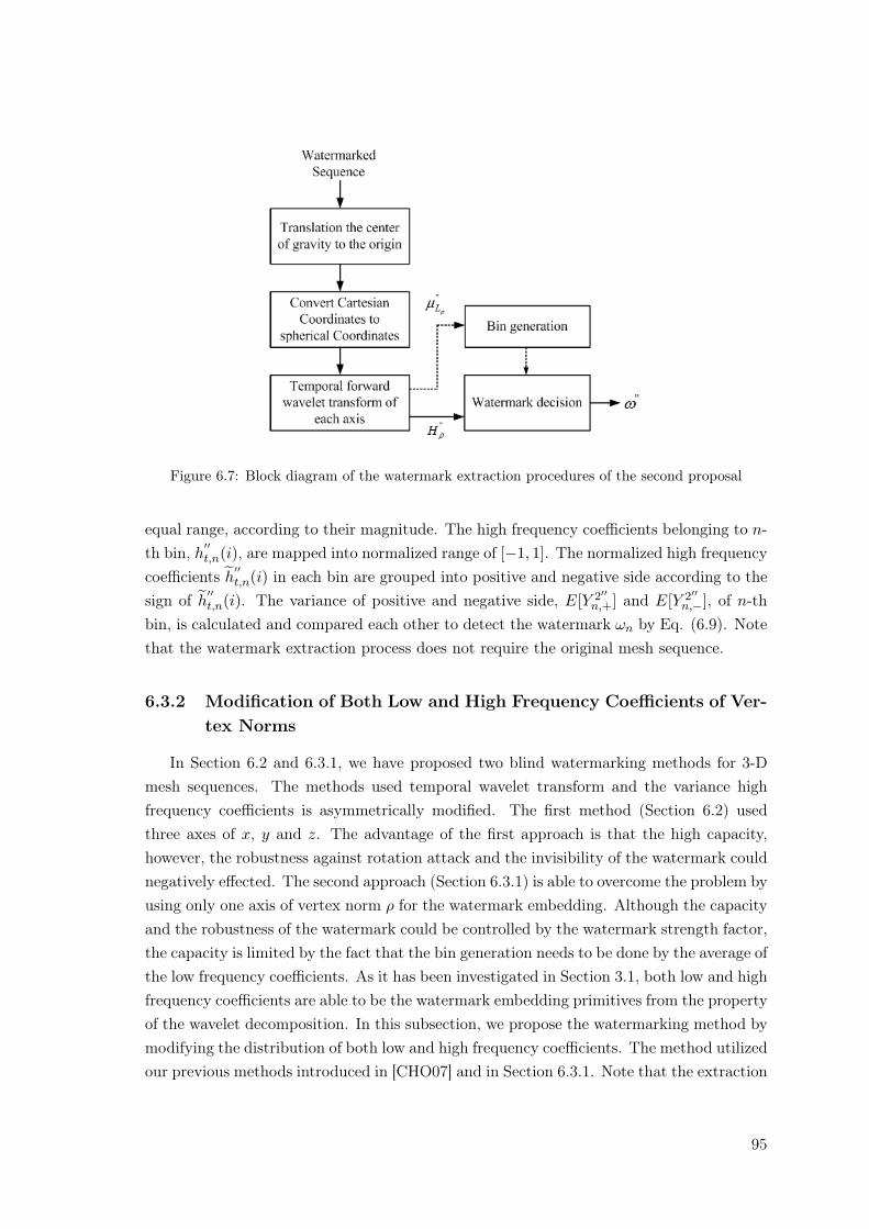
Figure 6.7: Block diagram of the watermark extraction procedures of the second proposal
equal range, according to their magnitude. The high frequency coefficients belonging to n-th bin, h
′′t,n(i), are mapped into normalized range of [−1, 1]. The normalized high frequency
coefficients h′′t,n(i) in each bin are grouped into positive and negative side according to the
sign of h′′t,n(i). The variance of positive and negative side, E[Y 2′′
n,+] and E[Y 2′′n,−], of n-th
bin, is calculated and compared each other to detect the watermark ωn by Eq. (6.9). Notethat the watermark extraction process does not require the original mesh sequence.
6.3.2 Modification of Both Low and High Frequency Coefficients of Ver-tex Norms
In Section 6.2 and 6.3.1, we have proposed two blind watermarking methods for 3-Dmesh sequences. The methods used temporal wavelet transform and the variance highfrequency coefficients is asymmetrically modified. The first method (Section 6.2) usedthree axes of x, y and z. The advantage of the first approach is that the high capacity,however, the robustness against rotation attack and the invisibility of the watermark couldnegatively effected. The second approach (Section 6.3.1) is able to overcome the problem byusing only one axis of vertex norm ρ for the watermark embedding. Although the capacityand the robustness of the watermark could be controlled by the watermark strength factor,the capacity is limited by the fact that the bin generation needs to be done by the average ofthe low frequency coefficients. As it has been investigated in Section 3.1, both low and highfrequency coefficients are able to be the watermark embedding primitives from the propertyof the wavelet decomposition. In this subsection, we propose the watermarking method bymodifying the distribution of both low and high frequency coefficients. The method utilizedour previous methods introduced in [CHO07] and in Section 6.3.1. Note that the extraction
95
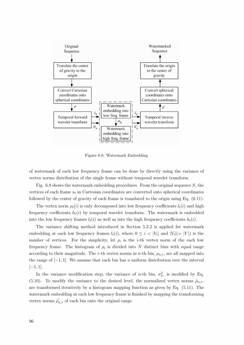
Figure 6.8: Watermark Embedding
of watermark of each low frequency frame can be done by directly using the variance ofvertex norms distribution of the single frame without temporal wavelet transform.
Fig. 6.8 shows the watermark embedding procedures. From the original sequence S, thevertices of each frame st in Cartesian coordinates are converted onto spherical coordinatesfollowed by the center of gravity of each frame is translated to the origin using Eq. (6.11).
The vertex norm ρt(i) is only decomposed into low frequency coefficients lt(i) and highfrequency coefficients ht(i) by temporal wavelet transform. The watermark is embeddedinto the low frequency frames lt(i) as well as into the high frequency coefficients ht(i).
The variance shifting method introduced in Section 5.2.2 is applied for watermarkembedding at each low frequency frames lt(i), where 0 ≤ i < |Vt| and |Vt|(= |V |) is thenumber of vertices. For the simplicity, let ρi is the i-th vertex norm of the each lowfrequency frame. The histogram of ρi is divided into N distinct bins with equal rangeaccording to their magnitude. The r-th vertex norms in n-th bin, ρn,r, are all mapped intothe range of [−1, 1]. We assume that each bin has a uniform distribution over the interval[−1, 1].
In the variance modification step, the variance of n-th bin, σ2n, is modified by Eq.
(5.10). To modify the variance to the desired level, the normalized vertex norms ρn,r,are transformed iteratively by a histogram mapping function as given by Eq. (5.11). Thewatermark embedding at each low frequency frame is finished by mapping the transformingvertex norms ρ
′n,r of each bin onto the original range.
96
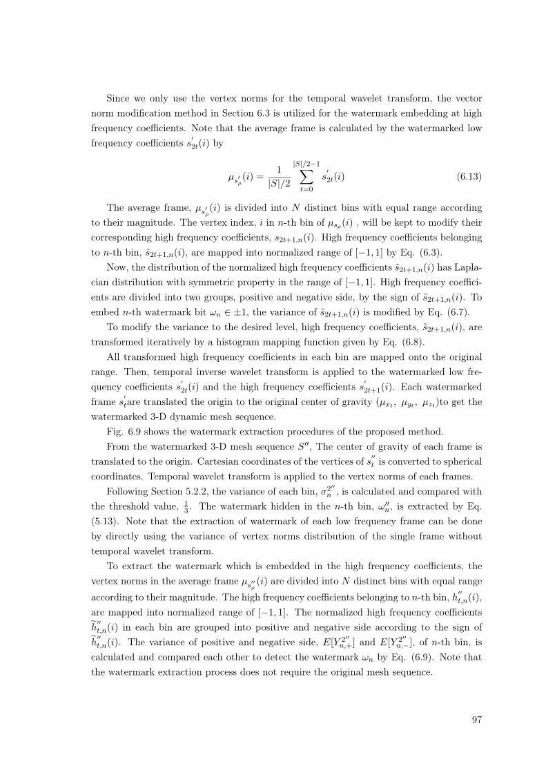
Since we only use the vertex norms for the temporal wavelet transform, the vectornorm modification method in Section 6.3 is utilized for the watermark embedding at highfrequency coefficients. Note that the average frame is calculated by the watermarked lowfrequency coefficients s
′2t(i) by
µs′ρ(i) =
1|S|/2
|S|/2−1∑
t=0
s′2t(i) (6.13)
The average frame, µs′ρ(i) is divided into N distinct bins with equal range according
to their magnitude. The vertex index, i in n-th bin of µsρ(i) , will be kept to modify theircorresponding high frequency coefficients, s2t+1,n(i). High frequency coefficients belongingto n-th bin, s2t+1,n(i), are mapped into normalized range of [−1, 1] by Eq. (6.3).
Now, the distribution of the normalized high frequency coefficients s2t+1,n(i) has Lapla-cian distribution with symmetric property in the range of [−1, 1]. High frequency coeffici-ents are divided into two groups, positive and negative side, by the sign of s2t+1,n(i). Toembed n-th watermark bit ωn ∈ ±1, the variance of s2t+1,n(i) is modified by Eq. (6.7).
To modify the variance to the desired level, high frequency coefficients, s2t+1,n(i), aretransformed iteratively by a histogram mapping function given by Eq. (6.8).
All transformed high frequency coefficients in each bin are mapped onto the originalrange. Then, temporal inverse wavelet transform is applied to the watermarked low fre-quency coefficients s
′2t(i) and the high frequency coefficients s
′2t+1(i). Each watermarked
frame s′tare translated the origin to the original center of gravity (µxt , µyt , µzt)to get the
watermarked 3-D dynamic mesh sequence.Fig. 6.9 shows the watermark extraction procedures of the proposed method.From the watermarked 3-D mesh sequence S′′, The center of gravity of each frame is
translated to the origin. Cartesian coordinates of the vertices of s′′t is converted to spherical
coordinates. Temporal wavelet transform is applied to the vertex norms of each frames.Following Section 5.2.2, the variance of each bin, σ2′′
n , is calculated and compared withthe threshold value, 1
3 . The watermark hidden in the n-th bin, ω′′n, is extracted by Eq.(5.13). Note that the extraction of watermark of each low frequency frame can be doneby directly using the variance of vertex norms distribution of the single frame withouttemporal wavelet transform.
To extract the watermark which is embedded in the high frequency coefficients, thevertex norms in the average frame µs′′ρ
(i) are divided into N distinct bins with equal range
according to their magnitude. The high frequency coefficients belonging to n-th bin, h′′t,n(i),are mapped into normalized range of [−1, 1]. The normalized high frequency coefficientsh′′t,n(i) in each bin are grouped into positive and negative side according to the sign of
h′′t,n(i). The variance of positive and negative side, E[Y 2′′
n,+] and E[Y 2′′n,−], of n-th bin, is
calculated and compared each other to detect the watermark ωn by Eq. (6.9). Note thatthe watermark extraction process does not require the original mesh sequence.
97
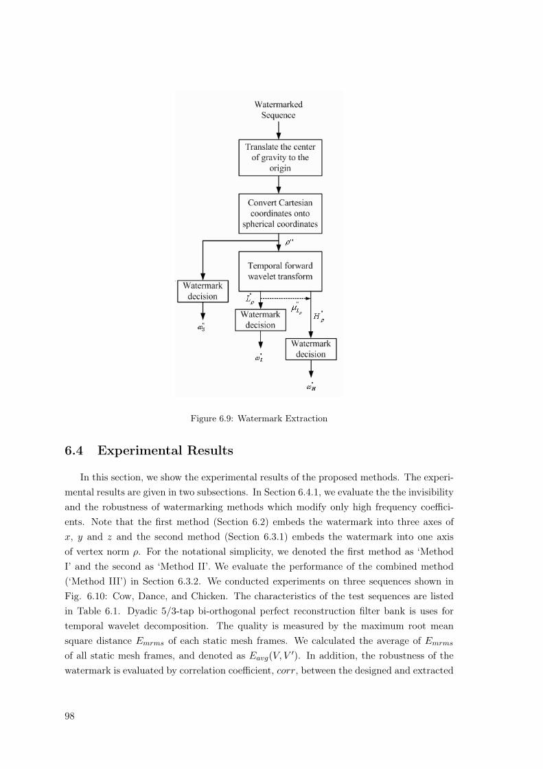
Figure 6.9: Watermark Extraction
6.4 Experimental Results
In this section, we show the experimental results of the proposed methods. The experi-mental results are given in two subsections. In Section 6.4.1, we evaluate the the invisibilityand the robustness of watermarking methods which modify only high frequency coeffici-ents. Note that the first method (Section 6.2) embeds the watermark into three axes ofx, y and z and the second method (Section 6.3.1) embeds the watermark into one axisof vertex norm ρ. For the notational simplicity, we denoted the first method as ‘MethodI’ and the second as ‘Method II’. We evaluate the performance of the combined method(‘Method III’) in Section 6.3.2. We conducted experiments on three sequences shown inFig. 6.10: Cow, Dance, and Chicken. The characteristics of the test sequences are listedin Table 6.1. Dyadic 5/3-tap bi-orthogonal perfect reconstruction filter bank is uses fortemporal wavelet decomposition. The quality is measured by the maximum root meansquare distance Emrms of each static mesh frames. We calculated the average of Emrms
of all static mesh frames, and denoted as Eavg(V, V ′). In addition, the robustness of thewatermark is evaluated by correlation coefficient, corr, between the designed and extracted
98
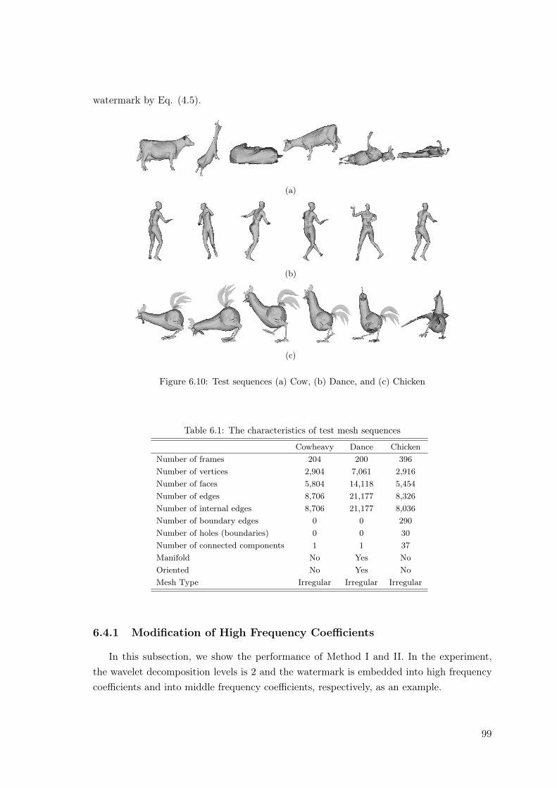
watermark by Eq. (4.5).
(a)
(b)
(c)
Figure 6.10: Test sequences (a) Cow, (b) Dance, and (c) Chicken
Table 6.1: The characteristics of test mesh sequences
Cowheavy Dance ChickenNumber of frames 204 200 396Number of vertices 2,904 7,061 2,916Number of faces 5,804 14,118 5,454Number of edges 8,706 21,177 8,326Number of internal edges 8,706 21,177 8,036Number of boundary edges 0 0 290Number of holes (boundaries) 0 0 30Number of connected components 1 1 37Manifold No Yes NoOriented No Yes NoMesh Type Irregular Irregular Irregular
6.4.1 Modification of High Frequency Coefficients
In this subsection, we show the performance of Method I and II. In the experiment,the wavelet decomposition levels is 2 and the watermark is embedded into high frequencycoefficients and into middle frequency coefficients, respectively, as an example.
99
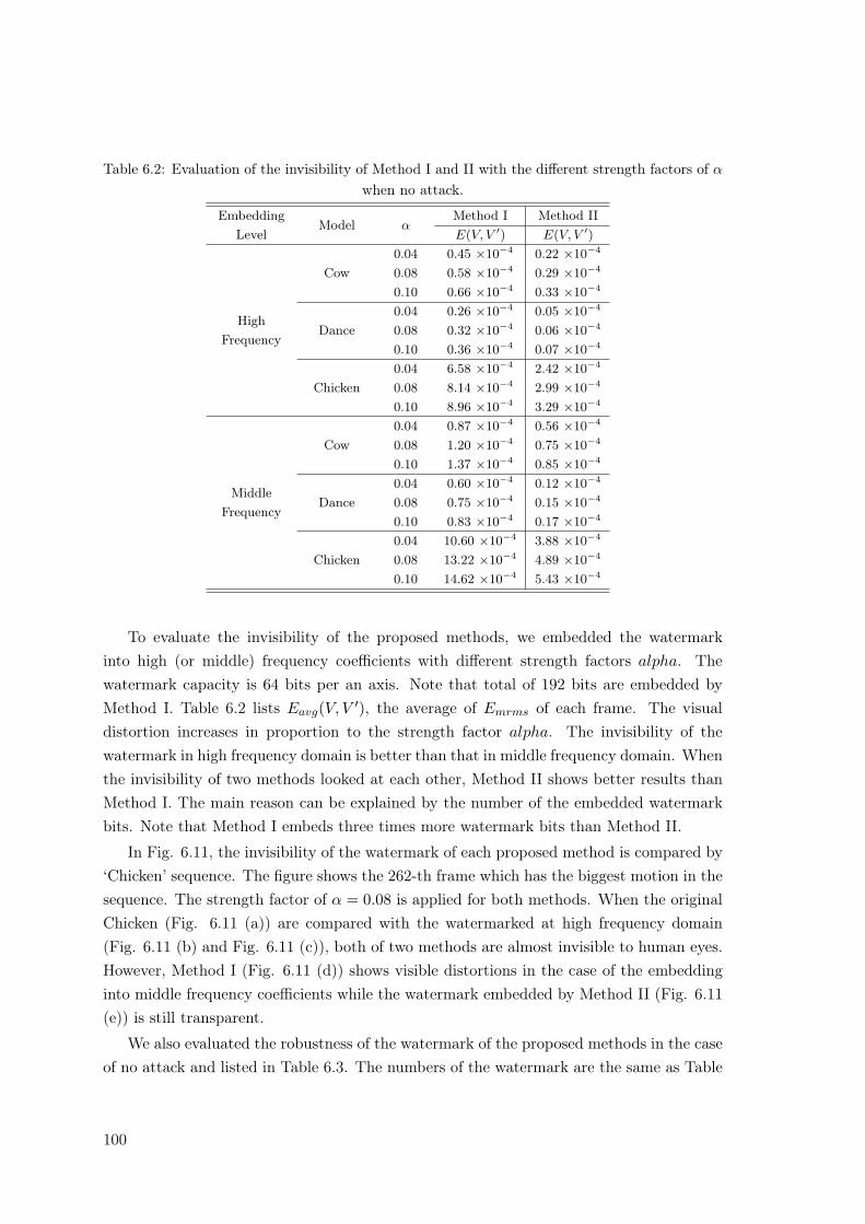
Table 6.2: Evaluation of the invisibility of Method I and II with the different strength factors of α
when no attack.
EmbeddingLevel
Model αMethod I Method IIE(V, V ′) E(V, V ′)
HighFrequency
Cow0.04 0.45 ×10⁻⁴ 0.22 ×10⁻⁴
0.08 0.58 ×10⁻⁴ 0.29 ×10⁻⁴
0.10 0.66 ×10⁻⁴ 0.33 ×10⁻⁴
Dance0.04 0.26 ×10⁻⁴ 0.05 ×10⁻⁴
0.08 0.32 ×10⁻⁴ 0.06 ×10⁻⁴
0.10 0.36 ×10⁻⁴ 0.07 ×10⁻⁴
Chicken0.04 6.58 ×10⁻⁴ 2.42 ×10⁻⁴
0.08 8.14 ×10⁻⁴ 2.99 ×10⁻⁴
0.10 8.96 ×10⁻⁴ 3.29 ×10⁻⁴
MiddleFrequency
Cow0.04 0.87 ×10⁻⁴ 0.56 ×10⁻⁴
0.08 1.20 ×10⁻⁴ 0.75 ×10⁻⁴
0.10 1.37 ×10⁻⁴ 0.85 ×10⁻⁴
Dance0.04 0.60 ×10⁻⁴ 0.12 ×10⁻⁴
0.08 0.75 ×10⁻⁴ 0.15 ×10⁻⁴
0.10 0.83 ×10⁻⁴ 0.17 ×10⁻⁴
Chicken0.04 10.60 ×10⁻⁴ 3.88 ×10⁻⁴
0.08 13.22 ×10⁻⁴ 4.89 ×10⁻⁴
0.10 14.62 ×10⁻⁴ 5.43 ×10⁻⁴
To evaluate the invisibility of the proposed methods, we embedded the watermarkinto high (or middle) frequency coefficients with different strength factors alpha. Thewatermark capacity is 64 bits per an axis. Note that total of 192 bits are embedded byMethod I. Table 6.2 lists Eavg(V, V ′), the average of Emrms of each frame. The visualdistortion increases in proportion to the strength factor alpha. The invisibility of thewatermark in high frequency domain is better than that in middle frequency domain. Whenthe invisibility of two methods looked at each other, Method II shows better results thanMethod I. The main reason can be explained by the number of the embedded watermarkbits. Note that Method I embeds three times more watermark bits than Method II.
In Fig. 6.11, the invisibility of the watermark of each proposed method is compared by‘Chicken’ sequence. The figure shows the 262-th frame which has the biggest motion in thesequence. The strength factor of α = 0.08 is applied for both methods. When the originalChicken (Fig. 6.11 (a)) are compared with the watermarked at high frequency domain(Fig. 6.11 (b) and Fig. 6.11 (c)), both of two methods are almost invisible to human eyes.However, Method I (Fig. 6.11 (d)) shows visible distortions in the case of the embeddinginto middle frequency coefficients while the watermark embedded by Method II (Fig. 6.11(e)) is still transparent.
We also evaluated the robustness of the watermark of the proposed methods in the caseof no attack and listed in Table 6.3. The numbers of the watermark are the same as Table
100
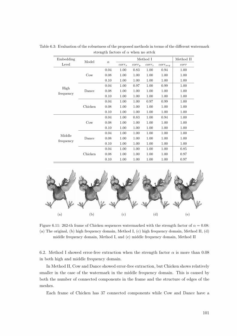
Table 6.3: Evaluation of the robustness of the proposed methods in terms of the different watermarkstrength factors of α when no attck
EmbeddingLevel
Model αMethod I Method II
corrx corry corrz corravg corr
Highfrequency
Cow0.04 1.00 0.83 1.00 0.94 1.000.08 1.00 1.00 1.00 1.00 1.000.10 1.00 1.00 1.00 1.00 1.00
Dance0.04 1.00 0.97 1.00 0.99 1.000.08 1.00 1.00 1.00 1.00 1.000.10 1.00 1.00 1.00 1.00 1.00
Chicken0.04 1.00 1.00 0.97 0.99 1.000.08 1.00 1.00 1.00 1.00 1.000.10 1.00 1.00 1.00 1.00 1.00
Middlefrequency
Cow0.04 1.00 0.83 1.00 0.94 1.000.08 1.00 1.00 1.00 1.00 1.000.10 1.00 1.00 1.00 1.00 1.00
Dance0.04 1.00 1.00 1.00 1.00 1.000.08 1.00 1.00 1.00 1.00 1.000.10 1.00 1.00 1.00 1.00 1.00
Chicken0.04 1.00 1.00 1.00 1.00 0.850.08 1.00 1.00 1.00 1.00 0.970.10 1.00 1.00 1.00 1.00 0.97
(a) (b) (c) (d) (e)
Figure 6.11: 262-th frame of Chicken sequences watermarked with the strength factor of α = 0.08:(a) The original, (b) high frequency domain, Method I, (c) high frequency domain, Method II, (d)
middle frequency domain, Method I, and (e) middle frequency domain, Method II
6.2. Method I showed error-free extraction when the strength factor α is more than 0.08in both high and middle frequency domain.
In Method II, Cow and Dance showed error-free extraction, but Chicken shows relativelysmaller in the case of the watermark in the middle frequency domain. This is caused byboth the number of connected components in the frame and the structure of edges of themeshes.
Each frame of Chicken has 37 connected components while Cow and Dance have a
101
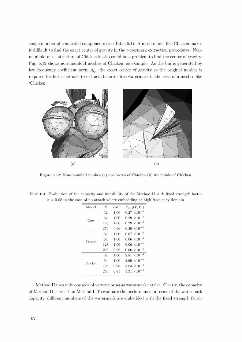
single number of connected components (see Table 6.1). A mesh model like Chicken makesit difficult to find the exact center of gravity in the watermark extraction procedures. Non-manifold mesh structure of Chicken is also could be a problem to find the center of gravity.Fig. 6.12 shows non-manifold meshes of Chicken, as example. As the bin is generated bylow frequency coefficient norm µlρ , the exact center of gravity as the original meshes isrequired for both methods to extract the error-free watermark in the case of a meshes like‘Chicken’.
(a) (b)
Figure 6.12: Non-manifold meshes (a) eye-brows of Chicken (b) inner side of Chicken
Table 6.4: Evaluation of the capacity and invisibility of the Method II with fixed strength factorα = 0.08 in the case of no attack where embedding at high frequency domain
Model N corr Eavg(V, V ′)
Cow
32 1.00 0.27 ×10⁻⁴
64 1.00 0.29 ×10⁻⁴
128 1.00 0.29 ×10⁻⁴
256 0.96 0.29 ×10⁻⁴
Dance
32 1.00 0.07 ×10⁻⁴
64 1.00 0.06 ×10⁻⁴
128 1.00 0.06 ×10⁻⁴
256 0.99 0.06 ×10⁻⁴
Chicken
32 1.00 2.81 ×10⁻⁴
64 1.00 2.99 ×10⁻⁴
128 0.88 3.83 ×10⁻⁴
256 0.85 3.21 ×10⁻⁴
Method II uses only one axis of vertex norms as watermark carrier. Clearly, the capacityof Method II is less than Method I. To evaluate the performance in terms of the watermarkcapacity, different numbers of the watermark are embedded with the fixed strength factor
102
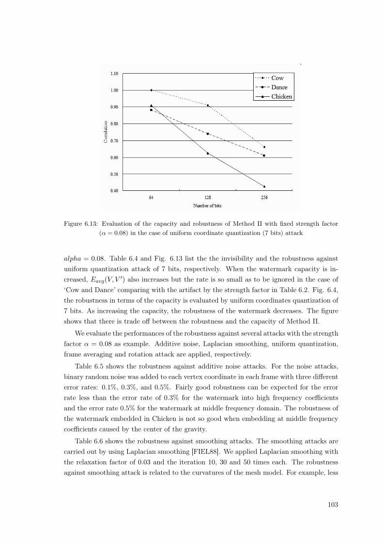
Figure 6.13: Evaluation of the capacity and robustness of Method II with fixed strength factor(α = 0.08) in the case of uniform coordinate quantization (7 bits) attack
alpha = 0.08. Table 6.4 and Fig. 6.13 list the the invisibility and the robustness againstuniform quantization attack of 7 bits, respectively. When the watermark capacity is in-creased, Eavg(V, V ′) also increases but the rate is so small as to be ignored in the case of‘Cow and Dance’ comparing with the artifact by the strength factor in Table 6.2. Fig. 6.4,the robustness in terms of the capacity is evaluated by uniform coordinates quantization of7 bits. As increasing the capacity, the robustness of the watermark decreases. The figureshows that there is trade off between the robustness and the capacity of Method II.
We evaluate the performances of the robustness against several attacks with the strengthfactor α = 0.08 as example. Additive noise, Laplacian smoothing, uniform quantization,frame averaging and rotation attack are applied, respectively.
Table 6.5 shows the robustness against additive noise attacks. For the noise attacks,binary random noise was added to each vertex coordinate in each frame with three differenterror rates: 0.1%, 0.3%, and 0.5%. Fairly good robustness can be expected for the errorrate less than the error rate of 0.3% for the watermark into high frequency coefficientsand the error rate 0.5% for the watermark at middle frequency domain. The robustness ofthe watermark embedded in Chicken is not so good when embedding at middle frequencycoefficients caused by the center of the gravity.
Table 6.6 shows the robustness against smoothing attacks. The smoothing attacks arecarried out by using Laplacian smoothing [FIEL88]. We applied Laplacian smoothing withthe relaxation factor of 0.03 and the iteration 10, 30 and 50 times each. The robustnessagainst smoothing attack is related to the curvatures of the mesh model. For example, less
103
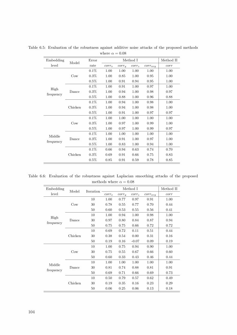
Table 6.5: Evaluation of the robustness against additive noise attacks of the proposed methodswhere α = 0.08
Embeddinglevel
ModelErrorrate
Method I Method IIcorrx corry corrz corravg corr
Highfrequency
Cow0.1% 1.00 1.00 1.00 1.00 1.000.3% 1.00 0.85 1.00 0.95 1.000.5% 1.00 0.91 0.94 0.95 1.00
Dance0.1% 1.00 0.91 1.00 0.97 1.000.3% 1.00 0.94 1.00 0.98 0.970.5% 1.00 0.88 1.00 0.96 0.88
Chicken0.1% 1.00 0.94 1.00 0.98 1.000.3% 1.00 0.94 1.00 0.98 1.000.5% 1.00 0.91 1.00 0.97 0.97
Middlefrequency
Cow0.1% 1.00 1.00 1.00 1.00 1.000.3% 1.00 0.97 1.00 0.99 1.000.5% 1.00 0.97 1.00 0.99 0.97
Dance0.1% 1.00 1.00 1.00 1.00 1.000.3% 1.00 0.91 1.00 0.97 1.000.5% 1.00 0.83 1.00 0.94 1.00
Chicken0.1% 0.66 0.94 0.63 0.74 0.700.3% 0.69 0.91 0.66 0.75 0.830.5% 0.85 0.91 0.59 0.78 0.85
Table 6.6: Evaluation of the robustness against Laplacian smoothing attacks of the proposedmethods where α = 0.08
Embeddinglevel
Model IterationMethod I Method II
corrx corry corrz corravg corr
Highfrequency
Cow10 1.00 0.77 0.97 0.91 1.0030 0.78 0.55 0.77 0.70 0.4450 0.60 0.53 0.55 0.56 0.41
Dance10 1.00 0.94 1.00 0.98 1.0030 0.97 0.80 0.84 0.87 0.9450 0.75 0.75 0.66 0.72 0.72
Chicken10 0.69 0.72 0.11 0.51 0.4430 0.38 0.54 0.00 0.31 0.1650 0.19 0.16 -0.07 0.09 0.19
Middlefrequency
Cow10 1.00 0.75 0.94 0.90 1.0030 0.75 0.55 0.67 0.66 0.6050 0.60 0.33 0.43 0.46 0.44
Dance10 1.00 1.00 1.00 1.00 1.0030 0.81 0.74 0.88 0.81 0.9150 0.69 0.71 0.66 0.69 0.73
Chicken10 0.50 0.79 0.57 0.62 0.4930 0.19 0.35 0.16 0.23 0.2950 0.06 0.25 0.06 0.13 0.18
104
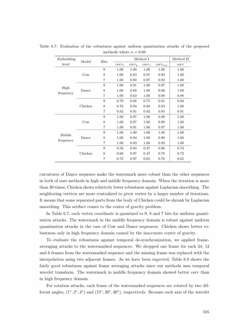
Table 6.7: Evaluation of the robustness against uniform quantization attacks of the proposedmethods where α = 0.08
Embeddinglevel
Model BitsMethod I Method II
corrx corry corrz corravg corr
Highfrequency
Cow9 1.00 1.00 1.00 1.00 1.008 1.00 0.83 0.97 0.93 1.007 1.00 0.80 0.97 0.92 1.00
Dance9 1.00 0.91 1.00 0.97 1.008 1.00 0.88 1.00 0.96 1.007 1.00 0.63 1.00 0.88 0.88
Chicken9 0.79 0.88 0.75 0.81 0.948 0.76 0.94 0.80 0.83 1.007 0.82 0.91 0.82 0.85 0.91
Middlefrequency
Cow9 1.00 0.97 1.00 0.99 1.008 1.00 0.97 1.00 0.99 1.007 1.00 0.91 1.00 0.97 1.00
Dance9 1.00 1.00 1.00 1.00 1.008 1.00 0.94 1.00 0.98 1.007 1.00 0.83 1.00 0.94 1.00
Chicken9 0.56 0.94 0.47 0.66 0.748 0.66 0.97 0.47 0.70 0.727 0.72 0.97 0.65 0.78 0.65
curvatures of Dance sequence make the watermark more robust than the other sequencesin both of ours methods in high and middle frequency domain. When the iteration is morethan 30 times, Chicken shows relatively lower robustness against Laplacian smoothing. Theneighboring vertices are more centralized to pivot vertex by a larger number of iterations.It means that some separated parts from the body of Chicken could be shrunk by Laplaciansmoothing. This artifact comes to the center of gravity problem.
In Table 6.7, each vertex coordinate is quantized to 9, 8 and 7 bits for uniform quanti-zation attacks. The watermark in the middle frequency domain is robust against uniformquantization attacks in the case of Cow and Dance sequences. Chicken shows better ro-bustness only in high frequency domain caused by the inaccurate center of gravity.
To evaluate the robustness against temporal de-synchronization, we applied frame-averaging attacks to the watermarked sequences. We dropped one frame for each 24, 12and 6 frames from the watermarked sequence and the missing frame was replaced with theinterpolation using two adjacent frames. As we have been expected, Table 6.8 shows thefairly good robustness against frame averaging attacks since our methods uses temporalwavelet transform. The watermark in middle frequency domain showed better corr thanin high frequency domain.
For rotation attacks, each frame of the watermarked sequences are rotated by two dif-ferent angles, (1◦, 2◦, 3◦) and (15◦, 20◦, 30◦), respectively. Because each axis of the wavelet
105
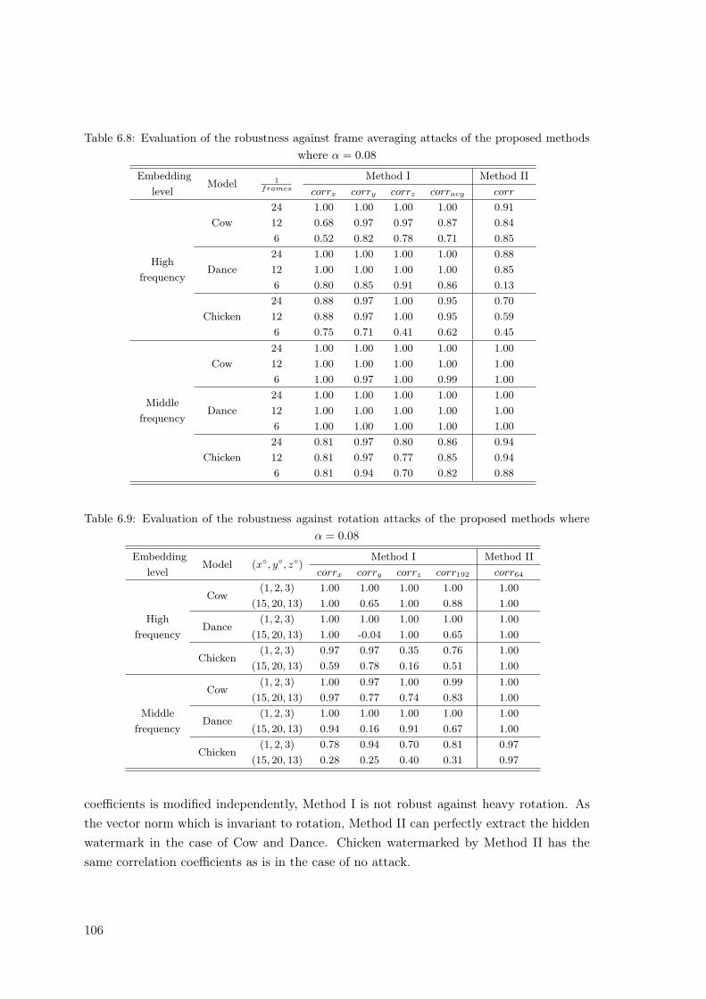
Table 6.8: Evaluation of the robustness against frame averaging attacks of the proposed methodswhere α = 0.08
Embeddinglevel
Model 1frames
Method I Method IIcorrx corry corrz corravg corr
Highfrequency
Cow24 1.00 1.00 1.00 1.00 0.9112 0.68 0.97 0.97 0.87 0.846 0.52 0.82 0.78 0.71 0.85
Dance24 1.00 1.00 1.00 1.00 0.8812 1.00 1.00 1.00 1.00 0.856 0.80 0.85 0.91 0.86 0.13
Chicken24 0.88 0.97 1.00 0.95 0.7012 0.88 0.97 1.00 0.95 0.596 0.75 0.71 0.41 0.62 0.45
Middlefrequency
Cow24 1.00 1.00 1.00 1.00 1.0012 1.00 1.00 1.00 1.00 1.006 1.00 0.97 1.00 0.99 1.00
Dance24 1.00 1.00 1.00 1.00 1.0012 1.00 1.00 1.00 1.00 1.006 1.00 1.00 1.00 1.00 1.00
Chicken24 0.81 0.97 0.80 0.86 0.9412 0.81 0.97 0.77 0.85 0.946 0.81 0.94 0.70 0.82 0.88
Table 6.9: Evaluation of the robustness against rotation attacks of the proposed methods whereα = 0.08
Embeddinglevel
Model (x◦, y◦, z◦)Method I Method II
corrx corry corrz corr192 corr64
Highfrequency
Cow(1, 2, 3) 1.00 1.00 1.00 1.00 1.00
(15, 20, 13) 1.00 0.65 1.00 0.88 1.00
Dance(1, 2, 3) 1.00 1.00 1.00 1.00 1.00
(15, 20, 13) 1.00 -0.04 1.00 0.65 1.00
Chicken(1, 2, 3) 0.97 0.97 0.35 0.76 1.00
(15, 20, 13) 0.59 0.78 0.16 0.51 1.00
Middlefrequency
Cow(1, 2, 3) 1.00 0.97 1.00 0.99 1.00
(15, 20, 13) 0.97 0.77 0.74 0.83 1.00
Dance(1, 2, 3) 1.00 1.00 1.00 1.00 1.00
(15, 20, 13) 0.94 0.16 0.91 0.67 1.00
Chicken(1, 2, 3) 0.78 0.94 0.70 0.81 0.97
(15, 20, 13) 0.28 0.25 0.40 0.31 0.97
coefficients is modified independently, Method I is not robust against heavy rotation. Asthe vector norm which is invariant to rotation, Method II can perfectly extract the hiddenwatermark in the case of Cow and Dance. Chicken watermarked by Method II has thesame correlation coefficients as is in the case of no attack.
106
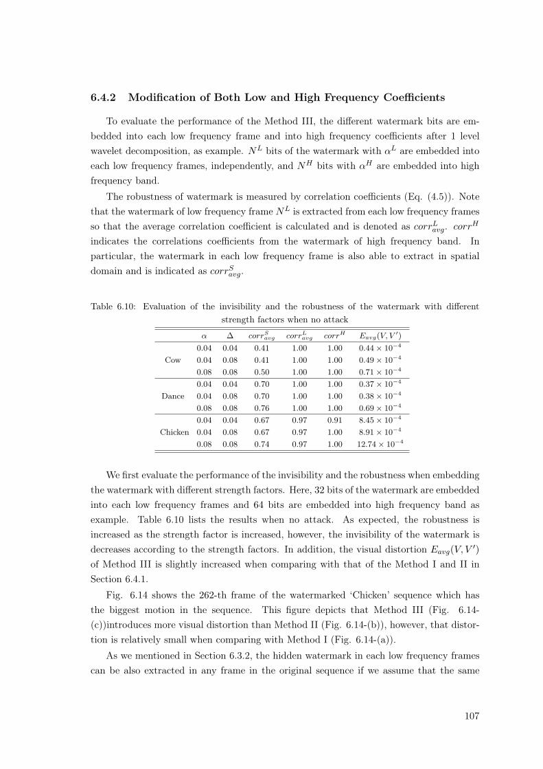
6.4.2 Modification of Both Low and High Frequency Coefficients
To evaluate the performance of the Method III, the different watermark bits are em-bedded into each low frequency frame and into high frequency coefficients after 1 levelwavelet decomposition, as example. NL bits of the watermark with αL are embedded intoeach low frequency frames, independently, and NH bits with αH are embedded into highfrequency band.
The robustness of watermark is measured by correlation coefficients (Eq. (4.5)). Notethat the watermark of low frequency frame NL is extracted from each low frequency framesso that the average correlation coefficient is calculated and is denoted as corrL
avg. corrH
indicates the correlations coefficients from the watermark of high frequency band. Inparticular, the watermark in each low frequency frame is also able to extract in spatialdomain and is indicated as corrS
avg.
Table 6.10: Evaluation of the invisibility and the robustness of the watermark with differentstrength factors when no attack
α ∆ corrSavg corrL
avg corrH Eavg(V, V ′)
Cow0.04 0.04 0.41 1.00 1.00 0.44× 10⁻⁴
0.04 0.08 0.41 1.00 1.00 0.49× 10⁻⁴
0.08 0.08 0.50 1.00 1.00 0.71× 10⁻⁴
Dance0.04 0.04 0.70 1.00 1.00 0.37× 10⁻⁴
0.04 0.08 0.70 1.00 1.00 0.38× 10⁻⁴
0.08 0.08 0.76 1.00 1.00 0.69× 10⁻⁴
Chicken0.04 0.04 0.67 0.97 0.91 8.45× 10⁻⁴
0.04 0.08 0.67 0.97 1.00 8.91× 10⁻⁴
0.08 0.08 0.74 0.97 1.00 12.74× 10⁻⁴
We first evaluate the performance of the invisibility and the robustness when embeddingthe watermark with different strength factors. Here, 32 bits of the watermark are embeddedinto each low frequency frames and 64 bits are embedded into high frequency band asexample. Table 6.10 lists the results when no attack. As expected, the robustness isincreased as the strength factor is increased, however, the invisibility of the watermark isdecreases according to the strength factors. In addition, the visual distortion Eavg(V, V ′)of Method III is slightly increased when comparing with that of the Method I and II inSection 6.4.1.
Fig. 6.14 shows the 262-th frame of the watermarked ‘Chicken’ sequence which hasthe biggest motion in the sequence. This figure depicts that Method III (Fig. 6.14-(c))introduces more visual distortion than Method II (Fig. 6.14-(b)), however, that distor-tion is relatively small when comparing with Method I (Fig. 6.14-(a)).
As we mentioned in Section 6.3.2, the hidden watermark in each low frequency framescan be also extracted in any frame in the original sequence if we assume that the same
107
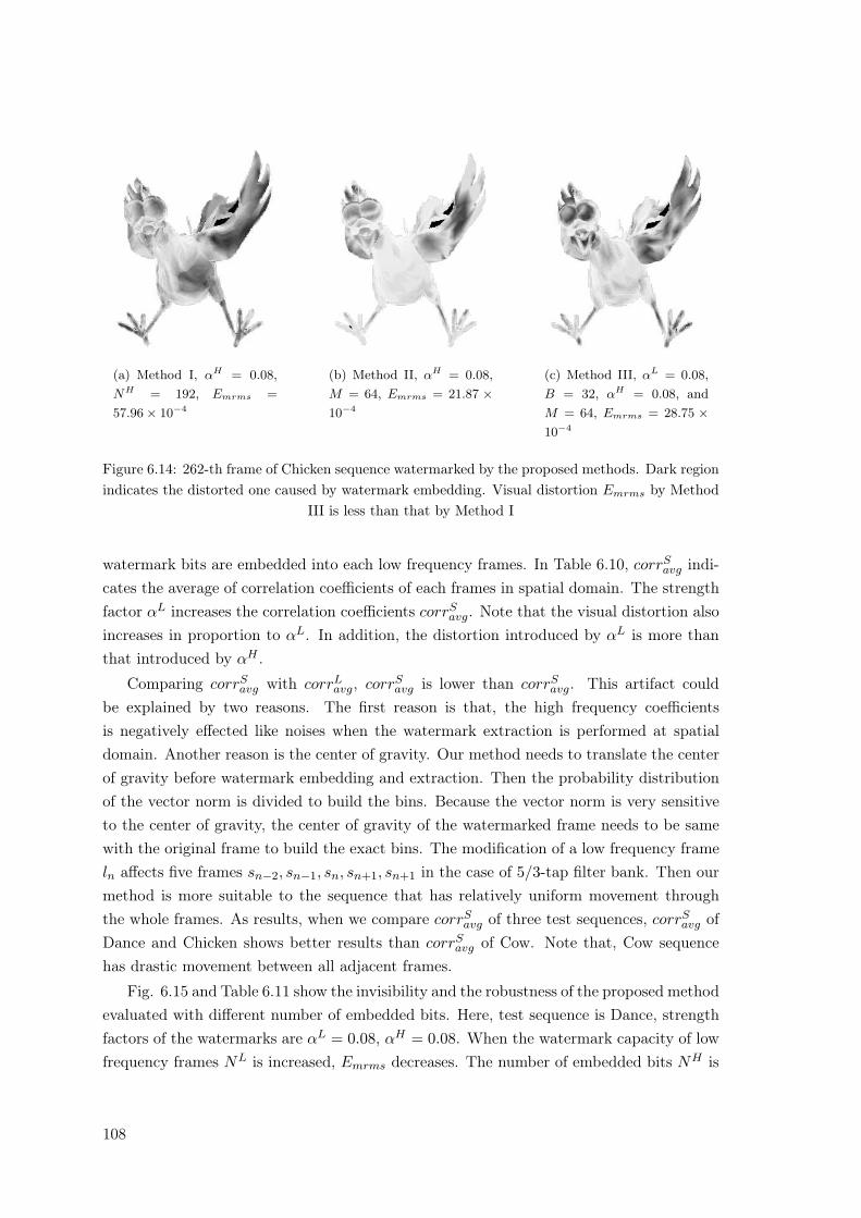
(a) Method I, αH = 0.08,NH = 192, Emrms =
57.96× 10⁻⁴
(b) Method II, αH = 0.08,M = 64, Emrms = 21.87 ×10⁻⁴
(c) Method III, αL = 0.08,B = 32, αH = 0.08, andM = 64, Emrms = 28.75 ×10⁻⁴
Figure 6.14: 262-th frame of Chicken sequence watermarked by the proposed methods. Dark regionindicates the distorted one caused by watermark embedding. Visual distortion Emrms by Method
III is less than that by Method I
watermark bits are embedded into each low frequency frames. In Table 6.10, corrSavg indi-
cates the average of correlation coefficients of each frames in spatial domain. The strengthfactor αL increases the correlation coefficients corrS
avg. Note that the visual distortion alsoincreases in proportion to αL. In addition, the distortion introduced by αL is more thanthat introduced by αH .
Comparing corrSavg with corrL
avg, corrSavg is lower than corrS
avg. This artifact couldbe explained by two reasons. The first reason is that, the high frequency coefficientsis negatively effected like noises when the watermark extraction is performed at spatialdomain. Another reason is the center of gravity. Our method needs to translate the centerof gravity before watermark embedding and extraction. Then the probability distributionof the vector norm is divided to build the bins. Because the vector norm is very sensitiveto the center of gravity, the center of gravity of the watermarked frame needs to be samewith the original frame to build the exact bins. The modification of a low frequency frameln affects five frames sn−2, sn−1, sn, sn+1, sn+1 in the case of 5/3-tap filter bank. Then ourmethod is more suitable to the sequence that has relatively uniform movement throughthe whole frames. As results, when we compare corrS
avg of three test sequences, corrSavg of
Dance and Chicken shows better results than corrSavg of Cow. Note that, Cow sequence
has drastic movement between all adjacent frames.
Fig. 6.15 and Table 6.11 show the invisibility and the robustness of the proposed methodevaluated with different number of embedded bits. Here, test sequence is Dance, strengthfactors of the watermarks are αL = 0.08, αH = 0.08. When the watermark capacity of lowfrequency frames NL is increased, Emrms decreases. The number of embedded bits NH is
108
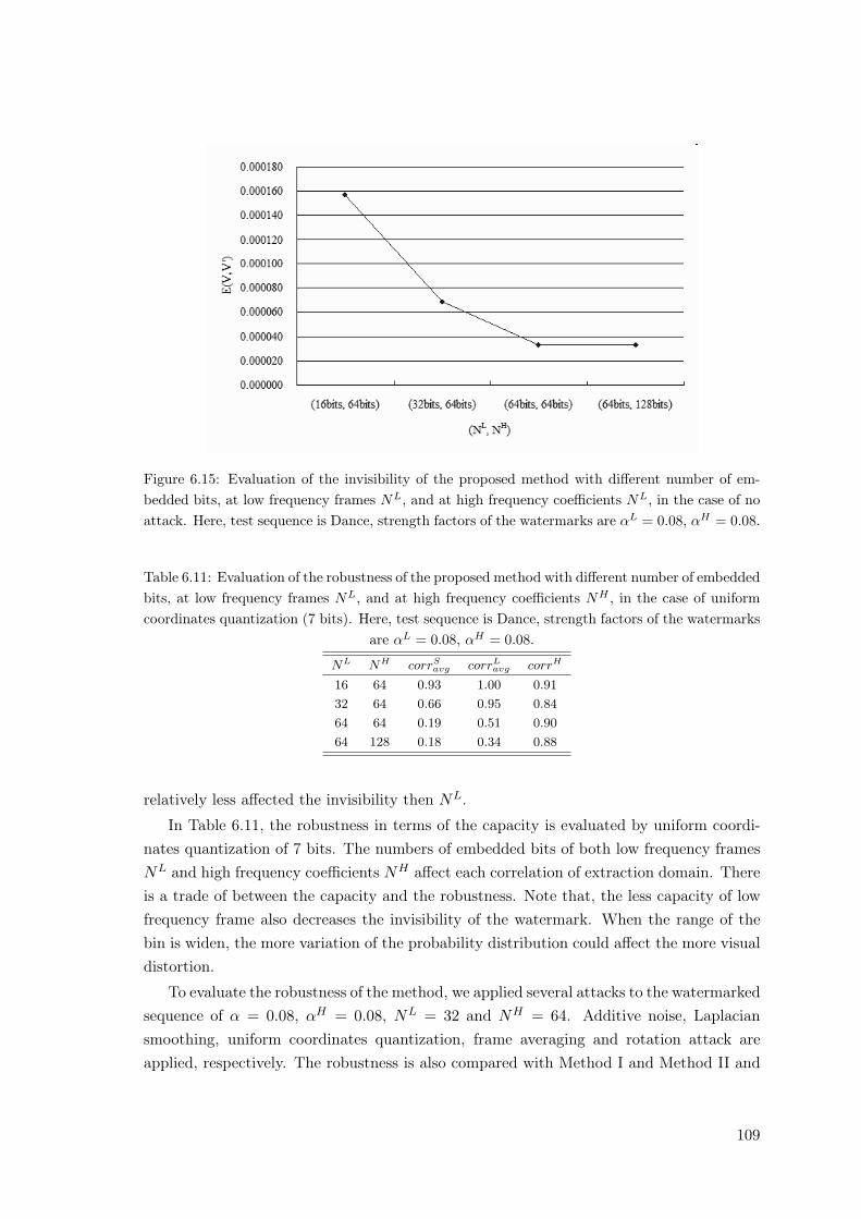
Figure 6.15: Evaluation of the invisibility of the proposed method with different number of em-bedded bits, at low frequency frames NL, and at high frequency coefficients NL, in the case of noattack. Here, test sequence is Dance, strength factors of the watermarks are αL = 0.08, αH = 0.08.
Table 6.11: Evaluation of the robustness of the proposed method with different number of embeddedbits, at low frequency frames NL, and at high frequency coefficients NH , in the case of uniformcoordinates quantization (7 bits). Here, test sequence is Dance, strength factors of the watermarks
are αL = 0.08, αH = 0.08.
NL NH corrSavg corrL
avg corrH
16 64 0.93 1.00 0.9132 64 0.66 0.95 0.8464 64 0.19 0.51 0.9064 128 0.18 0.34 0.88
relatively less affected the invisibility then NL.
In Table 6.11, the robustness in terms of the capacity is evaluated by uniform coordi-nates quantization of 7 bits. The numbers of embedded bits of both low frequency framesNL and high frequency coefficients NH affect each correlation of extraction domain. Thereis a trade of between the capacity and the robustness. Note that, the less capacity of lowfrequency frame also decreases the invisibility of the watermark. When the range of thebin is widen, the more variation of the probability distribution could affect the more visualdistortion.
To evaluate the robustness of the method, we applied several attacks to the watermarkedsequence of α = 0.08, αH = 0.08, NL = 32 and NH = 64. Additive noise, Laplaciansmoothing, uniform coordinates quantization, frame averaging and rotation attack areapplied, respectively. The robustness is also compared with Method I and Method II and
109
Table 6.12: Evaluation of the robustness against additive noise where the numbers of the embeddedbits are NL = 32 and M = 64 and the strength factors are αL = 0.08 and αH = 0.08.
Model Error rateMethod III Method I Method II
corrSavg corrL
avg corrH corr192 corr64
Cow0.3% 0.41 0.90 1.00 0.95 1.000.5% 0.21 0.70 0.97 0.95 1.00
Dance0.3% 0.75 0.97 0.87 0.98 0.970.5% 0.65 0.93 0.91 0.96 0.88
Chicken0.3% 0.63 0.85 0.97 0.98 1.000.5% 0.48 0.72 0.90 0.98 1.00
Table 6.13: Evaluation of the robustness against Laplacian smoothing where the number of theembedded bits are NL = 32 and NH = 64, strength factors are αL = 0.08 and αH = 0.08.
Model IterationMethod III Method I Method II
corrSavg corrL
avg corrH corr192 corr64
Cow30 0.05 0.14 0.78 0.70 0.4450 0.00 -0.01 0.61 0.56 0.41
Dance30 0.51 0.71 1.00 0.87 0.9450 0.32 0.45 0.87 0.72 0.72
Chicken30 -0.05 -0.05 0.29 0.31 0.1650 -0.05 -0.06 0.11 0.09 0.19
denoted as corr192 and corr62 where the subscript means the number of embedded bits.Note that, the capacity of the proposed method is NL × 1
2(thenumberofframes) + NH
bits.
Table 6.12 shows the robustness against additive noise attacks. For the noise attacks,binary random noise was added to each vertex coordinate in each frame with three differenterror rates: 0.3%, and 0.5%. Here, the error rate represents the amplitude of noise as afraction of the maximum vertex norm of the object. Both corrL
avg and corrHavg shows fairly
good robustness against additive noise attack while embedding much more capacity thanMethod I and Method II.
Table 6.12 shows the robustness against smoothing attacks. The smoothing attacksare carried out by using Laplacian smoothing with the relaxation factor of 0.03 and theiteration 30 and 50 times each. Since the robustness against smoothing attack is related tothe curvatures of the mesh model, Dance sequence is more robust than the other sequences.When corrH
avg is compared with Method I and Method II, the proposed method showedbetter robustness against Laplacian smoothing attack since the proposed method generatethe bins from the average frame of the watermarked low frequency frames. In addition, thewatermark in the high frequency coefficients is more robust against than the watermark inlow frequency frame in the case of Cow and Dance sequence. However, the center of gravity
110
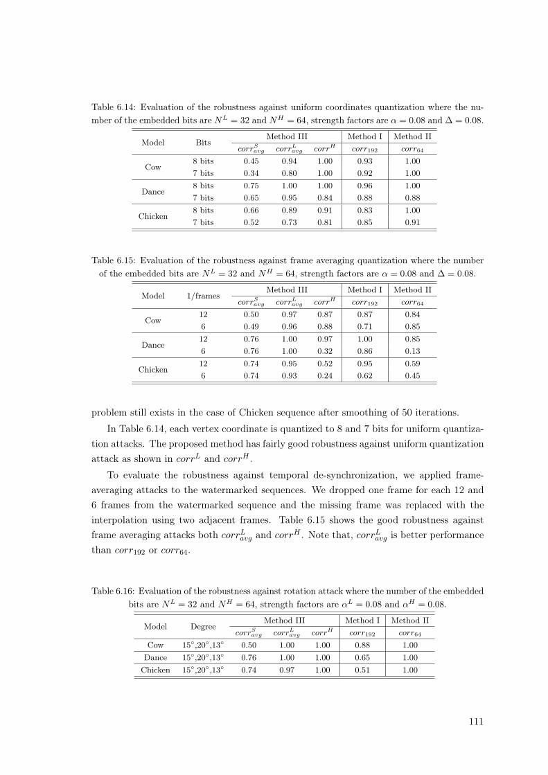
Table 6.14: Evaluation of the robustness against uniform coordinates quantization where the nu-mber of the embedded bits are NL = 32 and NH = 64, strength factors are α = 0.08 and ∆ = 0.08.
Model BitsMethod III Method I Method II
corrSavg corrL
avg corrH corr192 corr64
Cow8 bits 0.45 0.94 1.00 0.93 1.007 bits 0.34 0.80 1.00 0.92 1.00
Dance8 bits 0.75 1.00 1.00 0.96 1.007 bits 0.65 0.95 0.84 0.88 0.88
Chicken8 bits 0.66 0.89 0.91 0.83 1.007 bits 0.52 0.73 0.81 0.85 0.91
Table 6.15: Evaluation of the robustness against frame averaging quantization where the numberof the embedded bits are NL = 32 and NH = 64, strength factors are α = 0.08 and ∆ = 0.08.
Model 1/framesMethod III Method I Method II
corrSavg corrL
avg corrH corr192 corr64
Cow12 0.50 0.97 0.87 0.87 0.846 0.49 0.96 0.88 0.71 0.85
Dance12 0.76 1.00 0.97 1.00 0.856 0.76 1.00 0.32 0.86 0.13
Chicken12 0.74 0.95 0.52 0.95 0.596 0.74 0.93 0.24 0.62 0.45
problem still exists in the case of Chicken sequence after smoothing of 50 iterations.
In Table 6.14, each vertex coordinate is quantized to 8 and 7 bits for uniform quantiza-tion attacks. The proposed method has fairly good robustness against uniform quantizationattack as shown in corrL and corrH .
To evaluate the robustness against temporal de-synchronization, we applied frame-averaging attacks to the watermarked sequences. We dropped one frame for each 12 and6 frames from the watermarked sequence and the missing frame was replaced with theinterpolation using two adjacent frames. Table 6.15 shows the good robustness againstframe averaging attacks both corrL
avg and corrH . Note that, corrLavg is better performance
than corr192 or corr64.
Table 6.16: Evaluation of the robustness against rotation attack where the number of the embeddedbits are NL = 32 and NH = 64, strength factors are αL = 0.08 and αH = 0.08.
Model DegreeMethod III Method I Method II
corrSavg corrL
avg corrH corr192 corr64
Cow 15◦,20◦,13◦ 0.50 1.00 1.00 0.88 1.00Dance 15◦,20◦,13◦ 0.76 1.00 1.00 0.65 1.00Chicken 15◦,20◦,13◦ 0.74 0.97 1.00 0.51 1.00
111
The proposed method is also robust against rotation attacks. The center of gravityproblem of Chicken is able to result in corrL
avg = 0.97, however, the error-free watermarkextraction is possible in the case of Cow and Dance in terms of both corrL and corrH .
6.5 Conclusions
In this chapter, we proposed blind watermarking methods for 3-D mesh sequences.To be robust against various attacks such as spatial and temporal attacks, our methodsuse temporal wavelet transform. Two methods are introduced. The first method directlyembeds the watermark into each axis of wavelet coefficients, and the second method intotheir vector norm. To increase the capacity of the watermark bits to be embedded, we dividethe bins by using low frequency coefficients which are less sensitive to several attacks. Asthe vertices with the identical connectivity index over whole frames belong to one bin,their high frequency coefficients are also assigned into the same bin. For embedding awatermark, we modify the variance of wavelet coefficients in high (or middle) frequencyband. The distribution of temporal wavelet coefficients can be approximated to Laplaciandistribution which concentrates on zero mean. The high frequency coefficients in each bincan be divided by two groups according to the sign of the high frequency coefficient. Toembed the watermark bit +1 (or −1), the variance of positive group is changed relativelybigger (or smaller) than negative group.
Two methods are introduced. Each method has focused on the capacity and invisibility,respectively. To increase the capacity of watermark, The first method modifies the varianceof the distribution from temporal wavelet coefficients of each axis, independently. The otherchanges the second moment of the distribution of the temporal wavelet coefficients of vertexnorms for better invisibility of the watermark and the robustness against rotation attacks.
From the modification method of high frequency coefficients of vertex norms, we proposethe watermarking method by modifying the distribution of both low and high frequencycoefficients. The method utilized our previous methods introduced in Chapter 5 and inChapter 6.3.1. The method utilized variance shifting method in Chapter 5 to embed thewatermark into each low frequency frames. The distribution of temporally high frequencycoefficients of the vector norm is modified by the method in Chapter 6.3.1.
We showed that the proposed methods are fairly robust against various attacks thatare probably concerned in copyright protection of 3-D mesh sequences. In particular, wealso showed that the watermark in low frequency could be the complement of the previousmethods in Chapter 6.3.1 to improve the capacity and the robustness. The extraction ofthe watermark which is embedded in each low frequency frame is also possible in spatialdomain without temporal wavelet transform. This is one of the attractive properties of ourmethod, however, the performance needs to be improved by considering the artifact by thehigh frequency coefficients and the filter-bank choice for temporal wavelet transform.
112

Our method does not require the original mesh sequence. The hidden watermark bitcan be easily retrieved by simple comparison between the second moment of positive groupand of negative group.
113

114
Chapter 7
General Conclusions andPerspectives
In this thesis, we have proposed wavelet transform based digital watermarking methodsfor 3-D surface meshes and mesh sequences for the application of copy-right protection.
The performance of the digital watermarking method is determined by the watermarkembedding primitive and the hiding technique. Although wavelet transform needs morecomputational time for watermark embedding and extraction process, it provides severaladvantages in terms of invisibility, capacity and robustness against attacks.
In the first part of the thesis, we introduced two watermarking methods for 3-D trian-gular surface meshes based on multiresolution wavelet analysis.
In Chapter 4, we proposed a robust blind watermarking method for 3-D triangularsurface meshes. In the previous works, [KANA98] embeds the watermark into the waveletcoefficient vector in a certain order, they have to use the original mesh to re-orient the topo-logical synchronization of the vertices. An extended work [UCCH04] is introduced for theblind detection, but their methods are limited to the input mesh with regular subdivisionconnectivity as was in [KANA98]. By using irregular wavelet analysis scheme, our pro-posal can be applied to irregular as well as regular meshes without re-meshing. To recoverthe topological information after inverse wavelet transform, vertex re-ordering algorithmis used as a pre-processing for forward wavelet transform and a post-processing for inversewavelet transform. The watermarks which are embedded into the wavelet coefficients arevisually imperceptible while having the good robustness against geometrical attacks anddistortion-less attacks. Through the simulation results, we proved that the vertex andface re-ordering procedure as pre-processing for both watermark embedding and extrac-tion makes our method be robust against connectivity reordering attacks. We also showedthat multiresolution embedding has more capacity while keeping the robustness againstconnectivity reordering as well as geometrical attacks. However, the watermark which isembedded into the wavelet coefficients in a certain order by spread spectrum method can
115
not be retrieved after connectivity information is destroyed by topological attacks. For therobustness against topological attacks, pre-processing such as registration and re-samplingis required as in [PRAU99, YIN01], or the robustness against topological attacks cannotbe guaranteed [KANA98, UCCH04, KIM05].
In Chapter 5, we developed a blind watermarking method which is robust againsttopological attacks. As previous wavelet analysis based 3-D mesh watermarking methods[KANA98, UCCH04, KIM05] embed the watermark information into wavelet coefficientsarranged in a certain order, statistical features of scale coefficients on approximated meshesare used as a watermark carrier [KIM06b, KIM06a]. The statistical features might be lesssensitive than the scale (or wavelet) coefficients themselves in a certain order. The proposedmethods modify the distribution of scale coefficients to embed the watermark. As the nu-mber of scale coefficients decreases after wavelet analysis, our methods are more applicableto relatively large models. The watermark extraction is able to be done directly from ver-tex norms in spatial domain. We do not use wavelet analysis in the watermark detection.Then, it is not necessary to use any pre-processing such as registration, re-sampling andre-ordering for wavelet analysis in the process of watermark detection. Furthermore, thetechnique can reduce drastically the computational complexity and processing time. Whilethis technique can slightly decrease the robustness against geometrical attacks, it allowsour methods to be robust against topological attacks. Assuming that the distribution ofeach bin can be approximated uniform distribution, the mean or variance of the uniformdistribution is modified by histogram mapping function. As the watermark detection pro-cess does not require wavelet analysis or any pre-processing, the embedded watermark canbe simply calculate the mean or variance of each bin. Through simulations, we proved thatthe proposed has fairly good performance in terms of the watermark transparency and ro-bustness against various attacks. Even though the proposed methods are not highly robust,our attempts demonstrate a possibility, blind watermarking based on wavelet analysis for3-D mesh model.
In the second part of the thesis, we have presented digital watermarking methods formesh sequence based 3-D animation using temporal wavelet transform.
In Chapter 6, we presented watermarking methods for 3-D mesh sequences. The mainidea is to transform coordinates of vertex with the identical connectivity index along tem-poral axis using wavelet transform and to use the distribution of wavelet coefficients. Thewavelet (high frequency) coefficients from temporal wavelet transform can be approximatedto Laplacian probability density function with symmetric property. Then we modify thedistribution of high frequency coefficients by histogram mapping function. We change thevariance of high (or middle) frequency coefficients according to the watermark bit. Due tothe use of the distribution, our method can retrieve the hidden watermark without any in-formation about original mesh sequences in the process of watermark detection. All verticesare divided into groups, namely bins, using the distribution of low-frequency coefficients.
116
As the vertices with the identical connectivity index over whole frames belong to one bin,their high frequency coefficients are also assigned into the same bin. Then, the watermarkis embedded into each axis of the high frequency coefficients or into the vector norms ofthe high frequency coefficients. The methods generates bins from the average frame of lowfrequency frames and modify the second moment of the probability distribution of highfrequency coefficients in the bin. The robustness and the capacity of the methods could beincreased by the number of total frames, and the number of vertices of the frame as well asthe regularity of the vertices for computing the center of gravity. Through simulations weshow that the proposed is fairly robust against various attacks that are probably concernedin copyright protection of 3-D mesh sequences.
In Chapter 6, we have also presented another watermarking method for 3-D mesh se-quences. From the property of the wavelet decomposition, the method modifies both lowand high frequency coefficients after temporal wavelet transform to increase the robust-ness and the capacity of the watermark to be embedded. For each low frequency frames,we modify the variance of the distribution of vertex norms by the method introduced inChapter 5. We also modify the distribution of temporally high frequency coefficients bythe second method in Chapter 6. We showed that the watermark in low frequency could bethe complement of the first and second method to improve the capacity and the robustness.The extraction of the watermark which is embedded in each low frequency frame is alsopossible in spatial domain without temporal wavelet transform. This is one of attractiveproperties of our method, however, the performance needs to be improved by consider-ing the artifact by the high frequency coefficients and the filter-bank choice for temporalwavelet transform.
Several directions for future work remain open. Since the proposed methods are eval-uated on only a few meshes, it would be interesting to know the behavior of the proposedmethods when they are applied to larger diversity of 3-D models as those available in verydifferent areas, for example, CAD models, 3D laser scanning, terrain modeling, moleculedesign, 3D volume triangulation for numerical simulation, and so on. In addition, therobustness against clipping attacks needs be considered for further research. It would beimproved by using the local distributions of each subpart of the original meshes.
117

118
Bibliography
[ALLI03] P. Alliez and C. Gotsman. Recent advances in compression of 3d meshes, 2003.
[ARNO00] Michael Arnold. Audio watermarking: Features, applications, and algorithms.In IEEE International Conference on Multimedia and Expo (II), pages 1013–1016,2000.
[ASPE02] N. Aspert, D. Santa-Cruz, and T. Ebrahimi. Mesh: Measuring errors betweensurfaces using the hausdorff distance. In Proceedings of the IEEE International Confer-ence on Multimedia and Expo, volume I, pages 705 – 708, 2002. http://mesh.epfl.ch.
[BEND96] W. Bender, D. Gruhl, N. Morimoto, and Aiguo Lu. Techniques for data hiding.IBM Syst. J., vol. 35, no. 3–4, pp. 313–336, 1996.
[BENE99] Oliver Benedens. Geometry-based watermarking of 3d models. IEEE Comput.Graph. Appl., vol. 19, no. 1, pp. 46–55, 1999.
[CAYR03] F. Cayre. Contributions au tatouage des maillages surfacique 3D. PhD thesis,ENST/TSI et UCL/TELE, 2003.
[CHO07] J. W. Cho, R. Prost, and H. Y. Jung. An oblivious watermarking for 3-d polyg-onal meshes using distribution of vertex norms. IEEE Trans. Signal Processing, vol.55, no. 1, pp. 142–155, Jan 2007.
[CHO04] Jae-Won Cho, Min-Su Kim, Rémy Prost, Hyun-Yeol Chung, and Ho-Youl Jung.Robust watermarking on polygonal meshes using distribution of vertex norms. InIngemar J. Cox, Ton Kalker, and Heung-Kyu Lee, editors, IWDW, volume 3304 ofLecture Notes in Computer Science, pages 283–293. Springer, 2004.
[CHO06] J.W. Cho, M.S. Kim, S. Valette, H.Y. Jung, and R. Prost. 3-d dynamic meshcompression using wavelet-based multiresolution analysis. In Proceedings of ICIP 2006,pages 529–532, october 2006.
[CIGN98] P. Cignoni, C. Rocchini, and R. Scopigno. Metro: Measuring error on simplifiedsurfaces. Computer Graphics Forum, vol. 17, no. 2, pp. 167–174, 1998.
119
[COX97] I. Cox, J. Kilian, T. Leighton, and T. Shamoon. Secure spread spectrum water-marking for multimedia. IEEE Trans. Image Processing, vol. 6, no. 12, pp. 1673–1687,1997.
[COX02] I. Cox, M. L. Miller, and J. A. Bloom. Digital watermarking. Morgan KaufmannPublishers Inc., San Francisco, CA, USA, 2002.
[CRAV97] Scott Craver, Nasir D. Memon, Boon-Lock Yeo, and Minerva M. Yeung. Caninvisible watermarks resolve rightful ownerships? In Storage and Retrieval for Imageand Video Databases (SPIE), pages 310–321, 1997.
[DCI] Digital Cinema System Specification V1.0, Final Approval July 20,2005, Digital Cinema Initiatives, LLC Member Representatives Committee.http://www.dcimovies.com/DCI_Digital_Cinema_System_Spec_v1.pdf.
[CIFE] CineFence, Royal Philips Electronics. http://www.business-sites.philips.com.
[FIEL88] D.A. Field. Laplacian smoothing and delaunay triangulation. Communicationand Applied Numerical Methods, vol. 4, pp. 709–712, 1988.
[FREY99] P.J. Frey and P.L. George. Maillages: application aux methodes d’elements finis.Hermes, Paris, France, 1999.
[FRID01] J. Fridrich, M. Goljan, and R. Du. Invertible authentication. In In Proceedingsof the SPIE vol. 3971, Security and Watermarking of Multimedia Contents III, pages197–208, 2001.
[FRID02] J. Fridrich, M. Goljan, and R. Du. Lossless data embedding–new paradigm indigital watermarking. EURASIP J. Appl. Signal. Process., no. 2, pp. 185–196, 2002.
[GARL97] M. Garland and P. S. Heckbert. Surface simplification using quadric errormetrics. In SIGGRAPH ’97, pages 209–216, New York, NY, USA, 1997. ACMPress/Addison-Wesley Publishing Co.
[GONZ92] R. Gonzalez and R. Woods. Digital Image Processing, pages 518–548. Addison-Wesley Publishing Company, 1992.
[GRUH96] Daniel Gruhl, Anthony Lu, and Walter Bender. Echo hiding. In InformationHiding, pages 293–315, 1996.
[GUSK04] Igor Guskov and Andrei Khodakovsky. Wavelet compression of parametri-cally coherent mesh sequences. In SCA ’04: Proceedings of the 2004 ACM SIG-GRAPH/Eurographics symposium on Computer animation, pages 183–192, New York,NY, USA, 2004. ACM Press.
120
[HART98] F. Hartung and B. Girod. Watermarking of uncompressed and compressedvideo. Signal Processing, vol. 66, no. 3, pp. 283–301, 1998.
[HERO03] Herodotus. The Histories (Penguin Classics). Penguin Classics, ISBN0140449086, April 2003.
[HIST] Michaele Stewart. People, Places Things: Histiaeus, GreekMythology: From the Iliad to the Fall of the Last Tyrant.http://messagenet.com/myths/ppt/Histiaeus_1.html.
[HORM02] K. Hormann. An easy way of detecting subdivision connectivity in a trianglemesh. Technical Report 3, Department of Computer Science 9, University of Erlangen,May 2002.
[IBAR03] Lawrence Ibarria and Jarek Rossignac. Dynapack: space-time compression of the3d animations of triangle meshes with fixed connectivity. In SCA ’03: Proceedings ofthe 2003 ACM SIGGRAPH/Eurographics symposium on Computer animation, pages126–135, Aire-la-Ville, Switzerland, Switzerland, 2003. Eurographics Association.
[KALI03] A. Kalivas, A. Tefas, and I. Pitas. Watermarking of 3d models using principalcomponent analysis. In Acoustics, Speech, and Signal Processing, 2003. Proceedings.(ICASSP ’03). 2003 IEEE International Conference on, volume 5, pages 676–679,2003.
[KANA98] S. Kanai, D. Date, and T. Kishinami. Digital watermarking for 3d polygonusing multiresolution wavelet decomposition. In Proc. Sixth IFIP WG 5.2 GEO-6,pages 296–307, Tokyo, Japan, December 1998.
[KARN00] Zachi Karni and Craig Gotsman. Spectral compression of mesh geometry. InKurt Akeley, editor, Siggraph 2000, Computer Graphics Proceedings, pages 279–286.ACM Press / ACM SIGGRAPH / Addison Wesley Longman, 2000.
[KEJA03] Arun Kejariwal. Watermarking. IEEE Potentials, Oct./Nov.:37–40, 2003.
[KIM02] Min-Su Kim. A Study on Digital Video Watermarking based on Discrete WaveletTransform. Master’s thesis, Department of Information & Communication Engneering,Yeungnam University, 2002.
[KIM05] M. S. Kim, S. Valette, H. Y. Jung, and R. Prost. Watermarking of 3d irregularmeshes based on wavelet multiresolution analysis. Lecture Notes in Computer Science,vol. 3710, pp. 313–324, September 2005.
[KIM06a] M.S. Kim, J.W. Cho, R. Prost, and H.Y. Jung. Wavelet anaysis based blindwatermarking for 3-d surface meshes. In In Proc. of IWDW 2006, volume 5, pages477–480, November 2006.
121
[KIM06b] M.S. Kim, J.W.Cho, H.Y. Jung, and R. Prost. A robust blind watermarkingfor 3d meshes using distribution of scale coefficients in irregular wavelet analysis.In Acoustics, Speech, and Signal Processing, 2006. Proceedings. (ICASSP ’06). 2006IEEE International Conference on, volume 5, pages 477–480, May 2006.
[KIM06c] M.S. Kim, R. Prost, H.Y. Chung, and H.Y. Jung. A blind watermarking for 3-ddynamic mesh model using distribution of temporal wavelet coefficients. In In Proc.of IWMRCS 2006, volume 5, pages 477–480, September 2006.
[KIMT00] Tae-Hoon Kim, Jehee Lee, and Sung Yong Shin. Robust motion watermarkingbased on multiresolution analysis. Comput. Graph. Forum, 19(3):189–198, 2000.
[KOCH96] E. Koch, J. Rindfrey, and J. Zhao. Copyright protection for multimedia data.In In Digital Media and Electronic Publishing, pages 203–213, London, 1996. AcademicPress.
[LANG96] G. C. Langelaar, R. L. Lagendijk, , and J. Biemond. Realtime labeling methodsfor mpeg compressed video. In In Proc. 18th Symp. Information Theory in the Benelux,pp 25–32, 1996.
[LANG97] Gerhard.C Langelaar, J.C.A van der Lubbe, Reginald L. Lagendijk. RobustLabeling Methods for Copy Protection of Images. SPIE-EI’97 - Storage and Retrievalfor Still Images and Video Databases, Feb. 1997. Vol. V No. 3022, pp. 289–309, 1997.
[LEE03] Suk-Hwan Lee, Tae-Su Kim, Byung-Ju Kim, Seong-Geun Kwon, Ki-Ryong Kwon,and Kuhn-Il Lee. 3d polygonal meshes watermarking using normal vector distribu-tions. In Proc. of ICME, pages 105–108, 2003.
[LEE05] Seung-Woo Lee; A. Senot, Ho-Youl Jung and R. Prost. Regularized marchingcubes mesh. Image Processing, 2005. ICIP 2005. IEEE International Conference on.vol.3, pp. 788–791, Sept. 2005.
[LENG99] Jerome Edward Lengyel. Compression of time-dependent geometry. In SI3D’99: Proceedings of the 1999 symposium on Interactive 3D graphics, pages 89–95, NewYork, NY, USA, 1999. ACM Press.
[LIYI99] Ying Li and Xinbo Gao and Hongbing Ji. A 3D Wavelet Based Spatial-TemporalApproach for Video Watermarking. In ICCIMA ’03: Proceedings of the 5th Interna-tional Conference on Computational Intelligence and Multimedia Applications, pages260–266, Washington, DC, USA, 2003.
[LOOP87] Charles T. Loop. Smooth subdivision surfaces based on triangles. Master’sthesis, Department of Mathematics, University of Utah, 1987.
122
[LORE87] W. E. Lorensen and H. E. Cline. Marching cubes: A high resolution 3d surfaceconstruction algorithm. In Proceedings of the 14th annual conference on Computergraphics and interactive techniques, pages 163–169. ACM Press, 1987.
[LOUN94] M. Lounsbery. Multiresolution Analysis for Surfaces of Arbitrary TopologicalType. PhD thesis, Dept. of Computer Science and Engineering, U. of Washington,1994.
[MINT97] Fred Mintzer, Jeffrey Lotspiech and Norishige Morimoto. Safeguarding Dig-ital Library Contents and Users: Digital Watermarking. Corporation for NationalResearch Initiatives, 1997.
[OHBU98] R Ohbuchi, H Masuada, and M Aono. Watermarking three-dimensional polygo-nal models through geometric and topological modifications. IEEE Journal on SpecialAreas in Communications, vol. 16, no. 4, pp. 551–560, 1998.
[OHBU97] R. Ohbuchi, H. Masuda, and M. Aono. Watermarking three-dimensional polyg-onal models. In Proceedings of the fifth ACM international conference on Multimedia,pages 261–272. ACM Press, 1997.
[OHBU01] Ryutarou Ohbuchi, Shigeo Takahashi, Takahiko Miyazawa, and AkioMukaiyama. Watermarking 3d polygonal meshes in the mesh spectral domain. InGRIN’01: No description on Graphics interface 2001, pages 9–17, Toronto, Ont.,Canada, 2001. Canadian Information Processing Society.
[PAYA02] F. Payan and M. Antonini. Multiresolution 3d mesh compression. In IEEE Int.Conf. on Image Processing ICIP’02, volume 2, pp. 245–248, September 2002.
[PAYA05] F. Payan and M. Antonini. Wavelet-based compression of 3d mesh sequences.In Proceedings of IEEE ACIDCA-ICMI’2005, Tozeur, Tunisia, november 2005.
[PETI99] Fabien A. P. Petitcolas, Ross J. Anderson, and Markus G. Kuhn. Informationhiding — A survey. Proceedings of the IEEE, vol. 87, no. 7 pp. 1062–1078, 1999.
[PITA98] I. Pitas. A method for watermark casting on digital image Circuits and Systemsfor Video Technology, IEEE Transactions on , vol.8, no.6, pp.775–780, Oct 1998.
[PODI98] C.I. Podilchuk and Wenjun Zeng. Image–adaptive watermarking using visualmodels. Selected Areas in Communications, IEEE Journal on, 16(4):525–539, 1998.
[PODI01] C.I. Podilchuk and Wenjun Zeng. Digital watermarking: Algorithms and appli-cations. IEEE Signal Processing Magazine, vol. 18, no. 4, pp. 33–46, 2001.
[PODI97] C.I. Podilchuk and Wenjun Zeng. Perceptual watermarking of still images. InIn Electron. Proc. IEEE SPS Workshop Multimedia Signal Processing, Princeton, NJ,pp. 363–368, June 1997.
123
[PRAU99] E. Praun, H. Hoppe, and A. Finkelstein. Robust mesh watermarking. In Pro-ceedings of the 26th annual conference on Computer graphics and interactive tech-niques, pp. 49–56, 1999.
[QUIS95] Jean-Jacques Quisquater, O. Bruyndonckx and B. Macq. Spatial method forcopyright labeling of digital images. Proc. IEEE Workshop on Nonlinear Signal andimage processing, pp. 456–459, 1995.
[SCHR02] W. Schroeder, K. Martin, and B. Lorensen. The Visualisation ToolKit. Kitware,2002.
[SEO01] Yong-Seok Seo, Min-Su Kim, Ha-Joong Park, Ho-Youl Jung, Hyun-Yeol Chung,Young Huh, and Jae-Duck Lee. A secure watermarking for jpeg-2000. In In Proc.of IEEE International Conference on Image Processing 2001 (ICIP 2001), vol. 2, pp.530–533, October 2001.
[SPAN66] Edwin Henry Spanier. Algebraic topology. McGraw-Hill series in higher mathe-matics. McGraw-Hill, New York [u.a.], 1966.
[SURA03] Vitaly Surazhsky, Pierre Alliez, and Craig Gotsman. Isotropic remeshing ofsurfaces: a local parameterization approach. In Proceedings of 12th InternationalMeshing Roundtable, pp. 215–224, 2003.
[SWAN98a] Mitchell D. Swanson, Bin Zhu, and Ahmed H. Tewfik. Multiresolution scene-based video watermarking using perceptual models. IEEE Journal on Special Areasin Communications, 16(4):540–550, 1998.
[SWAN98b] Mitchell D. Swanson, Bin Zhu, Ahmed H. Tewfik, and Laurence Boney. Robustaudio watermarking using perceptual masking. Signal Processing, 66(3):337–355, 1998.
[SWEL95] W. Sweldens. The lifting scheme: A new philosophy in biorthogonal waveletconstructions. In A. F. Laine and M. Unser, editors, Wavelet Applications in Signaland Image Processing III, pages 68–79. Proc. SPIE 2569, 1995.
[TIRK93] A. Z. Tirkel, G. A. Rankin, R. M. van Schyndel, W. J. Ho, N. R. A. Mee, andC. F. Osborne. Electronic watermark. In Digital Image Computing, Technology andApplications (DICTA’93), pages 666–673, Macquarie University, Sidney, 1993.
[TOUM98] Costa Touma and Craig Gotsman. Triangle mesh compression. In GraphicsInterface, pages 26–34, 1998.
[UCCH04] F. Uccheddu, M. Corsini, and M. Barni. Wavelet-based blind watermarking of3d models. In Proceedings of the 2004 multimedia and security workshop on Multimediaand security, pages 143–154. ACM Press, 2004.
124
[VALE04a] S. Valette and R. Prost. Multiresolution analysis of irregular surface meshes.IEEE Trans. Visual. Comput. Graphics, vol. 10, no. 2, pp. 113–122, Mar-Apr 2004.
[VALE04b] S. Valette and R. Prost. A wavelet-based progressive compression scheme fortriangle meshes: Wavemesh. IEEE Trans. Visual. Comput. Graphics, vol. 10, no. 2,pp. 123–129, Mar-Apr 2004.
[VALE03] S. Valette, J. Rossignac, and R. Prost. An efficient subdivision inversion forwavemesh-based progressive compression of 3d triangle meshes. In IEEE Int. Conf.on Image Processing ICIP’03, volume 1, pages 777–780, Barcelona, Spain, September14-17 2003.
[VANS94] R. G. van Schyndel, A. Z. Tirkel, and C. F. Osborne. A digital watermark. InInternational Conference on Image Processing, volume 2, pages 86–90, Austin, Texas,U.S.A., 1994.
[VORS01] Jens Vorsatz, Christian Rössl, Leif Kobbelt, and Hans-Peter Seidel. Featuresensitive remeshing. Comput. Graph. Forum, vol. 20, no. 3, 2001.
[WATS94] Andrew B. Watson. Perceptual optimization of DCT color quantization matri-ces. In Image Processing, 1994. ICIP 1994. IEEE International Conference on, pages100–104, 1994.
[WATS96] Andrew B. Watson, Gloria Y. Yang, Joshua A. Solomon, and John Villasenor.Visual thresholds for wavelet quantization error. In B. Rogowitz and J. Allebach,editors, Human Vision and Electronic Imaging, volume 2657, pages 382–392, 1996.
[WONG03] Peter H. W. Wong, Oscar C. Au, and Y. M. Yeung. Novel blind multiplewatermarking technique for images. IEEE Trans. Circuits Syst. Video Techn., vol. 13,no. 8, pp. 813–830, 2003.
[WU05] Hao-Tian Wu and Yiu-ming Cheung. A Reversible Data Hiding Approach to MeshAuthentication. WI ’05: Proceedings of the The 2005 IEEE/WIC/ACM InternationalConference on Web Intelligence (WI’05), pp. 774–777, 2005.
[YAMA04] Shuntaro Yamazaki. Watermarking motion data. In Proc. Pacific Rim Work-shop on Digital Steganography (STEG04), pages 177–185, november 2004.
[YIN01] K. Yin, Z. Pan, J. Shi, and D. Zhang. Robust mesh watermarking based onmultiresolution processing. Computers and Graphics, vol. 25, no. 3, pp. 409–420, June2001.
[YU03a] Zhiqiang Yu, Horace H. S. Ip, and L. F. Kwok. A robust watermarking schemefor 3d triangular mesh models. Pattern Recognition, vol. 36, no. 11, pp. 2603–2614,2003.
125
[YU03b] Zhiqiang Yu, Horace H. S. Ip, and L. F. Kwok. Robust watermarking of 3dpolygonal models based on vertice scrambling. In Computer Graphics International,pages 254–257. IEEE Computer Society, 2003.
[ZAFE05] Stefanos Zafeiriou. Blind robust watermarking schemes for copyright protectionof 3d mesh objects. IEEE Trans. Visual. Comput. Graphics, vol. 11, no. 5, pp. 596–607,2005.
126
List of Personal Bibliography
[Kim et al., 2006d], Kim, M.S, Cho, J.W., Prost, R., Jung, H.Y., A Blind Wa-termarking for 3-D Mesh Sequences Using Temporal Wavelet Transform of VertexNorms, Journal of Korean Institute of Communication and Sciences, submitted.
[Kim et al., 2006c], Kim, M.S, Prost, R., Chung, H.Y., Jung, H.Y., A Blind Wa-termarking for 3-D Dynamic Mesh Model Using Distribution of Temporal WaveletCoefficients, in IWMRCS 2006’s Proceedings, LNCS 4105, Istanbul, Turkey, 2006,(pp. 257-264).
[Kim et al., 2006b] Kim, M.S, Cho, J.W., Jung, H.Y., Prost, R., A Robust BlindWatermarking for 3D Meshes Using Distribution of Scale Coefficients in IrregularWavelet Analysis, in ICASSP 2006’s Proceedings, volume 5, IEEE, Toulouse, France,2006, (pp. 477-480).
[Kim et al., 2006a], Kim, M.S, Cho, J.W., Prost, R., Chung, H.Y., Jung, H.Y., Wa-velet Analysis Based Blind Watermarking for 3-D Surface Meshes, in IWDW 2006’sProceedings, LNCS 4283, Jeju, Korea, 2006, (pp. 123-137).
[Kim et al., 2005], Kim, M.S, Valette, S., Jung H.Y., Prost, R., Watermarking of3D Irregular Meshes Based on Wavelet Multiresolution Analysis, in IWDW 2005’sProceedings, LNCS 3710, Siena, Italy, 2005, (pp. 313-324).
127

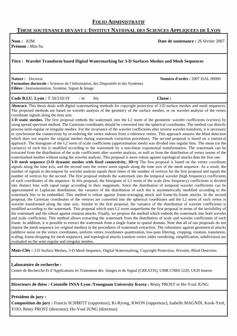
FOLIO ADMINISTRATIF
THESE SOUTENANCE DEVANT L’INSTITUT NATIONAL DES SCIENCES APPLIQUEES DE LYON
Nom : KIM Date de soutenance : 26 février 2007Prénom : Min-Su
Titre : Wavelet Transform based Digital Watermarking for 3-D Surfaces Meshes and Mesh Sequences
Nature : Doctorat Numéro d’ordre : 2007 ISAL 00000 Formation doctorale : Sciences de l’Information, des Dispositifs et des Systèmes Filière : Instrumentation, Système, Signal & Image
Code B.I.U. Lyon : T 50/210/19 / et bis Classe :
Abstract: This thesis deals with digital watermarking methods for copyright protection of 3-D surface meshes and mesh sequences. The proposed methods are based on wavelet analysis of the geometry of the surface meshes, or on wavelet analysis of the vertex coordinate signals along the time axis. 3-D static meshes. The first proposal embeds the watermark into the L2 norm of the geometric wavelet coefficients (vectors) by using spread spectrum method. The Cartesian coordinates should be converted into the spherical coordinates. The method can directly process semi-regular or irregular meshes. For the invariance of the wavelet coefficients after inverse wavelet transform, it is necessary to synchronize the connectivity by re-ordering the vertex indexes from a reference vertex. This approach ensures the blind detection which does not require the original meshes during watermark extraction procedures. The second proposal is based on a statistical approach. The histogram of the L2 norm of scale coefficients (approximation mesh) was divided into regular bins. The mean (or the variance) of each bin is modified according to the watermark by a non-linear exponential transformation. The watermark can be extracted from the distribution of the scale coefficients after wavelet analysis, as well as from the distribution of vertex norms of the watermarked meshes without using the wavelet analysis. This proposal is more robust against topological attacks than the first one. 3-D mesh sequence (3-D dynamic meshes with fixed connectivity, 3D+t) The first proposal is based on the vertex coordinate signals along the time axis, and the second uses the vertex norm signals along the time axis of the mesh sequence. As a result, the number of signals to decompose by wavelet analysis equals three times of the number of vertices for the first proposal and equals the number of vertices for the second. The first proposal embeds the watermark into the temporal wavelet (high frequency) coefficients of each coordinates of the sequence. In this proposal, the histogram of L2 norm of the scale (low frequency) coefficients is divided into distinct bins with equal range according to their magnitude. Since the distribution of temporal wavelet coefficients can be approximated to Laplacian distribution, the variance of the distribution of each bin is asymmetrically modified according to the watermark bits to be embedded. This method is robust against frame-averaging attack and frame-by-frame attacks. In the second proposal, the Cartesian coordinates of the vertices are converted into the spherical coordinates and the L2 norm of each vertex is wavelet transformed along the time axis. Similar to the first proposal, the variance of the distribution of wavelet coefficients is modified according to the watermark. This proposal which uses L2 norm outperforms the first proposal in terms of the invisibility of the watermark and the robust against rotation attacks. Finally, we propose the method which embeds the watermark into both wavelet and scale coefficients. This method allows extracting the watermark from the distribution of scale and wavelet coefficients of each frame. In addition, it is possible to extract the watermark from a single frame in spatial domain. Note that all of our proposals do not require the mesh sequence (or original meshes) in the procedures of watermark extraction. The robustness against geometrical attacks (additive noise on the vertex coordinates, uniform vertex coordinates quantization, low-pass filtering, cropping, rotation, translation, scaling, frame-dropping for mesh sequence), and topological attacks (random vertex index reordering, simplification, subdivision) are evaluated on the semi-regular and irregular meshes.
Mots-Clés : 3-D Surface Meshes, 3-D Mesh Sequence, Digital Watermarking, Copyright Protection, Wavelet, Blind Detection
Laboratoire de recherche : Centre de Recherche Et d’Applications en Traitement des Images et du Signal (CREATIS), UMR CNRS 5220, U630 Inserm
Directeurs de thèse : Cotutelle INSA-Lyon /Yeungnam University Korea : Rémy PROST et Ho-Youl JUNG
Président de jury : Composition du jury : Francis SCHMITT (rapporteur), Ki-Ryong, KWON (rapporteur), Isabelle MAGNIN, Kook-Yeol, YOO, Rémy PROST (directeur), Ho-Youl JUNG (directeur)