Embed Size (px)
Citation preview
Vergnieux R. et Delevoie C., éd. (2015),Actes du Colloque Virtual Retrospect 2013,Archéovision 6, Editions Ausonius, Bordeaux
Tiré-à-part des Actes du colloqueVirtual Retrospect 2013
Pessac (France) 27, 28 et 29 novembre 2013
Conditions d’utilisation :l’utilisation du contenu de ces pages est limitée à un usage
personnel et non commercial.Tout autre utilisation est soumise à une autorisation
préalable.Contact : [email protected]
H. PlissonDigital photography in use-wear studies, from 2D to 3
pp.35-47
Version en ligne
Digital photography in use-wear studies, from 2D to 3D
Hugues PlissonUniversité Bordeaux, CNRS, MCC, INRAP, PACEA, UMR 5199, France
Résumé : La technologie numérique a ouvert un éventail de possibilités qui était impensable à l’époque de la photographie argentique. Le remplacement du film par le capteur numérique a facilité la photographie tracéologique, en particulier en permettant le contrôle immédiat des résultats. Cependant, comme avec toute nouvelle technologie, elle n’a pas seulement apporté une nouvelle façon de faire les mêmes choses, mais le moyen de faire de nouvelles choses. Grâce à l’augmentation constante de la puissance de calcul des ordinateurs, impliquant logiciels et / ou des services en ligne, l’imagerie virtuelle est devenue accessible à la tracéologie en produisant des représentations qui ne sont plus une transposition optique directe mais des constructions mathématiques basée sur l’analyse de séries de photos, prises selon un même axe ou selon des axes différents. Pour autant, cela n’a pas aboli les principes optiques, lesquels demeurent critiques à fort grossissement. L’article rappelle les principes de base de la macrophotographie et de la microphotographie et présente des solutions d’imagerie 2D et 3D, facilement accessibles, modulables et qui peuvent être utilisées sur le terrain ou dans les musées.
Mots-clés : tracéologie, microphotographie, macrophotographie, imagerie numérique, 3D, photogrammétrie, compilation d’images, empilement des plans de mise au point
Abstract : Digital technology has opened a range of possibilities that was unthinkable at the time of film camera. The replacement of film by digital sensors has made traceological photography easier in particular because it allows the immediate control of the result, however, such as any new technology, this has not only introduced a new way for doing the same things but a way for doing new things. Thanks to the constant increasing of computing power, involving software and/or web-services, virtual imaging becomes accessible to use-wear studies by making
representations which are no longer a direct transposition of the optical images but a mathematical construction based on the analysis of a series of photos, taken under a single of different axes. Nevertheless, this has not changed the optical principles which remain critical at high magnification. This paper reminds the basic principles of photomacro and micrography and provides 2D and 3D imaging solutions that are easily accessible, flexible and can be used in the field or museums.
Keywords : traceology, use-wear analysis, photomicrography, photomicrography, digital imaging, 3D, photogrammetry, image stacking, focus stacking
INTRoDUCTIoN
“Archaeologists have not yet introduced into their general practice all those means of establishing and documenting evidence which contemporary techniques place at their disposal. This is particularly the case in micro-photography, stereography and micro-stereography (…)” (Semenov 1964, 26)
Since the origin the discipline visual demonstration has been fundamental. The book of Semenov (1957/1964) which opened world archaeology to use-wear study contains more than a hundred plates of illustrations combining several hundreds of drawings and photos. Today, it is common to start reading an article in use-wear studies by looking first at the photos in order to appraise the quality of the research. At a more epistemological level, we know that few of our current theories or assumptions will resist future data and synthesis,
Virtual Retrospect 2013 - Session 1 27, 28, 29 Novembre
36
as is normal in science, but our concrete observations will certainly remain meaningful to our successors if we are able to show them what we saw.In this perspective photography is the more widely used solution even if complementary drawings are helpful for underlying unclear details or for pedagogic purposes.Producing good photos is less a matter of using sophisticated instruments than a matter of knowing how to get the best from the available equipment. To date, the illustrations produced by S. A. Semenov, and even more by V. E. Shchelinskij (1977; in Plisson 1988), in Soviet Union, or by P. Vaughan (1985), on the Western side, remain unequaled. All three were using ancient (Wild M50) or very ancient (various Lomo models) microscopes and manual cameras.The replacement of film by digital sensors has made traceological photography easier particularly because it provides immediate control of the result and of the frame and focus before the shot. Nevertheless, the optical principles have not changed and their understanding remains critical at high magnification. The rapid progress in the automatic control of the cameras partly explains why these principles are today seldom put into practice. Mass production has considerably reduced the cost of photo equipment while its quality has remarkably increased. This equipment is far better and easier to use than in the time of the pioneers of traceology but, paradoxically, fewer scholars today know how to get good photographical results. Various solutions are now becoming available for making 3D modeling by image correlation, however the quality of the three-dimensional reconstruction does depend on the quality of the initial set of photographs, i.e. on the control of parameters which are critical in photomacro and micrography.This is the reason why, before starting to take profit of the third dimension in wear studies, it is worth considering practical points which contribute to the quality of photographs at low and high magnification.Since archaeologists are nomadic, I shall focus only on solutions that are easily available, flexible, and that can be used in the most remote museum or in the field. Therefore I will not discuss heavy equipment such as SEM or confocal microscopes. These equipments are not only cumbersome but also very expensive. Moreover, their use in traceological analysis is complementary to – and does not preclude – macroscopic observations or examination with an optical stereomicroscope and a metallurgical microscope.
WHICH CAMERA?
For recording images we need a camera. Three types are currently used in traceology: video, compact and single lens reflex (SLR) cameras. Whatever the technology involved – film or digital sensor – the most important criteria remains the size of the light sensitive surface. Despite the use of non-coated objectives, nobody has equaled the quality of the photomacrographs made by V. E. Shchelinskij (1977; Plisson
1988) who was working with a pre-war equipment and very large glass negative. on this criteria the SLR camera is far ahead with 15x24 or 24x36 mm sensor, comparing with the 2/3 or 1/1.8 inch (8.8x6.6 or 7.2x5.3 mm) for video and most compact cameras. Another criteria often misevaluated is the number of pixels. It is important to underline that this criteria is meaningless if you don’t take into consideration the size of the photodiodes on which depends: i) the dynamic range of the produced image (ie. property to record simultaneously details in the brightest and darkest areas); ii) the diffraction which fixes the highest achievable point-to-point resolution. The smaller the photodiode is, the lower is the contrast ratio, and the more lens resolution is needed in order to match the sensor with the objective. The size of the photodiodes also affects the amount of the electronic background noise and other negative interferences such as chromatic aberration. Consequently, among digital sensor matrixes of the same resolution, the best result is achieved by SLR cameras. The microscope manufacturers who sell specific video cameras which are considerably more expensive than SLR models claimed until recently that 2 million pixels (Mp) were sufficient for microphotography considering the optical resolution of microscope objectives. They now propose systems based on the same kind of tiny sensors but which are able, via complex shot interpolation and micro-scanning, to reach up to 12 Mp. Their imaging systems are certainly appropriate for various scientific disciplines or industrial applications, but do not meet the expectation and working conditions of the archaeologist. Archaeologists do not need to record the swimming speed of bacteria at 27 frames per second, but very subtle variations of relief and shape of static surfaces and edges at different scales. They study materials as different as flint, quartz, basalt, bone, antler, ivory, metal or ceramic, and sometimes the analysis needs to be done directly in the field (millstone, rock art, etc).When SLR cameras were very expensive the compact ones offered a more than acceptable alternative, and some of them performed amazingly well at macroscopic scale without any additional accessories (Plisson & Lompré 2008, photo 1). However, this is no longer the case. Furthermore, as a result of a lack of standardization among compact cameras, the cost of the scope adapters, when available, is often higher than the price of an entry-level SLR.
WHICH oPTICAL SySTEM?
Before recording the image of an object with any camera, it is first necessary to form this image by projecting on a plane the focused light rays coming from the object by using an optical device. The complexity of this optical device, which at the origin was nothing more than the hole of the camera obscura, depends on the expected magnification: the more distant or the smaller the object, the more significant are the optical aberrations that have to be controlled. In our case the range of scale is large, from centimeter to micron.
Digital photography in use-wear studies, from 2D to 3D H. Plisson
37
Direct observation can accommodate with a mediocre optical system since it relies on the most powerful image processor, the brain. The brain can create an ideal synthetic mental image by instantaneously compiling multiple views, filtering non relevant features and comparing them with memorized models. obviously, this is not the case with digital sensors. Photography emphasizes even the smallest aberration and does not afford any optical compromise. Compared with direct observation, photomacro or micrography is often deceiving. However, the final result can be greatly improved if quite simple solutions are adopted and some basic principles respected. As for the direct observation, we can distinguish 3 steps of magnification in use-wear photography: what is visible at naked eye, what requires the help of an optical device for seeing the relevant features, and what is invisible without a microscope. Each step involves different equipment.
Close-up photography
For subjects up to a centimeter, close-up photography can be done directly with a photo macro objective of 50 or 100 mm. Each SLR camera manufacturer supplies this type of objective. The most recent models give the best since their full aperture. However, their optical design, based on an internal focusing (only the internal lenses move), reduces the focal length when increasing the magnification, and this can preclude some applications. Most of these macro objectives directly reach a magnification of 1x at the sensor plane, life size, written 1:1. With a DX format sensor (15x25 mm) the frame is the same as seen in direct observation with, for example, a Leica MZ6 or Nikon SMZ2B stereoscope at 8X with 10x/21 oculars.
Photomacrography
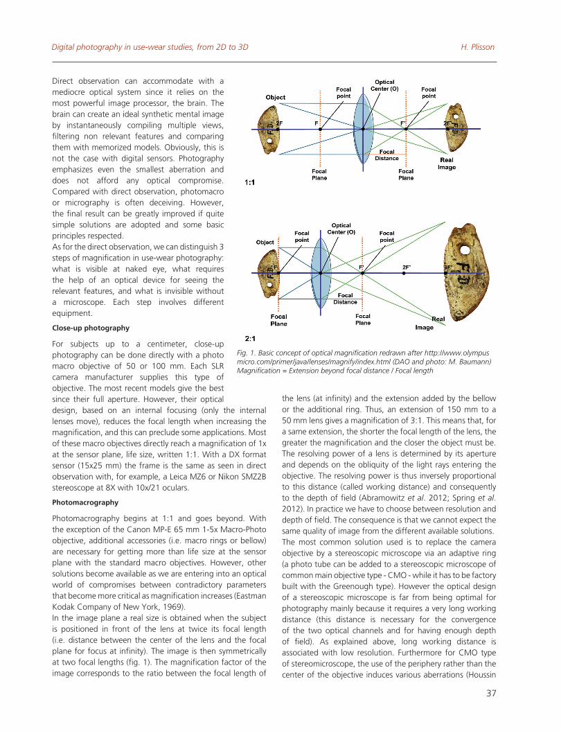
Photomacrography begins at 1:1 and goes beyond. With the exception of the Canon MP-E 65 mm 1-5x Macro-Photo objective, additional accessories (i.e. macro rings or bellow) are necessary for getting more than life size at the sensor plane with the standard macro objectives. However, other solutions become available as we are entering into an optical world of compromises between contradictory parameters that become more critical as magnification increases (Eastman Kodak Company of New york, 1969). In the image plane a real size is obtained when the subject is positioned in front of the lens at twice its focal length (i.e. distance between the center of the lens and the focal plane for focus at infinity). The image is then symmetrically at two focal lengths (fig. 1). The magnification factor of the image corresponds to the ratio between the focal length of
the lens (at infinity) and the extension added by the bellow or the additional ring. Thus, an extension of 150 mm to a 50 mm lens gives a magnification of 3:1. This means that, for a same extension, the shorter the focal length of the lens, the greater the magnification and the closer the object must be. The resolving power of a lens is determined by its aperture and depends on the obliquity of the light rays entering the objective. The resolving power is thus inversely proportional to this distance (called working distance) and consequently to the depth of field (Abramowitz et al. 2012; Spring et al. 2012). In practice we have to choose between resolution and depth of field. The consequence is that we cannot expect the same quality of image from the different available solutions.The most common solution used is to replace the camera objective by a stereoscopic microscope via an adaptive ring (a photo tube can be added to a stereoscopic microscope of common main objective type - CMo - while it has to be factory built with the Greenough type). However the optical design of a stereoscopic microscope is far from being optimal for photography mainly because it requires a very long working distance (this distance is necessary for the convergence of the two optical channels and for having enough depth of field). As explained above, long working distance is associated with low resolution. Furthermore for CMo type of stereomicroscope, the use of the periphery rather than the center of the objective induces various aberrations (Houssin
Fig. 1. Basic concept of optical magnification redrawn after http://www.olympus micro.com/primer/java/lenses/magnify/index.html (DAO and photo: M. Baumann) Magnification = Extension beyond focal distance / Focal length
Virtual Retrospect 2013 - Session 1 27, 28, 29 Novembre
38
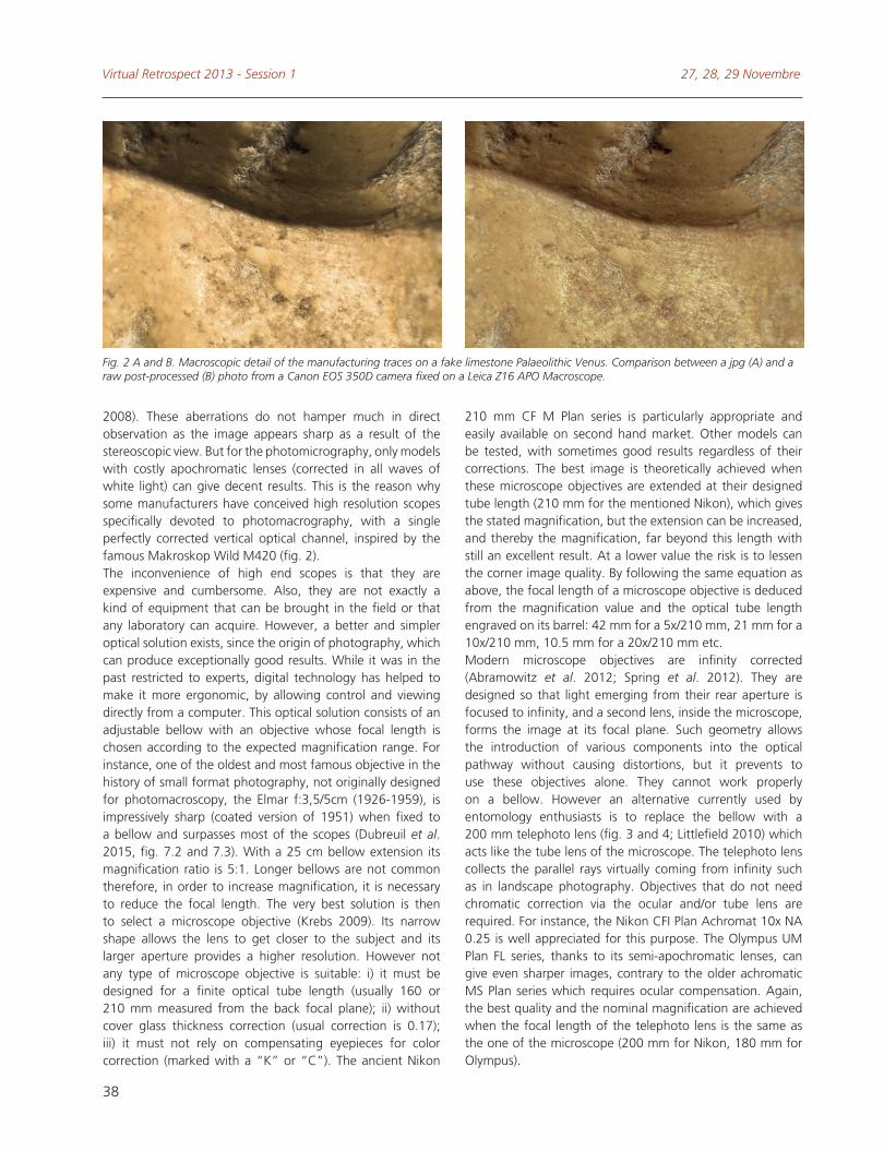
2008). These aberrations do not hamper much in direct observation as the image appears sharp as a result of the stereoscopic view. But for the photomicrography, only models with costly apochromatic lenses (corrected in all waves of white light) can give decent results. This is the reason why some manufacturers have conceived high resolution scopes specifically devoted to photomacrography, with a single perfectly corrected vertical optical channel, inspired by the famous Makroskop Wild M420 (fig. 2). The inconvenience of high end scopes is that they are expensive and cumbersome. Also, they are not exactly a kind of equipment that can be brought in the field or that any laboratory can acquire. However, a better and simpler optical solution exists, since the origin of photography, which can produce exceptionally good results. While it was in the past restricted to experts, digital technology has helped to make it more ergonomic, by allowing control and viewing directly from a computer. This optical solution consists of an adjustable bellow with an objective whose focal length is chosen according to the expected magnification range. For instance, one of the oldest and most famous objective in the history of small format photography, not originally designed for photomacroscopy, the Elmar f:3,5/5cm (1926-1959), is impressively sharp (coated version of 1951) when fixed to a bellow and surpasses most of the scopes (Dubreuil et al. 2015, fig. 7.2 and 7.3). With a 25 cm bellow extension its magnification ratio is 5:1. Longer bellows are not common therefore, in order to increase magnification, it is necessary to reduce the focal length. The very best solution is then to select a microscope objective (Krebs 2009). Its narrow shape allows the lens to get closer to the subject and its larger aperture provides a higher resolution. However not any type of microscope objective is suitable: i) it must be designed for a finite optical tube length (usually 160 or 210 mm measured from the back focal plane); ii) without cover glass thickness correction (usual correction is 0.17); iii) it must not rely on compensating eyepieces for color correction (marked with a “K” or “C”). The ancient Nikon
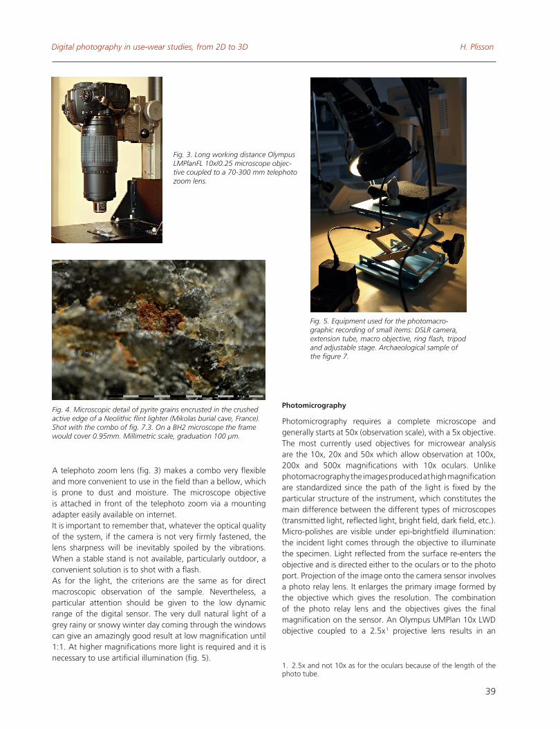
210 mm CF M Plan series is particularly appropriate and easily available on second hand market. other models can be tested, with sometimes good results regardless of their corrections. The best image is theoretically achieved when these microscope objectives are extended at their designed tube length (210 mm for the mentioned Nikon), which gives the stated magnification, but the extension can be increased, and thereby the magnification, far beyond this length with still an excellent result. At a lower value the risk is to lessen the corner image quality. By following the same equation as above, the focal length of a microscope objective is deduced from the magnification value and the optical tube length engraved on its barrel: 42 mm for a 5x/210 mm, 21 mm for a 10x/210 mm, 10.5 mm for a 20x/210 mm etc.Modern microscope objectives are infinity corrected (Abramowitz et al. 2012; Spring et al. 2012). They are designed so that light emerging from their rear aperture is focused to infinity, and a second lens, inside the microscope, forms the image at its focal plane. Such geometry allows the introduction of various components into the optical pathway without causing distortions, but it prevents to use these objectives alone. They cannot work properly on a bellow. However an alternative currently used by entomology enthusiasts is to replace the bellow with a 200 mm telephoto lens (fig. 3 and 4; Littlefield 2010) which acts like the tube lens of the microscope. The telephoto lens collects the parallel rays virtually coming from infinity such as in landscape photography. objectives that do not need chromatic correction via the ocular and/or tube lens are required. For instance, the Nikon CFI Plan Achromat 10x NA 0.25 is well appreciated for this purpose. The olympus UM Plan FL series, thanks to its semi-apochromatic lenses, can give even sharper images, contrary to the older achromatic MS Plan series which requires ocular compensation. Again, the best quality and the nominal magnification are achieved when the focal length of the telephoto lens is the same as the one of the microscope (200 mm for Nikon, 180 mm for olympus).
Fig. 2 A and B. Macroscopic detail of the manufacturing traces on a fake limestone Palaeolithic Venus. Comparison between a jpg (A) and a raw post-processed (B) photo from a Canon EOS 350D camera fixed on a Leica Z16 APO Macroscope.
Digital photography in use-wear studies, from 2D to 3D H. Plisson
39
A telephoto zoom lens (fig. 3) makes a combo very flexible and more convenient to use in the field than a bellow, which is prone to dust and moisture. The microscope objective is attached in front of the telephoto zoom via a mounting adapter easily available on internet.It is important to remember that, whatever the optical quality of the system, if the camera is not very firmly fastened, the lens sharpness will be inevitably spoiled by the vibrations. When a stable stand is not available, particularly outdoor, a convenient solution is to shot with a flash. As for the light, the criterions are the same as for direct macroscopic observation of the sample. Nevertheless, a particular attention should be given to the low dynamic range of the digital sensor. The very dull natural light of a grey rainy or snowy winter day coming through the windows can give an amazingly good result at low magnification until 1:1. At higher magnifications more light is required and it is necessary to use artificial illumination (fig. 5).
Photomicrography
Photomicrography requires a complete microscope and generally starts at 50x (observation scale), with a 5x objective. The most currently used objectives for microwear analysis are the 10x, 20x and 50x which allow observation at 100x, 200x and 500x magnifications with 10x oculars. Unlike photomacrography the images produced at high magnification are standardized since the path of the light is fixed by the particular structure of the instrument, which constitutes the main difference between the different types of microscopes (transmitted light, reflected light, bright field, dark field, etc.). Micro-polishes are visible under epi-brightfield illumination: the incident light comes through the objective to illuminate the specimen. Light reflected from the surface re-enters the objective and is directed either to the oculars or to the photo port. Projection of the image onto the camera sensor involves a photo relay lens. It enlarges the primary image formed by the objective which gives the resolution. The combination of the photo relay lens and the objectives gives the final magnification on the sensor. An olympus UMPlan 10x LWD objective coupled to a 2.5x 1 projective lens results in an
1. 2.5x and not 10x as for the oculars because of the length of the photo tube.
Fig. 3. Long working distance Olympus LMPlanFL 10x/0.25 microscope objec-tive coupled to a 70-300 mm telephoto zoom lens.
Fig. 5. Equipment used for the photomacro-graphic recording of small items: DSLR camera, extension tube, macro objective, ring flash, tripod and adjustable stage. Archaeological sample of the figure 7.
Fig. 4. Microscopic detail of pyrite grains encrusted in the crushed active edge of a Neolithic flint lighter (Mikolas burial cave, France). Shot with the combo of fig. 7.3. On a BH2 microscope the frame would cover 0.95mm. Millimetric scale, graduation 100 µm.
Virtual Retrospect 2013 - Session 1 27, 28, 29 Novembre
40
image of 25:1 magnification ratio 2. It is 2.5x more than when attached to a telephoto zoom lens at its focal length (180 mm – but 16.7:1 at 300 mm). However, since the quality of the image depends on the characteristics of the objective, the change of enlargement does not make a significant difference (Plisson 1989, fig. 2 and 4). In fact, the diversity in the type of illumination is more fundamental. It has not only to do with the path of the beam (through the lens or external) but also a variety of principles inherent to microscopy (Abramowitz et al. 2012; Spring et al. 2012). Among them, the differential interference contrast (DIC), which is based on interferometry, is particularly useful for the examination of translucent or transparent and clear surfaces and to see otherwise invisibles features. A translating beamsplitting prism (called Nomarski prism) is inserted before the objective with two linear
2. What can be precisely measured by shooting a micrometric scale and by dividing the side of the frame, whose length is known (= sensor size), by the length of this scale.
A
B
C
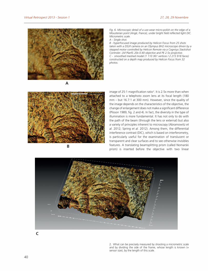
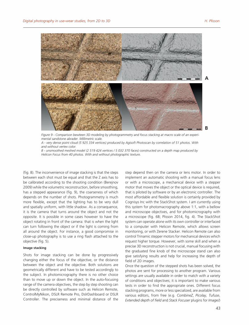
Fig. 6. Microscopic detail of a use-wear micro-polish on the edge of a Mousterian point (Angé, France), under bright field reflected light DIC. Micrometric scale.A - Single shot. B - hyperfocused image produced by Helicon Focus from 25 shots taken with a DSLR camera on an Olympus BH2 microscope driven by a stepped motor controlled by Helicon Remote via a Cognisys Stackshot Controler. LM PlanFL 20x 0.40 objective and PE 2.5x projective.C - smoothed meshed model (1 110 361 vertices / 2 215 918 faces) constructed on a depth map produced by Helicon Focus from 32 photos.
Digital photography in use-wear studies, from 2D to 3D H. Plisson
41
polarizers. one polarizer is inserted in the path of incoming light and the second after the prism in the path of light reflected from the specimen surface. The DIC produces a bias retardation which enhances the perception of the micro topographical variations of the surface and of the overall contrast. The effect is obvious in direct observation. DIC also reduces chromatic aberration, a phenomenon to which digital sensors 3 are particularly sensitive. In fact, even when the sample texture or micro-relief does not require this kind of vertical resolution enhancement, the DIC still improves the quality of the photography (fig. 6; Plisson & Lompré 2008, photos 6-7). However, modern Nomarski prisms can be too strong for coarse grain stones, causing a kind of double image, and in such case it is advisable to use prisms of more ancient design... At the opposite, recent models work fine with quartz or obsidian tools (Plisson 2008).
DIGITAL TooLS
Up to now, except the cameras, there is nothing unique to digital technology. We could use them in the same way as film cameras, as we did at the beginning of digital photography. However, generally a new technology does not only offer a new way of doing the same things but also introduces new practices.There are a number of software tools which are relevant to traceological imaging.There are three fundamental types of software: remote shooting, image processing and image analyzer. We will consider the first two types that are directly related to the quality of the images produced.Remote shooting software allows the control of the SLR camera from a computer, a tablet or even a smartphone, and a direct monitoring of the frame and focus with the Live Preview function. All or most of the camera adjustments can be done on the computer or pad screen, and the automation of the shots with specific parameters is possible. Such programs are provided by the camera manufacturers or by third party editors. The programs with the most advanced options are designed only for the cameras issued by the two main Japanese companies. Among the remote programs, Helicon Remote from Helicon Soft Company is certainly the most impressive. It comes as a complementary module of Helicon Focus for automating focus and exposure bracketing and is available for Windows, Mac and Android 3.1+ oS. It progressively changes, step by step, the focus of the objective mounted on the SLR camera, taking a shot at each step, what results in a vertical photographical scanning of the sample. For Nikon and PC users a worthwhile alternative for remote bracketing and monitoring is provided by ControlMyNikon,
3. With film cameras photomicrography of micro-wear was generally done in black and white, through a green filter for using the achromatic lenses in the wave’s band for which they are corrected, what would blind half of the pixels of a current digital sensor.
while DslrDashboard and DSLR Controller (Canon only) are two valuable solutions with Android tablets and smartphones.Image processing software is of two types: for converting its raw file in standard format (jpg, tif, etc.), for making a new image from several. Each SLR camera has its own raw format, which is the digital equivalent of the film negative, that encode the image in 12, 14 or 16 bits color depth (Verhoeven 2010). Any adjustment of the image quality made before shooting (contrast, sharpness, color balance, saturation, etc.) can be afterward corrected or cancelled when operating in raw format, which is not the case in jpg or tif. Moreover, a 12, 14 or 16 bits encoding gives a larger contrast range than the 8 bits of the jpg format since more information is recorded (fig. 2). Furthermore, even at the lowest compression ratio, each time a jpg file is saved the image is altered. For a scientific purpose it is therefore more advisable to shoot in raw format as you can get many different renderings. Depending on the camera company, the raw converter program is either included in the camera package or has to be purchased separately. In the second case, it is worth comparing the price and performance with third party software. Whatever the program used, converting a raw image independently from the camera allows taking advantage of the regular evolution of software and processors and provides access to all range of solutions to improve the final result, such as using a better converter. obviously, that is not the case when the conversion is done by the internal graphic processor of the camera.With virtual imaging we are entering into the digital dimension of photography. Virtual imaging allows creating a representation that is no longer the direct transposition of an optical image but a mathematical construction based on the analysis of a series of photos. Three applications are particularly useful for use wear analysis. They are based on two different principles: the treatment of several photos taken under i) a single axis (focus stacking) or ii) different axes (photogrammetry).Image stacking (also called z-stacking, depth of field stacking, multifocus or focal plane merging) enhances the depth of field of two dimensional views (fig. 6 A-B). This is particularly interesting in photomicrography (e.g. Thiéry & Green 2011), especially when working with high resolution lenses. Image stacking can also provide three-dimensional reconstructions (fig. 6 C), the resolution of which depends on the number and regularity of shots. Photogrammetry is devoted only to 3D and has the capacity to reconstruct an entire volume (Pierrot Deseilligny & Clery 2011). It works by assigning absolute coordinates to each point. In practice, both solutions are complementary because they have opposite requirements: whereas photogrammetry needs a wide depth of field, image stacking requires a low depth of field. Consequently, the only modus operandi at high magnification is image stacking (fig. 6) while photogrammetry is more appropriate at low magnification up to 1.5:1 (fig. 7) and for whole objects
Virtual Retrospect 2013 - Session 1 27, 28, 29 Novembre
42
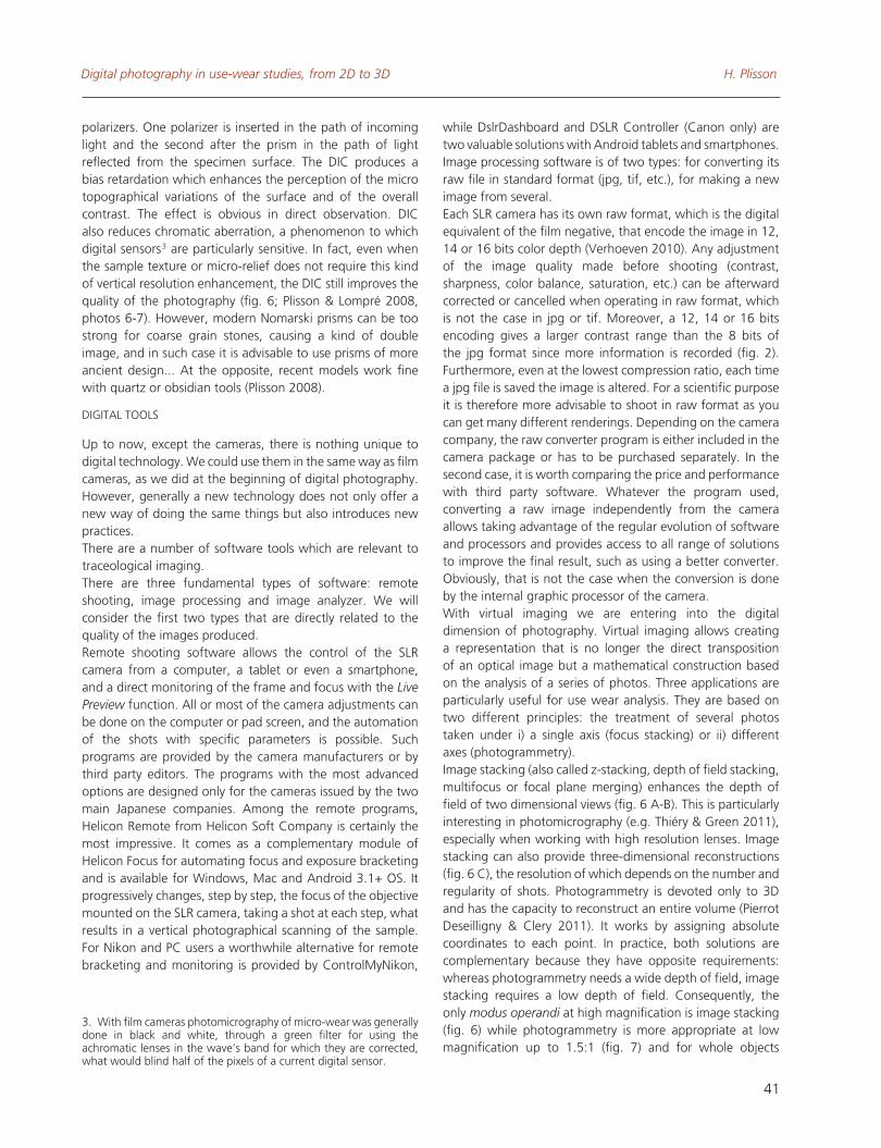
Fig. 7. Photogrammetric modeling of the blunted tip of a Gravettian pick from Olga Grande 4, Coa Valley, Portugal. Millimetric scale.A and B - Above: 1 of 87 photos. Below: very dense point cloud (6 024 588 vertices) produced by Agisoft Photoscan. C - light point cloud (102 158 vertices) produced by Autodesk 123D Catch. Best resolution available on June 4th 2014.
CA
B
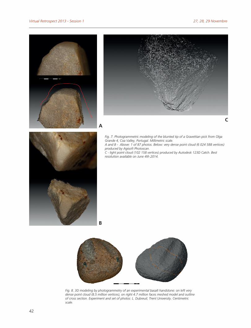
Fig. 8. 3D modeling by photogrammetry of an experimental basalt handstone: on left very dense point cloud (8.5 million vertices), on right 4.7 million faces meshed model and outline of cross section. Experiment and set of photos: L. Dubreuil, Trent University. Centimetric scale.
Digital photography in use-wear studies, from 2D to 3D H. Plisson
43
(fig. 8). The inconvenience of image stacking is that the steps between each shot must be equal and that the Z axis has to be calibrated according to the shooting condition (Berejnov 2009) while the volumetric reconstruction, before smoothing, has a stepped appearance (fig. 9), the coarseness of which depends on the number of shots. Photogrammetry is much more flexible, except that the lighting has to be very dull and spatially uniform, with little shadow. As a consequence, it is the camera that turns around the object and not the opposite. It is possible in some cases however to have the object rotating in front of the camera: that is when the light can turn following the object or if the light is coming from all around the object. For instance, a good compromise in close-up photography is to use a ring flash attached to the objective (fig. 5).
Image stacking
Shots for image stacking can be done by progressively changing either the focus of the objective, or the distance between the object and the objective. Both solutions are geometrically different and have to be tested accordingly to the subject. In photomicrography there is no other choice than to move up or down the object. In the auto-focusing range of the camera objectives, the step by step shooting can be directly controlled by software such as Helicon Remote, ControlMyNikon, DSLR Remote Pro, DslrDashboard or DSLR Controller. The preciseness and minimal distance of the
step depend then on the camera or lens motor. In order to implement an automatic shooting with a manual focus lens or with a microscope, a mechanical device with a stepper motor that moves the object or the optical device is required, that is piloted by software or by an electronic controller. The most affordable and flexible solution is certainly provided by Cognisys Inc with the StackShot system. I am currently using this system for photomacrography above 1:1, with a bellow and microscope objectives, and for photomicrography with a microscope (fig. 6B; Plisson 2014, fig. 4). The StackShot system can operate alone with its own controller or interfaced to a computer with Helicon Remote, which allows screen monitoring, or with Zerene Stacker. Helicon Remote can also control Trinamic stepper motors for mechanical devices which request higher torque. However, with some skill and when a precise 3D reconstruction is not crucial, manual focusing with the graduated fine knob of the microscope stand can also give satisfying results and help for increasing the depth of field of 2D images.once the question of the stepped shots has been solved, the photos are sent for processing to another program. Various settings are usually available in order to match with a variety of conditions and objectives; it is important to make various tests in order to find the appropriate ones. Different focus stacking programs, more or less specialized, are available from various editors, from free (e.g. CombineZ, Picolay, Tufuse, Extended depth of field and Stack Focuser plugins for ImageJ)
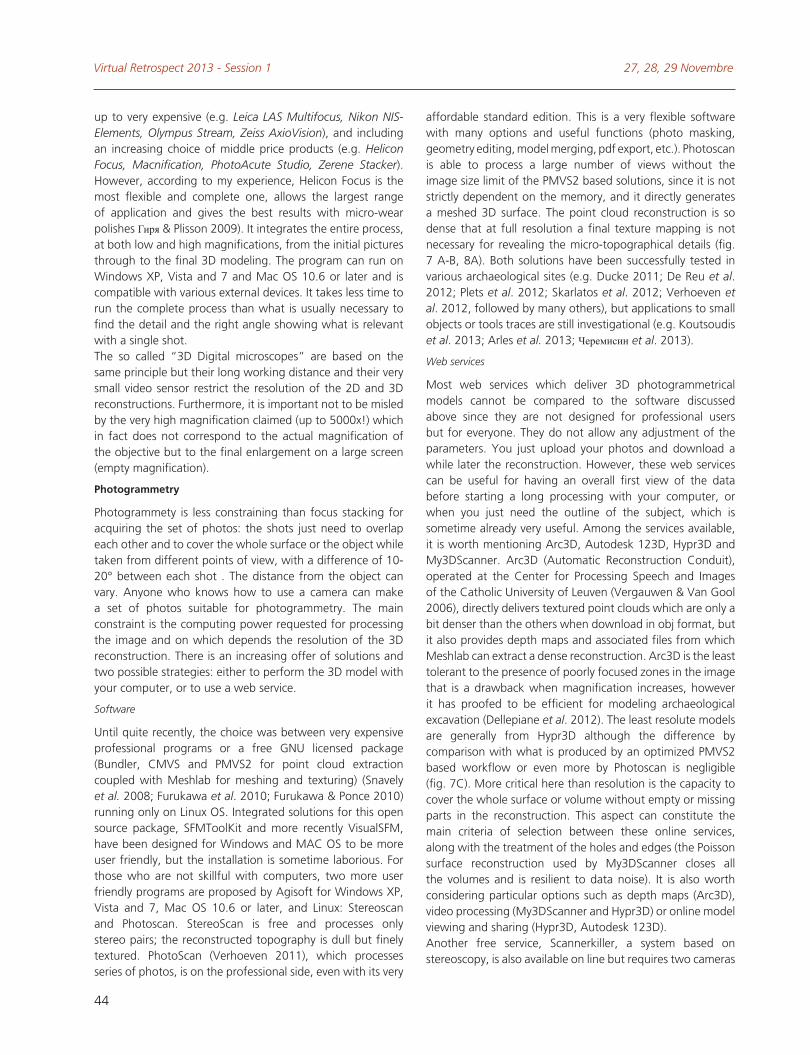
Figure 9 - Comparison bewteen 3D modeling by photogrammetry and focus stacking at macro scale of an experi-mental sandstone abrader. Millimetric scale.A - very dense point cloud (5 925 334 vertices) produced by Agisoft Photoscan by correlation of 51 photos. With and without vertex color.B - unsmoothed meshed model (2 519 424 vertices / 5 032 370 faces) constructed on a depth map produced by Helicon Focus from 40 photos. With and without photographic texture.
A
B
Virtual Retrospect 2013 - Session 1 27, 28, 29 Novembre
44
up to very expensive (e.g. Leica LAS Multifocus, Nikon NIS-Elements, Olympus Stream, Zeiss AxioVision), and including an increasing choice of middle price products (e.g. Helicon Focus, Macnification, PhotoAcute Studio, Zerene Stacker). However, according to my experience, Helicon Focus is the most flexible and complete one, allows the largest range of application and gives the best results with micro-wear polishes Гиря & Plisson 2009). It integrates the entire process, at both low and high magnifications, from the initial pictures through to the final 3D modeling. The program can run on Windows XP, Vista and 7 and Mac oS 10.6 or later and is compatible with various external devices. It takes less time to run the complete process than what is usually necessary to find the detail and the right angle showing what is relevant with a single shot. The so called “3D Digital microscopes” are based on the same principle but their long working distance and their very small video sensor restrict the resolution of the 2D and 3D reconstructions. Furthermore, it is important not to be misled by the very high magnification claimed (up to 5000x!) which in fact does not correspond to the actual magnification of the objective but to the final enlargement on a large screen (empty magnification).
Photogrammetry
Photogrammety is less constraining than focus stacking for acquiring the set of photos: the shots just need to overlap each other and to cover the whole surface or the object while taken from different points of view, with a difference of 10-20° between each shot . The distance from the object can vary. Anyone who knows how to use a camera can make a set of photos suitable for photogrammetry. The main constraint is the computing power requested for processing the image and on which depends the resolution of the 3D reconstruction. There is an increasing offer of solutions and two possible strategies: either to perform the 3D model with your computer, or to use a web service.
Software
Until quite recently, the choice was between very expensive professional programs or a free GNU licensed package (Bundler, CMVS and PMVS2 for point cloud extraction coupled with Meshlab for meshing and texturing) (Snavely et al. 2008; Furukawa et al. 2010; Furukawa & Ponce 2010) running only on Linux oS. Integrated solutions for this open source package, SFMToolKit and more recently VisualSFM, have been designed for Windows and MAC oS to be more user friendly, but the installation is sometime laborious. For those who are not skillful with computers, two more user friendly programs are proposed by Agisoft for Windows XP, Vista and 7, Mac oS 10.6 or later, and Linux: Stereoscan and Photoscan. StereoScan is free and processes only stereo pairs; the reconstructed topography is dull but finely textured. PhotoScan (Verhoeven 2011), which processes series of photos, is on the professional side, even with its very
affordable standard edition. This is a very flexible software with many options and useful functions (photo masking, geometry editing, model merging, pdf export, etc.). Photoscan is able to process a large number of views without the image size limit of the PMVS2 based solutions, since it is not strictly dependent on the memory, and it directly generates a meshed 3D surface. The point cloud reconstruction is so dense that at full resolution a final texture mapping is not necessary for revealing the micro-topographical details (fig. 7 A-B, 8A). Both solutions have been successfully tested in various archaeological sites (e.g. Ducke 2011; De Reu et al. 2012; Plets et al. 2012; Skarlatos et al. 2012; Verhoeven et al. 2012, followed by many others), but applications to small objects or tools traces are still investigational (e.g. Koutsoudis et al. 2013; Arles et al. 2013; Черемисин et al. 2013).
Web services
Most web services which deliver 3D photogrammetrical models cannot be compared to the software discussed above since they are not designed for professional users but for everyone. They do not allow any adjustment of the parameters. you just upload your photos and download a while later the reconstruction. However, these web services can be useful for having an overall first view of the data before starting a long processing with your computer, or when you just need the outline of the subject, which is sometime already very useful. Among the services available, it is worth mentioning Arc3D, Autodesk 123D, Hypr3D and My3DScanner. Arc3D (Automatic Reconstruction Conduit), operated at the Center for Processing Speech and Images of the Catholic University of Leuven (Vergauwen & Van Gool 2006), directly delivers textured point clouds which are only a bit denser than the others when download in obj format, but it also provides depth maps and associated files from which Meshlab can extract a dense reconstruction. Arc3D is the least tolerant to the presence of poorly focused zones in the image that is a drawback when magnification increases, however it has proofed to be efficient for modeling archaeological excavation (Dellepiane et al. 2012). The least resolute models are generally from Hypr3D although the difference by comparison with what is produced by an optimized PMVS2 based workflow or even more by Photoscan is negligible (fig. 7C). More critical here than resolution is the capacity to cover the whole surface or volume without empty or missing parts in the reconstruction. This aspect can constitute the main criteria of selection between these online services, along with the treatment of the holes and edges (the Poisson surface reconstruction used by My3DScanner closes all the volumes and is resilient to data noise). It is also worth considering particular options such as depth maps (Arc3D), video processing (My3DScanner and Hypr3D) or online model viewing and sharing (Hypr3D, Autodesk 123D).Another free service, Scannerkiller, a system based on stereoscopy, is also available on line but requires two cameras
Digital photography in use-wear studies, from 2D to 3D H. Plisson
45
and a precise calibration, which makes the system less flexible than photogrammetry. In any case, before using non-institutional web services for scientific purposes, moreover with unpublished documents, one must pay attention to the Terms of service and Copyright policy.
CoNCLUSIoN
Whatever the solution chosen, nothing is irreversible as the acquisition of the photos and the processing are independent steps. From the same set of photos it will be possible to extract more and more information as the software progresses, which is not the case of scanner 4 technology. This means that a good knowledge of optical and photographical principles is still required not only for taking the best from actual digital imaging but also for having good archives ready for future. So far, 3D imaging in the field of use-wear studies, contrarily to other scientific branches, has not yet reached the step of concrete applications and could be perceived as mainly cosmetic. However this is because it was until recently an inaccessible technology for most archaeologists, and also because of the diversity of traceological scales to cover from centimeter to micron which involves different technics. Thanks to the constant increase of computing power, a new approach is becoming available which will soon find a large range of application: as always with a new technology, for doing differently what we used to do and also for achieving what was until recently impossible or very difficult to realize. Image stacking is already indispensable for pulling out of the fog the peculiar little features observed with the microscope. More fundamentally, as already pointed out by S. A. Semenov (1957, 41 / 1964, 29) and explored with V. E. Shchelinsky at microscopic scale by interferometry (1971), the third dimension can also help characterizing objectively use wear attributes (e.g. Bello et al. 2011), especially the attributes that were neglected in the absence of appropriate recording technique, such as the rounding of edges or the deformation of working surfaces (fig. 7, 8; Adams et al. 2009).The advantage is also evident for sharing observations between specialists, enriching databases, testing hypothesis through virtual reconstitution, and diffusing our work to a larger non-scientific audience. Nevertheless everything starts with the camera .
4. 3D modeling with a digital scanner requires an additional photographical recording for getting a photo textured rendering, and the density of the point cloud does not depend on an external software but on the scanner itself. Moreover there is so far no scanner available for macro and microscopic scales.
ACKNoWLEDGMENT
I am particularly grateful to Eric Pubert (Pacea) for having supplied me a computer appropriate for 3D processing, despite bureaucratic constraints, to Pascal Mora (Archeotransfert) and Bruno Dutailly (Archéovision) for having initiated me into photogrammetry, to Thierry Aubry (Parque Arqueológico do Vale do Côa) for having welcomed me in the museum of Vale do Côa and giving access to the archaeological sites and collections, to Jean-Michel Geneste (CNP) and Serge Maury for lending me the two experimental sandstone abraders of fig. 5, 6, 11-13, to Malvina Baumann (University Paris 1) for fig. 1, to Laure Dubreuil (Trent University) for the set of photos and experimental handstone used for the fig. 8, and with Dan Savage (Trent University) for having improved the English. The part of this work devoted to 3D was supported by the French National Research Agency (ANR-10-LABX-52).
Virtual Retrospect 2013 - Session 1 27, 28, 29 Novembre
46
Printed references
Abramowitz, M., K. R. Spring, B. o. Flynn, J. C. Long, M. Parry-Hill, K. I. Tchourioukanov and M. W. Davidson (2012): Basic Concepts in optical Microscopy. http://www.olympusmicro.com/primer/anatomy/anatomy.html
Adams, J. L., S. Delgado, L. Dubreuil, C. Hamon, H. Plisson and R. Risch (2009): “Functional analysis of macro-lithic artefacts: a focus on working surfaces”, in: Sternke, F., L. Eigeland, L. J. Costa, eds., Non-flint Raw Material Use in Prehistory: Old Prejudices and New Direction. Proceedings of the XV World Congress U.I.S.P.P. (Lisbon, 4-9 september 2006), Archaeopress, oxford.
Arles, A., P. Clerc, G. Sarah, F. Téreygeol, G. Bonnamour, J. Heckes and A. Klein (2013): “3D reconstruction and modeling of subterranean landscapes in collaborative mining archaeology projects: techniques, applications and experiences”, XXIV International CIPA Symposium, 2-6 September 2013, Strasbourg, France. International Archives of the Photogrammetry, Remote Sensing and Spatial Information Sciences, Volume XL-5/W2.pp. 61-66. http://www.int-arch-photogramm-remote-sens-spatial-inf-sci.net/XL-5-W2/61/2013/isprsarchives-XL-5-W2-61-2013.html.
Bello, S. M., E. Verveniotou, L. Cornish and S. A. Parfitt (2011): “3-dimensional microscope analysis of bone and tooth surface modifications: comparisons of fossil specimens and replicas”, Scanning, 33, 316-324.
Berejnov, V. V. (2009) : Rapid and Inexpensive Reconstruction of 3D Structures for Micro-objects Using Common optical Microscopy, arXiv.org, Cornell University Library, p. 8. http://arxiv.org/abs/0904.2024
De Reu, J., G. Plets, G. Verhoeven, P. De Smedt, M. Bats, B. Cherretté, W. De Maeyer, J. Deconynck, D. Herremans, P. Laloo, M. Van Meirvenne and W. De Clercq (2012): “Towards a three-dimensional cost-effective registration of the archaeological heritage”, Journal of Archaeological Science, 40 (2), 1108-1121.
Dellepiane, M., N. Dell’Unto, M. Callieri, S. Lindgren and R. Scopigno (2012): “Archeological excavation monitoring using dense stereo matching techniques”, Journal of Cultural Heritage, 14 (3), 201-210s.
Ducke, B., D. Score and J. Reeves (2011): “Multiview 3D reconstruction of the archaeological site at Weymouth from image series”, Computers & Graphics, 35, 375-382.
Dubreuil, L., D. Savage, S. Delgado-Raack, H. Plisson, B. Stephenson and I. de la Torre (2015): “Current Analytical Frameworks for Studies of Use-Wear on Ground Stone Tools”, in : Marreiros J.M., Gibaja Bao J.F. et Bicho N. eds., Use-Wear and Residue Analysis in Archaeology. Manuals in Archaeological Method, Theory and Technique, Springer, New york, Dordrecht, Heidelberg, London, 105-158.
Eastman Kodak Company of New york, (1969): Close-up photography and photomacrography, Eastman kodak co.
Furukawa, y., B. Curless, S. M. Seitz and R. Szeliski (2010): Towards Internet-scale Multi-view Stereo, IEEE Conference on Computer Vision and Pattern Recognition, 1434-1441.
Furukawa, y. and J. Ponce (2010): “Accurate, Dense, and Robust Multiview Stereopsis”, IEEE Transactions on Pattern Analysis and Machine Intelligence, 32, 1362-1376.
Houssin, P. (2008): “Photographier les microminéraux avec un stereomicroscope”, Cahier des Micromonteurs de l’AFM, 99, 17-20. http://legeophile.free.fr/download/article%201%20Photo%20MM%20stereomicro%20PHoussin%20v2%20071108.pdf
Koutsoudis, A., B. Vidmar and F. Arnaoutoglou (2013): Performance evaluation of a multi-image 3D reconstruction software on
a low-feature artefact, Journal of Archaeological Science 40, 4450-4456.
Krebs, C. (2009): Microscope objectives on Camera Bellows. http://www.krebsmicro.com/obj_bellows/index.html
Littlefield R. (2010): Infinity objective on low-end zoom telephoto works fine. http://www.photomacrography.net/forum/viewtopic.php?t=9664.
Pierrot Deseilligny, M. and I. Clery (2011): “Évolutions récentes en photogrammétrie et modélisation 3D par photo des milieux naturels”, in: Jaillet, S., E. Ployon, T. Villemin, eds., Images et Modèles 3D en Milieux naturels, Edytem, Le Bourget-du-Lac, 51-66.
Plets, G., W. Gheyle, G. Verhoeven, J. De Reu, J. Bourgeois, J. Verhegge and B. Stichelbaut (2012): Three-dimensional recording of archaeological remains in the Altai Mountains Antiquity, 86, 884-897.
Plisson, H. (1988): “Technologie et tracéologie des outils lithiques moustériens en Union Soviétique : les travaux de V.E. Shchelinskij”, in: otte, M., ed., L’Homme de Neandertal, ERAUL, Liège, 121-168.
Plisson, H. (1989): “Quelques considérations sur l’équipement optique adapté à la micro-tracéologie”, Helinium, XXIX, 3-12.
— (2008): “Fonction(s) d’un racloir en cristal de roche”, in: Slimak, L., ed., Artisanats et territoires des chasseurs moustériens de Champ Grand, Paleoc, Aix en Provence, 341-321.
— (2009): “Analyse tracéologique de 4 pics d’olga Grande : des outils pour les gravures de plein air ?”, in: Aubry, T., ed., 200 séculos da história do Vale do Côa: incursões na vida quotidiana do caçadores-artistas do Paleolítico, Instituto Português de Arqueologia, Lisboa, 436-442.
Plisson, H. and A. Lompré (2008): “Technician or researcher ? A visual answer”, in: Longo, L., N. Skakun, eds., “Prehistoric Technology” 40 years later: Functional studies and the Russian legacy, BAR, oxford, 503-508.
Semenov, S. A. (1964): Prehistoric technology ; an experimental study of the oldest tools and artefacts from traces of manufacture and wear, Cory, Adams & Mackay, London.
Skarlatos, D., S. Demestiha and S. Kiparissi (2012): “An ‘open’ Method for 3D Modelling and Mapping in Underwater Archaeological Sites”, International Journal of Heritage in the Digital Era, 1, 2-23.
Snavely, N., S. Seitz and R. Szeliski (2008): “Modeling the World from Internet Photo Collections”, International Journal of Computer Vision, 80, 189-210.
Spring, K. R., H. Komatsu, M. L. Scott, S. A. Schwartz, T. J. Fellers, K. E. Carr, M. Parry-Hill and M. W. Davidson (2012): Basic Concepts and Formulas in Microscopy http://www.microscopyu.com/articles/formulas/
Thiéry, V. and D. I. Green (2012): “The multifocus imaging technique in petrology”, Computers & Geosciences, 45, 131-138.
Vaughan, P. (1985): Use-wear analysis of flaked stone tools, The University of Arizona Press, Tucson.
Vergauwen, M. and L. Van Gool (2006): “Web-based 3D Reconstruction Service”, Machine Vision and Applications, 17, 411-426.
Verhoeven, G. J. J. (2010): “It’s all about the format – unleashing the power of RAW aerial photography”, International Journal of Remote Sensing, 31, 2009-2042.
Verhoeven, G. (2011): “Taking computer vision aloft – archaeological three-dimensional reconstructions from aerial photographs with photoscan”, Archaeological Prospection, 18, 67-73.
Verhoeven, G., M. Doneus, C. Briese and F. Vermeulen (2012): “Mapping by matching: a computer vision-based approach to fast and accurate georeferencing of archaeological aerial photographs”, Journal of Archaeological Science, 39, 2060-2070.
Digital photography in use-wear studies, from 2D to 3D H. Plisson
47
Гиря, Е.Ю. and H. Plisson (2009): О преимуществах применения программы Helicon Focus в археологической трасологии, Helicon Focus. http://www.photo-soft.ru/focus_trasologiya.html
Семенов, C. A. (1957): Первобытная техника, Академия Наук СССР, Москва, Ленинград.
Семенов, C. A. and B. E. Щелинский (1971): Микрометрическое изучение следов работы на палеолитических орудиях, Советская археология 1, 19-30.
Черемисин, Д. В. Зоткина, Л.В. Миклашевич, Е.А. Лбова, Л.В. Женест, Ж.-М. Плиссон, Ю. and К. Кретан (2013): Исследование технологических особенностей наскальных изображений
горного Алтая в, 2013 году. Материалы Итоговой сессии Института археологии и этнографии СО РАН, n° XIX, 362-368.
Щелинский, В. Е. (1977): Экспериментально-трасологическое изучение функций палеолитических орудий, in: Праслов, Н.Д. (Ed.), Проблемы палеолита Восточной и Центральной Европы., Наука, Ленинград, 182-196.