Embed Size (px)
Citation preview
TOSHIBA Barcode Printer
B-EV4T SERIES
Owner’s Manual
CE Compliance (for EU only) This product complies with the requirements of EMC and Low Voltage Directives including their amendments.
VORSICHT: Maschinenlärminformations-Verordnung 3. GPSGV, der höchste Schalldruckpegel beträgt 70 dB(A) oder weniger gemäß EN ISO 7779.
Copyright © 2008 by TOSHIBA TEC CORPORATION All Rights Reserved 570 Ohito, Izunokuni-shi, Shizuoka-ken, JAPAN
Centronics is a registered trademark of Centronics Data Computer Corp. Windows is a trademark of Microsoft Corporation.
This equipment has been tested and found to comply with the limits for a Class B digital device, pursuant to Part 15 of the FCC Rules. These limits are designed to provide reasonable protection against harmful interference in a residential installation. This equipment generates, uses, and can radiate radio frequency energy and, if not installed and used in accordance with the instructions, may cause harmful interference to radio communications. However, there is no guarantee that interference will not occur in a particular installation. If this equipment does cause harmful interference to radio or television reception, which can be determined by turning the equipment off and on, the user is encouraged to try to correct the interference by one or more of the following measures: - Reorient or relocate the receiving antenna. - Increase the separation between the equipment and receiver. - Connect the equipment into an outlet on a circuit different from that to which the receiver is connected. - Consult the dealer or an experienced radio/TV technician for help. Changes or modifications not expressly approved by manufacturer for compliance could void the user’s authority to operate the equipment.
(for USA only)
“This Class B digital apparatus meets all requirements of the Canadian Interference-Causing Equipment Regulations.” “Cet appareil numérique de la classe B respecte toutes les exigences du Règlement sur le matériel brouilleur du Canada.”
(for CANADA only)
The EA10953 AC adapter should be exclusively used for the B-EV4T Series printer. The B-EV4T Series printer must be powered by the EA10953 AC adapter.
< For EU Only > TOSHIBA TEC Europe Retail Information Systems S.A. Rue de la Célidée 33 BE-1080 Brussels
N258
The following information is for EU-member states only:Disposal of products (based on EU-Directive 2002/96/EC, Directive on Waste electrical and electronic equipment – WEEE)
The use of the symbol indicates that this product may not be disposed as unsorted municipal waste andhas to be collected separately. Integrated batteries and accumulators can be disposed of with theproduct. They will be separated at the recycling centers. The black bar indicates that the product was placed on the market after August 13, 2005. By ensuring this product is disposed of correctly, you will help prevent potential negative consequencesfor the environmental and human health, which could otherwise be caused by inappropriate wastehandling of this product. For more detailed information about the take-back and recycling of this product, please contact yoursupplier where you purchased this product.
Safety Summary ENGLISH VERSION EO1-33087
( ) i
Safety Summary Personal safety in handling or maintaining the equipment is extremely important. Warnings and Cautions necessary for safe handling are included in this manual. All warnings and cautions contained in this manual should be read and understood before handling or maintaining the equipment. Do not attempt to effect repairs or modifications to this equipment. If a fault occurs that cannot be rectified using the procedures described in this manual, turn off the power, unplug the machine, then contact your authorised TOSHIBA TEC representative for assistance. Meanings of Each Symbol
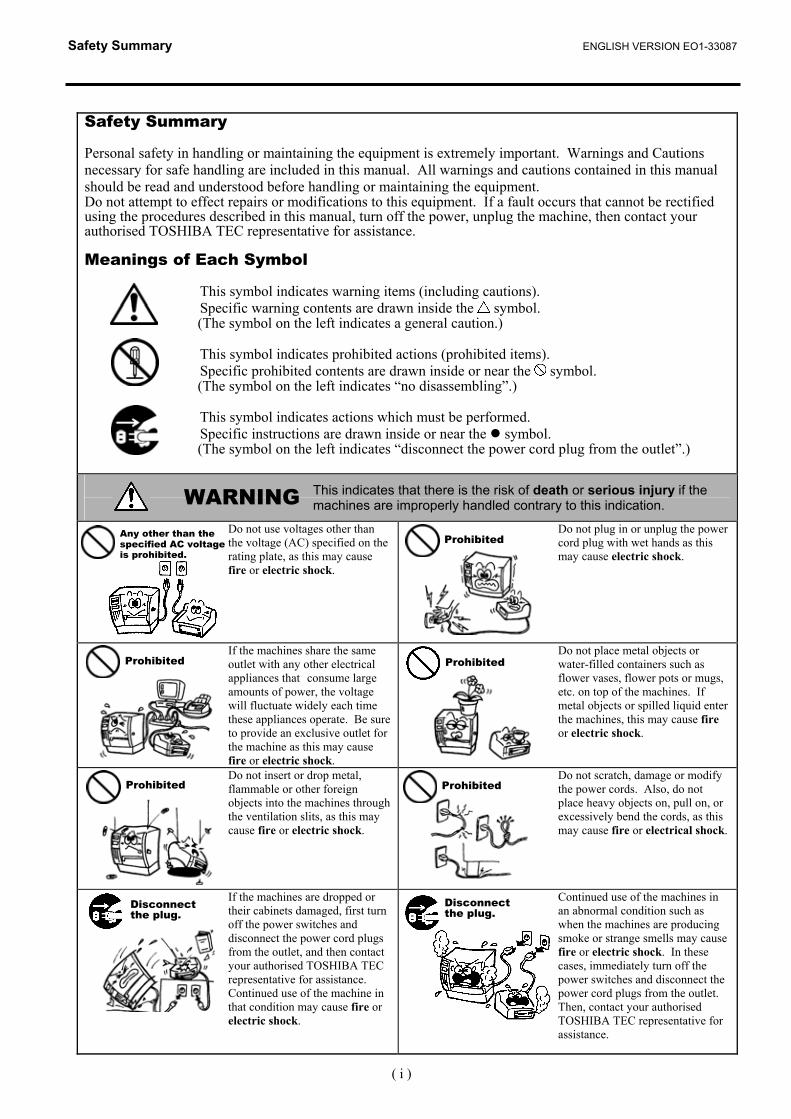
This symbol indicates warning items (including cautions). Specific warning contents are drawn inside the symbol. (The symbol on the left indicates a general caution.) This symbol indicates prohibited actions (prohibited items). Specific prohibited contents are drawn inside or near the symbol. (The symbol on the left indicates “no disassembling”.) This symbol indicates actions which must be performed. Specific instructions are drawn inside or near the symbol. (The symbol on the left indicates “disconnect the power cord plug from the outlet”.)
This indicates that there is the risk of death or serious injury if the machines are improperly handled contrary to this indication.
Do not use voltages other than the voltage (AC) specified on the rating plate, as this may cause fire or electric shock.
Do not plug in or unplug the power cord plug with wet hands as this may cause electric shock.
If the machines share the same outlet with any other electrical appliances that consume large amounts of power, the voltage will fluctuate widely each time these appliances operate. Be sure to provide an exclusive outlet for the machine as this may cause fire or electric shock.
Do not place metal objects or water-filled containers such as flower vases, flower pots or mugs, etc. on top of the machines. If metal objects or spilled liquid enter the machines, this may cause fire or electric shock.
Do not insert or drop metal, flammable or other foreign objects into the machines through the ventilation slits, as this may cause fire or electric shock.
Do not scratch, damage or modify the power cords. Also, do not place heavy objects on, pull on, or excessively bend the cords, as this may cause fire or electrical shock.
If the machines are dropped or their cabinets damaged, first turn off the power switches and disconnect the power cord plugs from the outlet, and then contact your authorised TOSHIBA TEC representative for assistance. Continued use of the machine in that condition may cause fire or electric shock.
Continued use of the machines in an abnormal condition such as when the machines are producing smoke or strange smells may cause fire or electric shock. In these cases, immediately turn off the power switches and disconnect the power cord plugs from the outlet. Then, contact your authorised TOSHIBA TEC representative for assistance.
WARNING
Any other than the specified AC voltage is prohibited.
Prohibited
Prohibited
Prohibited
Prohibited
Prohibited
Disconnect the plug.
Disconnect the plug.
Safety Summary ENGLISH VERSION EO1-33087
( ) ii
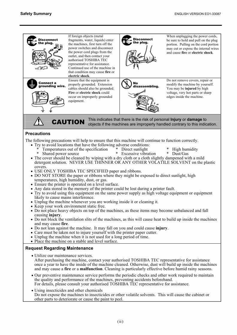
If foreign objects (metal fragments, water, liquids) enter the machines, first turn off the power switches and disconnect the power cord plugs from the outlet, and then contact your authorised TOSHIBA TEC representative for assistance. Continued use of the machine in that condition may cause fire or electric shock.
When unplugging the power cords, be sure to hold and pull on the plug portion. Pulling on the cord portion may cut or expose the internal wires and cause fire or electric shock.
Ensure that the equipment is properly grounded. Extension cables should also be grounded. Fire or electric shock could occur on improperly grounded equipment.
Do not remove covers, repair or modify the machine by yourself. You may be injured by high voltage, very hot parts or sharp edges inside the machine.
This indicates that there is the risk of personal Injury or damage to objects if the machines are improperly handled contrary to this indication.
Precautions The following precautions will help to ensure that this machine will continue to function correctly.
• Try to avoid locations that have the following adverse conditions: * Temperatures out of the specification * Direct sunlight * High humidity * Shared power source * Excessive vibration * Dust/Gas • The cover should be cleaned by wiping with a dry cloth or a cloth slightly dampened with a mild
detergent solution. NEVER USE THINNER OR ANY OTHER VOLATILE SOLVENT on the plastic covers.
• USE ONLY TOSHIBA TEC SPECIFIED paper and ribbons. • DO NOT STORE the paper or ribbons where they might be exposed to direct sunlight, high
temperatures, high humidity, dust, or gas. • Ensure the printer is operated on a level surface. • Any data stored in the memory of the printer could be lost during a printer fault. • Try to avoid using this equipment on the same power supply as high voltage equipment or equipment
likely to cause mains interference. • Unplug the machine whenever you are working inside it or cleaning it. • Keep your work environment static free. • Do not place heavy objects on top of the machines, as these items may become unbalanced and fall
causing injury. • Do not block the ventilation slits of the machines, as this will cause heat to build up inside the machines
and may cause fire. • Do not lean against the machine. It may fall on you and could cause injury. • Care must be taken not to injure yourself with the printer paper cutter. • Unplug the machine when it is not used for a long period of time. • Place the machine on a stable and level surface.
Request Regarding Maintenance • Utilize our maintenance services. After purchasing the machine, contact your authorised TOSHIBA TEC representative for assistance
once a year to have the inside of the machine cleaned. Otherwise, dust will build up inside the machines and may cause a fire or a malfunction. Cleaning is particularly effective before humid rainy seasons.
• Our preventive maintenance service performs the periodic checks and other work required to maintain the quality and performance of the machines, preventing accidents beforehand.
For details, please consult your authorised TOSHIBA TEC representative for assistance. • Using insecticides and other chemicals
Do not expose the machines to insecticides or other volatile solvents. This will cause the cabinet or other parts to deteriorate or cause the paint to peel.
CAUTION
Disconnect the plug.
Connect a grounding wire.
Disconnect the plug.
No disassembling.
ENGLISH VERSION EO1-33087
TABLE OF CONTENTS
Page 1. PRODUCT OVERVIEW.......................................................................................................... E1-1 1.1 Introduction.................................................................................................................... E1-1 1.2 Features ........................................................................................................................ E1-1 1.3 Unpacking...................................................................................................................... E1-1 1.4 Accessories .................................................................................................................. E1-1 1.5 Appearance ................................................................................................................... E1-3 1.5.1 Dimensions.................................................................................................................E1-3 1.5.2 Front View ..................................................................................................................E1-3 1.5.3 Rear View...................................................................................................................E1-3 1.5.4 Interior ........................................................................................................................E1-4 1.5.5 Button and Indicator Lamp .........................................................................................E1-5
2. PRINTER SETUP ................................................................................................................... E2-1 2.1 Precautions.................................................................................................................... E2-1 2.2 Procedure before Operation .......................................................................................... E2-2 2.3 Turning the Printer ON/OFF .......................................................................................... E2-2 2.3.1 Turning ON the Printer ...............................................................................................E2-2 2.3.2 Turning OFF the Printer..............................................................................................E2-3 2.4 Connecting the Cables to the Printer............................................................................. E2-4 2.5 Connecting the Power Adapter and the Power Cord..................................................... E2-5 2.6 Opening/Closing the Top Cover .................................................................................... E2-6 2.7 Loading the Media ......................................................................................................... E2-7 2.8 Loading the Ribbon ..................................................................................................... E2-14 2.9 Media Sensor Calibration, Self Print Test, and Dump Mode Utilities........................... E2-17 2.9.1 Media Sensor Calibration .........................................................................................E2-17 2.9.2 Self Print Test and Dump Mode................................................................................E2-18 2.10 How to Use an SD Card .....................................................................................................E2-20
3. MAINTENANCE ..................................................................................................................... E3-1 3.1 Cleaning ........................................................................................................................ E3-1 3.1.1 Print Head ..................................................................................................................E3-1 3.1.2 Platen/Sensors ...........................................................................................................E3-2 3.1.3 Cover..........................................................................................................................E3-2 3.1.4 Media Housing............................................................................................................E3-2 3.1.5 Strip Sensor/Strip Roller (Option) ...............................................................................E3-3 3.2 Care/Handling of the Media and Ribbon ....................................................................... E3-3
4. TROUBLESHOOTING ........................................................................................................... E4-1 4.1 Troubleshooting Guide .................................................................................................. E4-1 4.2 Status Lamp .................................................................................................................. E4-2 4.3 Removing Jammed Media............................................................................................. E4-3
APPENDIX 1 SPECIFICATIONS ................................................................................................EA1-1 A1.1 Printer .......................................................................................................................... EA1-1 A1.2 Options ........................................................................................................................ EA1-3 A1.3 Media........................................................................................................................... EA1-3 A1.3.1 Media Type ........................................................................................................... EA1-3 A1.3.2 Detection Area of the Transmissive Sensor .......................................................... EA1-4 A1.3.3 Detection Area of the Reflective Sensor ............................................................... EA1-5 A1.3.4 Effective Print Area ............................................................................................... EA1-6 A1.4 Ribbon ......................................................................................................................... EA1-6
ENGLISH VERSION EO1-33087
APPENDIX 2 INTERFACE..........................................................................................................EA2-1
GLOSSARIES
CAUTION! 1. This manual may not be copied in whole or in part without prior written permission of TOSHIBA TEC. 2. The contents of this manual may be changed without notification. 3. Please refer to your local Authorized Service representative with regard to any queries you may have in
this manual.
1. PRODUCT OVERVIEW ENGLISH VERSION EO1-33087
1.1 Introduction
E1- 1
1. PRODUCT OVERVIEW1.1 Introduction 1.2 Features 1.3 Unpacking 1.4 Accessories
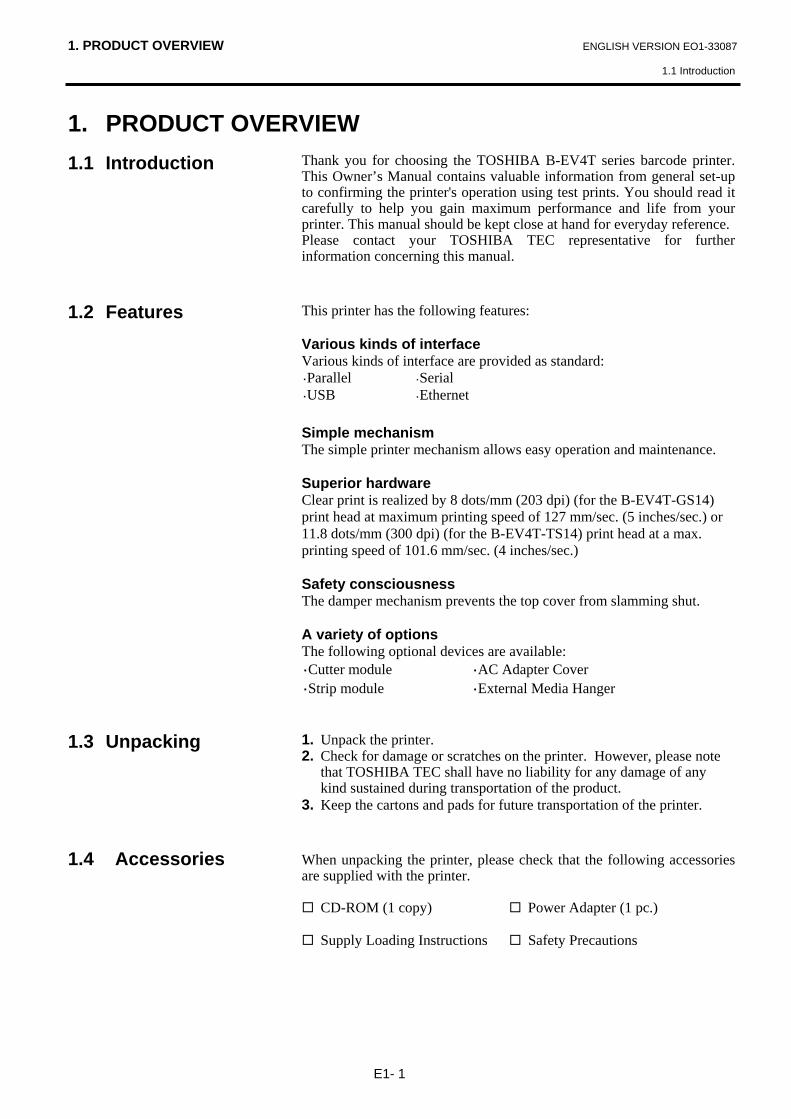
Thank you for choosing the TOSHIBA B-EV4T series barcode printer. This Owner’s Manual contains valuable information from general set-up to confirming the printer's operation using test prints. You should read it carefully to help you gain maximum performance and life from your printer. This manual should be kept close at hand for everyday reference. Please contact your TOSHIBA TEC representative for further information concerning this manual. This printer has the following features: Various kinds of interface Various kinds of interface are provided as standard: ・Parallel ・Serial ・USB ・Ethernet Simple mechanism The simple printer mechanism allows easy operation and maintenance. Superior hardware Clear print is realized by 8 dots/mm (203 dpi) (for the B-EV4T-GS14) print head at maximum printing speed of 127 mm/sec. (5 inches/sec.) or 11.8 dots/mm (300 dpi) (for the B-EV4T-TS14) print head at a max. printing speed of 101.6 mm/sec. (4 inches/sec.) Safety consciousness The damper mechanism prevents the top cover from slamming shut. A variety of options The following optional devices are available: ・Cutter module ・AC Adapter Cover ・Strip module ・External Media Hanger 1. Unpack the printer. 2. Check for damage or scratches on the printer. However, please note
that TOSHIBA TEC shall have no liability for any damage of any kind sustained during transportation of the product.
3. Keep the cartons and pads for future transportation of the printer. When unpacking the printer, please check that the following accessories are supplied with the printer.
CD-ROM (1 copy) Power Adapter (1 pc.)
Supply Loading Instructions Safety Precautions
1. PRODUCT OVERVIEW ENGLISH VERSION EO1-33087
1.4 Accessories
E1- 2
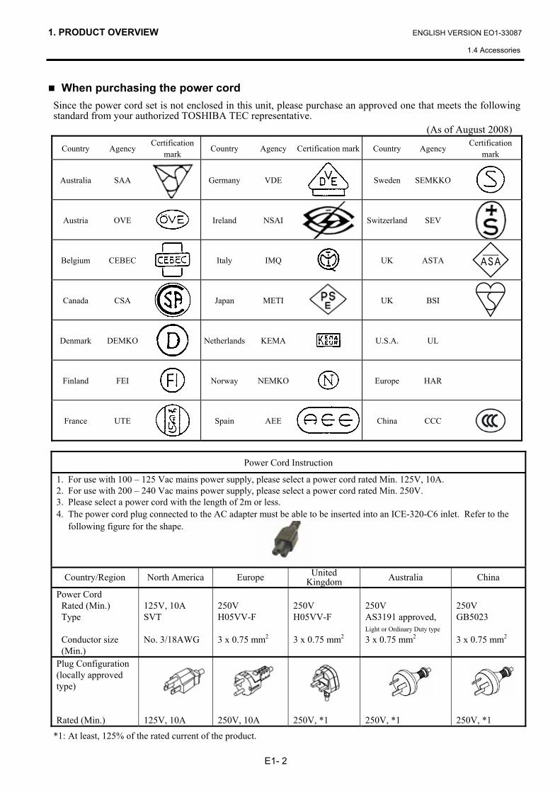
When purchasing the power cord Since the power cord set is not enclosed in this unit, please purchase an approved one that meets the following standard from your authorized TOSHIBA TEC representative.
(As of August 2008)
Country Agency Certification
mark Country Agency Certification mark Country Agency
Certification mark
Australia SAA Germany VDE
Sweden SEMKKO
Austria OVE
Ireland NSAI Switzerland SEV
Belgium CEBEC
Italy IMQ
UK ASTA
Canada CSA
Japan METI
UK BSI
Denmark DEMKO
Netherlands KEMA U.S.A. UL
Finland FEI
Norway NEMKO
Europe HAR
France UTE
Spain AEE China CCC
Power Cord Instruction
1. For use with 100 – 125 Vac mains power supply, please select a power cord rated Min. 125V, 10A. 2. For use with 200 – 240 Vac mains power supply, please select a power cord rated Min. 250V. 3. Please select a power cord with the length of 2m or less. 4. The power cord plug connected to the AC adapter must be able to be inserted into an ICE-320-C6 inlet. Refer to the
following figure for the shape.
Country/Region North America Europe United Kingdom Australia China
Power Cord Rated (Min.) Type Conductor size (Min.)
125V, 10A SVT No. 3/18AWG
250V H05VV-F 3 x 0.75 mm2
250V H05VV-F 3 x 0.75 mm2
250V AS3191 approved, Light or Ordinary Duty type
3 x 0.75 mm2
250V GB5023 3 x 0.75 mm2
Plug Configuration (locally approved type) Rated (Min.)
125V, 10A
250V, 10A
250V, *1
250V, *1
250V, *1
*1: At least, 125% of the rated current of the product.
1. PRODUCT OVERVIEW ENGLISH VERSION EO1-33087
1.5 Appearance
E1- 3
1.5 Appearance 1.5.1 Dimensions 1.5.2 Front View 1.5.3 Rear View
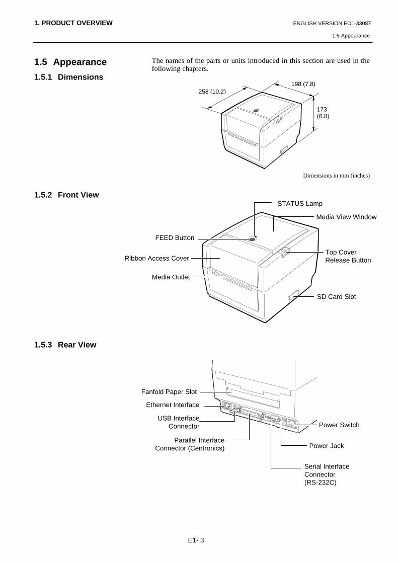
The names of the parts or units introduced in this section are used in the following chapters.
Dimensions in mm (inches)
Power Jack
Power Switch
Fanfold Paper Slot
Parallel InterfaceConnector (Centronics)
USB InterfaceConnector
Serial Interface Connector (RS-232C)
198 (7.8) 258 (10.2)
173 (6.8)
Top Cover Release Button
FEED Button
Media Outlet
STATUS Lamp
Ribbon Access Cover
Media View Window
Ethernet Interface
SD Card Slot
1. PRODUCT OVERVIEW ENGLISH VERSION EO1-33087
1.5 Appearance
E1- 4
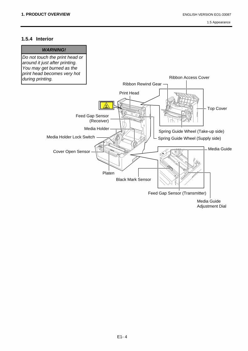
1.5.4 Interior
WARNING! Do not touch the print head or around it just after printing. You may get burned as the print head becomes very hot during printing.
Ribbon Rewind Gear
Media Guide
Media Holder Lock Switch
Black Mark Sensor
Cover Open Sensor
Feed Gap Sensor(Receiver)
Media Guide Adjustment Dial
Print Head
Media Holder
Top Cover
Platen
Spring Guide Wheel (Take-up side)
Spring Guide Wheel (Supply side)
Feed Gap Sensor (Transmitter)
Ribbon Access Cover
1. PRODUCT OVERVIEW ENGLISH VERSION EO1-33035
1.5 Appearance
E1- 5
1.5.5 Button and Indicator Lamp
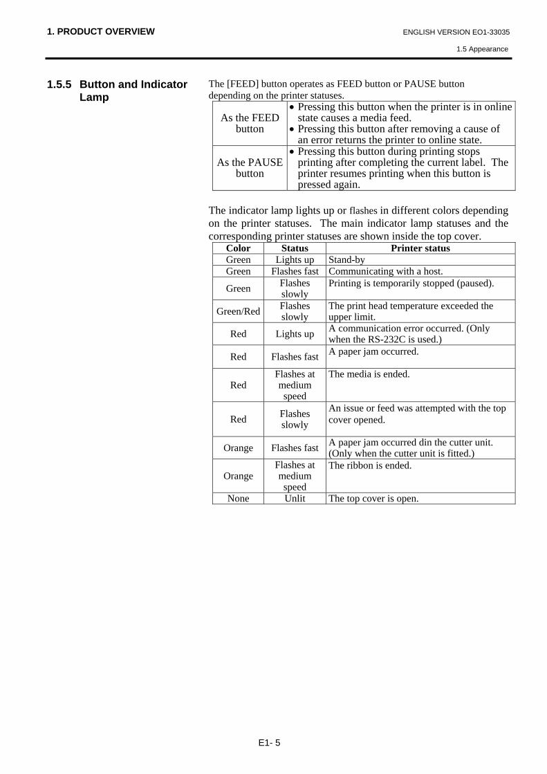
The [FEED] button operates as FEED button or PAUSE button depending on the printer statuses.
As the FEED button
• Pressing this button when the printer is in online state causes a media feed.
• Pressing this button after removing a cause of an error returns the printer to online state.
As the PAUSE button
• Pressing this button during printing stops printing after completing the current label. The printer resumes printing when this button is pressed again.
The indicator lamp lights up or flashes in different colors depending on the printer statuses. The main indicator lamp statuses and the corresponding printer statuses are shown inside the top cover.
Color Status Printer status Green Lights up Stand-by Green Flashes fast Communicating with a host.
Green Flashes slowly
Printing is temporarily stopped (paused).
Green/Red Flashes slowly
The print head temperature exceeded the upper limit.
Red Lights up A communication error occurred. (Only when the RS-232C is used.)
Red Flashes fast A paper jam occurred.
Red Flashes at medium speed
The media is ended.
Red Flashes slowly
An issue or feed was attempted with the top cover opened.
Orange Flashes fast A paper jam occurred din the cutter unit. (Only when the cutter unit is fitted.)
Orange Flashes at medium speed
The ribbon is ended.
None Unlit The top cover is open.
2. PRINTER SETUP ENGLISH VERSION EO1-33087
2.1 Precautions
E2- 1
2. PRINTER SETUP 2.1 Precautions
This section outlines the steps necessary to setup your printer prior to its operation. The section includes precautions, connecting cables, assembling accessories, loading media and ribbon, and performing a test print. To insure the best operating environment, and to assure the safety of the operator and the equipment, please observe the following precautions. • Operate the printer on a stable, level, operating surface in a location
free from excessive humidity, high temperature, dust, vibration or direct sunlight.
• Keep your work environment static free. Static discharges can cause damage to delicate internal components.
• Make sure that the printer is connected to a clean source of AC Power and that no other high voltage devices that may cause line noise interference are connected to the same mains.
• Ensure that the printer is connected only to AC mains that has a proper ground (earth) connection.
• Do not operate the printer with the cover open. Be careful not to allow fingers or articles of clothing to get caught into any of the moving parts of the printer.
• Make sure to turn off the printer power and to remove the power adapter connector from the printer whenever working on the inside of the printer or when cleaning the printer.
• For best results, and longer printer life, use only TOSHIBA TEC recommended media and ribbon. (Refer to the Supply Manual.)
• Store the media and ribbon in accordance with the specifications. • This printer mechanism contains high voltage components; therefore
you should never remove any of the covers of the machine as you may receive an electrical shock. Additionally, the printer contains many delicate components that may be damaged if accessed by unauthorized personnel.
• Clean the outside of the printer with a clean dry cloth or a clean cloth slightly dampened with a mild detergent solution.
• Use caution when cleaning the thermal print head as it may become very hot while printing. Wait until it has had time to cool before cleaning. Use only the TOSHIBA TEC recommended print head cleaner to clean the print head.
• Do not turn off the printer power or remove the power plug while the printer is printing or while the Indictor Lamp is flashing.
CAUTION! Avoid using the printer in the locations where it is subjected to intense light (e.g. direct sunlight, desk light). Such light may affect the sensors of the printer, causing malfunctions.
2. PRINTER SETUP ENGLISH VERSION EO1-33087
2.2 Procedure before Operation
E2- 2
2.2 Procedure before Operation
2.3 Turning the Printer ON/OFF
2.3.1 Turning ON the Printer
This section describes the outline of the printer setup.
1. Unpack the accessories and printer from the box. 2. Refer to Safety Precautions in this manual and set up the printer at a
proper location. 3. Make sure that the Power Switch is off. (Refer to Section 2.3.) 4. Connect the printer to a host computer with an RS-232C, Centronics
interface, Ethernet cable or USB cable. (Refer to Section 2.4.) 5. Connect the Power Adapter to the printer, and then plug the Power
Cord into a properly grounded power outlet. (Refer to Section 2.5) 6. Load the media. (Refer to Section 2.7.) 7. Adjust the position of the Feed Gap Sensor or Black Mark Sensor to
match the media being used. (Refer to Section 2.7.) 8. Load the ribbon. (Refer to Section 2.8) 9. Turn the Power ON. (Refer to Section 2.3.) 10. Install the Printer Drivers in the host computer. (Refer to the Printer
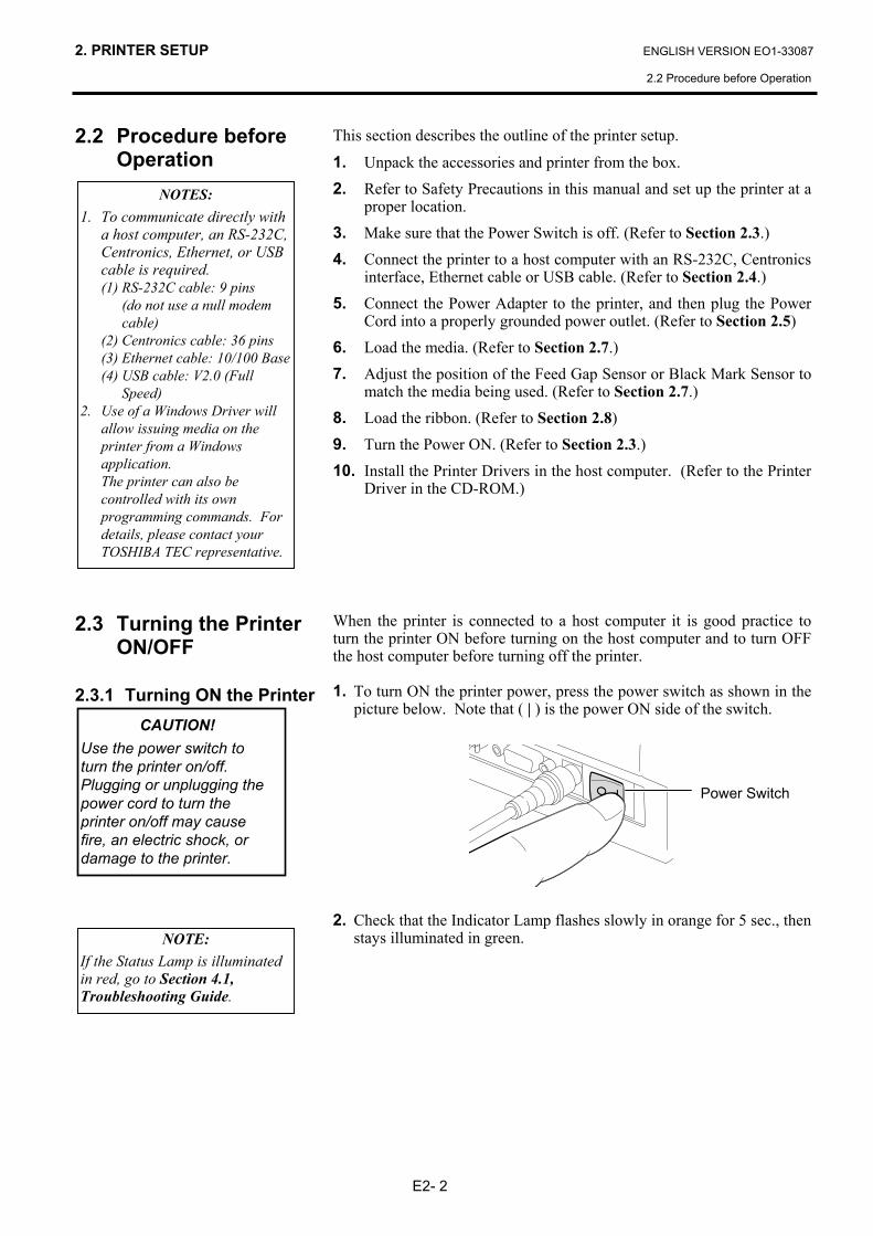
Driver in the CD-ROM.) When the printer is connected to a host computer it is good practice to turn the printer ON before turning on the host computer and to turn OFF the host computer before turning off the printer. 1. To turn ON the printer power, press the power switch as shown in the
picture below. Note that ( | ) is the power ON side of the switch.
2. Check that the Indicator Lamp flashes slowly in orange for 5 sec., then
stays illuminated in green.
NOTES: 1. To communicate directly with
a host computer, an RS-232C, Centronics, Ethernet, or USB cable is required. (1) RS-232C cable: 9 pins
(do not use a null modem cable)
(2) Centronics cable: 36 pins (3) Ethernet cable: 10/100 Base (4) USB cable: V2.0 (Full
Speed) 2. Use of a Windows Driver will
allow issuing media on the printer from a Windows application.
The printer can also be controlled with its own programming commands. For details, please contact your TOSHIBA TEC representative.
CAUTION! Use the power switch to turn the printer on/off. Plugging or unplugging the power cord to turn the printer on/off may cause fire, an electric shock, or damage to the printer.
NOTE: If the Status Lamp is illuminated in red, go to Section 4.1, Troubleshooting Guide.
Power Switch
2. PRINTER SETUP ENGLISH VERSION EO1-33087
2.4 Connecting the Cables to the Printer
E2- 3
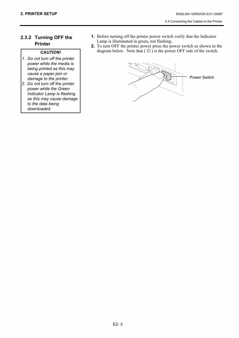
2.3.2 Turning OFF the Printer
1. Before turning off the printer power switch verify that the Indicator Lamp is illuminated in green, not flashing. 2. To turn OFF the printer power press the power switch as shown in the
diagram below. Note that ( ) is the power OFF side of the switch.
CAUTION! 1. Do not turn off the printer
power while the media is being printed as this may cause a paper jam or damage to the printer.
2. Do not turn off the printer power while the Green Indicator Lamp is flashing as this may cause damage to the data being downloaded.
Power Switch
2. PRINTER SETUP ENGLISH VERSION EO1-33087
2.4 Connecting the Cables to the Printer
E2- 4
2.4 Connecting the Cables to the Printer
The following paragraphs outline how to connect the cables from the printer to your host computer, and will also show how to make cable connections to other devices. Depending on the application software you use to print labels, there are four possibilities for connecting the printer to your host computer. These are:
• A serial cable connection between the printer’s RS-232C serial connector and one of your host computer’s COM ports.
• A parallel cable connection between the printer’s standard parallel connector and your host computer’s parallel port (LPT).
• An Ethernet cable connection between the printer’s Ethernet interface connector and one of your host computer’s Ethernet port. NOTE: ▪ Use an Ethernet cable conforming to the standard.
10BASE-T: Category 3 or greater 100BASE-TX: Category 5 or greater Cable length: Up to 100 m segment length
▪ Depending on the operating environment, a communication error may occur. In that case, you may need to use a shielded cable (STP) or device matching.
• A USB cable connection between the printer’s USB interface connector and one of your host computer’s USB port. NOTE: ▪ When disconnecting the USB cable from the host computer,
follow the “Safely remove hardware” message shown on the host. ▪ Use a USB cable confirming to V1.1 or greater and with a Type
B connecter provided on either end.
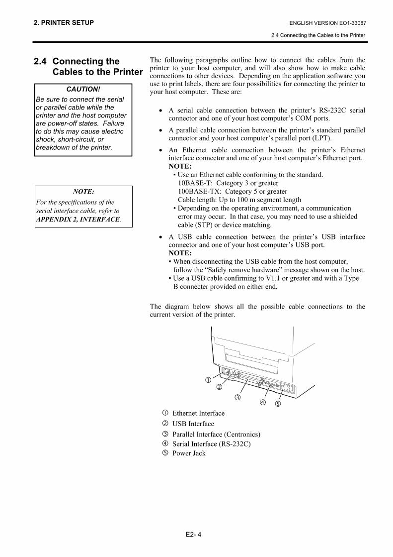
The diagram below shows all the possible cable connections to the current version of the printer.
Ethernet Interface USB Interface Parallel Interface (Centronics) Serial Interface (RS-232C) Power Jack
NOTE: For the specifications of the serial interface cable, refer to APPENDIX 2, INTERFACE.
CAUTION! Be sure to connect the serial or parallel cable while the printer and the host computer are power-off states. Failure to do this may cause electric shock, short-circuit, or breakdown of the printer.
2. PRINTER SETUP ENGLISH VERSION EO1-33087
2.5 Connecting the Power Adapter and the Power Cord
E2- 5
2.5 Connecting the Power Adapter and the Power Cord
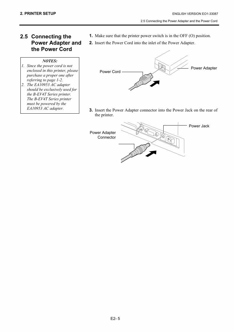
1. Make sure that the printer power switch is in the OFF (O) position. 2. Insert the Power Cord into the inlet of the Power Adapter.
3. Insert the Power Adapter connector into the Power Jack on the rear of
the printer.
Power Adapter Power Cord
Power AdapterConnector
Power Jack
NOTES: 1. Since the power cord is not
enclosed in this printer, please purchase a proper one after referring to page 1-2.
2. The EA10953 AC adapter should be exclusively used for the B-EV4T Series printer. The B-EV4T Series printer must be powered by the EA10953 AC adapter.
2. PRINTER SETUP ENGLISH VERSION EO1-33087
2.6 Opening/Closing the Top Cover
E2- 6
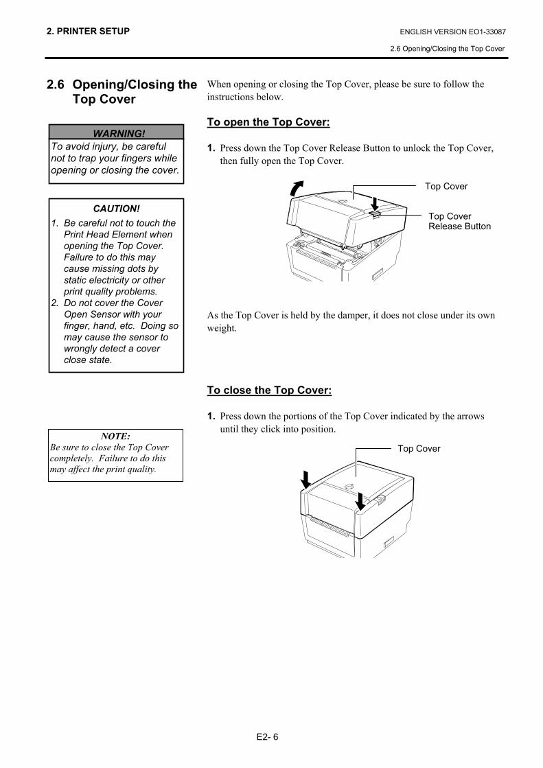
2.6 Opening/Closing the Top Cover
When opening or closing the Top Cover, please be sure to follow the instructions below. To open the Top Cover: 1. Press down the Top Cover Release Button to unlock the Top Cover,
then fully open the Top Cover.
As the Top Cover is held by the damper, it does not close under its own weight.
To close the Top Cover: 1. Press down the portions of the Top Cover indicated by the arrows
until they click into position.
WARNING! To avoid injury, be careful not to trap your fingers while opening or closing the cover.
CAUTION! 1. Be careful not to touch the
Print Head Element when opening the Top Cover. Failure to do this may cause missing dots by static electricity or other print quality problems.
2. Do not cover the Cover Open Sensor with your finger, hand, etc. Doing so may cause the sensor to wrongly detect a cover close state.
Top Cover
Top CoverRelease Button
Top Cover
NOTE: Be sure to close the Top Cover completely. Failure to do this may affect the print quality.
2. PRINTER SETUP ENGLISH VERSION EO1-33087
2.7 Loading the Media
E2- 7
2.7 Loading the Media
This section describes how to load a media in the printer. This printer accepts label rolls, tag rolls, and fanfold paper stocks. Please use TOSHIBA TEC approved media. NOTES:
1. Please perform a media sensor calibration whenever you change the media type.
2. The size of the media which can be loaded inside the printer is as
follows: Outer roll diameter: Max. 127mm (5”) Inner core diameter: 25.4 (1”) mm or 38.1 mm (1.5”)
When the outer roll diameter exceeds 127 mm or the inner core diameter exceeds 38.1 mm, an optional External Media Roll Hanger is required. For details, refer to the Installation Guide for the External Media Roll Hanger.
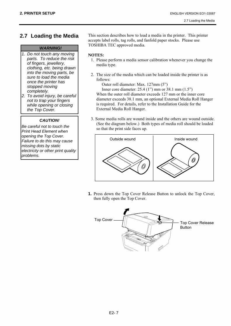
3. Some media rolls are wound inside and the others are wound outside. (See the diagram below.) Both types of media roll should be loaded so that the print side faces up.
1. Press down the Top Cover Release Button to unlock the Top Cover,
then fully open the Top Cover.
WARNING! 1. Do not touch any moving
parts. To reduce the risk of fingers, jewellery, clothing, etc. being drawn into the moving parts, be sure to load the media once the printer has stopped moving completely.
2. To avoid injury, be careful not to trap your fingers while opening or closing the Top Cover.
CAUTION! Be careful not to touch the Print Head Element when opening the Top Cover. Failure to do this may cause missing dots by static electricity or other print quality problems.
Top Cover Release Button
Top Cover
Outside wound Inside wound
2. PRINTER SETUP ENGLISH VERSION EO1-33087
2.7 Loading the Media
E2- 8
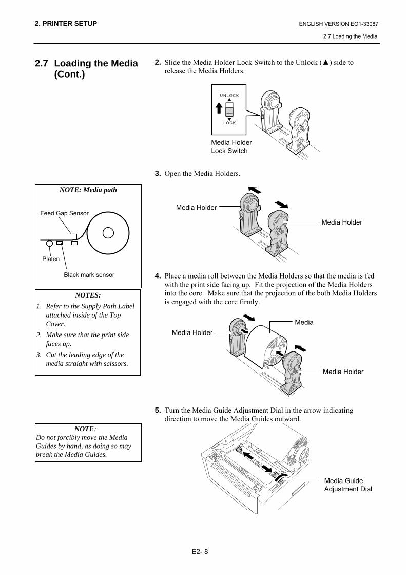
2.7 Loading the Media (Cont.)
2. Slide the Media Holder Lock Switch to the Unlock (▲) side to release the Media Holders.
3. Open the Media Holders.
4. Place a media roll between the Media Holders so that the media is fed
with the print side facing up. Fit the projection of the Media Holders into the core. Make sure that the projection of the both Media Holders is engaged with the core firmly.
5. Turn the Media Guide Adjustment Dial in the arrow indicating
direction to move the Media Guides outward.
Media Holder
Media Holder
NOTE: Media path
Platen
Feed Gap Sensor
Black mark sensor
Media HolderMedia
NOTES: 1. Refer to the Supply Path Label
attached inside of the Top Cover.
2. Make sure that the print side faces up.
3. Cut the leading edge of the media straight with scissors.
Media Guide Adjustment Dial
NOTE: Do not forcibly move the Media Guides by hand, as doing so may break the Media Guides.
Media Holder Lock Switch
Media Holder
2. PRINTER SETUP ENGLISH VERSION EO1-33087
2.7 Loading the Media
E2- 9
2.7 Loading the Media (Cont.)
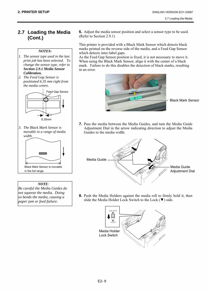
6. Adjust the media sensor position and select a sensor type to be used. (Refer to Section 2.9.1) This printer is provided with a Black Mark Sensor which detects black marks printed on the reverse side of the media, and a Feed Gap Sensor which detects inter-label gaps. As the Feed Gap Sensor position is fixed, it is not necessary to move it. When using the Black Mark Sensor, align it with the center of a black mark. Failure to do this disables the detection of black marks, resulting in an error.
7. Pass the media between the Media Guides, and turn the Media Guide
Adjustment Dial in the arrow indicating direction to adjust the Media Guides to the media width.
8. Push the Media Holders against the media roll to firmly hold it, then
slide the Media Holder Lock Switch to the Lock (▼) side.
Media Guide
NOTE: Be careful the Media Guides do not squeeze the media. Doing so bends the media, causing a paper jam or feed failure.
Black Mark Sensor
NOTES: 1. The sensor type used in the last
print job has been selected. To change the sensor type, refer to Section 2.9.1 Media Sensor Calibration.
2. The Feed Gap Sensor is positioned 6.35 mm right from the media centre.
3. The Black Mark Sensor is
movable in a range of media width.
Feed Gap Sensor
Black Mark Sensor is movable in the full range.
6.35mm
Media Guide Adjustment Dial
Media Holder Lock Switch
2. PRINTER SETUP ENGLISH VERSION EO1-33087
2.7 Loading the Media
E2-10
2.7 Loading the Media (Cont.)
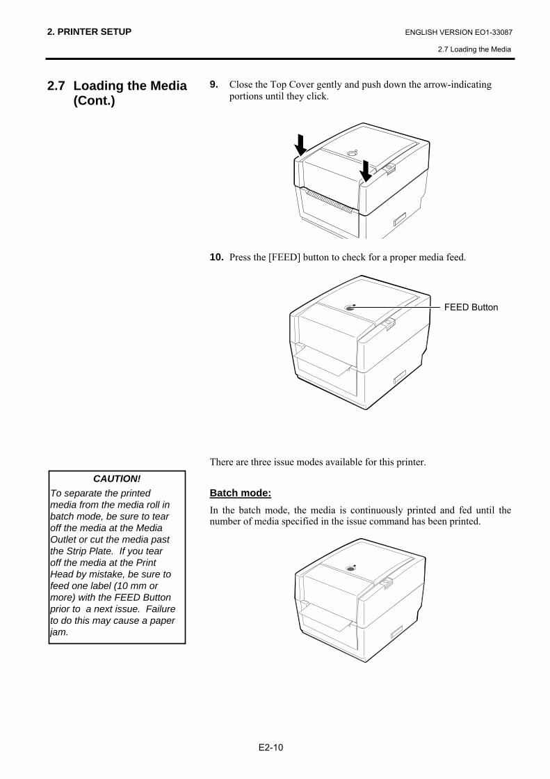
9. Close the Top Cover gently and push down the arrow-indicating portions until they click.
10. Press the [FEED] button to check for a proper media feed.
There are three issue modes available for this printer.
Batch mode: In the batch mode, the media is continuously printed and fed until the number of media specified in the issue command has been printed.
FEED Button
CAUTION! To separate the printed media from the media roll in batch mode, be sure to tear off the media at the Media Outlet or cut the media past the Strip Plate. If you tear off the media at the Print Head by mistake, be sure to feed one label (10 mm or more) with the FEED Button prior to a next issue. Failure to do this may cause a paper jam.
2. PRINTER SETUP ENGLISH VERSION EO1-33087
2.7 Loading the Media
E2-11
NOTES: 1. When issuing labels without
removing them from the backing paper, it is not necessary to pass the media through the Strip Block.
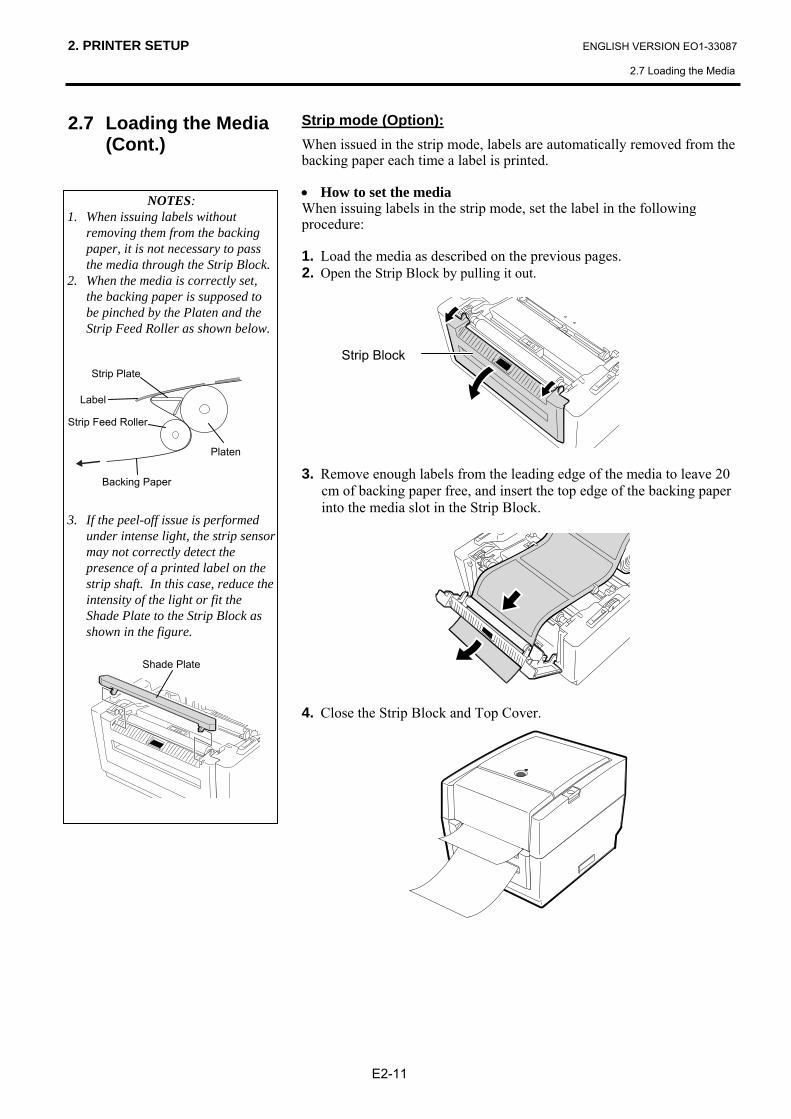
2. When the media is correctly set, the backing paper is supposed to be pinched by the Platen and the Strip Feed Roller as shown below.
3. If the peel-off issue is performed
under intense light, the strip sensor may not correctly detect the presence of a printed label on the strip shaft. In this case, reduce the intensity of the light or fit the Shade Plate to the Strip Block as shown in the figure.
Shade Plate
Strip Feed Roller
2.7 Loading the Media (Cont.)
Strip mode (Option): When issued in the strip mode, labels are automatically removed from the backing paper each time a label is printed. • How to set the media When issuing labels in the strip mode, set the label in the following procedure: 1. Load the media as described on the previous pages. 2. Open the Strip Block by pulling it out.
3. Remove enough labels from the leading edge of the media to leave 20
cm of backing paper free, and insert the top edge of the backing paper into the media slot in the Strip Block.
4. Close the Strip Block and Top Cover.
Strip Block Strip Plate
Label
Backing Paper
Platen
2. PRINTER SETUP ENGLISH VERSION EO1-33087
2.7 Loading the Media
E2-12
2.7 Loading the Media (Cont.)
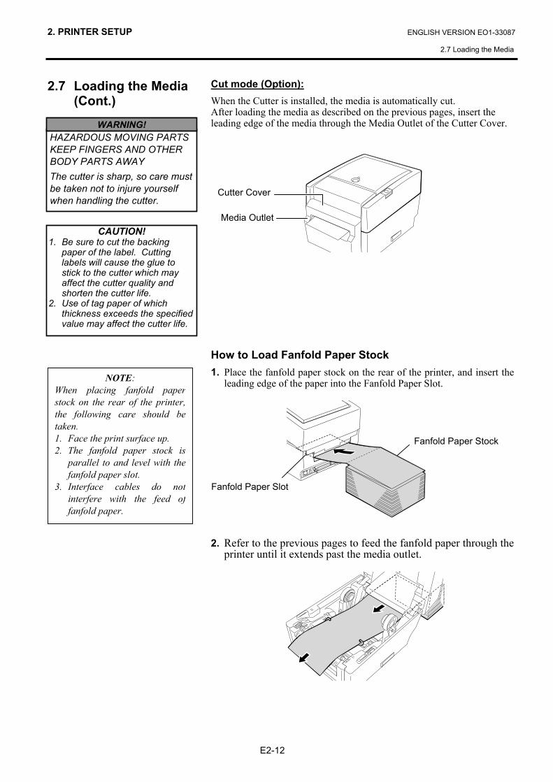
Cut mode (Option): When the Cutter is installed, the media is automatically cut. After loading the media as described on the previous pages, insert the leading edge of the media through the Media Outlet of the Cutter Cover.
How to Load Fanfold Paper Stock 1. Place the fanfold paper stock on the rear of the printer, and insert the
leading edge of the paper into the Fanfold Paper Slot.
2. Refer to the previous pages to feed the fanfold paper through the
printer until it extends past the media outlet.
CAUTION! 1. Be sure to cut the backing
paper of the label. Cutting labels will cause the glue to stick to the cutter which may affect the cutter quality and shorten the cutter life.
2. Use of tag paper of which thickness exceeds the specified value may affect the cutter life.
HAZARDOUS MOVING PARTS KEEP FINGERS AND OTHER BODY PARTS AWAY The cutter is sharp, so care must be taken not to injure yourself when handling the cutter.
WARNING!
Media Outlet
Cutter Cover
Fanfold Paper Stock
Fanfold Paper Slot
NOTE: When placing fanfold paperstock on the rear of the printer,the following care should betaken. 1. Face the print surface up. 2. The fanfold paper stock is
parallel to and level with thefanfold paper slot.
3. Interface cables do notinterfere with the feed offanfold paper.
2. PRINTER SETUP ENGLISH VERSION EO1-33087
2.7 Loading the Media
E2-13
2.7 Loading the Media (Cont.)
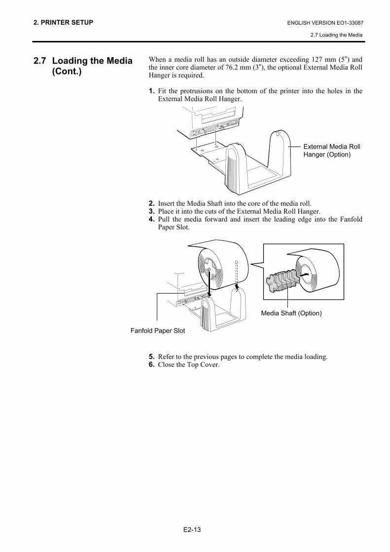
When a media roll has an outside diameter exceeding 127 mm (5”) and the inner core diameter of 76.2 mm (3”), the optional External Media Roll Hanger is required. 1. Fit the protrusions on the bottom of the printer into the holes in the
External Media Roll Hanger.
2. Insert the Media Shaft into the core of the media roll. 3. Place it into the cuts of the External Media Roll Hanger. 4. Pull the media forward and insert the leading edge into the Fanfold
Paper Slot.
5. Refer to the previous pages to complete the media loading. 6. Close the Top Cover.
External Media Roll Hanger (Option)
Media Shaft (Option)
Fanfold Paper Slot
2. PRINTER SETUP ENGLISH VERSION EO1-33087
2.8 Loading the Ribbon
E2-14
2.8 Loading the Ribbon
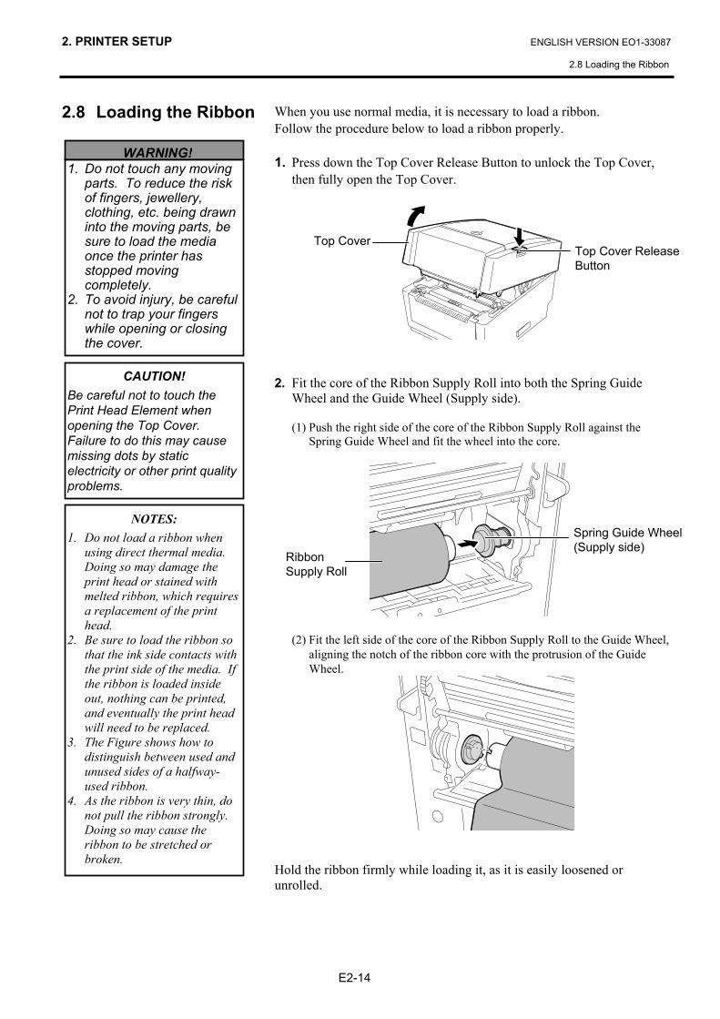
When you use normal media, it is necessary to load a ribbon. Follow the procedure below to load a ribbon properly. 1. Press down the Top Cover Release Button to unlock the Top Cover,
then fully open the Top Cover.
2. Fit the core of the Ribbon Supply Roll into both the Spring Guide
Wheel and the Guide Wheel (Supply side). (1) Push the right side of the core of the Ribbon Supply Roll against the
Spring Guide Wheel and fit the wheel into the core.
(2) Fit the left side of the core of the Ribbon Supply Roll to the Guide Wheel,
aligning the notch of the ribbon core with the protrusion of the Guide Wheel.
Hold the ribbon firmly while loading it, as it is easily loosened or unrolled.
WARNING! 1. Do not touch any moving
parts. To reduce the risk of fingers, jewellery, clothing, etc. being drawn into the moving parts, be sure to load the media once the printer has stopped moving completely.
2. To avoid injury, be careful not to trap your fingers while opening or closing the cover.
CAUTION! Be careful not to touch the Print Head Element when opening the Top Cover. Failure to do this may cause missing dots by static electricity or other print quality problems.
Top Cover Release Button
Ribbon Supply Roll
Top Cover
NOTES: 1. Do not load a ribbon when
using direct thermal media. Doing so may damage the print head or stained with melted ribbon, which requires a replacement of the print head.
2. Be sure to load the ribbon so that the ink side contacts with the print side of the media. If the ribbon is loaded inside out, nothing can be printed, and eventually the print head will need to be replaced.
3. The Figure shows how to distinguish between used and unused sides of a halfway-used ribbon.
4. As the ribbon is very thin, do not pull the ribbon strongly. Doing so may cause the ribbon to be stretched or broken.
Spring Guide Wheel (Supply side)
2. PRINTER SETUP ENGLISH VERSION EO1-33087
2.8 Loading the Ribbon
E2-15
2.8 Loading the Ribbon (Cont.)
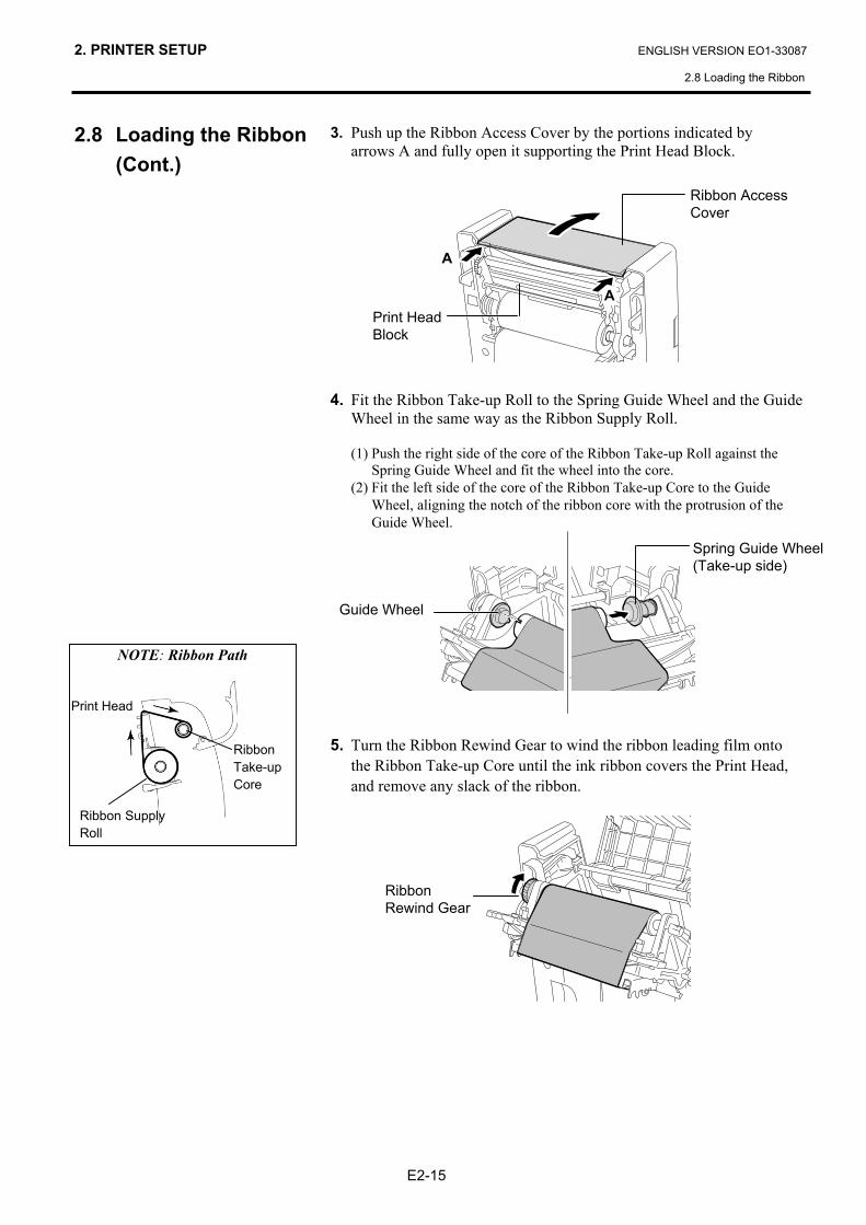
3. Push up the Ribbon Access Cover by the portions indicated by arrows A and fully open it supporting the Print Head Block.
4. Fit the Ribbon Take-up Roll to the Spring Guide Wheel and the Guide
Wheel in the same way as the Ribbon Supply Roll. (1) Push the right side of the core of the Ribbon Take-up Roll against the
Spring Guide Wheel and fit the wheel into the core. (2) Fit the left side of the core of the Ribbon Take-up Core to the Guide
Wheel, aligning the notch of the ribbon core with the protrusion of the Guide Wheel.
5. Turn the Ribbon Rewind Gear to wind the ribbon leading film onto
the Ribbon Take-up Core until the ink ribbon covers the Print Head, and remove any slack of the ribbon.
Ribbon Access Cover
Print Head Block
Guide Wheel
Spring Guide Wheel (Take-up side)
Ribbon Rewind Gear
NOTE: Ribbon Path
A
A
Ribbon Take-up Core
Ribbon SupplyRoll
Print Head
2. PRINTER SETUP ENGLISH VERSION EO1-33087
2.8 Loading the Ribbon
E2-16
2.8 Loading the Ribbon (Cont.)
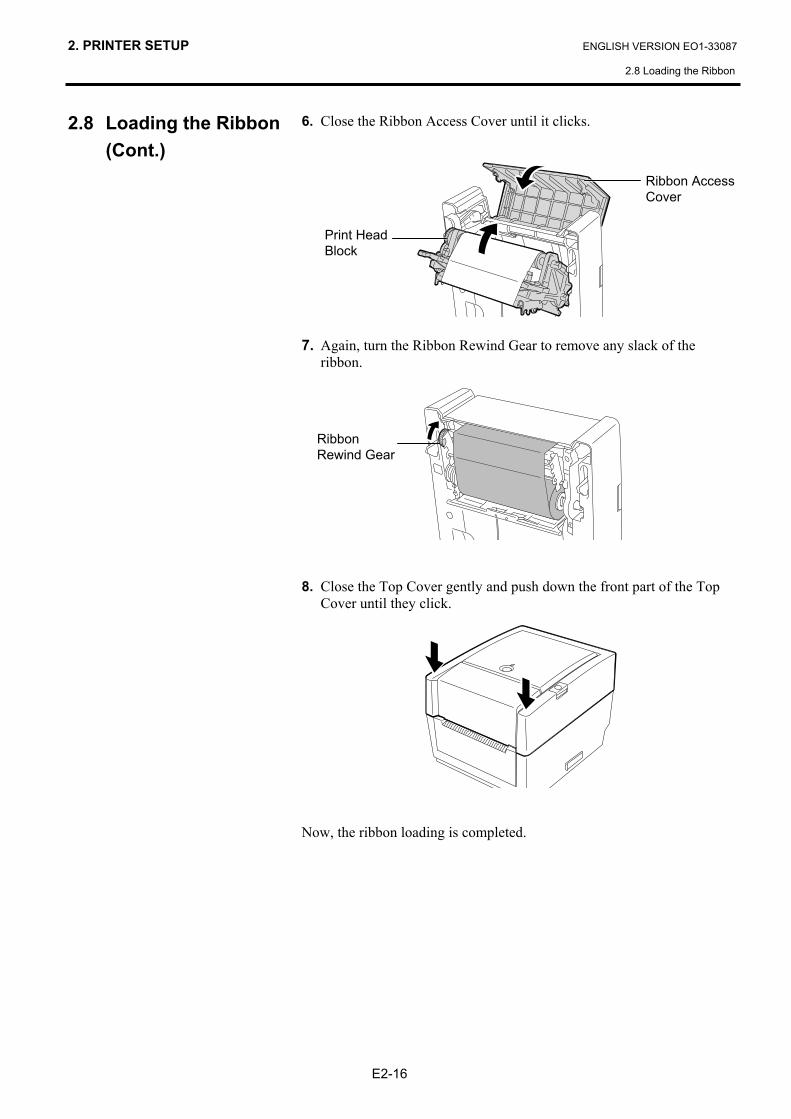
6. Close the Ribbon Access Cover until it clicks.
7. Again, turn the Ribbon Rewind Gear to remove any slack of the
ribbon.
8. Close the Top Cover gently and push down the front part of the Top
Cover until they click.
Now, the ribbon loading is completed.
Ribbon Access Cover
Print Head Block
Ribbon Rewind Gear
2. PRINTER SETUP ENGLISH VERSION EO1-33087
2.9 Media Sensor Calibration, Self Print Test, and Dump Mode Utilities
E2-17
2.9 Media Sensor Calibration, Self Print Test, and Dump Mode Utilities
2.9.1 Media Sensor
Calibration
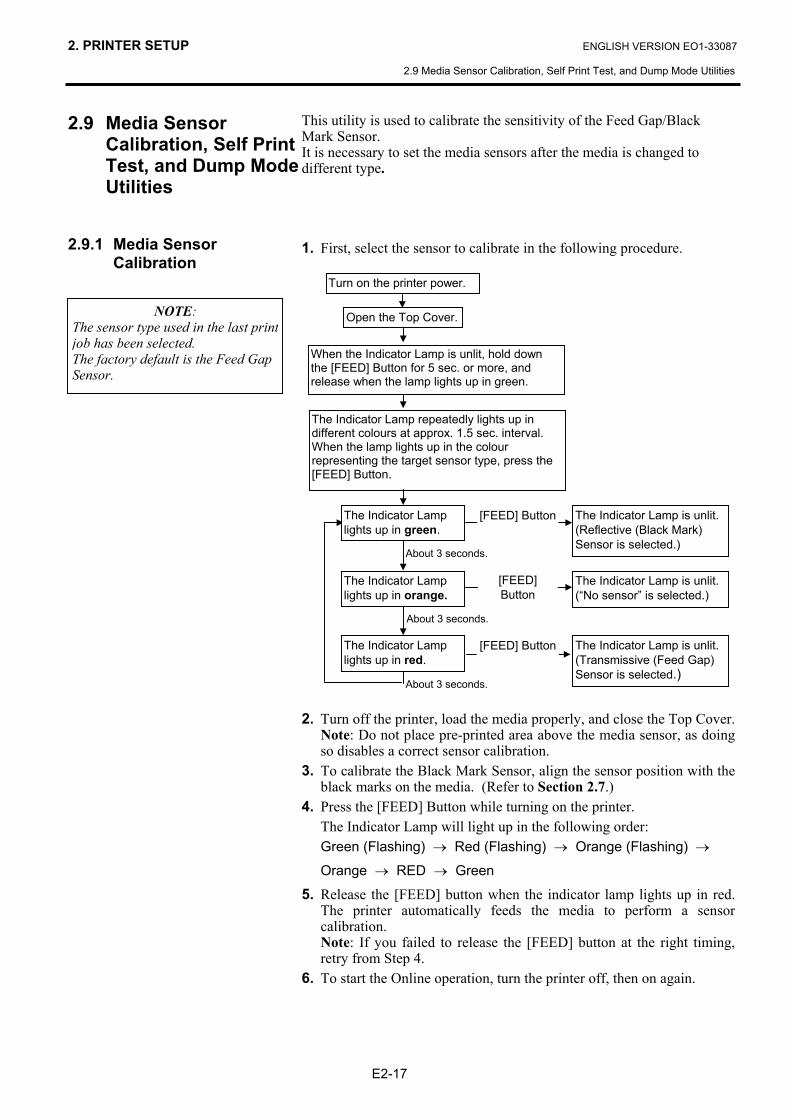
This utility is used to calibrate the sensitivity of the Feed Gap/Black Mark Sensor. It is necessary to set the media sensors after the media is changed to different type. 1. First, select the sensor to calibrate in the following procedure. 2. Turn off the printer, load the media properly, and close the Top Cover.
Note: Do not place pre-printed area above the media sensor, as doing so disables a correct sensor calibration.
3. To calibrate the Black Mark Sensor, align the sensor position with the black marks on the media. (Refer to Section 2.7.)
4. Press the [FEED] Button while turning on the printer. The Indicator Lamp will light up in the following order:
Green (Flashing) → Red (Flashing) → Orange (Flashing) →
Orange → RED → Green
5. Release the [FEED] button when the indicator lamp lights up in red. The printer automatically feeds the media to perform a sensor calibration. Note: If you failed to release the [FEED] button at the right timing, retry from Step 4.
6. To start the Online operation, turn the printer off, then on again.
NOTE: The sensor type used in the last printjob has been selected. The factory default is the Feed Gap Sensor.
Open the Top Cover.
The Indicator Lamp repeatedly lights up in different colours at approx. 1.5 sec. interval. When the lamp lights up in the colour representing the target sensor type, press the [FEED] Button.
The Indicator Lamp lights up in green.
The Indicator Lamp lights up in orange.
The Indicator Lamp lights up in red.
The Indicator Lamp is unlit. (Reflective (Black Mark) Sensor is selected.)
The Indicator Lamp is unlit. (Transmissive (Feed Gap) Sensor is selected.)
The Indicator Lamp is unlit. (“No sensor” is selected.)
[FEED] Button
[FEED] Button
[FEED] Button
About 3 seconds.
About 3 seconds.
About 3 seconds.
Turn on the printer power.
When the Indicator Lamp is unlit, hold down the [FEED] Button for 5 sec. or more, and release when the lamp lights up in green.
2. PRINTER SETUP ENGLISH VERSION EO1-33087
2.9 Media Sensor Calibration, Self Print Test, and Dump Mode Utilities
E2-18
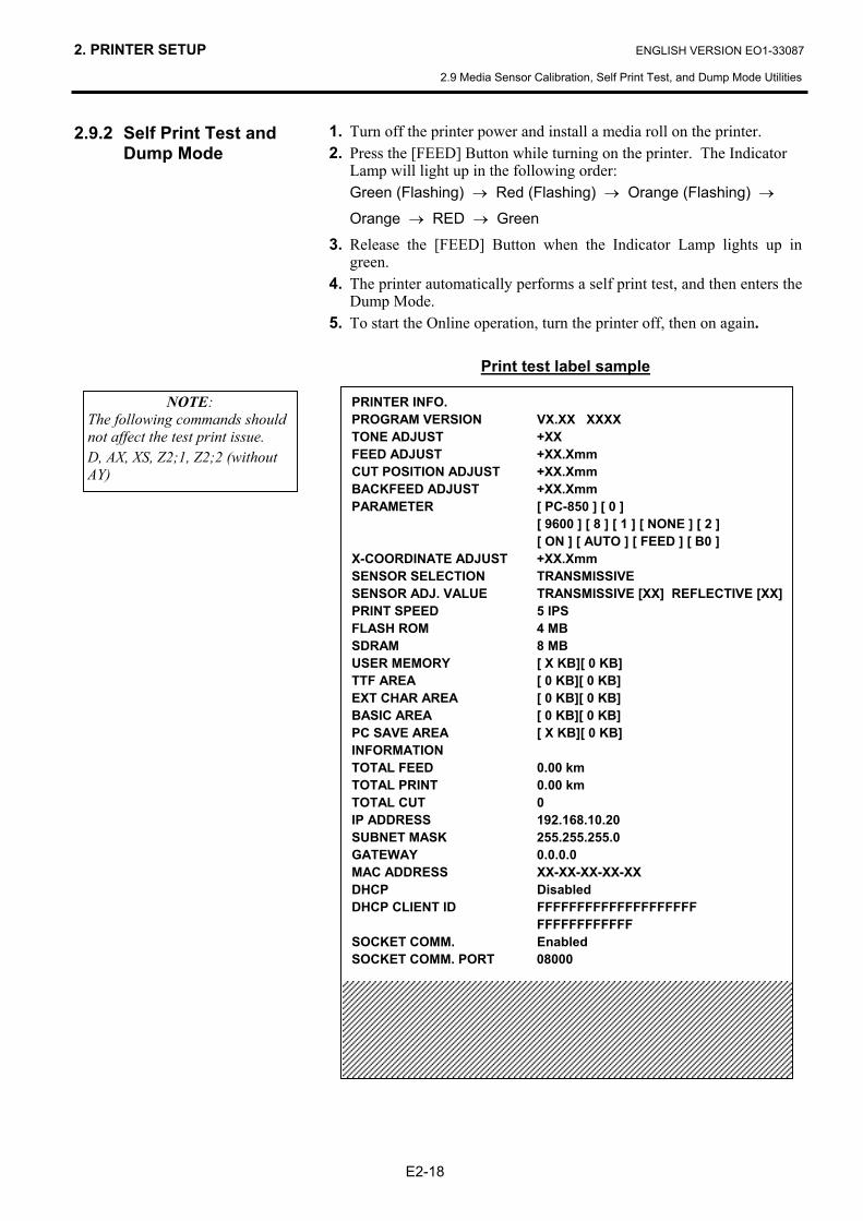
2.9.2 Self Print Test and Dump Mode
1. Turn off the printer power and install a media roll on the printer. 2. Press the [FEED] Button while turning on the printer. The Indicator
Lamp will light up in the following order: Green (Flashing) → Red (Flashing) → Orange (Flashing) →
Orange → RED → Green
3. Release the [FEED] Button when the Indicator Lamp lights up in green.
4. The printer automatically performs a self print test, and then enters the Dump Mode.
5. To start the Online operation, turn the printer off, then on again.
Print test label sample
NOTE: The following commands should not affect the test print issue. D, AX, XS, Z2;1, Z2;2 (without AY)
PRINTER INFO. PROGRAM VERSION VX.XX XXXX TONE ADJUST +XX FEED ADJUST +XX.Xmm CUT POSITION ADJUST +XX.Xmm BACKFEED ADJUST +XX.Xmm PARAMETER [ PC-850 ] [ 0 ]
[ 9600 ] [ 8 ] [ 1 ] [ NONE ] [ 2 ] [ ON ] [ AUTO ] [ FEED ] [ B0 ]
X-COORDINATE ADJUST +XX.Xmm SENSOR SELECTION TRANSMISSIVE SENSOR ADJ. VALUE TRANSMISSIVE [XX] REFLECTIVE [XX]PRINT SPEED 5 IPS FLASH ROM 4 MB SDRAM 8 MB USER MEMORY [ X KB][ 0 KB] TTF AREA [ 0 KB][ 0 KB] EXT CHAR AREA [ 0 KB][ 0 KB] BASIC AREA [ 0 KB][ 0 KB] PC SAVE AREA [ X KB][ 0 KB] INFORMATION TOTAL FEED 0.00 km TOTAL PRINT 0.00 km TOTAL CUT 0 IP ADDRESS 192.168.10.20 SUBNET MASK 255.255.255.0 GATEWAY 0.0.0.0 MAC ADDRESS XX-XX-XX-XX-XX DHCP Disabled DHCP CLIENT ID FFFFFFFFFFFFFFFFFFFF FFFFFFFFFFFF SOCKET COMM. Enabled SOCKET COMM. PORT 08000
2. PRINTER SETUP ENGLISH VERSION EO1-33087
2.9 Media Sensor Calibration, Self Print Test, and Dump Mode Utilities
E2-19
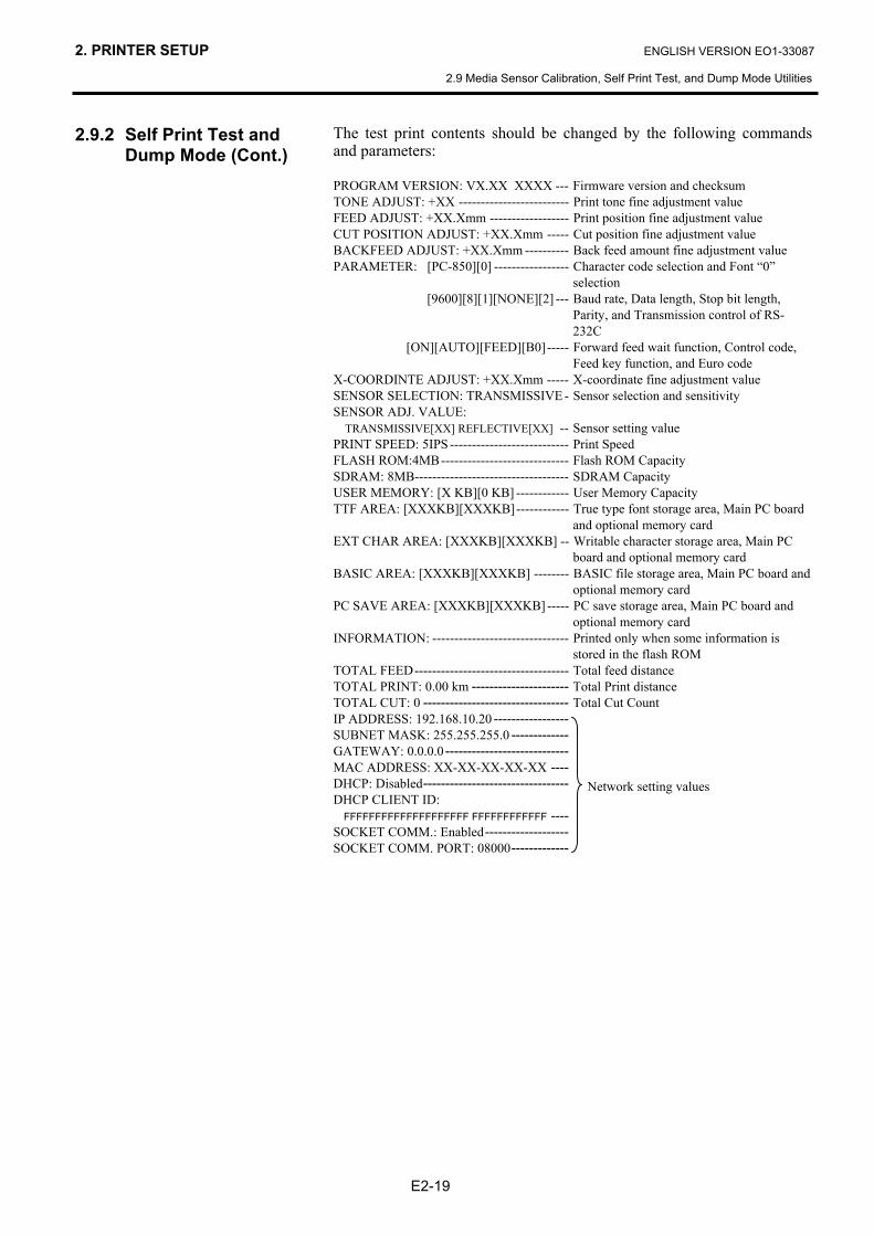
2.9.2 Self Print Test and Dump Mode (Cont.)
The test print contents should be changed by the following commands and parameters: PROGRAM VERSION: VX.XX XXXX --- Firmware version and checksum TONE ADJUST: +XX ------------------------- Print tone fine adjustment value FEED ADJUST: +XX.Xmm ------------------ Print position fine adjustment value CUT POSITION ADJUST: +XX.Xmm ----- Cut position fine adjustment value BACKFEED ADJUST: +XX.Xmm ---------- Back feed amount fine adjustment value PARAMETER: [PC-850][0] ----------------- Character code selection and Font “0”
selection [9600][8][1][NONE][2] --- Baud rate, Data length, Stop bit length,
Parity, and Transmission control of RS-232C
[ON][AUTO][FEED][B0]----- Forward feed wait function, Control code, Feed key function, and Euro code
X-COORDINTE ADJUST: +XX.Xmm ----- X-coordinate fine adjustment value SENSOR SELECTION: TRANSMISSIVE - Sensor selection and sensitivity SENSOR ADJ. VALUE:
TRANSMISSIVE[XX] REFLECTIVE[XX] -- Sensor setting value PRINT SPEED: 5IPS --------------------------- Print Speed FLASH ROM:4MB----------------------------- Flash ROM Capacity SDRAM: 8MB----------------------------------- SDRAM Capacity USER MEMORY: [X KB][0 KB] ------------ User Memory Capacity TTF AREA: [XXXKB][XXXKB]------------ True type font storage area, Main PC board
and optional memory card EXT CHAR AREA: [XXXKB][XXXKB] -- Writable character storage area, Main PC
board and optional memory card BASIC AREA: [XXXKB][XXXKB] -------- BASIC file storage area, Main PC board and
optional memory card PC SAVE AREA: [XXXKB][XXXKB] ----- PC save storage area, Main PC board and
optional memory card INFORMATION: ------------------------------- Printed only when some information is
stored in the flash ROM TOTAL FEED----------------------------------- Total feed distance TOTAL PRINT: 0.00 km ---------------------- Total Print distance TOTAL CUT: 0 --------------------------------- Total Cut Count IP ADDRESS: 192.168.10.20 ----------------- SUBNET MASK: 255.255.255.0 ------------- GATEWAY: 0.0.0.0 ---------------------------- MAC ADDRESS: XX-XX-XX-XX-XX ---- DHCP: Disabled--------------------------------- DHCP CLIENT ID:
FFFFFFFFFFFFFFFFFFFF FFFFFFFFFFFF ---- SOCKET COMM.: Enabled------------------- SOCKET COMM. PORT: 08000-------------
Network setting values
2. PRINTER SETUP ENGLISH VERSION EO1-33087
2.10 How to Use an SD Card
E2-20
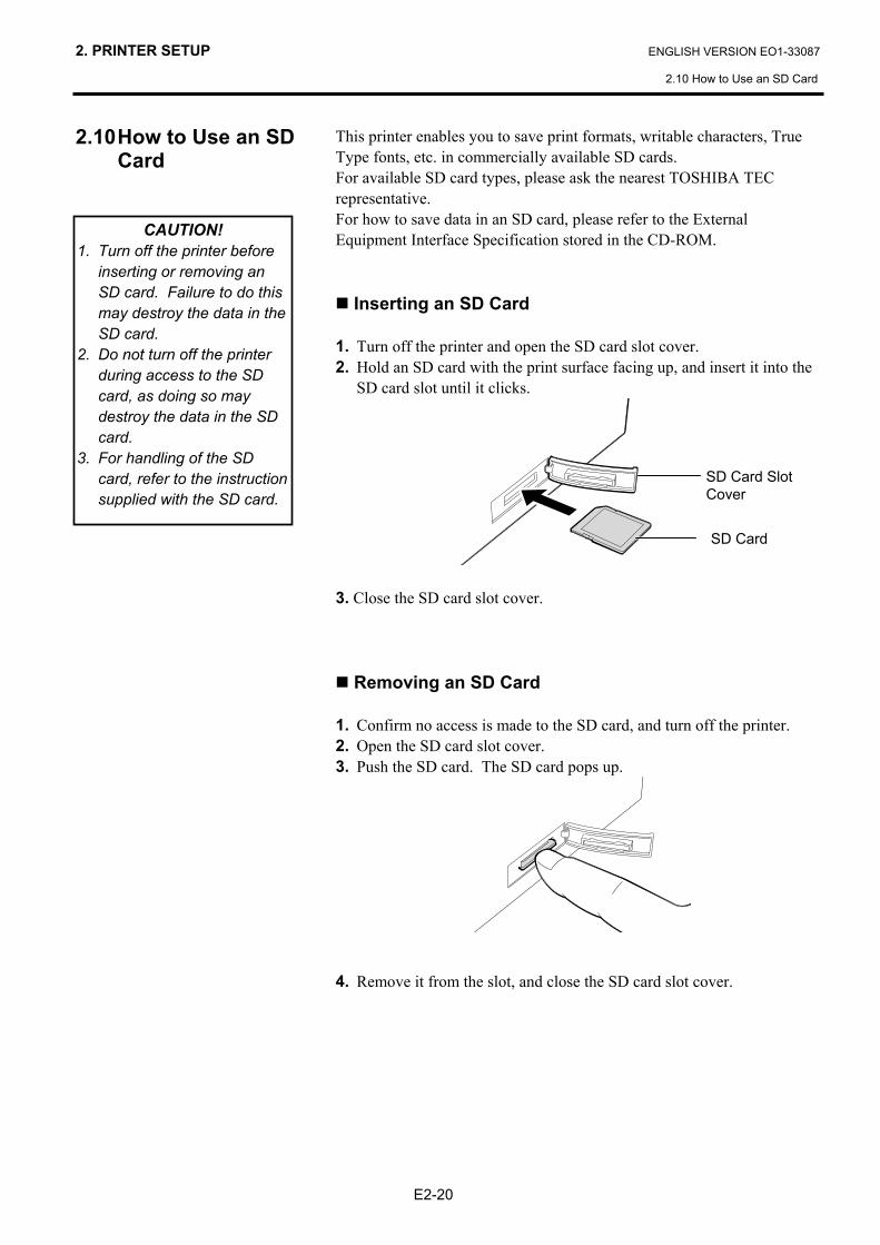
2.10 How to Use an SD Card
This printer enables you to save print formats, writable characters, True Type fonts, etc. in commercially available SD cards. For available SD card types, please ask the nearest TOSHIBA TEC representative. For how to save data in an SD card, please refer to the External Equipment Interface Specification stored in the CD-ROM.
Inserting an SD Card 1. Turn off the printer and open the SD card slot cover. 2. Hold an SD card with the print surface facing up, and insert it into the
SD card slot until it clicks.
3. Close the SD card slot cover.
Removing an SD Card 1. Confirm no access is made to the SD card, and turn off the printer. 2. Open the SD card slot cover. 3. Push the SD card. The SD card pops up.
4. Remove it from the slot, and close the SD card slot cover.
CAUTION! 1. Turn off the printer before
inserting or removing an SD card. Failure to do this may destroy the data in the SD card.
2. Do not turn off the printer during access to the SD card, as doing so may destroy the data in the SD card.
3. For handling of the SD card, refer to the instruction supplied with the SD card.
SD Card Slot Cover
SD Card
3. MAINTENANCE ENGLISH VERSION EO1-33087
3.1 Cleaning
E3- 1
3. MAINTENANCE 3.1 Cleaning 3.1.1 Print Head
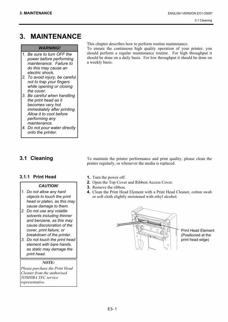
This chapter describes how to perform routine maintenance. To ensure the continuous high quality operation of your printer, you should perform a regular maintenance routine. For high throughput it should be done on a daily basis. For low throughput it should be done on a weekly basis. To maintain the printer performance and print quality, please clean the printer regularly, or whenever the media is replaced. 1. Turn the power off. 2. Open the Top Cover and Ribbon Access Cover. 3. Remove the ribbon. 4. Clean the Print Head Element with a Print Head Cleaner, cotton swab
or soft cloth slightly moistened with ethyl alcohol.
WARNING! 1. Be sure to turn OFF the
power before performing maintenance. Failure to do this may cause an electric shock.
2. To avoid injury, be careful not to trap your fingers while opening or closing the cover.
3. Be careful when handling the print head as it becomes very hot immediately after printing. Allow it to cool before performing any maintenance.
4. Do not pour water directly onto the printer.
CAUTION! 1. Do not allow any hard
objects to touch the print head or platen, as this may cause damage to them.
2. Do not use any volatile solvents including thinner and benzene, as this may cause discoloration of the cover, print failure, or breakdown of the printer.
3. Do not touch the print head element with bare hands, as static may damage the print head.
Print Head Element (Positioned at the print head edge)
NOTE: Please purchase the Print Head Cleaner from the authorised TOSHIBA TEC service representative.
3. MAINTENANCE ENGLISH VERSION EO1-33087
3.1 Cleaning
E3- 2
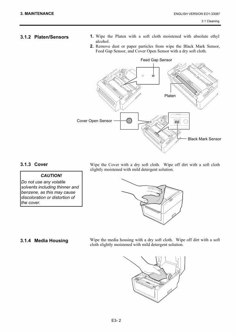
3.1.2 Platen/Sensors 3.1.3 Cover
3.1.4 Media Housing
1. Wipe the Platen with a soft cloth moistened with absolute ethyl alcohol.
2. Remove dust or paper particles from wipe the Black Mark Sensor, Feed Gap Sensor, and Cover Open Sensor with a dry soft cloth.
Wipe the Cover with a dry soft cloth. Wipe off dirt with a soft cloth slightly moistened with mild detergent solution.
Wipe the media housing with a dry soft cloth. Wipe off dirt with a soft cloth slightly moistened with mild detergent solution.
CAUTION! Do not use any volatile solvents including thinner and benzene, as this may cause discoloration or distortion of the cover.
Black Mark Sensor
Platen
Feed Gap Sensor
Cover Open Sensor
3. MAINTENANCE ENGLISH VERSION EO1-33087
3.2 Care/Handling of the Media and Ribbon
E3- 3
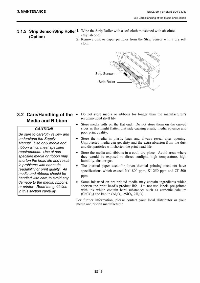
3.1.5 Strip Sensor/Strip Roller (Option)
3.2 Care/Handling of the
Media and Ribbon
1. Wipe the Strip Roller with a soft cloth moistened with absolute ethyl alcohol. 2. Remove dust or paper particles from the Strip Sensor with a dry soft
cloth.
• Do not store media or ribbons for longer than the manufacturer’s recommended shelf life
• Store media rolls on the flat end. Do not store them on the curved sides as this might flatten that side causing erratic media advance and poor print quality.
• Store the media in plastic bags and always reseal after opening. Unprotected media can get dirty and the extra abrasion from the dust and dirt particles will shorten the print head life.
• Store the media and ribbons in a cool, dry place. Avoid areas where they would be exposed to direct sunlight, high temperature, high humidity, dust or gas.
• The thermal paper used for direct thermal printing must not have specifications which exceed Na+ 800 ppm, K+ 250 ppm and Cl- 500 ppm.
• Some ink used on pre-printed media may contain ingredients which shorten the print head’s product life. Do not use labels pre-printed with ink which contain hard substances such as carbonic calcium (CaCO3) and kaolin (Al2O3, 2SiO2, 2H2O).
For further information, please contact your local distributor or your media and ribbon manufacturer.
Strip Sensor
Strip Roller
CAUTION! Be sure to carefully review and understand the Supply Manual. Use only media and ribbon which meet specified requirements. Use of non-specified media or ribbon may shorten the head life and result in problems with bar code readability or print quality. All media and ribbons should be handled with care to avoid any damage to the media, ribbons, or printer. Read the guideline in this section carefully.
4. TROUBLESHOOTING ENGLISH VERSION EO1-33087
4.1 Troubleshooting Guide
E4- 1
4. TROUBLESHOOTING
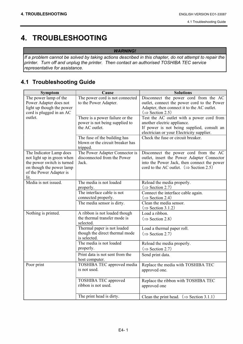
4.1 Troubleshooting Guide
Symptom Cause Solutions The power cord is not connected to the Power Adapter.
Disconnect the power cord from the AC outlet, connect the power cord to the Power Adapter, then connect it to the AC outlet. (⇒ Section 2.5)
There is a power failure or the power is not being supplied to the AC outlet.
Test the AC outlet with a power cord from another electric appliance. If power is not being supplied, consult an electrician or your Electricity supplier.
The power lamp of the Power Adapter does not light up though the power cord is plugged in an AC outlet.
The fuse of the building has blown or the circuit breaker has tripped.
Check the fuse or circuit breaker.
The Indicator Lamp does not light up in green when the power switch is turned on though the power lamp of the Power Adapter is lit.
The Power Adapter Connector is disconnected from the Power Jack.
Disconnect the power cord from the AC outlet, insert the Power Adapter Connector into the Power Jack, then connect the power cord to the AC outlet. (⇒ Section 2.5)
The media is not loaded properly.
Reload the media properly. (⇒ Section 2.7)
The interface cable is not connected properly.
Connect the interface cable again. (⇒ Section 2.4)
Media is not issued.
The media sensor is dirty. Clean the media sensor. (⇒ Section 3.1.2)
A ribbon is not loaded though the thermal transfer mode is selected.
Load a ribbon. (⇒ Section 2.8)
Thermal paper is not loaded though the direct thermal mode is selected.
Load a thermal paper roll. (⇒ Section 2.7)
The media is not loaded properly.
Reload the media properly. (⇒ Section 2.7)
Nothing is printed.
Print data is not sent from the host computer.
Send print data.
TOSHIBA TEC approved media is not used.
Replace the media with TOSHIBA TEC approved one.
TOSHIBA TEC approved ribbon is not used.
Replace the ribbon with TOSHIBA TEC approved one
Poor print
The print head is dirty. Clean the print head. (⇒ Section 3.1.1)
WARNING! If a problem cannot be solved by taking actions described in this chapter, do not attempt to repair the printer. Turn off and unplug the printer. Then contact an authorised TOSHIBA TEC service representative for assistance.
4. TROUBLESHOOTING ENGLISH VERSION EO1-33087
4.2 Status Lamp
E4- 2
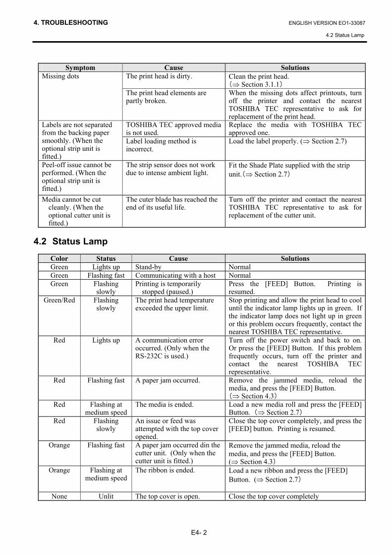
Symptom Cause Solutions
The print head is dirty. Clean the print head. (⇒ Section 3.1.1)
Missing dots
The print head elements are partly broken.
When the missing dots affect printouts, turn off the printer and contact the nearest TOSHIBA TEC representative to ask for replacement of the print head.
TOSHIBA TEC approved media is not used.
Replace the media with TOSHIBA TEC approved one.
Labels are not separated from the backing paper smoothly. (When the optional strip unit is fitted.)
Label loading method is incorrect.
Load the label properly. (⇒ Section 2.7)
Peel-off issue cannot be performed. (When the optional strip unit is fitted.)
The strip sensor does not work due to intense ambient light.
Fit the Shade Plate supplied with the strip unit.(⇒ Section 2.7)
Media cannot be cut cleanly. (When the optional cutter unit is fitted.)
The cuter blade has reached the end of its useful life.
Turn off the printer and contact the nearest TOSHIBA TEC representative to ask for replacement of the cutter unit.
4.2 Status Lamp
Color Status Cause Solutions Green Lights up Stand-by Normal Green Flashing fast Communicating with a host Normal Green Flashing
slowly Printing is temporarily
stopped (paused.) Press the [FEED] Button. Printing is resumed.
Green/Red Flashing slowly
The print head temperature exceeded the upper limit.
Stop printing and allow the print head to cool until the indicator lamp lights up in green. If the indicator lamp does not light up in green or this problem occurs frequently, contact the nearest TOSHIBA TEC representative.
Red Lights up A communication error occurred. (Only when the RS-232C is used.)
Turn off the power switch and back to on. Or press the [FEED] Button. If this problem frequently occurs, turn off the printer and contact the nearest TOSHIBA TEC representative.
Red Flashing fast A paper jam occurred. Remove the jammed media, reload the media, and press the [FEED] Button. (⇒ Section 4.3)
Red Flashing at medium speed
The media is ended. Load a new media roll and press the [FEED] Button. (⇒ Section 2.7)
Red Flashing slowly
An issue or feed was attempted with the top cover opened.
Close the top cover completely, and press the [FEED] button. Printing is resumed.
Orange Flashing fast A paper jam occurred din the cutter unit. (Only when the cutter unit is fitted.)
Remove the jammed media, reload the media, and press the [FEED] Button. (⇒ Section 4.3)
Orange Flashing at medium speed
The ribbon is ended. Load a new ribbon and press the [FEED] Button. (⇒ Section 2.7)
None Unlit The top cover is open. Close the top cover completely
4. TROUBLESHOOTING ENGLISH VERSION EO1-33087
4.3 Removing Jammed Media
E4- 3
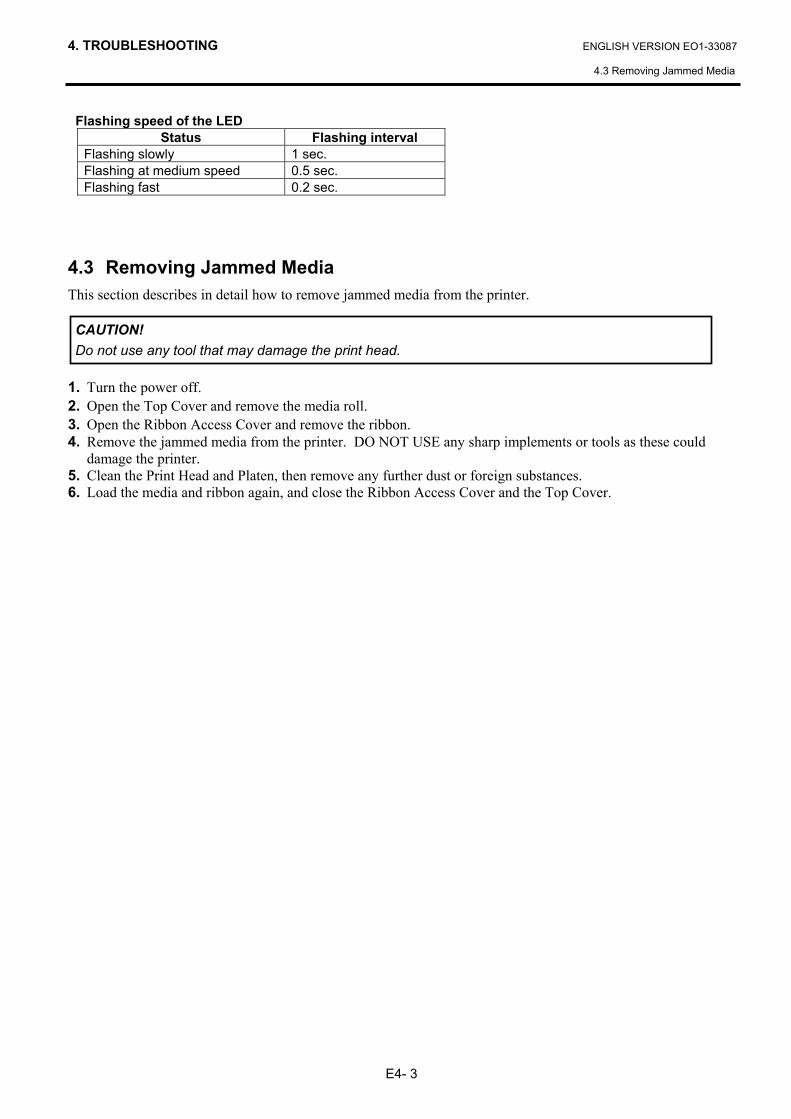
Flashing speed of the LED Status Flashing interval
Flashing slowly 1 sec. Flashing at medium speed 0.5 sec. Flashing fast 0.2 sec.
4.3 Removing Jammed Media This section describes in detail how to remove jammed media from the printer.
1. Turn the power off. 2. Open the Top Cover and remove the media roll. 3. Open the Ribbon Access Cover and remove the ribbon. 4. Remove the jammed media from the printer. DO NOT USE any sharp implements or tools as these could
damage the printer. 5. Clean the Print Head and Platen, then remove any further dust or foreign substances. 6. Load the media and ribbon again, and close the Ribbon Access Cover and the Top Cover.
CAUTION! Do not use any tool that may damage the print head.
APPENDIX 1 SPECIFICATIONS ENGLISH VERSION EO1-33087
A1.1 Printer
EA1- 1
APPENDIX 1 SPECIFICATIONS Appendix 1 describes the printer specifications and supplies for use on the B-EV4T printer.
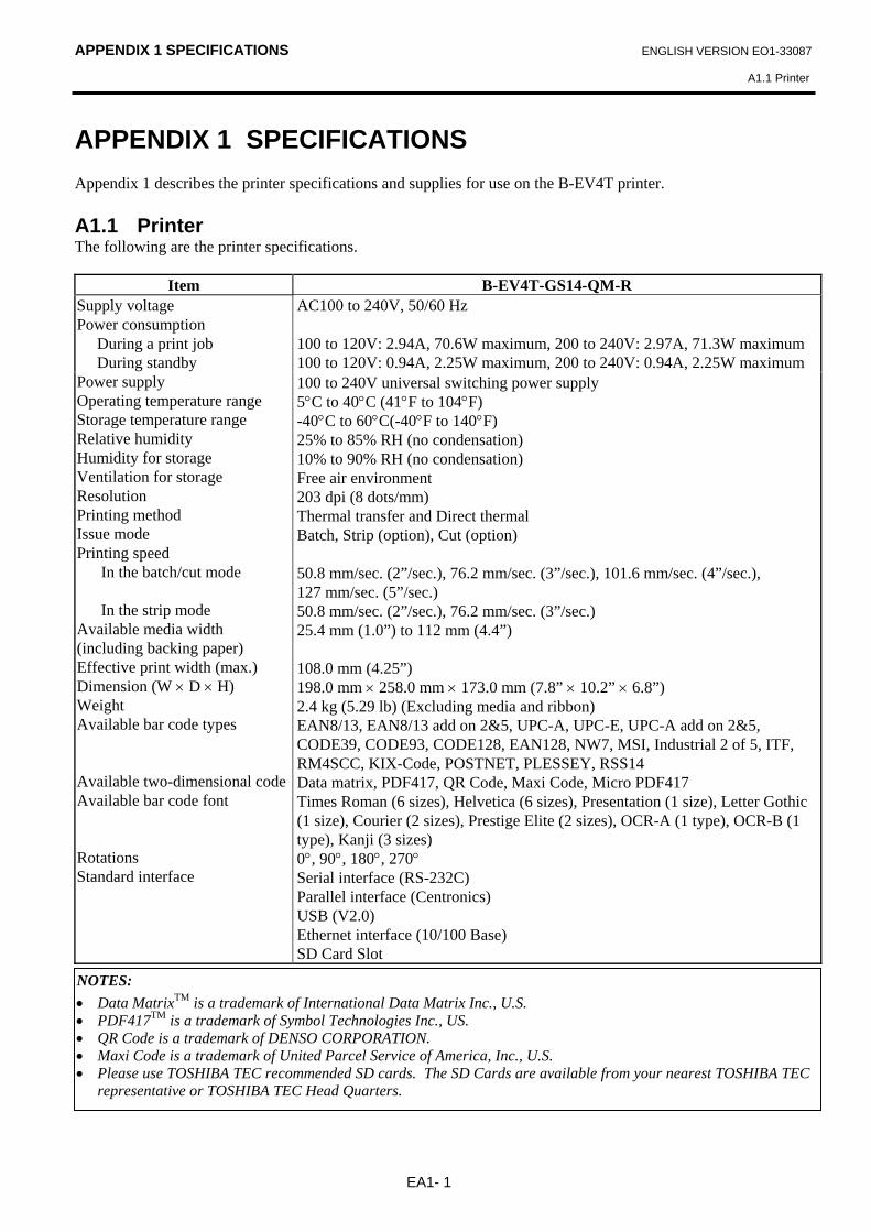
A1.1 Printer The following are the printer specifications.
Item B-EV4T-GS14-QM-R
AC100 to 240V, 50/60 Hz 100 to 120V: 2.94A, 70.6W maximum, 200 to 240V: 2.97A, 71.3W maximum 100 to 120V: 0.94A, 2.25W maximum, 200 to 240V: 0.94A, 2.25W maximum
Supply voltage Power consumption During a print job During standby Power supply Operating temperature range Storage temperature range Relative humidity Humidity for storage Ventilation for storage Resolution Printing method Issue mode Printing speed In the batch/cut mode In the strip mode Available media width (including backing paper) Effective print width (max.) Dimension (W × D × H) Weight Available bar code types Available two-dimensional code Available bar code font Rotations Standard interface
100 to 240V universal switching power supply 5°C to 40°C (41°F to 104°F) -40°C to 60°C(-40°F to 140°F) 25% to 85% RH (no condensation) 10% to 90% RH (no condensation) Free air environment 203 dpi (8 dots/mm) Thermal transfer and Direct thermal Batch, Strip (option), Cut (option) 50.8 mm/sec. (2”/sec.), 76.2 mm/sec. (3”/sec.), 101.6 mm/sec. (4”/sec.), 127 mm/sec. (5”/sec.) 50.8 mm/sec. (2”/sec.), 76.2 mm/sec. (3”/sec.) 25.4 mm (1.0”) to 112 mm (4.4”) 108.0 mm (4.25”) 198.0 mm × 258.0 mm × 173.0 mm (7.8” × 10.2” × 6.8”) 2.4 kg (5.29 lb) (Excluding media and ribbon) EAN8/13, EAN8/13 add on 2&5, UPC-A, UPC-E, UPC-A add on 2&5, CODE39, CODE93, CODE128, EAN128, NW7, MSI, Industrial 2 of 5, ITF, RM4SCC, KIX-Code, POSTNET, PLESSEY, RSS14 Data matrix, PDF417, QR Code, Maxi Code, Micro PDF417 Times Roman (6 sizes), Helvetica (6 sizes), Presentation (1 size), Letter Gothic (1 size), Courier (2 sizes), Prestige Elite (2 sizes), OCR-A (1 type), OCR-B (1 type), Kanji (3 sizes) 0°, 90°, 180°, 270° Serial interface (RS-232C) Parallel interface (Centronics) USB (V2.0) Ethernet interface (10/100 Base) SD Card Slot
NOTES: • Data MatrixTM is a trademark of International Data Matrix Inc., U.S. • PDF417TM is a trademark of Symbol Technologies Inc., US. • QR Code is a trademark of DENSO CORPORATION. • Maxi Code is a trademark of United Parcel Service of America, Inc., U.S. • Please use TOSHIBA TEC recommended SD cards. The SD Cards are available from your nearest TOSHIBA TEC
representative or TOSHIBA TEC Head Quarters.
APPENDIX 1 SPECIFICATIONS ENGLISH VERSION EO1-33087
A1.2 Options
EA1- 2
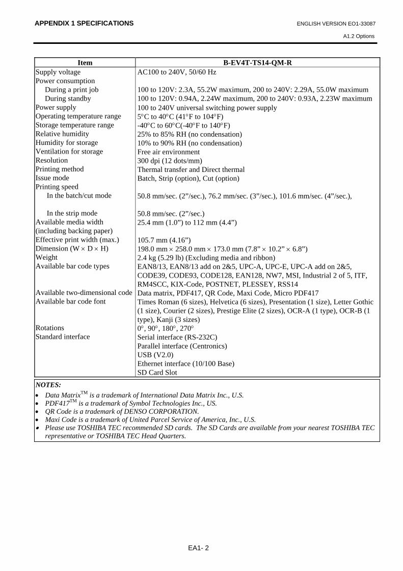
Item B-EV4T-TS14-QM-R AC100 to 240V, 50/60 Hz 100 to 120V: 2.3A, 55.2W maximum, 200 to 240V: 2.29A, 55.0W maximum 100 to 120V: 0.94A, 2.24W maximum, 200 to 240V: 0.93A, 2.23W maximum
Supply voltage Power consumption During a print job During standby Power supply Operating temperature range Storage temperature range Relative humidity Humidity for storage Ventilation for storage Resolution Printing method Issue mode Printing speed In the batch/cut mode In the strip mode Available media width (including backing paper) Effective print width (max.) Dimension (W × D × H) Weight Available bar code types Available two-dimensional code Available bar code font Rotations Standard interface
100 to 240V universal switching power supply 5°C to 40°C (41°F to 104°F) -40°C to 60°C(-40°F to 140°F) 25% to 85% RH (no condensation) 10% to 90% RH (no condensation) Free air environment 300 dpi (12 dots/mm) Thermal transfer and Direct thermal Batch, Strip (option), Cut (option) 50.8 mm/sec. (2”/sec.), 76.2 mm/sec. (3”/sec.), 101.6 mm/sec. (4”/sec.), 50.8 mm/sec. (2”/sec.) 25.4 mm (1.0”) to 112 mm (4.4”) 105.7 mm (4.16”) 198.0 mm × 258.0 mm × 173.0 mm (7.8” × 10.2” × 6.8”) 2.4 kg (5.29 lb) (Excluding media and ribbon) EAN8/13, EAN8/13 add on 2&5, UPC-A, UPC-E, UPC-A add on 2&5, CODE39, CODE93, CODE128, EAN128, NW7, MSI, Industrial 2 of 5, ITF, RM4SCC, KIX-Code, POSTNET, PLESSEY, RSS14 Data matrix, PDF417, QR Code, Maxi Code, Micro PDF417 Times Roman (6 sizes), Helvetica (6 sizes), Presentation (1 size), Letter Gothic (1 size), Courier (2 sizes), Prestige Elite (2 sizes), OCR-A (1 type), OCR-B (1 type), Kanji (3 sizes) 0°, 90°, 180°, 270° Serial interface (RS-232C) Parallel interface (Centronics) USB (V2.0) Ethernet interface (10/100 Base) SD Card Slot
NOTES: • Data MatrixTM is a trademark of International Data Matrix Inc., U.S. • PDF417TM is a trademark of Symbol Technologies Inc., US. • QR Code is a trademark of DENSO CORPORATION. • Maxi Code is a trademark of United Parcel Service of America, Inc., U.S. • Please use TOSHIBA TEC recommended SD cards. The SD Cards are available from your nearest TOSHIBA TEC
representative or TOSHIBA TEC Head Quarters.
APPENDIX 1 SPECIFICATIONS ENGLISH VERSION EO1-33087
A1.2 Options
EA1- 3
A1.2 Options
Option Name Type Description AC Adapter Cover B-EV904-AC-QM-R Attached to the printer bottom for housing the AC
adapter. Cutter module B-EV204-F-QM-R
B-EV204-P-QM-R A cutter unit that makes full cuts. A cutter unit that makes partial cuts.
Strip module B-EV904-H-QM-R When attached to the front of the Media Outlet, this module allows the on-demand strip issue by detecting the presence or lack of a label.
External media roll hanger B-EV904-PH-QM-R When this option is attached to the printer, a media roll with an outer roll diameter up to 203mm (8”) and inner core diameter of 76.2mm (3”) can be used.
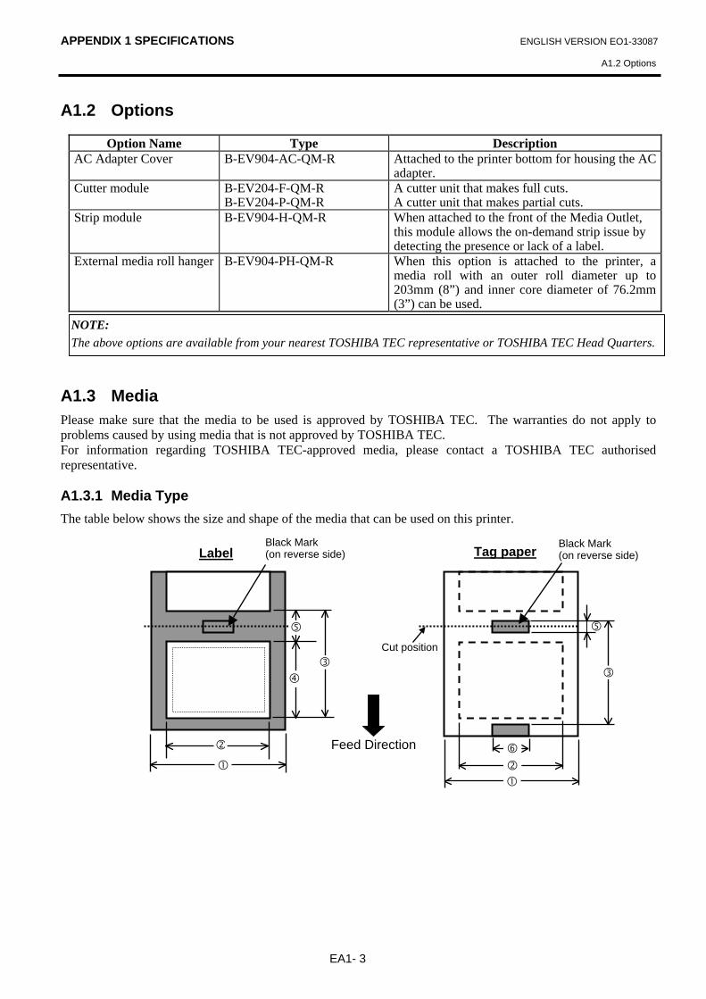
A1.3 Media Please make sure that the media to be used is approved by TOSHIBA TEC. The warranties do not apply to problems caused by using media that is not approved by TOSHIBA TEC. For information regarding TOSHIBA TEC-approved media, please contact a TOSHIBA TEC authorised representative. A1.3.1 Media Type
The table below shows the size and shape of the media that can be used on this printer.
NOTE: The above options are available from your nearest TOSHIBA TEC representative or TOSHIBA TEC Head Quarters.
Feed Direction
Black Mark (on reverse side) Tag paper
Cut position
Black Mark (on reverse side)
Label
APPENDIX 1 SPECIFICATIONS ENGLISH VERSION EO1-33087
A1.3 Media
EA1- 4
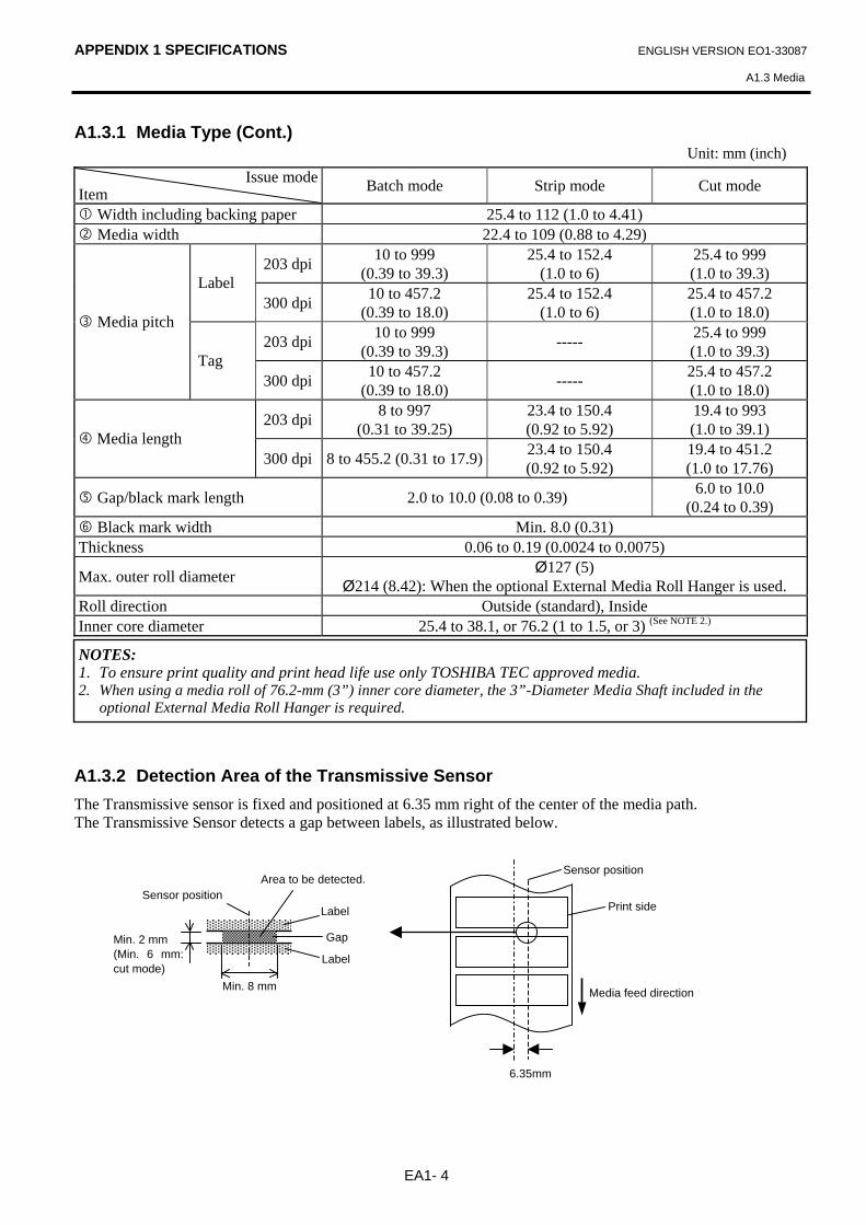
A1.3.1 Media Type (Cont.) Unit: mm (inch)
Issue mode Item Batch mode Strip mode Cut mode
Width including backing paper 25.4 to 112 (1.0 to 4.41) Media width 22.4 to 109 (0.88 to 4.29)
203 dpi 10 to 999 (0.39 to 39.3)
25.4 to 152.4 (1.0 to 6)
25.4 to 999 (1.0 to 39.3) Label
300 dpi 10 to 457.2 (0.39 to 18.0)
25.4 to 152.4 (1.0 to 6)
25.4 to 457.2 (1.0 to 18.0)
203 dpi 10 to 999 (0.39 to 39.3) ----- 25.4 to 999
(1.0 to 39.3)
Media pitch
Tag 300 dpi 10 to 457.2
(0.39 to 18.0) ----- 25.4 to 457.2 (1.0 to 18.0)
203 dpi 8 to 997 (0.31 to 39.25)
23.4 to 150.4 (0.92 to 5.92)
19.4 to 993 (1.0 to 39.1) Media length
300 dpi 8 to 455.2 (0.31 to 17.9) 23.4 to 150.4 (0.92 to 5.92)
19.4 to 451.2 (1.0 to 17.76)
Gap/black mark length 2.0 to 10.0 (0.08 to 0.39) 6.0 to 10.0 (0.24 to 0.39)
Black mark width Min. 8.0 (0.31) Thickness 0.06 to 0.19 (0.0024 to 0.0075)
Max. outer roll diameter Ø127 (5) Ø214 (8.42): When the optional External Media Roll Hanger is used.
Roll direction Outside (standard), Inside Inner core diameter 25.4 to 38.1, or 76.2 (1 to 1.5, or 3) (See NOTE 2.)
A1.3.2 Detection Area of the Transmissive Sensor The Transmissive sensor is fixed and positioned at 6.35 mm right of the center of the media path. The Transmissive Sensor detects a gap between labels, as illustrated below.
NOTES: 1. To ensure print quality and print head life use only TOSHIBA TEC approved media. 2. When using a media roll of 76.2-mm (3”) inner core diameter, the 3”-Diameter Media Shaft included in the
optional External Media Roll Hanger is required.
Min. 2 mm (Min. 6 mm: cut mode)
Min. 8 mm
Sensor position Area to be detected.
Label
Gap
Label
Sensor position
Media feed direction
Print side
6.35mm
APPENDIX 1 SPECIFICATIONS ENGLISH VERSION EO1-33087
A1.3 Media
EA1- 5
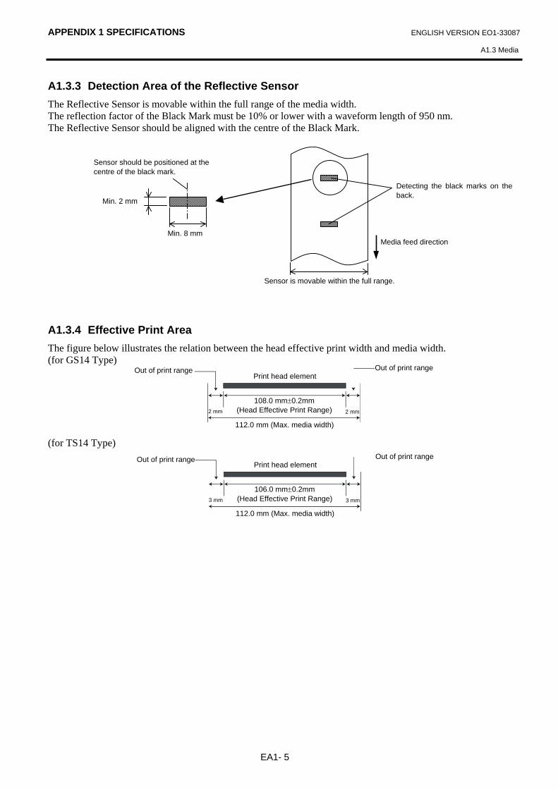
A1.3.3 Detection Area of the Reflective Sensor The Reflective Sensor is movable within the full range of the media width. The reflection factor of the Black Mark must be 10% or lower with a waveform length of 950 nm. The Reflective Sensor should be aligned with the centre of the Black Mark. A1.3.4 Effective Print Area The figure below illustrates the relation between the head effective print width and media width. (for GS14 Type) (for TS14 Type)
Min. 2 mm
Min. 8 mm
Sensor should be positioned at the centre of the black mark.
Media feed direction
Detecting the black marks on the back.
Sensor is movable within the full range.
2 mm
112.0 mm (Max. media width)
108.0 mm±0.2mm (Head Effective Print Range)
Out of print range Out of print range
2 mm
Print head element
3 mm
112.0 mm (Max. media width)
106.0 mm±0.2mm (Head Effective Print Range)
Out of print range Out of print range
3 mm
Print head element
APPENDIX 1 SPECIFICATIONS ENGLISH VERSION EO1-33087
A1.4 Ribbon
EA1- 6
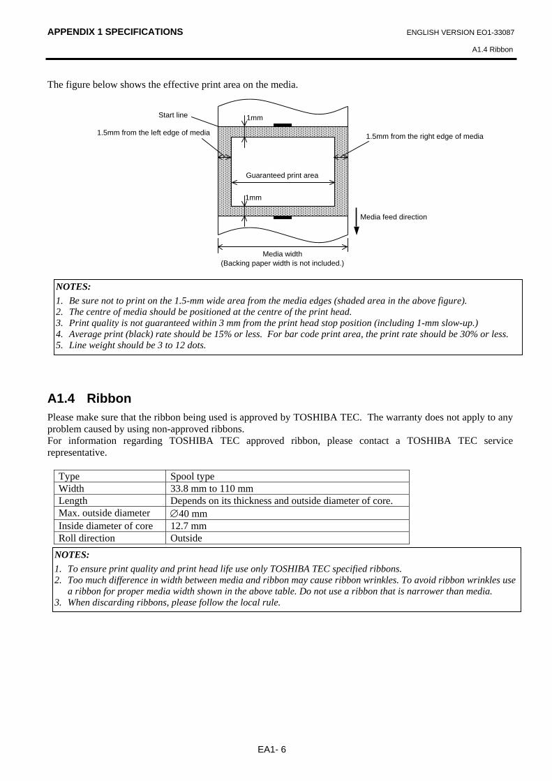
The figure below shows the effective print area on the media.
A1.4 Ribbon Please make sure that the ribbon being used is approved by TOSHIBA TEC. The warranty does not apply to any problem caused by using non-approved ribbons. For information regarding TOSHIBA TEC approved ribbon, please contact a TOSHIBA TEC service representative.
Type Spool type Width 33.8 mm to 110 mm Length Depends on its thickness and outside diameter of core. Max. outside diameter ∅40 mm Inside diameter of core 12.7 mm Roll direction Outside
NOTES: 1. Be sure not to print on the 1.5-mm wide area from the media edges (shaded area in the above figure). 2. The centre of media should be positioned at the centre of the print head. 3. Print quality is not guaranteed within 3 mm from the print head stop position (including 1-mm slow-up.) 4. Average print (black) rate should be 15% or less. For bar code print area, the print rate should be 30% or less. 5. Line weight should be 3 to 12 dots.
Guaranteed print area
1mm
1mm
1.5mm from the right edge of media1.5mm from the left edge of media
Media feed direction
Media width (Backing paper width is not included.)
Start line
NOTES: 1. To ensure print quality and print head life use only TOSHIBA TEC specified ribbons. 2. Too much difference in width between media and ribbon may cause ribbon wrinkles. To avoid ribbon wrinkles use
a ribbon for proper media width shown in the above table. Do not use a ribbon that is narrower than media. 3. When discarding ribbons, please follow the local rule.
APPENDIX 2 INTERFACE ENGLISH VERSION EO1-33087
APPENDIX 2 INTERFACE
EA2- 1
APPENDIX 2 INTERFACE Interface Cables
To prevent radiation and reception of electrical noise, the interface cables must meet the following requirements: • Fully shielded and fitted with metal or metallized connector housings. • Keep as short as possible. • Should not be bundled tightly with power cords. • Should not be tied to power line conduits.
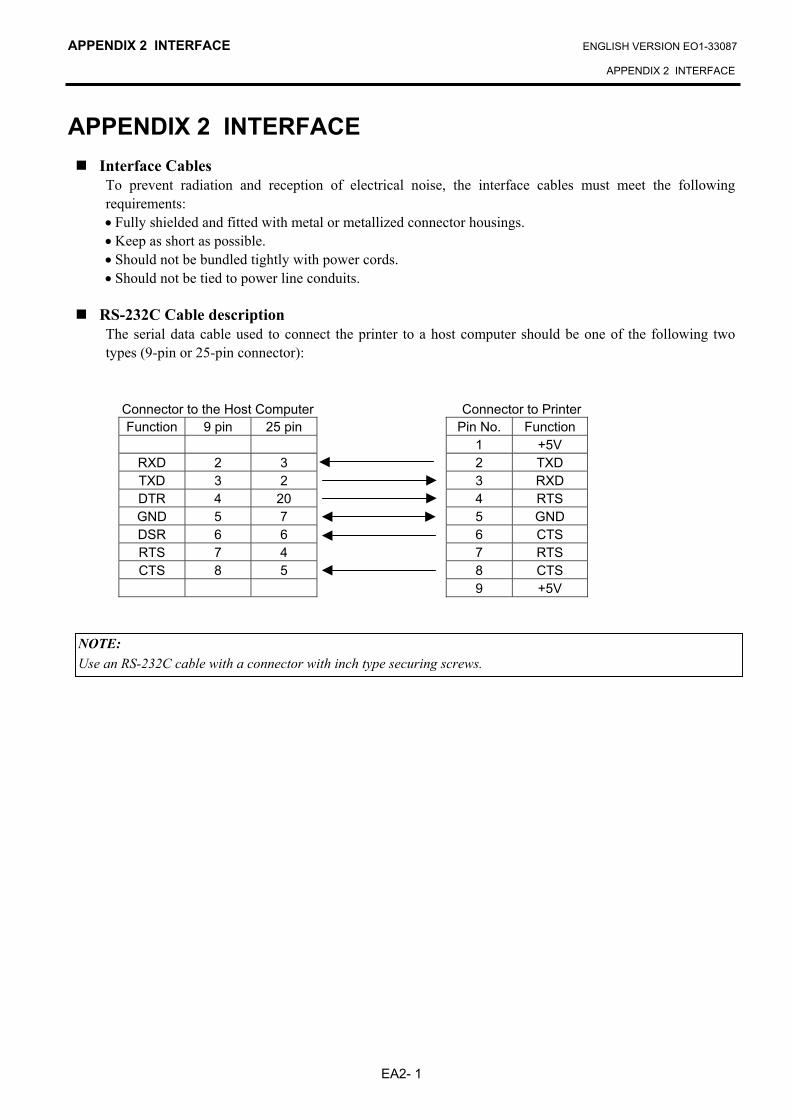
RS-232C Cable description
The serial data cable used to connect the printer to a host computer should be one of the following two types (9-pin or 25-pin connector):
NOTE: Use an RS-232C cable with a connector with inch type securing screws.
Connector to the Host Computer Function 9 pin 25 pin
RXD 2 3 TXD 3 2 DTR 4 20 GND 5 7 DSR 6 6 RTS 7 4 CTS 8 5
Connector to Printer Pin No. Function
1 +5V 2 TXD 3 RXD 4 RTS 5 GND 6 CTS 7 RTS 8 CTS 9 +5V
GLOSSARIES ENGLISH VERSION EO1-33087
GLOSSARIES
GLOSSARIES Bar code A code which represents alphanumeric characters by using a series of black and white stripes in different widths. Bar codes are used in various industrial fields: Manufacturing, Hospitals, Libraries, Retail, Transportation, Warehousing, etc. Reading bar codes is a fast and accurate means of capturing data while keyboard entry tends to be slow and inaccurate. Batch mode Issue mode that continuously prints media until the required number has been printed. Black mark A mark printed on the media enabling the printer to detect the correct start position of the media, helping to maintain constant print position. Black mark sensor A reflective sensor that detects the difference between a black mark and the print area to find the print start position. Cut mode Printer mode of operation where an (optional) cutter module is installed to automatically cut media from the supply roll after they are printed. The print command can specify to cut every media or to cut after a set number of media have been printed. Direct thermal printing A printing method using no ribbon, but thermal media which reacts to heat. The thermal print head heats the thermal media directly, causing print image to be printed on the media. DPI Dots Per Inch A unit used to express print density or resolution. Feed gap sensor A transmissive sensor that detects the difference between the gap between labels and the label itself, to find the print start position of the label. Font A complete set of alphanumeric characters in one style of type. E.g. Helvetica, Courier, Times
Gap Distance from the bottom of one label to the top of the next label. IPS Inch per second A unit used to express print speed. Label A type of media with adhesive backing supplied on a backing paper. Media Material on which images are printed by the printer. Label, tag paper, fanfold paper, perforated paper, etc. Printer driver A software program that will convert the application program’s printing request into the language that the printer understands. Print head element The thermal print head consists of a single line of tiny resistive elements which when current is allowed to flow through them it heats up causing a small dot to be burned onto thermal paper or a small dot of ink to be transferred from a thermal ribbon to ordinary paper. Printing speed The speed at which printing occurs. This speed is expressed in units of IPS (inches per second). Resolution The degree of detail to which an image can be duplicated. The minimum unit of divided image is called a pixel. As the resolution becomes higher, the number of pixels increases, resulting in a more detailed image. Ribbon An inked film used to transfer an image onto the media. In the thermal transfer printing, it is heated by the thermal print head, causing an image to be transferred onto the media. Strip mode One of the printer modes of operation where an optional strip module is installed to separate printed labels from the backing paper one by one.
GLOSSARIES ENGLISH VERSION EO1-33087
GLOSSARIES
Supply Media and ribbon Tag A type of media having no adhesive backing but black marks to indicate the print area. Usually tags are made of cardboard or other durable material. Thermal print head A print head using thermal transfer or thermal direct printing method. Thermal transfer printing A printing method that the thermal print head heats an ink or resin coating on the ribbon against the media, causing the ink/resin to transfer onto the media.


E EO1-33087


![Barcode & Card Solution 젂문기업 과장 차홍기 010.4806카드케이스& 목걸이 2-6. 분야별카드샘플 [ 싞분증/ 자격증카드] [ 뷰티멤버쉽카드] [ 프렌차이즈식당멤버쉽카드](https://img.pdfslide.fr/doc/110x75/6092efe181ef7209b75f2f0d/barcode-card-solution-ee-e-e-010-eoe.jpg)