Embed Size (px)
Citation preview
FMGM 2015 – PM Dight (ed.) © 2015 Australian Centre for Geomechanics, Perth, ISBN 978-0-9924810-2-5
FMGM 2015, Sydney, Australia 397
Use of monitoring data during construction to refine cavern design
B Shen Pells Sullivan Meynink, Australia
TR Nash Pells Sullivan Meynink, Australia
R Bertuzzi Pells Sullivan Meynink, Australia
SJ Clarke Pells Sullivan Meynink, Australia
Abstract
This paper describes how monitoring data was used during construction to refine the design of a large span cavern built in Ashfield Shale in Sydney. The cavern is part of a rail tunnel project comprising 15.5 km of twin tunnels. The cavern is 160 m in length, with a height of up to 17 m; it spans 23 m, with a cover of between 14 and 17 m. Instrumentation used during construction comprised surface settlement survey, in-tunnel convergence using both survey and tape extensometers, borehole inclinometers, ShapeAccelArray (SAA) inclinometers, multipoint rod extensometers, wire extensometers, endoscopes and vibrating wire piezometers (VWP).
Based on the observed ground conditions and monitoring during construction, it was possible to revise rock mass and in situ stress parameters to refine the design. Design changes included increases in advance distances, revised pile lengths and spacing, optimisation of the mesh reinforced arch and a revised excavation profile. These changes resulted in a significant reduction in construction time and a more economical overall project outcome.
1 Introduction
Sydney’s North West Rail Link (NWRL) includes 15.5 km twin tunnels from Bella Vista to Epping, five new cut and cover stations, several enlarged openings at the tunnel-station interfaces and a rail crossover cavern at Castle Hill. The running tunnels are excavated by tunnel boring machine (TBM). Roadheaders excavate the tunnels where they connect to existing rail lines at Epping as well as the crossover cavern.
The joint venture of Thiess John Holland Dragados (TJHD) was awarded the contract by Transport for New South Wales (TfNSW) to construct the tunnels and cavern, and excavate the stations boxes. TJHD awarded the design to Hyder, CH2MHill and Pells Sullivan Meynink (PSM). PSM was responsible for the design of the temporary support for the mined (non-TBM) tunnels and crossover cavern, and was retained to provide construction phase geotechnical services (CPS) for the project.
This paper presents the monitoring employed during construction of the Castle Hill crossover cavern and how monitoring data together with geological mapping was utilised during construction to refine the design and achieve significant time and cost savings.
2 Geological setting
The Castle Hill crossover cavern is within the Ashfield Shale which is the basal unit of the Wianamatta Group. It comprises dark grey to black sideritic claystone and siltstone grading into a distinct laminite of fine sandstone and siltstone. Three of the four sub units of the Ashfield Shale defined by Herbert & Helby (1980) are observed, as described below.
The Regentville Siltstone overlies the Kellyville Laminite which together forms the upper parts of the cavern and cover rock. The Rouse Hill Siltstone occurs at the base of the cavern. The bottom 1 to 2 m of the cavern
doi:10.36487/ACG_rep/1508_26_Shen
Use of monitoring data during construction to refine cavern design B Shen et al.
398 FMGM 2015, Sydney, Australia
comprises interbedded sandstone and siltstone of the Mittagong Formation. The Hawkesbury Sandstone underlies the Mittagong Formation and occurs 2 to 3 m below the cavern invert.
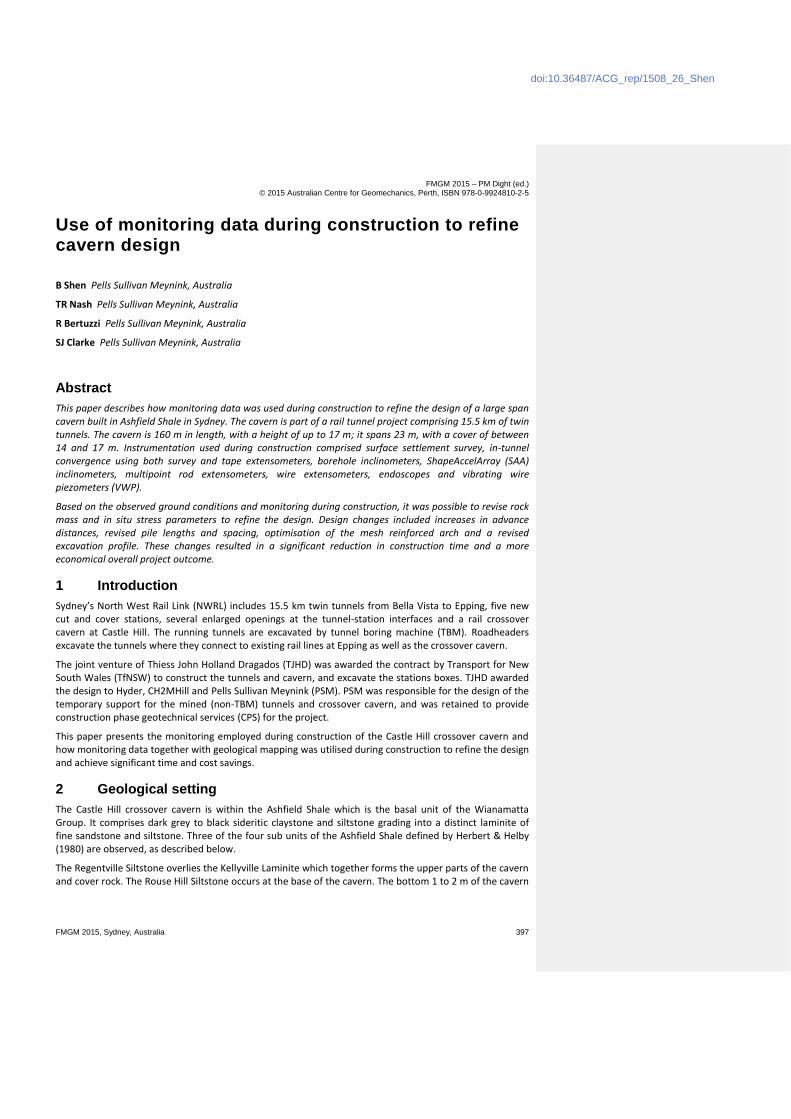
Thirty two cored boreholes were drilled across the site. The section profile shown in Figure 1 is typical of conditions encountered and comprises:
Shale-derived residual soil to 2 m thick, overlying.
Ashfield Shale — extremely weathered to moderately weathered Regentville Siltstone 6 to 10 m depth comprising Class III to Class V shale (Pells et al. 1998), overlying.
Ashfield Shale — slightly weathered to fresh Regentville Siltstone, Kellyville Laminite and Rouse Hill Siltstone to 25 to 35 m depth comprising Class I to II shale, overlying.
Mittagong Formation — slightly weathered to fresh 32 to 40 m depth Class I and II sandstone.
Figure 1 Ground condition approximately 32 m inbye from the portal
At the crossover cavern, the Ashfield Shale has a medium to high intact rock strength with bedding dips generally less than 5° and multiple joint sets moderately dipping, predominantly towards the northwest and southeast. The Mittagong Formation is typically of high intact rock strength with relatively widely spaced defects.
Groundwater levels prior to excavation were between 14 and 22 m above the cavern invert.
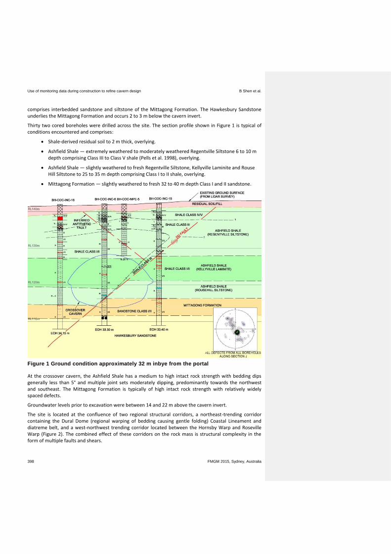
The site is located at the confluence of two regional structural corridors, a northeast-trending corridor containing the Dural Dome (regional warping of bedding causing gentle folding) Coastal Lineament and diatreme belt, and a west-northwest trending corridor located between the Hornsby Warp and Roseville Warp (Figure 2). The combined effect of these corridors on the rock mass is structural complexity in the form of multiple faults and shears.
Civil tunnelling
FMGM 2015, Sydney, Australia 399
Figure 2 Large structure model
A three dimensional structural model was developed at the cavern based on borehole data, particularly borehole imaging from 29 of the 32 boreholes, and large-scale geological structural interpretation. From this, two distinct faulting regimes are inferred:
Compressional — characterised by bedding parallel shear zones up to approximately 150 mm in thickness, and moderate angle (40 to 50°) faults 100 to 150 mm thick constrained between bedding shears.
Extensional — characterised by variably-sized zones (single planes to 200 to 300 mm) of gouge material in moderate to steeply dipping (40 to 75°) fault zones.
Two faults significant to the design intersect the cavern, a fault termed the DD Fault and a series of antithetic faults (Figure 1).
2.1 DD Fault
The DD Fault was identified in and correlated between eighteen boreholes across the site, seventeen of which included borehole imaging data. The fault dips between 45 and 55° to the northwest, which is close to the alignment of the regional Dural Dome structure, and has a normal dip-slip movement causing a maximum of approximately 2 m stratigraphic offset in the west to 0.5 m in the east of the cavern (Figure 1).
Based on the above borehole data and mapping of the Castle Hill station box and crossover cavern, the fault is characterised by a 2 m wide zone of fractured rock comprising crushed seams 100 to 200 m wide to a single discrete plane. There is increased fracturing adjacent to the fault comprising planar to curved joints dipping sub-parallel to the fault, which are rough and clean and spaced between 200 to 300 mm. There are occasional shears orthogonal to the main fault.
Use of monitoring data during construction to refine cavern design B Shen et al.
400 FMGM 2015, Sydney, Australia
2.2 Antithetic faulting
A series of normal faults dipping between 40 and 55° to the southeast occur across the site and are intersected by the cavern. These faults were intersected by boreholes and modelled based on borehole imagery data. These faults dip at right angles to the direction of the DD Fault and are therefore termed antithetic faults.
The faults have a normal dip-slip movement causing a maximum of approximately 1.5 m stratigraphic offset. They are planar to undulating, with clay and rock fragment infill between 10 and 40 mm thick.
In addition to these main faults, individual subordinate fault planes and fault zones sub parallel to the DD Fault were identified based on borehole data and mapping throughout the cavern.
3 Cavern design
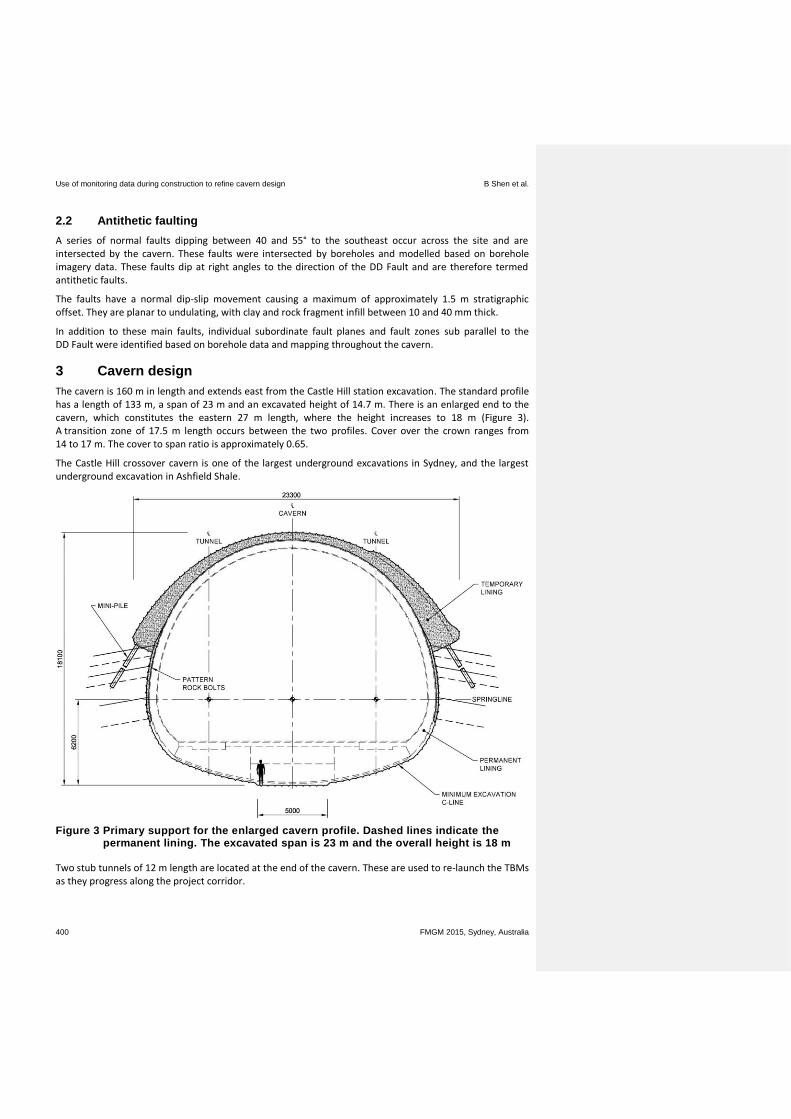
The cavern is 160 m in length and extends east from the Castle Hill station excavation. The standard profile has a length of 133 m, a span of 23 m and an excavated height of 14.7 m. There is an enlarged end to the cavern, which constitutes the eastern 27 m length, where the height increases to 18 m (Figure 3). A transition zone of 17.5 m length occurs between the two profiles. Cover over the crown ranges from 14 to 17 m. The cover to span ratio is approximately 0.65.
The Castle Hill crossover cavern is one of the largest underground excavations in Sydney, and the largest underground excavation in Ashfield Shale.
Figure 3 Primary support for the enlarged cavern profile. Dashed lines indicate the permanent lining. The excavated span is 23 m and the overall height is 18 m
Two stub tunnels of 12 m length are located at the end of the cavern. These are used to re-launch the TBMs as they progress along the project corridor.
Civil tunnelling
FMGM 2015, Sydney, Australia 401
The centre of the cavern passes beneath McMullen Avenue, a significant five lane road operated by the NSW Roads and Maritime Services (RMS). Single and multi-storey buildings overlie the eastern end of the cavern (Figure 5).
The design considered the poorest ground conditions, which were associated with high design loads and also poor rock bolt geotechnical capacity. A sprayed concrete (shotcrete) structural lining was adopted as the temporary support, rather than bolted support as is more common in Sydney tunnels.
Owing to the significant height of the cavern, a heading and bench sequence was adopted. Two headings were driven as a risk mitigation measure, with the initial heading used as an exploratory adit to confirm ground conditions before opening up the full span.
The second (full span) heading follows the first, though was set back at least 30 m from the initial heading. This distance allows the encountered ground conditions to be properly assessed, the piles on the south-eastern side to be installed and provides reliable monitoring data to ensure the adequacy of the support installed in the initial and full span headings.
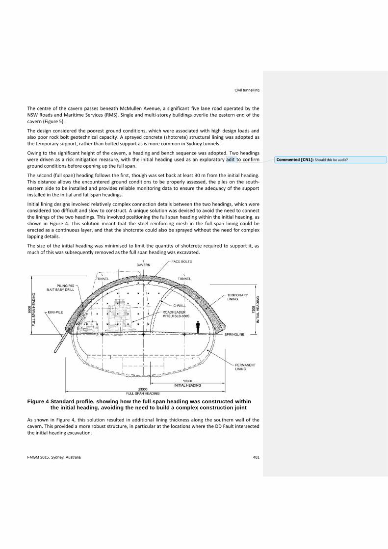
Initial lining designs involved relatively complex connection details between the two headings, which were considered too difficult and slow to construct. A unique solution was devised to avoid the need to connect the linings of the two headings. This involved positioning the full span heading within the initial heading, as shown in Figure 4. This solution meant that the steel reinforcing mesh in the full span lining could be erected as a continuous layer, and that the shotcrete could also be sprayed without the need for complex lapping details.
The size of the initial heading was minimised to limit the quantity of shotcrete required to support it, as much of this was subsequently removed as the full span heading was excavated.
Figure 4 Standard profile, showing how the full span heading was constructed within the initial heading, avoiding the need to build a complex construction joint
As shown in Figure 4, this solution resulted in additional lining thickness along the southern wall of the cavern. This provided a more robust structure, in particular at the locations where the DD Fault intersected the initial heading excavation.
Commented [CN1]: Should this be audit?
Use of monitoring data during construction to refine cavern design B Shen et al.
402 FMGM 2015, Sydney, Australia
Due to the extent of faulting and joints expected in the shale bedrock units, the design required careful consideration of the stability of the rock supporting the base of the shotcrete arch. As shown in Figure 3, for the enlarged profile, the base of the arch is located above a 7 m high overhanging rock face. Small diameter piles were used to transfer load from the arch into the rock at a lower level and further away from the excavation to ensure stability of the arch. Pattern rock bolts were also employed to support the rock face.
Due to the more favourable side wall geometry of the Standard cavern profile, piles were only required if unexpectedly poor conditions were found, though this condition did not eventuate. Pattern rock bolts were employed to provide the necessary support.
The bench was excavated in stages, with the initial stages of low height to allow rock bolting to occur.
Multiple analysis methods and software programs were used to design the temporary support. These include two and three-dimensional finite element analyses that capture the overall behaviour of the excavation and support interaction. The stability of particular aspects of the design, such as the rock face beneath the base of the arch, was assessed using other techniques such as structural analysis, limit equilibrium methods and hand calculations.
Three versions of the same support design were developed to account for variations in the ground conditions. The differences related to shotcrete thickness, reinforcement quantities, and strength gain requirements.
Initial design predictions of surface movement ranged from 20 up to 40 mm, with the larger movements being associated with shear displacement along the DD Fault.
4 Instrumentation and monitoring plan
As part of the design, an instrumentation and monitoring (I&M) plan was developed for the project by PSM for which the CPS team installed and read various geotechnical instruments. This included processing, interpreting and review of monitoring data obtained.
The objectives of the I&M plan was to monitor the performance of the works during construction and to validate design assumptions by comparing actual displacements against those predicted. The I&M plan also allowed existing infrastructure to be monitored to ensure structures were not adversely affected by the works. Instrumentation was of significant importance at the crossover cavern to manage the risk of excavating a large span cavern in very challenging ground conditions. The intensity of monitoring employed at the cavern reflects the high risk nature of this part of the project.
Monitoring at the crossover cavern comprised the following:
Surface settlement arrays (survey)
In-tunnel convergence and crown sag arrays (survey and tape extensometer)
Borehole inclinometers
ShapeAccelArray (SAA) inclinometers
Multi-point rod extensometers
Wire extensometers
Endoscope inspections
VWPs
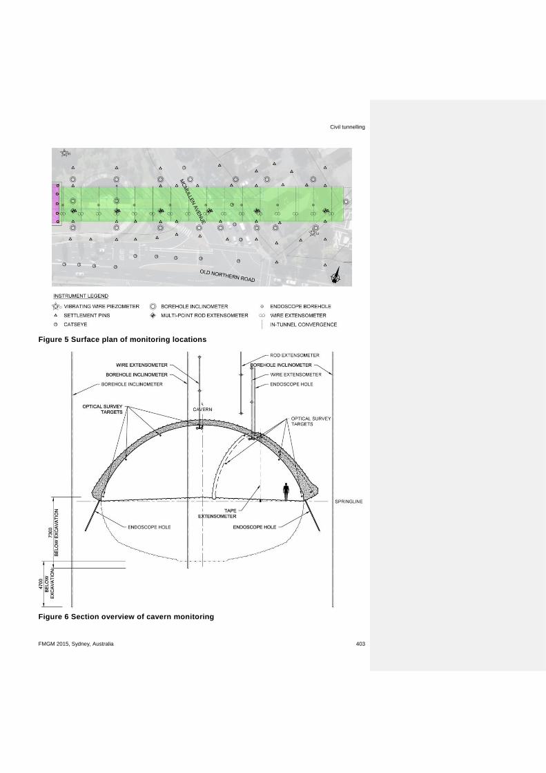
Figures 5 and 6 provide an overview of the instrumentation adopted for the crossover cavern. The following sections provide details and the rationale behind each component of the monitoring.
Civil tunnelling
FMGM 2015, Sydney, Australia 403
Figure 5 Surface plan of monitoring locations
Figure 6 Section overview of cavern monitoring
Use of monitoring data during construction to refine cavern design B Shen et al.
404 FMGM 2015, Sydney, Australia
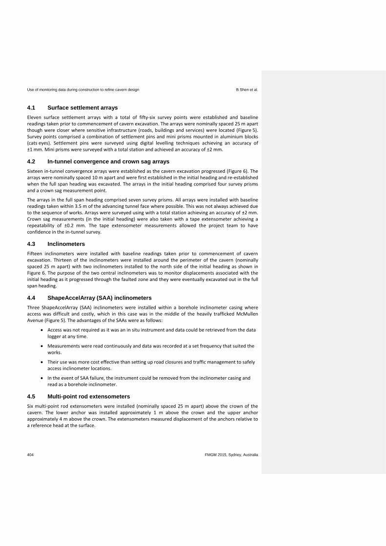
4.1 Surface settlement arrays
Eleven surface settlement arrays with a total of fifty-six survey points were established and baseline readings taken prior to commencement of cavern excavation. The arrays were nominally spaced 25 m apart though were closer where sensitive infrastructure (roads, buildings and services) were located (Figure 5). Survey points comprised a combination of settlement pins and mini prisms mounted in aluminium blocks (cats eyes). Settlement pins were surveyed using digital levelling techniques achieving an accuracy of ±1 mm. Mini prisms were surveyed with a total station and achieved an accuracy of ±2 mm.
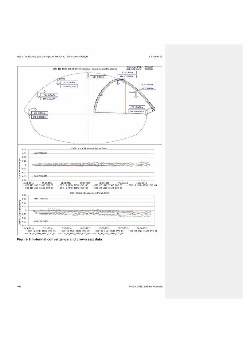
4.2 In-tunnel convergence and crown sag arrays
Sixteen in-tunnel convergence arrays were established as the cavern excavation progressed (Figure 6). The arrays were nominally spaced 10 m apart and were first established in the initial heading and re-established when the full span heading was excavated. The arrays in the initial heading comprised four survey prisms and a crown sag measurement point.
The arrays in the full span heading comprised seven survey prisms. All arrays were installed with baseline readings taken within 3.5 m of the advancing tunnel face where possible. This was not always achieved due to the sequence of works. Arrays were surveyed using with a total station achieving an accuracy of ±2 mm. Crown sag measurements (in the initial heading) were also taken with a tape extensometer achieving a repeatability of ±0.2 mm. The tape extensometer measurements allowed the project team to have confidence in the in-tunnel survey.
4.3 Inclinometers
Fifteen inclinometers were installed with baseline readings taken prior to commencement of cavern excavation. Thirteen of the inclinometers were installed around the perimeter of the cavern (nominally spaced 25 m apart) with two inclinometers installed to the north side of the initial heading as shown in Figure 6. The purpose of the two central inclinometers was to monitor displacements associated with the initial heading as it progressed through the faulted zone and they were eventually excavated out in the full span heading.
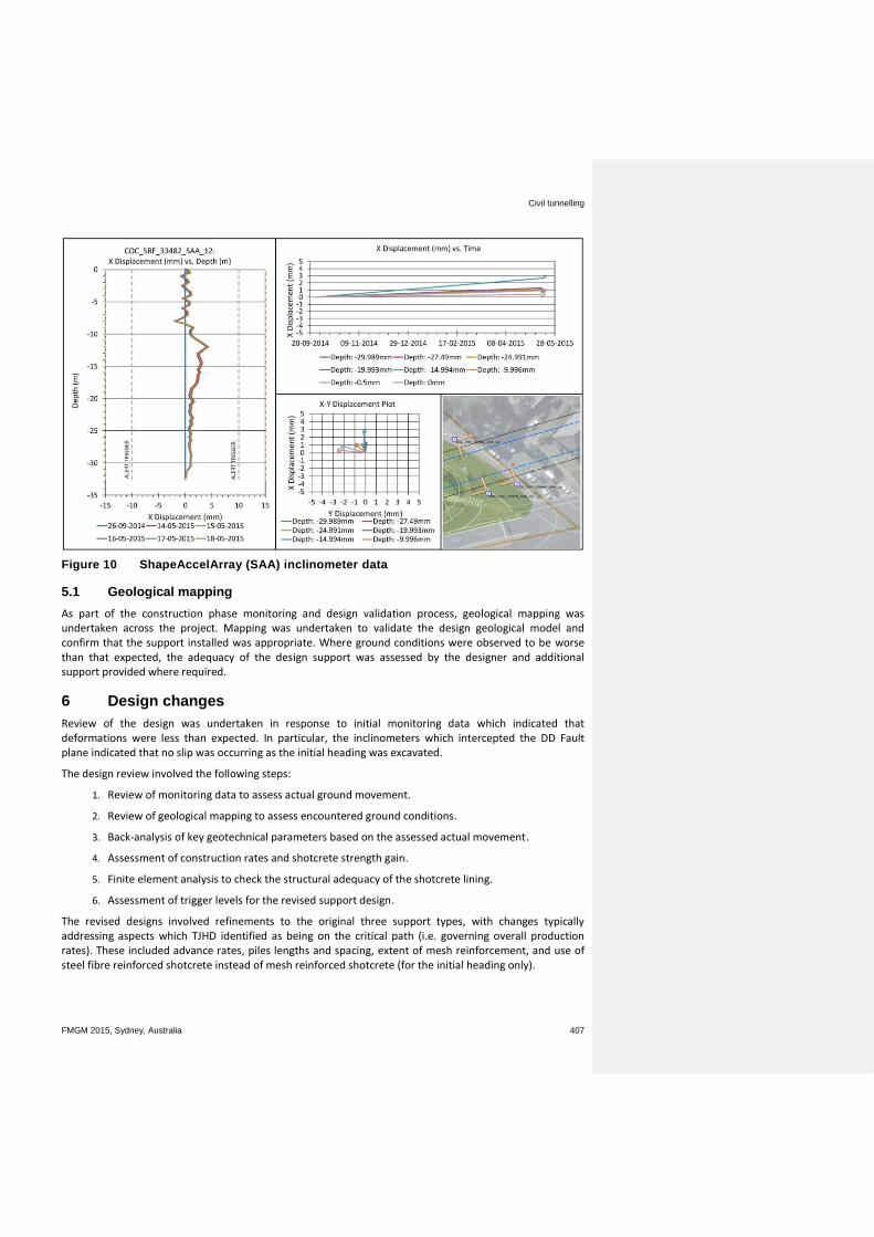
4.4 ShapeAccelArray (SAA) inclinometers
Three ShapeAccelArray (SAA) inclinometers were installed within a borehole inclinometer casing where access was difficult and costly, which in this case was in the middle of the heavily trafficked McMullen Avenue (Figure 5). The advantages of the SAAs were as follows:
Access was not required as it was an in situ instrument and data could be retrieved from the data logger at any time.
Measurements were read continuously and data was recorded at a set frequency that suited the works.
Their use was more cost effective than setting up road closures and traffic management to safely access inclinometer locations.
In the event of SAA failure, the instrument could be removed from the inclinometer casing and read as a borehole inclinometer.
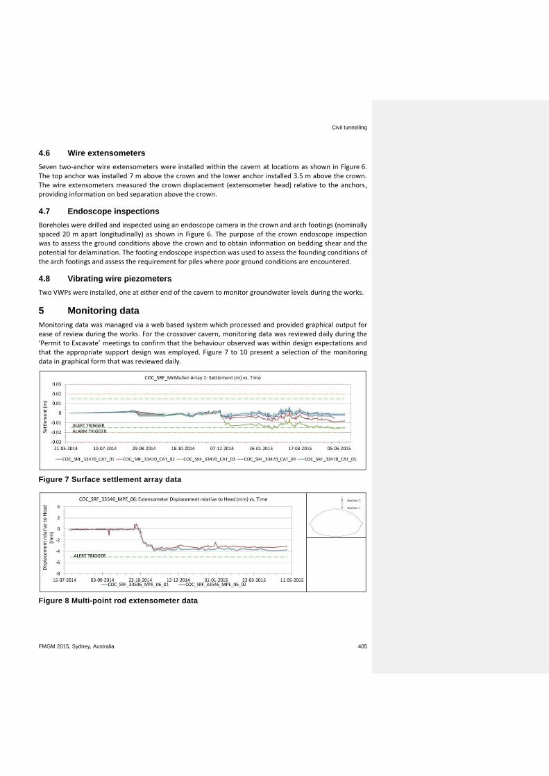
4.5 Multi-point rod extensometers
Six multi-point rod extensometers were installed (nominally spaced 25 m apart) above the crown of the cavern. The lower anchor was installed approximately 1 m above the crown and the upper anchor approximately 4 m above the crown. The extensometers measured displacement of the anchors relative to a reference head at the surface.
Civil tunnelling
FMGM 2015, Sydney, Australia 405
4.6 Wire extensometers
Seven two-anchor wire extensometers were installed within the cavern at locations as shown in Figure 6. The top anchor was installed 7 m above the crown and the lower anchor installed 3.5 m above the crown. The wire extensometers measured the crown displacement (extensometer head) relative to the anchors, providing information on bed separation above the crown.
4.7 Endoscope inspections
Boreholes were drilled and inspected using an endoscope camera in the crown and arch footings (nominally spaced 20 m apart longitudinally) as shown in Figure 6. The purpose of the crown endoscope inspection was to assess the ground conditions above the crown and to obtain information on bedding shear and the potential for delamination. The footing endoscope inspection was used to assess the founding conditions of the arch footings and assess the requirement for piles where poor ground conditions are encountered.
4.8 Vibrating wire piezometers
Two VWPs were installed, one at either end of the cavern to monitor groundwater levels during the works.
5 Monitoring data
Monitoring data was managed via a web based system which processed and provided graphical output for ease of review during the works. For the crossover cavern, monitoring data was reviewed daily during the ‘Permit to Excavate’ meetings to confirm that the behaviour observed was within design expectations and that the appropriate support design was employed. Figure 7 to 10 present a selection of the monitoring data in graphical form that was reviewed daily.
Figure 7 Surface settlement array data
Figure 8 Multi-point rod extensometer data
Use of monitoring data during construction to refine cavern design B Shen et al.
406 FMGM 2015, Sydney, Australia
Figure 9 In-tunnel convergence and crown sag data
Civil tunnelling
FMGM 2015, Sydney, Australia 407
Figure 10 ShapeAccelArray (SAA) inclinometer data
5.1 Geological mapping
As part of the construction phase monitoring and design validation process, geological mapping was undertaken across the project. Mapping was undertaken to validate the design geological model and confirm that the support installed was appropriate. Where ground conditions were observed to be worse than that expected, the adequacy of the design support was assessed by the designer and additional support provided where required.
6 Design changes
Review of the design was undertaken in response to initial monitoring data which indicated that deformations were less than expected. In particular, the inclinometers which intercepted the DD Fault plane indicated that no slip was occurring as the initial heading was excavated.
The design review involved the following steps:
1. Review of monitoring data to assess actual ground movement.
2. Review of geological mapping to assess encountered ground conditions.
3. Back-analysis of key geotechnical parameters based on the assessed actual movement.
4. Assessment of construction rates and shotcrete strength gain.
5. Finite element analysis to check the structural adequacy of the shotcrete lining.
6. Assessment of trigger levels for the revised support design.
The revised designs involved refinements to the original three support types, with changes typically addressing aspects which TJHD identified as being on the critical path (i.e. governing overall production rates). These included advance rates, piles lengths and spacing, extent of mesh reinforcement, and use of steel fibre reinforced shotcrete instead of mesh reinforced shotcrete (for the initial heading only).
Use of monitoring data during construction to refine cavern design B Shen et al.
408 FMGM 2015, Sydney, Australia
As the initial monitoring indicated small movements, the back-analysis placed greater reliance on the more precise monitoring instruments (e.g. rod extensometers, tape extensometers, and borehole inclinometers). The in-tunnel convergence and surface settlement survey results were generally within the accuracy of the survey method, such that clear movement trends were not evident.
The displacements predicted in design were based on the fastest face advance rate that could theoretically occur. In practice, the advance achieved was approximately half that rate, which resulted in the shotcrete lining having greater strength and stiffness closer to the advancing face.
A range of numerical analysis were undertaken to back-analyse parameters which resulted in calculated deformations similar to those measured. The deformations were most sensitive to in situ stresses in the shale bedrock units, and defect stiffness and strength parameters (including those of the DD Fault).
This approach was used to refine the support design for the initial heading, the full span heading and the bench designs. The refined design allowed increased face advances, increases to the overall advance rate, the use of fibre-reinforced shotcrete in lieu of mesh-reinforced shotcrete, and an increase in bench excavation depths.
The changes allowed the time required for the excavation and support of the headings to be reduced by about two weeks and that of the bench by a similar amount.
7 Conclusion
The Castle Hill crossover cavern was completed without damage to sensitive surface infrastructure or disruption to traffic on McMullen Avenue. The risk associated with excavating a large span cavern in challenging ground conditions was managed in part by the successful implementation of the instrumentation and monitoring plan.
Instrumentation was used to monitor the performance of the works and refine design during construction. This required quality data to be obtained from a well planned and executed monitoring regime together with detailed geological mapping.
Implementation of monitoring and undertaking detailed mapping to obtain reliable data comes at a cost. However, in this case, the refinement of the design at the crossover cavern allowed a significant reduction in construction time which resulted in a substantial overall economic benefit to the project.
Acknowledgement
The authors thank TJHD and TfNSW for their permission to publish this paper. They also thank the engineers and geologists involved in the project for their dedication and professionalism, which resulted in a highly successful project.
References
Herbert, C & Helby, R 1980, ‘Wianamatta Group and Mittagong Formation’, Department of Mineral Resources, Geological Survey of New South Wales, no. 26, A Guide to the Sydney Basin, Department of Western Government Printer.
Pells, PJN, Mostyn, G & Walker, BF 1998, ‘Foundations on sandstone and shale in the Sydney region’, Australian Geomechanics, vol. 33, no. 3, pp. 17-26.

![Use of molecular biology tools for rapid identification ... · vaccine (VSVRI, Egypt) was isolated from cattle during HS outbreak in Egypt since 1962 and identified as PM Type B [4,5,23,24]](https://img.pdfslide.fr/doc/110x75/5e8b0927bd8172489267fc18/use-of-molecular-biology-tools-for-rapid-identification-vaccine-vsvri-egypt.jpg)