Embed Size (px)
Citation preview
European Organisation for Astronomical Research in the Southern Hemisphere
Organisation Européenne pour des Recherches Astronomiques dans l’Hémisphère Austral
Europäische Organisationfür astronomische Forschung in der
südlichen Hemisphäre
VERY LARGE TELESCOPE
Instrument Control Software Laboratory Exercise
Doc. No.: VLT-MAN-ESO-17240-4618
Issue: 0.23
Date: 04.10.2008
Prepared: M.Kiekebusch J.Knudstrup D.Popovic Name Date Signature Approved: G.Chiozzi Name Date Signature Released: M. Peron Name Date Signature
ESO, Karl-Schwarzschild-Str. 2, 85748 Garching bei München, Germany
Instrument Control Software Laboratory Exercise
Doc: Issue Date Page
VLT-MAN-ESO-17240-4618 0.24 04.10.2008 2 of 79
ESO, Karl-Schwarzschild-Str. 2, 85748 Garching bei München, Germany
CHANGE RECORD
ISSUE DATE SECTION/PARA. AFFECTED
REASON/INITIATION DOCUMENTS/REMARKS
0.23 2008-10-04 All First issue.
Instrument Control Software Laboratory Exercise
Doc: Issue Date Page
VLT-MAN-ESO-17240-4618 0.24 04.10.2008 3 of 79
ESO, Karl-Schwarzschild-Str. 2, 85748 Garching bei München, Germany
TABLE OF CONTENTS 1 Introduction ..................................................................................................................................... 7
1.1 Purpose .................................................................................................................................. 7 1.2 Acknowledgments .................................................................................................................. 7 1.3 Scope ..................................................................................................................................... 7 1.4 List of Abbreviations & Acronyms .......................................................................................... 7 1.5 List of Applicable and Referenced Documents ...................................................................... 8 1.6 Reference Documents ........................................................................................................... 8 1.7 Guidelines for Reading this Document .................................................................................. 9
2 Overview ....................................................................................................................................... 10 2.1 The Instrument ..................................................................................................................... 10 2.2 Hardware Architecture ......................................................................................................... 10
2.2.1 Devices ........................................................................................................................ 10 2.2.2 Computers and Hardware ........................................................................................... 10
2.3 Software Architecture ........................................................................................................... 12 2.4 Environment Configuration ................................................................................................... 13
2.4.1 User Accounts/Environments ...................................................................................... 13 2.4.2 CCS/LCC Environments .............................................................................................. 14
3 Exercise #1: Getting Started ......................................................................................................... 15 3.1 Purpose ................................................................................................................................ 15 3.2 Implementation Details ......................................................................................................... 15 3.3 Exercise Steps ..................................................................................................................... 15
3.3.1 Preparing the XXXX Modules for the Basic Adaptation .............................................. 15 3.3.1.1 Checking and Adapting the Environment .............................................................. 15 3.3.1.2 Retrieve the XXXX Base Module ........................................................................... 15 3.3.1.3 Initial Adaptation of the Integration Module ........................................................... 16 3.3.1.4 Retrieving the XXXX Modules ............................................................................... 16
3.3.2 Adapting the Template Instrument to the Exercise Instrument ................................... 16 3.3.2.1 Create the Exercise Instrument Software .............................................................. 16 3.3.2.2 Adapt the Installation Configuration File ................................................................ 17 3.3.2.3 Adapting the TCS Simulator Configuration ........................................................... 17 3.3.2.4 Adapt the Instrument Configuration ....................................................................... 18 3.3.2.5 Adapt the Start-up Configuration ........................................................................... 18 3.3.2.6 Build the SW for the Exercise Instrument .............................................................. 18 3.3.2.7 Start the Instrument ............................................................................................... 18
3.4 Session Summary ................................................................................................................ 19 4 Exercise #2: Instrument Control Software - ICS ........................................................................... 20
4.1 Purpose ................................................................................................................................ 20 4.2 Implementation Details ......................................................................................................... 20
4.2.1 Devices ........................................................................................................................ 20 4.2.2 Location of Relevant Configuration Files .................................................................... 20
4.3 Exercise Steps ..................................................................................................................... 21 4.3.1 Adapting the Instrument Configuration ........................................................................ 21 4.3.2 Adjusting Instrument DB .............................................................................................. 23
4.3.2.1 Adjusting the DB Definition “iniEnv.db” ................................................................. 23 4.3.3 Configuring Scan Links ............................................................................................... 24 4.3.4 Setting Default LCU DB Configuration ........................................................................ 25 4.3.5 Adjusting Instrument WS Simulation DB ..................................................................... 25 4.3.6 Adjusting Instrument Dictionary ................................................................................... 25 4.3.7 Setting Simulation Level .............................................................................................. 25 4.3.8 Adapt the “pkgin” configuration file .............................................................................. 26 4.3.9 Build and Install Updated Modules .............................................................................. 26 4.3.10 Re-building the SW...................................................................................................... 26 4.3.11 Starting ICS ................................................................................................................. 26
4.4 Session Summary ................................................................................................................ 27
Instrument Control Software Laboratory Exercise
Doc: Issue Date Page
VLT-MAN-ESO-17240-4618 0.24 04.10.2008 4 of 79
ESO, Karl-Schwarzschild-Str. 2, 85748 Garching bei München, Germany
5 Exercise #3: Implementing a Special Device ............................................................................... 28 5.1 Purpose ................................................................................................................................ 28 5.2 Implementation Details ......................................................................................................... 28
5.2.1 Device Description ....................................................................................................... 28 5.2.2 Integration of the special device with the existing instrument ..................................... 29
5.3 Exercise Steps ..................................................................................................................... 29 5.3.1 Retrieving the inilamp module: .................................................................................... 29 5.3.2 Inclusion of the inilamp module in the integration module inins .................................. 29 5.3.3 Update of the “bootScript” for the environment “linics1” .............................................. 29 5.3.4 Update of the instrument dictionary ............................................................................. 30 5.3.5 Device configuration: ................................................................................................... 30 5.3.6 Update of the instrument DB ....................................................................................... 31 5.3.7 Update of scan links: ................................................................................................... 31 5.3.8 Update of the simulation DB: ....................................................................................... 31 5.3.9 Automatic creation of default LCU DB configuration ................................................... 32 5.3.10 Build and Install Updated Modules .............................................................................. 32 5.3.11 Verification - Rebuilding and restarting the instrument software ................................. 33
5.4 Code walk-through - Optional .............................................................................................. 33 5.4.1 Device DB, file inilamp/dbl/inilampLAMP2.db: ................................................ 33 5.4.2 Definition of DB attributes literals and DB access macros .......................................... 35 5.4.3 Device Initialization ...................................................................................................... 36 5.4.4 State change to STANDBY ......................................................................................... 36 5.4.5 State change to ONLINE ............................................................................................. 36 5.4.6 State change to OFF ................................................................................................... 37 5.4.7 Simulation ON ............................................................................................................. 37 5.4.8 Simulation OFF ............................................................................................................ 38 5.4.9 Device STATUS .......................................................................................................... 38 5.4.10 Device SETUP ............................................................................................................. 38 5.4.11 Important files: ............................................................................................................. 38
5.5 Creating WS Lamp Special Device ...................................................................................... 39 5.6 Session Summary ................................................................................................................ 42
6 Exercise #4: Interfacing with Detector Control Systems............................................................... 43 6.1 Purpose ................................................................................................................................ 43 6.2 Exercise Steps ..................................................................................................................... 43
6.2.1 Adapt the Instrument Configuration for RTD Start-Up ................................................ 43 6.2.2 Adapting the NGC IR Detector Configuration ............................................................. 43
6.2.2.1 Updating the High Level NGC IR Configuration .................................................... 43 6.2.2.2 Update the NGC System and Detector Configuration ........................................... 44 6.2.2.3 NGC IR Verification ............................................................................................... 45
6.2.3 Update the TCCD Configuration ................................................................................. 48 6.2.4 Update “pkgin” TCCD Configuration ........................................................................... 48 6.2.5 TCCD Verification ........................................................................................................ 49
6.3 Session Summary ................................................................................................................ 51 7 Exercise #5: Observation Software – OS ..................................................................................... 52
7.1 Purpose ................................................................................................................................ 52 7.2 Implementation Details ......................................................................................................... 52 7.3 Exercise Steps ..................................................................................................................... 52
7.3.1 Configure OS Subsystems .......................................................................................... 52 7.3.2 OS Database Configuration ........................................................................................ 53 7.3.3 OS Verification ............................................................................................................. 54
8 Exercise #6: Templates ................................................................................................................ 57 8.1 Purpose ................................................................................................................................ 57 8.2 Additional Information .......................................................................................................... 57 8.3 Implementation Details ......................................................................................................... 57 8.4 Exercise Steps ..................................................................................................................... 58
8.4.1 Prepare science TSF Files (module “inotsf”) ............................................................... 58
Instrument Control Software Laboratory Exercise
Doc: Issue Date Page
VLT-MAN-ESO-17240-4618 0.24 04.10.2008 5 of 79
ESO, Karl-Schwarzschild-Str. 2, 85748 Garching bei München, Germany
8.4.2 Prepare the Sequencer Files (Module: “inoseq”) ........................................................ 61 8.4.3 Prepare Technical TSF Files (module: “inmtsf”) ......................................................... 66 8.4.4 Prepare Technical Sequence Files (module “inmseq”) ............................................... 66
8.5 Session Summary ................................................................................................................ 67 9 Exercise #7: Online Image Processing with CLIP ........................................................................ 68
9.1 Exercise Steps ..................................................................................................................... 68 9.1.1 Customize NGC IR Server .......................................................................................... 68 9.1.2 Create an RTD acquisition panel ................................................................................ 74 9.1.3 Modify the Acquisition Template (MoveToSlit) ............................................................ 76
9.2 Session Summary ................................................................................................................ 77 10 Appendix A .................................................................................................................................... 78
Instrument Control Software Laboratory Exercise
Doc: Issue Date Page
VLT-MAN-ESO-17240-4618 0.24 04.10.2008 6 of 79
ESO, Karl-Schwarzschild-Str. 2, 85748 Garching bei München, Germany
Instrument Control Software Laboratory Exercise
Doc: Issue Date Page
VLT-MAN-ESO-17240-4618 0.24 04.10.2008 7 of 79
ESO, Karl-Schwarzschild-Str. 2, 85748 Garching bei München, Germany
1 Introduction This document contains the course material for a laboratory exercise carried out in connection with the Instrument Control Software Workshop, held at the ESO premises in October 2008. The complete exercise is composed of 7 sessions that cover different parts of the instrumentation SW. Each session has a specific purpose and a number of steps that the participant should follow before continuing with the next session. After following all the instructions for each session, the final result of the lab exercise should be a fully working instrumentation SW. Although the exercise has been developed for the workshop, it is intended to be used also for training in other contexts, e.g. for training new personnel (in this case, executed then as a self-study session).
1.1 Purpose The purpose of the document is to provide a step by step set of instructions to implement the control SW for a fictitious instrument that should be built in the course of the laboratory exercise. The document is aimed to become a guideline for how to approach the development of the control SW for a particular instrument complementing the INS SW documentation set and providing a practical example that can be used by developers to understand better the process of customizing the INS Template Instrument. Note however, that it is not the intention of the exercise to show the way for implementing the control SW for an instrument, but rather to show one way with the purpose of giving the course participant a fairly thorough walk-through of many of the aspects of the development process.
1.2
1.3
1.4
Acknowledgments The authors would like to thank M.Comin, M.Pruemm and G.Chiozzi(all three SDD/CIS) for their help and useful feedback in connection with the preparation of this document.
Scope The intended audience are developers of instrument control SW from the consortia working in collaboration with ESO. In addition people coding and maintaining instrument SW at the observatory sites and whoever is using the INS SW framework of the VLT SW Package. This document covers only the control part of the fictitious instrument SW. Pipelines development and other dataflow related aspects are out of the scope of this exercise.
List of Abbreviations & Acronyms This document employs several abbreviations and acronyms to refer concisely to an item, after it has been introduced. The following list is aimed to help the reader in recalling the extended meaning of each short expression:
CCS Central Control Software DCS Detector Control Software DFS Data Flow System GUI Graphical User Interface HW Hardware HDU Header/Data Unit (FITS) ICS Instrument Control Software INS Instrumentation Software Package I/O input/output ISF Instrument Summary File IWS Instrument Workstation LCC LCU Common Software LCU Local Control Unit MS Maintenance Software N/A Not Applicable
Instrument Control Software Laboratory Exercise
Doc: Issue Date Page
VLT-MAN-ESO-17240-4618 0.24 04.10.2008 8 of 79
ESO, Karl-Schwarzschild-Str. 2, 85748 Garching bei München, Germany
PAE Preliminary Acceptance Europe P2PP Phase 2 Proposal Preparation RTAP Real-Time Application Platform SW Software TBC To Be Clarified TBD To Be Defined TCS Telescope Control Software TIM Time Interface Module TRS Time Reference System TSF Template Signature File VLT Very Large Telescope WS Workstation
1.5 List of Applicable and Referenced Documents This document is based on the following documents:
Ref Title Document Number
[AD1] Data Interface Control Document GEN-SPE-ESO-19400-0794
[AD2] VLT Software Programming Standards VLT-PRO-ESO-10000-0228
[AD3] VLT Instrument Software Specification VLT-SPE-ESO-17212-0001
[AD4] INS Common Software Specification VLT-SPE-ESO-17240-0385
[AD5] Template Instrument Software – User and Maintenance Manual VLT-MAN-ESO-17240-1973
1.6 Reference Documents The following documents are referenced in this document:
Ref Title Document Number
[RD1] CCS User Manual VLT-MAN-ESO-17210-0619
[RD2] HOS/Sequencer - User Manual VLT-MAN-ESO-17220-0737
[RD3] VLT Software Real Time Display, User Manual VLT-MAN-ESO-17240-0866
[RD4] IRACE-DCS - Real-Time Display application, UM VLT-MAN-ESO-14100-2108
[RD5] NGC Optical DCS – User Manual VLT-MAN-ESO-13660-4086
[RD6] NGC Infrared DCS – User Manual VLT-MAN-ESO-13660-4085
[RD7] CCS Engineering Interface And Graphical Tools VLT-MAN-ESO-17210-3816
[RD8] Linux Installation Manual VLT-MAN-ESO-17200-2009
[RD9] Installation Tool for VLTSW Packages – Maintenance and User Manual VLT-MAN-ESO-17240-1913
[RD10] I INS/Base ICS User Manual GEN-SPE-ESO-19400-0794
[RD11] Base Observation Software Stub VLT-MAN-ESO-17240-2265
[RD12] INS Startup Tool – User Manual VLT-MAN-ESO-17240-2153
[RD13] VLT SW Environments – Common Configuration VLT-MAN-ESO-17210-0855
[RD14] INS Common SW for Templates – User Manual VLT-MAN-ESO-17240-2240
[RD15] HOS / Broker for Observation Blocks – User Manual VLT-MAN-ESO-17220-1332
Instrument Control Software Laboratory Exercise
Doc: Issue Date Page
VLT-MAN-ESO-17240-4618 0.24 04.10.2008 9 of 79
1.7 Guidelines for Reading this Document Since the course is based on using the SW completely in simulation mode on the IWS and/or on the LCU, it is possible to use the course notes as a self-tutorial/training session. All what is needed to do this, is the availability of the latest VLT SW release and a suitable Linux box with the proper Linux version installed and a VxWork based LCU. Additional background information is provided in the exercise instructions in info boxes as shown here:
Information
These boxes can in principle be skipped while carrying out the exercise, but they provide important/useful information that will help the course participant achieving more in-depth information about the VLT SW and the environment as such, and should help to provide a better overview of the system. It would be good to go through this at some point in time … Disclaimer: While preparing this document, we have tried to make the descriptions as accurate as possible. Nevertheless, the document contains many details and thereby there are many possibilities for mistakes. If a mistake/type/error is found in the document, whilst for instance applying this document for a self-study tutorial, we kindly request that this discrepancy is reported to the authors, to enable us to keep the document as correct as possible. The exercise is based on the “xxins” module version 5.46 and it might also be that due to changes, e.g. in the configuration of the Template Instrument, that details in the document could become obsolete over time. We will try to keep the contents up to date and as compatible as possible with the current VLTSW Release. This exercise will be using a patched version of VLT2008. Note also that due to time constraints, it is only possible to cover a part of the INS Common Framework.
ESO, Karl-Schwarzschild-Str. 2, 85748 Garching bei München, Germany
Instrument Control Software Laboratory Exercise
Doc: Issue Date Page
VLT-MAN-ESO-17240-4618 0.24 04.10.2008 10 of 79
ESO, Karl-Schwarzschild-Str. 2, 85748 Garching bei München, Germany
2 Overview This chapter contains an overview of the fictitious instrument (Exercise Instrument) that will be built during this exercise. In addition information about the VLTSW development environment is given, i.e. the details to set up a running environment are explained.
2.1
2.2
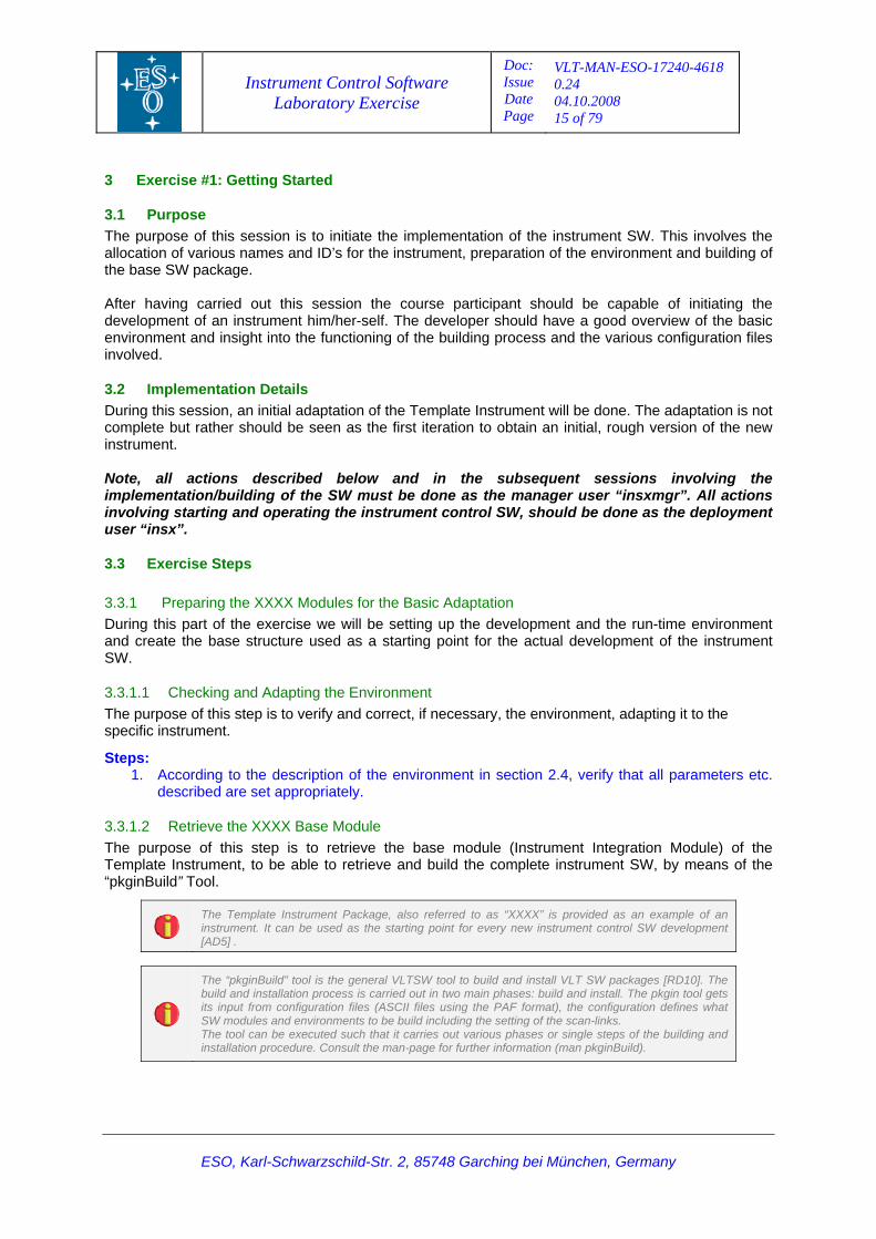
The Instrument The Exercise Instrument is a near-infrared imager, equipped with a narrow-band filter and a mosaic of 2 Hawaii RG detectors with a size of 512x512 pixels and a physical gap of 20µ. The light passes one filter wheel before reaching the detector. It has a calibration unit composed by a technical detector, one sodium lamp, one halogen lamp with intensity control and one dichroic mirror. The cryogenic variables (temperatures, vacuum, etc) are monitored by a Yokogawa controller. There is an entrance shutter to protect the instrument optical components from dust. This instrument is intended for the VLT at the Cassegrain focus.
Hardware Architecture
2.2.1 Devices The Exercise Instrument is composed of the following components:
• 6 devices, controlled by the ICS on 1 LCU: • 2 motors. • 1 entrance shutter. • 2 lamps. • 1 DAQ unit (Yokogawa).
• 1 scientific detector: • 1 NGC controller (infrared SW).
• 1 technical detector: • 1 NGTCCD.
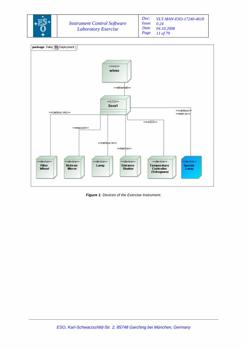
2.2.2 Computers and Hardware The Exercise Instrument is using the following computers and HW1:
• Instrument WS (running in a virtual machine). Environment name: “winsx”. • ICS LCU 1. Environment name: “linics1”. Installed boards:
• 1 Motorola MVME-6100 PowerPC CPU. • 1 MEN VME carrier board A201S. • 1 ESD CAN 04. • 1 MACCON MAC4-INC. • 1 Servo Amplifier Board VME4SA.
1 Although this equipment was used during the INS SW Workshop 2008 exercise, it is possible to carry out the exercise with only an IWS (could be a virtual machine) or an IWS together with an LCU of the current standard.
Instrument Control Software Laboratory Exercise
Doc: Issue Date Page
VLT-MAN-ESO-17240-4618 0.24 04.10.2008 11 of 79
Figure 1: Devices of the Exercise Instrument.
ESO, Karl-Schwarzschild-Str. 2, 85748 Garching bei München, Germany
Instrument Control Software Laboratory Exercise
Doc: Issue Date Page
VLT-MAN-ESO-17240-4618 0.24 04.10.2008 12 of 79
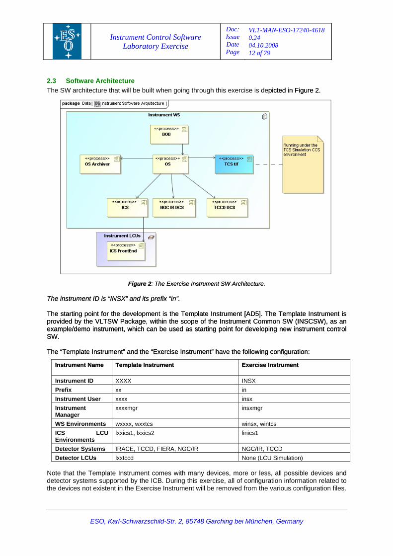
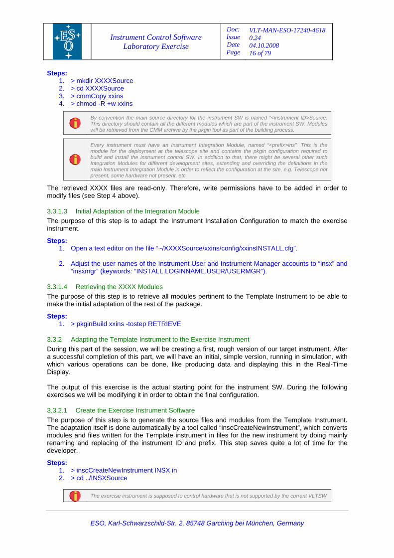
2.3 Software Architecture The SW architecture that will be built when going through this exercise is depicted in Figure 2. picted in Figure 2.
Figure 2: The Exercise Instrument SW Architecture. Figure 2: The Exercise Instrument SW Architecture. The instrument ID is “INSX” and its prefix “in”. The instrument ID is “INSX” and its prefix “in”. The starting point for the development is the Template Instrument [AD5]. The Template Instrument is provided by the VLTSW Package, within the scope of the Instrument Common SW (INSCSW), as an example/demo instrument, which can be used as starting point for developing new instrument control SW.
The starting point for the development is the Template Instrument
[AD5]. The Template Instrument is provided by the VLTSW Package, within the scope of the Instrument Common SW (INSCSW), as an example/demo instrument, which can be used as starting point for developing new instrument control SW.
The “Template Instrument” and the “Exercise Instrument” have the following configuration: The “Template Instrument” and the “Exercise Instrument” have the following configuration:
Instrument Name Instrument Name Template InstrumentTemplate Instrument
Exercise Instrument Exercise Instrument
Instrument ID XXXX INSX Prefix xx in Instrument User xxxx insx Instrument Manager
xxxxmgr insxmgr
WS Environments wxxxx, wxxtcs winsx, wintcs ICS LCU Environments
lxxics1, lxxics2 linics1
Detector Systems IRACE, TCCD, FIERA, NGC/IR NGC/IR, TCCD Detector LCUs lxxtccd None (LCU Simulation)
Note that the Template Instrument comes with many devices, more or less, all possible devices and detector systems supported by the ICB. During this exercise, all of configuration information related to the devices not existent in the Exercise Instrument will be removed from the various configuration files.
ESO, Karl-Schwarzschild-Str. 2, 85748 Garching bei München, Germany
Instrument Control Software Laboratory Exercise
Doc: Issue Date Page
VLT-MAN-ESO-17240-4618 0.24 04.10.2008 13 of 79
The mapping of environments used by XXXX and INSX is shown in the following table:
Environment Number
Template Instrument Exercise Instrument
1 wxxxx winsx 2 lxxics1 linics1 3 lxxics2 - 4 lxxtccd -
2.4 Environment Configuration
This section describes the configuration of the IWS. Apart from some definitions of the environment variables in PECS files, e.g. RTAPENV and TCS_ENVNAME, that have to be set by the instrument SW developer, all the remaining configuration should be done by the user “vltmgr” during the installation of the VLT SW. The configuration given below is just a check-list in case that there are some fundamental problems on the IWS.
2.4.1 User Accounts/Environments The Instrument User Accounts should be declared as usual on the WS (Linux based). The entry in “/etc/passwd” should be something like this:
insx:x:4929:300:(c/a vltmgr):/home/insx:/bin/bash insxmgr:x:4932:300:(c/a vltmgr):/home/insxmgr:/bin/bash
For each instrument there is a deployment user under which the SW is running and a manager account, under which the SW is being developed, built and installed [AD3]. These account should be named according to the instrument, e.g. in the case of the exercise instrument, “insx” and “insxmgr” [AD3]
For the Instrument Manager Account, “insxmgr”, the following environment variables should be defined in PECS (e.g. “/home/insamgr/.pecs/apps-all.env”), e.g.:
export INTROOT=/vlt/INSX/INTROOT export PATH=$INTROOT/bin:$PATH export LD_LIBRARY_PATH=$INTROOT/lib:$LD_LIBRARY_PATH export INS_ROOT=/data/INSX/INS_ROOT export INS_USER=SYSTEM export TARGET=LAB_EX export RTAPENV=winsx export DHS_DATA=$INS_ROOT/SYSTEM/DETDATA export TCS_ENVNAME=wintcs
To simplify the configuration of the deployment user, here “insx”, a link is normally created, which points to the definition for the Manager Account, e.g.:
/home/insx/.pecs/apps-all.env -> /home/insxmgr/.pecs/apps-all.env
The VLTSW building tool (“pkgin”) is depending on having the Instrument Manager Account user executing remote shell commands as the Instrument User. It is therefore necessary to add entries in the “~insx/.rhosts” definition of the Instrument User to allow this, e.g.:
te77.hq.eso.org insx te77.hq.eso.org insxmgr
The global user account on the VxWorks based LCUs, is called “vx”. It is important to add an entry in the “~vx/.rhosts” definition to make it possible for the “vx” user on the LCU to access and boot the VxWorks kernel, e.g.:
linics1 vx linics1.hq.eso.org vx lintccd vx licics1.hq.eso.org vx
ESO, Karl-Schwarzschild-Str. 2, 85748 Garching bei München, Germany

Instrument Control Software Laboratory Exercise
Doc: Issue Date Page
VLT-MAN-ESO-17240-4618 0.24 04.10.2008 14 of 79
2.4.2 CCS/LCC Environments The basic configuring is described in this section. A CCS environment (or RTAP Environment), must have an entry in “/etc/services”, reserving a unique port number for the command channel, e.g.:
winsx 2302/tcp
Also, for the VxWorks based LCUs, there should be an entry per environment: linics1 2160/tcp lintccd 2160/tcp
Note that LCU’s always have the same port defined (2160). In order to register properly the environments in the CCS framework, the environments must be defined in the ACC DB. The ACC DB is managed by the “vltmgr” account.
Access and Configuration Control (ACC) DB is relational SQL-based database containing a centralized configuration for the nodes, CCS and LCU environments in the control network and the relation between them. This configuration data can be queried at run-time by the engineering interfaces and VLT applications [RD13].
This is done by inserting the following lines in the SQL script, “/vltdata/msql/accData.sql”: … INSERT INTO prog_environment VALUES ('winsx','','QSEMU',2302,'te77','','','',0)\g … INSERT INTO station VALUES ('linics1','','vltsoft','134.171.24.75','','AH','VLT','','','ppc','PPC604','mv6100',0)\g … INSERT INTO prog_environment VALUES('linics1','','LCU',2160,'linics1','','','',0 ) \g … # linics1 boots from winsx. INSERT INTO lcu_progenv VALUES ('linics1' ,'winsx' ) \g …
The ACC SQL script must be loaded into the ACC RDBMS by invoking the command “accLoadData” as user “vltmgr”.
The “vltmgr” account is defined on all VLT machines and it has special privileges to install and configure VLTSW and configuration files which are write protected for the other users. Among other things, this manager account can, for instance, modify the ACC DB and update the VLTSW installation.
After having loaded the ACC DB definition, it is possible to cross-check if the environments have been properly defined by means of the “vccEnv” Tool.
VLT Common Configuration Environment (VCC) is a family of engineering tools intended to create, delete, query and control the VLT environments in a uniform way. In particular, vccEnv is an interactive engineering panel which, among other things, interact with the ACC server to retrieve the information about the CCS and LCU environments.
ESO, Karl-Schwarzschild-Str. 2, 85748 Garching bei München, Germany
Instrument Control Software Laboratory Exercise
Doc: Issue Date Page
VLT-MAN-ESO-17240-4618 0.24 04.10.2008 15 of 79
3 Exercise #1: Getting Started
3.1
3.2
3.3
Purpose The purpose of this session is to initiate the implementation of the instrument SW. This involves the allocation of various names and ID’s for the instrument, preparation of the environment and building of the base SW package. After having carried out this session the course participant should be capable of initiating the development of an instrument him/her-self. The developer should have a good overview of the basic environment and insight into the functioning of the building process and the various configuration files involved.
Implementation Details During this session, an initial adaptation of the Template Instrument will be done. The adaptation is not complete but rather should be seen as the first iteration to obtain an initial, rough version of the new instrument. Note, all actions described below and in the subsequent sessions involving the implementation/building of the SW must be done as the manager user “insxmgr”. All actions involving starting and operating the instrument control SW, should be done as the deployment user “insx”.
Exercise Steps
3.3.1 Preparing the XXXX Modules for the Basic Adaptation During this part of the exercise we will be setting up the development and the run-time environment and create the base structure used as a starting point for the actual development of the instrument SW.
3.3.1.1 Checking and Adapting the Environment The purpose of this step is to verify and correct, if necessary, the environment, adapting it to the specific instrument.
Steps: 1. According to the description of the environment in section 2.4, verify that all parameters etc.
described are set appropriately.
3.3.1.2 Retrieve the XXXX Base Module The purpose of this step is to retrieve the base module (Instrument Integration Module) of the Template Instrument, to be able to retrieve and build the complete instrument SW, by means of the “pkginBuild” Tool.
The Template Instrument Package, also referred to as “XXXX” is provided as an example of an instrument. It can be used as the starting point for every new instrument control SW development [AD5] .
The “pkginBuild” tool is the general VLTSW tool to build and install VLT SW packages [RD10]. The build and installation process is carried out in two main phases: build and install. The pkgin tool gets its input from configuration files (ASCII files using the PAF format), the configuration defines what SW modules and environments to be build including the setting of the scan-links. The tool can be executed such that it carries out various phases or single steps of the building and installation procedure. Consult the man-page for further information (man pkginBuild).
ESO, Karl-Schwarzschild-Str. 2, 85748 Garching bei München, Germany
Instrument Control Software Laboratory Exercise
Doc: Issue Date Page
VLT-MAN-ESO-17240-4618 0.24 04.10.2008 16 of 79
Steps: 1. > mkdir XXXXSource 2. > cd XXXXSource 3. > cmmCopy xxins 4. > chmod -R +w xxins
By convention the main source directory for the instrument SW is named “<instrument ID>Source. This directory should contain all the different modules which are part of the instrument SW. Modules will be retrieved from the CMM archive by the pkgin tool as part of the building process.
Every instrument must have an Instrument Integration Module, named “<prefix>ins”. This is the module for the deployment at the telescope site and contains the pkgin configuration required to build and install the instrument control SW. In addition to that, there might be several other such Integration Modules for different development sites, extending and overriding the definitions in the main Instrument Integration Module in order to reflect the configuration at the site, e.g. Telescope not present, some hardware not present, etc.
The retrieved XXXX files are read-only. Therefore, write permissions have to be added in order to modify files (see Step 4 above).
3.3.1.3 Initial Adaptation of the Integration Module The purpose of this step is to adapt the Instrument Installation Configuration to match the exercise instrument.
Steps: 1. Open a text editor on the file “~/XXXXSource/xxins/config/xxinsINSTALL.cfg”.
2. Adjust the user names of the Instrument User and Instrument Manager accounts to “insx” and
“insxmgr” (keywords: “INSTALL.LOGINNAME.USER/USERMGR”).
3.3.1.4 Retrieving the XXXX Modules The purpose of this step is to retrieve all modules pertinent to the Template Instrument to be able to make the initial adaptation of the rest of the package.
Steps: 1. > pkginBuild xxins -tostep RETRIEVE
3.3.2 Adapting the Template Instrument to the Exercise Instrument During this part of the session, we will be creating a first, rough version of our target instrument. After a successful completion of this part, we will have an initial, simple version, running in simulation, with which various operations can be done, like producing data and displaying this in the Real-Time Display. The output of this exercise is the actual starting point for the instrument SW. During the following exercises we will be modifying it in order to obtain the final configuration.
3.3.2.1 Create the Exercise Instrument Software The purpose of this step is to generate the source files and modules from the Template Instrument. The adaptation itself is done automatically by a tool called “inscCreateNewInstrument”, which converts modules and files written for the Template instrument in files for the new instrument by doing mainly renaming and replacing of the instrument ID and prefix. This step saves quite a lot of time for the developer.
Steps: 1. > inscCreateNewInstrument INSX in 2. > cd ../INSXSource
The exercise instrument is supposed to control hardware that is not supported by the current VLTSW
ESO, Karl-Schwarzschild-Str. 2, 85748 Garching bei München, Germany
Instrument Control Software Laboratory Exercise
Doc: Issue Date Page
VLT-MAN-ESO-17240-4618 0.24 04.10.2008 17 of 79
release VLT2008, e.g. NGC detectors and Yokogawa DAQ Station. Also, there have been many improvements and bug fixes since the last official release that are needed for the exercise. For that reason, the latest SW has to be installed on top of the existing VLTROOT. The convention is to list the modules in file named “inins/config/ininsINSTALL_VLTSW.<VLTSWRelease>.cfg”. Since the current release is VLT2008, the file name is “ininsINSTALL_VLTSW.VLT2008.cfg”. This file is automatically searched for and, if exists, appended by the “pkginBuild” tool.
The NGC SW is not supported in VLT2008 release and it takes long time to compile it. In order to minimize the compilation time during the lab exercises, the latest NGC SW has already been installed in the VLTROOT.
3.3.2.2 Adapt the Installation Configuration File The purpose of this step is to adapt the Instrument Installation Configuration what concerns the CCS Environments, LCC Environment and the CCS Scan System. In addition the detector systems provided by the system are defined.
For further information about CCS services consult the CCS User Manual.
Steps: 1. Open the “~/INSXSource/inins/config/ininsINSTALL.cfg” configuration file in a text editor.
2. Remove MC68040 from “INSTALL.MODULE.CPU” since we are not using this board.
3. We will work only with the “winsx”, “linics1” and “wintcs” environments. Add line:
INSTALL.ENVS.AVAIL "winsx linics1 wintcs"
below the “INSTALL.LCUENV3.*” block, to signal which environments to build and use.
4. Remove IRACE and FIERA detectors from the system. Comment out the entries for “INSTALL.DET1” and “INSTALL.DET3” (“DET1” will become the NGC/IR detector system in the exercise instrument).
5. Remove the module “indirdcs” from the list of modules to install. Comment out the keywords
“INSTALL.MODULE35.*”.
6. Set keyword “INSTALL.SCAN5.REMOTEENV” to “wintcs”.
7. Add this line at the top of the installation configuration after the existing “APPEND” keyword to have the TCS Simulator included in the configuration:
INSTALL.APPEND2.FILE "ininsINSTALL_TCSSIM.cfg";
3.3.2.3 Adapting the TCS Simulator Configuration The purpose of this step is to configure the TCS Simulator to make it ready for usage in connection with the exercise instrument. The TCS Simulator will be running on the same WS as the instrument SW.
Steps: 1. Open the TCS Simulation Configuration File,
“~/INSXSource/inins/config/ininsINSTALL_TCSSIM.cfg”, with a text editor.
2. Add/Change the following lines to the file :
# NOTE: RTAPENV1 - winsx INSTALL.RTAPENV2.NAME "wintcs"; INSTALL.RTAPENV2.TPLSRC "inins/ENVIRONMENTS/wintcs"; # Installation Hook for the TCS Simulation Package. INSTALL.HOOK2.NAME "AFTER_CREATE_SCAN";
ESO, Karl-Schwarzschild-Str. 2, 85748 Garching bei München, Germany
Instrument Control Software Laboratory Exercise
Doc: Issue Date Page
VLT-MAN-ESO-17240-4618 0.24 04.10.2008 18 of 79
INSTALL.HOOK2.PLUGIN "tcssimInstall.sh";
3.3.2.4 Adapt the Instrument Configuration The purpose of this step is to carry out the basic (initial) adaptation of the Instrument Configuration File in order to make it possible to build our instrument. The end result is only a minor step towards the final solution. i.e., further adaptation will have to be done at a later stage.
The INS framework provides the skeleton of the instrumentation SW that can be customized by an instrument developer through configuration files.
Steps: 1. Open the Instrument Configuration File, “~/INSXSource/MS/inmcfg/config/inmcfgINS.cfg”, with
a text editor.
2. Locate the keyword “INS.CON.LCUENV2” and add this line:
INS.CON.LCUAV2 F; # LCU 2 not available Normally this configuration file should be cleaned up completely, i.e. all unused devices removed, the documentation in the source file updated, e.g. the table showing the devices, etc. Due to time constraints we will refrain from doing a complete update at this point. During the next session we will continue the adaptation of the Instrument Configuration File.
3.3.2.5 Adapt the Start-up Configuration The purpose of this step is to adapt the Instrument Start-Up Configuration to make it possible to start our first, rough version of INSX.
The Instrument Start-Up Configuration defines how to start-up and initialize the various components constituting the instrument.
Steps: 1. Open the Start-up Configuration, “~/INSXSource/MS/inmcfg/config/inmcfgSTART.cfg”, in a
text editor.
2. Put “OCS.DET1.ACCESS” and “OCS.DET3.ACCESS” to “IGNORE”, as we don’t want to start up the IRACE and FIERA detector systems.
3.3.2.6 Build the SW for the Exercise Instrument The purpose of this step is to actually build and generate all the bits and pieces of object files and libraries, DB configuration files, etc. which make up the first version of INSX. Furthermore, the various CCS and LCU Environments involved are created and initialized.
Steps: 1. > cd ~/INSXSource
2. > pkginBuild inins
The above step will take a while, so please be patient.
3.3.2.7 Start the Instrument The purpose of this step is to start-up the initial instrument and to verify that the environment and the SW components etc. involved seem to be correctly generated from the configurations.
Steps: 1. Login in to the IWS as user “insx”.
2. > ininsStart
ESO, Karl-Schwarzschild-Str. 2, 85748 Garching bei München, Germany
Instrument Control Software Laboratory Exercise
Doc: Issue Date Page
VLT-MAN-ESO-17240-4618 0.24 04.10.2008 19 of 79
3. In the INSX Control Panel appearing, start the INSX Engineering Panel (Engineering -> GUI) and bring the following subsystems ONLINE: TCCD DCS, NGC/IR and ICS.
4. Shut down the instrument by invoking the shut-down tool, “ininsStop”.
Scripts “ininsStart” and “ininsStop” are start up tools encapsulating a generic tool based on the “osb” and “stoo” packages.
The basic GUIs provided at this stage, should merely be seen as simple implementations of the actual GUIs, which will have to be implemented for the real deployment of the instrument at the telescope.
3.4 Session Summary During this exercise we have made the very basic preparations to start building the Exercise Instrument. We set up the environment, retrieved the Instrument Integration Module of the Template Instrument Package and adapted the very basic parameters. Then we retrieved the rest of the modules, pertinent to the Template Instrument from CMM, and did all necessary renaming using the provided tools. Finally, we rebuilt the SW and executed the very first start-up and shutdown procedures. Note, normally at this stage in the project, we should create the CMM modules pertinent to the INSX Instrument in CMM. Due to the logistics handling of this, we will refrain from doing this in connection with this exercise. What we have now is an intermediate version of the instrument. It is possible to start the instrument and do various basic actions, everything in simulation. In the next sessions we will be looking into implementing more specific details of the instrument.
ESO, Karl-Schwarzschild-Str. 2, 85748 Garching bei München, Germany
Instrument Control Software Laboratory Exercise
Doc: Issue Date Page
VLT-MAN-ESO-17240-4618 0.24 04.10.2008 20 of 79
4 Exercise #2: Instrument Control Software - ICS
4.1
4.2
Purpose The purpose of this session is to implement the Instrument Control SW, ICS, of the instrument. The device configuration of XXXX, which we modified slightly during the first session, will be adapted to reflect the exact configuration of INSX. During this session the course participant will get a walk-through the details related to the ICS. It will provide an overview of configuration parameters for various devices and how these are mapped into the running ICS. At the end of the session, the ICS of the instrument should be obtained, running in simulation on the ICS LCU. It should be possible to connect the real devices and let it run in the normal mode at a later stage.
Implementation Details
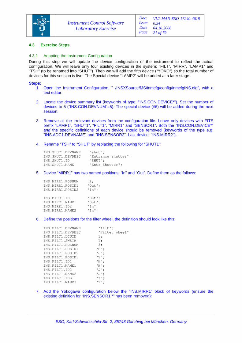
4.2.1 Devices The exercise instrument supports the following devices:
# Name FITS Prefix ICB Class LCU Details Comments
1 FILT FILT1 icbMOT_FILTER 1 Filters: H, J, Y - Filter Wheel 1
2 MIRR MIRR1 icbMOT_MIRROR 1 Positions: In, Out - Mirror 1
3 LAMP1 LAMP1 icbLAMP 1 On/off. - Lamp 1
4 SHUT SHUT1 icbSHUTTER 1 Open/closed. - Shutter 1
5 YOKO SENSOR1 icbSEN_DX200 1 - - Yokogawa DAQ Station 1
6 LAMP2 LAMP2 N/A 1 Digital and Analog I/O control
Special device. Lamp with intensity control currently not supported by the lamp standard device.
Note, the Special Device, “LAMP2”, will not be implemented during this session.
A “Standard Device” is a hardware device for which a driver is provided by the VLTSW and no coding is needed to incorporate it into an instrument. The term “Special Device” is used to describe an application that has to be developed in order to control hardware that is not supported by the VLTSW.
4.2.2 Location of Relevant Configuration Files To add/remove a device to/from a VLT instrument the following configuration files should be adjusted:
1. Device configuration; file “inmcfgINS.cfg”.
2. Instrument DB; files “iniEnv1.db” and “iniEnv.db”.
3. Scan links; file “linics1.scan”.
4. LCU default DB configuration; file “iniConfigLib.tcl”.
5. WS simulation DB; file “iniSIM_CONTROL.class”.
6. Instrument Dictionary; files “dicINSX*.txt”.
ESO, Karl-Schwarzschild-Str. 2, 85748 Garching bei München, Germany
Instrument Control Software Laboratory Exercise
Doc: Issue Date Page
VLT-MAN-ESO-17240-4618 0.24 04.10.2008 21 of 79
ESO, Karl-Schwarzschild-Str. 2, 85748 Garching bei München, Germany
4.3 Exercise Steps
4.3.1 Adapting the Instrument Configuration During this step we will update the device configuration of the instrument to reflect the actual configuration. We will leave only four existing devices in the system: “FILT”, “MIRR”, “LAMP1” and “TSH” (to be renamed into “SHUT”). Then we will add the fifth device (“YOKO”) so the total number of devices for this session is five. The Special device “LAMP2” will be added at a later stage.
Steps: 1. Open the Instrument Configuration, "~/INSXSource/MS/inmcfg/config/inmcfgINS.cfg", with a
text editor.
2. Locate the device summary list (keywords of type: "INS.CON.DEVICE*"). Set the number of devices to 5 ("INS.CON.DEVNUM"=5). The special device (#6) will be added during the next session.
3. Remove all the irrelevant devices from the configuration file. Leave only devices with FITS
prefix “LAMP1”, “SHUT1”, “FILT1”, “MIRR1” and “SENSOR1”. Both the "INS.CON.DEVICE*" and the specific definitions of each device should be removed (keywords of the type e.g. "INS.ADC1.DEVNAME" and "INS.SENSOR2". Last device: "INS.MIRR2").
4. Rename “TSH” to “SHUT” by replacing the following for “SHUT1”:
INS.SHUT1.DEVNAME "shut"; INS.SHUT1.DEVDESC "Entrance shutter"; INS.SHUT1.ID "SHUT"; INS.SHUT1.NAME "Entr_Shutter";
5. Device “MIRR1” has two named positions, “In” and “Out”. Define them as the follows:
INS.MIRR1.POSNUM 2; INS.MIRR1.POSID1 "Out"; INS.MIRR1.POSID2 "In"; INS.MIRR1.ID1 "Out"; INS.MIRR1.NAME1 "Out"; INS.MIRR1.ID2 "In"; INS.MIRR1.NAME2 "In";
6. Define the positions for the filter wheel, the definition should look like this:
INS.FILT1.DEVNAME "filt"; INS.FILT1.DEVDESC "Filter wheel"; INS.FILT1.LCUID 1; INS.FILT1.SWSIM T; INS.FILT1.POSNUM 3; INS.FILT1.POSID1 "H"; INS.FILT1.POSID2 "J"; INS.FILT1.POSID3 "Y"; INS.FILT1.ID1 "H"; INS.FILT1.NAME1 "H"; INS.FILT1.ID2 "J"; INS.FILT1.NAME2 "J"; INS.FILT1.ID3 "Y"; INS.FILT1.NAME3 "Y";
7. Add the Yokogawa configuration below the “INS.MIRR1” block of keywords (ensure the
existing definition for “INS.SENSOR1.*” has been removed):
Instrument Control Software Laboratory Exercise
Doc: Issue Date Page
VLT-MAN-ESO-17240-4618 0.24 04.10.2008 22 of 79
ESO, Karl-Schwarzschild-Str. 2, 85748 Garching bei München, Germany
# # Sample YOKOGAWA DX200 DAQ Station # INS.SENSOR1.DEVNAME "yoko"; # Name of the ICS device INS.SENSOR1.DEVDESC "YOKOGAWA DX200 DAQ"; # Description of the device INS.SENSOR1.DEVTYPE "DX200"; # Device type INS.SENSOR1.LCUID 1; # Id. of the LCU managing device INS.SENSOR1.SWSIM T; # If T, function is SW simulated INS.SENSOR1.PORT "/tyCo/3"; # Hardware device INS.SENSOR1.NUM 3; # Number of managed sensor values INS.SENSOR1.NAME1 "CH1"; # Sensor value name INS.SENSOR1.DESC1 "Temp 1"; # Sensor value description INS.SENSOR1.HEADER1 F; # If T, report sensor value in image header INS.SENSOR1.FITS1 "INS.SENS1.VAL"; # Sensor value FITS keyword INS.SENSOR1.SENUNIT1 "C"; # Sensor value unit INS.SENSOR1.SENADDR1 01; # Sensor value hardware address INS.SENSOR1.LOG1 T; # If T, function is SW simulated INS.SENSOR1.NAME2 "CH2"; # Sensor value name INS.SENSOR1.DESC2 "Temp 2"; # Sensor value description INS.SENSOR1.HEADER2 F; # If T, report value in FITS header INS.SENSOR1.FITS2 "INS.SENS2.VAL"; # Sensor value FITS keyword INS.SENSOR1.SENUNIT2 "C"; # Sensor value unit INS.SENSOR1.SENADDR2 02; # Sensor value hardware address INS.SENSOR1.LOG2 T; # If T, function is SW simulated INS.SENSOR1.NAME3 "CH3"; # Sensor value name INS.SENSOR1.DESC3 "Temp 3"; # Sensor value description INS.SENSOR1.HEADER3 F; # If T, report value in image header INS.SENSOR1.FITS3 "INS.SENS3.VAL"; # Sensor value FITS keyword INS.SENSOR1.SENUNIT3 "C"; # Sensor value unit INS.SENSOR1.SENADDR3 03; # Sensor value hardware address INS.SENSOR1.LOG3 T; # If T, function is SW simulated
8. Re-number the devices in the device summary list (keywords of type: "INS.CON.DEVICE*"), according to the table listing all devices above. There should be five of them as it is shown below:
INS.CON.DEVNUM 5; # Number of ICS devices INS.CON.DEVICE1 "INS.LAMP1"; # Device FITS prefix used in the config file INS.CON.DEVICE2 "INS.SHUT1"; # Device FITS prefix used in the config file INS.CON.DEVICE3 "INS.FILT1"; # Device FITS prefix used in the config file INS.CON.DEVICE4 "INS.MIRR1"; # Device FITS prefix used in the config file INS.CON.DEVICE5 "INS.SENSOR1"; #Device FITS prefix used in the config file
9. Set all “LCUID” keywords equal to ”1”, i.e. we reassign all the devices to LCU #1.
10. Leave only the assembly that contains the word “INS.MODE” and set its index to 1. Remove
all other assemblies. If needed, they will be defined at a later stage:
# # 2.2 ICS Assemblies # # INS.MODE: # Accept any value of INS.MODE and do not forward this key to the LCUs. INS.ASSEMBLY1 "INS.MODE"; INS.ASSEMBLY1.KEY1 "*" INS.ASSEMBLY1.VAL1 ""
11. Comment out all lines containing “OCS.MODE*” keywords. These define observation modes, which will be defined during the OS session (Session 5).
Instrument Control Software Laboratory Exercise
Doc: Issue Date Page
VLT-MAN-ESO-17240-4618 0.24 04.10.2008 23 of 79
ESO, Karl-Schwarzschild-Str. 2, 85748 Garching bei München, Germany
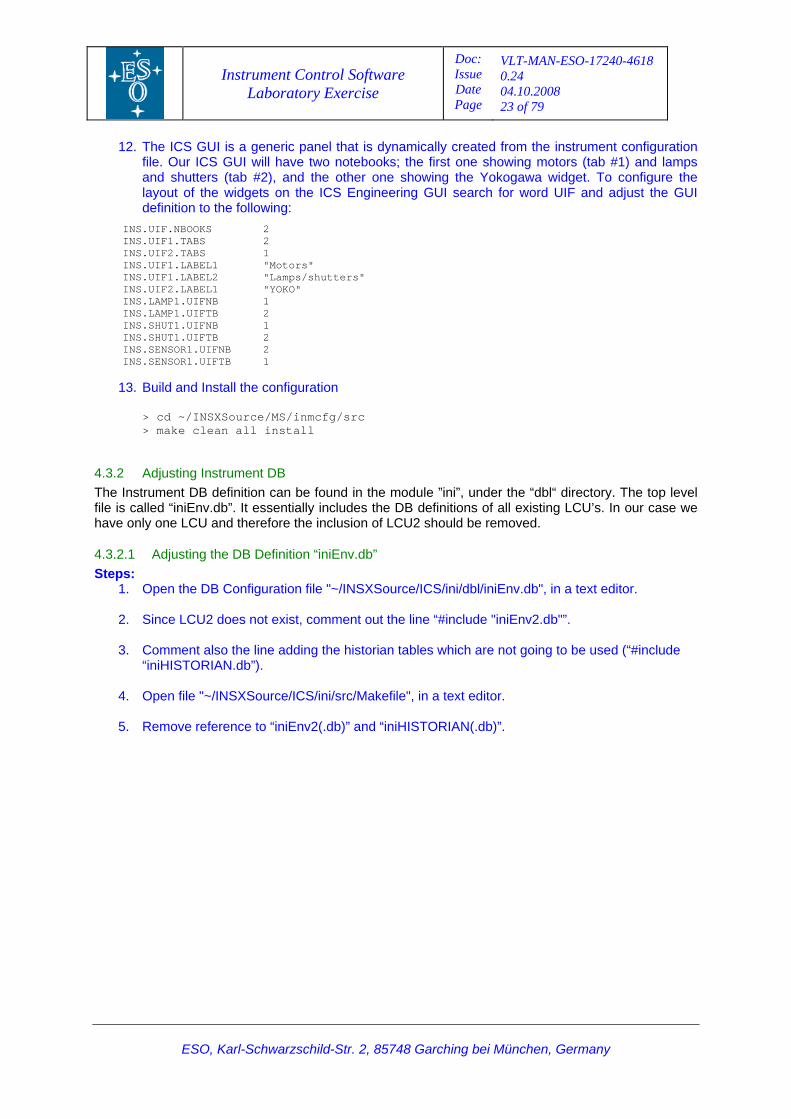
12. The ICS GUI is a generic panel that is dynamically created from the instrument configuration file. Our ICS GUI will have two notebooks; the first one showing motors (tab #1) and lamps and shutters (tab #2), and the other one showing the Yokogawa widget. To configure the layout of the widgets on the ICS Engineering GUI search for word UIF and adjust the GUI definition to the following:
INS.UIF.NBOOKS 2 INS.UIF1.TABS 2 INS.UIF2.TABS 1 INS.UIF1.LABEL1 "Motors" INS.UIF1.LABEL2 "Lamps/shutters" INS.UIF2.LABEL1 "YOKO" INS.LAMP1.UIFNB 1 INS.LAMP1.UIFTB 2 INS.SHUT1.UIFNB 1 INS.SHUT1.UIFTB 2 INS.SENSOR1.UIFNB 2 INS.SENSOR1.UIFTB 1
13. Build and Install the configuration > cd ~/INSXSource/MS/inmcfg/src > make clean all install
4.3.2 Adjusting Instrument DB The Instrument DB definition can be found in the module ”ini”, under the “dbl“ directory. The top level file is called “iniEnv.db”. It essentially includes the DB definitions of all existing LCU’s. In our case we have only one LCU and therefore the inclusion of LCU2 should be removed.
4.3.2.1 Adjusting the DB Definition “iniEnv.db” Steps:
1. Open the DB Configuration file "~/INSXSource/ICS/ini/dbl/iniEnv.db", in a text editor.
2. Since LCU2 does not exist, comment out the line “#include "iniEnv2.db"”.
3. Comment also the line adding the historian tables which are not going to be used (“#include “iniHISTORIAN.db”).
4. Open file "~/INSXSource/ICS/ini/src/Makefile", in a text editor.
5. Remove reference to “iniEnv2(.db)” and “iniHISTORIAN(.db)”.
Instrument Control Software Laboratory Exercise
Doc: Issue Date Page
VLT-MAN-ESO-17240-4618 0.24 04.10.2008 24 of 79
ESO, Karl-Schwarzschild-Str. 2, 85748 Garching bei München, Germany
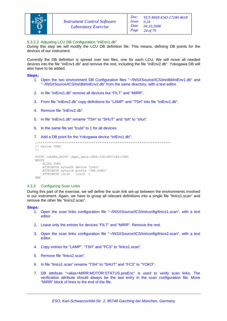
5.3.2.2 Adjusting LCU DB Configuration “iniEnv1.db” During this step we will modify the LCU DB definition file. This means, defining DB points for the devices of our instrument. Currently the DB definition is spread over two files, one for each LCU. We will move all needed devices into the file “iniEnv1.db” and remove the rest, including the file “iniEnv2.db”. Yokogawa DB will also have to be added.
Steps: 1. Open the two environment DB Configuration files "~/INSXSource/ICS/ini/dbl/iniEnv1.db" and
"~/INSXSource/ICS/ini/dbl/iniEnv2.db” from the same directory, with a text editor.
2. In file "iniEnv1.db" remove all devices but “FILT” and “MIRR”.
3. From file "iniEnv2.db" copy definitions for “LAMP” and “TSH” into file "iniEnv1.db".
4. Remove file "iniEnv2.db".
5. In file "iniEnv1.db" rename “TSH” to “SHUT” and “tsh” to “shut”.
6. In the same file set “lcuId” to 1 for all devices.
7. Add a DB point for the Yokogawa device “iniEnv1.db”: //************************************************************************ // Device YOKO // POINT icbSEN_DX200 :Appl_data:INSX:ICS:DEVICES:YOKO BEGIN ALIAS YOKO ATTRIBUTE bytes20 device "yoko" ATTRIBUTE bytes16 prefix "INS.YOKO" ATTRIBUTE int32 lcuId 1 END
4.3.3 Configuring Scan Links During this part of the exercise, we will define the scan link set-up between the environments involved in our instrument. Again, we have to group all relevant definitions into a single file “linics1.scan” and remove the other file “linics2.scan”.
Steps: 1. Open the scan links configuration file "~/INSXSource/ICS/ini/config/linics1.scan", with a text
editor.
2. Leave only the entries for devices “FILT” and “MIRR”. Remove the rest.
3. Open the scan links configuration file "~/INSXSource/ICS/ini/config/linics2.scan", with a text editor.
4. Copy entries for “LAMP”, “TSH” and “FCS” to “linics1.scan”.
5. Remove file “linics2.scan”.
6. In file “linics1.scan” rename “TSH” to “SHUT” and “FCS” to “YOKO”.
7. DB attribute “<alias>MIRR:MOTOR:STATUS.posEnc” is used to verify scan links. The
verification attribute should always be the last entry in the scan configuration file. Move “MIRR” block of lines to the end of the file.
Instrument Control Software Laboratory Exercise
Doc: Issue Date Page
VLT-MAN-ESO-17240-4618 0.24 04.10.2008 25 of 79
Having the attribute to verify scan links as the last entry in the scan configuration will ensure that others attributes are correct in case verification is successful.
4.3.4 Setting Default LCU DB Configuration Every time an LCU is rebooted, the DB configuration file “$VLTDATA/config/<LCU name>.dbcfg” (e.g. “linics1.dbcfg”) is loaded into the LCU DB. The input for the creation of this file is taken from the configuration defined in file “inmcfgINS.cfg”. The DB configuration file can be manually created by entering at command line:
> icbConfigSet INSX
It could also be manually changed and re-loaded into the LCU with following:
> dbRestore -f /vltdata/config/linics1.dbcfg
During the build process, “pkginBuild” does this automatically through the defined plug-in:
INSTALL.HOOK1.PLUGIN "icbInstallHook INSX";
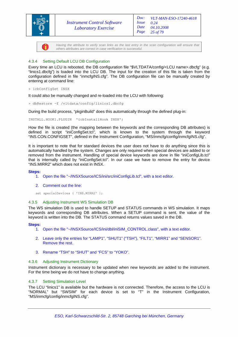
How the file is created (the mapping between the keywords and the corresponding DB attributes) is defined in script “iniConfigSet.tcl”, which is known to the system through the keyword “INS.CON.CONFIGSET”, defined in the Instrument Configuration, “MS/inmcfg/config/inmcfgINS.cfg”. It is important to note that for standard devices the user does not have to do anything since this is automatically handled by the system. Changes are only required when special devices are added to or removed from the instrument. Handling of special device keywords are done in file “iniConfigLib.tcl” that is internally called by “iniConfigSet.tcl”. In our case we have to remove the entry for device “INS.MIRR2” which does not exist in INSX.
Steps: 1. Open the file "~/INSXSource/ICS/ini/src/iniConfigLib.tcl", with a text editor.
2. Comment out the line: set specialDevices { "INS.MIRR2" };
4.3.5 Adjusting Instrument WS Simulation DB The WS simulation DB is used to handle SETUP and STATUS commands in WS simulation. It maps keywords and corresponding DB attributes. When a SETUP command is sent, the value of the keyword is written into the DB. The STATUS command returns values saved in the DB.
Steps: 1. Open the file "~/INSXSource/ICS/ini/dbl/iniSIM_CONTROL.class", with a text editor.
2. Leave only the entries for “LAMP1”, “SHUT1” (“TSH”), “FILT1”, “MIRR1” and “SENSOR1”.
Remove the rest.
3. Rename “TSH” to “SHUT” and “FCS” to “YOKO”.
4.3.6 Adjusting Instrument Dictionary Instrument dictionary is necessary to be updated when new keywords are added to the instrument. For the time being we do not have to change anything.
4.3.7 Setting Simulation Level The LCU “linics1” is available but the hardware is not connected. Therefore, the access to the LCU is “NORMAL” but “SWSIM” for each device is set to “T” in the Instrument Configuration, “MS/inmcfg/config/inmcfgINS.cfg”.
ESO, Karl-Schwarzschild-Str. 2, 85748 Garching bei München, Germany
Instrument Control Software Laboratory Exercise
Doc: Issue Date Page
VLT-MAN-ESO-17240-4618 0.24 04.10.2008 26 of 79
ESO, Karl-Schwarzschild-Str. 2, 85748 Garching bei München, Germany
Steps: 1. Open the file "~/INSXSource/MS/inmcfg/config/inmcfgSTART.cfg", with a text editor.
2. Set keyword “INS.CON.OPMODE” to “NORMAL”.
4.3.8 Adapt the “pkgin” configuration file The purpose is to correct the verification of the scanning according to the real instrument devices.
1. Open the file "~/INSXSource/inins/config/ininsINSTALL.cfg", with a text editor.
2. Change “TILT” to “MIRR” in scanning source attribute in “INSTALL.SCAN1.SRCATTR”.
4.3.9 Build and Install Updated Modules Steps:
1. > cd ~/INSXSource/ICS/ini/src
2. > make clean all install
3. > cd ~/INSXSource/MS/inmcfg/src
4. > make clean all install
4.3.10 Re-building the SW The configuration is ready for a complete rebuild. At the end, the ICS LCU will be rebooted. Execute the following lines as user “insxmgr”:
Steps: 5. > cd ~/INSXSource
6. > pkginBuild inins –fromstep BUILD_ENV
4.3.11 Starting ICS We will start the ICS and bring it ONLINE. Execute the following lines as user “insx”:
Steps: 1. > ininsStart -proc ICS
2. > ininsStart -panel ICS
3. On the ICS Control GUI select ONLINE from the ICS pull-down menu to bring the ICS
ONLINE.
4. Test the SETUP command with motors, lamps and shutters.
Instrument Control Software Laboratory Exercise
Doc: Issue Date Page
VLT-MAN-ESO-17240-4618 0.24 04.10.2008 27 of 79
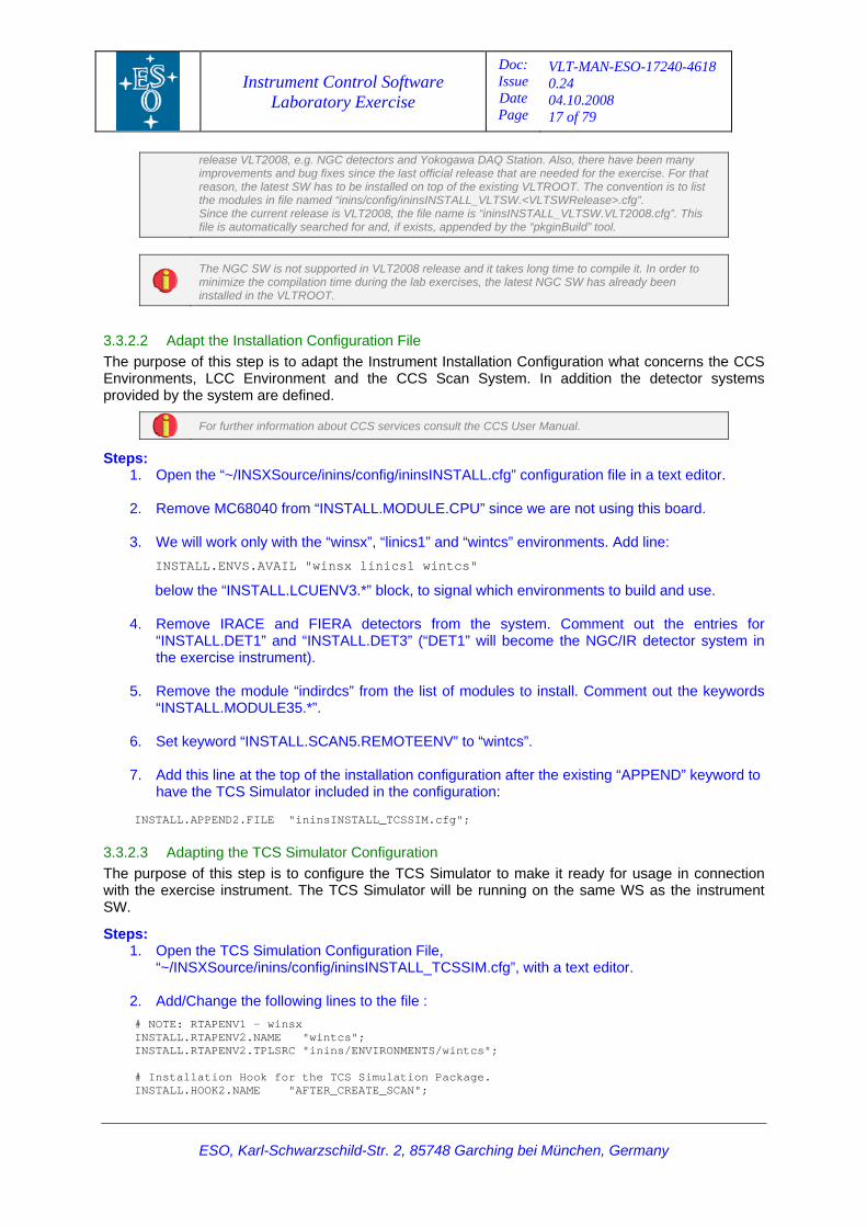
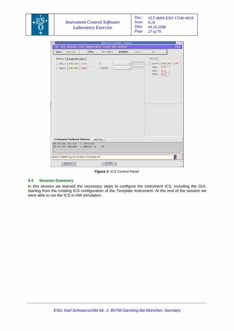
Figure 3: ICS Control Panel.
4.4 Session Summary In this session we learned the necessary steps to configure the instrument ICS, including the GUI, starting from the existing ICS configuration of the Template Instrument. At the end of the session we were able to run the ICS in HW simulation.
ESO, Karl-Schwarzschild-Str. 2, 85748 Garching bei München, Germany
Instrument Control Software Laboratory Exercise
Doc: Issue Date Page
VLT-MAN-ESO-17240-4618 0.24 04.10.2008 28 of 79
5 Exercise #3: Implementing a Special Device
5.1 Purpose The purpose of this session is to implement an LCU special device that controls a lamp with intensity control. The standard LAMP device does not support intensity control and for that reason a special device has to be implemented. In addition, a WS special device (dynamic assembly) will be implemented in order to simplify the interface with the corresponding LCU part.
It should be noted that the application created for this section does not represent the most optimal design and its sole purpose is to give a simple example how to create special devices on both LCU and WS.
Normally, the starting point for implementation of a special device would be the module xxidev which we have renamed into ixidev in Session 1. However, there are too many changes of the xxidev code required to implement our example special device. The available time for this session would not be enough for the participants of this course to complete the exercise. For that reason the complete module inilamp will be taken from the archive. The sample code supports a very basic functionally needed for the exercise, i.e. state change, setup and status. During this session the course participant will get a walk-through the details related to the implementation of the special device and the way it is incorporated into the existing instrument. At the end of the session, the complete instrument SW will be rebuilt from scratch and started. It should be possible to control the special device, in simulation, from the ICS Control panel or by sending messages. The device configuration given in this session is the one that is going to be used with the real hardware at the end of the course.
5.2 Implementation Details
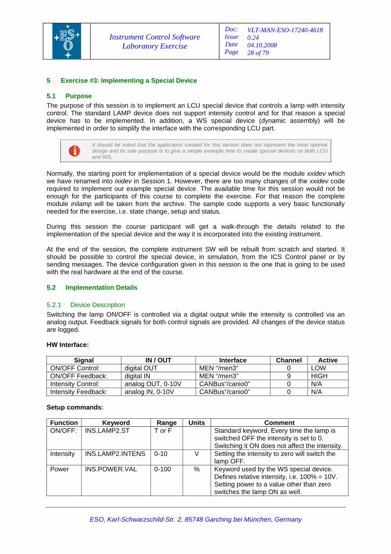
5.2.1 Device Description Switching the lamp ON/OFF is controlled via a digital output while the intensity is controlled via an analog output. Feedback signals for both control signals are provided. All changes of the device status are logged. HW Interface:
Signal IN / OUT Interface Channel Active ON/OFF Control: digital OUT MEN “/men3” 0 LOW ON/OFF Feedback: digital IN MEN “/men3” 9 HIGH Intensity Control: analog OUT, 0-10V CANBus“/canio0” 0 N/A Intensity Feedback: analog IN, 0-10V CANBus“/canio0” 0 N/A
Setup commands: Function Keyword Range Units Comment ON/OFF: INS.LAMP2.ST T or F Standard keyword. Every time the lamp is
switched OFF the intensity is set to 0. Switching it ON does not affect the intensity.
Intensity INS.LAMP2.INTENS 0-10 V Setting the intensity to zero will switch the lamp OFF.
Power INS.POWER.VAL 0-100 % Keyword used by the WS special device. Defines relative intensity, i.e. 100% = 10V. Setting power to a value other than zero switches the lamp ON as well.
ESO, Karl-Schwarzschild-Str. 2, 85748 Garching bei München, Germany
Instrument Control Software Laboratory Exercise
Doc: Issue Date Page
VLT-MAN-ESO-17240-4618 0.24 04.10.2008 29 of 79
Note: Keywords INS.LAMPi.INTENS and INS.POWER.VAL do not exist in the ICB dictionary and therefore will have to be added to the instrument dictionary.
5.2.2 Integration of the special device with the existing instrument The module inilamp represents only the special device code. However, the device has still to be integrated into the instrument. The following steps have to be completed:
1. Retrieving the inilamp module.
2. Inclusion of the inilamp module in the integration module inins, file inins/config/ininsINSTALL.cfg.
3. Update of the bootScript for the environment linics1, file inins/ENVIRONMENTS/linics1/bootScript.
4. Update of the instrument dictionary, files dicINSX/src/dicINSX_CFG.txt and dicINSX_ICS.txt.
5. Device configuration including the GUI configuration, file inmcfg/config/inmcfgINS.cfg.
6. Update of the instrument DB, file ini/dbl/iniEnv1.db.
7. Update of the scan links, file ini/config/linics1.scan.
8. Update of the simulation DB, file ini/dbl/iniSIM_CONTROL.class.
9. Automatic creation of default LCU DB configuration, files ini/src/iniConfigLib.tcl and iniConfigSet.tcl.
5.3 Exercise Steps Please note that unless explicitly stated, all steps should be executed as user insxmgr.
5.3.1 Retrieving the inilamp module: Execute the following lines as insxmgr: Steps:
1. > cd ~/INSXSource/ICS 2. > cmmCopy inilamp
NOTE: For real development cmmCopy would be replaced with: > inscRename xxidev inilamp YYYY LAMP2 xx in
5.3.2 Inclusion of the inilamp module in the integration module inins Steps:
1. Open file inins/config/ininsINSTALL.cfg with text editor. 2. Change the configuration for MODULE41 (module inidev became inilamp). Comment out the line
“INSTALL.MODULE41.VERSION …”: INSTALL.MODULE41.NAME "inilamp"; INSTALL.MODULE41.SUBPKG "ICS"; #INSTALL.MODULE41.VERSION "1.22";
5.3.3 Update of the “bootScript” for the environment “linics1”
LCU boot script is automatically generated from the definitions given as comments starting with the ‘#’ character in file “inins/ENVIRONMENTS/linics1/bootScript”. The resulting file is installed in the directory “$VLTDATA/ENVIRONMENTS/linics1”.
ESO, Karl-Schwarzschild-Str. 2, 85748 Garching bei München, Germany
Instrument Control Software Laboratory Exercise
Doc: Issue Date Page
VLT-MAN-ESO-17240-4618 0.24 04.10.2008 30 of 79
ESO, Karl-Schwarzschild-Str. 2, 85748 Garching bei München, Germany
Steps: 1. Open file inins/ENVIRONMENTS/linics1/bootScript with text editor. 2. Modify the following two lines as shown below. The lines define the drivers and modules that
get installed during the boot process. Note that special device modules, in this case module inilamp, must be declared before module icb in vUsrmodlist. # vSysmodlist: lcudrv lculog lqs mendrv canstack canstackLib canio canrmc ampl ikon iser mcon tim lcc cai scan # vUsrmodlist: inducer mcm inilamp icb
5.3.4 Update of the instrument dictionary We have introduced three new keywords: the configuration keyword INS.LAMPi.BITDEVi (will be described in the following section 5.3.5) and the setup keywords INSi.LAMPi.INTENS and INSi.POWER.VAL. They should be added to files dicINSX_CFG.txt and dicINSX_ICS.txt respectively. Steps:
1. Open file “dicINSX/src/dicINSX_CFG.txt” with text editor and add the following lines:
INSi.LAMPi.BITDEVi %15s Device used for corresponding SIGBIT (c). Device used for corresponding SIGBIT. Used to define device for each bit. Examples "/men3", "canio2". 2. Open file dicINSX/src/dicINSX_ICS.txt with text editor and add the following keyword
definitions just below keyword INSi.LAMPi.ST: INSi.LAMPi.INTENS %.2f Lamp intensity [V] (hs). Lamp intensity in Volts. Range 0-10V. INSi.POWER.VAL %.2f Lamp power [%] (hs). Lamp power expressed as percentage of full power. Range 0-100%, corresponds to intensity 0-10V.
5.3.5 Device configuration: Steps:
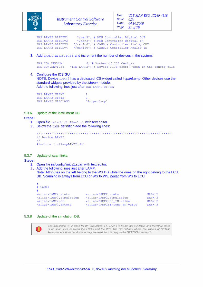
1. Open file inmcfg/config/inmcfgINS.cfg with text editor. 2. Add the following lines just after LAMP1:
# # Special lamp # INS.LAMP2.DEVNAME "lamp2"; # Name of the ICS device INS.LAMP2.DEVDESC "Special lamp"; # Description of the ICS device INS.LAMP2.DEVTYPE "S_LAMP"; # Device type INS.LAMP2.PROCNAME "inilampServer"; # Name of the LCU server process INS.LAMP2.LCUID 1; # Id. of the LCU managing the device INS.LAMP2.SWSIM T; # If T, function is software simulated INS.LAMP2.ID "LAMP2"; INS.LAMP2.NAME "Special_Lamp"; # A/D I/O interface setup INS.LAMP2.SIGBIT1 0; # on_OUT control signal INS.LAMP2.SIGBIT2 9; # on_IN feedback signal INS.LAMP2.SIGBIT3 0; # intens_OUT control signal INS.LAMP2.SIGBIT4 0; # intens_IN feedback signal
Instrument Control Software Laboratory Exercise
Doc: Issue Date Page
VLT-MAN-ESO-17240-4618 0.24 04.10.2008 31 of 79
INS.LAMP2.BITDEV1 "/men3"; # MEN Controller Digital OUT INS.LAMP2.BITDEV2 "/men3"; # MEN Controller Digital IN INS.LAMP2.BITDEV3 "/canio0"; # CANBus Controller Analog OUT INS.LAMP2.BITDEV4 "/canio0"; # CANBus Controller Analog IN
3. Add LAMP2 as DEVICE6 and increment the number of devices in the system: INS.CON.DEVNUM 6; # Number of ICS devices INS.CON.DEVICE6 "INS.LAMP2"; # Device FITS prefix used in the config file
4. Configure the ICS GUI: NOTE: Device LAMP2 has a dedicated ICS widget called inipanLamp. Other devices use the standard widgets provided by the icbpan module. Add the following lines just after INS.LAMP1.UIFTB: INS.LAMP2.UIFNB 1 INS.LAMP2.UIFTB 2 INS.LAMP2.UIFCLASS "inipanLamp"
5.3.6 Update of the instrument DB Steps:
1. Open file ini/dbl/iniEnv1.db with text editor. 2. Below the LAMP definition add the following lines:
//************************************************************************ // Device LAMP2 // #include "inilampLAMP2.db"
5.3.7 Update of scan links: Steps:
1. Open file ini/config/linics1.scan with text editor. 2. Add the following lines just after LAMP.
Note: Attributes on the left belong to the WS DB while the ones on the right belong to the LCU DB. Scanning is always from LCU or WS to WS, never from WS to LCU. # # LAMP2 # <alias>LAMP2.state <alias>LAMP2.state SRBX 2 <alias>LAMP2.simulation <alias>LAMP2.simulation SRBX 2 <alias>LAMP2.on <alias>LAMP2:on_IN.value SRBX 2 <alias>LAMP2.intens <alias>LAMP2:intens_IN.value SRBX 2
5.3.8 Update of the simulation DB:
The simulation DB is used for WS simulation, i.e. when LCU’s are not available, and therefore there is no scan links between the LCU’s and the WS. The DB defines where the values of SETUP keywords are stored and where they are read from in reply to the STATUS command.
ESO, Karl-Schwarzschild-Str. 2, 85748 Garching bei München, Germany
Instrument Control Software Laboratory Exercise
Doc: Issue Date Page
VLT-MAN-ESO-17240-4618 0.24 04.10.2008 32 of 79
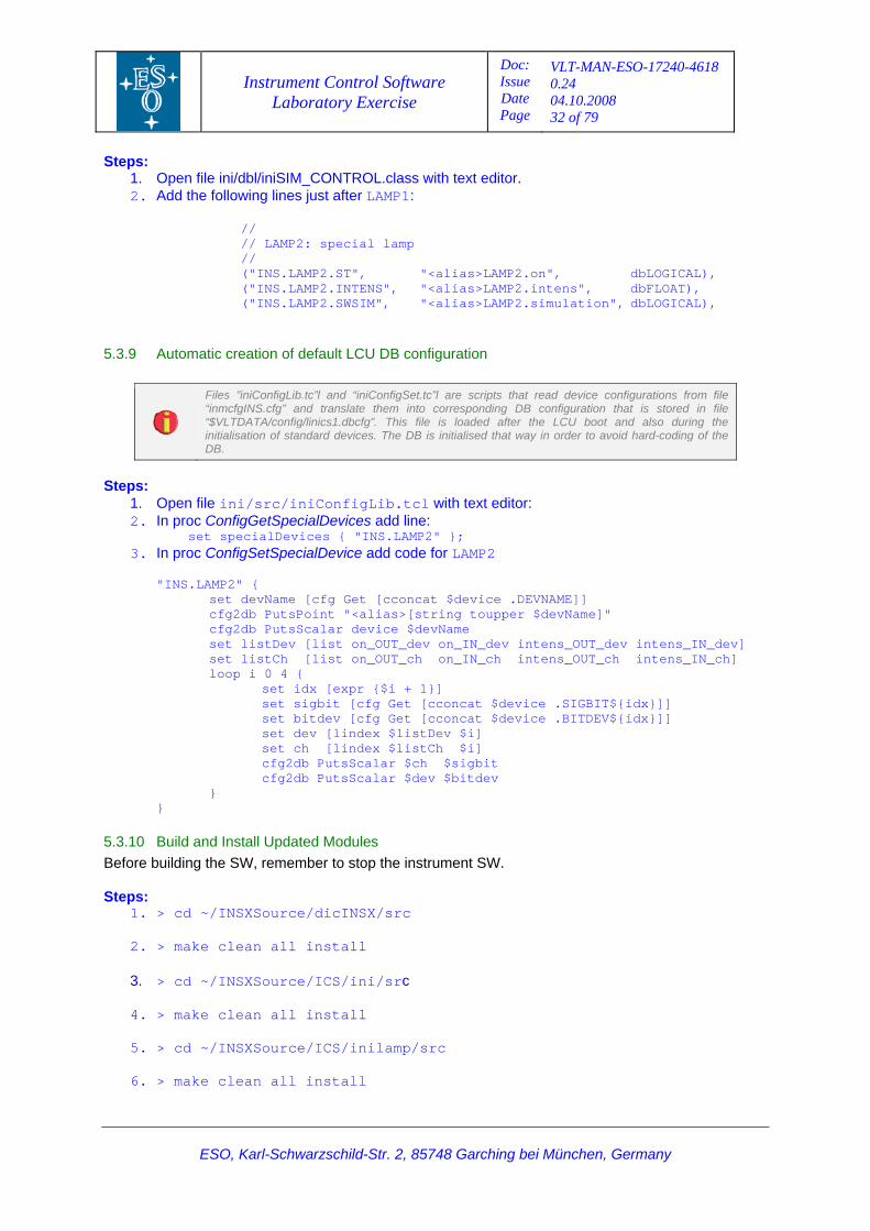
Steps: 1. Open file ini/dbl/iniSIM_CONTROL.class with text editor. 2. Add the following lines just after LAMP1:
// // LAMP2: special lamp // ("INS.LAMP2.ST", "<alias>LAMP2.on", dbLOGICAL), ("INS.LAMP2.INTENS", "<alias>LAMP2.intens", dbFLOAT), ("INS.LAMP2.SWSIM", "<alias>LAMP2.simulation", dbLOGICAL),
5.3.9 Automatic creation of default LCU DB configuration
Files ”iniConfigLib.tc”l and “iniConfigSet.tc”l are scripts that read device configurations from file “inmcfgINS.cfg” and translate them into corresponding DB configuration that is stored in file “$VLTDATA/config/linics1.dbcfg”. This file is loaded after the LCU boot and also during the initialisation of standard devices. The DB is initialised that way in order to avoid hard-coding of the DB.
Steps:
1. Open file ini/src/iniConfigLib.tcl with text editor: 2. In proc ConfigGetSpecialDevices add line:
set specialDevices { "INS.LAMP2" }; 3. In proc ConfigSetSpecialDevice add code for LAMP2
"INS.LAMP2" { set devName [cfg Get [cconcat $device .DEVNAME]] cfg2db PutsPoint "<alias>[string toupper $devName]" cfg2db PutsScalar device $devName set listDev [list on_OUT_dev on_IN_dev intens_OUT_dev intens_IN_dev] set listCh [list on_OUT_ch on_IN_ch intens_OUT_ch intens_IN_ch] loop i 0 4 { set idx [expr {$i + 1}] set sigbit [cfg Get [cconcat $device .SIGBIT${idx}]] set bitdev [cfg Get [cconcat $device .BITDEV${idx}]] set dev [lindex $listDev $i] set ch [lindex $listCh $i] cfg2db PutsScalar $ch $sigbit cfg2db PutsScalar $dev $bitdev } }
5.3.10 Build and Install Updated Modules Before building the SW, remember to stop the instrument SW. Steps:
1. > cd ~/INSXSource/dicINSX/src 2. > make clean all install
3. > cd ~/INSXSource/ICS/ini/src
4. > make clean all install
5. > cd ~/INSXSource/ICS/inilamp/src
6. > make clean all install
ESO, Karl-Schwarzschild-Str. 2, 85748 Garching bei München, Germany
Instrument Control Software Laboratory Exercise
Doc: Issue Date Page
VLT-MAN-ESO-17240-4618 0.24 04.10.2008 33 of 79
7. > cd ~/INSXSource/MS/inmcfg/src
8. > make clean all install
9. > icbConfigSet INSX
5.3.11 Verification - Rebuilding and restarting the instrument software Steps:
1. As user insxmgr: > cd ~/INSXSource > pkginBuild inins –fromstep BUILD_ENV
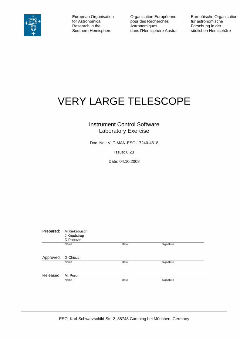
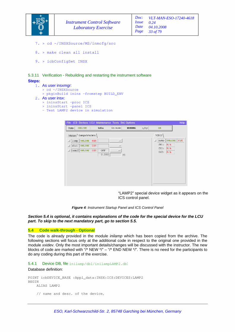
2. As user insx: > ininsStart –proc ICS > ininsStart –panel ICS - Test LAMP2 device in simulation
ESO, Karl-Schwarzschild-Str. 2, 85748 Garching bei München, Germany
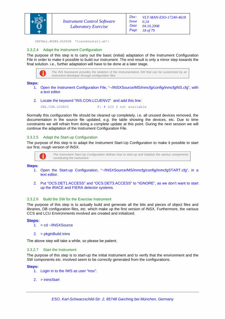
“LAMP2” special device widget as it appears on the ICS control panel.
Figure 4: Instrument Startup Panel and ICS Control Panel Section 5.4 is optional, it contains explanations of the code for the special device for the LCU part. To skip to the next mandatory part, go to section 5.5.
5.4 Code walk-through - Optional The code is already provided in the module inilamp which has been copied from the archive. The following sections will focus only at the additional code in respect to the original one provided in the module xxidev. Only the most important details/changes will be discussed with the instructor. The new blocks of code are marked with “/* NEW */” – “/* END NEW */”. There is no need for the participants to do any coding during this part of the exercise.
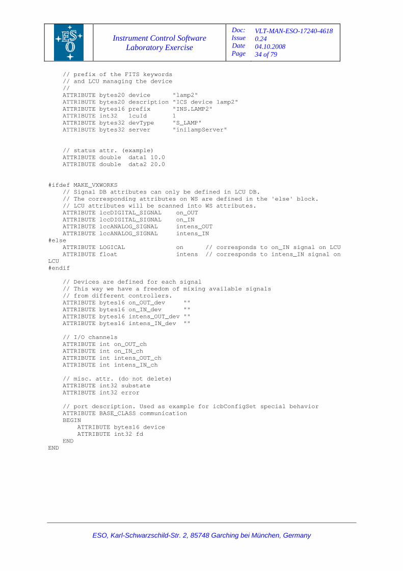
5.4.1 Device DB, file inilamp/dbl/inilampLAMP2.db: Database definition: POINT icbDEVICE_BASE :Appl_data:INSX:ICS:DEVICES:LAMP2 BEGIN ALIAS LAMP2 // name and desc. of the device,
Instrument Control Software Laboratory Exercise
Doc: Issue Date Page
VLT-MAN-ESO-17240-4618 0.24 04.10.2008 34 of 79
ESO, Karl-Schwarzschild-Str. 2, 85748 Garching bei München, Germany
// prefix of the FITS keywords // and LCU managing the device // ATTRIBUTE bytes20 device "lamp2" ATTRIBUTE bytes20 description "ICS device lamp2" ATTRIBUTE bytes16 prefix "INS.LAMP2" ATTRIBUTE int32 lcuId 1 ATTRIBUTE bytes32 devType "S_LAMP" ATTRIBUTE bytes32 server "inilampServer" // status attr. (example) ATTRIBUTE double data1 10.0 ATTRIBUTE double data2 20.0 #ifdef MAKE_VXWORKS // Signal DB attributes can only be defined in LCU DB. // The corresponding attributes on WS are defined in the 'else' block. // LCU attributes will be scanned into WS attributes. ATTRIBUTE lccDIGITAL_SIGNAL on_OUT ATTRIBUTE lccDIGITAL_SIGNAL on_IN ATTRIBUTE lccANALOG_SIGNAL intens_OUT ATTRIBUTE lccANALOG_SIGNAL intens_IN #else ATTRIBUTE LOGICAL on // corresponds to on_IN signal on LCU ATTRIBUTE float intens // corresponds to intens_IN signal on LCU #endif // Devices are defined for each signal // This way we have a freedom of mixing available signals // from different controllers. ATTRIBUTE bytes16 on_OUT_dev "" ATTRIBUTE bytes16 on_IN_dev "" ATTRIBUTE bytes16 intens_OUT_dev "" ATTRIBUTE bytes16 intens_IN_dev "" // I/O channels ATTRIBUTE int on_OUT_ch ATTRIBUTE int on_IN_ch ATTRIBUTE int intens_OUT_ch ATTRIBUTE int intens_IN_ch // misc. attr. (do not delete) ATTRIBUTE int32 substate ATTRIBUTE int32 error // port description. Used as example for icbConfigSet special behavior ATTRIBUTE BASE_CLASS communication BEGIN ATTRIBUTE bytes16 device ATTRIBUTE int32 fd END END
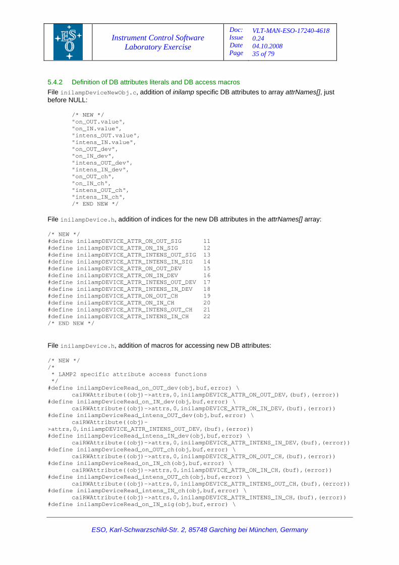
Instrument Control Software Laboratory Exercise
Doc: Issue Date Page
VLT-MAN-ESO-17240-4618 0.24 04.10.2008 35 of 79
ESO, Karl-Schwarzschild-Str. 2, 85748 Garching bei München, Germany
5.4.2 Definition of DB attributes literals and DB access macros File inilampDeviceNewObj.c, addition of inilamp specific DB attributes to array attrNames[], just before NULL: /* NEW */ "on_OUT.value", "on_IN.value", "intens_OUT.value", "intens_IN.value", "on_OUT_dev", "on_IN_dev", "intens_OUT_dev", "intens_IN_dev", "on_OUT_ch", "on_IN_ch", "intens_OUT_ch", "intens_IN_ch", /* END NEW */ File inilampDevice.h, addition of indices for the new DB attributes in the attrNames[] array: /* NEW */ #define inilampDEVICE_ATTR_ON_OUT_SIG 11 #define inilampDEVICE_ATTR_ON_IN_SIG 12 #define inilampDEVICE_ATTR_INTENS_OUT_SIG 13 #define inilampDEVICE_ATTR_INTENS_IN_SIG 14 #define inilampDEVICE_ATTR_ON_OUT_DEV 15 #define inilampDEVICE_ATTR_ON_IN_DEV 16 #define inilampDEVICE_ATTR_INTENS_OUT_DEV 17 #define inilampDEVICE_ATTR_INTENS_IN_DEV 18 #define inilampDEVICE_ATTR_ON_OUT_CH 19 #define inilampDEVICE_ATTR_ON_IN_CH 20 #define inilampDEVICE_ATTR_INTENS_OUT_CH 21 #define inilampDEVICE_ATTR_INTENS_IN_CH 22 /* END NEW */ File inilampDevice.h, addition of macros for accessing new DB attributes: /* NEW */ /* * LAMP2 specific attribute access functions */ #define inilampDeviceRead_on_OUT_dev(obj,buf,error) \ caiRWAttribute((obj)->attrs,0,inilampDEVICE_ATTR_ON_OUT_DEV,(buf),(error)) #define inilampDeviceRead_on_IN_dev(obj,buf,error) \ caiRWAttribute((obj)->attrs,0,inilampDEVICE_ATTR_ON_IN_DEV,(buf),(error)) #define inilampDeviceRead_intens_OUT_dev(obj,buf,error) \ caiRWAttribute((obj)->attrs,0,inilampDEVICE_ATTR_INTENS_OUT_DEV,(buf),(error)) #define inilampDeviceRead_intens_IN_dev(obj,buf,error) \ caiRWAttribute((obj)->attrs,0,inilampDEVICE_ATTR_INTENS_IN_DEV,(buf),(error)) #define inilampDeviceRead_on_OUT_ch(obj,buf,error) \ caiRWAttribute((obj)->attrs,0,inilampDEVICE_ATTR_ON_OUT_CH,(buf),(error)) #define inilampDeviceRead_on_IN_ch(obj,buf,error) \ caiRWAttribute((obj)->attrs,0,inilampDEVICE_ATTR_ON_IN_CH,(buf),(error)) #define inilampDeviceRead_intens_OUT_ch(obj,buf,error) \ caiRWAttribute((obj)->attrs,0,inilampDEVICE_ATTR_INTENS_OUT_CH,(buf),(error)) #define inilampDeviceRead_intens_IN_ch(obj,buf,error) \ caiRWAttribute((obj)->attrs,0,inilampDEVICE_ATTR_INTENS_IN_CH,(buf),(error)) #define inilampDeviceRead_on_IN_sig(obj,buf,error) \
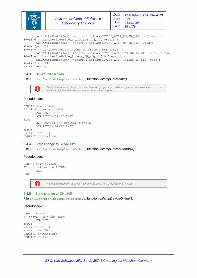
Instrument Control Software Laboratory Exercise
Doc: Issue Date Page
VLT-MAN-ESO-17240-4618 0.24 04.10.2008 36 of 79
caiRWAttribute((obj)->attrs,0,inilampDEVICE_ATTR_ON_IN_SIG,(buf),(error)) #define inilampDeviceWrite_on_IN_sig(obj,buf,error) \ caiRWAttribute((obj)->attrs,1,inilampDEVICE_ATTR_ON_IN_SIG,(void*) (buf),(error)) #define inilampDeviceRead_intens_IN_sig(obj,buf,error) \ caiRWAttribute((obj)->attrs,0,inilampDEVICE_ATTR_INTENS_IN_SIG,(buf),(error)) #define inilampDeviceWrite_intens_IN_sig(obj,buf,error) \ caiRWAttribute((obj)->attrs,1,inilampDEVICE_ATTR_INTENS_IN_SIG,(void*) (buf),(error)) /* END NEW */
5.4.3 Device Initialization File inilamp/src/inilampDeviceCmds.c, function inilampDeviceInit().
The initialization code is not optimized on purpose in order to give explicit examples of how to initialize digital and analog signals as inputs and outputs.
Pseudocode: DBREAD simulation IF simulation = T THEN LOG SWSIM = T LOG ACTION LAMP2 INIT ELSE INIT Analog and Digital signals LOG ACTION LAMP2 INIT ENDIF initialised = T DBWRITE initialised
5.4.4 State change to STANDBY File inilamp/src/inilampDeviceCmds.c, function inilampDeviceStandby(). Pseudocode: DBREAD initialised IF initialised != T THEN INIT ENDIF
We could switch the lamp OFF when changing from ONLINE to STANDBY.
5.4.5 State change to ONLINE File inilamp/src/inilampDeviceCmds.c, function inilampDeviceOnline(). Pseudocode: DBREAD state IF state < STANDBY THEN STANDBY ENDIF initialised = T state = ONLINE DBWRITE initialised DBWRITE state
ESO, Karl-Schwarzschild-Str. 2, 85748 Garching bei München, Germany
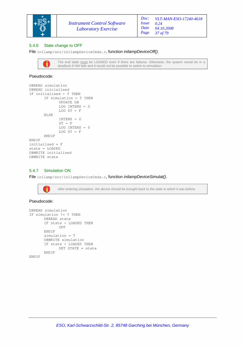
Instrument Control Software Laboratory Exercise
Doc: Issue Date Page
VLT-MAN-ESO-17240-4618 0.24 04.10.2008 37 of 79
5.4.6 State change to OFF File inilamp/src/inilampDeviceCmds.c, function inilampDeviceOff().
The end state must be LOADED even if there are failures. Otherwise, the system would be in a deadlock if HW fails and it would not be possible to switch to simulation.
Pseudocode: DBREAD simulation DBREAD initialised IF initialised = T THEN IF simulation = T THEN UPDATE DB LOG INTENS = 0 LOG ST = F ELSE INTENS = 0 ST = F LOG INTENS = 0 LOG ST = F ENDIF ENDIF initialised = F state = LOADED DBWRITE initialised DBWRITE state
5.4.7 Simulation ON File inilamp/src/inilampDeviceCmds.c, function inilampDeviceSimulat().
After entering simulation, the device should be brought back to the state in which it was before.
Pseudocode: DBREAD simulation IF simulation != T THEN DBREAD state IF state > LOADED THEN OFF ENDIF simulation = T DBWRITE simulation IF state > LOADED THEN SET STATE = state ENDIF ENDIF
ESO, Karl-Schwarzschild-Str. 2, 85748 Garching bei München, Germany
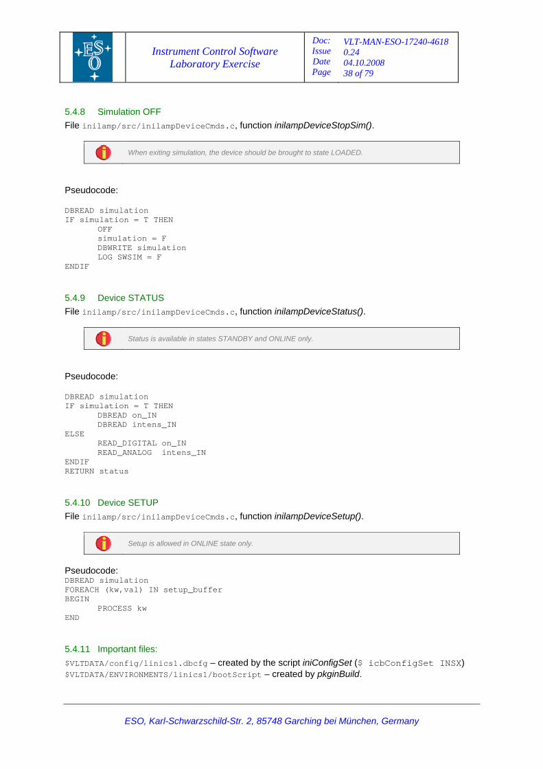
Instrument Control Software Laboratory Exercise
Doc: Issue Date Page
VLT-MAN-ESO-17240-4618 0.24 04.10.2008 38 of 79
5.4.8 Simulation OFF File inilamp/src/inilampDeviceCmds.c, function inilampDeviceStopSim().
When exiting simulation, the device should be brought to state LOADED.
Pseudocode: DBREAD simulation IF simulation = T THEN OFF simulation = F DBWRITE simulation LOG SWSIM = F ENDIF
5.4.9 Device STATUS File inilamp/src/inilampDeviceCmds.c, function inilampDeviceStatus().
Status is available in states STANDBY and ONLINE only.
Pseudocode: DBREAD simulation IF simulation = T THEN DBREAD on_IN DBREAD intens_IN ELSE READ_DIGITAL on_IN READ_ANALOG intens_IN ENDIF RETURN status
5.4.10 Device SETUP File inilamp/src/inilampDeviceCmds.c, function inilampDeviceSetup().
Setup is allowed in ONLINE state only.
Pseudocode: DBREAD simulation FOREACH (kw,val) IN setup_buffer BEGIN PROCESS kw END
5.4.11 Important files: $VLTDATA/config/linics1.dbcfg – created by the script iniConfigSet ($ icbConfigSet INSX) $VLTDATA/ENVIRONMENTS/linics1/bootScript – created by pkginBuild.
ESO, Karl-Schwarzschild-Str. 2, 85748 Garching bei München, Germany
Instrument Control Software Laboratory Exercise
Doc: Issue Date Page
VLT-MAN-ESO-17240-4618 0.24 04.10.2008 39 of 79
5.5 Creating WS Lamp Special Device The purpose is to implement an assembly class taking care of turning On/Off the LCU Special Lamp device and setting the intensity value using only one setup keyword. This will show how to use the ICB assemblies for more complex requirements which cannot be fulfilled using just the assembly configuration keywords. Lamp Power: 0 – 100% Lamp Intensity: 0 - 10 [V] The WS class will convert the power to the right intensity value.
Steps:
1. Stop the ICS processes if they are already running (as user insx) > ininsStop –proc ICS
2. Create the Lamp Class Declaration file (“iniLAMP_POWER.h”)
a. Rename file “iniINS_TRAK.h”
> cd ~/INSXSource/ICS/ini/include > mv iniINS_TRAK.h iniLAMP_POWER.h > tooReplace iniINS_TRAK iniLAMP_POWER *
xxiINS_TRAK is an example of especial assembly class provided with the Template Instrument.
b. Review the contents of the new file. It should look like the following:
#ifndef iniLAMP_POWER_H #define iniLAMP_POWER_H /* VLT file header excluded on purpose */
#ifndef __cplusplus #error This is a C++ include file and cannot be used from plain C #endif /* * System Headers */ /* * VLT Headers */ #include <fndDICTIONARY.h> #include "ic0INS_ASSEMBLY.h" // parent class
// Lamp device class iniLAMP_POWER: public ic0INS_ASSEMBLY { public: iniLAMP_POWER(); fndStdObjectDef(iniLAMP_POWER, ic0INS_ASSEMBLY) protected: virtual ccsCOMPL_STAT DevTrigger(ic0KEYWORD &keyword, void*);
ESO, Karl-Schwarzschild-Str. 2, 85748 Garching bei München, Germany
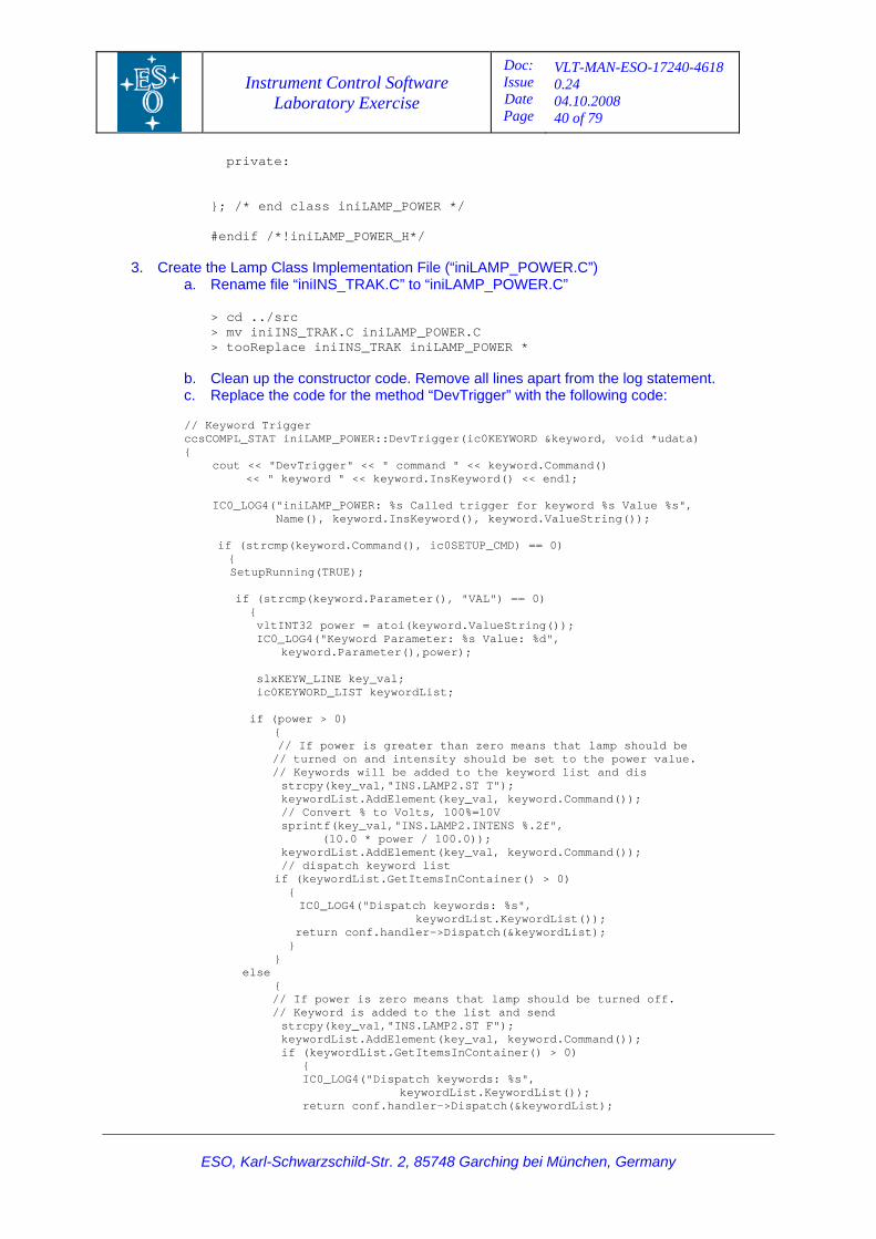
Instrument Control Software Laboratory Exercise
Doc: Issue Date Page
VLT-MAN-ESO-17240-4618 0.24 04.10.2008 40 of 79
ESO, Karl-Schwarzschild-Str. 2, 85748 Garching bei München, Germany
private: }; /* end class iniLAMP_POWER */ #endif /*!iniLAMP_POWER_H*/
3. Create the Lamp Class Implementation File (“iniLAMP_POWER.C”) a. Rename file “iniINS_TRAK.C” to “iniLAMP_POWER.C”
> cd ../src > mv iniINS_TRAK.C iniLAMP_POWER.C > tooReplace iniINS_TRAK iniLAMP_POWER *
b. Clean up the constructor code. Remove all lines apart from the log statement. c. Replace the code for the method “DevTrigger” with the following code:
// Keyword Trigger ccsCOMPL_STAT iniLAMP_POWER::DevTrigger(ic0KEYWORD &keyword, void *udata) { cout << "DevTrigger" << " command " << keyword.Command() << " keyword " << keyword.InsKeyword() << endl; IC0_LOG4("iniLAMP_POWER: %s Called trigger for keyword %s Value %s", Name(), keyword.InsKeyword(), keyword.ValueString());
if (strcmp(keyword.Command(), ic0SETUP_CMD) == 0) { SetupRunning(TRUE); if (strcmp(keyword.Parameter(), "VAL") == 0) { vltINT32 power = atoi(keyword.ValueString()); IC0_LOG4("Keyword Parameter: %s Value: %d", keyword.Parameter(),power); slxKEYW_LINE key_val; ic0KEYWORD_LIST keywordList; if (power > 0) { // If power is greater than zero means that lamp should be // turned on and intensity should be set to the power value. // Keywords will be added to the keyword list and dis strcpy(key_val,"INS.LAMP2.ST T"); keywordList.AddElement(key_val, keyword.Command()); // Convert % to Volts, 100%=10V sprintf(key_val,"INS.LAMP2.INTENS %.2f", (10.0 * power / 100.0)); keywordList.AddElement(key_val, keyword.Command()); // dispatch keyword list if (keywordList.GetItemsInContainer() > 0) {
IC0_LOG4("Dispatch keywords: %s", keywordList.KeywordList());
return conf.handler->Dispatch(&keywordList); } } else { // If power is zero means that lamp should be turned off. // Keyword is added to the list and send strcpy(key_val,"INS.LAMP2.ST F"); keywordList.AddElement(key_val, keyword.Command()); if (keywordList.GetItemsInContainer() > 0) { IC0_LOG4("Dispatch keywords: %s", keywordList.KeywordList()); return conf.handler->Dispatch(&keywordList);
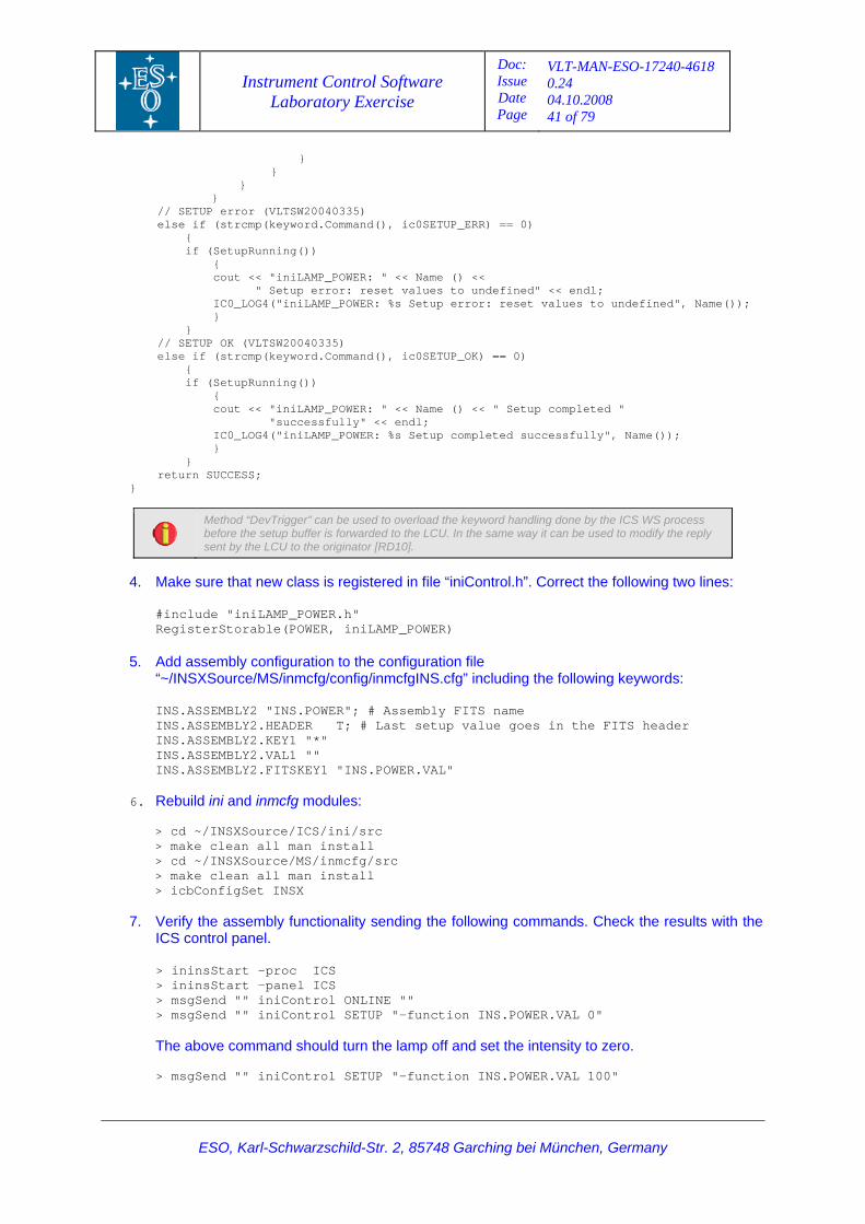
Instrument Control Software Laboratory Exercise
Doc: Issue Date Page
VLT-MAN-ESO-17240-4618 0.24 04.10.2008 41 of 79
} } } } // SETUP error (VLTSW20040335) else if (strcmp(keyword.Command(), ic0SETUP_ERR) == 0) { if (SetupRunning()) { cout << "iniLAMP_POWER: " << Name () << " Setup error: reset values to undefined" << endl; IC0_LOG4("iniLAMP_POWER: %s Setup error: reset values to undefined", Name()); } } // SETUP OK (VLTSW20040335) else if (strcmp(keyword.Command(), ic0SETUP_OK) == 0) { if (SetupRunning()) { cout << "iniLAMP_POWER: " << Name () << " Setup completed " "successfully" << endl; IC0_LOG4("iniLAMP_POWER: %s Setup completed successfully", Name()); } } return SUCCESS; }
Method “DevTrigger” can be used to overload the keyword handling done by the ICS WS process before the setup buffer is forwarded to the LCU. In the same way it can be used to modify the reply sent by the LCU to the originator [RD10].
4. Make sure that new class is registered in file “iniControl.h”. Correct the following two lines:
#include "iniLAMP_POWER.h" RegisterStorable(POWER, iniLAMP_POWER)
5. Add assembly configuration to the configuration file “~/INSXSource/MS/inmcfg/config/inmcfgINS.cfg” including the following keywords: INS.ASSEMBLY2 "INS.POWER"; # Assembly FITS name INS.ASSEMBLY2.HEADER T; # Last setup value goes in the FITS header INS.ASSEMBLY2.KEY1 "*" INS.ASSEMBLY2.VAL1 "" INS.ASSEMBLY2.FITSKEY1 "INS.POWER.VAL"
6. Rebuild ini and inmcfg modules: > cd ~/INSXSource/ICS/ini/src > make clean all man install > cd ~/INSXSource/MS/inmcfg/src > make clean all man install > icbConfigSet INSX
7. Verify the assembly functionality sending the following commands. Check the results with the
ICS control panel.
> ininsStart –proc ICS > ininsStart –panel ICS > msgSend "" iniControl ONLINE "" > msgSend "" iniControl SETUP "-function INS.POWER.VAL 0" The above command should turn the lamp off and set the intensity to zero. > msgSend "" iniControl SETUP "-function INS.POWER.VAL 100"
ESO, Karl-Schwarzschild-Str. 2, 85748 Garching bei München, Germany
Instrument Control Software Laboratory Exercise
Doc: Issue Date Page
VLT-MAN-ESO-17240-4618 0.24 04.10.2008 42 of 79
ESO, Karl-Schwarzschild-Str. 2, 85748 Garching bei München, Germany
The above command should turn the lamp on and set the intensity to its maximum power.
5.6 Session Summary In this session we learned how to create special devices at LCU and WS levels and how to incorporate them into the existing instrument. It was also explained the need for special devices and their advantages and disadvantages compared with the existing standard devices supported by the VLTSW. The code represents a very simple example which can be used as a sample code for more complex applications for real instruments.
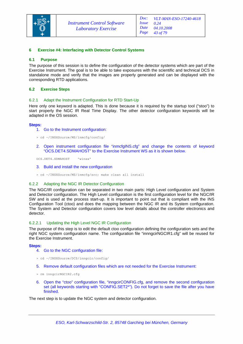
Instrument Control Software Laboratory Exercise
Doc: Issue Date Page
VLT-MAN-ESO-17240-4618 0.24 04.10.2008 43 of 79
ESO, Karl-Schwarzschild-Str. 2, 85748 Garching bei München, Germany
6 Exercise #4: Interfacing with Detector Control Systems
6.1
6.2
Purpose The purpose of this session is to define the configuration of the detector systems which are part of the Exercise Instrument. The goal is to be able to take exposures with the scientific and technical DCS in standalone mode and verify that the images are properly generated and can be displayed with the corresponding RTD applications.
Exercise Steps
6.2.1 Adapt the Instrument Configuration for RTD Start-Up Here only one keyword is adapted. This is done because it is required by the startup tool (“stoo”) to start properly the NGC IR Real Time Display. The other detector configuration keywords will be adapted in the OS session. Steps:
1. Go to the Instrument configuration: > cd ~/INSXSource/MS/inmcfg/config/
2. Open instrument configuration file “inmcfgINS.cfg” and change the contents of keyword
“OCS.DET4.SDMAHOST” to the Exercise Instrument WS as it is shown below. OCS.DET4.SDMAHOST "winsx" 3. Build and install the new configuration > cd ~/INSXSource/MS/inmcfg/src; make clean all install
6.2.2 Adapting the NGC IR Detector Configuration The NGC/IR configuration can be separated in two main parts: High Level configuration and System and Detector configuration. The High Level configuration is the first configuration level for the NGC/IR SW and is used at the process start-up. It is important to point out that is compliant with the INS Configuration Tool (ctoo) and does the mapping between the NGC IR and its System configuration. The System and Detector configuration covers low level details about the controller electronics and detector.
6.2.2.1 Updating the High Level NGC IR Configuration The purpose of this step is to edit the default ctoo configuration defining the configuration sets and the right NGC system configuration name. The configuration file “innngcirNGCIR1.cfg” will be reused for the Exercise Instrument.
Steps: 4. Go to the NGC configuration file: > cd ~/INSXSource/DCS/inngcir/config/ 5. Remove default configuration files which are not needed for the Exercise Instrument: > rm inngcirNGCIR2.cfg 6. Open the “ctoo” configuration file, “inngcirCONFIG.cfg, and remove the second configuration
set (all keywords starting with “CONFIG.SET2*”). Do not forget to save the file after you have finished.
The next step is to update the NGC system and detector configuration.
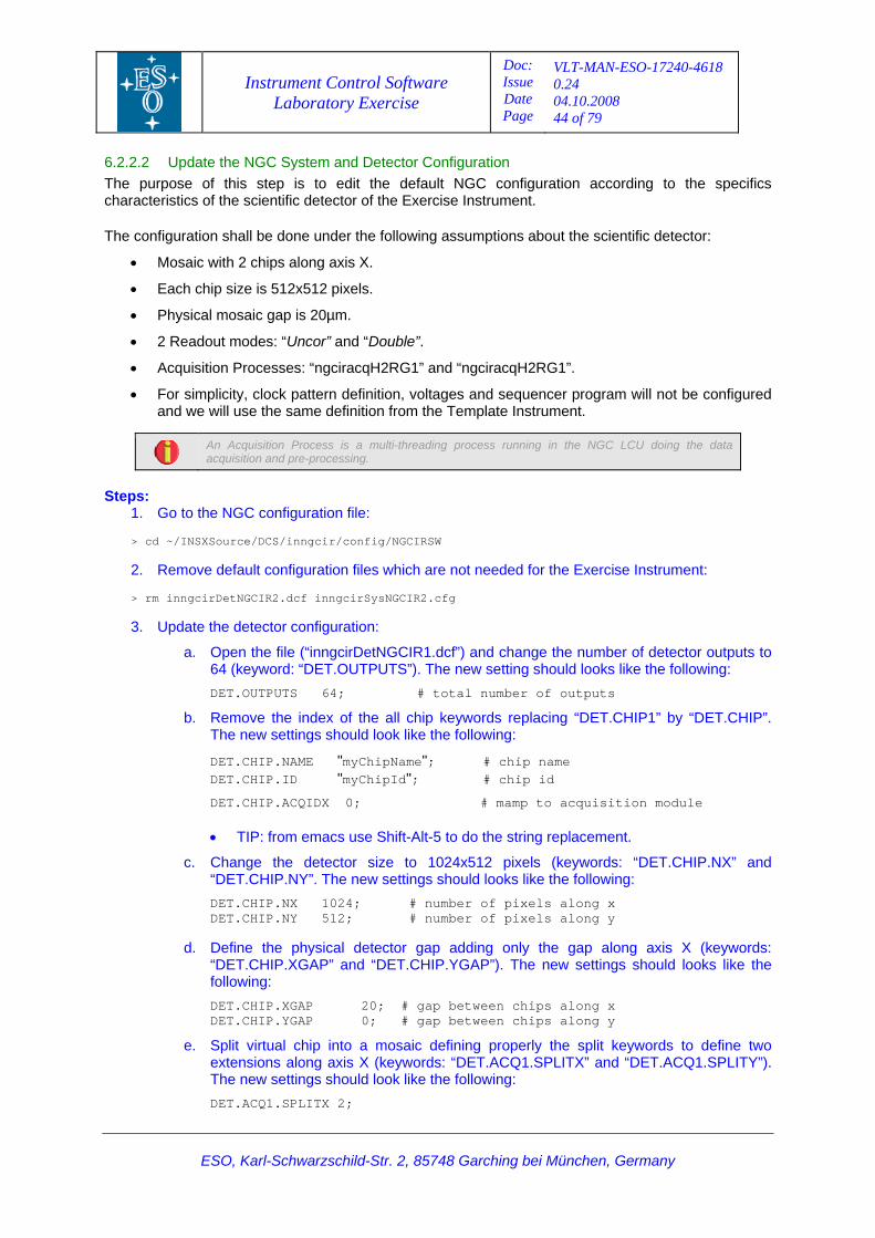
Instrument Control Software Laboratory Exercise
Doc: Issue Date Page
VLT-MAN-ESO-17240-4618 0.24 04.10.2008 44 of 79
6.2.2.2 Update the NGC System and Detector Configuration The purpose of this step is to edit the default NGC configuration according to the specifics characteristics of the scientific detector of the Exercise Instrument. The configuration shall be done under the following assumptions about the scientific detector:
• Mosaic with 2 chips along axis X.
• Each chip size is 512x512 pixels.
• Physical mosaic gap is 20µm.
• 2 Readout modes: “Uncor” and “Double”.
• Acquisition Processes: “ngciracqH2RG1” and “ngciracqH2RG1”.
• For simplicity, clock pattern definition, voltages and sequencer program will not be configured and we will use the same definition from the Template Instrument.
An Acquisition Process is a multi-threading process running in the NGC LCU doing the data acquisition and pre-processing.
Steps: 1. Go to the NGC configuration file: > cd ~/INSXSource/DCS/inngcir/config/NGCIRSW 2. Remove default configuration files which are not needed for the Exercise Instrument: > rm inngcirDetNGCIR2.dcf inngcirSysNGCIR2.cfg 3. Update the detector configuration:
a. Open the file (“inngcirDetNGCIR1.dcf”) and change the number of detector outputs to 64 (keyword: “DET.OUTPUTS”). The new setting should looks like the following:
DET.OUTPUTS 64; # total number of outputs
b. Remove the index of the all chip keywords replacing “DET.CHIP1” by “DET.CHIP”. The new settings should look like the following:
DET.CHIP.NAME "myChipName"; # chip name DET.CHIP.ID "myChipId"; # chip id
DET.CHIP.ACQIDX 0; # mamp to acquisition module • TIP: from emacs use Shift-Alt-5 to do the string replacement.
c. Change the detector size to 1024x512 pixels (keywords: “DET.CHIP.NX” and “DET.CHIP.NY”. The new settings should looks like the following:
DET.CHIP.NX 1024; # number of pixels along x DET.CHIP.NY 512; # number of pixels along y
d. Define the physical detector gap adding only the gap along axis X (keywords:
“DET.CHIP.XGAP” and “DET.CHIP.YGAP”). The new settings should looks like the following:
DET.CHIP.XGAP 20; # gap between chips along x DET.CHIP.YGAP 0; # gap between chips along y
e. Split virtual chip into a mosaic defining properly the split keywords to define two extensions along axis X (keywords: “DET.ACQ1.SPLITX” and “DET.ACQ1.SPLITY”). The new settings should look like the following:
DET.ACQ1.SPLITX 2;
ESO, Karl-Schwarzschild-Str. 2, 85748 Garching bei München, Germany
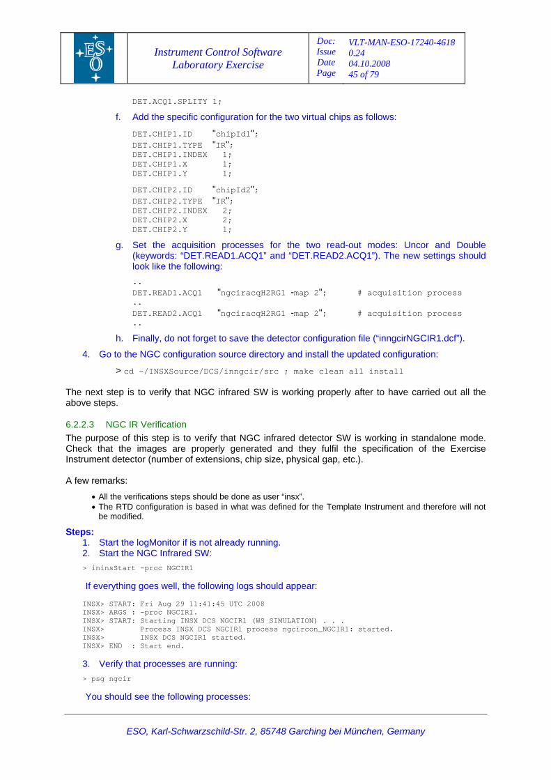
Instrument Control Software Laboratory Exercise
Doc: Issue Date Page
VLT-MAN-ESO-17240-4618 0.24 04.10.2008 45 of 79
ESO, Karl-Schwarzschild-Str. 2, 85748 Garching bei München, Germany
DET.ACQ1.SPLITY 1;
f. Add the specific configuration for the two virtual chips as follows:
DET.CHIP1.ID "chipId1"; DET.CHIP1.TYPE "IR"; DET.CHIP1.INDEX 1; DET.CHIP1.X 1; DET.CHIP1.Y 1;
DET.CHIP2.ID "chipId2"; DET.CHIP2.TYPE "IR"; DET.CHIP2.INDEX 2; DET.CHIP2.X 2; DET.CHIP2.Y 1;
g. Set the acquisition processes for the two read-out modes: Uncor and Double (keywords: “DET.READ1.ACQ1” and “DET.READ2.ACQ1”). The new settings should look like the following:
.. DET.READ1.ACQ1 "ngciracqH2RG1 -map 2"; # acquisition process .. DET.READ2.ACQ1 "ngciracqH2RG1 -map 2"; # acquisition process ..
h. Finally, do not forget to save the detector configuration file (“inngcirNGCIR1.dcf”).
4. Go to the NGC configuration source directory and install the updated configuration:
> cd ~/INSXSource/DCS/inngcir/src ; make clean all install The next step is to verify that NGC infrared SW is working properly after to have carried out all the above steps.
6.2.2.3 NGC IR Verification The purpose of this step is to verify that NGC infrared detector SW is working in standalone mode. Check that the images are properly generated and they fulfil the specification of the Exercise Instrument detector (number of extensions, chip size, physical gap, etc.). A few remarks:
• All the verifications steps should be done as user “insx”. • The RTD configuration is based in what was defined for the Template Instrument and therefore will not
be modified.
Steps: 1. Start the logMonitor if is not already running. 2. Start the NGC Infrared SW: > ininsStart -proc NGCIR1 If everything goes well, the following logs should appear: INSX> START: Fri Aug 29 11:41:45 UTC 2008 INSX> ARGS : -proc NGCIR1. INSX> START: Starting INSX DCS NGCIR1 (WS SIMULATION) . . . INSX> Process INSX DCS NGCIR1 process ngcircon_NGCIR1: started. INSX> INSX DCS NGCIR1 started. INSX> END : Start end. 3. Verify that processes are running: > psg ngcir You should see the following processes:
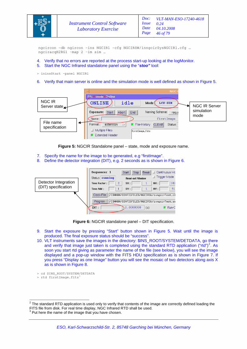
Instrument Control Software Laboratory Exercise
Doc: Issue Date Page
VLT-MAN-ESO-17240-4618 0.24 04.10.2008 46 of 79
ngcircon –db ngircon –ins NGCIR1 –cfg NGCIRSW/inngcirSysNGCIR1.cfg … ngciracqH2RG1 –map 2 –im sim …
4. Verify that no errors are reported at the process start-up looking at the logMonitor. 5. Start the NGC Infrared standalone panel using the “stoo” tool: > ininsStart -panel NGCIR1 6. Verify that main server is online and the simulation mode is well defined as shown in Figure 5.
NGC IR Server state NGC IR Server
simulation mode
File name specification
Figure 5: NGCIR Standalone panel – state, mode and exposure name.
7. Specify the name for the image to be generated, e.g “firstImage”. 8. Define the detector integration (DIT), e.g. 2 seconds as is shown in Figure 6.
Detector Integration (DIT) specification
Figure 6: NGCIR standalone panel – DIT specification.
9. Start the exposure by pressing “Start” button shown in Figure 5. Wait until the image is produced. The final exposure status should be “success”.
10. VLT instruments save the images in the directory: $INS_ROOT/SYSTEM/DETDATA, go there and verify that image just taken is completed using the standard RTD application (“rtd”)2. As soon you start rtd giving as parameter the name of the file (see below), you will see the image displayed and a pop-up window with the FITS HDU specification as is shown in Figure 7. If you press “Display as one Image” button you will see the mosaic of two detectors along axis X as is shown in Figure 8.
> cd $INS_ROOT/SYSTEM/DETDATA > rtd firstImage.fits3
2 The standard RTD application is used only to verify that contents of the image are correctly defined loading the FITS file from disk. For real time display, NGC Infrared RTD shall be used. 3 Put here the name of the image that you have chosen.
ESO, Karl-Schwarzschild-Str. 2, 85748 Garching bei München, Germany
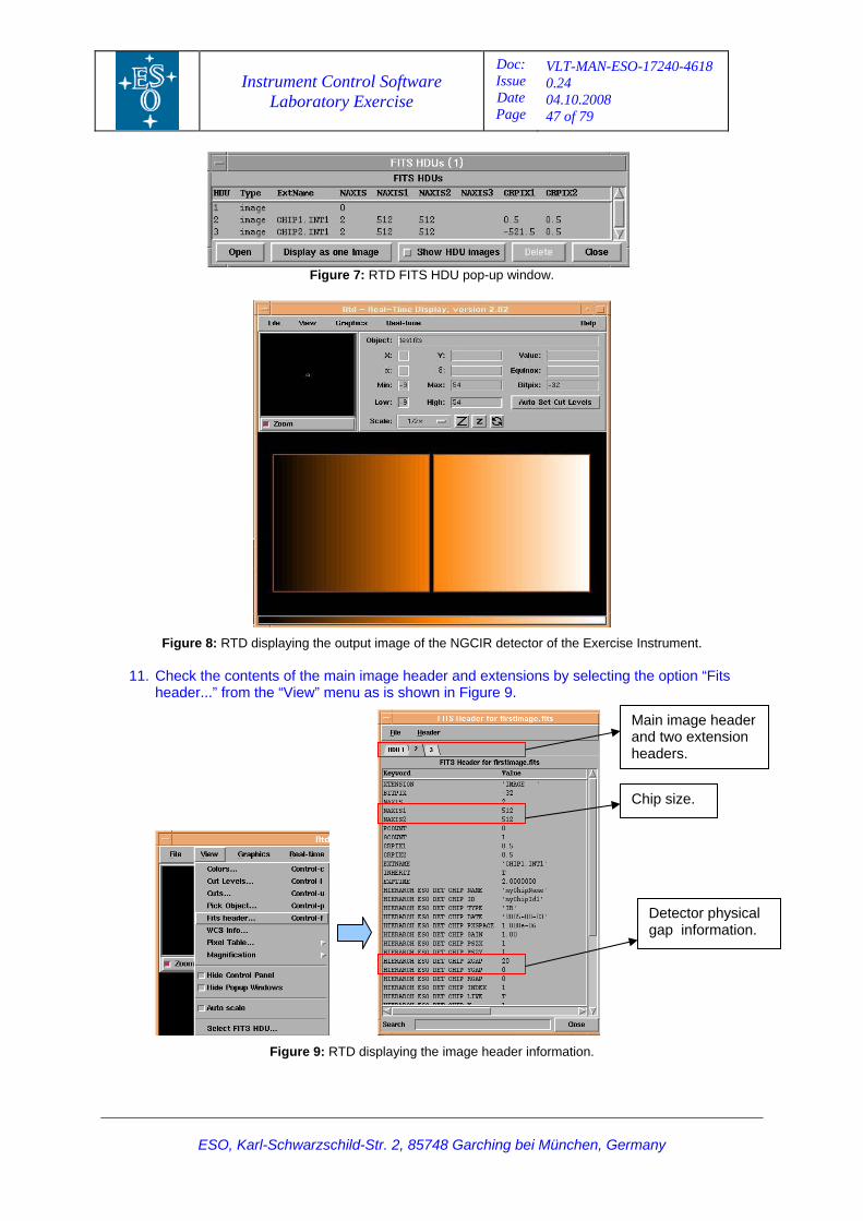
Instrument Control Software Laboratory Exercise
Doc: Issue Date Page
VLT-MAN-ESO-17240-4618 0.24 04.10.2008 47 of 79
Figure 7: RTD FITS HDU pop-up window.
Figure 8: RTD displaying the output image of the NGCIR detector of the Exercise Instrument.
11. Check the contents of the main image header and extensions by selecting the option “Fits header...” from the “View” menu as is shown in Figure 9.
Detector physical gap information.
Chip size.
Main image header and two extension headers.
Figure 9: RTD displaying the image header information.
ESO, Karl-Schwarzschild-Str. 2, 85748 Garching bei München, Germany
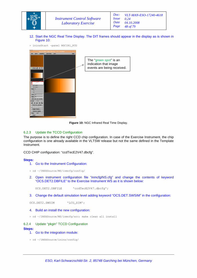
Instrument Control Software Laboratory Exercise
Doc: Issue Date Page
VLT-MAN-ESO-17240-4618 0.24 04.10.2008 48 of 79
ESO, Karl-Schwarzschild-Str. 2, 85748 Garching bei München, Germany
lay. The DIT frames should appear in the display as is shown in
> ininsStart -panel NGCIR1_RTD
12. Start the NGC Real Time DispFigure 10:
The “green spot” is an indication that image events are being received.
NGC Infrared Real Time Display.
is to define the right CCD chip configuration. In case of the Exercise Instrument, the chip onfiguration is one already available in the VLTSW release but not the same defined in the Template
IP configuration: “ccdTecE2V47.dbcfg”.
Steps:
2. pen instrument configuration file “inmcfgINS.cfg” and change the contents of keyword as it is shown below:
adding keyword “OCS.DET.SWSIM” in the configuration:
clean all install
ration teps:
Figure 10:
6.2.3 Update the TCCD Configuration The purposecInstrument. CCD CH
1. Go to the Instrument Configuration:
> cd ~/INSXSource/MS/inmcfg/config/
O“OCS.DET2.DBFILE” to the Exercise Instrument WS OCS.DET2.DBFILE "ccdTecE2V47.dbcfg";
3. Change the default simulation level
OCS.DET2.SWSIM "LCU_SIM";
4. Build an install the new configuration: > cd ~/INSXSource/MS/inmcfg/src; make
6.2.4 Update “pkgin” TCCD ConfiguS
1. Go to the integration module:
> cd ~/INSXSource/inins/config/
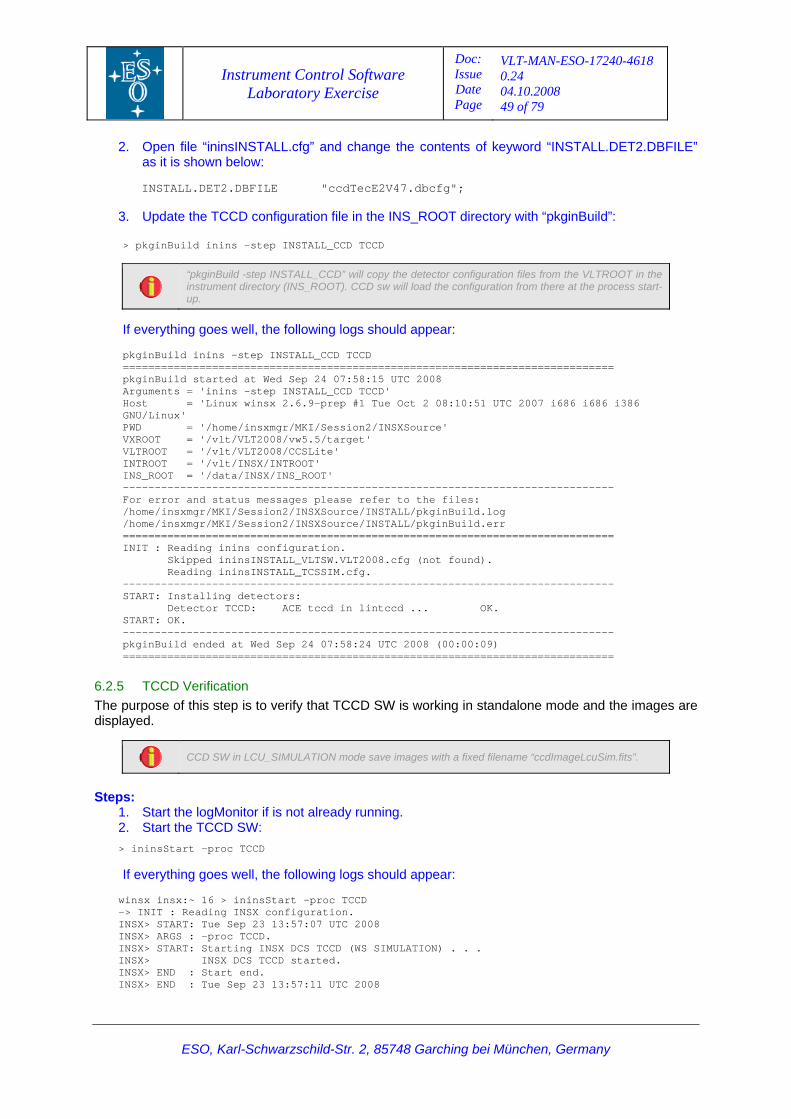
Instrument Control Software Laboratory Exercise
Doc: Issue Date Page
VLT-MAN-ESO-17240-4618 0.24 04.10.2008 49 of 79
ESO, Karl-Schwarzschild-Str. 2, 85748 Garching bei München, Germany
2. pen file “ininsINSTALL.cfg” and change the contents of keyword “INSTALL.DET2.DBFILE”
47.dbcfg";
3. Update
> pkginBuild inins -step INSTALL_CCD TCCD
Oas it is shown below:
INSTALL.DET2.DBFILE "ccdTecE2V
the TCCD configuration file in the INS_ROOT directory with “pkginBuild”:
“pkginBuild -step INSTALL_CCD” will copy the detector configuration files from the VLTROOT in the instrument directory (INS_ROOT). CCD sw will load the configuration from there at the process start-
up.
d appearIf everything goes well, the following logs shoul :
========================
' #1 Tue Oct 2 08:10:51 UTC 2007 i686 i686 i386
------------------------------------------------------
6.2.5 TCCD Verification The purpos of ages are
isplayed.
pkginBuild inins -step INSTALL_CCD TCCD =====================================================
5 UTC 2008 pkginBuild started at Wed Sep 24 07:58:1D TCCDArguments = 'inins -step INSTALL_CC
rep Host = 'Linux winsx 2.6.9-pGNU/Linux' PWD = '/home/insxmgr/MKI/Session2/INSXSource' VXROOT = '/vlt/VLT2008/vw5.5/target' VLTROOT = '/vlt/VLT2008/CCSLite' INTROOT = '/vlt/INSX/INTROOT' INS_ROOT = '/data/INSX/INS_ROOT'
----------------------------------------- ------------------------------------For error and status messages please refer to the files:
STALL/pkginBuild.log/home/insxmgr/MKI/Session2/INSXSource/IN/home/insxmgr/MKI/Session2/INSXSource/INSTALL/pkginBuild.err
================================================ =============================INIT : Reading inins configuration.
ped ininsINSTALL_VLTSW.VLT2008.cfg (not found). Skip Reading ininsINSTALL_TCSSIM.cfg.
----------------- ------------------------------------------------------------START: Installing detectors: Detector TCCD: ACE tccd in lintccd ... OK. START: OK. -----------------------pkginBuild ended at Wed Sep 24 07:58:24 UTC 2008 (00:00:09) =============================================================================
e this step is to verify that TCCD SW is working in standalone mode and the im
d
CCD SW in LCU_SIMULATION mode save images with a fixed filename “ccdImageLcuSim.fits”.
Ste
uld appear:
(WS SIMULATION) . . .
: Start end. : Tue Sep 23 13:57:11 UTC 2008
ps1
: . Start the logMonitor if is not already running. . Start the TCCD SW: 2
> ininsStart -proc TCCD
following logs shoIf everything goes well, the
CCD winsx insx:~ 16 > ininsStart -proc Tonfiguration.-> INIT : Reading INSX c
INSX> START: Tue Sep 23 13:57:07 UTC 2008 NSX> ARGS : -proc TCCD. I
INSX> START: Starting INSX DCS TCCD NSX> INSX DCS TCCD started. I
INSX> END NSX> END I
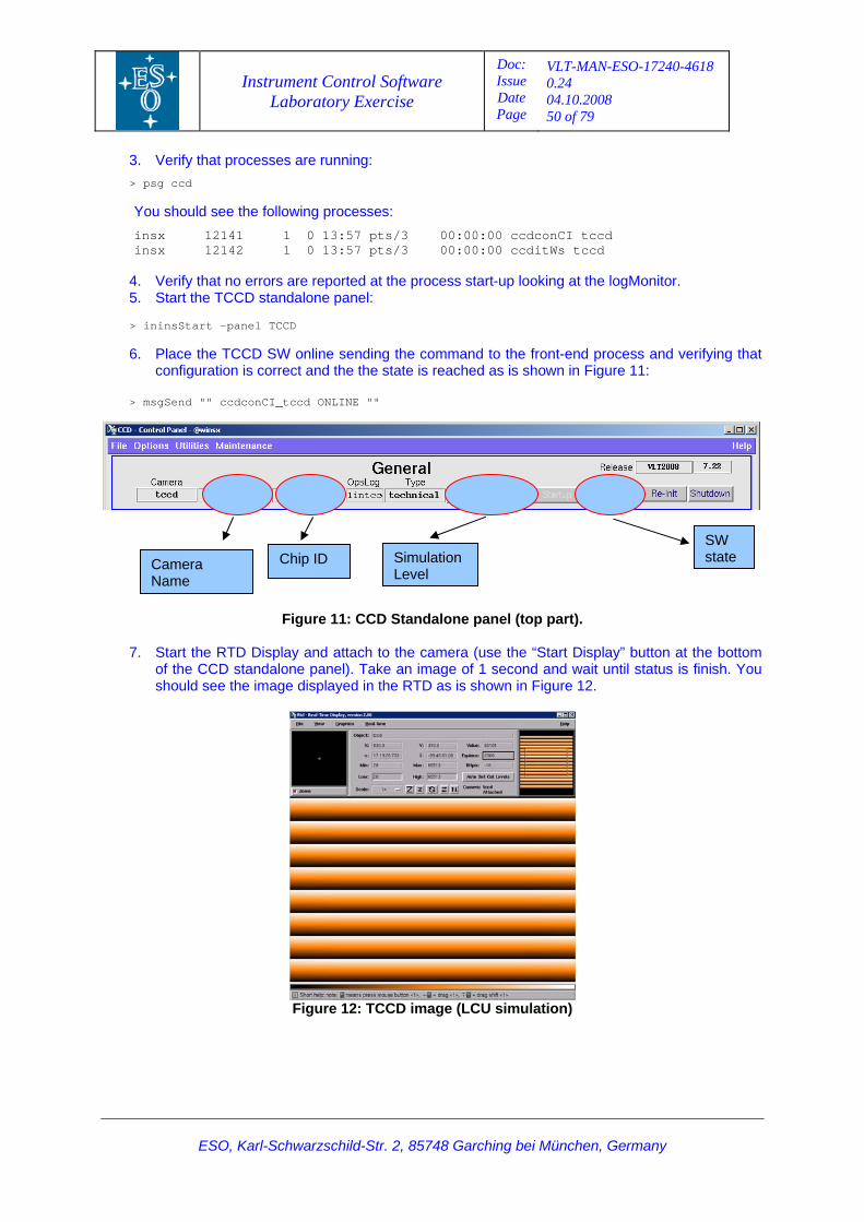
Instrument Control Software Laboratory Exercise
Doc: Issue Date Page
VLT-MAN-ESO-17240-4618 0.24 04.10.2008 50 of 79
ESO, Karl-Schwarzschild-Str. 2, 85748 Garching bei München, Germany
3 >
s/3 00:00:00 ccdconCI tccd 0 13:57 pts/3 00:00:00 ccditWs tccd
Place the TCCD SW online sending the command to the front-end process and verifying that configuration is correct and the the state is reached as is shown in Figure 11:
. Verify that processes are running: psg ccd
You should see the following processes:
nsxi 12141 1 0 13:57 ptinsx 12142 1
4. Verify that no errors are reported at the process start-up looking at the logMonitor. 5. Start the TCCD standalone panel:
> ininsStart -panel TCCD 6.
> msgSend "" ccdconCI_tccd ONLINE ""
7. Start the RTD Display and attach to the camera (use the “Start Display” button at the bottom
of the CCD standalone panel). Take an image of 1 second and wait until status is finish. You should see the image displayed in the RTD as is shown in Figure 12.
Figure 11: CCD Standalone panel (top part).
Figure 12: TCCD image (LCU simulation)
Camera Name
Chip ID Simulation SW state
Level
Instrument Control Software Laboratory Exercise
Doc: Issue Date Page
VLT-MAN-ESO-17240-4618 0.24 04.10.2008 51 of 79
ESO, Karl-Schwarzschild-Str. 2, 85748 Garching bei München, Germany
6.3 Session Summary tector systems for the Exercise Instrument and their
verification in standalone mode. The course participant should have experienced the process to ent configuration files associated with the NGC infrared and technical CCD SW.
This session involved the configuration of the de
prepare the differ
Instrument Control Software Laboratory Exercise
Doc: Issue Date Page
VLT-MAN-ESO-17240-4618 0.24 04.10.2008 52 of 79
ESO, Karl-Schwarzschild-Str. 2, 85748 Garching bei München, Germany
7 Ex S
7.1 PThe pu ms and the supported observation modes
7.2 ImThe obs
• • ns.
ercise #5: Observation Software – O
urpose all the OS subsysterpose of this session is to configure
of the Exercise Instrument.
plementation Details re the followings: ervation modes foreseen for the fictitious instrument a
IMAGING: Direct imaging using the two detectors. CALIBRATION: Special mode for the technical detector intended for calibratio
The behaviour of OS is defined via configuration keywords. This covers all the basic information about the each subsystem that will be coordinated by the OS [RD11] . OS configuration keywords have the following format: OCS.<CAT>.i.NAME. Where <CAT> can be one of the following categories: DET, INS, OS and TEL [RD11]
7.3 E
Steps: 1. to the Instrument configuration
/config
2. 3. t name (keyword “OCS.TEL.ENVNAME”) as is shown
4. from the OS part of the instrument configuration i.e.
1”. These keywords are left over from the Template ot part of the Exercise
tem from the OS configuration. i.e. all keywords starting with
remaining detector subsystems. Changing all keywords starting from CS.DET4” to “OCS.DET1” (belonging to NGCIR1).
After step 4 - 6 the OS detector configuration should looks like the following:
--------------------------------------------------------------- OCS.DET1.NAME "NGCIR1";
xercise Steps
7.3.1 Configure OS Subsystems
Go
d ~/INSXSource/MS/inmcfg> c
Open the configuration file “inmcfgINS.cfg”.
Update the telescope environmenbelow:
OCS.TEL.ENVNAME “wintcs”;
Remove the IRACE (IRDCS) subsystemall keywords starting with “OCS.DETInstrument. They are intended for an IRACE system which is nInstrument.
5. Remove the FIERA subsys“OCS.DET3”.
6. Update the index of the
“O
# Subsystem: DET1 - NGCIR1 # -----------
OCS.DET1.DICT "NGCDCS"; T1.ENVNAME "winsx"; OCS.DE
OCS.DET1.PROCNAME "inircon_NGCIR1";
Instrument Control Software Laboratory Exercise
Doc: Issue Date Page
VLT-MAN-ESO-17240-4618 0.24 04.10.2008 53 of 79
ESO, Karl-Schwarzschild-Str. 2, 85748 Garching bei München, Germany
# Subsystem: DET2 TCCD -----------------------------------------
OCS.DET2.NAME "TCCD"; "CCDDCS";
T "DET2.*.*.*.*.*.*,DET.*.*.*.*.*.*"; 20;
cd"; OCS.DET2.TYPE "ACE"; OCS.DET2.CCDNAME "tccd";
7. r of detectors systems accordingly (keyword “OCS.DET.NUM”):
OCS.DET.NUM 2;
8. Update the observation modes according to the request for the Exercise Instrument (keyword “OCS.MODEi”). The final setting should looks like the following: # # 5.5 Instrument modes # OCS.MODE1.NAME "CALIBRATION"; OCS.MODE1.SETUP "-function INS.MIRR1.NAME In"; OCS.MODE1.SUBSYST "TCCD ICS UT1"; OCS.MODE1.PATH "TCCD"; OCS.MODE2.NAME "IMAGING"; OCS.MODE2.SETUP "-function INS.MIRR1.NAME Out"; OCS.MODE2.SUBSYST "NGCIR1 TCCD ICS UT1"; OCS.MODE2.PATH "INFRARED";
9. Build and Install the module “inmcfg”:
> cd ~/INSXSource/MS/inmcfg/src; make clean all install
1. Go to the OS module:
the subsystem list in the main OS server database class (file “dbl/inoSERVER.class”)
ATTRIBUTE bossINTERFACE_TCCD tccd
OCS.DET1.KEYWFILT "DET1.*.*.*.*.*.*"; OCS.DET1.TIMEOUT 20; OCS.DET1.TYPE "NGCIR";
ET1.CFGSET "NGCIR1"; OCS.DOCS.DET1.DBROOT "<alias>ngcircon_NGCIR1"; OCS.DET1.SDMAHOST "winsx" OCS.DET1.RTDPORT "7001"
# -------------------------------
OCS.DET2.DICT1 OCS.DET2.ENVNAME "winsx"; OCS.DET2.PROCNAME "ccdconCI_tccd"; OCS.DET2.KEYWFILOCS.DET2.TIMEOUTOCS.DET2.DBROOT "<alias>tc
OCS.DET2.CCDLENV "lintccd"; OCS.DET2.DBFILE "ccdTecE2V47.dbcfg"; OCS.DET2.SWSIM “LCU-SIM”;
Update the numbe
7.3.2 OS Database Configuration Steps:
> cd ~/INSXSource/OS/ino/
2. Updateand remove the detector subsystems which are not used. Final configuration should be as isshown below:
CLASS bossINTERFACE_LIST inodbSUB_SYSTEMS BEGIN
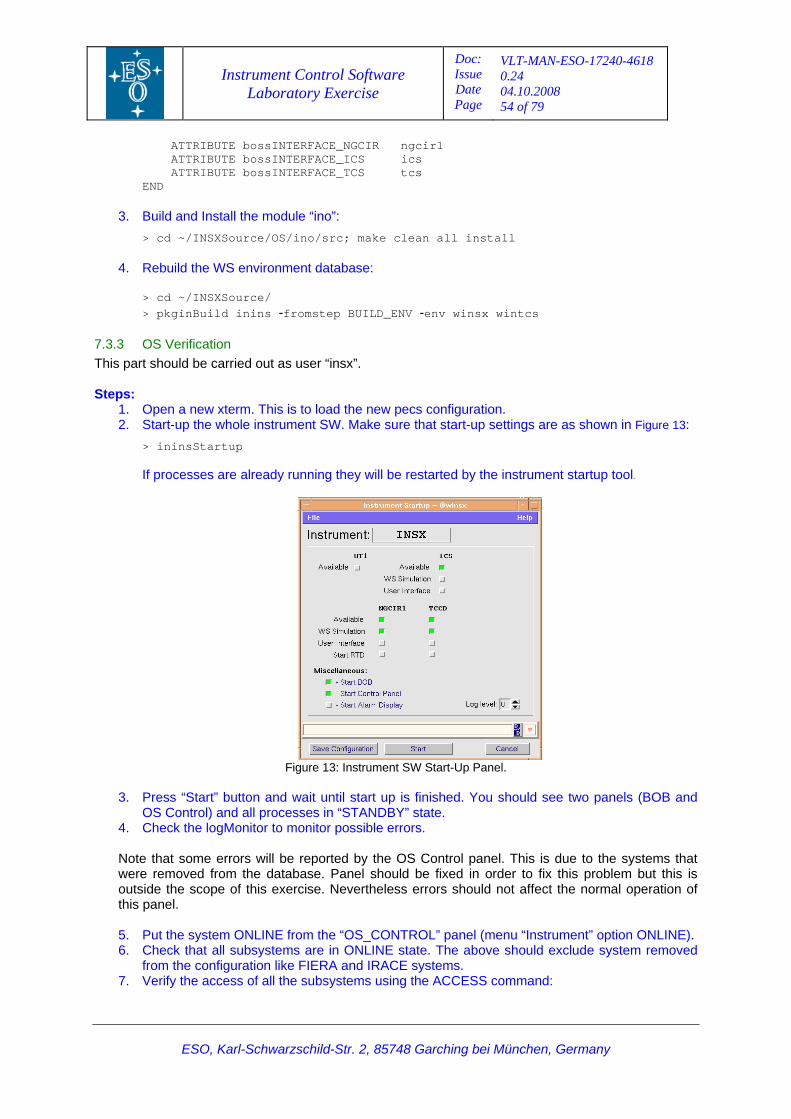
Instrument Control Software Laboratory Exercise
Doc: Issue Date Page
VLT-MAN-ESO-17240-4618 0.24 04.10.2008 54 of 79
ESO, Karl-Schwarzschild-Str. 2, 85748 Garching bei München, Germany
ir1
s
3. module “ino”:
/src; make clean all install
4. database:
fromstep BUILD_ENV env winsx wintcs
7.3.3 This pa
1. pen a new xterm. This is to load the new pecs configuration. 2. shown in Figure 13:
processes are already running they will be restarted by the instrument startup tool.
ATTRIBUTE bossINTERFACE_NGCIR ngc ATTRIBUTE bossINTERFACE_ICS ics
ATTRIBUTE bossINTERFACE_TCS tcEND
Build and Install the> cd ~/INSXSource/OS/ino
Rebuild the WS environment
> cd ~/INSXSource/ > pkginBuild inins - -
OS Verification ould be carried out as user “insx”. rt sh
Steps:
OStart-up the whole instrument SW. Make sure that start-up settings are as
> ininsStartup If
Figure 13: Instrument SW Start-Up Panel.
3 rt” button and wait until start up is finished. You should see two panels (BOB and d all processes in “STANDBY” state.
4. Check the logMonitor to monitor possible errors.
Note that some errors will be reported by the OS Control panel. This is due to the systems that were removed from the database. Panel sho d be fixed in order to fix this problem but this is
al operation of this panel.
5. _CONTROL” panel (menu “Instrument” option ONLINE).
7. Verify the access of all the subsystems using the ACCESS command:
. Press “Sta
OS Control) an
uloutside the scope of this exercise. Nevertheless errors should not affect the norm
Put the system ONLINE from the “OS
6. Check that all subsystems are in ONLINE state. The above should exclude system removed from the configuration like FIERA and IRACE systems.
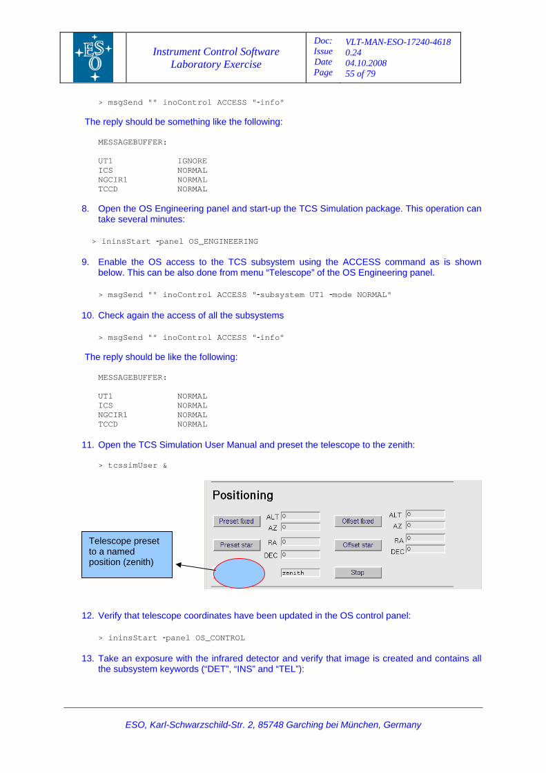
Instrument Control Software Laboratory Exercise
Doc: Issue Date Page
VLT-MAN-ESO-17240-4618 0.24 04.10.2008 55 of 79
ESO, Karl-Schwarzschild-Str. 2, 85748 Garching bei München, Germany
Th
UT1 IGNORE NORMAL
8. and start-up the TCS Simulation package. This operation can
> ininsStart -panel OS_ENGINEERING
9. Enable the OS access to the TCS subsystem using the ACCESS command as is shown below. This can be also done from menu “Telescope” of the OS Engineering panel. > msgSend "" inoControl ACCESS "-subsystem UT1 -mode NORMAL"
10. Check again the access of all the subsystems
> msgSend "" inoControl ACCESS "-info"
The reply should be like the following:
MESSAGEBUFFER: UT1 NORMAL ICS NORMAL NGCIR1 NORMAL TCCD NORMAL
11. Open the TCS Simulation User Manual and preset the telescope to the zenith:
> tcssimUser &
> msgSend "" inoControl ACCESS "-info"
e reply should be something like the following:
MESSAGEBUFFER:
ICS NGCIR1 NORMAL
NORMAL TCCD
pen the OS Engineering panelOtake several minutes:
12. Verify that telescope coordinates have been updated in the OS control panel:
> ininsStart -panel OS_CONTROL
13. Take an exposure with the infrared detector and verify that image is created and contains all the subsystem keywords (“DET”, “INS” and “TEL”):
Telescope preset to a named position (zenith)
Instrument Control Software Laboratory Exercise
Doc: Issue Date Page
VLT-MAN-ESO-17240-4618 0.24 04.10.2008 56 of 79
ESO, Karl-Schwarzschild-Str. 2, 85748 Garching bei München, Germany
> msgSend "" inoControl SETUP "-expoId 0 -function INS.MODE IMAGING tFile"
> msgSend "" inoControl START "-detId NGCIR1" nd "" inoControl WAIT ""
M/DETDATA
OCS.DET.IMGNAME myFirs
> msgSe
The reply should be like the following:
MESSAGEBUFFER: Observation status: INTEGRATING MESSAGEBUFFER: Exposure status: FINISHED
> cd $INS_ROOT/SYSTE> slxCatFits myFirstFile<day of year>_<number>.fits
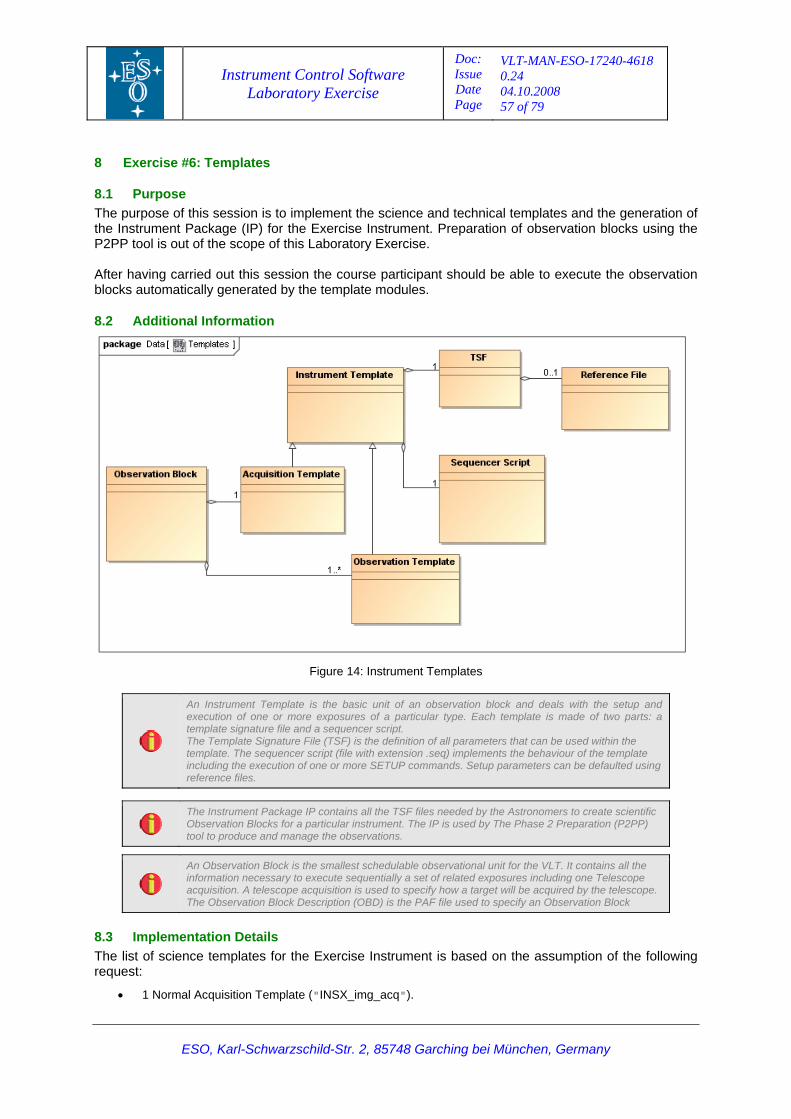
Instrument Control Software Laboratory Exercise
Doc: Issue Date Page
VLT-MAN-ESO-17240-4618 0.24 04.10.2008 57 of 79
8 Exercise #6: Templates
ESO, Karl-Schwarzschild-Str. 2, 85748 Garching bei München, Germany
se of this session is to implement the science and technical templates and the generation of nstrument. Preparation of observation blocks using the
P2PP tool is out of the scope of this Laboratory Exercise.
is session the course participant should be able to execute the observation les.
8.1 Purpose he purpoT
the Instrument Package (IP) for the Exercise I
After having carried out thblocks automatically generated by the template modu
8.2 Additional Information
Figure 14: Instrument Templates
An Instrument Template is the basic unit of an observation block and deals with the setup and execution of one or more exposures of a particular type. Each template is made of two parts: a template signature file and a sequencer script. The Template Signature File (TSF) is the definition of all parameters that can be used within the template. The sequencer script (file with extension .se q) implements the behaviour of the template including the execution of one or more SETUP commands. Setup parameters can be defaulted using reference files.
The Instrument Package IP contains all the TSF files needed by the Astronomers to create scientific
Observation Blocks for a particular instrument. The IP is used by The Phase 2 Preparation (P2PP) tool to produce and manage the observations.
An Observation Block is the smallest schedulable observational unit for the VLT. It contains all the information necessary to execute sequentially a set of related exposures including one Telescope acquisition. A telescope acquisition is used to specify how a target will be acquired by the telescope. The Observation Block Description (OBD) is the PAF file used to specify an Observation Block
8.3 ImpleThe list of scien ssumption of the following request:
• 1 Normal Acquisition Template ("INSX_img_acq").
me tation Details nce templates for the Exercise Instrument is based on the a
Instrument Control Software Laboratory Exercise
Doc: Issue Date Page
VLT-MAN-ESO-17240-4618 0.24 04.10.2008 58 of 79
ESO, Karl-Schwarzschild-Str. 2, 85748 Garching bei München, Germany
• 1 Observ• 1 Observation Template for the Imaging Mode using jittering ( INSX_img_obs_AutoJitter").
The list of te ption of the following request:
• 1 Bias T
8.4 Exercise
8.4.1 Prepa eSteps:
1. Go to th
> cd ~/
2. Rem e
> rm sr INSX_irimg_obs*
b. for the Exercise Instrument (keyword:
racteristics of the Exercise wing:
J Y"
f.
ation Template for the Imaging Mode ("INSX_img_obs_exp"). "
chnical templates for the Exercise Instrument is based on the assum
emplate ("INSX_gen_tec_bias").
Steps
r science TSF Files (module “inotsf”)
e scientific TSF module:
INSXSource/OS/inotsf/
ov unnecessary files:
c/INSX_opt* src/INSX*spec* src/
3. Update the Instrument Summary File (ISF): a. Open file “config/INSX.isf”
Update observation modes to the ones defined“MODES”). This should looks like the following:
MODES "IMAGING CALIBRATION"
c. Delete all the lines below comment “OTHER TAGS”. d. Update the CCD window size to the detector cha
Instrument (keyword "CCD.WINDOW"). The setting should looks like the follo
CCD.WINDOW "1 1 1024 512"
e. Add the setting for the filters and default parameter values:
FILTERS "H IR.NDIT.RANGE "1 1000" INS.FILT1.NAME.VALUE "H" ET1.DIT.TEST.VALUE "1" DDET2.UIT.TEST.VALUE "5"
Finally, do not forget to save the file “config/INSX.isf”.
The Instrument Summary File (ISF) contains a summary of the instrument elements which are addressable from the observation preparation tool (P2PP).
A template is the basic unit of an Observation Block.
XSource/OS/inotsf/src/
s:
irimg_acq img_acq INSX_img_acq.tsfx
d. cq_MoveToSlit.tsfx” to follow the naming
4. Adapt the Acquisition Template Signature File:
a. Go to the sources > cd ~/INS
n for templateb. Rename file “INSX_irimg_acq.tsfx” to follow the naming conventio
> mv INSX_irimg_acq.tsfx INSX_img_acq.tsfx
c. Rename all instances of “irimg_acq” to “img_acq” inside the file:
> tooReplace
Rename file “INSX_ngcirimg_a
Instrument Control Software Laboratory Exercise
Doc: Issue Date Page
VLT-MAN-ESO-17240-4618 0.24 04.10.2008 59 of 79
ESO, Karl-Schwarzschild-Str. 2, 85748 Garching bei München, Germany
Slit.tsfx INSX_img_acq_MoveToSlit.tsfx
f.
ooReplace DET4 DET1 inotsfNGCIR_DET_DIT.tsfx
g. e associated reference setup file and P” and “TPL.PRESEQ”). The new setting
ile
i. following:
j. the associated reference
file ncer script
l. llowing:
.INCLUDE "inotsfNGCIR_DET.tsfx";
> mv INSX_ngcirimg_acq_MoveTo
e. ename all instances of “irimg_acq” to “img_acq” inside the file: R
ce ngcirimg_acq img_acq INSX_img_acq_MoveToSlit.tsfx > tooRepla
etector index in the include file: Adapt d
cd ~/INSXSource/OS/inotsf/include > t>
Open the file “INSX_img_acq.tsfx” and change ththe sequence script (keywords “TPL.REFSUshould looks like the following:
TPL.REFSUP "INSX_img_acq.ref"; # Reference setup fTPL.PRESEQ "INSX_img_acq.seq"; # Sequencer script
h. Change the instrument mode (keyword “INS.MODE.VALUE”) as is shown below:
INS.MODE.VALUE "IMAGING"
Add the telescope conditional preset keyword by including file “inotsfSEQ_PRESET.tsfx”. The include entries should looks like the
PAF.INCLUDE "inotsfTEL.tsfx" .INCLUDE "inotsfSEQ_PRESET.tsfx" PAF
Open the file “INSX_img_acq_MoveToSlit.tsfx” and change
PL.REFSUP” and “TPL.PRESEQ”). setup file and the sequence script (keywords “TThe new setting should looks like the following:
TPL.REFSUP "INSX_img_acq.ref"; # Reference setup TPL.PRESEQ "INSX_img_acq_MoveToSlit.seq"; # Seque
k. Change the default TPL mode (keyword “TPL.MODE”) as is shown below:
TPL.MODE "IMAGING"
scope conditional preset keyword by including file Add the tele“inotsfSEQ_PRESET.tsfx”. The include entries should looks like the fo
PAF.INCLUDE "inotsfTEL.tsfx"; F.INCLUDE "inotsfSEQ_ACQ.tsfx"; PA
AFPPAF.INCLUDE "inotsfSEQ_PRESET.tsfx";
The “SEQ.PRESET” is a keyword used to prevent the telescope preset. This is used to save time when the acquisition template must be repeated and the telescope is already in position. T
he default
value is always true and can only be modified by the Instrument Operator.
a.
x
b. irimg_obs_exp img_obs_exp INSX_img_obs_exp.tsfx
c. DE” to “IMAGING” as is
5. Adapt the Observation Template Signature File
Rename file “INSX_ngcirimg_obs_exp.tsfx” to follow the naming convention for templates:
NSX_ngcirimg_obs_exp.tsfx INSX_img_obs_exp.tsf> mv I
Rename all instances of “irimg_acq” to “img_acq” inside the file:
> tooReplace ngc
Open file “INSX_img_obs.exp.tsfx” and setup the set “TPL.MOshown below:
TPL.MODE "IMAGING"
Instrument Control Software Laboratory Exercise
Doc: Issue Date Page
VLT-MAN-ESO-17240-4618 0.24 04.10.2008 60 of 79
ESO, Karl-Schwarzschild-Str. 2, 85748 Garching bei München, Germany
6. Add an ation (Optional):
a. OFFSET.tsfx” with the following contents: ****************************
--------------------------------------
box"; "Number of offsets within a box";
rd SEQ.JITTER.WIDTH
------------------------
ANGE "5..60"; DEFAULT "NODEFAULT"; LABEL "Jitter Box Width (arcsec)"; .MINIHELP "Jitter Box Width (arcsec)";
ontents:
# NAME on Index of Dispersion
# ----------------------------------------
"SEQ.POISSON.IDIS"; TYPE "integer";
S.LABEL "Poisson index of dispersion"; oisson index of dispersion";
ntents: **********************
maging with jitter
----------------------
";
AutoJitter observ
Create the TSFX file “inotsfSEQ_N
#*****************************************# NAME # inotsfSEQ_NOFFSET - number of exposures # -------------------------------## TPL.PARAM "SEQ.NOFFSET"; SEQ.NOFFSET.TYPE "integer"; SEQ.NOFFSET.RANGE "1..1000"; SEQ.NOFFSET.DEFAULT "NODEFAULT"; EQ.NOFFSET.LABEL "Number of offsets within a SSEQ.NOFFSET.MINIHELP
b. Create the TSFX file “inotsfSEQ_JITTER_WIDTH.tsfx” with the following contents:
#********************************************************************* NAME ## inotsfSEQ_JITTER_WIDTH - keywo# #---------------------------------------------# TPL.PARAM "SEQ.JITTER.WIDTH"; SEQ.JITTER.WIDTH.TYPE "number"; SEQ.JITTER.WIDTH.RSEQ.JITTER.WIDTH.
H.SEQ.JITTER.WIDTEQ.JITTER.WIDTHS
. c Create the TSFX file “inotsfSEQ_POISSON_IDIS.tsfx” with the following c
#*********************************************************************
# hkotsfSEQ_POISSON_IDIS – Poiss
#-----------------------------# TPL.PARAM SEQ.POISSON.IDIS.SEQ.POISSON.IDIS.RANGE "1..100"; SEQ.POISSON.IDIS.DEFAULT "10"; SEQ.POISSON.IDISEQ.POISSON.IDIS.MINIHELP "PSEQ.POISSON.IDIS.HIDE "OHS";
h the following cod. Create the TSFX file “INSX_img_obs_AutoJitter.tsfx” wit
#***********************************************# NAME # INSX_img_obs_AutoJitter - I# #-----------------------------------------------# PAF.HDR.START; PAF.ID "$Id$" PAF.DESC "Imaging with jitter"; PAF.CRTE.NAME ""; PAF.CRTE.DAYTIM "PAF.LCHG.NAME ""; PAF.LCHG.DAYTIM "";
Instrument Control Software Laboratory Exercise
Doc: Issue Date Page
VLT-MAN-ESO-17240-4618 0.24 04.10.2008 61 of 79
ESO, Karl-Schwarzschild-Str. 2, 85748 Garching bei München, Germany
PAF.HDR.END;
otsfINS_FILT.tsfx";
otsfSEQ_JITTER_WIDTH.tsfx";
7. u a
ll' done"
ercise Instrument IP:
are reported and TSF files are generated in the config directory. :
installed in the INS_ROOT directory: MPLATES/TSF
1.
3. .seq
> mv INSX_ngcirimg_obs_exp.seq INSX_img_obs_exp.seq > mv INSX_ngcirimg_obs_exp.obdv INSX_img_obs_exp.obdv
oR> tooR> tooR
encer file. Open file “INSX_img_acq.seq” and cha ted. The ID of Cassagrain focus is “CA”. The new
6. 5 with file “INSX_img_acq_MoveToSlit.seq”.
TPL.INSTRUM "INSX"; TPL.MODE "IMAGING"; TPL.VERSION "$Revision: 1.16 $"; TPL.REFSUP "";
"; TPL.PRESEQ "INSX_img_obs_AutoJitter.seqTPL.TYPE "science"; PAF.INCLUDE "inotsfSEQ.tsfx"; PAF.INCLUDE "inotsfNGCIR_DET.tsfx"; PAF.INCLUDE "inPAF.INCLUDE "inotsfSEQ_NOFFSET.tsfx"; PAF.INCLUDE "inPAF.INCLUDE "inotsfSEQ_POISSON_IDIS.tsfx";
nd Install the TSF module: B ilda. Update the “Makefile” file removing the special setting in the make rule “all”. This
setting was only need for the Template Instrument. The rule should looks like the following:
all: do_all . 'a @echo " . .
b. Generate the TSF files and the Ex
>
c. Verify that no errorsd. Install the TSF files
> cd inotsf/src > make install
that files aree. Check
> cd $INS_ROOT/SYSTEM/COMMON/TE
8.4.2 Prepare the Sequencer Files (Module: “inoseq”) teps: S
Go to the scientific template script module:
> cd ~/INSXSource/OS/inoseq/src
2. Remove unnecessary files:
> rm INSX_irimg* INSX_optimg* INSX*spec* inoseqGenTecSelfTest.txt_with_midas
Rename sequencer files:
> mv INSX_acq.seq INSX_img_acq> mv INSX_ngcirimg_acq_MoveToSlit.seq INSX_img_acq_MoveToSlit.seq
4. Replace the names inside the file
s: > to eplace INSX_acq INSX_img_acq *
eplace INSX_ngcirimg_acq INSX_img_acq * lace INSX_ngcirimg_obs_exp INSX_img_obs_exp * ep
5. Update Telescope Focus ID in the acquisition sequnge the line where the “tplTCS” object is crea line should looks like the following:
tplTCS tcs TCS ino tcs CA INSX
Do the same as step
Instrument Control Software Laboratory Exercise
Doc: Issue Date Page
VLT-MAN-ESO-17240-4618 0.24 04.10.2008 62 of 79
ESO, Karl-Schwarzschild-Str. 2, 85748 Garching bei München, Germany
7. Update cer file. Open file
“INSX_ CIR” object is created. The index o e the following:
set dcsFullName [namespace current]::[tplNGCIR dcs ngcircon_NGCIR1 NGCIR1 1]
8. Do the
imaging observation template. Open file detector. New
setting shoul
DET1.SEQ.DIT "2";
the detector index in the imaging observation sequenimg_obs_exp.seq” and change the line where the “tplNGf the scientific detector is 1. The new line should looks lik
same as step 7 with file “INSX_img_acq_MoveToSlit.seq”.
9. Update the OBDV file for the “INSX_img_obs_exp.obdv” and update the integration time and the index of the
d be like the following:
The OBD Value files (OBDV) are used by the tool tpltooObdBuild to provide a way to overwrite the definition of the keyword v alues in the TSF at the generation of the test OBD files.
10. Create
contents of the new file sho
PAF.HDPAF.TYPAF.IDPAF.NAME "INSX_img_acq"; PAF.DEPAF.CRPAF.CRPAF.LCPAF.LCPAF.CHPAF.CHPAF.CHPAF.HD TEL.TATEL.TARG.DELTA "-850000.";
11. Copy th
> cp INSX_img_acq.obdv INSX_img_acq_MoveToSlit.obdv
12. Update acq_MoveToSlit.obdv” adding the default setting for the NGC de ”):
DET1.S
13. Update
a. emove
rm * c*
b. enam
c.
_exp *
d. rcise strum
a new OBDV file, “INSX_img_acq.obdv”, to overwrite the telescope coordinates. The uld looks like the following:
TART; R.SPE "Template";
Id$"; "$
SC "Imaging Acquisition"; TE.NAME "";
YTIM ""; TE.DAHG.NAME ""; HG.DAYTIM ""; CK.NAME ""; CK.DAYTIM "";
.CHECKSUM ""; CKR.END
RG.ALPHA "000000.";
e new OBDV file as “INSX_img_acq_MoveToSlit.obdv”:
th V file “INSX_img_e OBDtector integration time (keyword “DET1.SEQ.DIT
EQ.DIT "2";
reference files: R
unnecessary files: > cd ~/INSXSource/OS/inoseq/config > .obd INSX_optimg* INSX_*spe
R e reference files: > mv INSX_acq.ref INSX_img_acq.ref mv IN X_img_obs_exp.ref > SX_irimg_obs_exp.ref INS
s inside the files: Replace the name> tooReplace INSX_acq INSX_img_acq *
INSX_ngcirimg_obs_exp INSX_img_obs> tooReplace
Adapt the file “INSX_img_obs_exp.ref” according the functions of the ExeIn ent:
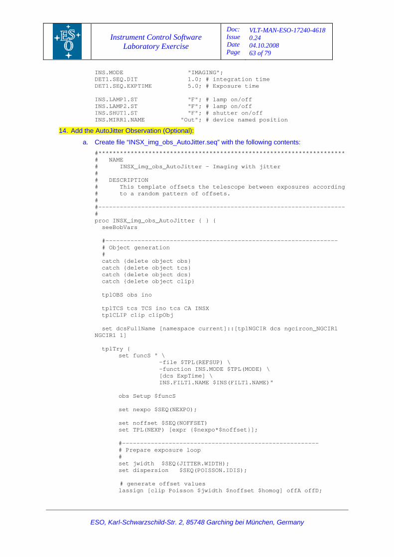
Instrument Control Software Laboratory Exercise
Doc: Issue Date Page
VLT-MAN-ESO-17240-4618 0.24 04.10.2008 63 of 79
ESO, Karl-Schwarzschild-Str. 2, 85748 Garching bei München, Germany
T1.S t e
"F"; # lamp on/off
S.MI t"; # device named position
INS.MODE "IMAGING"; DE EQ.DIT 1.0; # integration imDET1.SEQ.EXPTIME 5.0; # Exposure time INS.LAMP1.ST INS.LAMP2.ST "F"; # lamp on/off INS.SHUT1.ST "F"; # shutter on/off IN RR1.NAME "Ou
14. Add the :
a. tents: **** *****************
maging with jitter
ding
---- -----------------------------
oc I
#--- ----- -----------
catc object dcs} object clip}
A INSX tplCL
set s ngcircon_NGCIR1
L(REFSUP) \ -function INS.MODE $TPL(MODE) \ [dcs ExpTime] \
-------------------------------------- loop
ITTER.WIDTH); SEQ(POISSON.IDIS);
values [clip Poisson $jwidth $noffset $homog] offA offD;
A er Observation (Optional)utoJitt
Create file “INSX_img_obs_AutoJitter.seq” with the following con
#* ***********************************************# NAME # INSX_img_obs_AutoJitter - I# # DESCRIPTION
ures accor# This template offsets the telescope between expos# to a random pattern of offsets. # #- -----------------------------------#
g_obs_AutoJitter { } { pr NSX_im seeBobVars
------------ -- -------------------------------- # Object generation
# catch {delete object obs}
te object tcs} h {dele catch {delete
delete catch { tplOBS obs ino
tplT CS tcs TCS ino tcs CIP clip clipObj
dcsFullName [namespace current]::[tplNGCIR dcNGCIR1 1] tplTry { set funcS " \
-file $TP
INS.FILT1.NAME $INS(FILT1.NAME)"
o bs Setup $funcS set nexpo $SEQ(NEXPO); set noffset $SEQ(NOFFSET) set TPL(NEXP) [expr {$nexpo*$noffset}]; #----------------- # Prepare exposure # set jwidth $SEQ(J set dispersion $
ate offset # generlassign
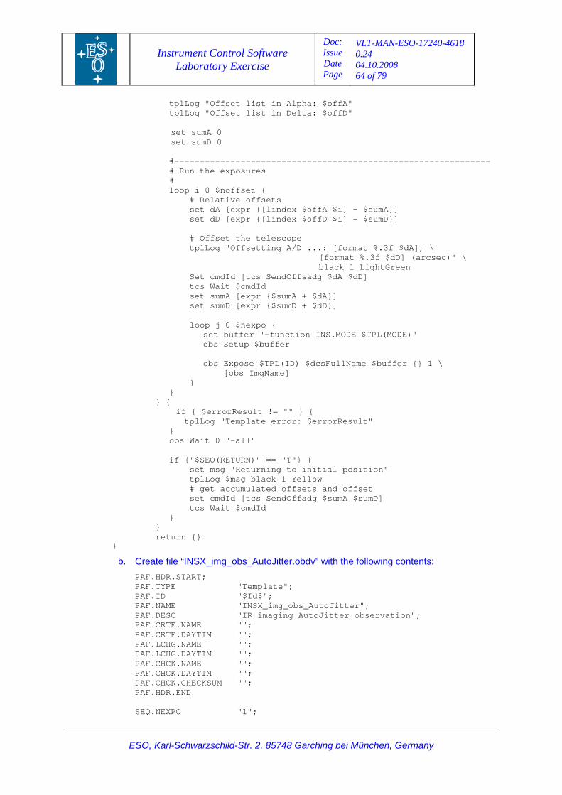
Instrument Control Software Laboratory Exercise
Doc: Issue Date Page
VLT-MAN-ESO-17240-4618 0.24 04.10.2008 64 of 79
ESO, Karl-Schwarzschild-Str. 2, 85748 Garching bei München, Germany
in Alpha: $offA" in Delta: $offD"
t { ffsets
dA [expr {[lindex $offA $i] - $sumA}] {[lindex $offD $i] - $sumD}]
]
$TPL(ID) $dcsFullName $buffer {} 1 \ Name]
# get accumulated offsets and offset set cmdId [tcs SendOffadg $sumA $sumD] tcs Wait $cmdId } } return {}
}
b. Create file “INSX_img_obs_AutoJitter.obdv” with the following contents:
PAF.HDR.START; PAF.TYPE "Template"; PAF.ID
PAF.CHCK.NAME ""; PAF.CHCK.DAYTIM ""; PAF.CHCK.CHECKSUM ""; PAF.HDR.END SEQ.NEXPO "1";
tplLog "Offset list tplLog "Offset list
set sumA 0 set sumD 0 #-------------------------------------------------------------- # Run the exposures # loop i 0 $noffse
lative o # Re set
set dD [expr # Offset the telescope tplLog "Offsetting A/D ...: [format %.3f $dA], \ [format %.3f $dD] (arcsec)" \ black 1 LightGreen Set cmdId [tcs SendOffsadg $dA $dD tcs Wait $cmdId set sumA [expr {$sumA + $dA}] set sumD [expr {$sumD + $dD}] loop j 0 $nexpo { set buffer "-function INS.MODE $TPL(MODE)" obs Setup $buffer obs Expose [obs Img } } } { if { $errorResult != "" } { tplLog "Template error: $errorResult" } obs Wait 0 "-all" if {"$SEQ(RETURN)" == "T"} { set msg "Returning to initial position" tplLog $msg black 1 Yellow
"$Id$"; PAF.NAME "INSX_img_obs_AutoJitter"; PAF.DESC "IR imaging AutoJitter observation"; PAF.CRTE.NAME ""; PAF.CRTE.DAYTIM ""; PAF.LCHG.NAME ""; PAF.LCHG.DAYTIM "";
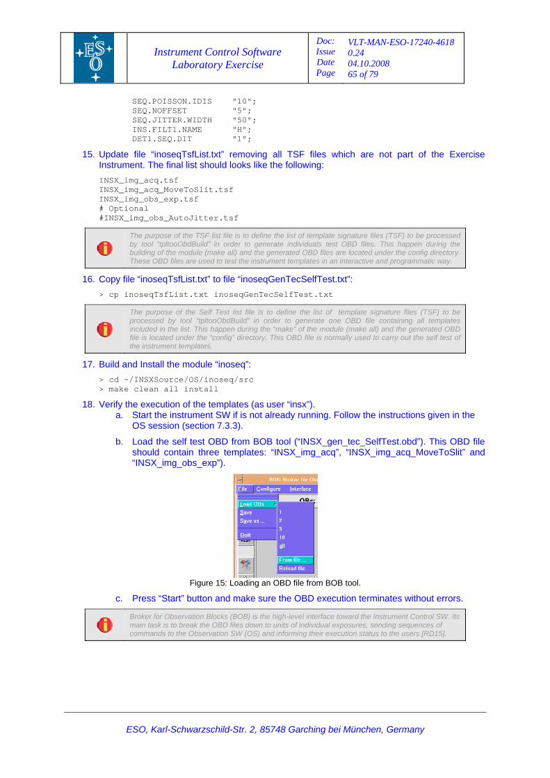
Instrument Control Software Laboratory Exercise
Doc: Issue Date Page
VLT-MAN-ESO-17240-4618 0.24 04.10.2008 65 of 79
ESO, Karl-Schwarzschild-Str. 2, 85748 Garching bei München, Germany
SEQ.POISSON.IDIS "10";
H"; 1";
15. oving all TSF files which are not part of the Exercise following:
INSX_iINSX_i
SEQ.NOFFSET "5"; SEQ.JITTER.WIDTH "50"; INS.FILT1.NAME "DET1.SEQ.DIT "
Update file “inoseqTsfList.txt” remInstrument. The final list should looks like the
INSX_img_acq.tsf mg_acq_MoveToSlit.tsf mg_obs_exp.tsf
# Optional #INSX_img_obs_AutoJitter.tsf
The purpose of the TSF list file is to define the list of template signature files (TSF) to be processed by tool “tpltooObdBuild” in order to generate individuals test OBD files. This happen during the building of the module (make all) and the generated OBD fil es are located under the config directory. These OBD files are used to test the instrument templates in an interactive and programmatic way.
> cp i
16. Copy file “inoseqTsfList.txt” to file “inoseqGenTecSelfTest.txt”:
noseqTsfList.txt inoseqGenTecSelfTest.txt
The purpose of the Self Test list file is to define the list of template signature files (TSF) to be processed by tool “tpltooObdBuild” in order to generate one OBD file containing all templates included in the list. This happen during the “make” of the module (make all) and th
e generated OBD
file is located under the “config” directory. This OBD file is normally used to carry out the self test of the instrument templates.
17. Build an
18. Verify thhe instructions given in the
from BOB tool (“INSX_gen_tec_SelfTest.obd”). This OBD file cq”, “INSX_img_acq_MoveToSlit” and
d Install the module “inoseq”: > cd ~/INSXSource/OS/inoseq/src > make clean all install
e execution of the templates (as user “insx”). tart the instrument SW if is not already running. Follow ta. S
OS session (section 7.3.3).
b. Load the self test OBDshould contain three templates: “INSX_img_a“INSX_img_obs_exp”).
Figure 15: Loading an OBD file from BOB tool.
c. nates without errors.
Press “Start” button and make sure the OBD execution termi
Broker for Observation Blocks (BOB) is the high-level interface toward the Instrument Control SW. Its main task is to break the OBD files down to units of individual exposures, sending sequences of commands to the Observation SW (O S) and informing their execution status to the users [RD15].
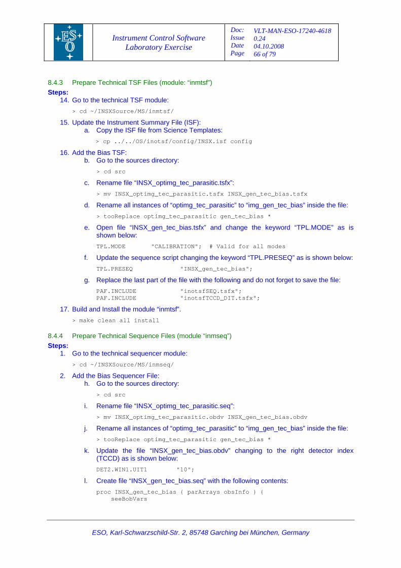
Instrument Control Software Laboratory Exercise
Doc: Issue Date Page
VLT-MAN-ESO-17240-4618 0.24 04.10.2008 66 of 79
ESO, Karl-Schwarzschild-Str. 2, 85748 Garching bei München, Germany
8.4.3 PrepareSteps:
14. Go to th
> cd ~
15. Update the Instruma.
notsf/config/INSX.isf config
c. NSX_optimg_tec_parasitic.tsfx”: parasitic.tsfx INSX_gen_tec_bias.tsfx
d. inside the file: tic gen_tec_bias *
e. ord “TPL.MODE” as is
he keyword “TPL.PRESEQ” as is shown below:
the file with the following and do not forget to save the file:
.tsfx"; _DIT.tsfx";
17. Build an
tall
8.4.4 Prepare dule “inmseq”)
h. Go to the sources directory:
rasitic” to “img_gen_tec_bias” inside the file:
> tooReplace optimg_tec_parasitic gen_tec_bias *
k. Update the file “INSX_gen_tec_bias.obdv” changing to the right detector index (TCCD) as is shown below:
DET2.WIN1.UIT1 "10";
l. Create file “INSX_gen_tec_bias.seq” with the following contents:
proc INSX_gen_tec_bias { parArrays obsInfo } { seeBobVars
Technical TSF Files (module: “inmtsf”)
e technical TSF module: /INSXSource/MS/inmtsf/
ent Summary File (ISF): Copy the ISF file from Science Templates: > cp ../../OS/i
16. Add the Bias TSF: b. Go to the sources directory:
> cd src
Rename file “I
> mv INSX_optimg_tec_
ename all instances of “optimg_tec_parasitic” to “img_gen_tec_bias”R
> tooReplace optimg_tec_parasi
Open file “INSX_gen_tec_bias.tsfx” and change the keywshown below:
TPL.MODE "CALIBRATION"; # Valid for all modes
f. pdate the sequence script changing t
UTPL.PRESEQ "INSX_gen_tec_bias";
g. Replace the last part ofPAF.INCLUDE "inotsfSEQPAF.INCLUDE "inotsfTCCD
d Install the module “inmtsf”. > make clean all ins
Technical Sequence Files (moSteps:
1. Go to the technical sequencer module:
/INSXSource/MS/inmseq/ > cd ~
2. Add the Bias Sequencer File:
> cd src
i. Rename file “INSX_optimg_tec_parasitic.seq”:
> mv INSX_optimg_tec_parasitic.obdv INSX_gen_tec_bias.obdv
j. Rename all instances of “optimg_tec_pa
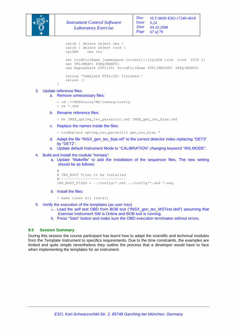
Instrument Control Software Laboratory Exercise
Doc: Issue Date Page
VLT-MAN-ESO-17240-4618 0.24 04.10.2008 67 of 79
ESO, Karl-Schwarzschild-Str. 2, 85748 Garching bei München, Germany
catch { delete object obs }
tplLog "Template $TPL(ID) finished." turn {}
> cd ~/INSXSource/MS/inmseq/config
sitic.ref INSX_gen_tec_bias.ref
c. eplace the names inside the files:
d. Adapt the file “INSX_gen_tec_bias.ref” to the correct detector index replacing “DET3” by “DET2”.
” changing keyword “INS.MODE”.
4. seq”: add the installation of the sequencer files. The new setting
be installed ---- .ref ../config/*.obd *.seq
l
5. Verify the execution of the templates (as user insx) ec_MSTest.obd”) assuming that
rument SW is Online and BOB tool is running. utton and make sure the OBD execution terminates without errors.
odules om the Template Instrument to specifics requirements. Due to the time constraints, the examples are
limited heless they outline the process that a developer would have to face when im s for an instrument.
catch { delete object tccd } tplOBS obs ino set tccdFullName [namespace current]::[tplACE tccd tccd TCCD 2] set TPL(NEXP) $SEQ(NEXPO) obs ExposeDark $TPL(ID) $tccdFullName $TPL(REFSUP) $SEQ(NEXPO)
re}
3. Update reference files: a. Remove unnecessary files:
> rm *.obd
b. Rename reference files:
> mv INSX_optimg_tec_para
R> tooReplace optimg_tec_parasitic gen_tec_bias *
e. Update default Instrument Mode to “CALIBRATION
Build and Install the module “inma. Update “Makefile” to
should be as follows:
# # INS_ROOT files to #---------------------------INS_ROOT_FILES = ../config/*
b. Install the files:
instal> make clean all
a. Load the self test OBD from BOB tool (“INSX_gen_tExercise Inst
b. Press “Start” b
8.5 Session Summary During this session the course participant has learnt how to adapt the scientific and technical mfr
and quite simple nevertplementing the template
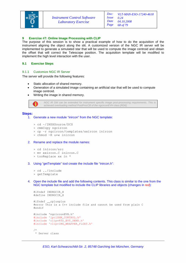
Instrument Control Software Laboratory Exercise
Doc: Issue Date Page
VLT-MAN-ESO-17240-4618 0.24 04.10.2008 68 of 79
ESO, Karl-Schwarzschild-Str. 2, 85748 Garching bei München, Germany
9 Ex IP The pu session is to show a practical example of how to do the acquisition of the instrum g the slit. A customized version of the NGC IR server will be implem d star that will be used to compute the image centroid and obtain the offs e acquisition template will be modified to implem
9.1 E
9.1.1 The ser features:
• red memory. • tion of a simulated image containing an artificial star that will be used to compute
oid. •
ercise #7: Online Image Processing with CLrpose of thisent aligning the object alon
ulateented to generate a simet that will correct the Telescope position. Th
t the high level interaction with the user. en
xercise Steps
Customize NGC IR Server ver will provide the following
Static enera
allocation of shaGimage centrWriting the image in shared memory.
NGC IR SW can be extended for instrument specific image post-processing requirements. This is achieved overloading method PostProcCB of the ngcirconEVH class [RD6].
Steps:
1. ” from the NGC template:
e/DCS cmmCopy ngcircon
con
2. ename and replace the module names:
3.
getTemplate
4. dd the following contents. This class is similar to the one from the clude the CLIP libraries and objects (changes in red):
ndef __cplusplus ed from plain C
OL.h"
clude "clipvRTD_EVT_SEND.h" clude "clipvIMG_WRAPPER_FLOAT.h"
Generate a new module “inircon
> cd ~/INSXSourc>> cp –r ngcircon/templates/xxircon inir chmod –R u+w inircon > R
> cd inircon/src > mv xxircon.C inircon.C
* > tooReplace xx in
Using “getTemplate” tool create the include file “inircon.h”: cd ../include >> Open the include file and aNGC template but modified to in
#ifndef INDNGCIR_H efine INDNGCIR_H #d
if#
#error This is a C++ include file and cannot be us#endif
h"#include "ngcirconEVH.nclude "ipclSHM_CONTR#i
#inin#
/*
* Server class
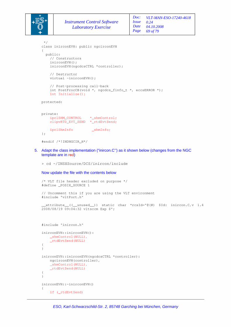
Instrument Control Software Laboratory Exercise
Doc: Issue Date Page
VLT-MAN-ESO-17240-4618 0.24 04.10.2008 69 of 79
ESO, Karl-Schwarzschild-Str. 2, 85748 Garching bei München, Germany
circonEVH
inirconEVH(); inirconEVH(ngcdcsCTRL *controller);
in PostP cCB(v *, eccsERROR *); int Initialize();
*_shmControl;
ip fo;
ndif
5. shown below (changes from the NGC
w up e with
Unco this if you are using the VLT environment
attribute__((__unused__)) static char *rcsId="@(#) $Id: inircon.C,v 1.4 08/08
nclu
(NULL), (NULL)
if (_rtdEvtSend)
*/ class inirconEVH: public ng{ public: // Constructors // Destructor
ual ~inirconEVH(); virt // Post-processing call-back t ro oid *, ngcdcs_finfo_t protected:
ivate: pr ipclSHM_CONTROL clipvRTD_EVT_SEND *_rtdEvtSend; clShmInfo _shmIn}; #e /*!INDNGCIR_H*/
Adapt the class implementation (“inircon.C’’) as ittemplate are in red) > cd ~/INSXSource/DCS/inircon/include
fil the contents below No date the /* VLT file header excluded on purpose */ #define _POSIX_SOURCE 1
mment //#include "vltPort.h" __20 /19 09:04:32 vltsccm Exp $"; #i de "i rcon.ni h" inirconEVH::inirconEVH():
_shmControl(NULL), _rtdEvtSend(NULL) { } inirconEVH::inirconEVH(ngcdcsCTRL *controller): ngcirconEVH(controller), hmContr _s ol _rtdEvtSend{ } inirconEVH::~inirconEVH() {
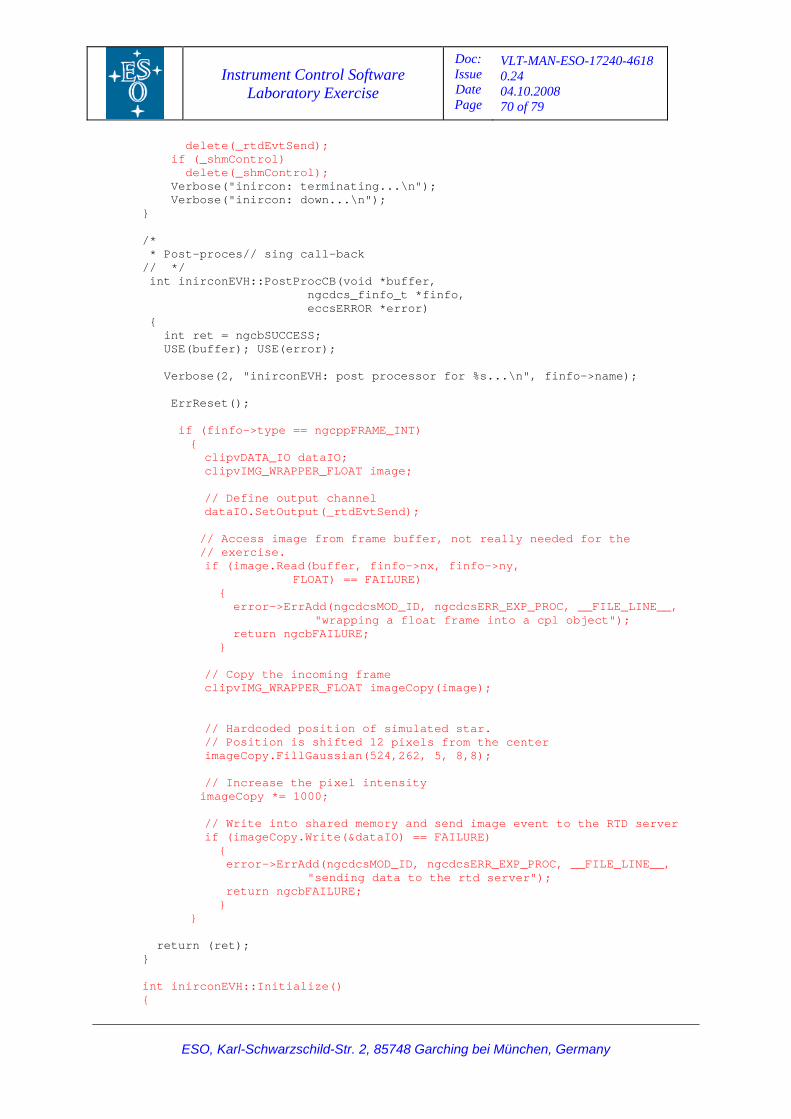
Instrument Control Software Laboratory Exercise
Doc: Issue Date Page
VLT-MAN-ESO-17240-4618 0.24 04.10.2008 70 of 79
ESO, Karl-Schwarzschild-Str. 2, 85748 Garching bei München, Germany
void *buffer, _finfo_t *finfo,
eccsERROR *error)
ame);
fer, not really needed for the
) == FAILURE)
"wrapping a float frame into a cpl object"); rn ngcbFAILURE;
}
e incoming frame
f simulated star. pixels from the center ,262, 5, 8,8);
d image event to the RTD server URE)
{
rtd server");
inirconEVH::Initialize()
delete(_rtdEvtSend); if (_shmControl) delete(_shmControl); Verbose("inircon: terminating...\n");
Verbose("inircon: down...\n"); } /*
roces// sing call-back * Post-p// */ int inirconEVH::PostProcCB( ngcdcs
{ int ret = ngcbSUCCESS; USE(buffer); USE(error); Verbose(2, "inirconEVH: post processor for %s...\n", finfo->n ErrReset(); if (finfo->type == ngcppFRAME_INT) { clipvDATA_IO dataIO; clipvIMG_WRAPPER_FLOAT image; // Define output channel dataIO.SetOutput(_rtdEvtSend);
cess image from frame buf // Ac // exercise. image.Read(buffer, finfo->nx, finfo->ny, if ( FLOAT
{ error->ErrAdd(ngcdcsMOD_ID, ngcdcsERR_EXP_PROC, __FILE_LINE__,
retu // Copy th
clipvIMG_WRAPPER_FLOAT imageCopy(image); // Hardcoded position o // Position is shifted 12
FillGaussian(524 imageCopy. // Increase the pixel intensity imageCopy *= 1000; // Write into shared memory and sen if (imageCopy.Write(&dataIO) == FAIL error->ErrAdd(ngcdcsMOD_ID, ngcdcsERR_EXP_PROC, __FILE_LINE__, "sending data to the
n ngcbFAILURE; retur } } return (ret); } int{
Instrument Control Software Laboratory Exercise
Doc: Issue Date Page
VLT-MAN-ESO-17240-4618 0.24 04.10.2008 71 of 79
ESO, Karl-Schwarzschild-Str. 2, 85748 Garching bei München, Germany
ESS;
Camera name is the index for shared memory configuration L("inocam");
ared memory with maximum size of the detector g shared memory (1024 * 1024 * (32/8) ...");
Allocate("inocam",4194304) == FAILURE)
Verbose(2,"Error allocating shared memory");
_ID, ngcdcsERR_EXP_PROC, __FILE_LINE__,
gcbFAILURE; }
to send RTD image events to the RTD Server ew clipvRTD_EVT_SEND("inocam",
hmId[0], _shmInfo.semId); RTD Server ring to the RTD server ..."); it() == FAILURE)
ErrAdd(ngcdcsMOD_ID, ngcdcsERR_EXP_PROC, __FILE_LINE__,
cbFAILURE;
return (ret);
ler; inirconEVH server(&controller);
ings
("NGCIRSW/ngc.cfg");
if (server.Initialize() == ngcbFAILURE) re /* * S
retu}
int ret = ngcbSUCC // _shmControl = new ipclSHM_CONTRO // Allocate the sh Verbose(2,"Allocatin if (_shmControl->
{ return FAILURE; } // Get shared memory information if (_shmControl->GetInfo("inocam", &_shmInfo) == FAILURE) { ErrAdd(ngcdcsMOD "Error getting shared memory information");
et = n r // Create object
vtSend = n _rtdE _shmInfo.s // Register to the Verbose(2,"Registe if (_rtdEvtSend->In
{ "Error registering to the RTD server"); ret = ng
}
} /* * Control server */ static int serverProcess(int argc, char **argv) { ngcdcsCTRL_CLASS control
int exitStatus; /* * Server default sett
*/ server.SysCfgDefault server.DbPointDefault("<alias>ngcircon");
turn (1);
erver main-loop */ exitStatus = ngcdcsServerProcess(&server, argc, argv);
rn (exitStatus);
Instrument Control Software Laboratory Exercise
Doc: Issue Date Page
VLT-MAN-ESO-17240-4618 0.24 04.10.2008 72 of 79
ESO, Karl-Schwarzschild-Str. 2, 85748 Garching bei München, Germany
*/ int main(int argc, char *argv[]) { int
/* * */
RE_OFF|ccsOBI_CLEANUP_ON, andler, &error) == FAILURE)
{ er
/* * C */ exit
exit}
6. Renam
> cd ../CDT
7. Go back to the sources and update the “Makefile” including the libraries needed by CLIP
(additio
8. uild and Install the module: > make all install
9. Modify NGC IR configuration according the new server name:
a. Stop NGC IR and OS SW if it they are running (as user “insx”): > ininsStop –proc NGCIR1 > ininsStop –proc OS
b. Go the configuration directory (as user “insxmgr”):
> cd ~/INSXSource/DCS/inngcir/config
/* * Main entry point
exitStatus; char procName[64]; ccsERROR error;
CCS init
memset(procName, 0, sizeof(procName)); ngcdcsSetEnv(argc, argv, procName); if (ccsInit(procName, ccsOBI_CA NULL, ngcdcsEvhKillH
rPrint(&error); exit(1); }
all server
Status = serverProcess(argc, argv); ccsE t(&error); xi
(exitStatus);
/*___oOo___*/
e the CDT file “xxircon.cdt”:
> mv xxircon.cdt inircon.cdt > tooReplace xxir inir ini*
nal libraries are in red):
inircon_LIBS = ngcirconLib $(ngcdcsLIBS) cplcore cpldrs rt ipcl clipm clipv
B
Instrument Control Software Laboratory Exercise
Doc: Issue Date Page
VLT-MAN-ESO-17240-4618 0.24 04.10.2008 73 of 79
ESO, Karl-Schwarzschild-Str. 2, 85748 Garching bei München, Germany
c. Change NGC IR configuration file (“inngcirNGCIR1.cfg”) with the new server name (keyword “DET.CON.SERVER”). The new setting should be like the following:
# Control server name DET.CON.SERVER "inircon";
d. Build and install module:
> cd ../src > make all install
10. Modify OS part of the Instrument Configuration according the new server name:
a. Go the configuration directory:
> cd ~/INSXSource/MS/inmcfg/config
b. Cha word
”). The new setting should be like the following:
# Control server name
c. Install the new configuration: > cd ../src
11. s user “insx”): eck that no errors are reported:
t –proc NGCIR1 t –proc OS
td –camera inocam
observation template (“INSX_img_obs_exp”). After the ge should appear in the RTD as is shown in Figure 16.
nge OS configuration file (“inmcfgINS.cfg”) with the new server name (key“OCS.DET1.PROCNAME
OCS.DET1.PROCNAME "inircon_NGCIR1";
> make all install
Verify that new server is working properly (aa. Start server and ch
> ininsStar> ininsStar
b. Put instrument software to state ONLINE from the OS Control Panel. c. Start RTD application and attach it to the camera events (menu “Real-Time”, option
Attach Camera): > r
d. Take an image running the exposure is finished, the ima
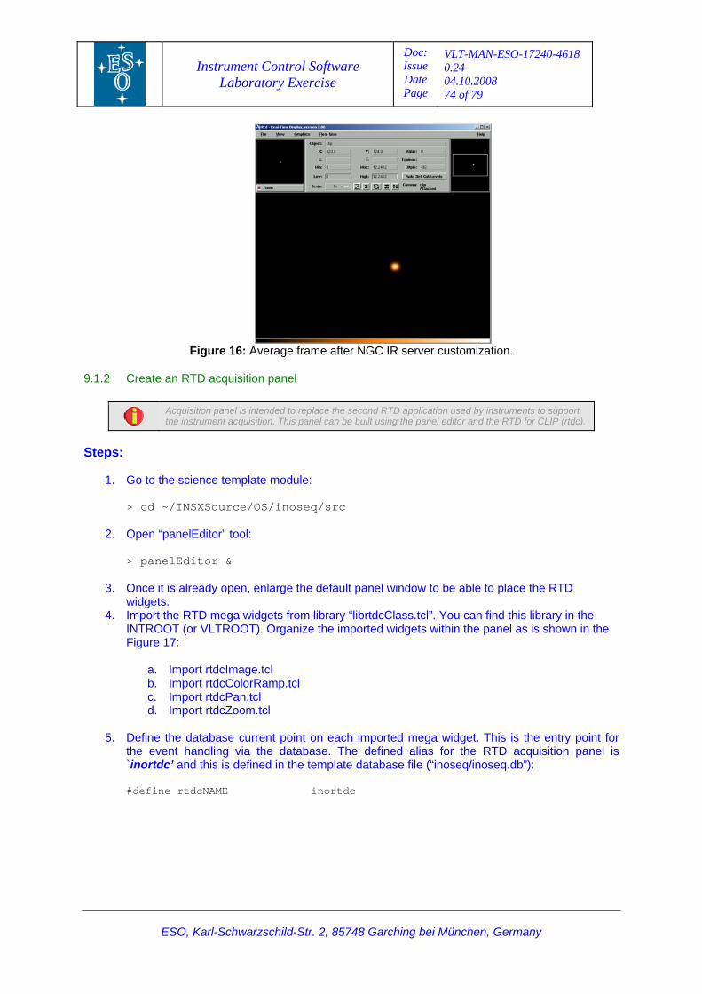
Instrument Control Software Laboratory Exercise
Doc: Issue Date Page
VLT-MAN-ESO-17240-4618 0.24 04.10.2008 74 of 79
Figure 16: Average frame after NGC IR server customization.
.1.2 Create an RTD acquisition panel 9
Acquisition panel is intended to replace the second RTD application used by instruments to support the instrument acquisition. This panel can be built using the panel editor and the RTD for CLIP (rtdc).
Steps:
> cd ~/INSXSource/OS/inoseq/src
2. Open “panelEditor” tool:
> panelEditor &
3. Once it is already open, enlarge the default panel window to be able to place the RTD widgets.
4. Import the RTD mega widgets from library “librtdcClass.tcl”. You can find this library in the INTROOT (or VLTROOT). Organize the imported widgets within the panel as is shown in the Figure 17:
a. Import rtdcImage.tcl b. Import rtdcColorRamp.tcl c. Import rtdcPan.tcl d. Import rtdcZoom.tcl
5. Define the database current point on each imported mega widget. This is the entry point for
the event handling via the database. The defined alias for the RTD acquisition panel is d this is defined in the template database file (“inoseq/inoseq.db”):
#define rtdcNAME
1. Go to the science template module:
`inortdc’ an
inortdc
ESO, Karl-Schwarzschild-Str. 2, 85748 Garching bei München, Germany
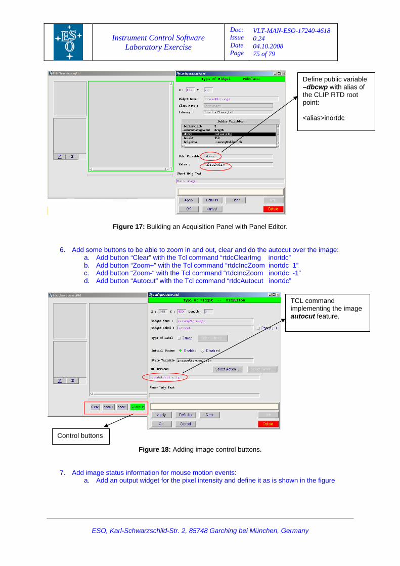
Instrument Control Software Laboratory Exercise
Doc: Issue Date Page
VLT-MAN-ESO-17240-4618 0.24 04.10.2008 75 of 79
ESO, Karl-Schwarzschild-Str. 2, 85748 Garching bei München, Germany
Figure 17: Building an Acquisition Panel with Panel Editor.
6. Add some buttons to be able to zoom in and out, clear and do the autocut over the image: a. Add button “Clear” with the Tcl command “rtdcClearImg inortdc” b. Add button “Zoom+” with the Tcl command “rtdcIncZoom inortdc 1” c. Add button “Zoom-“ with the Tcl command “rtdcIncZoom inortdc -1” d. Add button “Autocut” with the Tcl command “rtdcAutocut inortdc”
Figure 18: Adding image control buttons.
7. Add tion events: ntensity and define it as is shown in the figure
image status information for mouse mo. Add an output widget for the pixel ia
Define p–dbcwpthe CLIPpoi
ublic variable with alias of RTD root
nt: <alias>inortdc
TCL commandimplemen
ting the image
autocut feature.
Control buttons
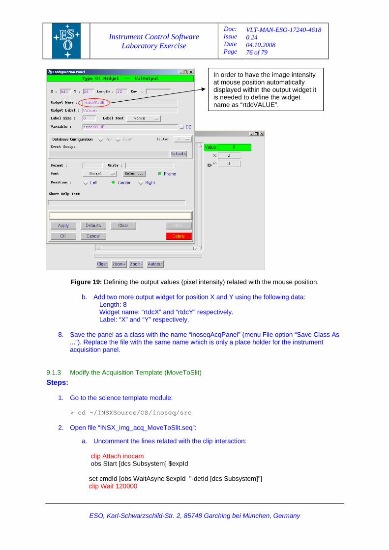
Instrument Control Software Laboratory Exercise
Doc: Issue Date Page
VLT-MAN-ESO-17240-4618 0.24 04.10.2008 76 of 79
In order to haat mouse position automati
ve the image intensity cally
displayed within the output widget it fine the widget ALUE”.
is needed to dename as “rtdcV
Figure 19: Defining the output values (pixel intensity) related with the mouse position.
b. Add two more output widget for position X and Y using the following data:
Length: 8 Widget name: “rtdcX” and “rtdcY” respectively. Label: “X” and “Y” respectively.
8. Save the panel as a class with the name “inoseqAcqPanel” (menu File option “Save Class As
...”). Replace the file with the same name which is only a place holder for the instrument acquisition panel.
.1.3 Modify the Acquiteps:
obs Start [dcs Subsystem] $expId set cmdId [obs WaitAsync $expId "-detId [dcs Subsystem]"] clip Wait 120000
9 sition Template (MoveToSlit) S
1. Go to the science template module:
> cd ~/INSXSource/OS/inoseq/src
2. Open file “INSX_img_acq_MoveToSlit.seq”:
a. Uncomment the lines related with the clip interaction:
clip Attach inocam
ESO, Karl-Schwarzschild-Str. 2, 85748 Garching bei München, Germany
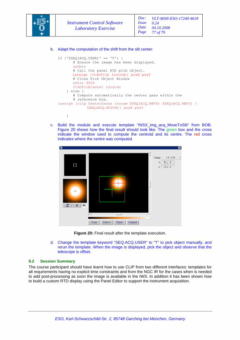
Instrument Control Software Laboratory Exercise
Doc: Issue Date Page
VLT-MAN-ESO-17240-4618 0.24 04.10.2008 77 of 79
ESO, Karl-Schwarzschild-Str. 2, 85748 Garching bei München, Germany
pt the computation of the shift from the slit center:
# Ensure the image has been displayed. update
rtdcPickCancel inortdc
center gass within the # reference box.
[clip CenterGauss inocam $SEQ(ACQ.REFX) $SEQ(ACQ.REFY) \
emplate “INSX_img_acq_MoveToSlit” from BOB. ult should look like. The green box and the cross pute the centroid and its centre. The red cross
b. Ada if {"$SEQ(ACQ.USER)" == "T"} {
# Call the panel RTD pick object. lassign [rtdcPick inortdc] posX posY # Close Pick Object Window after 4000 } else { # Compute automatically the
lassign $SEQ(ACQ.WIDTH)] posX posY }
c. Build the module and execute tFigure 20 shows how the final res
mindicate the window used to coindicates where the centre was computed.
d. Change the template keyword “SEQ.ACQ.USER” to “T” to pick object manually, and displayed, pick the object and observe that the
telescope is offset.
9.2 The two different interfaces: templates for all re R for the cases when is needed to ad . In addition it has been shown how to bu support the instrument acquisition.
Figure 20: Final result after the template execution.
rerun the template. When the image is
Session Summary course participant should have learnt how to use CLIP from
from the NGC Iquirements having no explicit time constraints andd post-processing as soon the image is available in the IWSild a custom RTD display using the Panel Editor to
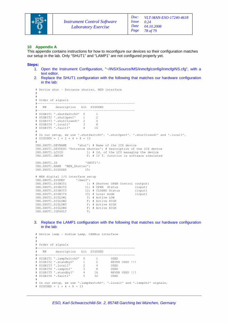
Instrument Control Software Laboratory Exercise
Doc: Issue Date Page
VLT-MAN-ESO-17240-4618 0.24 04.10.2008 78 of 79
ESO, Karl-Schwarzschild-Str. 2, 85748 Garching bei München, Germany
10 This ir configuration matches our s t. Step
1 ation, "~/INSXSource/MS/inmcfg/config/inmcfgINS.cfg", with a
2 th the following that matches our hardware configuration
--------
----------------------
4 8
16
", ".shutOpenI", ".shutClosedI" and ".localI",
hut"; # Name of the ICS device ce shutter"; # Description of the ICS device
S.SHUT1.SIGDEV "/men3";
INS.SHUT1.SIGBIT2 11; # OPEN Status (input) INS.SHUT1.SIGBIT3 12; # CLOSED Status (input) INS.SHUT1.SIGBIT4 10; # Local mode (input) INS.SHUT1.SIGLOW1 T; # Active LOW INS.SHUT1.SIGLOW2 F; # Active HIGH INS.SHUT1.SIGLOW3 F; # Active HIGH INS.SHUT1.SIGLOW4 F; # Active HIGH INS.SHUT1.IGFAULT T;
3. Replace the LAMP1 configuration with the following that matches our hardware configuration in the lab:
# Device lamp - Sodium Lamp, CANBus interface # # # Order of signals #----------------------------------------------------- # KW description bit SIGUSED #----------------------------------------------------- # SIGBIT1 ".lampSwitchO" 0 1 USED # SIGBIT2 ".standbyO" 1 2 NEVER USED !!! # SIGBIT3 ".localI" 2 4 USED # SIGBIT4 ".lampOnI" 3 8 USED # SIGBIT5 ".standbyI" 4 16 NEVER USED !!! # SIGBIT6 ".faultI" 5 32 USED # # In our setup, we use ".lampSwitchO", ".localI" and ".lampOnI" signals, # SIGUSED = 1 + 4 + 8 = 13
Appendix A appendix contains instructions for how to reconfigure our devices so theetup in the lab. Only “SHUT1” and “LAMP1” are not configured properly ye
s: . Open the Instrument Configur
text editor. . Replace the SHUT1 configuration wi
in the lab: # Device shut - Entrance shutter, MEN interface # # # Order of signals #---------------------------------------------
IGUSED # KW description bit S-------------------------------#
# SIGBIT1 ".shutSwitchO" 0 1 SIGBIT2 ".shutOpenI" 1 2 #
# SIGBIT3 ".shutClosedI" 2 # SIGBIT4 ".localI" 3 # SIGBIT5 ".faultI" 4 # # In our setup, we use ".shutSwitchO# SIGUSED = 1 + 2 + 4 + 8 = 15 # INS.SHUT1.DEVNAME "sINS.SHUT1.DEVDESC "EntranINS.SHUT1.LCUID 1; # Id. of the LCU managing the device INS.SHUT1.SWSIM F; # If T, function is software simulated INS.SHUT1.ID "SHUT1"; INS.SHUT1.NAME "MEN_Shutter"; INS.SHUT1.SIGUSED 15; # MEN digital I/O interface setup ININS.SHUT1.SIGBIT1 1; # Shutter OPEN Control (output)
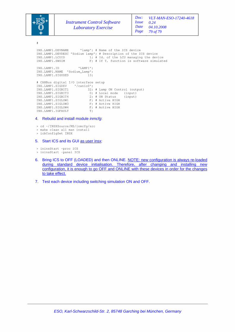
Instrument Control Software Laboratory Exercise
Doc: Issue Date Page
VLT-MAN-ESO-17240-4618 0.24 04.10.2008 79 of 79
ESO, Karl-Schwarzschild-Str. 2, 85748 Garching bei München, Germany
# INS.LAMP1.DEVNAME "lamp"; # Name of the ICS device INS.LAMP1.DEVDESC "Sodium lamp"; # Description of the ICS device INS.LAMP1.LCUID 1; # Id. of the LCU managing the device INS.LAMP1.SWSIM F; # If T, function is software simulated INS.LAMP1.ID "LAMP1"; INS.LAMP1.NAME "Sodium_Lamp"; INS.LAMP1.SIGUSED 13; # CANBus digital I/O interface setup INS.LAMP1.SIGDEV "/canio0"; INS.LAMP1.SIGBIT1 32; # Lamp ON Control (output) INS.LAMP1.SIGBIT3 0; # Local mode (input) INS.LAMP1.SIGBIT4 2; # ON Status (input) INS.LAMP1.SIGLOW1 F; # Active HIGH INS.LAMP1.SIGLOW3 F; # Active HIGH INS.LAMP1.SIGLOW4 F; # Active HIGH INS.LAMP1.IGFAULT T;
4. Rebuild and install module inmcfg: > cd ~/INSXSource/MS/inmcfg/src > make clean all man install > icbConfigSet INSX
5. Start ICS and its GUI Uas user insxU: > ininsStart –proc ICS > ininsStart –panel ICS
6. Bring ICS to OFF (LOADED) and then ONLINE. UNOTE: new configuration is always re-loaded during standard device initialisation. Therefore, after changing and installing new configuration, it is enough to go OFF and ONLINE with these devices in order for the changes to take effect.
7. Test each device including switching simulation ON and OFF.