Embed Size (px)
Citation preview
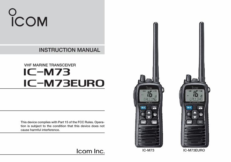
INSTRUCTION MANUAL
iM73VHF MARINE TRANSCEIVER
This device complies with Part 15 of the FCC Rules. Opera-tion is subject to the condition that this device does not cause harmful interference.
iM73EURO
IC-M73 IC-M73EURO
i
New2001
FOREWORDThank you for purchasing this Icom product. The IC-M73/IC-M73EURO vhf marine transceiver is designed and built with Icom’s state of the art technology and craftsmanship. With proper care, this product should provide you with years of trouble-free operation.
IMPORTANTREAD ALL INSTRUCTIONS carefully and complete-ly before using the transceiver.
SAVE THIS INSTRUCTION MANUAL — This in-struction manual contains important operating instruc-tions for the IC-M73/IC-M73EURO.
EXPLICIT DEFINITIONSWORD DEFINITION
RDANGER!Personal death, serious injury or an ex-plosion may occur.
RWARNING!Personal injury, fire hazard or electric shock may occur.
CAUTION Equipment damage may occur.
NOTEIf disregarded, inconvenience only. No risk of personal injury, fire or electric shock.
FEATURES☞ Submersible construction Built tough to withstand the punishing marine environ-
ment, the IC-M73/IC-M73EURO’s submersible con-struction meets IPX8 ratings of the International Stan-dard IEC 60529 (2001).
In addition, the speaker grill structure with a water self-draining Aquaquake function is helpful for easily remov-ing rain or seawater.
☞ Dualwatch and Tri-watch functions Convenient functions that allow you to monitor the dis-
tress channel (Ch 16) while receiving one other channel of your choice (Dualwatch), or while receiving one other channel of your choice and the Call channel (Tri-watch*). See page 16 for details.
* May not be available depending on the transceiver version.
☞ Voice recorder function IC-M73/IC-M73EURO has a voice recorder function*
which can automatically, or manually, record the re-ceived signal. The automatic (60 seconds) and manual (30 seconds) recordings are recorded separately into memory in the transceiver.
* May not be available depending on the transceiver version.
☞ Bass booster function The TX/RX bass booster functions* boosts the frequen-
cies to increase the bass level, if desired. * May not be available depending on the transceiver version.
ii
New2001
R short the terminals of the battery pack.
RUse and charge only specified Icom battery packs with Icom radios or Icom chargers. Only Icom battery packs are tested and approved for use with Icom radios or charged with Icom chargers. Using third-party or counterfeit battery packs or chargers may cause smoke, fire, or cause the battery to burst.
Rconnect the transceiver to an AC outlet. This may pose a fire hazard or result in an electric shock.
Rhold the transceiver so that the antenna is closer than 2.5 cm (1 inch) from exposed parts of the body, especially the face or eyes, while transmitting. The transceiver will perform best if the microphone is 5 to 10 cm (2 to 4 inches) away from the lips and the transceiver is vertical.
connect the transceiver to a power source other than the prod-ucts specified by Icom. Such a connection will ruin the trans-ceiver.
the flexible antenna and battery pack are securely attached to the transceiver, and that the antenna and battery pack are dry before attachment. Exposing the inside of the transceiver to water will result in serious damage to the transceiver.
The transceiver meets IPX8 requirements for waterproof pro-tection. However, once the transceiver has been dropped, wa-terproof protection cannot be guaranteed because of possible damage to the transceiver's case or the waterproof seal.
use or place the transceiver in direct sunlight or in areas with temperatures below –20°C (–4°F) or above +60°C (+140°F) for the EXP/USA versions, below –15°C (+5°F) or above +55°C (+131°F) for the CHN/EUR/FRG/HOL/UK versions, and below –10°C (+14°F) or above +55°C (+131°F) for the AUS versions.
use harsh solvents such as benzine or alcohol when cleaning, as they will damage the transceiver surfaces.
push [PTT] when not actually intending to transmit.
modify the transceiver. The transceiver warranty does not cover any problems caused by unauthorized modification.
operate the transceiver near unshielded electrical blasting caps or in an explosive atmosphere.the transceiver out of the reach of children.
the transceiver at least 0.9 meter (3.0 feet) away from your vessel’s magnetic navigation compass.
PRECAUTIONS
Icom, Icom Inc. and the Icom logo are registered trademarks of Icom Incorporated (Japan) in Japan, the United States, the United Kingdom, Germany, France, Spain, Russia and/or other countries.
iii
RADIO OPERATOR WARNINGYour Icom radio generates RF electromagnetic energy during transmit mode. This radio is designed for and clas-sified as “General Population Use” in an uncontrolled environment.
This radio has been evaluated for compliance at the dis-tance of 2.5 cm (1 inch) with the FCC and IC RF exposure limits for “General Population Use.” In addition, your Icom radio complies with the following Standards and Guidelines with regard to RF energy and electromagnetic energy lev-els and evaluation of such levels for exposure to humans:
• FCC OET Bulletin 65 Edition 01-01 Supplement C, Evaluating Compli-ance with FCC Guidelines for Human Exposure to Radio Frequency Electromagnetic Fields.
• American National Standards Institute (C95.1-1992), IEEE Standard for Safety Levels with Respect to Human Exposure to Radio Fre-quency Electromagnetic Fields, 3 kHz to 300 GHz.
• American National Standards Institute (C95.3-1992), IEEE Recom-mended Practice for the Measurement of Potentially Hazardous Elec-tromagnetic Fields– RF and Microwave.
• The following accessories are authorized for use with this prod-uct. Use of accessories other than those specified may result in RF exposure levels exceeding the FCC and IC requirements for wireless RF exposure.; Belt Clip (MB-103), Rechargeable Li-ion Battery Pack
(BP-245N).
To ensure that your expose to RF electromagnetic en-ergy is within the FCC and IC allowable limits for general population use, always adhere to the following guide-
lines:
• DO NOT operate the radio without a proper antenna attached, as this may damaged the radio and may also cause you to exceed FCC and IC RF exposure limits. A proper antenna is the antenna supplied with this radio by the manufacturer or antenna specifically authorized by the manufacturer for use with this radio.
• DO NOT transmit for more than 50% of total radio use time (“50% duty cycle”). Transmitting more than 50% of the time can cause FCC and IC RF exposure compliance requirements to be exceeded. The radio is transmitting when the “transmit indicator” appears on the LCD. You can cause the radio to transmit by pressing the “PTT” switch.
• ALWAYS keep the antenna at least 2.5 cm (1 inch) away from the body when transmitting and only use the Icom belt clip which is listed on page 43 when attaching the radio to your belt, etc., to ensure FCC and IC RF exposure compliance requirements are not exceeded. To provide the recipients of your transmission the best sound quality, hold the antenna at least 5 cm (2 inches) from your mouth, and slightly off to one side.
The information listed above provides the user with the information needed to make him or her aware of RF exposure, and what to do to as-sure that this radio operates with the FCC and IC RF exposure limits of this radio.
Electromagnetic Interference/CompatibilityDuring transmissions, your Icom radio generates RF energy that can pos-sibly cause interference with other devices or systems. To avoid such in-terference, turn off the radio in areas where signs are posted to do so. DO NOT operate the transmitter in areas that are sensitive to electromagnetic radiation such as hospitals, aircraft, and blasting sites.
WARNING
CAUTION
iv
AVERTISSEMENT POUR LES OPÉRATEURS RADIOVotre radio Icom produit une énergie électromagnétique de radiofréquences (RF), en mode de transmission. Elle est conçue pour une «utilisation grand public», dans un environnement non contrôlé. Cet appareil a été évalué et jugé conforme, à 2,5 cm, aux limites d'exposition aux RF de la FCC et d’IC, pour une «utilisation grand public». En outre, votre radio Icom satisfait les normes et directives qui suivent en matière de niveaux d'énergie et d'énergie électromagnétique de RF et d'évaluation de tels niveaux en ce qui concerne l'exposition humaine :
• Supplément C, édition 01-01, du Bulletin OET de la FCC, «Evaluating Compliance with FCC Guidelines for Human Exposure to Radio Frequency Electromagnetic Fields».
• Norme de l’American National Standards Institute (ANSI) : IEEE C95.1-1992 sur les niveaux de sécurité compatibles avec l’exposition humaine aux champs électromagnétiques de radiofréquences (3 kHz à 300 GHz).
• Norme de l’ANSI : IEEE C95.3-1992 sur la méthode d’évaluation recom-mandée du champ magnétique potentiellement dangereux des radio-fréquences et des micro-ondes.
• Les accessoires qui suivent sont approuvés pour une utilisation avec ce produit. L'utilisation d'accessoires autres que ceux précisés peut en-traîner des niveaux d'exposition aux RF supérieures aux limites établies par la FCC et d’IC en matière d'exposition aux RF sans fil; attache pour ceinture (MB-103), bloc-piles rechargeable au lithium-ion (BP-245N).
CAUTION Afin de vous assurer que votre exposition à une
énergie électromagnétique de RF se situe dans les limites permises par la FCC et d’IC pour une utilisation grand public, veuillez en tout temps respecter les directives suivantes :
• NE PAS faire fonctionner la radio sans qu'une antenne appropriée y soit fixée, car ceci risque d'endommager la radio et causer une exposition supérieure aux limites établies par la FCC et d’IC. L'antenne appropriée est celle qui est fournie avec cette radio par le fabricant ou une antenne spécialement autorisée par le fabricant pour être utilisée avec cette radio.
• NE PAS émettre pendant plus de 50% du temps total d'utilisation de l'appareil («50% du facteur d'utilisation»). Émettre pendant plus de 50% du temps total d'utilisation peut causer une exposition aux RF supérieure aux limites établies par la FCC et d’IC. La radio est en train d’émettre lorsque le témoin du mode de transmission s'affiche sur l'écran ACL. La radio émettra si vous appuyez sur le bouton du microphone.
• TOUJOURS tenir l'antenne éloignée d'au moins 2,5 cm de votre corps au moment d'émettre et utiliser uniquement l'attache pour ceinture Icom illustrée à la p. 43, lorsque vous attachez la radio à votre ceinture, ou à autre chose, de façon à vous assurer de ne pas provoquer une exposition aux RF supérieure aux limites fixées par la FCC et d’IC. Pour offrir à vos interlocuteurs la meilleure qualité de transmission possible, tenez l'antenne à au moins 5 cm de votre bouche et légèrement de côté.
Les renseignements ci-dessus fournissent à l'utilisateur toute l'information nécessaire sur l'exposition aux RF et sur ce qu'il faut faire pour assurer que cette radio fonctionne en respectant les limites d'exposition aux RF établies par la FCC et d’IC.
Interférence électromagnétique et compatibilitéEn mode de transmission, votre radio Icom produit de l'énergie de RF qui peut provoquer des interférences avec d'autres appareils ou systèmes. Pour éviter de telles interférences, mettez la radio hors tension dans les secteurs où une signalisation l’exige. NE PAS faire fonctionner l'émetteur dans des secteurs sensibles au rayonnement électromagnétique tels que les hôpitaux, les aéronefs et les sites de dynamitage.
A V E R T I S S E M E N T
MISE EN GARDE
v
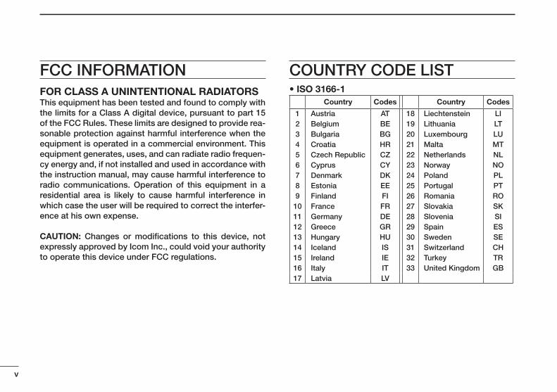
COUNTRY CODE LIST• ISO 3166-1
Country Codes Country Codes
1234567891011121314151617
AustriaBelgiumBulgariaCroatiaCzech RepublicCyprusDenmarkEstoniaFinlandFranceGermanyGreeceHungaryIcelandIrelandItalyLatvia
ATBEBGHRCZCYDKEEFIFRDEGRHUISIEITLV
18192021222324252627282930313233
LiechtensteinLithuaniaLuxembourgMaltaNetherlandsNorwayPolandPortugalRomaniaSlovakiaSloveniaSpainSwedenSwitzerlandTurkeyUnited Kingdom
LILTLUMTNLNOPLPTROSKSIESSECHTRGB
FOR CLASS A UNINTENTIONAL RADIATORSThis equipment has been tested and found to comply with the limits for a Class A digital device, pursuant to part 15 of the FCC Rules. These limits are designed to provide rea-sonable protection against harmful interference when the equipment is operated in a commercial environment. This equipment generates, uses, and can radiate radio frequen-cy energy and, if not installed and used in accordance with the instruction manual, may cause harmful interference to radio communications. Operation of this equipment in a residential area is likely to cause harmful interference in which case the user will be required to correct the interfer-ence at his own expense.
CAUTION: Changes or modifications to this device, not expressly approved by Icom Inc., could void your authority to operate this device under FCC regulations.
FCC INFORMATION
vi
New2001
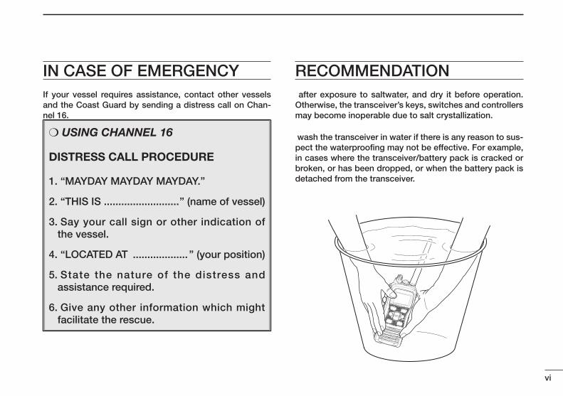
IN CASE OF EMERGENCYIf your vessel requires assistance, contact other vessels and the Coast Guard by sending a distress call on Chan-nel 16.
❍ USING CHANNEL 16
DISTRESS CALL PROCEDURE
1. “MAYDAY MAYDAY MAYDAY.”
2. “THIS IS ..........................” (name of vessel)
3. Say your call sign or other indication of the vessel.
4. “LOCATED AT ................... ” (your position)
5. State the nature of the distress and assistance required.
6. Give any other information which might facilitate the rescue.
RECOMMENDATION after exposure to saltwater, and dry it before operation. Otherwise, the transceiver’s keys, switches and controllers may become inoperable due to salt crystallization.
wash the transceiver in water if there is any reason to sus-pect the waterproofing may not be effective. For example, in cases where the transceiver/battery pack is cracked or broken, or has been dropped, or when the battery pack is detached from the transceiver.
New2001
vii
New2001
TABLE OF CONTENTSFOREWORD ...................................................................................... iIMPORTANT ...................................................................................... iEXPLICIT DEFINITIONS ................................................................... iFEATURES ........................................................................................ iPRECAUTIONS ................................................................................ iiRADIO OPERATOR WARNING ....................................................... iiiAVERTISSEMENT POUR LES OPÉRATEURS RADIO ................... ivFCC INFORMATION ........................................................................ vCOUNTRY CODE LIST .................................................................... vIN CASE OF EMERGENCY ............................................................. viRECOMMENDATION ...................................................................... viTABLE OF CONTENTS .................................................................. vii1 OPERATING RULES ..................................................................12 SUPPLIED ACCESSORIES AND ATTACHMENTS ............... 2–3 ■ Supplied accessories .............................................................2 ■ Attachments ............................................................................23 PANEL DESCRIPTION ........................................................... 4–7 ■ Front, top and side panels .....................................................4 ■ Function display .....................................................................64 BASIC OPERATION ............................................................. 8–13 ■ Channel selection ...................................................................8 ■ Receiving and transmitting ..................................................11 ■ Call channel programming ...................................................12 ■ Lock function ........................................................................12 ■ Monitor function ...................................................................12 ■ Adjusting the squelch level ..................................................13 ■ AquaQuake water draining function ....................................135 SCAN OPERATION (Except for the Dutch version) .......... 14–15 ■ Scan types ............................................................................14 ■ Setting Favorite channels.....................................................15 ■ Starting a scan ......................................................................15
6 DUALWATCH/TRI-WATCH ......................................................16 ■ Description ............................................................................16 ■ Operation ..............................................................................167 FUNCTION MODE OPERATION ........................................ 17–24 ■ About the function mode .....................................................17 ■ Manual recording function (Depending on versions) ..........18 ■ Automatic recording function (Depending on versions) ..........19 ■ Play back function (Depending on versions) .......................20 ■ Channel naming function .....................................................21 ■ Opening comment entry function ........................................22 ■ ATIS code programming (For only the Dutch and German versions).......................... 23 ■ Backlight function .................................................................248 SET MODE.......................................................................... 25–30 ■ SET mode programming ......................................................25 ■ SET mode items ...................................................................269 BATTERY CHARGING ........................................................ 31–34 ■ Battery cautions ...................................................................31 ■ Supplied battery charger......................................................33 ■ Optional battery chargers ....................................................3410 OPTIONAL SWIVEL BELT CLIP ..............................................35 ■ Attaching ...............................................................................35 ■ Detaching ..............................................................................3511 OPTIONAL SPEAKER-MICROPHONE ...................................36 ■ HM-167 descriptions ............................................................36 ■ Attaching ...............................................................................3612 TROUBLESHOOTING ..............................................................3713 SPECIFICATIONS ............................................................... 38–3914 VHF MARINE CHANNEL LIST ........................................... 40–4215 OPTIONS ..................................................................................43INDEX ...................................................................................... 44–45
1
1OPERATING RULES
New2001
12345678910111213141516
D Priorities• Read all rules and regulations pertaining to call priorities,
and keep an up-to-date copy handy. Safety and distress calls take priority over all others.
• You must monitor Channel 16 when you are not operating on another channel.
• False or fraudulent distress calls are prohibited under law.
D Privacy• Information overheard, but not intended for you, cannot
lawfully be used in any way.• Indecent or profane language is prohibited.
D Radio licenses(1) SHIP STATION LICENSEYou may require a current radio station license before us-ing the transceiver. It is unlawful to operate a ship station which is not licensed, but required to be.
If required, contact your dealer or the appropriate govern-ment agency for a Ship-Radiotelephone license applica-tion. This government-issued license states the call sign which is your craft’s identification for radio purposes.
(2) OPERATOR’S LICENSEA Restricted Radiotelephone Operator Permit is the license most often held by small vessel radio operators when a ra-dio is not required for safety purposes.
If required, the Restricted Radiotelephone Operator Permit must be posted or kept with the operator. If required, only a licensed radio operator may operate a transceiver.
However, non-licensed individuals may talk over a trans-ceiver if a licensed operator starts, supervises, ends the call and makes the necessary log entries.
A current copy of the applicable government rules and reg-ulations is only required to be on hand for vessels in which a radio telephone is compulsory. However, even if you are not required to have these on hand it is your responsibility to be thoroughly acquainted with all pertinent rules and regulations.
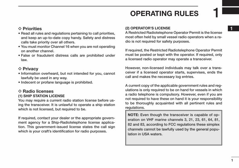
NOTE: Even though the transceiver is capable of op-eration on VHF marine channels 3, 21, 23, 61, 64, 81, 82 and 83, according to FCC regulations these simplex channels cannot be lawfully used by the general popu-lation in USA waters.
New2001
2
New2001
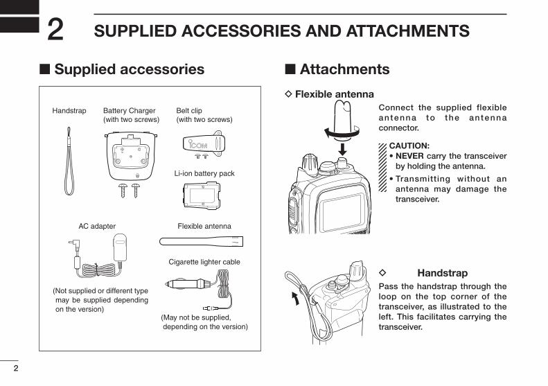
SUPPLIED ACCESSORIES AND ATTACHMENTS2■ Supplied accessories ■ Attachments
D Flexible antennaConnect the supplied flexible an tenna to the an tenna connector.
CAUTION: • NEVER carry the transceiver
by holding the antenna.
• Transmitting without an antenna may damage the transceiver.
D HandstrapPass the handstrap through the loop on the top corner of the transceiver, as illustrated to the left. This facilitates carrying the transceiver.
Flexible antenna
Cigarette lighter cable
Handstrap
(Not supplied or different type may be supplied depending on the version)
(May not be supplied, depending on the version)
Battery Charger(with two screws)
Belt clip(with two screws)
Li-ion battery pack
AC adapter
New2001
3
2SUPPLIED ACCESSORIES AND ATTACHMENTS
New2001
12345678910111213141516
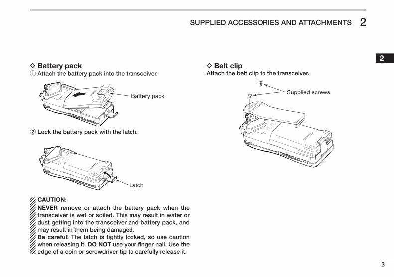
D Battery pack q Attach the battery pack into the transceiver.
Battery pack
w Lock the battery pack with the latch.
Latch
CAUTION: NEVER remove or attach the battery pack when the transceiver is wet or soiled. This may result in water or dust getting into the transceiver and battery pack, and may result in them being damaged.Be careful! The latch is tightly locked, so use caution when releasing it. DO NOT use your finger nail. Use the edge of a coin or screwdriver tip to carefully release it.
D Belt clipAttach the belt clip to the transceiver.
Supplied screws
New2001
4
New2001
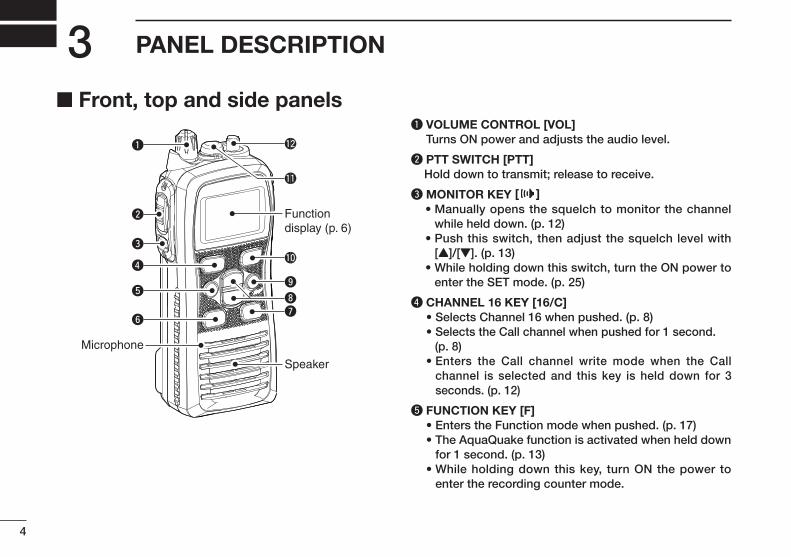
PANEL DESCRIPTION3■ Front, top and side panels
q
w
e
y
t
r
Microphone
!2
!1
!0
o
ui
Speaker
Functiondisplay (p. 6)
q VOLUME CONTROL [VOL] Turns ON power and adjusts the audio level.
w PTT SWITCH [PTT] Hold down to transmit; release to receive.
eMONITOR KEY [ ] • Manually opens the squelch to monitor the channel
while held down. (p. 12) • Push this switch, then adjust the squelch level with
[Y]/[Z]. (p. 13) • While holding down this switch, turn the ON power to
enter the SET mode. (p. 25)
r CHANNEL 16 KEY [16/C] • Selects Channel 16 when pushed. (p. 8) • Selects the Call channel when pushed for 1 second. (p. 8) • Enters the Call channel write mode when the Call
channel is selected and this key is held down for 3 seconds. (p. 12)
t FUNCTION KEY [F] • Enters the Function mode when pushed. (p. 17) • The AquaQuake function is activated when held down
for 1 second. (p. 13) • While holding down this key, turn ON the power to
enter the recording counter mode.
New2001
5
3PANEL DESCRIPTION
New2001
12345678910111213141516
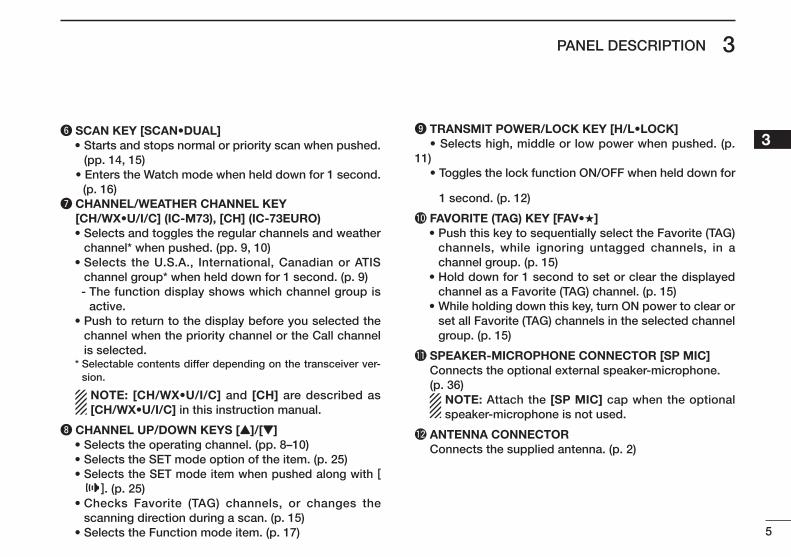
y SCAN KEY [SCAN•DUAL] • Starts and stops normal or priority scan when pushed.
(pp. 14, 15) • Enters the Watch mode when held down for 1 second. (p. 16)u CHANNEL/WEATHER CHANNEL KEY [CH/WX•U/I/C] (IC-M73), [CH] (IC-73EURO) • Selects and toggles the regular channels and weather
channel* when pushed. (pp. 9, 10) • Selects the U.S.A., International, Canadian or ATIS
channel group* when held down for 1 second. (p. 9) - The function display shows which channel group is
active. • Push to return to the display before you selected the
channel when the priority channel or the Call channel is selected.
* Selectable contents differ depending on the transceiver ver-sion.
NOTE: [CH/WX•U/I/C] and [CH] are described as [CH/WX•U/I/C] in this instruction manual.
i CHANNEL UP/DOWN KEYS [Y]/[Z] • Selects the operating channel. (pp. 8–10) • Selects the SET mode option of the item. (p. 25) • Selects the SET mode item when pushed along with [
]. (p. 25) • Checks Favorite (TAG) channels, or changes the
scanning direction during a scan. (p. 15) • Selects the Function mode item. (p. 17)
o TRANSMIT POWER/LOCK KEY [H/L•LOCK] • Selects high, middle or low power when pushed. (p. 11) • Toggles the lock function ON/OFF when held down for
1 second. (p. 12)
!0 FAVORITE (TAG) KEY [FAV•★] • Push this key to sequentially select the Favorite (TAG)
channels, while ignoring untagged channels, in a channel group. (p. 15)
• Hold down for 1 second to set or clear the displayed channel as a Favorite (TAG) channel. (p. 15)
• While holding down this key, turn ON power to clear or set all Favorite (TAG) channels in the selected channel group. (p. 15)
!1 SPEAKER-MICROPHONE CONNECTOR [SP MIC] Connects the optional external speaker-microphone. (p. 36) NOTE: Attach the [SP MIC] cap when the optional
speaker-microphone is not used.
!2 ANTENNA CONNECTOR Connects the supplied antenna. (p. 2)
6
3 PANEL DESCRIPTION
New2001
■
q
e
t
i
r
y
o
u
!0
!2
!3
!5!4
!6
!7
!1
w
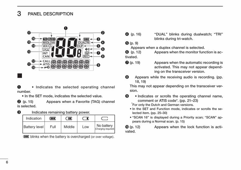
q • Indicates the selected operating channel number. • In the SET mode, indicates the selected value.
w (p. 15) Appears when a Favorite (TAG) channel is selected.
e Indicates remaining battery power.
Indication
Full Middle Low No battery(Charging required)
Battery level
blinks when the battery is overcharged (or over voltage).
r (p. 16) “DUAL” blinks during dualwatch; “TRI” blinks during tri-watch.
t(p. 9) Appears when a duplex channel is selected.y (p. 12) Appears when the monitor function is ac-tivated.
u(p. 19) Appears when the automatic recording is activated. This may not appear depend-ing on the transceiver version.
i Appears while the receiving audio is recording. (pp. 18, 19)
This may not appear depending on the transceiver ver-sion.
o • Indicates or scrolls the operating channel name, comment or ATIS code*. (pp. 21–23)
*For only the Dutch and German versions. • In the SET and Function mode, indicates or scrolls the se-
lected item. (pp. 25–30) • “SCAN 16” is displayed during a Priority scan; “SCAN” ap-
pears during a Normal scan. (p. 15)
!0(p. 12) Appears when the lock function is acti-vated.
7
3PANEL DESCRIPTION
New2001
1
3
5
7
9
11
13
15
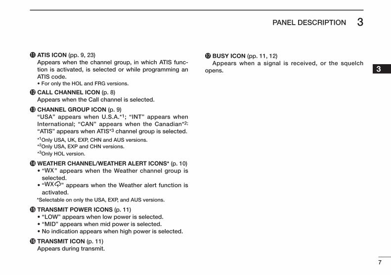
!1ATIS ICON (pp. 9, 23) Appears when the channel group, in which ATIS func-
tion is activated, is selected or while programming an ATIS code.
• For only the HOL and FRG versions.
!2CALL CHANNEL ICON (p. 8) Appears when the Call channel is selected.
!3CHANNEL GROUP ICON (p. 9) “USA” appears when U.S.A.*1; “INT” appears when
International; “CAN” appears when the Canadian*2;
“ATIS” appears when ATIS*3 channel group is selected. *1Only USA, UK, EXP, CHN and AUS versions. *2Only USA, EXP and CHN versions. *3Only HOL version.
!4 WEATHER CHANNEL/WEATHER ALERT ICONS* (p. 10) • “ ” appears when the Weather channel group is
selected. • “ ” appears when the Weather alert function is
activated. *Selectable on only the USA, EXP, and AUS versions.
!5TRANSMIT POWER ICONS (p. 11) • “LOW” appears when low power is selected. • “MID” appears when mid power is selected. • No indication appears when high power is selected.
!6TRANSMIT ICON (p. 11) Appears during transmit.
!7BUSY ICON (pp. 11, 12) Appears when a signal is received, or the squelch opens.
8
New2001New2001
4
New2001
■ Channel selectionIMPORTANT!: Prior to using the transceiver for the first time, fully charge the battery pack. This will help maxi-mize the capability and life of the battery. To avoid dam-age to the transceiver, turn OFF the radio while charg-
ing.
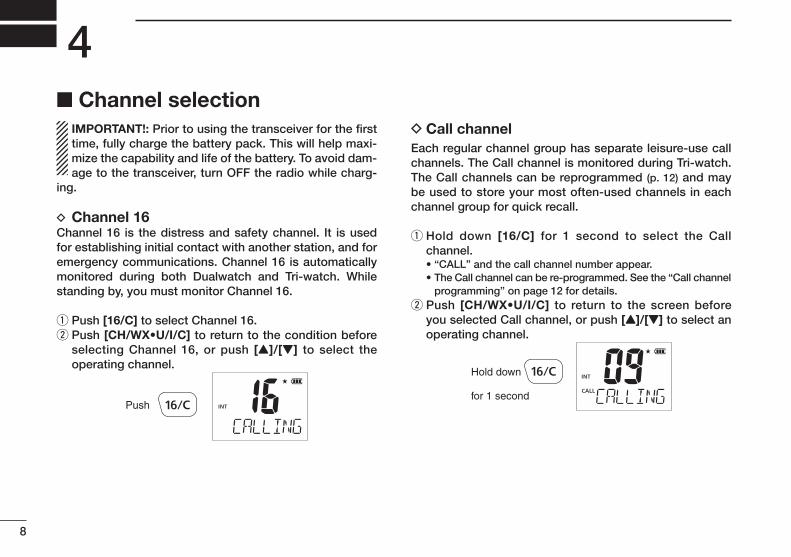
D Channel 16Channel 16 is the distress and safety channel. It is used for establishing initial contact with another station, and for emergency communications. Channel 16 is automatically monitored during both Dualwatch and Tri-watch. While standing by, you must monitor Channel 16.
q Push [16/C] to select Channel 16.w Push [CH/WX•U/I/C] to return to the condition before
selecting Channel 16, or push [Y]/[Z] to select the operating channel.
Push
D Call channelEach regular channel group has separate leisure-use call channels. The Call channel is monitored during Tri-watch. The Call channels can be reprogrammed (p. 12) and may be used to store your most often-used channels in each channel group for quick recall.
q Hold down [16/C] for 1 second to select the Call channel.
• “CALL” and the call channel number appear. • The Call channel can be re-programmed. See the “Call channel
programming” on page 12 for details.w Push [CH/WX•U/I/C] to return to the screen before
you selected Call channel, or push [Y]/[Z] to select an operating channel.
Hold down
for 1 second
New2001New2001
9
4BASIC OPERATION
New2001
2
4
6
8
10
12
14
16
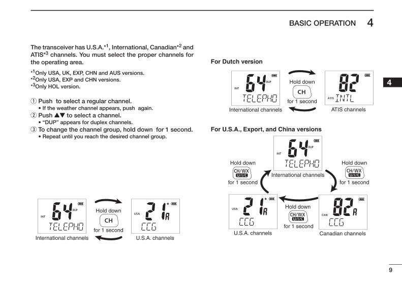
The transceiver has U.S.A.*1, International, Canadian*2 and ATIS*3 channels. You must select the proper channels for the operating area.
*1Only USA, UK, EXP, CHN and AUS versions.*2Only USA, EXP and CHN versions.*3Only HOL version.
q Push to select a regular channel. • If the weather channel appears, push again.
w Push YZ to select a channel. • “DUP” appears for duplex channels.ee eTo change the channel group, hold down for 1 second.
• Repeat until you reach the desired channel group.
U.S.A. channelsInternational channels
Hold down
for 1 second
Hold down
for 1 second
Hold down
for 1 second
Hold down
for 1 second
Hold down
for 1 second
For Dutch version
For U.S.A., Export, and China versions
International channels
International channels
U.S.A. channels
ATIS channels
Canadian channels
10
4 BASIC OPERATION
New2001
D Weather channelsThe transceiver has 10 pre-programmed weather chan-nels*. These are used for monitoring broadcasts from NOAA (National Oceanographic and Atmospheric Ad-ministration.) The transceiver can automatically detect a weather alert tone on the selected weather channel or while scanning.See the “SET mode items” on page 26 for details.* For only the USA, EXP, and AUS versions.
q Push [CH/WX•U/I/C] to select the weather channel group. w Push [Y]/[Z] to select a weather channel. e Push [CH/WX•U/I/C] to return to the screen before you selected the Weather channel group.
11
4BASIC OPERATION
New2001
2
4
6
8
10
12
14
16
■
CAUTION: Transmitting without an antenna may dam-age the transceiver.
q Rotate clockwise to turn ON power. • An opening comment scrolls across the function display. • Push to skip the opening comment.
w Set the volume and squelch level. ➥ Push , and push Z to open the squelch. ➥ Rotate to set the volume level. ➥ Push , and push YZ to set the squelch level.
e Push YZ to select the desired channel. • Pushing ★selects only Favorite channels. - When receiving a signal, the “” icon appears while audio is
heard from the speaker. - Further adjustment of may be necessary at this point.
r Push to select the output power, if necessary. - “LOW” appears when low power is selected; “MID” appears
when mid power is selected; no indication is displayed when high power is selected.
- Choose low or mid power to conserve battery power; choose high power for longer distance communications.
- Some channels are for only low transmission.et eHold down to transmit, and speak at your normal voice level.
- The appears while transmitting. - Channel 70 cannot be used for transmission.
y Release to receive.
To maximize the readability of your transmitted signal, pause a second after pushing . Hold the microphone 5 to 10 cm (2 to 4 inches) from your mouth, and speak at your normal voice level.
The transceiver has a power save function to conserve the battery power. The power save function automatically activates when no signal is received for 5 seconds.
To prevent accidental prolonged transmission, the trans-ceiver has a time-out timer function*. This timer cuts OFF a transmission after 5 minutes of continuous trans-mission.* For only the USA and AUS versions.
q Power ONw Set the volume
w Set the squelch level
w Set the squelch level
e Select the channel
r Set the output power
t Push to transmity Release to receive
Microphone
Speaker
12
4 BASIC OPERATION
New2001
12
■The Call channel key is used to select Channel 9* by default. However, you can program your most often-used channel in each channel group for quick recall. * The channel may differ, depending on the transceiver version.
q Hold down for 1 second several times to select the desired channel group (USA, INT, CAN, ATIS) to be pro-grammed.ew eHold down for 1 second to select the Call channel.
• “CALL” and Call channel number ap-pear.
e Hold down again for 3 seconds (un-til a long beep changes to 2 short beeps) to enter the Call channel program-ming mode.
• The Call channel number to be pro-grammed blinks.
er ePush YZ to select the desired channel.
t Push to program the displayed channel as the Call channel.
• The Call channel number stops blinking.
■This function electronically locks all keys (except for , and ) to prevent accidental channel changes and function access.➥ Push for 1 second to turn the lock function ON or OFF.
Hold down
for 1 second
Appears while the lockfunction is in use.
■The monitor function releases the noise squelch mute to check the volume level. See page 27 for details of the monitor switch action.➥ Hold down for 1 second to activate the monitor func-
tion. • “” and “” appear and audio is heard.
Appears while the monitor function is in use.
Hold down
for 1 second
13
4BASIC OPERATION
New2001
2
4
678910111213141516
■ Adjusting the squelch levelTo adjust the transceiver’s squelch level, use the [Y]/[Z] keys, as described below. In order to properly receive signals, as well as for the scan to function effectively operate, the squelch must be adjusted to the proper level.
q Push [ ], then adjust the squelch level with [Y]/[Z]. - “SQL” and the squelch level are displayed. - There are 11 squelch levels to choose from: OP is completely
open; 10 is tight squelch; 1 is loose squelch level. - When no key is pushed for 5 seconds, the transceiver returns to
its normal condition.w Push [ ] again to return to normal operating mode.
PushShows the squelchlevel.
Appears during squelch level adjustment
■ AquaQuake water draining functionThe AquaQuake water draining function clears water away from the speaker grill. Without this function, water may muffle the sound coming from the speaker. The transceiver emits a vibrating beep when this function is activated.
➥ While holding down [F], the AquaQuake function is acti-vated to clear water away from the speaker grill.
• Beep sounds, regardless of the volume level setting. • Activates for 10 seconds in maximum to drain water. • The transceiver never accepts key operation while the Aqua-
Quake function is activated. • The AquaQuake function can not be activated when an optional
speaker-microphone is connected.
New2001
14
New2001
SCAN OPERATION (Except for the Dutch version)5■ Scan typesScanning is an efficient way to quickly locate signals over a wide frequency range. The transceiver has a priority scan setting and normal scan setting.
In addition, the “Weather alert*” and “Auto scan” functions are also selectable for scanning. These functions can be simultaneously activated, depending on the settings in the SET mode. (pp. 26, 27)* For only the USA, EXP, and AUS versions.
Set the Favorite channels (scanned channel) before scan-ning. Clear those Favorite channels which are not needed or in-conveniently stop scanning, such as digital communica-tions.
Choose priority or normal scan in the SET mode. (p. 26)
NORMAL SCAN
CH 01 CH 02
WX*
CH 05 CH 04
CH 03
* Previously selected weather channel when weather alert function is ON.
Normal scan, like priority scan, sequentially searches through all Favorite channels. However, unlike priority scan, Channel 16 is not checked unless it is set as a Favorite channel.
PRIORITY SCAN
WX*
CH 01
CH 16
CH 02
CH 05 CH 04
CH 03
* Previously selected weather channel when weather alert function is ON
Priority scan sequentially searches through all Favorite channels while monitoring Channel 16. When a signal is detected on Channel 16, the scan pauses until the signal disappears; when a signal is detected on a channel other than Channel 16, scan becomes Dualwatch until the signal disappears.
New2001
15
5SCAN OPERATION (Except for the Dutch version)
New2001
12345678910111213141516
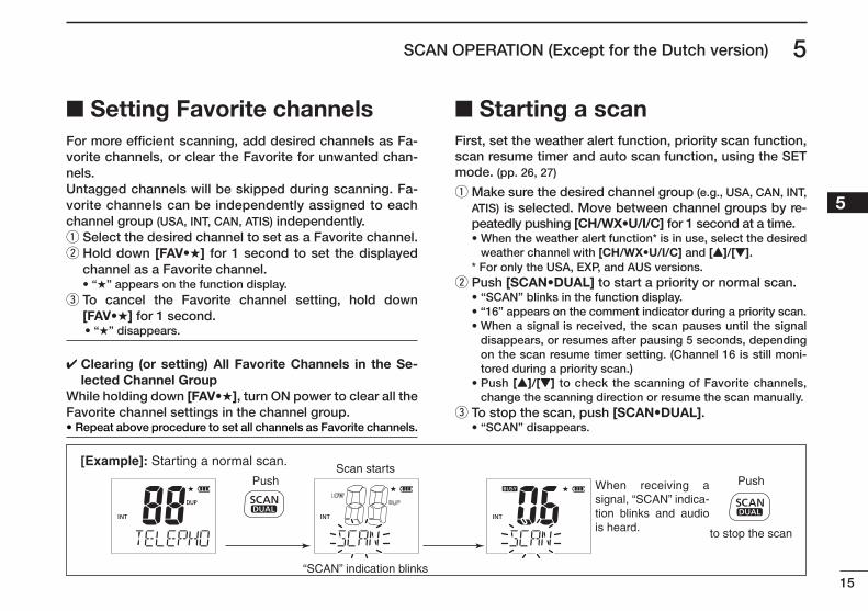
■ Setting Favorite channelsFor more efficient scanning, add desired channels as Fa-vorite channels, or clear the Favorite for unwanted chan-nels.Untagged channels will be skipped during scanning. Fa-vorite channels can be independently assigned to each channel group (USA, INT, CAN, ATIS) independently.
q Select the desired channel to set as a Favorite channel. w Hold down [FAV•★] for 1 second to set the displayed channel as a Favorite channel.
• “★” appears on the function display. e To cancel the Favorite channel setting, hold down [FAV•★] for 1 second.
✔ Clearing (or setting) All Favorite Channels in the Se-lected Channel Group
While holding down [FAV•★], turn ON power to clear all the Favorite channel settings in the channel group.• Repeat above procedure to set all channels as Favorite channels.
■ Starting a scanFirst, set the weather alert function, priority scan function, scan resume timer and auto scan function, using the SET mode. (pp. 26, 27)
q Make sure the desired channel group (e.g., USA, CAN, INT, ATIS) is selected. Move between channel groups by re-peatedly pushing [CH/WX•U/I/C] for 1 second at a time.
• When the weather alert function* is in use, select the desired weather channel with [CH/WX•U/I/C] and [Y]/[Z].
* For only the USA, EXP, and AUS versions.w Push [SCAN•DUAL] to start a priority or normal scan. • “SCAN” blinks in the function display. • “16” appears on the comment indicator during a priority scan. • When a signal is received, the scan pauses until the signal
disappears, or resumes after pausing 5 seconds, depending on the scan resume timer setting. (Channel 16 is still moni-tored during a priority scan.)
• Push [Y]/[Z] to check the scanning of Favorite channels, change the scanning direction or resume the scan manually.
e To stop the scan, push [SCAN•DUAL]. • “SCAN” disappears.
Scan starts
“SCAN” indication blinks
Push Push
to stop the scan
When receiving a signal, “SCAN” indica-tion blinks and audio is heard.
[Example]: Starting a normal scan.
• “★” disappears.
16
New2001
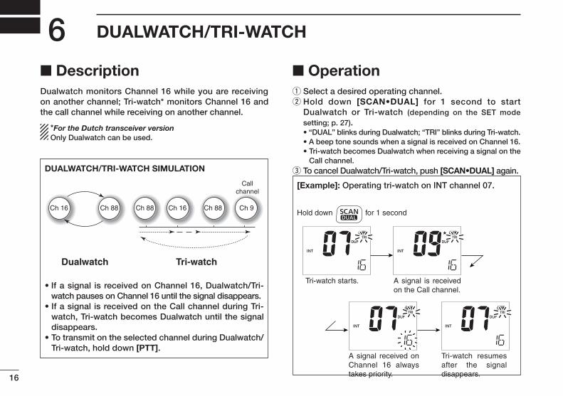
DUALWATCH/TRI-WATCH6■ DescriptionDualwatch monitors Channel 16 while you are receiving on another channel; Tri-watch* monitors Channel 16 and the call channel while receiving on another channel.
*For the Dutch transceiver version Only Dualwatch can be used.
■ Operationq Select a desired operating channel.w Hold down [SCAN•DUAL] for 1 second to start
Dualwatch or Tri-watch (depending on the SET mode setting; p. 27).
• “DUAL” blinks during Dualwatch; “TRI” blinks during Tri-watch. • A beep tone sounds when a signal is received on Channel 16. • Tri-watch becomes Dualwatch when receiving a signal on the
Call channel.e To cancel Dualwatch/Tri-watch, push [SCAN•DUAL] again.DUALWATCH/TRI-WATCH SIMULATION
Dualwatch Tri-watch
Callchannel
Ch 88Ch 16 Ch 88 Ch 16 Ch 88 Ch 9
• If a signal is received on Channel 16, Dualwatch/Tri-watch pauses on Channel 16 until the signal disappears.
• If a signal is received on the Call channel during Tri-watch, Tri-watch becomes Dualwatch until the signal disappears.
• To transmit on the selected channel during Dualwatch/Tri-watch, hold down [PTT].
[Example]: Operating tri-watch on INT channel 07.
A signal is received on the Call channel.
A signal received on Channel 16 always takes priority.
Tri-watch resumes after the signal disappears.
Tri-watch starts.
Hold down for 1 second
17
7FUNCTION MODE OPERATION
12345678910111213141516
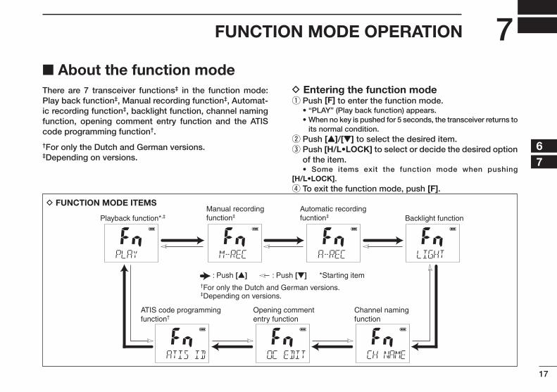
■ About the function modeThere are 7 transceiver functions‡ in the function mode: Play back function‡, Manual recording function‡, Automat-ic recording function‡, backlight function, channel naming function, opening comment entry function and the ATIS code programming function†.
†For only the Dutch and German versions.‡Depending on versions.
D Entering the function mode q Push [F] to enter the function mode.
• “PLAY” (Play back function) appears. • When no key is pushed for 5 seconds, the transceiver returns to
its normal condition.ew ePush [Y]/[Z] to select the desired item.ee ePush [H/L•LOCK] to select or decide the desired option of the item.
• Some items exit the function mode when pushing [H/L•LOCK].
r To exit the function mode, push [F].
D FUNCTION MODE ITEMS
Playback function*,‡Manual recordingfunction‡
Automatic recordingfucntion‡ Backlight function
ATIS code programmingfunction†
Opening commententry function
Channel namingfunction
: Push [Y] : Push [Z] *Starting item†For only the Dutch and German versions.‡Depending on versions.
18
7 FUNCTION MODE OPERATION
New2001
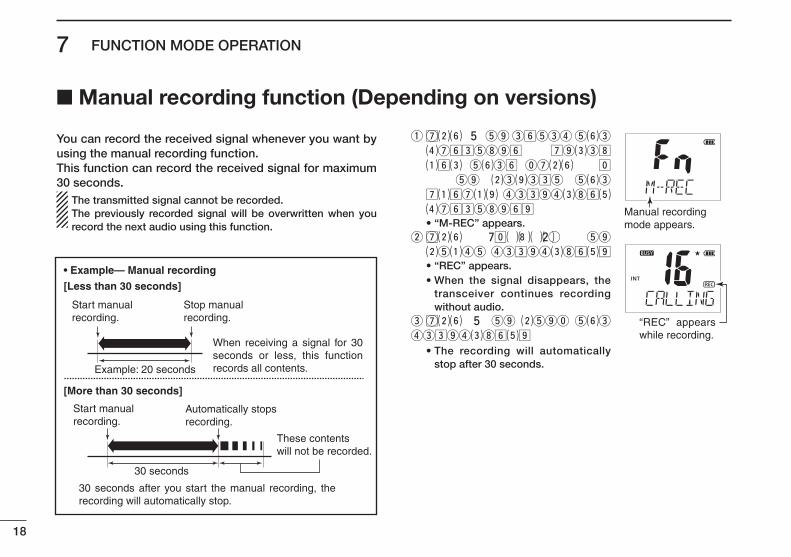
You can record the received signal whenever you want by using the manual recording function.This function can record the received signal for maximum 30 seconds. The transmitted signal cannot be recorded. The previously recorded signal will be overwritten when you
record the next audio using this function.
eq ePushe[F[etoeenterethee
functione mode,e
andethenepushe[[[/
[[[e toe selecte thee
manualerecordinge
function. • “M-REC” appears.ew ePushe [H/L•LOCK[e toe
starterecording. • “REC” appears. • When the signal disappears, the
transceiver continues recording without audio.
ee Pushe[F[etoestopethee
recording.
• The recording will automatically stop after 30 seconds.
Manual recordingmode appears.
“REC” appears while recording.
• Example— Manual recording
[Less than 30 seconds]
[More than 30 seconds]
Example: 20 seconds
30 seconds
When receiving a signal for 30 seconds or less, this function records all contents.
30 seconds after you start the manual recording, the recording will automatically stop.
These contentswill not be recorded.
Start manualrecording.
Start manualrecording.
Stop manualrecording.
Automatically stopsrecording.
■ Manual recording function (Depending on versions)
19
7FUNCTION MODE OPERATION
New2001
12345678910111213141516
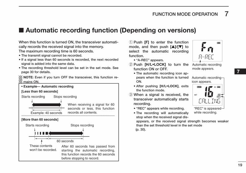
When this function is turned ON, the transceiver automati-cally records the received signal into the memory.The maximum recording time is 60 seconds.• The transmit signal cannot be recorded.• If a signal less than 60 seconds is recorded, the next recorded
signal is added into the same data.• The recording threshold level can be set in the set mode. See
page 30 for details.
NOTE: Even if you turn OFF the transceiver, this function re-mains ON.
q Push [F] to enter the function mode, and then push [Y]/[Z] to select the automatic recording function. • “A-REC” appears.ew ePush [H/L•LOCK] to turn the function ON or OFF.
• The automatic recording icon ap-pears when the function is turned ON.
• After pushing [H/L•LOCK], exits the function mode.
ee eWhen a signal is received, the transceiver automatically starts recording.
• “REC” appears while recording. • The recording will automatically
stop when the received signal dis-appears, or the received signal strength becomes weaker than the set threshold level in the set mode
(p. 30).
Automatic recordingmode appears.
“REC” is appeared while recording.
Automatic recording icon appears.
• Example— Automatic recording
[Less than 60 seconds]
[More than 60 seconds]
Example: 40 seconds
60 seconds
When receiving a signal for 60 seconds or less, this function records all contents.
After 60 seconds has passed from starting the automatic recording, this function records the 60 seconds before stopping to record.
These contentswon’t be recorded.
Starts recording
Starts recording
Stops recording
Stops recording
■ Automatic recording function (Depending on versions)
20
7 FUNCTION MODE OPERATION
New2001
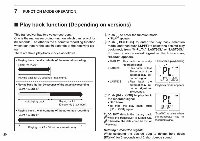
This transceiver has two voice recorders.One is the manual recording function which can record for 30 seconds. The other is the automatic recording function which can record the last 60 seconds of the receiving sig-nal.There are three play-back modes as follows.
q Push [F] to enter the function mode. • “PLAY” appears.
w Push [H/L•LOCK] to enter the play back selection mode, and then push [Y]/[Z] to select the desired play back mode from “M-PLAY,” “LAST30S,” or “LAST60S.”
If there is no recorded signal in the transceiver, “BLANK” appears.
• M-PLAY : Play back the manually recorded signal.
• LAST30S : Play back the last 30 seconds of the automaticaliy re-corded signal.
• LAST60S : Play back the automaticaliy re-corded signal for 60 seconds.
e Push [H/L•LOCK] to play back the recorded signal.
• “PL” blinks. • To stop the play back, push
[H/L•LOCK] again.
DO NOT detach the battery pack while the transceiver is turned ON. Otherwise, the data could be lost or deleted.
Deleting a recorded signal: While selecting the desired data to delete, hold down [FAV•★] for 3 seconds until 2 short beeps sound.
Blinks while playbacking.
Playback mode appears.
“BLANK” appears when the transceiver has no recorded signal.
• Playing back the all contents of the manual recording
• Playing back the last 30 seconds of the automatic recording
• Playing back the all contents of the automatic recording
Playing back for 30 seconds (maximum).
Select “M-PLAY”
Select “LAST60S”
Select “LAST30S”
Not playing back.
Playing back for 60 seconds (maximum).
Playing back for 30 seconds (maximum).
■ Play back function (Depending on versions)
21
7FUNCTION MODE OPERATION
New2001
12345678910111213141516
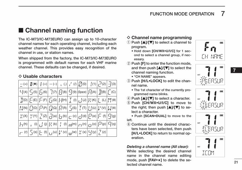
■ Channel naming functionThe IC-M73/IC-M73EURO can assign up to 10-character channel names for each operating channel, including each weather channel. This provides easy recognition of the channel in use, or station names.
When shipped from the factory, the IC-M73/IC-M73EURO is programmed with default names for each VHF marine channel. These defaults can be changed, if desired.
D Usable characters
D Channel name programming q Push [Y]/[Z] to select a channel to program.
• Hold down [CH/WX•U/I/C] for 1 sec-ond to select a channel group, if nec-essary.
w Push [F] to enter the function mode, and then push [Y]/[Z] to select the channel naming function.
• “CH NAME” appears.ee ePush [H/L•LOCK] to edit the chan-nel name.
• The 1st character of the currently pro-grammed name blinks.
r Push [Y]/[Z] to select a character. t Push [CH/WX•U/I/C] to move to the right; then push [Y]/[Z] to se-lect a character.
• Push [SCAN•DUAL] to move to the left.
y Continue until the desired charac-ters have been selected, then push [H/L•LOCK] to return to normal op-eration.
Deleting a channel name (All clear): While selecting the desired channeI name in the channel name editing mode, push [FAV•★] to delete the se-lected channel name.
(=)
(4)
(D)
(N)
(X)
(h)
(r)
(�)
(5)
(E)
(O)
(Y)
(i)
(s)
(+)
(6)
(F)
(P)
(Z)
(j)
(t)
(7)
(G)
(Q)
(a)
(k)
(u)
(,)
(8)
(H)
(R)
(b)
(l)
(v)
(/)
(9)
(I)
(S)
(c)
(m)
(w)
(0)
(Space)
(J)
(T)
(d)
(n)
(x)
(1)
(A)
(K)
(U)
(e)
(o)
(y)
(2)
(B)
(L)
(V)
(f)
(p)
(z)
(3)
(C)
(M)
(W)
(g)
(q)
(–)

22
7 FUNCTION MODE OPERATION
New2001
The IC-M73/IC-M73EURO can assign up to 16-character opening comments.
You may replace the factory-set opening comment with a comment of your own. The opening comment appears each time the IC-M73/IC-M73EURO is powered ON. The comment may be up to 16 characters long.
You can use same characters as “Channel naming func-tion.” (p. 21)
D Opening comment programming q Push [F] to enter the function mode, and then push [Y]/[Z] to select the channel naming function.
• “OC EDIT” appears.ew ePush [H/L•LOCK] to edit the open-ing comment.
• The 1st character of the currently pro-grammed comment blinks.
e Push [Y]/[Z] to select a character.er ePush [CH/WX•U/I/C] to move to the right; then push [Y]/[Z] to se-lect a character.
• Pushing [SCAN•DUAL], moves to left. i Continue until the desired charac-ters have been entered, then push [H/L•LOCK] to return to normal op-eration.
Deleting the opening comment (All clear): While in the opening comment editing mode, push [FAV•★] to delete.
The programmed opening comment is briefly displayed or scrolled when the transceiver is powered ON.However, the opening comment display can be skipped by pushing [16/C].
■ Opening comment entry function
23
7FUNCTION MODE OPERATION
New2001
12345678910111213141516
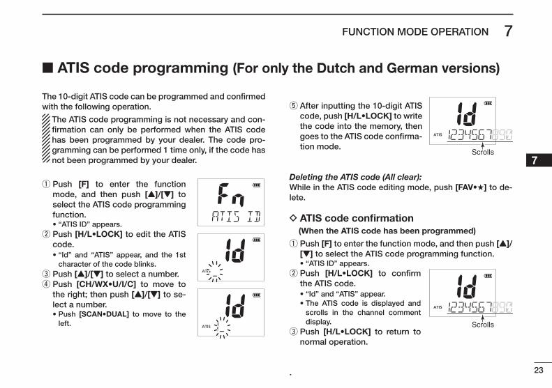
The 10-digit ATIS code can be programmed and confirmed with the following operation.
The ATIS code programming is not necessary and con-firmation can only be performed when the ATIS code has been programmed by your dealer. The code pro-gramming can be performed 1 time only, if the code has not been programmed by your dealer.
q Push [F] to enter the function mode, and then push [Y]/[Z] to select the ATIS code programming function.
• “ATIS ID” appears.ew ePush [H/L•LOCK] to edit the ATIS code.
• “Id” and “ATIS” appear, and the 1st character of the code blinks.
e Push [Y]/[Z] to select a number.er ePush [CH/WX•U/I/C] to move to the right; then push [Y]/[Z] to se-lect a number.
• Push [SCAN•DUAL] to move to the left.
t After inputting the 10-digit ATIS code, push [H/L•LOCK] to write the code into the memory, then goes to the ATIS code confirma-tion mode.
Deleting the ATIS code (All clear): While in the ATIS code editing mode, push [FAV•★] to de-lete.
D ATIS code confirmation (When the ATIS code has been programmed)
q Push [F] to enter the function mode, and then push [Y]/[Z] to select the ATIS code programming function.
• “ATIS ID” appears.ew ePush [H/L•LOCK] to confirm the ATIS code.
• “Id” and “ATIS” appear. • The ATIS code is displayed and
scrolls in the channel comment display.
ee ePush [H/L•LOCK] to return to normal operation.
.
Scrolls
Scrolls
■ ATIS code programming (For only the Dutch and German versions)
Scrolls
New2001
24
7 FUNCTION MODE OPERATION
New2001
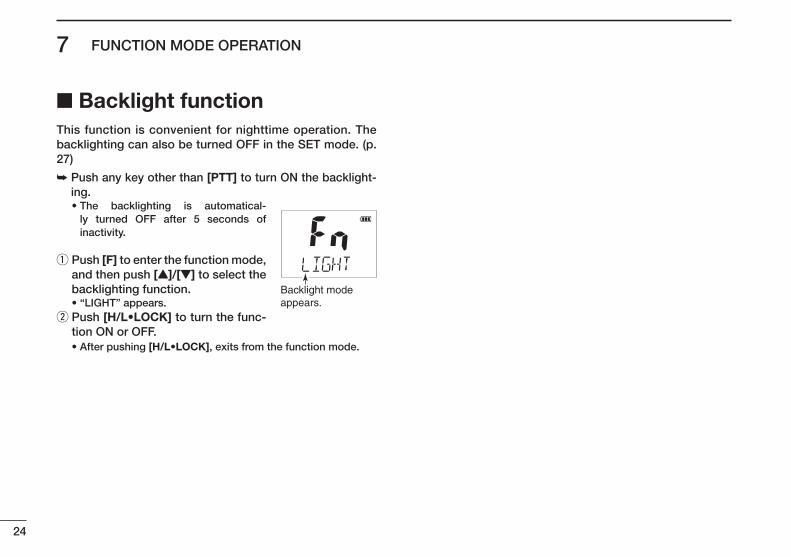
■ Backlight functionThis function is convenient for nighttime operation. The backlighting can also be turned OFF in the SET mode. (p. 27)
➥ Push any key other than [PTT] to turn ON the backlight-ing.
• The backlighting is automatical-ly turned OFF after 5 seconds of inactivity.
q Push [F] to enter the function mode, and then push [Y]/[Z] to select the backlighting function.
• “LIGHT” appears.ew ePush [H/L•LOCK] to turn the func-tion ON or OFF.
• After pushing [H/L•LOCK], exits from the function mode.
Backlight modeappears.
25
8SET MODE
New2001
12345678910111213141516
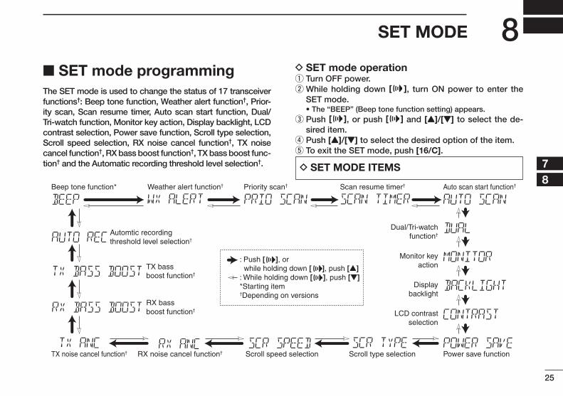
■ SET mode programmingThe SET mode is used to change the status of 17 transceiver functions†: Beep tone function, Weather alert function†, Prior-ity scan, Scan resume timer, Auto scan start function, Dual/Tri-watch function, Monitor key action, Display backlight, LCD contrast selection, Power save function, Scroll type selection, Scroll speed selection, RX noise cancel function†, TX noise cancel function†, RX bass boost function†, TX bass boost func-tion† and the Automatic recording threshold level selection†.
D SET mode operation q Turn OFF power.ew eWhile holding down [ ], turn ON power to enter the SET mode.
• The “BEEP” (Beep tone function setting) appears.ee ePush [ ], or push [ ] and [Y]/[Z] to select the de-sired item. r Push [Y]/[Z] to select the desired option of the item. t To exit the SET mode, push [16/C].
D SET MODE ITEMS
Beep tone function* Weather alert function† Priority scan† Scan resume timer† Auto scan start function†
Dual/Tri-watchfunction†
Monitor keyaction
Displaybacklight
LCD contrastselection
Automtic recordingthreshold level selection†
TX bass boost function†
RX bass boost function†
Power save functionScroll type selectionScroll speed selectionRX noise cancel function†TX noise cancel function†
: Push [ ], or while holding down [ ], push [Y]: While holding down [ ], push [Z]*Starting item†Depending on versions
26
8 SET MODE
New2001
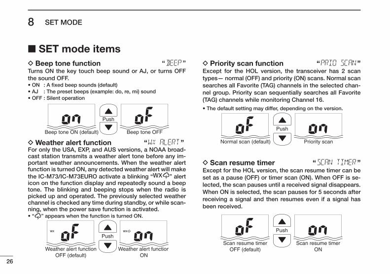
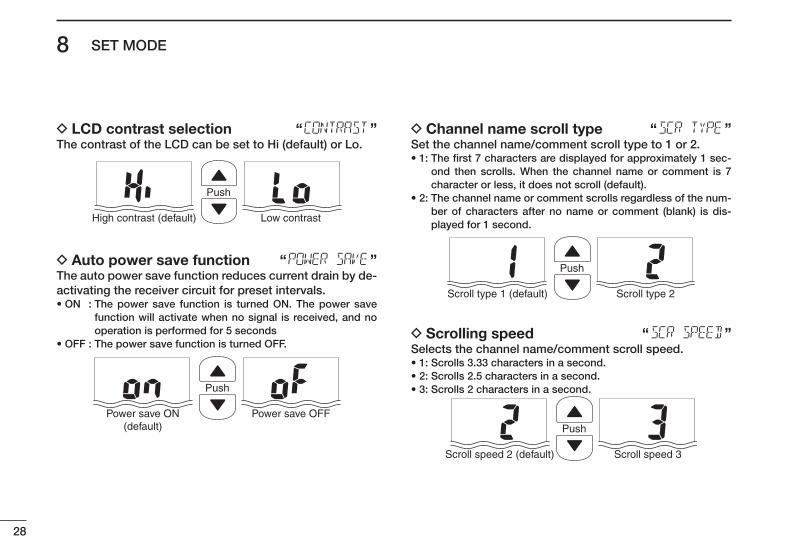
■ SET mode items D Beep tone function “ ”
Turns ON the key touch beep sound or AJ, or turns OFF the sound OFF.• ON : A fixed beep sounds (default)• AJ : The preset beeps (example: do, re, mi) sound• OFF : Silent operation
Push
Beep tone ON (default) Beep tone OFF
D Weather alert function “ ”For only the USA, EXP, and AUS versions, a NOAA broad-cast station transmits a weather alert tone before any im-portant weather announcements. When the weather alert function is turned ON, any detected weather alert will make the IC-M73/IC-M73EURO activate a blinking “ ” alert icon on the function display and repeatedly sound a beep tone. The blinking and beeping stops when the radio is picked up and operated. The previously selected weather channel is checked any time during standby, or while scan-ning, when the power save function is activated.• “ ” appears when the function is turned ON.
Push
Weather alert functionOFF (default)
Weather alert functionON
D Priority scan function “ ”Except for the HOL version, the transceiver has 2 scan types— normal (OFF) and priority (ON) scans. Normal scan searches all Favorite (TAG) channels in the selected chan-nel group. Priority scan sequentially searches all Favorite (TAG) channels while monitoring Channel 16.• The default setting may differ, depending on the version.
Push
Normal scan (default) Priority scan
D Scan resume timer “ ”Except for the HOL version, the scan resume timer can be set as a pause (OFF) or timer scan (ON). When OFF is se-lected, the scan pauses until a received signal disappears. When ON is selected, the scan pauses for 5 seconds after receiving a signal and then resumes even if a signal has been received.
Push
Scan resume timerOFF (default)
Scan resume timerON
27
8SET MODE
New2001
12345678910111213141516
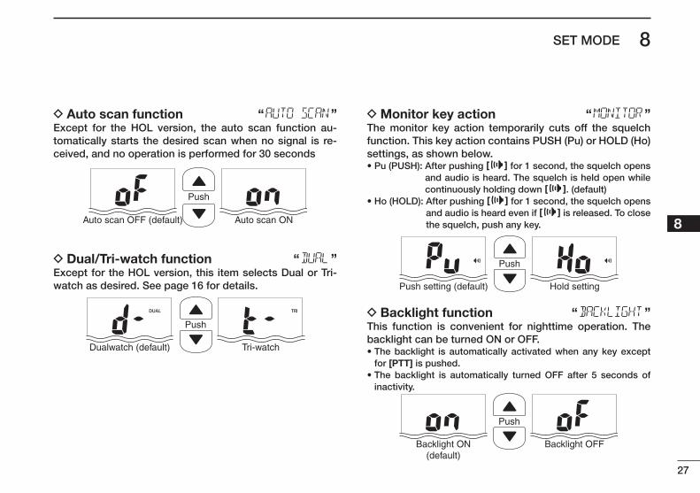
D Auto scan function “ ”Except for the HOL version, the auto scan function au-tomatically starts the desired scan when no signal is re-ceived, and no operation is performed for 30 seconds
Push
Auto scan OFF (default) Auto scan ON
D Dual/Tri-watch function “ ”Except for the HOL version, this item selects Dual or Tri-watch as desired. See page 16 for details.
Push
Dualwatch (default) Tri-watch
D Monitor key action “ ”The monitor key action temporarily cuts off the squelch function. This key action contains PUSH (Pu) or HOLD (Ho) settings, as shown below.• Pu (PUSH): After pushing [ ] for 1 second, the squelch opens
and audio is heard. The squelch is held open while continuously holding down [ ]. (default)
• Ho (HOLD): After pushing [ ] for 1 second, the squelch opens and audio is heard even if [ ] is released. To close the squelch, push any key.
Push
Push setting (default) Hold setting
D Backlight function “ ”This function is convenient for nighttime operation. The backlight can be turned ON or OFF.• The backlight is automatically activated when any key except
for [PTT] is pushed.• The backlight is automatically turned OFF after 5 seconds of
inactivity.
Push
Backlight ON(default)
Backlight OFF
28
8 SET MODE
New2001
D LCD contrast selection “ ”The contrast of the LCD can be set to Hi (default) or Lo.
Push
High contrast (default) Low contrast
D Auto power save function “ ”The auto power save function reduces current drain by de-activating the receiver circuit for preset intervals. • ON : The power save function is turned ON. The power save
function will activate when no signal is received, and no operation is performed for 5 seconds
• OFF : The power save function is turned OFF.
Push
Power save ON(default)
Power save OFF
D Channel name scroll type “ ”Set the channel name/comment scroll type to 1 or 2.• 1: The first 7 characters are displayed for approximately 1 sec-
ond then scrolls. When the channel name or comment is 7 character or less, it does not scroll (default).
• 2: The channel name or comment scrolls regardless of the num-ber of characters after no name or comment (blank) is dis-played for 1 second.
Push
Scroll type 1 (default) Scroll type 2
D Scrolling speed “ ”Selects the channel name/comment scroll speed.• 1: Scrolls 3.33 characters in a second.• 2: Scrolls 2.5 characters in a second.• 3: Scrolls 2 characters in a second.
Push
Scroll speed 2 (default) Scroll speed 3
29
8SET MODE
New2001
12345678910111213141516
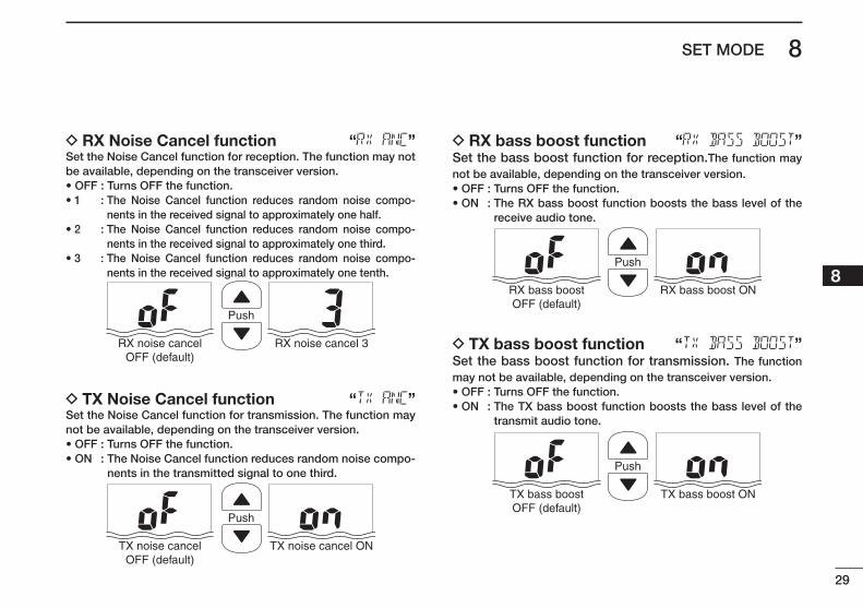
D RX Noise Cancel function “ ”Set the Noise Cancel function for reception. The function may not be available, depending on the transceiver version.• OFF : Turns OFF the function.• 1 : The Noise Cancel function reduces random noise compo-
nents in the received signal to approximately one half.• 2 : The Noise Cancel function reduces random noise compo-
nents in the received signal to approximately one third.• 3 : The Noise Cancel function reduces random noise compo-
nents in the received signal to approximately one tenth.
Push
RX noise cancelOFF (default)
RX noise cancel 3
D TX Noise Cancel function “ ”Set the Noise Cancel function for transmission. The function may not be available, depending on the transceiver version.• OFF : Turns OFF the function.• ON : The Noise Cancel function reduces random noise compo-
nents in the transmitted signal to one third.
Push
TX noise cancelOFF (default)
TX noise cancel ON
D RX bass boost function “ ”Set the bass boost function for reception.The function may not be available, depending on the transceiver version.• OFF : Turns OFF the function.• ON : The RX bass boost function boosts the bass level of the
receive audio tone.
Push
RX bass boostOFF (default)
RX bass boost ON
D TX bass boost function “ ”Set the bass boost function for transmission. The function may not be available, depending on the transceiver version.• OFF : Turns OFF the function.• ON : The TX bass boost function boosts the bass level of the
transmit audio tone.
Push
TX bass boostOFF (default)
TX bass boost ON
New2001
30
8 SET MODE
New2001
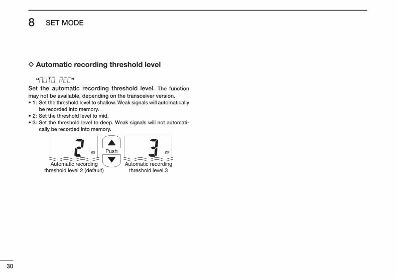
D Automatic recording threshold level “ ”
Set the automatic recording threshold level. The function may not be available, depending on the transceiver version.• 1 : Set the threshold level to shallow. Weak signals will automatically
be recorded into memory.• 2 : Set the threshold level to mid.• 3 : Set the threshold level to deep. Weak signals will not automati-
cally be recorded into memory.
Push
Automatic recordingthreshold level 2 (default)
Automatic recordingthreshold level 3
31
9BATTERY CHARGING
New2001
12345678910111213141516
■ Battery cautionsMisuse of Lithium-ion batteries may result in the follow-ing hazards: smoke, fire, or battery rupture. Misuse can also cause other battery damage or degrada-tion of battery performance.
• R DANGER! Use and charge only specified Icom battery pack with Icom transceiver. Only Icom battery pack is tested and approved for use with Icom transceiver. Us-ing third-party or counterfeit battery packs may cause smoke, fire, or cause the battery to burst.
D Battery caution• R DANGER! DO NOT hammer or otherwise impact the
battery. Do not use the battery if it has been severely im-pacted or dropped, or if the battery has been subjected to heavy pressure. Battery damage may not be visible on the outside of the case. Even if the surface of the battery does not show cracks or any other damage, the cells in-side the battery may rupture or catch fire.
• R DANGER! NEVER use or leave battery pack in areas with temperatures above +60˚C (+140˚F). High tempera-ture buildup in the battery, such as could occur near fires or stoves, inside a sun-heated car, or by setting the bat-tery in direct sunlight may cause the battery to rupture or catch fire. Excessive temperatures may also degrade battery performance or shorten battery life.
• R DANGER! DO NOT expose the battery to rain, snow, seawater, or any other liquids. Do not charge or use a wet battery. If the battery gets wet, be sure to wipe it dry before using. The battery by itself is not waterproof.
• R DANGER! NEVER incinerate a used battery pack since internal battery gas may cause a rupture or explosion.
• R DANGER! NEVER solder the battery terminals, or NEVER modify the battery pack. This may cause heat generation, and the battery may rupture, emit smoke or catch fire.
• R DANGER! Use the battery only with the transceiver for which it is specified. Never use a battery with any other equipment, or for any purpose that is not specified in this instruction manual.
• R DANGER! If fluid from inside the battery gets in your eyes, blindness can result. Rinse your eyes with clean water, without rubbing them, and see a doctor immedi-ately.
• R WARNING! Immediately stop using the battery if it emits an abnormal odor, heats up, or is discolored or de-formed. If any of these conditions occur, contact your Icom dealer or distributor.
• R WARNING! Immediately wash, using clean water, any part of the body that comes into contact with fluid from inside the battery.
32
9 BATTERY CHARGING
New2001
• R WARNING! NEVER put the battery in a microwave oven, high-pressure container, or in an induction heating cooker. This could cause overheating, a fire, or cause the battery to rupture.
• CAUTION: Always use the battery within the specified temperature range for the transceiver* and the battery itself (–20˚C to +60˚C; –4˚F to +140˚F).
* EXP/USA : –20˚C to +60˚C; –4˚F to +140˚F CHN/EUR/FRG/HOL/UK : –15˚C to +55˚C; +5˚F to +131˚F AUS : –10˚C to +55˚C; +14˚F to +131˚F
Using the battery out of its specified temperature range will reduce the battery’s performance and battery life. Please note that the specified temperature range of the battery may exceed that of the transceiver. In such cases, the transceiver may not work properly because it is out of its operating temperature range.
• CAUTION: Shorter battery life could occur if the battery is left fully charged, completely discharged, or in an ex-cessive temperature environment (above +50˚C; +122˚F) for an extended period of time. If the battery must be left unused for a long time, it must be detached from the radio after discharging. You may use the battery until the remaining capacity is about half, then keep it safely in a cool dry place with the temperature range as below;
–20˚C to +50˚C (–4˚F to +122˚F) (within a month) –20˚C to +35˚C (–4˚F to +95˚F) (within three months) –20˚C to +20˚C (–4˚F to +68˚F) (within a year)
D Charging caution• R DANGER! NEVER charge the battery pack in areas
with extremely high temperatures, such as near fires or stoves, inside a sun-heated car, or in direct sunlight. In such environments, the safety/protection circuit in the battery will activate, causing the battery to stop charg-ing.
• R WARNING! DO NOT charge or leave the battery in the battery charger beyond the specified time for charging. If the battery is not completely charged by the specified time, stop charging and remove the battery from the bat-tery charger. Continuing to charge the battery beyond the specified time limit may cause a fire, overheating, or the battery may rupture.
• R WARNING! NEVER insert the battery and transceiver (battery attached to the transceiver) into the charger if it is wet or soiled. This could corrode the battery charger terminals or damage the charger. The charger is not wa-terproof.
• CAUTION: DO NOT charge the battery outside of the specified temperature range: +10˚C to +40˚C (+50˚F to +104˚F). Icom recommends charging the battery at +20˚C (+68˚F). The battery may heat up or rupture if charged out of the specified temperature range. Additionally, battery performance or battery life may be reduced.
33
9BATTERY CHARGING
New2001
12345678910111213141516
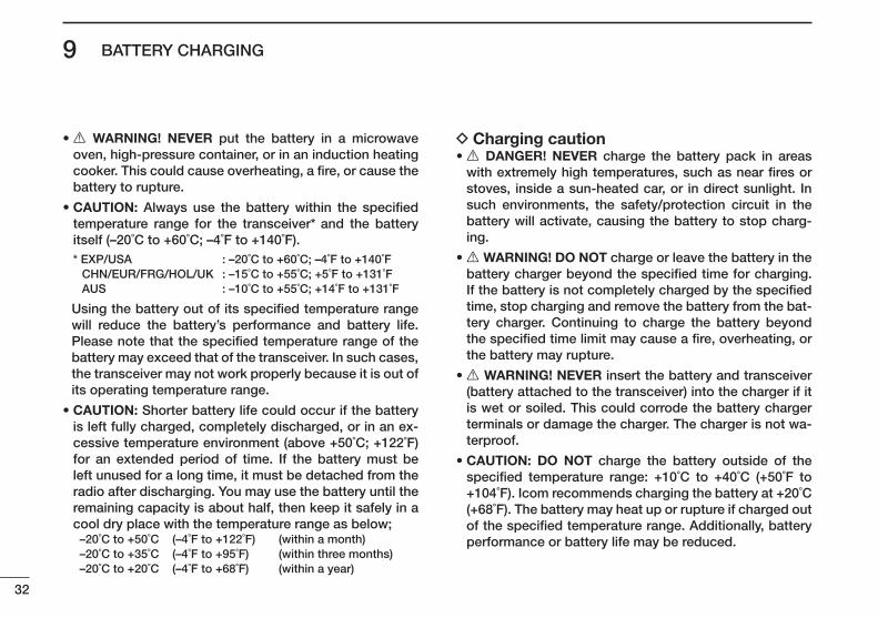
■ Supplied battery charger D BC-210 installation
q
w
e
Supplied screws
Supplied screws• To a desktop
• For added stability
• To a wall
Eyelet:Use a rubber band to secure the transceiver, if desired.
D Charging q Connect the AC adapter as shown below. w Insert the battery pack with or without the transceiver into the charger.
• The charge indicator lights orange.ee eCharge the battery pack approximately 2.5 hours, de-pending on the remaining power level.
• The charge indicator lights green when charging is complete.Transceiver
Battery pack
AC adapter
Chargerindicator
OPC-515L* (for a 13.8 V power source) or the CP-25H (for a 12 V cigarette lighter socket) can be used instead of the AC adapter.
CAUTION: NEVER connect the OPC-515L to a power source using reverse polarity. This will ruin the battery charger.White line: Black line :
*
Turn OFF the transceiver power while charging.
New2001
34
9 BATTERY CHARGING
New2001
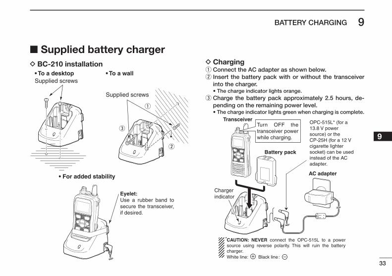
■ Optional battery chargers D AD-129 installation q Connect the 8-pin connector of the each charger slot to the AD-129 desktop charger adapter’s plug. w Install the adapter into the each charger slot in the di-rection of the arrow, then use the two supplied screws to secure the adapter to the charger.
D Rapid charging with the BC-197+BC-157S or OPC-656
The optional BC-197 with the BC-157S will simultaneously charge up to 6 Li-ion battery packs. The following items are additionally required. (Charging time: approximately 2.5 hours)• Six AD-129 charger adapters• An AC adapter (BC-157S) or the DC power cable (OPC-656)
Desktop charger adapter
8-pin connector
Suppliedscrews
Batterypack
The charger adapters are installed in each slot.
TransceiverTurn OFF power
(An AC adapter isnot supplied withsome versions.)
AC adapter
(Connect to a DC power supply: 12 to 16 V/at least 7 A)
Status indicator(each indicator independently functions)
DC power cable (OPC-656)
OPC-656*DC power cable
*
NEVER reverse the polarity when connecting the power cable to a power source. This will ruin the battery charger.Red line : + Black line : _
NEVER transmit near the BC-197 or the AC adapter while charging.
35
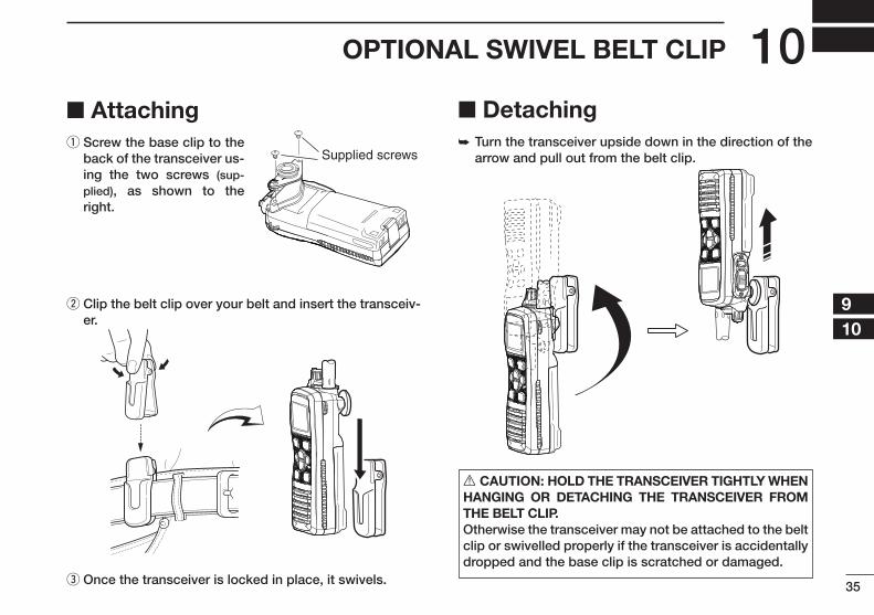
10OPTIONAL SWIVEL BELT CLIP
New2001
12345678910111213141516
■ Attaching q Screw the base clip to the back of the transceiver us-ing the two screws (sup-plied), as shown to the right.
w Clip the belt clip over your belt and insert the transceiv-er.
e Once the transceiver is locked in place, it swivels.
■ Detaching➥ Turn the transceiver upside down in the direction of the
arrow and pull out from the belt clip.
R CAUTION: HOLD THE TRANSCEIVER TIGHTLY WHEN HANGING OR DETACHING THE TRANSCEIVER FROM THE BELT CLIP.Otherwise the transceiver may not be attached to the belt clip or swivelled properly if the transceiver is accidentally dropped and the base clip is scratched or damaged.
Supplied screws
36
New2001New2001
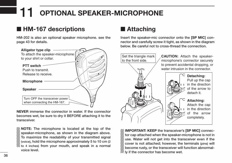
OPTIONAL SPEAKER-MICROPHONE11■ HM-167 descriptionsHM-202 is also an optional speaker microphone. see the page 43 for details.
NEVER immerse the connector in water. If the connector becomes wet, be sure to dry it BEFORE attaching it to the transceiver.
NOTE: The microphone is located at the top of the speaker-microphone, as shown in the diagram above. To maximize the readability of your transmitted signal (voice), hold the microphone approximately 5 to 10 cm (2 to 4 inches) from your mouth, and speak in a normal voice level.
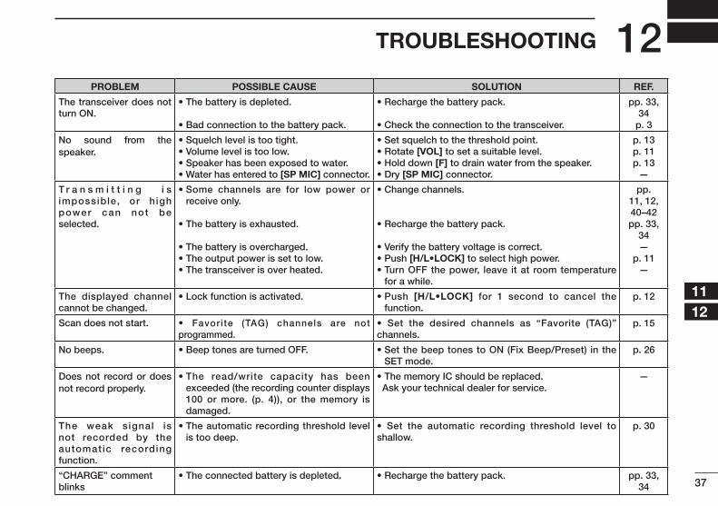
■ AttachingInsert the speaker-mic connector onto the [SP MIC] con-nector and carefully screw it tight, as shown in the diagram below. Be careful not to cross-thread the connection.
Set the triangle mark to the front side.
CAUTION: Attach the speaker- microphone’s connector securely to prevent accidental dropping, or water intrusion in the connector.
Detaching:Pull up the cap in the direction of the arrow to detach it.
Attaching:Attach the cap in the direction of the arrow completely.
IMPORTANT: KEEP the transceiver’s [SP MIC] connec-tor cap attached when the speaker-microphone is not in use. Water will not get into the transceiver even if the cover is not attached; however, the terminals (pins) will become rusty, or the transceiver will function abnormal-ly if the connector has become wet.
PTT switchPush to transmit.Release to receive.
Microphone
Speaker
Alligator type clipTo attach the speaker-microphoneto your shirt or collar.
Turn OFF the transceiver power when connecting the HM-167.
New2001
37
12TROUBLESHOOTING
12345678910111213141516
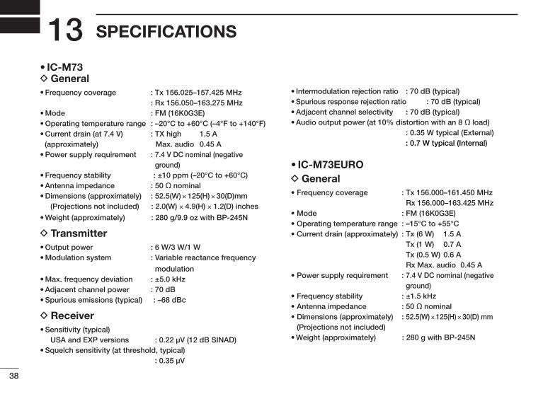
PROBLEM POSSIBLE CAUSE SOLUTION REF.
The transceiver does not turn ON.
• The battery is depleted.
• Bad connection to the battery pack.
• Recharge the battery pack.
• Check the connection to the transceiver.
pp. 33, 34
p. 3
No sound from the speaker.
• Squelch level is too tight.• Volume level is too low.• Speaker has been exposed to water.• Water has entered to [SP MIC] connector.
• Set squelch to the threshold point.• Rotate [VOL] to set a suitable level.• Hold down [F] to drain water from the speaker.• Dry [SP MIC] connector.
p. 13p. 11p. 13
—
T r a n s m i t t i n g i s impossible, or h igh power can not be selected.
• Some channels are for low power or receive only.
• The battery is exhausted.
• The battery is overcharged.• The output power is set to low.• The transceiver is over heated.
• Change channels.
• Recharge the battery pack.
• Verify the battery voltage is correct.• Push [H/L•LOCK] to select high power.• Turn OFF the power, leave it at room temperature
for a while.
pp. 11, 12, 40–42pp. 33,
34—
p. 11—
The displayed channel cannot be changed.
• Lock function is activated. • Push [H/L•LOCK] for 1 second to cancel the function.
p. 12
Scan does not start. • Favorite (TAG) channels are not programmed.
• Set the desired channels as “Favorite (TAG)” channels.
p. 15
No beeps. • Beep tones are turned OFF. • Set the beep tones to ON (Fix Beep/Preset) in the SET mode.
p. 26
Does not record or does not record properly.
• The read/write capacity has been exceeded (the recording counter displays 100 or more. (p. 4)), or the memory is damaged.
• The memory IC should be replaced. Ask your technical dealer for service.
—
The weak signal is not recorded by the automatic recording function.
• The automatic recording threshold level is too deep.
• Set the automatic recording threshold level to shallow.
p. 30
“CHARGE” comment blinks
• The connected battery is depleted. • Recharge the battery pack. pp. 33, 34
New2001
38
New2001
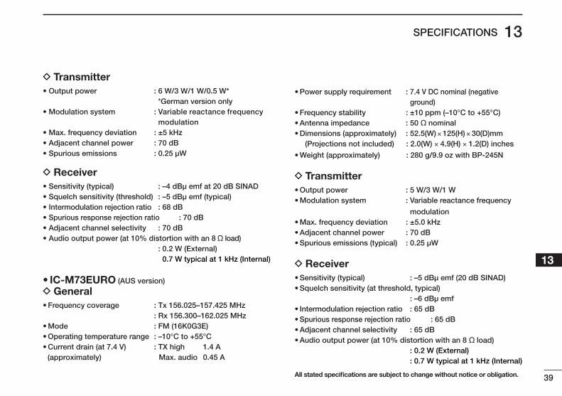
SPECIFICATIONS13• IC-M73
D General• Frequency coverage : Tx 156.025–157.425 MHz : Rx 156.050–163.275 MHz• Mode : FM (16K0G3E)• Operating temperature range : –20°C to +60°C (–4°F to +140°F)• Current drain (at 7.4 V) : TX high 1.5 A (approximately) Max. audio 0.45 A• Power supply requirement : 7.4 V DC nominal (negative
ground)• Frequency stability : ±10 ppm (–20°C to +60°C)• Antenna impedance : 50 ˘ nominal• Dimensions (approximately) : 52.5(W) × 125(H) × 30(D)mm (Projections not included) : 2.0(W) × 4.9(H) × 1.2(D) inches
• Weight (approximately) : 280 g/9.9 oz with BP-245N
D Transmitter• Output power : 6 W/3 W/1 W• Modulation system : Variable reactance frequency
modulation• Max. frequency deviation : ±5.0 kHz• Adjacent channel power : 70 dB• Spurious emissions (typical) : –68 dBc
D Receiver• Sensitivity (typical) USA and EXP versions : 0.22 µV (12 dB SINAD)• Squelch sensitivity (at threshold, typical) : 0.35 µV
• Intermodulation rejection ratio : 70 dB (typical)• Spurious response rejection ratio : 70 dB (typical)• Adjacent channel selectivity : 70 dB (typical)• Audio output power (at 10% distortion with an 8 ˘ load) : 0.35 W typical (External) : 0.7 W typical (Internal)
• IC-M73EURO D General
• Frequency coverage : Tx 156.000–161.450 MHz Rx 156.000–163.425 MHz
• Mode : FM (16K0G3E)• Operating temperature range : –15°C to +55°C• Current drain (approximately) : Tx (6 W) 1.5 A
Tx (1 W) 0.7 A Tx (0.5 W) 0.6 A Rx Max. audio 0.45 A
• Power supply requirement : 7.4 V DC nominal (negative ground)
• Frequency stability : ±1.5 kHz • Antenna impedance : 50 ˘ nominal• Dimensions (approximately) : 52.5(W) × 125(H) × 30(D) mm
(Projections not included) • Weight (approximately) : 280 g with BP-245N
New2001
39
13SPECIFICATIONS
New2001
12345678910111213141516
D Transmitter• Output power : 6 W/3 W/1 W/0.5 W*
*German version only• Modulation system : Variable reactance frequency
modulation• Max. frequency deviation : ±5 kHz• Adjacent channel power : 70 dB• Spurious emissions : 0.25 µW
D Receiver• Sensitivity (typical) : –4 dBµ emf at 20 dB SINAD• Squelch sensitivity (threshold) : –5 dBµ emf (typical)• Intermodulation rejection ratio : 68 dB • Spurious response rejection ratio : 70 dB • Adjacent channel selectivity : 70 dB • Audio output power (at 10% distortion with an 8 ˘ load) : 0.2 W (External)
0.7 W typical at 1 kHz (Internal)
• IC-M73EURO (AUS version)
D General• Frequency coverage : Tx 156.025–157.425 MHz : Rx 156.300–162.025 MHz• Mode : FM (16K0G3E)• Operating temperature range : –10°C to +55°C• Current drain (at 7.4 V) : TX high 1.4 A (approximately) Max. audio 0.45 A
• Power supply requirement : 7.4 V DC nominal (negative ground)
• Frequency stability : ±10 ppm (–10°C to +55°C)• Antenna impedance : 50 ˘ nominal• Dimensions (approximately) : 52.5(W) × 125(H) × 30(D)mm (Projections not included) : 2.0(W) × 4.9(H) × 1.2(D) inches
• Weight (approximately) : 280 g/9.9 oz with BP-245N
D Transmitter• Output power : 5 W/3 W/1 W• Modulation system : Variable reactance frequency
modulation• Max. frequency deviation : ±5.0 kHz• Adjacent channel power : 70 dB• Spurious emissions (typical) : 0.25 µW
D Receiver• Sensitivity (typical) : –5 dBµ emf (20 dB SINAD)• Squelch sensitivity (at threshold, typical) : –6 dBµ emf• Intermodulation rejection ratio : 65 dB • Spurious response rejection ratio : 65 dB • Adjacent channel selectivity : 65 dB • Audio output power (at 10% distortion with an 8 ˘ load) : 0.2 W (External) : 0.7 W typical at 1 kHz (Internal)
All stated specifications are subject to change without notice or obligation.
40
New2001New2001
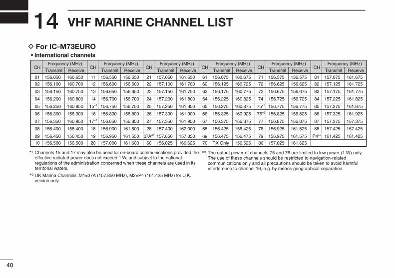
VHF MARINE CHANNEL LIST14• International channels
CHFrequency (MHz)
CHFrequency (MHz)
CHFrequency (MHz)
CHFrequency (MHz)
CHFrequency (MHz)
CHFrequency (MHz)
Transmit Receive Transmit Receive Transmit Receive Transmit Receive Transmit Receive Transmit Receive
01 156.050 160.650 11 156.550 156.550 21 157.050 161.650 61 156.075 160.675 71 156.575 156.575 81 157.075 161.675
02 156.100 160.700 12 156.600 156.600 22 157.100 161.700 62 156.125 160.725 72 156.625 156.625 82 157.125 161.725
03 156.150 160.750 13 156.650 156.650 23 157.150 161.750 63 156.175 160.775 73 156.675 156.675 83 157.175 161.775
04 156.200 160.800 14 156.700 156.700 24 157.200 161.800 64 156.225 160.825 74 156.725 156.725 84 157.225 161.825
05 156.250 160.850 15*1 156.750 156.750 25 157.250 161.850 65 156.275 160.875 75*3 156.775 156.775 85 157.275 161.875
06 156.300 156.300 16 156.800 156.800 26 157.300 161.900 66 156.325 160.925 76*3 156.825 156.825 86 157.325 161.925
07 156.350 160.950 17*1 156.850 156.850 27 157.350 161.950 67 156.375 156.375 77 156.875 156.875 87 157.375 157.375
P4*2 161.425 161.425
88 157.425 157.42508 156.400 156.400 18 156.900 161.500 28 157.400 162.000 68
69
156.425 156.425 78 156.925 161.525
09 156.450 156.450 19 156.950 161.550 37A*2 157.850 157.850 156.475 156.475 79 156.975 161.575
10 156.500 156.500 20 157.000 161.600 60 156.025 160.625 70 RX Only 156.525 80 157.025 161.625
*1 *3Channels 15 and 17 may also be used for on-board communications provided theeffective radiated power does not exceed 1 W, and subject to the nationalregulations of the administration concerned when these channels are used in itsterritorial waters.
The output power of channels 75 and 76 are limited to low power (1 W) only. The use of these channels should be restricted to navigation-relatedcommunications only and all precautions should be taken to avoid harmfulinterference to channel 16, e.g. by means geographical separation.
UK Marina Channels: M1=37A (157.850 MHz), M2=P4 (161.425 MHz) for U.K. version only.
*2
D For IC-M73EURO
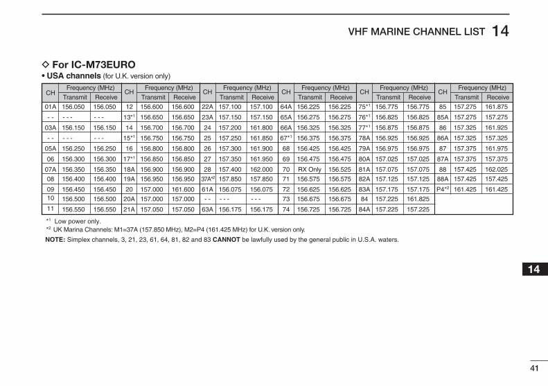
New2001
41
14VHF MARINE CHANNEL LIST
New2001
12345678910111213141516
NOTE: Simplex channels, 3, 21, 23, 61, 64, 81, 82 and 83 CANNOT be lawfully used by the general public in U.S.A. waters.
*1 Low power only. *2 UK Marina Channels: M1=37A (157.850 MHz), M2=P4 (161.425 MHz) for U.K. version only.
• USA channels (for U.K. version only)
Frequency (MHz) Frequency (MHz) Frequency (MHz) Frequency (MHz) Frequency (MHz) Frequency (MHz)
Transmit Receive Transmit Receive Transmit Receive Transmit Receive Transmit Receive Transmit Receive
156.050 156.050 156.600 156.600 157.100 157.100 156.225 156.225 156.775 156.775
156.825 156.825
156.875 156.875 157.325 161.925
- - - - - - 156.650 156.650 157.150 157.150 156.275 156.275
156.925 156.925 157.325 157.325
156.150 156.150 156.700 156.700 157.200 161.800 156.325 156.325
156.975 156.975 157.375 161.975
- - - - - - 156.750 156.750 157.250 161.850 156.375 156.375
157.025 157.025 157.375 157.375
156.250 156.250 156.800 156.800 157.300 161.900 156.425 156.425
157.075 157.075 157.425 162.025
156.300 156.300 156.850 156.850 157.350 161.950 156.475 156.475
157.125 157.125 157.425 157.425
161.425 161.425
156.350 156.350 156.900 156.900 157.400 162.000 RX Only 156.525
157.175 157.175
156.400 156.400 156.950 156.950 157.850 157.850 156.575 156.575
157.225 161.825
156.450 156.450 157.000 161.600 156.075 156.075 156.625 156.625
157.225 157.225
156.500 156.500 157.000 157.000 - - - - - - 156.675 156.675
156.550 156.550 157.050 157.050 156.175 156.175 156.725 156.725
157.275 161.875
157.275 157.275
12
13*1
20A
21A
20
19A
18A
17*1
16
15*1
14
CH
22A
23A
- -
63A
61A
37A*2
28
27
26
25
24
CH
64A
65A
73
74
72
71
70
69
68
67*1
66A
CH
75*1
76*1
84
84A
83A
82A
81A
80A
79A
78A
77*1
CH
85
85A
P4*2
88A
88
87A
87
86A
86
CH
01A
- -
10
11
09
08
07A
06
05A
- -
03A
CH
D For IC-M73EURO
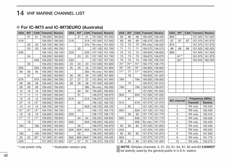
New2001
42
14 VHF MARINE CHANNEL LIST
New2001
NOTE: Simplex channels, 3, 21, 23, 61, 64, 81, 82 and 83 CANNOTbe lawfully used by the general public in U.S.A. waters.
*1 Low power only. *2 Australian version only
Channel number Frequency (MHz)
03 156.150 160.7500303A 156.150 156.150
156.200 160.80004
02 156.100 160.70002
04A 156.200 156.200156.250 160.85005
05A 05A 156.250 156.25006 06 156.300 156.30006
156.350 160.9500707A 07A 156.350 156.35008 08 156.400 156.4000809 09 156.450 156.4500910 10 156.500 156.5001011 11 156.550 156.5501112 12 156.600 156.60012
13*1 13*1 156.650 156.6501314 14 156.700 156.70014
15*1 15*1 156.750 156.75015*1
16 16 156.800 156.8001617*1 17*1 156.850 156.85017
156.900 161.5001818A 18A 156.900 156.900
156.950 161.5501919A 19A 156.950 156.95020 20*1 157.000 161.60020
20A 157.000 157.000
01A 156.050 156.050
USA01 156.050 160.65001
CAN Transmit ReceiveINTChannel number Frequency (MHz)
157.100 161.7002222A 22A 157.100 157.100
23 157.150 161.75023
21b Rx only 161.650
23A 157.150 157.15024 24 157.200 161.8002425 25 157.250 161.85025
25b Rx only 161.85026 26 157.300 161.9002627 27 157.350 161.9502728 28 157.400 162.00028
28b Rx only 162.00060 156.025 160.62560
156.075 160.6756161A 61A 156.075 156.075
156.125 160.7256262A 156.125 156.125
156.175 160.7756363A 156.175 156.175
64 156.225 160.8256464A 64A 156.225 156.225
156.275 160.8756565A 65A 156.275 156.27565A
156.325 160.9256666A 66A*1 156.325 156.32566A67*1 67 156.375 156.37567
21A 21A 157.050 157.050
USA21 157.050 161.65021
CAN Transmit ReceiveINTChannel number Frequency (MHz)
71 71 156.575 156.5757172 72 156.625 156.6257273 73 156.675 156.67573
70 70 RX only 156.52570
74 74 156.725 156.7257475*1 75*1 156.775 156.77575*1
76*1 76*1 156.825 156.82576*1
77*1 77*1 156.875 156.87577156.925 161.52578
78A 78A 156.925 156.925156.975 161.57579
79A 79A 156.975 156.975157.025 161.62580
80A 80A 157.025 157.025157.075 161.67581
81A 81A 157.075 157.075157.125 161.72582
82A 82A 157.125 157.12583 157.175 161.77583
83A 83A 157.175 157.17583b Rx only 161.775
84 84 157.225 161.8258484A 157.225 157.22585 85 157.275 161.87585
85A 157.275 157.27586 86 157.325 161.92586
69 69 156.475 156.4756968
USA68 156.425 156.42568
CAN Transmit ReceiveINTChannel number Frequency (MHz)
88 88 157.425 162.0258888A 157.425 157.425
161.975 161.975A1*2
87A 157.375 157.375
162.025 162.025A2*2
87 87 157.375 161.9758786AUSA
157.325 157.325CAN Transmit ReceiveINT
Frequency (MHz)
RX only 162.425RX only 162.450RX only 162.500
RX only 162.475
RX only 162.525RX only 161.650RX only 161.775RX only 163.275
RX only 162.400RX only 162.550Transmit Receive
WX channel
456
3
78910
21
D For IC-M73 and IC-M73EURO (Australia)
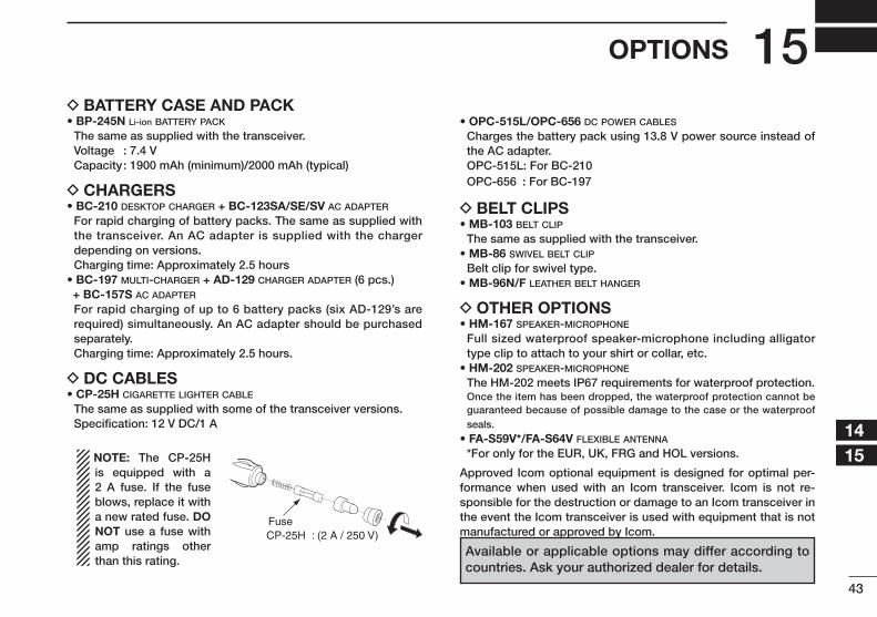
43
15OPTIONS
New2001
12345678910111213141516
D BATTERY CASE AND PACK• BP-245N Li-ion battery pack
The same as supplied with the transceiver. Voltage : 7.4 V Capacity : 1900 mAh (minimum)/2000 mAh (typical)
D CHARGERS• BC-210 desktop charger + BC-123SA/SE/SV ac adapter
For rapid charging of battery packs. The same as supplied with the transceiver. An AC adapter is supplied with the charger depending on versions.
Charging time: Approximately 2.5 hours• BC-197 multi-charger + AD-129 charger adapter (6 pcs.) + BC-157S ac adapter
For rapid charging of up to 6 battery packs (six AD-129’s are required) simultaneously. An AC adapter should be purchased separately.
Charging time: Approximately 2.5 hours.
D DC CABLES• CP-25H cigarette lighter cable
The same as supplied with some of the transceiver versions. Specification: 12 V DC/1 A
NOTE: The CP-25H is equipped with a 2 A fuse. If the fuse blows, replace it with a new rated fuse. DO NOT use a fuse with amp ratings other than this rating.
• OPC-515L/OPC-656 dc power cables
Charges the battery pack using 13.8 V power source instead of the AC adapter.
OPC-515L: For BC-210 OPC-656 : For BC-197
D BELT CLIPS• MB-103 belt clip
The same as supplied with the transceiver.• MB-86 swivel belt clip
Belt clip for swivel type. • MB-96N/F leather belt hanger
D OTHER OPTIONS• HM-167 speaker-microphone
Full sized waterproof speaker-microphone including alligator type clip to attach to your shirt or collar, etc.
• HM-202 speaker-microphone
The HM-202 meets IP67 requirements for waterproof protection. Once the item has been dropped, the waterproof protection cannot be
guaranteed because of possible damage to the case or the waterproof seals.
• FA-S59V*/FA-S64V flexible antenna
*For only for the EUR, UK, FRG and HOL versions.
Approved Icom optional equipment is designed for optimal per-formance when used with an Icom transceiver. Icom is not re-sponsible for the destruction or damage to an Icom transceiver in the event the Icom transceiver is used with equipment that is not manufactured or approved by Icom.
Available or applicable options may differ according to countries. Ask your authorized dealer for details.
CP-25H : (2 A / 250 V) Fuse
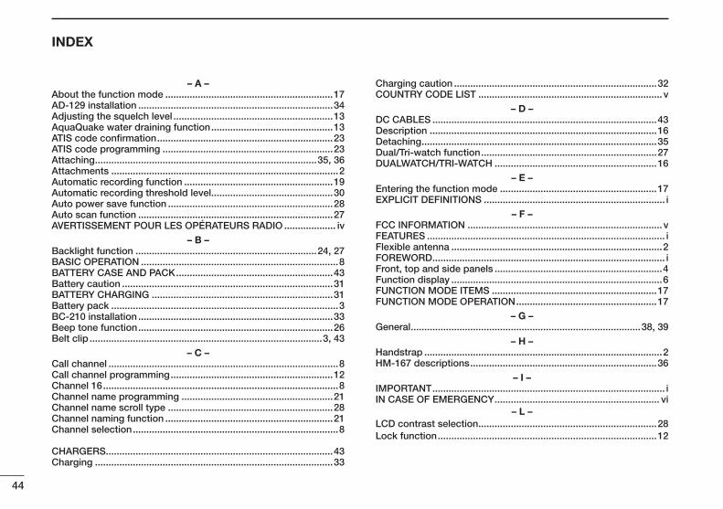
44
INDEX
New2001
– A –About the function mode ..............................................................17AD-129 installation ........................................................................34Adjusting the squelch level ...........................................................13AquaQuake water draining function .............................................13ATIS code confirmation .................................................................23ATIS code programming ...............................................................23Attaching ..................................................................................35, 36Attachments ....................................................................................2Automatic recording function .......................................................19Automatic recording threshold level .............................................30Auto power save function .............................................................28Auto scan function ........................................................................27AVERTISSEMENT POUR LES OPÉRATEURS RADIO ................... iv
– B –Backlight function ...................................................................24, 27BASIC OPERATION .........................................................................8BATTERY CASE AND PACK ..........................................................43Battery caution ..............................................................................31BATTERY CHARGING ...................................................................31Battery pack ....................................................................................3BC-210 installation ........................................................................33Beep tone function ........................................................................26Belt clip ......................................................................................3, 43
– C –Call channel .....................................................................................8Call channel programming ............................................................12Channel 16 .......................................................................................8Channel name programming ........................................................21Channel name scroll type .............................................................28Channel naming function ..............................................................21Channel selection ............................................................................8
CHARGERS ....................................................................................43Charging ........................................................................................33
Charging caution ...........................................................................32COUNTRY CODE LIST .................................................................... v
– D –DC CABLES ...................................................................................43Description ....................................................................................16Detaching .......................................................................................35Dual/Tri-watch function .................................................................27DUALWATCH/TRI-WATCH ............................................................16
– E –Entering the function mode ..........................................................17EXPLICIT DEFINITIONS ................................................................... i
– F –FCC INFORMATION ........................................................................ vFEATURES ........................................................................................ iFlexible antenna ..............................................................................2FOREWORD ...................................................................................... iFront, top and side panels ..............................................................4Function display ..............................................................................6FUNCTION MODE ITEMS .............................................................17FUNCTION MODE OPERATION ....................................................17
– G –General .....................................................................................38, 39
– H –Handstrap ........................................................................................2HM-167 descriptions .....................................................................36
– I –IMPORTANT ...................................................................................... iIN CASE OF EMERGENCY ............................................................. vi
– L –LCD contrast selection ..................................................................28Lock function .................................................................................12
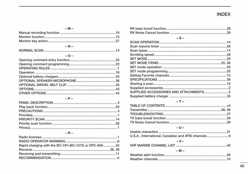
45
INDEX
New2001
12345678910111213141516
– M –Manual recording function ............................................................18Monitor function ............................................................................12Monitor key action .........................................................................27
– N –NORMAL SCAN .............................................................................14
– O –Opening comment entry function .................................................22Opening comment programming ..................................................22OPERATING RULES ........................................................................1Operation .......................................................................................16Optional battery chargers .............................................................34OPTIONAL SPEAKER-MICROPHONE ..........................................36OPTIONAL SWIVEL BELT CLIP.....................................................35OPTIONS ........................................................................................43OTHER OPTIONS ..........................................................................43
– P –PANEL DESCRIPTION .....................................................................4Play back function .........................................................................20PRECAUTIONS ................................................................................ iiPriorities ...........................................................................................1PRIORITY SCAN ............................................................................14Priority scan function ....................................................................26Privacy .............................................................................................1
– R –Radio licenses .................................................................................1RADIO OPERATOR WARNING ....................................................... iiiRapid charging with the BC-197+BC-157S or OPC-656 .............34Receiver ...................................................................................38, 39Receiving and transmitting ...........................................................11RECOMMENDATION ...................................................................... vi
RX bass boost function .................................................................29RX Noise Cancel function .............................................................29
– S –SCAN OPERATION ........................................................................14Scan resume timer ........................................................................26Scan types .....................................................................................14Scrolling speed ..............................................................................28SET MODE .....................................................................................25SET MODE ITEMS ...................................................................25, 26SET mode operation .....................................................................25SET mode programming ...............................................................25Setting Favorite channels .............................................................15SPECIFICATIONS ..........................................................................38Starting a scan ...............................................................................15Supplied accessories ......................................................................2SUPPLIED ACCESSORIES AND ATTACHMENTS ..........................2Supplied battery charger ..............................................................33
– T –TABLE OF CONTENTS .................................................................. viiTransmitter ...............................................................................38, 39TROUBLESHOOTING ....................................................................37TX bass boost function .................................................................29TX Noise Cancel function ..............................................................29
– U –Usable characters .........................................................................21U.S.A., International, Canadian and ATIS channels .......................9
– V –VHF MARINE CHANNEL LIST .......................................................40
– W –Weather alert function ...................................................................26Weather channels ..........................................................................10

46
MEMO
New2001

47
MEMO
New2001
12345678910111213141516
1-1-32 Kamiminami, Hirano-ku, Osaka 547-0003, Japan
A-7070D-1EX-qPrinted in Japan© 2013 Icom Inc.
New2001
< Intended Country of Use >ATFIITPLGBRO
BEFRLVPTISTR
CYDELTSKLIHR
CZGRLUSINO
DKHUMTESCH
EEIENLSEBG
Printed on recycled paper with soy ink.