Pattern Recognition 35 (2002) 627–638www.elsevier.com/locate/patcog
A unifying framework for lossless and progressiveimage coding
Amel Benazza-Benyahiaa, Jean-Christophe Pesquetb; ∗aD�epartement de Math�ematiques Appliqu�ees, Signal et Communications, Ecole Sup�erieure des Communications de Tunis,
Parc Technologique des Communications, Cit�e El Ghazala, 2083, Ariana, TunisiabLaboratoire Syst%emes de Communication, Universit�e de Marne-la-Vall�ee, 5 Boulevard Descartes, Champs sur Marne 77454
Marne la Vall�ee Cedex 2, France
Received 16 November 2000; accepted 16 November 2000
Abstract
Progressive coding is a desirable feature for image database telebrowsing or image transmissions over low bandwidthchannels. Furthermore, for some applications, exact image reconstruction is required. In this paper, we show that mostof the lossless and progressive coders can be described by a common nonlinear subband decomposition scheme. Thisunifying framework provides useful guidelines for the analysis and improvement of the considered decompositionmethods. Finally, we compare the respective performances of these methods in terms of Shannon entropy for severalimages and also evaluate their compression ability when combined with a hierarchical coding technique. ? 2001 PatternRecognition Society. Published by Elsevier Science Ltd. All rights reserved.
Keywords: Lossless image compression; Progressive image reconstruction; Nonlinear decompositions; Subband coding; Wavelets
1. Introduction
As a result of the generalized use of images, there is anincreasing need for e8cient image compression methods.Furthermore, the ability of progressively reconstructingthe images constitutes a useful functionality for compres-sion schemes. Indeed, a single compressed 9le may beshared by several target output devices with di:erent res-olutions. Besides, during an interactive visual search overa large image database, an initial part of the informationallows the receiving device to get a crude approxima-tion of the image. As transmission proceeds, the receivergradually constructs approximations of increased visualquality. If the intermediate displayed image is judged ofno interest, the transmission can be aborted. This results
∗ Corresponding author.E-mail addresses: [email protected] (A. Benazza-
Benyahia), [email protected] (J.-C. Pesquet).
in a gain in terms of bit rate, especially when the userdoes not completely download the image. Multireso-lution decompositions [1] are very compelling toolsfor progressive image coding as they provide hierar-chical representations of images. However, for med-ical imaging or remote sensing, lossless compressionis sometimes required since the least distortion in thereconstructed image can lead to errors in data inter-pretation or diagnosis. In this context, the greatest caremust be taken in order to ensure an exact coding. Thus,the very large amount of data involved in the 9eld ofpicture archiving=transmission systems must be cou-pled with the fact that no distortion is allowed. To thisrespect, since the pioneering works of Burt and Adel-son [2], a certain number of pyramidal decompositionswhich are information preserving, have been proposed.In recent works [3,4], nonlinear multirate 9lter bankswith maximal decimation and perfect reconstructionwere investigated. These 9lter banks are closely related
0031-3203/01/$22.00 ? 2001 Pattern Recognition Society. Published by Elsevier Science Ltd. All rights reserved.PII: S0031-3203(01)00065-6
628 A. Benazza-Benyahia, J.-C. Pesquet / Pattern Recognition 35 (2002) 627–638
to other recent developments concerning the liftingscheme [5,6] and nonlinear multiresolution analyses[7].
Our objective in this study is to show that the analysisscheme described in Ref. [4] provides a unifying frame-work for most of the decompositions proposed until nowin the context of progressive and exact coding. This pa-per is organized as follows. Section 2 describes generalschemes for nonlinear subband decomposition. Section 3allows us to review most of the existing pyramidal codersin terms of such analysis schemes. Sections 3.1 and 3.2are, respectively, devoted to Laplacian-like pyramids andinterpolative pyramids. Section 4 is concerned with non-linear wavelet-like subband decompositions which ap-pear as special cases of the considered decompositionschemes. Finally, Section 6 provides some experimen-tal results in order to compare the performances of thesecoders.
2. Considered decomposition scheme
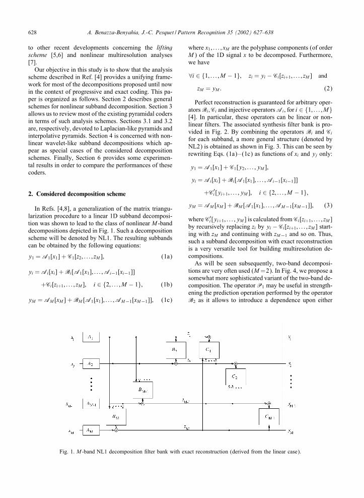
In Refs. [4,8], a generalization of the matrix triangu-larization procedure to a linear 1D subband decomposi-tion was shown to lead to the class of nonlinear M -banddecompositions depicted in Fig. 1. Such a decompositionscheme will be denoted by NL1. The resulting subbandscan be obtained by the following equations:
y1 = A1[x1] + C1[z2; : : : ; zM ]; (1a)
yi = Ai[xi] + Bi[A1[x1]; : : : ;Ai−1[xi−1]]
+Ci[zi+1; : : : ; zM ]; i ∈ {2; : : : ; M − 1}; (1b)
yM = AM [xM ] + BM [A1[x1]; : : : ;AM−1[xM−1]]; (1c)
Fig. 1. M -band NL1 decomposition 9lter bank with exact reconstruction (derived from the linear case).
where x1; : : : ; xM are the polyphase components (of orderM) of the 1D signal x to be decomposed. Furthermore,we have
∀i ∈ {1; : : : ; M − 1}; zi = yi − Ci[zi+1; : : : ; zM ] and
zM = yM : (2)
Perfect reconstruction is guaranteed for arbitrary oper-atorsBi ;Ci and injective operatorsAi, for i ∈ {1; : : : ; M}[4]. In particular, these operators can be linear or non-linear 9lters. The associated synthesis 9lter bank is pro-vided in Fig. 2. By combining the operators Bi and Cifor each subband, a more general structure (denoted byNL2) is obtained as shown in Fig. 3. This can be seen byrewriting Eqs. (1a)–(1c) as functions of xi and yj only:
y1 = A1[x1] + C1[y2; : : : ; yM ];
yi = Ai[xi] + Bi[A1[x1]; : : : ;Ai−1[xi−1]]
+C′i [yi+1; : : : ; yM ]; i ∈ {2; : : : ; M − 1};
yM = AM [xM ] + BM [A1[x1]; : : : ;AM−1[xM−1]]; (3)
whereC′i [yi+1; : : : ; yM ] is calculated fromCi[zi+1; : : : ; zM ]
by recursively replacing zi by yi −Ci[zi+1; : : : ; zM ] start-ing with zM and continuing with zM−1 and so on. Thus,such a subband decomposition with exact reconstructionis a very versatile tool for building multiresolution de-compositions.
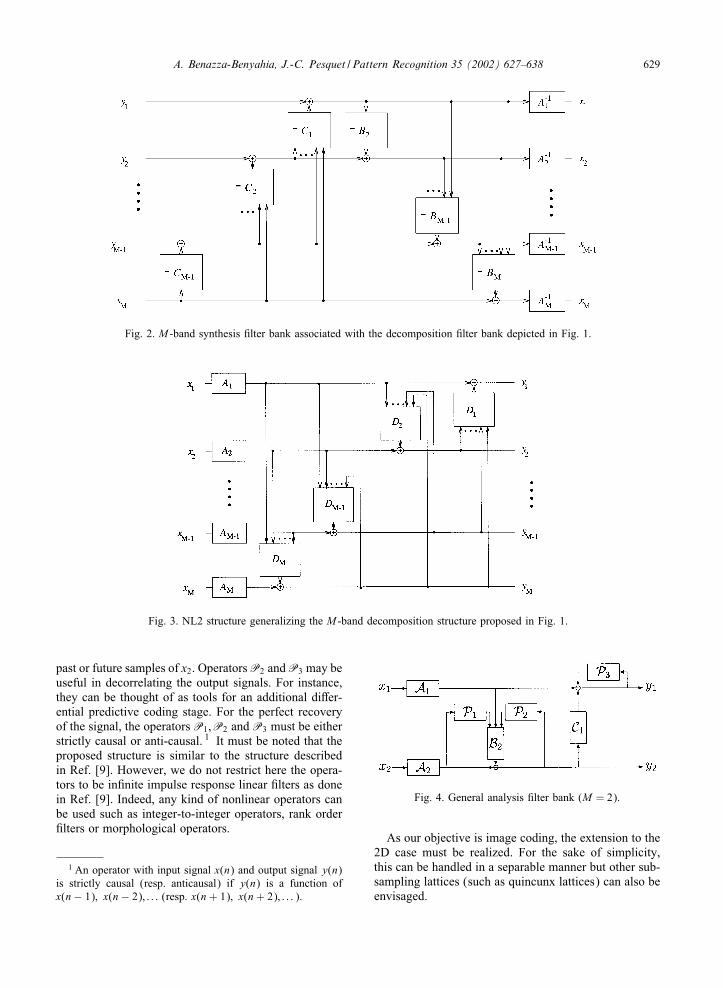
As will be seen subsequently, two-band decomposi-tions are very often used (M=2). In Fig. 4, we propose asomewhat more sophisticated variant of the two-band de-composition. The operator P1 may be useful in strength-ening the prediction operation performed by the operatorB2 as it allows to introduce a dependence upon either
A. Benazza-Benyahia, J.-C. Pesquet / Pattern Recognition 35 (2002) 627–638 629
Fig. 2. M -band synthesis 9lter bank associated with the decomposition 9lter bank depicted in Fig. 1.
Fig. 3. NL2 structure generalizing the M -band decomposition structure proposed in Fig. 1.
past or future samples of x2. Operators P2 and P3 may beuseful in decorrelating the output signals. For instance,they can be thought of as tools for an additional di:er-ential predictive coding stage. For the perfect recoveryof the signal, the operators P1;P2 and P3 must be eitherstrictly causal or anti-causal. 1 It must be noted that theproposed structure is similar to the structure describedin Ref. [9]. However, we do not restrict here the opera-tors to be in9nite impulse response linear 9lters as donein Ref. [9]. Indeed, any kind of nonlinear operators canbe used such as integer-to-integer operators, rank order9lters or morphological operators.
1 An operator with input signal x(n) and output signal y(n)is strictly causal (resp. anticausal) if y(n) is a function ofx(n− 1); x(n− 2); : : : (resp. x(n+ 1); x(n+ 2); : : : ).
Fig. 4. General analysis 9lter bank (M = 2).
As our objective is image coding, the extension to the2D case must be realized. For the sake of simplicity,this can be handled in a separable manner but other sub-sampling lattices (such as quincunx lattices) can also beenvisaged.
630 A. Benazza-Benyahia, J.-C. Pesquet / Pattern Recognition 35 (2002) 627–638
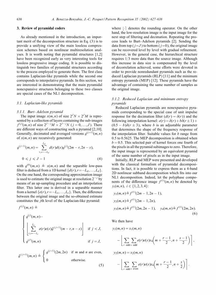
3. Review of pyramidal coders
As already mentioned in the introduction, an impor-tant merit of the decomposition structure in Eq. (3) is toprovide a unifying view of the main lossless compres-sion schemes based on nonlinear multiresolution anal-yses. It is worth noting that pyramidal structures [1,2]have been recognized early as very interesting tools forlossless progressive image coding. It is possible to dis-tinguish two families of pyramidal structures accordingto the process employed to generate them. The 9rst classcontains Laplacian-like pyramids while the second onecorresponds to interpolative pyramids. In this section, weare interested in demonstrating that the main pyramidalnonexpansive structures belonging to these two classesare special cases of the NL1 decomposition.
3.1. Laplacian-like pyramids
3.1.1. Burt–Adelson pyramidThe input image x(m; n) of size 2JN × 2JM is repre-
sented by a collection of layers containing the sub-imagesf(j)(m; n) of size 2J−jM × 2J−jN (j = 0; : : : ; J ). Thereare di:erent ways of constructing such a pyramid [2,10].Generally, decimated and averaged versions g(j+1)(m; n)of x(m; n) are recursively generated:
g(j+1)(m; n) =Ld∑
�; s=−Ldd(r)d(s)g(j)(2m− r; 2n− s);
0 6 j 6 J − 1 (4)
with g(0)(m; n) , x(m; n) and the separable low-pass9lter is deduced from a 1D kernel {d(r); r=−Ld; : : : ; Ld}.On the one hand, the corresponding approximation imageis used to estimate the original image at resolution 2−j bymeans of an up-sampling procedure and an interpolation9lter. This latter one is derived in a separable mannerfrom a kernel {e(r); r=−Le; : : : ; Le}. Then, the di:erencebetween the original image and the so-obtained estimateconstitutes the jth level of the Laplacian-like pyramid:
f(j)(m; n) ,
g(j)(m; n)− Le∑r; s=−Le
e(r)e(s)g ( j+1)(m− r; n− s) if j¡J;
g(J )(m; n) if j = J;
g ( j+1)(m; n) ,
g(j+1)(2m; 2n) if m and n are even;
0 otherwise:(5)
where �· denotes the rounding operator. On the otherhand, the low-resolution image is the input image for thenext step of 9ltering and decimation. Repeating the pro-cess leads to Burt–Adelson pyramids [2]. Sending thedata from top (j=J ) to bottom (j=0), the original imagecan be recovered level by level with gradual re9nement.However, in the general case, the hierarchical structurerequires 1=3 more data than the source image. Althoughthis increase in data size is compensated by the levelof decorrelation achieved, some e:orts were devoted inorder to provide nonredundant pyramids such as the re-duced Laplacian pyramids (RLP) [11] and the minimumentropy pyramids (MEP) [12]. These pyramids have theadvantage of containing the same number of samples asthe original image.
3.1.2. Reduced Laplacian and minimum entropypyramids
Reduced Laplacian pyramids are nonexpansive pyra-mids corresponding to the special case of unit impulseresponse for the decimation 9lter (d(r) = �(r)) and thefollowing interpolation kernel: e(r)=�(r)+b�(r±1)+(0:5 − b)�(r ± 3), where b is an adjustable parameterthat determines the shape of the frequency response ofthe interpolation 9lter. Suitable values for b range from0.5 to 0.5625. The MEP decomposition is obtained whenb= 0:5. This selected pair of kernel forces one fourth ofthe pixels in all the pyramid subimages to zero. Therefore,the input image is represented by an equivalent pyramidof the same number of pixels as in the input image.
Initially, RLP and MEP were presented and developedwith the classical formalism of pyramidal decomposi-tions. In fact, it is possible to express them as a 4-band2D nonlinear subband decomposition which 9ts into ourNL1 decomposition. Indeed, let the polyphase compo-nents of the di:erence image f(1)(m; n) be denoted byyi(m; n); i ∈ {1; 2; 3; 4}:y1(m; n),f
(1)(2m− 1; 2n− 1);
y2(m; n),f(1)(2m− 1; 2n);
y3(m; n),f(1)(2m; 2n− 1); y4(m; n),f
(1)(2m; 2n):(6)
We then have
y1(m; n) = x1(m; n)
−⌊ ∑r odd
∑s odd
e(r)e(s)x4
(m+
r − 12; n+
s− 12
)⌉;
y2(m; n) = x2(m; n)
−⌊ ∑r odd
∑s even
e(r)e(s)x4
(m+
r − 12; n+
s2
)⌉:
A. Benazza-Benyahia, J.-C. Pesquet / Pattern Recognition 35 (2002) 627–638 631
Fig. 5. Arrangement of the input polyphase signals (a), supports of the 9lters calculating y1(m; n) (b), y2(m; n) (c) and y3(m; n)(d). Shaded areas denote non-zero coe8cients, equal gray levels mean identical coe8cient values.
= x2(m; n) −⌊ ∑r odd
e(r)x4
(m+
r − 12; n)⌉
;
y3(m; n)= x3(m; n)
−⌊ ∑r even
∑s odd
e(r)e(s)x4
(m+
r2; n+
s− 12
)⌉
= x3(m; n) −⌊ ∑s odd
e(s)x4
(m; n+
s− 12
)⌉;
y4(m; n) = x4(m; n); (7)
where
x1(m; n),x(2m− 1; 2n− 1) x2(m; n),x(2m− 1; 2n);
x3(m; n),x(2m; 2n− 1) x4(m; n),x(2m; 2n): (8)
The arrangement of the polyphase input componentsas well as the supports for the 9lters are shown in Fig.5. We can see therefore that RLP is a special case ofthe 4-band nonlinear decomposition with perfect recon-struction depicted in Fig. 1 since Ai ; i ∈ {1; 2; 3; 4} be-come the identity operators, B2 = B3 = B4 = 0, and theremaining operators C1;C2 and C3 simplify as they areonly functions of z4 = x4.
3.2. Interpolation pyramidal coders
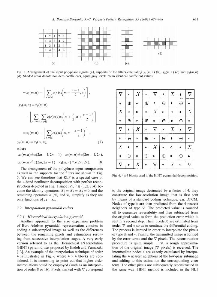
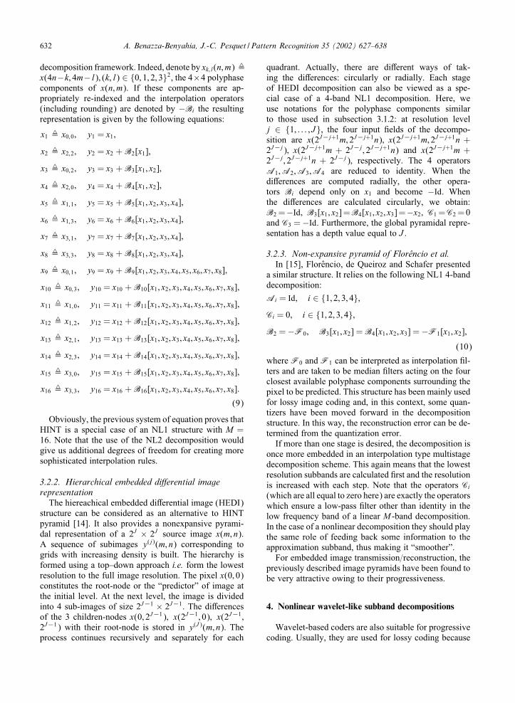
3.2.1. Hierarchical interpolation pyramidAnother approach to the size expansion problem
of Burt–Adelson pyramidal representation consists incoding a sub-sampled image as well as the di:erencesbetween the remaining pixels and estimations result-ing from successive interpolation stages. A very earlyversion referred to as the Hierarchical INTerpolation(HINT) pyramid was proposed by Endoh and Yamazaki[13]. An example of the interpolation technique of order4 is illustrated in Fig. 6 where 4 × 4 blocks are con-sidered. It is interesting to point out that higher orderinterpolations could be employed (such as an interpola-tion of order 8 or 16). Pixels marked with ∇ correspond
Fig. 6. 4×4 blocks used in the HINT pyramidal decomposition.
to the original image decimated by a factor of 4: theyconstitute the low-resolution image that is 9rst sentby means of a standard coding technique, e.g. DPCM.Nodes of type ◦ are then predicted from the 4 nearestneighbors of type ∇. The predicted value is roundedo: to guarantee reversibility and then subtracted fromthe original value to form the prediction error which issent in a second step. Then, pixels X are estimated fromnodes ∇ and ◦ so as to continue the di:erential coding.The process is iterated in order to interpolate the pixelsof type ⊕ and ∗. Finally, the transmitted image is formedby the error terms and the ∇ pixels. The reconstructionprocedure is quite simple. First, a rough approxima-tion of the original image (∇ pixels) is received. Theintermediate nodes ◦ are exactly calculated by interpo-lating the 4 nearest neighbors of the low-pass subimageand adding to this estimation the corresponding errorterm. The other pixels are subsequently reconstructed inthe same way. HINT method is included in the NL1
632 A. Benazza-Benyahia, J.-C. Pesquet / Pattern Recognition 35 (2002) 627–638
decomposition framework. Indeed, denote by xk; l(n; m) ,x(4n−k; 4m−l); (k; l) ∈ {0; 1; 2; 3}2, the 4×4 polyphasecomponents of x(n; m). If these components are ap-propriately re-indexed and the interpolation operators(including rounding) are denoted by −Bi the resultingrepresentation is given by the following equations:
x1 , x0;0; y1 = x1;
x2 , x2;2; y2 = x2 + B2[x1];
x3 , x0;2; y3 = x3 + B3[x1; x2];
x4 , x2;0; y4 = x4 + B4[x1; x2];
x5 , x1;1; y5 = x5 + B5[x1; x2; x3; x4];
x6 , x1;3; y6 = x6 + B6[x1; x2; x3; x4];
x7 , x3;1; y7 = x7 + B7[x1; x2; x3; x4];
x8 , x3;3; y8 = x8 + B8[x1; x2; x3; x4];
x9 , x0;1; y9 = x9 + B9[x1; x2; x3; x4; x5; x6; x7; x8];
x10 , x0;3; y10 = x10 + B10[x1; x2; x3; x4; x5; x6; x7; x8];
x11 , x1;0; y11 = x11 + B11[x1; x2; x3; x4; x5; x6; x7; x8];
x12 , x1;2; y12 = x12 + B12[x1; x2; x3; x4; x5; x6; x7; x8];
x13 , x2;1; y13 = x13 + B13[x1; x2; x3; x4; x5; x6; x7; x8];
x14 , x2;3; y14 = x14 + B14[x1; x2; x3; x4; x5; x6; x7; x8];
x15 , x3;0; y15 = x15 + B15[x1; x2; x3; x4; x5; x6; x7; x8];
x16 , x3;3; y16 = x16 + B16[x1; x2; x3; x4; x5; x6; x7; x8]:
(9)
Obviously, the previous system of equation proves thatHINT is a special case of an NL1 structure with M =16. Note that the use of the NL2 decomposition wouldgive us additional degrees of freedom for creating moresophisticated interpolation rules.
3.2.2. Hierarchical embedded di@erential imagerepresentation
The hiereachical embedded di:erential image (HEDI)structure can be considered as an alternative to HINTpyramid [14]. It also provides a nonexpansive pyrami-dal representation of a 2J × 2J source image x(m; n).A sequence of subimages y(j)(m; n) corresponding togrids with increasing density is built. The hierarchy isformed using a top–down approach i.e. form the lowestresolution to the full image resolution. The pixel x(0; 0)constitutes the root-node or the “predictor” of image atthe initial level. At the next level, the image is dividedinto 4 sub-images of size 2J−1 × 2J−1. The di:erencesof the 3 children-nodes x(0; 2J−1); x(2J−1; 0); x(2J−1;2J−1) with their root-node is stored in y(J )(m; n). Theprocess continues recursively and separately for each
quadrant. Actually, there are di:erent ways of tak-ing the di:erences: circularly or radially. Each stageof HEDI decomposition can also be viewed as a spe-cial case of a 4-band NL1 decomposition. Here, weuse notations for the polyphase components similarto those used in subsection 3:1:2: at resolution levelj ∈ {1; : : : ; J}, the four input 9elds of the decompo-sition are x(2J−j+1m; 2J−j+1n); x(2J−j+1m; 2J−j+1n +2J−j); x(2J−j+1m + 2J−j ; 2J−j+1n) and x(2J−j+1m +2J−j ; 2J−j+1n + 2J−j); respectively. The 4 operatorsA1;A2;A3;A4 are reduced to identity. When thedi:erences are computed radially, the other opera-tors Bi depend only on x1 and become −Id. Whenthe di:erences are calculated circularly, we obtain:B2 =−Id; B3[x1; x2]=B4[x1; x2; x3]=−x2; C1 =C2 =0and C3 = −Id. Furthermore, the global pyramidal repre-sentation has a depth value equal to J .
3.2.3. Non-expansive pyramid of Florencio et al.In [15], Florencio, de Queiroz and Schafer presented
a similar structure. It relies on the following NL1 4-banddecomposition:
Ai = Id; i ∈ {1; 2; 3; 4};Ci = 0; i ∈ {1; 2; 3; 4};B2 = −F0; B3[x1; x2] = B4[x1; x2; x3] = −F1[x1; x2];
(10)
where F0 and F1 can be interpreted as interpolation 9l-ters and are taken to be median 9lters acting on the fourclosest available polyphase components surrounding thepixel to be predicted. This structure has been mainly usedfor lossy image coding and, in this context, some quan-tizers have been moved forward in the decompositionstructure. In this way, the reconstruction error can be de-termined from the quantization error.
If more than one stage is desired, the decomposition isonce more embedded in an interpolation type multistagedecomposition scheme. This again means that the lowestresolution subbands are calculated 9rst and the resolutionis increased with each step. Note that the operators Ci(which are all equal to zero here) are exactly the operatorswhich ensure a low-pass 9lter other than identity in thelow frequency band of a linear M -band decomposition.In the case of a nonlinear decomposition they should playthe same role of feeding back some information to theapproximation subband, thus making it “smoother”.
For embedded image transmission=reconstruction, thepreviously described image pyramids have been found tobe very attractive owing to their progressiveness.
4. Nonlinear wavelet-like subband decompositions
Wavelet-based coders are also suitable for progressivecoding. Usually, they are used for lossy coding because
A. Benazza-Benyahia, J.-C. Pesquet / Pattern Recognition 35 (2002) 627–638 633
the wavelet coe8cients take noninteger values even whenthe input signal is integer valued. So, for lossless andprogressive image coding, it is mandatory to build re-versible wavelet transforms such that a signal with inte-ger coe8cients can be exactly recovered. Subsequently,these decompositions are presented in the 1D case. Theycan be straightforwardly extended to the 2D case in aseparable way.
4.1. Swelden’s lifting scheme
Sweldens [6] has developed the concept of secondgeneration wavelets. The main di:erence of the secondgeneration of wavelets with the conventional one—the9rst generation—is that it does not rely on the Fouriertransform for its construction. Only spatial arguments areused to build such new transforms. The lifting schemecan be decomposed in three basic parts. The 9rst stepconsists in splitting the odd and the even samples x1(n)and x2(n) of the 1D input signal x(n). Then, a decor-relation step between the polyphase signals is carriedout: coe8cients x2(n) are estimated from the neighboringcoe8cients x1(n) by a transversal linear predictor P.Computing the prediction residual corresponds to the 9rstlifting step: y2 = x2 − �P[x1]. The second lifting stepupdates the even samples x1(n) with a linear combina-tion of the prediction results y2(n). A low-pass 9lteredversion y1(n) of x(n) is then obtained: y1 =x1−�U[y2].It is worth pointing out that in the work of Sweldens[15], the operators P and U are restricted to be linear.Several examples of such linear operators have been al-ready tabulated in Ref. [16]. In the following, we willdenote by cN; N the wavelet transforms that map integersto integers where the number N (resp. N ) correspondsto the number of vanishing moments of the analyzing(resp. synthesizing) high-pass 9lters. By varying (N; N ),it is possible to generate a family of reversible wavelettransforms that map integers to integers. Obviously, thisstructure is included in the general scheme NL1 withM = 2; A1 = A2 = Id; B2 = −�P and C1 = �U.
4.2. Morphological subband decomposition
One of the 9rst papers on nonlinear subband decompo-sitions was published in 1995 by Egger et al. from EPFL[17]. They proposed a subband decomposition named“morphological subband decomposition” which amountsto a special case of the 2-band 9lter bank NL1 where A1
andA2 are reduced to identity andC1 is the null operator.The operator B2 could be chosen either as a median 9lteror a linear one. The input polyphase components wereobtained by a particular implementation of rectangularsubsampling. The authors presented their decomposi-tion as a nonlinear 9ltering applied on the entire inputsignal followed by critical subsampling. This may leadto the impression that the decomposition is valid for a
speci9c class of 9lters only. The description of thismethod in terms of nonlinear 9lters operating on thepolyphase components of the input signal leads to a sim-pler implementation. The presented decomposition wascascaded to create a non-separable 2D decompositiondevoted only to lossy image coding applications. Thecase of lossless coding was not addressed. The subbandcoe8cient signals were quantized and entropy coded.
Other interesting morphological subband decomposi-tions which can be included in our framework may befound in Ref. [7].
4.3. S + P transform
Said and Pearlman proposed to complete the S trans-form by an additional predictive step (P) [18]. So, astandard S transform is 9rstly computed:
l(n) = �(x1(n) + x2(n))=2; h(n) = x2(n) − x1(n);(11)
then the 2-band decomposition coe8cients are calculatedusing the following anti-causal prediction algorithm:
y1(n) = l(n);
y2(n) = h(n)
− L1∑k=−L0
�1(l(n+k−1)−l(n+k))−H∑l=1
!lh(n+l)
⌉:
(12)
For standard natural images the following parameters areused: "i= 2
8�(i)+38�(i−1); !i= 2
8�(i−1). The predictionequations in Eq. (12) do not 9t into the NL1 structuredepicted in Fig. 1 because of the recursive term on h(n).However, they are compatible with the scheme shown inFig. 4 with an anticausal recursive part in the P1 operator(P2 = P3 = C1 = 0).
4.4. Proposed nonlinear subband decomposition
Fig. 4 gives us insight for designing new subbanddecompositions. For example, we propose to comparethe previously described techniques with a 2-band gen-eralized decomposition which will be designated byT("; !)(("; !) ∈ R2). A relatively generic 4 tap interpo-lation 9lter can be envisaged for the “prediction” step:
x(2n) ="2(x(2n− 1) + x(2n+ 1)) +
1 − "2
(x(2n− 2)
+x(2n+ 2)): (13)
Unfortunately, we are not allowed to use both a causalterm (x(2n − 2)) and an anticausal one (x(2n + 2))in the P1 operator in Fig. 4. To circumvent this dif-9culty, we replace x(2n + 2) by (x(2n + 1) + x(2n +3))=2 in (13). By adding the required rounding operation,
634 A. Benazza-Benyahia, J.-C. Pesquet / Pattern Recognition 35 (2002) 627–638
we obtain:
y2(n) = x2(n) −⌊"2x1(n) +
1 + "4
x1(n+ 1)
+1 − "
2x2(n− 1) +
1 − "4
x1(n+ 2)⌉
(14)
where x1(n) = x(2n− 1) and x2(n) = x(2n). For the “up-date” term (operator C1), we simply use
y1(n) = x1(n) + �!(y2(n) + y2(n− 1)): (15)
The parameter " can be related to the parameter !. In-deed, if we omit the rounding operations, the update op-erator corresponding to (15) should be a low-pass 9lterfollowed by a decimation stage. Therefore, the frequencyresponse of this 9lter should be equal to zero at the fre-quency 1=2. After some simple calculations, we 9nd thatthe following condition must be satis9ed:
!=1
2("+ 1): (16)
This means that it is more appropriate to consider thenonlinear decomposition T("; !) as a decomposition witha single parameter. For the sake of simplicity, this decom-position will be denoted by T("). The parameter " canbe optimized numerically in order to achieve a minimumentropy for the resulting hierarchical representation.
Besides, we note that the special case " = 1 corre-sponds to the decomposition c2;2. If " �= 1; we see thata kind of recursivity is introduced during the predictionstep, described by Eq. (14). As the S+P transform, theresulting decomposition 9ts into the structure describedin Fig. 4 with A1 = A2 = 1d and P2 = P3 = 0.
5. Experimental results
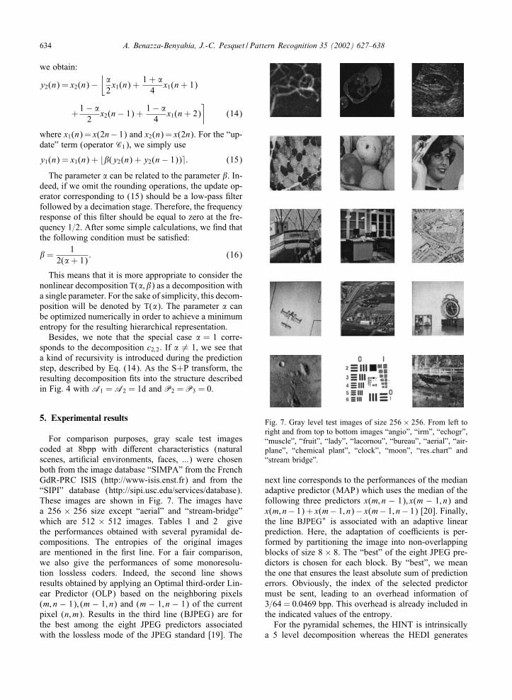
For comparison purposes, gray scale test imagescoded at 8bpp with di:erent characteristics (naturalscenes, arti9cial environments, faces, ...) were chosenboth from the image database “SIMPA” from the FrenchGdR-PRC ISIS (http://www-isis.enst.fr) and from the“SIPI” database (http://sipi.usc.edu/services/database).These images are shown in Fig. 7. The images havea 256 × 256 size except “aerial” and “stream-bridge”which are 512 × 512 images. Tables 1 and 2 givethe performances obtained with several pyramidal de-compositions. The entropies of the original imagesare mentioned in the 9rst line. For a fair comparison,we also give the performances of some monoresolu-tion lossless coders. Indeed, the second line showsresults obtained by applying an Optimal third-order Lin-ear Predictor (OLP) based on the neighboring pixels(m; n − 1); (m − 1; n) and (m − 1; n − 1) of the currentpixel (n; m). Results in the third line (BJPEG) are forthe best among the eight JPEG predictors associatedwith the lossless mode of the JPEG standard [19]. The
Fig. 7. Gray level test images of size 256 × 256. From left toright and from top to bottom images “angio”, “irm”, “echogr”,“muscle”, “fruit”, “lady”, “lacornou”, “bureau”, “aerial”, “air-plane”, “chemical plant”, “clock”, “moon”, “res chart” and“stream bridge”.
next line corresponds to the performances of the medianadaptive predictor (MAP) which uses the median of thefollowing three predictors x(m; n − 1); x(m − 1; n) andx(m; n− 1) + x(m− 1; n)− x(m− 1; n− 1) [20]. Finally,the line BJPEG∗ is associated with an adaptive linearprediction. Here, the adaptation of coe8cients is per-formed by partitioning the image into non-overlappingblocks of size 8 × 8. The “best” of the eight JPEG pre-dictors is chosen for each block. By “best”, we meanthe one that ensures the least absolute sum of predictionerrors. Obviously, the index of the selected predictormust be sent, leading to an overhead information of3=64 = 0:0469 bpp. This overhead is already included inthe indicated values of the entropy.
For the pyramidal schemes, the HINT is intrinsicallya 5 level decomposition whereas the HEDI generates
A. Benazza-Benyahia, J.-C. Pesquet / Pattern Recognition 35 (2002) 627–638 635
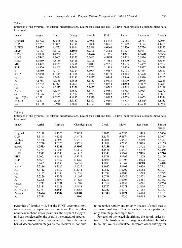
Table 1Entropies of the pyramids for di:erent transformations. Except for HEDI and HINT, 4-level multiresolution decompositions havebeen used
Image Angio Irm Echogr Muscle Fruit Lady Lacornou Bureau
Original 6.1702 5.4578 5.5732 7.4078 5.5745 7.2158 7.5747 6.9054OLP 4.5731 4.5065 4.9398 5.2800 5.0541 5.1529 5.1174 4.1409BJPEG 3.9627 4.4755 4.1804 5.3548 4.0061 5.1550 5.2726 4.1242MAP 4.3133 4.6102 4.1090 5.2378 4.2952 5.1827 5.0641 3.8892BJPEG∗ 4.1008 4.4752 4.9429 5.1676 4.1395 5.0221 4.9670 3.8554HINT 4.5342 4.3602 5.1353 5.2492 4.5459 5.0508 5.0936 4.2723HEDI 5.1659 4.8739 5.1426 6.0398 4.7368 5.6590 5.9762 3.8554MEP 4.6472 4.4337 5.2486 5.4013 4.9695 5.8693 5.2459 4.6702RLP 4.6956 4.4563 5.2028 5.3753 5.1489 5.0559 5.1927 4.7439S 4.6550 4.4797 5.2324 5.6074 4.9367 5.2198 5.4434 4.5813S + P 4.5850 4.3519 4.8206 5.1344 5.0639 4.8843 4.9678 4.3155c2;4 4.5684 4.3424 4.9180 5.1827 5.0344 4.8846 4.9910 4.2267c4;2 4.5758 4.3388 4.7618 5.1152 5.0313 4.8379 4.8976 4.2549c4;4 4.5732 4.3297 4.7664 5.1239 5.0254 4.8283 4.9009 4.2611c6;2 4.6164 4.3577 4.7558 5.1437 5.0592 4.8568 4.9088 4.3199c2+2;2 4.5737 4.3374 4.7632 5.1194 5.0361 4.8513 4.9024 4.2572c9;7 4.6196 4.3379 4.8502 5.1941 5.0362 4.8392 4.9684 4.3863c2;2 = T (1) 4.5511 4.3352 4.8897 5.1529 5.0197 4.8753 4.9653 4.1976T ("opt) 4.5471 4.3326 4.7147 5.0801 5.0191 4.8595 4.8845 4.1883"opt 1.0100 0.9910 1.3600 1.2174 1.0401 1.1533 1.2600 1.0900
Table 2Entropies of the pyramids for di:erent transformations. Except for HEDI and HINT, 4-level multiresolution decompositions havebeen used
Image Aerial Airplane Chemical plant Clock Moon Res-chart Streambridge
Original 5.3148 6.4523 7.3424 6.7057 6.7093 1.5483 5.7056OLP 5.3148 3.8245 5.3471 4.1571 5.0174 2.0740 5.7997BJPEG 5.4488 3.6690 5.5646 4.2078 5.0434 1.5709 4.4553MAP 5.3220 3.6123 5.3628 4.0008 5.2255 1.3916 4.3165BJPEG∗ 4.2553 3.5268 5.3107 3.9239 5.0819 1.5952 5.5154HINT 5.2734 3.6000 5.5119 4.1586 5.0634 4.5239 5.1850HEDI 6.1312 4.1583 6.1413 4.7343 5.5547 1.9126 4.9214MEP 5.5005 3.6683 5.5515 4.2799 5.0992 2.2179 5.6126RLP 5.4664 3.6939 5.4980 4.3079 5.1306 3.0322 5.9323S 5.7409 3.7639 5.6558 4.2883 5.1947 2.0589 5.4048S + P 5.2216 3.5525 5.2037 4.1087 5.0103 2.9830 5.7545c2;4 5.3112 3.5137 5.2941 4.0522 5.0202 2.8982 5.7527c4;2 5.2127 3.5138 5.1638 4.0792 5.0102 3.3203 5.7279c4;4 5.2229 3.5078 5.1697 4.0799 5.0045 3.3971 5.7280c6;2 5.2296 3.5593 5.1526 4.1291 5.0306 3.5561 5.7482c2+2;2 5.2213 3.5191 5.1689 4.0564 5.0132 3.4261 5.2764c9;7 5.3111 3.6128 5.2488 4.1727 5.0071 3.5110 5.7701c2;2 = T (1) 5.2737 3.4944 5.2668 4.0343 5.0079 2.7053 5.7333T ("opt) 5.1624 3.4944 5.0984 4.0343 5.0071 2.6900 5.7185"opt 1.2838 1 1.3800 1 1.0730 0.9985 1.1200
pyramids of depth J = 8. For the HINT decomposition,we use a median operator as a predictor. For the othernonlinear subband decompositions, the depth of the pyra-mid can be selected by the user. In the context of progres-sive transmission, it is recommended to limit the num-ber of decomposition stages as the receiver is not able
to recognize rapidly and reliably images of small size ata coarse resolution. Thus, on each image, we performedonly four-stage decompositions.
For each of the tested algorithms, the zeroth-order en-tropy of the lossless coded image is calculated. In orderto do this, we 9rst calculate the zeroth-order entropy for

636 A. Benazza-Benyahia, J.-C. Pesquet / Pattern Recognition 35 (2002) 627–638
the combined detail images at a given resolution. The en-tropy H of the subband coe8cients is then calculated asthe weighted sum of the entropies of the approximationand the detail sub-images. For a J level decomposition,the global entropy H is given by
H = 2−2JH (AJ ) + 3J∑j=1
2−2jH (Dj); (17)
where Dj denotes the detail subbands at decompositionlevel j, and AJ denotes the approximation subband atlevel J .
The RLP is performed by setting b=0:5. Empirically,this value was found to provide the most compact repre-sentation for RLP. For decomposition T("), the value of" has been optimized for each of the considered imageso as to minimize the entropy. This optimization of a sin-gle parameter function may be realized by an exhaustivesearch algorithm. The optimal value "opt is indicated forcompleteness.
As a visual aid in examining Tables 1 and 2, thebest results within the classes of progressive and nonpro-gressive methods have been highlighted for each image.Some conclusions can be drawn from these results. Firstof all, HEDI method generally leads to the worst per-formances (except for “res-chart” and “stream bridge”).For the majority of the images, HINT method generates5 level representations which are less compact than the4 level ones obtained with the other techniques. How-ever, there are two exceptions (“angio” and “fruit” im-ages). These two results are more related to the meritsof the decomposition itself than the number of decom-position stages used. Indeed, for a 5 stage decomposi-tion, two of the other most e:ective transformations (c2;2for “angio” and S transform for “fruit”) provide entropyvalues (4.6091 and 4.9933) greater than those obtainedwith the HINT method (4.5342 and 4.5459).
The S+P algorithm outperforms the S transform ex-cept in the cases of the “fruit”, “res-chart” and “streambridge” images. We note in particular the surprisinglylow entropy obtained for the “fruit” example with the Stransform. This can be explained by the fact that the orig-inal entropy of this image is quite low as well. This lowvalue is preserved by the S algorithm which performsan updating stage restricted to a multiplicative factor inorder to generate the lowest resolution sub-image.
Another salient point is that there is no single trans-form that performs best over the whole test database.Among multiresolution approaches, the decompositionT("opt) often leads to the most important decrease of theentropy but in several cases, it is outperformed by someother decompositions. In fact, the best transform for eachimage strongly depends on the characteristics of the im-age as reported in Ref. [21]. Note also that the di:erencebetween T("opt) and cN; N transforms is not always im-portant. Furthermore, even if multiresolution approaches
Fig. 8. Image “lacornou” 256×256; approximation sub-imagesat the second level for respectively (from left to right andfrom top to bottom), MEP, S, S + P and T("opt)("opt = 1:26)transforms.
do not always give better results than monoresolutioncoders, the latter ones do not o:er features for progres-sive transmission.
Finally, it is worth noting that a comparison based onlyon the entropies is questionable. First, in a progressivetransmission context, the visual “quality” of the approx-imation sub-images must be taken into account as it isdependent on the decomposition scheme. MEP and RLPgenerate identical low-resolution sub-images which arejust subsampled versions of the input image. The other al-gorithms have more sophisticated interpolation schemes.For illustration, in Fig. 8, the approximation sub-imageat the second level are shown for the “lacornou” image.It can be seen that the artifacts are quite important forthe MEP (and RLP) decompositions, since no 9lteringprior to subsampling is performed for the approximationband. The S and S+P transforms provide quite a smoothimage, which gives a slightly blurred impression, whilethe proposed nonlinear decompositions lead to a slightlysharper result.
Secondly, for real compression schemes, entropycoders must be applied to the resulting hierarchical
A. Benazza-Benyahia, J.-C. Pesquet / Pattern Recognition 35 (2002) 627–638 637
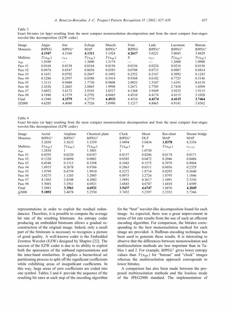
Table 3Exact bit-rates (in bpp) resulting from the most compact monoresolution decomposition and from the most compact four-stageswavelet-like decomposition (EZW coder)
Image Angio Irm Echogr Muscle Fruit Lady Lacornou BureauMonores. BJPEG BJPEG∗ MAP BJPEG∗ BJPEG BJPEG∗ BJPEG∗ BJPEG∗
4.1547 4.5160 4.1311 5.1924 4.2617 5.0221 5.0045 3.8829Multires. T ("opt) c4;4 T ("opt) T ("opt) S c4;4 T ("opt) T ("opt)"opt 1.0100 — 1.3600 1.2174 — — 1.2600 1.0900Pass #1 0.0168 0.0158 0.0164 0.0156 0.0156 0.0224 0.0216 0.0156Pass #2 0.0474 0.0347 0.0656 0.0383 0.0708 0.0713 0.0887 0.0414Pass #3 0.1651 0.0792 0.2847 0.1092 0.2552 0.2167 0.3092 0.1243Pass #4 0.5286 0.2597 0.8588 0.3414 0.9368 0.6182 0.7725 0.3146Pass #5 1.3113 0.9480 1.7730 0.9808 2.0832 1.5347 1.6191 0.6110Pass #6 2.4326 2.2665 2.8865 1.9998 3.2671 2.7705 2.7438 1.0509Pass #7 3.6052 3.6172 3.9103 3.0517 4.1368 3.9569 3.9235 1.9115Pass #8 4.1940 4.1579 4.2792 4.0445 4.4510 4.4174 4.4115 3.1028Final 4.1940 4.1579 4.2779 4.4933 4.4510 4.4174 4.4115 3.7464JJ2000 4.6285 4.4048 4.7526 5.0990 5.1217 4.8865 4.9141 3.8562
Table 4Exact bit-rates (in bpp) resulting from the most compact monoresolution decomposition and from the most compact four-stageswavelet-like decomposition (EZW coder)
Image Aerial Airplane Chemical plant Clock Moon Res-chart Stream bridgeMonores. BJPEG∗ BJPEG∗ BJPEG∗ BJPEG∗ OLP MAP MAP
5.2850 3.5633 5.3359 3.9494 5.0434 1.8378 4.3356Multires. T ("opt) T ("opt) T ("opt) T ("opt) S T ("opt) c2+2;2"opt 1.2838 1 1.3801 1 1.0730 — —Pass #1 0.0295 0.0220 0.0187 0.0157 0.0206 0.0174 0.0171Pass #2 0.1320 0.0694 0.0801 0.0385 0.0472 0.2046 0.0486Pass #3 0.4548 0.1513 0.3398 0.1043 0.1575 0.3979 0.0964Pass #4 1.0915 0.2678 0.9766 0.2863 0.6511 0.6056 0.2329Pass #5 1.9799 0.4759 1.9910 0.5272 1.8714 0.8295 0.5640Pass #6 3.0275 1.1203 3.2005 0.8975 3.2726 1.0793 1.1846Pass #7 4.1303 2.4108 4.3082 1.5891 4.3617 1.3491 2.3356Pass #8 5.5083 3.3561 4.6921 2.6843 4.6747 1.6418 3.6509Final 5.5083 3.3561 4.6921 3.5437 4.6747 1.8476 4.2045jj2000 5.1892 3.4078 5.2550 3.7452 5.2397 2.2352 5.7366
representations in order to exploit the residual redun-dancies. Therefore, it is possible to compute the averagebit rate of the resulting bitstream. An entropy coderproducing an embedded bitstream allows a gradual re-construction of the original image. Indeed, only a smallpart of the bitstream is necessary to recognize a pictureof good quality. A well-known coder is the EmbeddedZerotree Wavelet (EZW) designed by Shapiro [22]. Thesuccess of the EZW coder is due to its ability to exploitboth the sparseness of the subband representations andthe inter-band similarities. It applies a hierarchical setpartitioning process to split o: the signi9cant coe8cientswhile exhibiting areas of insigni9cant coe8cients. Inthis way, large areas of zero coe8cients are coded intoone symbol. Tables 3 and 4 provide the sequence of theresulting bit rates at each step of the encoding algorithm
for the “best” wavelet-like decomposition found for eachimage. As expected, there was a great improvement interms of bit rate results from the use of such an e8cientencoding algorithm. For comparison, the bitrates corre-sponding to the best monoresolution method for eachimage are provided. A Hu:man encoding technique hasbeen used to generate these results. It is interesting toobserve that the di:erences between monoresolution andmultiresolution methods are less important than in Ta-bles 1 and 2. For example, BJPEG∗ gives lower entropyvalues than T ("opt) for “bureau” and “clock” imageswhereas the multiresolution approach corresponds tolower bitrates.
A comparison has also been made between the pro-posed multiresolution methods and the lossless modeof the JPEG2000 standard. The implementation of
638 A. Benazza-Benyahia, J.-C. Pesquet / Pattern Recognition 35 (2002) 627–638
JPEG2000 found at http://jj2000.epT.fr has been used forthis purpose. It turns out that, in most cases, the T ("opt)decomposition combined with EZW coding results in ahigher compression ratio.
6. Conclusions
In this paper, we have emphasized the primary roleplayed by nonlinear subband decomposition structuresfor lossless image compression. The proposed frameworknot only provides a unifying view of existing methodsbut also allows the design of more e8cient compressionalgorithms. In particular, the results shown in Tables 3and 4 are quite encouraging. In our future work, we planto extend these ideas to the compression of multispectralimages.
References
[1] K. Knowlton, Progressive transmission of grey-scale andbinary pictures by simple, e8cient, and lossless encodingschemes, Proc. IEEE 68 (7) (1980) 885–896.
[2] P.J. Burt, E.H. Adelson, The Laplacian pyramid as acompact image code, IEEE Trans. Commun. 31 (4) (1983)532–540.
[3] F.J. Hampson, J.-C. Pesquet, A nonlinear subband decom-position with perfect reconstruction, IEEE InternationalConference on Acoustics, Speech and Signal Processing,Atlanta, GA, USA, May 7–9, 1996, pp. III.1523–III.1526.
[4] F.J. Hampson, J.-C. Pesquet, M -band nonlinear subbanddecompositions with perfect reconstruction, IEEE Trans.Image Process. 7 (11) (1998) 1547–1560.
[5] F.A.M.L. Bruekers, A.W.M. van den Emden, NewNetworks for perfect inversion and perfect reconstruction,IEEE J. Sel. Areas Commun. 10 (1) (1992) 130–137.
[6] W. Sweldens, The Lifting scheme: a new philosophy inbiorthogonal wavelet constructions, Proceedings of SPIE,San-Diego, CA, USA, 2569, September 1995, pp. 68–79.
[7] H.J.A.M. Heijmans, J. Goutsias, Multiresolution signaldecomposition schemes. Part 2: morphological wavelets,IEEE Trans. Image Process. 9 (11) (2000) 1897–1913.
[8] F.J. Hampson, MVethodes non linVeaires en codage d’imageset estimation de mouvement, ThXese de Doctorat del’UniversitVe Paris XI Orsay, July, 1997.
[9] M.D. Adams, Reversible wavelet transforms and theirapplications to embedded image compression, Master ofApplied Science, ECE Department, University of Victoria,BC, Canada, 1998.
[10] L. Wang, M. Goldberg, Comparative performance ofpyramid data structures for progressive image trans-mission, IEEE Trans. Commun. 39 (4) (1991) 504–548.
[11] B. Aiazzi, L. Alparone, S. Baronti, A ReducedLaplacian pyramid for lossless and progressive imagecommunication, IEEE Trans. Commun. 44 (1) (1996)18–22.
[12] D. Houlding, J. Vaisey, Low entropy image pyramids fore8cient lossless coding, IEEE Trans. Image Process. 4(8) (1995) 1150–1153.
[13] T. Endoh, Y. Yamazaki, Progressive coding scheme formulti-level images, Proceedings of the Picture CodingSymposium, Tokyo, Japan, 1986, pp. 21–24.
[14] W. Kim, P.T. Balsar, D.T. Harper, J.W. Park, Hierarchyembedded di:erential image for progressive transmissionusing lossless compression, IEEE Trans. Circuits SystemsVideo Technol. 5 (1) (1995) 1–12.
[15] R.L. Queiroz, D.A. Florencio, R. Schafer, Nonexpansivepyramid for image coding using a nonlinear 9lter bank,IEEE Trans. Image Process. 7 (2) (1998) 246–252.
[16] A.R. Calderbank, I. Daubechies, W. Sweldens, B.-L. Yeo,Wavelet transforms that map intergers to integers, Appl.Comput. Harmonic Anal. 5 (3) (1998) 332–369.
[17] O. Egger, W. Li, M. Kunt, High compression image codingusing an adaptive morphological subband decomposition,Proc. IEEE 83 (2) (1995) 272–287.
[18] A. Said, W.A. Pearlman, An image multiresolutionrepresentation for lossless and lossy compression, IEEETrans. Image Process. 5 (9) (1996) 1303–1310.
[19] JPEG, ISO=IEC 10918-1: Information technology—digitalcompression and coding of continuous-tone still images:requirements and guidelines, 1994.
[20] S.A. Martucci, Reversible compression of HDTV imagesusing median adaptive prediction and arithmetic Coding,IEEE International Symposium on Circuits and Systems,New-Orleans, LA, USA, 1990, pp. 1310–1313.
[21] M.D. Adams, A. Antoniou, Reversible EZW-bases imagecompression using best transform selection and selectivepartial embedding, IEEE Trans. Circuits Systems, Part II47 (10) 1119–1122.
[22] J.M. Shapiro, Embedded image coding using zerotrees ofwavelet coe8cients, IEEE Trans. Signal Process. 41 (12)(1993) 3445–3462.
About the Author—AMEL BENAZZA received her engineering degree from the National Institute of Telecommunications, Evry,France, in 1988 and DEA and Doctorat degrees in signal processing and control from the University of Paris-Sud, France in 1989and 1993, respectively. In 1993, she joined the Ecole SupVerieure des Communications, Tunis, Tunisia where she is currently anassistant Professor at the Department of Mathematics, Signal Processing and Communications. Her research interest include losslessand progressive image compression, signal denoising and medical image analysis.
About the Author—JEAN-CHRISTOPHE PESQUET received his engineering degree from SupVelec, Gif-sur-Yvette, France, in1987, and Doctorat degree from the UniversitVe Paris-Sud (XI), France, in 1990. He received the Habilitation Xa Diriger des Recherchesfrom the UniversitVe Paris-Sud, France, in 1999. From 1991 to 1999, he was a Ma[tre de ConfVerences at the UniversitVe Paris-Sud,and a Research Scientist at the Laboratoire des Signaux et SystXemes, Centre National de la Recherche Scienti9que (CNRS), Paris.He is currently Professor at the UniversitVe de Marne-la-VallVee, France.
Recommended


![VDO Autodiagnos Check - updates.omitec.com€¦ · AUDI A3 Convertible 2008 - 2013 Service Instruments calibration reset[07] Coding,[10] Adaptation,[11] Login / Coding II,[16] Security](https://img.pdfslide.fr/doc/110x75/6124457f674491392823157a/vdo-autodiagnos-check-audi-a3-convertible-2008-2013-service-instruments-calibration.jpg)