Chapter 2, Modeling with UML, Part 1
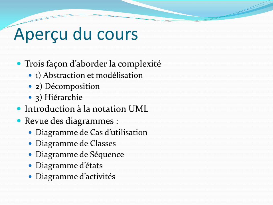
Aperçu du cours Trois façon d’aborder la complexité
1) Abstraction et modélisation 2) Décomposition 3) Hiérarchie
Introduction à la notation UML Revue des diagrammes :
Diagramme de Cas d’utilisation Diagramme de Classes Diagramme de Séquence Diagramme d’états Diagramme d’activités
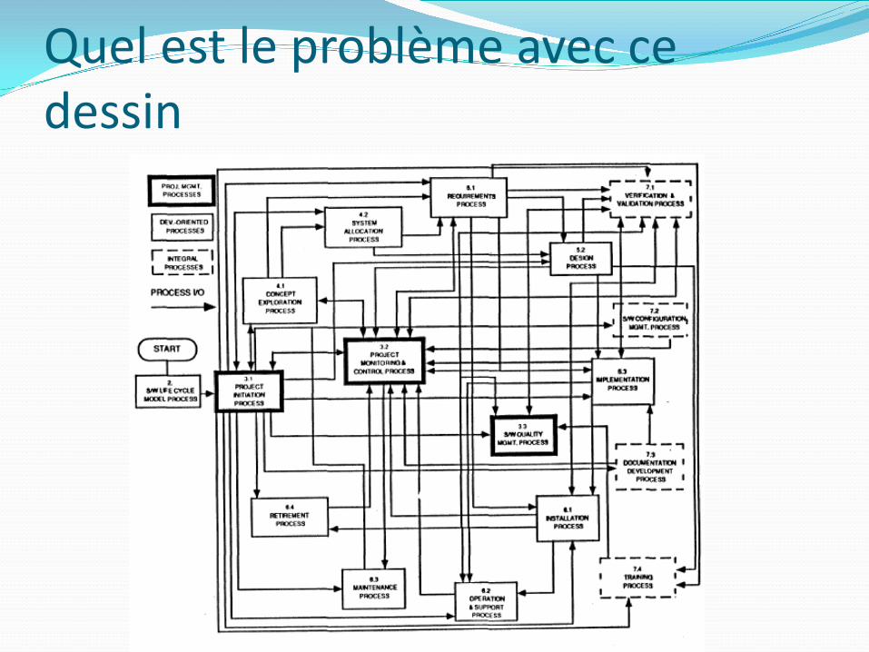
Quel est le problème avec ce dessin
Gérer la complexité : 1) Abstraction
• Les systèmes complexe sont difficile à comprendre • Le phénomème 7 + 2
• Notre mémoire à court terme ne peut pas stocker plus de 7 +- 2 pieces en même temps => limitation du cerveau
• Mon numero de tel est: 498928918204
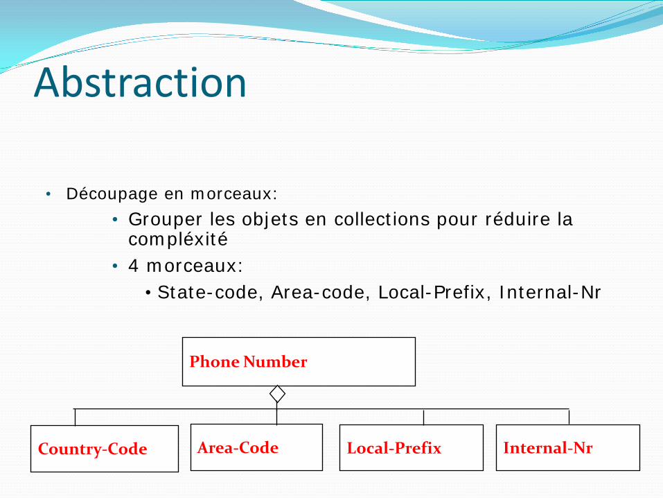
Abstraction
Phone Number
Country-Code Area-Code Local-Prefix Internal-Nr
• Découpage en morceaux: • Grouper les objets en collections pour réduire la
compléxité • 4 morceaux:
• State-code, Area-code, Local-Prefix, Internal-Nr
Abstraction • L’abstraction permet d’ignorer les détails non essentiels • Deux définitions pour l’abstraction :
• L'abstraction est un processus de pensée dans lequel l’idée s’éloigne des objets
• Abstraction comme activité • L’abstraction est l'idée résultant d'un processus de
pensée dans lequel l’idée s’est éloignée d'un objet • Abstraction en tant qu'entité
• Les idées peuvent être exprimées par des modèles
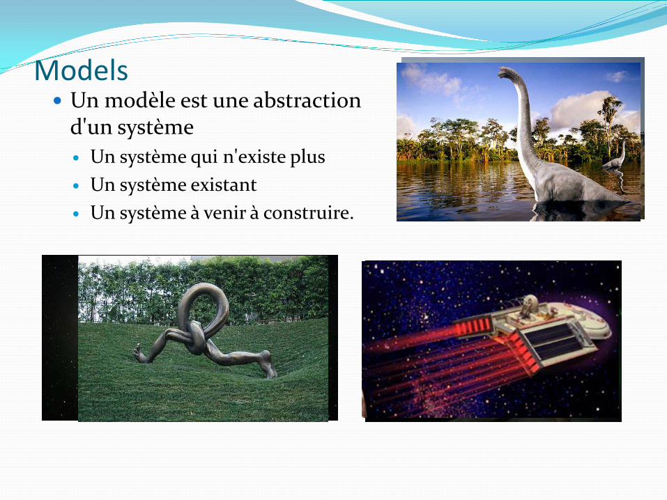
Models Un modèle est une abstraction
d'un système Un système qui n'existe plus Un système existant Un système à venir à construire.
Gérer la complexité : 2) Décomposition Une technique utilisée pour maîtriser la
complexité (“divide and conquer”)
Deux grands types de décomposition Décomposition fonctionnelle Décomposition orientée objet
Décomposition fonctionnelle Le système est décomposé en modules Chaque module est une fonction importante dans
le domaine d'application Les modules peuvent être décomposées en
modules plus petits.
Decomposition (cont’d) Décomposition orientée objet
Le système est décomposé en classes (“objects”) Chaque classe est une entité majeur dans le
domaine d'application Les classes peuvent être décomposés en plus petites
classes
Décomposition orientée objet vs fonctionnel
Quelle décomposition est la bonne?
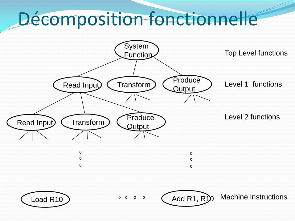
Décomposition fonctionnelle Top Level functions
Level 1 functions
Level 2 functions
Machine instructions
System Function
Load R10 Add R1, R10
Read Input Transform Produce Output
Transform Produce Output Read Input
Décomposition fonctionnelle La fonctionnalité est répartie sur tout le système Il faut comprendre l'ensemble du système pour faire un seul
changement sur le système Conséquence:
Le code source est difficile à comprendre Le code source est complexe et impossible à maintenir L'interface utilisateur est souvent maladroite et non-intuitif.
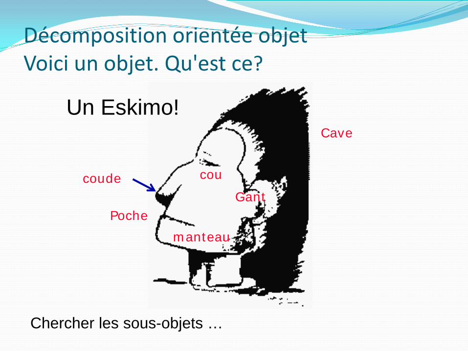
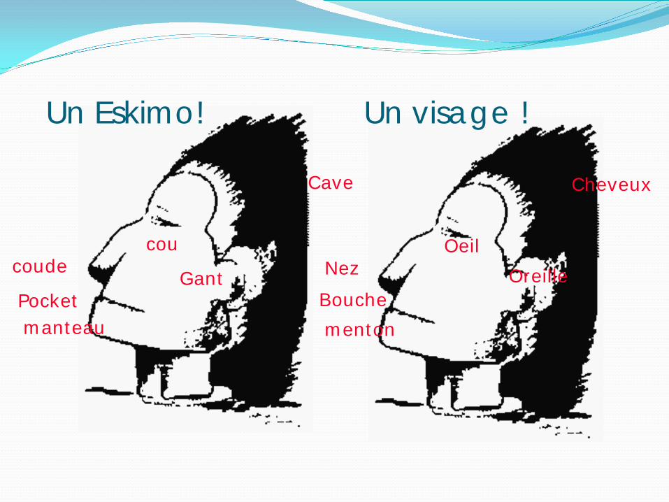
Décomposition orientée objet Voici un objet. Qu'est ce?
cou
Gant
manteau Poche
Cave
coude
Un Eskimo!
Chercher les sous-objets …
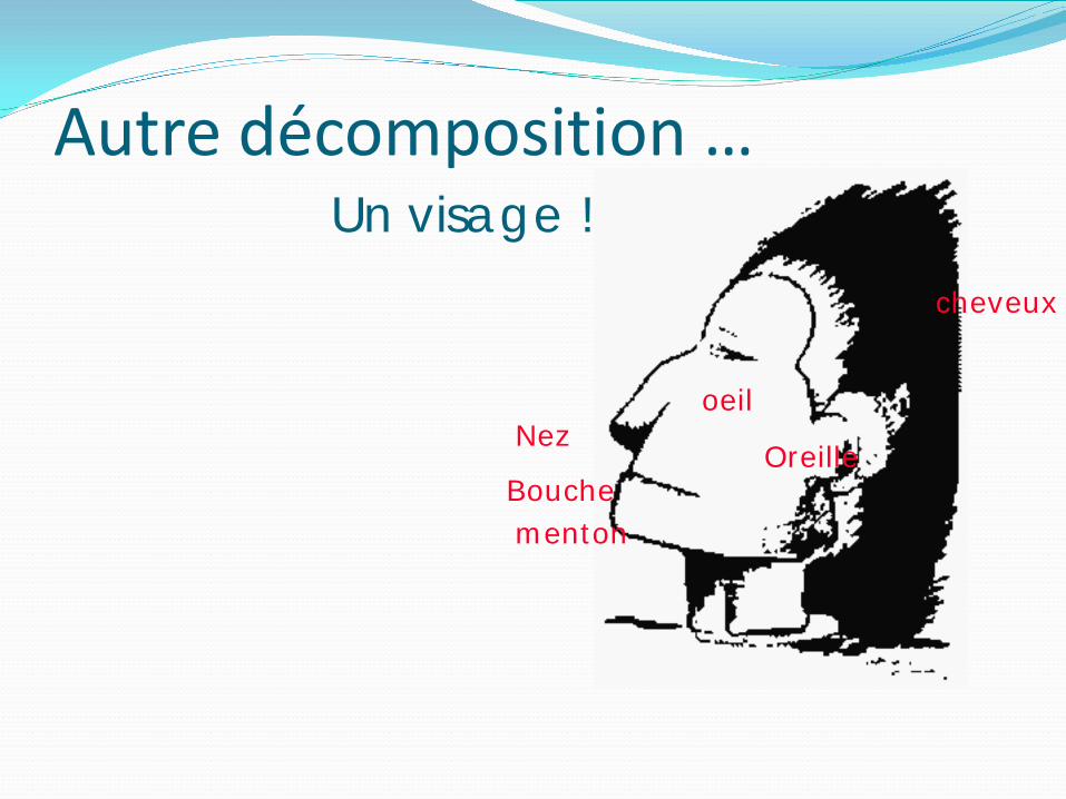
Autre décomposition …
Nez oeil
Oreille
menton Bouche
cheveux
Un visage !
Nez Oeil
Oreille
menton Bouche
Cheveux
coude cou
Gant
manteau Pocket
Cave
Un visage ! Un Eskimo!
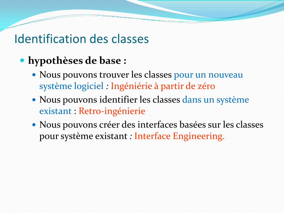
Identification des classes hypothèses de base :
Nous pouvons trouver les classes pour un nouveau système logiciel : Ingéniérie à partir de zéro
Nous pouvons identifier les classes dans un système existant : Retro-ingénierie
Nous pouvons créer des interfaces basées sur les classes pour système existant : Interface Engineering.
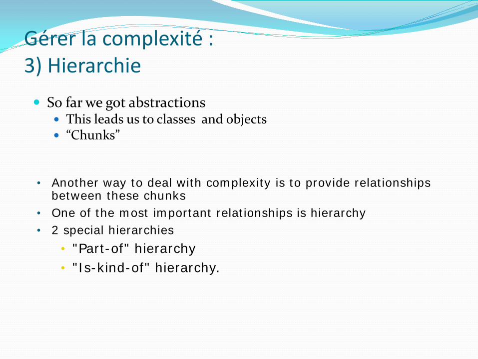
Gérer la complexité : 3) Hierarchie So far we got abstractions
This leads us to classes and objects “Chunks”
• Another way to deal with complexity is to provide relationships between these chunks
• One of the most important relationships is hierarchy • 2 special hierarchies
• "Part-of" hierarchy • "Is-kind-of" hierarchy.
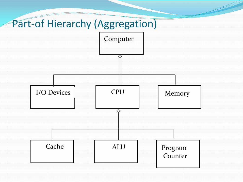
I/O Devices CPU Memory
Part-of Hierarchy (Aggregation) Computer
Cache ALU Program Counter
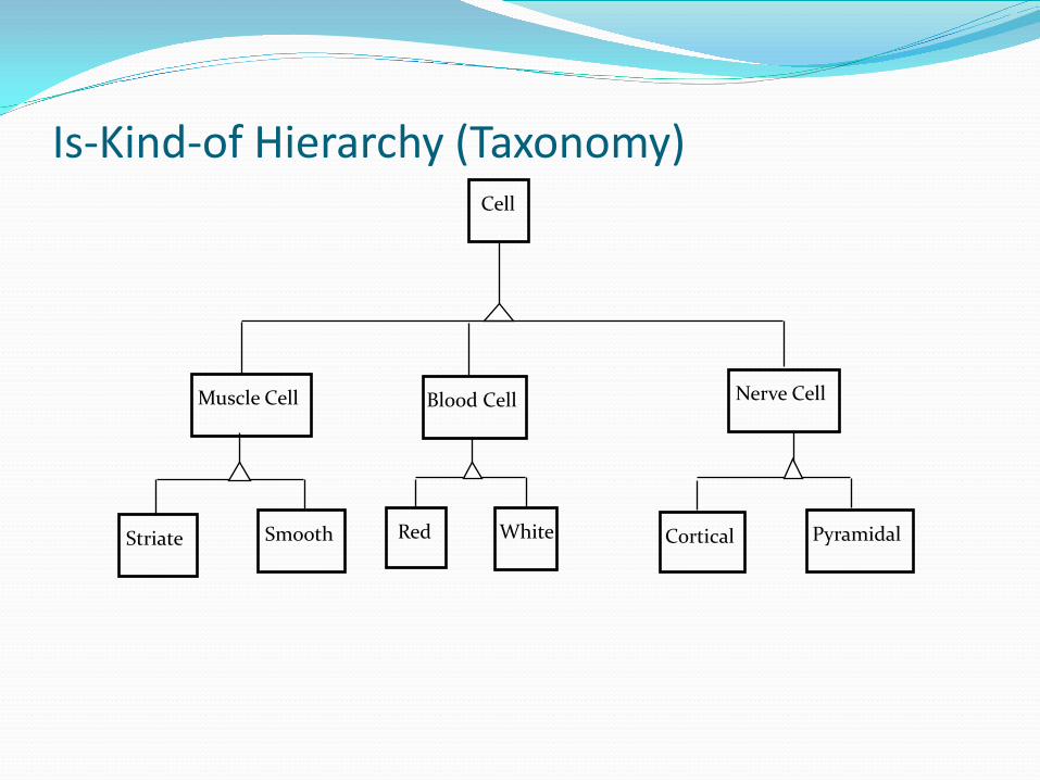
Is-Kind-of Hierarchy (Taxonomy) Cell
Muscle Cell Blood Cell Nerve Cell
Striate Smooth Red White Cortical Pyramidal
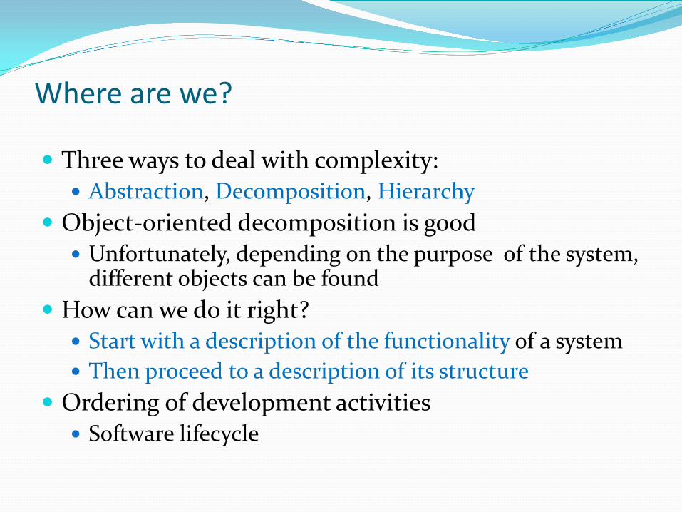
Where are we?
Three ways to deal with complexity: Abstraction, Decomposition, Hierarchy
Object-oriented decomposition is good Unfortunately, depending on the purpose of the system,
different objects can be found How can we do it right?
Start with a description of the functionality of a system Then proceed to a description of its structure
Ordering of development activities Software lifecycle
Concepts et phénomènes Classes Instances Système, sous-système Vues
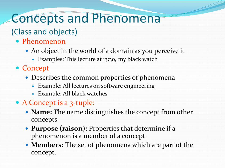
Concepts and Phenomena (Class and objects) Phenomenon
An object in the world of a domain as you perceive it Examples: This lecture at 13:30, my black watch
Concept Describes the common properties of phenomena
Example: All lectures on software engineering Example: All black watches
A Concept is a 3-tuple: Name: The name distinguishes the concept from other
concepts Purpose (raison): Properties that determine if a
phenomenon is a member of a concept Members: The set of phenomena which are part of the
concept.
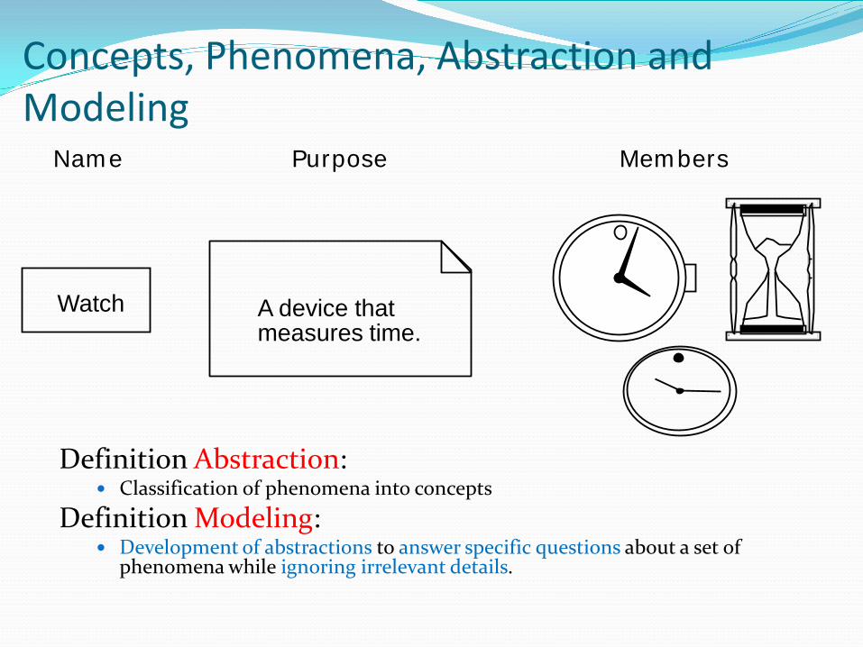
Definition Abstraction: Classification of phenomena into concepts
Definition Modeling: Development of abstractions to answer specific questions about a set of
phenomena while ignoring irrelevant details.
Members Name
Watch
Purpose
A device that measures time.
Concepts, Phenomena, Abstraction and Modeling
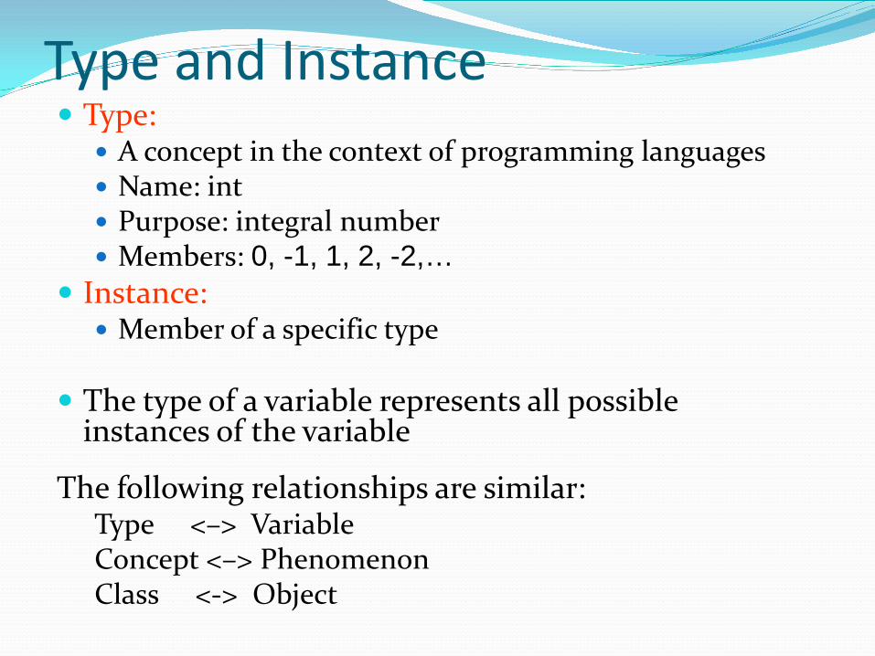
Type and Instance Type:
A concept in the context of programming languages Name: int Purpose: integral number Members: 0, -1, 1, 2, -2,…
Instance: Member of a specific type
The type of a variable represents all possible
instances of the variable
The following relationships are similar: Type <–> Variable Concept <–> Phenomenon Class <-> Object
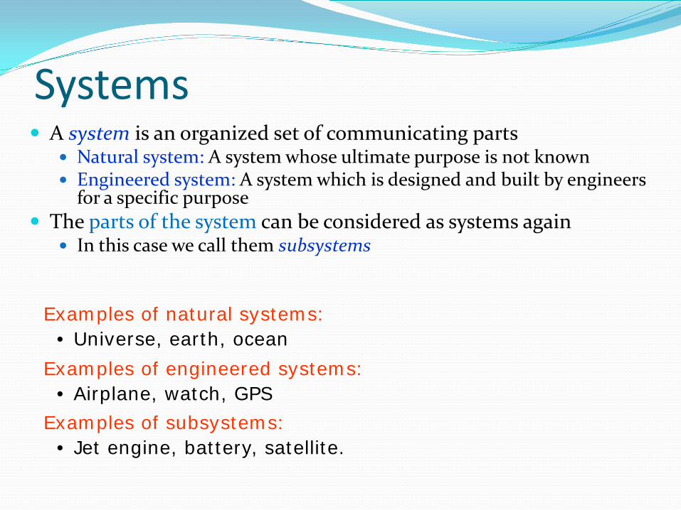
Systems A system is an organized set of communicating parts
Natural system: A system whose ultimate purpose is not known Engineered system: A system which is designed and built by engineers
for a specific purpose The parts of the system can be considered as systems again
In this case we call them subsystems
Examples of engineered systems: • Airplane, watch, GPS Examples of subsystems: • Jet engine, battery, satellite.
Examples of natural systems: • Universe, earth, ocean
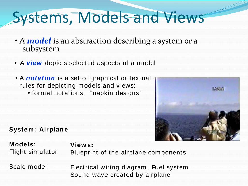
Systems, Models and Views • A model is an abstraction describing a system or a
subsystem
System: Airplane Models: Flight simulator Scale model
Views: Blueprint of the airplane components Electrical wiring diagram, Fuel system Sound wave created by airplane
• A view depicts selected aspects of a model
• A notation is a set of graphical or textual rules for depicting models and views:
• formal notations, “napkin designs”
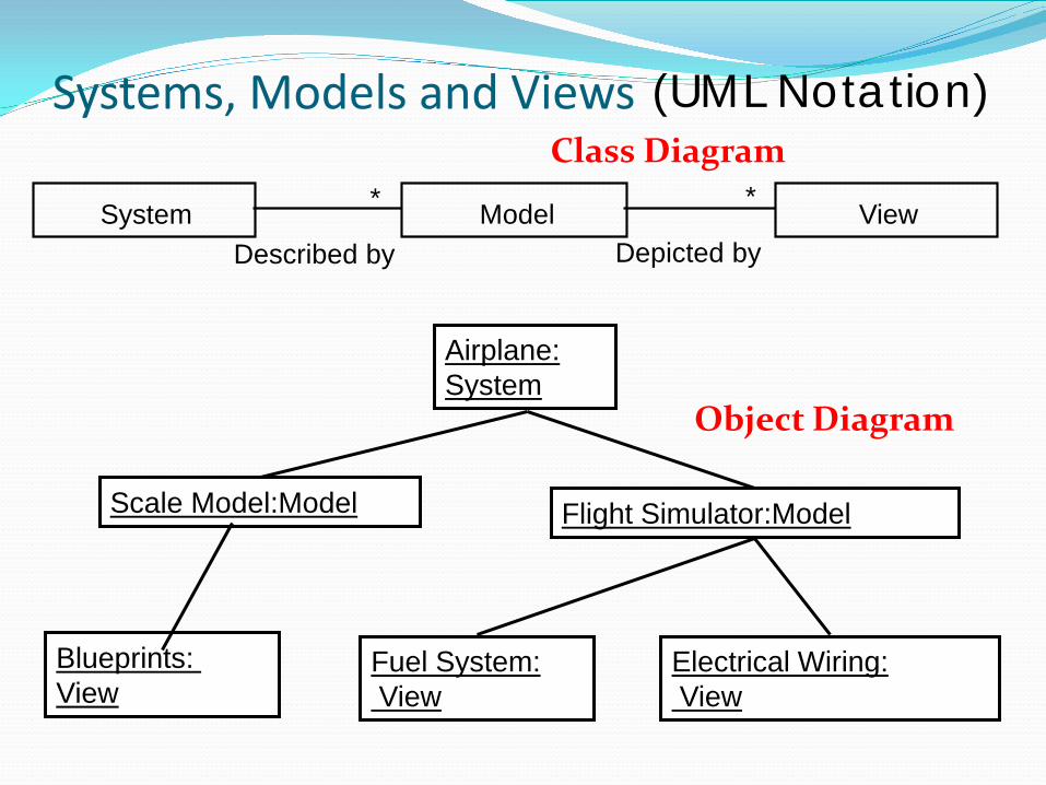
Systems, Models and Views
System View * Model *
Depicted by Described by
Airplane: System
Scale Model:Model Flight Simulator:Model
Fuel System: View
Electrical Wiring: View
Blueprints: View
(UML Notation) Class Diagram
Object Diagram
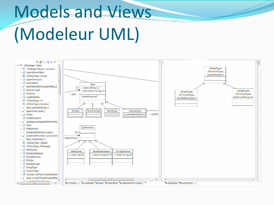
Models and Views (Modeleur UML)
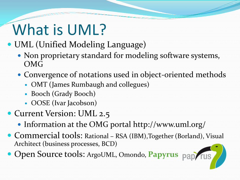
What is UML? UML (Unified Modeling Language)
Non proprietary standard for modeling software systems, OMG
Convergence of notations used in object-oriented methods OMT (James Rumbaugh and collegues) Booch (Grady Booch) OOSE (Ivar Jacobson)
Current Version: UML 2.5 Information at the OMG portal http://www.uml.org/
Commercial tools: Rational – RSA (IBM),Together (Borland), Visual Architect (business processes, BCD)
Open Source tools: ArgoUML, Omondo, Papyrus
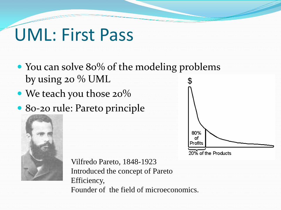
UML: First Pass You can solve 80% of the modeling problems
by using 20 % UML We teach you those 20% 80-20 rule: Pareto principle
Vilfredo Pareto, 1848-1923 Introduced the concept of Pareto Efficiency, Founder of the field of microeconomics.
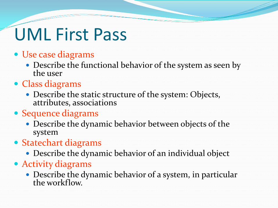
UML First Pass Use case diagrams
Describe the functional behavior of the system as seen by the user
Class diagrams Describe the static structure of the system: Objects,
attributes, associations Sequence diagrams
Describe the dynamic behavior between objects of the system
Statechart diagrams Describe the dynamic behavior of an individual object
Activity diagrams Describe the dynamic behavior of a system, in particular
the workflow.
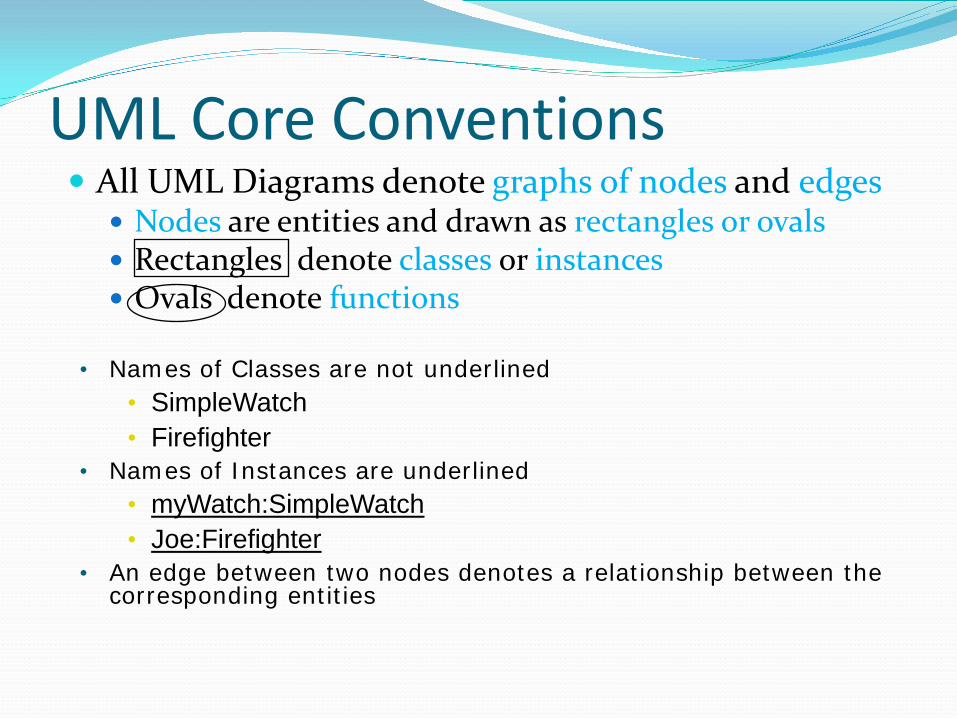
UML Core Conventions All UML Diagrams denote graphs of nodes and edges
Nodes are entities and drawn as rectangles or ovals Rectangles denote classes or instances Ovals denote functions
• Names of Classes are not underlined • SimpleWatch • Firefighter
• Names of Instances are underlined • myWatch:SimpleWatch • Joe:Firefighter
• An edge between two nodes denotes a relationship between the corresponding entities
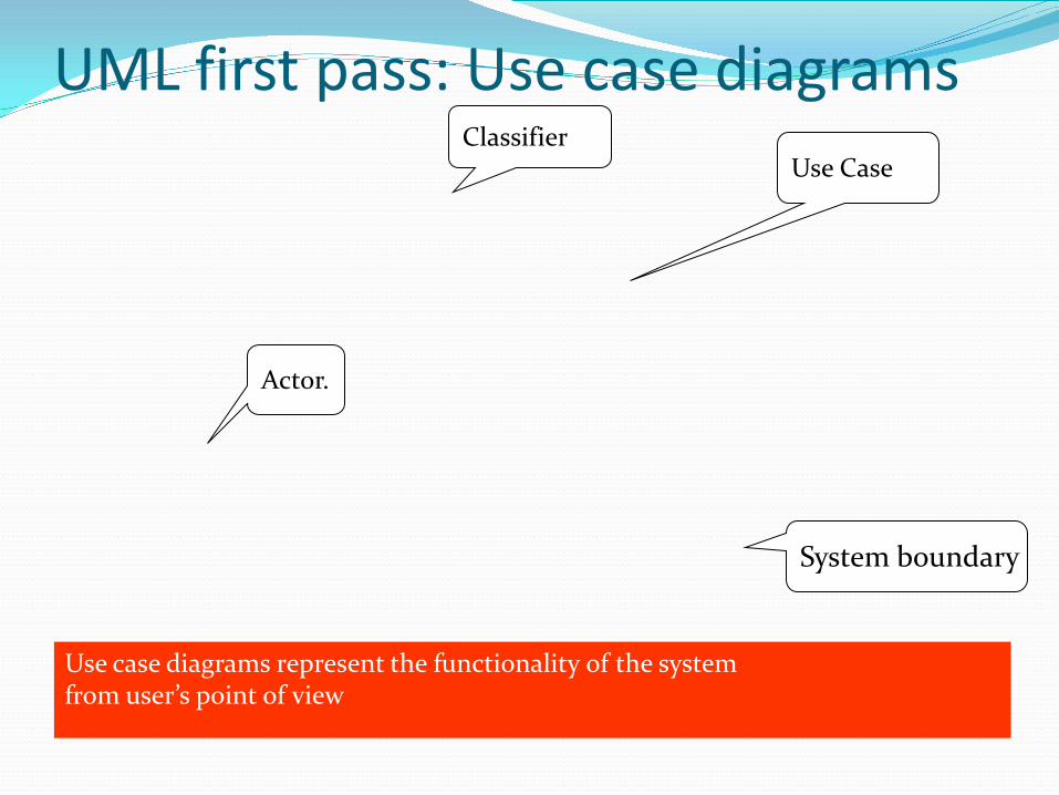
UML first pass: Use case diagrams
Use case diagrams represent the functionality of the system from user’s point of view
Actor.
Use Case
System boundary
Classifier
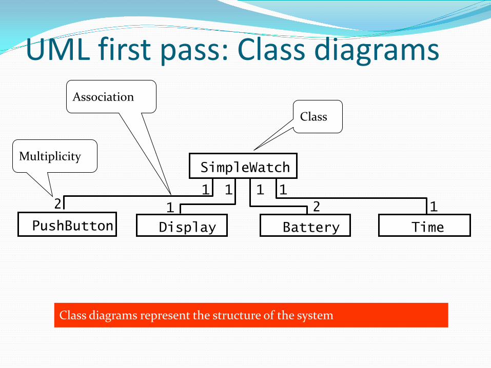
UML first pass: Class diagrams
Class
Association
Multiplicity
Class diagrams represent the structure of the system
2 1 1
1 1
1 1
2
SimpleWatch
Display Battery Time PushButton
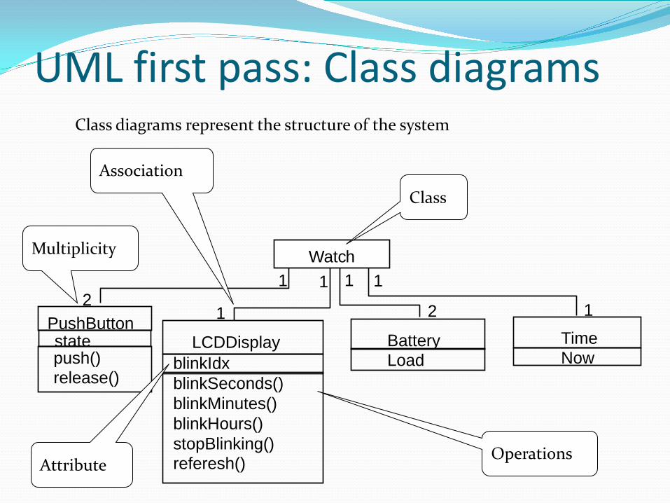
UML first pass: Class diagrams
1 2
push() release()
1
1
blinkIdx blinkSeconds() blinkMinutes() blinkHours() stopBlinking() referesh()
LCDDisplay Battery Load
1
2
1
Time Now
1
Watch
Operations
state PushButton
Attribute
Class diagrams represent the structure of the system
Class
Association
Multiplicity
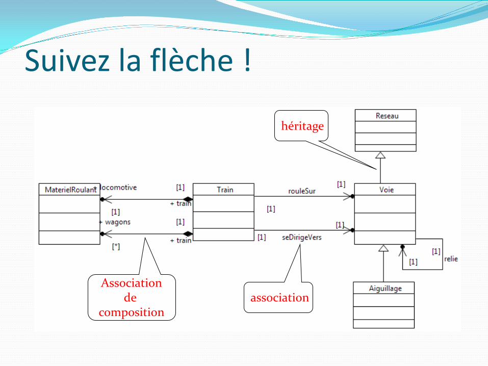
Suivez la flèche ! héritage
association Association
de composition
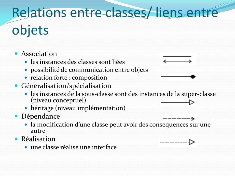
Relations entre classes/ liens entre objets Association
les instances des classes sont liées possibilité de communication entre objets relation forte : composition
Généralisation/spécialisation les instances de la sous-classe sont des instances de la super-classe
(niveau conceptuel) héritage (niveau implémentation)
Dépendance la modification d’une classe peut avoir des conséquences sur une
autre Réalisation
une classe réalise une interface
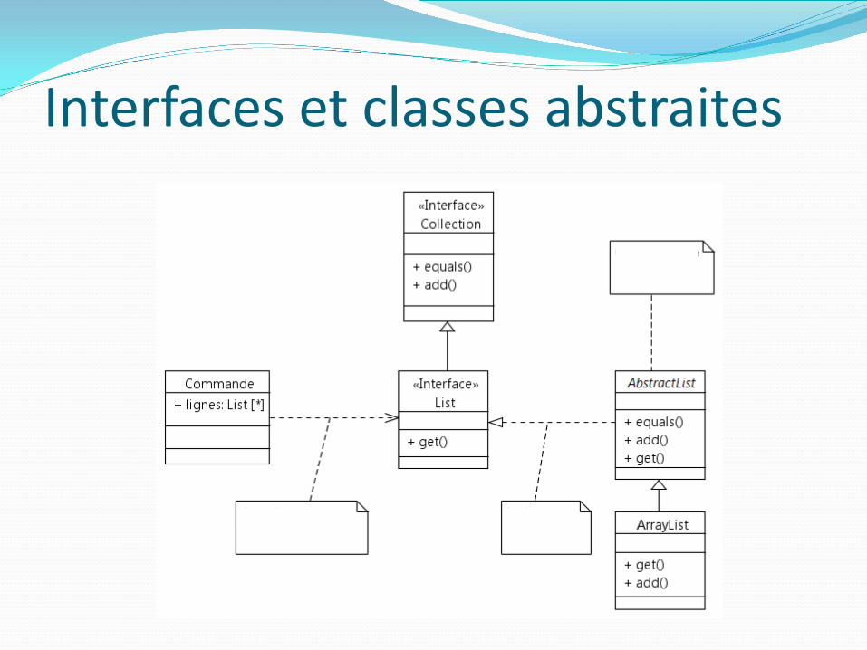
Interfaces et classes abstraites
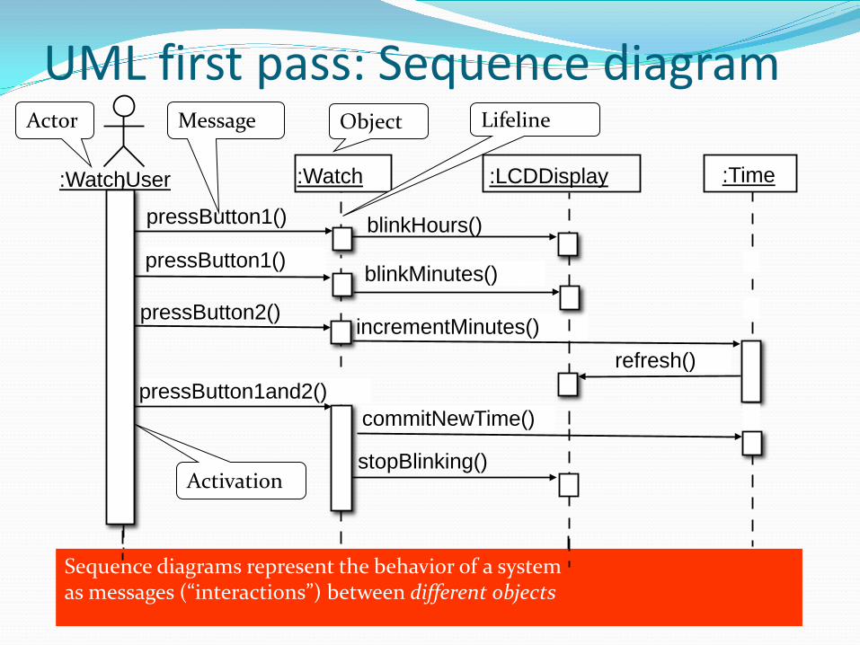
Message
UML first pass: Sequence diagram
:Time :Watch :WatchUser
Object
Activation
Sequence diagrams represent the behavior of a system as messages (“interactions”) between different objects
Actor
pressButton1()
Lifeline
blinkHours()
pressButton2() incrementMinutes()
:LCDDisplay
pressButton1and2() commitNewTime()
stopBlinking()
refresh()
pressButton1() blinkMinutes()
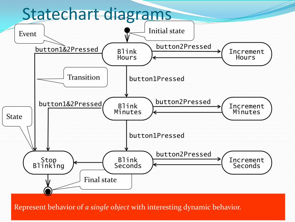
Statechart diagrams
State
Initial state
Final state
Transition
Event
Represent behavior of a single object with interesting dynamic behavior.
button1&2Pressed
button1Pressed
button2Pressed
button2Pressed
button2Pressed
button1Pressed
button1&2Pressed Increment Minutes
Increment Hours
Blink Hours
Blink Seconds
Blink Minutes
Increment Seconds
Stop Blinking
Other UML Notations UML provides many other notations, for example Deployment diagrams for modeling configurations
Useful for testing and for release management We introduce these and other notations as we go along
in the lectures OCL: A language for constraining UML models.
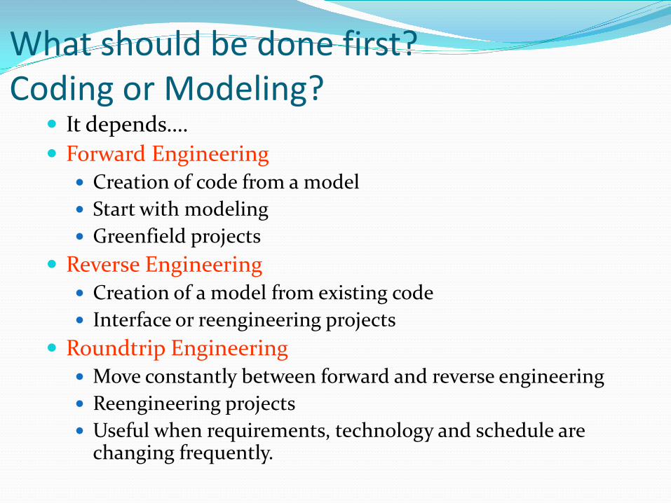
What should be done first? Coding or Modeling?
It depends…. Forward Engineering
Creation of code from a model Start with modeling Greenfield projects
Reverse Engineering Creation of a model from existing code Interface or reengineering projects
Roundtrip Engineering Move constantly between forward and reverse engineering Reengineering projects Useful when requirements, technology and schedule are
changing frequently.
UML Basic Notation Summary UML provides a wide variety of notations for modeling
many aspects of software systems Today we concentrated on a few notations:
Functional model: Use case diagram Object model: Class diagram Dynamic model: Sequence diagrams, statechart.
Que faire ensuite ? Lire les lectures obligatoire et conseillée
Obligatoire : Bruegge&Dutoit, Object-Oriented Software Engineering Chap 4 - 4.1, 4.2, 4.3
Conseillée : Chapter 1 Bruegge&Dutoit Chap 4 - 4.6
Visiter le portail de GL
Recommended